Contents
- 1. User Manual Part One
- 2. User Manual Part Two
User Manual Part Two
Configuring the FortiGate unit NAT/Route mode installation
FortiGate-50A/50B, FortiWiFi-50B and FortiGate-100 FortiOS 3.0 MR4 Install Guide
01-30004-0265-20070522 41
config system dns
set primary <address_ip>
set secondary <address_ip>
end
Example
config system dns
set primary 293.44.75.21
set secondary 293.44.75.22
end
Adding a default route
Add a default route to configure where the FortiGate unit sends traffic that should
be sent to an external network (usually the Internet). Adding the default route also
defines which interface is connected to an external network. The default route is
not required if the interface connected to the external network is configured using
DHCP or PPPoE.
To add a default route
Set the default route to the Default Gateway IP address. Enter:
config router static
edit <seq_num>
set dst <class_ip&net_netmask>
set gateway <gateway_IP>
set device <interface>
end
Verify the connection
To verify the connection, try the following:
• ping the FortiGate unit
• browse to the web-based manager GUI
• retrieve or send email from your email account
If you cannot browse to the web site or retrieve/send email from your account,
review the previous steps to ensure all information was entered correctly and try
again.
You are now finished the initial configuration of the FortiGate unit.
Example
If the default gateway IP is 10.10.1.2 and this gateway is connected to the
external interface:
config router static
edit 1
set dst 0.0.0.0 0.0.0.0
set gateway 10.10.1.2
set device external
end
100
50B
WiFi-50B

FortiGate-50A/50B, FortiWiFi-50B and FortiGate-100 FortiOS 3.0 MR4 Install Guide
42 01-30004-0265-20070522
NAT/Route mode installation Configuring the FortiGate unit
Connecting the FortiGate unit to the network(s)
When you have completed the initial configuration, you can connect the FortiGate
unit between your internal network and the Internet.
The following network connections are available on the FortiGate unit:
• Internal for connecting to your internal network
• External or WAN1 for connecting to the Internet
To connect the FortiGate unit
1Connect the Internal interface to the hub or switch connected to your internal
network.
2Connect the External or WAN1 interface to the Internet.
Connect to the public switch or router provided by your ISP. If you are a DSL or
cable subscriber, connect the External interface to the internal or LAN connection
of your DSL or cable modem.
3Optionally connect the DMZ interface to your DMZ network.
You can use a DMZ network to provide access from the Internet to a web server or
other server without installing the servers on your internal network.
Configuring the networks
If you are running the FortiGate unit in NAT/Route mode, your networks must be
configured to route all Internet traffic to the IP address of the interface where the
networks are connected.
• For the internal network, change the default gateway address of all computers
and routers connected directly to your internal network to the IP address of the
FortiGate internal interface.
• For the DMZ network, change the default gateway address of all computers
and routers connected directly to your DMZ network to the IP address of the
FortiGate DMZ interface.
• For the external network, route all packets to the FortiGate external interface.
If you are using the FortiGate unit as the DHCP server for your internal network,
configure the computers on your internal network for DHCP.
Make sure the connected FortiGate unit is functioning properly by connecting to
the Internet from a computer on the internal network. You should be able to
connect to any Internet address.
Modem is the interface for connecting an external modem to the FortiGate-50A.
You can configure the modem interface as a redundant interface or stand alone
interface to the Internet. For details on configuring the modem interface, see
“Configuring the modem for the FortiGate-50A” on page 53.
50A
DMZ for connecting to a DMZ network. You can also connect both the external
and DMZ interfaces to different Internet connections to provide a redundant
connection to the Internet.
100

Configuring the FortiGate unit Transparent mode installation
FortiGate-50A/50B, FortiWiFi-50B and FortiGate-100 FortiOS 3.0 MR4 Install Guide
01-30004-0265-20070522 43
Transparent mode installation
This section describes how to install the FortiGate unit in NAT/Route mode. This
section includes the following topics:
•Preparing to configure Transparent mode
•Using the web-based manager
•Using the command line interface
•Connecting the FortiGate unit to your network
Preparing to configure Transparent mode
Use Table 1 4 to gather the information you need to customize Transparent mode
settings.
You can configure Transparent mode using one of the following methods:
• the web-based manager GUI
• the command line interface (CLI)
The method you choose depends on the complexity of the configuration, access
and equipment, and the type of interface you are most comfortable using.
Using the web-based manager
You can use the web-based manager to complete the initial configuration of the
FortiGate unit. You can continue to use the web-based manager for all FortiGate
unit settings.
For information about connecting to the web-based manager, see “Connecting to
the web-based manager” on page 21.
The first time you connect to the FortiGate unit, it is configured to run in
NAT/Route mode.
To switch to Transparent mode using the web-based manager
1Go to System > Status.
2Select Change beside the Operation Mode.
3Select Transparent in the Operation Mode list.
4Type the Management IP/Netmask address and the Default Gateway address you
gathered in Table 14 on page 43.
5Select Apply.
Table 14: Transparent mode settings
Administrator Password:
Management IP
IP: _____._____._____._____
Netmask: _____._____._____._____
Default Gateway: _____._____._____._____
The management IP address and netmask must be valid for the
network from which you will manage the FortiGate unit. Add a default
gateway if the FortiGate unit must connect to a router to reach the
management computer.
DNS Settings Primary DNS Server: _____._____._____._____
Secondary DNS Server: _____._____._____._____

FortiGate-50A/50B, FortiWiFi-50B and FortiGate-100 FortiOS 3.0 MR4 Install Guide
44 01-30004-0265-20070522
Transparent mode installation Configuring the FortiGate unit
You do not have to reconnect to the web-based manager at this time. Once you
select Apply, the changes are immediate, and you can go to the system
dashboard to verify the FortiGate unit has changed to Transparent mode.
To configure DNS server settings
1Go to System > Network > Options.
2Enter the IP address of the primary DNS server.
3Enter the IP address of the secondary DNS server.
4Select Apply.
Using the command line interface
As an alternative to the web-based manager, you can begin the initial
configuration of the FortiGate unit using the command line interface (CLI). To
connect to the CLI, see “Connecting to the CLI” on page 23. Use the information
you gathered in Table 14 on page 43 to complete the following procedures.
To change to Transparent mode using the CLI
1Make sure you are logged into the CLI.
2Switch to Transparent mode. Enter:
config system settings
set opmode transparent
set manageip <address_ip> <netmask>
set gateway <address_ip>
end
After a few seconds, the following prompt appears:
Changing to TP mode
3To confirm you have changed to transparent mode, enter the following:
get system status
The CLI displays the status of the FortiGate unit including the management IP
address and netmask:
opmode : transparent
manageip : <address_ip> <netmask>
You should verify the DNS server settings are correct. The DNS settings carry
over from NAT/Route mode and may not be correct for your specific Transparent
mode configuration.
To verify the DNS server settings
Enter the following commands to verify the FortiGate unit’s DNS server settings:
show system dns
The above command should give you the following DNS server setting
information:
config system dns
set primary 293.44.75.21
set secondary 293.44.75.22
set fwdirtf internal
end

Configuring the FortiGate unit Transparent mode installation
FortiGate-50A/50B, FortiWiFi-50B and FortiGate-100 FortiOS 3.0 MR4 Install Guide
01-30004-0265-20070522 45
To configure DNS server settings
Set the primary and secondary DNS server IP addresses. Enter:
config system dns
set primary <address_ip>
set secondary <address_ip>
end
Example
config system dns
set primary 293.44.75.21
set secondary 293.44.75.22
end
Reconnecting to the web-based manager
When the FortiGate unit has switched to Transparent mode, you can reconnect to
the web-based manager using the new IP address. Browse to https:// followed by
the new IP address. If you connect to the management interface through a router,
make sure you have added a default gateway for that route to the management IP
default gateway field.
Connecting the FortiGate unit to your network
When you complete the initial configuration, you can connect the FortiGate unit
between your internal network and the Internet, and optionally connect an
additional network to the other interfaces if applicable.
To connect the FortiGate unit running in Transparent mode:
1Connect the Internal interface to the hub or switch connected to your internal
network.
2Connect the External or WAN1 interface to network segment connected to the
external firewall or router.
Connect to the public switch or router provided by your ISP.
Verify the connection
To verify the connection, try the following:
• ping the FortiGate unit
• browse to the web-based manager GUI
• retrieve or send email from your email account
If you cannot browse to the web site or retrieve/send email from your account,
review the previous steps to ensure all information was entered correctly and try
again.
FortiGate-50A/50B, FortiWiFi-50B and FortiGate-100 FortiOS 3.0 MR4 Install Guide
46 01-30004-0265-20070522
Next steps Configuring the FortiGate unit
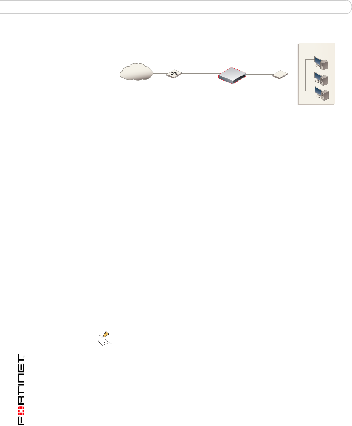
Figure 10: FortiGate-50B Transparent mode connections
Next steps
Use the following information to configure FortiGate system time, and to configure
antivirus and attack definition updates.
Refer to the FortiGate Administration Guide for complete information on
configuring, monitoring, and maintaining your FortiGate unit.
Set the date and time
For effective scheduling and logging, the FortiGate system date and time must be
accurate. You can either manually set the system date and time or configure the
FortiGate unit to automatically keep its time correct by synchronizing with a
Network Time Protocol (NTP) server.
To set the date and time
1Go to System > Status.
2Under System Information > System Time, select Change.
3Select Refresh to display the current FortiGate system date and time.
4Select your Time Zone from the list.
5Optionally, select Automatically adjust clock for daylight saving changes check
box.
6Select Set Time and set the FortiGate system date and time.
7Set the hour, minute, second, month, day, and year as required.
8Select OK.
To use NTP to set the FortiGate date and time
1Go to System > Status.
2Under System Information > System Time, select Change.
3Select Synchronize with NTP Server to configure the FortiGate unit to use NTP to
automatically set the system time and date.
4Enter the IP address or domain name of the NTP server that the FortiGate unit
can use to set its time and date.
FortiGate-50B
Internal
network
Internet
Router
(or public switch)
Hub,
switch or router
Management
Computer
Internal
WAN1
Note: If you choose the option Automatically adjust clock for daylight saving changes, the
system time must be manually adjusted after daylight savings time ends.

Configuring the FortiGate unit Next steps
FortiGate-50A/50B, FortiWiFi-50B and FortiGate-100 FortiOS 3.0 MR4 Install Guide
01-30004-0265-20070522 47
5Specify how often the FortiGate unit should synchronize its time with the NTP
server.
6Select OK.
Updating antivirus and IPS signatures
Configure the FortiGate unit to connect to the FortiGuard Distribution Network
(FDN) to update the antivirus (including grayware), antispam and IPS attack
definitions.
The FDN is a world wide network of FortiGuard Distribution Servers (FDS). When
the FortiGate unit connects to the FDN, it connects to the nearest FDS. To do this,
all FortiGate units are programmed with a list of FDS addresses sorted by nearest
time zone according to the time zone configured for the FortiGate unit.
You can update your antivirus and IPS signatures using the web-based manager
or the CLI. Before you can begin receiving updates, you must register your
FortiGate unit from the Fortinet web page.
After registering your FortiGate unit, verify the FortiGate unit can connect to the
FDN:
• Check that the FortiGate unit’s system time is correct.
• From the web-based manager, select refresh from the FortiGuard Center.
If you cannot connect to the FDN, follow the procedure for registering your
FortiGate unit and try again or see “Adding an override server” on page 49.
Updating antivirus and IPS signatures from the web-based
manager
After you have registered your FortiGate unit, you can update antivirus and IPS
signatures using the web-based manager. The FortiGuard Center enables you to
receive push updates, allow push update to a specific IP address, and schedule
updates for daily, weekly, or hourly intervals.
To update antivirus definitions and IPS signatures
1Go to System > Maintenance > FortiGuard Center.
2Select the blue arrow for AntiVirus and IPS Downloads to expand the options.
3Select Update Now to update the antivirus definitions.
If the connection to the FDN is successful, the web-based manager displays a
message similar to the following:
Your update request has been sent. Your database will
be updated in a few minutes. Please check your update
page for the status of the update.
After a few minutes, if an update is available, the System FortiGuard Center page
lists new version information for antivirus definitions. The System Status page
also displays new dates and version numbers for the antivirus definitions.
Messages are recorded to the event log indicating whether the update was
successful or not.
Note: Update AV and IPS signatures on a regular basis. If you do not update AV and IPS
signatures regularly, the FortiGate unit can become vulnerable to new viruses.

FortiGate-50A/50B, FortiWiFi-50B and FortiGate-100 FortiOS 3.0 MR4 Install Guide
48 01-30004-0265-20070522
Next steps Configuring the FortiGate unit
Updating the IPS signatures from the CLI
You can update IPS signatures using the CLI. Use the following procedure to
update IPS signatures.
To update IPS signatures using the CLI
1Log into the CLI.
2Enter the following CLI command:
configure system autoupdate ips
set accept-recommended-settings enable
end
Scheduling antivirus and IPS updates
You can schedule regular, automatic updates of antivirus and IPS signatures,
either from the web-based manager or the CLI.
To enable schedule updates from the web-based manager
1Go to System > Maintenance > FortiGuard Center.
2Select the Scheduled Update check box.
3Select one of the following to check for and download updates
4Select Apply.
The FortiGate unit starts the next scheduled update according to the new update
schedule.
Whenever the FortiGate unit runs a scheduled update, the event is recorded in the
FortiGate event log.
To enable schedule updates from the CLI
1Log into the CLI.
2Enter the following command:
config system autoupdate schedule
set frequency {every | daily | weekly}
set status {enable | disable}
set time <hh:mm>
end
Note: Updating antivirus definitions can cause a very short disruption in traffic currently
being scanned while the FortiGate unit applies the new signature database. Schedule
updates when traffic is light, for example overnight, to minimize any disruption.
Note: You can only update antivirus definitions from the web-based manager.
Every Once every 1 to 23 hours. Select the number of hours and
minutes between each update request.
Daily Once a day. You can specify the time of day to check for updates.
Weekly Once a week. You can specify the day of the week and time of day
to check for updates.

Configuring the FortiGate unit Next steps
FortiGate-50A/50B, FortiWiFi-50B and FortiGate-100 FortiOS 3.0 MR4 Install Guide
01-30004-0265-20070522 49
Example
config system autoupdate schedule
set update every Sunday
set frequency weekly
set status enable
set time 16:45
end
Adding an override server
If you cannot connect to the FDN, or if your organization provides updates using
their own FortiGuard server, use the following procedures to add the IP address of
an override FortiGuard server in either the web-based manager or the CLI.
To add an override server from the web-based manager
1Go to System > Maintenance > FortiGuard Center.
2Select the blue arrow for AntiVirus and IPS Downloads to expand the options.
3Select the Use override server address check box.
4Type the fully qualified domain name or IP address of a FortiGuard server.
5Select Apply.
The FortiGate unit tests the connection to the override server.
If the FDN setting changes to available, the FortiGate unit has successfully
connected to the override server.
If the FDN stays set to not available, the FortiGate unit cannot connect to the
override server. Check the FortiGate configuration and network configuration for
settings that would prevent the FortiGate unit from connecting to the override
FortiGuard server.
To add an override server using the CLI
1Log into the CLI.
2Enter the following command:
config system autoupdate override
set address
set status
end

FortiGate-50A/50B, FortiWiFi-50B and FortiGate-100 FortiOS 3.0 MR4 Install Guide
50 01-30004-0265-20070522
Next steps Configuring the FortiGate unit

Configuring the modem interface Connecting a modem to the FortiGate-50A
FortiGate-50A/50B, FortiWiFi-50B and FortiGate-100 FortiOS 3.0 MR4 Install Guide
01-30004-0265-20070522 51
Configuring the modem interface
The following sections will cover how to configure the FortiGate-50A modem
using the CLI.
The FortiGate-50A supports a redundant or stand alone 56K modem interface in
NAT/Route mode.
• In redundant mode, the modem interface automatically takes over from a
selected Ethernet interface when that Ethernet interface is unavailable.
• In stand alone mode, the modem interface is the connection from the FortiGate
unit to the Internet.
When connecting to an ISP in either configuration, the modem can automatically
dial up to three dial-up accounts until the modem connects to an ISP.
This section includes the following topics:
•Connecting a modem to the FortiGate-50A
•Selecting a modem mode
•Configuring the modem for the FortiGate-50A
•Adding a Ping Server
•Adding firewall policies for modem connections
Connecting a modem to the FortiGate-50A
The FortiGate-50A can operate with most standard external serial interface
modems that support standard Hayes AT commands. To connect, install a
USB-to-serial converter between one of the two USB ports on the FortiGate unit
and the serial port on the modem. The FortiGate unit does not support a direct
USB connection between the two devices.
The modem interface is only available on the FortiGate-50A.
50A
FortiGate-50A/50B, FortiWiFi-50B and FortiGate-100 FortiOS 3.0 MR4 Install Guide
52 01-30004-0265-20070522
Selecting a modem mode Configuring the modem interface
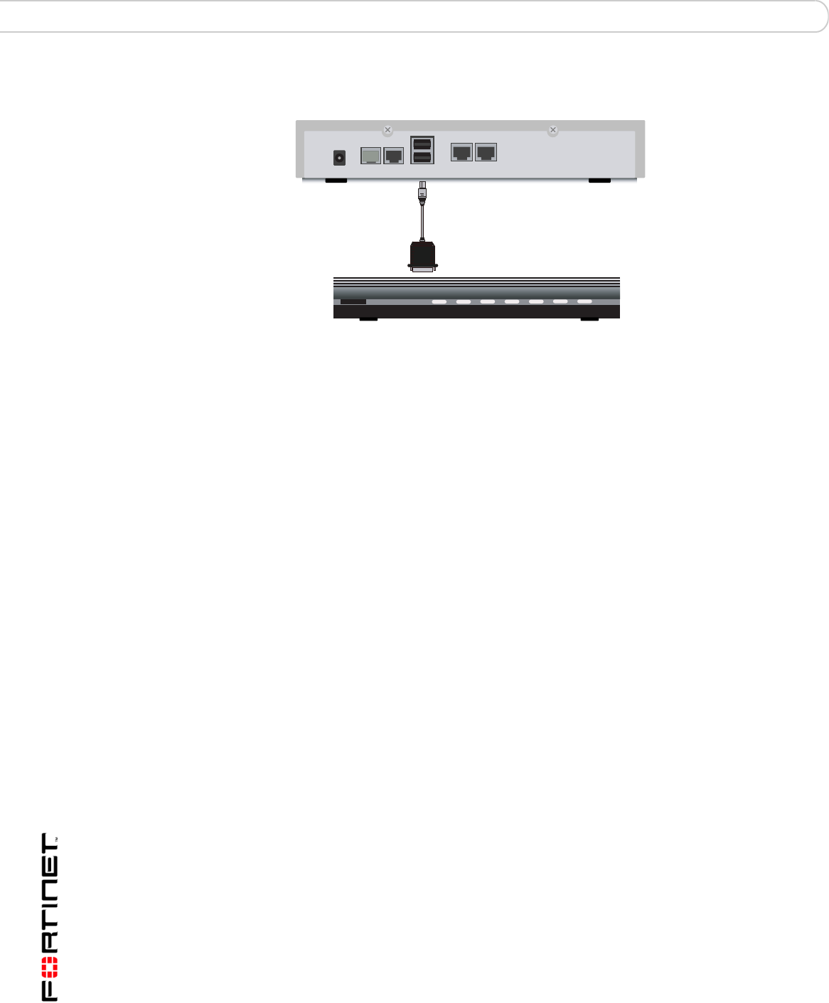
Figure 11: Example modem interface network connection
Selecting a modem mode
The modem interface can work in one of two modes:
• redundant mode
• stand alone mode
Redundant mode configuration
The redundant modem interface serves as a backup to the Ethernet interface. If
that Ethernet interface disconnects from its network, the modem automatically
dials the configured dial-up account(s). When the modem connects to a dial-up
account, the FortiGate unit routes IP packets normally destined for the selected
Ethernet interface to the modem interface. During this time, the unit pings the
Ethernet connection to check when it is back online.
When the Ethernet interface can connect to its network again, the FortiGate unit
disconnects the modem interface and switches back to the Ethernet interface.
For the FortiGate unit to switch from an Ethernet interface to the modem you must
select the name of the interface in the modem configuration and configure a ping
server for that interface. You must also configure firewall policies for connections
between the modem interface and other FortiGate interfaces.
Stand alone mode configuration
In stand alone mode, you manually connect the modem to a dial-up account. The
modem interface operates as the primary connection to the Internet. The
FortiGate unit routes traffic through the modem interface, which remains
permanently connected to the dial-up account.
If the connection to the dial-up account fails, the FortiGate unit modem
automatically redials the number. The modem redials the ISP number based on
the amount of times specified by the redial limit, or until it connects to a dial-up
account.
Internal
External
DC+12V
USB
Modem Console
V.9 2
External modem
USB-to-serial converter
FortiGate-50A

Configuring the modem interface Configuring the modem for the FortiGate-50A
FortiGate-50A/50B, FortiWiFi-50B and FortiGate-100 FortiOS 3.0 MR4 Install Guide
01-30004-0265-20070522 53
In stand alone mode the modem interface replaces the external Ethernet
interface. You must also configure firewall policies for connections between the
modem interface and other FortiGate interfaces.
Configuring the modem for the FortiGate-50A
Configure the modem for the FortiGate-50A using the CLI. The following table of
CLI commands are specifically for the FortiGate-50A modem configuration.
Table 15: CLI commands for the FortiGate-50A
Keywords and
variables
Description Default
altmode
{enable | disable}
Enable for installations using PPP in China. enable
auto-dial
{enable | disable}
Enable to dial the modem automatically if the
connection is lost, or the FortiGate unit is
restarted.
dial-on-demand must be disabled.
mode must be standalone.
disable
connect_timeout
<seconds>
Set the connection completion timeout (30-255
seconds). 90
dial-on-demand
{enable | disable}
Enable the FortiGate unit to dial the modem
when packets are routed to the modem
interface. The modem disconnects after it
reaches the idle-timer period value if there
is no traffic through the modem interface within
that time. When traffic occurs on the interface,
the FortiGate unit dials the modem again.
auto-dial must be disabled when in
standalone mode.
disable
holddown-timer
<seconds>
Used only when the modem is configured as a
backup for an interface. Set the time (1-50B
seconds) that the FortiGate unit waits before
switching from the modem interface to the
primary interface, after the primary interface
has been restored.
mode must be redundant.
60
idle-timer
<minutes>
Set the number of minutes the traffic through
the modem connection is idle before it the
FortiGate unit disconnects.
mode must be standalone.
5
interface <name> Enter an interface name to associate the
modem interface with the Ethernet interface
that you want to either back up (backup
configuration) or replace (standalone
configuration).
No default.
mode <mode> Enter the required mode:
• standalone
The modem interface is the connection from
the FortiGate unit to the Internet.
• redundant
The modem interface automatically takes over
from a selected Ethernet interface when that
Ethernet interface is unavailable.
standalone
passwd1
<password_srt>
Enter the password used to access the
specified dialup account.
No default

FortiGate-50A/50B, FortiWiFi-50B and FortiGate-100 FortiOS 3.0 MR4 Install Guide
54 01-30004-0265-20070522
Configuring the modem for the FortiGate-50A Configuring the modem interface
Table 15: CLI commands for the FortiGate-50A
passwd2
<password_str>
Enter the password used to access the
specified dialup account.
No default.
passwd3
<password_str>
Enter the password used to access the
specified dial-up account.
No default.
peer_modem1
{actiontec |
ascendTNT |
generic}
If the modem at phone1 is Actiontec or
AscendTNT, select that type, otherwise leave
setting as generic. This setting applies to
models 50AM, 60M, and WiFi-50BM only.
generic
peer_modem2
{actiontec |
ascendTNT |
generic}
If the modem at phone2 is Actiontec or
AscendTNT, select that type, otherwise leave
setting as generic. This setting applies to
models 50AM, 60M, and WiFi-50BM only.
generic
peer_modem2
{actiontec |
ascendTNT |
generic}
If the modem at phone3 is Actiontec or
AscendTNT, select that type, otherwise leave
setting as generic. This setting applies to
models 50AM, 60M, and WiFi-50BM only.
generic
phone1
<phone-number>
Enter the phone number required to connect to
the dial-up account. Do not add spaces to the
phone number. Make sure to include standard
special characters for pauses, country codes,
and other functions as required by your modem
to connect to your dial-up account.
No default.
phone2
<phone-number>
Enter the phone number required to connect to
the dialup account. Do not add spaces to the
phone number. Make sure to include standard
special characters for pauses, country codes,
and other functions as required by your modem
to connect to your dialup account.
No default.
phone3
<phone-number>
Enter the phone number required to connect to
the dialup account. Do not add spaces to the
phone number. Make sure to include standard
special characters for pauses, country codes,
and other functions as required by your modem
to connect to your dialup account.
No default.
redial
<tries_interger>
Set the maximum number of times (1-10) the
FortiGate unit dials the ISP to restore an active
connection on the modem interface. Select
none to allow the modem to redial without a
limit.
No default.
status {disable |
enable}
Enable or disable modem support. disable
username1
<name_str>
Enter the user name used to access the
specified dial-up account.
No default.
username2
<name_str>
Enter the user name used to access the
specified dialup account.
No default.
username3
<name_str>
Enter the user name used to access the
specified dialup account.
No default.

Configuring the modem interface Adding a Ping Server
FortiGate-50A/50B, FortiWiFi-50B and FortiGate-100 FortiOS 3.0 MR4 Install Guide
01-30004-0265-20070522 55
Example
config system modem
set action dial
set status enable
set holddown-time 5
set interface wan1
set passwd1 acct1passwd
set phone1 1234567891
set redial 10
set username1 acct1user
end
Adding a Ping Server
Adding a ping server is required for routing failover for the modem in redundant
mode. A ping server confirms the connectivity to an Ethernet interface. If the
Ethernet interface fails, the ping server continually checks to see when the
connection has been restored.
To add a ping server to an interface
1Go to System > Network > Interface.
2Choose an interface and select Edit.
3Set Ping Server to the IP address of the next hop router on the network connected
to the interface.
4Select the Enable check box.
5Select OK to save the changes.
Dead gateway detection
The FortiGate unit uses dead gateway detection to ping the Ping Server IP
address to make sure the FortiGate unit can connect to this IP address.
Modify dead gateway detection to control how the FortiGate unit confirms
connectivity with a ping server added to an interface configuration. For information
about adding a ping server to an interface, above.
To modify the dead gateway detection settings
1Go to System > Network > Options.
2For Detection Interval, type a number in seconds to specify how often the
FortiGate unit tests the connection to the ping target.
3For Fail-over Detection, type a number of times that the connection test fails
before the FortiGate unit assumes the gateway is no longer functioning.
4Select Apply.

FortiGate-50A/50B, FortiWiFi-50B and FortiGate-100 FortiOS 3.0 MR4 Install Guide
56 01-30004-0265-20070522
Adding firewall policies for modem connections Configuring the modem interface
Adding firewall policies for modem connections
The modem interface requires firewall addresses and policies. You can add one
or more addresses to the modem interface. For information about adding
addresses, see the FortiGate Administration Guide. When you add addresses, the
modem interface appears on the policy grid.
You can configure firewall policies to control the flow of packets between the
modem interface and the other interfaces on the FortiGate unit. For information
about adding firewall policies, see the FortiGate Administration Guide.

Using a wireless network Setting up a wireless network
FortiGate-50A/50B, FortiWiFi-50B and FortiGate-100 FortiOS 3.0 MR4 Install Guide
01-30004-0265-20070522 57
Using a wireless network
In a wired network, computers are connected through a series of cables that
transfer information. In a wireless network, information is transferred over radio
waves. There are factors which affect the transmission of data “on the air” that you
must take into account when setting up a wireless network.
This section outlines the considerations for wireless networking and steps you can
take to make your wireless network as efficient as possible.
This section includes the following topics:
•Setting up a wireless network
•Wireless Security
•FortiWiFi-50B operation modes
•Setting up the FortiWiFi-50B as an Access Point
Setting up a wireless network
In its simplest form, a wireless network is an Access Point communicating with
one wireless device. An Access Point (AP) is a device that provides a
communications hub for a wireless network. The AP and the wireless devices
operate on a common radio channel. The FortiWiFi-50B acts as an AP and
assigns all wireless users to the same subnet. With the proper firewall policies
and routing, wireless users can communicate with users on the internal network or
on an external network such as the Internet.
This chapter is specifically for the FortiWiFi-50B.
WiFi-50B
FortiGate-50A/50B, FortiWiFi-50B and FortiGate-100 FortiOS 3.0 MR4 Install Guide
58 01-30004-0265-20070522
Setting up a wireless network Using a wireless network
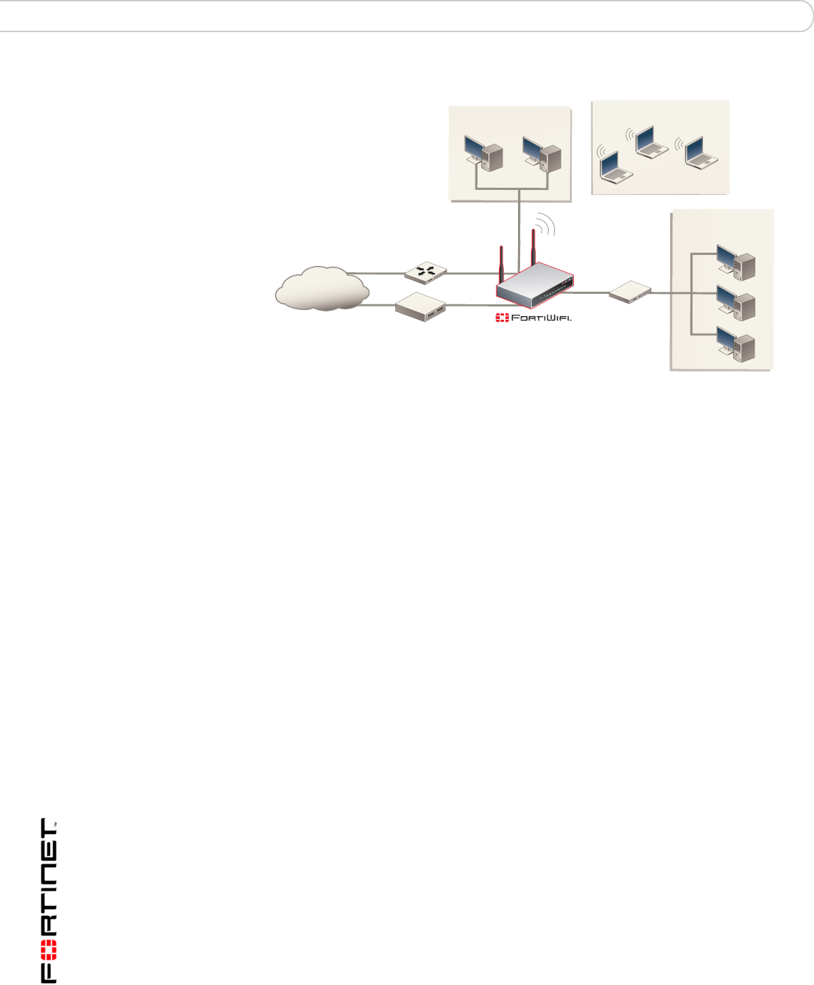
Figure 12: FortiWiFi-50B as an Access Point
Positioning an Access Point
When placing the FortiWiFi-50B AP, your main concern is providing a strong
signal to all users. A strong signal ensures a fast connection and the efficient
transfer of data. A weaker signal means a greater chance of data transmission
errors and the need to re-send information, slowing down data transfer.
Consider the following guidelines when placing the FortiWiFi-50B AP:
• Physical barriers can impede the radio signals. Solid objects such as walls,
furniture and people absorb radio waves, weakening the signal. Be aware of
the physical barriers in your office space that may reduce a signal. If there is
enough physical interference, you may encounter dead spots that receive no
signals.
• Ensure the FortiWiFi-50B AP is located in a prominent location within a room
for maximum coverage, rather than in a corner.
• Construction materials used in a building can also weaken radio signals.
Rooms with walls of concrete or metal can affect the signal strength.
Radio Frequency interface
The 802.11 standard uses a frequency range of 2.4 to 2.483 GHz. Radio
frequency (RF) interference occurs when other devices send RF signals during
their normal operation that use the same frequency as the FortiWiFi-50B AP.
Wireless devices such as 2.4 GHz cordless phones, microwave ovens and
Bluetooth devices can interfere with packet transmissions on a wireless network.
DMZ
Network
Internal
Network
Internet
MODEM / DSL / Cable
Router
Internal
DMZ
WAN2
WAN1
Wireless Network
Using a wireless network Setting up a wireless network
FortiGate-50A/50B, FortiWiFi-50B and FortiGate-100 FortiOS 3.0 MR4 Install Guide
01-30004-0265-20070522 59
To avoid RF interference:
• Remove these devices from the immediate area where users are working.
Something as simple as a Bluetooth enabled mouse may cause transmission
interruptions.
• Keep the FortiWiFi-50B AP and wireless devices at least 10 feet away from
appliances such as microwave ovens and cordless phones.
• If you must have a cordless phone, select one that does not use the 2.4GHz
frequency range.
• Consider more FortiWiFi-50B APs to help strengthen the signal. The weaker
the signal, the slower the transmission will be as it tries to compete against
other wireless devices.
• Set a channel that users and FortiWiFi-50B APs will specifically use can
improve signal quality.
Using multiple access points
If you cannot avoid some of these impediments due to the shape of the office or
building materials used, you may need to use multiple FortiWiFi-50B APs to help
distribute the radio signal around the room. Figure 13 shows how positioning two
FortiWiFi-50B APs within a uniquely shaped office space helps to distribute
signals around the area.
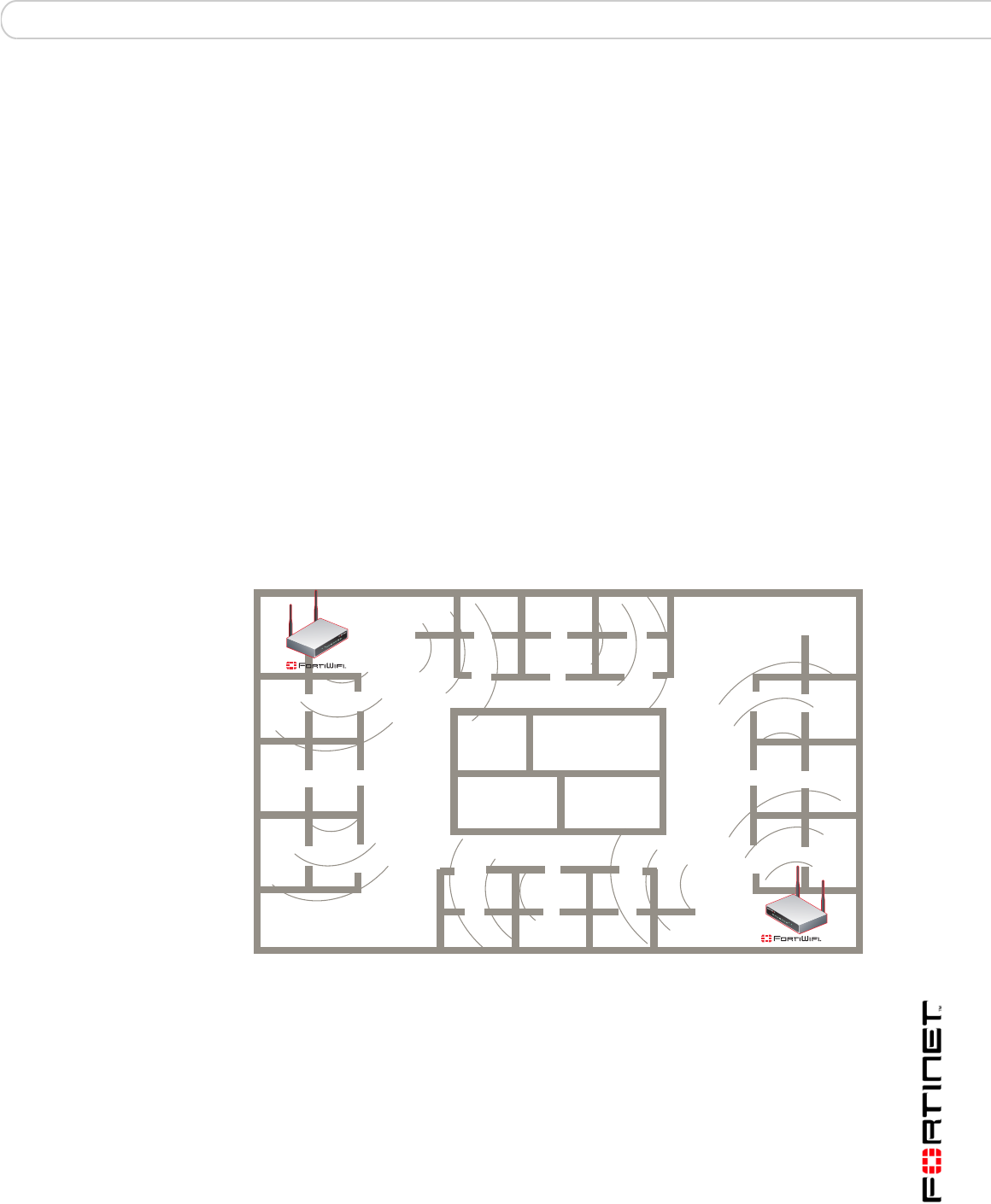
Figure 13: Using multiple APs to provide a constant strong signal.
This sample office has washrooms, a stairwell and an elevator shaft in the center
of the building, making it impossible to use a single FortiWiFi-50B AP effectively.
The elevator shaft and multiple metal stalls in the washrooms can cause signal
degradation. However, placing a FortiWiFi-50B AP in opposite corners of the
office provides maximum coverage.
When using multiple APs, each FortiWiFi-50B AP should be set to a different
channel to avoid interference in areas where signals from both FortiWiFi-50B
devices can be received.
Elevator
Washrooms
Stairs

FortiGate-50A/50B, FortiWiFi-50B and FortiGate-100 FortiOS 3.0 MR4 Install Guide
60 01-30004-0265-20070522
Wireless Security Using a wireless network
Wireless Security
Radio waves transmitted between a wireless device and access points provide the
weakest link between the wireless device and network servers. Wireless
networking can be risky because information travels on radio waves, which is a
public medium. The 802.11 standard includes security options to stop your
information from being intercepted by unwanted sources. These are Wireless
Equivalent Privacy (WEP) and WiFi Protected Access (WPA) encryption. Wireless
encryption is only used between the wireless device and the AP. The AP decrypts
the data before sending it along the wired network. The FortiWiFi-50B supports
both encryption methods.
Wireless Equivalent Privacy (WEP)
WEP security uses an encryption key between the wireless device and the AP. For
WEP security, the wireless device and AP must use the same encryption key, and
is manually typed by the wireless user and administrator. When activated, the
wireless device encrypts the data with the encryption key for each frame using
RSA RC4 ciphers.
There has been criticism of WEP security. WEP keys are static. They must be
changed manually and frequently on both the wireless device and the APs. On a
small company or network with a few users and APs, this is not a big issue.
However, the more users and APs, changing WEP keys regularly can become an
administrative headache and potentially error prone. Consequently, keys are
rarely changed over months or years, leaving a hacker plenty of time to get the
key and gain access to the network.
In small wireless networking environments, activating WEP security will
significantly minimize outside infiltrators from getting in your network and is better
than no security at all. However, it is still very important that you regularly change
the WEP key, at least weekly; or monthly at most.
Wi-Fi Protected Access (WPA)
WPA was developed to replace the WEP standard and provide a higher level of
data protection for wireless networks. WPA provides two methods of
authentication; through 802.1X authentication or pre-shared keys.
802.1X authenticates users through an EAP authentication server such as a
RADIUS server authenticates each user before they can connect to the network.
The encryption keys can be changed at varying intervals to minimize the
opportunity for hackers to crack the key being used.
In a network setup where a RADIUS server is not a viable option, WPA also
provides authentication with preshared keys using Temporal Key Integrity Protocol
(TKIP). Using TKIP, the encryption key is continuously re-keyed while the user is
connected to the wireless network. This creates a unique key on every data
packet. To further ensure data integrity, a Message Integrity Code (MIC also
known as Michael) is incorporated into each packet. It uses an 8 byte message
integrity code that is encrypted using the MAC addresses and data from each
frame to provide a more secure packet transmission.
WPA provides a more robust security between the wireless device and the access
point. The FortiWiFi-50B device supports both WPA methods.

Using a wireless network FortiWiFi-50B operation modes
FortiGate-50A/50B, FortiWiFi-50B and FortiGate-100 FortiOS 3.0 MR4 Install Guide
01-30004-0265-20070522 61
Additional security measures
The FortiWiFi-50B includes other security measures you can use to block
unwanted users from accessing your wireless network. By setting a few extra
options, you can be assured your network and its information is secure.
MAC address filtering
To improve the security of your wireless network, consider enabling MAC address
filtering on the FortiWiFi-50B unit. By enabling this feature, you define the wireless
devices that can access the network based on their system MAC address. When
a user attempts to access the wireless network, the FortiWiFi-60 unit checks the
MAC address of the user to the list you created. If the MAC address is on the
approved list, the user gains access to the network. If the user is not in the list, the
user is rejected. Using MAC address filtering makes it more difficult for a hacker
using random MAC addresses or spoofing a MAC address to gain access to your
network.
Service Set Identifier
The Service Set Identifier (SSID) is the network name shared by all users on a
wireless network. Wireless users should configure their computers to connect to
the network that broadcasts this network name. For security reasons, do not leave
the default name of “fortinet” as the network name.
Broadcasting enables wireless users to find a network. The FortiWiFi-50B models
includes an option not to broadcast the SSID. This provides an extra layer of
protection. If you configure all wireless users to the correct SSID, you do not need
to enable the broadcasting of the SSID.
To disable SSID
1Go to System > Wireless > Settings.
2Select Disable for the SSID Broadcast.
3Select OK.
FortiWiFi-50B operation modes
The FortiWiFi-50B models each have two modes of operation for wireless
networking: Access Point and Client.
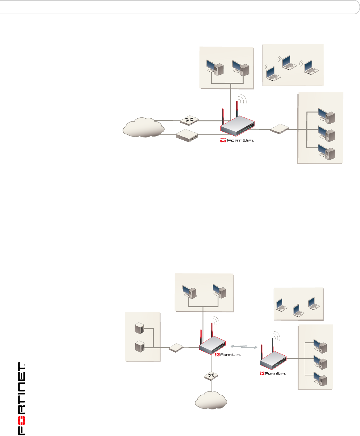
Access Point mode
When using the FortiWiFi in Access Point mode, the device acts as an access
point for wireless users to connect to, send and receive information over a
wireless network. It enables multiple wireless network users access to the
network without the need to connect to it physically. The FortiWiFi-50B can
connect to the internal network and act as a firewall to the Internet. Access Point
mode is the default mode.
FortiGate-50A/50B, FortiWiFi-50B and FortiGate-100 FortiOS 3.0 MR4 Install Guide
62 01-30004-0265-20070522
FortiWiFi-50B operation modes Using a wireless network
Figure 14: FortiWiFi in Access Point mode
Client mode
When using the FortiWiFi-50B in Client mode, the device is set to receive
transmissions from another access point. This enables you to connect remote
users to an existing network using wireless protocols from a location that does not
have a wired infrastructure.
For example, in a warehouse where shipping and receiving are on opposite sides
of the building, running cables is not an option due to the warehouse environment.
The FortiWiFi-50B unit can support wired users using its four Ethernet ports and
can connect to another Access Point wirelessly as a Client. This connects the
wired users to the network using the 802.11 wireless standard as a backbone.
Figure 15: FortiWiFi-50B in Client mode
DMZ
Network
Internal
Network
Internet
MODEM / DSL / Cable
Router
Internal
DMZ
WAN2
WAN1
Wireless Network
Internet
Wireless Network
Internal
Network
Internal
Network
Router
DMZ network
Web Server
Mail Server Hub or switch
Internal
DMZ
WAN1

Using a wireless network Setting up the FortiWiFi-50B as an Access Point
FortiGate-50A/50B, FortiWiFi-50B and FortiGate-100 FortiOS 3.0 MR4 Install Guide
01-30004-0265-20070522 63
Changing the operating mode
To change the wireless operating mode
1Go to System > Wireless > Settings.
2For the Operation mode, select Change
3Select the desired operation mode and select OK.
Setting up the FortiWiFi-50B as an Access Point
This section describes how to quickly configure the FortiWiFi-50B unit as an AP to
allow network access for wireless workstations located on the same wireless LAN
as the unit. It also describes how to configure firewall policies and wireless
security features to provide a secure wireless environment. For initial setup, use a
desktop computer on the internal network with TCP/IP set as a DHCP client
This section contains the following steps:
•Set the DHCP settings
•Set the security options
•Configure the firewall policies
Set the DHCP settings
Configure a DHCP server for the FortiWiFi-50B WLAN interface. As a DHCP
server, the interface dynamically assigns IP addresses to hosts on the network
connected to the WLAN interface.
To configure the FortiWiFi-50B to be a DHCP server
1Go to System > DHCP > Service.
2Select the blue triangle to expand the WLAN options.
3Configure the DHCP server settings:
4Select OK.
Name: Enter a name of the DHCP sever. For example, DHCPSever_1.
Enable: Select to enable the DHCP Server.
Type: Select regular unless you are configuring for remote clients who
will have an IPSec VPN connection to the WLAN interface.
IP Range: Enter the IP address of the WLAN to configure the IP address
range. For example, 10.10.80.1 to 10.10.80.20.
Network Mask: Enter the network mask you created in Table 12 on page 36.
Domain: Enter domain name, for example, www.fortinet.com.
Lease Time: The expiry date of an IP address. This feature specifies either an
unlimited or limited timeframe of an IP address.
Advanced: Use only to specify several DNS servers. This is the DNS that the
wireless clients will use when accessing the Internet.
Note: The IP range must match the subnet address of the network where the DHCP
request was received. Usually this would be the subnet connected to the WLAN interface.

FortiGate-50A/50B, FortiWiFi-50B and FortiGate-100 FortiOS 3.0 MR4 Install Guide
64 01-30004-0265-20070522
Setting up the FortiWiFi-50B as an Access Point Using a wireless network
Set the security options
To ensure proper security and protection of your network and its information, set
the security options for the FortiWiFi-50B unit.
To set the data security
1Go to System > Wireless > Settings.
2Enter an SSID.
3Set the SSID Broadcast to either enable or disable.
4Select a Security mode.
5Enter a key or pre-shared key depending on the Security Mode selected.
6Select the MAC Filter tab.
7Enable MAC filtering if desired.
8Enter the MAC addresses and select to Allow or Deny.
Configure the firewall policies
The FortiWiFi-50B provides WAN interfaces for Internet connections. You can
configure the Internet connection for both wired networks and the wireless
network through the WLAN interface.
You can provide secure Internet access for wireless clients by creating firewall
policies from the WLAN interface to the WAN1 or WAN2 interfaces.
The following example creates a policy from the wireless clients (WLAN interface)
to the Internet (WAN1 interface) using traffic shaping, firewall authentication and
the default Strict content policy.
To create a new wall policy for a secure Internet connection
1Go to Firewall > Policy.
2Select the blue arrow for WLAN to WAN1.
3Select Create New.
4Configure the following settings and select OK:
Note: You will need to distribute the information entered in step 2 and step 5 with the
wireless users so they can connect to the wireless network. It is highly recommended you
do not select “None”. Selecting None will leave your wireless network prone to hackers.
Interface/Zone Source WLAN
Interface/Zone Destination WAN1
Address Name Source All
Address Name Destination All
Schedule Always
Service ANY
Action ACCEPT
NAT Enable
Protection Profile Strict

FortiGate Firmware Upgrading to a new firmware version
FortiGate-50A/50B, FortiWiFi-50B and FortiGate-100 FortiOS 3.0 MR4 Install Guide
01-30004-0265-20070522 65
FortiGate Firmware
Fortinet periodically updates the FortiGate firmware to include enhancements and
address issues. After you have registered your FortiGate unit, FortiGate firmware
is available for download at http://support.fortinet.com.
Only the FortiGate administrators (whose access profiles contain system
configuration read and write privileges) and the FortiGate admin user can change
the FortiGate firmware.
This section includes the following topics:
•Upgrading to a new firmware version
•Reverting to a previous firmware version
•Installing firmware images from a system reboot using the CLI
•The FortiUSB key
•Testing a new firmware image before installing it
•Installing and using a backup firmware image (FortiGate-100 only)
Upgrading to a new firmware version
Use the web-based manager or CLI procedure to upgrade to a new FortiOS
firmware version or to a more recent build of the same firmware version.
Upgrading the firmware using the web-based manager
Use the following procedures to upgrade the FortiGate unit to a new firmware
version.
To upgrade the firmware using the web-based manager
1Copy the firmware image file to your management computer.
2Log into the web-based manager as the admin administrative user.
3Go to System > Status.
4Under System Information > Firmware Version, select Update.
Note: If you have an earlier version of the FortiOS firmware, for example FortiOS v2.50,
upgrade to FortiOS v2.80MR11 before upgrading to FortiOS v3.0.
Note: Installing firmware replaces your current antivirus and attack definitions, along with
the definitions included with the firmware release you are installing. After you install new
firmware, make sure that antivirus and attack definitions are up to date. For details see the
FortiGate Administration Guide.
Note: To use this procedure, you must log in using the admin administrator account, or an
administrator account that has system configuration read and write privileges.

FortiGate-50A/50B, FortiWiFi-50B and FortiGate-100 FortiOS 3.0 MR4 Install Guide
66 01-30004-0265-20070522
Upgrading to a new firmware version FortiGate Firmware
5Type the path and filename of the firmware image file, or select Browse and locate
the file.
6Select OK.
The FortiGate unit uploads the firmware image file, upgrades to the new firmware
version, restarts, and displays the FortiGate login. This process takes a few
minutes.
7Log into the web-based manager.
8Go to System > Status and check the Firmware Version to confirm the firmware
upgrade is successfully installed.
9Update antivirus and attack definitions. For information about updating antivirus
and attack definitions, see the FortiGate Administration Guide.
Upgrading the firmware using the CLI
To use the following procedure, you must have a TFTP server the FortiGate unit
can connect to.
To upgrade the firmware using the CLI
1Make sure the TFTP server is running.
2Copy the new firmware image file to the root directory of the TFTP server.
3Log into the CLI.
4Make sure the FortiGate unit can connect to the TFTP server.
You can use the following command to ping the computer running the TFTP
server. For example, if the IP address of the TFTP server is 192.168.1.168:
execute ping 192.168.1.168
5Enter the following command to copy the firmware image from the TFTP server to
the FortiGate unit:
execute restore image <name_str> <tftp_ipv4>
Where <name_str> is the name of the firmware image file and <tftp_ip> is the
IP address of the TFTP server. For example, if the firmware image file name is
image.out and the IP address of the TFTP server is 192.168.1.168, enter:
execute restore image.out 192.168.1.168
The FortiGate unit responds with the message:
This operation will replace the current firmware version!
Do you want to continue? (y/n)
6Type y.
Note: Installing firmware replaces your current antivirus and attack definitions0, along with
the definitions included with the firmware release you are installing. After you install new
firmware, use the procedure make sure that antivirus and attack definitions are up to date.
You can also use the CLI command execute update-now to update the antivirus and
attack definitions. For details, see the FortiGate Administration Guide.
Note: To use this procedure, you must log in using the admin administrator account, or an
administrator account that has system configuration read and write privileges.

FortiGate Firmware Reverting to a previous firmware version
FortiGate-50A/50B, FortiWiFi-50B and FortiGate-100 FortiOS 3.0 MR4 Install Guide
01-30004-0265-20070522 67
The FortiGate unit uploads the firmware image file, upgrades to the new firmware
version, and restarts. This process takes a few minutes.
7Reconnect to the CLI.
8To confirm the new firmware image is successfully installed, enter:
get system status
9Update antivirus and attack definitions (see the FortiGate Administration Guide),
or from the CLI, enter:
execute update-now
Reverting to a previous firmware version
Use the following procedures to revert your FortiGate unit to a previous firmware
version.
Use the web-based manager or CLI procedure to revert to a previous firmware
version. This procedure reverts the FortiGate unit to its factory default
configuration.
Reverting to a previous firmware version using the web-based manager
The following procedures revert the FortiGate unit to its factory default
configuration and deletes IPS custom signatures, web content lists, email filtering
lists, and changes to replacement messages.
Before beginning this procedure, it is recommended that you:
• back up the FortiGate unit configuration
• back up the IPS custom signatures
• back up web content and email filtering lists
For information, see the FortiGate Administration Guide.
If you are reverting to a previous FortiOS version (for example, reverting from
FortiOS v3.0 to FortiOS v2.80), you might not be able to restore the previous
configuration from the backup configuration file.
To revert to a previous firmware version using the web-based manager
1Copy the firmware image file to the management computer.
2Log into the FortiGate web-based manager.
3Go to System > Status.
4Under System Information > Firmware Version, select Update.
5Type the path and filename of the firmware image file, or select Browse and locate
the file.
Note: Installing firmware replaces the current antivirus and attack definitions, along with the
definitions included with the firmware release you are installing. After you install new
firmware, make sure that antivirus and attack definitions are up to date. For details, see the
FortiGate Administration Guide.
Note: To use this procedure, you must log in using the admin administrator account, or an
administrator account that has system configuration read and write privileges.

FortiGate-50A/50B, FortiWiFi-50B and FortiGate-100 FortiOS 3.0 MR4 Install Guide
68 01-30004-0265-20070522
Reverting to a previous firmware version FortiGate Firmware
6Select OK.
The FortiGate unit uploads the firmware image file, reverts to the old firmware
version, resets the configuration, restarts, and displays the FortiGate login. This
process takes a few minutes.
7Log into the web-based manager.
8Go to System > Status and check the Firmware Version to confirm that the
firmware is successfully installed.
9Restore your configuration.
For information about restoring your configuration, see the FortiGate
Administration Guide.
10 Update antivirus and attack definitions.
For information about antivirus and attack definitions, see the FortiGate
Administration Guide.
Reverting to a previous firmware version using the CLI
This procedure reverts the FortiGate unit to its factory default configuration and
deletes IPS custom signatures, web content lists, email filtering lists, and changes
to replacement messages.
Before beginning this procedure you can:
• back up the FortiGate unit system configuration using the command execute
backup config
• back up the IPS custom signatures using the command execute backup
ipsuserdefsig
• back up web content and email filtering lists
For information, see the FortiGate Administration Guide.
If you are reverting to a previous FortiOS version (for example, reverting from
FortiOS v3.0 to FortiOS v2.80), you might not be able to restore your previous
configuration from the backup configuration file.
To use the following procedure, you must have a TFTP server the FortiGate unit
can connect to.
To revert to a previous firmware version using the CLI
1Make sure the TFTP server is running.
2Copy the firmware image file to the root directory of the TFTP server.
3Log into the FortiGate CLI.
Note: Installing firmware replaces the current antivirus and attack definitions, along with the
definitions included with the firmware release you are installing. After you install new
firmware, use the procedure o make sure that antivirus and attack definitions are up to date.
For details, see the FortiGate Administration Guide. You can also use the CLI command
execute update-now to update the antivirus and attack definitions.
Note: To use this procedure, you must log in using the admin administrator account, or an
administrator account that has system configuration read and write privileges.

FortiGate Firmware Reverting to a previous firmware version
FortiGate-50A/50B, FortiWiFi-50B and FortiGate-100 FortiOS 3.0 MR4 Install Guide
01-30004-0265-20070522 69
4Make sure the FortiGate unit can connect to the TFTP server.
You can use the following command to ping the computer running the TFTP
server. For example, if the TFTP server's IP address is 192.168.1.168:
execute ping 192.168.1.168
5Enter the following command to copy the firmware image from the TFTP server to
the FortiGate unit:
execute restore image <name_str> <tftp_ipv4>
Where <name_str> is the name of the firmware image file and <tftp_ip> is
the IP address of the TFTP server. For example, if the firmware image file name is
v2.80image.com and the IP address of the TFTP server is 192.168.1.168,
enter:
execute restore v2.80image.out 192.168.1.168
The FortiGate unit responds with the message:
This operation will replace the current firmware version!
Do you want to continue? (y/n)
6Type y.
The FortiGate unit uploads the firmware image file. After the file uploads, a
message similar to the following is displayed:
Get image from tftp server OK.
Check image OK.
This operation will downgrade the current firmware version!
Do you want to continue? (y/n)
7Type y.
The FortiGate unit reverts to the old firmware version, resets the configuration to
factory defaults, and restarts. This process takes a few minutes.
8Reconnect to the CLI.
9To confirm the new firmware image has been loaded, enter:
get system status
10 To restore your previous configuration, if needed, use the command:
execute restore config <name_str> <tftp_ipv4>
11 Update antivirus and attack definitions.
For information, see the FortiGate Administration Guide, or from the CLI, enter:
execute update-now

FortiGate-50A/50B, FortiWiFi-50B and FortiGate-100 FortiOS 3.0 MR4 Install Guide
70 01-30004-0265-20070522
Installing firmware images from a system reboot using the CLI FortiGate Firmware
Installing firmware images from a system reboot using the CLI
This procedure installs a specified firmware image and resets the FortiGate unit to
default settings. You can use this procedure to upgrade to a new firmware
version, revert to an older firmware version, or re-install the current firmware
version.
Use this procedure to install a new firmware version or revert to a previous
firmware version. To use this procedure, you must connect to the CLI using the
FortiGate console port and a RJ-45 to DB-9 or null-modem cable. This procedure
reverts the FortiGate unit to its factory default configuration.
For this procedure you:
• Access the CLI by connecting to the FortiGate console port using a
null-modem cable.
• Install a TFTP server that you can connect to from the FortiGate internal
interface. The TFTP server should be on the same subnet as the internal
interface.
Before beginning this procedure you can:
• back up the FortiGate unit configuration
• back up the IPS custom signatures
• back up web content and email filtering lists
For information, see the FortiGate Administration Guide.
If you are reverting to a previous FortiOS version (for example, reverting from
FortiOS v3.0 to FortiOS v2.80), you might not be able to restore your previous
configuration from the backup configuration file.
To install firmware from a system reboot
1Connect to the CLI using the null-modem cable and FortiGate console port.
2Make sure the TFTP server is running.
3Copy the new firmware image file to the root directory of the TFTP server.
4Make sure the internal interface is connected to the same network as the TFTP
server.
5To confirm the FortiGate unit can connect to the TFTP server, use the following
command to ping the computer running the TFTP server. For example, if the IP
address of the TFTP server is 192.168.1.168, enter:
execute ping 192.168.1.168
Note: This procedure varies for different FortiGate BIOS versions. These variations are
explained in the procedure steps that are affected. The version of the BIOS running on the
FortiGate unit is displayed when you restart the FortiGate unit using the CLI through a
console connection.
Note: Installing firmware replaces the current antivirus and attack definitions, along with
the definitions included with the firmware release you are installing. After you install new
firmware, use the procedure make sure that antivirus and attack definitions are up to date.
For information, see the FortiGate Administration Guide.

FortiGate Firmware Installing firmware images from a system reboot using the CLI
FortiGate-50A/50B, FortiWiFi-50B and FortiGate-100 FortiOS 3.0 MR4 Install Guide
01-30004-0265-20070522 71
6Enter the following command to restart the FortiGate unit:
execute reboot
The FortiGate unit responds with the following message:
This operation will reboot the system !
Do you want to continue? (y/n)
7Type y.
As the FortiGate units starts, a series of system startup messages is displayed.
When one of the following messages appears:
• FortiGate unit running v2.x BIOS
Press Any Key To Download Boot Image.
...
• FortiGate unit running v3.x BIOS
Press any key to display configuration menu.......
Immediately press any key to interrupt the system startup.
If you successfully interrupt the startup process, one of the following messages
appears:
• FortiGate unit running v2.x BIOS
Enter TFTP Server Address [192.168.1.168]:
Go to step 9.
• FortiGate unit running v3.x BIOS
[G]: Get firmware image from TFTP server.
[F]: Format boot device.
[Q]: Quit menu and continue to boot with default
firmware.
[H]: Display this list of options.
Enter G,F,Q,or H:
8Type G to get the new firmware image from the TFTP server.
The following message appears:
Enter TFTP server address [192.168.1.168]:
9Type the address of the TFTP server and press Enter.
The following message appears:
Enter Local Address [192.168.1.188]:
10 Type an IP address that can be used by the FortiGate unit to connect to the FTP
server.
The IP address can be any IP address that is valid for the network the interface is
connected to. Make sure you do not enter the IP address of another device on this
network.
The following message appears:
Enter File Name [image.out]:
Note: You have only 3 seconds to press any key. If you do not press a key soon enough,
the FortiGate unit reboots and you must log in and repeat the execute reboot
command.

FortiGate-50A/50B, FortiWiFi-50B and FortiGate-100 FortiOS 3.0 MR4 Install Guide
72 01-30004-0265-20070522
Installing firmware images from a system reboot using the CLI FortiGate Firmware
11 Enter the firmware image filename and press Enter.
The TFTP server uploads the firmware image file to the FortiGate unit and
messages similar to the following are displayed:
• FortiGate unit running v2.x BIOS
Do You Want To Save The Image? [Y/n]
Type Y.
• FortiGate unit running v3.x BIOS
Save as Default firmware/Run image without saving:[D/R]
or
Save as Default firmware/Backup firmware/Run image without
saving:[D/B/R]
12 Type D.
The FortiGate unit installs the new firmware image and restarts. The installation
might take a few minutes to complete.
Restoring the previous configuration
Change the internal interface address, if required. You can do this from the CLI
using the following command:
config system interface
edit internal
set ip <address_ipv4mask>
set allowaccess {ping https ssh telnet http}
end
After changing the interface address, you can access the FortiGate unit from the
web-based manager and restore the configuration.
For more information, see the FortiGate Administration Guide.
If you are reverting to a previous firmware version (for example, reverting from
FortiOS v3.0 to FortiOS v2.80), you might not be able to restore your previous
configuration from the backup up configuration file.

FortiGate Firmware The FortiUSB key
FortiGate-50A/50B, FortiWiFi-50B and FortiGate-100 FortiOS 3.0 MR4 Install Guide
01-30004-0265-20070522 73
The FortiUSB key
The FortiUSB key provides flexibility and control when you are backing up and
restoring configuration files. The FortiUSB key also enables you to have a single,
secure location for storing configuration files.
The FortiUSB key is used with the USB Auto-Install feature, automatically
installing a configuration file and a firmware image file on a system reboot. The
USB Auto-Install feature uses a configuration file and a firmware image file that is
on the FortiUSB key, and on a system reboot, checks if these files need to be
installed. If they do, the FortiGate unit installs the configuration file and firmware
image file directly from the key to the unit.
Backup and Restore from the FortiUSB key
Use the FortiUSB key to backup a configuration file or restore a configuration file.
You should always make sure the FortiUSB key is properly installed before
proceeding since the FortiGate unit must recognize that the key is installed in its
USB port.
To backup a FortiGate configuration using the web-based manager
1Go to System > Maintenance > Backup and Restore.
2Select USB Disk from the Backup configuration to list.
3Select Backup.
If you want to encrypt the configuration file, select Encrypt configuration file and
enter a password, then select Backup. The password is also used when you are
restoring the configuration file.
To restore configuration using the web-based manager
1Go to System > Maintenance > Backup and Restore.
2Select USB Disk from the Restore configuration from list.
3Select the configuration file you want restored in the Filename list.
If you have a password for the configuration file, enter it in the Password field.
4Select Restore.
To backup configuration using the CLI
1Log into the CLI.
2Enter the following command to backup the configuration files:
Note: The FortiUSB key requires a USB interface on the FortiGate unit. The FortiGate-50A,
FortiGate-50B and FortiWiFi-50B include USB interfaces.
Note: The FortiUSB key is purchased separately. The FortiGate unit only supports the
FortiUSB key, available from Fortinet.
Note: You can only save VPN certificates if you encrypt the file. Make sure the
configuration encryption is enabled so you can save the VPN certificates with the
configuration file. However, an encrypted file is ineffective if selected for the Auto-Install
feature.

FortiGate-50A/50B, FortiWiFi-50B and FortiGate-100 FortiOS 3.0 MR4 Install Guide
74 01-30004-0265-20070522
The FortiUSB key FortiGate Firmware
exec backup config usb <filename>
3Enter the following command to verify the configuration files are on the key:
exec usb-disk list
To restore configuration using the CLI
1Log into the CLI.
2Enter the following command to restore the configuration files:
exec restore config usb <filename>
The FortiGate unit responds with the following message:
This operation will replace the current firmware version!
Do you want to continue? (y/n)
3Type y.
Using the USB Auto-Install feature
The USB Auto-Install feature automatically updates the FortiGate configuration
file and image file on a system reboot. Also, this feature provides you with an
additional backup if you are unable to save your system settings before shutting
down or rebooting your FortiGate unit.
The following procedures use both the web-based manager and the CLI.
However, it is recommended you use the CLI since the login screen may appear
before the installation is complete. The FortiGate unit may reboot twice if installing
the firmware image and configuration file.
To configure the USB Auto-Install using the web-based manager
1Go to System > Maintenance > Backup and Restore.
2Select the blue arrow to expand the Advanced options.
3Select the following:
• On system restart, automatically update FortiGate configuration file if default
file name is available on the USB disk.
• On system restart, automatically update FortiGate firmware image if default
image is available on the USB disk.
4Enter the configuration and image filenames or use the default configuration
filename (fgt_system.conf) and default image name (image.out).
5Select Apply.
To configure the USB Auto-Install using the CLI
1Log into the CLI.
2Enter the following command:
Note: You need an unencrypted configuration file for this feature. Also the default files,
image.out and fgt_system.conf, must be in the root directory.
Note: Make sure FortiOS 3.0MR1 is installed on the FortiGate unit before installing.

FortiGate Firmware Testing a new firmware image before installing it
FortiGate-50A/50B, FortiWiFi-50B and FortiGate-100 FortiOS 3.0 MR4 Install Guide
01-30004-0265-20070522 75
config system auto-install
set default-config-file <filename>
set auto-install-config <enable/disable>
set default-image-file <filename>
set auto-install-image <enable/disable>
end
Additional CLI commands for the FortiUSB key
Use the following CLI commands when you want to delete a file from the FortiUSB
key, list what files are on the key, including formatting the key or renaming a file:
• exec usb-disk list
• exec usb-disk delete <filename>
• exec usb-disk format
• exec usb-disk rename <old_filename1> <old_filename2>
Testing a new firmware image before installing it
You can test a new firmware image by installing the firmware image from a
system reboot and saving it to system memory. After completing this procedure,
the FortiGate unit operates using the new firmware image with the current
configuration. This new firmware image is not permanently installed. The next
time the FortiGate unit restarts, it operates with the originally installed firmware
image using the current configuration. If the new firmware image operates
successfully, you can install it permanently using the procedure “Upgrading to a
new firmware version” on page 65.
Use this procedure to test a new firmware image before installing it. To use this
procedure, you must connect to the CLI using the FortiGate console port and a
RJ-45 to DB-9 or null-modem cable. This procedure temporarily installs a new
firmware image using your current configuration.
For this procedure you:
• Access the CLI by connecting to the FortiGate console port using a RJ-45 to
DB-9 serial cable or null-modem cable.
• Install a TFTP server that you can connect to from the FortiGate internal
interface. The TFTP server should be on the same subnet as the internal
interface.
To test a new firmware image
1Connect to the CLI using a RJ-45 to DB-9 serial cable or a null-modem cable and
FortiGate console port.
2Make sure the TFTP server is running.
3Copy the new firmware image file to the root directory of the TFTP server.
Note: If you are trying to delete a configuration file from the CLI, and the filename contains
spaces, you will need quotations around the filename before you can delete the file from the
FortiUSB key.

FortiGate-50A/50B, FortiWiFi-50B and FortiGate-100 FortiOS 3.0 MR4 Install Guide
76 01-30004-0265-20070522
Testing a new firmware image before installing it FortiGate Firmware
4Make sure the internal interface is connected to the same network as the TFTP
server.
You can use the following command to ping the computer running the TFTP
server. For example, if the TFTP server's IP address is 192.168.1.168:
execute ping 192.168.1.168
5Enter the following command to restart the FortiGate unit:
execute reboot
6As the FortiGate unit reboots, press any key to interrupt the system startup.
As the FortiGate units starts, a series of system startup messages are displayed.
When one of the following messages appears:
• FortiGate unit running v2.x BIOS
Press Any Key To Download Boot Image.
...
• FortiGate unit running v3.x BIOS
Press any key to display configuration menu........
7Immediately press any key to interrupt the system startup.
If you successfully interrupt the startup process, one of the following messages
appears:
• FortiGate unit running v2.x BIOS
Enter TFTP Server Address [192.168.1.168]:
Go to step 9.
• FortiGate unit running v3.x BIOS
[G]: Get firmware image from TFTP server.
[F]: Format boot device.
[Q]: Quit menu and continue to boot with default
firmware.
[H]: Display this list of options.
Enter G,F,Q,or H:
8Type G to get the new firmware image from the TFTP server.
The following message appears:
Enter TFTP server address [192.168.1.168]:
9Type the address of the TFTP server and press Enter.
The following message appears:
Enter Local Address [192.168.1.188]:
Note: You have only 3 seconds to press any key. If you do not press a key soon enough,
the FortiGate unit reboots and you must log in and repeat the execute reboot
command.

FortiGate Firmware Installing and using a backup firmware image
FortiGate-50A/50B, FortiWiFi-50B and FortiGate-100 FortiOS 3.0 MR4 Install Guide
01-30004-0265-20070522 77
10 Type an IP address that can be used by the FortiGate unit to connect to the FTP
server.
The IP address can be any IP address that is valid for the network the interface is
connected to. Make sure you do not enter the IP address of another device on this
network.
The following message appears:
Enter File Name [image.out]:
11 Enter the firmware image file name and press Enter.
The TFTP server uploads the firmware image file to the FortiGate unit and
messages similar to the following appear.
• FortiGate unit running v2.x BIOS
Do You Want To Save The Image? [Y/n]
Type N.
• FortiGate unit running v3.x BIOS
Save as Default firmware/Run image without saving:[D/R]
or
Save as Default firmware/Backup firmware/Run image without
saving:[D/B/R]
12 Type R.
The FortiGate image is installed to system memory and the FortiGate unit starts
running the new firmware image but with its current configuration.
13 You can log into the CLI or the web-based manager using any administrative
account.
14 To confirm the new firmware image has been loaded, from the CLI enter:
get system status
You can test the new firmware image as required.
Installing and using a backup firmware image
If the FortiGate unit is running BIOS version v3.x, you can install a backup
firmware image. Once the backup firmware image is installed you can switch to
this backup image when required.
Installing a backup firmware image
To run this procedure you:
The following procedures are specific to the FortiGate-100, FortiGate-50B and
FortiWiFi-50B.
100
50B
WiFi-50B

FortiGate-50A/50B, FortiWiFi-50B and FortiGate-100 FortiOS 3.0 MR4 Install Guide
78 01-30004-0265-20070522
Installing and using a backup firmware image FortiGate Firmware
• Access the CLI by connecting to the FortiGate console port using a RJ-45 to
DB-9 serial cable or null-modem cable.
• Install a TFTP server that you can connect to from the FortiGate as described
in the procedure “Installing firmware images from a system reboot using the
CLI” on page 70.
To install a backup firmware image
1Connect to the CLI using a RJ-45 or DB-9 serial cable or a null-modem cable and
FortiGate console port.
2Make sure the TFTP server is running.
3Copy the new firmware image file to the root directory of your TFTP server.
4To confirm the FortiGate unit can connect to the TFTP server, use the following
command to ping the computer running the TFTP server. For example, if the IP
address of the TFTP server is 192.168.1.168:
execute ping 192.168.1.168
5Enter the following command to restart the FortiGate unit:
execute reboot
As the FortiGate unit starts, a series of system startup messages are displayed.
When of the following message appears:
Press any key to enter configuration menu........
6Immediately press any key to interrupt the system startup.
If you successfully interrupt the startup process, the following message appears:
[G]: Get firmware image from TFTP server.
[F]: Format boot device.
[Q]: Quit menu and continue to boot with default firmware.
[H]: Display this list of options.
Enter G,F,Q,or H:
7Type G to get the new firmware image from the TFTP server.
The following message appears:
Enter TFTP server address [192.168.1.168]:
8Type the address of the TFTP server and press Enter.
The following message appears:
Enter Local Address [192.168.1.188]:
Note: You have only 3 seconds to press any key. If you do not press a key soon enough,
the FortiGate unit reboots and you must log in and repeat the execute reboot
command.

FortiGate Firmware Installing and using a backup firmware image
FortiGate-50A/50B, FortiWiFi-50B and FortiGate-100 FortiOS 3.0 MR4 Install Guide
01-30004-0265-20070522 79
9Type an IP address that can be used by the FortiGate unit to connect to the FTP
server.
The IP address can be any IP address that is valid for the network the interface is
connected to. Make sure you do not enter the IP address of another device on this
network.
The following message appears:
Enter File Name [image.out]:
10 Enter the firmware image file name and press Enter.
The TFTP server uploads the firmware image file to the FortiGate unit and the
following message is displayed.
Save as Default firmware/Backup firmware/Run image without
saving:[D/B/R]
11 Type B.
The FortiGate unit saves the backup firmware image and restarts. When the
FortiGate unit restarts it is running the previously installed firmware version.

FortiGate-50A/50B, FortiWiFi-50B and FortiGate-100 FortiOS 3.0 MR4 Install Guide
80 01-30004-0265-20070522
Installing and using a backup firmware image FortiGate Firmware

Index
FortiGate-50A/50B, FortiWiFi-50B and FortiGate-100 FortiOS 3.0 MR4 Install Guide
01-30004-0265-20070522 81
Index
A
adding a default route 38, 41
C
CAT5 20
certificate, security 22
CLI
additional CLI commands, FortiUSB 75
connecting 23
upgrading the firmware 66, 68
comments, documentation 13
configuring
redundant mode 52
standalone mode 52
connecting
to the CLI 23
to the web-based manager 21
customer service 13
D
dead gateway detection 55
default
adding a route 38, 41
restoring settings 31
DHCP
configuration 37
documentation
commenting on 13
Fortinet 12
E
Ethernet, Power 20
F
factory defaults
DHCP server configuration 28
firewall configuration 29
NAT/Route mode config 28
protection profiles 30
Transparent mode config 29
firewall policies
modem 56
firmware
backup and restore from FortiUSB key 73
install, backup firmware image 77
installing 70
re-installing current version 70
restoring previous config 72
reverting to an older version 70
testing new firmware 75
upgrading to a new version 65
upgrading using the CLI 66, 68
upgrading using the web-base manager 31, 65, 67
FortiGate documentation
commenting on 13
Fortinet 9
Fortinet customer service 13
Fortinet documentation 12
Fortinet Family Products 9
FortiBridge 10
FortiClient 9
FortiGuard 9
FortiLog 10
FortiMail 9
FortiManager 10
FortiReporter 10
Fortinet Knowledge Center 13
FortiUSB key
additional CLI commands 75
backup and restore 73
USB Auto-Install 74
G
grounding 20
I
IEEE 802.3af 20
installing factory defaults 24
introduction
Fortinet documentation 12
L
LED descriptions 19
M
modem
adding firewall policies 56
redundant mode 51
standalone mode 51, 52
modem CLI commands
altmode 53
auto-dial 53
connect_timeout 53
dial-on-demand 53
holddown-timer 53
idle-timer 53
interface 53
mode 53
passwd1 53
passwd2 54
passwd3 54
peer_modem1 54
peer_modem2 54
phone1 54
phone2 54
phone3 54
redial 54
status 54
username1 54
username2 54
username3 54

FortiGate-50A/50B, FortiWiFi-50B and FortiGate-100 FortiOS 3.0 MR4 Install Guide
82 01-30004-0265-20070522
Index
mounting 19
N
NAT/Route mode
settings 36
using the CLI 39
using the web-based manager 37
NTP server 46
NTP server synchronize 46
P
ping requests, preventing public FortiGate interface
from responding to 35
ping server 55
PoE 20
Power over Ethernet 20
PPPoE configuration 37
products, Fortinet family 9
protection profiles, default 30
R
reconnecting to the web-based manager 45
redundant mode
configuring 52
modem 51
registering the FortiGate unit 8
restoring default settings 31
restoring previous firmware config 72
reverting, to an older firmware version 70
S
security certificate 22
set time 46
standalone mode
configuring 52
modem 51, 52
synchronize with NTP server 46
T
technical support 13
time zone 46
Transparent mode
changing to 44
settings 43
using the CLI 44
using web-based manager 43
U
updating
adding override server 49
antivirus and IPS, web-based manager 47
IPS using CLI 48
scheduling updates 48
upgrading
firmware 65
firmware using the CLI 66, 68
firmware using the web-based manager 31, 65, 67
USB Auto-Install feature 74
V
verifying
connection 41, 45, 46
connection, web-based manager 39
web-based manager connection 39
W
web-based manager, connecting 21