Fortress Technologies ES2440X Dual Radio Access Point/Bridge User Manual
Fortress Technologies, Inc. Dual Radio Access Point/Bridge
UserManual.wiki
>
Fortress Technologies
>
ES2440X User Manual
>
User Manual
Contents
1.
Marketing Literuature
2.
User Manual
3.
Marketing Literature
User Manual
Navigation menu
Upload a User Manual
Namespaces
Wiki Guide
HTML
PDF
Info
Views
User Manual
Discussion / Help
Navigation
![ES2440 Hardware Guidei009-00045-00r4Fortress ES2440 High-Capacity Infrastructure Mesh Point [rev.4a]Copyright © 2012 Fortress Technologies, Inc. All rights reserved.This document contains proprietary information protected by copyright. No part of this document may be reproduced or transmitted in any form or by any means, electronic or mechanical, without written permission of Fortress Technologies, 2 Technology Park Drive, Westford, MA 01886-3140, except as specified in the Product Warranty and License Terms.FORTRESS TECHNOLOGIES MAKES NO WARRANTY OF ANY KIND WITH REGARD TO THIS MATERIAL, INCLUDING BUT NOT LIMITED TO THE IMPLIED WARRANTIES OF MERCHANTABILITY AND FITNESS FOR A PARTICULAR PURPOSE. FORTRESS TECHNOLOGIES SHALL NOT BE LIABLE FOR ERRORS CONTAINED HEREIN OR FOR INCIDENTAL OR CONSEQUENTIAL DAMAGES IN CONNECTION WITH THE FURNISHING, PERFORMANCE OR USE OF THIS MATERIAL. THE INFORMATION IN THIS DOCUMENT IS SUBJECT TO CHANGE WITHOUT NOTICE.The General Dynamics C4 Systems | Fortress Technologies, Fortress Technologies and AirFortress logos and AirFortress and are registered trademarks. Multi-Factor Authentication, Unified Security Model, Wireless Link Layer Security and Three Factor Authentication (TFA) are trademarks of Fortress Technologies, Inc. The technology behind Wireless Link Layer Security™ enjoys U.S. and international patent protection under patent number 5,757,924.All trademarks mentioned in this document are the property of their respective owners.LIMITED WARRANTYHardwareFortress warrants the Hardware will be free of defects in material and workmanship under normal use. Fortress further warrants that the Hardware will conform to Specifications in effect on the date of shipment of the product, from Fortress location.SoftwareThe Limited Warranty as described in the Fortress End User License Agreement (EULA) sets forth Fortress’ warranty obligations with respect to Software. This End User License Agreement is included with the product or a copy may be obtained at the following URL: http://www.gdfortress.com/Support/general-support.htmlThis limited warranty extends only to the original purchaser of the Product.DURATION OF WARRANTYHardware and Software is warranted for a period of one (1) year commencing from the ship date to Purchaser [and in the case of resale by a Fortress Solution Provider, commencing not more than (90) days after original shipment by Fortress]. The date of shipment is established per the shipping document (packing list) for the Product that is shipped.REMEDIESPurchaser’s sole and exclusive remedy (within the warranty period) and the entire liability of Fortress and its suppliers under this limited warranty will be, after return to a Fortress repair facility, the repair and return of Product to Purchaser. At Fortress’ option if it is not able to repair the product, we will replace it with a comparable product that is new or refurbished. Purchaser shall pay expenses for return of such Products to Fortress. Fortress shall pay expenses for shipment of returned Products to Purchaser.WARRANTY EXCLUSIONSThe above Hardware and Software (EULA) limited warranty do not apply if the Hardware Product or Software or any other equipment upon which the Software is authorized by Fortress or its suppliers or licensors to be used (a) has been damaged through abuse or negligence or by accident, (b) has been altered except by an authorized Fortress representative, (c) has been subjected to abnormal physical or electrical stress (i.e., lightning strike) or abnormal environmental conditions, (d) has been lost or damaged in](https://usermanual.wiki/Fortress-Technologies/ES2440X.User-Manual/User-Guide-1815838-Page-2.png)
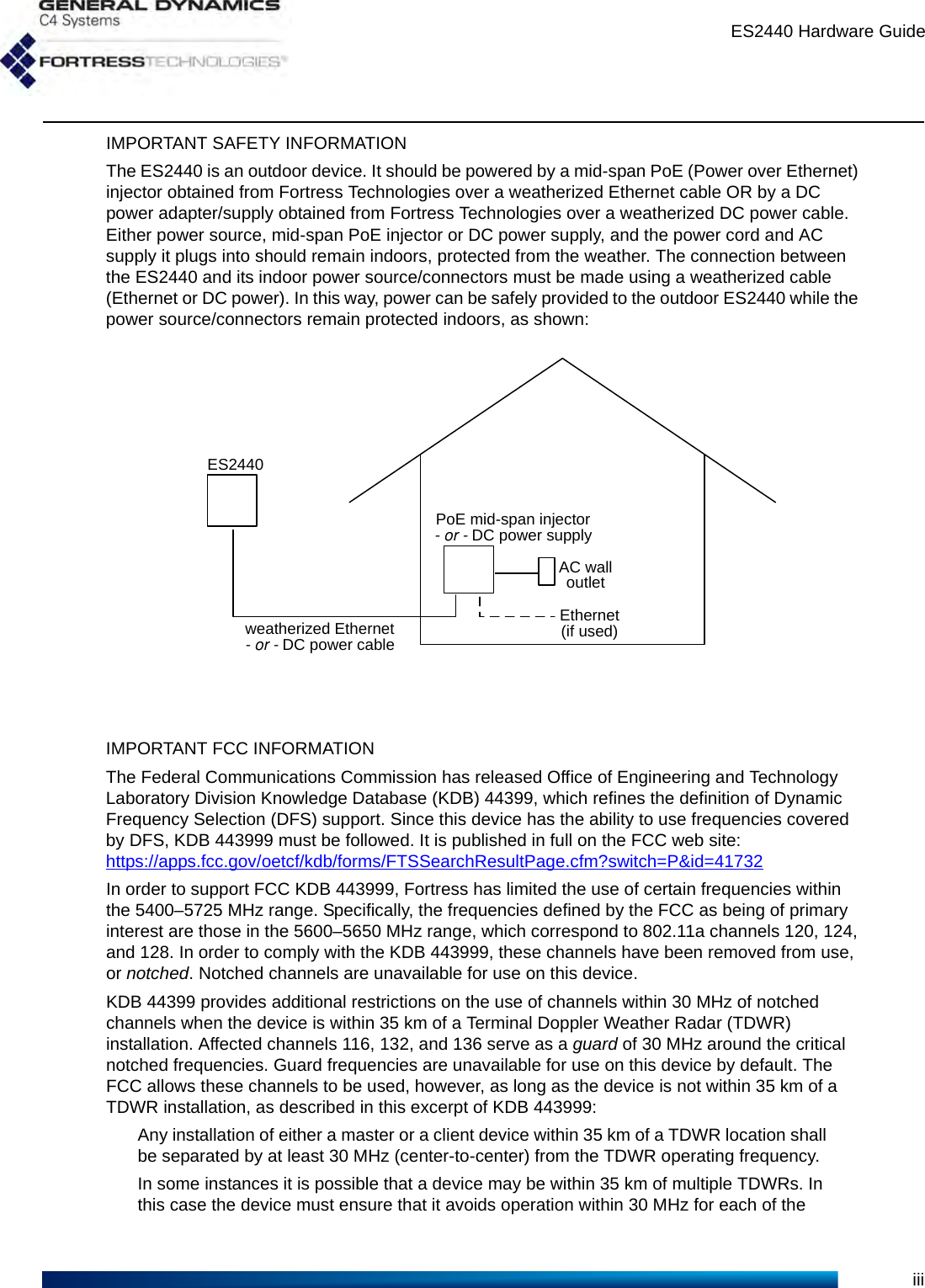
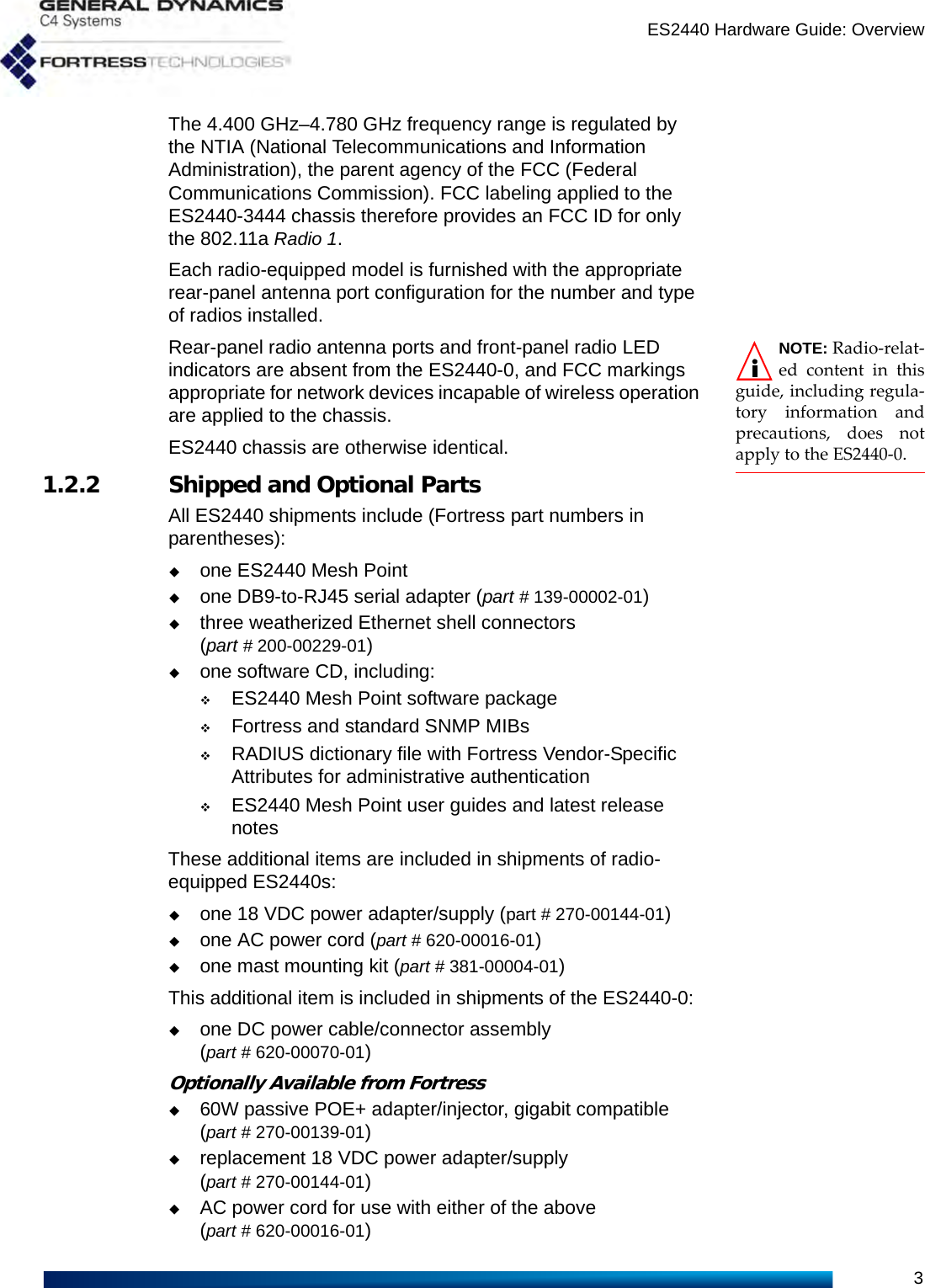
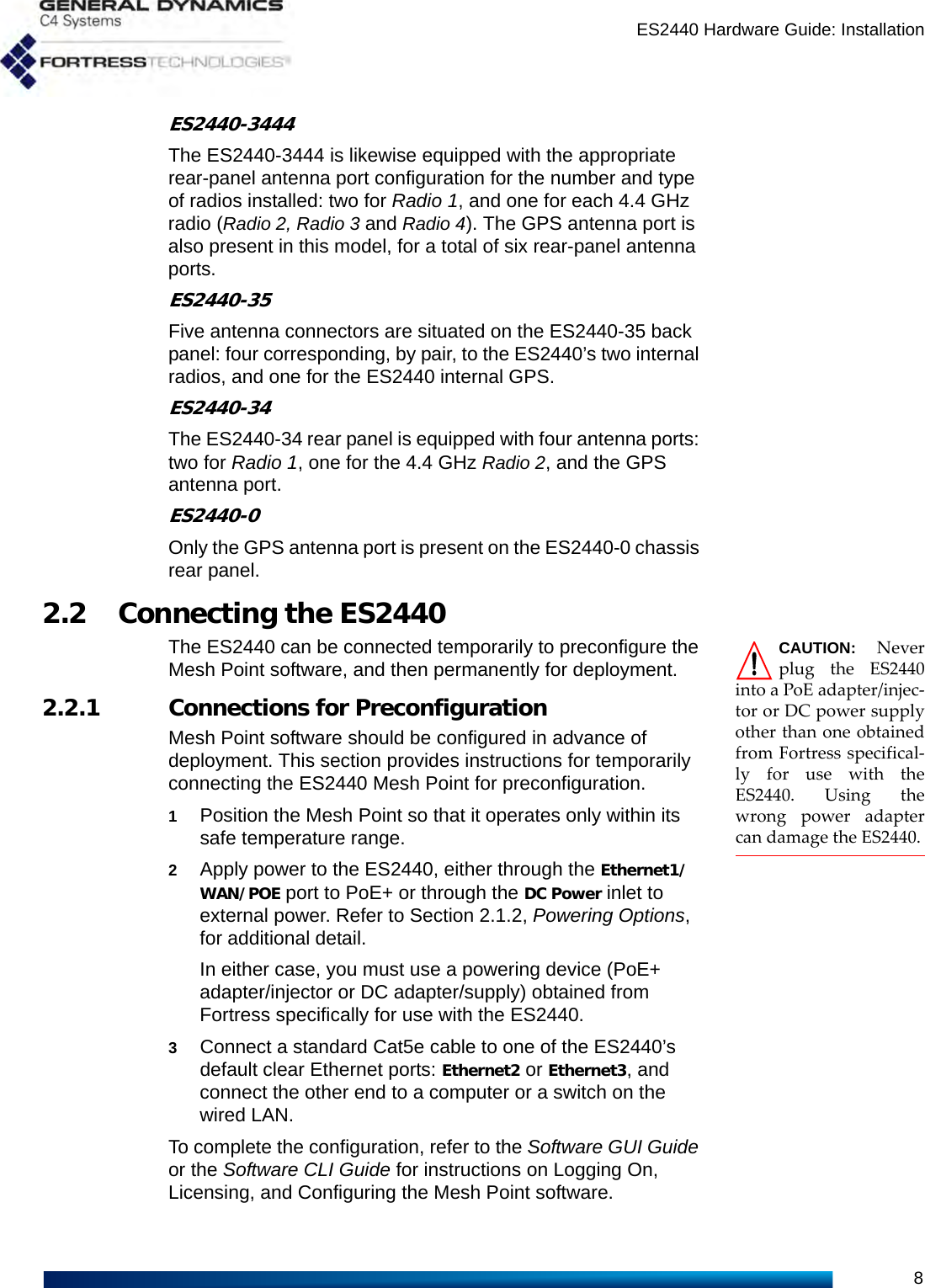
![ES2440 Hardware GuideivTDWRs. This requirement applies even if the master is outside the 35 km radius but communicates with outdoor clients which may be within the 35 km radius of the TDWRs.The requirement for ensuring 30 MHz frequency separation is based on the best information available to date. If interference is not eliminated, a distance limitation based on line-of-sight from TDWR will need to be used. Please refer to the original KDB 443999 as posted on the FCC web site for the complete text.In order to enable channels 116, 132, and/or 136, please contact Fortress to obtain a special license. This license will be issued after it is confirmed that the installation is not within 30 MHz and 35 km of registered TDWR sites. The following table (provided by the FCC in KDB 443999 published on 10/14/2010) describes the locations of TDWR sites, as well as the frequencies at which these sites operate:TDWR Location Information TERRAIN ELEVATION (MSL) [ft] ANTENNA HEIGHT ABOVE TERRAIN [ft] STATE CITY LONGITUDE LATITUDE FREQUENCY AZ PHOENIX W 112 09 46 N 33 25 14 5610 MHz 1024 64 CO DENVER W 104 31 35 N 39 43 39 5615 MHz 5643 64 FL FT LAUDERDALE W 080 20 39 N 26 08 36 5645 MHz 7 113 FL MIAMI W 080 29 28 N 25 45 27 5605 MHz 10 113 FL ORLANDO W 081 19 33 N 28 20 37 5640 MHz 72 97 FL TAMPA W 082 31 04 N 27 51 35 5620 MHz 14 80 FL WEST PALM BEACH W 080 16 23 N 26 41 17 5615 MHz 20 113 GA ATLANTA W 084 15 44 N 33 38 48 5615 MHz 962 113 IL MCCOOK W 087 51 31 N 41 47 50 5615 MHz 646 97 IL CRESTWOOD W 087 43 47 N 41 39 05 5645 MHz 663 113 IN INDIANAPOLIS W 086 26 08 N 39 38 14 5605 MHz 751 97 KS WICHITA W 097 26 13 N 37 30 26 5603 MHz 1270 80 KY COVINGTON CINCINNATI W 084 34 48 N 38 53 53 5610 MHz 942 97 KY LOUISVILLE W 085 36 38 N 38 02 45 5646 MHz 617 113 LA NEW ORLEANS W 090 24 11 N 30 01 18 5645 MHz 2 97 MA BOSTON W 070 56 01 N 42 09 30 5610 MHz 151 113 MD BRANDYWINE W 076 50 42 N 38 41 43 5635 MHz 233 113 MD BENFIELD W 076 37 48 N 39 05 23 5645 MHz 184 113 MD CLINTON W 076 57 43 N 38 45 32 5615 MHz 249 97 MI DETROIT W 083 30 54 N 42 06 40 5615 MHz 656 113 MN MINNEAPOLIS W 092 55 58 N 44 52 17 5610 MHz 1040 80 MO KANSAS CITY W 094 44 31 N 39 29 55 5605 MHz 1040 64 MO SAINT LOUIS W 090 29 21 N 38 48 20 5610 MHz 551 97 MS DESOTO COUNTY W 089 59 33 N 34 53 45 5610 MHz 371 113 NC CHARLOTTE W 080 53 06 N 35 20 14 5608 MHz 757 113 NC RALEIGH DURHAM W 078 41 50 N 36 00 07 5647 MHz 400 113 NJ WOODBRIDGE W 074 16 13 N 40 35 37 5620 MHz 19 113 NJ PENNSAUKEN W 075 04 12 N 39 56 57 5610 MHz 39 113 NV LAS VEGAS W 115 00 26 N 36 08 37 5645 MHz 1995 64 NY FLOYD BENNETT FIELD W 073 52 49 N 40 35 20 5647 MHz 8 97 OH DAYTON W 084 07 23 N 40 01 19 5640 MHz 922 97 OH CLEVELAND W 082 00 28 N 41 17 23 5645 MHz 817 113 OH COLUMBUS W 082 42 55 N 40 00 20 5605 MHz 1037 113 OK AERO. CTR TDWR #1 W 097 37 31 N 35 24 19 5610 MHz 1285 80](https://usermanual.wiki/Fortress-Technologies/ES2440X.User-Manual/User-Guide-1815838-Page-5.png)
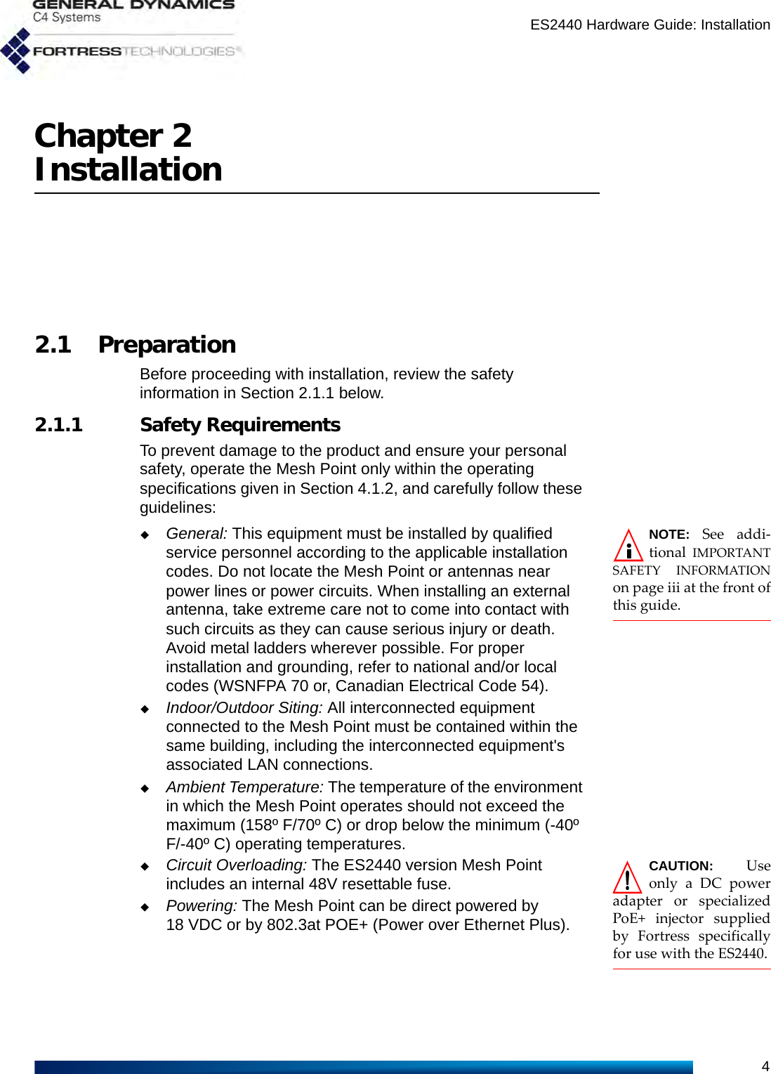
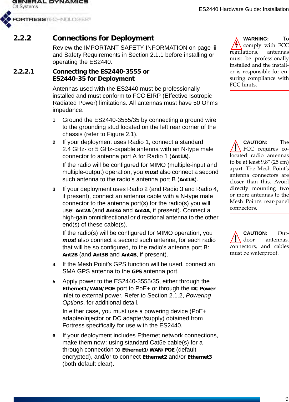
![ES2440 Hardware GuidevIn addition, the FCC recommends that all operators and installers register with the WISPA database used by government agencies to quickly find devices that may be causing interference and notify their owners/operators to shut them down. This registration is not required, but Fortress strongly recommends that all systems be registered, as described in this excerpt of KDB 44399:A voluntary WISPA sponsored database has been developed that allows operators and installers to register the location information of the UNII devices operating outdoors in the 5470 – 5725 MHz band within 35 km of any TDWR location (see http://www.spectrumbridge.com/udia/home.aspx). This database may be used by government agencies in order to expedite resolution of any interference to TDWRs. KDB 443999 further specifies that the requirements of KDB 594280 must also be met. KDB 594280 is published in full on the FCC web site: https://apps.fcc.gov/oetcf/kdb/forms/FTSSearchResultPage.cfm?switch=P&id=39498. This device meets KDB 594280 by not allowing any configuration options to be made such that the device could be taken out of compliance. There is no ability for the user to change country codes or to select power levels that would take the device out of compliance.For customers such as the U.S. military or others willing to produce evidence that particular devices will be used only outside of the United States, a special license can be obtained from Fortress that will allow those devices the option of selecting a different, non-U.S. country code. Fortress creates such licenses only for those customers who offer proof of non-U.S. device usage, and licenses are specific to particular devices and are not transferrable. Devices having such a license should NOT be considered to be compliant with FCC regulatory requirements. Please contact Fortress with questions about these special licences.Only software that has been signed by Fortress using the Fortress private key can be loaded onto a Fortress device, thus insuring that no software other than that which is controlled and signed by Fortress can by loaded onto the device.FCC EMISSIONS COMPLIANCE AND INDUSTRY CANADA STATEMENTSTHIS EQUIPMENT HAS BEEN TESTED AND FOUND TO COMPLY WITH THE LIMITS FOR A CLASS B DIGITAL DEVICE, PURSUANT TOPART 15 OF THE FCC RULES. THESE LIMITS ARE DESIGNED TO PROVIDE REASONABLE PROTECTION AGAINST HARMFUL INTERFERENCE IN A RESIDENTIAL INSTALLATION. THIS EQUIPMENT GENERATES, USES, AND CAN RADIATE RADIO FREQUENCY ENERGY AND, IF NOT INSTALLED AND USED IN ACCORDANCE WITH THE INSTRUCTIONS, MAY CAUSE HARMFUL INTERFERENCE TO RADIO COMMUNICATIONS. HOWEVER, THERE IS NO GUARANTEE THAT INTERFERENCE WILL NOT OCCUR IN A PARTICULAR INSTALLATION. IF THIS EQUIPMENT DOES CAUSE OK AERO. CTR TDWR #2 W 097 37 43 N 35 23 34 5620 MHz 1293 97 OK TULSA W 095 49 34 N 36 04 14 5605 MHz 712 113 OK OKLAHOMA CITY W 097 30 36 N 35 16 34 5603 MHz 1195 64 PA HANOVER W 080 29 10 N 40 30 05 5615 MHz 1266 113 PR SAN JUAN W 066 10 46 N 18 28 26 5610 MHz 59 113 TN NASHVILLE W 086 39 42 N 35 58 47 5605 MHz 722 97 TX HOUSTON INTERCONTL W 095 34 01 N 30 03 54 5605 MHz 154 97 TDWR Location Information TERRAIN ELEVATION (MSL) [ft] ANTENNA HEIGHT ABOVE TERRAIN [ft] STATE CITY LONGITUDE LATITUDE FREQUENCY](https://usermanual.wiki/Fortress-Technologies/ES2440X.User-Manual/User-Guide-1815838-Page-6.png)