Fortress Technologies ES2440X Dual Radio Access Point/Bridge User Manual
Fortress Technologies, Inc. Dual Radio Access Point/Bridge
Contents
- 1. Marketing Literuature
- 2. User Manual
- 3. Marketing Literature
User Manual

ES2440
High-Capacity
Infrastructure
Mesh Point
Hardware Guide
www.gdfortress.com
© 2012 Fortress Technologies, Inc.

ES2440 Hardware Guide
i
009-00045-00r4
Fortress ES2440 High-Capacity Infrastructure Mesh Point [rev.4a]
Copyright © 2012 Fortress Technologies, Inc. All rights reserved.
This document contains proprietary information protected by copyright. No part of this
document may be reproduced or transmitted in any form or by any means, electronic or
mechanical, without written permission of Fortress Technologies, 2 Technology Park Drive,
Westford, MA 01886-3140, except as specified in the Product Warranty and License
Terms.
FORTRESS TECHNOLOGIES MAKES NO WARRANTY OF ANY KIND WITH REGARD
TO THIS MATERIAL, INCLUDING BUT NOT LIMITED TO THE IMPLIED WARRANTIES
OF MERCHANTABILITY AND FITNESS FOR A PARTICULAR PURPOSE. FORTRESS
TECHNOLOGIES SHALL NOT BE LIABLE FOR ERRORS CONTAINED HEREIN OR
FOR INCIDENTAL OR CONSEQUENTIAL DAMAGES IN CONNECTION WITH THE
FURNISHING, PERFORMANCE OR USE OF THIS MATERIAL. THE INFORMATION IN
THIS DOCUMENT IS SUBJECT TO CHANGE WITHOUT NOTICE.
The General Dynamics C4 Systems | Fortress Technologies, Fortress Technologies and
AirFortress logos and AirFortress and are registered trademarks. Multi-Factor
Authentication, Unified Security Model, Wireless Link Layer Security and Three Factor
Authentication (TFA) are trademarks of Fortress Technologies, Inc. The technology behind
Wireless Link Layer Security™ enjoys U.S. and international patent protection under patent
number 5,757,924.
All trademarks mentioned in this document are the property of their respective owners.
LIMITED WARRANTY
Hardware
Fortress warrants the Hardware will be free of defects in material and workmanship under
normal use. Fortress further warrants that the Hardware will conform to Specifications in
effect on the date of shipment of the product, from Fortress location.
Software
The Limited Warranty as described in the Fortress End User License Agreement (EULA)
sets forth Fortress’ warranty obligations with respect to Software. This End User License
Agreement is included with the product or a copy may be obtained at the following URL:
http://www.gdfortress.com/Support/general-support.html
This limited warranty extends only to the original purchaser of the Product.
DURATION OF WARRANTY
Hardware and Software is warranted for a period of one (1) year commencing from the ship
date to Purchaser [and in the case of resale by a Fortress Solution Provider, commencing
not more than (90) days after original shipment by Fortress]. The date of shipment is
established per the shipping document (packing list) for the Product that is shipped.
REMEDIES
Purchaser’s sole and exclusive remedy (within the warranty period) and the entire liability
of Fortress and its suppliers under this limited warranty will be, after return to a Fortress
repair facility, the repair and return of Product to Purchaser. At Fortress’ option if it is not
able to repair the product, we will replace it with a comparable product that is new or
refurbished. Purchaser shall pay expenses for return of such Products to Fortress. Fortress
shall pay expenses for shipment of returned Products to Purchaser.
WARRANTY EXCLUSIONS
The above Hardware and Software (EULA) limited warranty do not apply if the Hardware
Product or Software or any other equipment upon which the Software is authorized by
Fortress or its suppliers or licensors to be used (a) has been damaged through abuse or
negligence or by accident, (b) has been altered except by an authorized Fortress
representative, (c) has been subjected to abnormal physical or electrical stress (i.e.,
lightning strike) or abnormal environmental conditions, (d) has been lost or damaged in

ES2440 Hardware Guide
ii
transit, or (e) has not been installed, operated, repaired or maintained in accordance with
instructions provided by Fortress.
Purchaser is responsible for all freight expenses incurred as a result of returning Products
that are determined by Fortress to be (1) free from defect or (2) defective as a result of one
of the circumstances listed in (a) through (e) above.
Such Products shall be shipped back to Purchaser, and Purchaser shall be responsible for
associated freight charges. If Products are returned to Purchaser, title to the Products and
risk of loss shall pass to Purchaser at the time Fortress delivers Products to the carrier for
shipment.
Limited Warranty shall apply only to those Products that are branded by Fortress with a
Fortress trademark ("Fortress Branded"). Fortress does not warrant any third party
Products even if included with other Fortress Branded Products. Furthermore, Fortress
provides all such third party Products AS IS. However, the original manufacturers or
suppliers may provide their own warranties as specified in the documentation
accompanying such third party Products.
LIMITED MAINTENANCE & SUPPORT
Fortress provides “Limited Maintenance & Support” on its Products during the Limited
Warranty period. Limited Hardware Maintenance & Support consists of (a) repair or
replacement of defective components/products and (b) remote technical support. Limited
Software Maintenance & Support consists of (a) bug fixes, (b) maintenance releases, and
(c) remote technical support.
Limited Maintenance & Support will be provided based on the Urgency & Escalation
process in affect at the time of the trouble report.
Issues with products are reported by calling Fortress Technical Support at (978) 923-6400.
Note: Please be prepared to provide the product serial number(s), version number(s), and
name of the company the product was purchased from (if other than Fortress) to the
Fortress Technical Support Engineer; this will assist in determining maintenance & support
status.
Technical Support will work to resolve the issue over the phone. If a product needs to be
returned to Fortress for repair or replacement; a Returned Materials Authorization (RMA)
number will be issued for the return. Note: Fortress Technical Support will e-mail the RMA
information which will provide the ship to address, to the person requesting the RMA.
Purchaser ships the product(s) to the address provided for repairs or replacement. Notes:
(1) Purchaser pays for shipping to Fortress Technologies service location. (2) Fortress pays
for return of repaired or replacement product(s) back to Purchaser location. (3) Fortress
evaluates the product and either repairs or replaces it free of charge, other than for
Warranty Exclusions.
Services and support provided to diagnose a reported issue with a Fortress Product, which
is then determined not to be the root cause of the issue, may at Fortress’ option be billed at
the standard time and material rates.
Fortress will make all reasonable efforts to repair or replace any returned Product(s) within
10 business days of receipt.
Fortress Technologies Inc. reserves the right to use refurbished parts to complete repairs.
Maintenance & Support Exclusions
Products that are determined by Fortress to be (1) free from defect or (2) defective as a
result of one of the circumstances listed in (a) through (e) in Warranty Exclusions above;
are not covered under the Service & Support Program. Such repairs with the consent of the
Purchaser would be performed on a Time & Materials basis.
WARRANTY DISCLAIMERS
THE WARRANTIES HEREIN ARE SOLE AND EXCLUSIVE, AND NO OTHER
WARRANTY, WHETHER WRITTEN OR ORAL, IS EXPRESSED OR IMPLIED. TO THE
EXTENT PERMITTED BY LAW, FORTRESS SPECIFICALLY DISCLAIMS THE IMPLIED
WARRANTIES OF MERCHANTABILITY, FITNESS FOR A PARTICULAR PURPOSE,
TITLE AND NONINFRINGEMENT.
ES2440 Hardware Guide
iii
IMPORTANT SAFETY INFORMATION
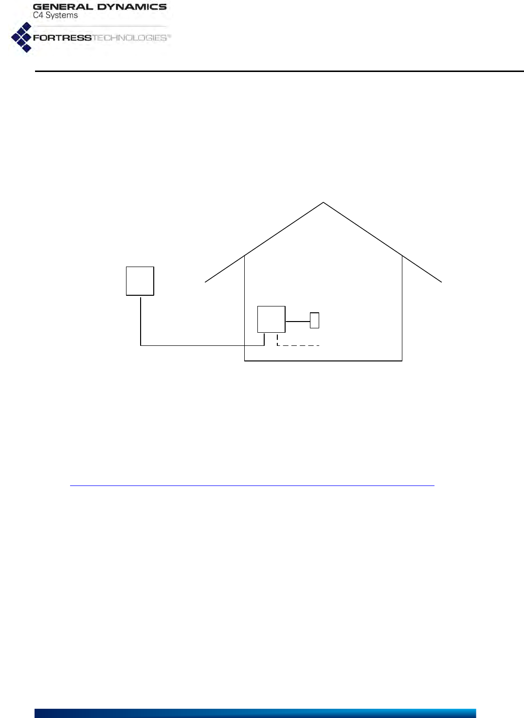
The ES2440 is an outdoor device. It should be powered by a mid-span PoE (Power over Ethernet)
injector obtained from Fortress Technologies over a weatherized Ethernet cable OR by a DC
power adapter/supply obtained from Fortress Technologies over a weatherized DC power cable.
Either power source, mid-span PoE injector or DC power supply, and the power cord and AC
supply it plugs into should remain indoors, protected from the weather. The connection between
the ES2440 and its indoor power source/connectors must be made using a weatherized cable
(Ethernet or DC power). In this way, power can be safely provided to the outdoor ES2440 while the
power source/connectors remain protected indoors, as shown:
IMPORTANT FCC INFORMATION
The Federal Communications Commission has released Office of Engineering and Technology
Laboratory Division Knowledge Database (KDB) 44399, which refines the definition of Dynamic
Frequency Selection (DFS) support. Since this device has the ability to use frequencies covered
by DFS, KDB 443999 must be followed. It is published in full on the FCC web site:
https://apps.fcc.gov/oetcf/kdb/forms/FTSSearchResultPage.cfm?switch=P&id=41732
In order to support FCC KDB 443999, Fortress has limited the use of certain frequencies within
the 5400–5725 MHz range. Specifically, the frequencies defined by the FCC as being of primary
interest are those in the 5600–5650 MHz range, which correspond to 802.11a channels 120, 124,
and 128. In order to comply with the KDB 443999, these channels have been removed from use,
or notched. Notched channels are unavailable for use on this device.
KDB 44399 provides additional restrictions on the use of channels within 30 MHz of notched
channels when the device is within 35 km of a Terminal Doppler Weather Radar (TDWR)
installation. Affected channels 116, 132, and 136 serve as a guard of 30 MHz around the critical
notched frequencies. Guard frequencies are unavailable for use on this device by default. The
FCC allows these channels to be used, however, as long as the device is not within 35 km of a
TDWR installation, as described in this excerpt of KDB 443999:
Any installation of either a master or a client device within 35 km of a TDWR location shall
be separated by at least 30 MHz (center-to-center) from the TDWR operating frequency.
In some instances it is possible that a device may be within 35 km of multiple TDWRs. In
this case the device must ensure that it avoids operation within 30 MHz for each of the
ES2440
weatherized Ethernet
-or-DC power cable
PoE mid-span injector
-or-DC power supply
Ethernet
(if used)
AC wall
outlet

ES2440 Hardware Guide
iv
TDWRs. This requirement applies even if the master is outside the 35 km radius but
communicates with outdoor clients which may be within the 35 km radius of the TDWRs.
The requirement for ensuring 30 MHz frequency separation is based on the best
information available to date. If interference is not eliminated, a distance limitation based
on line-of-sight from TDWR will need to be used.
Please refer to the original KDB 443999 as posted on the FCC web site for the complete text.
In order to enable channels 116, 132, and/or 136, please contact Fortress to obtain a special
license. This license will be issued after it is confirmed that the installation is not within 30 MHz and
35 km of registered TDWR sites. The following table (provided by the FCC in KDB 443999
published on 10/14/2010) describes the locations of TDWR sites, as well as the frequencies at
which these sites operate:
TDWR Location Information TERRAIN
ELEVATION
(MSL) [ft]
ANTENNA
HEIGHT ABOVE
TERRAIN [ft]
STATE CITY LONGITUDE LATITUDE FREQUENCY
AZ PHOENIX W 112 09 46 N 33 25 14 5610 MHz 1024 64
CO DENVER W 104 31 35 N 39 43 39 5615 MHz 5643 64
FL FT LAUDERDALE W 080 20 39 N 26 08 36 5645 MHz 7 113
FL MIAMI W 080 29 28 N 25 45 27 5605 MHz 10 113
FL ORLANDO W 081 19 33 N 28 20 37 5640 MHz 72 97
FL TAMPA W 082 31 04 N 27 51 35 5620 MHz 14 80
FL WEST PALM BEACH W 080 16 23 N 26 41 17 5615 MHz 20 113
GA ATLANTA W 084 15 44 N 33 38 48 5615 MHz 962 113
IL MCCOOK W 087 51 31 N 41 47 50 5615 MHz 646 97
IL CRESTWOOD W 087 43 47 N 41 39 05 5645 MHz 663 113
IN INDIANAPOLIS W 086 26 08 N 39 38 14 5605 MHz 751 97
KS WICHITA W 097 26 13 N 37 30 26 5603 MHz 1270 80
KY COVINGTON
CINCINNATI W 084 34 48 N 38 53 53 5610 MHz 942 97
KY LOUISVILLE W 085 36 38 N 38 02 45 5646 MHz 617 113
LA NEW ORLEANS W 090 24 11 N 30 01 18 5645 MHz 2 97
MA BOSTON W 070 56 01 N 42 09 30 5610 MHz 151 113
MD BRANDYWINE W 076 50 42 N 38 41 43 5635 MHz 233 113
MD BENFIELD W 076 37 48 N 39 05 23 5645 MHz 184 113
MD CLINTON W 076 57 43 N 38 45 32 5615 MHz 249 97
MI DETROIT W 083 30 54 N 42 06 40 5615 MHz 656 113
MN MINNEAPOLIS W 092 55 58 N 44 52 17 5610 MHz 1040 80
MO KANSAS CITY W 094 44 31 N 39 29 55 5605 MHz 1040 64
MO SAINT LOUIS W 090 29 21 N 38 48 20 5610 MHz 551 97
MS DESOTO COUNTY W 089 59 33 N 34 53 45 5610 MHz 371 113
NC CHARLOTTE W 080 53 06 N 35 20 14 5608 MHz 757 113
NC RALEIGH DURHAM W 078 41 50 N 36 00 07 5647 MHz 400 113
NJ WOODBRIDGE W 074 16 13 N 40 35 37 5620 MHz 19 113
NJ PENNSAUKEN W 075 04 12 N 39 56 57 5610 MHz 39 113
NV LAS VEGAS W 115 00 26 N 36 08 37 5645 MHz 1995 64
NY FLOYD BENNETT
FIELD W 073 52 49 N 40 35 20 5647 MHz 8 97
OH DAYTON W 084 07 23 N 40 01 19 5640 MHz 922 97
OH CLEVELAND W 082 00 28 N 41 17 23 5645 MHz 817 113
OH COLUMBUS W 082 42 55 N 40 00 20 5605 MHz 1037 113
OK AERO. CTR TDWR #1 W 097 37 31 N 35 24 19 5610 MHz 1285 80

ES2440 Hardware Guide
v
In addition, the FCC recommends that all operators and installers register with the WISPA
database used by government agencies to quickly find devices that may be causing interference
and notify their owners/operators to shut them down. This registration is not required, but Fortress
strongly recommends that all systems be registered, as described in this excerpt of KDB 44399:
A voluntary WISPA sponsored database has been developed that allows operators and
installers to register the location information of the UNII devices operating outdoors in the
5470 – 5725 MHz band within 35 km of any TDWR location (see
http://www.spectrumbridge.com/udia/home.aspx). This database may be used by
government agencies in order to expedite resolution of any interference to TDWRs.
KDB 443999 further specifies that the requirements of KDB 594280 must also be met.
KDB 594280 is published in full on the FCC web site:
https://apps.fcc.gov/oetcf/kdb/forms/FTSSearchResultPage.cfm?switch=P&id=39498.
This device meets KDB 594280 by not allowing any configuration options to be made such that the
device could be taken out of compliance. There is no ability for the user to change country codes
or to select power levels that would take the device out of compliance.
For customers such as the U.S. military or others willing to produce evidence that particular
devices will be used only outside of the United States, a special license can be obtained from
Fortress that will allow those devices the option of selecting a different, non-U.S. country code.
Fortress creates such licenses only for those customers who offer proof of non-U.S. device usage,
and licenses are specific to particular devices and are not transferrable. Devices having such a
license should NOT be considered to be compliant with FCC regulatory requirements. Please
contact Fortress with questions about these special licences.
Only software that has been signed by Fortress using the Fortress private key can be loaded onto
a Fortress device, thus insuring that no software other than that which is controlled and signed by
Fortress can by loaded onto the device.
FCC EMISSIONS COMPLIANCE
AND INDUSTRY CANADA STATEMENTS
THIS EQUIPMENT HAS BEEN TESTED AND FOUND TO COMPLY
WITH THE LIMITS FOR A CLASS B DIGITAL DEVICE, PURSUANT TO
PART 15 OF THE FCC RULES. THESE LIMITS ARE DESIGNED TO
PROVIDE REASONABLE PROTECTION AGAINST HARMFUL
INTERFERENCE IN A RESIDENTIAL INSTALLATION. THIS
EQUIPMENT GENERATES, USES, AND CAN RADIATE RADIO
FREQUENCY ENERGY AND, IF NOT INSTALLED AND USED IN
ACCORDANCE WITH THE INSTRUCTIONS, MAY CAUSE HARMFUL
INTERFERENCE TO RADIO COMMUNICATIONS. HOWEVER, THERE
IS NO GUARANTEE THAT INTERFERENCE WILL NOT OCCUR IN A
PARTICULAR INSTALLATION. IF THIS EQUIPMENT DOES CAUSE
OK AERO. CTR TDWR #2 W 097 37 43 N 35 23 34 5620 MHz 1293 97
OK TULSA W 095 49 34 N 36 04 14 5605 MHz 712 113
OK OKLAHOMA CITY W 097 30 36 N 35 16 34 5603 MHz 1195 64
PA HANOVER W 080 29 10 N 40 30 05 5615 MHz 1266 113
PR SAN JUAN W 066 10 46 N 18 28 26 5610 MHz 59 113
TN NASHVILLE W 086 39 42 N 35 58 47 5605 MHz 722 97
TX HOUSTON
INTERCONTL W 095 34 01 N 30 03 54 5605 MHz 154 97
TDWR Location Information TERRAIN
ELEVATION
(MSL) [ft]
ANTENNA
HEIGHT ABOVE
TERRAIN [ft]
STATE CITY LONGITUDE LATITUDE FREQUENCY

ES2440 Hardware Guide
vi
HARMFUL INTERFERENCE TO RADIO OR TELEVISION RECEPTION,
WHICH CAN BE DETERMINED BY TURNING THE EQUIPMENT OFF
AND ON, THE USER IS ENCOURAGED TO TRY TO CORRECT THE
INTERFERENCE BY ONE OR MORE OF THE FOLLOWING
MEASURES:
• REORIENT OR RELOCATE THE RECEIVING ANTENNA.
• INCREASE THE SEPARATION BETWEEN THE EQUIPMENT AND
THE RECEIVER.
• CONNECT THE EQUIPMENT INTO AN OUTLET ON A CIRCUIT
DIFFERENT FROM THAT TO WHICH THE RECIEVER IS
CONNECTED.
• CONSULT THE DEALER OR AN EXPERIENCED RADIO/TV
TECHNICIAN FOR HELP.
YOU MAY ALSO FIND HELPFUL THE FOLLOWING BOOKLET,
PREPARED BY THE FCC: “HOW TO IDENTIFY AND RESOLVE
RADIOTV INTERFERENCE PROBLEMS.” THIS BOOKLET IS
AVAILABLE FROM THE U.S. GOVERNMENT PRINTING OFFICE,
WASHINGTON, D.C. 20402
CHANGES AND MODIFICATIONS NOT EXPRESSLY APPROVED BY
THE MANUFACTURER OR REGISTRANT OF THIS EQUIPMENT CAN
VOID YOUR AUTHORITY TO OPERATE THIS EQUIPMENT UNDER
FEDERAL COMMUNICATIONS COMMISSION RULES. IN ORDER TO
MAINTAIN COMPLIANCE WITH FCC REGULATIONS, SHIELDED
CABLES MUST BE USED WITH THIS EQUIPMENT. OPERATION WITH
NON-APPROVED EQUIPMENT OR UNSHIELDED CABLES IS LIKELY
TO RESULT IN INTERFERENCE TO RADIO AND TELEVISION
RECEPTION.
IN ADDITION, USERS SHOULD ALSO BE CAUTIONED TO TAKE NOTE
THAT HIGH POWER RADARS ARE ALLOCATED AS PRIMARY USERS
(MEANING THEY HAVE PRIORITY) OF 5250-5350 MHZ AND 5650-5850
MHZ AND THESE RADARS COULD CAUSE INTERFERENCE AND/OR
DAMAGE TO LE-LAN DEVICES.
ICES-003 STATEMENT:
THIS CLASS B DIGITAL APPARATUS COMPLIES WITH CANADIAN
ICES-003.
CET APPAREIL NUMÉRIQUE DE LA CLASSE B EST CONFORME À LA
NORME NMB-003 DU CANADA.
OPERATION IS SUBJECT TO THE FOLLOWING TWO CONDITIONS:
(1) THIS DEVICE MAY NOT CAUSE INTERFERENCE, AND (2) THIS
DEVICE MUST ACCEPT ANY INTERFERENCE, INCLUDING
INTERFERENCE THAT MAY CAUSE UNDESIRED OPERATION OF
THE DEVICE.
TO REDUCE POTENTIAL RADIO INTERFERENCE TO OTHER USERS,
THE ANTENNA TYPE AND ITS GAIN SHOULD BE SO CHOSEN THAT
THE EQUIVALENT ISOTROPICALLY RADIATED POWER (E.I.R.P.) IS
NOT MORE THAN THAT PERMITTED FOR SUCCESSFUL
COMMUNICATION.

ES2440 Hardware Guide
vii
CAUTION: 4.4 GHZ RADIOS ARE OPTIONAL EQUIPMENT IN
THE ES2440. THE 4.400 GHZ–4.780 GHZ FREQUENCY RANGE
IS REGULATED BY THE UNITED STATES NATIONAL TELECOM-
MUNICATIONS AND INFORMATION ADMINISTRATION AND
ALLOCATED EXCLUSIVELY FOR GOVERNMENT USE. USE OF
4.4 GHZ RADIOS OUTSIDE OF U.S. GOVERNMENT APPLICATIONS
AND AUTHORITY IS STRICTLY FORBIDDEN.

ES2440 Hardware Guide: Table of Contents
viii
Table of Contents
1
Overview 1
This Document . . . . . . . . . . . . . . . . . . . . . . . . . . . . . . . . . . . . . . . . .1
Related Documents . . . . . . . . . . . . . . . . . . . . . . . . . . . . . . . . . . . . . . . . . . .1
The ES2440 . . . . . . . . . . . . . . . . . . . . . . . . . . . . . . . . . . . . . . . . . . .2
Hardware Models . . . . . . . . . . . . . . . . . . . . . . . . . . . . . . . . . . . . . . . . . . . . .2
Shipped and Optional Parts . . . . . . . . . . . . . . . . . . . . . . . . . . . . . . . . . . . . .3
2
Installation 4
Preparation . . . . . . . . . . . . . . . . . . . . . . . . . . . . . . . . . . . . . . . . . . . .4
Safety Requirements . . . . . . . . . . . . . . . . . . . . . . . . . . . . . . . . . . . . . . . . . .4
Powering Options . . . . . . . . . . . . . . . . . . . . . . . . . . . . . . . . . . . . . . . . . . . . .5
Port and Grounding Stud Locations . . . . . . . . . . . . . . . . . . . . . . . . . . . . . . .6
Front-Panel Connectors . . . . . . . . . . . . . . . . . . . . . . . . . . . . . . . . . . . . . . . . . . . . . . . . .6
Grounding Stud . . . . . . . . . . . . . . . . . . . . . . . . . . . . . . . . . . . . . . . . . . . . . . . . . . . . . . .7
Rear Panel Connectors . . . . . . . . . . . . . . . . . . . . . . . . . . . . . . . . . . . . . . . . . . . . . . . . .7
Connecting the ES2440 . . . . . . . . . . . . . . . . . . . . . . . . . . . . . . . . . .8
Connections for Preconfiguration . . . . . . . . . . . . . . . . . . . . . . . . . . . . . . . . .8
Connections for Deployment . . . . . . . . . . . . . . . . . . . . . . . . . . . . . . . . . . . .9
Connecting the ES2440-3555 or ES2440-35 for Deployment . . . . . . . . . . . . . . . . . . . .9
Connecting the ES2440-3444 or ES2440-34 for Deployment . . . . . . . . . . . . . . . . . . . 10
Connecting the ES2440-0 for Deployment . . . . . . . . . . . . . . . . . . . . . . . . . . . . . . . . . . 10
Disconnection . . . . . . . . . . . . . . . . . . . . . . . . . . . . . . . . . . . . . . . . . . . . . . . 10
Mast Mounting the ES2440 . . . . . . . . . . . . . . . . . . . . . . . . . . . . . . 11

ES2440 Hardware Guide: Table of Contents
ix
3
LEDs and Button Operation 12
Front-Panel LED Indicators . . . . . . . . . . . . . . . . . . . . . . . . . . . . . . 12
Recessed Button Operation . . . . . . . . . . . . . . . . . . . . . . . . . . . . . . 13
4
Specifications 14
Hardware Specifications . . . . . . . . . . . . . . . . . . . . . . . . . . . . . . . . . 14
Physical Specifications . . . . . . . . . . . . . . . . . . . . . . . . . . . . . . . . . . . . . . . . 14
Environmental Specifications . . . . . . . . . . . . . . . . . . . . . . . . . . . . . . . . . . . 15
Compliance and Standards . . . . . . . . . . . . . . . . . . . . . . . . . . . . . . . . . . . . 15
RJ45-to-DB9 Serial Port Adapter . . . . . . . . . . . . . . . . . . . . . . . . . . 15
2-Pin DC Input Connector . . . . . . . . . . . . . . . . . . . . . . . . . . . . . . . . 16
Index I
ES2440 Hardware Guide: Overview
1
Chapter 1
Overview
1.1 This Document
WARNING: can
cause physical in-
jury or death and/or se-
verely damage your
equipment.
This user guide covers preparing and installing the Fortress
ES2440 High-Capacity Infrastructure Mesh Point hardware. It
also describes the LED indicators and recessed button
operation and provides specifications. Other Fortress hardware
devices are covered in separate hardware guides, one for each
Mesh Point (or Network Encryptor) model.
Fortress Mesh Point user guidance is intended for professional
system and network administrators and assumes that its users
have a level of technical expertise consistent with these roles.
CAUTION: can cor-
rupt your net-
work, your data or an
intended result.
Side notes throughout this document are intended to alert you
to particular kinds of information, as visually indicated by their
icons. Examples appear to the right of this section, in
descending order of urgency.
NOTE: may assist
you in executing
the task, e.g. a conve-
nient software feature or
notice of something to
keep in mind.
1.1.1 Related Documents
Each Fortress hardware series runs the same Fortress
software, and differences between ES and FC series software
are minor. Fortress software user guidance covers all current
Fortress hardware platforms.
Fortress Mesh Point software guides include:
Mesh Point and Network Encryptor Software GUI Guide
Mesh Point and Network Encryptor Software CLI Guide
Mesh Point and Network Encryptor Software Auto Config-
uration Guide
In addition to this guide, the Fortress hardware guides include:
ES210 Tactical Mesh Point Hardware Guide
ES440 Infrastructure Mesh Point Hardware Guide
ES520 Deployable Mesh Point Hardware Guide
ES820 Vehicle Mesh Point Hardware Guide
FC-X Inline Network Encryptor Hardware Guide
ES2440 Hardware Guide: Overview
2
1.2 The ES2440
The ES2440 High-Capacity Infrastructure Mesh Point is a
full-featured Fortress network device, providing strong data
encryption and Multi-factor Authentication™, including native
RADIUS authentication, to users and devices on the network it
secures.
Two ES2440 models are each equipped with four radios:
NOTE: Although
optional 4.4 GHz
radios are covered
throughout this guide,
as of the version 5.4.1 re-
lease, they were not yet
supported in Mesh
Point software. Consult
your Fortress represen-
tative about future
4.4 GHz radio support
on the ES2440.
Radio 1 is a 400 mW (milliwatt, peak power) dual-band
802.11a/b/g/n radio that can be configured to use either the
802.11b/g band or the 802.11a band, with an option for
802.11n capability in either band. Radio 1 supports Multiple-
Input Multiple-Output (MIMO) operation.
Standard equipment Radio 2, Radio 3 and Radio 4 are
631 mW (peak power) radios fixed on the 802.11a band,
also with an option for 802.11n capability and MIMO
support. The ES2440 can be optionally equipped with three
800mW (peak power) 802.11a/n 4.4 GHz radios in place of
the standard equipment Radios 2, 3, and 4. The 4.4 GHz
radios do not support MIMO.
Any of the ES2440’s radios can function as a wireless
access point (AP), providing secure WLAN connectivity to
wireless devices within range and as a wireless bridge or
node in a mesh network.
A third ES2440 model without radios—the High-Capacity
Infrastructure Mesh Point for Inline Encryption—is intended
exclusively for wired Ethernet operation.
All ES2440 models are equipped with an internal global
positioning system (GPS) receiver.
1.2.1 Hardware Models CAUTION: Use of
4.4 GHz radios
outside of U.S. Govern-
ment applications and
authority is strictly for-
bidden.
You can identify by the full model number of the ES2440
whether it is equipped with radios and, if so, how many internal
radio are installed and whether they are standard dual band or
5 GHz 802.11a radios or 4.4 GHz radios:
ES2440-3555 - four radios:
one dual band 802.11a/b/g/n MIMO-capable radio
three 802.11a/n 5 GHz MIMO-capable radios
ES2440-3444 - four radios:
one dual band 802.11a/b/g/n MIMO-capable radio
three 4.4 GHz radios
ES2440-35 - two radios:
one dual band 802.11a/b/g/n MIMO-capable radio
one 802.11a/n 5 GHz MIMO-capable radio
ES2440-34 - two radios:
one dual band 802.11a/b/g/n MIMO-capable radio
one 4.4 GHz radio
ES2440-0 - no radios
ES2440 Hardware Guide: Overview
3
The 4.400 GHz–4.780 GHz frequency range is regulated by
the NTIA (National Telecommunications and Information
Administration), the parent agency of the FCC (Federal
Communications Commission). FCC labeling applied to the
ES2440-3444 chassis therefore provides an FCC ID for only
the 802.11a Radio 1.
Each radio-equipped model is furnished with the appropriate
rear-panel antenna port configuration for the number and type
of radios installed.
NOTE: Radio-relat-
ed content in this
guide, including regula-
tory information and
precautions, does not
apply to the ES2440-0.
Rear-panel radio antenna ports and front-panel radio LED
indicators are absent from the ES2440-0, and FCC markings
appropriate for network devices incapable of wireless operation
are applied to the chassis.
ES2440 chassis are otherwise identical.
1.2.2 Shipped and Optional Parts
All ES2440 shipments include (Fortress part numbers in
parentheses):
one ES2440 Mesh Point
one DB9-to-RJ45 serial adapter (part # 139-00002-01)
three weatherized Ethernet shell connectors
(part # 200-00229-01)
one software CD, including:
ES2440 Mesh Point software package
Fortress and standard SNMP MIBs
RADIUS dictionary file with Fortress Vendor-Specific
Attributes for administrative authentication
ES2440 Mesh Point user guides and latest release
notes
These additional items are included in shipments of radio-
equipped ES2440s:
one 18 VDC power adapter/supply (part # 270-00144-01)
one AC power cord (part # 620-00016-01)
one mast mounting kit (part # 381-00004-01)
This additional item is included in shipments of the ES2440-0:
one DC power cable/connector assembly
(part # 620-00070-01)
Optionally Available from Fortress
60W
passive POE+ adapter/injector, gigabit compatible
(part # 270-00139-01)
replacement 18 VDC power adapter/supply
(part # 270-00144-01)
AC power cord for use with either of the above
(part # 620-00016-01)
ES2440 Hardware Guide: Installation
4
Chapter 2
Installation
2.1 Preparation
Before proceeding with installation, review the safety
information in Section 2.1.1 below.
2.1.1 Safety Requirements
To prevent damage to the product and ensure your personal
safety, operate the Mesh Point only within the operating
specifications given in Section 4.1.2, and carefully follow these
guidelines:
NOTE: See addi-
tional IMPORTANT
SAFETY INFORMATION
on page iii at the front of
this guide.
General: This equipment must be installed by qualified
service personnel according to the applicable installation
codes. Do not locate the Mesh Point or antennas near
power lines or power circuits. When installing an external
antenna, take extreme care not to come into contact with
such circuits as they can cause serious injury or death.
Avoid metal ladders wherever possible. For proper
installation and grounding, refer to national and/or local
codes (WSNFPA 70 or, Canadian Electrical Code 54).
Indoor/Outdoor Siting: All interconnected equipment
connected to the Mesh Point must be contained within the
same building, including the interconnected equipment's
associated LAN connections.
Ambient Temperature: The temperature of the environment
in which the Mesh Point operates should not exceed the
maximum (158º F/70º C) or drop below the minimum (-40º
F/-40º C) operating temperatures.
CAUTION: Use
only a DC power
adapter or specialized
PoE+ injector supplied
by Fortress specifically
for use with the ES2440.
Circuit Overloading: The ES2440 version Mesh Point
includes an internal 48V resettable fuse.
Powering: The Mesh Point can be direct powered by
18 VDC or by 802.3at POE+ (Power over Ethernet Plus).

ES2440 Hardware Guide: Installation
5
WARNING: If the
Mesh Point con-
nects to outside-mount-
ed antennas, failure to
provide a low resistive
earth ground can result
in migration of voltage
from lightning or line
surges onto the premis-
es wiring, which can
cause electric shock
and/or fire within the
building or structure.
Grounding: Ground the ES2440 by connecting a ground
wire to the grounding stud located on the left rear corner of
the chassis (
refer to Figures 2.1 and 2.2, below
).
Radio Frequency: The Mesh Point’s internal radios conform
to the FCC’s safety standard for human exposure to RF
electromagnetic energy, provided that you follow these
guidelines:
Do not touch or move the antennas while the unit is
transmitting or receiving.
To safeguard Mesh Point transmitting circuitry, relocate
the Mesh Point and its antennas only when the Mesh
Point is powered off.
When the Mesh Point is transmitting, do not hold it so
that the antenna is very close to or touching any
exposed parts of the body, especially the face or eyes.
Antennas must be installed to provide a separation of at
least 25 cm (9.8") from all persons and any co-located
antenna or transmitter.
Regarding use in specific environments: · Do not
operate near unshielded blasting caps or in an
explosive environment. · Limit use in a hazardous
location to the constraints imposed by the location’s
safety director. · Abide by the rules of the Federal
Aviation Administration for the use of wireless devices
on airplanes. · Restrict the use of wireless devices in
hospitals to the limits set forth by each hospital.
2.1.2 Powering Options
The ES2440 can be powered with:
the 60W
passive 802.3at PoE+ (Power over Ethernet Plus)
gigabit compatible adapter/injector via the Ethernet1 port
the 18 VDC (volts direct current) power adapter/supply via
the DC Power inlet
external DC power over the DC power cable/connector
assembly, via the DC Power inlet
In any case, the power adapter (PoE+ or DC) or cable/
connector assembly must be one obtained from Fortress
specifically for use with the ES2440, or damage to the ES2440
could result.
Whether the mid-span PoE+ injector or a DC power supply is
used to power the ES2440, the powering device, its power
cord, and the supply it plugs into must remain indoors,
protected from the weather. The connection between the
ES2440 and its indoor power source/connectors must be made
using a weatherized Ethernet or DC power cable.
The external DC power option is not intended to be a
redundant back-up supply to PoE (or vice versa). The ES2440
ES2440 Hardware Guide: Installation
6
will automatically disconnect PoE if external DC power is
applied and will only reconnect PoE when DC power is
removed. When either PoE or external DC are removed, the
ES2440 will reboot.
Follow one of these procedures to power the ES2440:
with the POE+ adapter
Plug the PoE+ adapter/injector for the ES2440 into a properly
rated AC outlet using the power cord provided for the device,
and connect the adapter/injector to the ES2440’s Ethernet1/
WAN/POE port (refer to Figure 2.1) with a Cat5 Ethernet cable.
with the DC power adapter
Plug the DC power adapter/supply for the ES2440 into a
properly rated AC outlet using the power cord provided for the
device, and connect the power adapter/supply to the ES2440’s
DC Power inlet (refer to Figure 2.1).
with external DC power
Connect the DC power connector/cable assembly to a 11–32
VDC power source, and connect the assembly’s 2-pin
connector to the ES2440’s DC Power inlet (refer to Figure 2.1).
2.1.3 Port and Grounding Stud Locations
Ethernet and power connectors are located on the ES2440
chassis front panel, and antenna and grounding connectors are
located on the rear panel.
2.1.3.1 Front-Panel Connectors
Except for minor differences in LED labeling, the ES2440 front
panel is the same for all hardware models.
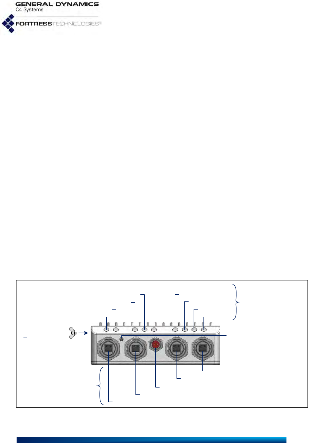
Figure 2.1. ES2440 Front-Panel Ports, Reset Button, LEDs and Grounding Stud Location
LEDs
Ethernet 2—default clear port
Ethernet1
serial port
DC power inlet
ports
Radio4/S4
Radio3/S3
Radio2/S2
Radio1/S1
Ethernet 1/WAN/PoE input—default encrypted port
Ethernet2
Status
Power
Ethernet 3—default clear port
Ethernet3
recessed button screw cap
(reset factory defaults)
grounding stud
left rear corner
ES2440 Hardware Guide: Installation
7
The ES2440 Mesh Point’s Serial port and three Ethernet ports,
Ethernet1/WAN/POE, Ethernet2, and Ethernet3 are located on
the front panel, along with the DC Power inlet and recessed
Reset button (see Figure 2.1).
All ES2440 front-panel ports are protected by captive covers.
Unused ports should remain covered to protect against dust
and other debris. Covered or uncovered, all ES2440 ports are
waterproof.
The recessed button used to restore the running configuration
to factory defaults (Section 3.2) is also located on the front
panel, beneath a protective screw cap.
The LEDs located above the ES2440’s ports are described in
Section 3.1
2.1.3.2 Grounding Stud
On all ES2440 models, the grounding stud is the wing nut
located on the left rear corner of the chassis, viewing the
ES2440 from the front as shown in Figure 2.1 (refer to also to
Figure 2.2).
2.1.3.3 Rear Panel Connectors
The ES2440 rear-panel antenna port configuration depends on
the Mesh Point’s hardware model.
ES2440-3555
Nine antenna connectors are situated on the ES2440-3555
back panel: eight, corresponding by pair to the ES2440’s four
internal radios, as shown below, and one for the ES2440
internal GPS.
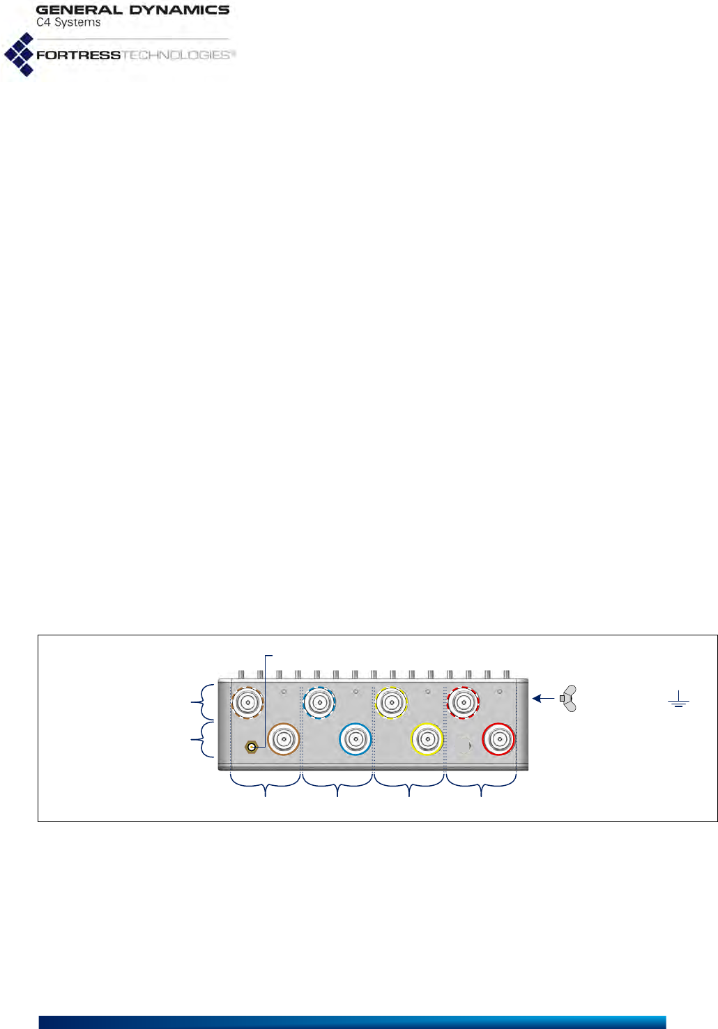
Figure 2.2. ES2440-3555 Back-Panel Antenna Connectors
Antenna port ring labels identify which radio uses to each pair
of ports by color: red, yellow, blue and brown (right-to-left in
Figure 2.2), correspond to radios 1, 2, 3, and 4, respectively.
Solid ring labels identify the radios’ A antenna ports; dashed-
line labels identify B ports. Antenna port labels are printed with
the corresponding radio’s 802.11 capabilities: 802.11a/b/g/n or
802.11a/n.
antenna ports B
GPS antenna port
antenna ports A
Radio 4 Radio 3 Radio 2 Radio 1
grounding stud
ES2440 Hardware Guide: Installation
8
ES2440-3444
The ES2440-3444 is likewise equipped with the appropriate
rear-panel antenna port configuration for the number and type
of radios installed: two for Radio 1, and one for each 4.4 GHz
radio (Radio 2, Radio 3 and Radio 4). The GPS antenna port is
also present in this model, for a total of six rear-panel antenna
ports.
ES2440-35
Five antenna connectors are situated on the ES2440-35 back
panel: four corresponding, by pair, to the ES2440’s two internal
radios, and one for the ES2440 internal GPS.
ES2440-34
The ES2440-34 rear panel is equipped with four antenna ports:
two for Radio 1, one for the 4.4 GHz Radio 2, and the GPS
antenna port.
ES2440-0
Only the GPS antenna port is present on the ES2440-0 chassis
rear panel.
2.2 Connecting the ES2440
CAUTION: Never
plug the ES2440
into a PoE adapter/injec-
tor or DC power supply
other than one obtained
from Fortress specifical-
ly for use with the
ES2440. Using the
wrong power adapter
can damage the ES2440.
The ES2440 can be connected temporarily to preconfigure the
Mesh Point software, and then permanently for deployment.
2.2.1 Connections for Preconfiguration
Mesh Point software should be configured in advance of
deployment. This section provides instructions for temporarily
connecting the ES2440 Mesh Point for preconfiguration.
1Position the Mesh Point so that it operates only within its
safe temperature range.
2Apply power to the ES2440, either through the Ethernet1/
WAN/POE port to PoE+ or through the DC Power inlet to
external power. Refer to Section 2.1.2, Powering Options,
for additional detail.
In either case, you must use a powering device (PoE+
adapter/injector or DC adapter/supply) obtained from
Fortress specifically for use with the ES2440.
3Connect a standard Cat5e cable to one of the ES2440’s
default clear Ethernet ports: Ethernet2 or Ethernet3, and
connect the other end to a computer or a switch on the
wired LAN.
To complete the configuration, refer to the Software GUI Guide
or the Software CLI Guide for instructions on Logging On,
Licensing, and Configuring the Mesh Point software.
ES2440 Hardware Guide: Installation
9
WARNING: To
comply with FCC
regulations, antennas
must be professionally
installed and the install-
er is responsible for en-
suring compliance with
FCC limits.
2.2.2 Connections for Deployment
Review the IMPORTANT SAFETY INFORMATION on page iii
and Safety Requirements in Section 2.1.1 before installing or
operating the ES2440.
2.2.2.1 Connecting the ES2440-3555 or
ES2440-35 for Deployment
Antennas used with the ES2440 must be professionally
installed and must conform to FCC EIRP (Effective Isotropic
Radiated Power) limitations. All antennas must have 50 Ohms
impedance.
1Ground the ES2440-3555/35 by connecting a ground wire
to the grounding stud located on the left rear corner of the
chassis (refer to Figure 2.1).
CAUTION: The
FCC requires co-
located radio antennas
to be at least 9.8" (25 cm)
apart. The Mesh Point’s
antenna connectors are
closer than this. Avoid
directly mounting two
or more antennas to the
Mesh Point’s rear-panel
connectors.
2If your deployment uses Radio 1, connect a standard
2.4 GHz- or 5 GHz-capable antenna with an N-type male
connector to antenna port A for Radio 1 (Ant1A).
If the radio will be configured for MIMO (multiple-input and
multiple-output) operation, you must also connect a second
such antenna to the radio’s antenna port B (Ant1B).
3If your deployment uses Radio 2 (and Radio 3 and Radio 4,
if present), connect an antenna cable with a N-type male
connector to the antenna port(s) for the radio(s) you will
use: Ant2A (and Ant3A and Ant4A, if present). Connect a
high-gain omnidirectional or directional antenna to the other
end(s) of these cable(s).
CAUTION: Out-
door antennas,
connectors, and cables
must be waterproof.
If the radio(s) will be configured for MIMO operation, you
must also connect a second such antenna, for each radio
that will be so configured, to the radio’s antenna port B:
Ant2B (and Ant3B and Ant4B, if present).
4If the Mesh Point’s GPS function will be used, connect an
SMA GPS antenna to the GPS antenna port.
5Apply power to the ES2440-3555/35, either through the
Ethernet1/WAN/POE port to PoE+ or through the DC Power
inlet to external power. Refer to Section 2.1.2, Powering
Options, for additional detail.
In either case, you must use a powering device (PoE+
adapter/injector or DC adapter/supply) obtained from
Fortress specifically for use with the ES2440.
6If your deployment includes Ethernet network connections,
make them now: using standard Cat5e cable(s) for a
through connection to Ethernet1/WAN/POE (default
encrypted), and/or to connect Ethernet2 and/or Ethernet3
(both default clear).

ES2440 Hardware Guide: Installation
10
NOTE: LED indica-
tors are covered in
Section 3.1
7Verify that the Power LED illuminates, as well as the
corresponding LEDs for all connected ports and enabled
radio(s).
2.2.2.2 Connecting the ES2440-3444 or
ES2440-34 for Deployment
Connection procedures for the ES2440-3444/34 are identical
to those provided for the ES2440-3555 above, except that
MIMO is not an option for its 4.4 GHz radios (Radio 2, and
Radio 3 and Radio 4, if present). Only a single antenna port is
therefore present for each of these radios, and the second part
of Step 3 in Section 2.2.2.1 does not apply.
2.2.2.3 Connecting the ES2440-0 for Deployment
1Ground the ES2440-0 by connecting a ground wire to the
ES2440’s grounding stud located on the left rear corner of
the chassis (refer to Figure 2.1).
CAUTION: Out-
door antennas,
connectors, and cables
must be waterproof.
2If the Mesh Point’s GPS function will be used, connect an
SMA GPS antenna to the GPS antenna port.
3Connect the front-panel Ethernet port(s), according to the
requirements of your deployment, using standard Cat5e
cable(s) to Ethernet1/WAN/POE (default encrypted), and/or
to Ethernet2 and/or Ethernet3 (both default clear).
NOTE: If you have
obtained an alter-
native powering device
from Fortress, refer to
Section 2.1.2, Powering
Options, for detailed in-
structions.
4Connect the DC power connector/cable assembly included
with the ES2440-0 to a 11–32 VDC power source, and
apply power to the ES2440-0 through the DC Power inlet.
5Verify that the Power LED illuminates, as well as the
corresponding LEDs for all connected Ethernet ports.
2.2.3 Disconnection
To disconnect and power down the ES2440, depending on the
power source in use by the ES2440:
Remove AC power from the PoE+ adapter/injector to which
the ES2440 is connected by unplugging the adapter/
injector’s power cord from the wall.
or
Remove DC power from the ES2440 by unplugging the DC
power cable connector from the ES2440’s DC Power inlet.
ES2440 Hardware Guide: Installation
11
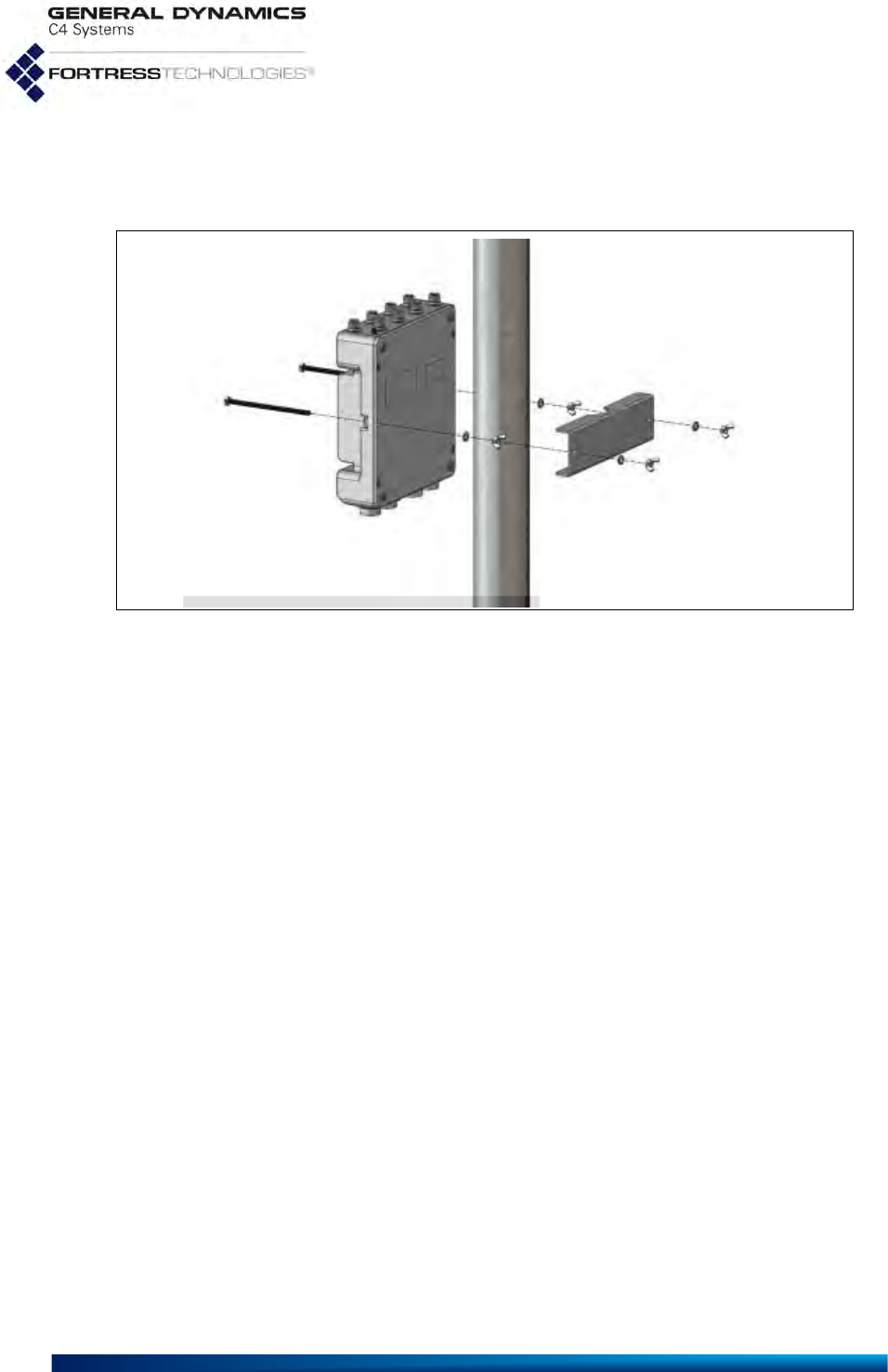
2.3 Mast Mounting the ES2440
A Mast-Mounting Kit is included with the ES2440-3555 and
ES2440-3444. The ES2440-0 ships without it.
Figure 2.3. Mast mounting the ES2440
Mast-mounting hardware accommodates masts from 1.5" to 3"
in diameter.
1Fit the two hex bolts through the center mounting holes
along the ES2440's sides, top to bottom.
2Fix each bolt to the ES2440 chassis with a split-lock
washer followed by a wing nut, tightened securely to the
underside of the chassis.
3Position the ES2440 at the desired position on the mast,
with the underside of the chassis facing toward the mast
and the front panel facing down, as shown in Figure 2.3.
4Sandwiching the mast between the underside of the
ES2440 and the mounting bracket, fit the mast into the
toothed cut-outs in the mounting bracket and insert the bolt
shafts extending from the chassis through the holes in the
bracket.
5Place a slip-lock washer and then a wing nut on each of the
bolt ends, and tighten the nuts until the washers are
flattened against the mounting bracket.

ES2440 Hardware Guide: LEDs and Button Operation
12
Chapter 3
LEDs and Button Operation
3.1 Front-Panel LED Indicators
The ES2440 Mesh Point features nine LEDs on the front panel
(shown in Figure 2.1, on page 6).
Power, Status and Ethernet LEDs are present on all three
ES2440 hardware models, and their behaviors have the same
meanings across all models.
Power
can exhibit:
solid green - Mesh Point is powered on and operating
normally.
off - Mesh Point is powered off.
slow-flash green - Mesh Point is booting.
Status
can exhibit:
slow-flash green - Auto-Config configuration or upgrade
distribution is in progress.
Ethernet1
,
Ethernet2
,
Ethernet3
can exhibit:
solid green - Link has been established.
intermittent green - Traffic is passing on the port.
On the ES2440-3555 and ES2440-3444, the four LEDs on the
right-hand side of the front panel correspond to the Mesh
Point’s internal radios.
Radio1
,
Radio2
, (and
Radio3
and
Radio4
, when present)
can exhibit:
solid green - Radio is on.
intermittent green - Radio is passing traffic.
off - Radio is off or Mesh Point’s RF Kill function is enabled.
On the ES2440-0 the four LEDs on the right side of the front
panel are labeled S1, S2, S3, and S4 and are reserved for future
functionality.

ES2440 Hardware Guide: LEDs and Button Operation
13
3.2 Recessed Button Operation
The single recessed button on the ES2440 front panel (shown
in Figure 2.1) returns the ES2440 Mesh Point to the factory
default configuration.
The button is covered by a screw cap that you must remove, in
order to access the button. You must replace the screw cap,
in order to maintain the watertight integrity of the ES2440
chassis.
To restore default settings, depress and hold the button for 10
seconds. All current configuration information on the running
boot partition will be lost.
Table 3.1. LED Indicators in the ES2440
color behavior Power Status
Ethernet1,
Ethernet2,
Ethernet3
Link/Act
Radio1, Radio2,
Radio3, Radio4a
green
solid normal operation - link established radio ON
slow flash booting Auto-Config
distribution --
intermittent - - passing traffic passing traffic
off powered OFF - - radio OFF
or
RF Kill enabled
a. Present only on radio-equipped ES2440s, according to the number of radios installed. Corresponding LEDs S1,
S2, S3, and S4 on ES2440s equipped with fewer or no radios are reserved for future functionality.
ES2440 Hardware Guide: Specifications
14
Chapter 4
Specifications
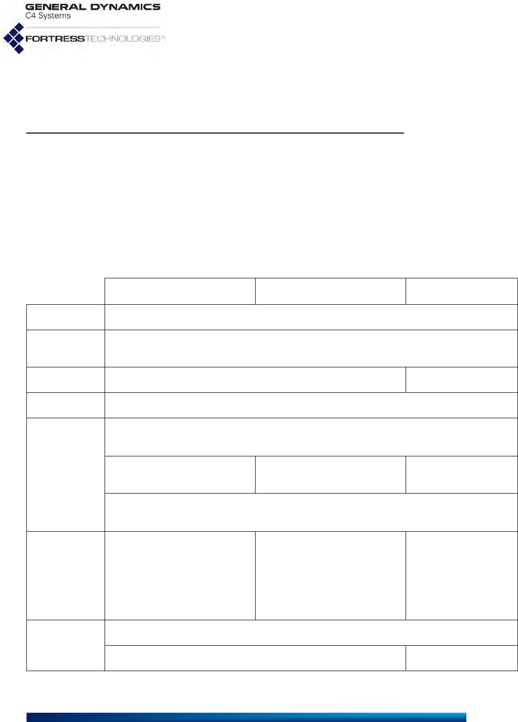
4.1 Hardware Specifications
4.1.1 Physical Specifications
ES2440-3555/35 ES2440-3444/34 ES2440-0
form factor: mountable, compact, rugged chassis
dimensions: 2.75" H x 8.5” W x 10.75” D
(6.99 cm x 21.59 cm x 27.3 cm)
weight:
7.5 lbs (3.4 kg)
/
7 lbs (3.18 kg)
6.5 lbs. (2.95 kg)
power supply: 802.3at POE+ or 11–32 VDC
connections:
three RJ-45 10/100/1000 Mbps Ethernet ports with tethered caps
one RJ-45 serial port with tethered cap
eight/four N-type radio antenna
ports (female) five/three N-type radio antenna
ports (female) no radio antenna ports
one SMA antenna port for GPS receiver (female, passive or active)
one 11–32 VDC power input port with tethered cap
radios:
Radio1a:
400 mW (peak power) 802.11a/b/g/n
Radio2a
(& Radio3a, Radio4a, if present):
631 mW (peak power) 802.11a/n
Radio1a:
400 mW (peak power) 802.11a/b/g/n
Radio2
(& Radio3, Radio4, if present):
800mW (peak power)
802.11a/n 4.4GHz
n/a
system & port
LED indicators:
Power, Status, Ethernet1 Link/Act, Ethernet2 Link/Act, Ethernet3 Link/Act
Radio1, Radio2, Radio3, Radio4 S1, S2, S3, S4 (future)
a. supports MIMO
ES2440 Hardware Guide: Specifications
15
4.1.2 Environmental Specifications
4.1.3 Compliance and Standards
The Fortress ES2440-3555 is certified by the Wi-Fi Alliance®
for the following standards:
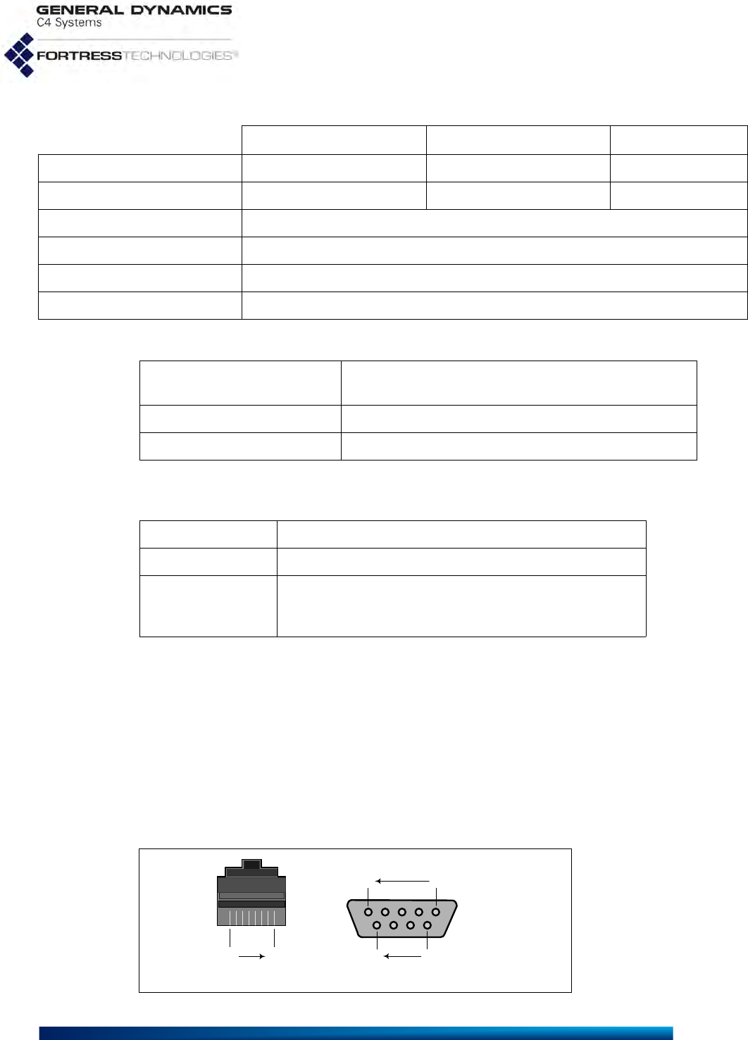
4.2 RJ45-to-DB9 Serial Port Adapter
An RJ45-to-DB9 adapter (included with each Mesh Point) is
required in order to connect the Mesh Point’s serial port to a
DB9 terminal connection.
Figure 4.1 shows the pin numbers for the two connectors. With
the RJ45 connector facing you and oriented with the tab
receptacle up, pins are numbered from right to left, as shown.
With the DB9 connector facing you and oriented with the wide
side up, pins are numbered from right to left, top to bottom.
Figure 4.1. RJ45 and DB9 Pin Numbering
ES2440-3555, ES2440-3444 ES2440-35, ES2440-34 ES2440-0
maximum power draw: 40 W 32 W 25 W
maximum heat dissipation: 137 BTUs/hr 110 BTUs/hr 85 BTUs/hr
cooling: Convection Cooled
operating temperature: -40º–158º F (-40º–70º C)
operating relative humidity: 5%–95% (non-condensing)
storage temperature: -40º–158º F (-40º–70º C)
emissions/immunity: CE, FCC, IC, ETSI, CB Test,
MIL-STD 464A, MIL-STD 461F
vibration: MIL-STD 810G
weather resistance: IP67 submersible
IEEE: 802.11a/b/g/n
security: WPA™, WPA2™—Personal and Enterprise
EAP types: EAP-TLS, EAP-TTLS/MSCHAPv2,
PEAPv0/EAP-MSCHAPv2, PEAPv1/EAP-GTC,
EAP-SIM, EAP-AKA, EAP-FAST
RJ45 DB9
...5 1
female pins
96...
pins 8 1
ES2440 Hardware Guide: Specifications
16
Table 4.1 shows the serial port adapter pin-outs.
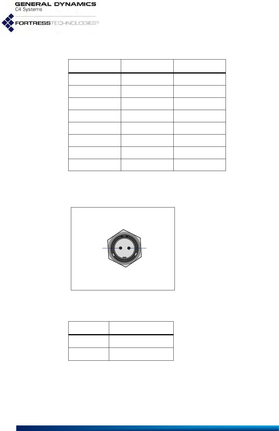
4.3 2-Pin DC Input Connector
The ES2440 Mesh Point uses a 2-pin connector to input DC
power.
Figure 4.2. 2-pin Power Connector Pins
Table 4.2 shows DC power connector pin-outs.
Table 4.1. RJ45-to-DBP Adapter Pin-Outs
RJ45 pin DB9 pin standard color
1 8 grey
26brown
32yellow
4 5 green
5-red
6 3 black
7 4 orange
87blue
pin Bpin A
Table 4.2. ES2440 DC Power Connector Pin-Outs
pin signal
A11–32 VDC
BGround

ES2440 Hardware Guide: Index
I
Index
Numerics
4.4 GHz radios vii, 2, 14
802.11a/b/g/n
see radios
A
antennas
connecting 9, 10
connector specifications 14
precautions 5, 6, 9, 10
restrictions 9
C
compliance 15
Canada vi
FCC v
standards 15
D
DB9-to-RJ-45 adapter 15–16
DC power input 7, 8, 9, 10, 14
connector pin-outs 16
dimensions 14
E
earthing 5, 6, 9, 10
emissions v, 15
environmental specifications 14
Ethernet
connecting 8, 9, 10
LEDs 12
port locations 7
specifications 14
see also PoE
F
FCC
emissions compliance v
TDWR information iii–v
fuse 4
G
GPS 2, 7, 8, 9, 10
grounding 5, 6, 9, 10
H
hardware
mast mounting 3, 11
models 2
safety requirements iii, 4–5
specifications 14–15
I
installation 8–10
safety requirements 4–5
interference
see emissions
M
mast mounting 11
MIMO 2, 14
antenna ports 7
antennas 9
models 2
O
operating temperature 4, 15
P
pin-outs
DB9-to-RJ-45 adapter 15–16
DC power connector 16
PoE 6, 8
port location 7
specifications 14
ports
connecting 8–10
LEDs 12
locations 6–7
specifications 14
powering 4, 5–6, 8, 9
PoE 7
supply specifications 14
precautions
see safety

ES2440 Hardware Guide: Index
II
R
radios 2, 14
connecting antennas 7, 9
LEDs 12–13
precautions vii, 2, 9
safety requirements 5
specifications 14
RJ-45-to-DB9 adapter 15–16
S
safety
precautions iii, 1, 5, 8, 9
requirements 4–5
see also specifications
serial port
adapter 15–16
location 7
specifications 14–15
T
TDWR iii–v
temperature 4, 15
V
VDC input 7, 8, 9, 10, 14
connector pin-outs 16
vibration 15