Fortress Technologies ES520 Dual Radio Access Point/Bridge User Manual ES520 Deployable Mesh Point Hardware Guide rev 2
Fortress Technologies, Inc. Dual Radio Access Point/Bridge ES520 Deployable Mesh Point Hardware Guide rev 2
UserManual.wiki
>
Fortress Technologies
>
ES520 User Manual
User Manual
Navigation menu
Upload a User Manual
Namespaces
Wiki Guide
HTML
PDF
Info
Views
User Manual
Discussion / Help
Navigation
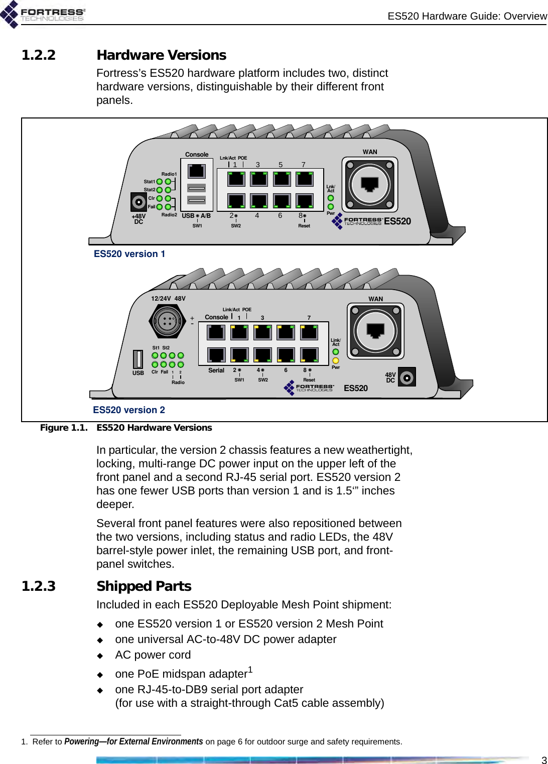
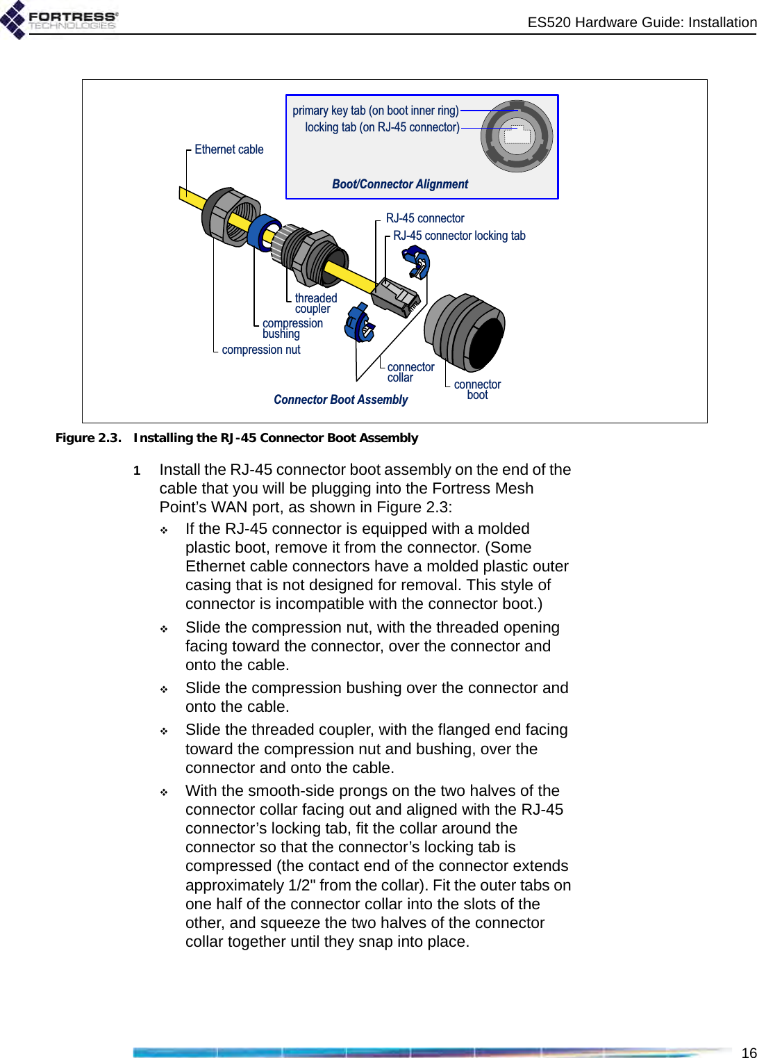
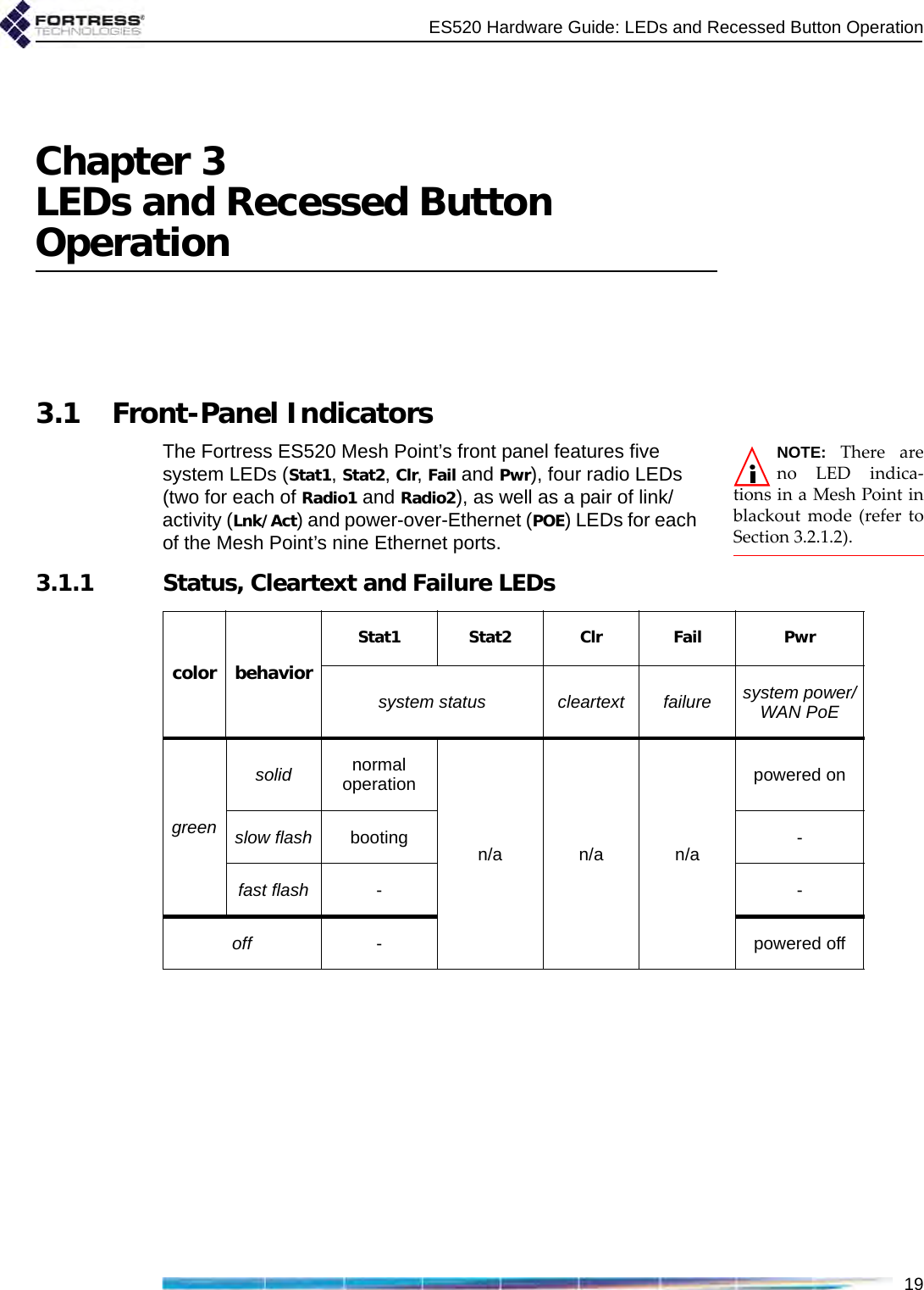
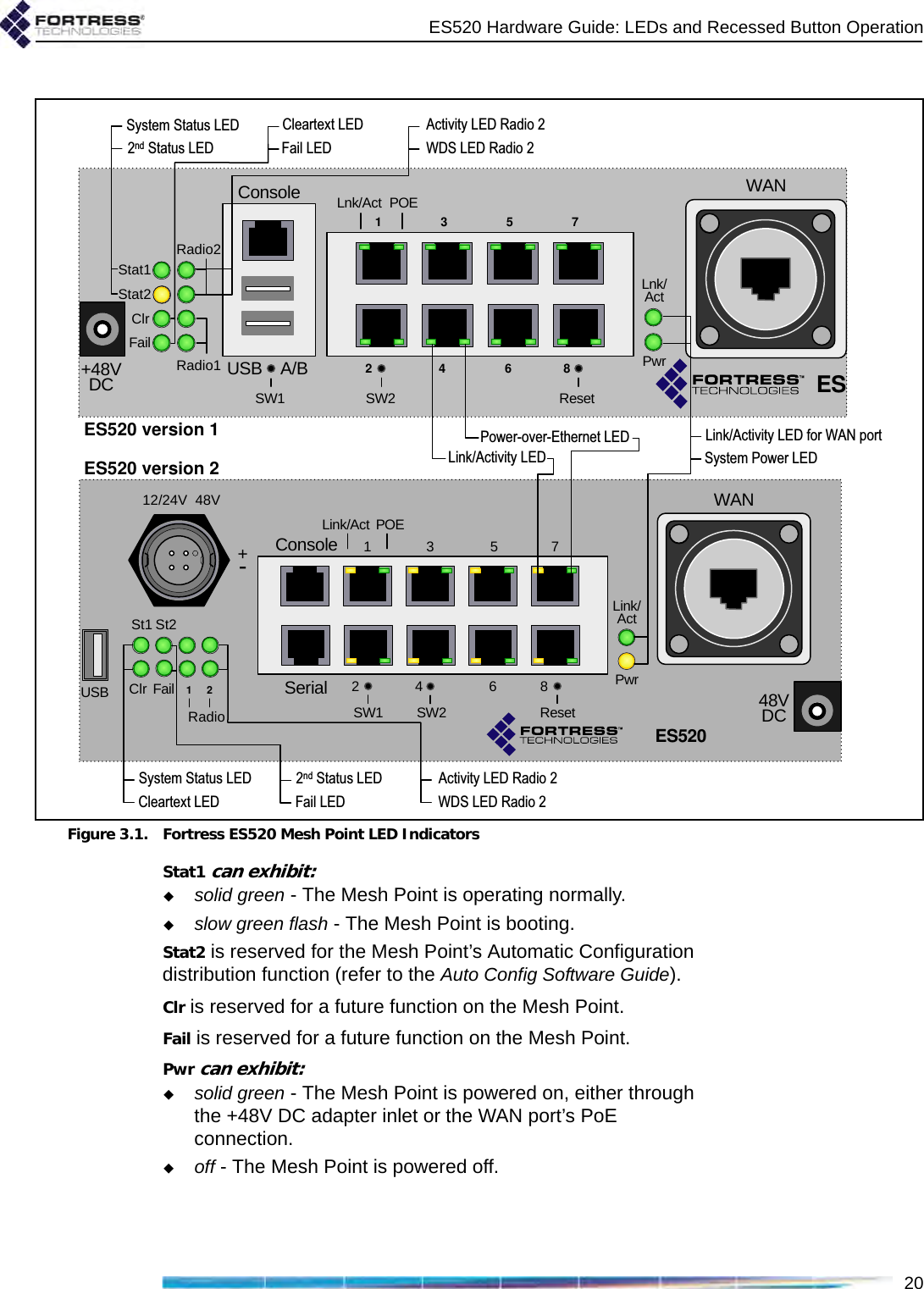
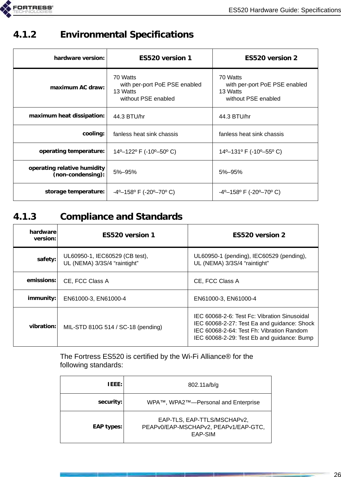
![ES520 Hardware Guidei009-00028-00r2Fortress ES520 Deployable Mesh Point [rev.2]Copyright © 2011 Fortress Technologies, Inc. All rights reserved.This document contains proprietary information protected by copyright. No part of this document may be reproduced or transmitted in any form or by any means, electronic or mechanical, without written permission of Fortress Technologies, 1 Technology Park Drive, Westford, MA 01886-3140, except as specified in the Product Warranty and License Terms.FORTRESS TECHNOLOGIES, INC., MAKES NO WARRANTY OF ANY KIND WITH REGARD TO THIS MATERIAL, INCLUDING BUT NOT LIMITED TO THE IMPLIED WARRANTIES OF MERCHANTABILITY AND FITNESS FOR A PARTICULAR PURPOSE. FORTRESS TECHNOLOGIES, INC. SHALL NOT BE LIABLE FOR ERRORS CONTAINED HEREIN OR FOR INCIDENTAL OR CONSEQUENTIAL DAMAGES IN CONNECTION WITH THE FURNISHING, PERFORMANCE OR USE OF THIS MATERIAL. THE INFORMATION IN THIS DOCUMENT IS SUBJECT TO CHANGE WITHOUT NOTICE.The Fortress Technologies and AirFortress logos and AirFortress and are registered trademarks; Multi-Factor Authentication, Unified Security Model, Wireless Link Layer Security and Three Factor Authentication (TFA) are trademarks of Fortress Technologies, Inc. The technology behind Wireless Link Layer Security™ enjoys U.S. and international patent protection under patent number 5,757,924.All other trademarks mentioned in this document are the property of their respective owners.IMPORTANT FCC INFORMATIONThe Federal Communications Commission has released Office of Engineering and Technology Laboratory Division Knowledge Database (KDB) 44399, which refines the definition of Dynamic Frequency Selection (DFS) support. Since this device has the ability to use frequencies covered by DFS, KDB 443999 must be followed. It is published in full on the FCC web site: https://apps.fcc.gov/oetcf/kdb/forms/FTSSearchResultPage.cfm?switch=P&id=41732In order to support FCC KDB 443999, Fortress has limited the use of certain frequencies within the 5400–5725 MHz range. Specifically, the frequencies defined by the FCC as being of primary interest are those in the 5600–5650 MHz range, which correspond to 802.11a channels 120, 124, and 128. In order to comply with the KDB 443999, these channels have been removed from use, or notched. Notched channels are unavailable for use on this device.KDB 44399 provides additional restrictions on the use of channels within 30 MHz of notched channels when the device is within 35 km of a Terminal Doppler Weather Radar (TDWR) installation. Affected channels 116, 132, and 136 serve as a guard of 30 MHz around the critical notched frequencies. Guard frequencies are unavailable for use on this device by default. The FCC allows these channels to be used, however, as long as the device is not within 35 km of a TDWR installation, as described in this excerpt of KDB 443999:Any installation of either a master or a client device within 35 km of a TDWR location shall be separated by at least 30 MHz (center-to-center) from the TDWR operating frequency.In some instances it is possible that a device may be within 35 km of multiple TDWRs. In this case the device must ensure that it avoids operation within 30 MHz for each of the TDWRs. This requirement applies even if the master is outside the 35 km radius but communicates with outdoor clients which may be within the 35 km radius of the TDWRs.The requirement for ensuring 30 MHz frequency separation is based on the best information available to date. If interference is not eliminated, a distance limitation based on line-of-sight from TDWR will need to be used. Please refer to the original KDB 443999 as posted on the FCC web site for the complete text.](https://usermanual.wiki/Fortress-Technologies/ES520/User-Guide-1666085-Page-2.png)
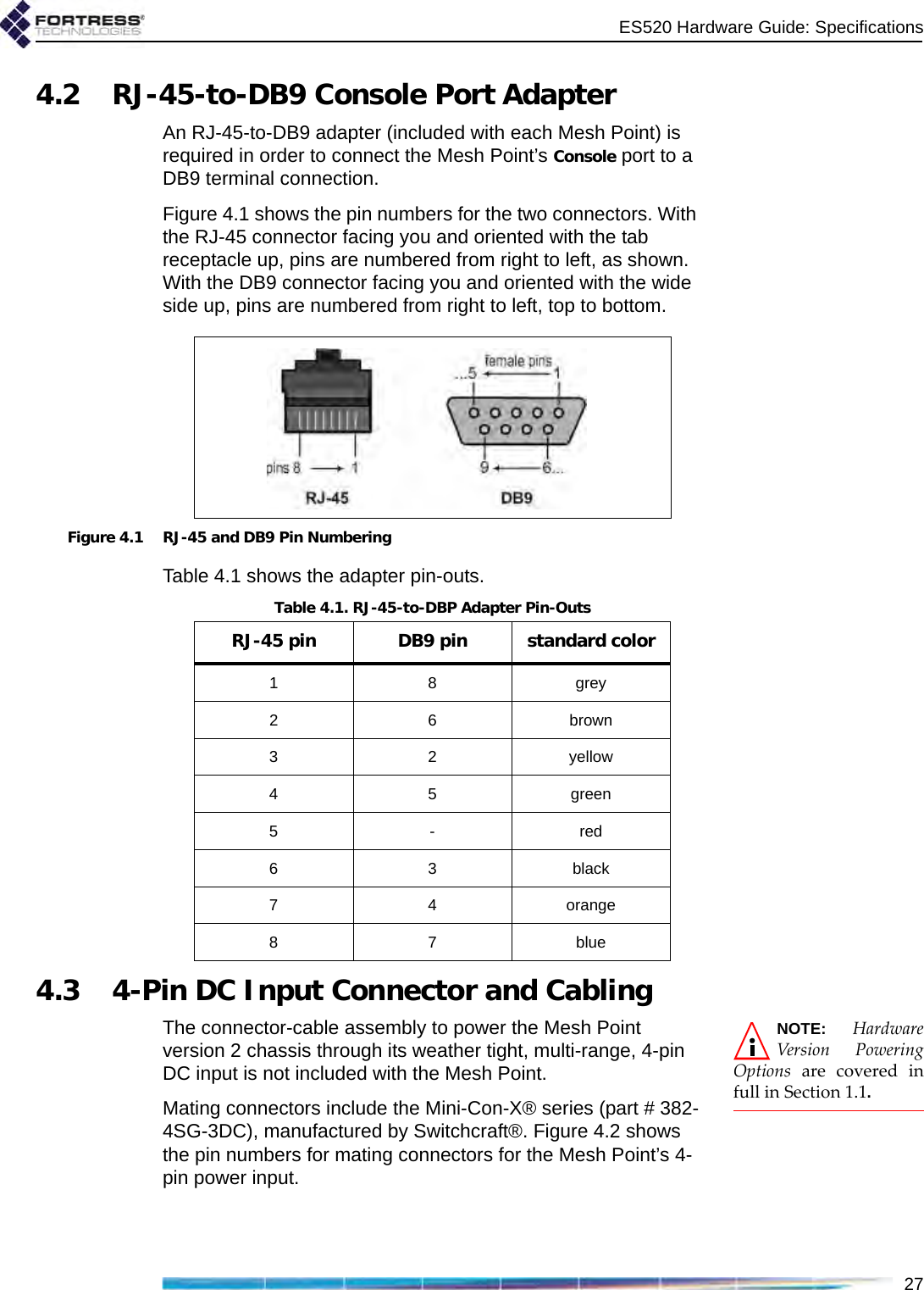
![ES520 Hardware GuideiiIn order to enable channels 116, 132, and/or 136, please contact Fortress to obtain a special license. This license will be issued after it is confirmed that the installation is not within 30 MHz and 35 km of registered TDWR sites. The following table (provided by the FCC in KDB 443999 published on 10/14/2010) describes the locations of TDWR sites, as well as the frequencies at which these sites operate:TDWR Location Information TERRAIN ELEVATION (MSL) [ft] ANTENNA HEIGHT ABOVE TERRAIN [ft] STATE CITY LONGITUDE LATITUDE FREQUENCY AZ PHOENIX W 112 09 46 N 33 25 14 5610 MHz 1024 64 CO DENVER W 104 31 35 N 39 43 39 5615 MHz 5643 64 FL FT LAUDERDALE W 080 20 39 N 26 08 36 5645 MHz 7 113 FL MIAMI W 080 29 28 N 25 45 27 5605 MHz 10 113 FL ORLANDO W 081 19 33 N 28 20 37 5640 MHz 72 97 FL TAMPA W 082 31 04 N 27 51 35 5620 MHz 14 80 FL WEST PALM BEACH W 080 16 23 N 26 41 17 5615 MHz 20 113 GA ATLANTA W 084 15 44 N 33 38 48 5615 MHz 962 113 IL MCCOOK W 087 51 31 N 41 47 50 5615 MHz 646 97 IL CRESTWOOD W 087 43 47 N 41 39 05 5645 MHz 663 113 IN INDIANAPOLIS W 086 26 08 N 39 38 14 5605 MHz 751 97 KS WICHITA W 097 26 13 N 37 30 26 5603 MHz 1270 80 KY COVINGTON CINCINNATI W 084 34 48 N 38 53 53 5610 MHz 942 97 KY LOUISVILLE W 085 36 38 N 38 02 45 5646 MHz 617 113 LA NEW ORLEANS W 090 24 11 N 30 01 18 5645 MHz 2 97 MA BOSTON W 070 56 01 N 42 09 30 5610 MHz 151 113 MD BRANDYWINE W 076 50 42 N 38 41 43 5635 MHz 233 113 MD BENFIELD W 076 37 48 N 39 05 23 5645 MHz 184 113 MD CLINTON W 076 57 43 N 38 45 32 5615 MHz 249 97 MI DETROIT W 083 30 54 N 42 06 40 5615 MHz 656 113 MN MINNEAPOLIS W 092 55 58 N 44 52 17 5610 MHz 1040 80 MO KANSAS CITY W 094 44 31 N 39 29 55 5605 MHz 1040 64 MO SAINT LOUIS W 090 29 21 N 38 48 20 5610 MHz 551 97 MS DESOTO COUNTY W 089 59 33 N 34 53 45 5610 MHz 371 113 NC CHARLOTTE W 080 53 06 N 35 20 14 5608 MHz 757 113 NC RALEIGH DURHAM W 078 41 50 N 36 00 07 5647 MHz 400 113 NJ WOODBRIDGE W 074 16 13 N 40 35 37 5620 MHz 19 113 NJ PENNSAUKEN W 075 04 12 N 39 56 57 5610 MHz 39 113 NV LAS VEGAS W 115 00 26 N 36 08 37 5645 MHz 1995 64 NY FLOYD BENNETT FIELD W 073 52 49 N 40 35 20 5647 MHz 8 97 OH DAYTON W 084 07 23 N 40 01 19 5640 MHz 922 97 OH CLEVELAND W 082 00 28 N 41 17 23 5645 MHz 817 113 OH COLUMBUS W 082 42 55 N 40 00 20 5605 MHz 1037 113 OK AERO. CTR TDWR #1 W 097 37 31 N 35 24 19 5610 MHz 1285 80 OK AERO. CTR TDWR #2 W 097 37 43 N 35 23 34 5620 MHz 1293 97 OK TULSA W 095 49 34 N 36 04 14 5605 MHz 712 113 OK OKLAHOMA CITY W 097 30 36 N 35 16 34 5603 MHz 1195 64 PA HANOVER W 080 29 10 N 40 30 05 5615 MHz 1266 113 PR SAN JUAN W 066 10 46 N 18 28 26 5610 MHz 59 113 TN NASHVILLE W 086 39 42 N 35 58 47 5605 MHz 722 97 TX HOUSTON INTERCONTL W 095 34 01 N 30 03 54 5605 MHz 154 97](https://usermanual.wiki/Fortress-Technologies/ES520/User-Guide-1666085-Page-3.png)