Fortress Technologies ES520 Dual Radio Access Point/Bridge User Manual ES520 Deployable Mesh Point Hardware Guide rev 2
Fortress Technologies, Inc. Dual Radio Access Point/Bridge ES520 Deployable Mesh Point Hardware Guide rev 2
User Manual

Fortress Security System
ES520
Deployable Mesh Point
Hardware Guide
www.fortresstech.com
© 2011 Fortress Technologies

ES520 Hardware Guide
i
009-00028-00r2
Fortress ES520 Deployable Mesh Point [rev.2]
Copyright © 2011 Fortress Technologies, Inc. All rights reserved.
This document contains proprietary information protected by copyright. No part of this
document may be reproduced or transmitted in any form or by any means, electronic or
mechanical, without written permission of Fortress Technologies, 1 Technology Park Drive,
Westford, MA 01886-3140, except as specified in the Product Warranty and License
Terms.
FORTRESS TECHNOLOGIES, INC., MAKES NO WARRANTY OF ANY KIND WITH
REGARD TO THIS MATERIAL, INCLUDING BUT NOT LIMITED TO THE IMPLIED
WARRANTIES OF MERCHANTABILITY AND FITNESS FOR A PARTICULAR PURPOSE.
FORTRESS TECHNOLOGIES, INC. SHALL NOT BE LIABLE FOR ERRORS
CONTAINED HEREIN OR FOR INCIDENTAL OR CONSEQUENTIAL DAMAGES IN
CONNECTION WITH THE FURNISHING, PERFORMANCE OR USE OF THIS
MATERIAL. THE INFORMATION IN THIS DOCUMENT IS SUBJECT TO CHANGE
WITHOUT NOTICE.
The Fortress Technologies and AirFortress logos and AirFortress and are registered
trademarks; Multi-Factor Authentication, Unified Security Model, Wireless Link Layer
Security and Three Factor Authentication (TFA) are trademarks of Fortress Technologies,
Inc. The technology behind Wireless Link Layer Security™ enjoys U.S. and international
patent protection under patent number 5,757,924.
All other trademarks mentioned in this document are the property of their respective
owners.
IMPORTANT FCC INFORMATION
The Federal Communications Commission has released Office of Engineering and Technology
Laboratory Division Knowledge Database (KDB) 44399, which refines the definition of Dynamic
Frequency Selection (DFS) support. Since this device has the ability to use frequencies covered
by DFS, KDB 443999 must be followed. It is published in full on the FCC web site:
https://apps.fcc.gov/oetcf/kdb/forms/FTSSearchResultPage.cfm?switch=P&id=41732
In order to support FCC KDB 443999, Fortress has limited the use of certain frequencies within
the 5400–5725 MHz range. Specifically, the frequencies defined by the FCC as being of primary
interest are those in the 5600–5650 MHz range, which correspond to 802.11a channels 120, 124,
and 128. In order to comply with the KDB 443999, these channels have been removed from use,
or notched. Notched channels are unavailable for use on this device.
KDB 44399 provides additional restrictions on the use of channels within 30 MHz of notched
channels when the device is within 35 km of a Terminal Doppler Weather Radar (TDWR)
installation. Affected channels 116, 132, and 136 serve as a guard of 30 MHz around the critical
notched frequencies. Guard frequencies are unavailable for use on this device by default. The
FCC allows these channels to be used, however, as long as the device is not within 35 km of a
TDWR installation, as described in this excerpt of KDB 443999:
Any installation of either a master or a client device within 35 km of a TDWR location shall
be separated by at least 30 MHz (center-to-center) from the TDWR operating frequency.
In some instances it is possible that a device may be within 35 km of multiple TDWRs. In
this case the device must ensure that it avoids operation within 30 MHz for each of the
TDWRs. This requirement applies even if the master is outside the 35 km radius but
communicates with outdoor clients which may be within the 35 km radius of the TDWRs.
The requirement for ensuring 30 MHz frequency separation is based on the best
information available to date. If interference is not eliminated, a distance limitation based
on line-of-sight from TDWR will need to be used.
Please refer to the original KDB 443999 as posted on the FCC web site for the complete text.

ES520 Hardware Guide
ii
In order to enable channels 116, 132, and/or 136, please contact Fortress to obtain a special
license. This license will be issued after it is confirmed that the installation is not within 30 MHz and
35 km of registered TDWR sites. The following table (provided by the FCC in KDB 443999
published on 10/14/2010) describes the locations of TDWR sites, as well as the frequencies at
which these sites operate:
TDWR Location Information TERRAIN
ELEVATION
(MSL) [ft]
ANTENNA
HEIGHT ABOVE
TERRAIN [ft]
STATE CITY LONGITUDE LATITUDE FREQUENCY
AZ PHOENIX W 112 09 46 N 33 25 14 5610 MHz 1024 64
CO DENVER W 104 31 35 N 39 43 39 5615 MHz 5643 64
FL FT LAUDERDALE W 080 20 39 N 26 08 36 5645 MHz 7 113
FL MIAMI W 080 29 28 N 25 45 27 5605 MHz 10 113
FL ORLANDO W 081 19 33 N 28 20 37 5640 MHz 72 97
FL TAMPA W 082 31 04 N 27 51 35 5620 MHz 14 80
FL WEST PALM BEACH W 080 16 23 N 26 41 17 5615 MHz 20 113
GA ATLANTA W 084 15 44 N 33 38 48 5615 MHz 962 113
IL MCCOOK W 087 51 31 N 41 47 50 5615 MHz 646 97
IL CRESTWOOD W 087 43 47 N 41 39 05 5645 MHz 663 113
IN INDIANAPOLIS W 086 26 08 N 39 38 14 5605 MHz 751 97
KS WICHITA W 097 26 13 N 37 30 26 5603 MHz 1270 80
KY COVINGTON
CINCINNATI W 084 34 48 N 38 53 53 5610 MHz 942 97
KY LOUISVILLE W 085 36 38 N 38 02 45 5646 MHz 617 113
LA NEW ORLEANS W 090 24 11 N 30 01 18 5645 MHz 2 97
MA BOSTON W 070 56 01 N 42 09 30 5610 MHz 151 113
MD BRANDYWINE W 076 50 42 N 38 41 43 5635 MHz 233 113
MD BENFIELD W 076 37 48 N 39 05 23 5645 MHz 184 113
MD CLINTON W 076 57 43 N 38 45 32 5615 MHz 249 97
MI DETROIT W 083 30 54 N 42 06 40 5615 MHz 656 113
MN MINNEAPOLIS W 092 55 58 N 44 52 17 5610 MHz 1040 80
MO KANSAS CITY W 094 44 31 N 39 29 55 5605 MHz 1040 64
MO SAINT LOUIS W 090 29 21 N 38 48 20 5610 MHz 551 97
MS DESOTO COUNTY W 089 59 33 N 34 53 45 5610 MHz 371 113
NC CHARLOTTE W 080 53 06 N 35 20 14 5608 MHz 757 113
NC RALEIGH DURHAM W 078 41 50 N 36 00 07 5647 MHz 400 113
NJ WOODBRIDGE W 074 16 13 N 40 35 37 5620 MHz 19 113
NJ PENNSAUKEN W 075 04 12 N 39 56 57 5610 MHz 39 113
NV LAS VEGAS W 115 00 26 N 36 08 37 5645 MHz 1995 64
NY FLOYD BENNETT
FIELD W 073 52 49 N 40 35 20 5647 MHz 8 97
OH DAYTON W 084 07 23 N 40 01 19 5640 MHz 922 97
OH CLEVELAND W 082 00 28 N 41 17 23 5645 MHz 817 113
OH COLUMBUS W 082 42 55 N 40 00 20 5605 MHz 1037 113
OK AERO. CTR TDWR #1 W 097 37 31 N 35 24 19 5610 MHz 1285 80
OK AERO. CTR TDWR #2 W 097 37 43 N 35 23 34 5620 MHz 1293 97
OK TULSA W 095 49 34 N 36 04 14 5605 MHz 712 113
OK OKLAHOMA CITY W 097 30 36 N 35 16 34 5603 MHz 1195 64
PA HANOVER W 080 29 10 N 40 30 05 5615 MHz 1266 113
PR SAN JUAN W 066 10 46 N 18 28 26 5610 MHz 59 113
TN NASHVILLE W 086 39 42 N 35 58 47 5605 MHz 722 97
TX HOUSTON
INTERCONTL W 095 34 01 N 30 03 54 5605 MHz 154 97

ES520 Hardware Guide
iii
In addition, the FCC recommends that all operators and installers register with the WISPA
database used by government agencies to quickly find devices that may be causing interference
and notify their owners/operators to shut them down. This registration is not required, but Fortress
strongly recommends that all systems be registered, as described in this excerpt of KDB 44399:
A voluntary WISPA sponsored database has been developed that allows operators and
installers to register the location information of the UNII devices operating outdoors in the
5470 – 5725 MHz band within 35 km of any TDWR location (see
http://www.spectrumbridge.com/udia/home.aspx). This database may be used by
government agencies in order to expedite resolution of any interference to TDWRs.
KDB 443999 further specifies that the requirements of KDB 594280 must also be met.
KDB 594280 is published in full on the FCC web site:
https://apps.fcc.gov/oetcf/kdb/forms/FTSSearchResultPage.cfm?switch=P&id=39498.
This device meets KDB 594280 by not allowing any configuration options to be made such that the
device could be taken out of compliance. There is no ability for the user to change country codes
or to select power levels that would take the device out of compliance.
For customers such as the U.S. military or others willing to produce evidence that particular
devices will be used only outside of the United States, a special license can be obtained from
Fortress that will allow those devices the option of selecting a different, non-U.S. country code.
Fortress creates such licenses only for those customers who offer proof of non-U.S. device usage,
and licenses are specific to particular devices and are not transferrable. Devices having such a
license should NOT be considered to be compliant with FCC regulatory requirements. Please
contact Fortress with questions about these special licences.
Only software that has been signed by Fortress using the Fortress private key can be loaded onto
a Fortress device, thus insuring that no software other than that which is controlled and signed by
Fortress can by loaded onto the device.
FCC EMISSIONS COMPLIANCE STATEMENT
THIS EQUIPMENT HAS BEEN TESTED AND FOUND TO COMPLY
WITH THE LIMITS FOR A CLASS A DIGITAL DEVICE, PURSUANT TO
PART 15 OF THE FCC RULES. THESE LIMITS ARE DESIGNED TO
PROVIDE REASONABLE PROTECTION AGAINST HARMFUL
INTERFERENCE WHEN THE EQUIPMENT IS OPERATED IN A
COMMERCIAL ENVIRONMENT. THIS EQUIPMENT GENERATES,
USES, AND CAN RADIATE RADIO FREQUENCY ENERGY AND, IF
NOT INSTALLED AND USED IN ACCORDANCE WITH THE
INSTRUCTION MANUAL, MAY CAUSE HARMFUL INTERFERENCE TO
RADIO COMMUNICATIONS. OPERATION OF THIS EQUIPMENT IN A
RESIDENTIAL AREA IS LIKELY TO CAUSE HARMFUL
INTERFERENCE IN WHICH CASE THE USER WILL BE REQUIRED TO
CORRECT THE INTERFERENCE AT HIS OWN EXPENSE.
THIS DEVICE COMPLIES WITH PART 15 OF THE FCC RULES.
OPERATION IS SUBJECT TO THE FOLLOWING TWO CONDITIONS:
(1) THIS DEVICE MAY NOT CAUSE HARMFUL INTERFERENCE, AND
(2) THIS DEVICE MUST ACCEPT INTERFERENCE THAT MAY CAUSE
UNDESIRED OPERATION.

ES520 Hardware Guide
iv
FCC CLASS A WARNING
MODIFYING THE EQUIPMENT WITHOUT FORTRESS
AUTHORIZATION MAY RESULT IN THE EQUIPMENT NO LONGER
COMPLYING WITH FCC REQUIREMENTS FOR CLASS A DIGITAL
DEVICES. IN THAT EVENT, YOUR AUTHORITY TO USE THE
EQUIPMENT MAY BE VOIDED UNDER FCC REGULATIONS, AND YOU
MAY BE REQUIRED TO CORRECT ANY INTERFERENCE TO RADIO
OR TELEVISION COMMUNICATIONS AT YOUR OWN EXPENSE.
TO COMPLY WITH FCC RF EXPOSURE COMPLIANCE
REQUIREMENTS, THE ANTENNAS USED FOR THESE
TRANSMITTERS MUST BE INSTALLED TO PROVIDE A SEPARATION
DISTANCE OF AT LEAST 20 CM FROM ALL PERSONS AND MUST
NOT BE CO-LOCATED OR OPERATED IN CONJUNCTION WITH ANY
OTHER ANTENNA OR TRANSMITTER.
CAUTION: A 4.4 GHZ MILITARY BAND RADIO IS OPTIONAL
EQUIPMENT IN THE ES520. THE 4.400 GHZ–4.750 GHZ
FREQUENCY RANGE IS REGULATED BY THE UNITED STATES
DEPARTMENT OF DEFENSE. THE FCC HAS NO REGULATORY
OVERSIGHT OR JURISDICTION ON PRODUCTS CONTAINING
RADIOS THAT OPERATE IN THIS RANGE. USE OF 4.4 GHZ RADIOS
IS STRICTLY FORBIDDEN OUTSIDE OF U.S. MILITARY
APPLICATIONS AND AUTHORITY.
WARNING: FORTRESS IS NOT RESPONSIBLE FOR ANY RADIO
OR TELEVISION INTERFERENCE CAUSED BY UNAUTHORIZED
MODIFICATION OF THE DEVICES INCLUDED WITH THE SECURE
WIRELESS ACCESS MESH POINT, OR THE SUBSTITUTION OR
ATTACHMENT OF CONNECTING CABLES AND EQUIPMENT OTHER
THAN THAT SPECIFIED BY FORTRESS. THE CORRECTION OF
INTERFERENCE CAUSED BY SUCH UNAUTHORIZED
MODIFICATION, SUBSTITUTION OR ATTACHMENT IS THE
RESPONSIBILITY OF THE USER. FORTRESS IS NOT LIABLE FOR
ANY DAMAGE OR VIOLATION OF GOVERNMENT REGULATIONS
THAT MAY ARISE FROM THE USER FAILING TO COMPLY WITH
THESE GUIDELINES.
ANTENNA RESTRICTIONS
THIS DEVICE HAS BEEN DESIGNED TO OPERATE WITH ANTENNAS
THAT HAVE A MAXIMUM GAIN OF 26 dB. ANTENNAS HAVING A GAIN
GREATER THAN 26 dB ARE STRICTLY PROHIBITED FOR USE WITH
THIS DEVICE. THE REQUIRED ANTENNA IMPEDANCE IS 50 OHMS.

ES520 Hardware Guide: Table of Contents
v
Table of Contents
1
Overview 1
This Document . . . . . . . . . . . . . . . . . . . . . . . . . . . . . . . . . . . . . . . . .1
Related Documents . . . . . . . . . . . . . . . . . . . . . . . . . . . . . . . . . . . . . . . . . . .1
The ES520 . . . . . . . . . . . . . . . . . . . . . . . . . . . . . . . . . . . . . . . . . . . .2
Hardware Models . . . . . . . . . . . . . . . . . . . . . . . . . . . . . . . . . . . . . . . . . . . . .2
Hardware Versions . . . . . . . . . . . . . . . . . . . . . . . . . . . . . . . . . . . . . . . . . . . .3
Shipped Parts . . . . . . . . . . . . . . . . . . . . . . . . . . . . . . . . . . . . . . . . . . . . . . . .3
2
Installation 5
Preparation . . . . . . . . . . . . . . . . . . . . . . . . . . . . . . . . . . . . . . . . . . . .5
Safety Requirements . . . . . . . . . . . . . . . . . . . . . . . . . . . . . . . . . . . . . . . . . .5
Outdoor Siting Requirements and Restrictions . . . . . . . . . . . . . . . . . . . . . . . 8
Hardware Version Powering Options . . . . . . . . . . . . . . . . . . . . . . . . . . . . . .8
Internal LAN Switch PoE PSE Function . . . . . . . . . . . . . . . . . . . . . . . . . . . 10
Port Locations . . . . . . . . . . . . . . . . . . . . . . . . . . . . . . . . . . . . . . . . . . . . . . . 13
Network Interfaces . . . . . . . . . . . . . . . . . . . . . . . . . . . . . . . . . . . . . . . . . . . 13
Connecting the ES520 . . . . . . . . . . . . . . . . . . . . . . . . . . . . . . . . . . 13
Connections for Preconfiguration . . . . . . . . . . . . . . . . . . . . . . . . . . . . . . . . 14
Connections for Deployment . . . . . . . . . . . . . . . . . . . . . . . . . . . . . . . . . . . 14
Weatherizing the ES520 for Outdoor Installation . . . . . . . . . . . . . . 15
Mast Mounting the ES520 . . . . . . . . . . . . . . . . . . . . . . . . . . . . . . . 17

ES520 Hardware Guide: Table of Contents
vi
3
LEDs and Recessed Button Operation 19
Front-Panel Indicators . . . . . . . . . . . . . . . . . . . . . . . . . . . . . . . . . . 19
Status, Cleartext and Failure LEDs . . . . . . . . . . . . . . . . . . . . . . . . . . . . . . 19
Radio LEDs . . . . . . . . . . . . . . . . . . . . . . . . . . . . . . . . . . . . . . . . . . . . . . . . . 21
Port and Power LEDs . . . . . . . . . . . . . . . . . . . . . . . . . . . . . . . . . . . . . . . . . 21
Front-Panel Operation . . . . . . . . . . . . . . . . . . . . . . . . . . . . . . . . . . 22
Mode Selection from the Front Panel . . . . . . . . . . . . . . . . . . . . . . . . . . . . . 22
Rebooting the Mesh Point from the Front Panel . . . . . . . . . . . . . . . . . . . . . 23
Restoring Defaults from the Front Panel . . . . . . . . . . . . . . . . . . . . . . . . . . 23
4
Specifications 25
Hardware Specifications . . . . . . . . . . . . . . . . . . . . . . . . . . . . . . . . . 25
Physical Specifications . . . . . . . . . . . . . . . . . . . . . . . . . . . . . . . . . . . . . . . . 25
Environmental Specifications . . . . . . . . . . . . . . . . . . . . . . . . . . . . . . . . . . . 26
Compliance and Standards . . . . . . . . . . . . . . . . . . . . . . . . . . . . . . . . . . . . 26
RJ-45-to-DB9 Console Port Adapter . . . . . . . . . . . . . . . . . . . . . . . 27
4-Pin DC Input Connector and Cabling . . . . . . . . . . . . . . . . . . . . . 27
ES520 Hardware Guide: Overview
1
Chapter 1
Overview
1.1 This Document
WARNING: can
cause physical in-
jury or death and/or se-
verely damage your
equipment.
This user guide covers preparing and installing the ES520
Fortress hardware. It also describes the LED indicators and
recessed button operation, and provides specifications. Other
Fortress hardware devices are covered in separate hardware
guides, one for each Mesh Point (or Network Encryptor) model.
Fortress Mesh Point user guidance is intended for professional
system and network administrators and assumes that its users
have a level of technical expertise consistent with these roles.
CAUTION: can cor-
rupt your net-
work, your data or an
intended result.
Side notes throughout this document are intended to alert you
to particular kinds of information, as visually indicated by their
icons. Examples appear to the right of this section, in
descending order of urgency.
NOTE: may assist
you in executing
the task, e.g. a conve-
nient software feature or
notice of something to
keep in mind.
1.1.1 Related Documents
Each Fortress hardware series runs the same Fortress
software, and differences between ES and FC series software
are minor. Fortress software user guidance covers all current
Fortress hardware platforms.
Fortress Mesh Point software guides include:
Mesh Point and Network Encryptor Software GUI Guide
Mesh Point and Network Encryptor Software CLI Guide
Mesh Point and Network Encryptor Software Auto Config
Guide
In addition to this guide, the Fortress hardware guides include:
ES210 Tactical Mesh Point Hardware Guide
ES440 Infrastructure Mesh Point Hardware Guide
ES820 Vehicle Mesh Point Hardware Guide
FC-X Inline Network Encryptor Hardware Guide

ES520 Hardware Guide: Overview
2
1.2 The ES520
The Fortress ES520 Deployable Mesh Point is a full-featured
Fortress network device, providing strong data encryption and
Multi-factor Authentication™, including native RADIUS
authentication, to users and devices on the network it secures.
The ES520 comprises three, independent network components
that can be used alone or simultaneously in any combination:
1Radio 1 is a dual-band 802.11a/b/g radio that can be
configured to use either the 802.11b/g band or the 802.11a
band. It can function as a wireless access point (AP),
providing secure WLAN connectivity to wireless devices
within range and as a wireless bridge or node in a mesh
network.
2The standard equipment Radio 2 is fixed on the 802.11a
band. The ES520 can be optionally equipped with a 4.4
GHz military band Radio 2. In either case, as the higher
powered of the two radios, it would normally be the first
choice for the backhaul function in a mixed wireless Mesh
Point/WLAN deployment.
NOTE: The internal
LAN does not sup-
port NAT (network ad-
dress translation).
3The eight RJ-45 10/100 Mbps Auto-MDIX Ethernet ports
(labeled 1-8) are interfaces for the internal LAN switch.
The ES520 can function either as an 802.3af power-over-
Ethernet (PoE) powered device (PD) or as an 802.3af power
sourcing equipment (PSE) device. It functions as a PD when
powered solely through its WAN port. It functions as an 8-port
PSE switch when powered from local 48V power (from either
the AC adapter or the 4-pin input). The ES520’s 48V power
supplies are highly isolated to meet PSE standards and will
provide up to 36W of total PSE power to remote devices.
1.2.1 Hardware Models CAUTION: Use of
4.4 GHz radios is
strictly forbidden out-
side of U.S. Department
of Defense authority.
You can identify whether the ES520 is equipped with a
standard 5 GHz 802.11a radio (as Radio 2) or the optional 4.4
GHz military band radio by the full model number.
ES520-35 - standard equipment
ES520-34 - military option
The 4.400 GHz–4.750 GHz frequency range is regulated by
the United States Department of Defense, rather than the
Federal Communications Commission (FCC). FCC markings
are therefore not applied to the ES520-34 chassis and there is
no FCC ID associated with these products.
Each model is equipped with the appropriate antenna port
(ANT2) for the type of radio installed as Radio 2.
The two ES520 models are otherwise identical.
ES520 Hardware Guide: Overview
3
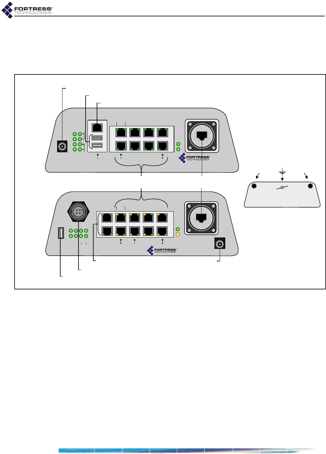
1.2.2 Hardware Versions
Fortress’s ES520 hardware platform includes two, distinct
hardware versions, distinguishable by their different front
panels.
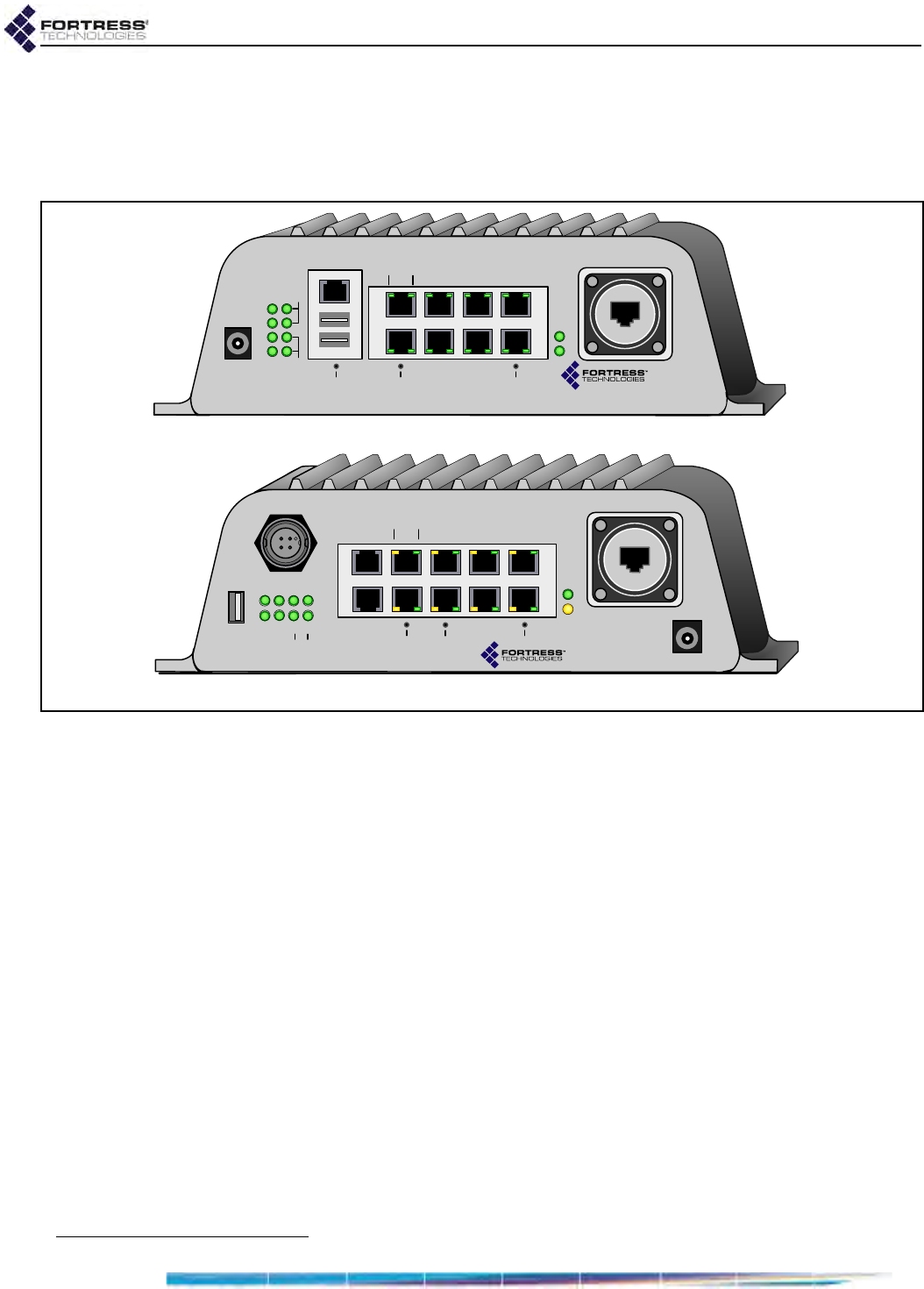
Figure 1.1. ES520 Hardware Versions
In particular, the version 2 chassis features a new weathertight,
locking, multi-range DC power input on the upper left of the
front panel and a second RJ-45 serial port. ES520 version 2
has one fewer USB ports than version 1 and is 1.5‘” inches
deeper.
Several front panel features were also repositioned between
the two versions, including status and radio LEDs, the 48V
barrel-style power inlet, the remaining USB port, and front-
panel switches.
1.2.3 Shipped Parts
Included in each ES520 Deployable Mesh Point shipment:
one ES520 version 1 or ES520 version 2 Mesh Point
one universal AC-to-48V DC power adapter
AC power cord
one PoE midspan adapter1
one RJ-45-to-DB9 serial port adapter
(for use with a straight-through Cat5 cable assembly)
ES520 version 2
ES520 version 1
+48V
DC
+48V
DC
Stat1
Stat2
Clr
Fail
Radio1
Radio2
Console
USB A/B
15
2
73
468
SW1 ResetSW2
Lnk/Act POE
Lnk/
Act
Pwr
WAN
ES520
48V
DC
St1 St2
Clr Fail 1
Radio
Console
USB
1
2
73
468
SW2 ResetSW1
Link/Act POE
Link/
Act
Pwr
WAN
Serial
2
ES520
12/24V 48V
+
-
1. Refer to Powering—for External Environments on page 6 for outdoor surge and safety requirements.

ES520 Hardware Guide: Overview
4
ES520 Weatherizing Kit, including:
one front-panel cover plate
one RJ-45 connector boot assembly (six pieces)
one antenna port cap
ES520 Mast-Mounting Kit, including:
one mast mounting bracket
two 4" long, fully threaded 1/4"x20 hex bolts
two 1/4" split lock washers
four 1/4"x20 wingnuts
software CD, including:
ES520 Mesh Point software package
Fortress and standard SNMP MIBs
RADIUS dictionary file with Fortress Vendor-Specific
Attributes for administrative authentication
ES520 Mesh Point user guides and latest release notes

ES520 Hardware Guide: Installation
5
Chapter 2
Installation
2.1 Preparation
Before designing your Mesh Point deployment, review the
powering and siting options and requirements described in
sections 2.1.2 through 2.1.5
Before proceeding with installation, review the safety
information in Section 2.1.1 below.
2.1.1 Safety Requirements
To prevent damage to the product and ensure your personal
safety, operate the Deployable Mesh Point only within the
operating specifications given in Section 4.1.2, and carefully
follow these guidelines:
WARNING: The
Mesh Point con-
tains a 3V (7 year) lithi-
um battery for time-
keeping purposes. It is
not intended to be oper-
ator- or user-replace-
able. To avoid risk of
personal injury (and
voiding of the Mesh
Point’s warranty), refer
all hardware servicing
to Fortress Technical
Support. There is a risk of
explosion if the battery is
replaced by an incorrect
type. Dispose of used
batteries according to
the new battery disposal
instructions.
General: This equipment must be installed by qualified
service personnel according to the applicable installation
codes. Do not locate the Mesh Point or antennas near
power lines or power circuits. When installing an external
antenna, take extreme care not to come into contact with
such circuits as they can cause serious injury or death.
Avoid metal ladders wherever possible. For proper
installation and grounding, refer to national and/or local
codes (WSNFPA 70 or, Canadian Electrical Code 54).
Indoor/Outdoor Siting: All interconnected equipment
connected to the indoor/outdoor Mesh Point must be
contained within the same building, including the
interconnected equipment's associated LAN connections.
In outdoor environments, the Deployable Mesh Point must
be mounted on a wall, pole, mast or tower using the
included mounting bracket, so that the antenna
connections are at the top and the WAN port is at the
bottom. When mounted outside, the Mesh Point’s Front
Panel Cover Plate (included) provides the necessary water
and dust resistance to environmentally protect the unit. In
addition, the three Front Panel Cover Plate thumbscrews
must be hand-tightened (taking care not to over-tighten) to
prevent the operator-access area (USB, Console, Ethernet

ES520 Hardware Guide: Installation
6
ports, and power inlets) from being exposed. The Mesh
Point should not be used outside a home, school, or other
public area where the general population has access to it.
FOR ES520 VERSION 1: When sited inside, the unit is
powered with 48VDC PoE or 48VDC external power.
FOR ES520 VERSION 2: When sited inside, the unit is
powered with 48VDC PoE, 48VDC external, or 7-30V (12/
24) power. Do not exceed 30V on the 7-30V (12/24) power
input or the unit can be damaged.
The included front-panel cover plate is not required for
indoor installations of either hardware version.
Ambient Temperature:
FOR ES520 VERSION 1: The temperature of the
environment in which the Mesh Point operates should not
exceed the maximum (122º F/50º C or drop below the
minimum (14º F/-10º C) operating temperatures.
FOR ES520 VERSION 2: The temperature of the
environment in which the Mesh Point operates should not
exceed the maximum (131º F/55º C) or drop below the
minimum (14º F/-10º C) operating temperatures.
Circuit Overloading: Both ES520 version Mesh Points
include an internal 48V resettable fuse. PoE powered ports
are protected with additional 48V resettable fuses.
FOR ES520 VERSION 2: The Mesh Point includes internal
resettable fuse on its 7-30V (12/24) power input. Do not
exceed 30V on the 7-30V (12/24) power input or the unit
can be damaged.
Powering—for External Environments:
FOR ES520 VERSION 1: To meet UL outdoor surge and
safety requirements, the Mesh Point must be powered with
the included 48V power supply through the included PoE
midspan adapter (or equivalent).
WARNING:
To
avoid the risk of
severe electrical shock,
never remove the cover,
an exterior panel, or any
other part of the Mesh
Points’s chassis. There
are no user-serviceable
parts inside. Refer all
hardware servicing to
Fortress Technical Sup-
port.
FOR ES520 VERSION 2: To meet UL outdoor surge and
safety requirements, the Mesh Point must be powered with
1) the included 48V power supply through the included PoE
midspan adapter (or equivalent), 2) a surge- and safety-
isolated AC/DC power supply to the 4-pin connector, or
3) a DC battery to the 4-pin connection.
The WAN port of both ES520 versions is lightning protected
at the Mesh Point end. It is recommended that additional
WAN port lightning protection be provided to protect
customer premises and equipment.
Powering—for Internal Environments:
FOR ES520 VERSION 1: The Mesh Point can be 1) direct
powered by the universal AC-to-48V DC (70 Watt) power
adapter, 2) PoE powered over the WAN port with the
included POE adapter (or equivalent), or 3) PoE powered
from a remote 802.11af (13 Watt) PoE midspan source.

ES520 Hardware Guide: Installation
7
FOR ES520 VERSION 2: The Mesh Point can be 1) direct
powered by the universal AC-to-48V DC (70 Watt) power
adapter, 2) PoE powered over the WAN port with the
included POE midspan adapter (or equivalent), 3) PoE
powered from an 802.11af PSE, or 4) externally powered
from a 7-30V (12/24) power source. Do not exceed 30V on
the 7-30V (12/24) power input or the unit can be damaged.
The AC to 48V power adapter included with both hardware
versions has reinforced isolation to meet the endspan
requirements of 802.11af, Power Sourcing Equipment.
Lightning/Electrostatic Protection: The Mesh Point’s
antenna ports conform to IEC1000-4-5 10 KV 8/20us
waveform. The WAN port conforms to IEC-61000-4-2 8 KV
waveform with 58 V additional transient protection.
WARNING: If the
Mesh Point con-
nects to outside-mount-
ed antennas, failure to
provide a low resistive
earth ground can result
in migration of voltage
from lightning or line
surges onto the premis-
es wiring, which can
cause electric shock
and/or fire within the
building or structure.
Grounding: The Mesh Point features a rear panel
grounding stud which must be connected to protective
earth ground via a 20 gauge (minimum) cable, before any
other physical connection is made.
The antenna/cable distribution system should be grounded
(earthed) in accordance with ANSI/NFPA 70, the National
Electrical Code (NEC), in particular, Section 820.93,
Grounding of Outer Conductive Shield of a Coaxial Cable.
The antenna mast and Deployable Mesh Point, when used
outside, should be grounding per Article 810 of the NEC; of
particular note is the requirement that the grounding
conductor not be less than 10 AWG(Cu).
Waterproofing: The Mesh Point has a UL (NEMA) 3/3S/4
raintight rating. The Front-panel Cover Plate of the ES520
Weatherizing Kit includes a “Raintight” label. The Mesh
Point is water resistant when the Weatherizing Kit (cover
plate, WAN-port RJ-45 connector boot assembly, and
antenna cap—included) is properly installed.
Cabling: Cables must be installed in accordance with NEC
Article 725 and 800, and all requirements must be met in
relation to clearances with power lines and lighting
conductors. All cabling must be category 5e per TIA/EIA-
568-B.2.
Radio Frequency: The Mesh Point’s internal radios
conform to the FCC’s safety standard for human exposure
to RF electromagnetic energy, provided that you follow
these guidelines:
Do not touch or move the antennas while the unit is
transmitting or receiving.
To safeguard Mesh Point transmitting circuitry, relocate
the Mesh Point and its antennas only when the Mesh
Point is powered off.
When the Mesh Point is transmitting, do not hold it so
that the antenna is very close to or touching any
exposed parts of the body, especially the face or eyes.
ES520 Hardware Guide: Installation
8
NOTE: The ES520
complies with UL
60950-1 safety specifica-
tions. It has a UL (NE-
MA) 3/3S/4 (and
IEC60529) environmen-
tal rating. The Front-
panel Cover Plate of the
ES520 Weatherizing Kit
includes a “Raintight”
label.
Antennas must be installed to provide a separation of at
least 20 cm (7.9") from all persons and any co-located
antenna or transmitter.
Regarding use in specific environments:
•
Do not
operate near unshielded blasting caps or in an
explosive environment.
•
Limit use in a hazardous
location to the constraints imposed by the location’s
safety director.
•
Abide by the rules of the Federal
Aviation Administration for the use of wireless devices
on airplanes.
•
Restrict the use of wireless devices in
hospitals to the limits set forth by each hospital.
2.1.2 Outdoor Siting Requirements and Restrictions
Mesh Points intended to be used out-of-doors must be fully
weatherized and mast-mounted (as described in sections 2.3
and 2.4), with significant follow-on effects:
CAUTION: Review
the primary docu-
mentation in chapters 3
and 4 of the Mesh Point
functions you intend to
employ in advance of
determining your hard-
ware setup. Some hard-
ware features are
configurable; some soft-
ware functions have
specific hardware limi-
tations/requirements.
At minimum, essential connectivity and security parameters
should preconfigured and tested on an outdoor Mesh Point
in advance of its deployment in the field.
The LAN switch ports on an outdoor Mesh Point are
blocked by the required front-panel cover plate. The only
available network connections on an outdoor Mesh Point
are its front-panel WAN port and radio interfaces.
The Mesh Point’s optional PSE function is exclusive to the
Mesh Point’s LAN switch ports. It has no application in an
outdoor Mesh Point.
As described in Section 1.1, on ES520 version 1 hardware,
outdoor Mesh Points must be powered via their WAN port
using a compatible Power over Ethernet (PoE) source. On
ES520 version 2 hardware, outdoor Mesh Points can be
powered through their WAN ports or through their
weatherized, 4-pin, multi-range DC power inputs.
None of the above functional restrictions apply to Mesh Points
installed indoors.
2.1.3 Hardware Version Powering Options
The two ES520 hardware versions (Section 1.2.2) are both
equipped with a barrel-style 48V DC power input intended
exclusively for indoor use.
NOTE: ES520 pow-
er inputs are not
intended to provide re-
dundancy in either
hardware version.
Both hardware versions can optionally be powered through
their WAN ports by a remote Power over Ethernet (PoE)
midspan or endspan device. The WAN port PoE can be used to
power the Mesh Point indoors or, when the Mesh Point is fully
weatherized (Section 2.3), outdoors.
Included with both versions are one 70W universal AC-to-DC
power adapter module and one PoE midspan device.
The ES520 version 2 is additionally equipped with a
weathertight, 4-pin, multi-range DC input that can be used to

ES520 Hardware Guide: Installation
9
power an indoor Mesh Point or an outdoor, weatherized Mesh
Point.
2.1.3.1 ES520 Version 1
As described in Section 2.3, when an ES520 version 1 Mesh
Point is weatherized for outdoor installation, the only power
input available for use is the WAN port PoE input.
When the an ES520 version 1 Mesh Point is installed indoors,
you can connect either or both power inputs:
barrel-style 48V DC input directly connected to the AC-to-
DC (70 Watt) power adapter included with the Mesh Point
WAN port PoE input connected to the remote PoE midspan
adapter (or equivalent) included with the Mesh Point, or to
a 802.11af PoE endspan source
When you connect both sources, they provide a measure of
redundancy.
As the higher voltage of the two supplies, the barrel-style input
connected directly to the 70 Watt power adapter is primary,
backed up by the WAN port PoE supply. If the primary power
supply is lost, a PoE midspan device can take over without
interruption. A PoE endspan device may allow a lapse before
sensing that the Mesh Point is powered down and resupplying
it via the WAN port. When the 48V DC power input is again
receiving power, it will again become primary.
2.1.3.2 ES520 Version 2
Two sets of connections comprise the weathertight, 4-pin,
multi-range DC input: the left pair of pins is for 12/24V power
(7–30 range); the right pair of pins is for 48V power (36V–60V
range).
In order to use the 4-pin, multi-range DC input, you must obtain
a suitable mating cable-end socket connector and attach it
according to the pin-outs described in Section 4.3 to a cable
composed of 18 gauge (minimum) to 16 gauge (maximum)
wire.
7–30 Volt Powering
If you use the Mesh Point’s 4-pin multi-range DC input to
supply 7-30V (12V/24V) power to the Mesh Point, it will be the
Mesh Point’s sole source of power. All 48V DC power inputs
are disabled.
Purchase a weathertight mating connector or molded cable
end assembly from Fortress Technologies or Switchcraft®
(Mini-Con-X® series part # 382-4SG-3DC).
ES520 Hardware Guide: Installation
10
48 Volt Powering
CAUTION: When
an ES520 version 2
Mesh Point is indoors
and powered by a 48V
power supply, that sup-
ply must be isolated
from its AC power
mains and chassis
ground to adhere to
802.3af PSE Safety stan-
dards.
If you use the Mesh Point’s weathertight 4-pin DC input to
supply 48V power to a weatherized, ES520 version 2 Mesh
Point installed outside, you can use WAN port PoE as a backup
supply.
As the higher voltage of two power supplies in this scenario,
the 4-pin 48V DC power input is primary. If it loses power, a
PoE midspan device can take over without interruption. A PoE
endspan device may allow a lapse before sensing that the
Mesh Point is powered down and resupplying it via the WAN
port. When the 4-pin, 48V DC power input is again receiving
power, it will again become primary.
NOTE: All power
inputs should be
applied before the Mesh
Point is put into regular
operation. When pow-
ered by endspan PoE,
particularly, plugging in
a redundant 48V power
source will cause the
Mesh Point to reboot.
In an indoor installation of an ES520 version 2 Mesh Point
using 48V power, you can connect any two or all three power
inputs to provide redundancy. If both the 48V barrel-style and
the 48V 4-pin DC power inputs are connected, the higher
voltage power source will serve as the primary supply. If the
two sources are supplying identical voltage, the two inputs
share the supply.
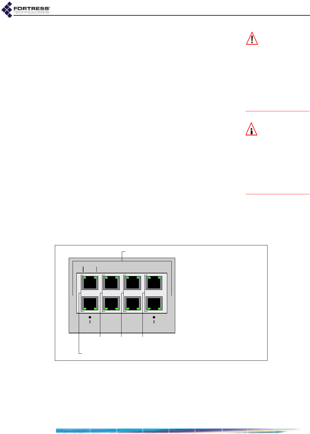
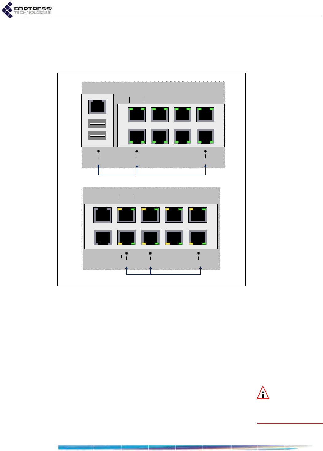
2.1.4 Internal LAN Switch PoE PSE Function
The Mesh Point’s Power over Internet Power Sourcing
Equipment (PoE PSE) function can supply up to 36 Watts of
power overall, with an additional maximum limit—per interface
pair—of 16 Watts. The LAN switch’s eight Ethernet ports are
paired in sequence: 1 and 2, 3 and 4, 5 and 6, 7 and 8, as they
are vertically aligned on the Mesh Point’s front panel.
Figure 2.1. Internal LAN Switch PSE Maximums
15
2
73
468
ResetSW2
POELnk/Act
16W max. PoE per vertically stacked pair
16W
max. 16W
max. 16W
max.
36W max. PoE overall
PD Requirements:
PoE Class 0/3= 15.4 W
PoE Class 2 = 7 W
PoE Class 1 = 4 W

ES520 Hardware Guide: Installation
11
NOTE: In order to
supply PoE, the
Mesh Point must be lo-
cally powered by either
the AC-to-DC adapter
or 48V 4-pin input. Both
48V power supplies are
highly isolated to meet
PSE standards and will
provide up to 36W of to-
tal PSE power.
The IEEE 802.3af standard classifies PoE powered devices
(PDs) according to the amount of power allocated for them:
Class 3 PDs are allocated 15.4 W.
Class 2 PDs are allocated 7 W.
Class 1 PDs are allocated 4 W.
Class 0 is a catch-all for devices that cannot be otherwise
classified; PDs in this class are allocated 15.4 W.
The Mesh Point supports a small set of legacy devices that do
not comply with the 802.3af classification standard:
Cisco® AP 1100 WAP
Cisco AP 1200 WAP
Cisco AP 350 WAP
Cisco 7910 IP Phone
Cisco 7940 IP Phone
Cisco 7960 IP Phone
Nortel® i2002 IP Phone Phase 1 sets (with Power-Splitter)
Nortel i2004 IP Phone Phase 1 sets (with Power-Splitter)
These devices fall into the 802.3af catch-all Class 0 and are
allocated 15.4 W regardless of their actual power
requirements.
Table 2.1 shows the total number of PDs of various classes
and combinations of classes that the Mesh Point can support
overall.
When a PD is plugged into a PoE-enabled LAN port, it will be
powered up only if there is sufficient overall power available to
allocate to a device of its class. If the Mesh Point would exceed
its maximum of 36 Watts by allocating the amount of power
Table 2.1. Maximum Connected PDs by PoE Class
802.3af Class Total Power
Allocated
0 & 3 2 1
20 1 36 W
12 1 34 W
11 3 35 W
10 5 36 W
05 0 35 W
04 2 36 W
03 3 33 W
02 5 34 W
01 7 35 W
00 8 32 W

ES520 Hardware Guide: Installation
12
required by the new PD’s Class (as described above), the new
PD will not be powered up.
NOTE: If one port
in a PSE pair is
supplying power to a
PoE Class 3 or Class 0
device, you can ensure
that their shared fuse
will not be overloaded
by an attempt to supply
power to another PD by
leaving PSE Disabled
(the default) on the sec-
ond port in the pair.
In addition to the overall maximums, keep in mind that the
distribution of PDs across LAN switch interfaces must not
exceed the 16-Watt limit per vertically stacked port-pair
(described above). A given pair of ports can therefore supply
sufficient power to only one Class 3 or Class 0 PD or to two
Class 2 and/or Class 1 PDs.
Each associated (vertically aligned) pair of PoE LAN switch
interfaces shares a self-recovering fuse. If you exceed the 16-
Watt port-pair maximum without exceeding the overall
maximum, the breaker will trip, temporarily powering both ports
off. The circuit resets automatically, re-enabling both ports. If
the PSE overload has not been corrected, however, the circuit
will break again. The process will recycle until one of the PDs
on the pair is unplugged.
In order for the Mesh Point to supply PoE to PDs through a
LAN switch port, you must enable PSE on the port, as
described in the Software GUI Guide.
ES520 Hardware Guide: Installation
13
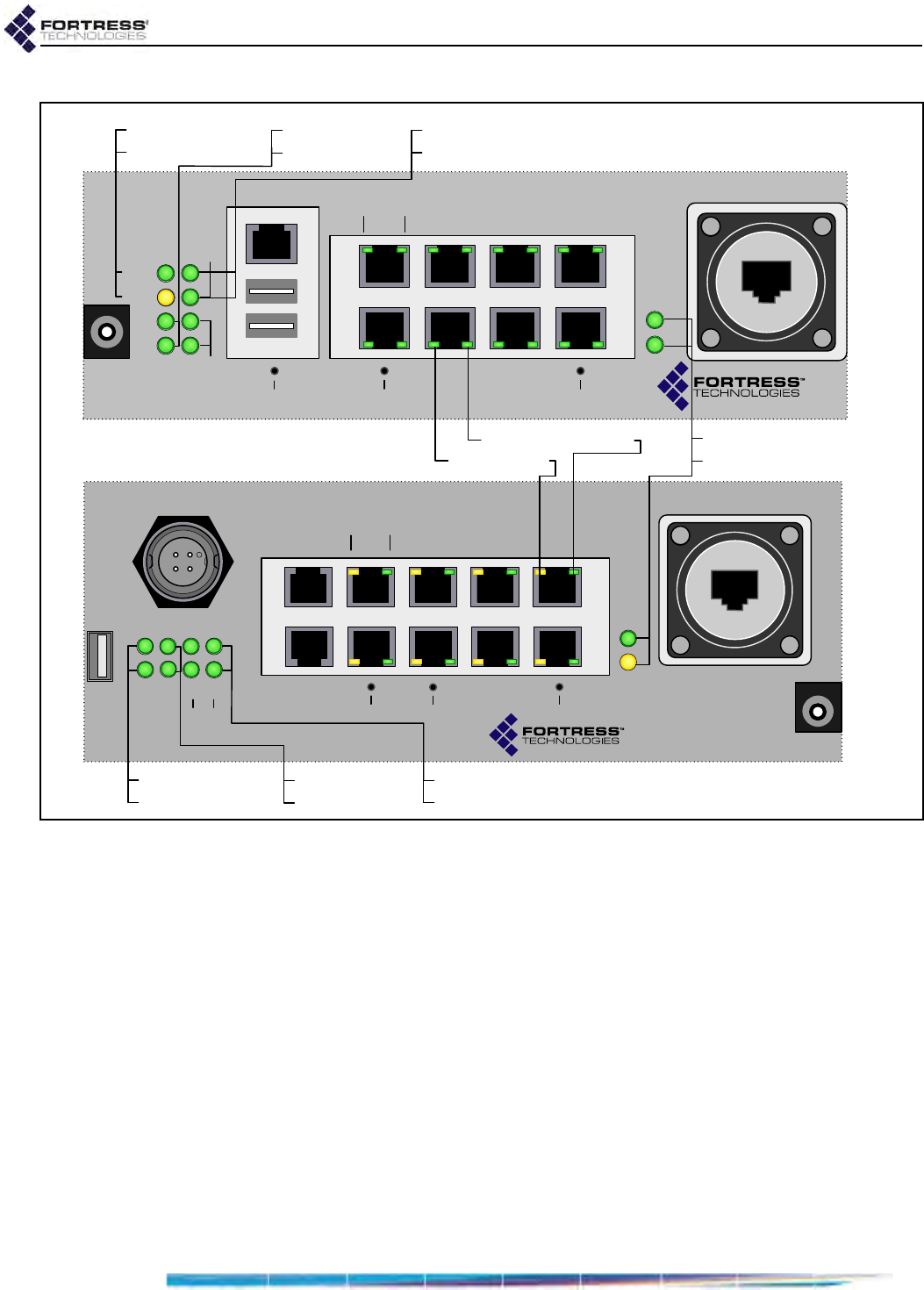
2.1.5 Port Locations
The ES520 Mesh Point’s dual antenna ports and grounding
stud are located on the back panel. The rest of the ES520’s
ports are located on the front panel, shown below.
Figure 2.2. Fortress ES520 Mesh Point Port Locations
2.1.6 Network Interfaces
The ES520 Mesh Point's Ethernet WAN port and eight LAN
switch ports, numbered 1–8, comprise its wired network
connections. Its two internal radios can be configured with up
to four independent wireless interfaces, or Basic Service Sets
(BSSs), each. You can configure the Mesh Point's network
interfaces to meet various deployment and security
requirements (see the Software GUI Guide).
2.2 Connecting the ES520
The ES520 can be connected temporarily for preconfiguration
of the Mesh Point software and then permanently for
deployment.
+48V
DC
+48V
DC
Stat1
Stat2
Clr
Fail
Radio2
Radio1
Console
USB A/B
15
2
73
468
SW1 ResetSW2
Lnk/Act POE
Lnk/
Act
Pwr
WAN
ES520
DC power input
WAN port, default encrypted
PD/PoE interface
RJ-45 serial port
RJ-45 Ethernet ports, default clear
PSE/PoE interfaces
USB port
48V
DC
St1 St2
Clr Fail 1
Radio
Console
USB
1
2
73
468
SW2 ResetSW1
Link/Act POE
Link/
Act
Pwr
WAN
Serial
2
12/24V 48V
ES520
5
RJ-45 serial ports
weathertight multi-mode DC power input
USB ports
DC power input
ES520
version 2
ES520
version 1
rear-panels:
two N-type antenna ports;
one grounding stud
ANT1 ANT2
+
-
ES520 Hardware Guide: Installation
14
2.2.1 Connections for Preconfiguration
Mesh Point software should be configured in advance of
deployment. This section provides instructions for temporarily
connecting the ES520 Mesh Point for preconfiguration.
1Position the Mesh Point so that it operates only within its
safe temperature range (14º–122º F/–10º–50º C for ES520
version 1; 14º–131º F/–10º–55º C for ES520 version 2).
2Connect the Mesh Point to an external power source: refer
to Section 1.1, This Document.
3Connect one of the Mesh Point’s LAN switch ports (1–8 on
the front panel) to a computer or switch on the wired LAN.
To complete the configuration, refer to the Software GUI Guide
or Software CLI Guide for instructions on Logging On,
Licensing, and Configuring the Mesh Point software.
2.2.2 Connections for Deployment WARNING: To
comply with FCC
regulations, antennas
must be professionally
installed and the install-
er is responsible for en-
suring compliance with
FCC limits.
Review the Radio Frequency Safety Requirements (Section
2.1.1) before installing or operating Mesh Point radios.
1If the Mesh Point or its antenna(s) or any network
component to which the Mesh Point will be physically
connected will be located outside, connect the rear-panel
grounding stud to protective earth ground with a 20 gauge
(minimum) cable.
2If your deployment uses Radio 1, connect a standard 2.4
GHz- or 5 GHz-capable antenna with an N-type male
connector to antenna port 1 (ANT1).
CAUTION: The
FCC requires co-
located radio antennas
to be at least 7.9" apart.
The Mesh Point’s anten-
na connectors are only
5" apart. Avoid directly
mounting two antennas to
the Mesh Point’s rear-pan-
el connectors.
If the Mesh Point (or antenna) will be located outside, the
antenna must be waterproof.
3If your deployment uses Radio 2, connect an antenna cable
with a N-type male connector between antenna port 2
(ANT2) and a high-gain omnidirectional or directional
antenna.
If the Mesh Point (or antenna) will be located outside, the
antenna and cable must be waterproof.
4If the Mesh Point is sited indoors where it does not need to
be weatherized and your deployment will use one more of
the LAN switch ports (labeled 1-8), connect them with
standard Cat5 Ethernet cables.
NOTE: Third par-
ty antennas are
subject to local regulato-
ry requirements. For
outdoor installations,
they must be water-
proof.
By default, all LAN switch ports are in the clear (Fortress
Security-disabled), but you can reconfigure them, per port,
to provide encrypted or clear network interfaces (refer to
the Software GUI Guide).
If you are using the Mesh Point’s PSE function, refer to
Section 2.1.4 for guidance on the number of devices you can
connect. If you are not using the Mesh Point’s 802.3af
power sourcing equipment (PSE) function to supply Power

ES520 Hardware Guide: Installation
15
over Ethernet (PoE) to devices connected to its LAN
switch, you can connect up to eight Ethernet devices. If
your deployment uses the WAN port for data, connect it to
the appropriate network device.
NOTE: Configure
whether a given
Ethernet interface is in
the clear or encrypted
(Fortress Security-en-
abled) on Configure ->
Ethernet Settings.
5If your deployment uses the WAN port for data, connect it to
the appropriate network device.
To plug in the RJ-45 connector with the boot assembly
installed: orient the connector correctly with the WAN port,
and then twist the outer ring of the connector boot
clockwise until the channels in the ring align with the
locking studs on the Mesh Point’s WAN port casing.
Continue twisting the boot’s outer ring clockwise until the
locking channels are fully engaged and the boot is flush
with the port casing. A distinct click in the final turn of the
boot’s outer ring indicates that connector and boot are
securely plugged into the Mesh Point. (Installing the
connector boot assembly is covered in Section 2.3.)
By default, the WAN port is encrypted (Fortress Security-
enabled), but you can configure it to provide a clear or
encrypted network interface (refer to the Software GUI
Guide).
6Connect the Mesh Point (or verify its connection to) to the
power source(s) it will use: refer to Section 1.1, This
Document.
7Verify that link/activity and power LEDs illuminate for all
connected ports and that the upper radio LED illuminates
for the enabled radio(s).
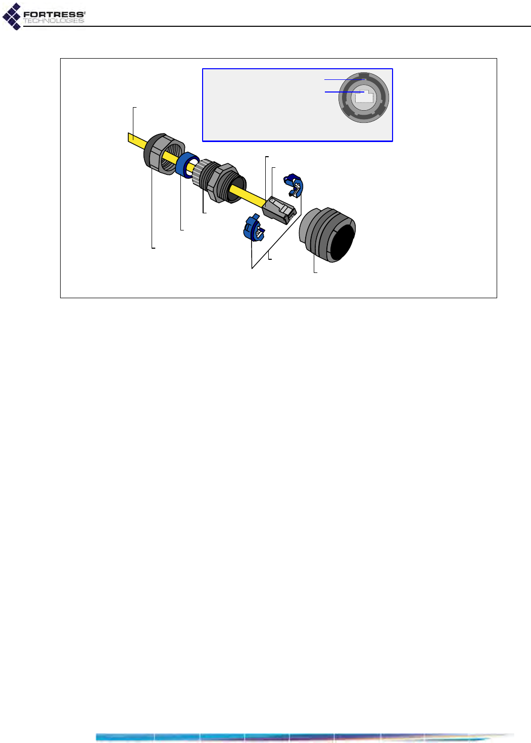
2.3 Weatherizing the ES520 for Outdoor
Installation
CAUTION:
Do not
assemble the con-
nector boot without first
referring to these in-
structions. Several as-
sembly steps are
irreversible.
Incorrectly
assembled connector
boots are unusable
, and
cannot be disassembled.
The weathertight, locking 4-pin DC power input (Switchcraft®
Mini-Con-X® series) is present only in the ES520 version 2
Mesh Point. It is weathertight with or without the protective cap
attached to the connector when it ships.
Obtain a weathertight mating connector or molded cable end
assembly from Fortress Technologies or from Switchcraft.
All front-panel ports must be disconnected before you can
install the Weatherizing Kit.
ES520 Hardware Guide: Installation
16
Figure 2.3. Installing the RJ-45 Connector Boot Assembly
1Install the RJ-45 connector boot assembly on the end of the
cable that you will be plugging into the Fortress Mesh
Point’s WAN port, as shown in Figure 2.3:
If the RJ-45 connector is equipped with a molded
plastic boot, remove it from the connector. (Some
Ethernet cable connectors have a molded plastic outer
casing that is not designed for removal. This style of
connector is incompatible with the connector boot.)
Slide the compression nut, with the threaded opening
facing toward the connector, over the connector and
onto the cable.
Slide the compression bushing over the connector and
onto the cable.
Slide the threaded coupler, with the flanged end facing
toward the compression nut and bushing, over the
connector and onto the cable.
With the smooth-side prongs on the two halves of the
connector collar facing out and aligned with the RJ-45
connector’s locking tab, fit the collar around the
connector so that the connector’s locking tab is
compressed (the contact end of the connector extends
approximately 1/2" from the collar). Fit the outer tabs on
one half of the connector collar into the slots of the
other, and squeeze the two halves of the connector
collar together until they snap into place.
compression nut
compression
bushing
threaded
coupler
connector
collar connector
boot
RJ-45 connector
RJ-45 connector locking tab
Ethernet cable
Boot/Connector Alignment
locking tab (on RJ-45 connector)
primary key tab (on boot inner ring)
Connector Boot Assembly
ES520 Hardware Guide: Installation
17
CAUTION: There
are four different
possible alignments be-
tween the RJ-45 connec-
tor and the connector
boot. If the boot and
connector are not in the
correct alignment, the
RJ-45 connector will not
plug into the Mesh
Point’s WAN port.
Align the primary key tab on the inner ring of the
connector boot with the cable connector’s locking tab.
Maintaining this alignment, fit the RJ-45 connector-
collar assembly into the boot through the boot’s
threaded end and snap the collar tabs into the boot
slots. Screw the connector boot securely onto the
threaded coupler.
Fit the compression bushing into the flanged end of the
threaded connector, and fit the compression nut over
the flanges. Screw the compression nut securely onto
the threaded connector until the bushing is compressed
around the cable to provide a water seal.
Step 5 of Section 2.2.2 describes plugging the
connector/boot into the Mesh Point’s WAN port.
WARNING: To
avoid the risk of
severe electrical shock,
do not remove the cover
plate while the Fortress
Mesh Point is out of
doors.
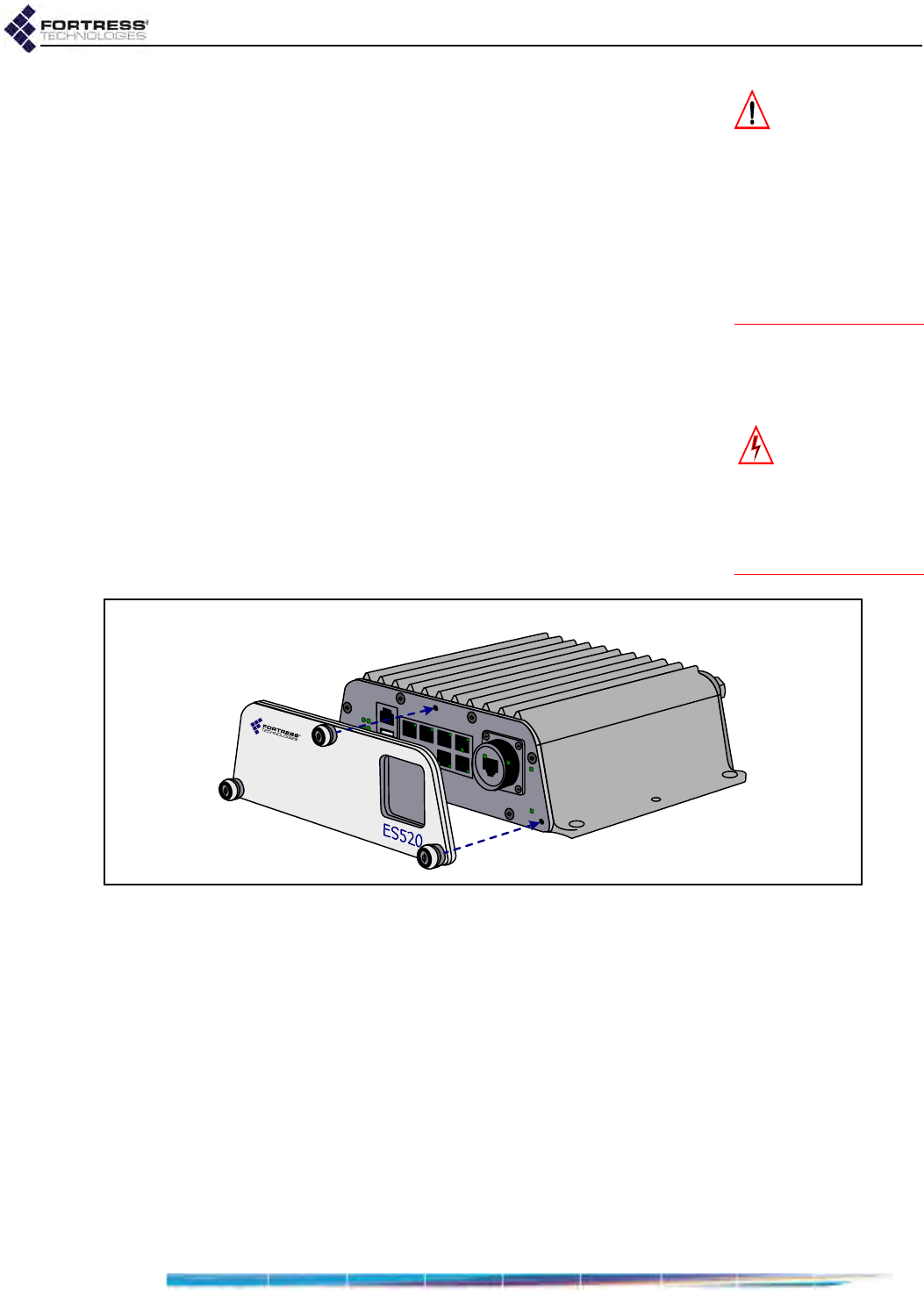
2Attach the cover plate to the Mesh Point’s front panel with
the plate’s three captive screws, as shown in Figure 2.4.
The front-panel cover plate for ES520 version 2 Mesh
Points features an additional opening for the weatherized,
locking, multi-range DC power input.
Figure 2.4. Attaching the Front-panel Cover Plate for an ES520 version 1
3If only one antenna will be attached to the Mesh Point,
screw the antenna port cap onto the unused antenna port.
2.4 Mast Mounting the ES520
The Mast-Mounting Kit accommodates masts from 1.5" to 3" in
diameter.
1Fit the two hex bolts through the center mounting holes in
the lip extensions of the Mesh Point’s underside, top to
bottom.
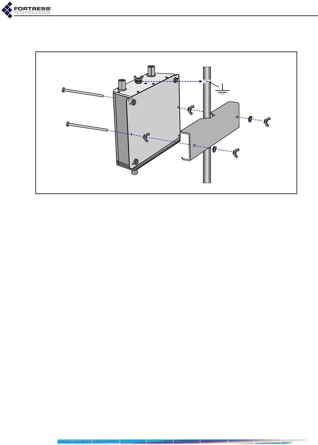
ES520 Hardware Guide: Installation
18
2Fix each bolt to the Mesh Point chassis with a wing nut,
tightened securely to the underside of the Mesh Point.
Figure 2.5. Attaching the Mast-Mounting Bracket and Grounding Stud
3Position the Mesh Point at the desired position on the mast,
with the Mesh Point’s underside facing toward the mast and
the front panel facing down, as shown in Figure 2.5.
4Sandwiching the mast between the underside of the Mesh
Point and the mounting bracket, fit the mast into the
toothed cut-outs in the mounting bracket and the bolt shafts
extending from the Mesh Point through the holes in the
bracket.
5Place a split lock washer and then a wing nut on each of
the bolts ends, and tighten the nuts until the washers are
flattened against the mounting bracket.
ES520 Hardware Guide: LEDs and Recessed Button Operation
19
Chapter 3
LEDs and Recessed Button
Operation
3.1 Front-Panel Indicators
NOTE: There are
no LED indica-
tions in a Mesh Point in
blackout mode (refer to
Section 3.2.1.2).
The Fortress ES520 Mesh Point’s front panel features five
system LEDs (Stat1, Stat2, Clr, Fail and Pwr), four radio LEDs
(two for each of Radio1 and Radio2), as well as a pair of link/
activity (Lnk/Act) and power-over-Ethernet (POE) LEDs for each
of the Mesh Point’s nine Ethernet ports.
3.1.1 Status, Cleartext and Failure LEDs
color behavior
Stat1 Stat2 Clr Fail Pwr
system status cleartext failure system power/
WAN PoE
green
solid normal
operation
n/a n/a n/a
powered on
slow flash booting -
fast flash --
off - powered off
ES520 Hardware Guide: LEDs and Recessed Button Operation
20
Figure 3.1. Fortress ES520 Mesh Point LED Indicators
Stat1
can exhibit:
solid green - The Mesh Point is operating normally.
slow green flash - The Mesh Point is booting.
Stat2 is reserved for the Mesh Point’s Automatic Configuration
distribution function (refer to the Auto Config Software Guide).
Clr is reserved for a future function on the Mesh Point.
Fail is reserved for a future function on the Mesh Point.
Pwr
can exhibit:
solid green - The Mesh Point is powered on, either through
the +48V DC adapter inlet or the WAN port’s PoE
connection.
off - The Mesh Point is powered off.
System Power LED
Activity LED Radio 2
WDS LED Radio 2
+48V
DC
Stat1
Stat2
Clr
Fail
Radio2
Radio1
Console
USB A/B
15
2
73
468
SW1 ResetSW2
Lnk/Act POE
Lnk/
Act
Pwr
WAN
ES
Link/Activity LED
Power-over-Ethernet LED Link/Activity LED for WAN port
2nd Status LED
System Status LED
Fail LED
Cleartext LED
48V
DC
St1 St2
Clr Fail 1
Radio
Console
USB
1
2
73
468
SW2 ResetSW1
Link/Act POE
Link/
Act
Pwr
WAN
Serial
2
12/24V 48V
ES520
5
Activity LED Radio 2
WDS LED Radio 2
Cleartext LED
System Status LED
Fail LED
2nd Status LED
ES520 version 1
ES520 version 2
+
-

ES520 Hardware Guide: LEDs and Recessed Button Operation
21
3.1.2 Radio LEDs
The Mesh Point’s internal radios are each associated with a
pair of front-panel LEDs, labeled Radio1 and Radio2. Radio
LEDs are arranged one above the other. Each radio then has
an associated upper and lower LED.
When the Mesh Point’s Received Signal Strength Indicator
(RSSI) feature (refer to the Software GUI Guide) is Disabled (the
default), Radio1 and Radio2 LEDs behave as shown below.
The upper LED can exhibit:
solid green - The associated radio is on.
intermittent green flash - The radio is passing traffic.
off - The associated radio is off or RF Kill is activated.
The lower radio LEDs are reserved for future functions on the
Mesh Point.
3.1.3 Port and Power LEDs
The Mesh Point’s front-panel Ethernet ports, including the WAN
and internal LAN switch ports, numbered 1 through 8 on the
front panel, are equipped with a link/activity LED. LAN switch
ports also feature a Power over Ethernet (PoE) status LED.
NOTE: The LEDs
for the Mesh
Point’s Console port are
not operational.
The Mesh Point’s PSE function enables it to supply PoE to
Powered Devices (PDs) connected to its internal LAN switch
ports. The PoE status LED applies only when you have
connected PDs to the Mesh Point’s internal LAN switch
(Section 2.1.4) and only to ports on which the PSE (Power
Sourcing Equipment) function has been enabled (see the
Software GUI Guide).
Lnk/Act
can exhibit:
solid green - A link has been established for the port.
intermittent green flash - Traffic is passing on the link.
POE
can exhibit:
solid green - Power on: the port is supplying power to a
connected PD.
ES520 Hardware Guide: LEDs and Recessed Button Operation
22
3.2 Front-Panel Operation
The ES520 Mesh Point front panel is equipped with three,
recessed buttons: two switches (labeled SW1 and SW2) and a
Reset button.
Figure 3.2. ES520 Front-Panel Buttons
3.2.1 Mode Selection from the Front Panel
The front-panel switches can be used to toggle RF (Radio
Frequency) Kill mode on and off, as well as to turn the Mesh
Point’s front-panel LEDs off and on (Blackout Mode, Enabled/
Disabled).
Each of these Mesh Point settings has only two possible
values. Configuring them through the front-panel switches
toggles the setting from its current value to the alternate value.
3.2.1.1 Togging the RF Kill Mode setting
NOTE: You can
also change the RF
Kill mode setting in the
Mesh Point GUI (see the
Software GUI Guide).
The SW1 button toggles the Mesh Point’s RF Kill mode to turn
both internal radios on and off.
The default RF Kill mode setting is Disabled, in which state the
Mesh Point receives and transmits radio frequency signals
normally.
Console 1
2
73
468
SW2 ResetSW1
Link/Act POE
Serial
5
recessed buttons on the ES520 version 2
recessed buttons on the ES520 version 1
Console
USB A/B
15
2
73
468
SW1 ResetSW2
Lnk/Act POE

ES520 Hardware Guide: LEDs and Recessed Button Operation
23
If the RF Kill mode is Disabled, the procedure below will enable
it (turn off the radios). If the Mesh Point is already in Kill All RF
mode, the procedure will disable it (turn on the internal radios):
1Depress and hold SW1 for five seconds.
2Release SW1.
The new setting persists over reboots and upgrades, just as
when changed through the Mesh Point GUI.
3.2.1.2 Toggling the Blackout Mode setting
The default blackout mode setting is Disabled, in which state
the Mesh Point’s front-panel LEDs illuminate to indicate various
conditions on the Fortress Mesh Point. (Front-panel LED
behaviors and their associated meanings are covered in
Section 3.1.)
NOTE: You can
also change the
Blackout Mode setting in
the Mesh Point GUI (see
the Software GUI Guide)
or in the Mesh Point CLI
(see the Software CLI
Guide).
Enabling blackout mode turns all front-panel LEDs off.
If blackout mode is Disabled, the procedure below will enable it
(turn off the front-panel LEDs). If the Mesh Point is already in
blackout mode, the procedure will disable it (turn the front-
panel LEDs back on)
1Depress and hold SW2 for five seconds.
If you are enabling blackout mode, the LEDs all go off, once
you have held the switch long enough. If you are disabling
blackout mode, hold the switch until the LEDs turn on.
2Release SW2.
After you have saved the change, Mesh Point LEDs will either
resume their normal operation (Blackout Mode: Disabled), or go
completely dark (Blackout Mode: Enabled), according to the new
setting.
NOTE: There are
no LED indica-
tions in a Mesh Point in
blackout mode (refer to
Section 3.2.1.2).
3.2.2 Rebooting the Mesh Point from the Front Panel
To reboot the Fortress Mesh Point from the front-panel:
1Press the Reset button. All Ethernet port LEDs light solid
green.
2Release the button.
After the Mesh Point reboots the Stat1 LED will again light solid
green.
3.2.3 Restoring Defaults from the Front Panel
To restore the Mesh Point’s configuration settings to their
factory-default values:
1With the Mesh Point powered on, simultaneously press and
hold SW1 and SW2 until the Stat1 LED begins to flash
(about 10 seconds).
2Release both switches.
After you have successfully initiated the restore operation, the
Mesh Point will reboot automatically.


ES520 Hardware Guide: Specifications
25
Chapter 4
Specifications
4.1 Hardware Specifications
4.1.1 Physical Specifications
hardware
version: ES520 version 1 ES520 version 2
form factor: compact, rugged chassis compact, rugged chassis
dimensions: 2.3" H x 8.75" W x 6.6" D
(5.8 cm×22.2cm×16.8cm)
2.3" H x 8.75" W x 8.1" D
(5.8 cm×22.2cm×20.57cm)
weight: 3.5 lbs. (1.6 kg), approximate 4.88 lbs. (2.21 kg) approximate
connections:
nine RJ-45 10/100 Mbps Ethernet ports
one RJ-45 serial port
two USB ports
two N-type radio antenna ports (female):
ANT1 (configured as 802.11a/b/g dual-band port)
ANT2 (configured as high-gain 802.11a port, 5.7–5.8 GHz)
one 48V DC power input port
nine RJ-45 10/100 Mbps Ethernet ports
two RJ-45 serial ports
one USB port
two N-type radio antenna ports (female):
ANT1 (configured as 802.11a/b/g dual-band port)
ANT2 (configured as high-gain 802.11a port, 5.7–5.8 GHz)
one 48V DC power input port
one weathertight multi-range DC power input port
radios: Radio1: 802.11a/b/g dual-band 5GHz/2.4GHz radio
Radio2: 802.11a 5GHz (standard) or 802.11 4.4GHz (mili-
tary)
Radio1: 802.11a/b/g dual-band 5GHz/2.4GHz radio
Radio2: 802.11a 5GHz (standard) or 802.11 4.4GHz (mili-
tary)
power
supply: external +48V AC-to-DC adapter or
WAN port power over Ethernet (PoE)
external +48V AC-to-DC adapter or
WAN port power over Ethernet (PoE)
system
indicators:
eight front-panel system LEDs (G/Y):
Status1 (Stat1), Status 2 (Stat2),
Cleartext (Clr), Failure (Fail),
four front-panel radio LEDs (G/Y):
two LEDs for wireless Radio2
two LEDs for wireless Radio1
nine pairs integrated port link/activity & power LEDs
eight front-panel system LEDs (G/Y):
Status1 (Stat1), Status2 (Stat2),
Cleartext (Clr), Failure (Fail),
four front-panel radio LEDs (G/Y):
two LEDs for wireless Radio2
two LEDs for wireless Radio1
nine pairs integrated port link/activity & power LEDs

ES520 Hardware Guide: Specifications
26
4.1.2 Environmental Specifications
4.1.3 Compliance and Standards
The Fortress ES520 is certified by the Wi-Fi Alliance® for the
following standards:
hardware version: ES520 version 1 ES520 version 2
maximum AC draw:
70 Watts
with per-port PoE PSE enabled
13 Watts
without PSE enabled
70 Watts
with per-port PoE PSE enabled
13 Watts
without PSE enabled
maximum heat dissipation: 44.3 BTU/hr 44.3 BTU/hr
cooling: fanless heat sink chassis fanless heat sink chassis
operating temperature: 14º–122º F (-10º–50º C) 14º–131º F (-10º–55º C)
operating relative humidity
(non-condensing): 5%–95% 5%–95%
storage temperature: -4º–158º F (-20º–70º C) -4º–158º F (-20º–70º C)
hardware
version: ES520 version 1 ES520 version 2
safety: UL60950-1, IEC60529 (CB test),
UL (NEMA) 3/3S/4 “raintight”
UL60950-1 (pending), IEC60529 (pending),
UL (NEMA) 3/3S/4 “raintight”
emissions: CE, FCC Class A CE, FCC Class A
immunity: EN61000-3, EN61000-4 EN61000-3, EN61000-4
vibration: MIL-STD 810G 514 / SC-18 (pending)
IEC 60068-2-6: Test Fc: Vibration Sinusoidal
IEC 60068-2-27: Test Ea and guidance: Shock
IEC 60068-2-64: Test Fh: Vibration Random
IEC 60068-2-29: Test Eb and guidance: Bump
IEEE: 802.11a/b/g
security: WPA™, WPA2™—Personal and Enterprise
EAP types: EAP-TLS, EAP-TTLS/MSCHAPv2,
PEAPv0/EAP-MSCHAPv2, PEAPv1/EAP-GTC,
EAP-SIM
ES520 Hardware Guide: Specifications
27
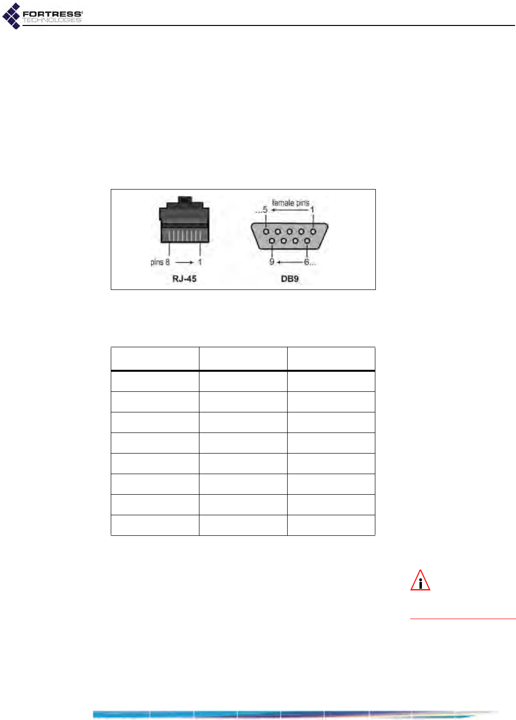
4.2 RJ-45-to-DB9 Console Port Adapter
An RJ-45-to-DB9 adapter (included with each Mesh Point) is
required in order to connect the Mesh Point’s Console port to a
DB9 terminal connection.
Figure 4.1 shows the pin numbers for the two connectors. With
the RJ-45 connector facing you and oriented with the tab
receptacle up, pins are numbered from right to left, as shown.
With the DB9 connector facing you and oriented with the wide
side up, pins are numbered from right to left, top to bottom.
Figure 4.1 RJ-45 and DB9 Pin Numbering
Table 4.1 shows the adapter pin-outs.
4.3 4-Pin DC Input Connector and Cabling
NOTE: Hardware
Version Powering
Options are covered in
full in Section 1.1.
The connector-cable assembly to power the Mesh Point
version 2 chassis through its weather tight, multi-range, 4-pin
DC input is not included with the Mesh Point.
Mating connectors include the Mini-Con-X® series (part # 382-
4SG-3DC), manufactured by Switchcraft®. Figure 4.2 shows
the pin numbers for mating connectors for the Mesh Point’s 4-
pin power input.
Table 4.1. RJ-45-to-DBP Adapter Pin-Outs
RJ-45 pin DB9 pin standard color
1 8 grey
26brown
32yellow
4 5 green
5-red
6 3 black
7 4 orange
87blue

ES520 Hardware Guide: Specifications
28
Figure 4.2 4-pin Power Connector Pin Numbering
Table 4.2 shows the power connector pin-outs.
Only two of the four pins in the ES520 version 2 Mesh Point’s
4-pin DC power input should be connected at one time,
according to whether the Mesh Point is connecting to a 12/24V
(7-30V) or 48V power supply or battery.
The allowable input range for 48V power is 36V–60V.
Use only 18 gauge (minimum) to 16 gauge (maximum) wire
cabling with the connector.
Table 4.2. RJ-45-to-DBP Adapter Pin-Outs
pin wire
1 48V positive
2 12V positive
3 12V negative
4 48V negative

ES520 Hardware Guide: Index
I
Index
Symbols
A
antennas
installing 14
ports
location 13
specifications 25
precautions 7, 14
restrictions ii
B
blackout mode 23
C
chassis
see hardware
compliance i, 8, 26
connections
see ports
Console port 13
adapter 27
location 13
D
DB9-to-RJ-45 adapter 27
default
restoring defaults 23
dimensions 25
E
earthing 7
emissions compliance 26
environmental specifications 26
Ethernet ports
connecting 14
connecting for PSE/PoE 10–12
location 13
F
FCC
Class A Warning i
compliance i, 26
front-panel LEDs
see LEDs
front-panel operation 22–24
fuse 6
G
grounding 7
H
hardware
powering options 1–10
safety requirements 5–8, 17
specifications 25–26
versions 3
I
installation 13–15
mast mounting 17–18
safety requirements 5–8
weatherizing 15–17
L
LAN switch (internal) 2, 8
connecting 14
connecting for PSE/PoE 10–12
see also ports, Ethernet
LEDs 19–21
blackout mode 23
M
mast mounting 17–18
Mast-Mounting Kit 4
safety requirements 5, 7
O
operating temperature 6, 26
P
physical specifications 25
pinhole switch operation 22–24
PoE 2, 10–12
connecting LAN switch PSE 10–12
connecting WAN port 14, 15
midspan adapter 3, 6

ES520 Hardware Guide: Index
II
ports 13, 25
connections 14, 14–15
Console port adapter 27
Ethernet 2
connecting for PSE/PoE 10–12
locations 13
WAN port
connecting 15
PoE 14, 15
power over Ethernet
see PoE
powering options 1–10
see also PoE
precautions
see safety
R
radios 2, 25
precautions 7
rebooting
from front panel 23
recessed switch operation 22–24
resetting
factory defaults 23
restoring
default settings 23
RF kill
configuring from front panel 22–23
RJ-45 weatherized boot 4, 16
assembling 16–17
plugging in 15
RJ-45-to-DB9 adapter 27
S
safety
compliance 26
precautions 1
requirements 5–8, 17
see also specifications
specifications 25–26
system requirements
see safety; specifications
U
UL see compliance
W
WAN port 15
connecting 15
location 13
weatherized connector boot 16–17
waterproofing
see weatherizing
weatherizing 7, 15–17
cover plate 17
RJ-45 connector boot 16–17
Weatherizing Kit 4