Fostex Mr16 Users Manual 0
mr161 17eb45f1-76a3-4960-8ada-1c9e30c25c1f Fostex Musical Instrument MR16 User Guide |
2015-02-02
: Fostex Fostex-Mr16-Users-Manual-428073 fostex-mr16-users-manual-428073 fostex pdf
Open the PDF directly: View PDF ![]() .
.
Page Count: 170 [warning: Documents this large are best viewed by clicking the View PDF Link!]
Owner’s Manual
8588 088 000
(452186)
Caution: Please visit Fostex website (http://www.fostex.com) for the latest
version software.
Note: The MR16 has two models: one has a built in CD-R/RW drive , while
the other has no CD-R/RW drive.
This manual can be used for both manual. Each MR16 model also contains
the independent supplementary manual which explains how to create an
audio CD using the internal or an external CD-R/RW drive. Therefore, if
you attempt to create an audio CD (CD-DA), read the supplementary manual.
2
MR16 Owner’s Manual (Safety instructions/Contents)
CAUTION: TO REDUCE THE RISK OF ELECTRIC SHOCK,
DO NOT REMOVE COVER (OR BACK).
NO USER - SERVICEABLE PARTS INSIDE.
REFER SERVICING TO QUALIFIED SERVICE PERSONNEL.
CAUTION
RISK OF ELECTRIC SHOCK
DO NOT OPEN
12. Power Cord Protection - Power supply cords should be
routed so that they are not likely to be walked on or pinched
by items placed upon or against them, paying particular
attention to cords at plugs, convenience receptacles, and
the point where they exit from the appliance.
13. Cleaning - The appliance should be cleaned only as
recommended by the manufacturer.
14. Nonuse Periods - The power cord of the appliance should
be unplugged from the outlet when left unused for a long
period of time.
15. Object and Liquid Entry - Care should be taken so that objects
do not fall and liquids are not spilled into the enclosure through
openings.
16. Damage Requiring Service - The appliance should be
serviced by qualified service personnel when:
A. The power supply cord or the plug has been damaged; or
B. Objects have fallen, or liquid has been spilled into the appliance;
or
C. The appliance has been exposed to rain; or
D. The appliance does not appear to operate normally or
exhibits a marked change in performance; or
E. The appliance has been dropped, or the enclosure damaged.
17. Servicing - The user should not attempt to service the
appliance beyond that described in the operating instructions.
All other servicing should be referred to qualified service
personnel.
18. The appliance should be situated away from drops of water
or spray of water.
19. Objects containing liquid such as vase must not be put on
the appliance.
20. The appliance is not completely isolated from the power
supply even if the power switch is at off position.
21. Apparatus shall not be exposed to dripping or splashing
and no objects filled with liquids, such as vases, shall be
placed on the apparatus.
22. Only use attachments/accessories specified by the
manufacturer.
23. An appliance with a protective earth terminal should be
connected to a mains outlet with a protective earth
connection.
24. An appliance should be placed in a position where an AC
plug / inlet can be easily pulled out by hand.
25. Main plug is used as the disconnection device. It shall remain
readily operable and should not be obstructed during
intended use. To be completely disconnected the apparatus
from supply mains, the mains plug of the apparatus shall be
disconnected from the mains socket outlet completely.
The lightning flash with arrowhead symbol, within an
equilateral triangle, is intended to alert the user to the
presence of uninsulated "dangerous voltage" within the
product's enclosure that may be of sufficient magnitude to
constitute a risk of electric shock to persons.
The exclamation point within an equilateral triangle is
intended to alert the user to the presence of important
operating and maintenance (servicing) instructions in the
literature accompanying the appliance.
CAUTION:
TO PREVENT ELECTRIC SHOCK, MATCH WIDE BLADE
OF PLUG TO WIDE SLOT, FULLY INSERT.
ATTENTION:
POUR EVITER LES CHOCS ELECTRIQUES,
INTRODUIRE LA LAME LA PLUS LARGE DE LA FICHE
DANS LA BORNE CORRESPONDANTE DE LA PRISE ET
POUSSER JUSQU' AU FOND.
An appliance and cart combination should be moved with
care. Quick stops, excessive force, and uneven surfaces
may cause the appliance and cart combination to overturn.
7. Wall or Ceiling Mounting - The appliance should be mounted
to a wall or ceiling only as recommended by the
manufacturer.
8. Ventilation - The appliance should be situated so that its
location or position dose not interfere with its proper
ventilation. For example, the appliance should not be situated
on a bed, sofa, rug, or similar surface that may block the
ventilation openings; or, placed in a built-in installation, such
as a bookcase or cabinet that may impede the flow of air
through the ventilation openings.
9. Heat - The appliance should be situated away from heat
sources such as radiators, heat registers, stoves, or other
appliances (including amplifiers) that produce heat.
10. Power Sources - The appliance should be connected to a
power supply only of the type described in the operating
instructions or as marked on the appliance.
11. Grounding or Polarization - The precautions that should be
taken so that the grounding or polarization means of an
appliance is not defeated.
"WARNING"
"TO REDUCE THE RISK OF FIRE OR ELECTRIC
SHOCK, DO NOT EXPOSE THIS APPLIANCE TO RAIN
OR MOISTURE."
SAFETY INSTRUCTIONS
1. Read Instructions - All the safety and operating instructions
should be read before the appliance is operated.
2. Retain Instructions - The safety and operating instructions
should be retained for future reference.
3. Heed Warnings - All warnings on the appliance and in the
operating instructions should be adhered to.
4. Follow Instructions - All operating and use instructions should
be followed.
5. Water and Moisture - The appliance should not be used
near water - for example, near a bathtub, washbowl, kitchen
sink, laundry tub, in a wet basement, or near a swimming
pool, and the like.
6. Carts and Stands - The appliance should be used only with
a cart or stand that is recommended by the manufacturer.
3
MR16 Owner’s Manual (Safety instructions/Contents)
Important Safety Instructions
1) Read these instructions.
2) Keep these instructions.
3) Heed all warnings.
4) Follow all instructions.
5) Do not use this apparatus near water.
6) Clean only with dry cloth.
7) Do not block any ventilation openings.
Install in accordance with the
manufacturer's instructions.
8) Do not install near any heat sources such
as radiators, heat registers, stoves, or
other apparatus (including amplifiers) that
produce heat.
9) Do not defeat the safety purpose of the
polarized or grounding-type plug.
A polarized plug has two blades with one
wider than the other. A grounding type
plug has two blades and a third grounding
prong. The wide blade or the third prong
are provided for your safety.
If the provided plug does not fit into your
outlet, consult an electrician for
replacement of the obsolete outlet.
10) Protect the power cord from being walked
on or pinched particularly at plugs,
convenience receptacles, and the point
where they exit from the apparatus.
11) Only use attachments/accessories
specified by the manufacturer.
12) Use only with the cart, stand, tripod,
bracket, or table specified by the
manufacturer, or sold with the apparatus.
When a cart is used, use caution when
moving the cart/apparatus combination
to avoid injury from tip-over.
13) Unplug this apparatus during lightning
storms or when unused for long periods
of time.
14) Refer all servicing to qualified service
personnel. Servicing is required when the
apparatus has been damaged in any
way, such as power-supply cord or plug
is damaged, liquid has been spilled or
objects have fallen into the apparatus, the
apparatus has been exposed to rain or
moisture, does not operate normally, or
has been dropped.

4
MR16 Owner’s Manual (Safety instructions/Contents)
Read this chapter first! .............................................................................................................9
Precautions before using ...................................................................................................10
About power supply ...................................................................................................10
Precautions upon installing the MR16 ....................................................................10
Notes on repair ...........................................................................................................10
About copyrights ........................................................................................................10
About damages ...........................................................................................................10
Note on audio interruption .......................................................................................10
Notes on USB connection with Mac OS ....................................................................10
MR16 main features .............................................................................................................11
The basics of the MR16 .......................................................................................................13
Recording method ......................................................................................................13
About song ...................................................................................................................14
Remain (recordable space left on the disk) ............................................................14
Time base .....................................................................................................................15
Input and repro monitor ...........................................................................................15
TRIM control ................................................................................................................16
How to burn an audio CD ....................................................................................................17
Names and functions .............................................................................................................19
Top panel 1 ............................................................................................................................20
Top panel 2 ............................................................................................................................22
Rear panel .............................................................................................................................24
Front panel (CD-R/RW drive built-in model only) ............................................................25
LCD display ..........................................................................................................................26
Home screen ................................................................................................................26
Selecting a time base mode ......................................................................................27
Adjusting the display contrast .................................................................................27
MENU mode screen ....................................................................................................28
Warning message .......................................................................................................28
Basic operations .....................................................................................................................29
About power .........................................................................................................................30
Power connection .......................................................................................................30
Turning on the unit ....................................................................................................30
Listening the demo song ....................................................................................................31
Connecting headphones (or a monitor speaker system) .....................................31
Playing back the demo song .....................................................................................32
Creating a song for recording ..........................................................................................33
Safety Instructions .................................................................................................................2
Table of contents

5
MR16 Owner’s Manual (Safety instructions/Contents)
Input connection ..................................................................................................................35
Input channel ..............................................................................................................35
[INPUT A SELECT] switch ...........................................................................................35
Recording track combinations and available input channel(s) ..........................36
Recording onto a single track ............................................................................................37
Preparation for recording .........................................................................................37
Starting recording ......................................................................................................38
Playing back the recorded track ...............................................................................38
Undoing recording (undo/redo) .............................................................................38
Overdubbing basics ............................................................................................................39
Preparation for recording .........................................................................................39
Adjusting the recording levels while listening to track 1 .....................................40
Starting recording ......................................................................................................40
Playing back recorded track .....................................................................................40
Undoing recording (undo/redo) .............................................................................40
Recording onto four tracks simultaneously ....................................................................41
Preparation for recording .........................................................................................41
Starting recording ......................................................................................................42
Playing back recorded tracks ....................................................................................42
Undoing recording (undo/redo) .............................................................................42
Basic mixdown .....................................................................................................................43
Mixdown to an analog recorder ...............................................................................44
Mixdown to a digital recorder ..................................................................................45
Advanced playback and locates functions .........................................................................47
3 x cueing ..............................................................................................................................48
Playback between LOCATE A and B points .....................................................................48
Play mode ..............................................................................................................................49
Selecting a play mode ................................................................................................49
Auto play mode ...........................................................................................................50
Auto return mode .......................................................................................................50
Loop mode ...................................................................................................................50
Loop function in auto punch in/out mode ........................................51
Locate function ....................................................................................................................52
Time locate ..................................................................................................................52
Locating to the beginning (ABS ZERO) of a song ...............................52
Locating to the recording end point (REC END) of a song ...............52
Locating to the LOCATE A or LOCATE B point ........................................................53
Setting the LOCATE A or LOCATE B point ..........................................53
Locating ...................................................................................................54
Direct locate mode .....................................................................................................55
Direct locate mode basics .....................................................................55
Setting the locate accuracy ...................................................................56
Example of using the direct locate function ......................................56
Previewing the locate point ..................................................................58
Punch in/out .............................................................................................................................59
Punch in/out using the keys on the top panel ..................................................................60
Punch in/out using the footswitch .....................................................................................61

6
MR16 Owner’s Manual (Safety instructions/Contents)
Track bouncing .......................................................................................................................75
Preliminary knowledge .......................................................................................................76
Track bouncing example ...........................................................................................76
Track bouncing modes ..............................................................................................77
Selecting the track bouncing mode .........................................................................78
Bouncing tracks 1 through 14 to tracks 15/16 .................................................................79
Rehearsal of track bouncing .....................................................................................79
Actual track bouncing ...............................................................................................81
Checking the bounced signals on tracks 15/16 .....................................................81
Bouncing tracks 1 through 16 to a new song ...................................................................82
Rehearsal of track bouncing .....................................................................................82
Actual track bouncing ...............................................................................................83
Mixing signals of inputs A through D ................................................................................85
Connecting sound sources to INPUT A through INPUT D ....................................85
[TO STEREO BUSS] key setting ..................................................................................85
Panning setting for INPUT A through INPUT D ......................................................86
Bouncing the desired part of a song .................................................................................87
Rhythm guide function ..........................................................................................................89
Using the rhythm guide function .......................................................................................90
Setting the time signature and tempo .....................................................................90
Creating the conductor map ..............................................................................................92
Setting the signature map .........................................................................................92
Editing a time signature event .............................................................94
Deleting an unnecessary time signature event .................................94
Using effects ............................................................................................................................65
Using the input EQ for recording .......................................................................................66
Turning of the input EQ ............................................................................................66
Selecting a desired EQ preset entry ..........................................................................66
Using the insert effects for recording ...............................................................................68
Mic simulation effects ................................................................................................68
Amp simulation effects ..............................................................................................68
Using external effects for recording ..................................................................................69
Using the reverb or delay ....................................................................................................70
Selecting an effect type ..............................................................................................70
Selecting a delay type ................................................................................................71
Adjusting the delay/reverb time .............................................................................71
Adjusting the effect send levels ................................................................................72
Using the mastering effects ...............................................................................................73
Selecting the desired effect type ..............................................................................74
Auto punch in/out ................................................................................................................62
Setting the punch-in and punch-out points ...........................................................62
Rehearsal for auto punch in/out .............................................................................63
Actual auto punch in/out .........................................................................................64

7
MR16 Owner’s Manual (Safety instructions/Contents)
MIDI synchronization .............................................................................................................99
Synchronization using MTC .............................................................................................100
Connection ................................................................................................................100
Settings of the MR16 and MIDI sequencer ............................................................100
MIDI sync/MTC frame rate settings ......................................................................101
Synchronization using MIDI clock ...................................................................................102
Connection ................................................................................................................102
Settings of the MR16 and MIDI sequencer ............................................................102
Data export to a personal computer ..................................................................................103
WAV file conversion ...........................................................................................................104
Enabling the file conversion ..................................................................................104
Procedure of file conversion ...................................................................................105
Exporting data to a personal computer ..........................................................................107
Connection to a personal computer .....................................................................107
Exporting a WAV file to a personal computer ......................................................108
Protecting the hard disk ...................................................................................................110
Archiving a song ................................................................................................................111
Song management ...............................................................................................................113
Selecting the desired song ...............................................................................................114
Editing a song name .........................................................................................................115
Deleting an unnecessary song ......................................................................................116
Protecting a song .............................................................................................................117
Track editing ..........................................................................................................................119
Erasing track data ..............................................................................................................120
Copying/pasting track data ..............................................................................................121
Moving track data ...............................................................................................................123
Exchanging whole track data ...........................................................................................125
Part editing .............................................................................................................................127
Erasing the part(s) .............................................................................................................128
Copying/pasting the part(s)-1 ..........................................................................................129
Copying/pasting the part(s)-2 ..........................................................................................131
Copying to the clipboard ........................................................................................131
Pasting clipboard data .............................................................................................133
Editing the bar offset ..................................................................................................95
Setting the tempo map ...............................................................................................96
Editing a tempo event ...........................................................................98
Deleting an unnecessary tempo event ...............................................98

8
MR16 Owner’s Manual (Safety instructions/Contents)
Trouble for recording .........................................................................................................154
Trouble for playback ..........................................................................................................156
Trouble for effect ................................................................................................................156
Trouble for USB connection .............................................................................................157
Other troubles .....................................................................................................................158
Troubleshooting ...................................................................................................................153
Specifications .....................................................................................................................160
Physical dimensions .........................................................................................................161
Block diagram ....................................................................................................................162
MIDI implementation chart ...............................................................................................163
Index ....................................................................................................................................164
Declaration of EC Directive ..............................................................................................166
MR16 Specifications ...........................................................................................................................159
Hard disk formatting ..........................................................................................................140
Peak hold time setting .......................................................................................................141
Pre-roll/post-roll time setting ...........................................................................................142
Beat resolution mode on/off .............................................................................................143
Phantom power on/off .......................................................................................................144
Setting output mode of AUX OUT 1, 2 .............................................................................146
Initializing the MR16 ..........................................................................................................147
Other functions .....................................................................................................................139
Moving the part(s) .............................................................................................................134
Exchange the parts ............................................................................................................136
Application example 1 (Mixing) .......................................................................................150
Application example 2 (Live) ............................................................................................151
Application examples ..........................................................................................................149

9
MR16 Owner’s Manual (Read this chapter first!)
Read this chapter first!
Thank you very much for purchasing the Fostex MR16 digital multitracker.
The MR16 is a digital multitracker which can record 16-track audio at
44.1 kHz/16 bits on the internal 3.5-inch hard disk. Up to four tracks
can be recorded simultaneously.
The MR16 is also equipped with a 16-channel digital mixer, digital ef-
fects including the delay/reverb, insert effects (including simulation ef-
fects) and mastering effects. It allows you to carry out all the process for
digital multitrack recording including overdubbing, track bouncing and
mixdown within the digital domain, ensuring no loss of sound quality.
The MR16 with the CD-R/RW drive built-in allows you to make an audio
CD internally. If your MR16 does not have a built-in CD-R/RW drive, you
can make an audio CD using an external CD-R/RW drive connected to
the [USB HOST] port.
This chapter describes precautions before using, as well as features and
basic knowledge of the MR16.
To understand the MR16 features and basic functions, read this chapter
before using.
10
MR16 Owner’s Manual (Read this chapter first!)
About power supply
• Be sure to connect the MR16 to the power
supply specified in the specifications section
of this owner's manual. Do not use an AC
outlet of any other voltage.
• Do not connect the MR16 to the same AC
outlet to which devices that could
generate noise (such as a large motor or
dimmer), or the devices that consume a large
amount of power (such as an air
conditioning system or large electric heater)
are connected.
• If you use the MR16 in an area with a
different power voltage, first consult your
dealer or the nearest Fostex service station.
• The [POWER] switch cannot turn off the
power completely. When this switch is "up",
the MR16 enters standby mode (i.e. the power
does not completely turned off).
Therefore, if you do not use the MR16 for a
long time, we recommend unplugging the
power cord from the AC outlet.
• It is very dangerous to use a power cord that
is frayed or damage. In such a case, stop
using the MR16 immediately and ask your
dealer to repair the cord.
<Important! >
Model name, power requirement, serial
number and other information for the
MR16 are shown at the bottom of the unit.
Precautions upon installing the MR16
• Do not install the MR16 in locations subject
to the following:
* Extremely high or low temperature, or
significant changes in temperature.
* Excessive humidity or dust.
* Excessive changes in power supply
voltage.
* Unstable or significantly vibrating or
shaking surfaces.
* Near a strong magnetic field (such as a
TV or speaker).
Notes on repair
• The MR16 does not use any parts that user
can repair easily. Contact your dealer or the
nearest Fostex service station to ask about
repairs.
• Use the original packing carton of the MR16
when you transport or send the MR16 to the
dealer or Fostex
service station for repair.
If you have discarded the packing carton,
pack the MR16 using shock absorbing
materials. Fostex is not responsible for
malfunction or damage due to incomplete
packaging or caused during transportation.
• Because the MR16 is a consumer product,
Fostex does not offer on-site service or
provide a loaner unit while your MR16 is
under repair.
About copyrights
• It is prohibited by law to use any part of a CD
recording or video images or audio data for
which copyright is possessed by a third party
for commercial purposes such as contents,
broadcasts, sales, or distribution-any purpose
other than for your personal pleasure.
About damages
• Fostex is not responsible for any "direct
damage" or "indirect damage" caused by using
the MR16.
Notes on audio interruption
• If you make recording or editing to a song
many times, audio may be occasionally
interrupted when the song is played back,
due to data fragmentation. Note that this is
not a malfunction.
Note on USB connection with Mac OS
• Before you connect the MR16 to a Macintosh
computer, make sure that the OS is Mac OS X
or higher. The MR16 supports only Mac OS X
or higher.
If you connect the MR16 to a Macintosh
computer with Mac OS lower than "OS X",
song data on the MR16 may be damaged.
MODEL MR16
DIGITAL MULTITRACKER
FOSTEX
100-240V ~
SERIAL NO.
MADE IN CHINA
14W 50/60Hz
PS
E
Precautions before using

11
MR16 Owner’s Manual (Read this chapter first!)
MR16 main features
• Internal hard disk drive for reliable recording/playback
You can record high quality audio to the internal high performance 3.5-inch hard
disk drive. You can also edit recorded audio later without sound deterioration.
Up to 99 songs can be recorded.
• Four analog input channels
The MR16 provides four analog input channels and up to four tracks can be
recorded simultaneously. Input A features the guitar input to which you can apply
distortion or an external effect unit via insert connection. Each input provides the
[TRIM] control, allowing the perfect input level adjustment.
• Input EQ
You can apply the input EQ to each of input signals (A through D) when recording.
The input EQ library has 33 presets (L01 through L33) from which you can select an
appropriate EQ setting (see page 66 for details).
• Fostex original effects
An ASP digital effect processor (delay/reverb) with the algorithm newly developed
by Fostex is built in. You can apply the effects to tracks 1 through 8 during mixdown
and track bounce (see page 70 for details). In addition, the MR16 also provides
insert effects for microphone and amplifier simulation for coloring sounds.
• Mastering effects
The MR16 provides the mastering effects for stereo buss. You can apply the
mastering effect during mastering. Three effect types are available. See page 73 for
details.
• Versatile editing functions
The MR16 provides versatile editing functions including copy, paste, move, import
and erase (see pages 119 through 140 for details).
• Versatile track bounce functions
To use the recording tracks effectively, the MR16 provides the following five track
bounce modes (see page 75 for details).
(1) Bouncing tracks 1 through 8 to tracks 9/10
(2) Bouncing tracks 1 through 10 to tracks 11/12
(3) Bouncing tracks 1 through 12 to tracks 13/14
(4) Bouncing tracks 1 through 14 to tracks 15/16
(5) Bouncing tracks 1 through 16 to tracks 15/16 of the New song
• Capability of exporting song data to a PC
The MR16 provides the [USB] port for PC connection. Mastered song data can be
converted to a stereo WAV file and exported to a PC for creating an audio CD or
audio DVD (see page 103 for details).

12
MR16 Owner’s Manual (Read this chapter first!)
• Audio CD burning capability
If your MR16 does not have an internal CD-R/RW drive, you can burn an audio CD
(CD-DA) from song data (stored in the 2 MIX folder) by connecting an external
CD-R/RW drive to the [USB HOST] port of the unit.
If your MR16 has the internal CD-R/RW drive, you can burn an audio CD (CD-DA)
from song data using the internal CD-R/RW drive. See the "Using the CD-R/RW
drive" supplement for details.
• Capability of exporting/importing a WAV file (CD-R/RW drive built-in model only)
If your MR16 has the internal CD-R/RW drive, you can convert song data on the
internal hard disk to a mono WAV file and export (copy) to a CD-R/RW disc set on
the CD-R/RW drive, or import (copy) a WAV file from a CD-R/RW disc set on the
CD-R/RW drive to the internal hard disk. In addition, you can import track data on
a CD-DA disc (including a commercially available audio CD). See the "Using the
CD-R/RW drive" supplement for details.
• Capability of digital copy to an external digital device
The MR16 provides the [DIGITAL OUT] port (Toslink optical) which outputs S/P DIF
digital signals. By connecting an external DAT or MD to this port, you can copy song
data digitally (see page 43 for details).
• Synchronization to MIDI
The MR16 provides the [MIDI OUT] port (DIN 5-pin). You can synchronize the MR16
with external MIDI devices (MIDI sequencer, etc.) using MTC or MIDI clock fed from
the MR16 (see page 99 for details).
• Rhythm guide function for recording
The MR16 provides the rhythm guide function which is useful for recording.
You can hear the rhythm guide sound according to the signature/tempo or the
conductor map you set (see page 89 for details).
• Phantom power supply
You can supply the phantom power to the balanced XLR connector on Input A through
Input D, allowing direct connection of a condenser microphone. You can select on
or off of the phantom power (see page 144 for details).
• "2 MIX" file playback mode
The MR16 can play back a stereo WAV file which is necessary for creating an audio
CD, as well as can set CUE points for dividing into tracks. See the "Using the
CD-R/RW drive" supplement for details.
• TO STEREO BUSS function
During mixdown or track bouncing, you can add signals from Inputs A through D to
the mixed track signals.
• Two pairs of AUX OUT jacks
The MR16 provides two pairs of AUX OUT jacks for applying an external effect to the
selected track(s) or sending out the rhythm guide signal, allowing the MR16 to be
used in various situations. See page 149 for details.
13
MR16 Owner’s Manual (Read this chapter first!)
This section describes the basics of the MR16 you should know before using the MR16.
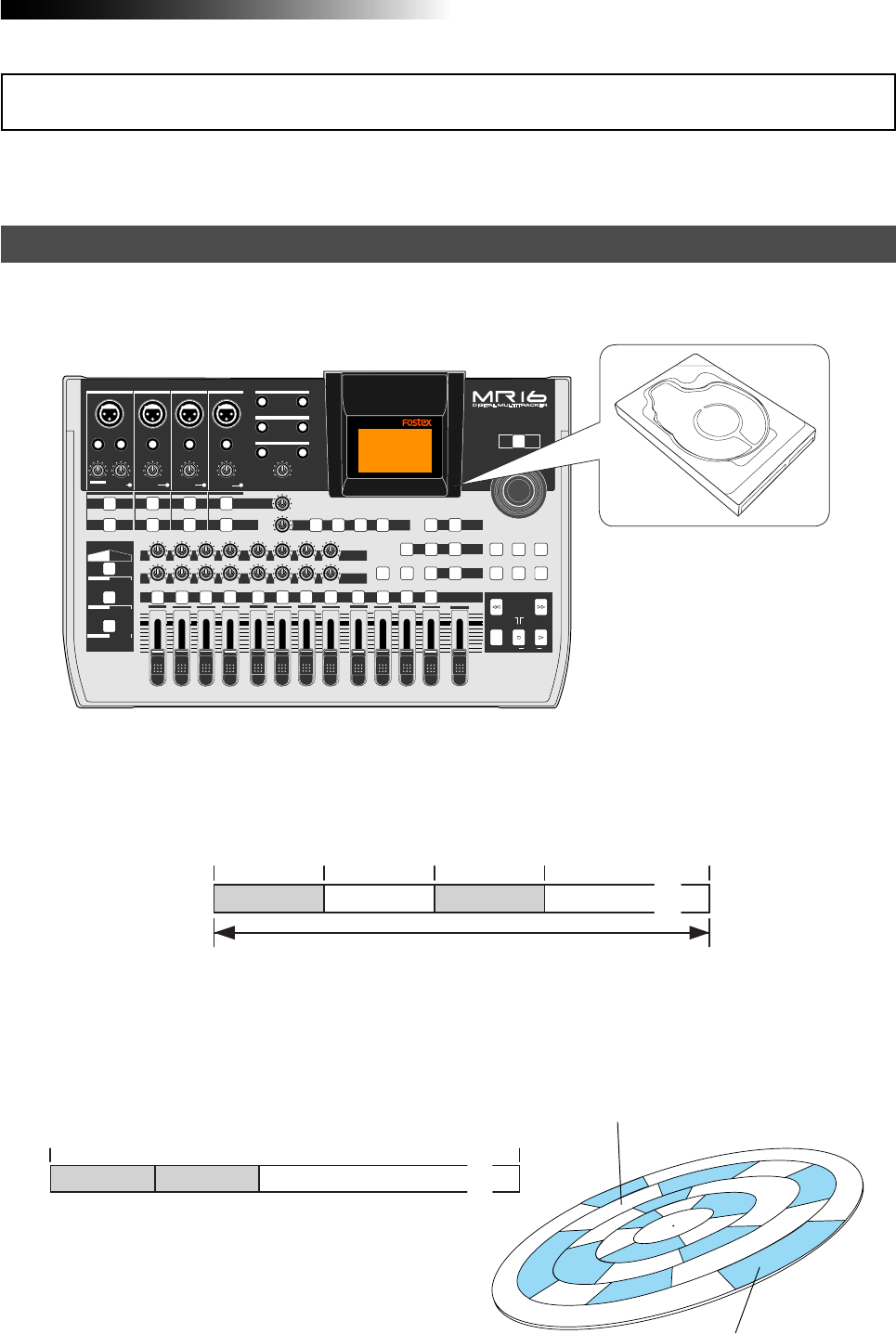
Recording method
The MR16 is fitted with a 3.5-inch hard disk drive. Songs are recorded on a hard disk along with
the ABS time (from 00m 00s 000ms to 399m 59s 999ms).
The ABS time shows the absolute time on a hard disk and you can start recording from any
desired time within the range between 00m 00s 000ms and 399m 59s 999ms ABS time.
As the MR16 does not consume the disk space when no audio is recorded, you can record audio
effectively, while the recordable time for a tape recorder depends on the tape length.
PEAK
GUITAR
MIN
DISTORTION
MAX LINE MIC
TRIM
INSERT/GUITAR
UNBAL
BALBALBALBAL
INPUT A INPUT B INPUT C INPUT D
VOLUME
MIN MAX
PEAK
LINE
TRIM
MIC
UNBAL POWER
UNBAL
MIC
TRIM
LINE
PEAK
UNBAL
MIC
TRIM
LINE
PEAK
MAX
MIN
1
R
L
100
SIMULATION SIMULATION
AMP
MIC
010
LR
010
LR
23
RL
100
4 8
010
LR
7
6
RL
100
RL
100
010
LR
5
MAX
MIN
MASTER
REC SELECT
RECORD STOP PLAY
REWIND F FWD
UNDO/REDO
STORE
LOCATE REC END
LOCATE ABS ZERO
A-B PLAY
BOUNCE
MASTERING
BRIGHT
15/16 > STEREO WAV FILE
NATURAL
POWERFUL
B / OUTA / INPLAY MODEAUTO PUNCH
LOCATE
EFFECT
DELAYPLATEHALLROOM BOUNCE MODE
CONTRAST
TIMEBASE SELECT
RHYTHM GUIDE DIRECT LOCATE
EFFECT SEND
PAN
INPUT EQ
TO STEREO BUSS LEVEL
9/10 11/12 13/14 15/16
ABC1 DEF2 GHI3 JKL4 MNO5 YZ9PQR6 +-_0STU7 VWX8 DELETE
MENU / ENTER
MIN MAX
MIN MAX
REVERB / DELAY TIME
LSTEREO OUT R
1AUX OUT 2
1PHONES 2
DYNAMIC BRIT STACK
CONDENSER US METAL
TUBE 60'S COMBO
INPUT A INPUT B INPUT C INPUT D
The beginning of a song
0m00s000ms
(ABS ZERO) 05m00s000ms 10m00s000ms 15m00s000ms
(REC END) 399m59s999ms
Recorded area Recorded areaNon-recorded area Non-recorded area
......
You can start recording from any desired time within the range
between 00m00s000ms and 399m59s999ms ABS time.
0m00s000ms 399m59s999ms
Non-recorded area (remain) ......
5-minute recording 5-minute recording
Non recorded area (shown in white)
3.5-inch hard disk drive
Recorded area (shown in gray)
The basics of the MR16
14
MR16 Owner’s Manual (Read this chapter first!)
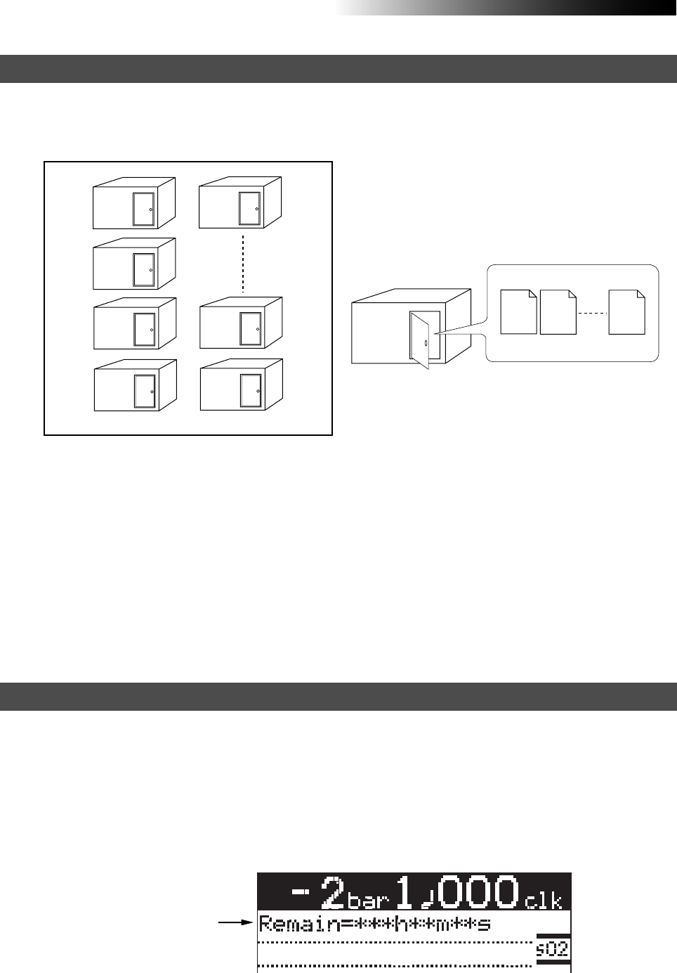
About song
To understand songs, imagine separated rooms as shown below. Each room can be regarded as
a song. With the MR16, you can create up to 99 rooms (songs) on the hard disk (although the
available space may limit the number of songs).
Recorded track data is stored in a song as mono WAV
files, as shown below.
Each song is independent on a disk and you can record, play back or edit a song without affect-
ing other songs. You can give a desired song name for managing recorded songs (see page **).
Recorded track data is stored in a song as mono WAV files.
The MR16 can convert the two WAV files recorded on tracks 15 and 16 (L and R) to a stereo WAV
file (see page 90).
You can burn the converted stereo WAV file to an audio CD. To do this, export the file to your PC
and burn it using a music software application (see page 104), or burn the file to the internal CD-
R/RW drive (if it is provided to your MR16) or to an external CD-R/RW drive connected to the
MR16.
Song01
Track 1 Track 2 Track 16
Song01
Song02
Song03
Song04
Song05
Song99
Song98
Remain (recordable space left on the disk)
"Remain" shows how much time you can further record audio data to the available space left on
the internal hard disk.
As described earlier, the MR16 stripes ABS time from 0m 00s 000ms to 399m 59s 999ms at
maximum for each song. However, the remaining time (= available recording time left) depends
on the available space on the hard disk in actual use. The remaining time is shown as in the
screen example below during recording or record standby. Note that it shows the remaining
time for recording onto a mono track.
A "mono" track means a single track. Therefore, you can calculate the remaining time for record-
ing to more than one track by dividing the displayed time by the number of tracks. Note that the
remaining time shown on the screen is an approximate time.
Remain value
WAV files
15
MR16 Owner’s Manual (Read this chapter first!)
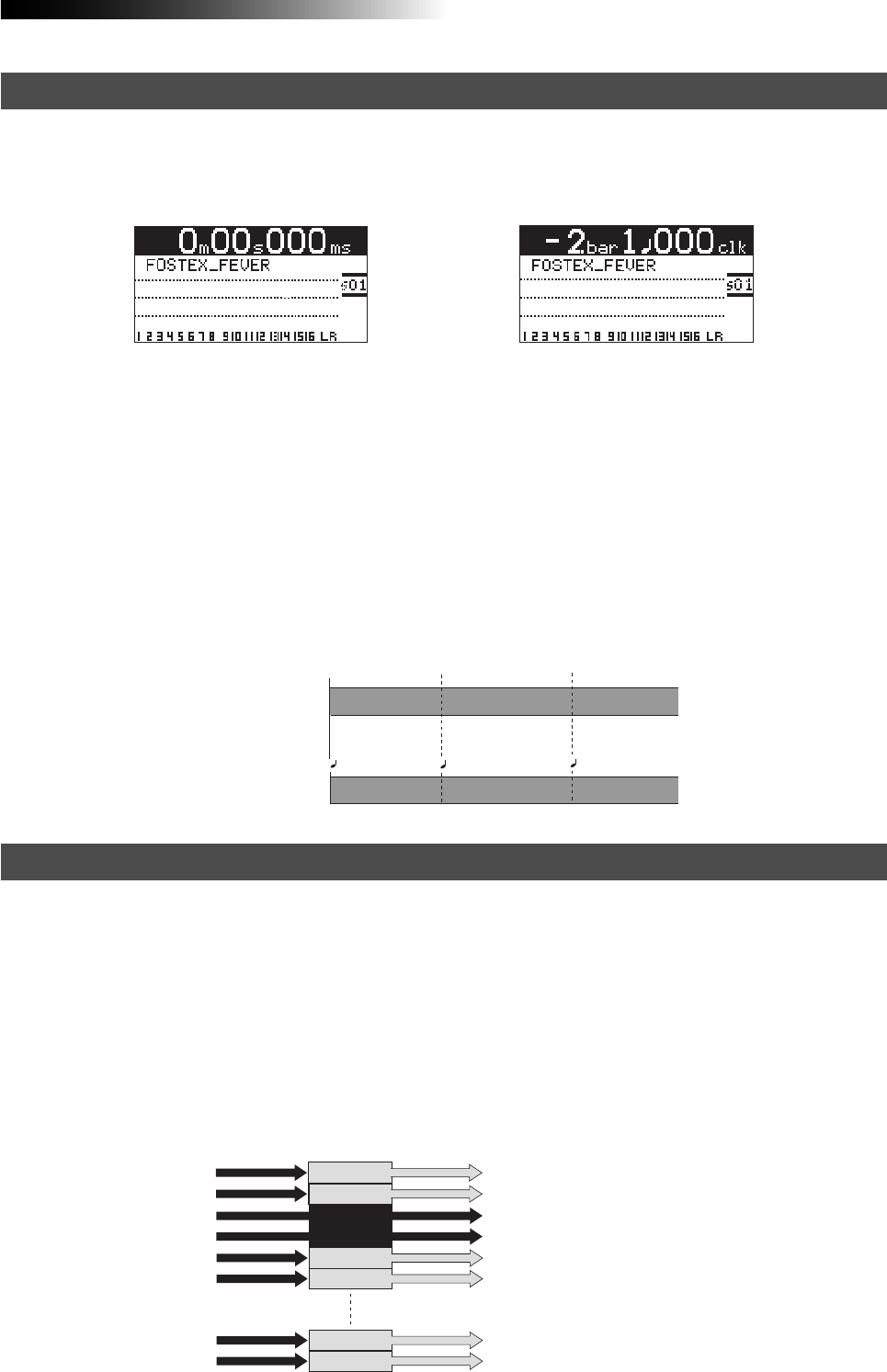
Time base
Input monitor and repro monitor
The term, "time base", is used as the reference of recorder position information.
Using the [TIME BASE SELECT] key, you can select from among two time base modes: ABS time
and bar/beat mode. Each screen example below shows the recorder is located at the beginning of
a song in each time base mode.
<ABS time mode> <Bar/beat mode>
ABS time mode:
ABS time stands for Absolute time, which is "striped" on the disk when creating a song. It starts from
0m 00s 000ms (=ABS zero, the beginning of a song) and ends by 399m 59s 999ms at maximum.
Bar/beat mode:
The bar/beat/clock information is created according to the internal tempo map.
The ABS zero position is set to "bar -2/beat 1/clk 000" by default (this is called "bar offset").
The MR16 determines the bar/beat/clock value in a song in referenced to the bar offset, as well
as the time signature map and tempo map. You can set the bar offset between bar 1 to bar -8 via
the menu mode (see page 95). The figure below shows the relation between two time base
modes.
Each of the MR16 tracks has two output modes: repro monitor and input monitor.
In the repro monitor mode, the track playback signal is output. So if you want to listen to the
track playback sound, select the repro monitor mode.
In the input monitor mode, the input signal fed to the track is output. So you can check the level
of the input signal to be recorded.
To enter a MR16 track to input monitor mode, press the appropriate [REC SELECT] key to arm
the track (i.e. make the track record-ready), then press only the [RECORD] key to enter the
"RECORD READY" mode or press both the [RECORD] and [PLAY] keys simultaneously to start
recording.
Bar/beat mode
The beginning of a song
0m00s000ms
(ABS ZERO) 0m03s000ms 0m06s000ms
1bar 1 000clk 3bar 1 000clk
-2bar 1 000clk
ABS time mode
Input signals for
recorder tracks Output signals from
recorder tracks
Track 1
Track 5
Track 6
Track 15
Track 16
Playback signal (repro monitor)
Playback signal (repro monitor)
Playback signal (repro monitor)
Playback signal (repro monitor)
Playback signal (repro monitor)
Track 3
READY
Track 4
READY
Input signal (input monitor)
Input signal (input monitor)
Track 2 Playback signal (repro monitor)
16
MR16 Owner’s Manual (Read this chapter first!)
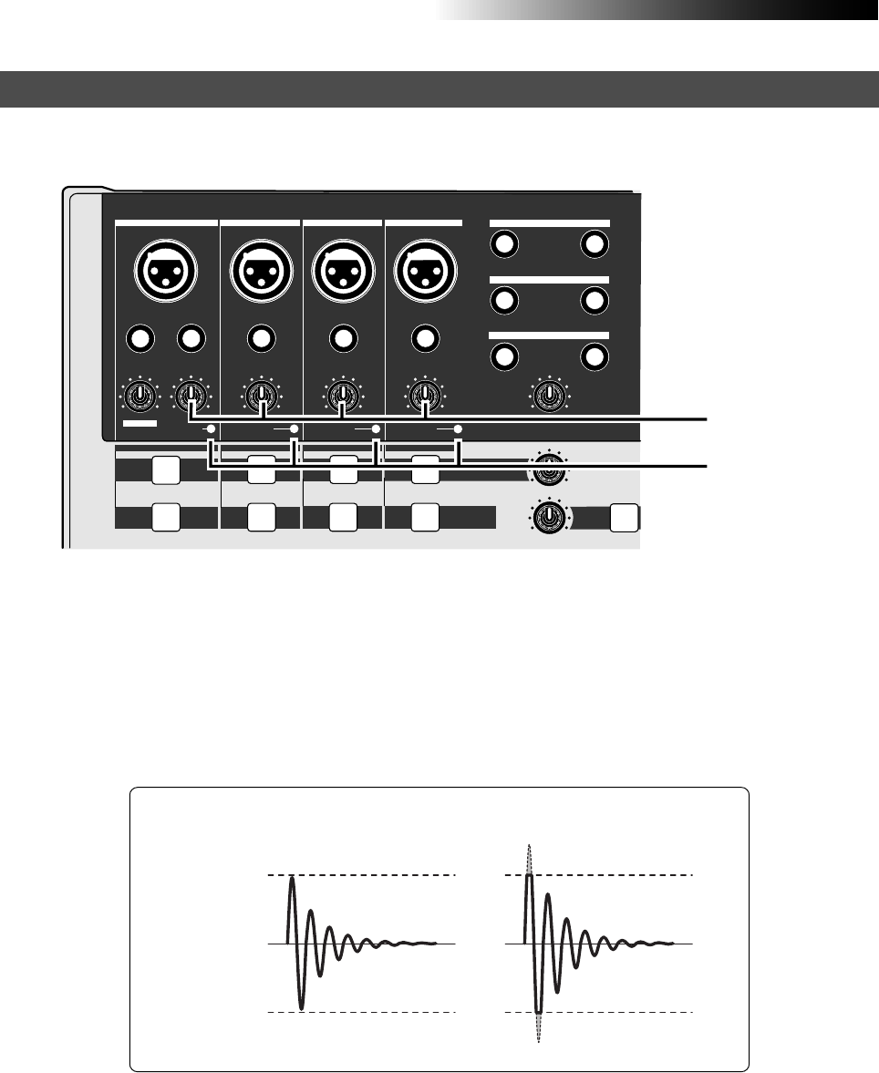
[TRIM] control
You must pay great attention to the [TRIM] control adjustment when recording to the MR16.
The analog signal received at each input ([INPUT A] through [INPUT D]) is sent to the [TRIM]
control, by which the signal level fed to the A/D converter of the MR16 is controlled.
You can check this level by the PEAK indicator. If the level is too high, the PEAK indicator lights,
while you may hear the sound distorted or noisy. This distortion (noise) generated at this stage
cannot be eliminated, therefore, adjust the TRIM control properly so that the PEAK indicator
does not light at the loudest part of the input signal.
[TRIM] control
PEAK LED
Clipping level
Clipping level
Proper level The level is too high.
PEAK
GUITAR
MIN
DISTORTION
MAX LINE MIC
TRIM
INSERT/GUITAR
UNBAL
BALBALBALBAL
INPUT A INPUT B INPUT C INPUT D
VOLUME
MIN MAX
PEAK
LINE
TRIM
MIC
UNBAL UNBAL
MIC
TRIM
LINE
PEAK
UNBAL
MIC
TRIM
LINE
PEAK
ROOM
INPUT EQ
TO STEREO BUSS LEVEL
MIN MAX
MIN MAX
REVERB / DELAY TIME
LSTEREO OUT R
1AUX OUT 2
1PHONES 2
INPUT A INPUT B INPUT C INPUT D
17
MR16 Owner’s Manual (Read this chapter first!)
You can burn an audio CD from songs created by the MR16 multitrack recording function using
either of the following methods.
(1) Burns a CD using the internal CD-R/RW drive (the CD-R/RW drive built-in model only)
(2) Burns a CD using an external CD-R/RW drive
(3) Burns a CD using the CD-R function of a PC
Regardless of the burning methods above, you must carry out the following preparation for
burning an audio CD.
How to burn an audio CD
Mix down recorded track signals and bounce to tracks 15/16.
There are two methods for bouncing tracks to tracks 15/16. One is to bounce to
tracks 15/16 of the same song, while the other is to bounce to tracks 15/16 of the
New song. See pages 75 through 88 for details about track bouncing.
Convert the song data bounced to tracks 15/16 to a stereo WAV file.
A converted stereo WAV file is stored to the "2MIX" folder in the song. When you
create an audio CD, this WAV file is recorded to a CD-R/RW disc. See page 104 for
details about WAV file conversion.
1
2
In short, after preparing the stereo WAV file(s) to be burned, you can burn the file(s) to a CD-R/
RW using either of three burning methods.
• Burning a CD using the internal CD-R/RW drive (the CD-R/RW drive built-in model only)
(1) Use the "CD-RW" menu of the menu mode to burn an audio CD. See the "Using the
CD-R/RW drive" supplement for details.
• Burning a CD using an external CD-R/RW drive
(1) Connect an external CD-R/RW drive to the [USB HOST] port on the rear panel.
(2) Use the "USB HOST" menu of the menu mode to burn an audio CD.
See the "Using the CD-R/RW drive" supplement for details.
• Burning a CD using the CD-R function of a PC
(1) Connect a PC to the [USB] port on the rear panel.
(2) Use the [USB] menu of the menu mode to make USB connection enabled.
(3) Start up WAV Manager supplied by Fostex on your PC.
You can download WAV Manager from the Fostex web site. Access our web site or
ask your local Fostex dealer.
(4) Use the "CD Writer" function of WAV Manager to burn an audio CD using the CD-R/RW drive
connected to your PC.
See page 107 for details about how to connect a PC. See the PDF manual included
in the downloaded file of WAV Manager.

18
MR16 Owner’s Manual (Read this chapter first!)

19
MR16 Owner’s Manual (Names and functions)
Names and functions
This chapter describes the names and functions of the controls, keys,
connectors, etc. on the MR16 top panel, side panel and rear panel, as
well as details of the display. See this chapter whenever you want to
know the function of a control, key, etc.
20
MR16 Owner’s Manual (Names and functions)
These jacks output the stereo (L and R) buss
signals. Connect these jacks to the monitor-
ing equipment or master recorder (see pages
31 and 44).
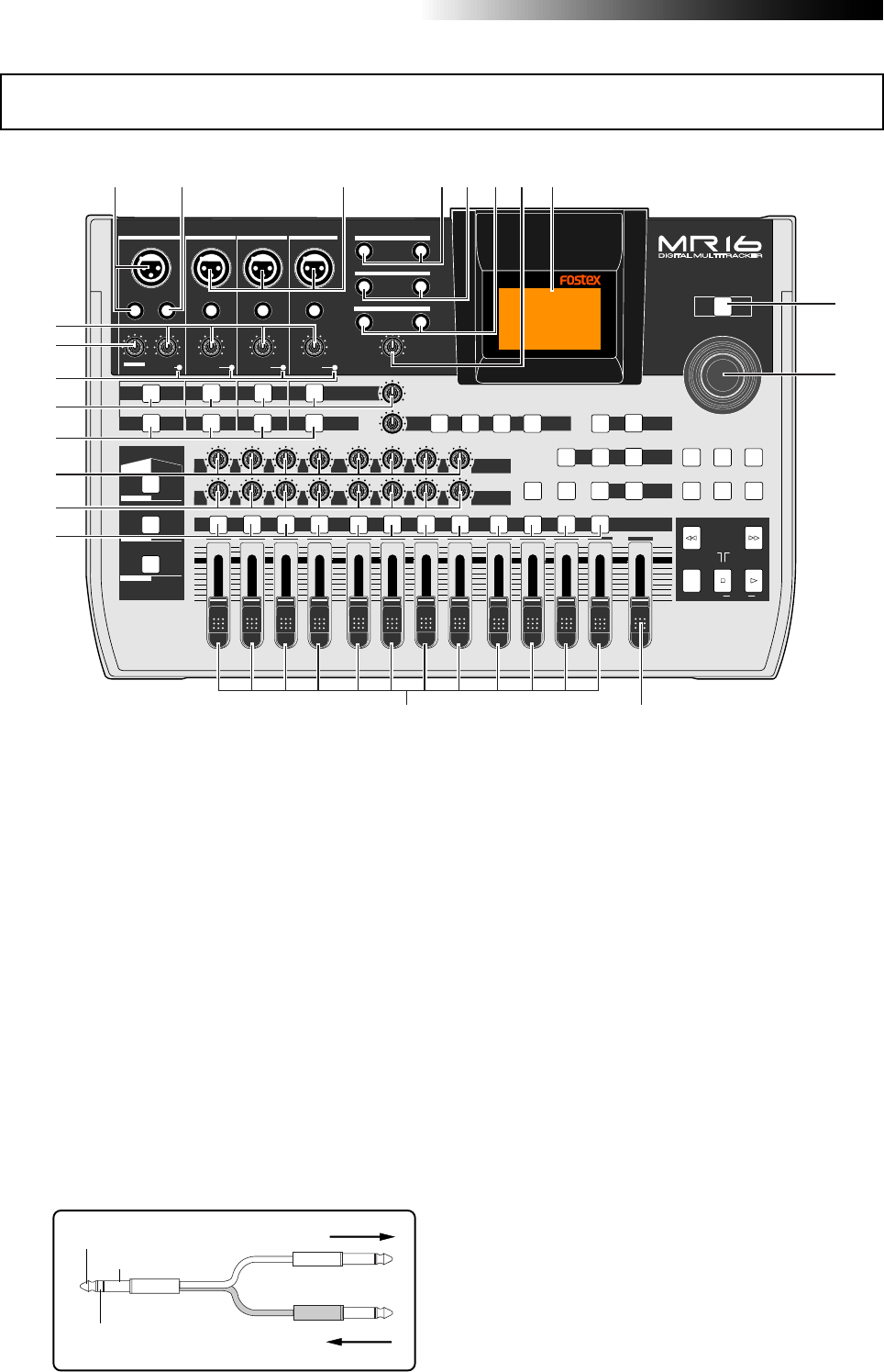
4. [STEREO OUT] jacks (L, R)
1. [INPUT A] input connectors
(XLR connector and phone jack)
3. [INPUT B, C, D] input connectors
(XLR connector and phone jack)
TIP: SEND
RING: RETURN
GND
From the effect output.
To the effect input.
You can connect a microphone, keyboard,
etc. to each of the [INPUT B], [INPUT C] and
[INPUT D] inputs.
Both the [BAL] XLR connector and [UNBAL]
phone jack are provided for each input so
you can use the appropriate connector ac-
cording to the sound source.
If you connect sources to both the XLR con-
nector and phone jack on the same input,
the phone input takes priority (see page 35).
Connects an external effect processor (typi-
cally, a compressor/limiter, etc.).
For connection between the MR16 and the
effect processor, use a Y-cable as shown be-
low (see page 69).
2. [INSERT] connector (TRS phone jack)
Both the [BAL] XLR connector and [UNBAL/
GUITAR] phone jack are provided. You can
connect a guitar, microphone, keyboard, etc.
If you connect sources to both the XLR con-
nector and phone jack, the phone input takes
priority. When using the [INPUT A] section,
select the [INPUT A SELECT] switch on the
rear panel appropriately according to your
usage (see page 35).
Top panel 1
PEAK
GUITAR
MIN
DISTORTION
MAX LINE MIC
TRIM
INSERT/GUITAR
UNBAL
BALBALBALBAL
INPUT A INPUT B INPUT C INPUT D
VOLUME
MIN MAX
PEAK
LINE
TRIM
MIC
UNBAL
POWER
UNBAL
MIC
TRIM
LINE
PEAK
UNBAL
MIC
TRIM
LINE
PEAK
MAX
MIN
1
R
L
100
SIMULATION SIMULATION
AMP
MIC
010
LR
010
LR
23
RL
100
4 8
010
LR
7
6
RL
100
RL
100
010
LR
5
MAX
MIN
MASTER
REC SELECT
RECORD STOP PLAY
REWIND F FWD
UNDO/REDO
STORE
LOCATE REC END
LOCATE ABS ZERO
A-B PLAY
BOUNCE
MASTERING
BRIGHT
15/16 > STEREO WAV FILE
NATURAL
POWERFUL
B / OUTA / INPLAY MODEAUTO PUNCH
LOCATE
EFFECT
DELAYPLATEHALLROOM BOUNCE MODE
CONTRAST
TIMEBASE SELECT
RHYTHM GUIDE DIRECT LOCATE
EFFECT SEND
PAN
INPUT EQ
TO STEREO BUSS LEVEL
9/10 11/12 13/14 15/16
ABC1 DEF2 GHI3 JKL4 MNO5 YZ9PQR6 +-_0STU7 VWX8 DELETE
MENU / ENTER
MIN MAX
MIN MAX
REVERB / DELAY TIME
LSTEREO OUT R
1AUX OUT 2
1PHONES 2
DYNAMIC BRIT STACK
CONDENSER US METAL
TUBE 60'S COMBO
INPUT A INPUT B INPUT C INPUT D
1234567
8
9
10
11
12
13
14
15
16
17
18
19
20
These jacks can output the playback signal
of any of tracks 1 through 16, the effect send
buss signal or the internal click (see page
150). You can select the output signal of each
AUX OUT independently using the "System"
menu of the menu mode (see page 146 for
details).
5. [AUX OUT] jacks (1, 2)

21
MR16 Owner’s Manual (Names and functions)
<Note>:
If you do not use the MR16 for a
long time, we recommend unplugging the
power cord from the AC outlet.
13. [REC SELECT] keys
20. [TRIM] controls
Each control adjusts the input gain of the
corresponding input channel (see page 16,
and 37 through 42).
19. [DISTORTION] control
Controls the amount of the distortion effect
for a guitar connected to the [XLR] connec-
tor or [UNBAL/GUITAR] jack (phone type) on
the [INPUT A] channel.
This control is effective only when the [IN-
PUT A SELECT] switch is set to "GTR/DIST"
(see pages 35 and 68).
18. [PEAK] indicators
Each indicator lights when the input signal
is overloaded (see page 16). You should ad-
just the input gain using the [TRIM] control
so that the [PEAK] indicator does not light.
17. [TO STEREO BUSS] keys
[TO STEREO BUSS LEVEL] control
Each of the [TO STEREO BUSS] key selects
whether or not sending the corresponding
input signal to the stereo L/R busses (see
page 85). Each press of the key alternates
ON and OFF. When ON, the key illuminates
in green. When OFF, it is unlit. When the
corresponding input is assigned to a record-
ing track, the key flashes in green.
A long press of the key enters the input menu
of the MENU mode, in which you can set
phantom power on/off, panning, etc. (see
pages 86 and 144).
The [TO STEREO BUSS LEVEL] control adjusts
the level of the signal sent to the stereo L/R
buss.
14. [PAN] controls
Control panning for tracks 1 through 8.
Used to select the recording track(s). You can
record onto up to four tracks simultaneously.
Pressing a key arms or unarms the corre-
sponding track(s).
Tracks 9/10, 11/12, 13/14 or 15/16 are
armed or unarmed simultaneously (see
pages 36).
In the menu mode, these keys are used for
entering or deleting characters .
Each fader adjusts the track playback level.
Each of track faders 9/10, 11/12, 13/14 and
15/16 controls the stereo signal (see pages
37 through 45).
12. Track faders
Adjusts the stereo (L and R) buss output level
(see pages 37 through 45).
11. [MASTER] fader
Turn on or off the power of the unit (see
page 30). To turn off the power when the
power is on, press and hold down the
[POWER] switch for a few seconds.
9. [POWER] switch
Adjusts the headphone output level.
7. [PHONES VOL] control
Two jacks (1 and 2) are provided. You can
use two pairs of stereo headphones with the
MR16 (see page 31).
6. [PHONES] jacks (1, 2)
8. LCD display
This 132 x 64 dot LCD display shows vari-
ous information (see page 26).
10. [MENU/ENTER] rotary / push knob
Pressing this knob enters the menu mode
(see page 28).
In the menu mode, rotating this knob se-
lects the item or numeric value, while press-
ing this knob confirm the setting/selection.
16. [INPUT EQ] keys
Each key selects whether or not applying the
internal input EQ to the corresponding in-
put signal.
Each press of the key alternates ON and OFF
of the EQ (see page 66).
You can select a desired EQ setting from
among 33 EQ presets available in the EQ li-
brary (see page 67).
A long press of the key enters the menu mode
for selecting the desired EQ library entry (see
page 66).
15. [EFFECT SEND] controls
Control the amount of signals from tracks 1
through 8 sent to the internal effect (reverb
or delay) (see page 72).
22
MR16 Owner’s Manual (Names and functions)
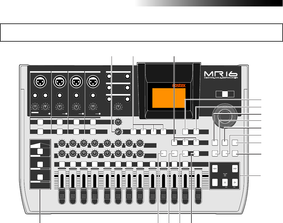
23. [MASTERING] keys
(POWERFUL / NATURAL / BRIGHT)
Used to select the desired mastering effect
during track bounce or mixdown. You can
select from three effect types by pressing an
appropriate key (see page 74).
25. [15/16 > STEREO WAV FILE] key
This key is used when converting a mono
WAV file recorded on tracks 15/16 to a ste-
reo WAV file (see page 104). A converted
stereo WAV file can be exported to a USB-
connected personal computer (see page
107), or can be burned to an audio CD us-
ing the internal CD-R/RW drive or an exter-
nal CD-R/RW drive (see the supplementary
manual "How to use the CD-R/RW drive").
Top panel 2
PEAK
GUITAR
MIN
DISTORTION
MAX LINE MIC
TRIM
INSERT/GUITAR
UNBAL
BALBALBALBAL
INPUT A INPUT B INPUT C INPUT D
VOLUME
MIN MAX
PEAK
LINE
TRIM
MIC
UNBAL
POWER
UNBAL
MIC
TRIM
LINE
PEAK
UNBAL
MIC
TRIM
LINE
PEAK
MAX
MIN
1
R
L
100
SIMULATION SIMULATION
AMP
MIC
010
LR
010
LR
23
RL
100
4 8
010
LR
7
6
RL
100
RL
100
010
LR
5
MAX
MIN
MASTER
REC SELECT
RECORD STOP PLAY
REWIND F FWD
UNDO/REDO
STORE
LOCATE REC END
LOCATE ABS ZERO
A-B PLAY
BOUNCE
MASTERING
BRIGHT
15/16 > STEREO WAV FILE
NATURAL
POWERFUL
B / OUTA / INPLAY MODEAUTO PUNCH
LOCATE
EFFECT
DELAYPLATEHALLROOM BOUNCE MODE
CONTRAST
TIMEBASE SELECT
RHYTHM GUIDE DIRECT LOCATE
EFFECT SEND
PAN
INPUT EQ
TO STEREO BUSS LEVEL
9/10 11/12 13/14 15/16
ABC1 DEF2 GHI3 JKL4 MNO5 YZ9PQR6 +-_0STU7 VWX8 DELETE
MENU / ENTER
MIN MAX
MIN MAX
REVERB / DELAY TIME
LSTEREO OUT R
1AUX OUT 2
1PHONES 2
DYNAMIC BRIT STACK
CONDENSER US METAL
TUBE 60'S COMBO
INPUT A INPUT B INPUT C INPUT D
21 22 23
31
35
36 34 33
32
30
29
28
27
26
25
24
37
These keys are used to select the effect type.
You can select from three reverb types
(ROOM, HALL and PLATE) and a delay
(DELAY). The selected key is lit (see page 70).
22. [EFFECT] keys
(ROOM / HALL / PLATE / DELAY)
21. [REVERB/DELAY TIME] control
This control adjusts the reverb time or de-
lay time. When you select "ROOM", "HALL"
or "PLATE" for the effect type, it adjusts the
reverb time.When you select "DELAY", it
adjusts the delay time (See page 71).
27. [RHYTHM GUIDE] key
Switches on/off of the rhythm guide func-
tion (see page 90). Each press of the switch
alternates on and off. A long press of the
key enters the rhythm guide menu, in which
you can set the rhythm guide parameters
(see page 91).
26. [TIME BASE SEL] key
Selects the time base shown on the display
(see page 15). Each press of the key switch
between "time" and "bar/beat".
24. [BOUNCE MODE] key
Used to select the bounce mode.
Each press of the key switches the bounce
mode (see page 78).

23
MR16 Owner’s Manual (Names and functions)
30. [UNDO/REDO] key
Used to undo or redo recording or editing
(see pages 38, 40, 42, 119 and 127).
Each press of the key alternates "undo" and
"redo".
28. [STORE] key
Stores the current recorder position (time
data) as the LOCATE A/IN or LOCATE B/OUT
point (see page 53).
In the "2-mix file playback" mode, pressing this
key sets a CUE point to the current stereo
WAV file (see the supplementary manual
"How to use the CD-R/RW drive").
33. [LOCATE B/OUT] key
Pressing this key while holding down the
[STORE] key sets the LOCATE B point (or
punch out point) (see pages 53 and 62).
32. Transport keys
[PLAY] key
Starts playback of the recorder.
Pressing this key while holding down the
[RECORD] key starts recording of the armed
(record-ready) track(s).
Pressing this key during recording exits re-
cording.
Pressing this key in the direct locate mode
executes the preview playback for a few sec-
onds after the locate point (see page 58).
[STOP] key
Stops the recorder.
By pressing the [PLAY], [REWIND] or [F FWD]
key while holding down the [STOP] key, you
can locate to a specific point or repeat play-
back as below.
• [STOP] + [PLAY] (A-B PLAY)
Repeats playback between the LOCATE A and
LOCATE B points (see page 48).
• [STOP] + [REWIND] (LOCATE ABS ZERO)
Locates to the beginning (ABS ZERO) of the
current song (see page 52).
• [STOP] + [F FWD] (LOCATE REC END)
Locates to the recording end of the current
song (REC END) (see page 52).
[RECORD] key
Pressing the [PLAY] key while holding down
the [RECORD] key starts recording of the
armed (record-ready) track(s).
By pressing only the [RECORD] key when any
track(s) is armed (in record-ready), the in-
put signal(s) of the armed track(s) can be
monitored (i.e. input monitor mode). (see
pages 37 through 42).
Pressing this key in the direct locate mode
executes the preview playback for a few sec-
onds before the locate point (see page 58).
[F FWD] key
Pressing this key fast forwards the recorder.
During playback, pressing this key starts 3 x
cueing (see page 48).
While holding down the [STOP] key, press-
ing this key locates to the recording end of
the current song (REC END) (see page 52).
[REWIND] key
Pressing this key rewinds the recorder.
During playback, pressing this key starts 3 x
reverse cueing (see page 48).
While holding down the [STOP] key, press-
ing this key locates to the beginning (ABS
ZERO) of the current song (see page 52).
This key is also used to go up the menu
screen layer while a menu screen is dis-
played.
34. [LOCATE A/IN] key
Pressing this key while holding down the
[STORE] key sets the LOCATE A point (or
punch in point) (see pages 53 and 62).
35. [PLAY MODE] key
Selects a play mode. You can select from
among normal, auto play, auto return and
loop (see page 49).
36. [AUTO PUNCH] key
Turns on or off the auto punch mode (see
page 63).
29. [CONTRAST] key
By rotating the [MENU/ENTER] knob while
holding down this key, you can adjust the
display contrast (see page 27).
37. Insert effect selection keys
Used to select the insert effect (mic simula-
tion or amp simulation) for the signal from
the [INPUT A] jack.
When setting the [INPUT A SELECT] switch
on the rear panel to "MIC/LINE", you can use
the mic simulation effect. When setting the
switch to "GTR/DIST", you can use the guitar
amp simulation effect (see page 68).
31. [DIRECT LOCATE] key
Each press of this key alternates ON and OFF
of the direct locate mode (see page 55).
24
MR16 Owner’s Manual (Names and functions)
Either of the [BAL] XLR and
[UNBAL/GUITAR] phone connec-
tors can be used. Set the switch to
this position when the source is an
external microphone or line level
source.
MIC/LINE
GTR DIST
GTR CLEAN
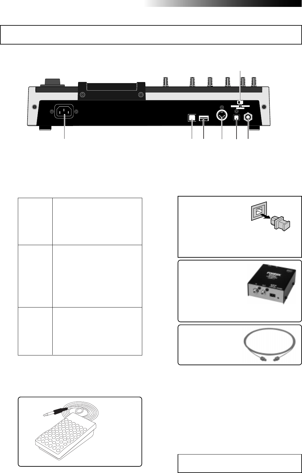
3. [DIGITAL OUT] connector
(Toslink optical connector)
4. [MIDI OUT] jack (DIN 5-pin connector)
If you need to connect the
unit to a digital device which
only provides a coaxial type
digital connector (typically,
an RCA pin jack), use the
Fostex COP-1/96k coaxial-
optical converter (shown
right).
<Note>:
The dust protec-
tion cap is inserted to
the [
DIGITAL OUT
] con-
nector when the unit is
shipped.
Remove the cap when you use this connec-
tor. If you do not use this connector, attach
the dust protection cap.
2. [FOOT SW] jack (TRS phone jack)
unlatched-type footswitch
Either of the [BAL] XLR and
[UNBAL/GUITAR] phone connec-
tors can be used. You can adjust
the input level and distortion using
the [TRIM] and [DISTORTION]
controls respectively. You can also
use the amp simulation insert ef-
fect.
Either of the [BAL] XLR and
[UNBAL/GUITAR] phone connec-
tors can be used. You can adjust
the input level using the [TRIM]
control. You can also use the amp
simulation insert effect.
Model COP-1/96k
Use an optical digital
cable with Toslink plugs
on both ends.
<Caution>:
Do not connect your personal
computer to the [
USB HOST
] port.
1. [INPUT A SELECT] switch
This switch must be set appropriately accord-
ing to the input source of the [INPUT A] chan-
nel (see page 35).
Used to connect with an unlatched-type
footswitch (see page 61).
Used to connect with an external digital de-
vice using an optical cable (see page 45).
Used to connect to a MIDI IN jack of an ex-
ternal MIDI device (such as a MIDI se-
quencer) (see pages 100 and 102).
5. [USB HOST] connector (USB A type)
Used to connect to an external CD-R/RW
drive for creating an audio CD (CD-DA).
See the supplementary manual "How to use
the CD-R/RW drive" for details.
Rear panel
USB USB HOST MIDI OUT DIGITAL OUT FOOT SW
INPUT A SEL
GTR CLEAN MIC/LINE
GTR DIST
1
2
34
56
7
25
MR16 Owner’s Manual (Names and functions)
6. [USB] port (USB B type)
Used to connect with a personal computer
using a standard USB cable for song file data
transfer between the MR16 and the personal
computer (see page 107).
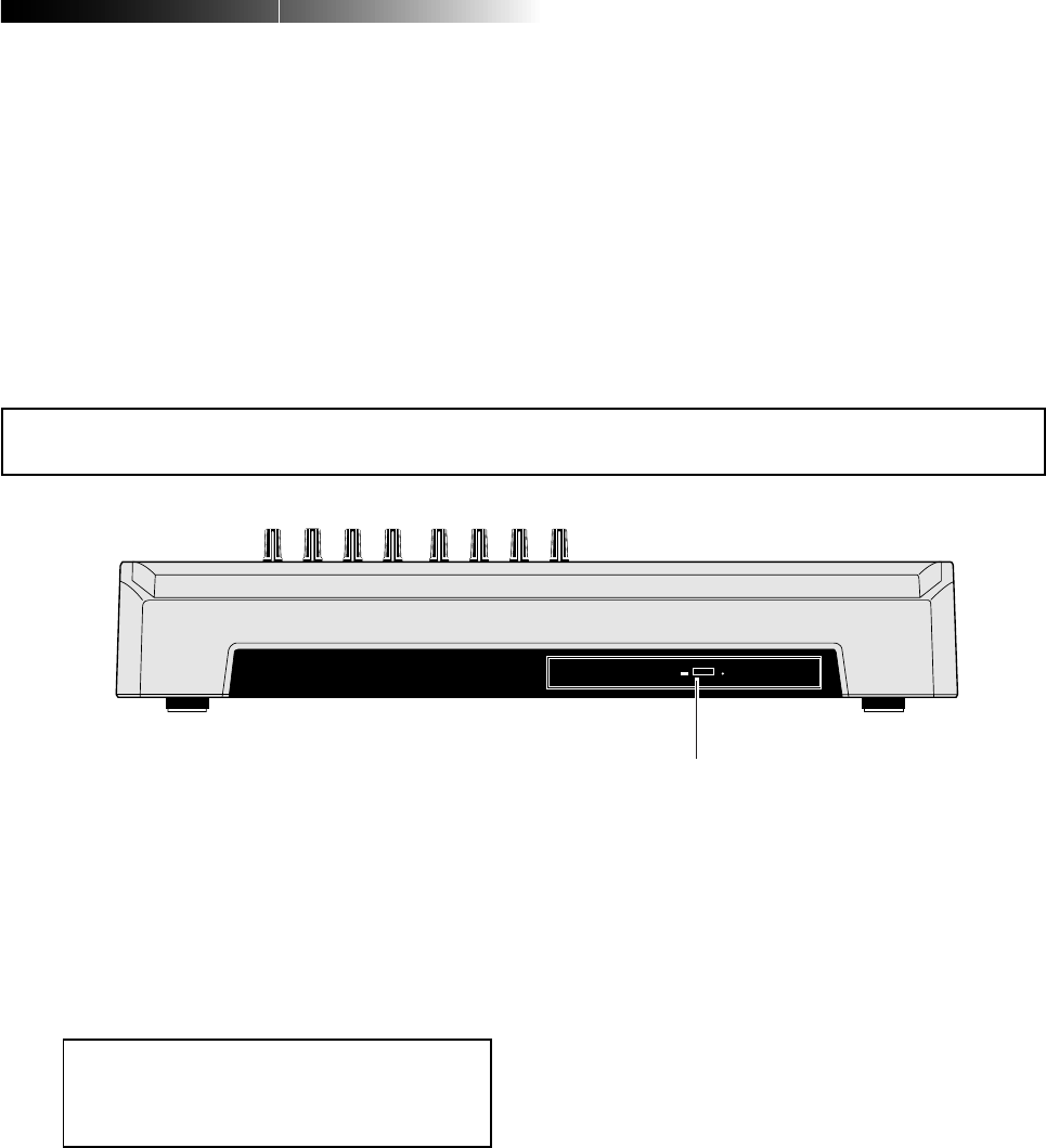
Front panel (CD-R/RW drive built-in model only)
<Caution>:
Although you can see the DVD-
ROM logo on the front of the CD-R/RW drive
tray, it does not support DVD ROM discs.
Only CD-R/RW discs can be used.
1. Internal CD-R/RW drive
Used to create an original audio CD by burn-
ing converted stereo WAV files to a CD-R/
RW disc, or used to record a single mono
WAV file converted from track data on the
HDD to a CD-R/RW disc (see the supplemen-
tary manual "How to use the CD-R/RW drive"
for details).
1
7. [AC IN] connector
Connect the supplied power cord to this con-
nector (see page 30).
26
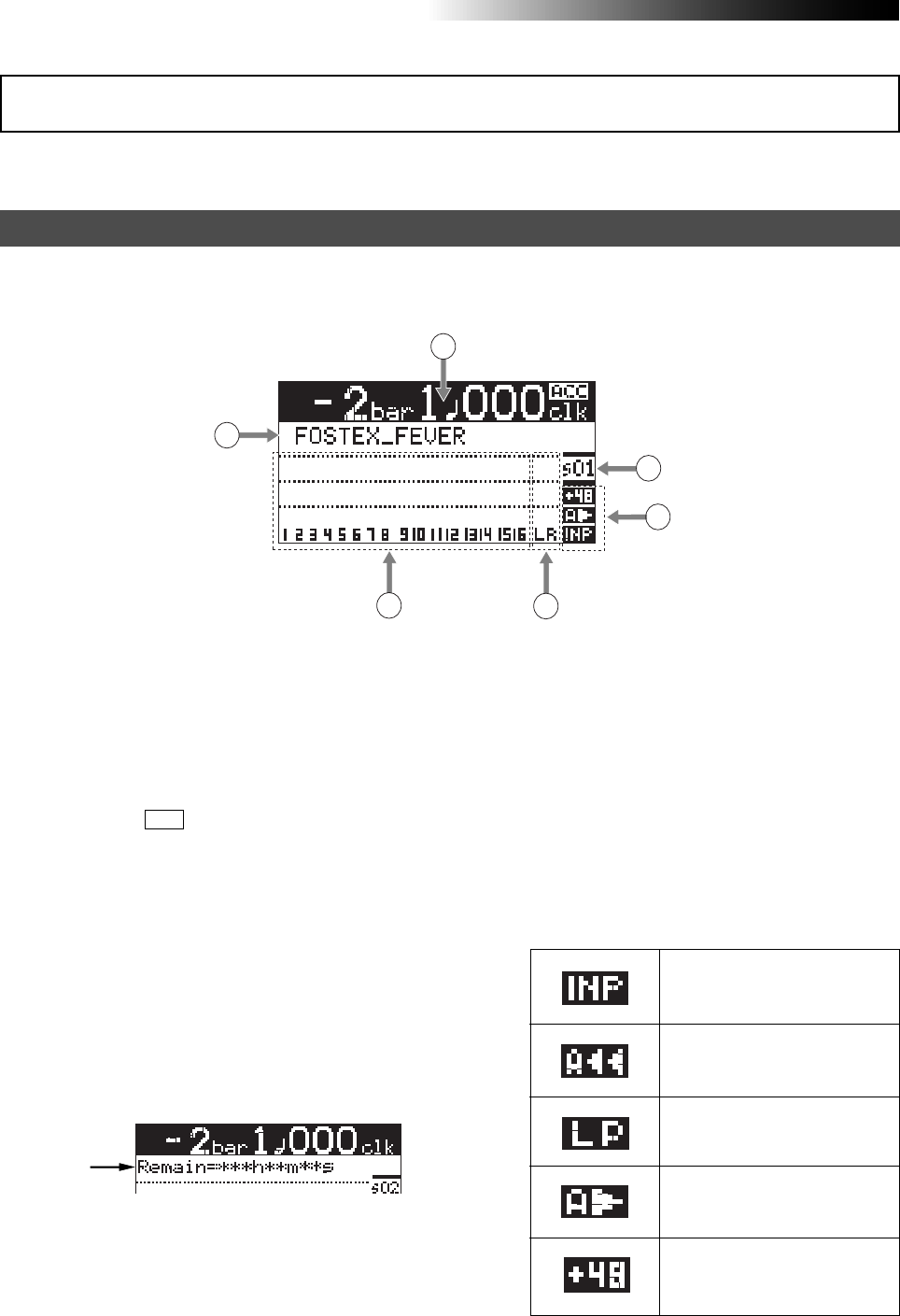
MR16 Owner’s Manual (Names and functions)
When turning on the MR16, the display shows the startup screen (showing the startup status of the MR16),
followed by the "Home" screen, which is similar to the one below. In this condition, the previously loaded
song is loaded and the recorder is located at the beginning of the song. The home screen provides the
following information.
The following describes details about the LCD display, including screen contents and opera-
tion.
1. Time counter display
6. Song number display
4. Stereo buss (L and R) level display
5. Song status display
At least one of the tracks is in the
input monitor mode (see pages
38, 40 and 42).
The auto return mode is active
(see page 49).
3. Track level display
The remain time shows how much time you
can further record audio data onto a mono
track using the available space left on the hard
disk.
2. Character display
The loop mode is active (see page
49).
Home screen
The auto play mode is active (see
page 49).
1
2
34
5
6
Time information of the current recorder po-
sition is shown in ABS or bar/beat mode (by
default, bar/beat). Using the [TIME BASE SE-
LECT] key, you can select a desired time base
mode. When the recorder is moving (playing
back, fast forwarding, etc.), the appropriate
icon is also shown. While the hard disk drive is
in access, " ACC " lights up.
Normally, the name of the song currently
loaded is shown (up 22 characters can be
shown at a time).
It also shows following information.
• A name of the operation mode currently
being executed (such as BOUNCE 1-8->9/10).
• A (not-so-serious) warning message
• The "Remain" time when at least one track is
record-armed (i.e. At least one of the
[REC SELECT] keys is active).
The recording or playback levels of tracks 1
through 16 are shown. When a track is record
armed, the track number indication changes
to the source input channel (any of A, B, C and
D).
During recording or playback, the output lev-
els of the L/R stereo buss are shown.
Lights up the following status icons when the
appropriate modes (functions) are active.
Shows the song number of the song currently
loaded.
LCD display
The +48V phantom power is be-
ing supplied (seepage 144).
27
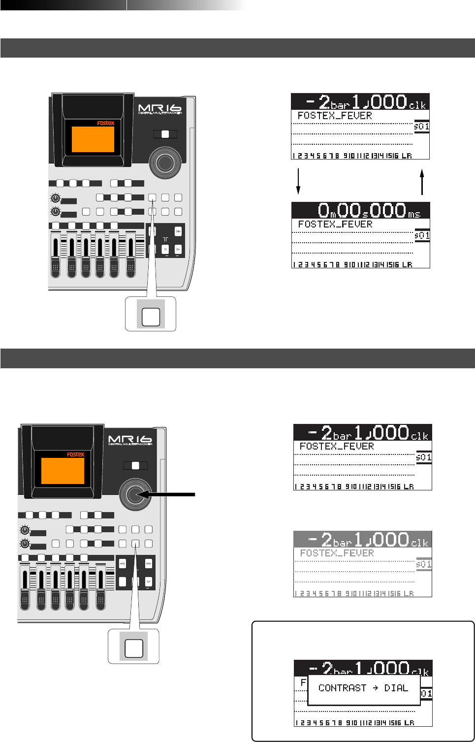
MR16 Owner’s Manual (Names and functions)
When the display shows the home screen, pressing the [TIME BASE SELECT] key switches the time base
mode between ABS and bar/beat.
Example of ABS display
Example of bar/beat display
You can adjust the display contrast by rotating the [MENU/ENTER] knob while holding down the [CON-
TRAST] key. Rotating the dial clockwise heightens the contrast, while rotating it counterclockwise lowers
the contrast.
[MENU/ENTER] knob
[CONTRAST] key
[TIME BASE SELECT] key
<High contrast>
<Low contrast>
Selecting a time base mode
Adjusting the display contrast
While pressing down the [CONTRAST] key, the
display shows "CONTRAST -> DIAL".
POWER
8
010
LR
MAX
MIN
MASTER
REC SELECT
RECORD STOP PLAY
REWIND F FWD
UNDO/REDO
STORE
LOCATE REC END
LOCATE ABS ZERO
A-B PLAY
BOUNCE
MASTERING
BRIGHT
15/16 > STEREO WAV FILE
NATURAL
POWERFUL
B / OUTA / INPLAY MODEAUTO PUNCH
LOCATE
EFFECT
DELAYPLATEHALL BOUNCE MODE
CONTRAST
TIMEBASE SELECT
RHYTHM GUIDE DIRECT LOCATE
EFFECT SEND
PAN
9/10 11/12 13/14 15/16
YZ9 +-_0VWX8 DELETE
MENU / ENTER
SELECT
TIMEBASE
POWER
8
010
LR
MAX
MIN
MASTER
REC SELECT
RECORD STOP PLAY
REWIND F FWD
UNDO/REDO
STORE
LOCATE REC END
LOCATE ABS ZERO
A-B PLAY
BOUNCE
MASTERING
BRIGHT
15/16 > STEREO WAV FILE
NATURAL
POWERFUL
B / OUTA / INPLAY MODEAUTO PUNCH
LOCATE
EFFECT
DELAYPLATEHALL BOUNCE MODE
CONTRAST
TIMEBASE SELECT
RHYTHM GUIDE DIRECT LOCATE
EFFECT SEND
PAN
9/10 11/12 13/14 15/16
YZ9 +-_0VWX8 DELETE
MENU / ENTER
CONTRAST

28
MR16 Owner’s Manual (Names and functions)
If a serious problem happens to the MR16 during operation, an appropriate warning message is shown on
the display. Most warning messages are being shown until the [MENU/ENTER] knob is pressed.
Note that there are also not-so-serious warning messages besides the following.
Pressing the [MENU/ENTER] knob while the recorder is stopped enters the menu mode and brings up the
menu screen. In the menu mode, you can make setting or editing via the appropriate screen. The top menu
screen has two pages, in which you can select the desired menu by rotating the [MENU/ENTER] knob.
[MENU/ENTER] knob <First page>
This message is shown
when you are going to
delete a song which is
protected.
This message is shown
when the hard disk
drive has a problem.
This message is shown
when you are going to
edit a track or part but
there is not enough
space on the hard disk
for executing the undo
function.
During recording, this
message is shown if
there is no more space
left on the hard disk for
recording.
This message is shown
when you are going to
make recording or ed-
iting to a song which is
protected.
This message is shown
when you are going to
create a new song
while 99 songs exist on
the hard disk.
<Second page>
MENU mode screen
Warning message
POWER
8
010
LR
MAX
MIN
MASTER
REC SELECT
RECORD STOP PLAY
REWIND F FWD
UNDO/REDO
STORE
LOCATE REC END
LOCATE ABS ZERO
A-B PLAY
BOUNCE
MASTERING
BRIGHT
15/16 > STEREO WAV FILE
NATURAL
POWERFUL
B / OUTA / INPLAY MODEAUTO PUNCH
LOCATE
EFFECT
DELAYPLATEHALL BOUNCE MODE
CONTRAST
TIMEBASE SELECT
RHYTHM GUIDE DIRECT LOCATE
EFFECT SEND
PAN
9/10 11/12 13/14 15/16
YZ9 +-_0VWX8 DELETE
MENU / ENTER

29
MR16 Owner’s Manual (Basic operations)
Basic operations
This chapter describes power connection, power on/off, demo song play-
back, etc., as well as basic multitrack recording.
If it is the first time for you to use a Multitracker, read this chapter
carefully first so that you are familiar with the MR16 basic operations,
then read other sections which describe advanced operations.
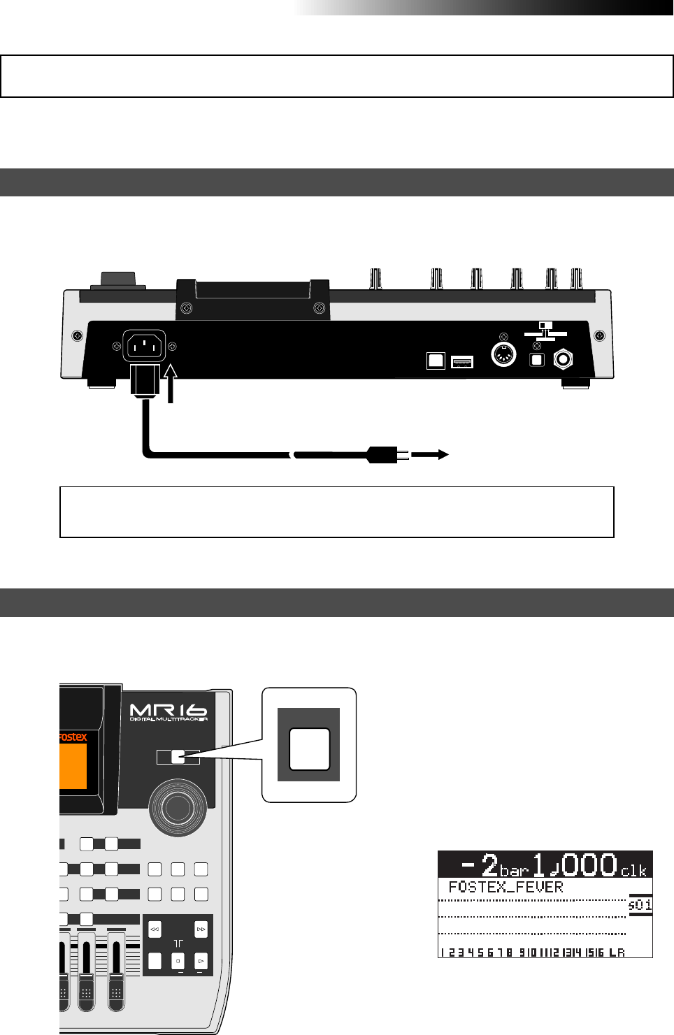
30
MR16 Owner’s Manual (Basic operations)
The MR16 operates by AC power. Before you start using the MR16, you must connect the sup-
plied power cord.
USB USB HOST MIDI OUT DIGITAL OUT FOOT SW
INPUT A SEL
GTR CLEAN MIC/LINE
GTR DIST
Connect between the [AC IN] connector on the MR16 rear panel and an AC outlet using the supplied
power cord.
Power connection
AC outlet
Supplied power cord
You can turn on or off the MR16 power using the [POWER] switch (pointed by an arrow below).
To turn off the power, press and hold down the [POWER] switch for a few seconds.
Turning on the unit
POWER
MAX
MIN
MASTER
REC SELECT
RECORD STOP PLAY
REWIND F FWD
UNDO/REDO
STORE
LOCATE REC END
LOCATE ABS ZERO
A-B PLAY
BOUNCE
MASTERING
BRIGHT
15/16 > STEREO WAV FILE
NATURAL
W
ERFUL
B / OUTA / IN
Y
MODE
LOCATE
T
BOUNCE MODE
CONTRAST
TIMEBASE SELECT
RHYTHM GUIDE DIRECT LOCATE
3
/14 15/16
DELETE
MENU / ENTER
POWER
[POWER] switch
[AC IN] connector
<Note>:
When you do not operate the MR16 for a long period of time, we recommend
disconnecting the power cord.
When you press the [POWER] switch to
turn on the power for the first time, the
MR16 starts up and the display shows the
screen as below (note that it takes some
time until the screen as below is shown).
This screen shows that the demo song is
loaded and stopped at the beginning (ABS
0) of the song named "FOSTEX_FEVER".
Follow the procedure described on the
next page to play back the demo song.
About power
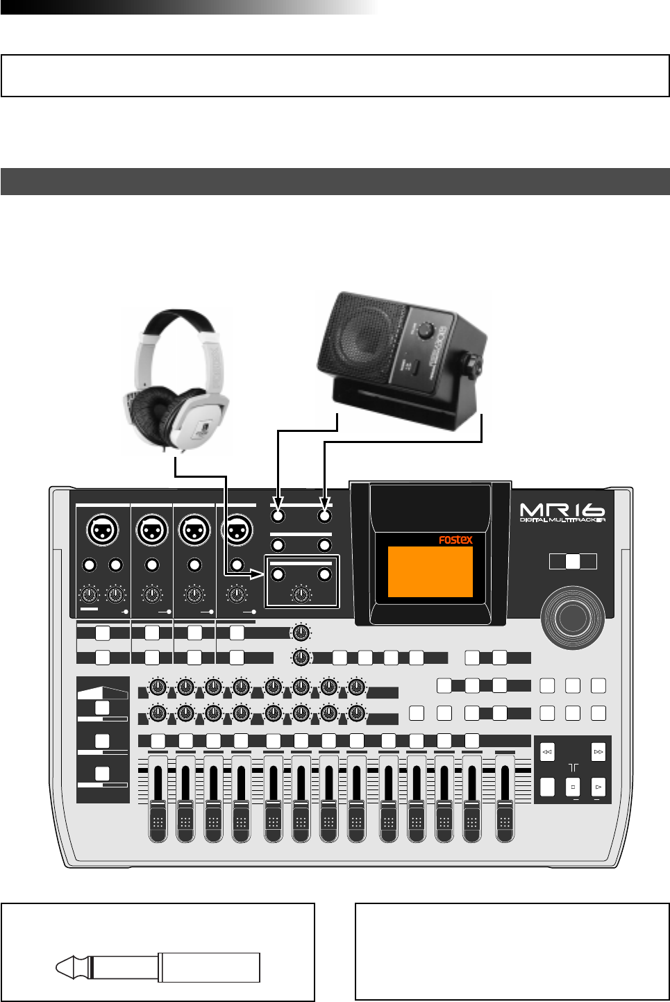
31
MR16 Owner’s Manual (Basic operations)
Connect headphones to either of the two [PHONES] jacks of the MR16. Both jacks feed the same signal
so you may connect headphones whichever you like.
If you have a powered monitor speaker, you may connect it to the [STEREO OUT] L or R jacks of the
MR16.
Connecting headphones (or a monitor speaker system)
<Note>:
When you connect a powered monitor
speaker to the unit, turn down the volume of the
powered monitor speaker to minimum before you
turn on the MR16 and the powered monitor
speaker.
A demo song is pre-recorded on the hard disk of the MR16 when shipped.
Before you make recording, let's listen to the demo song via headphones (or a monitor speaker).
PEAK
GUITAR
MIN
DISTORTION
MAX LINE MIC
TRIM
INSERT/GUITAR
UNBAL
BALBALBALBAL
INPUT A INPUT B INPUT C INPUT D
VOLUME
MIN MAX
PEAK
LINE
TRIM
MIC
UNBAL
POWER
UNBAL
MIC
TRIM
LINE
PEAK
UNBAL
MIC
TRIM
LINE
PEAK
MAX
MIN
1
R
L
100
SIMULATION SIMULATION
AMP
MIC
010
LR
010
LR
23
RL
100
4 8
010
LR
7
6
RL
100
RL
100
010
LR
5
MAX
MIN
MASTER
REC SELECT
RECORD STOP PLAY
REWIND F FWD
UNDO/REDO
STORE
LOCATE REC END
LOCATE ABS ZERO
A-B PLAY
BOUNCE
MASTERING
BRIGHT
15/16 > STEREO WAV FILE
NATURAL
POWERFUL
B / OUTA / INPLAY MODEAUTO PUNCH
LOCATE
EFFECT
DELAYPLATEHALLROOM BOUNCE MODE
CONTRAST
TIMEBASE SELECT
RHYTHM GUIDE DIRECT LOCATE
EFFECT SEND
PAN
INPUT EQ
TO STEREO BUSS LEVEL
9/10 11/12 13/14 15/16
ABC1 DEF2 GHI3 JKL4 MNO5 YZ9PQR6 +-_0STU7 VWX8 DELETE
MENU / ENTER
MIN MAX
MIN MAX
REVERB / DELAY TIME
LSTEREO OUT R
1AUX OUT 2
1PHONES 2
DYNAMIC BRIT STACK
CONDENSER US METAL
TUBE 60'S COMBO
INPUT A INPUT B INPUT C INPUT D
<Note>:
You can plug a 1/4" phone plug to the
[
STEREO OUT
] L or R jack.
Powered monitor
speaker
Headphones
Listening the demo song
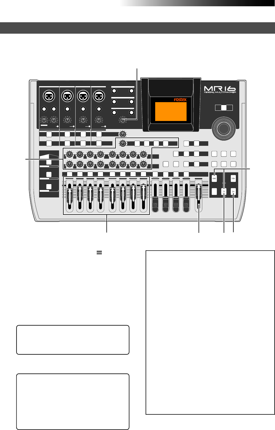
32
MR16 Owner’s Manual (Basic operations)
In the demo song, approximately 1-minute audio is recorded on all eight tracks. Follow the procedure
below for listening to the demo song. In the following procedure, it is assumed that the MR16 is
turned on and a pair of headphones (or a monitor speaker system) is connected.
Playing back the demo song
<Hint-2>: To listen to the demo song again:
When the recorder is stopped after listen-
ing to the demo song, press the [REWIND]
key while holding down the [STOP] key.
The recorder instantly moves back to the
beginning of the demo song (see page 52).
Then pressing the [PLAY] key starts play-
back from the beginning of the demo song.
<Note>:
The demo song is protected and you can-
not overwrite or erase it. Therefore, you cannot
make recording in this condition.
If you want to make new recording while keep-
ing the demo tape on the hard disk, see "Creat-
ing a song for recording" on the next page.
If you do not keep the demo song, carry out ei-
ther of the following operations.
(1) Release the song protection (see page
117).
Then, start recording (overwrite
recording) from the beginning of the demo
song, or delete the demo song from the
hard disk (see page 116). If you delete the
demo song, create a new song (see the next
page) and make recording to the new song.
(2) Format the hard disk (see page 140) and
make recording.
Because a new song is automatically
created after formatting the disk, you can
start recording without the need of
creating a new song manually.
1) Raise the [MASTER] fader to the " " position.
Set the track faders at the lowest position.
2) Press the [PLAY] key to start playback.
3) Raise the track faders (1 through 8) gradually to
adjust the playback level and balance.
Also raise the [PHONES VOL] control gradually
to adjust the headphones level. (If you are
using a powered monitor speaker for
monitoring, adjust the level control of the
powered speaker.)
4) When the demo song ends, press the [STOP] key
to stop the recorder.
<Hint-1>: While listening to the playback
sound, adjust panning setting of tracks 1
through 8, as well as try to adjust the inter-
nal effects (reverb/delay) (see page 70).
PEAK
GUITAR
MIN
DISTORTION
MAX LINE MIC
TRIM
INSERT/GUITAR
UNBAL
BALBALBALBAL
INPUT A INPUT B INPUT C INPUT D
VOLUME
MIN MAX
PEAK
LINE
TRIM
MIC
UNBAL
POWER
UNBAL
MIC
TRIM
LINE
PEAK
UNBAL
MIC
TRIM
LINE
PEAK
MAX
MIN
1
R
L
100
SIMULATION SIMULATION
AMP
MIC
010
LR
010
LR
23
RL
100
4 8
010
LR
7
6
RL
100
RL
100
010
LR
5
MAX
MIN
MASTER
REC SELECT
RECORD STOP PLAY
REWIND F FWD
UNDO/REDO
STORE
LOCATE REC END
LOCATE ABS ZERO
A-B PLAY
BOUNCE
MASTERING
BRIGHT
15/16 > STEREO WAV FILE
NATURAL
POWERFUL
B / OUTA / INPLAY MODEAUTO PUNCH
LOCATE
EFFECT
DELAYPLATEHALLROOM BOUNCE MODE
CONTRAST
TIMEBASE SELECT
RHYTHM GUIDE DIRECT LOCATE
EFFECT SEND
PAN
INPUT EQ
TO STEREO BUSS LEVEL
9/10 11/12 13/14 15/16
ABC1 DEF2 GHI3 JKL4 MNO5 YZ9PQR6 +-_0STU7 VWX8 DELETE
MENU / ENTER
MIN MAX
MIN MAX
REVERB / DELAY TIME
LSTEREO OUT R
1AUX OUT 2
1PHONES 2
DYNAMIC BRIT STACK
CONDENSER US METAL
TUBE 60'S COMBO
INPUT A INPUT B INPUT C INPUT D
12
1,3
3
4
Hint-2
Hint-1
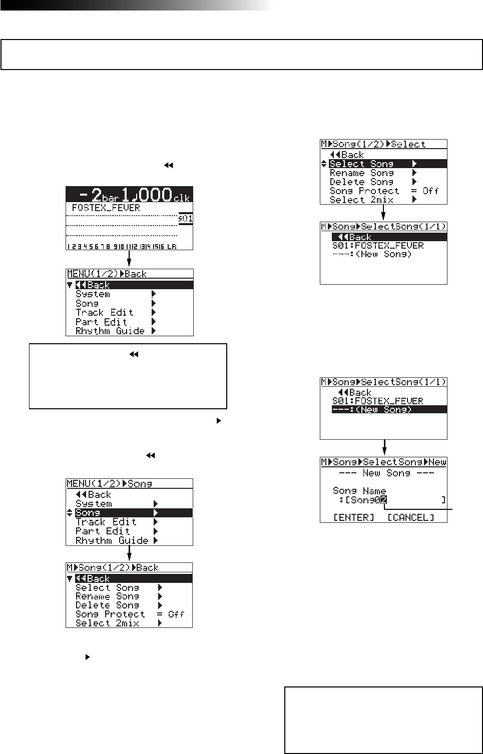
33
MR16 Owner’s Manual (Basic operations)
This section describes how to create a new song for recording on the hard disk, while keeping the
demo song. In the following procedure, it is assumed that the MR16 is stopped at the beginning
(ABS ZERO) of the demo song.
1) While the recorder is stopped, press the
[MENU/ENTER] knob to enter the menu mode.
The display now shows the first page of the
menu selection screen, where " Back" is
highlighted initially.
2) Rotate the [MENU/ENTER] knob to select "Song ",
and press the [MENU/ENTER] knob.
The display now shows the first page of the
song menu screen, where " Back" is
highlighted initially.
3) Rotate the [MENU/ENTER] knob to select
"Select Song ", and press the [MENU/ENTER]
knob.
The display now shows the first page of the
song selection screen. You can see the list of
the song numbers/names on the hard disk.
Currently, only the demo song is created, and
"S01: FOSTEX_FEVER" and "---:(New Song)" are
shown.
"---:(New Song)" is used to create a new song.
4) Rotate the [MENU/ENTER] knob to select
"- - -:(New Song)", and press the [MENU/ENTER]
knob.
5) Enter the desired song name.
<Note>:
By selecting "
Back
" and pressing
the [
MENU/ENTER
] knob, the display returns
to the previous screen. You can also return
the display to the previous screen by press-
ing the [
REWIND
] key.
<Note>:
You may leave the default song
name as it is. Also, you can edit the song
name after creating a song using the "Re-
name Song" menu item in the song menu
of the menu mode (see page 115).
The display now shows the screen for entering
a new song name. The rightmost character on
the default song name is flashing (in the ex-
ample below, "2" of "Song02" starts flashing).
Use the character entry keys to enter the de-
sired character at the flashing point.
Rotate the [MENU/ENTER] knob to move the
flashing point. Use the [DELETE] key to delete
the character at the flashing point. Therefore,
when the rightmost character is flashing as in
the screen example above, you can delete all
characters by pressing the [DELETE] key repeat-
edly. You can enter up to 16 characters for a
song name.
See <How to enter characters> on the next page
for entering the song name as "My_Song".
Creating a song for recording
Flashing
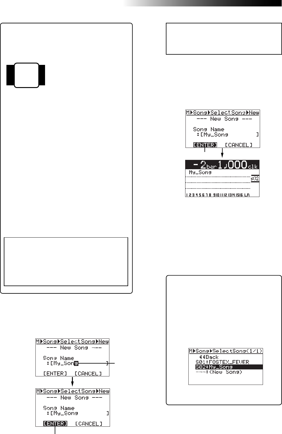
34
MR16 Owner’s Manual (Basic operations)
6) After completing song name entry, press the
[MENU/ENTER] knob.
The cursor moves to “[ENTER]” at the bottom
of the screen.
7) While “[ENTER]” is flashing, press the
[MENU/ENTER] knob.
The display now shows the home screen of the
newly created song (My_Song).
As shown in the lower screen example, the song
name (My_Song) and the song number
(Song02) are shown.
<Note>:
If you want to cancel creating a song,
rotate the [
MENU/ENTER
] knob to move the
cursor to "
[CANCEL]
" and press the [
MENU/
ENTER
] knob.
Now, in addition to the demo song, a new
song on which no audio is recorded is cre-
ated by the procedure above.
It is a good idea to create more than one
song before you start recording.
After creating a song or songs for recording,
connect the sound source to the MR16 (see
the next page) and start recording.
<Character entry keys>
[REC SELECT] keys on the
MR16 top panel act as char-
acter entry keys in the menu
mode.
For example, the [REC SE-
LECT] key for track 1 (shown
on the left) can be used for
entering A, B, C, a, b, c and 1.
<Character entry example>
The following procedure example shows how to en-
ter "My_Song" as a song name.
1. Use the [M N O 5] key to enter "M".
2. Use the [Y Z 9] key to enter "y".
3. Use the [+ _ 0] key to enter "_".
4. Use the [S T U 7] key to enter "S".
5. Use the [M N O 5] key to enter "o".
6. Rotate the [MENU/ENTER] knob to move the
cursor right.
7. Use the [M N O 5] key to enter "n".
8. Use the [G H I 3] key to enter "g".
<Note>:
After creating a new song, by ex-
ecuting procedure steps 1 through 3, the
following song selection screen appears.
This screen is used for loading the desired
song from the list, as well as creating a new
song.
For example, by rotating the [
MENU/ENTER
]
knob to highlight “
S01: FOSTEX_FEVER
” and
pressing the [
MENU/ENTER
] knob, you can
load the demo song.
For details about how to select the desired
song, see "Song management" on page 113.
<How to enter characters>
<Notes on cursor movement>
Pressing a different character entry key automati-
cally moves the cursor right.
If two successive characters are assigned to the
same character entry key, rotate the [
MENU/ENTER
]
knob after selecting the first character to move
the cursor right.
Flashing
Flashing
Flashing
A B C 1
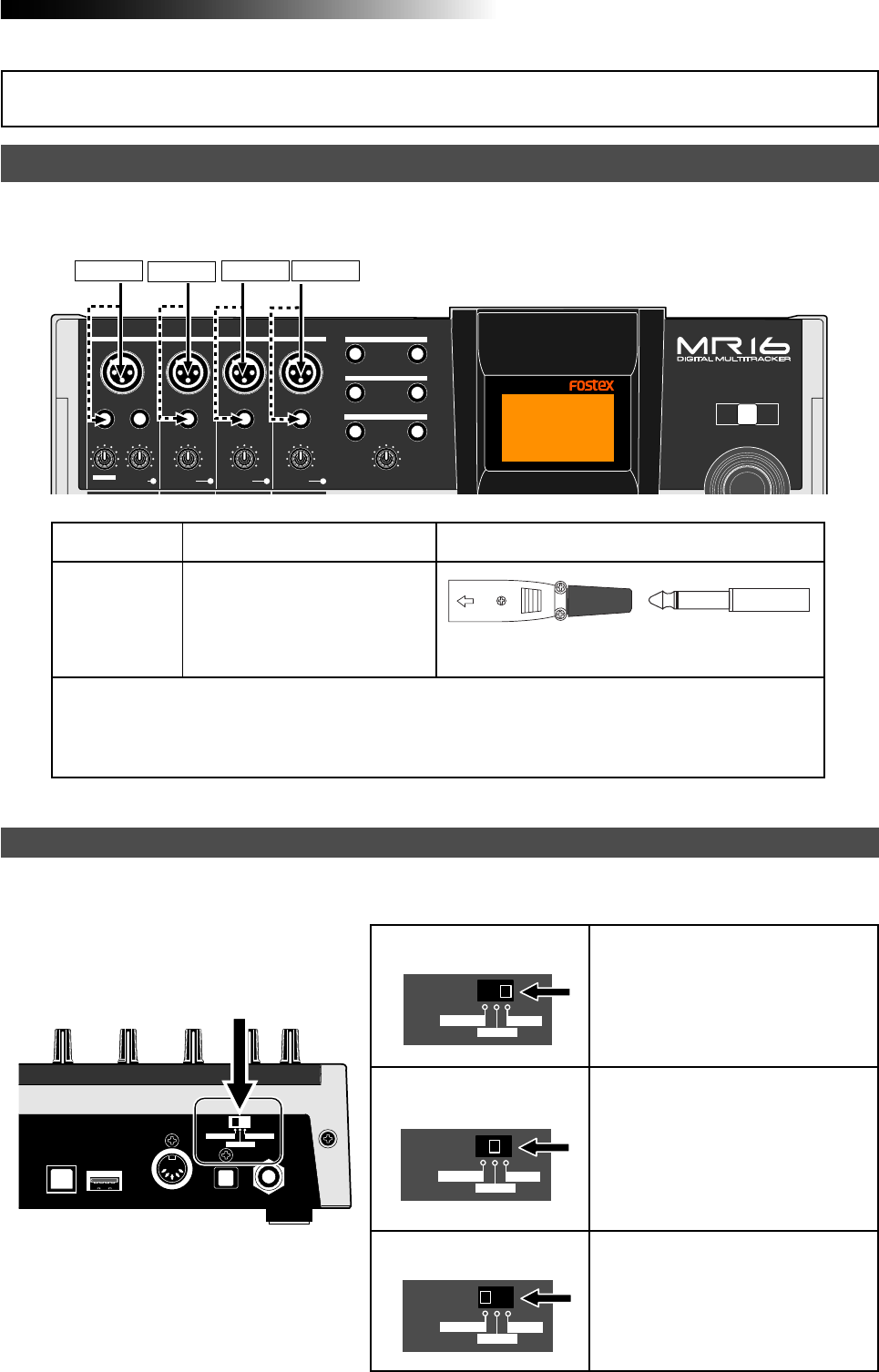
35
MR16 Owner’s Manual (Basic operations)
The MR16 provides four input channels: [INPUT A], [INPUT B], [INPUT C] and [INPUT D].
Each channel provides both the XLR and 1/4" phone connectors.
INPUT A INPUT B INPUT C INPUT D
INPUT A
INPUT B
INPUT C
INPUT D
• When you use the [INPUT A] channel, set the [INPUT A SELECT] switch on the rear panel
appropriately.
• If you use a condenser microphone, use the XLR (balanced) connector.
The MR16 can supply the phantom power (see page 144).
Available input connectors Shapes of connectable connector
Input channel
Either of the XLR (balanced) con-
nector or phone (unbalanced) jack
can be used (if both connectors
are plugged, the phone jack is ef-
fective).
Input channel
When you use the [INPUT A] channel, you must set the [INPUT A SELECT] switch on the rear panel
appropriately.
[INPUT A SELECT] switch
INPUT A SEL
MIC/LINE
GTR CLEAN
GTR DIST
INPUT A SEL
MIC/LINE
GTR CLEAN
GTR DIST
INPUT A SEL
MIC/LINE
GTR CLEAN
GTR DIST
“MIC/LINE” position
“GTR DIST” position
“GTR CLEAN” position
Both the [BAL] XLR and [UNBAL/GUI-
TAR] phone connectors can be used.
Set the switch to this position when the
source is an external microphone or
line level source.
Both the [BAL] XLR and [UNBAL/GUI-
TAR] phone connectors can be used.
You can adjust the input level and dis-
tortion using the [TRIM] and [DISTOR-
TION] controls respectively. You can
also use the amp simulation insert ef-
fect.
Both the [BAL] XLR and [UNBAL/GUI-
TAR] phone connectors can be used.
You can adjust the input level using the
[TRIM] control. You can also use the
amp simulation insert effect.
XLR-3-12C type PHONE plug
PEAK
GUITAR
MIN
DISTORTION
MAX LINE MIC
TRIM
INSERT/GUITAR
UNBAL
BALBALBALBAL
INPUT A INPUT B INPUT C INPUT D
VOLUME
MIN MAX
PEAK
LINE
TRIM
MIC
UNBAL
POWER
UNBAL
MIC
TRIM
LINE
PEAK
UNBAL
MIC
TRIM
LINE
PEAK
LSTEREO OUT R
1AUX OUT 2
1PHONES 2
INPUT A INPUT B INPUT C INPUT D
USB USB HOST MIDI OUT DIGITAL OUT FOOT SW
INPUT A SEL
GTR CLEAN MIC/LINE
GTR DIST
[INPUT A SELECT] switch
Input connection
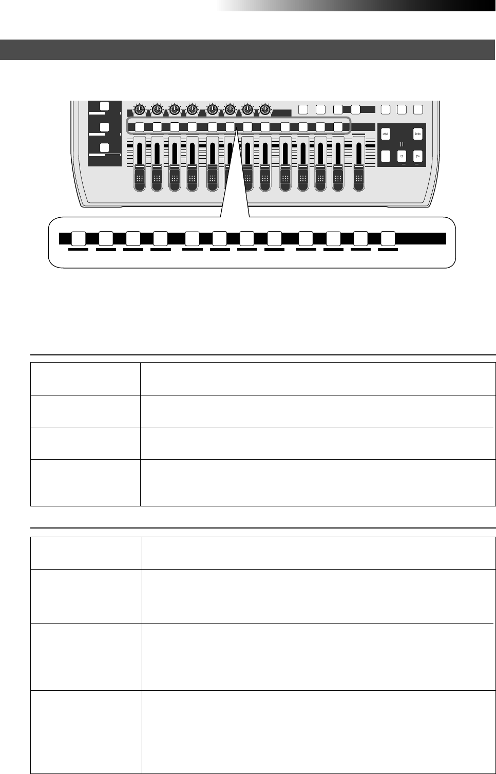
36
MR16 Owner’s Manual (Basic operations)
Recording track combinations and available input channel(s)
The MR16 is a 16-track recorder. Tracks 1 through 8 are mono tracks, while tracks 9 through 16 are
stereo tracks. The [REC SELECT] keys control track arming.
Recording track combinations
With the MR16, you can simultaneously record up to four tracks. Depending on the armed
track(s), the available input channel(s) is (are) automatically assigned.
The following shows the recording track combinations, as well as available input channel(s) by
the number of tracks simultaneously recorded.
MAX
MIN
1
R
LLR LR
23
RL
4 8
LR
7
6
RL
RL
LR
5
MAX
MIN
MASTER
REC SELECT
RECORD STOP PLAY
REWIND F FWD
LOCATE REC END
LOCATE ABS ZERO
A-B PLAY
B / OUTA / INPLAY MODEAUTO PUNCH
LOCATE
CONTRAST
RHYTHM GUIDE DIRECT LOCATE
PAN
9/10 11/12 13/14 15/16
ABC1 DEF2 GHI3 JKL4 MNO5 YZ9PQR6 +-_0STU7 VWX8 DELETE
DYNAMIC BRIT STACK
CONDENSER US METAL
TUBE 60'S COMBO
1234 8
7
6
5
REC SELECT
9/10 11/12 13/14 15/16
ABC1 DEF2 GHI3 JKL4 MNO5 YZ9PQR6 +-_0STU7 VWX8 DELETE
When recording to a single
track
When recording to two
tracks simultaneously
When recording to three
tracks simultaneously
When recording to four
tracks simultaneously
• Any one of tracks 1 through 8.
• Any two of tracks 1 through 8.
• Any pair of tracks 9/10, 11/12, 13/14 and 15/16.
• Any three of tracks 1 through 8
• Any one of tracks 1 through 8 and any pair of tracks 9/10, 11/12, 13/14 and 15/16.
• Any four of tracks 1 through 8
• Any two of tracks 1 through 8 and any pair of tracks 9/10, 11/12, 13/14 and 15/16.
• Any two pairs of tracks 9/10, 11/12, 13/14 and 15/16.
Available input channels
When recording to a single
track
When recording to two
tracks simultaneously
When recording to three
tracks simultaneously
When recording to four
tracks simultaneously
• only [INPUT A] is available.
• [INPUT A] and [INPUT B] are available.
• The [INPUT A] is assigned to the lower numbered track, while the [INPUT B] is
assigned to the higher numbered track.
(Example: Track 1 -> [INPUT A], Track 2 -> [INPUT B])
• [INPUT A], [INPUT B] and [INPUT C] are available.
• The [INPUT A] channel is assigned to the lowest numbered track, the [INPUT B]
channel assigned to the next lower numbered track, and the [INPUT C] channel is
assigned to the highest numbered track .
(Example: INPUT A -> Track 8, INPUT B -> Track 9, INPUT C -> Track 10)
• All input channels ([INPUT A], [INPUT B], [INPUT C] and [INPUT D]) are available.
• The [INPUT A] channel is assigned to the lowest numbered track, the [INPUT B]
channel assigned to the next lower numbered track, the [INPUT C] channel is as
signed to the next higher numbered track, and the [INPUT D] channel is assigned to
the highest numbered track . (Example: INPUT A -> Track 1, INPUT B -> Track 2,
INPUT C -> Track 7, INPUT D -> Track 8)
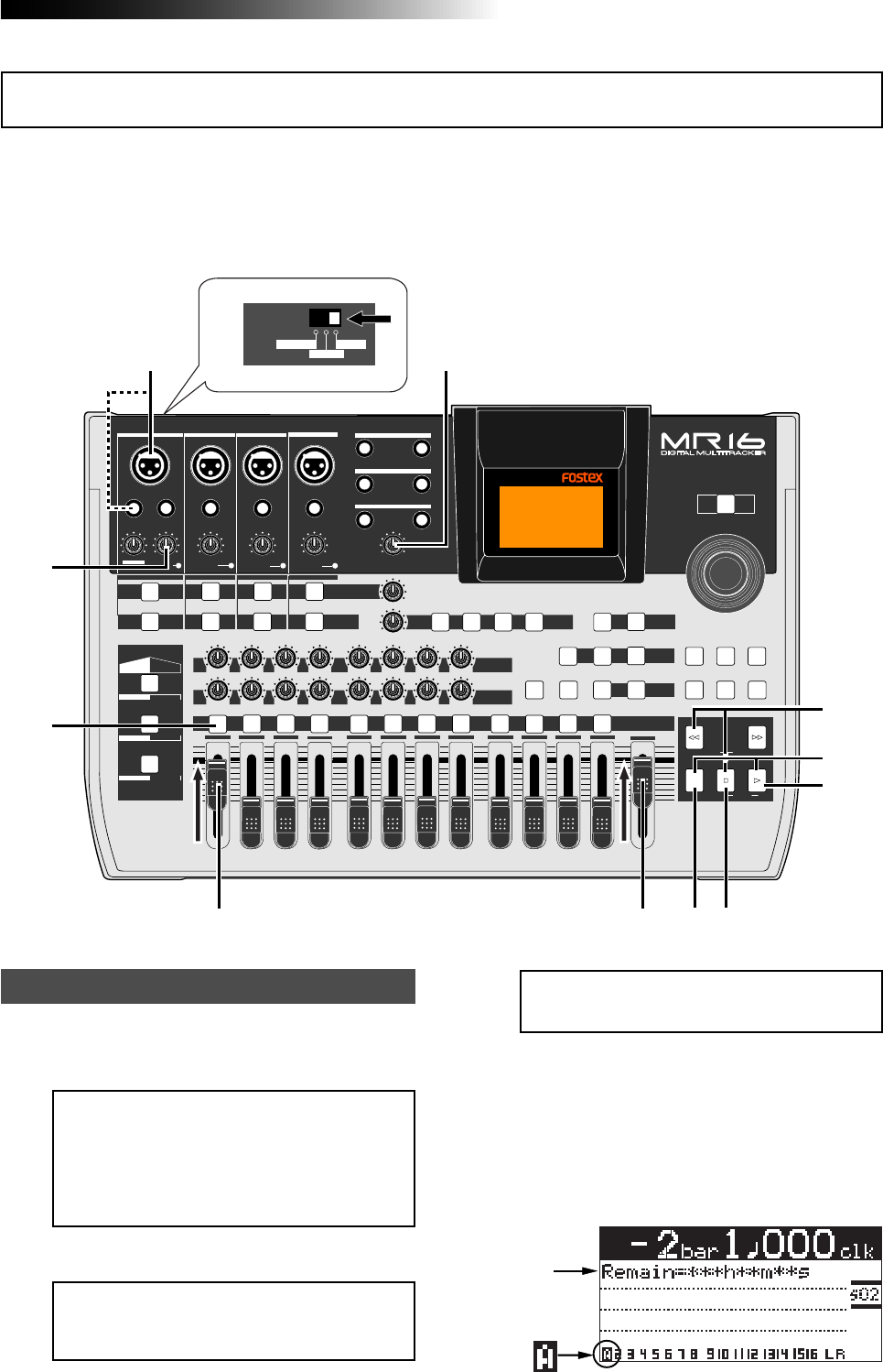
37
MR16 Owner’s Manual (Basic operations)
You can record onto any one of tracks 1 through 8. When making recording to a single track, you
can record a signal fed to the [INPUT A] channel.
The following describes the procedure for recording an acoustic guitar onto track 1 via a micro-
phone. We assume that Song02 is loaded and no sound is recorded to Song02. See "Creating a
song for recording" on page 33 for details about how to create a song.
1) Connect a microphone to the [BAL] or
[UNBAL/GUITAR] input connector of the
[INPUT A] channel.
<Note>:
You can apply the mic simulation
as insert effects when the [
INPUT A SELECT
]
switch to "
MIC/LINE
" (see page 68).
3) Press the [REC SELECT] key for track 1.
Track 1 is record armed and the [REC SELECT]
key for track 1 starts flashing.
On the home screen, the remaining time is
shown, while "1" for the track number changes
to "A". This indicates you can now record the
[INPUT A] channel signals to tracks 1
respectively.
Preparation for recording
2) Set the [INPUT A SELECT] switch to "MIC/LINE".
<Note>:
You can supply the phantom power
to a condenser microphone connected to
the [
BAL
] XLR connector (see page 144).
Note that you cannot supply the phantom
power via the [
GUITAR/UNBAL
] phone con-
nector.
PEAK
GUITAR
MIN
DISTORTION
MAX LINE MIC
TRIM
INSERT/GUITAR
UNBAL
BALBALBALBAL
INPUT A INPUT B INPUT C INPUT D
VOLUME
MIN MAX
PEAK
LINE
TRIM
MIC
UNBAL
POWER
UNBAL
MIC
TRIM
LINE
PEAK
UNBAL
MIC
TRIM
LINE
PEAK
MAX
MIN
1
R
L
100
SIMULATION SIMULATION
AMP
MIC
010
LR
010
LR
23
RL
100
4 8
010
LR
7
6
RL
100
RL
100
010
LR
5
MAX
MIN
MASTER
REC SELECT
RECORD STOP PLAY
REWIND F FWD
UNDO/REDO
STORE
LOCATE REC END
LOCATE ABS ZERO
A-B PLAY
BOUNCE
MASTERING
BRIGHT
15/16 > STEREO WAV FILE
NATURAL
POWERFUL
B / OUTA / INPLAY MODEAUTO PUNCH
LOCATE
EFFECT
DELAYPLATEHALLROOM BOUNCE MODE
CONTRAST
TIMEBASE SELECT
RHYTHM GUIDE DIRECT LOCATE
EFFECT SEND
PAN
INPUT EQ
TO STEREO BUSS LEVEL
9/10 11/12 13/14 15/16
ABC1 DEF2 GHI3 JKL4 MNO5 YZ9PQR6 +-_0STU7 VWX8 DELETE
MENU / ENTER
MIN MAX
MIN MAX
REVERB / DELAY TIME
LSTEREO OUT R
1AUX OUT 2
1PHONES 2
DYNAMIC BRIT STACK
CONDENSER US METAL
TUBE 60'S COMBO
INPUT A INPUT B INPUT C INPUT D
16
6
3
4458
7
9
10
INPUT A SEL
MIC/LINE
GTR CLEAN
GTR DIST
2
Recording onto a single track
<Note>:
You can apply EQ to the input sig-
nal during recording (see page 66).
Remain
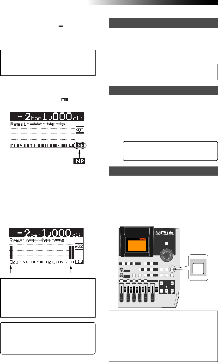
38
MR16 Owner’s Manual (Basic operations)
6) While playing the guitar, adjust the recording level
using the [TRIM] control of the [INPUT A]
channel.
Adjust the level appropriately so that the PEAK
indicator does not light.
Turning the [PHONES VOL] control clockwise
raises the headphone monitor level.
The screen shows the input level of track 1, as
well as the stereo L and R output levels.
<Note>:
The fader for track 1 is used to ad-
just the monitor level. To adjust the record-
ing level, use the [
TRIM
] control of the [
IN-
PUT A
] channel.
<Note>:
Adjust the [
TRIM
] control properly
so that the PEAK indicator does not light at
the loudest part of the guitar sound. If the
input level is too high, the PEAK indicator
lights and the sound may be distorted or
noisy.
<Tip>: When receiving a line level signal, set
the [TRIM] control to left ("LINE") to get the
appropriate level. When receiving a micro-
phone signal, set the [TRIM] control to right
("MIC") to get the appropriate level.
7) While holding down the [RECORD] key, press the
[PLAY] key to start recording.
The guitar is recorded.
8) When recording completes, press the [STOP] key
to stop the recorder.
<Note>:
We recommend to press the [
REC
SELECT
] key for track 1 to unarm track 1.
Starting recording
9) Press the [REWIND] key while holding down the
[STOP] key to locate the recorder to the
beginning of the song.
10) Press the [PLAY] key to start playback.
You can adjust the monitor level using the track
1 fader, as well as the [MASTER] fader and
[PHONES VOL] control.
Playing back the recorded track
If you are not satisfied with the result, use
the undo/redo function to cancel the re-
cording and try again.
Undoing recording (undo/redo)
5) Press the [RECORD] key once (the key indicator
starts flashing).
Track 1 (which is record armed) now enters
the input monitor mode and " " is shown on
the home screen.
If you press the [UNDO/REDO] key after finishing
recording, you can return to the condition before
the recording started (UNDO operation). Therefore,
you can try recording again.
If you press the [UNDO/REDO] key again (after
UNDO), the undo operation is canceled and you
can return to the condition when the recording
finished (REDO operation).
<Notes>:
The undo/redo function is available for
all kind of recordings, however, if you carry out
any of the following operations after making re-
cording, you cannot undo the recording.
• Carrying out new recording.
• Carrying out track or part editing.
• Turning off the power.
• Selecting another song or editing the song name.
[UNDO/REDO] key
4) Set track fader 1 and [MASTER] fader to the
nominal position (marked by ).
Raising these faders allows you to monitor the
input sound. If these faders are not raised, you
cannot monitor the sound via headphones.
POWER
8
010
LR
MAX
MIN
MASTER
REC SELECT
RECORD STOP PLAY
REWIND F FWD
UNDO/REDO
STORE
LOCATE REC END
LOCATE ABS ZERO
A-B PLAY
BOUNCE
MASTERING
BRIGHT
15/16 > STEREO WAV FILE
NATURAL
POWERFUL
B / OUTA / INPLAY MODEAUTO PUNCH
LOCATE
EFFECT
DELAYPLATEHALL BOUNCE MODE
CONTRAST
TIMEBASE SELECT
RHYTHM GUIDE DIRECT LOCATE
EFFECT SEND
PAN
9/10 11/12 13/14 15/16
YZ9 +-_0VWX8 DELETE
MENU / ENTER
UNDO/REDO
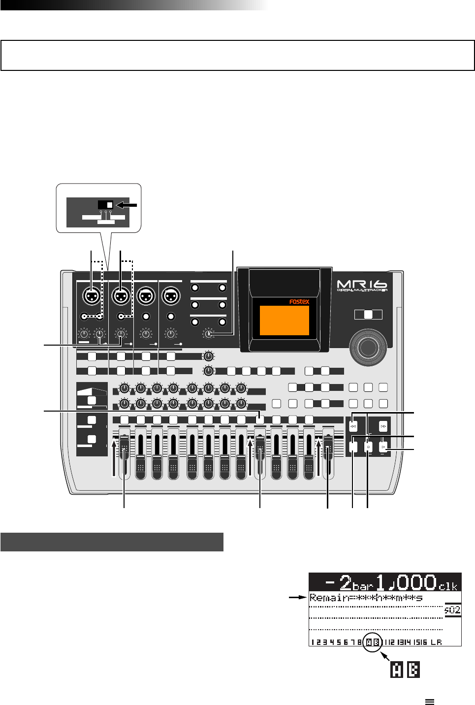
39
MR16 Owner’s Manual (Basic operations)
Overdubbing is recording something new while listening to the previously recorded track(s).
It is a very important method in multitrack recording. The following describes an example of
overdubbing for recording a stereo keyboard to tracks 9/10 while listening to the guitar on track
1. See the procedure previously described in "Recording onto a single track" for details about how
to record a guitar on track 1. In the procedure below, we assume that the song of which the
guitar has been recorded on track 1 is loaded.
Note that you can make overdubbing to another track or other tracks in the same manner as
described below.
1) Connect the L and R outputs of the keyboard to
input connectors of the [INPUT A] and [INPUT B]
channels.
Connect the L and R outputs to the [INPUT A]
and [INPUT B] channels respectively.
2) Set the [INPUT A SELECT] switch to "MIC/LINE".
3) Press the [REC SELECT] key for tracks 9/10.
Tracks 9/10 are record armed and the
[REC SELECT] key for tracks 9/10 starts
flashing.
On the home screen, the remaining time is
shown, while "9" and "10" for the track
numbers change to "A" and "B" respectively.
Preparation for recording
4) Set track faders 1 and 7/8 and the [MASTER] fader
to the nominal position (marked by ).
Raising these faders allows you to monitor the
input sound. If these faders are not raised, you
cannot monitor the sound via headphones.
This indicates you can now record the [INPUT
A] and [INPUT B] channel signals to tracks 9
and 10 respectively.
PEAK
GUITAR
MIN
DISTORTION
MAX LINE MIC
TRIM
INSERT/GUITAR
UNBAL
BALBALBALBAL
INPUT A INPUT B INPUT C INPUT D
VOLUME
MIN MAX
PEAK
LINE
TRIM
MIC
UNBAL
POWER
UNBAL
MIC
TRIM
LINE
PEAK
UNBAL
MIC
TRIM
LINE
PEAK
MAX
MIN
1
R
L
100
SIMULATION SIMULATION
AMP
MIC
010
LR
010
LR
23
RL
100
4 8
010
LR
7
6
RL
100
RL
100
010
LR
5
MAX
MIN
MASTER
REC SELECT
RECORD STOP PLAY
REWIND F FWD
UNDO/REDO
STORE
LOCATE REC END
LOCATE ABS ZERO
A-B PLAY
BOUNCE
MASTERING
BRIGHT
15/16 > STEREO WAV FILE
NATURAL
POWERFUL
B / OUTA / INPLAY MODEAUTO PUNCH
LOCATE
EFFECT
DELAYPLATEHALLROOM BOUNCE MODE
CONTRAST
TIMEBASE SELECT
RHYTHM GUIDE DIRECT LOCATE
EFFECT SEND
PAN
INPUT EQ
TO STEREO BUSS LEVEL
9/10 11/12 13/14 15/16
ABC1 DEF2 GHI3 JKL4 MNO5 YZ9PQR6 +-_0STU7 VWX8 DELETE
MENU / ENTER
MIN MAX
MIN MAX
REVERB / DELAY TIME
LSTEREO OUT R
1AUX OUT 2
1PHONES 2
DYNAMIC BRIT STACK
CONDENSER US METAL
TUBE 60'S COMBO
INPUT A INPUT B INPUT C INPUT D
17
7
3
44 5 8,10
8,11
9
6,12
1
4
INPUT A SEL
MIC/LINE
GTR CLEAN
GTR DIST
2
Overdubbing basics
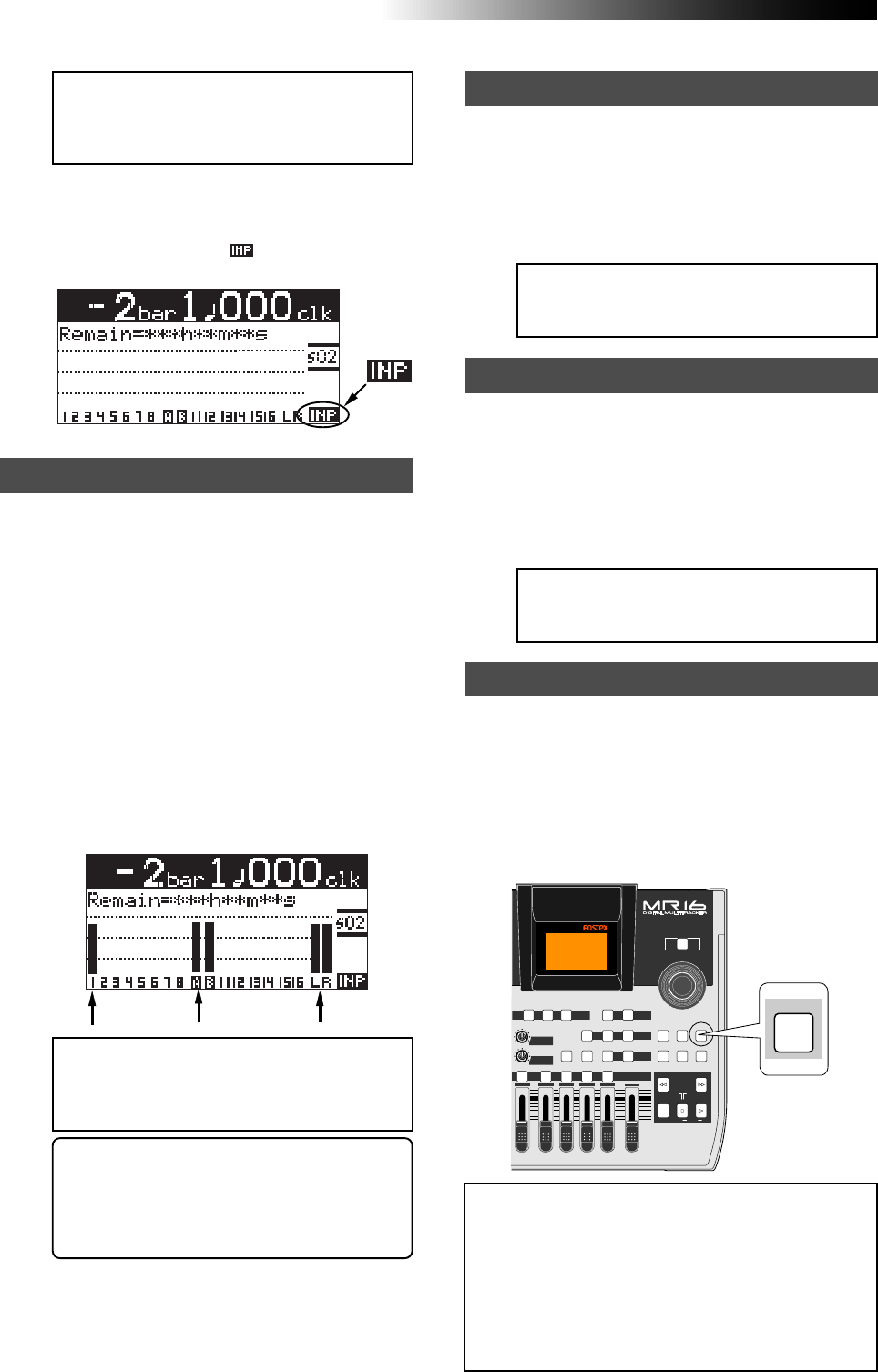
40
MR16 Owner’s Manual (Basic operations)
9) While holding down the [RECORD] key, press the
[PLAY] key to start recording.
The recorder records the keyboard while
playing back track 1 (guitar).
10) When recording completes, press the [STOP] key
to stop the recorder.
<Note>:
We recommend to press the
[
REC SELECT
] key for tracks 9/10 to unarm
tracks 9/10.
Starting recording
11) Press the [REWIND] key while holding down the
[STOP] key to locate the recorder to the
beginning of the song.
12) Press the [PLAY] key to start playback.
You can adjust the monitor level using the track
faders, as well as the [MASTER] fader and
[PHONES VOL] control.
Playing back the recorded track
<Note>:
If you are not satisfied with the re-
sult, use the undo/redo function to cancel
the recording and try again.
Undoing recording (undo/redo)
If you press the [UNDO/REDO] key after finishing
recording, you can return to the condition before
the recording started (UNDO operation). Therefore,
you can try recording again.
If you press the [UNDO/REDO] key again (after
UNDO), the undo operation is canceled and you
can return to the condition when the recording
finished (REDO operation).
<Notes>:
The undo/redo function is available for
all kind of recordings, however, if you carry out
any of the following operations after making re-
cording, you cannot undo the recording.
• Carrying out new recording.
• Carrying out track or part editing.
• Turning off the power.
• Selecting another song or editing the song name.
[UNDO/REDO] key
<Note>:
Track 1 and 9/10 faders are used
to adjust the monitor level. To adjust the
recording levels, use the [
TRIM
] controls of
the [
INPUT A
] and [
INPUT B
] channels.
<Note>:
Adjust each [
TRIM
] control properly
so that the corresponding PEAK indicator
does not light at the loudest part of the key-
board sound.
<Tip>: When receiving a line level signal, set
the [TRIM] control to left ("LINE") to get the
appropriate level. When receiving a micro-
phone signal, set the [TRIM] control to right
("MIC") to get the appropriate level.
5) Press the [RECORD] key once (the key indicator
starts flashing).
The armed tracks 9/10 now enter the input
monitor mode, while " " is shown on the
home screen.
Adjusting the recording levels while listening to track 1
6) Press the [PLAY] key to play back the song from
the beginning.
Though tracks 9/10 are in the input monitor
mode, you can hear the track 1 signal by
rotating the [PHONES VOL] control clockwise
(while the meter for track 1 shows the
playback level).
7) While playing the keyboard, adjust the recording
levels using the [TRIM] controls of the [INPUT A]
and [INPUT B] channels.
Adjust the levels appropriately so that the PEAK
indicators for these input channels do not light.
The home screen shows the playback level of
track 1 and the input levels of tracks 9 and 10,
as well as the stereo L and R output levels.
8) After adjusting the recording levels properly,
press the [REWIND] key while holding down the
[STOP] key to locate the recorder to the
beginning of the song.
POWER
8
010
LR
MAX
MIN
MASTER
REC SELECT
RECORD STOP PLAY
REWIND F FWD
UNDO/REDO
STORE
LOCATE REC END
LOCATE ABS ZERO
A-B PLAY
BOUNCE
MASTERING
BRIGHT
15/16 > STEREO WAV FILE
NATURAL
POWERFUL
B / OUTA / INPLAY MODEAUTO PUNCH
LOCATE
EFFECT
DELAYPLATEHALL BOUNCE MODE
CONTRAST
TIMEBASE SELECT
RHYTHM GUIDE DIRECT LOCATE
EFFECT SEND
PAN
9/10 11/12 13/14 15/16
YZ9 +-_0VWX8 DELETE
MENU / ENTER
UNDO/REDO
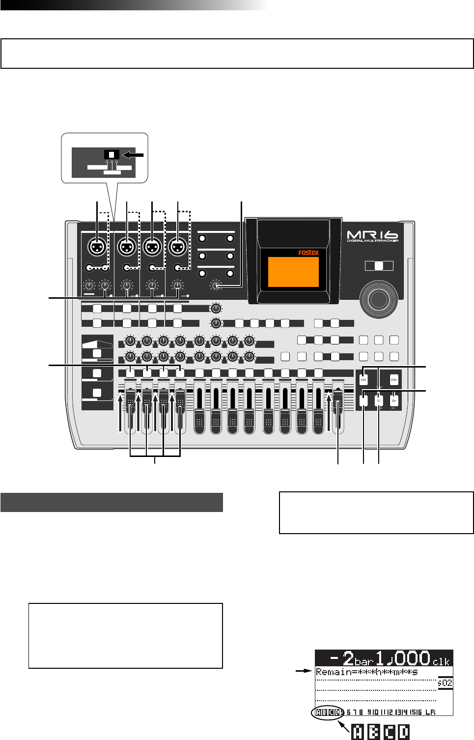
41
MR16 Owner’s Manual (Basic operations)
You can simultaneously record up to four tracks. See page 36 for the available combinations of
four recording tracks. The following describes the procedure for recording different sound sources
simultaneously to tracks 1 through 4. You can make four-track simultaneous recording with any
available track combination in the same manner.
1) Connect the following sound sources to the
[INPUT A] through [INPUT D] channels.
[INPUT A] -> Electric guitar
[INPUT B] -> Electric bass
[INPUT C] -> Microphone (vocal)
[INPUT D] -> Drum machine
Preparation for recording
PEAK
GUITAR
MIN
DISTORTION
MAX LINE MIC
TRIM
INSERT/GUITAR
UNBAL
BALBALBALBAL
INPUT A INPUT B INPUT C INPUT D
VOLUME
MIN MAX
PEAK
LINE
TRIM
MIC
UNBAL
POWER
UNBAL
MIC
TRIM
LINE
PEAK
UNBAL
MIC
TRIM
LINE
PEAK
MAX
MIN
1
R
L
100
SIMULATION SIMULATION
AMP
MIC
010
LR
010
LR
23
RL
100
4 8
010
LR
7
6
RL
100
RL
100
010
LR
5
MAX
MIN
MASTER
REC SELECT
RECORD STOP PLAY
REWIND F FWD
UNDO/REDO
STORE
LOCATE REC END
LOCATE ABS ZERO
A-B PLAY
BOUNCE
MASTERING
BRIGHT
15/16 > STEREO WAV FILE
NATURAL
POWERFUL
B / OUTA / INPLAY MODEAUTO PUNCH
LOCATE
EFFECT
DELAYPLATEHALLROOM BOUNCE MODE
CONTRAST
TIMEBASE SELECT
RHYTHM GUIDE DIRECT LOCATE
EFFECT SEND
PAN
INPUT EQ
TO STEREO BUSS LEVEL
9/10 11/12 13/14 15/16
ABC1 DEF2 GHI3 JKL4 MNO5 YZ9PQR6 +-_0STU7 VWX8 DELETE
MENU / ENTER
MIN MAX
MIN MAX
REVERB / DELAY TIME
LSTEREO OUT R
1AUX OUT 2
1PHONES 2
DYNAMIC BRIT STACK
CONDENSER US METAL
TUBE 60'S COMBO
INPUT A INPUT B INPUT C INPUT D
16
6
3
445
8
9
7
1
INPUT A SEL
MIC/LINE
GTR CLEAN
GTR DIST
2
11
<Note>:
You can apply the amp simulation
as insert effects when the [
INPUT A SELECT
]
switch is set to "
GTR DIST
" (see page 68).
<Note>:
If you connect a condenser micro-
phone to the [
BAL
] XLR connector of the [
IN-
PUT C
] channel, you can supply the phan-
tom power to the microphone (see page
144).
2) Set the [INPUT A SELECT] switch to "GTR DIST".
You can add distortion of the internal effects
to your guitar sound.
3) Press the [REC SELECT] key for tracks 1 through 4.
Tracks 1 through 4 are record armed and the
[REC SELECT] keys for tracks 1 through 4 start
flashing.
On the home screen, track numbers "1"
through "4" changes to "A" through "D"
respectively, showing that each input is
assigned to the appropriate track.
The remaining time of the hard disk is shown.
Recording onto four tracks simultaneously
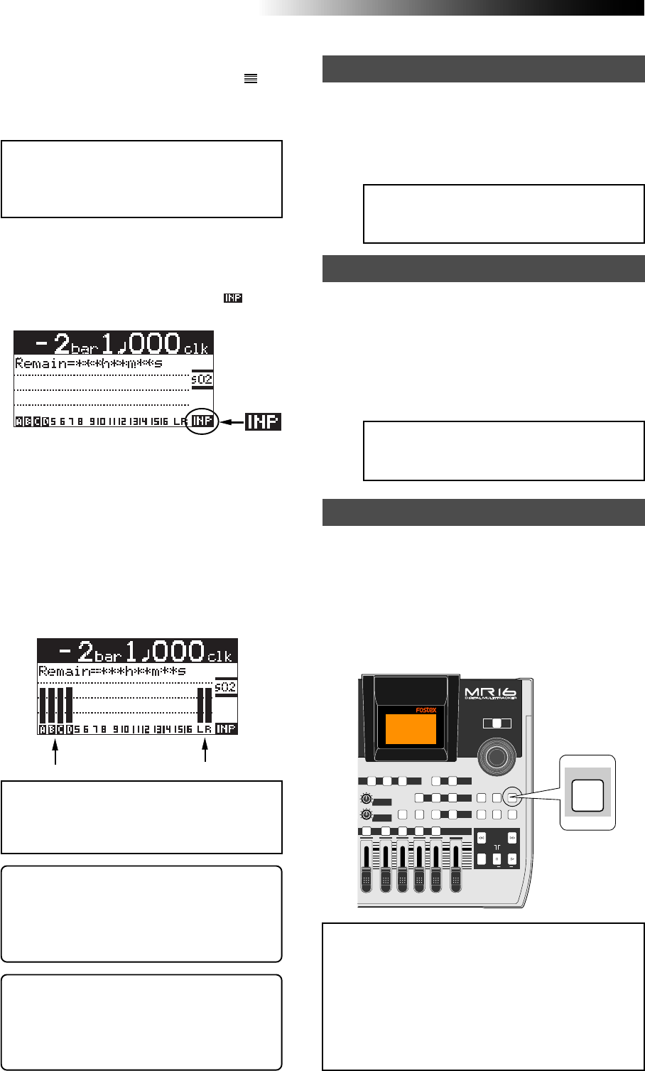
42
MR16 Owner’s Manual (Basic operations)
6) While playing the music, adjust the recording
level of each track using the [TRIM] control of
each input channel.
Adjust the level appropriately so that the PEAK
indicator does not light.
Turning the [PHONES VOL] control clockwise
raises the headphone monitor level.
The screen shows the input level of tracks 1
through 4, as well as the stereo L and R output
levels.
<Note>:
Track faders 1 through 4 are used
to adjust the monitor levels. To adjust the
recording level, use the [
TRIM
] controls for
[
INPUT A
] through [
INPUT D
].
<Note>:
Adjust the [
TRIM
] control of each
input channel properly so that the PEAK
indicator does not light at the loudest part
of the sound.
<Tip>: When receiving a line level signal, set
the [TRIM] control to left ("LINE") to get the
appropriate level. When receiving a micro-
phone signal, set the [TRIM] control to right
("MIC") to get the appropriate level.
7) While holding down the [RECORD] key, press the
[PLAY] key to start recording.
The recorder starts recording.
8) When recording completes, press the [STOP] key
to stop the recorder.
<Note>:
We recommend to press the [
REC
SELECT
] key for tracks 1 through 4 to un-
arm these tracks.
Starting recording
9) Press the [REWIND] key while holding down the
[STOP] key to locate the recorder to the
beginning of the song.
10) Press the [PLAY] key to start playback.
You can adjust the monitor level using track
faders 1 through 4, as well as the [MASTER]
fader and [PHONES VOL] control.
Playing back the recorded track
<Note>:
If you are not satisfied with the re-
sult, use the undo/redo function to cancel
the recording and try again.
Undoing recording (undo/redo)
5) Press the [RECORD] key once (the key indicator
starts flashing).
Tracks 1 through 4 (which are armed) now
enter the input monitor mode and " " is
shown on the home screen.
If you press the [UNDO/REDO] key after finishing
recording, you can return to the condition before
the recording started (UNDO operation). Therefore,
you can try recording again.
If you press the [UNDO/REDO] key again (after
UNDO), the undo operation is canceled and you
can return to the condition when the recording
finished (REDO operation).
<Notes>:
The undo/redo function is available for
all kind of recordings, however, if you carry out
any of the following operations after making re-
cording, you cannot undo the recording.
• Carrying out new recording.
• Carrying out track or part editing.
• Turning off the power.
• Selecting another song or editing the song name.
[UNDO/REDO] key
<Tip>: You can add distortion to an electric
guitar connected to [INPUT A]. Use the [DIS-
TORTION] control to adjust the distortion
level. When you add distortion, readjust the
[TRIM] control.
4) Set the track faders 1 through 4 and [MASTER]
fader to the nominal position (marked by ).
Raising these faders allows you to monitor the
input sound. If these faders are not raised, you
cannot monitor the sound via headphones.
POWER
8
010
LR
MAX
MIN
MASTER
REC SELECT
RECORD STOP PLAY
REWIND F FWD
UNDO/REDO
STORE
LOCATE REC END
LOCATE ABS ZERO
A-B PLAY
BOUNCE
MASTERING
BRIGHT
15/16 > STEREO WAV FILE
NATURAL
POWERFUL
B / OUTA / INPLAY MODEAUTO PUNCH
LOCATE
EFFECT
DELAYPLATEHALL BOUNCE MODE
CONTRAST
TIMEBASE SELECT
RHYTHM GUIDE DIRECT LOCATE
EFFECT SEND
PAN
9/10 11/12 13/14 15/16
YZ9 +-_0VWX8 DELETE
MENU / ENTER
UNDO/REDO
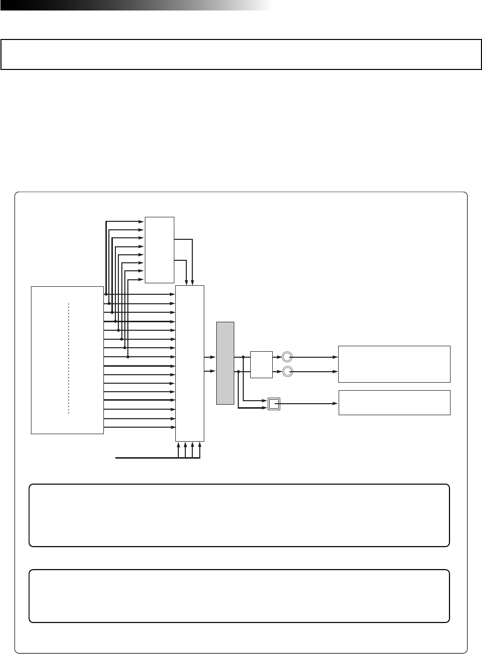
43
MR16 Owner’s Manual (Basic operations)
This section describes basic mixdown which is the final process of multitrack recording. Mixdown
mixes recorded materials on tracks 1 through 16 down to stereo. The mixdowned material can
be recorded to an external master recorder.
The MR16 is equipped with the [DIGITAL OUT] connector, so you can record a mixdowned signal
to a digital master recorder (DAT, MD, etc.) which can accept an S/P DIF digital signal in digital
domain. With the MR16, you can also record a mixdowned signal internally to a new song of the
MR16 using the track bouncing function, without the need of an external master recorder (see
"Track bouncing" described later).
Basic mixdown
Track 1
Mixing
Delay
or
Reverb
playback
INPUT A ~ INPUT D
Track 16
STEREO OUT L, R
D/A
DIGITAL OUT
Analog Master Recorder
Analog Master Recorder
playback
Mastering Effect
<Tips>: When you mix down to an external (digital or analog) master recorder, you can
apply the internal effects (reverb/delay) to playback tracks 1 through 8 or apply the
mastering effects to the stereo mix signals.
For details about the internal effect and mastering effects, see page 65.
<Tips>: When you mix down to an external (digital or analog) master recorder, you can
mix sounds from inputs A through D to the sounds from tracks 1 through 16.
For details about how to mix sounds from inputs A through D, see page 85.
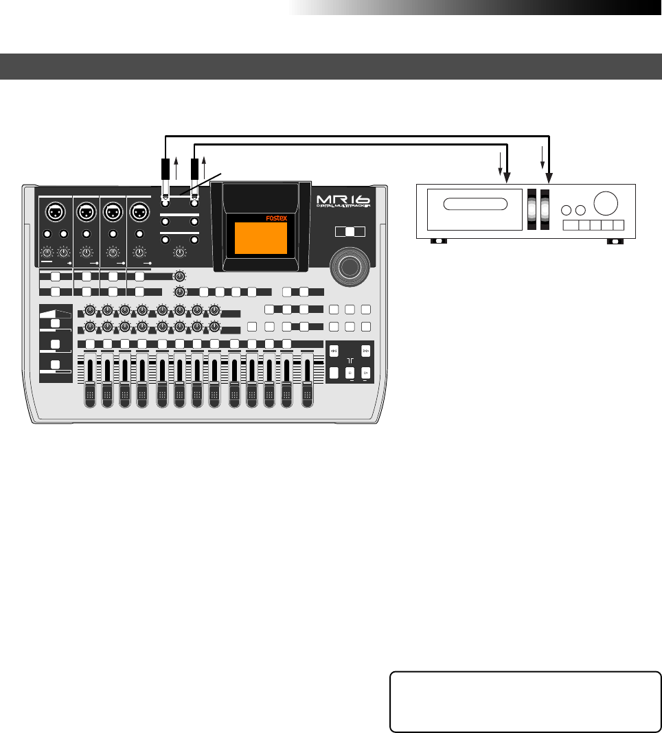
44
MR16 Owner’s Manual (Basic operations)
<Tip>: By sliding up or down the MR16
[MASTER] fader gradually, you can fade in
or fade out recording.
3) Adjust the recording level of the master recorder
while rehearsing mixdown.
See the manual of the master recorder for
details about how to adjust the recording level.
4) After rehearsing mixdown and adjusting the
recording level, locate the MR16 to the beginning
of the song.
5) Start the master recorder recording and then start
the MR16 playing back.
6) After finishing recording, stop both recorders.
1) Connect the [STEREO OUT (L, R)] connectors of
the MR16 to the input connectors of an analog
master recorder.
2) While playing back the MR16, rehearse mixing
down the recorded sounds by adjusting the level
and panning of each track, applying effects to
tracks 1 through 8 and applying the mastering
effects to the L/R stereo mix, etc.
The output levels from the [STEREO OUT (L,
R)] connectors can be controlled by the
[MASTER] fader.
Adjust the levels appropriately so that the
highest segments of L and R meters do not light.
See "Using effects" on page 65 for details about
the delay/reverb and mastering effects.
You can also mix sound sources connected to
[INPUT A] through [INPUT D] during mixdown.
See page 85 for details.
The following describes how to make mixdown recording to an external analog recorder.
PEAK
GUITAR
MIN
DISTORTION
MAX LINE MIC
TRIM
INSERT/GUITAR
UNBAL
BALBALBALBAL
INPUT A INPUT B INPUT C INPUT D
VOLUME
MIN MAX
PEAK
LINE
TRIM
MIC
UNBAL POWER
UNBAL
MIC
TRIM
LINE
PEAK
UNBAL
MIC
TRIM
LINE
PEAK
MAX
MIN
1
R
L
100
SIMULATION SIMULATION
AMP
MIC
010
LR
010
LR
23
RL
100
4 8
010
LR
7
6
RL
100
RL
100
010
LR
5
MAX
MIN
MASTER
REC SELECT
RECORD STOP PLAY
REWIND F FWD
UNDO/REDO
STORE
LOCATE REC END
LOCATE ABS ZERO
A-B PLAY
BOUNCE
MASTERING
BRIGHT
15/16 > STEREO WAV FILE
NATURAL
POWERFUL
B / OUTA / INPLAY MODEAUTO PUNCH
LOCATE
EFFECT
DELAYPLATEHALLROOM BOUNCE MODE
CONTRAST
TIMEBASE SELECT
RHYTHM GUIDE DIRECT LOCATE
EFFECT SEND
PAN
INPUT EQ
TO STEREO BUSS LEVEL
9/10 11/12 13/14 15/16
ABC1 DEF2 GHI3 JKL4 MNO5 YZ9PQR6 +-_0STU7 VWX8 DELETE
MENU / ENTER
MIN MAX
MIN MAX
REVERB / DELAY TIME
LSTEREO OUT R
1AUX OUT 2
1PHONES 2
DYNAMIC BRIT STACK
CONDENSER US METAL
TUBE 60'S COMBO
INPUT A INPUT B INPUT C INPUT D
Analog master recorder
Mixdown to an analog recorder
[STEREO OUT L, R]
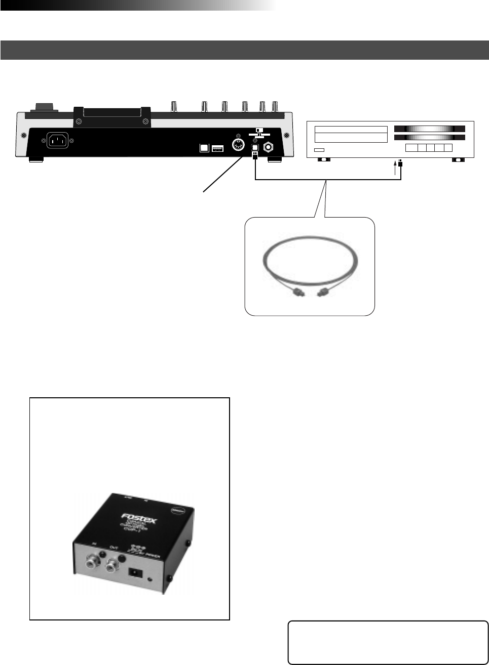
45
MR16 Owner’s Manual (Basic operations)
1) Connect the [DIGITAL OUT] connector of the
MR16 to the digital input connector of a digital
master recorder using an optical cable.
<Note>:
The [
DIGITAL OUT
] connector of the
MR16 is the Toslink optical type.
If your digital recorder provides only the
coaxial type connector, use the Fostex COP-
1/96kHz coaxial-optical converter.
Contact Fostex or our dealer for details
about the Model COP-1/96kHz.
The following describes how to make mixdown recording to an external digital recorder.
<Tip>: By sliding up or down the MR16
[MASTER] fader gradually, you can fade in
or fade out recording.
USB USB HOST MIDI OUT DIGITAL OUT FOOT SW
INPUT A SEL
GTR CLEAN MIC/LINE
GTR DIST
Digital master recorder
Mixdown to a digital recorder
Optical cable
2) Set the master recorder to accept the digital
input.
Make sure that the recorder accepts the digital
signal output from the MR16, which is
44.1-kHz, 16-bit, S/P DIF signal.
Generally, a digital recorder cannot adjust the
digital input level.
3) While playing back the MR16, rehearse mixing
down the recorded sounds by adjusting the level
and panning of each track, applying effects to
tracks 1 through 8 and applying the mastering
effects to the L/R stereo mix, etc.
See "Using effects" on page 65 for details about
the delay/reverb and mastering effects.
You can also mix sound sources connected to
[INPUT A] through [INPUT D] during mixdown.
See page 85 for details.
4) Use the [MASTER] fader of the MR16 to adjust
the output level.
Adjust the level appropriately so that the level
meter of the master recorder shows "0" when
the MR16 outputs the biggest signal.
If the level meter exceeds "0", the sound may
be distorted.
5) Start the master recorder recording and then start
the MR16 playing back.
6) After finishing recording, stop both recorders.
[DIGITAL OUT]
Model COP-1/96kHz

46
MR16 Owner’s Manual (Basic operations)

47
MR16 Owner’s Manual (Advanced playback and locate functions)
Advanced playback and locate functions
This chapter describes advanced playback functions including cueing,
partial playback (between points A and B), special play modes, as well as
the locate function.
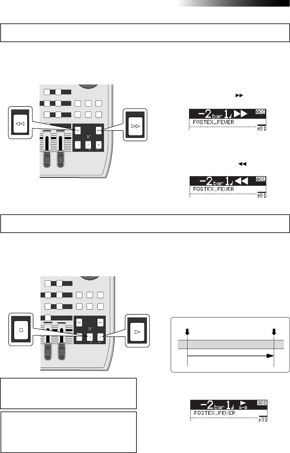
48
MR16 Owner’s Manual (Advanced playback and locate functions)
• By holding down the [F FWD] key during play
back, the recorder starts cueing forwards at 3 x
speed.
During forward cueing, " " is shown on the
display.
• By holding down the [REWIND] key during play
back, the recorder starts cueing backwards at 3
x speed.
During backward cueing, " " is shown on the
display.
When the LOCATE A and LOCATE B points are set, you can playback between these points once.
This function is always available regardless of the play mode setting (see "Play mode" on next
page). This function allows you to check the editing part (between LOCATE A and B points) for
copy/paste, erase, etc. See "Part editing" described later.
By holding down the [F FWD] or [REWIND] key during playback, the recorder enters cueing mode
and you can monitor playback at 3 x speed. It may be useful for searching a specific position.
• While the recorder is stopped, press the [PLAY]
key while holding down the [STOP] key.
The MR16 plays back audio data between the
LOCATE A and LOCATE B points once, then
stops.
<Note>:
If you carry out the operation above when
the LOCATE A point is set ahead of the LOCATE B
point (i.e. LOCATE A > LOCATE B), the MR16 plays
back audio data from the LOCATE A point to the
REC END points once, then stops.
<Note>:
Note that this function is available only
when the LOCATE A and B points are set.
See page 53 for details about how to set the LO-
CATE A and B points.
LOCATE A point
Playback
LOCATE B point
During playback, you can monitor playback
audio of the desired track(s) by raising the ap-
propriate track fader(s), the [MASTER] fader
and the [PHONES] control.
While the recorder is playing back between the
LOCATE A and B points, the display shows the
icon as below.
[REWIND] key [F FWD] key
[STOP] key [PLAY] key
3 x cueing
Playback between LOCATE A and B points
MAX
MIN
MASTER
REC SELECT
RECORD STOP PLAY
REWIND F FWD
UNDO/REDO
STORE
LOCATE REC END
LOCATE ABS ZERO
A-B PLAY
BOUNCE
MASTERING
BRIGHT
15/16 > STEREO WAV FILE
NATURAL
B / OUTA / IN
LOCATE
BOUNCE MODE
CONTRAST
TIMEBASE SELECT
RHYTHM GUIDE DIRECT LOCATE
15/16
DELETE
MENU / ENTER
F FWD
REWIND
MAX
MIN
MASTER
REC SELECT
RECORD STOP PLAY
REWIND F FWD
UNDO/REDO
STORE
LOCATE REC END
LOCATE ABS ZERO
A-B PLAY
BOUNCE
MASTERING
BRIGHT
15/16 > STEREO WAV FILE
NATURAL
B / OUTA / IN
LOCATE
BOUNCE MODE
CONTRAST
TIMEBASE SELECT
RHYTHM GUIDE DIRECT LOCATE
15/16
DELETE
MENU / ENTER
PLAY
STOP
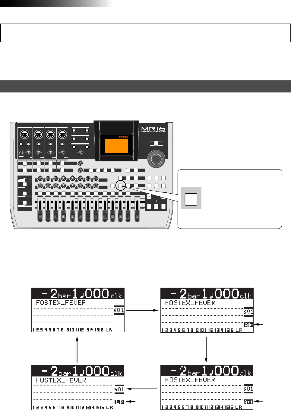
49
MR16 Owner’s Manual (Advanced playback and locate functions)
The current mode is shown on the screen as follows (when "Off" is selected, there is
no indication).
The MR16 offers special play modes including the auto play, auto return and loop playback
modes in addition to the normal playback mode.
Selecting a play mode
<Play mode "off"> <Auto play mode>
<Auto return mode>
<Loop mode>
PEAK
GUITAR
MIN
DISTORTION
MAX LINE MIC
TRIM
INSERT/GUITAR
UNBAL
BALBALBALBAL
INPUT A INPUT B INPUT C INPUT D
VOLUME
MIN MAX
PEAK
LINE
TRIM
MIC
UNBAL
POWER
UNBAL
MIC
TRIM
LINE
PEAK
UNBAL
MIC
TRIM
LINE
PEAK
MAX
MIN
1
R
L
100
SIMULATION SIMULATION
AMP
MIC
010
LR
010
LR
23
RL
100
4 8
010
LR
7
6
RL
100
RL
100
010
LR
5
MAX
MIN
MASTER
REC SELECT
RECORD STOP PLAY
REWIND F FWD
UNDO/REDO
STORE
LOCATE REC END
LOCATE ABS ZERO
A-B PLAY
BOUNCE
MASTERING
BRIGHT
15/16 > STEREO WAV FILE
NATURAL
POWERFUL
B / OUTA / INPLAY MODEAUTO PUNCH
LOCATE
EFFECT
DELAYPLATEHALLROOM BOUNCE MODE
CONTRAST
TIMEBASE SELECT
RHYTHM GUIDE DIRECT LOCATE
EFFECT SEND
PAN
INPUT EQ
TO STEREO BUSS LEVEL
9/10 11/12 13/14 15/16
ABC1 DEF2 GHI3 JKL4 MNO5 YZ9PQR6 +-_0STU7 VWX8 DELETE
MENU / ENTER
MIN MAX
MIN MAX
REVERB / DELAY TIME
LSTEREO OUT R
1AUX OUT 2
1PHONES 2
DYNAMIC BRIT STACK
CONDENSER US METAL
TUBE 60'S COMBO
INPUT A INPUT B INPUT C INPUT D
PLAY MODE
While the recorder is stopped,
you can choose the desired play
mode by pressing the [PLAY
MODE] key as many times as
needed.
Lighting Lighting
Lighting
Play mode
While the recorder is stopped, each time you press the [PLAY MODE] key, the play mode switches
among "Off", "Auto Play", "Auto return" and "Loop".
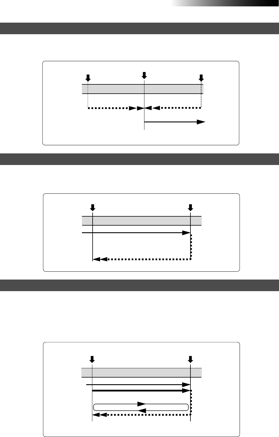
50
MR16 Owner’s Manual (Advanced playback and locate functions)
In the Auto play mode, when locating to the ABS ZERO, REC END, LOCATE A or LOCATE B point,
the recorder automatically starts playback from the point. The following shows the auto play
function after locating to the LOCATE A point (see page 52 for the locate function).
The auto return mode is active when the LOCATE A and LOCATE B points are set.
In the auto return mode, when reaching at the LOCATE B point during playback, the recorder
automatically locates to the LOCATE A point and stops.
As with the auto return mode, the loop mode is active when the LOCATE A and LOCATE B points
are set. In the loop mode, when reaching at the LOCATE B point during playback, the recorder
automatically locates to the LOCATE A point and starts playback. The recorder repeats this
behavior until you stop the recorder.
You may find it very convenience to use the loop function together with the auto punch in/out
function (see the next page).
Auto play mode
Auto return mode
Loop mode
When locating to the LOCATE A point, the recorder
automatically starts playback.
When reaching at the LOCATE B point during
playback, the recorder automatically locates to
the LOCATE A point.
LOCATE A point
Playback
LOCATE B point
LOCATE A point
playback
LOCATE B point
When reaching at the LOCATE B point during playback,
the recorder automatically locates to the LOCATE A
point and stops.
When locating to the LOCATE A point,
the recorder automatically starts
playback immediately.
LOCATE A point
Playback
The point where you
execute the locate function
The point where you
execute the locate function
Locate Locate
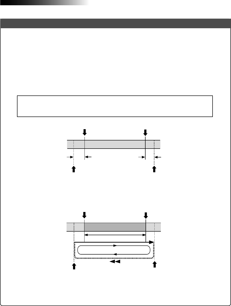
51
MR16 Owner’s Manual (Advanced playback and locate functions)
When the loop mode is active (while the auto punch in/out mode is inactive), the LOCATE
A and LOCATE B points are used as the loop start and end points. When the auto punch in/
out mode is active (while the loop mode is inactive), the LOCATE A and LOCATE B points
are used as the punch-in and punch-out points.
When both the auto punch in/out and loop modes are active, the LOCATE A and LOCATE
B points are used as the punch-in and punch-out points, while the loop function starts at
"the LOCATE A point minus the pre-roll time" and ends at "the LOCATE B point plus the
post-roll time", as shown below. The pre-roll time is initially set to four seconds, while the
post-roll time is set to one second.
Using the loop function in the auto punch in/out mode reduces the number of key presses,
allowing you to concentrate on playing.
LOCATE A point LOCATE B point
4 sec. 1 sec.
LOOP START point LOOP END point
LOCATE A point
(Punch in point) LOCATE B point
(Punch out point)
LOOP START point LOOP END point
You can change the pre-roll and post-roll time within the range between 0.1 and 10.0
seconds (in 0.1 second steps) in the menu mode (see page 142).
<Note>:
If you set the LOCATE A point to the beginning of a song (ABS ZERO) or set the
LOCATE B point to the recording end point (REC END) of a song, the pre-roll or post-roll
time is ignored.
Loop function in auto punch in/out mode
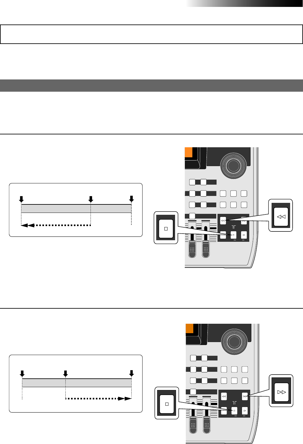
52
MR16 Owner’s Manual (Advanced playback and locate functions)
The following describes the locate functions, which allow you to immediately skip to a specified
point in a song.
Time locate
Regardless of the current recorder position, you can locate to the beginning (ABS ZERO) of the
song or the recording end (REC END) of the song.
• While the recorder is stopped, press the
[REWIND] key while holding down the [STOP] key.
The MR16 immediately locates to the
beginning of the song (ABS ZERO) and stops.
REC END
ABS ZERO
Locate
The current position
REC END
ABS ZERO
Locate
The current position
Locating to the beginning (ABS ZERO) of a song
• While the recorder is stopped, press the [F FWD]
key while holding down the [STOP] key.
The MR16 immediately locates to the
recording end of the song (REC END) and stops.
Locating to the recording end point (REC END) of a song
Locate function
MAX
MIN
MASTER
REC SELECT
RECORD STOP PLAY
REWIND F FWD
UNDO/REDO
STORE
LOCATE REC END
LOCATE ABS ZERO
A-B PLAY
BOUNCE
MASTERING
BRIGHT
15/16 > STEREO WAV FILE
NATURAL
B / OUTA / IN
LOCATE
BOUNCE MODE
CONTRAST
TIMEBASE SELECT
RHYTHM GUIDE DIRECT LOCATE
15/16
DELETE
MENU / ENTER
REWIND
STOP
[STOP] key
[REWIND] key
MAX
MIN
MASTER
REC SELECT
RECORD STOP PLAY
REWIND F FWD
UNDO/REDO
STORE
LOCATE REC END
LOCATE ABS ZERO
A-B PLAY
BOUNCE
MASTERING
BRIGHT
15/16 > STEREO WAV FILE
NATURAL
B / OUTA / IN
LOCATE
BOUNCE MODE
CONTRAST
TIMEBASE SELECT
RHYTHM GUIDE DIRECT LOCATE
15/16
DELETE
MENU / ENTER
F FWD
STOP
[STOP] key
[F FWD] key
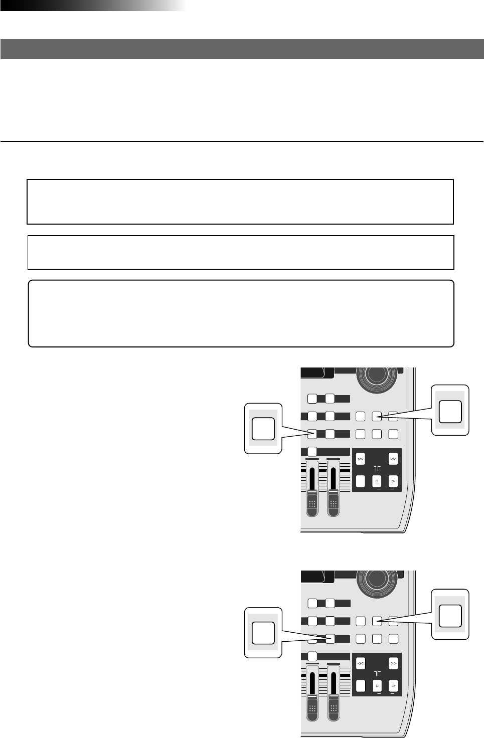
53
MR16 Owner’s Manual (Advanced playback and locate functions)
Locating to the LOCATE A or LOCATE B point
You can set the desired point of a song as the LOCATE A or LOCATE B point.
The LOCATE A and B points can be used not only for locating, but also for auto punch in/out,
play modes and part editing, etc.
Setting the LOCATE A or LOCATE B point
You can set the LOCATE A or LOCATE B point while the recorder is running or stops at the
desired point, regardless of time base setting.
<Note>:
The LOCATE A point must be earlier than the LOCATE B point. If not, you cannot carry
out the auto punch in/out or loop function correctly.
<Tip>: While the time base is set to the bar/beat mode, if you set the "Beat resolution" menu item
in the menu mode to "On", you can store the LOCATE A or B point in beat resolution. In other
words, the clock digit of the Bar/Beat/Clk value is automatically rounded down or up, so that
the clock digit is always "000".
See page 143 for details about how to make the beat resolution active or inactive.
<Note>:
You cannot set the LOCATE A or B point for a protected song. If you are going to do so,
the warning message ("
This song is protected!
") is shown. To set the LOCATE A or B point for a
protected song, release the protection first (see page 117).
• To set the LOCATE B point:
When the recorder is playing back (or
stopped), press the [LOCATE B/OUT] key at
the desired point while holding down the
[STORE] key.
The display briefly shows "Store LOCATE
B", and the point when pressing the
[LOCATE B/OUT] key is stored as the
LOCATE B point.
• To set the LOCATE A point:
When the recorder is playing back (or
stopped), press the [LOCATE A/IN] key at
the desired point while holding down the
[STORE] key.
The display briefly shows "Store LOCATE
A", and the point when pressing the
[LOCATE A/IN] key is stored as the LOCATE
A point.
MAX
MIN
MASTER
REC SELECT
RECORD STOP PLAY
REWIND F FWD
UNDO/REDO
STORE
LOCATE REC END
LOCATE ABS ZERO
A-B PLAY
BOUNCE
MASTERING
BRIGHT
15/16 > STEREO WAV FILE
NATURAL
B / OUTA / IN
LOCATE
BOUNCE MODE
CONTRAST
TIMEBASE SELECT
RHYTHM GUIDE DIRECT LOCATE
15/16
DELETE
MENU / ENTER
STORE
A / IN
MAX
MIN
MASTER
REC SELECT
RECORD STOP PLAY
REWIND F FWD
UNDO/REDO
STORE
LOCATE REC END
LOCATE ABS ZERO
A-B PLAY
BOUNCE
MASTERING
BRIGHT
15/16 > STEREO WAV FILE
NATURAL
B / OUTA / IN
LOCATE
BOUNCE MODE
CONTRAST
TIMEBASE SELECT
RHYTHM GUIDE DIRECT LOCATE
15/16
DELETE
MENU / ENTER
STORE
B/OUT
[STORE] key
[LOCATE A/IN]
key
[STORE] key
[LOCATE B/OUT]
key
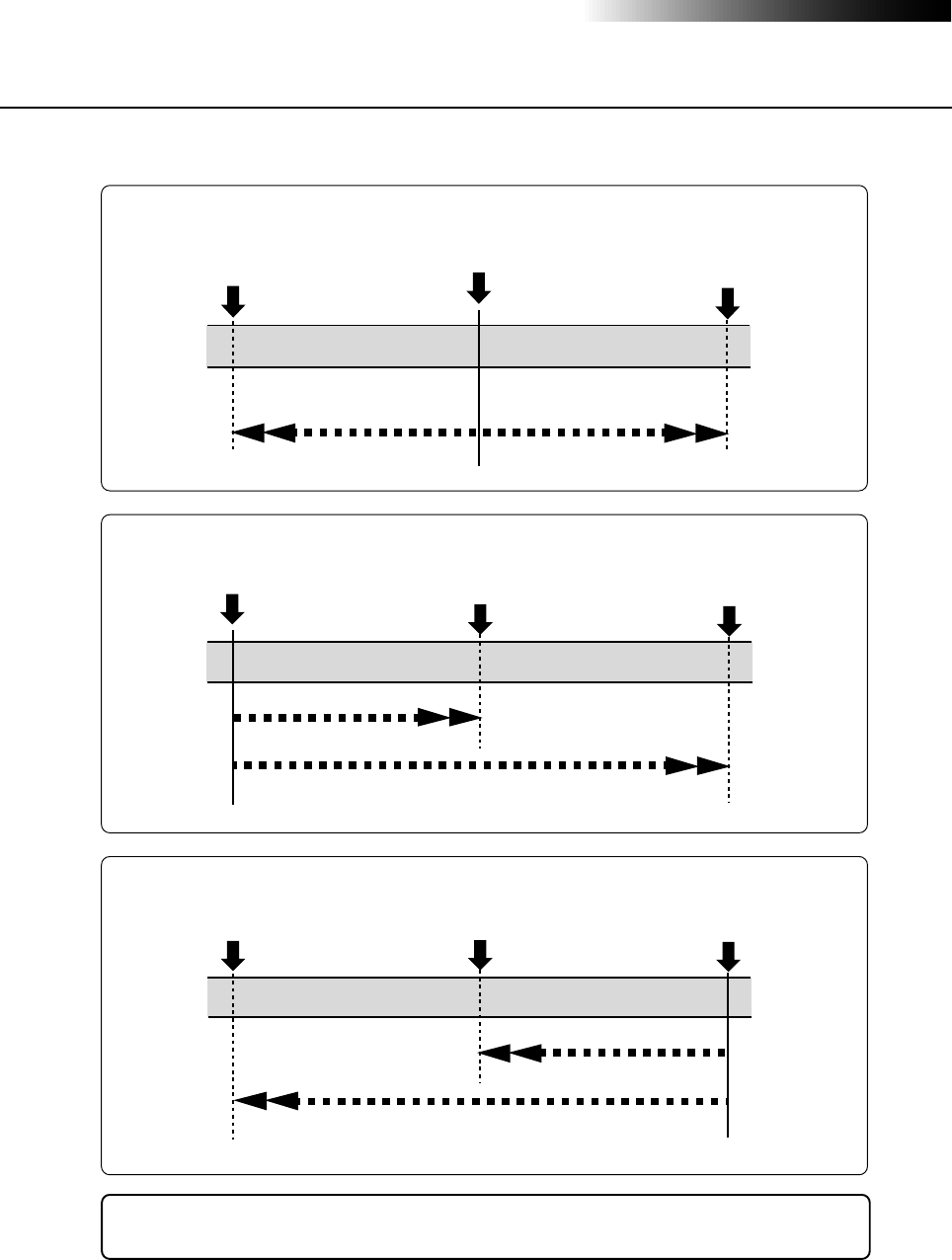
54
MR16 Owner’s Manual (Advanced playback and locate functions)
Locating
While the recorder is stopped, press the [LOCATE A/IN] (or [LOCATE B/OUT]) key.
The recorder instantly locates to the appropriate point.
<Tip>: By selecting the play mode to "Auto play", the recorder automatically starts
playback after locating the LOCATE A or LOCATE B point.
The current position LOCATE B point
LOCATE A point
Locate
Locate
The current position LOCATE B point
LOCATE A point
Locate Locate
The current position
LOCATE B point
LOCATE A point
Locate
Locate
• When the current recorder position is between the LOCATE A and LOCATE B points:
• When the current recorder position is before the LOCATE A and LOCATE B points:
• When the current recorder position is after the LOCATE A and LOCATE B points:
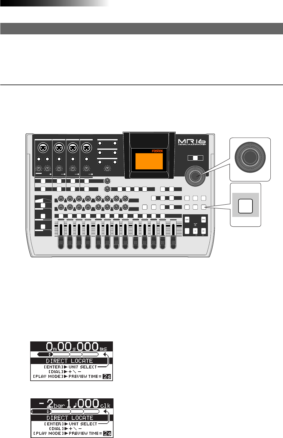
55
MR16 Owner’s Manual (Advanced playback and locate functions)
Direct locate mode
The direct locate mode allows you to locate the desired point specified by measure/beat or time
in a song. To do this, you rotate the [MENU/ENTER] knob instead of using the [REWIND] or [F FWD]
key.
Direct locate mode basics
Use the [DIRECT LOCATE] key to switch on/off of the direct locate mode. Each press of the
[DIRECT LOCATE] key alternates between ON and OFF. When ON, the key indicator lights
up. You can also turn off the direct locate mode by pressing the [STOP] key.
In the direct locate mode, you rotate the [MENU/ENTER] knob for locating the desired point.
PEAK
GUITAR
MIN
DISTORTION
MAX LINE MIC
TRIM
INSERT/GUITAR
UNBAL
BALBALBALBAL
INPUT A INPUT B INPUT C INPUT D
VOLUME
MIN MAX
PEAK
LINE
TRIM
MIC
UNBAL POWER
UNBAL
MIC
TRIM
LINE
PEAK
UNBAL
MIC
TRIM
LINE
PEAK
MAX
MIN
1
R
L
100
SIMULATION SIMULATION
AMP
MIC
010
LR
010
LR
23
RL
100
4 8
010
LR
7
6
RL
100
RL
100
010
LR
5
MAX
MIN
MASTER
REC SELECT
RECORD STOP PLAY
REWIND F FWD
UNDO/REDO
STORE
LOCATE REC END
LOCATE ABS ZERO
A-B PLAY
BOUNCE
MASTERING
BRIGHT
15/16 > STEREO WAV FILE
NATURAL
POWERFUL
B / OUTA / INPLAY MODEAUTO PUNCH
LOCATE
EFFECT
DELAYPLATEHALLROOM BOUNCE MODE
CONTRAST
TIMEBASE SELECT
RHYTHM GUIDE DIRECT LOCATE
EFFECT SEND
PAN
INPUT EQ
TO STEREO BUSS LEVEL
9/10 11/12 13/14 15/16
ABC1 DEF2 GHI3 JKL4 MNO5 YZ9PQR6 +-_0STU7 VWX8 DELETE
MENU / ENTER
MIN MAX
MIN MAX
REVERB / DELAY TIME
LSTEREO OUT R
1AUX OUT 2
1PHONES 2
DYNAMIC BRIT STACK
CONDENSER US METAL
TUBE 60'S COMBO
INPUT A INPUT B INPUT C INPUT D
DIRECT LOCATE
MENU / ENTER
While the recorder is stopped, pressing the [DIRECT LOCATE] key turns on the direct locate
mode and the following "Direct locate" screen appears. Note that the "Direct locate" screen
looks different depending on the time base mode before the unit enters the direct locate
mode (see screen examples below). In this condition, you can use the [MENU/ENTER] rotary
knob to locate the desired position. The time base mode can be changed using the [TIME
BASE SELECT] key after the unit enters the direct locate mode. The following shows the
"Direct locate" screen examples when you enter the direct locate mode while the recorder
is at the beginning of the current song.
Time base mode: ABS
Time Base mode: Bar/Beat
In the screen example on the left, the time base mode is
"ABS" and the locate function by rotating the [MENU/
ENTER] knob is executed with minute accuracy.
For details about how to change the locate accuracy,
see the next page.
In the screen example on the left, the time base mode
is "BAR/BEAT" and the locate function by rotating the
[MENU/ENTER] knob is executed with bar accuracy.
For details about how to change the locate accuracy,
see the next page.
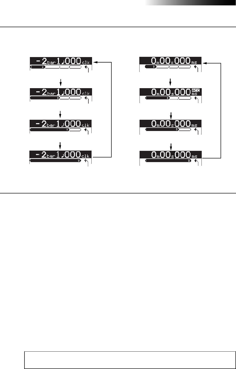
56
MR16 Owner’s Manual (Advanced playback and locate functions)
Setting the locate accuracy
By default, the direct locate function is executed in minute accuracy when the time base is
set to "ABS", while it is executed in measure accuracy when the time base is set to "Bar/
Beat". By pressing the [MENU/ENTER] knob while the direct locate
With bar accuracy
With beat accuracy
With 100 clock accuracy
With 10 clock accuracy
With minute accuracy
With second accuracy
With 100ms accuracy
With 10ms accuracy
Locating the desired bar
During recording process, it often happens that you want to locate the desired bar
accurately. For example, let's assume that a vocalist and an operator are working
together and they want to make punch-in recording from the beginning of the first
bridge. In the typical process, the operator locates the position a few seconds before
the first bridge using the [REWIND] or [F FWD] key, and then starts playback from the
position and punches in at the beginning of the first bridge. In this manner, the vocal-
ist does not know from where playback starts until it starts. Or he (she) may get lost
and miss the punch-in point. If you use the direct locate function, this problem is
solved.
In the following procedure, it is assumed that the time base mode is set to "Bar/Beat".
1) Press the [DIRECT LOCATE] key to enter the direct locate mode.
2) Rotate the [MENU/ENTER] knob to set the locate point to the four bars before the first
bridge.
You need to make a note of the bar number of each part.
3) Tell the vocalist that the playback starts from four bars before the bridge.
If necessary, you can make rehearsal (see page 58 for rehearsal).
4) Press the [STOP] key to exit the direct locate mode and start recording.
Example of using the direct locate function
<Note>:
By setting the locate accuracy to a smaller unit ("bar" or "clock"), you can locate the
point more accurately.

57
MR16 Owner’s Manual (Advanced playback and locate functions)
Locating the desired time
If you know the time at the point you want to locate, the direct locate function allows
you to locate the point accurately by specifying the time.
For example, if you want to locate "12m 34s 540ms" accurately, follow the procedure
below. In the following procedure, it is assumed that the time base mode is set to
"ABS".
1) Press the [DIRECT LOCATE] key to enter the direct locate mode.
2) Rotate the [MENU/ENTER] knob to set the "m" field to "12".
3) Press the [MENU/ENTER] knob to change the locate accuracy unit to "s".
4) Rotate the [MENU/ENTER] knob to set the "s" field to "34".
5) Press the [MENU/ENTER] knob to change the locate accuracy unit to "100ms".
6) Rotate the [MENU/ENTER] knob to set the "100ms" field to "5".
7) Press the [MENU/ENTER] knob to change the locate accuracy unit to "10ms".
8) Rotate the [MENU/ENTER] knob to set the "10ms" field to "40".
9) Press the [STOP] key to exit the direct locate mode.
Adjusting the counter and setting Locate A and Locate B
There is a case that you need to adjust the counter. That is, when you convert the
stereo-mixed audio signals recorded on tracks 15/16 to a stereo WAV file for creating
an audio CD, you need to cut the unnecessary parts at the beginning and end. In such
a case, you need to adjust the counter after editing.
In the following procedure, it is assumed that the time base mode is set to "Bar/Beat".
1) Press the [DIRECT LOCATE] key to enter the direct locate mode.
2) Use the [REWIND] key (or the [F FWD] key) to roughly search the beginning (or end) of the
song.
3) Press the [MENU/ENTER] knob to select the locate accuracy.
4) Rotate the [MENU/ENTER] knob to adjust the counter.
You can check the adjustment by preview playback.
5) After adjusting the counter, press the [LOCATE A/IN] key (or [LOCATE B/OUT] key) while
holding down the [STORE] key to set the Locate A (or Locate B) point.
<Note>:
In the direct locate mode, pressing the [REWIND] key (or the [F FWD] key) allows
audible cueing.
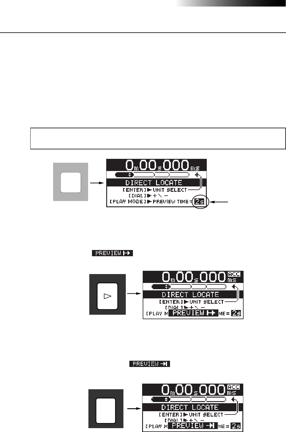
58
MR16 Owner’s Manual (Advanced playback and locate functions)
Previewing the locate point
After executing direct locate function, pressing the [PLAY] key (or [RECORD] key) plays
back two seconds after (or before) the locate point (preview function). The preview time is
set to two seconds by default, however, you can set it to a desired time between one and
four seconds.
Previewing after the locate point
While the direct locate screen is shown, pressing the [PLAY] key executes preview play-
back from the locate point for a few seconds (set by the preview time).
The display shows " " during preview playback. To stop preview play-
back during preview playback, press the [STOP] key.
Previewing before the locate point
While the direct locate screen is shown, pressing the [RECORD] key executes preview
playback from a few seconds (set by the preview time) before the locate point to the
locate point. The display shows " " during preview playback.
To stop preview playback during preview playback, press the [STOP] key.
Setting the preview time
While the direct locate screen is shown, each press of the [PLAY MODE] key switches the
preview time (indicated by an arrow in the screen example below) between "1s", "2s",
"3s" and "4s".
Note that the preview time is reset to "2s" when you turn off the unit.
<Note>:
You can also change the preview time during preview playback. In this case, the new
setting is effective from the next preview playback.
Preview time
PLAY MODE
PLAY
RECORD

59
MR16 Owner’s Manual (Punch in/out)
Punch in/out
Using the punch in/out function of the MR16, you can overwrite the
desired part of the recorded track. "Punch in" means switching from play-
back to recording, while "punch out" means switching from recording to
playback. The MR16 offers three methods for making punch in/out re-
cording.
1) Manual punch in/out using the top panel keys
2) Punch in/out using a footswitch
3) Auto punch in/out at the specified in/out points
The following description assumes that the song you are going to make
punch in/out recording to is loaded and the preparations for recording
is completed.
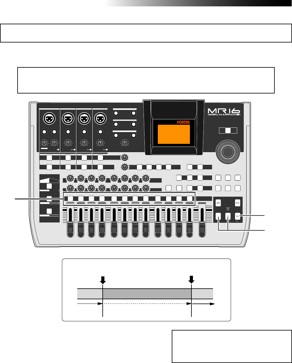
MR16 Owner’s Manual (Punch in/out)
60
1) Press the [REC SELECT] key for the track you
are going to make punch in/out recording.
The track is record-armed.
2) Locate the recorder to the point before the punch-
in point and press the [PLAY] key to start
playback.
It may be a good idea to play the instrument
along with the playback sound, so that you can
get the tempo and feel.
3) When the recorder reaches at the point you want
to punch in, press the [RECORD] key while holding
down the [PLAY] key (see <Important note>).
The armed track is punched in (i.e. starts
recording).
<Note>:
The punch in/out operation by yourself using the keys on the top panel sometimes
prevents you from concentrating on playing. In such a case, ask someone to operate the
MR16, or use either of the other two punch in/out methods described later.
You can make punch in/out manually by using the [RECORD] and [PLAY] keys on the MR16 top
panel.
4) When the recorder reaches at the point you want
to punch out, press only the [PLAY] key.
The recorder status switches from recording
to playback.
5) Press the [STOP] key to stop the recorder.
6) Rewind the recorder and play back the part you
performed the punch in/out recording to check
the result.
If you are not satisfied with the result, use the
undo function to cancel the punch in/out
recording and try again.
PEAK
GUITAR
MIN
DISTORTION
MAX LINE MIC
TRIM
INSERT/GUITAR
UNBAL
BALBALBALBAL
INPUT A INPUT B INPUT C INPUT D
VOLUME
MIN MAX
PEAK
LINE
TRIM
MIC
UNBAL POWER
UNBAL
MIC
TRIM
LINE
PEAK
UNBAL
MIC
TRIM
LINE
PEAK
MAX
MIN
1
R
L
100
SIMULATION SIMULATION
AMP
MIC
010
LR
010
LR
23
RL
100
4 8
010
LR
7
6
RL
100
RL
100
010
LR
5
MAX
MIN
MASTER
REC SELECT
RECORD STOP PLAY
REWIND F FWD
UNDO/REDO
STORE
LOCATE REC END
LOCATE ABS ZERO
A-B PLAY
BOUNCE
MASTERING
BRIGHT
15/16 > STEREO WAV FILE
NATURAL
POWERFUL
B / OUTA / INPLAY MODEAUTO PUNCH
LOCATE
EFFECT
DELAYPLATEHALLROOM BOUNCE MODE
CONTRAST
TIMEBASE SELECT
RHYTHM GUIDE DIRECT LOCATE
EFFECT SEND
PAN
INPUT EQ
TO STEREO BUSS LEVEL
9/10 11/12 13/14 15/16
ABC1 DEF2 GHI3 JKL4 MNO5 YZ9PQR6 +-_0STU7 VWX8 DELETE
MENU / ENTER
MIN MAX
MIN MAX
REVERB / DELAY TIME
LSTEREO OUT R
1AUX OUT 2
1PHONES 2
DYNAMIC BRIT STACK
CONDENSER US METAL
TUBE 60'S COMBO
INPUT A INPUT B INPUT C INPUT D
1
3
2,4
<Important note>
You cannot punch in by only pressing the
[
RECORD
] key. You need to hold down the
[
PLAY
] key when pressing the [
RECORD
] key.
Press the [RECORD] key
while holding down the [PLAY] key.
(Punch in)
Press only the [PLAY] key.
(Punch out)
Playback Recording Playback
Punch in/out using the keys on the top panel
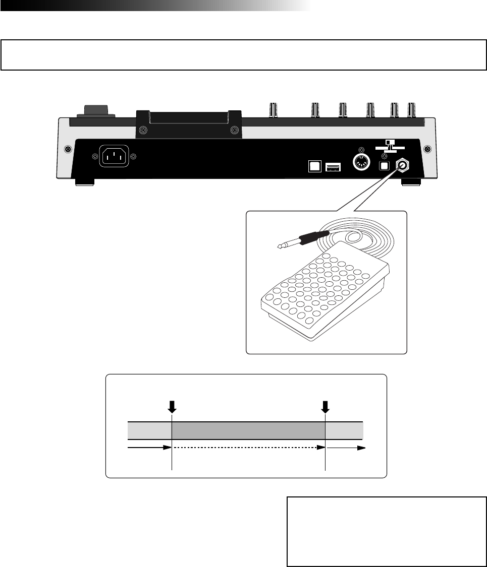
61
MR16 Owner’s Manual (Punch in/out)
USB USB HOST MIDI OUT DIGITAL OUT FOOT SW
INPUT A SEL
GTR CLEAN MIC/LINE
GTR DIST
1) Connect the footswitch to the [FOOT SW] jack
on the MR16 rear panel.
2) Press the [REC SELECT] key for the track you
are going to make punch in/out recording.
The track is record-armed.
3) Locate the recorder to the point before the punch-
in point, and press the [PLAY] key to start play
back.
It may be a good idea to play the instrument
along with the playback sound, so that you can
get the tempo and feel.
4) When the recorder reaches at the point you want
to punch in, press the footswitch.
The armed track is punched in (i.e. starts
recording).
5) When the recorder reaches at the point you want
to punch out, press the footswitch again.
The recorder status switches from recording
to playback.
You can make hands-free punch in/out recording using an unlatched-type footswitch.
<Note>:
You cannot perform another punch
in/out recording successively.
To perform punch in/out recording in an-
other part, stop the recorder and perform
the steps above again.
[FOOT SW] jack
Unlatched-type footswitch
6) Press the [STOP] key to stop the recorder.
7) Rewind the recorder and play back the part you
performed the punch in/out recording to check
the result.
If you are not satisfied with the result, use the
undo function to cancel the punch in/out
recording and try again.
Press the footswitch.
(Punch in)
Playback Recording Playback
Press the footswitch.
(Punch out)
Punch in/out using the footswitch
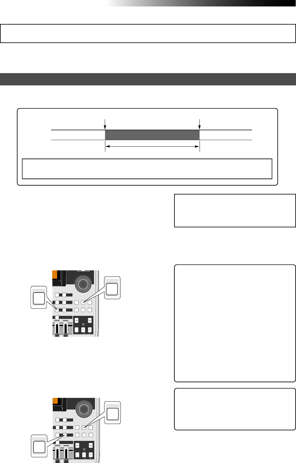
MR16 Owner’s Manual (Punch in/out)
62
By setting the punch-in and punch-out points in advance, the recorder automatically makes
punch in/out recording for you. You can rehearse punch in/out recording as many times you
like.
Setting the punch-in and punch-out points
3) When the recorder reaches at the point where
you want to make punching out, press the
[LOCATE B/OUT] key while holding down the
[STORE] key.
The display briefly shows "Store LOCATE B" and
the time data when you press the
[LOCATE B/OUT] key is set as the punch-out
point.
4) Stop the recorder after setting the punch-in and
punch-out points, and rewind the recorder to the
beginning of the song (or to a point before the
point where you want to make punching in).
<Hint>: The punch-in and punch-out
points you set also can be used for the
locate function, playback by the play
mode and part editing (see pages 47 and
127).
<Note>:
If you are not satisfied with the
punch-in or punch-out point you set, sim-
ply redo the operation above. The new time
data overwrites the previous one.
1) Start playback from the beginning of the song
(or from a point before the point where you want
to make punching in) by pressing the [PLAY] key.
2) When the recorder reaches at the point where
you want to make punching in, press the
[LOCATE A/IN] key while holding down the
[STORE] key.
The display briefly shows "Store LOCATE A" and
the time data when you press the
[LOCATE A/IN] key is set as the punch-in point.
<Note>:
You cannot make punch-in/out recording on a song which is protected. Release the
song protection before making punch-in/out recording.
Punch-in point Punch-out point
Part replaced with a new recording
<Hint>: To rewind the recorder to the be-
ginning of the song after setting the
punch-out point, press the [REWIND] key
while holding down the [STOP] key.
To locate before the punch-in point, carry
out the following.
(1) While the recorder is stopped, press
the [LOCATE A/IN] key.
The recorder immediately locates to
the punch-in point and stops.
(2) Press the [REWIND] key to move back
the recorder and press the [STOP] key
at the desired point.
You can set the punch-in and punch-out points on-the-fly while playing back the recorder (as
well as you can set them while the recorder is stopped at the desired position).
Auto punch in/out
MAX
MIN
MASTER
REC SELECT
RECORD STOP PLAY
REWIND F FWD
UNDO/REDO
STORE
LOCATE REC END
LOCATE ABS ZERO
A-B PLAY
BOUNCE
MASTERING
BRIGHTNATURAL
B / OUTA / IN
LOCATE
BOUNCE MODE
CONTRAST DIRECT LOCATE
15/16
DELETE
MENU / ENTER
15/16 > STEREO WAV FILE
TIMEBASE SELECT
RHYTHM GUIDE
STORE
A / IN
MAX
MIN
MASTER
REC SELECT
RECORD STOP PLAY
REWIND F FWD
UNDO/REDO
STORE
LOCATE REC END
LOCATE ABS ZERO
A-B PLAY
BOUNCE
MASTERING
BRIGHTNATURAL
B / OUTA / IN
LOCATE
BOUNCE MODE
CONTRAST DIRECT LOCATE
15/16
DELETE
MENU / ENTER
15/16 > STEREO WAV FILE
TIMEBASE SELECT
RHYTHM GUIDE
STORE
B / OUT
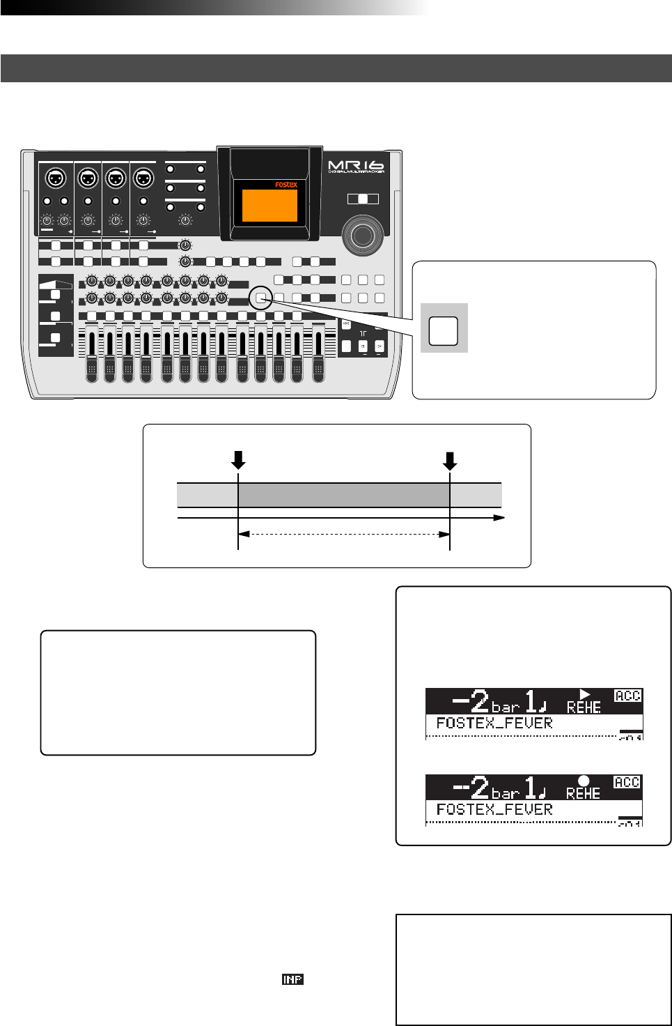
63
MR16 Owner’s Manual (Punch in/out)
After setting the punch-in and punch-out points appropriately, you can rehearse the auto punch
in/out for checking the punch-in and -out points or practicing punch-in and -out timing.
<Tip>: You can immediately locate to the
punch-in point by pressing the
[LOCATE A/IN] key. Therefore, by pressing
the [LOCATE A/IN] key, followed by the [RE-
WIND] key then the [STOP] key, you can
easily locate to the point before the punch-
in point.
1) Locate the recorder to the point before the punch-
in point (or the beginning of the song).
4) Press the [PLAY] key.
In the rehearsal mode, the recorder
automatically switches the monitor of the
armed track from "repro" to "input" at the
punch-in point, but actual recording is not
made (the [RECORD] key flashes while " "
is shown on the display.
By repeating the operation above, you can
practice auto in/out operation as many times
as you like.
2) Press the [REC SELECT] key of the track you are
going to make punch in/out operation to arm the
track.
3) Press the [AUTO PUNCH] key to make the auto
punch mode active.
The [AUTO PUNCH] key is lit.
<Note>:
By using the loop function when
rehearsing the auto punch in/out operation,
you can concentrate on playing without the
need of troublesome operation of the MR16.
See page 49 for details about the loop func-
tion.
5) After the punch-out point is passed, locate the
recorder back to the beginning position.
PEAK
GUITAR
MIN
DISTORTION
MAX LINE MIC
TRIM
INSERT/GUITAR
UNBAL
BALBALBALBAL
INPUT A INPUT B INPUT C INPUT D
VOLUME
MIN MAX
PEAK
LINE
TRIM
MIC
UNBAL POWER
UNBAL
MIC
TRIM
LINE
PEAK
UNBAL
MIC
TRIM
LINE
PEAK
MAX
MIN
1
R
L
100
SIMULATION SIMULATION
AMP
MIC
010
LR
010
LR
23
RL
100
4 8
010
LR
7
6
RL
100
RL
100
010
LR
5
MAX
MIN
MASTER
REC SELECT
RECORD STOP PLAY
REWIND F FWD
UNDO/REDO
STORE
LOCATE REC END
LOCATE ABS ZERO
A-B PLAY
BOUNCE
MASTERING
BRIGHT
15/16 > STEREO WAV FILE
NATURAL
POWERFUL
B / OUTA / INPLAY MODEAUTO PUNCH
LOCATE
EFFECT
DELAYPLATEHALLROOM BOUNCE MODE
CONTRAST
TIMEBASE SELECT
RHYTHM GUIDE DIRECT LOCATE
EFFECT SEND
PAN
INPUT EQ
TO STEREO BUSS LEVEL
9/10 11/12 13/14 15/16
ABC1 DEF2 GHI3 JKL4 MNO5 YZ9PQR6 +-_0STU7 VWX8 DELETE
MENU / ENTER
MIN MAX
MIN MAX
REVERB / DELAY TIME
LSTEREO OUT R
1AUX OUT 2
1PHONES 2
DYNAMIC BRIT STACK
CONDENSER US METAL
TUBE 60'S COMBO
INPUT A INPUT B INPUT C INPUT D
AUTO PUNCH
<How to make auto punch in/out mode active>
Rehearsal for auto punch in/out
Pressing the [AUTO PUNCH] key
switches the auto punch in/out
mode on or off.
Each press of the [AUTO PUNCH]
key turns on or off the indicator.
Punch-in point Punch-out point
Playback
Input monitor
Playback
<Hint>:
During rehearsal, "REHE" is lit in the
time display section on the screen, so that
you can know that the recorder is now in
the rehearsal mode.
Now playing back in the rehearsal mode.
Now rehearsing recording.
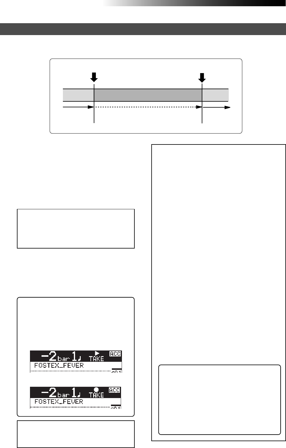
MR16 Owner’s Manual (Punch in/out)
64
After rehearsing the auto punch-in/out operation, it's time for executing actual auto punch in/
out operation.
1) Locate the recorder to the point before the punch-
in point.
2) Confirm that the auto punch mode is active.
If it is not active, press the [AUTO PUNCH] key
to make it active.
3) Press the [RECORD] key while holding down the
[PLAY] key.
<Note>:
You can cancel the auto punch in/
out recording you made by pressing the
[
UNDO/REDO
] key.
<Note>:
In addition to the punch in/out func-
tion, the MR16 allows you to edit the recorded
material using the following editing functions.
• Deleting the whole data on the desired
track (using the "Erase Track" menu item).
See page 120.
• Copying all data on a track and pasting it
to another track (using the "Copy Paste
Track" menu item). See page 121.
• Moving the desired track data to the other
track(s) (using the "Move Track" menu
item). See page 123.
• Exchanging all track data between tracks
(using the "Change Track" menu item). See
page 125.
• Deleting the desired part (using the "Erase
Part" menu item). See page 128.
• Pasting the desired part(s) to the other
track(s) (using the "Copy Paste Part" menu
item or the "Copy Part" and "Paste Part"
menu items). See pages 129 and 131.
• Moving the desired part(s) to the other
track(s) (using the "Move Part" menu item).
See page 134.
• Exchanging parts between tracks (using the
"Change Part" menu item). See page 136.
<About "part">: A "part" is defined as au-
dio data between the "LOCATE A" and "LO-
CATE B" points. Therefore, you have to set
the "LOCATE A" and "LOCATE B" points
when editing a "part".
The punch-in and punch-out points set
for the auto punch in/out function also
can be used as the "LOCATE A" and "LO-
CATE B" points.
Actual auto punch in/out
Punch out point
Playback Recording Playback
Punch in point
Unlike the rehearsal, the recorder automati-
cally starts recording when it reaches the
punch-in point, then automatically stops re-
cording and exits the auto punch mode at the
punch-out point.
<Note>:
In the rehearsal mode, you press
only the
[PLAY]
key. In the actual auto
punch-in operation, make sure to press the
[RECORD]
key while holding down the
[PLAY]
key.
<Hint>:
During actual auto punch in/out
mode, "TAKE" is lit in the time display sec-
tion on the screen, so that you can know
that the recorder is now in the actual auto
punch in/out mode.
Now playing back in the actual
auto punch in/out mode.
Now actual auto punch in/out recording.

65
MR16 Owner’s Manual (Using effects)
Using effects
The MR16 provides the input equalizer and the insert effects for record-
ing (microphone and amplifier simulation effects), the delay/reverb ef-
fects for track bounce or mixdown (for tracks 1 through 8 only), and the
mastering effects for L/R mix. You can also use an external effect device
connected to the [INSERT] connector.
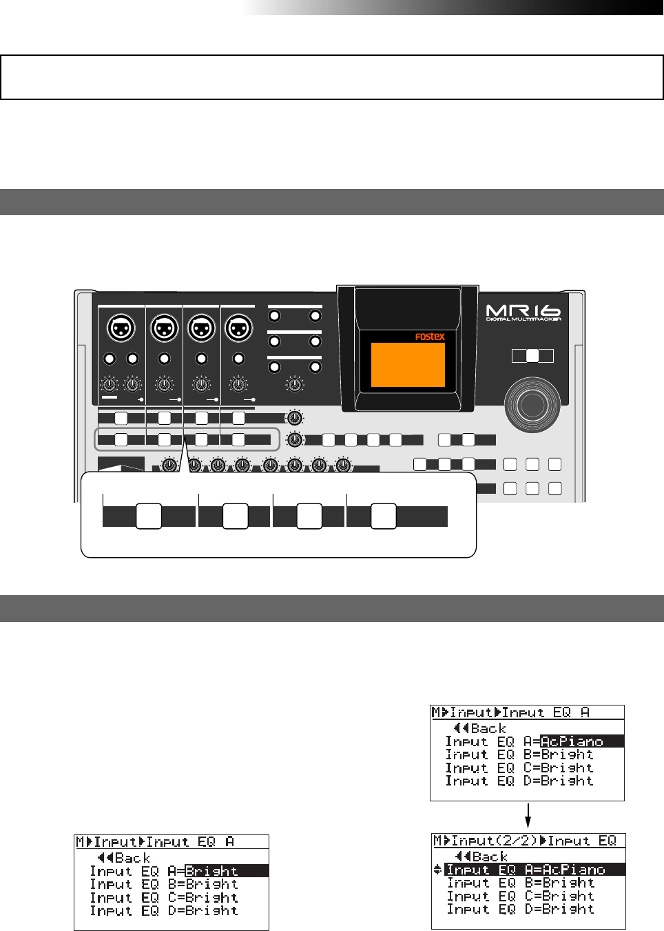
66
MR16 Owner’s Manual (Using effects)
The MR16 provides the input EQ (equalizer) for each of input channels (A through D).
You can apply the input EQ to each recording source to tailor the sound as you wish. You can
select a desired setting from among 33 presets in the EQ library.
Using the input EQ for recording
To turn on the input EQ for a desired input channel, press the appropriate [INPUT EQ] key.
Each press of the [INPUT EQ] key alternates On and Off of the input EQ. When On, the key is lit.
When Off, it is unlit.
Turning of the input EQ
PEAK
GUITAR
MIN
DISTORTION
MAX LINE MIC
TRIM
INSERT/GUITAR
UNBAL
BALBALBALBAL
INPUT A INPUT B INPUT C INPUT D
VOLUME
MIN MAX
PEAK
LINE
TRIM
MIC
UNBAL
POWER
UNBAL
MIC
TRIM
LINE
PEAK
UNBAL
MIC
TRIM
LINE
PEAK
R
L
100
SIMULATION SIMULATION
AMP
MIC
010
LR
010
LR RL
100 010
LR
RL
100
RL
100
010
LR
UNDO/REDO
STORE
BOUNCE
MASTERING
BRIGHT
15/16 > STEREO WAV FILE
NATURAL
POWERFUL
B / OUTA / INPLAY MODEAUTO PUNCH
LOCATE
EFFECT
DELAYPLATEHALLROOM BOUNCE MODE
CONTRAST
TIMEBASE SELECT
RHYTHM GUIDE DIRECT LOCATE
EFFECT SEND
PAN
INPUT EQ
TO STEREO BUSS LEVEL
MENU / ENTER
MIN MAX
MIN MAX
REVERB / DELAY TIME
LSTEREO OUT R
1AUX OUT 2
1PHONES 2
DYNAMIC BRIT STACK
INPUT A INPUT B INPUT C INPUT D
INPUT EQ
[INPUT EQ] key
You can select a desired EQ preset in the EQ library by the procedure below. The selected input
EQ preset setting is enabled by turning on the [INPUT EQ] key. You can select a desired input EQ
preset to each input individually (see the table on the next page for details of EQ library).
Selecting a desired EQ preset entry
1) While the recorder is stopped, press and hold
the appropriate [INPUT EQ] key for the desired
input channel until the "Input" menu screen of
the MENU mode is shown on the display.
The following shows the screen example which
appears by pressing the [INPUT EQ] key for
Input A.
You can now select a desired EQ preset.
2) Rotate the [MENU/ENTER] knob to select the
desired EQ preset and press the [MENU/ENTER]
knob.
The selected EQ preset is applied.
The following screen examples show when you
select "AcPiano" to Input A.
Execute the similar operations as above for
setting EQ for other Inputs.
3) Press the [STOP] key to exit the setting screen.
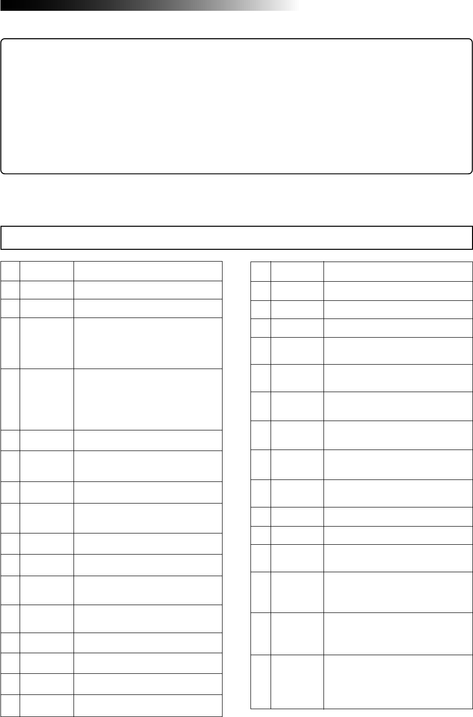
67
MR16 Owner’s Manual (Using effects)
<Hint>: You can also make input EQ setting by the following procedure.
(1) While the recorder is stopped, press the [MENU/ENTER] knob to enter the MENU mode.
(2) Rotate the [MENU/ENTER] knob to select "Input" on the second page and press the [MENU/ENTER]
knob.
(3) Use the [MENU/ENTER] knob to select the EQ setting item for the desired input channel and press the
[MENU/ENTER] knob.
(4) Use the [MENU/ENTER] knob to select the desired input EQ preset and press the [MENU/ENTER] knob.
(5) Press the [STOP] key to exit the MENU mode.
L01
L02
L03
L04
L05
L06
L07
L08
L09
L10
L11
L12
L13
L14
L15
L16
L17
Bright
Loudness
Warm
TightDrs
LoudDrums
HeavyKick
TightKick
NormSnare
FatSnare
WarmBass
TightBass
AcGuitar
DistGtr
AcPiano
WarmVocal
BrightVoc
B.G.Vocal
Enhances the brightness of a sound.
Enhances the loudness to a sound.
Adds a warm feel to a sound.
Used for the top microphone for a drum
kit. Also used for drum kit channels for
stereo mixing. You can get a tight sound
by cutting the mid frequency range.
Used for the top microphone for a drum
kit. Also used for drum kit channels for
stereo mixing. You can get a natural
drum sound by enhancing the low and
high frequency ranges moderately.
Adds thickness.
Adds fatness to the low frequency range
and emphasizes attack.
Enhances a snappy feel to a snare.
Enhances fatness to a snare, as well as
sharpness of high frequency range.
Add warmness to a bass sound.
Tightens a bass sound.
Enhances presence to an acoustic gui-
tar sound.
Adds fatness and presence to a distorted
guitar sound.
Good for an acoustic piano in ensemble.
Adds a warm feel to a vocal.
Adds brightness to a vocal.
Good for backing vocals.
L19
L20
L21
L22
L23
L24
L25
L26
L27
L28
L29
L30
L31
L32
L33
Radio1
Radio2
Radio3
HPF-50
HPF-100
HPF-160
HPF-250
LPF-12K
LPF-6.3K
HumRmv50
HumRmv60
NoiseRmv1
NoiseRmv2
NoiseRmv3
PhaseInv
Radio sound 1
Radio sound 2
Radio sound 3
Applies a 50 Hz high-pass filter to cut
the unnecessary low frequency range.
Applies a 100 Hz high-pass filter to cut
the unnecessary low frequency range.
Applies a 160 Hz high-pass filter to cut
the unnecessary low frequency range.
Applies a 250 Hz high-pass filter. Effec-
tive for cutting the wind noise.
Applies a 12 kHz low-pass filter to cut
the unnecessary high frequency range.
Applies a 6.3 kHz low-pass filter to cut
the unnecessary high frequency range.
Removes 50 Hz hum noise.
Removes 60 Hz hum noise.
Removes white noise. Effective for a
brighter sound.
Removes white noise. This is stronger
than L30.
Effective for a too bright sound.
Removes white noise. This is stronger
than L31.
Effective for a too bright sound.
Inverts phase. Note that when more than
one microphone is used for an instru-
ment, inverting phase may boost the low
frequency range.
EQ library
L18 Narration Good for narration.
<Note>:
The contents of EQ library may change with the software upgrade in the future.
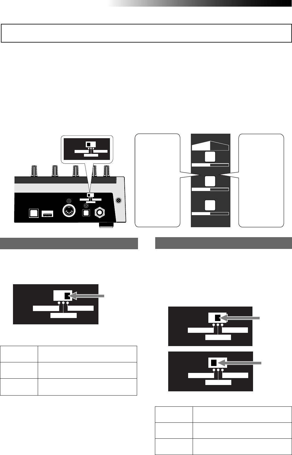
68
MR16 Owner’s Manual (Using effects)
• Details of each mic simulation effect
DYNAMIC
CONDENSER
TUBE
Simulates the sound of a popular dy-
namic microphone.
Simulates the sound of a popular con-
denser microphone for professional use.
Simulates the sound of a popular tube
microphone for professional use.
• Amp simulation effects details
BRIT STACK
US METAL
60’s COMBO
Simulates a popular British 800-series
tube guitar amp head.
Simulates a popular US high gain metal
guitar amplifier.
Simulates a popular tube combo guitar
amplifier.
Using the insert effects for recording
The insert effects can be applied only to the Input A channel.
The insert effects include the mic simulation and amplifier simulation effects, which simulate
popular microphones and guitar amplifiers. Depending on the setting of the [INPUT A SEL] switch
on the rear panel, the appropriate simulation effect (mic simulation or amplifier simulation) is
applied.
If you use the microphone simulation effect when you record an acoustic guitar through your
microphone, you can make recording as if you are using a famous microphone. If you use the
guitar amplifier simulation effect when you record an electric guitar directly connected to the
MR16, you can make recording as if you are using a famous guitar amplifier.
Note that you cannot get exactly the same sound as the original microphone/guitar amplifier by
using simulation effects.
You can use mic simulation effects when the
[INPUT A SEL] switch on the rear panel is set
to "MIC/LINE".
“MIC/LINE”
Mic simulation effects Amp simulation effects
“GTR DIST”
“GTR CLEAN”
You can use mic simulation effects when the
[INPUT A SEL] switch on the rear panel is set
to "GTR DIST" or "GTR CLEAN". Only when the
switch is set to "GTR DIST", you can also use
the distortion (adjusted by the [DISTORTION]
control), as well as the insert effects.
USB USB HOST MIDI OUT DIGITAL OUT FOOT SW
INPUT A SEL
GTR CLEAN MIC/LINE
GTR DIST
INPUT A SEL
GTR CLEAN MIC/LINE
GTR DIST
SIMULATION SIMULATION
AMP
MIC
DYNAMIC BRIT STACK
CONDENSER US METAL
TUBE 60'S COMBO
When the mic
simulation effect
is enabled, you
can select the
type from DY-
NAMICS, CON-
DENSER and
TUBE. The key
for the selected
type is lit.
When the ampli-
fier simulation ef-
fect is enabled,
you can select
the type from
BRIT STACK,
US METAL and
60'S COMBO.
The key for the
selected type is
lit.
INPUT A SEL
GTR CLEAN MIC/LINE
GTR DIST
INPUT A SEL
GTR CLEAN MIC/LINE
GTR DIST
INPUT A SEL
GTR CLEAN MIC/LINE
GTR DIST
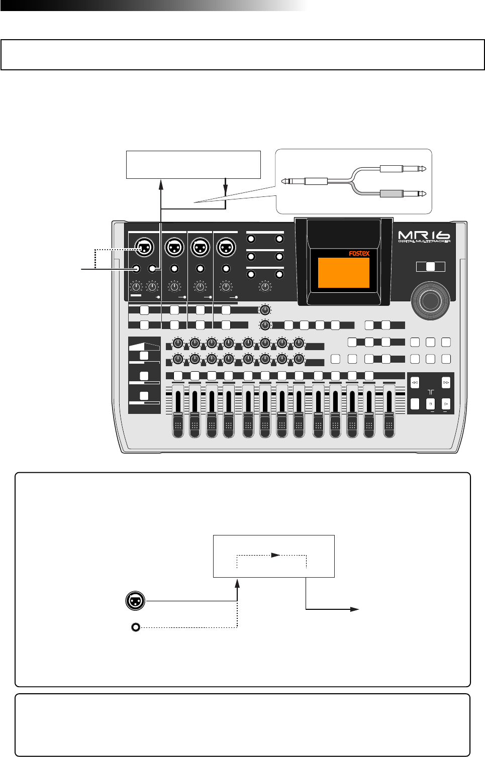
69
MR16 Owner’s Manual (Using effects)
During recording, you can apply external effects to a sound source connected to an input con-
nector in the [INPUT A] channel.
The [INPUT A] channel has the [INSERT] connector (phone jack). You can connects an external
effect unit (typically, a compressor/limiter) to this connector using a Y-cable, as shown below.
PEAK
GUITAR
MIN
DISTORTION
MAX LINE MIC
TRIM
INSERT/GUITAR
UNBAL
BALBALBALBAL
INPUT A INPUT B INPUT C INPUT D
VOLUME
MIN MAX
PEAK
LINE
TRIM
MIC
UNBAL
POWER
UNBAL
MIC
TRIM
LINE
PEAK
UNBAL
MIC
TRIM
LINE
PEAK
MAX
MIN
1
R
L
100
SIMULATION SIMULATION
AMP
MIC
010
LR
010
LR
23
RL
100
4 8
010
LR
7
6
RL
100
RL
100
010
LR
5
MAX
MIN
MASTER
REC SELECT
RECORD STOP PLAY
REWIND F FWD
UNDO/REDO
STORE
LOCATE REC END
LOCATE ABS ZERO
A-B PLAY
BOUNCE
MASTERING
BRIGHT
15/16 > STEREO WAV FILE
NATURAL
POWERFUL
B / OUTA / INPLAY MODEAUTO PUNCH
LOCATE
EFFECT
DELAYPLATEHALLROOM BOUNCE MODE
CONTRAST
TIMEBASE SELECT
RHYTHM GUIDE DIRECT LOCATE
EFFECT SEND
PAN
INPUT EQ
TO STEREO BUSS LEVEL
9/10 11/12 13/14 15/16
ABC1 DEF2 GHI3 JKL4 MNO5 YZ9PQR6 +-_0STU7 VWX8 DELETE
MENU / ENTER
MIN MAX
MIN MAX
REVERB / DELAY TIME
LSTEREO OUT R
1AUX OUT 2
1PHONES 2
DYNAMIC BRIT STACK
CONDENSER US METAL
TUBE 60'S COMBO
INPUT A INPUT B INPUT C INPUT D
EFFECTOR (COMP/LIMITER) etc.
Input Output
Sound source
INPUT A
EFFECTOR
Input Output
The source (dry) signal fed to the [INPUT A] channel is sent to the external effect unit
connected to the [INSERT] connector and the wet (effect) signal returns to the [INPUT A]
channel. Thus, you can apply effects to the "INPUT A" signal by connecting an external
effect unit.
See the manual of your effect unit for details about how to use it.
A Y-cable is not supplied with the MR16, therefore, purchase an appropriate Y-cable
available in the market.
Sound source Dry (original) sound Wet (effect) sound
Using external effects for recording
<Hint>: The unit provides two pairs of the [AUX OUT] connectors. During mixdown, you
can apply an effect to the desired tracks by connecting an external effect unit to the
[AUX OUT] connectors. For details about how to use the [AUX OUT] connectors, see "Ap-
plication examples" on page 149.
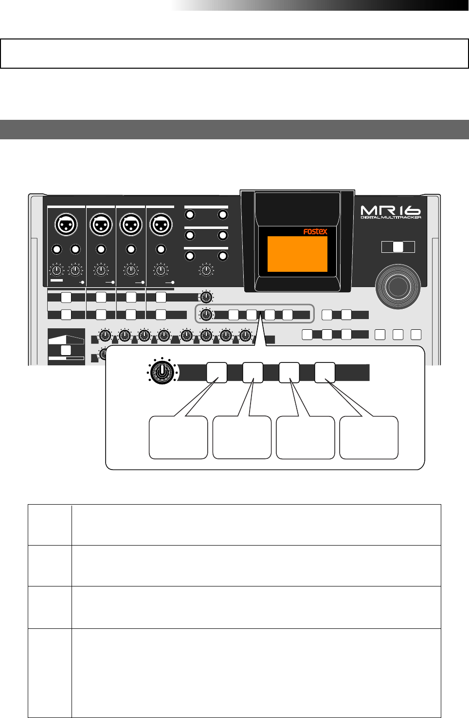
70
MR16 Owner’s Manual (Using effects)
Selecting an effect type
The MR16 has the original built-in reverb/delay processor featuring the newly-developed algo-
rithm. You can apply the reverb or delay to playback signals of tracks 1 through 8 during
mixdown and track bouncing.
Details of each effect type
ROOM
HALL
PLATE
DELAY
Simulates reverberation in a medium-sized room. When you select "ROOM", you can adjust the
reverb time using the [REVERB/DELAY TIME] control.
Simulates reverberation in a hall with moderate early reflection.
When you select "HALL", you can adjust the reverb time using the [REVERB/DELAY TIME]
control.
Simulates a plate reverb with a wide frequency range.
When you select "PLATE", you can adjust the reverb time using the [REVERB/DELAY TIME]
control.
Adds delay effects. You can select the desired delay types using the "Delay Type" item of the
System menu in the menu mode (you can easily access to the "Delay Type" setting screen by a
long press of the [DELAY] key).
Three delay types are available: Mono, L-R and Diff. See below for details.
When you select "ROOM", you can adjust the delay time using the [REVERB/DELAY TIME]
control.
You can select an effect type from among three reverb options (ROOM, HALL and PLATE) and a
delay (DELAY) by using the keys in the [EFFECT] section shown below (the currently selected key
is lit).
Using the internal reverb or delay
PEAK
GUITAR
MIN
DISTORTION
MAX LINE MIC
TRIM
INSERT/GUITAR
UNBAL
BALBALBALBAL
INPUT A INPUT B INPUT C INPUT D
VOLUME
MIN MAX
PEAK
LINE
TRIM
MIC
UNBAL
POWER
UNBAL
MIC
TRIM
LINE
PEAK
UNBAL
MIC
TRIM
LINE
PEAK
R
L
100
SIMULATION SIMULATION
AMP
MIC
010
LR
010
LR RL
100 010
LR
RL
100
RL
100
010
LR
UNDO/REDO
STORE
BOUNCE
MASTERING
BRIGHT
15/16 > STEREO WAV FILE
NATURAL
POWERFUL
B / OUTA / INPLAY MODEAUTO PUNCH
LOCATE
EFFECT
DELAYPLATEHALLROOM BOUNCE MODE
CONTRAST
TIMEBASE SELECT
RHYTHM GUIDE DIRECT LOCATE
EFFECT SEND
PAN
INPUT EQ
TO STEREO BUSS LEVEL
MENU / ENTER
MIN MAX
MIN MAX
REVERB / DELAY TIME
LSTEREO OUT R
1AUX OUT 2
1PHONES 2
DYNAMIC BRIT STACK
INPUT A INPUT B INPUT C INPUT D
EFFECT
DELAYPLATEHALLROOM
MIN MAX
REVERB / DELAY TIME
Select this when
you want to use
a room reverb.
Select this when
you want to use
a hall reverb.
Select this when
you want to use
a plate reverb.
Select this when
you want to use
a delay effect.
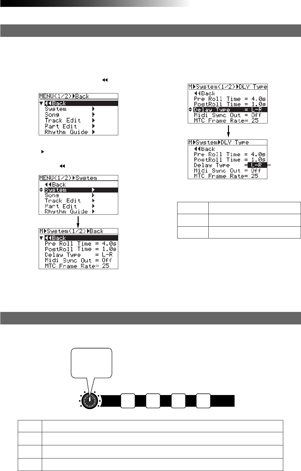
71
MR16 Owner’s Manual (Using effects)
2) Rotate the [MENU/ENTER] knob to select
"System ", and press the [MENU/ENTER] knob.
The display now shows the system menu
screen, where " Back" is highlighted.
1) While the recorder is stopped, press the
[MENU/ENTER] knob to enter the menu mode.
The display now shows the first page of the
menu selection screen, where " Back" is
highlighted initially.
When you use the delay effect, you can select a delay type.
3) Rotate the [MENU/ENTER] knob to select
"Delay Type" and press the [MENU/ENTER] knob.
Selecting a delay type
Flashing
The current delay type starts flashing and you
can now select from among three options
shown below ("L-R" is initially selected).
4) Rotate the [MENU/ENTER] knob to select the
desired delay type and press the [MENU/ENTER]
knob.
The selected delay type is set, while the
display returns to the previous screen.
5) Press the [STOP] key to quit the menu mode.
You can choose from among the following three
delay types.
L - R
Mono
Diff
L-R delay (default)
Mono delay
Diffusion delay
HALL
ROOM
PLATE
DELAY
Adjusts the reverb time within the range between 1.0 s and 6.0 s (center position: 3.0 s)
Adjusts the reverb time within the range between 0.1 s and 2.0 s (center position: 1.0 s)
Adjusts the reverb time within the range between 0.5 s and 4.0 s (center position: 2.0 s)
Adjusts the delay time within the range between 100 ms to 1000 ms (center position: 300 ms)
You can adjust the reverb time or delay time using the [REVERB/DELAY TIME] control, depending
on the selected effect type.
Adjusting the delay/reverb time
EFFECT
DELAYPLATEHALLROOM
MIN MAX
REVERB / DELAY TIME
Adjusts
reverb or
delay time.
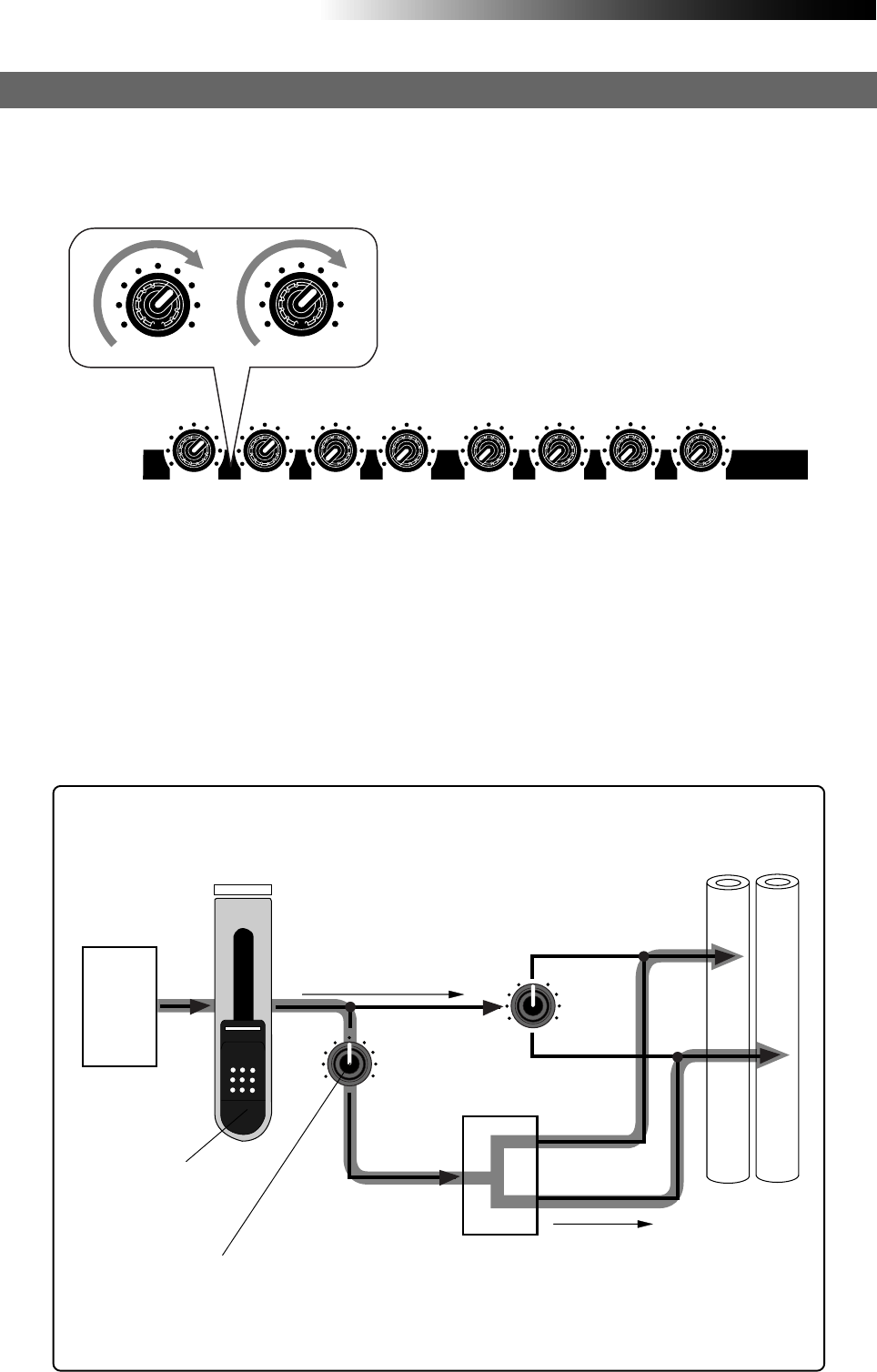
72
MR16 Owner’s Manual (Using effects)
Track 1
1
010
Delay
or
Reverb
LR
EFFECT SEND
PAN
STEREO BUSS
LR
As shown in the signal flowchart below, a track (playback) signal after the track fader
is fed to the [EFFECT SEND] control and adjusted, then fed to the effect processor
input.
The effect processor's stereo output signals (wet signals) and stereo (L/R) signals
(dry signals) are merged together and then output from the [STEREO OUT L, R] jacks.
As you can see in the flowchart below, the signal sent to the effect processor is af-
fected by the track fader (i.e. a track fader must be raised to send track signal to the
effect processor). The signal which passes through a fader is generally called a "post
fader signal".
<Signal flow from a track to the effect processor (only Track 1~ 8)>
Dry sound
Wet sound
Playback
Adjusts the track
playback level
Adjusts the send level to the
effect processor
To apply the effect (reverb or delay) to tracks 1 through 4, adjust the [EFFECT SEND] control for
each track to adjust the level of the track signal sent to the effect processor.
In the example as illustrated below, tracks 1 and 2 signals are sent to the effect processor.
Adjusting the effect send levels
100010
010 100 010
100
100
010 EFFECT SEND
100 100
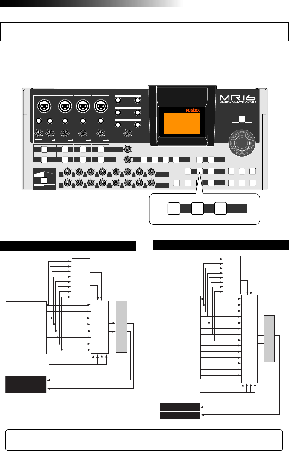
73
MR16 Owner’s Manual (Using effects)
Using the mastering effects
PEAK
GUITAR
MIN
DISTORTION
MAX LINE MIC
TRIM
INSERT/GUITAR
UNBAL
BALBALBALBAL
INPUT A INPUT B INPUT C INPUT D
VOLUME
MIN MAX
PEAK
LINE
TRIM
MIC
UNBAL
POWER
UNBAL
MIC
TRIM
LINE
PEAK
UNBAL
MIC
TRIM
LINE
PEAK
R
L
100
SIMULATION SIMULATION
AMP
MIC
010
LR
010
LR RL
100 010
LR
RL
100
RL
100
010
LR
UNDO/REDO
STORE
BOUNCE
MASTERING
BRIGHT
15/16 > STEREO WAV FILE
NATURAL
POWERFUL
B / OUTA / INPLAY MODEAUTO PUNCH
LOCATE
EFFECT
DELAYPLATEHALLROOM BOUNCE MODE
CONTRAST
TIMEBASE SELECT
RHYTHM GUIDE DIRECT LOCATE
EFFECT SEND
PAN
INPUT EQ
TO STEREO BUSS LEVEL
MENU / ENTER
MIN MAX
MIN MAX
REVERB / DELAY TIME
LSTEREO OUT R
1AUX OUT 2
1PHONES 2
DYNAMIC BRIT STACK
INPUT A INPUT B INPUT C INPUT D
MASTERING
BRIGHTNATURAL
POWERFUL
<Bouncing tracks 1 through 8 to tracks 9/10>
In addition to the bouncing examples above, you can also apply the mastering effects in the "Bounce 1-10 >11/12" and
"Bounce 1-12 >13/14" mode.
<Bouncing tracks 1 through 14 to tracks 15/16>
Track 8
Track 1
Track 9
Track 10
Mixing
Delay
or
Reverb
Playback
Bouncing
INPUT A ~ INPUT D
Record
Record
Mastering Effects
Playback
Track 1
Track 15
Track 16
Mixing
Delay
or
Reverb
Record
Playback
Bouncing
INPUT A ~ INPUT D
Track 14
Record
Mastering Effects
Playback
The MR16 provides the mastering effects dedicated for the stereo buses (L and R). You can
select the desired effect type using the [MASTERING] keys. The mastering effect can be used
when you bounce multiple tracks to two tracks or when you mix tracks 1 through 16 down
to stereo and record to an external master recorder.
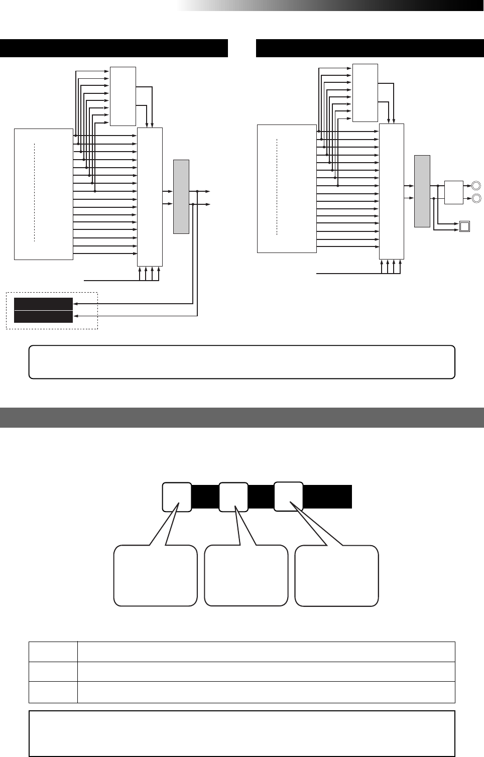
74
MR16 Owner’s Manual (Using effects)
POWERFUL
NATURAL
BRIGHT
<Note>:
By activating the mastering effect, the output level raises. Therefore, be careful of the
level change when monitoring via headphones or monitor speakers, as well as when adjusting
the recording level of an external recorder.
Adds power to the sound. Good for rock.
Slightly adds power to the sound. Good for acoustic music.
Add brightness to the sound. Good for use when the mixed sound is dark.
Each effect type has the following character. Select the appropriate type.
Three mastering effect types are available. You can select the desired type using the [MASTER-
ING] keys (POWERFUL, NATURAL and BRIGHT).
Selecting the desired effect type
MASTERING
BRIGHTNATURAL
POWERFUL
Select this when
you want to select
POWERFUL type
of the mastering
effects.
Select this when
you want to select
NATURAL type of
the mastering
effects.
Select this when
you want to select
BRIGHT type of
the mastering
effects.
See "Track bounce" on page 75 for details about track bounce which allows mixing multiple
tracks to stereo. See "Mixdown" on page 43 for details about mixdown.
Bouncing tracks 1 through 16 to a New song. Mixing tracks 1 through 16 down
Track 1
Mastering Effects
Track 15
Track 16
Mixing
Delay
or
Reverb
Record
Playback
Bouncing
INPUT A ~ INPUT D
Track 16
New Song
Stereo Out
Playback
Record
Track 1
Mastering Effects
Mixing
Delay
or
Reverb
Playback
INPUT A ~ INPUT D
Track 16
Stereo Out
D/A
DIGITAL OUT
Playback

75
MR16 Owner’s Manual (Track bouncing)
Track bouncing
This chapter describes track bouncing which is an important func-
tion in the recording process.
The track bouncing mixes several tracks and records onto other
two tracks. By using this function, you can record more sound
materials to the MR16 tracks.
Five track bouncing modes are available:
(1) Bouncing tracks 1 through 8 to tracks 9/10.
(2) Bouncing tracks 1 through 10 to tracks 11/12.
(3) Bouncing tracks 1 through 12 to tracks 13/14.
(4) Bouncing tracks 1 through 14 to tracks 15/16.
(5) Bouncing tracks 1 through 16 to tracks 15/16 of a new song.
In any mode, you can apply a reverb (or delay) to tracks 1 through
8 when bouncing to two tracks in stereo. Furthermore, you can
apply the mastering effect to the mixed signals.
You can also execute track bouncing while mixing sound sources
from inputs A through D.
The mixed data (stereo song data) bounced to tracks 15/16 can be
converted to a stereo WAV file and export to a PC for burning an
audio CD (CD-DA).
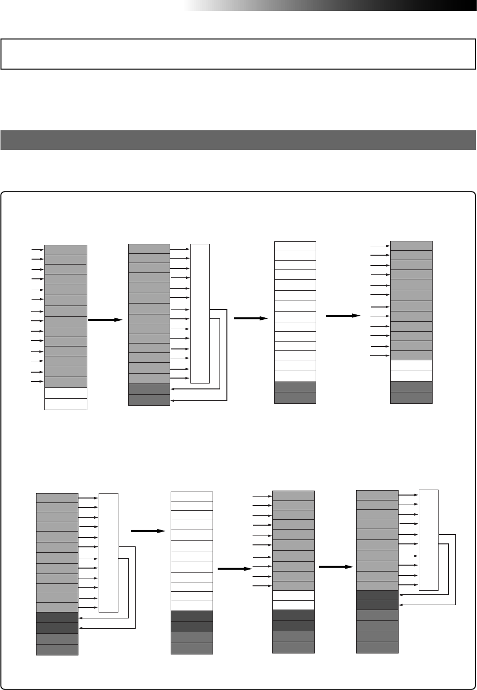
76
MR16 Owner’s Manual (Track bouncing)
You can record more than sixteen materials using the track bouncing function as shown in the
following example.
<Step 1>
Make recording to tracks
1 through 14.
<Step 2>
Bounce tracks 1 through 14
to tracks 15/16.
<Step 3>
Delete tracks 1 through
14.
<Step 5>
Bounce tracks 1 through 12 to
tracks 13/14.
Track 4
Track 3
Track 2
Track 1
Track 5
Track 6
Track 7
Track 8
Track 12
Track 11
Track 10
Track 9
Track 13
Track 14
Track 15
Track 16
Track 4
Track 3
Track 2
Track 1
Track 5
Track 6
Track 7
Track 8
Track 12
Track 11
Track 10
Track 9
Track 13
Track 14
Track 15
Track 16
Track 4
Track 3
Track 2
Track 1
Track 5
Track 6
Track 7
Track 8
Track 12
Track 11
Track 10
Track 9
Track 13
Track 14
Track 15
Track 16
<Step 6>
Delete tracks 1
through 12.
Before executing track bouncing, read "Track bouncing example" below and "Track bouncing signal
flow" on the next page.
Track bouncing example
Preliminary knowledge
Track 4
Track 3
Track 2
Track 1
Track 5
Track 6
Track 7
Track 8
Track 12
Track 11
Track 10
Track 9
Track 13
Track 14
Track 15
Track 16
Mixing
Track 4
Track 3
Track 2
Track 1
Track 5
Track 6
Track 7
Track 8
Track 12
Track 11
Track 10
Track 9
Track 13
Track 14
Track 15
Track 16
Track 4
Track 3
Track 2
Track 1
Track 5
Track 6
Track 7
Track 8
Track 12
Track 11
Track 10
Track 9
Track 13
Track 14
Track 15
Track 16
Mixing
Track 4
Track 3
Track 2
Track 1
Track 5
Track 6
Track 7
Track 8
Track 12
Track 11
Track 10
Track 9
Track 13
Track 14
Track 15
Track 16
Track 4
Track 3
Track 2
Track 1
Track 5
Track 6
Track 7
Track 8
Track 12
Track 11
Track 10
Track 9
Track 13
Track 14
Track 15
Track 16
Mixing
<Step 4>
Overdub new materials to
tracks 1 through 12.
<Step 7>
Overdub new materials
to tracks 1 through 10.
<Step 8>
Bounce tracks 1 through 10
to tracks 11/12.
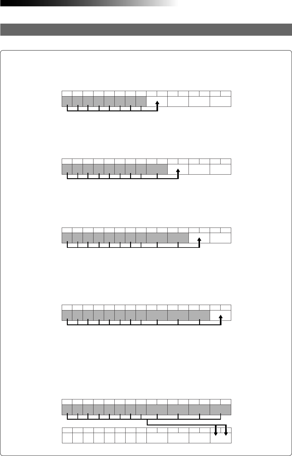
77
MR16 Owner’s Manual (Track bouncing)
Track bouncing modes
The five track bouncing modes described below are available.
"1-10 > 11/12" mode
In the "1-10 > 11/12" mode, tracks 1 through 10 are played back, mixed down to stereo, and
bounced to tracks 11/12. You can apply a reverb (or delay) to tracks 1 through 8, as well as
apply the mastering effect to the mixed signals.
"1-8 > 9/10" mode
In the "1-8 > 9/10" mode, tracks 1 through 8 are played back, mixed down to stereo, and
bounced to tracks 9/10. You can apply a reverb (or delay) to tracks 1 through 8, as well as
apply the mastering effect to the mixed signals.
"1-16 > New Song" mode
In the "1-16 > New Song" mode, tracks 1 through 16 are played back, mixed down to stereo, and
bounced to tracks 15/16 of the new song which is automatically created. By using this mode,
you can create a master song in the MR16 itself without the need of using an external master
recorder. You can apply a reverb (or delay) to tracks 1 through 8, as well as apply the master-
ing effect to the mixed signals. You can convert song data bounced to tracks 15/16 of the new
song to a stereo WAV file, which can be burned to an audio CD.
Trk 1 Trk 2 Trk 3 Trk 4 Trk 5 Trk 6 Trk 7 Trk 8 Trk 9 Trk 10 Trk 11 Trk 12 Trk 13 Trk 14 Trk 15 Trk 16
Trk 1 Trk 2 Trk 3 Trk 4 Trk 5 Trk 6 Trk 7 Trk 8 Trk 9 Trk 10 Trk 11 Trk 12 Trk 13 Trk 14 Trk 15 Trk 16
"1-12 > 13/14" mode
In the "1-12 > 13/14" mode, tracks 1 through 12 are played back, mixed down to stereo, and
bounced to tracks 13/14. You can apply a reverb (or delay) to tracks 1 through 8, as well as
apply the mastering effect to the mixed signals.
Trk 1 Trk 2 Trk 3 Trk 4 Trk 5 Trk 6 Trk 7 Trk 8 Trk 9 Trk 10 Trk 11 Trk 12 Trk 13 Trk 14 Trk 15 Trk 16
"1-14 > 15/16" mode
In the "1-14 > 15/16" mode, tracks 1 through 14 are played back, mixed down to stereo, and
bounced to tracks 15/16. You can apply a reverb (or delay) to tracks 1 through 8, as well as
apply the mastering effect to the mixed signals. You can convert song data bounced to tracks
15/16 to a stereo WAV file, which can be burned to an audio CD.
Trk 1 Trk 2 Trk 3 Trk 4 Trk 5 Trk 6 Trk 7 Trk 8 Trk 9 Trk 10 Trk 11 Trk 12 Trk 13 Trk 14 Trk 15 Trk 16
Trk 1 Trk 2 Trk 3 Trk 4 Trk 5 Trk 6 Trk 7 Trk 8 Trk 9 Trk 10 Trk 11 Trk 12 Trk 13 Trk 14 Trk 15 Trk 16
Trk 1 Trk 2 Trk 3 Trk 4 Trk 5 Trk 6 Trk 7 Trk 8 Trk 9 Trk 10 Trk 11 Trk 12 Trk 13 Trk 14 Trk 15 Trk 16
New Song
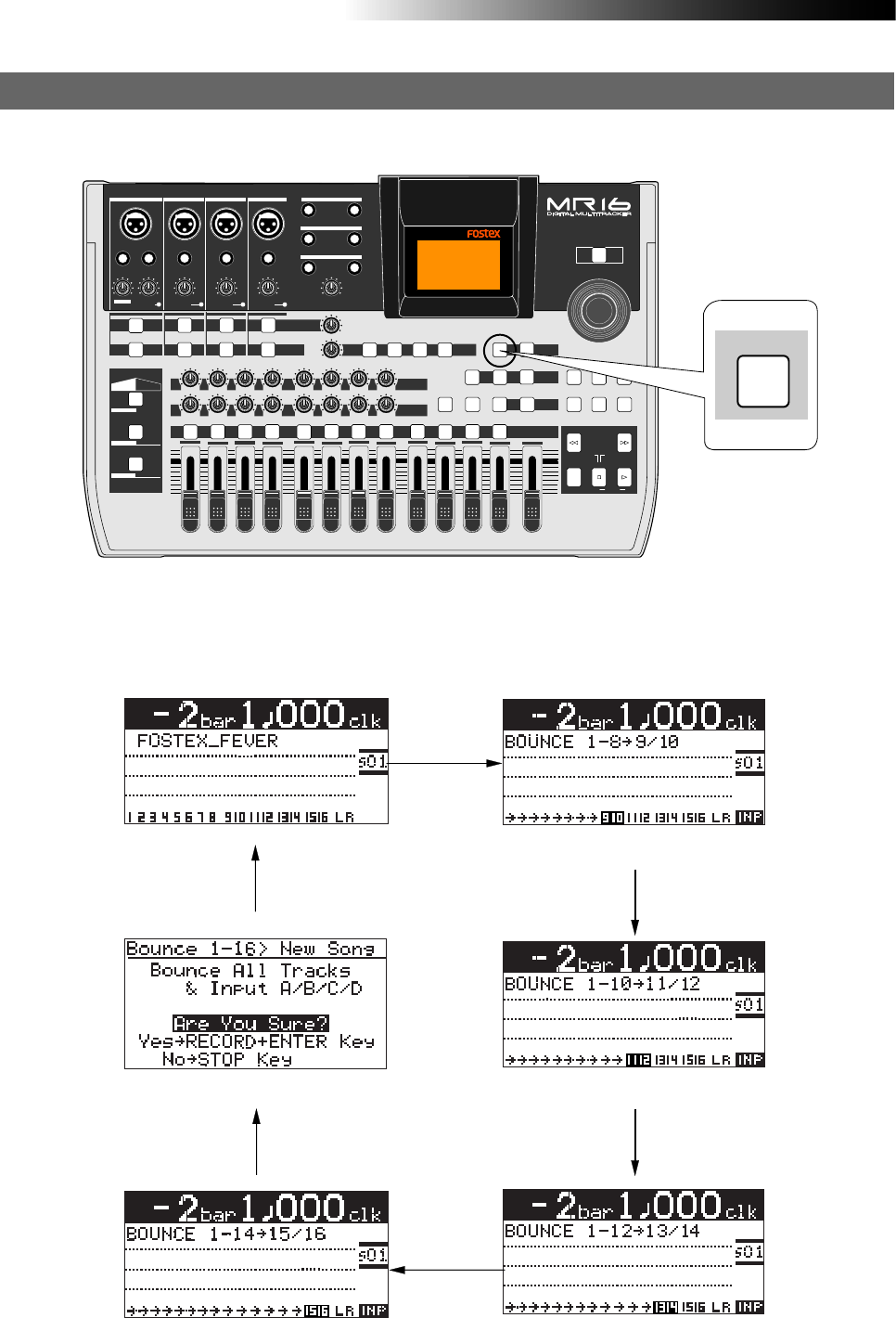
78
MR16 Owner’s Manual (Track bouncing)
You can select the desired track bouncing mode from among the five modes by pressing the
[BOUNCE MODE] key.
Selecting the track bouncing mode
PEAK
GUITAR
MIN
DISTORTION
MAX LINE MIC
TRIM
INSERT/GUITAR
UNBAL
BALBALBALBAL
INPUT A INPUT B INPUT C INPUT D
VOLUME
MIN MAX
PEAK
LINE
TRIM
MIC
UNBAL
POWER
UNBAL
MIC
TRIM
LINE
PEAK
UNBAL
MIC
TRIM
LINE
PEAK
MAX
MIN
1
R
L
100
SIMULATION SIMULATION
AMP
MIC
010
LR
010
LR
23
RL
100
4 8
010
LR
7
6
RL
100
RL
100
010
LR
5
MAX
MIN
MASTER
REC SELECT
RECORD STOP PLAY
REWIND F FWD
UNDO/REDO
STORE
LOCATE REC END
LOCATE ABS ZERO
A-B PLAY
BOUNCE
MASTERING
BRIGHT
15/16 > STEREO WAV FILE
NATURAL
POWERFUL
B / OUTA / INPLAY MODEAUTO PUNCH
LOCATE
EFFECT
DELAYPLATEHALLROOM BOUNCE MODE
CONTRAST
TIMEBASE SELECT
RHYTHM GUIDE DIRECT LOCATE
EFFECT SEND
PAN
INPUT EQ
TO STEREO BUSS LEVEL
9/10 11/12 13/14 15/16
ABC1 DEF2 GHI3 JKL4 MNO5 YZ9PQR6 +-_0STU7 VWX8 DELETE
MENU / ENTER
MIN MAX
MIN MAX
REVERB / DELAY TIME
LSTEREO OUT R
1AUX OUT 2
1PHONES 2
DYNAMIC BRIT STACK
CONDENSER US METAL
TUBE 60'S COMBO
INPUT A INPUT B INPUT C INPUT D
BOUNCE MODE
While the recorder is stopped, each press of the [BOUNCE MODE] key switches the bouncing
mode. The display shows the appropriate screen for the selected mode, while the [REC SELECT]
keys for the bounced tracks start flashing and the input monitor mode is enabled.
“1-14 > 15/16” mode “1-12 > 13/14” mode
“1-10 > 11/12” mode
“1-8 > 9/10” mode
“1-16 > New Song” mode
Bounce Mode: OFF
Press the [STOP] key.
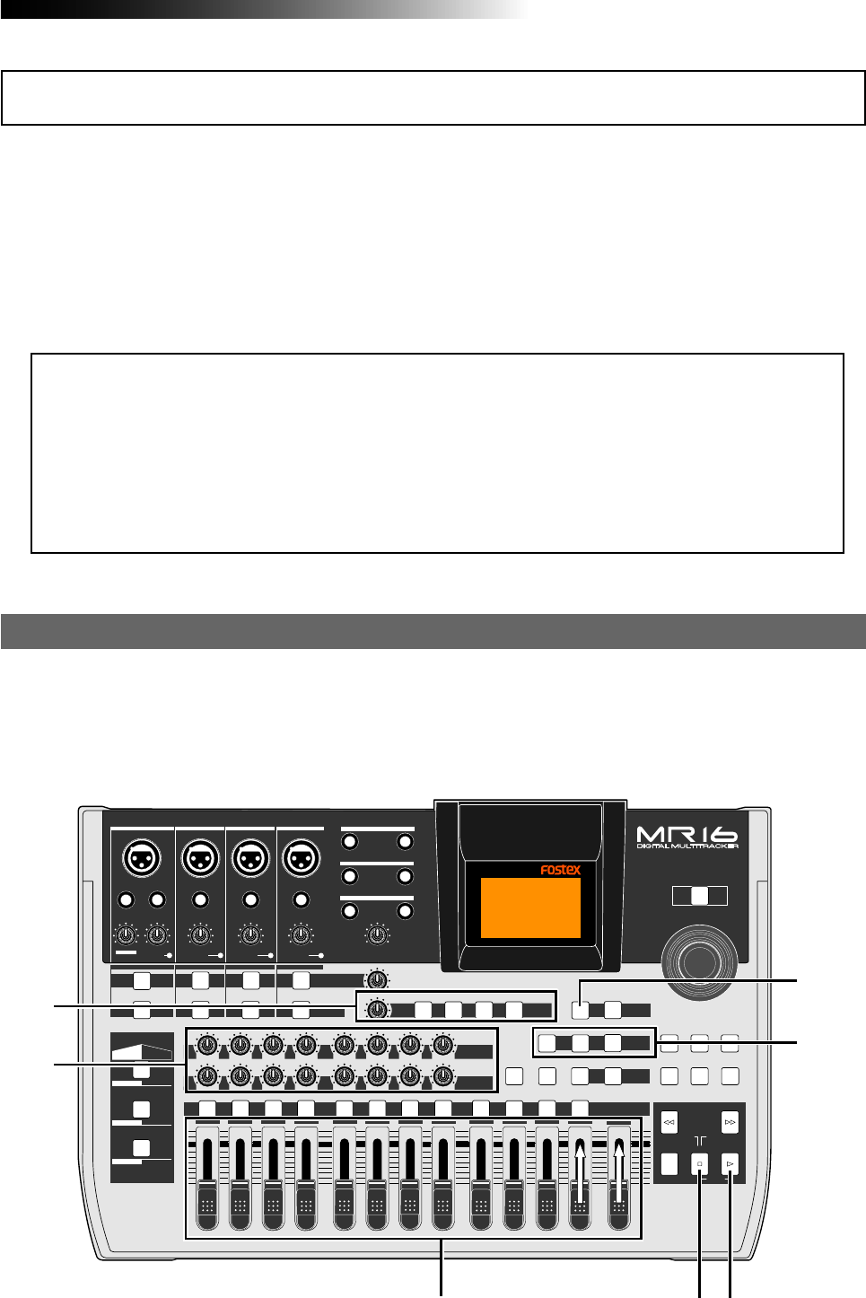
79
MR16 Owner’s Manual (Track bouncing)
Before executing track bouncing, you can rehearse it. While rehearsing track bouncing, you can
control the playback level, panning and reverb (or delay) send setting of each source track, as well as
apply the mastering effect to the mixed L/R signals. We recommend to make rehearsal thoroughly
until you are satisfied with the sound. The following assumes that the song you are going to execute
track bouncing is loaded.
Rehearsal of track bouncing
PEAK
GUITAR
MIN
DISTORTION
MAX LINE MIC
TRIM
INSERT/GUITAR
UNBAL
BALBALBALBAL
INPUT A INPUT B INPUT C INPUT D
VOLUME
MIN MAX
PEAK
LINE
TRIM
MIC
UNBAL
POWER
UNBAL
MIC
TRIM
LINE
PEAK
UNBAL
MIC
TRIM
LINE
PEAK
MAX
MIN
1
R
L
100
SIMULATION SIMULATION
AMP
MIC
010
LR
010
LR
23
RL
100
4 8
010
LR
7
6
RL
100
RL
100
010
LR
5
MAX
MIN
MASTER
REC SELECT
RECORD STOP PLAY
REWIND F FWD
UNDO/REDO
STORE
LOCATE REC END
LOCATE ABS ZERO
A-B PLAY
BOUNCE
MASTERING
BRIGHT
15/16 > STEREO WAV FILE
NATURAL
POWERFUL
B / OUTA / INPLAY MODEAUTO PUNCH
LOCATE
EFFECT
DELAYPLATEHALLROOM BOUNCE MODE
CONTRAST
TIMEBASE SELECT
RHYTHM GUIDE DIRECT LOCATE
EFFECT SEND
PAN
INPUT EQ
TO STEREO BUSS LEVEL
9/10 11/12 13/14 15/16
ABC1 DEF2 GHI3 JKL4 MNO5 YZ9PQR6 +-_0STU7 VWX8 DELETE
MENU / ENTER
MIN MAX
MIN MAX
REVERB / DELAY TIME
LSTEREO OUT R
1AUX OUT 2
1PHONES 2
DYNAMIC BRIT STACK
CONDENSER US METAL
TUBE 60'S COMBO
INPUT A INPUT B INPUT C INPUT D
4
2,4 53
2
1
4
The following describes how to mix tracks 1 through 14 and bounce to tracks 15/16 of the
current song.
You can bounce tracks 1 through 8 to tracks 9/10, tracks 1 through 10 to tracks 11/12, tracks 1
through 12 to tracks 13/14 in the similar manners.
Before executing actual track bouncing, we recommend you to rehearse the bouncing operation
repeatedly until you are satisfied with the setting of the level and balance of each playback track,
as well as delay/reverb setting for tracks 1 through 8.
Bounce tracks 1 through 14 to tracks 15/16
<Using track data bounced to tracks 15/16>
By converting track data (a pair of mono WAV files) bounced to tracks 15/16 to a stereo
WAV file, you can export it to a PC or burn it to an audio CD using the internal or external
CD-R/RW drive.
For details about exporting a WAV file to a PC, see page 107. For details about creating an
audio CD using the internal or external CD-R/RW drive, see the "How to use the CD-R/RW
drive" supplementary manual.
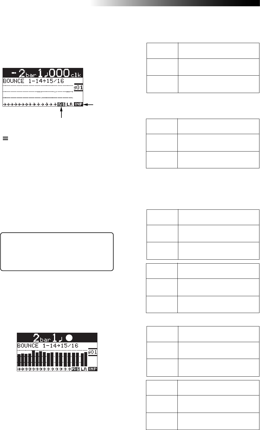
80
MR16 Owner’s Manual (Track bouncing)
5) After finishing rehearsal, press the [STOP] key
to stop the recorder and locate it to the
beginning of the song.
Do not move the controls and faders after
finishing rehearsal.
<Panning control>
You can freely adjust panning for tracks
1 through 8 using the PAN controls.
For example, a guitar to left, a vocal to
center, etc.
By raising the [PHONES VOL] control, you can
hear the signals bounced to tracks 15/16.
Use the [15/16] fader to control the monitor out-
put levels, and use the [MASTER] fader to ad-
just the recording levels of the bounced sig-
nals appropriately while checking meters 15/
16.
During rehearsal and actual track bouncing,
level meters on the screen show the following
signal levels.
1) Use the [BOUNCE MODE] key to select the
"1-14 > 15/16" bounce mode.
Selecting this bounce mode automatically arms
tracks 15/16 and changes the monitoring mode
for these tracks to input monitoring mode.
The display looks like this:
Flashing
2) Raise the [9/10] fader and [MASTER] fader to the
"" position. Set all the other track faders down
to the minimum position.
Playback levels of tracks 1 through
8 for bouncing.
Faders
1 through 8
Lighting
During rehearsal and actual track bouncing,
the track faders and [MASTER] fader control
the following signals.
[MASTER]
fader
Fader 9/10
Recording master level of tracks
9/10.
Monitor levels of tracks 9/10.
3) Press the [PLAY] key to start playback from the
beginning of the song.
4) While playing back the song, adjust playback
levels of tracks 1 through 14 using the track
faders.
You can apply the delay/reverb to tracks 1
through 8 and the mastering effects to the
stereo L and R signals. See "Using effects" on
page 65 for details about the delay/reverb and
mastering effects.
• In the "1-10 > 11/12" mode
Playback levels of tracks 1 through
10 for bouncing.
Faders
1 through 10
[MASTER]
fader
Fader 11/12
Recording master level of tracks
11/12.
Monitor levels of tracks 11/12.
Playback levels of tracks 1 through
10.
Meters
1 through 10
Meters
L and R
Meters 11/12
Monitor output levels of STEREO
OUT (L, R).
Recording levels of tracks 11/12.
• In the "1-8 > 9/10" mode
Playback levels of tracks 1 through
14 for bouncing.
Faders
1 through 14
[MASTER]
fader
Fader 15/16
Recording master level of tracks
15/16.
Monitor levels of tracks 15/16.
Playback levels of tracks 1 through
14.
Meters
1 through 14
Meters
L and R
Meters 15/16
Monitor output levels of STEREO
OUT (L, R).
Recording levels of tracks 15/16.
The following tables show the signals controlled
by the faders and the levels displayed by the
meters in other track bouncing modes.
Playback levels of tracks 1 through
8.
Meters
1 through 8
Meters
L and R
Meters 9/10
Monitor output levels of STEREO
OUT (L, R).
Recording levels of tracks 9/10.
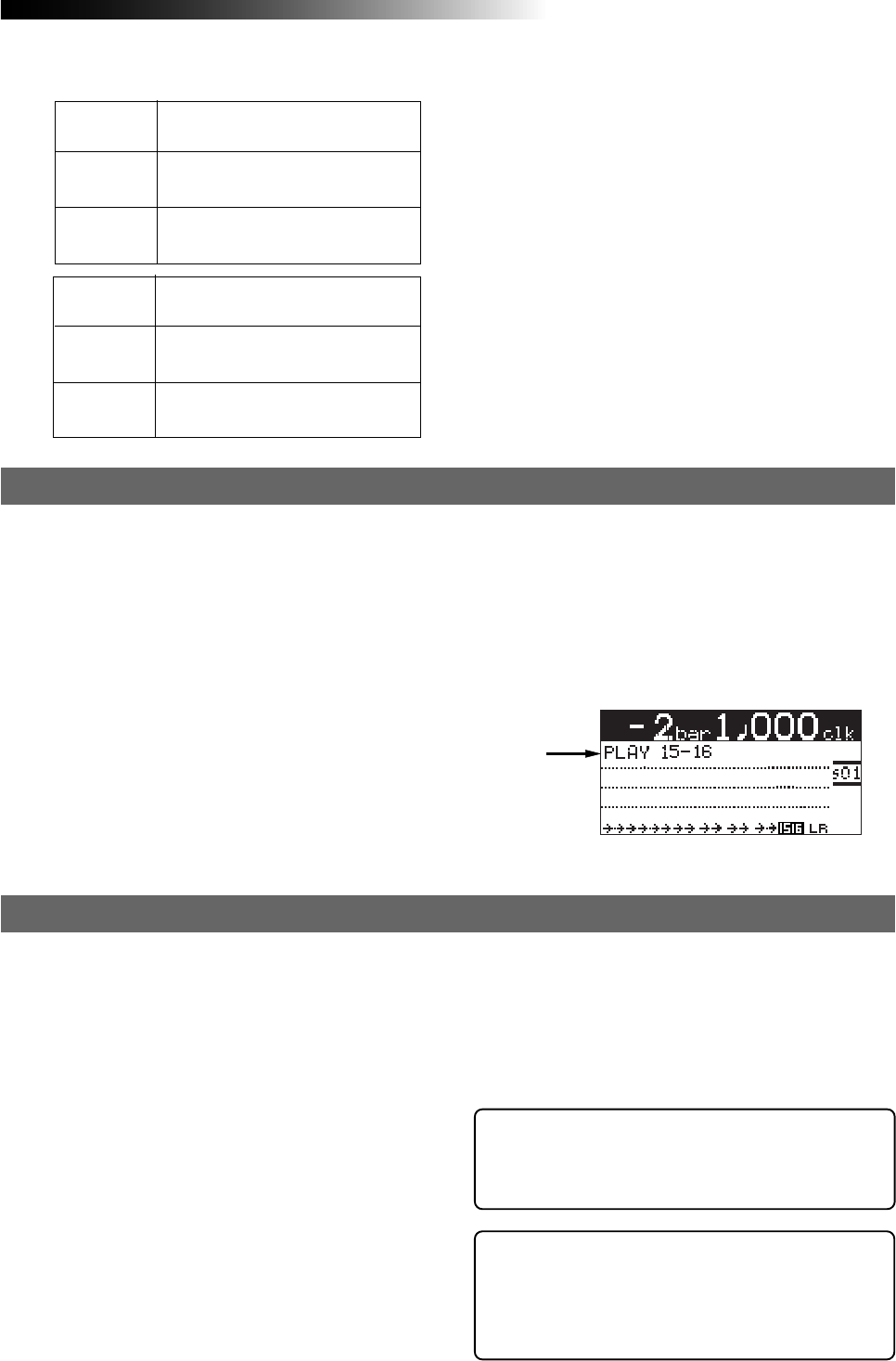
81
MR16 Owner’s Manual (Track bouncing)
2) Press the [PLAY] key while holding down the
[RECORD] key.
Track bouncing starts with the effect/level
settings made in the rehearsal mode.
The mixed signals are recorded onto tracks 15/
16.
3) After track bouncing completes, press the [STOP]
key to stop the recorder.
1) Press the [REWIND] key while holding down the
[STOP] key to locate the recorder to the
beginning of the song.
2) Make sure that the input monitoring mode is
turned off.
3) Press the [PLAY] key to start playback from the
beginning of the song.
4) Use the [15/16] fader to control the playback level
of the bounced signals.
By playing back the recorder while the bounce
mode ("1-14 > 15/16") is active, only tracks 15/
16 can be monitored.
In this condition, you cannot monitor playback
signals of tracks 1 through 14 even if you raise
their faders.
After finishing rehearsal, let's carry out actual track bouncing. Make sure that the recorder stops
at the beginning of the song.
You can check the bounced signals while the bounce mode is active.
Actual track bouncing
Checking the bounced signals on tracks 15/16
1) Before carrying out actual track bouncing, make
sure that the bounce mode is selected to
"1-14 > 15/16".
• In the "1-12 > 13/14" mode
Playback levels of tracks 1 through
12 for bouncing.
Faders
1 through 12
[MASTER]
fader
Fader 13/14
Recording master level of tracks
9/10.
Monitor levels of tracks 13/14.
Playback levels of tracks 1 through
12.
Meters
1 through 12
Meters
L and R
Meters 13/14
Monitor output levels of STEREO
OUT (L, R).
Recording levels of tracks 13/14.
Stopping the recorder automatically turns off
the input monitoring mode of tracks 15/16,
while the display changes to show the screen
below, prompting you to play back tracks 15/
16 for confirming the result.
<Auto punch in/out of track bouncing>
You can bounce only the desired part (between
the IN and OUT points) using the auto punch
in/out function (see page 87).
<Track bouncing while mixing signals from [INPUT
A] through [INPUT D]>
When you bounce tracks 1 through 8 to tracks
9/10, you can also mix signals from [INPUT A]
through [INPUT D] together (see page 85).
If you want to redo track bouncing, use the
undo function to go back to the condition
before carrying out track bouncing, and try
again.
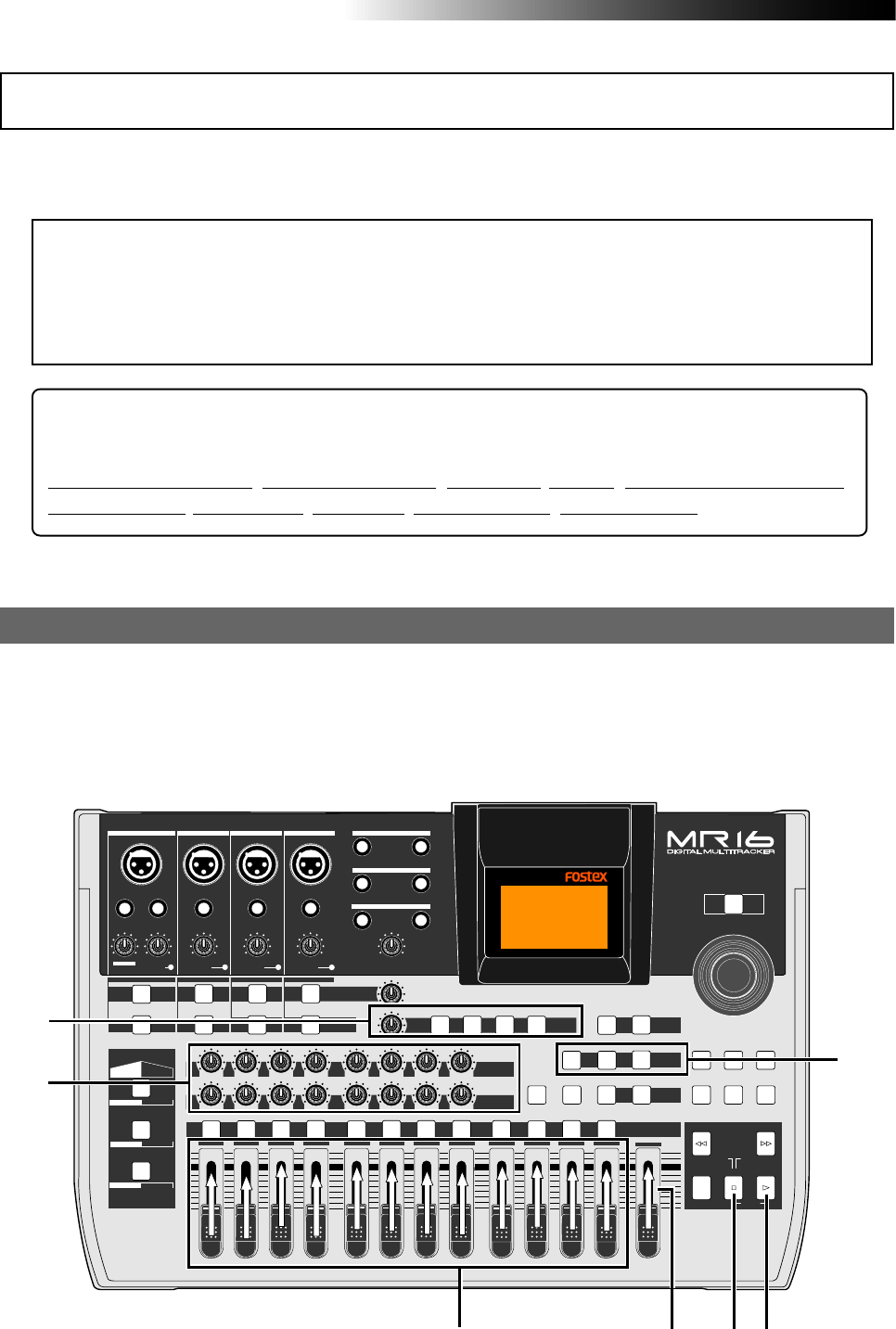
82
MR16 Owner’s Manual (Track bouncing)
You can bounce tracks 1 through 16 to tracks 15/16 of a new song. A new song is automatically
created when executing track bouncing (<Note>: In the “1-16 > NEW SONG” mode, you cannot bounce
the desired part of a song by using the track bouncing and auto punch in/out functions together).
Before executing track bouncing, you can rehearse it. While rehearsing track bouncing, you can
control the playback level, panning and reverb (or delay) send setting of each source track, as
well as apply the mastering effect to the mixed L/R signals.
We recommend to make rehearsal thoroughly until you are satisfied with the sound. The follow-
ing assumes that the song you are going to execute track bouncing is loaded.
Rehearsal of track bouncing
Bouncing tracks 1 through 16 to a new song
<Using bounced track data>
By converting bounced track data (in two mono WAV files) to a stereo WAV file, you can export
it to a personal computer or create an original audio CD using the internal (or an external) CD-R/
RW drive. See page 107 for details about how to export a file to a personal computer. See the
supplementary manual "How to use the CD-R/RW drive" for details about burning an audio CD
using the internal (or an external) CD-R/RW drive.
PEAK
GUITAR
MIN
DISTORTION
MAX LINE MIC
TRIM
INSERT/GUITAR
UNBAL
BALBALBALBAL
INPUT A INPUT B INPUT C INPUT D
VOLUME
MIN MAX
PEAK
LINE
TRIM
MIC
UNBAL
POWER
UNBAL
MIC
TRIM
LINE
PEAK
UNBAL
MIC
TRIM
LINE
PEAK
MAX
MIN
1
R
L
100
SIMULATION SIMULATION
AMP
MIC
010
LR
010
LR
23
RL
100
4 8
010
LR
7
6
RL
100
RL
100
010
LR
5
MAX
MIN
MASTER
REC SELECT
RECORD STOP PLAY
REWIND F FWD
UNDO/REDO
STORE
LOCATE REC END
LOCATE ABS ZERO
A-B PLAY
BOUNCE
MASTERING
BRIGHT
15/16 > STEREO WAV FILE
NATURAL
POWERFUL
B / OUTA / INPLAY MODEAUTO PUNCH
LOCATE
EFFECT
DELAYPLATEHALLROOM BOUNCE MODE
CONTRAST
TIMEBASE SELECT
RHYTHM GUIDE DIRECT LOCATE
EFFECT SEND
PAN
INPUT EQ
TO STEREO BUSS LEVEL
9/10 11/12 13/14 15/16
ABC1 DEF2 GHI3 JKL4 MNO5 YZ9PQR6 +-_0STU7 VWX8 DELETE
MENU / ENTER
MIN MAX
MIN MAX
REVERB / DELAY TIME
LSTEREO OUT R
1AUX OUT 2
1PHONES 2
DYNAMIC BRIT STACK
CONDENSER US METAL
TUBE 60'S COMBO
INPUT A INPUT B INPUT C INPUT D
3
1,3 42
3
3
1,3
<Hint>: When bouncing tracks to a new song, the settings for the following parameters are
copied to the new song.
Rhythm guide On/Off, Internal click level, Signature, Tempo, Conductor map On/Off,
Signature map, Tempo map, Bar offset, Locate A point, Locate B point
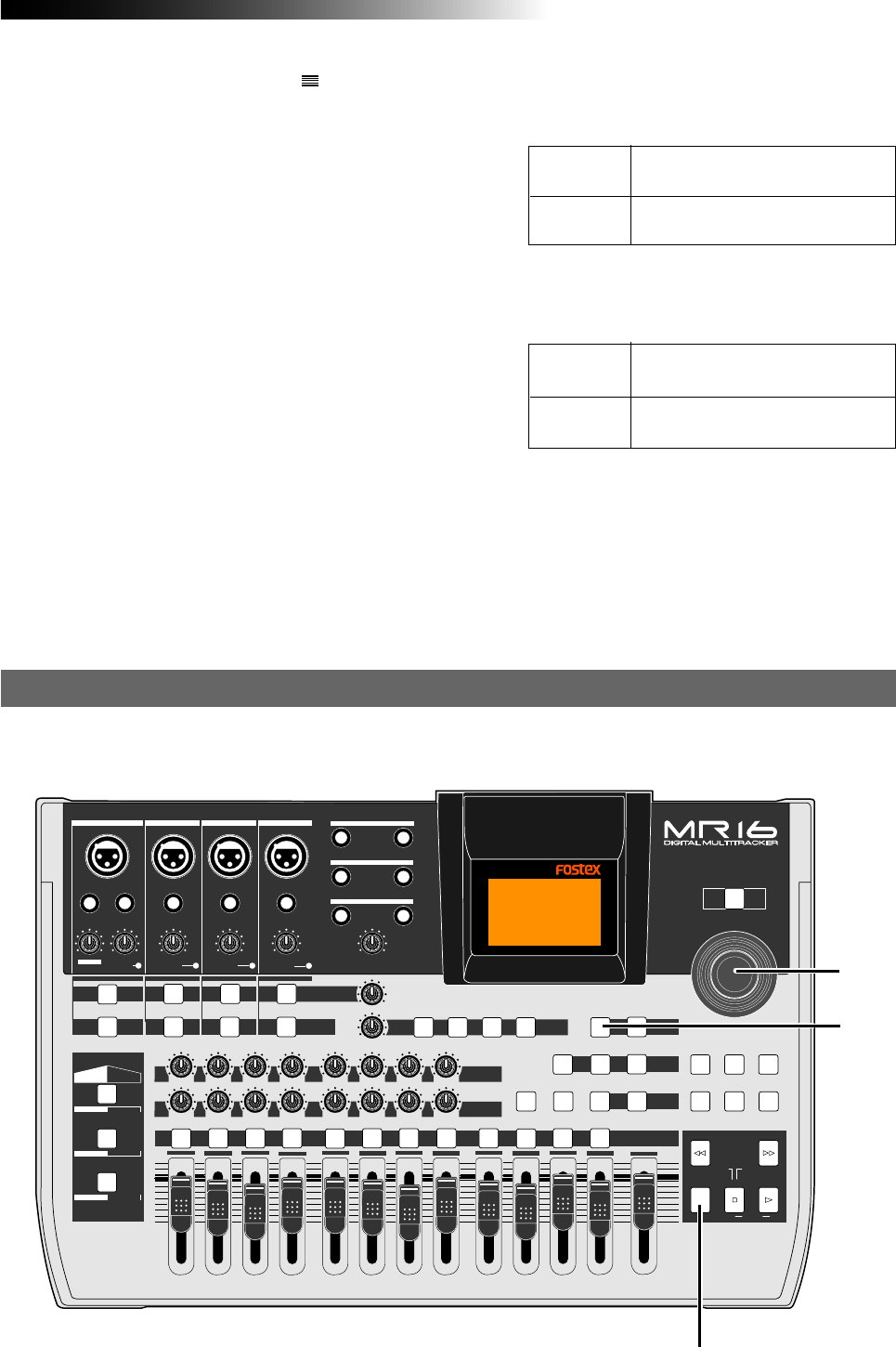
83
MR16 Owner’s Manual (Track bouncing)
After finishing rehearsal, let's carry out actual track bouncing.
Actual track bouncing
4) After finishing rehearsal, press the [STOP] key
to stop the recorder and locate it to the
beginning of the song.
Do not move the controls and faders after fin-
ishing rehearsal.
During rehearsal and actual track bouncing,
the level meters on the screen show the fol-
lowing signal levels.
1) Raise the [MASTER] fader to the " " position.
Set all the track faders down to the minimum
position.
2) Press the [PLAY] key to start playback from the
beginning of the song.
3) While playing back the song, adjust playback levels
of tracks 1 through 16 using the track faders.
You can also adjust panning for tracks 1 through
8 and apply the reverb or delay to these tracks,
as well as apply the mastering effect to the mixed
sound.
Use the track faders (1 through 16) to control
the track output levels, and use the [MASTER]
fader to adjust the master recording levels of
the bounced signals appropriately while
checking meters L/R.
See "Using effects" on page 65 for details about
the delay/reverb and mastering effects.
By raising the [PHONES VOL] control, you can
hear the bounced signals.
Playback levels of tracks 1 through 16
for bouncing.
Faders
1 through 16
[MASTER]
fader Recording master levels of bouncing.
Playback levels of tracks 1 through 16.
Meters
1 through 16
Meters
L and R
Output levels of STEREO OUT (= re-
cording levels of bouncing)
During rehearsal and actual track bouncing, the
track faders and [MASTER] fader control the fol-
lowing signal levels.
PEAK
GUITAR
MIN
DISTORTION
MAX LINE MIC
TRIM
INSERT/GUITAR
UNBAL
BALBALBALBAL
INPUT A INPUT B INPUT C INPUT D
VOLUME
MIN MAX
PEAK
LINE
TRIM
MIC
UNBAL
POWER
UNBAL
MIC
TRIM
LINE
PEAK
UNBAL
MIC
TRIM
LINE
PEAK
MAX
MIN
1
R
L
100
SIMULATION SIMULATION
AMP
MIC
010
LR
010
LR
23
RL
100
4 8
010
LR
7
6
RL
100
RL
100
010
LR
5
MAX
MIN
MASTER
REC SELECT
RECORD STOP PLAY
REWIND F FWD
UNDO/REDO
STORE
LOCATE REC END
LOCATE ABS ZERO
A-B PLAY
BOUNCE
MASTERING
BRIGHT
15/16 > STEREO WAV FILE
NATURAL
POWERFUL
B / OUTA / INPLAY MODEAUTO PUNCH
LOCATE
EFFECT
DELAYPLATEHALLROOM BOUNCE MODE
CONTRAST
TIMEBASE SELECT
RHYTHM GUIDE DIRECT LOCATE
EFFECT SEND
PAN
INPUT EQ
TO STEREO BUSS LEVEL
9/10 11/12 13/14 15/16
ABC1 DEF2 GHI3 JKL4 MNO5 YZ9PQR6 +-_0STU7 VWX8 DELETE
MENU / ENTER
MIN MAX
MIN MAX
REVERB / DELAY TIME
LSTEREO OUT R
1AUX OUT 2
1PHONES 2
DYNAMIC BRIT STACK
CONDENSER US METAL
TUBE 60'S COMBO
INPUT A INPUT B INPUT C INPUT D
2
1
2
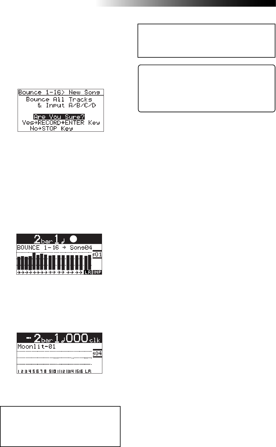
84
MR16 Owner’s Manual (Track bouncing)
1) While the recorder is stopped, press the
[1-8 > NEW SONG] key.
2) Press the [MENU/ENTER] knob while holding down
the [RECORD] key.
<Note>:
To cancel track bouncing in the
middle, press the [
STOP
] key. Pressing the
[
STOP
] key automatically deletes the new
song created in step 2 above and turns off
the bounce mode.
<Note>:
When you are going to execute track bounc-
ing, if there is not enough space on the hard disk
or 99 songs already exist on the disk, a warning
message appears and the operation is canceled.
<Track bouncing while mixing signals from [INPUT A]
through [INPUT D]>
When you bounce tracks 1 through 16 to tracks
15/16 of the new song, you can also mix signals
from [INPUT A] through [INPUT D] together (see next
page).
You can check the result by following the pro-
cedure described in “Checking the bounced
signals on tracks 15/16” on page 81.
Track bouncing starts. The mixed (bounced) sig-
nals are recorded to tracks 15/16 of a new song.
The screen example below shows that tracks 1
through 16 of Song01 (whose name is “Moon-
lit”) is now being bounced to tracks 15/16 of the
new song (Song04).
Meters 1 through 16 show the playback levels of
tracks 1 through 16, while the L and R meters
shows the recording levels of tracks 15/16 of
Song04.
The [1-16 > NEW SONG] key lights up and the
display shows the screen below. If you execute
track bouncing, press the [MENU/ENTER] knob
while holding down the [RECORD] key.
If you cancel track bouncing, press the [STOP]
key.
When track bouncing to a new song completes,
the recorder automatically stops and the dis-
play shows the home screen of the new song.
The song name of the new song is given by the
name of the original song with “-**” (** is a
two-digit number).
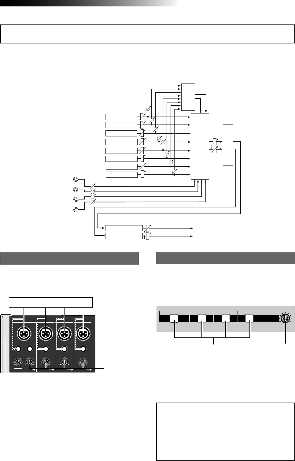
85
MR16 Owner’s Manual (Track bouncing)
The MR16 can mix input signals of [INPUT A] through [INPUT D].
The following diagram shows an example of mixing signals of INPUT A through INPUT D when
bouncing tracks 1 through 8 to tracks 9/10. As you can see, the signals of INPUT A through
INPUT D are mixed to the L/R stereo buss together with the bounced signals.
Before starting track bouncing, connect the desired
sound source(s) to any desired input(s) between
INPUT A and INPUT D.
Connecting sound sources to INPUT A through INPUT D
Adjust the input level of each input using the [TRIM]
control to match the balance with the bounced
track levels.
Also, you can adjust panning of each input for ste-
reo mix. See the next page for details about how to
set panning.
To send an input signal of any of the [INPUT A]
through [INPUT D] to the stereo L/R buss, turn on
the corresponding [TO STEREO BUSS] key and ad-
just the send level using the [LEVEL] control.
[TO STEREO BUSS] key setting
[TRIM] control
[TO STEREO BUSS] key
When the [TO STEREO BUSS] key is turned on, the
key illuminates in green. That is, when the key il-
luminates, input signal is sent to the stereo L/R
buss. (Note that when the key flashes, the corre-
sponding input is assigned to any recording track.)
<Note>:
If you press the [
TO STEREO BUSS
] key
when make recording other than track bounc-
ing, the key lamp may flash. This shows the
input signal is routed to the armed track. That
is, the input signal will be recorded to the
armed track, in stead of mixed to the stereo
buss.
Mixing signals of inputs A through D
Sound source (s)
Track 4
Track 3
Track 2
Track 1
Mastering Effect
Track 5
Track 6
Mixing
Playback
Delay
or
Reverb
Bouncing
Track 9
Track 10
STEREO OUT (L, R)
INPUT A
INPUT B
INPUT C
INPUT D
TRIM
Track 7
Track 8
Playback
Playback
Playback
Playback
Playback
Playback
Playback
Recording
Recording
PEAK
GUITAR
MIN
DISTORTION
MAX LINE MIC
TRIM
INSERT/GUITAR
UNBAL
BALBALBALBAL
INPUT A INPUT B INPUT C INPUT D
PEAK
LINE
TRIM
MIC
UNBAL UNBAL
MIC
TRIM
LINE
PEAK
UNBAL
MIC
TRIM
LINE
PEAK
TO STEREO BUSS LEVEL
MIN MAX
[LEVEL] control
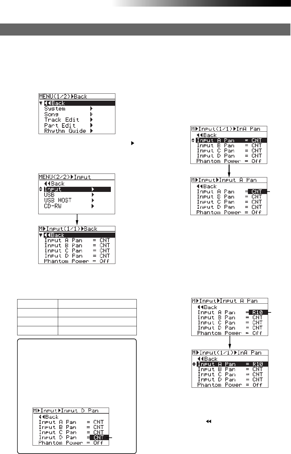
86
MR16 Owner’s Manual (Track bouncing)
The default panning settings are as below.
You can set each input to the desired panning
position from L10 (hard left) to R10 (hard
right).
Input A CNT (center position)
Input B CNT (center position)
Input C CNT (center position)
Input D CNT (center position)
3) Rotate the [MENU/ENTER] knob to select the
desired item (any one of "Input A Pan" through
"Input D Pan"), and press the [MENU/ENTER] knob.
You can select the desired panning value from
among R01 through R10 and L01 through L10,
as well as "CNT" (center).
4) Rotate the [MENU/ENTER] knob to select the
desired value, and press the [MENU/ENTER] knob.
The panning is set and the display returns to the
previous screen.
In the screen example below, "Input A Pan" is set
to "R10".
You can also make panning setting of another
input in the same manner as above.
5) Press the [STOP] key to exit the menu mode.
By selecting " Back" and pressing the
[MENU/ENTER] knob, the display returns to the
previous screen.
Therefore, you can also exit the menu mode
by repeating this operation.
<Tip>: You can directly access to the input
menu screen by a long press of the [TO STE-
REO BUSS] key of the desired input chan-
nel. On the input menu screen accessed in
this way, the panning setting item for the
corresponding input is highlighted.
For example, a long press of the [TO STE-
REO BUSS] key of [INPUT D] directly accesses
to the screen shown below.
Panning setting for INPUT A through INPUT D
1) While the recorder is stopped, press the
[MENU/ENTER] knob to enter the menu mode.
The display now shows the first page of the
menu selection screen.
2) Rotate the [MENU/ENTER] knob to select "Input "
on the second page, and press the [MENU/ENTER]
knob.
The display now shows the input menu screen.
You can independently set panning for each of INPUT A through INPUT D.
Each input signal is positioned in the mix according to the panning setting here.
The display shows the screen for making pan-
ning setting of the selected input. The current
setting flashes.
In the screen example below, "Input A Pan" is se-
lected and the default "CNT" is flashing.
Flashing
Flashing
Flashing
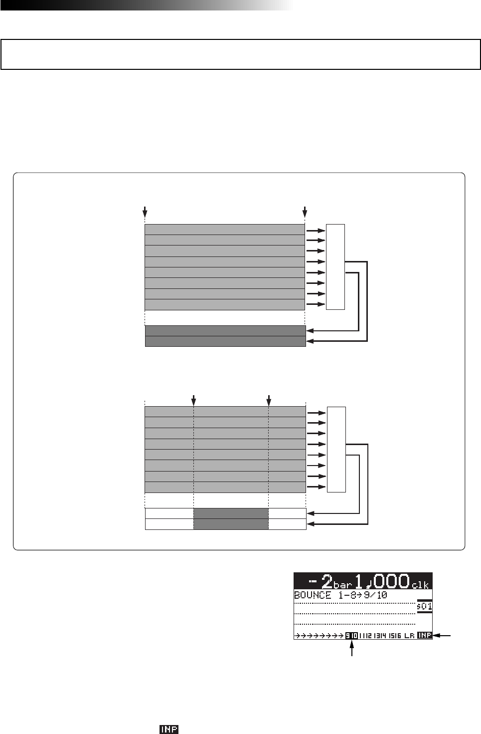
87
MR16 Owner’s Manual (Track bouncing)
Typically, bouncing is executed from the beginning to the end of a song, as shown in Figure 1
below. However, you can bounce only the desired part by using the track bouncing and punch
in/out functions together. The following assumes that the song you are going to execute track
bouncing is loaded and you finished rehearsal of track bouncing.
The following procedure shows the example of bouncing the desired part of a song in the "Bounce
1-8 > 9/10" mode (<Note>: In the “1-16 > NEW SONG” mode, you cannot bounce the desired part of a
song by using the track bouncing and auto punch in/out functions together).
1) Set the punch-in and punch-out points (see page
62).
By pressing the [PLAY] key while holding down
the [STOP] key, you can play back the part
between the punch-in and punch-out points
(see page 48).
2) Locate the recorder to a position before the
punch-in point.
3) Press the [BOUNCE MODE] key to set the bounce
mode to "1-8 > 9/10".
When setting the bounce mode to
"1-8 > 9/10", tracks 9/10 automatically enter
the input monitor mode and " " lights on
the home screen.
TRK 1
TRK 2
TRK 3
TRK 4
TRK 5
TRK 6
TRK 9
TRK 10
ABS ZERO REC END
Mixing
TRK 7
TRK 8
TRK 1
TRK 2
TRK 3
TRK 4
TRK 5
TRK 6
TRK 9
TRK 10
Mixing
TRK 7
TRK 8
Punch In point
(Locate A Point) Punch Out point
(Locate B Point)
Typical bouncing (Fig. 1)
Bouncing the desired part (Fig. 2)
4) Press the [AUTO PUNCH] key to activate the auto
punch mode.
Lighting
Flashing
Bouncing the desired part of a song
The [AUTO PUNCH] key is lit when the auto
punch mode is active.
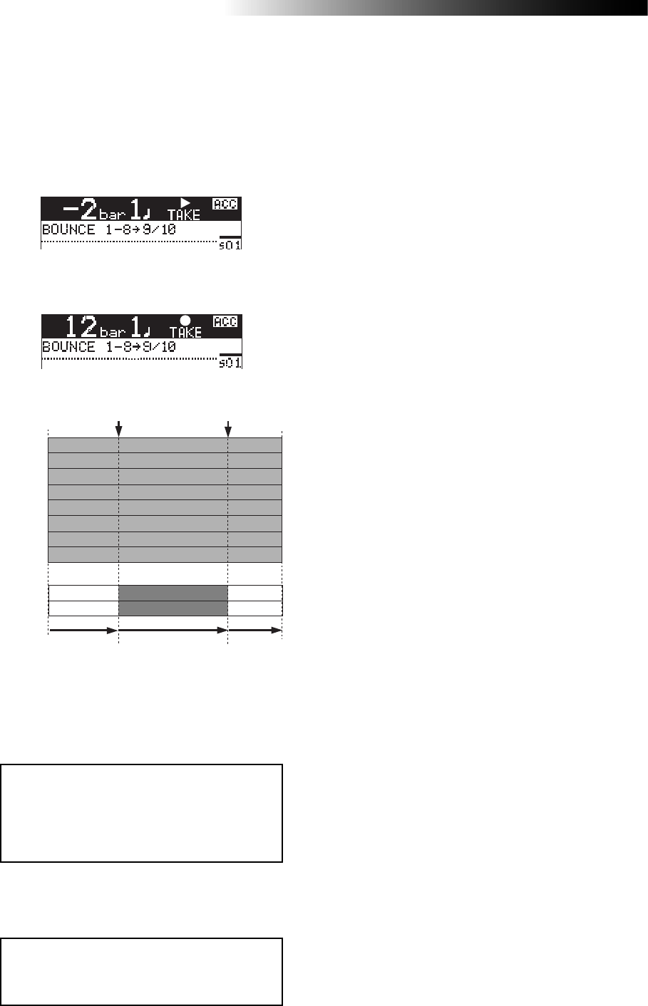
88
MR16 Owner’s Manual (Track bouncing)
5) Press the [RECORD] key while holding down the
[PLAY] key.
"TAKE" is shown in the upper part of the screen
and the recorder starts playback.
It automatically starts recording (bouncing)
when it reaches the punch-in point.
TRK 1
TRK 2
TRK 3
TRK 4
TRK 5
TRK 6
TRK 9
TRK 10
TRK 7
TRK 8
Punch In point
(Locate A Point) Punch Out point
(Locate B Point)
Play back
(Input Monitor) Recording
(Bouncing) Play back
The recorder stops recording (bouncing) at the
punch-out point and returns to playback, while
the auto punch mode exits and "TAKE" in the
screen turns off.
6) Press the [STOP] key to stop the recorder.
Check the result by playing back the bounced
tracks, as described earlier.
<Note>:
During playback in the operation
above, you cannot monitor the sound. You
can monitor the sound (bounced sound)
only during recording between punch-in
and punch-out points.
<Note>:
If you are not satisfied with the
result, press the [
UNDO/REDO
] key to redo
the operation.
Before the punch-in point
Between the punch-in and
punch-out points

89
MR16 Owner’s Manual (Rhythm guide function)
Rhythm guide function
The MR16 offers the rhythm guide function, which allows outputting the
rhythm guide click during recording.
This chapter describes how to output the rhythm guide, set the time
signature/tempo and create the conductor map.
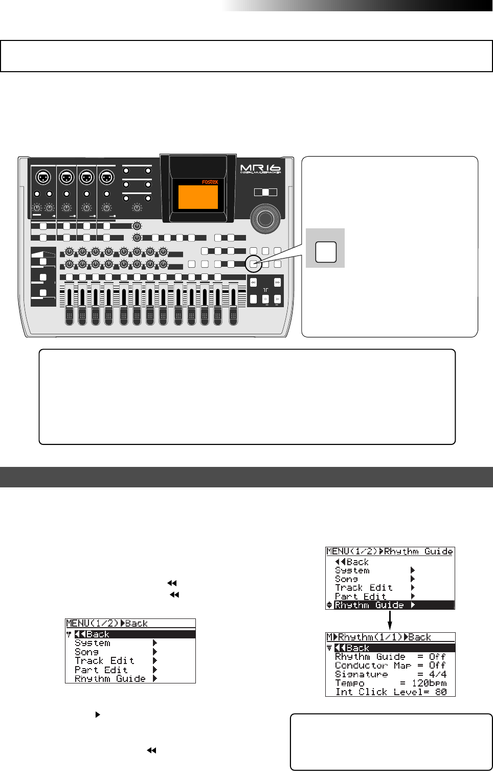
90
MR16 Owner’s Manual (Rhythm guide function)
The MR16 provides the metronome function which can output the rhythm guide click during
recording. You can easily output the guide click from the [STEREO OUT L, R] jacks by pressing the
[RHYTHM GUIDE] key on the top panel. Two types of the rhythm guide are available: one has the
constant time signature/tempo throughout a song, while the other has the programmed time
signature/tempo map.
PEAK
GUITAR
MIN
DISTORTION
MAX LINE MIC
TRIM
INSERT/GUITAR
UNBAL
BALBALBALBAL
INPUT A INPUT B INPUT C INPUT D
VOLUME
MIN MAX
PEAK
LINE
TRIM
MIC
UNBAL
POWER
UNBAL
MIC
TRIM
LINE
PEAK
UNBAL
MIC
TRIM
LINE
PEAK
MAX
MIN
1
R
L
100
SIMULATION SIMULATION
AMP
MIC
010
LR
010
LR
23
RL
100
4 8
010
LR
7
6
RL
100
RL
100
010
LR
5
MAX
MIN
MASTER
REC SELECT
RECORD STOP PLAY
REWIND F FWD
UNDO/REDO
STORE
LOCATE REC END
LOCATE ABS ZERO
A-B PLAY
BOUNCE
MASTERING
BRIGHT
15/16 > STEREO WAV FILE
NATURAL
POWERFUL
B / OUTA / INPLAY MODEAUTO PUNCH
LOCATE
EFFECT
DELAYPLATEHALLROOM BOUNCE MODE
CONTRAST
TIMEBASE SELECT
RHYTHM GUIDE DIRECT LOCATE
EFFECT SEND
PAN
INPUT EQ
TO STEREO BUSS LEVEL
9/10 11/12 13/14 15/16
ABC1 DEF2 GHI3 JKL4 MNO5 YZ9PQR6 +-_0STU7 VWX8 DELETE
MENU / ENTER
MIN MAX
MIN MAX
REVERB / DELAY TIME
LSTEREO OUT R
1AUX OUT 2
1PHONES 2
DYNAMIC BRIT STACK
CONDENSER US METAL
TUBE 60'S COMBO
INPUT A INPUT B INPUT C INPUT D
GUIDE
RHYTHUM
Setting the time signature and tempo
To output the rhythm guide
click, turn on the [RHYTHM
GUIDE] key. By default, the
guide click is output at time
signature=4/4, tempo=120.
You can output the rhythm
guide click according to the
desired constant time signa-
ture and tempo, as well as
the programmed rhythm
guide click based on the
conductor map.
You can set the default rhythm guide (time signature: 4/4, tempo: 120), output level, etc. using
the "Rhythm Guide" menu in the menu mode.
2) Rotate the [MENU/ENTER] knob to select
"Rhythm Guide ", and press the [MENU/ENTER]
knob.
The display now shows the screen for setting
the rhythm guide, where " Back" is
highlighted.
1) While the recorder is stopped, press the
[MENU/ENTER] knob to enter the menu mode.
The display now shows the first page of the
menu selection screen, where " Back" is
highlighted initially (selecting " Back"
returns to the previous screen).
Tip!: While the home screen is shown and
the recorder is stopped, long press of the
[RHYTHM GUIDE] key directly brings up the
screen for setting the rhythm guide.
When recording starts, the MR16 simultaneously starts feeding the rhythm guide
click from the [STEREO OUT L, R] jacks at the selected level (the default is 80).
Note that the rhythm guide click is not output during track bouncing. The output
level of the rhythm guide click is shown on the L and R level meters.
Note that you can monitor the rhythm guide click via headphones or (a) monitor
speaker(s). You cannot record the rhythm guide click to any MR16 track(s).
If you do not want to output the rhythm guide click, turn off the [RHYTHM GUIDE] key.
Using the rhythm guide function
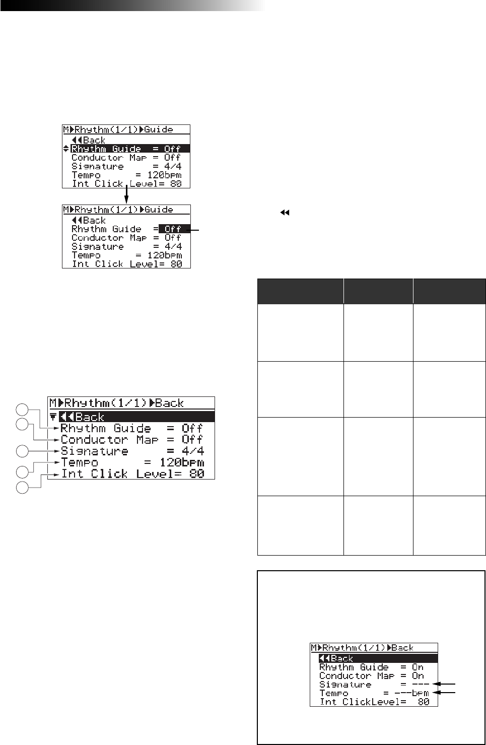
91
MR16 Owner’s Manual (Rhythm guide function)
Rhythm Guide: Off
Conductor Map: Off
Rhythm guide
No output
Bar/beat
indication
The "Signature"
and "Tempo"
item settings are
effective.
Rhythm Guide: Off
Conductor Map: On
No output The conductor
map is effective.
Rhythm Guide: On
Conductor Map: Off
Output:
The tempo and
time signature
setting on this
screen is effec-
tive.
The "Signature"
and "Tempo"
item settings are
effective.
Rhythm Guide: On
Conductor Map: On
Output:
The conductor
map setting is
effective.
The conductor
map is effective.
On/off conditions
1. Rhythm Guide: On/off selection of the rhythm guide
The setting you make here is reflected to the
[RHYTHM GUIDE] key (the key is lit when ON, while
it is unlit when OFF). Conversely, when you turn
on or off the rhythm guide using the
[RHYTHM GUIDE] key, the status is reflected to
this screen. See the table on the right for details.
2. Conductor Map: On/off selection of the conductor map
This item enables or disables the conductor map
(see "Conductor map" described later).
The default is "Off". See the table on the right for
details.
3. Signature: Time signature setting
The default is "4/4". You can select from among
1/4 through 5/4 and 1/8 through 8/8.
The setting here is effective from the beginning to
the end of the song when the "Conductor Map" item
is set to "Off" (i.e. the same time signature all
through the song). When the "Conductor Map" item
is set to "On", the setting here is ineffective.
See the table on the right for details.
You can make setting for each item similarly.
The rhythm guide setting screen has the following
items.
To exit the menu mode, press the [STOP] key, or se-
lect " Back" and press the [MENU/ENTER] knob re-
peatedly.
The table below shows how the "Rhythm Guide" and
"Conductor Map" item settings affect the conditions of
rhythm guide output and bar/beat indication.
3) Rotate the [MENU/ENTER] knob to select the
desired item, and press the [MENU/ENTER] knob.
The current setting of the selected item starts
flashing. On the screen examples below, the
"Rhythm Guide" item is highlighted (see the
upper screen) and the [MENU/ENTER] knob is
pressed (see the lower screen).
4) Rotate the [MENU/ENTER] knob to select the
desired option, and press the [MENU/ENTER]
knob.
The selected option (in the example above,
"On" or "Off") is confirmed and the display
returns to the previous screen.
4. Tempo: Tempo setting
The default is "120bpm". You can select between
30 and 250 bpm. The setting here is effective from
the beginning to the end of the song when the
"Conductor Map" item is set to "Off" (i.e. the same
tempo all through the song).
When the "Conductor Map" item is set to "On",the
setting here is ineffective. See the table on the
below for details.
5. Int ClickLevel: Internal click output level
The default is "80". You can set it between 0 and
99.
1
2
3
4
5
See the next page for details about how to set the
conductor map.
<Note>:
When “
Conductor Map
” is set to “
On
”, the
“
Signature
” and “
Tempo
” fields show “
- - -
” as be-
low. This indicates that the signature and tempo
values set on this screen are ineffective, while the
conductor map setting is effective.
Flashing
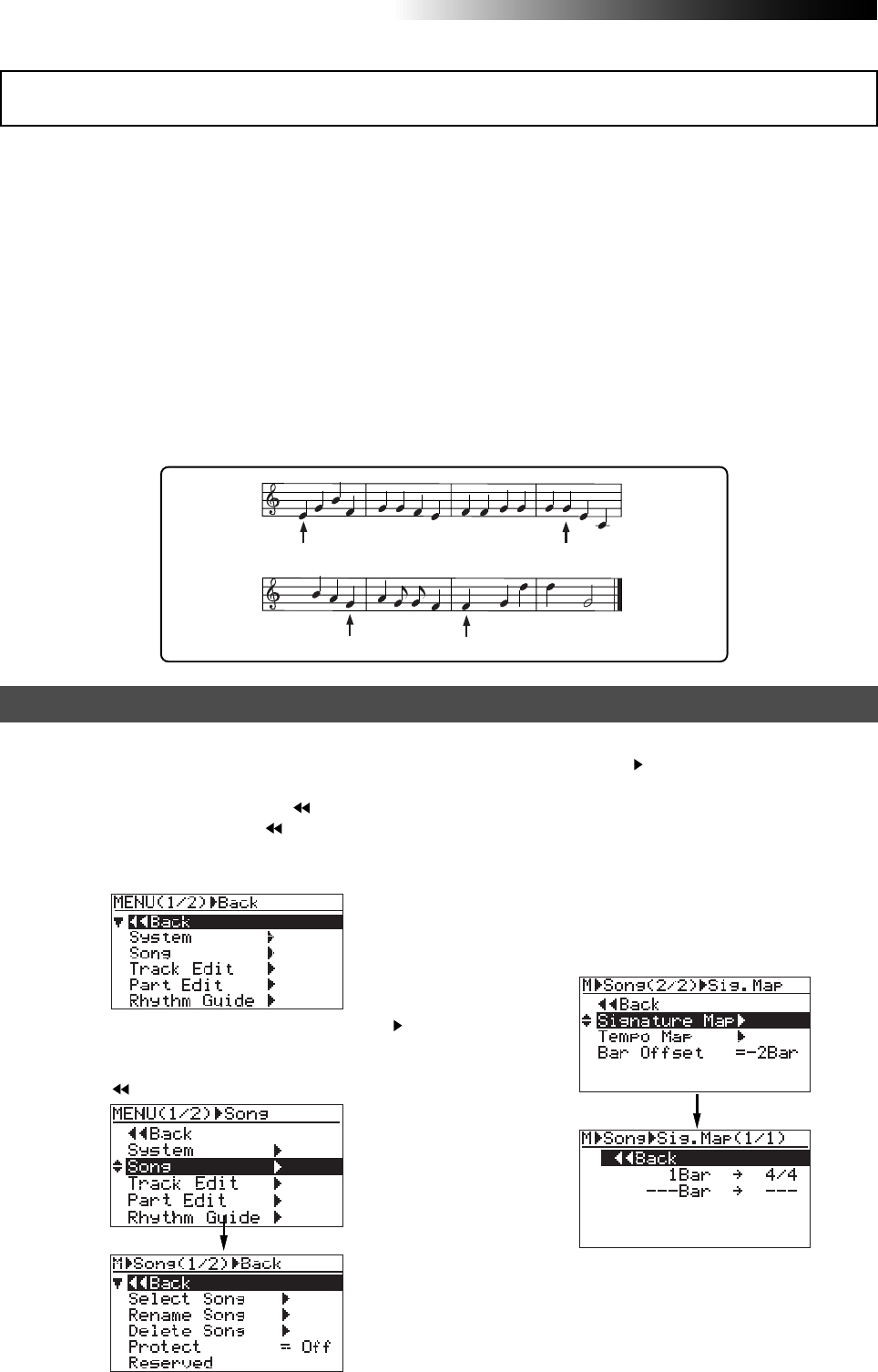
92
MR16 Owner’s Manual (Rhythm guide function)
2) Rotate the [MENU/ENTER] knob to select "Song ",
and press the [MENU/ENTER] knob.
The display now shows the song editing screen,
where " Back" is highlighted.
3) Rotate the [MENU/ENTER] knob to select
"Signature Map " on the second page, and press
the [MENU/ENTER] knob.
The display shows the signature map screen
on which the current time signature events are
listed. Each event specifies the bar number and
time signature. By default, "1Bar -> 4/4" and
"---Bar -> ---" are listed. In this condition, the
song is played in 4/4 from the beginning to
the end.
"---Bar -> ---" is used to create a new event.
The procedure example below shows how to
add the following events to the signature map.
1) While the recorder is stopped, press the
[MENU/ENTER] knob to enter the menu mode.
The display now shows the first page of the
menu selection screen, where " Back" is high
lighted initially (selecting " Back" returns to
the previous screen). You can also return to
the previous screen by pressing the [REWIND]
key.
Setting the signature map
The MR16 can output the rhythm guide click which follows the "conductor map" during record-
ing. It can also output MIDI clock and song position pointer which follows the "conductor map"
from the [MIDI OUT] connector.
The conductor map consists of the time signature map and tempo map. You can add "events" to
each map. Each event specifies the time signature or tempo, as well as the position from which
the specified time signature or tempo is effective. The time signature or tempo specified by each
event is effective until the next event in the map appears.
For example, if the time signature map has two events -- one sets "4/4" at the first bar 1, while the
other sets "2/4" at the third bar --, the song is played in 4/4 from bar 1 to 2, and played in 2/4
from bar 3 to the end.
For another example, if the tempo map has two events -- one sets "120" at the first bar 1/first beat
while the other sets "90" at bar 12/beat 2 --, the song is played at 120 bpm from bar 1 to bar 12/
beat 1, while it is played at 90 from bar 12/beat 2 to the end.
4
4
4
3
120 180
90 120
Creating the conductor map
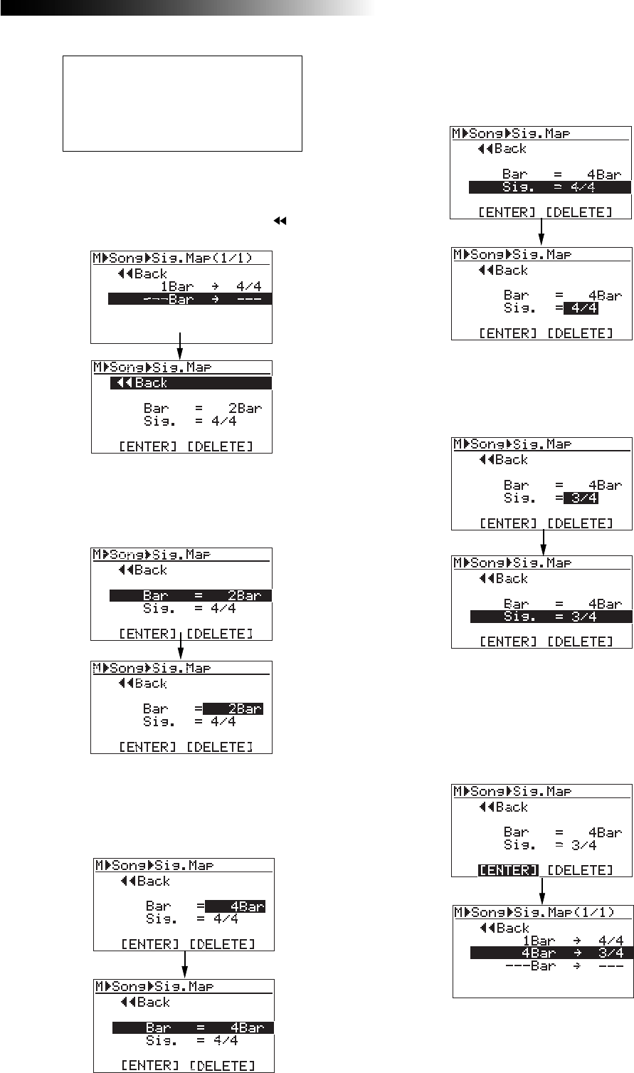
93
MR16 Owner’s Manual (Rhythm guide function)
4) Rotate the [MENU/ENTER] knob to select
"---Bar -> ---", and press the [MENU/ENTER] knob.
The display now shows the screen for setting
the new time signature event, where " Back"
is highlighted.
Bar 1 through bar 3 ------------------> 4/4
Bar 4 through bar 7 ------------------> 3/4
Bar 8 through bar 11 ----------------> 4/4
Bar 12 through bar 15 --------------> 5/8
Bar 16 through the last bar -------> 3/4
5) Rotate the [MENU/ENTER] knob to select
"Bar = 2Bar", and press the [MENU/ENTER] knob.
"2Bar" starts flashing and you can now set the
bar number.
6) Rotate the [MENU/ENTER] knob to enter the
desired bar number, and press the
[MENU/ENTER] knob.
In this procedure example, enter "4Bar".
The display returns to the previous screen.
7) Rotate the [MENU/ENTER] knob to select
"Sig. = 4/4", and press the [MENU/ENTER] knob.
"4/4" starts flashing and you can now set the
time signature.
8) Rotate the [MENU/ENTER] knob to select the
desired time signature, and press the
[MENU/ENTER] knob.
In this procedure example, enter "3/4".
The display returns to the previous screen.
9) Rotate the [MENU/ENTER] knob to select
"[ENTER]" at the bottom, and press the
[MENU/ENTER] knob.
The new time signature event is set and the
display shows the screen as below.
In this condition, the song is played in 4/4 from
bar 1 to bar 3 and in 3/4 from bar 4.
Repeat steps 5 through 9 until creating all nec-
essary events.
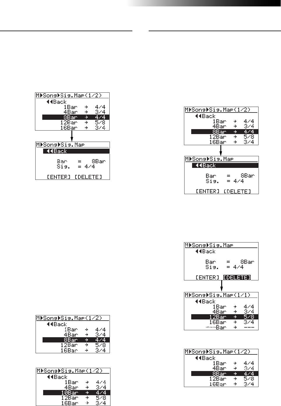
94
MR16 Owner’s Manual (Rhythm guide function)
• Deleting an unnecessary time signature event
You can delete an unnecessary time signature
event.
2) Rotate the [MENU/ENTER] knob to select
"[DELETE]" at the bottom, and press the
[MENU/ENTER] knob.
The event is immediately deleted and the
display returns to the signature map screen.
• Editing a time signature event
You can edit a time signature event.
2) To change the bar number, rotate the
[MENU/ENTER] knob to select "Bar = 8Bar", and
press the [MENU/ENTER] knob.
To change the time signature, rotate the
[MENU/ENTER] knob to select "Sig. = 4/4", and
press the [MENU/ENTER] knob.
As with the procedure described on the previous
page, you can now set the bar number or time
signature.
3) Rotate the [MENU/ENTER] knob to edit the value,
and press the [MENU/ENTER] knob.
In this procedure example, enter "10" for the
bar number.
4) Rotate the [MENU/ENTER] knob to select
"[ENTER]" at the bottom, and press the
[MENU/ENTER] knob.
The editing is confirmed and the display returns
to the signature map screen.
<Before editing>
<After editing>
To exit the menu mode, press the [STOP] key.
<Before deleting>
<After deleting>
To exit the menu mode, press the [STOP] key.
1) On the time signature map screen, rotate the
[MENU/ENTER] knob to select the event you want
to edit, and press the [MENU/ENTER] knob.
As with the description on the previous page, the
display now shows the screen for setting the event.
For example, let's select "8Bar -> 4/4".
1) On the time signature map screen, rotate the
[MENU/ENTER] knob to select the event you want
to delete, and press the [MENU/ENTER] knob.
As with the description on the previous page,
the display now shows the screen for setting
the event.
For example, let's select "8Bar -> 4/4".
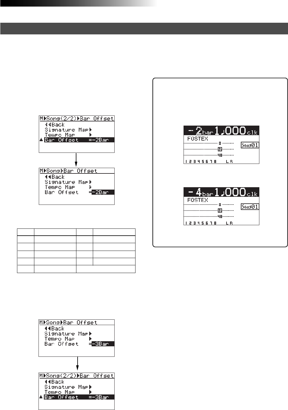
95
MR16 Owner’s Manual (Rhythm guide function)
By default, the bar/beat value at the beginning (ABS ZERO) of the song is set to "bar -2/beat 1".
This offset (the bar/beat value at ABS ZERO) is called "bar offset". You can change the default bar
offset to the desired value.
2) Rotate the [MENU/ENTER] knob to select the
desired offset value, and press the
[MENU/ENTER] knob.
The selected offset value is confirmed, while
the display returns to the previous screen.
Option
-8Bar
-7Bar
-6Bar
-5Bar
-4Bar
-3Bar
-2Bar
-1Bar
0Bar
ABS Zero= bar -8
ABS Zero= bar -7
ABS Zero = bar -6
ABS Zero= bar -5
ABS Zero= bar -4
ABS Zero= bar -3
ABS Zero= bar -2
ABS Zero= bar -1
ABS Zero= bar 1
Option
Meaning Meaning
The table below shows the available offset val-
ues.
To exit the menu mode, press the [STOP] key.
1) On the second page of the song editing menu
screen, highlight "Bar Offset" and press the
[MENU/ENTER] knob.
The current offset value (by default, "-2Bar")
starts flashing.
Editing the bar offset
You can see the bar offset value on the home
screen when the recorder is at the beginning
of the song (ABS 0).
The screen example below shows the home
screen when the bar offset is set to “-4 bars”.
The default home screen (bar offset = -2 bars).
The home screen when the
bar offset is set to “-4 bars”.
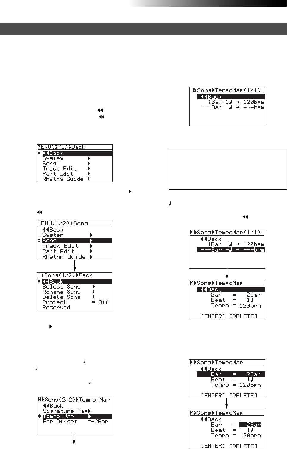
96
MR16 Owner’s Manual (Rhythm guide function)
Bar 1/beat 1 --------------------> 120 bpm
Bar 4/beat 2 --------------------> 180 bpm
Bar 8/beat 3 ----------------------> 90 bpm
Bar 12/beat 1 --------------------> 120 bpm
Bar 16/beat 4 --------------------> 250 bpm
After setting the time signature map, you have to create the tempo map by adding the necessary
tempo event(s). Like a time signature event, a tempo event specifies the tempo at the tempo
changing point. Each tempo specified by a tempo event is effective until the next event appears.
For example, you can set the tempo to 120 at the third beat in bar 4, and set to 90 at the second
beat in bar 12, etc.
Setting the tempo map
2) Rotate the [MENU/ENTER] knob to select "Song ",
and press the [MENU/ENTER] knob.
The display now shows the song editing screen,
where " Back" is highlighted.
1) While the recorder is stopped, press the
[MENU/ENTER] knob to enter the menu mode.
The display now shows the first page of the
menu selection screen, where " Back" is
highlighted initially (selecting " Back"
returns to the previous screen). You can also
return to the previous screen by pressing the
[REWIND] key.
3) Rotate the [MENU/ENTER] knob to select
"Tempo Map " on the second page, and press
the [MENU/ENTER] knob.
The display shows the tempo map screen on
which the current tempo events are listed.
Each event specifies the bar/beat position and
tempo. By default, "1Bar 1 -> 120 bpm" and
"---Bar - -> ---bpm" are listed. In this
condition, the song starts in 120 bpm and there
is no tempo change. "---Bar - -> ---bpm" is used
to create a new tempo event.
The procedure example below shows how to
add the following tempo events to the tempo
map.
4) Rotate the [MENU/ENTER] knob to select "---Bar -
-> ---bpm", and press the [MENU/ENTER] knob.
The display now shows the screen for setting
the new tempo event, where " Back" is
highlighted.
5) Rotate the [MENU/ENTER] knob to select
"Bar = 2Bar", and press the [MENU/ENTER] knob.
"2Bar" starts flashing and you can now set the
bar number. You can enter the bar number
between 1 and 999.
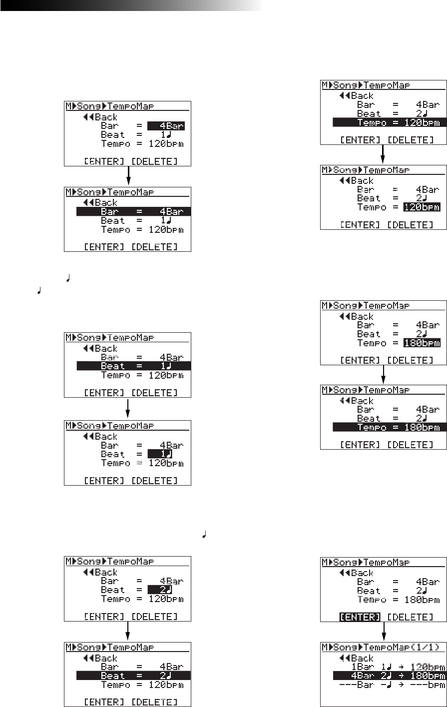
97
MR16 Owner’s Manual (Rhythm guide function)
7) Rotate the [MENU/ENTER] knob to select
"Beat = 1 ", and press the [MENU/ENTER] knob.
"1" starts flashing and you can now set the
beat number. You can enter the beat number
between 1 and 8.
8) Rotate the [MENU/ENTER] knob to enter the
desired beat number, and press the [MENU/ENTER]
knob.
In this procedure example, let's enter "2".
The display returns to the previous screen.
11) Rotate the [MENU/ENTER] knob to select "[ENTER]"
at the bottom, and press the [MENU/ENTER] knob.
The new tempo event is set and the display
shows the screen as below. In this condition,
the song is played in 120 bpm from the
beginning to bar 4/beat 1 and in 180 from bar
4/beat 2 to the end.
Repeat steps 4 through 11 until creating all
necessary tempo events.
"120bpm" starts flashing and you can now set
the tempo. You can enter the tempo between
30 and 250.
10) Rotate the [MENU/ENTER] knob to enter the desired
tempo, and press the [MENU/ENTER] knob.
In this procedure example, enter "180bpm".
The display returns to the previous screen.
6) Rotate the [MENU/ENTER] knob to enter the
desired bar number, and press the
[MENU/ENTER] knob.
In this procedure example, enter "4Bar".
The display returns to the previous screen.
9) Rotate the [MENU/ENTER] knob to select
"Tempo = 120bpm", and press the [MENU/ENTER]
knob.
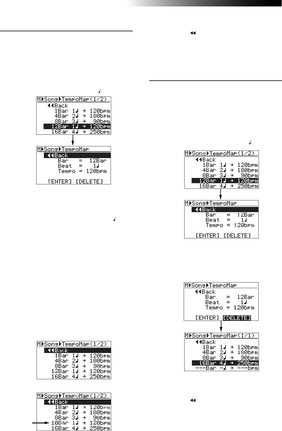
98
MR16 Owner’s Manual (Rhythm guide function)
• Deleting an unnecessary tempo event
You can delete an unnecessary tempo event.
2) Rotate the [MENU/ENTER] knob to select
"[DELETE]" at the bottom, and press the
[MENU/ENTER] knob.
The event is immediately deleted and the
display returns to the tempo map screen.
• Editing a tempo event
You can edit a tempo event.
2) To change the bar number, rotate the
[MENU/ENTER] knob to select "Bar = 12Bar", and
press the [MENU/ENTER] knob.
To change the beat number, rotate the
[MENU/ENTER] knob to select "Beat = 1 ", and
press the [MENU/ENTER] knob.
To change the tempo, rotate the [MENU/ENTER]
knob to select "Tempo = 120bpm", and press the
[MENU/ENTER] knob.
As with the procedure described on the previous
page, you can now set the bar number, beat
number or tempo.
3) Rotate the [MENU/ENTER] knob to edit the value,
and press the [MENU/ENTER] knob.
In this procedure example, let's enter "10" for
the bar number.
4) Rotate the [MENU/ENTER] knob to select "[ENTER]"
at the bottom, and press the [MENU/ENTER] knob.
The editing is confirmed and the display returns
to the tempo map screen.
<Before editing>
<After editing>
<After deleting>
To exit the menu mode, press the [STOP] key,
or select " Back" and press the [MENU/ENTER]
knob repeatedly.
1) On the tempo map screen, rotate the
[MENU/ENTER] knob to select the event you want
to edit, and press the [MENU/ENTER] knob.
As with the description on the previous page,
the display now shows the screen for setting
the event.
For example, let's select "12Bar 1 -> 120bpm".
1) On the tempo map screen, rotate the
[MENU/ENTER] knob to select the event you want
to delete, and press the [MENU/ENTER] knob.
As with the description on the previous page,
the display now shows the screen for setting
the event.
For example, let's select "12Bar 1 ->120bpm".
To exit the menu mode, press the [STOP] key,
or select " Back" and press the [MENU/ENTER]
knob repeatedly.

99
MR16 Owner’s Manual (MIDI synchronization)
MIDI synchronization
By connecting the external MIDI devices (such as a sequencer, sound
module, computer, etc.) via the [MIDI OUT] connector of the MR16, you
can make powerful recording.
For example, by synchronizing a sequencer with the MR16 during play-
back, you can mix down signals (such as a vocal, guitar, etc.) recorded on
the MR16 tracks and audio from a sound module.
You can synchronize MIDI with the MR16 by connecting a MIDI device to
the [MIDI OUT] connector on the MR16 and sending out MTC (MIDI time
code) or MIDI clock (with Song Position Pointer) from the MR16.
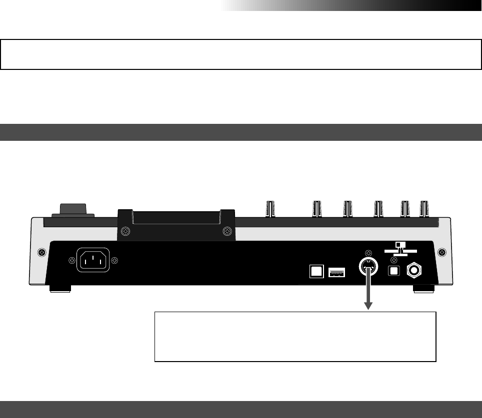
100
MR16 Owner’s Manual (MIDI synchronization)
The following describes how to synchronize a sequencer to the MR16 which supports MTC (MIDI
Time code).
Connect the [MIDI OUT] connector of the MR16 to the [MIDI IN] connector of an external MIDI se-
quencer using a MIDI cable. (Note that no MIDI cable is supplied with the MR16. Use a commercially
available MIDI cable.)
1) Set the "Midi Sync Out" item in the "System" menu of the menu mode to "MTC" and the "MTC Frame Rate"
to an appropriate frame rate.
See "MIDI sync/MTC frame rate settings" described below for details.
2) Enable the external MIDI sequencer to synchronize to MTC.
See the operation manual of the sequencer for details.
3) Press the [PLAY] key of the MR16 to start playback.
The sequencer automatically starts playback while synchronizing to the MR16.
USB USB HOST MIDI OUT DIGITAL OUT FOOT SW
INPUT A SEL
GTR CLEAN MIC/LINE
GTR DIST
MIDI sequencer, etc.
Connection
Settings of the MR16 & MIDI sequencer
Synchronization using MTC
MIDI IN
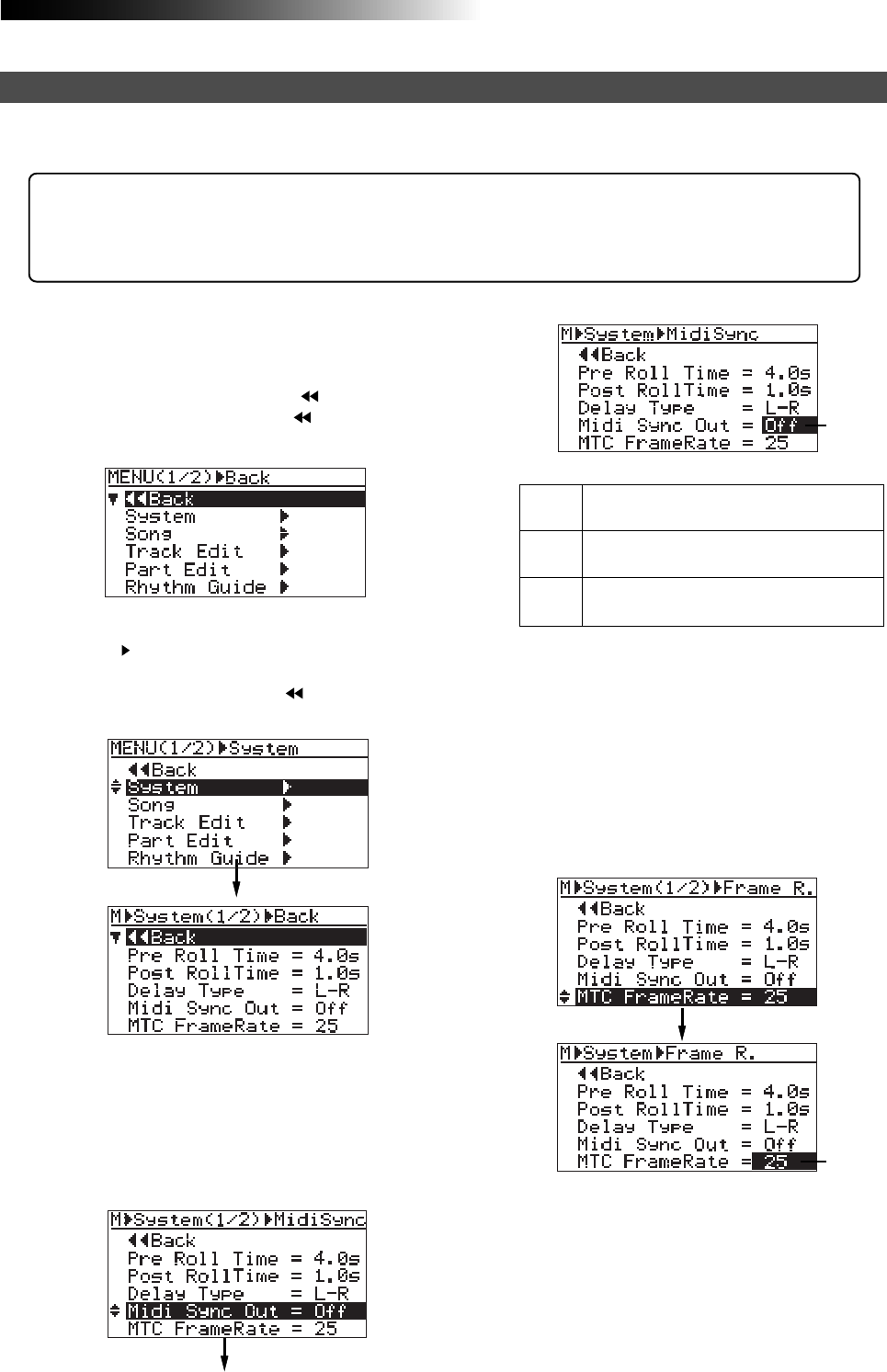
101
MR16 Owner’s Manual (MIDI synchronization)
6) Rotate the [MENU/ENTER] knob to select the
desired frame rate, and press the [MENU/ENTER]
knob.
The selected frame rate is now effective, while
"MTC FrameRate=**" is highlighted on the screen.
7) Press the [STOP] key to exit the menu mode.
5) Rotate the [MENU/ENTER] knob to select
"MTC FrameRate=**", and press the [MENU/ENTER]
knob.
The current option (the default is "25") flashes.
You can now select the desired frame rate (the
options are "24", "25", "30nd" and "30df").
The current option (the default is "Off") flashes.
You can now select the desired option (the
available options are Off, CLK and MTC).
Off
CLK
MTC
No signal is output from the [MIDI OUT]
connector. This is the default.
MIDI clock with Song Position Pointer is
output from the [MIDI OUT] connector.
MIDI time code is output from the [MIDI
OUT] connector.
4) Rotate the [MENU/ENTER] knob to select "MTC",
and press the [MENU/ENTER] knob.
"Midi Sync Out" is now set to "MTC", while
"Midi Sync Out" is highlighted on the screen.
While the MR16 is stopped, you can set the reference of MIDI synchronization to "MTC" and the MTC
frame rate appropriately to match the sequencer.
2) Rotate the [MENU/ENTER] knob to select
"System ", and press the [MENU/ENTER] knob.
The display now shows the first page of the
system menu screen, where " Back" is
highlighted initially.
<MTC start time>:
The MTC from the MR16 has one hour offset to the ABS time (the offset value is fixed).
Therefore, when you start the MR16 from the beginning of a song (ABS ZERO), the MTC starts
from "01h 00m 00s 00f".
1) While the recorder is stopped, press the
[MENU/ENTER] knob to enter the menu mode.
The display now shows the first page of the
menu selection screen, where " Back" is
highlighted initially (selecting " Back" returns
to the previous screen).
MIDI sync/MTC frame rate settings
3) Rotate the [MENU/ENTER] knob to select
"Midi Sync Out=***", and press the [MENU/ENTER]
knob.
Flashing
Flashing
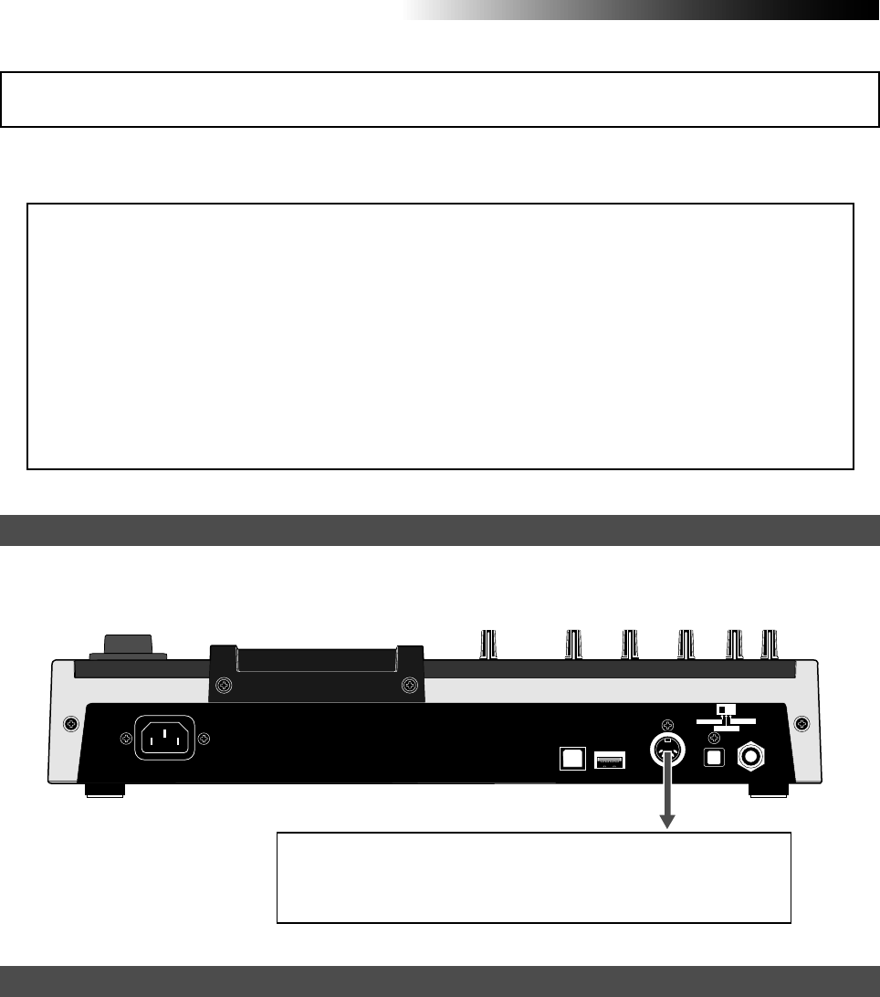
102
MR16 Owner’s Manual (MIDI synchronization)
The following describes how to synchronize a sequencer to the MR16 using MIDI clock.
Use this method if the sequencer does not support MTC (MIDI Time code).
<Notes>
• To synchronize a sequencer to the MR16 using MIDI clock, you have to make the signature/
tempo map in the MR16.
The MIDI clock is output based on the signature/tempo map in the MR16.
When you record MIDI sounds, synchronize the sequencer to the MIDI clock fed from the
MR16.
• Generally, a sequencer supporting MIDI song position pointer as well as MIDI clock can
synchronize to the MR16 when you start playback of the MR16 from the middle of a song.
It locates the current song position and chases the MR16.
However, note that some sequencer may not synchronize to the MR16.
1) Set the "Midi Sync Out" item in the "System" menu of the menu mode to "Clk".
See "MIDI sync/MTC frame rate settings" described above about how to set.
2) Create the signature/tempo map by setting "Signature Map" and "Tempo Map" items in the "Song"
menu of the menu mode appropriately.
See "Using the rhythm guide function" on page 90 for details about how to set these items.
3) Enable the external MIDI sequencer to synchronize to MIDI clock.
See the operation manual of the sequencer for details.
4) Press the [PLAY] key of the MR16 to start playback.
The sequencer also starts playback in sync with the MR16.
Connection
As with the connection for MTC synchronization, connect the [MIDI OUT] connector of the MR16 to the
[MIDI IN] connector of an external MIDI sequencer using a MIDI cable.
Settings of the MR16 & MIDI sequencer
Synchronization using MIDI clock
USB USB HOST MIDI OUT DIGITAL OUT FOOT SW
INPUT A SEL
GTR CLEAN MIC/LINE
GTR DIST
MIDI sequencer, etc.
MIDI IN

103
MR16 Owner’s Manual (Data export to a personal computer)
Data export to a personal computer
<Notes on USB connection with Mac OS>
When making USB connection with a Macintosh computer, note that only Mac OS X
or higher is supported. Do not connect to a Macintosh computer with the earlier
version. The song data on the MR16 may be damaged.
This chapter describes how to export song data bounced to tracks 15/16
of the current or new song to a personal computer.
To export song data to a personal computer, you must convert it to a
stereo WAV file.
You can export the converted (WAV) file to the personal computer via
the [USB] port and create an audio CD using a CD burning function on
the personal computer.
Note that you can also create an audio CD by connecting the external
CD-R/RW drive to the [USB HOST] port of the unit, or using the internal
CD-R/RW drive if it is provided to your MR16 (see the "How to use the
CD-R/RW drive" supplementary manual).
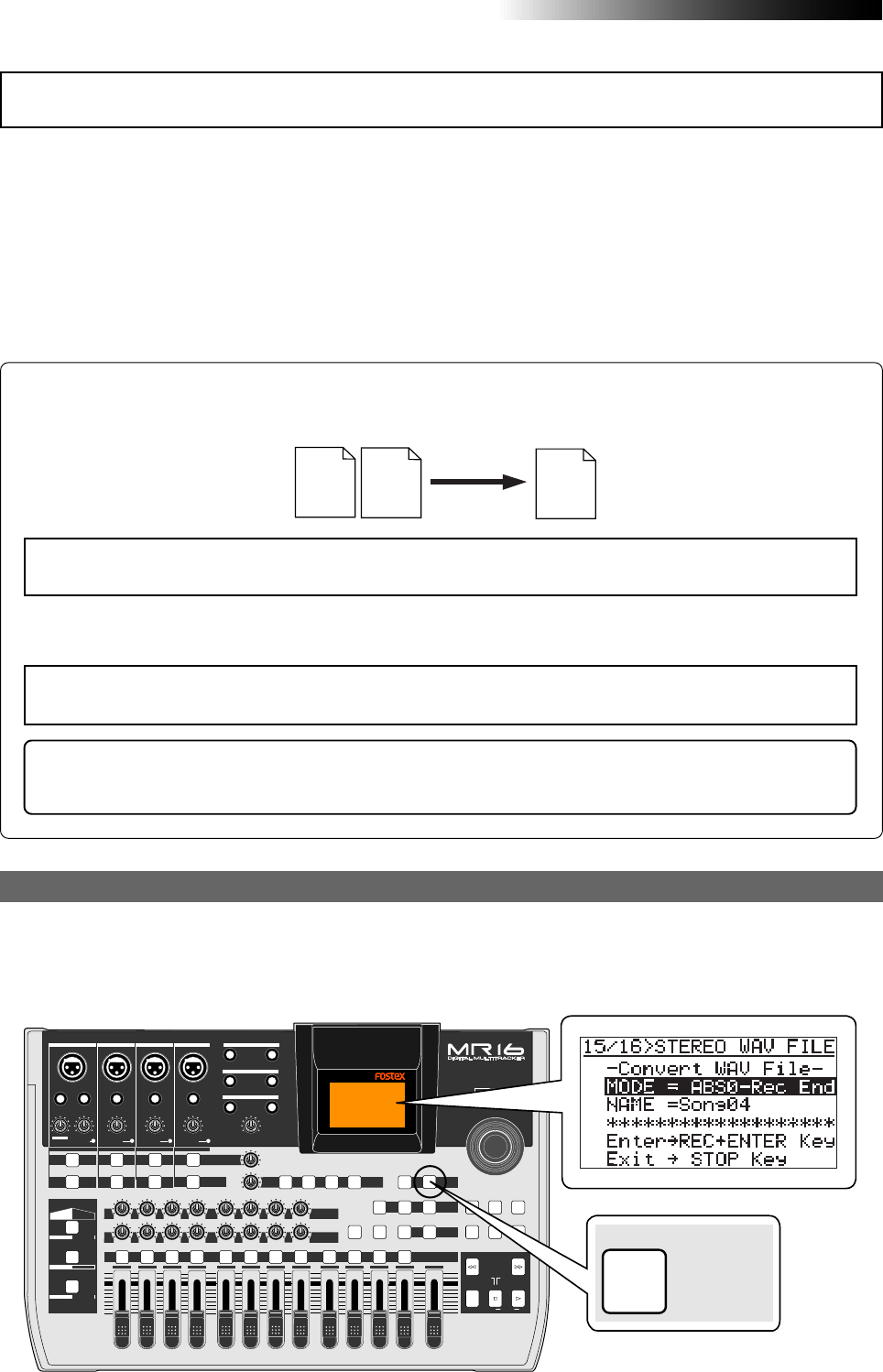
104
MR16 Owner’s Manual (Data export to a personal computer)
You can enable the WAV file conversion function by pressing the [15/16 > STEREO WAV FILE] key.
You can disable the WAV file conversion function by pressing the [STOP] key. When the WAV file
conversion function is active, the display shows the screen as below.
Track 15
(L ch) Track 16
(R ch) Stereo
(L, R)
Two mono WAV files recorded on tracks 15/16 are converted to a stereo WAV file as shown below.
(Note that only files recorded on tracks 15/16 can be converted to a stereo WAV file.)
You can convert all track data (from ABS ZERO to REC END) or data of a specified part (between the
LOCATE A and LOCATE B points).
<Note>:
If you want to convert a part of track data, you have to set the LOCATE A and LOCATE B points
in advance.
<Note>:
If you are going to make conversion when no WAV data exists on tracks 15/16, the error
message ("Track 15/16 Empty!") appears and the operation is canceled.
Enabling the file conversion
WAV file conversion
<Hint>: You can play back a converted stereo WAV file for checking, as well as set CUE points for
dividing file data into individual CD tracks before writing it to a CD-R/RW disc.
See the supplementary manual “How to use the CD-R/RW drive” for details.
PEAK
GUITAR
MIN
DISTORTION
MAX LINE MIC
TRIM
INSERT/GUITAR
UNBAL
BALBALBALBAL
INPUT A INPUT B INPUT C INPUT D
VOLUME
MIN MAX
PEAK
LINE
TRIM
MIC
UNBAL
POWER
UNBAL
MIC
TRIM
LINE
PEAK
UNBAL
MIC
TRIM
LINE
PEAK
MAX
MIN
1
R
L
100
SIMULATION SIMULATION
AMP
MIC
010
LR
010
LR
23
RL
100
4 8
010
LR
7
6
RL
100
RL
100
010
LR
5
MAX
MIN
MASTER
REC SELECT
RECORD STOP PLAY
REWIND F FWD
UNDO/REDO
STORE
LOCATE REC END
LOCATE ABS ZERO
A-B PLAY
BOUNCE
MASTERING
BRIGHT
15/16 > STEREO WAV FILE
NATURAL
POWERFUL
B / OUTA / INPLAY MODEAUTO PUNCH
LOCATE
EFFECT
DELAYPLATEHALLROOM BOUNCE MODE
CONTRAST
TIMEBASE SELECT
RHYTHM GUIDE DIRECT LOCATE
EFFECT SEND
PAN
INPUT EQ
TO STEREO BUSS LEVEL
9/10 11/12 13/14 15/16
ABC1 DEF2 GHI3 JKL4 MNO5 YZ9PQR6 +-_0STU7 VWX8 DELETE
MENU / ENTER
MIN MAX
MIN MAX
REVERB / DELAY TIME
LSTEREO OUT R
1AUX OUT 2
1PHONES 2
DYNAMIC BRIT STACK
CONDENSER US METAL
TUBE 60'S COMBO
INPUT A INPUT B INPUT C INPUT D
15/16 > STEREO WAV FILE
The following describes how to convert track data (bounced to track 15/16 of the same song or
the new song, or recorded to tracks 15/16 in stereo) to a stereo WAV file. You can export a
converted WAV file to your personal computer and burn it to an audio CD using the CD-R
function of the personal computer. You can also burn track data to an audio CD by connecting
the external CD-R/RW drive to the [USB HOST] port of the unit, or using the internal CD-R/RW
drive if it is provided to your MR16 (see the "How to use the CD-R/RW drive" supplementary
manual). For details about how to export a converted WAV file to your personal computer, see
page 107 below. For details about how to burn track data to an audio CD using the external or
internal CD-R/RW drive, see the "How to use the CD-R/RW drive" supplementary manual.
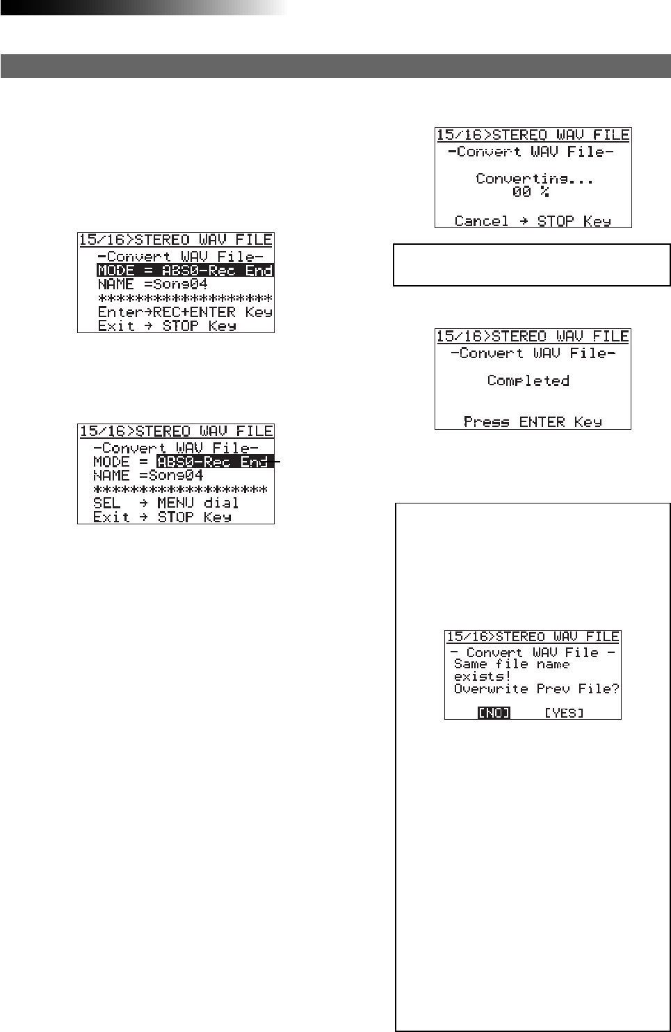
105
MR16 Owner’s Manual (Data export to a personal computer)
1) While the recorder is stopped, press the
[15/16 > STEREO WAV FILE] key to enable the
file conversion function.
The display shows the "15/16 > STEREO WAV
FILE" screen, on which "ABS0-Rec End" is
highlighted.
The following assumes that the song whose track data you want to convert is loaded.
To convert all track data, select "ABS0-Rec End".
To convert a specified range, select "LOCATE A
- LOCATE B".
2) Press the [MENU/ENTER] knob.
"ABS0-Rec End" starts flashing, and you can
now select the conversion range between
"ABS0-Rec End" and "LOCATE A - LOCATE B".
3) Rotate the [MENU/ENTER] knob to select the
conversion range and press the [MENU/ENTER]
knob.
The selection is confirmed and the display
returns to the previous screen.
Procedure of file conversion
"NAME = *********" shows the name for the con-
verted file, and you can enter a desired name.
Initially, it shows the name of the source file,
therefore, if you do not change the name, the
same file name is given.
The following assumes that the file name is not
changed. For details about how to edit a name,
see "Editing a file name" on the next page.
When you convert data in the same song more
than once, you have to give a different name
for each converted file. See the <Note> on the
next page.
Flashing 5) Press the [MENU/ENTER] knob.
The MR16 quits the conversion function and
the display returns to the home screen.
<Note>:
If you convert data with the same
name as previously converted data, the fol-
lowing screen appears on the display.
This screen warns you that the WAV file with
the same name already exists and asks you
to carry out the conversion by overwriting
the existing file or cancel the conversion.
If you carry out the conversion by overwrit-
ing the existing file, rotate the [
MENU/EN-
TER
] knob to move the cursor to "
[YES]
",
and press the [
MENU/ENTER
] knob.
If you do not want to overwrite the existing
file, rotate the [
MENU/ENTER
] knob to move
the cursor to "
[NO]
", then press the [
MENU/
ENTER
] knob. The display returns to show
the screen for editing the file name, so you
can enter a different file name and then
carry out the conversion.
If you want to cancel the conversion when
the screen above is shown, rotate the [
MENU/
ENTER
] knob to move the cursor to "
[NO]
"
and press the [
MENU/ENTER
] knob to show
the screen for editing the file name, and then
press the [
STOP
] key to quit the conversion
function.
When the conversion is completed, the display
shows "Completed".
<Note>:
If you cancel the conversion in the
middle, no file (incomplete file) is created.
4) Press the [MENU/ENTER] knob while holding
down the [RECORD] key.
The file conversion starts and the percent
number on the screen counts up as the
conversion progresses.
To cancel the conversion in the middle, press
the [STOP] key.
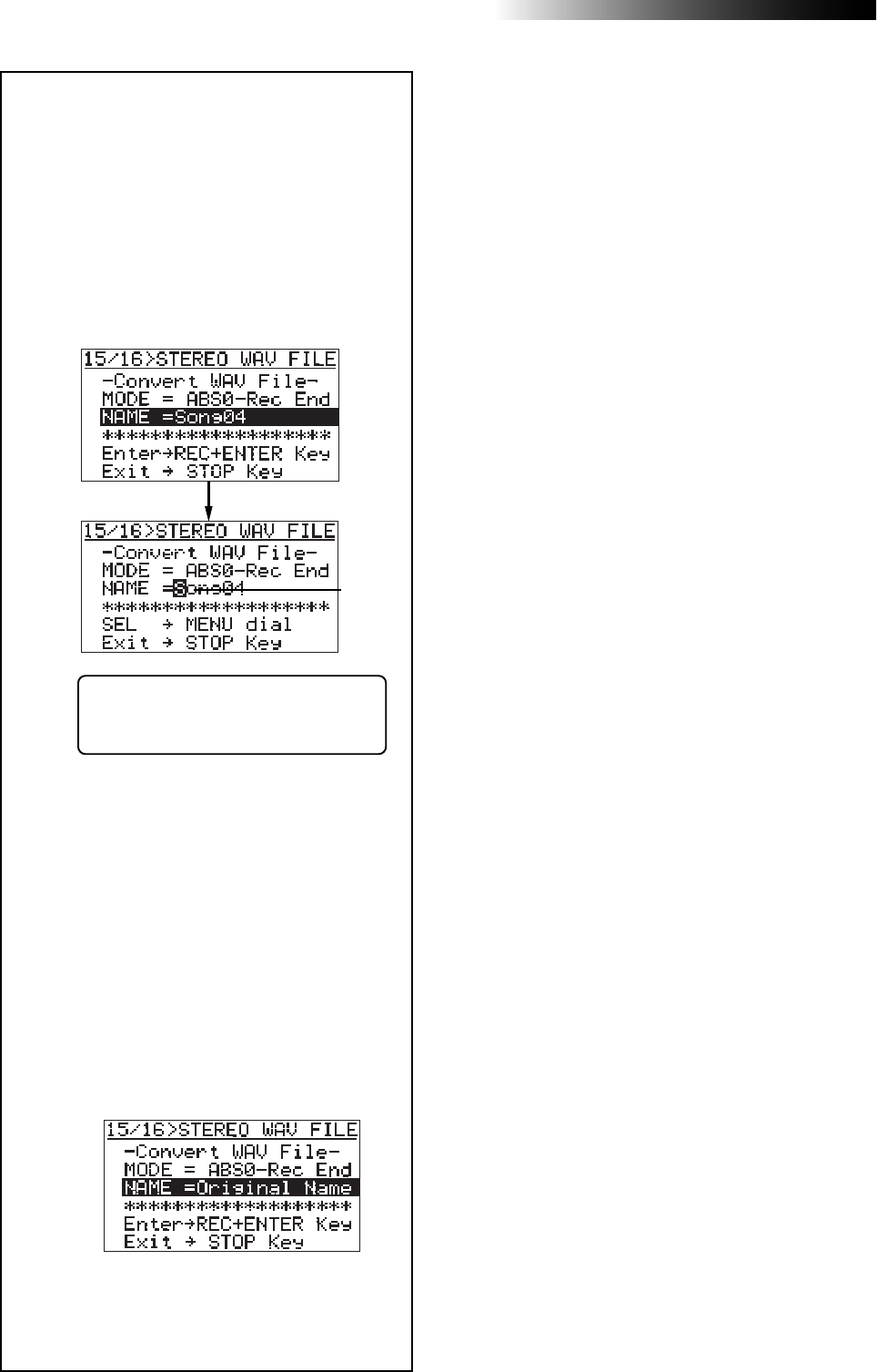
106
MR16 Owner’s Manual (Data export to a personal computer)
<Editing a file name>
You can edit a file name by the follow-
ing procedure.
2) Enter a new name using the character
entry keys.
Pressing a different character entry key
automatically moves the cursor right.
If two successive characters are assigned
to the same character entry key, rotate
the [MENU/ENTER] knob after selecting
the first character to move the cursor
right.
3) After entering a new name, press the
[MENU/ENTER] knob.
The entered name is set and the display
returns to the previous screen.
The screen example below shows the
name is set to "Original Name".
While the rightmost character is flash-
ing, pressing the [DELETE] key repeat-
edly deletes the current file name.
Flashing
1) After selecting the range of track data to
be converted, rotate the [MENU/ENTER]
knob to move the cursor to "NAME" and
press the [MENU/ENTER] knob.
The rightmost character of the file name
starts flashing. You can now start
editing.
Then, by pressing the [MENU/ENTER] knob
while holding down the [RECORD] key to carry
out the WAV file conversion.
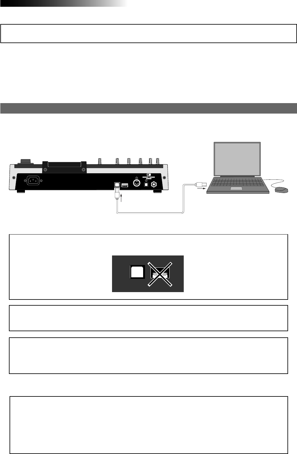
107
MR16 Owner’s Manual (Data export to a personal computer)
Connection to a personal computer
Connect the [USB] port of the MR16 to the USB port of a personal computer using a USB cable, as
shown above. (A USB cable is not supplied with the MR16.)
Windows Me/2000/XP machine supporting
USB connection
USB cable
<Note>:
Only Windows Me, 2000 and XP computers, as well as Macintosh computers with OS X or
higher, can be used with the MR16.
Other computers cannot be used. Check your computer before making connection.
<Notes on USB connection with Mac OS>
When making USB connection with a Macintosh computer, note that only Mac OS X or higher is
supported. Do not connect to a Macintosh computer with the earlier version. The song data on the
MR16 may be damaged.
USB USB HOST MIDI OUT DIGITAL OUT FOOT SW
INPUT A SEL
GTR CLEAN MIC/LINE
GTR DIST
PC
USB USB HOST
<Caution>:
Use the [
USB
] port for connection to a personal computer. Do not connect the [
USB HOST
]
port to a personal computer.
Exporting data to a personal computer
* All company names and model names mentioned in this manual are trademarks or registered trade-
marks of their respective holders.
The unit is equipped with the [USB] port for directly connecting to a personal computer using a
USB cable. Via USB connection, you can export audio data converted to a stereo WAV file to a
personal computer. The exported file can be played back or edited on the personal computer, or
can be burned to an original audio CD using the software application (WAV Manager) provided
by Fostex. You can also use the export function for data backup purpose.
<About downloading WAV Manager>
You can download WAV Manager, a software application for multitrack recording provided
by Fostex, from Fostex web site (http://www.fostex.com). Before importing a WAV file from
the MR16 or creating an audio CD, download WAV Manager and install it to your personal
computer. For details about how to use WAV Manager, see the manual supplied with the
downloaded file.
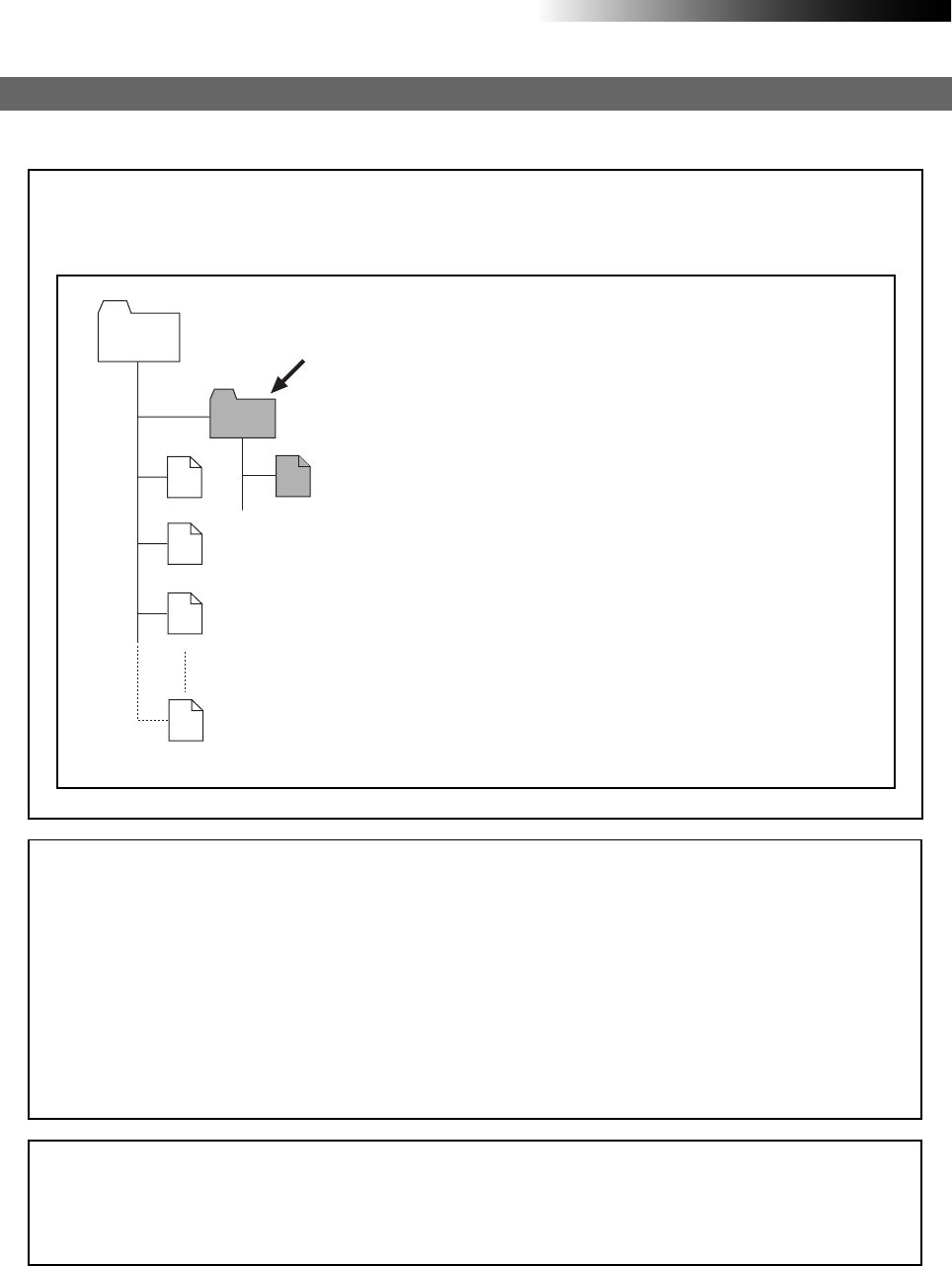
108
MR16 Owner’s Manual (Data export to a personal computer)
<Important note>
Converted stereo WAV files are located in the "2 MIX"
folder in the Song folder, as shown below. So you can
export only a stereo WAV file in the "2 MIX" folder (in-
dicated by an arrow).
Note that, if you export a WAV file which is located in a
folder other than the "2 MIX" folder, the MR16 may mal-
function.
Exporting a WAV file to a personal computer
The following describes the procedure for exporting a WAV file to a Windows ME computer.
#####001.wav
Song
#####002.wav
#####003.wav
#####008.wav
2 MIX
*********.wav
<Note on backup>
When exporting song data on the hard disk to a personal computer for backup, always export
the whole song folder. You cannot export individual track data.
See “
Archiving a song
” on page 111 for details about song data backup.
<Note>:
You can export only a stereo WAV file which is converted from a pair of mono WAV
files on tracks 15/16, as described earlier in "WAV file conversion". A mono WAV file or undo
file cannot be exported to a personal computer.
<Disk protection>
By default, the “
disk protect
” function which is effective in the USB mode is set to “
On
”.
In this condition, the MR16 can export data to a personal computer but cannot import data
from a computer. This is for protecting the MR16 internal hard disk from importing a file
from a computer inappropriately and destroying the MR16 song data.
You can enable or disable this function, however, we recommend using the MR16 by setting
it to “
On
”.
If you use the MR16 by setting the “disk protect” function to “
Off
”, read “
Archiving a song
” on
page 111 before using. See page 110 for details about how to make the “
disk protection
”
setting.
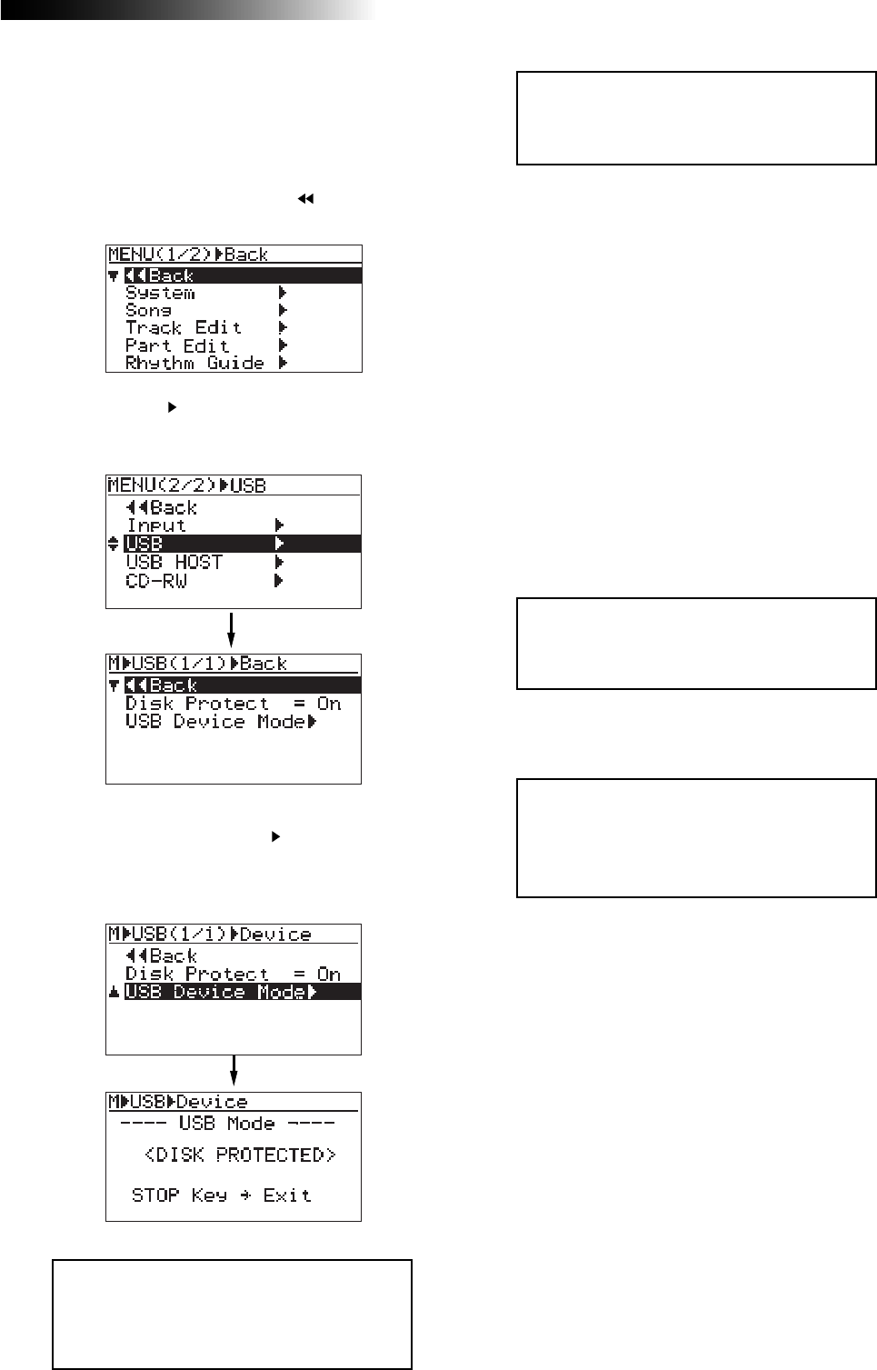
109
MR16 Owner’s Manual (Data export to a personal computer)
3) Highlight "USB " by rotating the [MENU/ENTER]
knob, then press the [MENU/ENTER] knob.
The display shows the USB menu screen.
1) Turn on the power of the personal computer and
the MR16.
2) Press the [MENU/ENTER] knob to enter the menu
mode.
The display now shows the first page of the
menu selection screen, where " Back" is
highlighted initially.
5) Connect the MR16 to a personal computer using
a USB cable.
6) Open "My computer" on the computer screen.
You see the "Removable disk" drive added on
the computer. The first time you connect the
MR16, the device driver is installed
automatically.
7) Open the added Removable disk drive, and
select the stereo WAV file in the desired song
folder, then copy to the computer.
When you open the added Removable disk
drive, the contents of the MR16 hard disk are
shown, in which you can see all the song
folders.
Open the "2 MIX" folder in the desired song
folder, and select the stereo WAV file, then copy
it to the computer.
<Note>:
By default, the disk protect func-
tion is enabled. In this condition, when the
MR16 enters the USB mode, “
<DISK PRO-
TECTED>
” is shown in the USB screen, as
above.
<Note>:
After copying a WAV file in the folder
to a computer, the original file remains. How-
ever, if you execute "
move to another folder
",
the original file on the disk is lost.
<Note>:
To disconnect the MR16 from the
personal computer after completing the data
export, make sure that the [
RECORD
] key
indicator is not lit, and follow the procedure
for hardware disconnection of Windows.
8) When the data export completes, disconnect the
MR16 from the personal computer.
4) Rotate the [MENU/ENTER] knob to move the
cursor to “USB Device Mode ”, and press the
[MENU/ENTER] knob.
The MR16 enters the USB mode and the
display shows the screen as below.
9) Press the [STOP] key to exit the menu mode.
<Note>:
While the MR16 is in the USB mode,
all keys except the [
STOP
] key are ineffec-
tive. Pressing the [
STOP
] key exits the USB
mode.
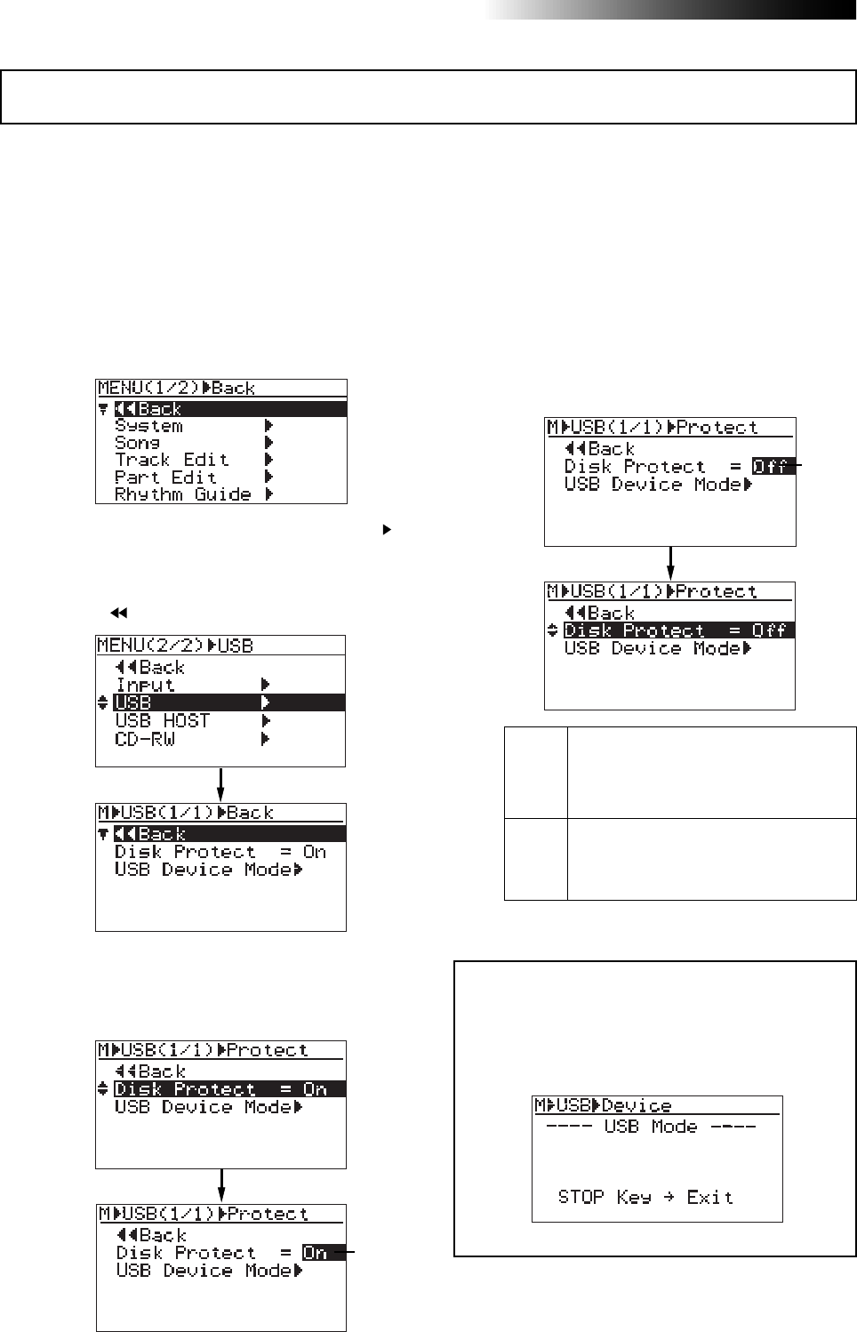
110
MR16 Owner’s Manual (Data export to a personal computer)
The MR16 internal hard disk is protected by default.
The protection is effective only in the USB mode in which the MR16 is used with a personal
computer. You can make the hard disk “read only” (protected) or “read/write enabled” (unprotected).
The default is “read only”. As mentioned earlier in “<Disk protection>” on page 108, if you transfer
song data from a computer to the MR16 improperly, the data may be damaged. To avoid such an
accident, we recommended enabling hard disk protection. To disabling the disk protection,
follow the procedure below.
1) While the recorder is stopped, press the
[MENU/ENTER] knob to enter the menu mode.
2) Rotate the [MENU/ENTER] knob to select “USB ”
on the second page, and press the
[MENU/ENTER] knob.
The display now shows the USB menu screen,
where “ Back” is highlighted.
3) Rotate the [MENU/ENTER] knob to highlight “Disk
Protect=**”, and press the [MENU/ENTER] knob.
The current setting (the default is “On”)
flashes.
4) Rotate the [MENU/ENTER] knob to select “Off”,
and press the [MENU/ENTER] knob.
The selection is confirmed and the display
returns to the previous screen.
5) Press the [STOP] key to exit the menu mode.
Off
The disk is “read/write enabled”
(unprotected). You can transfer data
between the MR16 and a computer in both
ways.
On The disk is “read only” (protected).
You can transfer data only from the MR16
to a computer (default setting).
<Note>:
When you enter the USB mode while the
disk protection is disabled, the screen as below is
shown. In this condition, the hard disk is “
read/
write enabled
” and you can bi-directionally trans-
fer song data between a computer and the MR16.
Protecting the hard disk
Flashing
Flashing
111
MR16 Owner’s Manual (Data export to a personal computer)
You can archive song data recorded by the MR16 by using either of the following methods.
(1) Using the WAV Manager supplied by Fostex
The WAV Manager converts each track data to a single mono file. Data is compressed so you
can save the file in small size to a personal computer. This method is useful for exporting
data to a PC software application for multitrack recording.
For details about how to use the WAV Manager, see the owner's manual supplied with the
WAV Manager. You can download the WAV Manager from Fostex web site (http://
www.fostex.com).
(2) Using drag & drop technique
You can copy a song folder using drag & drop technique. This method allows saving all data
in the folder (including the history data, etc.).
<Note>:
When drag & drop the folder on your personal computer, use the "copy"
function. If you use the "move" function, not only the song on the MR16 is deleted but
also other songs on the MR16 may be destroyed. We recommend to enable the disk
protection (the default is "enabled") when executing data copy.
Using this method, you can also copy the hidden folder which includes hidden files
"deleted" by the MR16 song management operation. Copied hidden files can be used
as a normal song files by turning off the hidden attribute by the computer.
<Note>:
If you cannot see the hidden folder, consult the manual of your personal
computer.
• Importing data from a personal computer
When importing data from a personal computer to the MR16, there is the danger that
the MR16 file system may be destroyed. Especially, deleting or adding files many times
may cause the fragmentation of FAT32, resulting in sound jump caused by perfor-
mance deterioration. Therefore, before loading data from a personal computer to the
MR16, save all necessary folders to the personal computer and format the MR16 hard
disk.
1) Format the MR16 internal hard disk (see page 140).
2) Disable the disk protection (see page 110).
3) Connect the MR16 to a personal computer via USB (see page 109).
4) Copy the desired song folder on the personal computer to the root folder of the
MR16 hard disk.
<Note>:
Do not use "move" operation, as with saving data to a computer.
Archiving a song
• Exporting data to a personal computer
1) Connect the MR16 to a personal computer via USB, and open the root folder.
You can copy each song folder in the root folder to the personal computer.
2) Copy a desired song folder to the personal computer using drag & drop technique.
3) After making copy, exit the USB mode.

112
MR16 Owner’s Manual (Data export to a personal computer)
(3) Copy data to a CD-R/RW disc using the internal CD-R/RW drive.
As with (1), each track data is converted to a single mono WAV file.
The data is compressed to a small size and saved to a CD-R/RW disc. See the supplemen-
tary manual "How to use the CD-R/RW drive" for details.
5) Repeat step 4) as many times as required.
6) After making copy of all necessary folders, exit the USB mode.
<Note>:
Usually, the song order follows the copied order. However, it may be different
depending on a computer OS.
<Note>:
The operation above can be done with the MR16 with the built-in CD-R/RW drive.
You cannot do above with the MR16 without a CD-R/RW drive.

113
MR16 Owner’s Manual (Song management)
Song management
This chapter explains the following five operation procedures for song
management.
1) Selecting the desired song.
2) Editing a song name.
3) Deleting an unnecessary song.
4) Protecting a song.
<Notes>
While a menu screen is shown, you can go up the menu screen level or
directly exit the menu mode by the following operations.
(1) Select “ Back” on a menu screen and press the [MENU/ENTER] knob.
The display returns to the previous (upper level) screen.
Repeating this operation finally exits the menu mode.
(2) Press the [REWIND] key.
The display returns to the previous (upper level) screen.
Repeating this operation finally exits the menu mode.
(3) Press the [STOP] key.
The menu mode exits and the display shows the home screen.
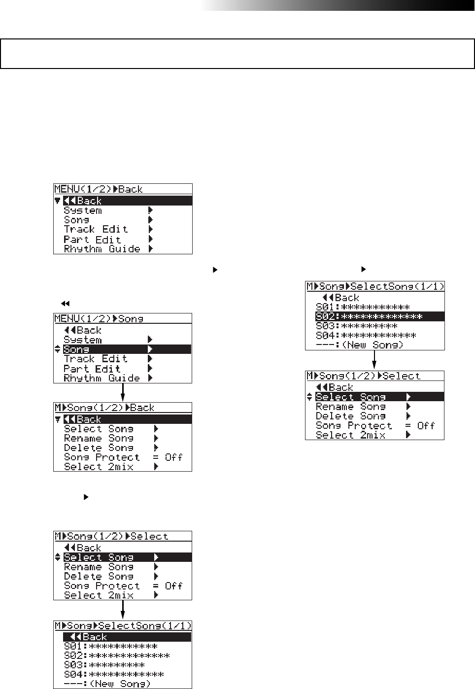
114
MR16 Owner’s Manual (Song management)
The following describes how to select the desired song from the disk when more than one song
is created on the disk. You can also create a new song by the similar procedure. See "Basic
operations" (page 33) for details about how to create a new song.
1) While the recorder is stopped, press the
[MENU/ENTER] knob to enter the menu mode.
The display now shows the first page of the
menu selection screen.
2) Rotate the [MENU/ENTER] knob to select "Song ",
and press the [MENU/ENTER] knob.
The display now shows the song menu screen,
where " Back" is highlighted.
3) Rotate the [MENU/ENTER] knob to select
"Select Song " and press the [MENU/ENTER]
knob.
The display now shows the song list screen.
The screen example above shows that four
songs are currently created on the hard disk.
The song list is shown on a single page.
When more songs are created, the song list
screen has more than one page, and you can
scroll the list by rotating the [MENU/ENTER]
knob.
"- - - :(New Song)" at the bottom of the screen is
used when you create a new song.
4) Rotate the [MENU/ENTER] knob to select the
desired song number/song name, and press the
[MENU/ENTER] knob.
The display returns to the song menu screen,
where "Select Song " is highlighted.
5) Press the [STOP] key to exit the menu mode.
The display shows the home screen of the
selected song.
Selecting the desired song
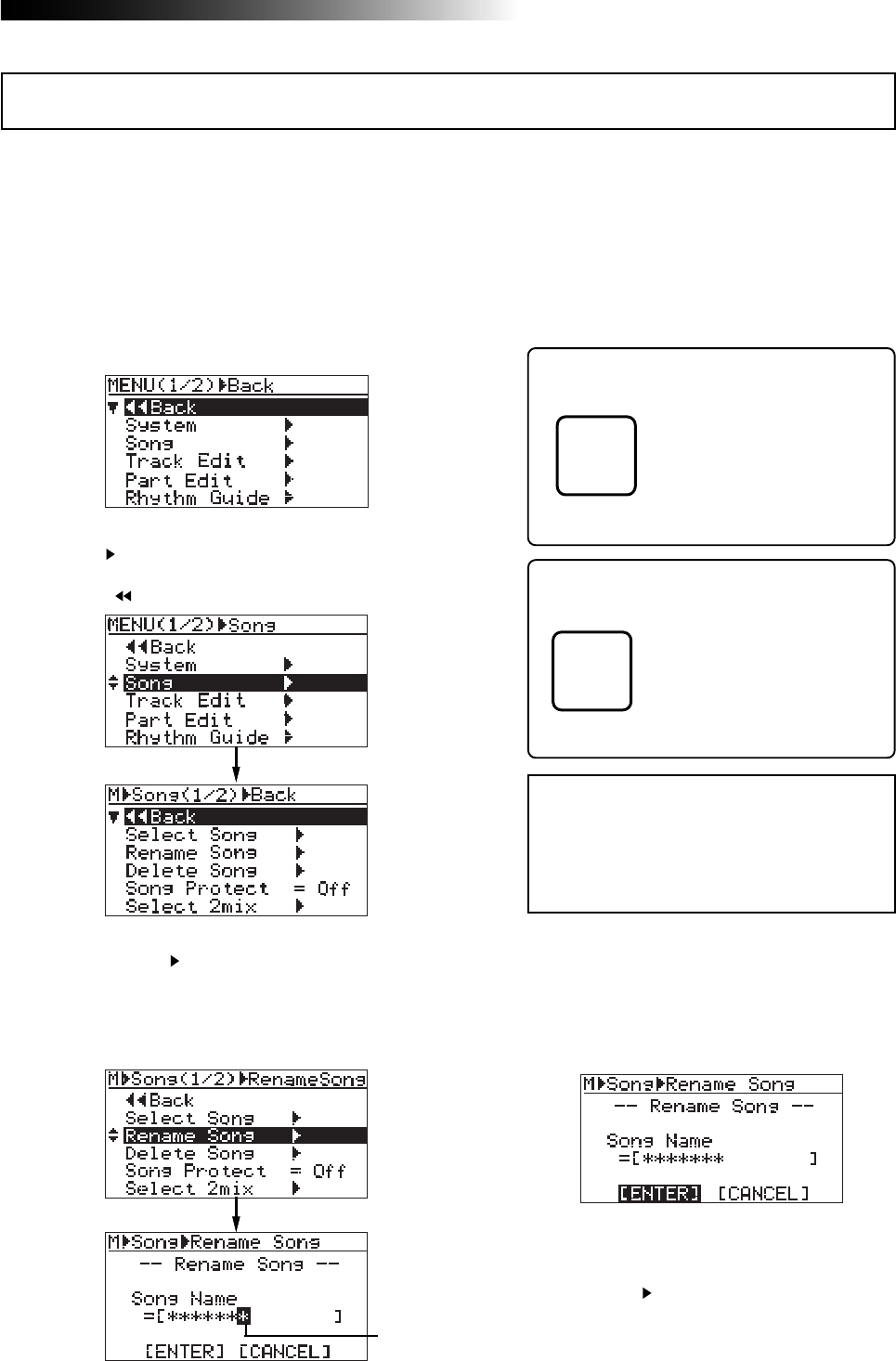
115
MR16 Owner’s Manual (Song management)
You can edit a current song name save the edited song name. Only the current song can be
edited.
1) Load the desired song of which you are going to
edit the song name.
2) While the recorder is stopped, press the
[MENU/ENTER] knob to enter the menu mode.
The display now shows the first page of the
menu selection screen.
6) After entering the name, press the [MENU/ENTER]
knob.
The cursor moves to "[ENTER]" at the bottom
of the screen. To cancel the operation, use the
[MENU/ENTER] knob to highlight “[CANCEL]”
and press the [MENU/ENTER] knob.
<Character entry keys>
[REC SELECT] keys on the
MR16 top panel act as charac-
ter entry keys in the menu
mode. For example, the [REC
SELECT] key for track 1 (shown
on the left) can be used for en-
tering A, B, C, a, b, c and 1.
<Note>:
If you enter the same name as an
existing song or do not enter a name in step
5 and press the [
MENU/ENTER
] knob in step
6 below, the display shows "
Illegal Song
Name!
" and returns to the song name edit-
ing screen.
3) Rotate the [MENU/ENTER] knob to select
"Song ", and press the [MENU/ENTER] knob.
The display now shows the song menu screen,
where " Back" is highlighted.
4) Rotate the [MENU/ENTER] knob to select
"Rename Song ", then press the [MENU/ENTER]
knob.
The display now shows the screen for song
name editing of the current song, on which the
rightmost character of song name flashes.
5) Use the character entry keys to enter the desired
character to the flashing point.
You can move the cursor (flashing point) by
rotating the [MENU/ENTER] knob (or by
pressing another character entry key).
<[DELETE] key>
Pressing the [DELETE] key (the
[REC SELECT] key of the track
15/16) deletes the character at
the flashing point. By pressing
this key repeatedly, you can de-
lete all characters under the
flashing point.
7) Press the [MENU/ENTER] knob again.
The edited name is stored and the display
returns to the song menu screen, where
“Rename Song ” is highlighted.
8) Press the [STOP] key to exit the menu mode.
The MR16 exits the menu mode and the
display shows the home screen where the
edited song name is displayed.
Editing a song name
Flashing
A B C 1
DELETE
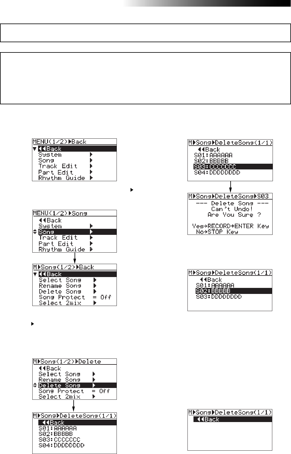
116
MR16 Owner’s Manual (Song management)
<Notes>
• You cannot delete a song which is protected. To delete such a song, release the protection of the song first
(see the next page).
• A deleted song file still remains as a “
hidden file
” on the hard disk. So deleting a song file does not increase
the remaining (recordable) space of the hard disk.
• You can export a “
hidden file
” to your personal computer via USB connection and use it on the computer
(see page 111).
1) While the recorder is stopped, press the
[MENU/ENTER] knob to enter the menu mode.
The display now shows the first page of the menu
selection screen.
5) Press the [MENU/ENTER] knob while holding down
the [RECORD] key.
The selected song is deleted, and the display
returns to the song list screen.
You can delete a song created on the hard disk.
2) Rotate the [MENU/ENTER] knob to select "Song ",
and press the [MENU/ENTER] knob.
The display now shows the song menu screen.
3) Rotate the [MENU/ENTER] knob to select "Delete
Song ", and press the [MENU/ENTER] knob.
The display now shows the list of songs created
on the hard disk, from which you select a song to
be deleted. In the screen example below, five
songs are created so the list has only one page.
4) Rotate the [MENU/ENTER] knob to select a song
to be deleted, and press the [MENU/ENTER] knob.
The display shows warning and confirmation
for deleting the song.
Any song number greater than the song number
of the deleted song is moved up.
In the screen example above, after Song 03 is
deleted, ex-Song 04 is moved up to Song 03 and
ex-Song 05 is moved up to Song 04.
6) Press the [STOP] key to exit the menu mode.
In the example above, the display now shows
the home screen of new Song 03 (ex-Song 04).
If you delete all songs on the hard disk by
repeating the procedure above, ":(New Song)"
is shown. Then, create a new song (see page
33).
Deleting an unnecessary song
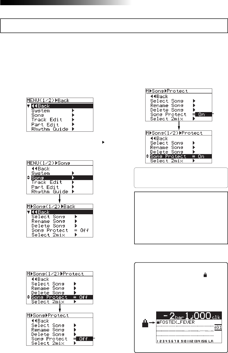
117
MR16 Owner’s Manual (Song management)
You can protect a song to prevent an accidental erasure. The protection can be released when-
ever you want. To keep a recorded song safely, we recommend protecting it. You can make
protection setting only for the current song.
5) Rotate the [MENU/ENTER] knob to select "On",
and press the [MENU/ENTER] knob.
The current song is now protected.
The display returns to the previous screen.
To release the protection, carry out the same pro-
cedure above but select "Off" and press the
[MENU/ENTER] knob in step 5.
1) Load the song you want to protect.
2) While the recorder is stopped, press the
[MENU/ENTER] knob to enter the menu mode.
The display now shows the first page of the
menu selection screen.
3) Rotate the [MENU/ENTER] knob to select "Song ",
and press the [MENU/ENTER] knob.
The display now shows the song menu screen.
4) Rotate the [MENU/ENTER] knob to select
"Protect=***", then press the [MENU/ENTER] knob.
The current option ("On" or "Off") flashes.
The default option is "Off".
Protecting a song
Flashing
Flashing
<Note>:
You cannot make recording or
editing to a protected song. If you want to
make recording or editing to a protected
song, you must release the protection first.
<Note>:
When you set the protection to
"On", all the recording-related keys, such
as the [
REC SELECT
] and [
BOUNCE MODE
]
keys, are turned off.
6) Press the [STOP] key to exit the menu mode.
<Tips>
When the protected song is loaded, “ ” is shown
in the upper left corner of the Home screen (in-
dicated by the arrow in the screen example be-
low).
When this icon is shown, you cannot make re-
cording or edit the song.

118
MR16 Owner’s Manual (Song management)
119
MR16 Owner’s Manual (Track editing)
Track editing
This chapter describes how to edit whole data of a selected (mono or
stereo) track. Track editing does not consume the hard disk space.
Therefore, the remaining space of the disk does not change by executing
track editing.
<Undo/redo of track editing>
By pressing the [UNDO/REDO] key after executing track editing, you can
undo the editing. By pressing the [UNDO/REDO] key after the undo opera-
tion, you can return the track(s) to the condition after being edited.
UNDO/REDO
<Notes>
Also note that, if you carry out any of the following
after editing, you cannot undo the editing anymore.
1. Making new recording
2. Making new editing
3. Turning off the power
4. Loading another song
<Notes>
While a menu screen is shown, you can go up the menu screen level or
directly exit the menu mode by the following operations.
(1) Select “ Back” on a menu screen and press the [MENU/ENTER] knob.
The display returns to the previous (upper level) screen.
Repeating this operation finally exits the menu mode.
(2) Press the [REWIND] key.
The display returns to the previous (upper level) screen.
Repeating this operation finally exits the menu mode.
(3) Press the [STOP] key.
The menu mode exits and the display shows the home screen.
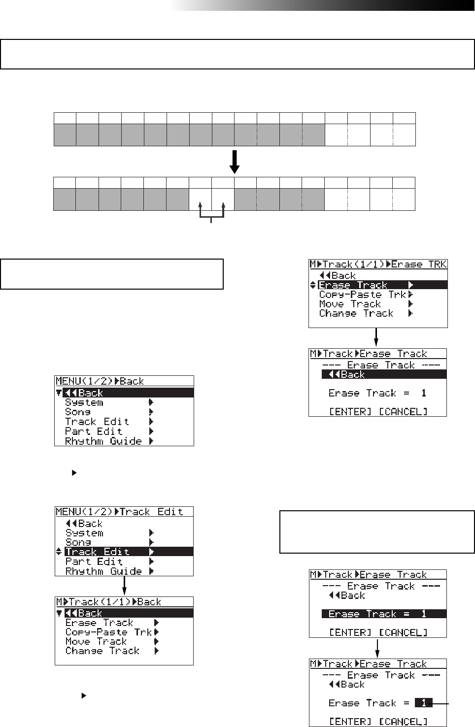
120
MR16 Owner’s Manual (Track editing)
5) Rotate the [MENU/ENTER] knob to select
"Erase Track = *", and press the [MENU/ENTER]
knob.
The currently selected option flashes and you
can now select the desired option by rotating
the [MENU/ENTER] knob. The available options
are:
You can erase whole data (from ABS ZERO to REC END) of the desired track(s) of the song cur-
rently loaded.
1) Load the song you want to edit.
2) While the recorder is stopped, press the
[MENU/ENTER] knob to enter the menu mode.
The display now shows the first page of the
menu selection screen.
4) Rotate the [MENU/ENTER] knob to select
"Erase Track ", and press the [MENU/ENTER]
knob.
The display now shows the screen for
selecting the track(s) to be erased.
<Note>:
You cannot erase track data of a song pro-
tected.
3) Rotate the [MENU/ENTER] knob to select
"Track Edit ", and press the [MENU/ENTER] knob.
The display now shows the track edit menu
screen.
Erasing track data
Flashing
Trk 1 Trk 2 Trk 3 Trk 4 Trk 5 Trk 6 Trk 7 Trk 8 Trk 9 Trk 10 Trk 11 Trk 12 Trk 13 Trk 14 Trk 15 Trk 16
Trk 1 Trk 2 Trk 3 Trk 4 Trk 5 Trk 6 Trk 7 Trk 8 Trk 9 Trk 10 Trk 11 Trk 12 Trk 13 Trk 14 Trk 15 Trk 16
Deleting data of tracks 7 and 8.
• 1 through 8 (mono track)
• 1/2, 3/4, 5/6, 7/8, 9/10, 11/12, 13/14 and 15/16
(stereo tracks)
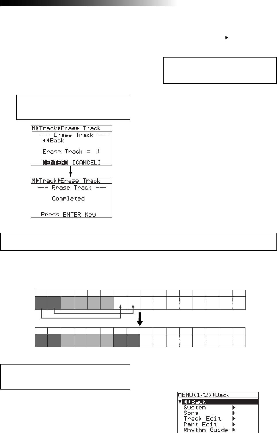
121
MR16 Owner’s Manual (Track editing)
8) Press the [MENU/ENTER] knob.
The display now returns to the track edit menu
screen, where “Erase Track ” is highlighted.
9) Press the [STOP] key to exit the menu mode.
You can copy whole data (from ABS ZERO to REC END) of the desired track(s) of the song cur-
rently loaded and paste it to the other desired track(s). The data on the source track(s) still
remains after the copy/paste operation. Copy/paste operation can be done within the currently
loaded song.
<Note>:
You cannot copy/paste track data of a song
protected. Release the protection before copying/
pasting track data.
<Note>:
If you are not satisfied with the
result, press the [
UNDO/REDO
] key to undo
the operation (see page 119).
1) Load the song you want to edit.
<Note>:
If you want to cancel the erase op-
eration, move the cursor to "
[CANCEL]
" on
the screen, and press the [
MENU/ENTER
] knob.
6) Rotate the [MENU/ENTER] knob to select the
desired option, and press the [MENU/ENTER] knob.
“Erase Track = *” is now highlighted on the
screen.
7) Rotate the [MENU/ENTER] knob to move the
cursor to "[ENTER]" on the screen, and press the
[MENU/ENTER] knob.
The display shows "Please Wait", immediately
followed by "Completed" when the MR16
completes erasing.
Copying/pasting track data
Trk 1 Trk 2 Trk 3 Trk 4 Trk 5 Trk 6 Trk 7 Trk 8 Trk 9 Trk 10 Trk 11 Trk 12 Trk 13 Trk 14 Trk 15 Trk 16
Trk 1 Trk 2 Trk 3 Trk 4 Trk 5 Trk 6 Trk 7 Trk 8 Trk 9 Trk 10 Trk 11 Trk 12 Trk 13 Trk 14 Trk 15 Trk 16
AB
ABAB
2) While the recorder is stopped, press the
[MENU/ENTER] knob to enter the menu mode.
The display now shows the first page of the
menu selection screen.
Pasting data of tracks 1/2 to tracks 7/8.
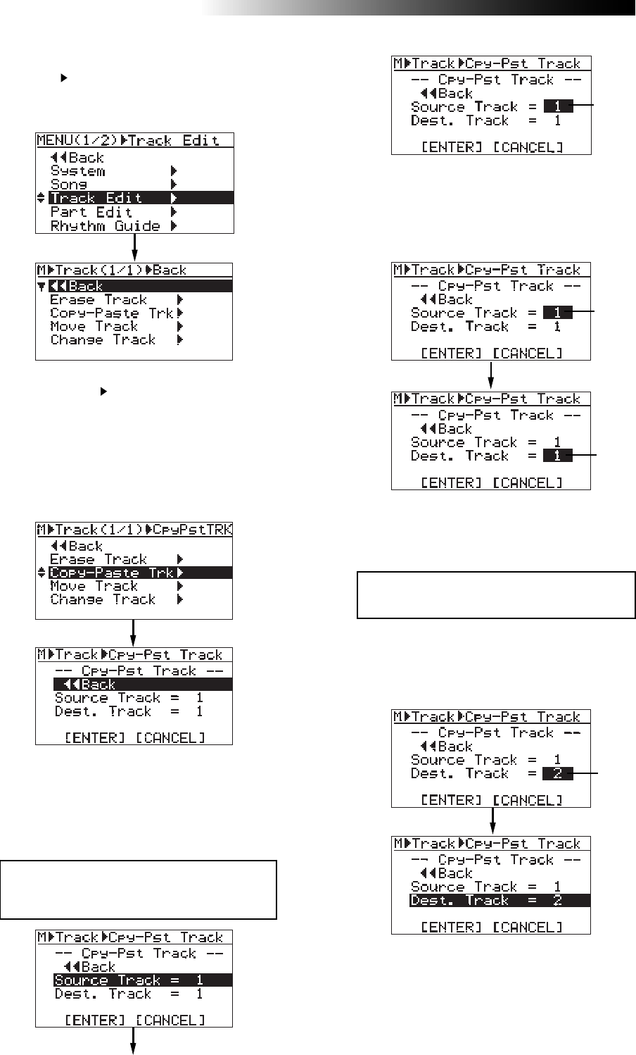
122
MR16 Owner’s Manual (Track editing)
5) Rotate the [MENU/ENTER] knob to select
"Source Track = *", and press the [MENU/ENTER]
knob.
You can now select the desired copy source
track(s) by rotating the [MENU/ENTER] knob.
The available options are:
7) Rotate the [MENU/ENTER] knob to select the
destination track(s), and press the [MENU/ENTER]
knob.
“Dest. Track = *” is now highlighted on the screen.
<Note>:
You cannot select the same track(s)
for the copy source and destination.
8) Rotate the [MENU/ENTER] knob to move the
cursor to "ENTER" at the bottom of the screen,
then press the [MENU/ENTER] knob.
The display shows "Please Wait", immediately
followed by "Completed" when the MR16
completes the copy/paste operation.
You can select the same number of tracks as
the copy source track(s). For example, if you
select a mono track for the source, you can
only select a mono track for the destination.
6) Rotate the [MENU/ENTER] knob to select the
source track(s) to be copied, and press the
[MENU/ENTER] knob.
You can now select the desired copy
destination track(s)
Flashing
Flashing
Flashing
Flashing
3) Rotate the [MENU/ENTER] knob to select
"Track Edit ", and press the [MENU/ENTER] knob.
The display now shows the track edit menu
screen.
4) Rotate the [MENU/ENTER] knob to select
"Copy-Paste Track ", and press the [MENU/ENTER]
knob.
The display now shows the screen for selecting
the source track(s) and destination track(s) of
copy/paste operation.
"Source Track" selects the copy source track(s),
while "Dest. Track" selects the paste destination
track(s).
• 1 through 8 (mono track)
• 1/2, 3/4, 5/6, 7/8, 9/10, 11/12, 13/14 and 15/16
(stereo tracks)
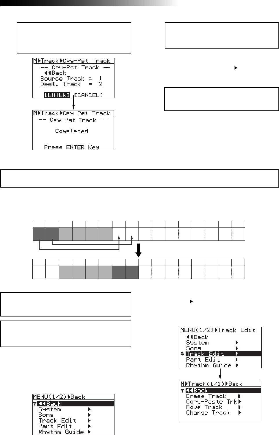
123
MR16 Owner’s Manual (Track editing)
9) Press the [MENU/ENTER] knob.
The display now returns to the track edit menu
screen, where “Copy-Paste Trk ” is highlighted.
10) Press the [STOP] key to exit the menu mode.
<Note>:
If a destination track has recorded
data, pasting the copied data overwrites the
previous data.
<Note>:
If you want to cancel the copy/paste
operation, move the cursor to "
[CANCEL]
" on
the screen, and press the [
MENU/ENTER
]
knob.
<Note>:
If you are not satisfied with the re-
sult, press the [
UNDO/REDO
] key to undo the
operation (see page 119).
You can move whole data (from ABS ZERO to REC END) of the desired track(s) to the other
desired track(s). After the data is moved, the original track(s) is(are) silent. You can only move
track data within the current song.
Moving track data
Trk 1 Trk 2 Trk 3 Trk 4 Trk 5 Trk 6 Trk 7 Trk 8 Trk 9 Trk 10 Trk 11 Trk 12 Trk 13 Trk 14 Trk 15 Trk 16
Trk 1 Trk 2 Trk 3 Trk 4 Trk 5 Trk 6 Trk 7 Trk 8 Trk 9 Trk 10 Trk 11 Trk 12 Trk 13 Trk 14 Trk 15 Trk 16
AB
AB
<Note>:
Unlike the copy/paste operation, the data
on the source track(s) disappears after the move
operation.
1) Load the song you want to edit.
2) While the recorder is stopped, press the
[MENU/ENTER] knob to enter the menu mode.
The display now shows the first page of the
menu selection screen.
3) Rotate the [MENU/ENTER] knob to select
"Track Edit ", and press the [MENU/ENTER] knob.
The display now shows the track edit menu
screen.
<Note>:
You cannot move track data of a song pro-
tected. Release the protection before moving track
data.
Moving data of tracks 1/2 to tracks 7/8.
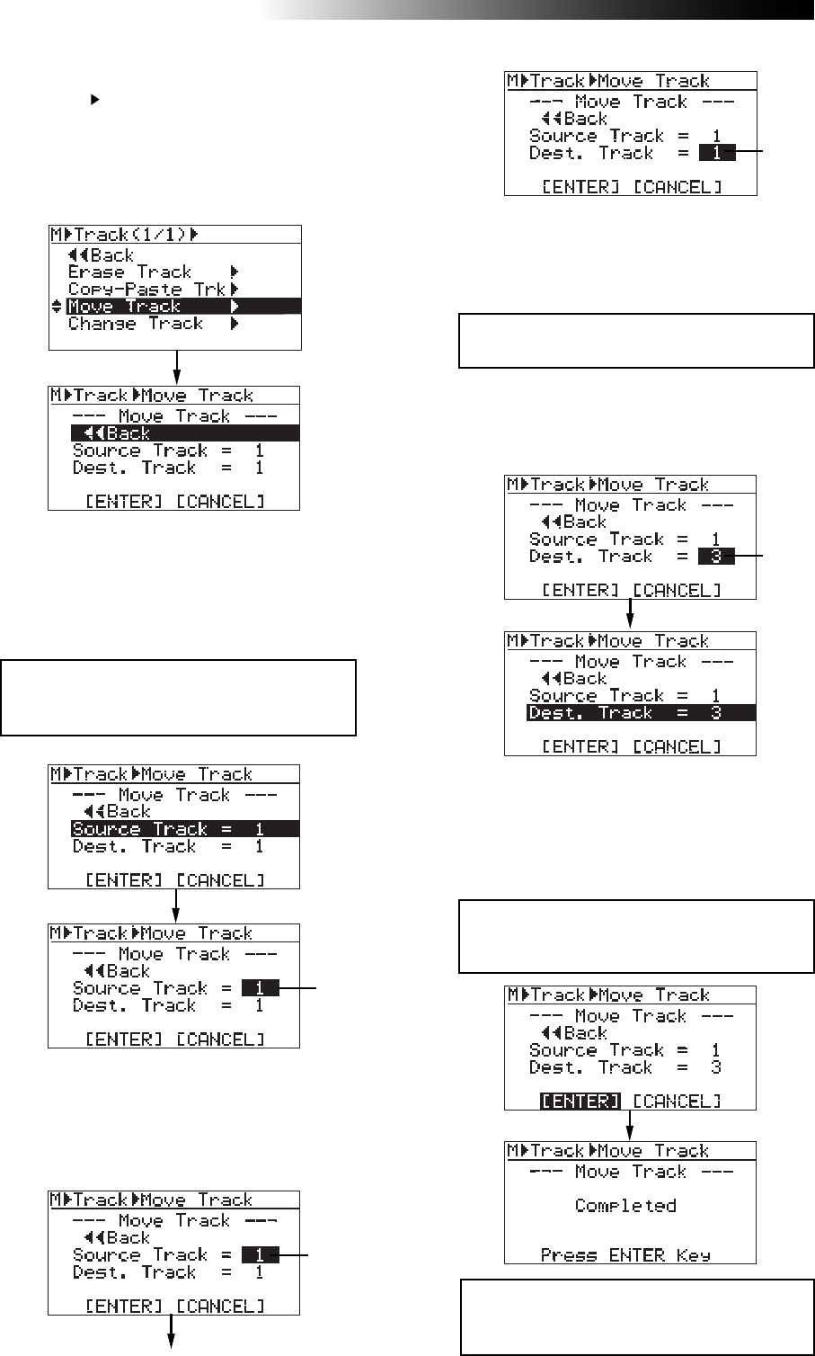
124
MR16 Owner’s Manual (Track editing)
<Note>:
If you want to cancel the move opera-
tion, move the cursor to "
[CANCEL]
" on the
screen, and press the [
MENU/ENTER
] knob.
<Note>:
If a destination track has recorded
data, moving data overwrites the previous
data.
<Note>:
You cannot select the same track(s)
for the move source and destination.
You can select the same number of tracks as
the move source track(s). For example, if you
select a mono track for the move source, you
can only select a mono for the move destina-
tion.
8) Rotate the [MENU/ENTER] knob to move the
cursor to "[ENTER]" on the screen, and press the
[MENU/ENTER] knob.
The display shows "Please Wait", immediately
followed by "Completed" when the MR16
completes the move operation.
7) Rotate the [MENU/ENTER] knob to select
destination track(s), and press the
[MENU/ENTER] knob.
“Dest. Track = *” is now highlighted on the screen.
Flashing
5) Rotate the [MENU/ENTER] knob to select "Source
Track = *", and press the [MENU/ENTER] knob.
You can now select the desired move source
track(s) by rotating the [MENU/ENTER] knob.
The available options are:
6) Rotate the [MENU/ENTER] knob to select source
track(s), and press the [MENU/ENTER] knob.
You can now select the desired destination
track(s).
4) Rotate the [MENU/ENTER] knob to select
"Move Track ", and press the [MENU/ENTER] knob.
The display now shows the screen for selecting
the source track(s) and destination track(s) of
the move operation. "Source Track" selects the
move source track(s), while "Dest. Track" selects
the move destination track(s).
Flashing
Flashing
Flashing
• 1 through 8 (mono track)
• 1/2, 3/4, 5/6, 7/8, 9/10, 11/12, 13/14 and 15/16
(stereo tracks)
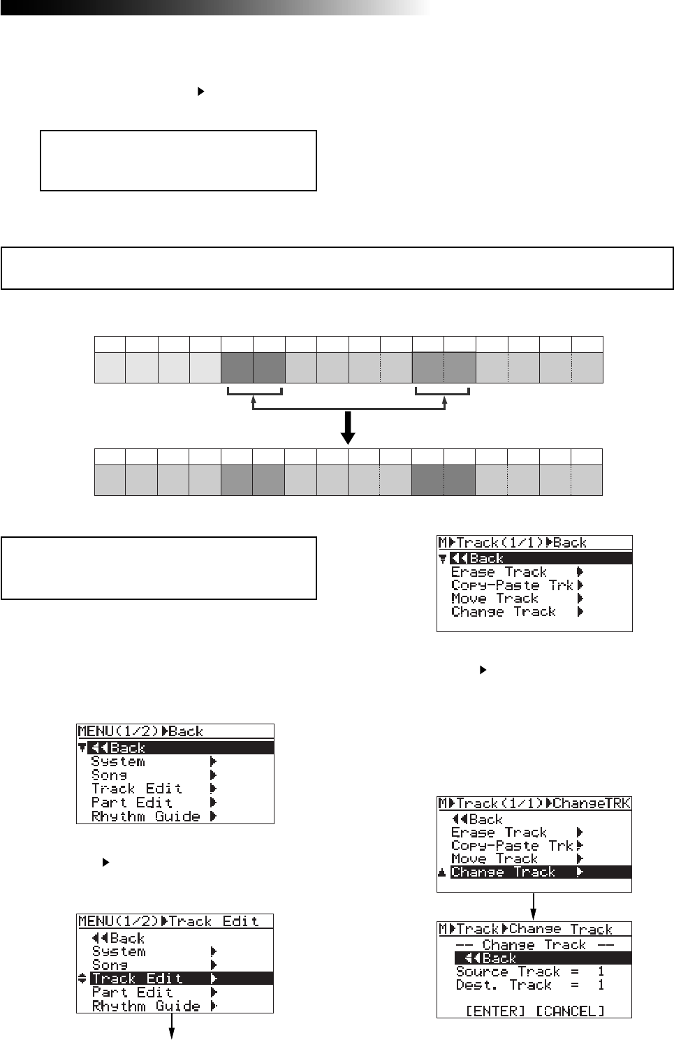
125
MR16 Owner’s Manual (Track editing)
You can exchange whole data (from ABS ZERO to REC END) between the desired track(s).
<Note>:
You cannot exchange track data of a song
protected. Release the protection before exchang-
ing track data.
9) Press the [MENU/ENTER] knob.
The display now returns to the track edit menu
screen, where “Move Track ” is highlighted.
10) Press the [STOP] key to exit the menu mode.
<Note>:
If you are not satisfied with the re-
sult, press the [
UNDO/REDO
] key to undo the
operation (see page 119).
1) Load the song you want to edit.
2) While the recorder is stopped, press the
[MENU/ENTER] knob to enter the menu mode.
The display now shows the first page of the
menu selection screen.
3) Rotate the [MENU/ENTER] knob to select
"Track Edit ", and press the [MENU/ENTER] knob.
The display now shows the track edit menu
screen.
Exchanging whole track data
Trk 1 Trk 2 Trk 3 Trk 4 Trk 5 Trk 6 Trk 7 Trk 8 Trk 9 Trk 10 Trk 11 Trk 12 Trk 13 Trk 14 Trk 15 Trk 16
Trk 1 Trk 2 Trk 3 Trk 4 Trk 5 Trk 6 Trk 7 Trk 8 Trk 9 Trk 10 Trk 11 Trk 12 Trk 13 Trk 14 Trk 15 Trk 16
AB
AB
CD
CD
4) Rotate the [MENU/ENTER] knob to select
"Change Track ", and press the [MENU/ENTER]
knob.
The display now shows the screen for select-
ing the source track(s) and destination track(s)
of the exchange operation.
"Source Track" selects the exchange source
track(s), while "Dest. Track" selects the exchange
destination track(s).
Exchanging data between tracks 5/6 and tracks 11/12.
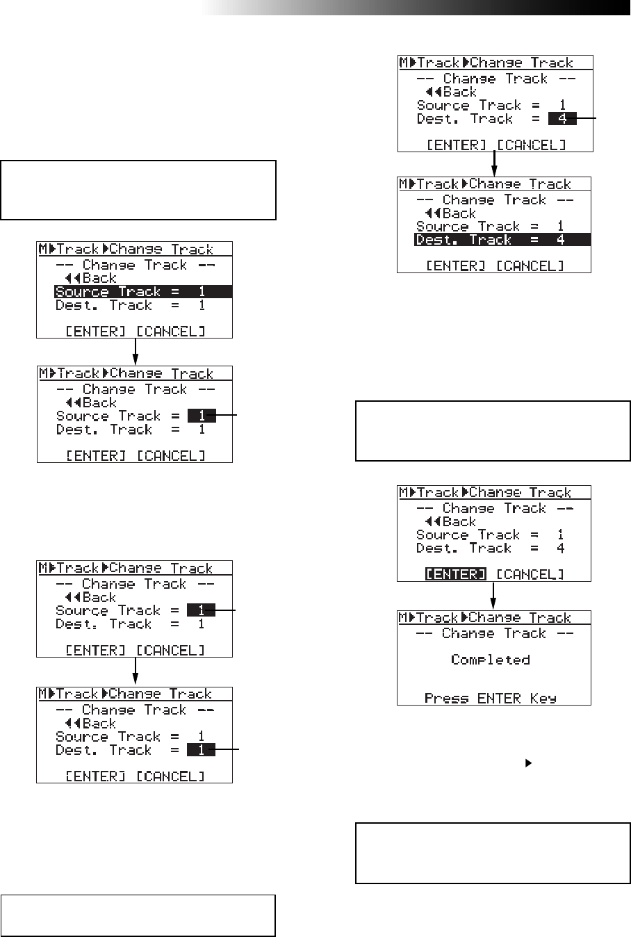
126
MR16 Owner’s Manual (Track editing)
9) Press the [MENU/ENTER] knob.
The display now returns to the track edit menu
screen, where “Change Track ” is highlighted.
10) Press the [STOP] key to exit the menu mode.
<Note>:
If you are not satisfied with the re-
sult, press the [
UNDO/REDO
] key to undo the
operation (see page 119).
5) Rotate the [MENU/ENTER] knob to select
"Source Track = *", and press the [MENU/ENTER]
knob.
You can now select the desired exchange source
track(s) by rotating the [MENU/ENTER] knob.
The available options are:
6) Rotate the [MENU/ENTER] knob to select the
source track(s), and press the [MENU/ENTER] knob.
You can now select the desired destination
track(s).
<Note>:
If you want to cancel the exchange op-
eration, move the cursor to "
[CANCEL]
" on the
screen, and press the [
MENU/ENTER
] knob.
<Note>:
You cannot select the same track(s)
for the exchange source and destination.
8) Rotate the [MENU/ENTER] knob to move the
cursor to "[ENTER]" on the screen, and press the
[MENU/ENTER] knob.
The display shows "Please Wait", immediately
followed by "Completed" when the MR16
completes the exchange operation.
You can select the same number of tracks as
the exchange source track(s). For example, if
you select a mono track for the exchange
source, you can only select a mono track for
the exchange destination.
7) Rotate the [MENU/ENTER] knob to select the
destination track(s), and press the
[MENU/ENTER] knob.
“Dest. Track = *” is now highlighted on the screen.
Flashing
Flashing
Flashing
Flashing
• 1 through 8 (mono track)
• 1/2, 3/4, 5/6, 7/8, 9/10, 11/12, 13/14 and 15/16
(stereo tracks)
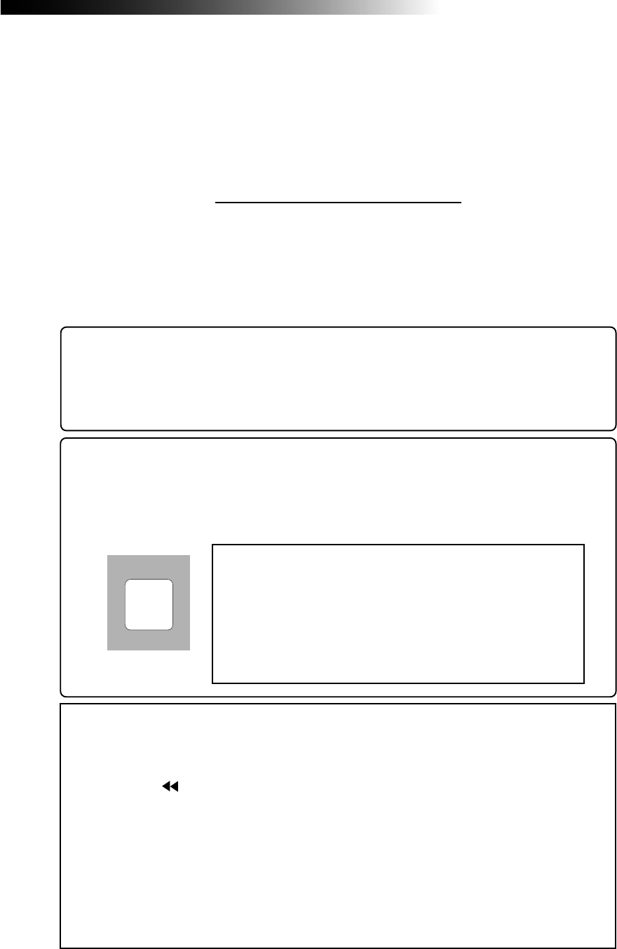
127
MR16 Owner’s Manual (Part editing)
Part editing
This chapter describes how to edit a "part" (*) of recorded song.
You can edit data of a track or tracks between the "LOCATE A" and "LO-
CATE B" points. Part editing does not consume the hard disk space.
Therefore, the remaining space of the disk does not change by executing
part editing.
<Undo/redo of editing>
You can undo part editing. By pressing the [UNDO/REDO] key after executing part
editing, the song returns to the original condition before editing.
By pressing the [UNDO/REDO] key after undoing part editing, you can again return
the song to the condition after being edited.
<Notes>
Also note that if you carry out any of the following after
editing, you cannot undo the editing anymore.
1. Making new recording
2. Making new editing
3. Turning off the power
4. Loading another song
UNDO/REDO
[UNDO/REDO] key
<(*) About "part">
A "part" is defined as audio data between the "LOCATE A" and "LOCATE B" points.
You can edit a "part" as described later.
Therefore, before carrying out part editing, the "LOCATE A" and "LOCATE B" points
must be set. See page 53 for details about how to set these points.
<Notes>
While a menu screen is shown, you can go up the menu screen level or directly exit
the menu mode by the following operations.
(1) Select “ Back” on a menu screen and press the [MENU/ENTER] knob.
The display returns to the previous (upper level) screen.
Repeating this operation finally exits the menu mode.
(2) Press the [REWIND] key.
The display returns to the previous (upper level) screen.
Repeating this operation finally exits the menu mode.
(2) Press the [STOP] key.
The menu mode exits and the display shows the home screen.
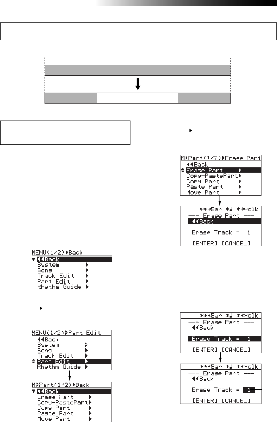
128
MR16 Owner’s Manual (Part editing)
<Note>:
You cannot erase the part(s) of a song
which is protected. Release the song protection
before erasing the part(s).
1) Load the song you want to edit.
2) Set the LOCATE A and LOCATE B points (see
page 53).
You can check the part(s) by playing back the
recorder between the LOCATE A and LOCATE
B points (see page 48).
3) While the recorder is stopped, press the
[MENU/ENTER] knob to enter the menu mode.
The display now shows the first page of the
menu selection screen.
4) Rotate the [MENU/ENTER] knob to select
"Part Edit ", and press the [MENU/ENTER] knob.
The display now shows the part edit menu
screen.
5) Rotate the [MENU/ENTER] knob to select
"Erase Part ", and press the [MENU/ENTER] knob.
The display now shows the screen for
selecting a track or tracks of which you want
to erase the part(s).
6) Rotate the [MENU/ENTER] knob to select "Erase
Track = *", and press the [MENU/ENTER] knob.
The current option starts flashing and you can
now select the desired track(s) by rotating the
[MENU/ENTER] knob. The available options are:
• 1 through 8 (mono track)
• 1/2, 3/4, 5/6, 7/8, 9/10, 11/12, 13/14 and 15/16
(stereo tracks)
7) Rotate the [MENU/ENTER] knob to select the
desired option, and press the [MENU/ENTER] knob.
The display returns to the previous screen.
You can erase the part(s) on the selected track(s) of the current song.
Erasing the part(s)
Flashing
Locate A point Locate B point
ABS ZERO REC END
You can delete the desired part(s) on the desired track(s).
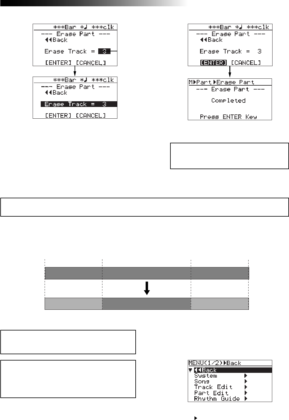
129
MR16 Owner’s Manual (Part editing)
You can copy the desired part(s) of the selected track(s) and paste it(them) to the same time
position of the other desired track(s). The copy/paste operation of a part or parts can be made
only within the current song. You can also make the copy/paste operation of a part or parts
using another method described later in "Copying/pasting the desired part(s)-2".
1) Load the song you want to edit.
2) Set the LOCATE A and LOCATE B points for
specifying the desired part(s) (see page 53).
You can check the part(s) by playing back
between the LOCATE A and LOCATE B points
(see page 48).
<Note>:
You cannot copy/paste track data of a song
protected. Release the protection before making
the copy/paste operation.
4) Rotate the [MENU/ENTER] knob to select
"Part Edit ", and press the [MENU/ENTER] knob.
The display now shows the part edit menu
screen.
<Note>:
If you want to paste the copied part(s) to
the desired time position of other track(s) other
than the position between the LOCATE A and LO-
CATE B points, use the method described later in
"
Copying/pasting the desired part(s)-2
".
9) After pressing the [MENU/ENTER] knob, press
the [STOP] key to exit the MENU mode.
<Note>:
If you are not satisfied with the re-
sult, press the [
UNDO/REDO
] key to undo the
operation (see page 127).
8) Rotate the [MENU/ENTER] knob to move the
cursor to "[ENTER]" on the screen, and press the
[MENU/ENTER] knob.
The display shows "Please Wait", immediately
followed by "Completed" when the MR16
completes erasing.
If you want to cancel the part erase operation,
move the cursor to "[CANCEL]" on the screen,
and press the [MENU/ENTER] knob.
3) While the recorder is stopped, press the
[MENU/ENTER] knob to enter the menu mode.
The display now shows the first page of the
menu selection screen.
Copying/pasting the desired part(s)-1
Flashing
Locate A point Locate B point
ABS ZERO REC END
You can copy and paste the desired part(s) on the desired track(s) into the other desired track(s).
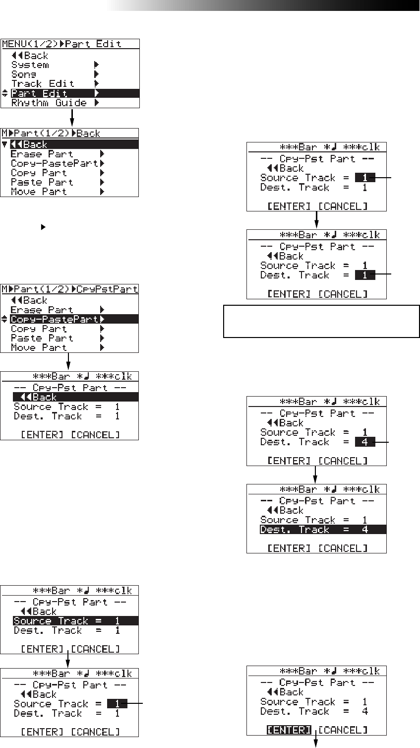
130
MR16 Owner’s Manual (Part editing)
6) Rotate the [MENU/ENTER] knob to select
"Source Track = *", and press the [MENU/ENTER]
knob.
The display now shows the screen for
selecting the copy source track(s). You can
select the copy source track(s) by rotating the
[MENU/ENTER] knob. The available options are:
• 1 through 8 (mono track)
• 1/2, 3/4, 5/6, 7/8, 9/10, 11/12, 13/14 and 15/16
(stereo tracks)
7) Rotate the [MENU/ENTER] knob to select the source
track(s) to be copied, and press the [MENU/ENTER]
knob.
You can select the destination track(s) by
rotating the [MENU/ENTER] knob.
You can select the same number of tracks as the
paste source track(s). For example, if you select a
mono track for the copy source, you can only
select a mono track for paste destination.
5) Rotate the [MENU/ENTER] knob to select
"Copy-PastePart ", and press the
[MENU/ENTER] knob.
The display now shows the screen for
selecting the source track(s) and destination
track(s) of copy/paste.
Flashing
Flashing
Flashing
<Note>:
You cannot select the same track(s)
for the copy source and destination.
9) Rotate the [MENU/ENTER] knob to move the
cursor to "[ENTER]" at the bottom of the screen,
then press the [MENU/ENTER] knob.
The display shows "Please Wait", immediately
followed by "Completed" when the MR16
completes the copy/paste operation.
To cancel the copy/paste operation, move the
cursor to "[CANCEL]" at the bottom of the
screen, and press the [MENU/ENTER] knob.
8) Rotate the [MENU/ENTER] knob to select the
destination track(s), and press the [MENU/ENTER]
knob.
The display returns to the previous screen.
Flashing
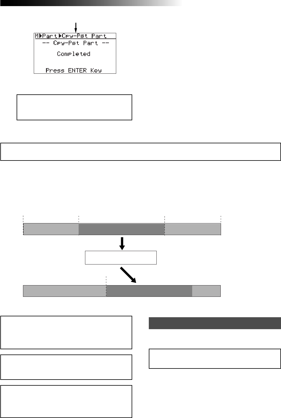
131
MR16 Owner’s Manual (Part editing)
You can copy the desired part(s) of the selected track(s) and paste it(them) to the other time
position of the desired track(s). Unlike the method described above in "Copying/pasting the de-
sired part(s)-1", the part data is copied to the (virtual) clipboard and then pasted to the specified
position of the other specified track(s).
The copy/paste operation of a part or parts can be made only within the current song.
<Note>:
You cannot copy/paste track data of a song
protected. Release the protection before making
the copy/paste operation.
<Note>:
If you paste the part(s) to the same time
position of the other track(s), we recommend us-
ing the method described above in "
Copying/past-
ing the desired part(s)-1
", because it works faster.
Copying/pasting the desired part(s)-2
10) After pressing the [MENU/ENTER] knob, press
the [STOP] key to exit the MENU mode.
<Note>:
If you are not satisfied with the re-
sult, press the [
UNDO/REDO
] key to undo the
operation (see page 127).
<Note>:
If you turn off the MR16 after copying
the part data to the clipboard, the data on the
clipboard is lost. Also note that you cannot undo
copying data to the clipboard.
Locate A point Locate B point
ABS ZERO REC END
Locate A point
ClipBoard (Virtual)
1) Load the song you want to edit.
2) Set the LOCATE A and LOCATE B points (see
page 53).
You can check the edited part(s) by playing
back between the LOCATE A and LOCATE B
points (see page 48).
Copying to the clipboard
<Note>:
You cannot undo/redo copying to the clip-
board.
Firstly, you must copy the desired part data to the
clipboard.
You can copy and paste the desired part(s)
on the desired track(s) into the desired time
position on the other desired track(s).
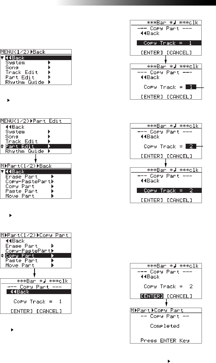
132
MR16 Owner’s Manual (Part editing)
3) While the recorder is stopped, press the
[MENU/ENTER] knob to enter the menu mode.
The display now shows the first page of the
menu selection screen.
4) Rotate the [MENU/ENTER] knob to select
"Part Edit ", and press the [MENU/ENTER] knob.
The display now shows the part edit menu
screen.
5) Rotate the [MENU/ENTER] knob to select
"Copy Part ", and press the [MENU/ENTER] knob.
The display now shows the screen for selecting
the source track(s).
6) Rotate the [MENU/ENTER] knob to select
"Copy Track ", and press the [MENU/ENTER] knob.
The display now shows the screen for selecting
the copy source track(s). You can select the copy
source track(s) by rotating the [MENU/ENTER]
knob. The available options are:
• 1 through 8 (mono track)
• 1/2, 3/4, 5/6, 7/8, 9/10, 11/12, 13/14 and 15/16
(stereo tracks)
8) Rotate the [MENU/ENTER] knob to move the
cursor to "[ENTER]" at the bottom of the screen,
then press the [MENU/ENTER] knob.
The display shows "Please Wait", immediately
followed by "Completed" when the MR16
completes the part copy operation.
To cancel the part copy operation, move the
cursor to "[CANCEL]" at the bottom of the
screen, and press the [MENU/ENTER] knob.
7) Rotate the [MENU/ENTER] knob to select the track(s)
to be copied, and press the [MENU/ENTER] knob.
The display returns to the previous screen.
Flashing
Flashing
9) Press the [MENU/ENTER] knob.
The display now returns to the part edit menu
screen, where “Copy Part ” is highlighted.
The procedure example below shows how to
paste the copied part data on the clipboard to
the LOCATE A point of the selected track.
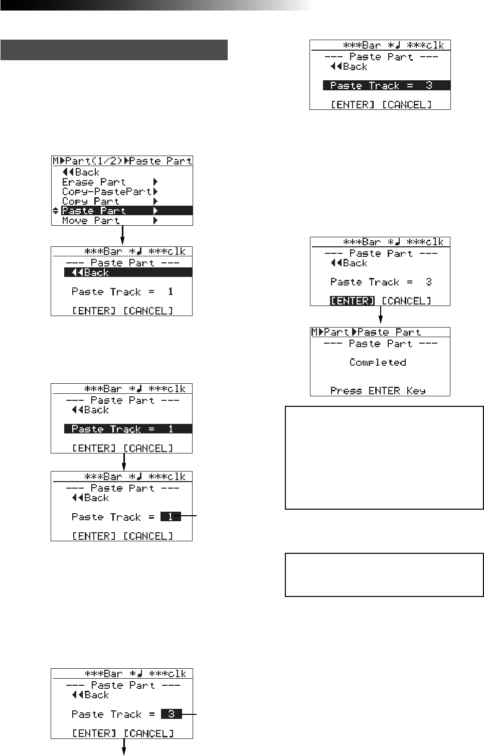
133
MR16 Owner’s Manual (Part editing)
<Note>:
If you are going to carry out the
paste operation when no data is pasted on
the clipboard, the error message (“
Clipboard
Empty!
) is shown on the display and the
MR16 does not accept the operation.
Press the [
STOP
] key to exit the menu mode
and copy the desired data to the clipboard
before carrying out the paste operation.
<Note>:
If you are not satisfied with the re-
sult, press the [
UNDO/REDO
] key to undo the
operation (see page 127).
3) Rotate the [MENU/ENTER] knob to select the
paste destination track(s), and press the
[MENU/ENTER] knob.
The display returns to the previous screen.
4) Rotate the [MENU/ENTER] knob to move the
cursor to "[ENTER]" on the screen, and press the
[MENU/ENTER] knob.
The display shows "Please Wait", immediately
followed by "Completed" when the MR16
completes the paste operation.
If you want to cancel the part paste operation,
move the cursor to "[CANCEL]" on the screen,
and press the [MENU/ENTER] knob.
Flashing
Flashing
The following procedure is assumed that the
LOCATE A point, the paste destination, is set
Pasting clipboard data
1) Rotate the [MENU/ENTER] knob to select
"Paste Part >", and press the [MENU/ENTER] knob.
The display now shows the screen for
selecting the paste destination track(s).
2) Rotate the [MENU/ENTER] knob to select
"Paste Track = *", and press the [MENU/ENTER]
knob.
You can now select the desired paste destination
track(s) by rotating the [MENU/ENTER] knob.
5) After pressing the [MENU/ENTER] knob, press
the [STOP] key to exit the MENU mode.
You can select the same number of tracks as the
paste destination track(s). For example, if you
select a mono track for the copy source, you can
only select a mono track for paste destination.
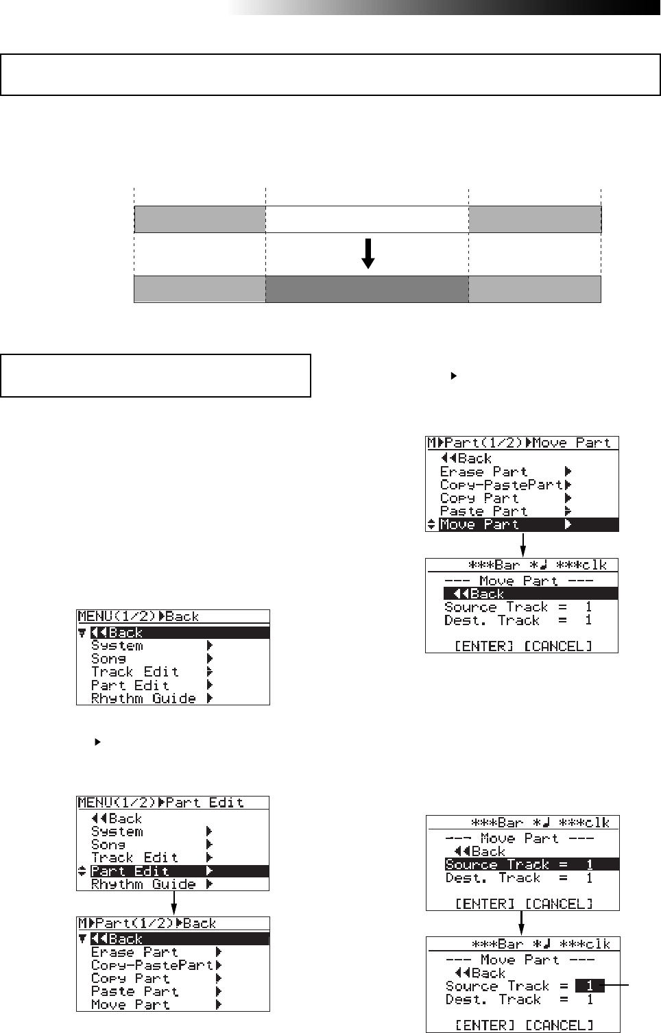
134
MR16 Owner’s Manual (Part editing)
You can move the desired part(s) of the desired track(s) to the other desired track(s).
The part move operation can be made only within the current song. After the part move opera-
tion is carried out, the source part(s) becomes silent.
<Note>:
You cannot move data of a song protected.
Release the protection before moving data.
1) Load the song you want to edit.
2) Set the LOCATE A and LOCATE B points (see
page 53).
You can check the part(s) by playing back
between the LOCATE A and LOCATE B points
(see page 48).
3) While the recorder is stopped, press the
[MENU/ENTER] knob to enter the menu mode.
The display now shows the first page of the
menu selection screen.
4) Rotate the [MENU/ENTER] knob to select
"Part Edit ", and press the [MENU/ENTER] knob.
The display now shows the part edit menu
screen.
5) Rotate the [MENU/ENTER] knob to select
"Move Part ", and press the [MENU/ENTER] knob.
The display now shows the screen for
selecting the source track(s) and destination
track(s) of the move operation.
6) Rotate the [MENU/ENTER] knob to select
"Source Track = *", and press the [MENU/ENTER]
knob.
You can now select the move source track(s)
by rotating the [MENU/ENTER] knob.
The available options are:
• 1 through 8 (mono track)
• 1/2, 3/4, 5/6, 7/8, 9/10, 11/12, 13/14 and 15/16
(stereo tracks)
Moving the part(s)
Locate A point Locate B point
ABS ZERO REC END
You can move the desired part(s) on the desired track(s) to the other desired track(s).
Flashing
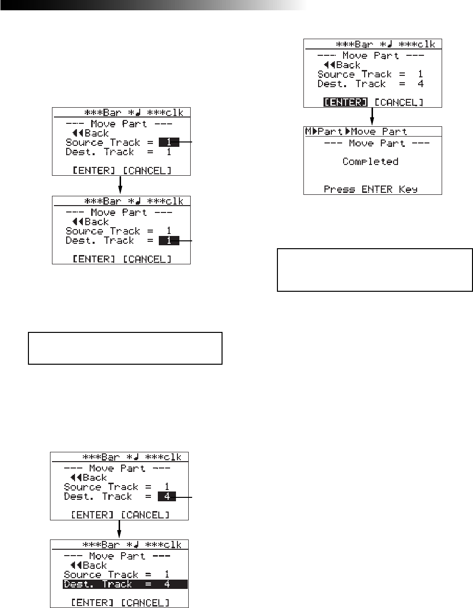
135
MR16 Owner’s Manual (Part editing)
9) Rotate the [MENU/ENTER] knob to move the
cursor to "[ENTER]" on the screen, and press the
[MENU/ENTER] knob.
The display shows "Please Wait", immediately
followed by "Completed" when the MR16
completes the move operation.
<Note>:
If you are not satisfied with the re-
sult, press the [
UNDO/REDO
] key to undo the
operation (see page 127).
8) Rotate the [MENU/ENTER] knob to select the
destination track(s), and press the
[MENU/ENTER] knob.
The display returns to the screen where
"Dest. Track = *" is highlighted.
If you want to cancel the move operation, move
the cursor to "[CANCEL]" on the screen, and
press the [MENU/ENTER] knob.
Flashing
Flashing
Flashing
7) Rotate the [MENU/ENTER] knob to select the
move source track(s), and press the
[MENU/ENTER] knob.
You can now select the move destination
track(s) by rotating the [MENU/ENTER] knob.
<Note>:
You cannot select the same track(s)
for the move source and destination.
10) After pressing the [MENU/ENTER] knob, press
the [STOP] key to exit the MENU mode.
You can select the same number of tracks as the
move destination track(s). For example, if you
select a mono track for the move source, you can
only select a mono track for move destination.
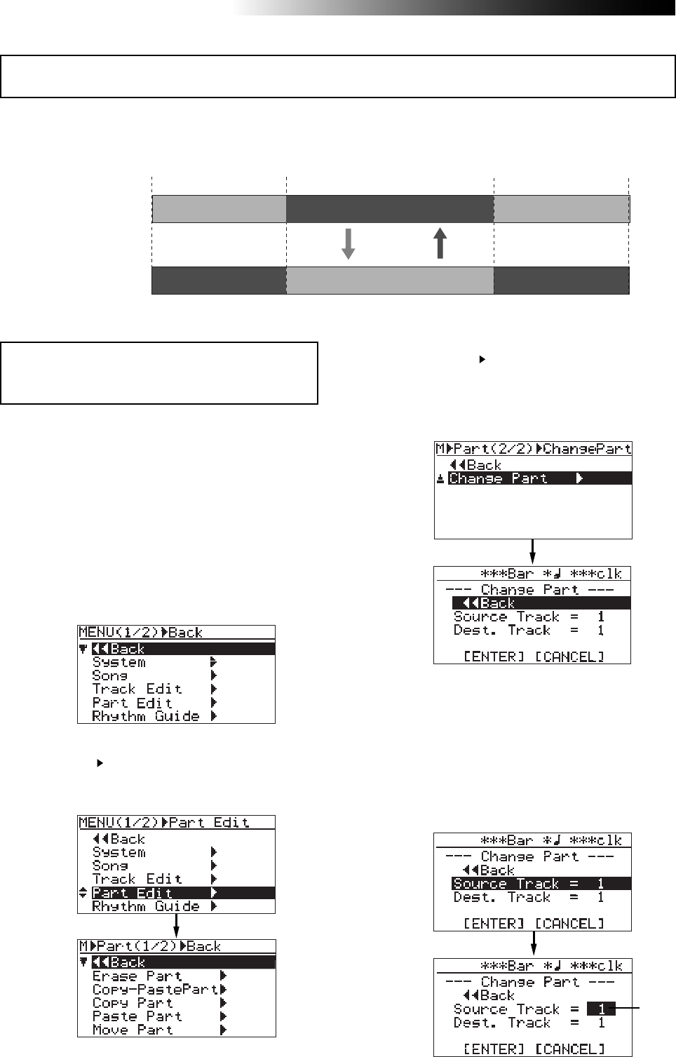
136
MR16 Owner’s Manual (Part editing)
5) Rotate the [MENU/ENTER] knob to select
"Change Part " in the second page, and press
the [MENU/ENTER] knob.
The display now shows the screen for
selecting the source track(s) and destination
track(s) of the exchange operation.
6) Rotate the [MENU/ENTER] knob to select
"Source Track=*", and press the [MENU/ENTER]
knob.
You can now select the exchange source track(s)
by rotating the [MENU/ENTER] knob.
The available options are:
• 1 through 8 (mono track)
• 1/2, 3/4, 5/6, 7/8, 9/10, 11/12, 13/14 and 15/16
(stereo tracks)
1) Load the song you want to edit.
2) Set the LOCATE A and LOCATE B points (see
page 53).
You can check the parts by playing back
between the LOCATE A and LOCATE B points
(see page 48).
3) While the recorder is stopped, press the
[MENU/ENTER] knob to enter the menu mode.
The display now shows the first page of the
menu selection screen.
You can exchange the parts between the desired tracks. The part exchange operation can be
made only within the current song.
<Note>:
You cannot exchange data of a song pro-
tected. Release the protection before exchanging
parts.
4) Rotate the [MENU/ENTER] knob to select
"Part Edit ", and press the [MENU/ENTER] knob.
The display now shows the part edit menu
screen.
Exchange the part(s)
Locate A point Locate B point
ABS ZERO REC END
You can exchange the
desired parts between
the desired track(s)
Flashing

137
MR16 Owner’s Manual (Part editing)
8) Rotate the [MENU/ENTER] knob to select the
destination track(s), and press the
[MENU/ENTER] knob.
The display shows the screen where
"Dest. Track = **" is highlighted.
<Note>:
If you are not satisfied with the re-
sult, press the [
UNDO/REDO
] key to undo the
operation (see page 127).
9) Rotate the [MENU/ENTER] knob to move the
cursor to "[ENTER]" on the screen, and press the
[MENU/ENTER] knob.
The display shows "Please Wait", immediately
followed by "Completed" when the MR16
completes the exchange operation.
If you want to cancel the exchange operation,
move the cursor to "[CANCEL]" on the screen,
and press the [MENU/ENTER] knob.
Flashing
Flashing
Flashing
7) Rotate the [MENU/ENTER] knob to select the
source track(s) to be exchanged, and press the
[MENU/ENTER] knob.
You can now select the exchange destination
track(s) by rotating the [MENU/ENTER] knob.
<Note>:
You cannot select the same track(s)
for the exchange source and destination.
You can select the same number of tracks as the
exchange destination track(s). For example, if you
select a mono track for the exchange source, you
can only select a mono track for exchange desti-
nation.
10) After pressing the [MENU/ENTER] knob, press
the [STOP] key to exit the MENU mode.

138
MR16 Owner’s Manual (Part editing)
139
MR16 Owner’s Manual (Other functions)
Other functions
This chapter describes the following functions which are important for
using the MR16.
(1) Hard disk formatting
(2) Peak hold time setting
(3) Pre-roll/post-roll time setting
(4) Beat resolution mode on/off
(5) Phantom power on/off
(6) AUX OUT 1/2 output mode setting
(7) Initializing the MR16
<Notes>
While a menu screen is shown, you can go up the menu screen level or
directly exit the menu mode by the following operations.
(1) Select “ Back” on a menu screen and press the [MENU/ENTER] knob.
The display returns to the previous (upper level) screen.
Repeating this operation finally exits the menu mode.
(2) Press the [REWIND] key.
The display returns to the previous (upper level) screen.
Repeating this operation finally exits the menu mode.
(3) Press the [STOP] key.
The menu mode exits and the display shows the home screen.
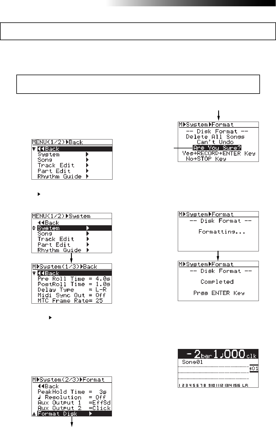
140
MR16 Owner’s Manual (Other functions)
You can reformat the MR16 internal hard disk by using the FAT32 file system.
By reformatting the hard disk, all existing song data on the hard disk is erased a new song
(Song01) is automatically created.
<Note>:
You cannot undo hard disk formatting. Therefore, before executing hard disk format-
ting, make sure that all song data on the hard disk is not necessary.
1) While the recorder is stopped, press the
[MENU/ENTER] knob to enter the menu mode.
The display now shows the first page of the
menu selection screen.
2) Rotate the [MENU/ENTER] knob to select
"System ", and press the [MENU/ENTER] knob.
The display now shows the first page of the
system menu screen.
3) Rotate the [MENU/ENTER] knob to select
"Disk Format " on the second page and press
the [MENU/ENTER] knob.
The display show the screen where "Are You
Sure?" flashes.
As this screen indicates, formatting the hard
disk deletes all songs on the disk and you
cannot undo disk formatting.
To stop formatting, press the [STOP] key to exit
the menu mode.
4) Press the [MENU/ENTER] knob while holding
down the [RECORD] key.
Formatting starts.
When formatting completes, “Completed” is
shown on the display and the MR16 stops disk
access.
5) Press the [MENU/ENTER] knob.
The MR16 exits the menu mode.
The display changes to the home screen for
Song01 (song name: Song01) which is
automatically created after formatting.
Hard disk formatting
Flashing
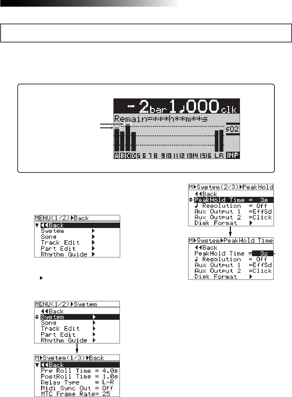
141
MR16 Owner’s Manual (Other functions)
The level meters shown on the display have the peak hold function.
When it is enabled, the meter peak value during recording is held for the specified time.
The default meter peak hold time is three seconds. You can disable the peak hold function or
change the peak hold time.
1) While the recorder is stopped, press the
[MENU/ENTER] knob to enter the menu mode.
The display now shows the first page of the
menu selection screen.
2) Rotate the [MENU/ENTER] knob to select
"System ", and press the [MENU/ENTER] knob.
The display now shows the first page of the
system menu screen.
3) Rotate the [MENU/ENTER] knob to select
"PeakHold Time=*.*s" on the second page and
press the [MENU/ENTER] knob.
The currently selected peak hold time (by
default, "3s") flashes.
You can now make the desired peak hold
setting.
4) Rotate the [MENU/ENTER] knob to select the
desired hold time, and press the [MENU/ENTER]
knob.
The peak hold setting is confirmed and the
display returns to the previous screen.
5) Press the [STOP] key to exit the menu mode.
The peak hold setting is effective to all songs.
You can select from "3s" (3 seconds, default),
"1s", "2s", "4s", "5s" and "Off".
When "Off" is selected, the peak hold function
is disabled (the peak value is not held).
Peak hold indication
By default, it is held for three
seconds.
Peak hold time setting
Flashing
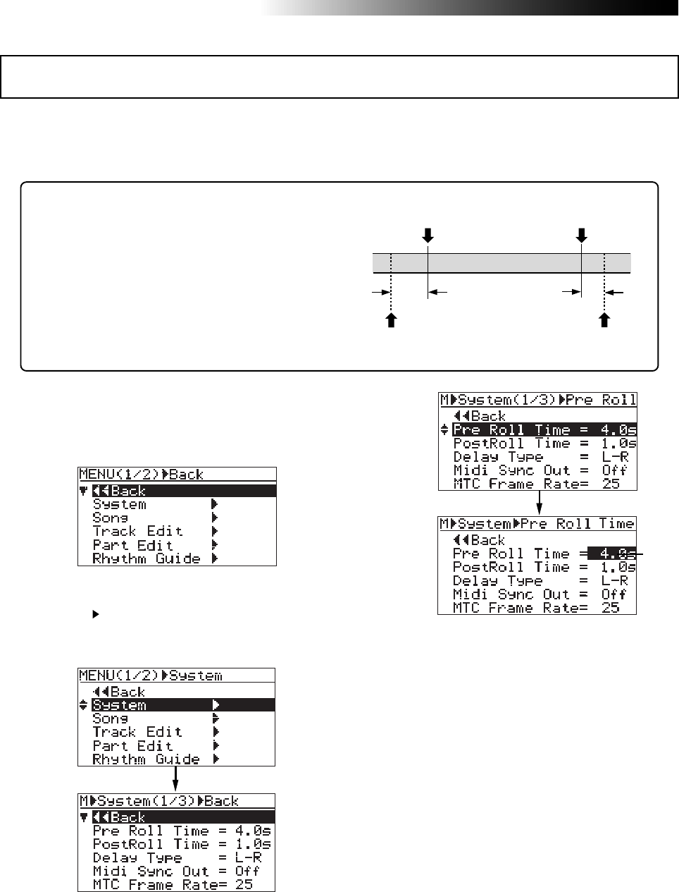
142
MR16 Owner’s Manual (Other functions)
As described earlier on page 51, when both the auto punch in/out and loop modes are active,
the pre-roll and post-roll are effective in the loop function. You can set the pre-roll and post-roll
time value by the following procedure.
When both the auto punch in/out and loop modes are ac-
tive, the loop starts from "the LOCATE A point minus the
pre-roll time" and ends by "the LOCATE B point plus the
post-roll time". The pre-roll time is initially set to four sec-
onds, while the post-roll time is set to one second.
In other words, with the default pre-roll and post-roll time
settings, when executing auto punch in/out, the MR16 starts
playback four seconds before the punch-in point, and ends
playback one second after the punch-out point.
1) While the recorder is stopped, press the
[MENU/ENTER] knob to enter the menu mode.
The display now shows the first page of the
menu selection screen.
2) Rotate the [MENU/ENTER] knob to select
"System ", and press the [MENU/ENTER] knob.
The display now shows the first page of the
system menu screen.
3) Rotate the [MENU/ENTER] knob to select
"Pre Roll Time=*.*s" and press the
[MENU/ENTER] knob.
The currently selected pre-roll time (by default,
"4.0s") flashes. You can now set the desired
pre-roll time.
You can select between "0.1s" and "10s" in 0.1
second steps.
4) Rotate the [MENU/ENTER] knob to select the
pre-roll hold time, and press the [MENU/ENTER]
knob.
The pre-roll time setting is confirmed and the
display returns to the previous screen.
To set the post-roll time, follow the procedure
below.
5) Rotate the [MENU/ENTER] knob to select
"Post Roll Time" and press the [MENU/ENTER]
knob.
The currently selected post-roll time (by
default, "1.0s") flashes. You can now set the
desired post-roll time.
You can select between "0.1s" and "10s" in 0.1
second steps.
6) Rotate the [MENU/ENTER] knob to select the
post-roll hold time, and press the [MENU/ENTER]
knob.
The post-roll time setting is confirmed and the
display returns to the previous screen.
7) Press the [STOP] key to exit the menu mode.
LOCATE A
Point LOCATE B
Point
4 sec. 1 sec.
LOOP START
point LOOP END
point
Pre-roll/post-roll time setting
Flashing
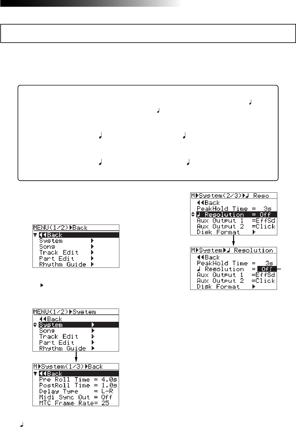
143
MR16 Owner’s Manual (Other functions)
While the time base is set to the bar/beat mode, if you set the "Beat resolution" item in the menu
to "On", the LOCATE A and B points are set in beat resolution.
When "Beat resolution" is set to "On", the clock digit in the bar/beat/clock value is automatically
rounded down or up, so that the clock digit is always "000".
Let's see an example when the time base is set to the bar/beat mode and the
"Beat resolution" is set to "On". If you set the LOCATE A point to "Bar 1/1 /clock
468" and the LOCATE B point to "Bar 12/ 4 /clock 485", the rounded values are
stored as below.
"Bar 1 / 1 / clock 468" -> "Bar 1 / 1 / clock 000"
(The clock value "468" is rounded down.)
"Bar 12 / 4 / clock 485" -> "Bar 13 / 1 / clock 000"
(The clock value "485" is rounded up.)
1) While the recorder is stopped, press the
[MENU/ENTER] knob to enter the menu mode.
The display now shows the first page of the
menu selection screen.
2) Rotate the [MENU/ENTER] knob to select
"System ", and press the [MENU/ENTER] knob.
The display now shows the first page of the
system menu screen.
3) Rotate the [MENU/ENTER] knob to select
" Resolution=**" on the second page and press
the [MENU/ENTER] knob.
The current option (by default, "Off") flashes.
You can now set the desired option.
4) Rotate the [MENU/ENTER] knob to select "On"
or "Off", and press the [MENU/ENTER] knob.
The selection is confirmed and the display
returns to the previous screen.
5) Press the [STOP] key to exit the menu mode.
Beat resolution mode on/off
Flashing
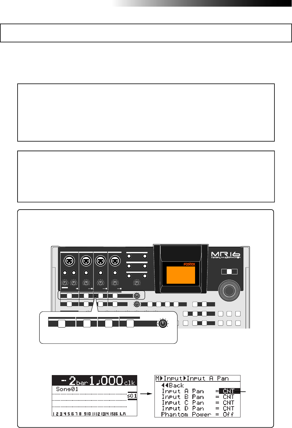
144
MR16 Owner’s Manual (Other functions)
The MR16 can supply phantom power (+48 V) to the XLR balanced connectors of [INPUT A]
through [INPUT D].
So you can connect condenser microphones which require phantom power.
You can turn on or off phantom power to the XLR connectors via the menu mode.
<Note>:
The phantom power can be supplied to the XLR balanced connectors of [
INPUT A
]
through [
INPUT D
]. Therefore, to connect a sound source which does not require the phan-
tom power, use any of the unbalanced phone input jacks on [
INPUT A
] through [
INPUT D
].
If any plug is inserted to the unbalanced phone input jack, the phantom power is not
supplied to the balanced XLR connector on the same channel.
The phantom power setting returns to "
Off
" (default) when you turn off the MR16 power.
<Notes on using phantom power>
• Confirm that the connected microphone needs +48 V phantom power.
• Turn on the phantom power after making microphone connection.
• Mute the outputs of the MR16 when turning on or off the phantom power or plugging/
unplugging the microphone.
<Tip>
You can directly access to the input menu screen by a long press of the desired [TO
STEREO BUSS ON/OFF] key.
Phantom power on/off
Flashing
PEAK
GUITAR
MIN
DISTORTION
MAX LINE MIC
TRIM
INSERT/GUITAR
UNBAL
BALBALBALBAL
INPUT A INPUT B INPUT C INPUT D
VOLUME
MIN MAX
PEAK
LINE
TRIM
MIC
UNBAL
POWER
UNBAL
MIC
TRIM
LINE
PEAK
UNBAL
MIC
TRIM
LINE
PEAK
R
L
100
SIMULATION SIMULATION
AMP
MIC
010
LR
010
LR RL
100 010
LR
RL
100
RL
100
010
LR
UNDO/REDO
STORE
BOUNCE
MASTERING
BRIGHT
15/16 > STEREO WAV FILE
NATURAL
POWERFUL
B / OUTA / INPLAY MODEAUTO PUNCH
LOCATE
EFFECT
DELAYPLATEHALLROOM BOUNCE MODE
CONTRAST
TIMEBASE SELECT
RHYTHM GUIDE DIRECT LOCATE
EFFECT SEND
PAN
INPUT EQ
TO STEREO BUSS LEVEL
MENU / ENTER
MIN MAX
MIN MAX
REVERB / DELAY TIME
LSTEREO OUT R
1AUX OUT 2
1PHONES 2
DYNAMIC BRIT STACK
INPUT A INPUT B INPUT C INPUT D
TO STEREO BUSS LEVEL
MIN MAX
INPUT A INPUT B INPUT C INPUT D
[TO STEREO BUSS] key
For example, a long press of the [TO STEREO BUSS ON/OFF] key of [INPUT A] directly
accesses to the screen shown below.
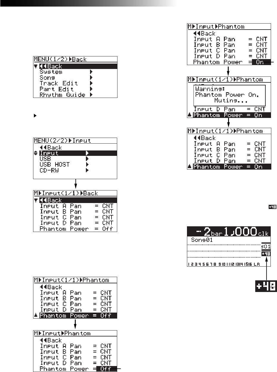
145
MR16 Owner’s Manual (Other functions)
4) Rotate the [MENU/ENTER] knob to select "On",
and press the [MENU/ENTER] knob.
The screen shows a warning message for few
seconds, and returns to the previous screen.
While the message is shown, all input
channels are muted. When the message is
dismissed, the mute is released.
If you select “Off” from “On”, a warning
message appears and all channels are muted.
5) After making "Phantom Power" setting, press the
[STOP] key to exit the menu mode.
The display returns to the home screen.
When "Phantom Power" is set to "On", " "
lights on the home screen, as below.
3) Rotate the [MENU/ENTER] knob to select
"Phantom Power=***", and press the
[MENU/ENTER] knob.
The current option (by default, "Off") flashes.
You can now set the desired option.
1) While the recorder is stopped, press the
[MENU/ENTER] knob to enter the menu mode.
The display now shows the first page of the
menu selection screen.
2) Rotate the [MENU/ENTER] knob to select
"Input " on the second page, and press the
[MENU/ENTER] knob.
The display now shows the input menu screen.
Flashing
Flashing
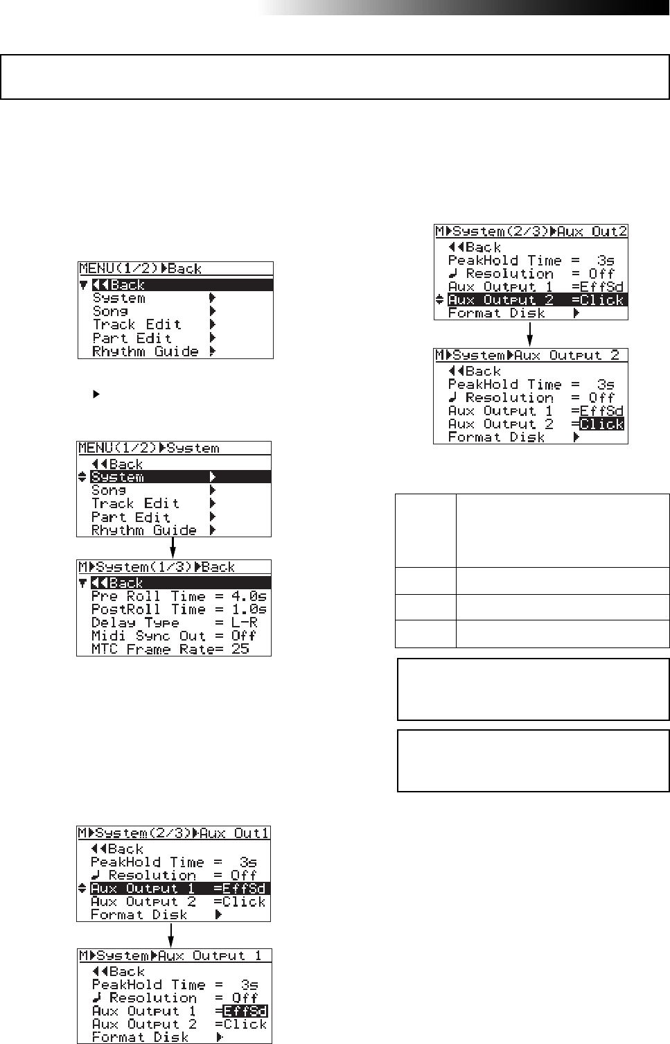
146
MR16 Owner’s Manual (Other functions)
You can individually select the output signal of AUX OUT 1 and AUX OUT 2 from among the track
signals, the effect send signal and the internal click. See "Application examples" on page 149 for
details about how to use AUX OUT.
AUX OUT 1/2 output mode setting
1) While the recorder is stopped, press the
[MENU/ENTER] knob to enter the menu mode.
The display now shows the first page of the
menu selection screen.
2) Rotate the [MENU/ENTER] knob to select
"System ", and press the [MENU/ENTER] knob.
The display now shows the first page of the
system menu screen.
3) Rotate the [MENU/ENTER] knob to select
"Aux Output 1" (or "Aux Output 2") on the
second page and press the [MENU/ENTER] knob.
The current option flashes. By default, "EffSd"
flashes for "Aux Output 1" while "Click" flashes
for "Aux Output 2".
You can now set the desired option.
• When "Aux Output 1" is selected
• When "Aux Output 2" is selected
You can select the output signal for each Aux
output from among the following options.
1
.
.
16
Mono track output
EffSd
Click
Effect send buss (see page 72)
Internal click (see page 89)
Off No output
4) Rotate the [MENU/ENTER] knob to select the
desired option, and press the [MENU/ENTER]
knob.
The selection is confirmed and the display
returns to the previous screen.
The display now shows the first page of the
system menu screen.
5) Press the [STOP] key to exit the menu mode.
<Note>:
The level of the [AUX OUT] signal is
fixed. There is no master level control for
the Aux output signal.
<Note>:
The level of the [AUX OUT] signal is
fixed. There is no master level control for
the Aux output signal.
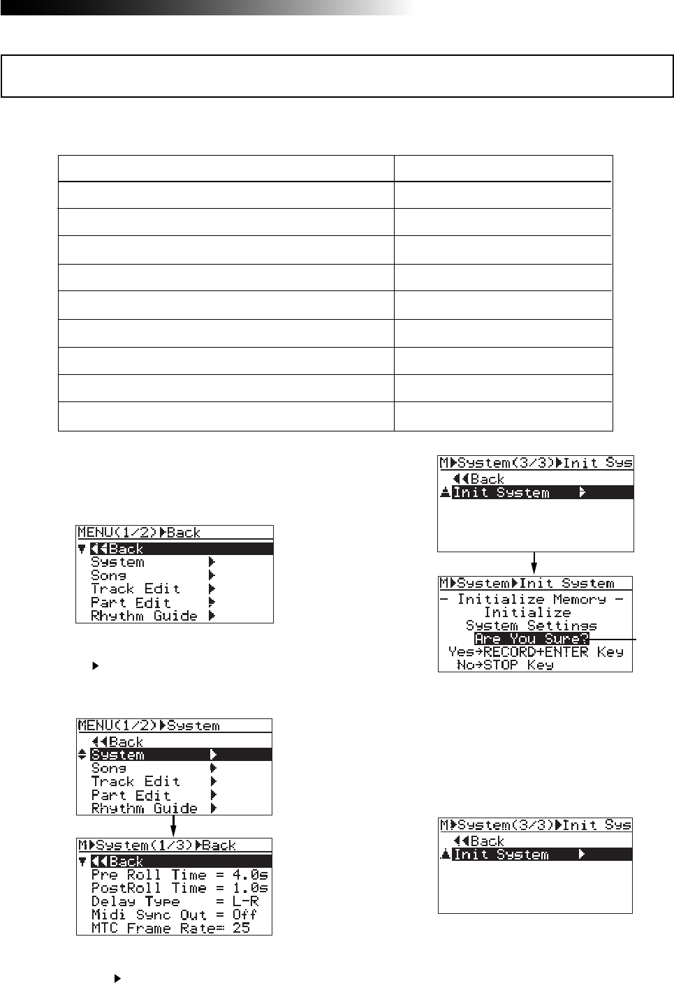
147
MR16 Owner’s Manual (Other functions)
By initializing the MR16, you can initialize all global menu settings common to all songs, as well
as the time base and display contrast level.
1) While the recorder is stopped, press the
[MENU/ENTER] knob to enter the menu mode.
The display now shows the first page of the
menu selection screen.
3) Rotate the [MENU/ENTER] knob to select
"Init System " on the second page, and press
the [MENU/ENTER] knob.
The display now shows the confirmation screen
for initializing.
4) Press the [MENU/ENTER] knob while holding
down the [RECORD] key.
The settings are immediately initialized.
The initialize is confirmed and the display
returns to the previous screen.
To cancel the initialization, press the [STOP]
key.
5) Press the [STOP] key to exit the menu mode.
Initialized item Default setting
Pre-roll time setting
Post-roll time setting
Delay type setting
MIDI sync out setting
MTC frame rate setting
Beat resolution mode setting
Peak hold time setting
Time base (shown when turning on the power)
Display contrast level
4 seconds
1 second
L-R (stereo) delay
Off
25 frames
Off
3 seconds
Bar/Beat
Factory present level
2) Rotate the [MENU/ENTER] knob to select
"System ", and press the [MENU/ENTER] knob.
The display now shows the first page of the
system menu screen.
Initializing the MR16
Flashing

148
MR16 Owner’s Manual (Other functions)

149
MR16 Owner’s Manual (Application examples)
Application examples
This chapter describes practical examples of using the MR16.
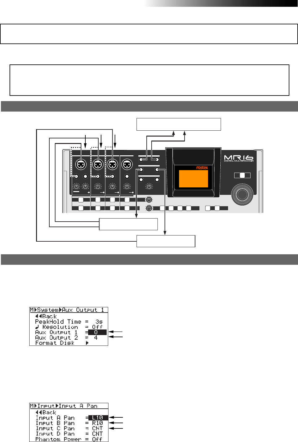
150
MR16 Owner’s Manual (Application examples)
This example uses the AUX OUT and TO STEREO BUSS functions. It is assumed that you want to
do the following.
(1) When mixing down tracks 1 through 16, you want to insert a delay effect to track 8 using an external
delay unit.
(2) You also want to insert an amplifier simulation effect to track 4 using an external amplifier simulator.
Application example 1 (Mixing)
Connection between the MR16 and external units
PEAK
GUITAR
MIN
DISTORTION
MAX LINE MIC
TRIM
INSERT/GUITAR
UNBAL
BALBALBALBAL
INPUT A INPUT B INPUT C INPUT D
VOLUME
MIN MAX
PEAK
LINE
TRIM
MIC
UNBAL POWER
UNBAL
MIC
TRIM
LINE
PEAK
UNBAL
MIC
TRIM
LINE
PEAK
BOUNCE
15/16 > STEREO WAV FILE
EFFECT
DELAYPLATEHALLROOM BOUNCE MODE
INPUT EQ
TO STEREO BUSS LEVEL
MENU / ENTER
MIN MAX
MIN MAX
REVERB / DELAY TIME
LSTEREO OUT R
1AUX OUT 2
1PHONES 2
INPUT A INPUT B INPUT C INPUT D
Master recorder
Delay unit
Amplifier simulator
Operation procedure
• Set the output source of AUX OUT 1 to track "8".
• Set the output source of AUX OUT 2 to track "4".
See page 146 for details about how to make
settings above.
• Set the panpot of INPUT A to "L10".
• Set the panpot of INPUT B to "R10".
• Set the panpot of INPUT C to "CNT".
See page 86 for details about how to make
settings above.
• Use the [To STEREO BUSS LEVEL] control to adjust
the effect (wet) sound level.
• Use the faders for tracks 1 through 16 to adjust the
track signal levels.
The output levels of AUX OUT 1 and AUX OUT 2
are fixed and not affected by the corresponding
track fader settings.
<Notes>
•
You can independently assign any one of tracks 1
through 16, the effect send and the internal click
to AUX OUT 1 and AUX OUT 2 (you cannot assign
more than one signal to each AUX OUT).
•
You can set pan for each of INPUT A through D at
the desired position between L10 and R10.
•
The mixing levels of INPUTs A through D are
collectively controlled by the [TO STEREO BUSS
LEVEL] control.
•
The balance among INPUTs A through D is
adjusted using the TRIM control for each input
channel or the output level control of each
external device. If you do not want to mix any of
the input channels, you can mute it.
•
The input channel which is assigned to a recorder
track for recording is not mixed.
• Turn on the [TO STEREO BUSS] keys for [INPUT A]
through [INPUT C].
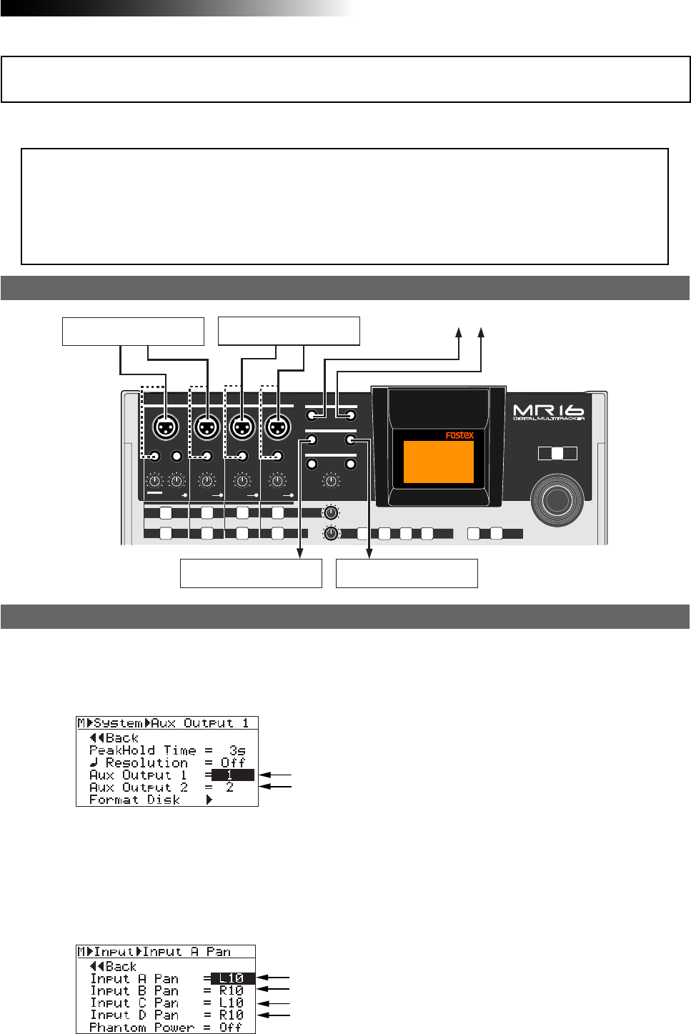
151
MR16 Owner’s Manual (Application examples)
PEAK
GUITAR
MIN
DISTORTION
MAX LINE MIC
TRIM
INSERT/GUITAR
UNBAL
BALBALBALBAL
INPUT A INPUT B INPUT C INPUT D
VOLUME
MIN MAX
PEAK
LINE
TRIM
MIC
UNBAL
POWER
UNBAL
MIC
TRIM
LINE
PEAK
UNBAL
MIC
TRIM
LINE
PEAK
BOUNCE
15/16 > STEREO WAV FILE
EFFECT
DELAYPLATEHALLROOM BOUNCE MODE
INPUT EQ
TO STEREO BUSS LEVEL
MENU / ENTER
MIN MAX
MIN MAX
REVERB / DELAY TIME
LSTEREO OUT R
1AUX OUT 2
1PHONES 2
INPUT A INPUT B INPUT C INPUT D
As example 1, this example also uses the AUX OUT and TO STEREO BUSS functions. It is assumed
that you want to do the following.
Application example 2 (Live)
Connection between the MR16 and external units
Operation procedure
(1) You want to use the MR16 in the live performance of a band, which uses synchronization between the
recorder tracks and keyboard live playing.
(2) The backing tracks (tracks 3 through 16) are played back by the MR16, while two keyboards are
played live.
(3) A click (recorded on tracks 1 and 2) is fed to the keyboard players.
• Set the output source of AUX OUT 1 to track "1".
• Set the output source of AUX OUT 2 to track "2".
See page 146 for details about how to make
settings above.
• Set the panpot of INPUT A to "L10".
• Set the panpot of INPUT B to "R10".
• Set the panpot of INPUT C to "L10".
• Set the panpot of INPUT D to "R10".
See page 86 for details about how to make
settings above.
• Use the [To STEREO BUSS LEVEL] control to adjust
the keyboard sound levels.
• Use the faders for tracks 3 through 16 to adjust the
track signal levels.
• Turn down the faders for tracks 1 and 2 (because
tracks 1 and 2 are click tracks).
Keyboard 1 Keyboard 2 To PA system
Headphone amplifier Headphone amplifier
<Notes>
•
You can independently assign any one of tracks 1
through 16, the effect send and the internal click
to AUX OUT 1 and AUX OUT 2 (you cannot assign
more than one signal to each AUX OUT).
•
You can set pan for each of INPUT A through D at
the desired position between L10 and R10.
•
The mixing levels of INPUTs A through D are
collectively controlled by the [TO STEREO BUSS
LEVEL] control.
•
The balance among INPUTs A through D is
adjusted using the TRIM control for each input
channel or the output level control of each
external device. If you do not want to mix any of
the input channels, you can mute it.
•
The input channel which is assigned to a recorder
track for recording is not mixed.
• Turn on the [TO STEREO BUSS] keys for [INPUT A]
through [INPUT D].

152
MR16 Owner’s Manual (Application examples)

153
MR16 Owner’s Manual (Troubleshooting)
Troubleshooting
If you encounter any problem while operating the MR16, check the fol-
lowing for the possible cause of the problem before contacting our ser-
vice station or dealer.
154
MR16 Owner’s Manual (Troubleshooting)
<Trouble 3>: The input level of the track to which I am going to record is too low.
• Is the [TRIM] control of the input to which the sound source is connected
adjusted appropriately?
To set the input level (= recording level) appropriately, use the [TRIM] control so
that the peak indicator does not light continuously.
<Trouble 1>: I cannot record the sound source connected to [INPUT B] to track 1.
• When recording a sound source to a mono track, you can only use the
[INPUT A] section.
Connect the source to [INPUT A].
<Trouble 2>: I cannot record the sound sources connected to [INPUT C] and [INPUT D]
to tracks 1 and 2.
• When recording two sound sources simultaneously, you must use
[INPUT A] and [INPUT B]. You cannot use [INPUT C] and [INPUT D].
Reconnect the sources to [INPUT A] and [INPUT B].
<Trouble 4>: I cannot hear the input signal via the headphones though the
[REC SELECT] key is active.
• Did you press the [RECORD] key to make the armed track in the input
monitor mode? Is the [PHONES VOL] control raised?
You cannot hear the input signal unless the assigned track is in the input monitor
mode by pressing the corresponding [REC SELECT] key to turn on the indicator.
Also, you cannot hear any signal if the [PHONES VOL] control is set to minimum.
Troubles for recording
<Trouble 5> : The meter shows very low level and the recording level is too low.
• Is the [TRIM] control for the input section the sound source is connected
adjusted appropriately?
Set the [TRIM] control just below the position where the [PEAK] indicator in the
[INPUT A] section lights at the loudest part.
155
MR16 Owner’s Manual (Troubleshooting)
<Trouble 8>: I cannot execute auto punch in/out.
• Is the auto punch in/out mode effective?
If it is not, press the [AUTO PUNCH] key to make the auto punch in/out function
active.
• Are the punch-in and punch-out points set correctly?
To check each point, press the [LOCATE A/IN] or [LOCATE B/OUT] key.
The recorder locates to the punch-in or punch-out point, while the screen shows
the appropriate time data.
If the punch-out point is earlier than the punch-in point, set these points
appropriately so that the punch-in point is earlier than the punch-out point.
<Trouble 9>: I cannot record audio data of a song onto an external digital recorder.
• Is the connection between the [DIGITAL OUT] connector on the MR16 and
the optical input connector of the digital recorder made correctly?
Check the connection, as well as the optical cable.
• Is the digital recorder set correctly for recording the signal fed to the
digital input?
See the manual of the digital recorder for details about the setting.
<Trouble 7>: During overdubbing, I cannot monitor the playback signal of the recorded
track.
• Is the track fader for the playback track raised?
During overdubbing, raise the faders for both the playback and recording tracks
appropriately. Otherwise, you cannot make overdubbing while listening to the
recorded track(s).
<Trouble 6>: The meter shows good level for recording, but no signal can be monitored
via headphones though the [PHONES VOL] control is raised.
• Are the track fader for the recording track and the [MASTER] fader raised?
Both of these faders, as well as the [PHONES VOL] control, have to be raised in
order to monitor the recording signal via headphones.
We recommend to raise both the track fader for the recording track and the
[MASTER] fader to the “ ” position.
• Is the recording track in the input monitor mode?
Make sure that the [RECORD] key flashes and " " is shown on the display.
If not, press the [RECORD] key to set the armed track to the input monitor mode.
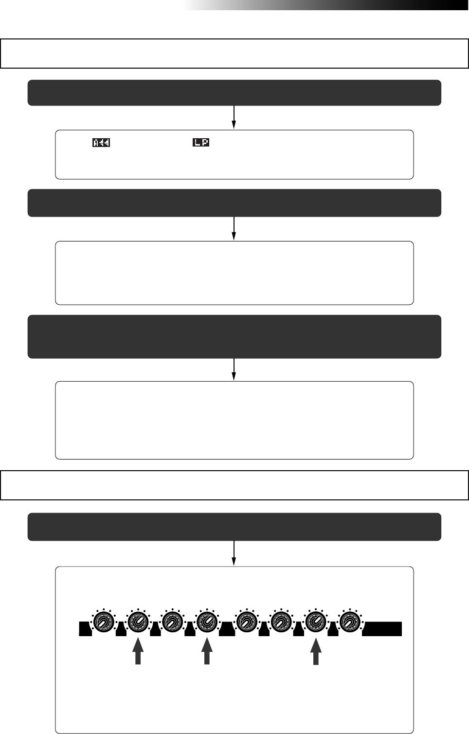
156
MR16 Owner’s Manual (Troubleshooting)
<Trouble 1>: During playback, the recorder suddenly executes locating.
• Is " (auto return)" or " (loop)" shown on the display?
If so, the play mode is set to the auto return or loop mode.
Press the [PLAY MODE] key until "Off" is selected.
<Trouble 2>: Cannot monitor the playback sound.
• Are the track fader(s) for the playback track(s) and the [MASTER] fader
brought up to the appropriate positions?
Raise the fader(s) for the track(s) you want to monitor, as well as the [MASTER]
fader. If you monitor via headphones, also raise the [PHONES VOL] control.
<Trouble 3>: I press the [PLAY] key while holding down the [STOP] key, but I cannot
execute loop playback.
• Are the LOCATE A and LOCATE B points set correctly?
By default, both of these points are set to the beginning of a song (i.e. "0m 00s
000ms" or "-2bar 1beat 00clk"). In this condition, you cannot execute loop play
back. Also, if the LOCATE B point is earlier than the LOCATE A point, you
cannot execute loop playback.
Troubles for playback
<Trouble 1>: I cannot apply the effects.
• Are the [EFFECT SEND] control for the track you want to apply the effect
and track fader raised appropriately?
Raise the [EFFECT SEND] control(s) for the track(s) (1 through 4) you want to
apply the effect to send signal(s) to the internal digital effects.
Also, make sure that the fader(s) for the track(s) you want to apply the effect
is(are) raised.
Troubles for effect
100010
010 100 010
100
100
010
EFFECT SEND
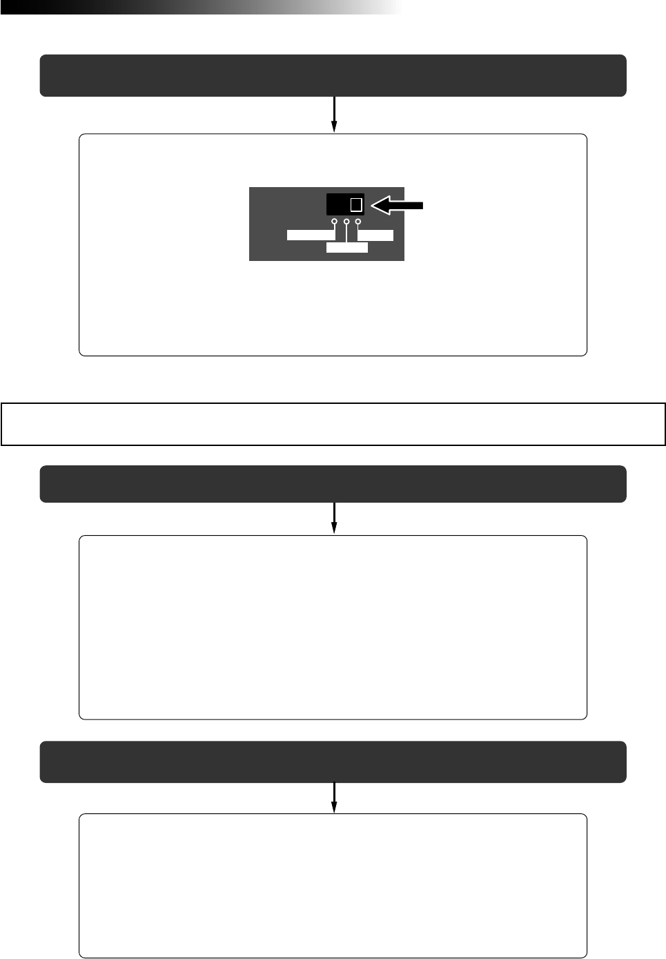
157
MR16 Owner’s Manual (Troubleshooting)
<Trouble 1>: Cannot export a WAV file to a personal computer.
• Is the USB cable connected correctly?
Check the connection, as well as the USB cable.
• Is the personal computer meets the requirement?
The MR16 can export a WAV file to a personal computer which runs on any of
the following OS systems.
Windows Me, 2000 or XP
Macintosh 0S X or higher
<Trouble 2>: I cannot apply the mic simulation effects.
• Is the [INPUT A SELECT] switch on the rear panel is set to "MIC/LINE"
position?
To apply the mic simulation effects to [INPUT A], the [INPUT A SELECT] switch
on the rear panel must be set to "MIC/LINE" position.
When you set the switch to any other position, you can use the amp simulation
effects for insert effects.
INPUT A SEL
MIC/LINE
GTR CLEAN
GTR DIST
<Trouble 2>: The MR16 drive icon is not shown on the personal computer screen.
• It may take some times for showing a removable drive depending on a
personal computer.
It may take some times for reading the drive data.
Wait for a while until the drive icon appears.
On a Windows machine, the MR16 is shown as "removable drive". On a Macintosh
machine, it is shown as "MR16".
Troubles for USB connection
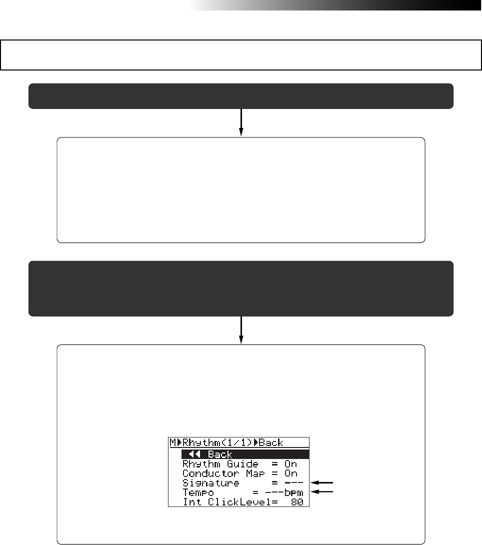
158
MR16 Owner’s Manual (Troubleshooting)
<Trouble 1>: I cannot hear the rhythm guide click.
• Is the [RHYTHM GUIDE] key is illuminated?
When the [RHYTHM GUIDE] key is not illuminated, the rhythm guide function is
not active and you cannot hear the rhythm guide click.
• Is the "Int Click level" item in the "Rhythm Guide" menu set correctly?
If the "Int Click level" item is set to "00" or a small value, you cannot hear the
rhythm guide click.
<Trouble 2> : I want to hear the rhythm guide click based on the "Signature" and "Tempo"
settings on the rhythm guide setting screen but the rhythm guide click
based on the conductor map is output.
• Is the "Conductor Map" setting on the rhythm guide setting screen set to
"On"?
As shown on the screen below, if "Conductor Map" on the rhythm guide setting
screen is set to "On", the rhythm guide click based on the conductor map is
output. In this condition, the "Signature" and "Tempo" fields on this screen
indicate "- - -" as below, showing that they are disabled.
Set "Conductor Map" to "Off" (see page 91).
Other troubles

159
MR16 Owner’s Manual (Specifications)
MR16 Specifications

160
MR16 Owner’s Manual (Specifications)
[Inputs/Outputs]
0dBu=0.775Vrms, 0dBV=1.0Vrms, Reference level: -12dBfs
Analog input [INPUT A - INPUT D]
Connectors : XLR-3-31 type (#2: hot balanced)
: 1/4-inch, phone type
Input level : -48dBu (MIC) to +4dBu (LINE)
Input impedance : 1.5kΩ or more
: 400kΩ or more (When the INPUT
A SEL switch is set to “GTR”.)
Phantom power : P48V (Phantom power ON/OFF is
selected in the “Input” menu of the
MENU mode.)
Insert [INSERT (input A only)]
Connector : 1/4-inch, TRS phone type
(Tip: output, Ring: input)
Norminal output level : -10dBV
Load impedance : 10kΩ or more
Norminal input level : -10dBV
Input impedance : 10kΩ or more
Stereo analog output [STEREO OUT (L, R)]
Connectors : 1/4-inch, phone type
Norminal output level : -10dBV (unbalanced)
Load impedance : 10kΩ or more
Auxiliary output [AUX OUT 1, 2]
Connectors : 1/4-inch, phone type
Norminal output level : -10dBV (unbalanced)
Load impedance : 10kΩ or more
Headphones output [PHONES 1, 2]
Connectors : 1/4-inch, stereo phone type
Max. output power : 50mW or more (at 32Ω load)
Load impedance : 16Ω or more
MIDI output [MIDI OUT]
Connector : DIN 5-pin
Format : Conformed to the MIDI standard
Digital output [DIGITAL OUT]
Connector : Toslink optical type
Format : IEC 60958 (S/P DIF)
Footswitch [FOOT SW]
Connector : 1/4-inch, phone type
Level : TTL level
USB (USB 2.0 HI-SPEED)
Connector : B type (standard)
USB HOST (USB 1.1)
Connector : A type (standard)
1
3
2
[Pin assignment of XLR connectors]
1 GND
2 HOT
3 COLD
[Pin assignment of USB port]
1 VBUS
2D-
3D+
[Pin assignment of USB HOST port]
4 GND
1
2
34
1234
1 VBUS
2D-
3D+
4 GND
Specifications
[General]
Weight (net) : Approx. 3.3 kg
: Approx. 3.5 kg (CD-R/RW drive
built-in model)
Dimensions : 400 (W) x 265 (D) x 85 (H ) mm
Power supply : 120VAC 50/60Hz
: 230VAC 50/60Hz
: 240VAC 50/60Hz
Power consumption : 14 W
: 20 W (CD-R/RW drive built-in model)
Supplied Accessaries : Power cord, Owner’s Manual
* Changes in specifications and features may be made
without notice or obligation.
[Record / playback]
Recording medium : 3.5-inch hard disk drive
Sampling frequencies: 44.1kHz
Quantization : 16-bits, linear (non expanded)
File format : FAT32
Audio recording type : Conformed to AES-31
Audio file type : BWF
The number of tracks : 16
* the number of simultaneously recordable tracks: 4
ADC/DAC : 24-bits, delta-sigma
Frequency response : 20Hz to 20kHz
Dynamic range : 93dB or more (TYPICAL)
Total harmonic distortion : 0.01% or less (TYPICAL)
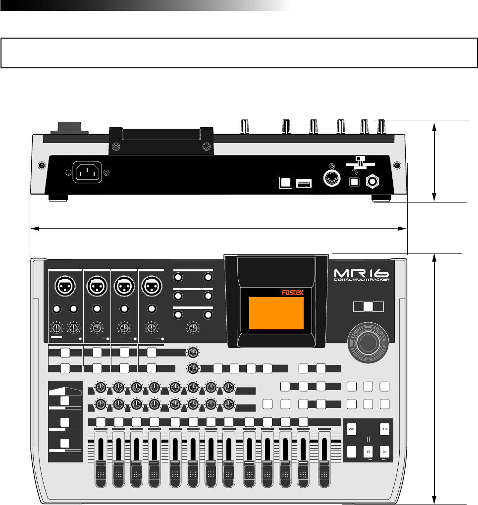
161
MR16 Owner’s Manual (Specifications)
Physical dimensions
PEAK
GUITAR
MIN
DISTORTION
MAX LINE MIC
TRIM
INSERT/GUITAR
UNBAL
BALBALBALBAL
INPUT A INPUT B INPUT C INPUT D
VOLUME
MIN MAX
PEAK
LINE
TRIM
MIC
UNBAL
POWER
UNBAL
MIC
TRIM
LINE
PEAK
UNBAL
MIC
TRIM
LINE
PEAK
MAX
MIN
1
R
L
100
SIMULATION SIMULATION
AMP
MIC
010
LR
010
LR
23
RL
100
4 8
010
LR
7
6
RL
100
RL
100
010
LR
5
MAX
MIN
MASTER
REC SELECT
RECORD STOP PLAY
REWIND F FWD
UNDO/REDO
STORE
LOCATE REC END
LOCATE ABS ZERO
A-B PLAY
BOUNCE
MASTERING
BRIGHT
15/16 > STEREO WAV FILE
NATURAL
POWERFUL
B / OUTA / INPLAY MODEAUTO PUNCH
LOCATE
EFFECT
DELAYPLATEHALLROOM BOUNCE MODE
CONTRAST
TIMEBASE SELECT
RHYTHM GUIDE DIRECT LOCATE
EFFECT SEND
PAN
INPUT EQ
TO STEREO BUSS LEVEL
9/10 11/12 13/14 15/16
ABC1 DEF2 GHI3 JKL4 MNO5 YZ9PQR6 +-_0STU7 VWX8 DELETE
MENU / ENTER
MIN MAX
MIN MAX
REVERB / DELAY TIME
LSTEREO OUT R
1AUX OUT 2
1PHONES 2
DYNAMIC BRIT STACK
CONDENSER US METAL
TUBE 60'S COMBO
INPUT A INPUT B INPUT C INPUT D
USB USB HOST MIDI OUT DIGITAL OUT FOOT SW
INPUT A SEL
GTR CLEAN MIC/LINE
GTR DIST
400
85
265

162
MR16 Owner’s Manual (Specifications)
When using the normal mode
Block diagram
DISTORTION
CLEAN
INPUT A
INPUT B
INPUT C
INPUT D
TRIM
TRIM
TRIM
TRIM
A/D
A/D
A/D
BAL
BAL
BAL
BAL
IN15
IN16
OUT15
OUT16
IN13
IN14
OUT13
OUT14
IN4 OUT4
IN3 OUT3
IN2 OUT2
IN1 OUT1
RECORDER
TRK 1 FADER
TRK 2 FADER
TRK 3 FADER
TRK 4 FADER
TRK 13/14 FADER
TRK 15/16 FADER
TRK 4 EFF
TRK 3 EFF
TRK 2 EFF
TRK 1 EFF
TRK 1 PAN
TRK 2 PAN
TRK 3 PAN
TRK 4 PAN
EFF
MASTER
FADER MASTERING FX ST OUT L
ST OUT R
IN11
IN12
OUT11
OUT12
IN9
IN10
OUT9
OUT10 TRK 9/10 FADER
TRK 11/12 FADER
IN8 OUT8
IN7 OUT7
IN6 OUT6
IN5 OUT5
TRK 5 FADER
TRK 6 FADER
TRK 7 FADER
TRK 8 FADER
TRK 8 EFF
TRK 7 EFF
TRK 6 EFF
TRK 5 EFF
TRK 5 PAN
TRK 6 PAN
TRK 7 PAN
TRK 8 PAN
SIMULATION
FX
A/D INPUT
EQ
INPUT
EQ
INPUT
EQ
INPUT
EQ
AUX 1/2 SEL
AUX 1/2 SEL
AUX 1/2 SEL
AUX 1/2 SEL
AUX 1/2 SEL
AUX 1/2 SEL
AUX 1/2 SEL
AUX 1/2 SEL
AUX 1/2 SEL
AUX 1/2 SEL
AUX 1/2 SEL
AUX 1/2 SEL AUX 1/2 SEL
PHONE 1
PHONE 2
REVERB / DELAY
REVERB / DELAY TIME
REC
SELECT
PAN
PAN
PAN
PAN
INPUT A
INPUT B
INPUT C
INPUT D
TO STEREO BUSS
TO STEREO BUSS
LR
AUX 1/2 SEL AUX OUT 1
AUX OUT 2
TRK1-8
9/10-15/16
MST
CLK
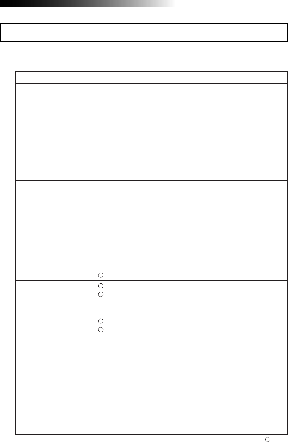
163
MR16 Owner’s Manual (Specifications)
<Digital multitracker>
Transmitted Recognized Remarks
Function............
Basic Default
Channel Changed
Default
Message
Altered
Mode
Note
Number: True Voice
Velocity Note ON
Note OFF
After Key's
Touch Channel's
Pitch Bend
Control
Change
Program
Change: True #
System Exclusive
: Quarter Frame
: Song Position
: Song Select
: Tune
Common
System
Real Time
: Clock
: Commands
: Local ON/OFF
: All Notes OFF
: Active Sense
: Reset
Aux.
Message
Notes
X
X
X
X
X
X
X
X
X
X
X
X
X
X
X
X
*****************************
XX
XX
X
X
X
X
X
X
X
X
X
*****************************
X
X
X
X
*****************************
X
X
X
X
X
X
X
rem.1 : MTC
rem. 2 : START, STOP, CONTINUE
Mode 1: OMNI ON, POLY Mode 2: OMNI ON, MONO
Mode 3: OMNI OFF, POLY Mode 4: OMNI OFF, MONO
: Yes
X : No
rem. 2
X
X
X
X
rem. 1
Date:
Version: V1.00
Model MR16
MIDI implementation chart

164
MR16 Owner’s Manual (Specifications)
<A>
Amp simulation ...............................................................68
Auto return ......................................................................49
Auto play .........................................................................49
ABS time .........................................................................15
Archiving a song ...........................................................111
Analog mixdown .............................................................44
Auxiliary output ...............................................150 and 151
Audio CD .........................................................................17
<B>
Bounce ............................................................................75
Bar/Beat ......................................................15, 27 and 143
Beginning a song ..............................................15 and 52
Bar offset .........................................................................95
<C>
Cueing .............................................................................48
Clipboard ......................................................................131
Click level ........................................................................91
Clock .............................................................................102
Contrast ..........................................................................27
Copy .................................................121, 129 through 133
Copyrights .......................................................................10
Conductor map ...............................................................92
Changing track ..............................................................125
Character entry key ..........................................34 and 115
Creating a song ...............................................................33
<D>
Delay ...............................................................................70
Distortion ............................................................35 and 68
Display ............................................................................26
Demo song ......................................................................31
Digital mixdown ...............................................................45
Direct locate ....................................................................55
Delete song ...................................................................116
Damage ..........................................................................10
<E>
Effector ............................................................................65
Effect send ......................................................................72
Erasing track .................................................................120
Erase part ......................................................................128
Event ..........................................................93 through 98
Exchange the track .......................................................125
Exchange the parts .......................................................136
<F>
Format ...........................................................................140
Foot switch ......................................................................61
<G>
Gain .......................................................16, 37 through 42
<H>
Hard disk .................................................110, 111 and 140
Hidden file .........................................................95 and 116
<I>
Internal CD-R/RW drive ..................................................25
Insert effect ......................................................................68
Input A select switch .........................................35 and 68
Input monitor ........................................15, 37 through 42
Insert ...............................................................................69
Input ................................................................................35
Input EQ ..........................................................................66
Initialize .........................................................................147
<L>
Loop ................................................................................49
Locate .............................................................................52
Locate accuracy ..............................................................56
<M>
Master recorder ...........................................43 through 45
Mastering effect ..............................................................73
Mic simulation .................................................................68
MIDI .................................................................................99
MIDI implementation chart ...........................................163
Mixdown ......................................................43 through 45
Move ...............................................................123 and 134
MENU mode ...................................................................28
<O>
Overdubbing ...................................................................39
Offset ...............................................................................95
Optical cable ......................................................24 and 45
<P>
Playback .........................................32, 38, 40, 42 and 47
Power supply ..................................................................30
Power switch ...................................................................30
Personal computer .......................................................107
Part ................................................................................127
Punch in/out ....................................................................59
Punch in/out points .........................................................62
Play mode .......................................................................49
Pre roll ...............................................................51 and 142
Peak LED ........................................................................16
Peak hold ......................................................................141
Phantom power ............................................................144
Protect .............................................................110 and 117
Paste .......................................................121, 129 and 131
Post roll .............................................................51 and 142
Preview ...........................................................................58
<Q>
Quantization ..............................................................160
<R>
Recording ....................................................37 through 45
Recording level ...........................................37 through 45
Recording track ...............................................................36
Recording method ..........................................................13
Reverb ............................................................................70
Redo ...................................................38, 40, 42, 119, 127
Remain ...........................................14, 26, 38, 40 and 42
Index

165
MR16 Owner’s Manual (Specifications)
Rehearsal ....................................................63, 79 and 82
Repro monitor .................................................................15
Resolution .....................................................................143
REC END ..........................................................13 and 52
Rhythm guide ..................................................................89
<S>
Signature .....................................................90 through 94
Simulation .......................................................................68
Sequencer ......................................................................99
Signature map ................................................................92
Standby mode .................................................................30
Song .................................................................14 and 113
Select a song .................................................................114
Song name ........................................................33 and 115
Synchronization ............................................................99
Song protect ..................................................................117
S/P DIF ............................................................................45
<T>
Track ..............................................................................36
Trouble shooting ...........................................................153
Trim .......................................................16, 37 through 42
Track fader ..................................................37 through 42
Time base ..........................................................15 and 27
Tempo map .....................................................................96
<U>
Undo .............................................38, 40, 42, 119 and 127
USB ...............................................................................107
USB HOST ...................................Supplementary manual
<W>
WAV file .............................................................14 and 103
WAV file conversion ......................................................104
WAV manager ...................................................17 and 111
Warning ...........................................................................28
<Y>
Y cable ...............................................................20 and 69

166
MR16 Owner’s Manual (Specifications)
Declaration of EC Directive
This equipment is compatible with the EMC Directive (89/336/EEC) - Directive on approximation of member
nation's ordinance concerning the electromagnetic compatibility and with the Low Voltage Directive (73/23/EEC)
- Directive on approximation of member nation's ordinance concerning electric equipment designed to be used
within the specified voltage range.
The Affect of Immunity on This Equipment
FOSTEX DISTRIBUTORS LIST IN EUROPE
* Including non-EU countries (as of January, 2005)
<ITALY>
NAME: Proel S. p. A.
ADD: Zona Via Alla Ruenia, 37/43 64027 -
Sant'Omero (Teramo), Italy
TEL: (+39) 0861-81241, FAX: (+39) 0861-887862
<THE NETHERLANDS>
NAME: IEMKE ROOS AUDIO B. V.
ADD: Kuiperbergweg 20, 1101 AG Amsterdam, The
Netherlands
TEL: (+31) 20-697-2121, FAX: (+31) 20-697-4201
<NORWAY>
NAME: Siv. Ing. Benum AS
ADD: P.O. Box 145, Vinderen, 0319 Oslo, Norway
TEL: (+47) 2213 9900, FAX: (+47) 2214 8529
<PORTUGAL>
NAME: Caius - Tecnologias Audio e Musica, Lda.
ADD: Praca do Bom Sucesso, No 61 Bom Sucesso
Trade Center, Escritorio 701/702, 4150-1460 Porto,
Portugal
TEL: (+351) 22-608-06-10, FAX: (+351) 22-608-06-29
<SPAIN>
NAME: Letusa S. A.
ADD: C/Laguna 10, 28923 Alcorcon, Madrid, Spain
TEL: (+34) 91-4862800, 91-4470898
FAX: (+34) 91-6414597
<SWEDEN>
NAME: Sennheiser AB
ADD: John Ericssonsgatan 10, P.O. Box 22035, SE-104
22 Stockholm, Sweden
TEL: (+46) 8 566 16400, FAX: (+46) 8 566 16490
<SWITZERLAND>
NAME: Audio Bauer Pro AG
ADD: Bernerstrasse-Nord 182, CH-8064 Zurich,
Switzerland
TEL: (+41) 1-4323230, FAX: (+41) 1-4326558
<UK>
NAME: SCV London
ADD: 40 Chigwell Lane, Oakwood Hill Industrial
Estate, Loughton, Essex IG10 3NY U. K.
TEL: (+44) 20-8418-0778, FAX: (+44) 20-8418-0624
<AUSTRIA>
NAME: ATEC Audio-u. Videogeraete
VertriebsgesmbH.
ADD: Im Winkel 5, A-2325 Velm, Austria
TEL: (+43) 2234-74004, FAX: (+43) 2234-74074
<BELGIUM>
NAME: General Audio
ADD: Raymond Pelgrimslaan 101, B-1702 Groot-
Bijgaarden, Belgium
TEL: (+32) 2-4630650, FAX: (+32) 2-4661500
<DENMARK>
NAME: SC Sound ApS
ADD: Malervej 2, DK-2630 Taastrup, Denmark
TEL: (+45) 4399-8877, FAX: (+45) 4399-8077
<FINLAND>
NAME: Noretron Oy Audio
ADD: P. O. Box 22, FIN-02631 Espoo, Finland
TEL: (+358) 9-5259330, FAX: (+358) 9-52593352
<FRANCE>
NAME: Sennheiser France
ADD: 128 bis, avenue Jean-Jaures, 94851 Ivry-sur-
Seine Cedex, France
TEL: (+33) 1 4987 0300, FAX: (+33) 1 4987 0324
<GERMANY>
NAME: Mega Audio GmbH
ADD: Stromberger Str. 32, D-55411 Bingen, Germany
TEL: (+49) 6721-94330, FAX: (+49) 6721-32046
<GREECE>
NAME: Bon Studio S. A.
ADD: 6 Zaimi Street, Exarchia, 106.83 Athens, Greece
TEL: (+30) 210-3809-605, 606, 607, 608
FAX: (+30) 210-3845-755, 210-3827-868
<ICELAND>
NAME: I. D. elrf. electronic Ltd.
ADD: ARMULA 38 108 REYKJAVIK, ICELAND
TEL: (+354) 588 5010, FAX: (+354) 588 5011
In the electrical fast transient/burst requirements, surge, conducted disturbances by radio-frequency fields,
power frequency magnetic field, radiate electromagnetic field requirements and static electricity discharging
environment, this could be affected by generation of noise in some cases.
The affect of the European Specification EN61000-6-1 (coexistence of electromagnetic waves - common
immunity specification) on this equipment are as shown below.

167
MR16 Owner’s Manual (Specifications)
FOR THE US CUSTOMERS ONLY
FOSTEX AMERICA LIMITED WARRANTY
The following statement defines specific legal rights. You may also have additional rights de-
pending on the state in which the Fostex product was purchased.
WARRANTY PROTECTION
All Fostex parts are warranted for one (1) year from the date of original purchase, except for
recording media, such as hard disc drives and compact flash cards, heads, lamps and fuses,
which are warranted, for one hundred-eighty (180) days. Fostex America will repair and / or
replace parts during the term of this warranty. Labor costs are also covered by Fostex America
for one (1) year from the date of original purchase. Except as specified below, this warranty
covers all defects in material and workmanship in this product.
The following are not covered by this warranty:
1. Batteries.
2. Damage to any product that has been altered.
3. Damage to any product on which the original serial number has been defaced, modified or
removed.
4. Damage to or deterioration of the external cabinet.
5. Damage occurring during shipment of the product. (NOTE: Shipping claims must be
presented to the carrier.)
6. Damage resulting from accident, misuse, abuse or neglect.
7. Damage resulting from failure to perform routine maintenance and / or calibration
procedures.
8. Damage resulting from failure to follow instruction in the owner's manual.
9. Damage resulting from repair or attempted repair or by someone other than a Fostex
America Service technician or a technician at an authorized Fostex America service station.
10. Damage resulting from causes other than product defects, including lack of technical skill,
competence or experience on the part of the user.
11. External appearance items such as cosmetic parts, knobs, liquid crystal displays, buttons,
etc.
12. Replacements or repairs necessitated by loss or damages resulting from any cause beyond
the control of Fostex America.
13. Damage resulting from misuse or abuse on rental units.
NOTE: FOSTEX AMERICA IS NOT RESPONSIBLE FOR DATA LOST OR DAMAGED
DURING OPERATION OF THIS PRODUCT.
CALIBRATION AND MAINTENANCE PROCEDURES ARE NOT COVERED BY
THIS WARRANTY.
Fostex America reserves the right to inspect all products submitted pursuant to this warranty.
If such an inspection shows reasonable cause to believe that any of the above exclusions to the
above warranty are applicable, then Fostex America or the authorized service station will charge
prevailing service rates and parts, costs for any repairs.

168
MR16 Owner’s Manual (Specifications)
FOSTEX AMERICA LIMITED WARRANTY
To claim all warranty service, first access www.fostex.com to receive service authorization (RMA
number). Then present the authorization together with the bill of sale, which shows the date of
original purchase to Fostex America. This warranty is not transferable.
SHIPPING
If this product needs service, you must take it, or package it carefully, using ample packaging
materials to prevent damage during shipment and mail it to the distributor from whom you
have purchased this product, postage pre-paid and insured.
NOTE: Fostex America will not assume responsibility for damages or losses occurred in transit,
but will reasonably assist the sender in processing any claims whenever possible (such as sub-
mitting statements to the carriers when applicable).
Any collect or C.O.D. shipments will be refused. In order to obtain warranty repairs, you must
include the following:
1. Date proof of original purchase (copy pf bill of sale or charge slip).
2. A note describing the problem with sufficient particularity to allow Fostex America to
inspect or adjust the problem.
3. All accessory items appurtenant to that problem.
LIMITATIONS OF INPLIED WARRANTIES
AND EXCLUSIONS OF CERTAIN DAMAGES
Unless considered unenforceable or unlawful under applicable law:
A. All implied warranties ? including warranties of merchantability and fitness for a
particular purpose ? are limited in duration to term of this warranty and to the express
coverage of this warranty;
B. Fostex America's liability for any defect product is expressly limited to repair or
replacement of the product, at the sole discretion and / or option of Fostex America.
Fostex America shall not under any circumstances be liable for:
1. Damaged based on inconvenience, loss of use of the product, loss of time,
interrupted operation or commercial loss, OR;
2. Any damages, whether incidental, consequential or otherwise, except damages
which may not be excluded by under applicable law.
C. Fostex America makes no other warranties, express or implied, above and / or beyond the
representations made herein.
WARRANTY APPLIES ONLY TO THOSE PRODUCTS SOLD AND
DISTRIBUTED BY FOSTEX AMERICA
Service Department
FOSTEX AMERICA
13701 Cimarron Avenue Gardena, CA 90249
TEL: (310)-329-2960 FAX: (310)-329-1230
www.fostex.com

FOSTEX CO.
3-2-35, Musashino, Akishima-shi, Tokyo, Japan, 196-0021
FOSTEX AMERICA
13701 Cimarron Avenue Gardena, CA 90249 U.S.A.
© PRINTED IN CHINA JANUARY 2007 8588 088 000
452187
