Fostex Vf80 Users Manual 01Cover_page (80E)
VF80 to the manual a5212862-ddad-4de8-a004-d44570433bef
2015-02-02
: Fostex Fostex-Vf80-Users-Manual-428075 fostex-vf80-users-manual-428075 fostex pdf
Open the PDF directly: View PDF ![]() .
.
Page Count: 144 [warning: Documents this large are best viewed by clicking the View PDF Link!]
Digital Multitracker
Owner’s Manual
8588 011 000
(356698)
DIGITAL MULTITRACKER
LOCATE ABS 0
LOCATE REC END
SEL
TIMEBASE
CURSOR
PHANTOM
ACCESS
PEAK
CH ON/OFF
LR
GUITAR
GUITAR
LINE MIC LINE MIC MIN MAX
MASTERING TRAINING
EFFECTEQPAN
SCENE SEQ.SCENE
TRACK
UNDO
SETUP
PUNCH
AUTO LOOP PITCH SCRUB
VARI
F FWDREWINDPLAYSTOPRECORD
EXIT
ENTER
TRIMTRIM
WAVE FORM
MIX PARAMETER
PGM FADER MAP
ON/OFF
2TRK MODE
F1 F2 F3 SHIFT
EDIT EDIT EDIT MARK DELETE
LOCATE
FOOT SW
ST OUT
PHONES
INPUT A
BOUNCE
INPUT B
+6
-10
-20
-40
-
∞
-30
0
+6
-10
-20
-40
-
∞
-30
0
+6
-10
-20
-40
-
∞
-30
0
+6
-10
-20
-40
-
∞
-30
0
+6
-10
-20
-40
-
∞
-30
0
+6
-10
-20
-40
-
∞
-30
0
+6
-10
-20
-40
-
∞
-30
0
+6
-10
-20
-40
-
∞
-30
0
PEAK
CH ON/OFF
2345 6 7/8 2TRK1 MASTER
TRACK STATUS / TRACK SEL
TRACK STATUS
RED REC GREEN PLAY OFF MUTE STATUS
/SEL
EJECT
/YES
/NO
SHUTTLE
JOG
UNBAL UNBAL
BAL
BAL
F1 F2 F3
EDIT
/REDO
REC EFF
2
Safety Instructions/Precautions
CAUTION: TO REDUCE THE RISK OF ELECTRIC SHOCK,
DO NOT REMOVE COVER (OR BACK).
NO USER - SERVICEABLE PARTS INSIDE.
REFER SERVICING TO QUALIFIED SERVICE PERSONNEL.
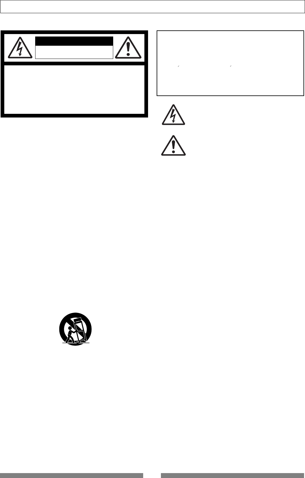
CAUTION
RISK OF ELECTRIC SHOCK
DO NOT OPEN
9. Heat - The appliance should be situated away from heat sources
such as radiators, heat registers, stoves, or other appliances
(including amplifiers) that produce heat.
10. Power Sources - The appliance should be connected to a power
supply only of the type described in the operating instructions or
as marked on the appliance.
11. Grounding or Polarization - The precautions that should be taken
so that the grounding or polarization means of an appliance is
not defeated.
12. Power Cord Protection - Power supply cords should be routed
so that they are not likely to be walked on or pinched by items
placed upon or against them, paying particular attention to cords
at plugs, convenience receptacles, and the point where they
exit from the appliance.
13. Cleaning - The appliance should be cleaned only as
recommended by the manufacturer.
14. Nonuse Periods - The power cord of the appliance should be
unplugged from the outlet when left unused for a long period of
time.
15. Object and Liquid Entry - Care should be taken so that objects
do not fall and liquids are not spilled into the enclosure through
openings.
16. Damage Requiring Service - The appliance should be serviced
by qualified service personnel when:
A. The power supply cord or the plug has been damaged; or
B. Objects have fallen, or liquid has been spilled into the appliance; or
C. The appliance has been exposed to rain; or
D. The appliance does not appear to operate normally or
exhibits a marked change in performance; or
E. The appliance has been dropped, or the enclosure damaged.
17. Servicing - The user should not attempt to service the appliance
beyond that described in the operating instructions.
All other servicing should be referred to qualified service
personnel.
The lightning flash with arrowhead symbol, within an equilateral
triangle, is intended to alert the user to the presence of
uninsulated "dangerous voltage" within the product's enclosure
that may be of sufficient magnitude to constitute a risk of electric
shock to persons.
The exclamation point within an equilateral triangle is intended
to alert the user to the presence of important operating and
maintenance (servicing) instructions in the literature
accompanying the appliance.
CAUTION:
TO PREVENT ELECTRIC SHOCK, MATCH WIDE BLADE OF
PLUG TO WIDE SLOT, FULLY INSERT.
ATTENTION:
POUR EVITER LES CHOCS ELECTRIQUES, INTRODUIRE
LA LAME LA PLUS LARGE DE LA FICHE DANS LA BORNE
CORRESPONDANTE DE LA PRISE ET POUSSER JUSQU'
AU FOND.
An appliance and cart combination should be moved with care.
Quick stops, excessive force, and uneven surfaces may cause
the appliance and cart combination to overturn.
7. Wall or Ceiling Mounting - The appliance should be mounted to
a wall or ceiling only as recommended by the manufacturer.
8. Ventilation - The appliance should be situated so that its location
or position dose not interfere with its proper ventilation.
For example, the appliance should not be situated on a bed,
sofa, rug, or similar surface that may block the ventilation
openings; or, placed in a built-in installation, such as a bookcase
or cabinet that may impede the flow of air through the ventilation
openings.
"WARNING"
"TO REDUCE THE RISK OF FIRE OR ELECTRIC SHOCK,
DO NOT EXPOSE THIS APPLIANCE TO RAIN OR
MOISTURE."
SAFETY INSTRUCTIONS
1. Read Instructions - All the safety and operating instructions
should be read before the appliance is operated.
2. Retain Instructions - The safety and operating instructions
should be retained for future reference.
3. Heed Warnings - All warnings on the appliance and in the
operating instructions should be adhered to.
4. Follow Instructions - All operating and use instructions should
be followed.
5. Water and Moisture - The appliance should not be used near
water - for example, near a bathtub, washbowl, kitchen sink,
laundry tub, in a wet basement, or near a swimming pool, and
the like.
6. Carts and Stands - The appliance should be used only with a
cart or stand that is recommended by the manufacturer.
3
Safety Instructions/Precautions
Precautions
• Be sure to connect the VF80 to the power supply specified
in the Specifications section of this owner’s manual.
Do not use an AC outlet of any other voltage.
• Do not connect the VF80 to the same AC outlet to which
devices that could generate noise (such as a large motor
or dimmer), or the devices that consume a large amount
of power (such as an air conditioning system or large
electric heater) are connected.
• If you use the VF80 in an area with a different power
voltage, first consult your dealer or the nearest Fostex
service station. You can use the VF80 with a power
frequency of 50Hz or 60Hz.
• It is very dangerous to use a power cord that is frayed or
damage. In such a case, stop using the VF80 immediately
and ask your dealer to repair the cord.
• To avoid possible electric shock and damage to the VF80,
avoid contact with water or other liquids, or do not handle
the power plug while your hands are wet.
• To prevent possible electric shock and damage to the
VF80, do not remove the main unit cover or reach the
inside the VF80.
• Do not let water or other liquid, or metal objects such as
pins, accidentally enter the inside of the VF80 because
this may lead to electric shock or damage. Should water
enter the inside of the VF80, remove the power plug from
AC outlet, and consult your dealer or the nearest FOSTEX
service station.
• To prevent damage to the VF80, be sure to power on the
connected devices first, then turn on the power to the
VF80. When you remove or connect the cables to the
input/output connectors on the VF80, make sure that the
track and master faders and volume controls are set to
“0.”
Important!
Equipment name, electrical
ratings, serial number and
other information for the
VF80, are written on bottom
side.
About power supply
• The VF80 does not use any parts that user can repair
easily. Contact your dealer or the nearest FOSTEX service
station to ask about repairs.
• Use the packing carton designed for the VF80 when you
transport the VF80 to the dealer for repair or return.
If you have discarded the packing box, try to pack the
VF08 completely using shock absorbing materials.
Fostex is not responsible for malfunction or damage due
to incomplete packaging or caused during transport.
• It is prohibited by law to use any part of a CD recording
or video images or audio data for which copyright is
possessed by a third party for commercial purposes such
as contents, broadcasts, sales, or distribution-any
purpose other than for your personal pleasure.
• Fostex is not responsible for any “direct damage” or
“indirect damage” caused by using the VF80.
Note on repair
About copyrights
About damage
Precautions upon handling the HD
• Before turning the power off to the VF80, first quit setup
mode and make sure that the recorder section is stopped.
Especially, never attempt to turn off the power to the VF80
while the hard disk is accessing data (the HD ACCESS LED
is lit or flashing). Otherwise, not only will you lose
recorded data, but you may damage to the VF80.
Fostex is not responsible for the data lost during operation
of the VF80.
• Before you change the location of the VF80, pack the unit
in the shipping carton or an impact-resistant case.
Make sure that the VF80 is kept free from external
vibration or impact since the VF80 is very sensitive to
vibration.
• Do not install the VF80 in locations subject to the
following:
* Extremely high or low temperature, or significant
changes in temperature.
* Excessive humidity or dust.
* Excessive changes in power supply voltage.
* Unstable or significantly vibrating or shaking
surfaces.
* Near a strong magnetic field (such as a TV or
speaker).
• If you move the unit from a place with an excessively low
temperature to a warm place, or if you use the VF80 in a
room in which the temperature varies significantly during
winter, condensation may occur on the hard disk or other
parts. In such cases, leave the VF80 for about an hour in
the new location before you turn on the power.
Delay of display indication
• While using the VF80, you may have an experience to see
the delay of the reaction of the time counter or level
meters. This is not a malfunction and it bears no relation
to the actual sound to be recorded or played.
This kind of delay is due to the VF80 design concept in which
the audio processing takes priority over the display
processing when the audio processing gets busy (e.g. when
a sudden fader level change happens). You may always trust
the VF80 to record or playback audio in good condition.
Time counter
Level meters
MODEL VF80
DIGITAL MULTITRACKER
FOSTEX
230V~ 20W 50/60Hz
SERIAL NO.
MADE IN CHINA
FOSTEX CORP.

4
Contents
“See this page” information by subject
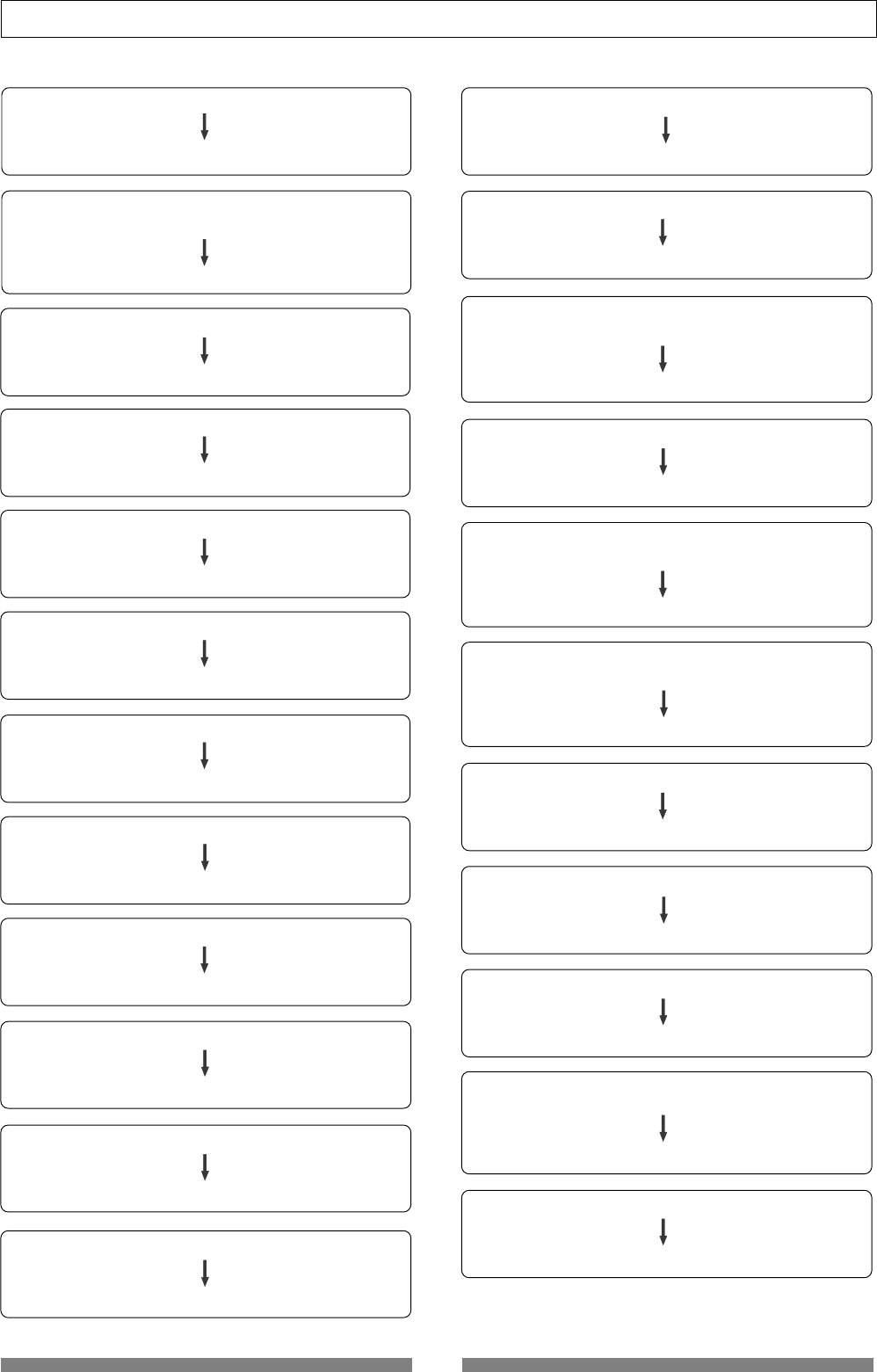
The following shows reference pages where you can find information you need.
See also “The table of contents” shown on page 6.
I want to record my performance.
Please read pages 28 and 30.
I want to replace a part of the previous recording
with a new recording.
Please read page 33.
I want to copy a part of a song to another track.
Please read page 63.
I want to exchange tracks.
Please read page 68.
I want to create multiple programs.
Please read page 61.
I want to control the VF80 via MIDI.
Please read pages 91, 92, and 94.
I want to make my original CD.
Please read page 115.
I want to record audio on a CD or MD disc
to the VF80 digitally.
Please read page 90.
I want to make a backup of song data.
Please read page 96.
I want to use a condenser microphone.
Please read page 27.
I want to equalize the sound.
Please read pages 36 and 40.
I want to delete a program.
Please read page 62.
I want to locate the desired position.
Please read pages 32 and 59.
I want to format a hard disk.
Please read page 20.
I want to mixdown tracks to an external
master recorder.
Please read pages 38 and 76.
I want to know details about the demonstration song.
Please read page 24.
I want to know details about the internal effects.
Please read page 44.
I want to save or load the mixing setting.
Please read page 52.
I want to cue audio at fast speed to search the
desired position.
Please read page 56.
I want to scrub audio to search the desired position.
Please read page 57.
I want to record or playback audio by
altering the speed.
Please read page 58.
I want to record audio with applying the
internal effects.
Please read pages 37, 45, 76 and 83.
Contents
5
I want to put a desired name to a program.
Please read page 62.
I want to record a material while monitoring
the input signal.
Please read page 72.
I want to install the optional CD-RW/CD-R drive.
Please read page 134.
I want to erase unnecessary songs.
Please read pages 62 and 66.
I want to know details about the training mode.
Please read page 74.
I want to know details about the mastering mode.
Please read page 76.
I want to make track bouncing (ping-pong recording).
Please read page 73.
I want to protect a recorded program.
Please read page 129.
I want to save song data by the WAV file format.
Please read page 109.
I want to control panning.
Please read pages 36 and 40.
I want to save song data to a DAT.
Please read page 97.
I want to make a tempo map.
Please read pages 122 and 124.
I want to mixdown tracks without using
an external master recorder.
Please read page 79.
I want to set the MTC offset time.
Please read page 127.
I want to synchronize the VF80 with an external
device.
Please read page 91.
I want to feed the MIDI sync signal to an
external MIDI device.
Please read page 126.
I want to know format information of a hard disk.
Please read page 132.
I want to exchange the hard disk.
Please read page 21.
I want to save song data to a CD-RW/CD-R disc.
Please read page 102.
I want to copy a song recorded on a CD
available on the market.
Please read page 118.
I want to delete unnecessary programs.
Please read page 62.
I want to know details about the insert effect.
Please read page 83.
I want to repeat playback of the desired part.
Please read page 59.

6
Contents
• Safety Instructions ........................................2
• Precautions ........................................................ 3
About power supply ................................................... 3
Precautions upon handling the hard disk ................. 3
Note on repair ............................................................. 3
About copyright.......................................................... 3
About damage ............................................................. 3
Basic Features of VF80
• Product Features................................................ 9
• Before Operating .............................................. 10
RECORDING method ................................................. 10
Program ..................................................................... 10
Remain Indicator ...................................................... 10
Additional track ........................................................ 11
INPUT monitor and REPRO monitor ........................ 11
Event .......................................................................... 11
Trim ........................................................................... 12
Time Base .................................................................. 12
Names and Functions
Top panel (Analog input/output section) .............. 14
Top panel (Mixer section) ........................................ 15
Top panel (Recorder/display section) .................... 16
Rear panel ................................................................. 19
Side Panel .................................................................. 19
About the hard disk storage device
Reformatting the Hard Disk ..................................... 20
Replacing a Hard Disk .............................................. 21
Formatting the New Hard Disk ................................ 23
Basic Recording and Playback
• About a demonstration song! .......................... 24
• Connections of external equipment ................ 25
• LCD ................................................................... 26
Display when turning on the power ........................ 26
Switching the time base ............................................ 26
“Disk remain” indication ......................................... 26
• Preliminary knowledge .................................... 27
Inputs and tracks ...................................................... 27
How to use condenser microphones ........................ 27
• Basic recording (recording onto a single track) .. 28
Preparation for recording ........................................ 28
Contents
Recording .................................................................. 29
Playback .................................................................... 29
• Basic recording (recording onto two track)..... 30
Preparation for recording ........................................ 30
Recording .................................................................. 31
Playback .................................................................... 31
• Mark function ................................................... 32
Setting a mark on the fly .......................................... 32
Locating a mark ........................................................ 32
Deleting a mark ........................................................ 32
• ABS Locate....................................................... 33
• Punch In/Out .................................................... 33
Manual punch in/out using the keys on the unit ... 33
Punch in/out using the Foot Switch ........................ 33
Auto punch in/out function .................................... 34
• Mixing ............................................................... 36
Adjusting levels ........................................................ 36
Setting PAN position ................................................. 36
Adjusting EQ ............................................................. 36
Setting effects ............................................................ 37
• Mix Down .......................................................... 38
Analog Mix Down ...................................................... 38
Digital Mix Down ...................................................... 38
Mixer Functions
• Initial condition when turning the power ......... 39
• Operations while the Normal display is shown 39
Fader .......................................................................... 39
Track mute ................................................................ 39
Master fader mute .................................................... 39
• Mix Parameter Edit ........................................... 40
Adjusting PAN position ...........................................40
Editing EQ ...............................................................41
Preset entries in the EQ library ........................... 42
Setting effects ......................................................... 44
How to make the loop effect setting ....................... 45
Setting effect send levels ..................................... 46
Selecting an effect type ........................................ 47
Selecting pre/post of the effect send .................. 47
Turning the effect processor on or off ................ 48
About the effect types .......................................... 49
Scene memory ........................................................52
Storing the current scene .................................... 52
Recalling a scene .................................................. 52
Deleting a scene ................................................... 53
Fader adjust .......................................................... 53
Scene sequence ......................................................54

Contents
7
Assigning scene memories to the mark map ...... 54
Deleting a mark from the mark map .................. 55
Scene sequence on/off selection ......................... 55
Executing the scene sequence ............................. 55
Recorder Functions
• Cueing .............................................................. 56
Cueing with the [F FWD]/[REWIND] keys ............... 56
Shuttle cueing .........................................................56
Digital scrubbing ..................................................... 57
Performing digital scrubbing .............................. 57
Storing the digital scrub point ............................ 57
• Variable Pitch .................................................... 58
Turning on or off the vari pitch function ............... 58
Setting the Speed ...................................................... 58
• Loop Function .................................................. 59
Setting the start and end points ............................. 59
Capturing the current position on the fly .......... 59
Editing the position via the screen ..................... 59
Setting the start and end points by marks ......... 60
Carrying out the loop playback............................... 60
• Program ............................................................ 61
Creating a new program ........................................... 61
Selecting a program .................................................. 62
Deleting a program ................................................... 62
Editing a program title ............................................. 62
• Track editing ..................................................... 63
Copy & Paste and Move & Paste ............................. 63
Performing Copy (or Move) Paste ....................... 64
Undo/redo of Copy (or Move) Paste ................... 65
Erasing track data ................................................... 66
Erasing .................................................................. 66
Undo/redo of Erase .............................................. 67
Track Exchange ....................................................... 68
Performing the track exchange ........................... 68
• Editing marks ................................................... 69
Viewing the mark list ............................................... 69
Editing a mark position ...........................................69
Enter a mark title ..................................................... 70
Adding a mark ......................................................... 70
Deleting a mark ....................................................... 71
Locating a mark ....................................................... 71
Advanced Operations
• Metronome function......................................... 72
Setting the tempo map ............................................... 72
Setting the metronome output ................................... 72
Setting the time base to bar/beat ............................... 72
Monitoring the metronome sound ............................ 72
• Track bounce (Ping-pong recording) ............... 73
On/Off of bounce mode ............................................. 73
Setting pan position ................................................... 73
Setting level of each track .......................................... 73
Performing the track bounce ..................................... 73
• Training mode ................................................... 74
Connecting the instrument and headphones ........ 74
On/Off of training mode ....................................... 74
Slowing down the playback speed ......................... 75
Changing the pitch ................................................ 75
Canceling the center-positioned sound ................. 75
Setting the cancel position .................................... 75
Boosting the bass sound ........................................ 75
Playing along with the playback sound ................. 75
• Mastering mode ............................................... 76
Selecting a program to be played back .................. 76
On/Off of mastering mode .................................... 76
Setting the mastering effects ................................. 77
On/Off the mastering effects ................................. 77
Recording onto the master recorder ..................... 77
Effect library details .............................................. 77
• Internal mastering function ............................. 79
Rehearsing internal mastering .................................. 80
Performing internal mastering .................................. 81
About Start and End points ................................... 82
• Using the insert effect ...................................... 83
Rehearsal ................................................................. 84
Recording the guitar ................................................. 85
Recording with effect ................................................ 86
• Digital Recording ............................................. 90
Recording an external source onto the VF80 digitally 90
Selecting a program to be recorded ...................... 90
Selecting the digital input ..................................... 90
Selecting a track to record ..................................... 90
Starting to record .................................................. 90
• MIDI Clock Sync System .................................. 91
Connecting to external equipment ........................ 91
Setup of the VF80 .................................................. 92
Executing of recording .......................................... 92
Confirming the MIDI clock sync ............................ 92
• MIDI Sync/MIDI Machine Control System ........ 92
Connecting to external equipment ........................ 93
Setup of external equipment ................................. 93
Setup of the VF80 .................................................. 93
Confirming MTC sync/MMC ................................. 93
Executing of recording .......................................... 93
• External MIDI equipment Sync System by the Slave Mode..94
Connecting to external equipment ........................ 94
Setup of external equipment ................................. 94
Setup of the VF80 .................................................. 94
Confirming chase lock ........................................... 94
Executing of recording .......................................... 95

8
Contents
Save/Load of Song Data
• About Song Data .............................................. 96
Items that can be saved or loaded as song data ......... 97
• Save/load using the S/PDIF digital signal........ 97
Notes for digital audio recorder to be used ................ 97
Notes for saving data using the S/P DIF digital signal 97
Saving data using the S/P DIF digital signal .............. 98
Connecting to an external digital recorder ............ 98
Setting the external recorder ................................. 98
Saving data ............................................................ 98
Loading data using the S/P DIF digital signal .......... 100
Connecting to an external digital recorder .......... 100
Setting the external recorder ............................... 100
Loading data ........................................................ 100
• Save/load using CD-RW/CD-R ....................... 102
Please read this first! ................................................ 102
Saving data using a CD-RW drive (Backup) ............. 104
Loading backup data from a CD-RW drive ............... 107
Saving a WAV file .................................................... 109
Important notes for using a WAV file .................. 109
About WAV file saved .......................................... 112
Loading a WAV file .................................................. 113
Special loading method when using a computer.. 114
Making an audio CD ................................................ 115
Loading from an audio CD ...................................... 118
SETUP Mode
• To enter the SETUP mode .............................. 122
• Time Signature Setting ................................... 122
New Registering of Time Signature .......................... 122
Correcting the Registered Time Signature ............... 122
Deleting of Time Signature ...................................... 122
Clearing All Time Signature data ............................. 122
Changing the Bar Offset Figure ................................ 122
• Setting a Tempo .............................................. 124
New Registering of Tempo ....................................... 124
Correction of the Registered Tempo ........................ 124
Erasing of the Registered Tempo ............................. 124
• Setting the Metronome function .................... 125
• Setting MIDI sync output signal ..................... 126
• Setting an MTC frame rate ............................. 126
• Setting an MTC offset value ........................... 127
• Setting MTC offset mode ............................... 127
• Setting the Slave mode .................................. 128
• Setting the Slave type .................................... 128
• Setting the Record Protect function .............. 129
• Setting Digital Input ....................................... 130
• Setting BAR/BEAT Resolution mode............. 130
• Setting the MIDI device number..................... 131
• Checking the number of track events............ 131
• The Drive Format Information........................ 132
• Fader Fix mode Setting .................................. 132
• Fader Recall mode Setting............................. 133
Appendix
• Installing the CD-1A ....................................... 134
How to install the CD-1A .......................................... 135
Opening/closing the tray ......................................... 136
Placing/removing a disc .......................................... 136
Others
• MIDI Implementation Chart ............................ 137
• MMC Command List ....................................... 138
• Inquiry Message List ...................................... 138
• Maintenance ................................................... 139
• Specifications ................................................ 139
• Block Diagram................................................ 140
• Dimensions .................................................... 141

9
Basic Features of VF80
Basic Features of VF80
The VF80 Digital Multitracker incorporates a digital mixer with an 8-track (plus 16-additional track)
digital recorder.
The digital mixer section features a high-performance DSP multi-effect processor employing the A.S.P.
(Fostex Advanced Signal Processing) technology originally developed by Fostex. The digital recorder
section allows you to record and playback uncompressed linear 16-bit/44.1 kHz digital audio.
You can make all process for music production such as overdubbing, track bounce, effect processing,
mixdown and mastering in the digital domain without sound deterioration.
In addition, by installing the optional CD-RW drive (Model CD-1A), you can save/load to /from CD-
RW/CD-R discs (the WAV file format also supported), as well as create original audio CDs.
Product Features
Mixer Section
• Built in a high-performance DSP multi-effect
processor employing the A.S.P. (Fostex Advanced
Signal Processing) technology
• 7 track faders and a stereo master fader allow you to
control signal levels intuitively.
• The track ON/OFF switch is provided for each track.
The 2-band EQ with the EQ library and the effect send
with PRE/POST selection are provided for Tracks 1
through 6.
• Both balanced (XLR) and unbalanced (1/4" phone)
connectors are provided for each analog input.
The phantom power is also available when using the
balanced connector. Also the trim knob on each input
makes it possible to accept a wide range of input
signals from microphone to line levels.
• "Bounce" function allows bouncing signals from tracks
1 through 6 to tracks 7/8 with a single key operation.
• The mastering mode allows transferring audio on the
master tracks (7/8) to an external recorder with
applying the EQ, reverb and compressor.
• The “REC EFFECT” function allows you to rerecord a
recorded track while applying an effect (insert effect).
Some distortion and simulation effects are available
only for the insert effect.
• "Training mode" helps you to practice your instrument
by slowing down playback, shifting the pitch of the
recorded performance or masking the solo
instrument/voice.
• "Scene memory" function allows you to save and load
up to 99 mixer scenes including fader positions and
EQ/effect settings.
• You can feed the mixed-down signal from the S/PDIF
output connector to an external digital device such as
a DAT recorder for digital recording.
• The “Internal Mastering” function allows you to make
mastering to VF80’s internal tracks, without the need
of an external master recorder.
In addition, by installing the CD-RW drive (Model CD-
1A), you can create original audio CDs using mastered
materials.
Recorder Section
• Employs the Fostex original FDMS-3 (Fostex Disk
Management System-3) format, allowing high quality
recording/playback with uncompressed linear 16-bit/
44.1 kHz digital audio on 8 tracks, as well as 16
additional tracks. You can record about 3 hours of
mono audio per 1 GB disk space.
• Nondestructive audio editing functions such as copy,
paste, move, erase and undo/redo are possible.
• The "Program" function allows you to give a title to
each song and manage up to 99 titles.
• +/- 6.0% pitch control.
• Accepts S/PDIF digital signal and records it directly
onto any VF80 track.
• The auto punch in/out function with rehearsal mode.
The IN and OUT points can be set with 1/100 frame
accuracy. You can also carry out punch in/out manu
ally using the foot switch.
Others
• Dot-matrix LCD and self-illuminating keys allow you
to know the current status visually, as well as to make
settings of the mixer and recorder easily.
• Durable and reliable 3.5-inch E-IDE standard hard
disk is built in.
• Save/load of song data using the S/PDIF (optical)
signal is possible.
• By installing the optional CD-RW drive (Model CD-1A),
you can save/load data to/from CD-RW/CD-R discs.
• Feeds MIDI clock with song position pointer or MTC
(MIDI Time Code).
• Supports MMC (MIDI Machine Control).
• Can be slaved to an external MTC.
• The internal metronome function can be used for
recording a guide track.
• The bar/beat resolution function allows editing by
beat (the clock digit is omitted).
• Up to 99 mark points can be set per each song.
You can locate any mark point or make the mark map
of a scene.
10
Basic Features of VF80
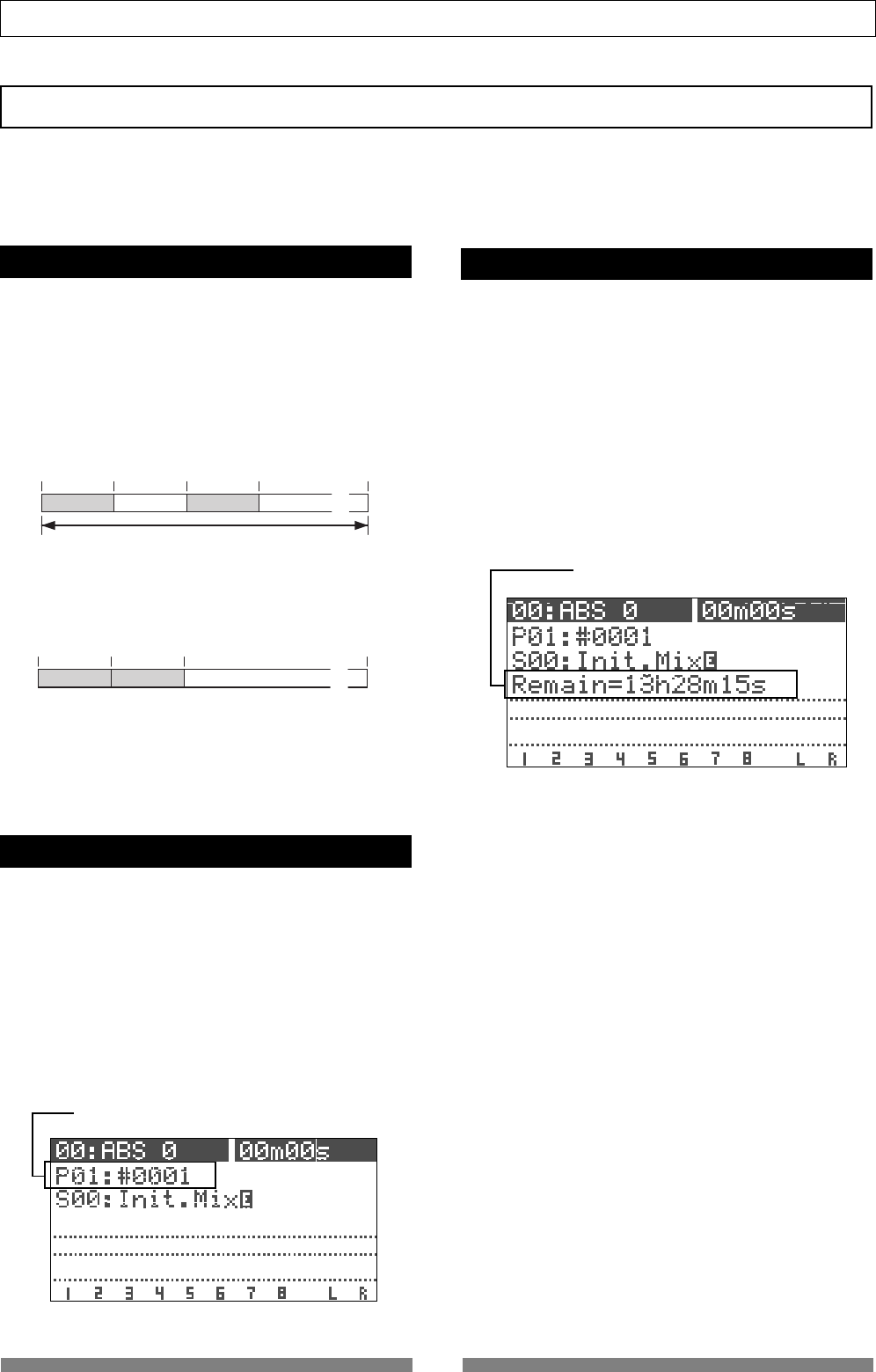
Remain indicator
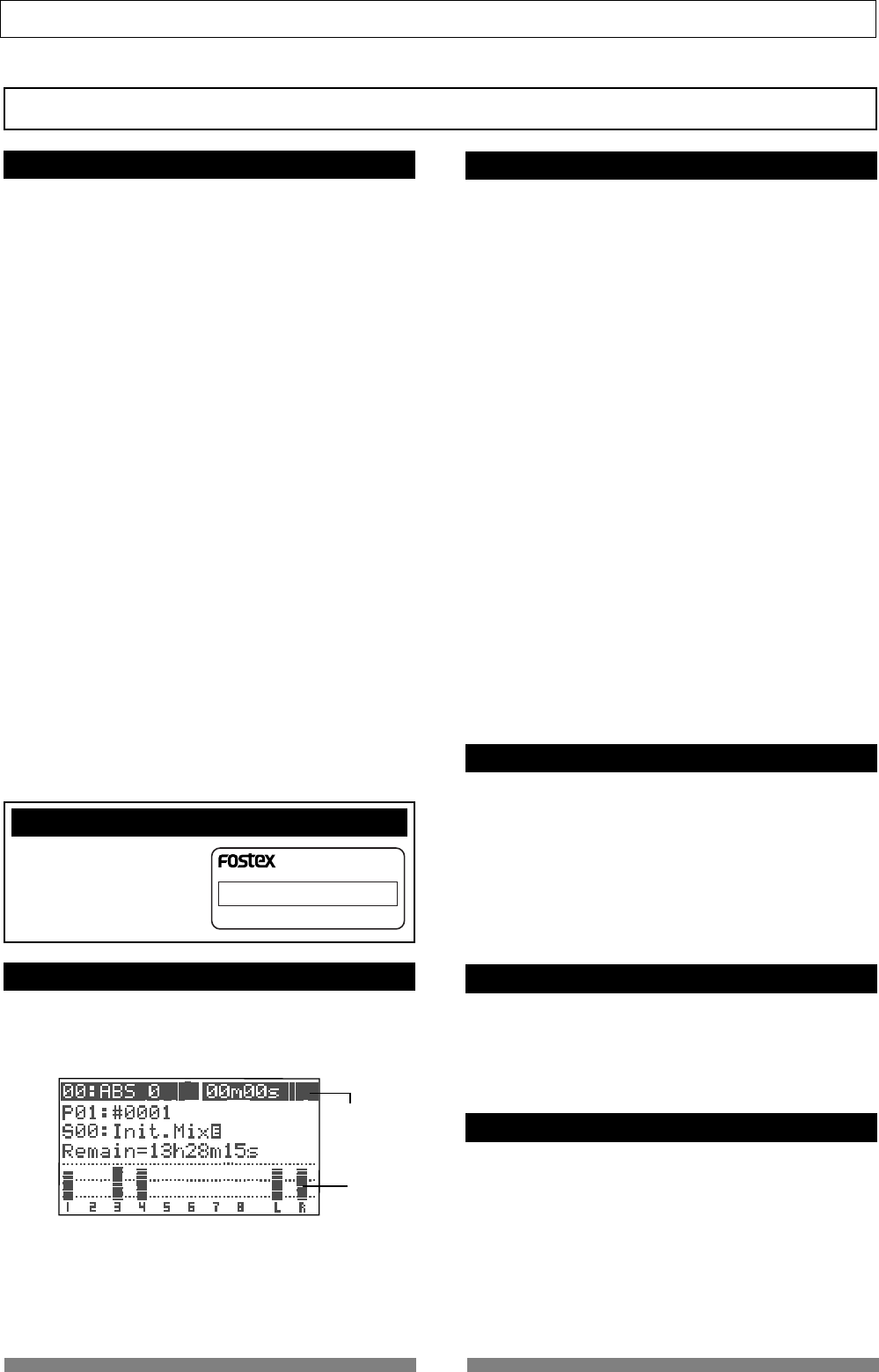
Recording method
Program
Program number/title ("01" is the program number while
"#0001" is a default title)
The remaining time is 13h 28m 15s.
Before Operating
This section describes the basics that you should know before you start operating the VF80.
All users, including those who are familiar with using tape-based Multitracker and those who are new
to Multitracker, should read this section thoroughly to understand the functions of the VF80.
The VF80 uses a hard disk as a recording medium,
instead of a conventional tape.
You can start recording sound sources from any point
on a disk as long as the point is within the range of 24
hours in ABS time. Also you locate any point within
the range. You may think of the VF80 as incorporat-
ing tapes on which 24-hour time information is
striped.
You can record in any area within 24 hours in ABS time.
ABS 0: The beginning time at 00H 00M 00S
REC END: The end time of recording (in the example
above, 00H 15M 00S)
With a tape recorder, the maximum recording time
depends on the tape length, regardless of the amount
of unrecorded areas. With the VF80, you can use the
media more efficiently because no disk space is used
for unrecorded areas.
You can use up to 99 "tapes with 24-hour time infor-
mation" with the VF80. Each "tape" is called a "Pro-
gram".
A program exists independently on the hard disk,
therefore, you can freely record, playback or edit each
program without affecting other programs.
You can give a name (program title) to each program,
so you can easily identify a program.
"Program title" with its program number appears at
the top left of the normal screen as shown below.
The remain indicator shows how much recording time
is left on the current hard disk.
The VF80 program is managed by a 24-hour time
counter, however, the actual recording time left de-
pends on the available disk space.
The remain indicator appears on the LCD during re-
cording (or on REC standby), showing the rough re-
maining time if you record on a mono track.
Note that if the remaining time is 100 hours or more,
the indicator shows the available (remaining) disk
space in MB.
The remaining value is calculated on a mono-track
basis. That is, the value indicates recordable time if
you record on a mono track. You can calculate the
recordable time when recording on more than one
track easily by dividing the time by the track num-
ber.
In the example above, if you record on 2 tracks, the
recordable time is about 6 hours 44 minutes (13 hours
28 minutes 15 seconds divided by 2). Or if you record
on 8 tracks, the recordable time is about 1 hour 41
minutes (13 hours 28 minutes 15 seconds divided by
8).
The VF80 manages up to 99 programs on the hard
disk. Each program includes not only the recording
data but also various setting information which con-
sumes a small amount of disk space. Therefore, note
that the remaining time shown on the screen is a rough
value.
Always check the remaining time left before starting
recording, to ensure that you have enough disk space
to work with.
ABS0
00m 00s 05m 00s 10m 00s REC END
15m 00s 23h 59m 59s
recorded area recorded areaunrecorded area unrecorded area ......
You can record at any point within 24 hours in ABS time.
5 minute recording
unrecorded 5 minute recording 24 hour recording
recorded area recorded area unrecorded area (remain) ......
11
Basic Features of VF80
Input monitor and Repro monitor
EventAdditional track
Track 1
Track 2
Track 3
Track 4
Track 5
Track 6
Track 7
Track 8
Track 9
Track 10
Track 11
Track 12
Track 13
Track 14
Track 15
Track 16
Track 17
Track 18
Track 19
Track 20
Track 21
Track 22
Track 23
Track 24
A program on the VF80 consists of 24 tracks. Tracks
1 through 8 are called "Real tracks" which you can
record, playback and edit. Tracks 9 through 24 are
called "Additional tracks". Using the "Track Exchange"
function, you can exchange between "real track(s)"
and "additional track(s)" in one-track, 2-track or 8-
track block.
This makes it possible to record solo on several tracks,
exchange tracks and compare the results, or to record
different rhythm versions using multiple tracks, ex-
change the rhythm tracks completely and making a
remix version.
Note that tracks 9 through 24 cannot be recorded,
played or edited. The tracks you want to work with
must be set as tracks 1 through 8.
There are two modes for monitoring a track of the
VF80 ; "Repro monitor" and "Input monitor".
"Repro monitor" means that the track playback sig-
nal is monitored.
"Input monitor" means that the input source of the
track is monitored. You can check the signal level for
recording in this mode.
Input monitor is only available for tracks to be re-
corded (on REC standby) or currently being recorded.
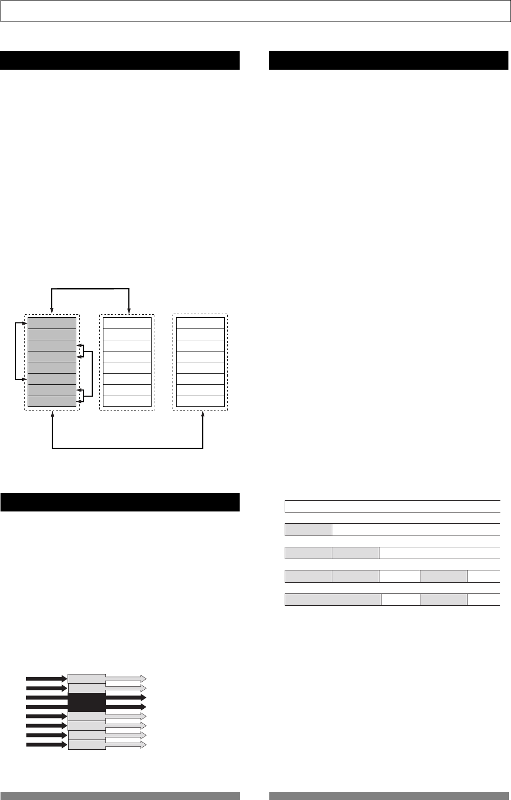
Each time you make a recording, an independent
audio file is created on each recorded track. A silent
part on a track is also recognized as a file.
These files (audio files and silent files) are called
"events".
With the VF80, you can create up to 512 events per
track. You cannot make any further recording when
512 events are created. In the normal use, 512 events
are enough.
The VF80 can show the current number of events on
the LCD. It also shows a warning message if you are
going to make recording when 512 events already
exist. You may resolve this problem by saving the
program (see "Save/Load of a program").
Let's count the events for each recording step (A
through E) below.
A.Before recording, there is a single event (silent file) on the track
(the VF80 recognizes a silent part as a file).
B.After making a recording (REC B), there are two events on
the track; the recorded audio file and the following silent part.
C.After making another recording (REC C) continuously from
the end point of REC B, there are three events on the track;
two audio files and the following silent part.
D.After locating a point ahead of REC C and then making an
other recording (REC D), there are totally five events on the
track. Note that a silent file is created between Rec C and Rec
D.
E.After making a recording (REC E) over REC B and REC C,
there are four events on the track.
Signal input in the recorder Signal output from the recorder
1 track
5 track
6 track
3 track
READY
4 track
READY
Playback sound (Playback monitor)
Playback sound (Playback monitor)
Playback sound (Playback monitor)
Input signal (Input monitor)
Input signal (Input monitor)
2 track
Playback sound (Playback monitor)
7 track
8 track
Playback sound (Playback monitor)
Playback sound (Playback monitor)
A Silence
B SilenceRec B
C Rec B Rec C Silence
D Rec B Rec C Silence SilenceRec D
E Rec E Silence SilenceRec D
8 track block exchange
8 track block exchange
2 track block exchange
One track exchange
12
Basic Features of VF80
Time Base
.....
.....
.....
ABS
MTC
00M 00S 00M 03S 00M 06S
00H 59M 57S 01H 00M 00S 01H 00M 03S
BAR/ /CLK
001BAR 1- 002BAR 1 002BAR 1
ABS 0
The term "Time base" frequently appears in this
manual. The time base is used to show the location in
the recorder, like the "tape counter" of conventional
tape recorders.
There are three types of time bases:
1. ABS (Absolute time)
2. Bar/Beat/Clk (Bar/Beat/Clock)
3. MTC (MIDI Time Code)
You can switch between these time bases by pressing
the [TIME BASE SEL] key.
The ABS shows the absolute time of each program and
is striped from 00h 00m 00s (=ABS 0) to 23h 59m 59s
when a program is created.
The example below shows the current recorder posi-
tion is at 00m (minute) 00s (second) 00f (frame).
The hour digit appears only when the ABS time ex-
ceeds 01h 00m 00s 00f.
ABS 0 is the reference position for managing all the
location and related to other time bases.
Bar/Beat/Clk shows the musical position generated
from the internal tempo map of the VF80 (including
time signature and tempo).
The example below shows the current recorder posi-
tion is at beat 1 of bar -2.
This position (beat 1 of bar -2) corresponds to ABS 0
and the following bar/beat numbers are determined
according to the time signature and tempo settings.
Beat 1 of bar -2 corresponds to ABS 0 as the default
setting, however, you can change to set it between bar
-9 and bar -2.
MTC (MIDI Time Code) runs in sync with the ABS time.
The MTC value (**h **m **s) corresponding to ABS 0
can be set, which is called "MTC offset".
If you set the MTC offset to 01h 00m 00s, the MTC will
start from 01h 00m 00s, and at the ABS 00h 00m 00s
position, the MTC value will be 02h 00m 00s
The example below shows that the current position is
at MTC 00h 59m 57s
The default MTC offset is 00h 59m 57s 00f 00sf. You
can change the offset to any time value of 24-hour
clock.
It is also possible to set the MTC offset by setting the
MTC value corresponding to "beat 1 of bar 1" instead
of "ABS 0".
The following diagram illustrates the relationship
between the three time bases.
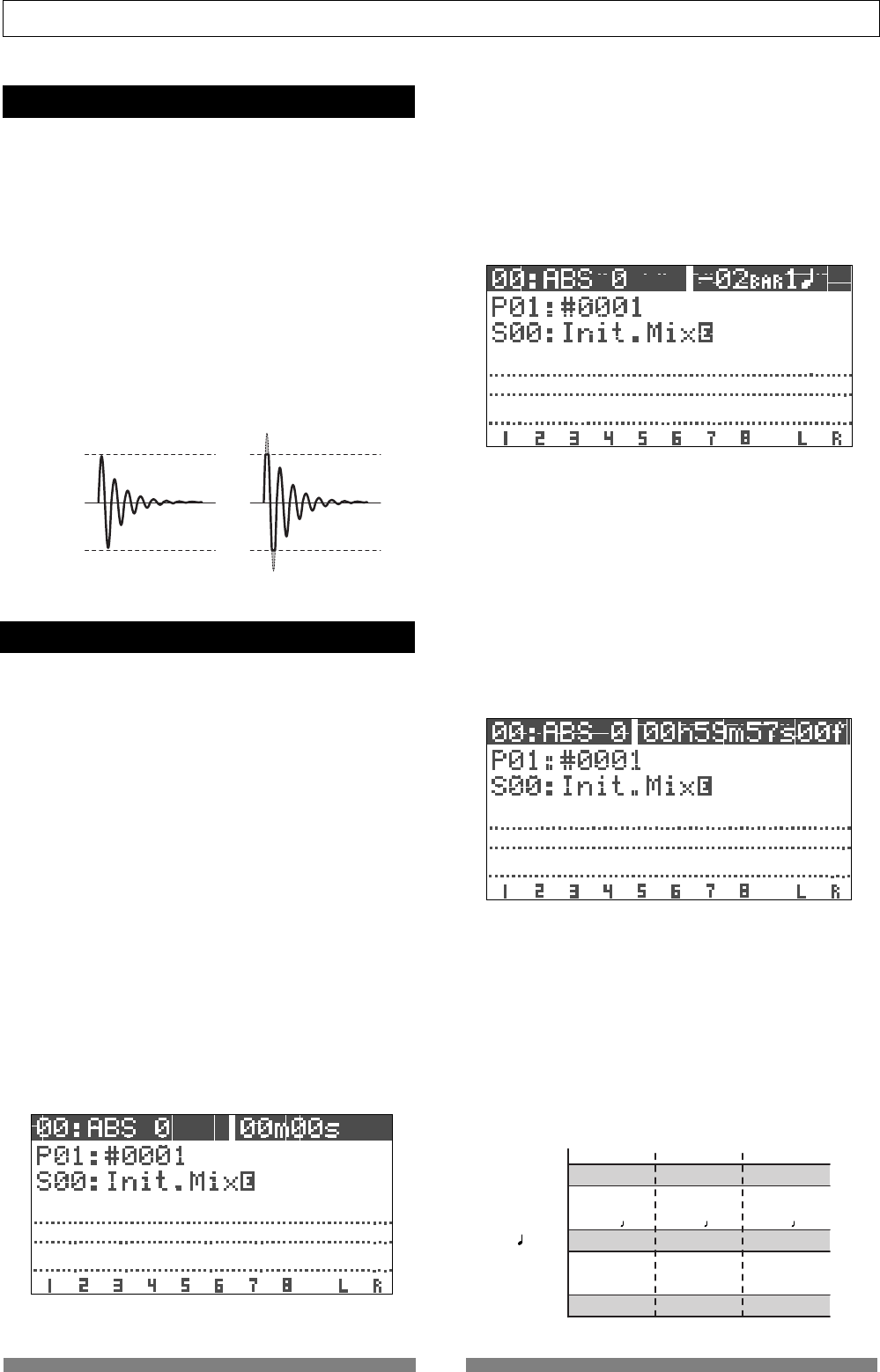
Trim
It is important to set the analog input level appropri-
ately when converting an analog input signal from
[INPUT] A or B into a digital signal (A/D conversion).
You can adjust the analog level using the [TRIM] con-
trol. The [PEAK] indicator lights if the level is too high.
If the [TRIM] setting is not appropriate and the ana-
log input level is too high (if the PEAK indicator lights),
the signal will be converted into a distorted digital
signal, resulting digital noise. You cannot eliminate
this distortion/noise from the sound in the following
stages. Therefore, be sure to adjust the level appro-
priately using the [TRIM] knob not to light the [PEAK]
indicator when receiving the loudest audio input sig-
nal.
Clip level
Clip level
Appropriate gain Excessive gain
13
Names and functions
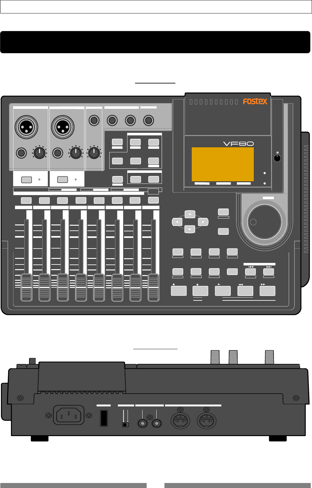
Rear panel
Top panel
OFF
ON
MIDI
OUTPUT INPUT OUTPUT
INPUT
POWER PHANTOM S/P DIF / DATA
DIGITAL MULTITRACKER
LOCATE ABS 0
LOCATE REC END
SEL
TIMEBASE
CURSOR
PHANTOM
ACCESS
PEAK
CH ON/OFF
LR
GUITAR
GUITAR
LINE MIC LINE MIC MIN MAX
MASTERING TRAINING
EFFECTEQPAN
SCENE SEQ.SCENE
TRACK
UNDO
SETUP
PUNCH
AUTO LOOP PITCH SCRUB
VARI
F FWDREWINDPLAYSTOPRECORD
EXIT
ENTER
TRIMTRIM
WAVE FORM
MIX PARAMETER
PGM FADER MAP
ON/OFF
2TRK MODE
F1 F2 F3 SHIFT
EDIT EDIT EDIT MARK DELETE
LOCATE
FOOT SW
ST OUT
PHONES
INPUT A
BOUNCE
INPUT B
+6
-10
-20
-40
-
∞
-30
0
+6
-10
-20
-40
-
∞
-30
0
+6
-10
-20
-40
-
∞
-30
0
+6
-10
-20
-40
-
∞
-30
0
+6
-10
-20
-40
-
∞
-30
0
+6
-10
-20
-40
-
∞
-30
0
+6
-10
-20
-40
-
∞
-30
0
+6
-10
-20
-40
-
∞
-30
0
PEAK
CH ON/OFF
2 3 4 5 6 7/8 2TRK1 MASTER
TRACK STATUS / TRACK SEL
TRACK STATUS
RED REC GREEN PLAY OFF MUTE STATUS
/SEL
EJECT
/YES
/NO
SHUTTLE
JOG
UNBAL UNBAL
BAL
BAL
F1 F2 F3
EDIT
/REDO
REC EFF
Names and Functions
14
Names and functions
DIGITAL MULTITRACKER
LOCATE ABS 0
LOCATE REC END
SEL
TIMEBASE
CURSOR
PHANTOM
ACCESS
PEAK
CH ON/OFF
LR
GUITAR
GUITAR
LINE MIC LINE MIC MIN MAX
MASTERING TRAINING
EFFECTEQPAN
SCENE SEQ.SCENE
TRACK
UNDO
SETUP
PUNCH
AUTO LOOP PITCH SCRUB
VARI
F FWDREWINDPLAYSTOPRECORD
EXIT
ENTER
TRIMTRIM
WAVE FORM
MIX PARAMETER
PGM FADER MAP
ON/OFF
2TRK MODE
F1 F2 F3 SHIFT
EDIT EDIT EDIT MARK DELETE
LOCATE
FOOT SW
ST OUT
PHONES
INPUT A INPUT B
+6
-10
-20
-40
-
∞
-30
0
+6
-10
-20
-40
-
∞
-30
0
+6
-10
-20
-40
-
∞
-30
0
+6
-10
-20
-40
-
∞
-30
0
+6
-10
-20
-40
-
∞
-30
0
+6
-10
-20
-40
-
∞
-30
0
+6
-10
-20
-40
-
∞
-30
0
+6
-10
-20
-40
-
∞
-30
0
PEAK
CH ON/OFF
2345 6 7/8 2TRK1 MASTER
TRACK STATUS / TRACK SEL
TRACK STATUS RED REC GREEN PLAY OFF MUTE STATUS
/SEL
EJECT
/YES
/NO
SHUTTLE
JOG
UNBAL UNBAL
BAL
BAL
F1 F2 F3
EDIT
/REDO
BOUNCE
REC EFF
123456789
10
11
12
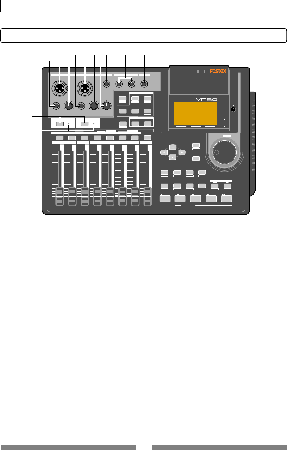
Top panel (Analog input/output section)
5. [INPUT B/BAL] (Balanced) connector
• Connects to the balanced output of an external sound
source.
• Reference input level: -50 dBV to +2 dBV (approx. -48
dBu to +4 dBu)
• Connector type: XLR-3-31 type (pin #2 hot)
• A phantom power (+48 V) can be supplied for using a
condenser microphone by setting the [PHANTOM]
switch on the rear panel to ON.
• When the [INPUT B/UNBAL] connector is plugged, the
input from this connector is interrupted.
6. [INPUT B/TRIM] knob
• Controls the gain according to the signal from [INPUT B].
• You can adjust the gain to accept input signals between
-50 dBV (MIC) and +2 dBV (LINE).
7. [PHONES] (Headphones) knob
• Adjusts the level of headphones for monitoring.
8. [PHONES] (Headphones) connector
• Connects headphones for monitoring.
• Connector type: TRS phone jack
9. [ST OUT L. R] (Stereo out) connector
• Outputs the stereo (L and R) buss signal.
• Connects to a master recorder, etc.
• Reference output level: -10 dBV
• Connector type: phone jack
1. [INPUT A/UNBAL] (Unbalanced) connector
• Connects to the unbalanced output of an external sound
source.
• Reference input level: -50 dBV to +2 dBV
• Connector type: phone jack
• When this connector is plugged, the input from the
[INPUT A/BAL] connector is interrupted.
2. [INPUT A/BAL] (Balanced) connector
• Connects to the balanced output of an external sound
source.
• Reference input level: -50 dBV to +2 dBV (approx. -48
dBu to +4 dBu)
• Connector type: XLR-3-31 type (pin #2 hot)
• A phantom power (+48 V) can be supplied for using a
condenser microphone by setting the [PHANTOM]
switch on the rear panel to ON.
• When the [INPUT A/UNBAL] connector is plugged, the
input from this connector is interrupted.
3. [INPUT A/TRIM] knob
• Controls the gain according to the signal from [INPUT
A].
• You can adjust the gain to accept input signals between
-50 dBV (MIC) and +2 dBV (LINE).
4. [INPUT B/UNBAL] (Unbalanced) connector
• Connects to the unbalanced output of an external sound
source.
• Reference input level: -50 dBV to +2 dBV
• Connector type: phone jack
• When this connector is plugged, the input from the
[INPUT B/BAL] connector is interrupted.
15
Names and functions
DIGITAL MULTITRACKER
LOCATE ABS 0
LOCATE REC END
SEL
TIMEBASE
CURSOR
PHANTOM
ACCESS
PEAK
CH ON/OFF
LR
GUITAR
GUITAR
LINE MIC LINE MIC MIN MAX
MASTERING TRAINING
EFFECTEQPAN
SCENE SEQ.SCENE
TRACK
UNDO
SETUP
PUNCH
AUTO LOOP PITCH SCRUB
VARI
F FWDREWINDPLAYSTOPRECORD
EXIT
ENTER
TRIMTRIM
WAVE FORM
MIX PARAMETER
PGM FADER MAP
ON/OFF
2TRK MODE
F1 F2 F3 SHIFT
EDIT EDIT EDIT MARK DELETE
LOCATE
FOOT SW
ST OUT
PHONES
INPUT A
BOUNCE
INPUT B
+6
-10
-20
-40
-
∞
-30
0
+6
-10
-20
-40
-
∞
-30
0
+6
-10
-20
-40
-
∞
-30
0
+6
-10
-20
-40
-
∞
-30
0
+6
-10
-20
-40
-
∞
-30
0
+6
-10
-20
-40
-
∞
-30
0
+6
-10
-20
-40
-
∞
-30
0
+6
-10
-20
-40
-
∞
-30
0
PEAK
CH ON/OFF
2345 6 7/8 2TRK1 MASTER
TRACK STATUS / TRACK SEL
TRACK STATUS RED REC GREEN PLAY OFF MUTE STATUS
/SEL
EJECT
/YES
/NO
SHUTTLE
JOG
UNBAL UNBAL
BAL
BAL
F1 F2 F3
EDIT
/REDO
REC EFF
13
14
15 16
17
18
19
20
21
23
24
22
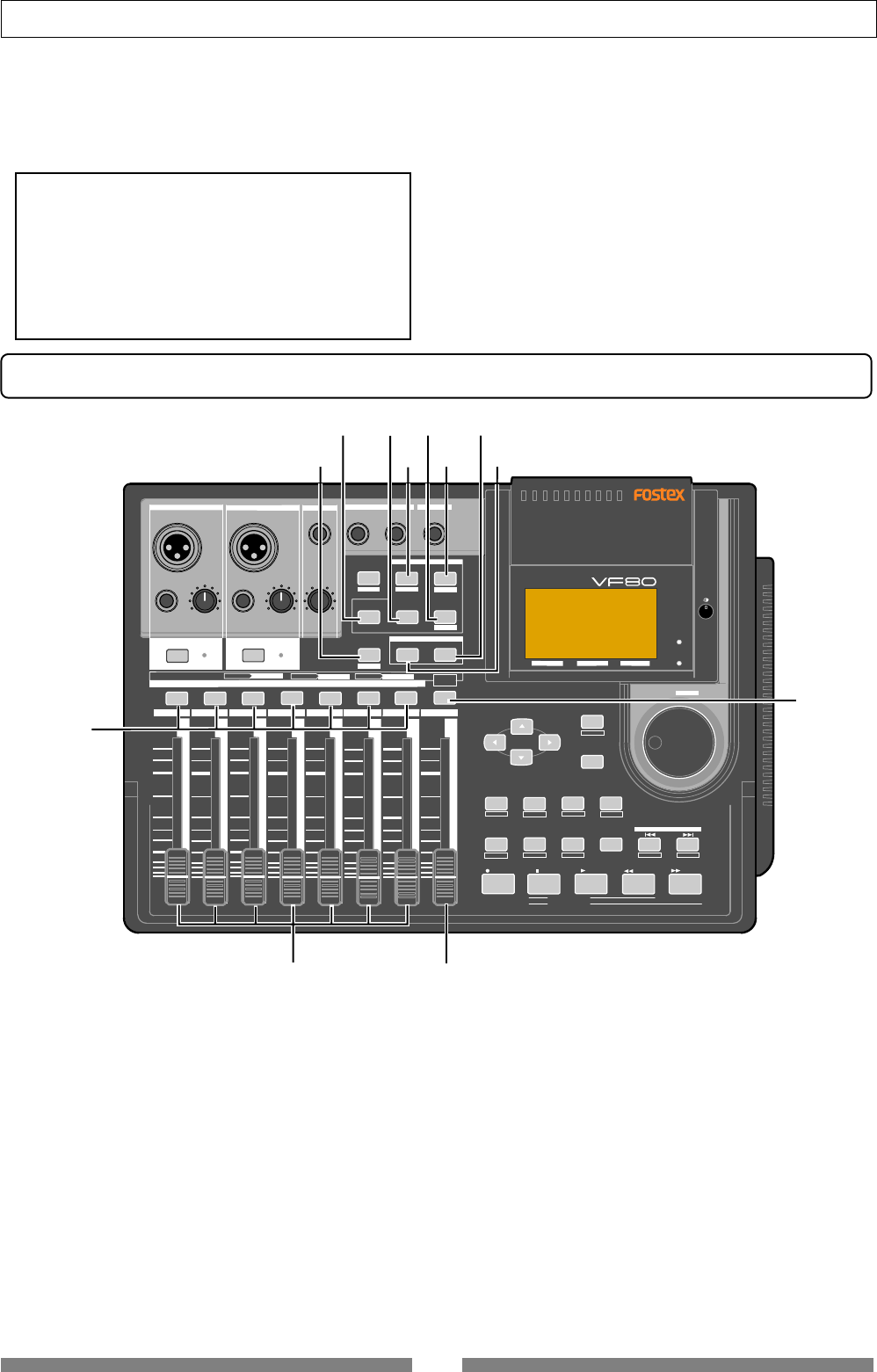
Top panel (Mixer section)
11. [PEAK] indicators
• Each indicator lights up when the corresponding input
signal reaches the clipping level.
• Set the [TRIM] knob properly not to light the indicator.
12. [CH ON/OFF] keys
• Each key is used to turn on and off of the
corresponding channel. When on, the key illuminates.
See the following description for details about how to use
each element.
10. [FOOT SW] (Foot switch) connector
• Connects to an optional foot switch (Model 8051) for
punch in/out operation.
• Connector type: phone jack
13. [TRACK STATUS/TRACK SEL] keys
• While stopped, each key is used to change the track
status among OFF, PLAY and REC (READY).
During playback, pressing the key switches between OFF
and PLAY.
During recording, you cannot change the track status.
• When you view or edit mixer parameters such as pan
and EQ in the "Mix parameter edit" mode (described
later), you can select the target track by pressing the
corresponding [TRACK STATUS/TRACK SEL] key.
• The illumination of each key shows the track status as
follows.
* flashing in red: the track is in REC READY.
* lighting in red: the track is being recorded.
* lighting in green: the track can be played back.
* not lighting (off): the track is muted.
14. [BOUNCE] key
• Turns the bounce mode on or off.
When on (the key lights), tracks 7-8 are automatically
armed for recording, allowing track 1 through 5 signals
to bounce to track 7 and 8.
• Pressing this key while holding down the [SHIFT] key
enters the “REC EFFECT” mode, in which rerecording a
recorded track with applying the “insert effect” is
possible. While the “REC EFFECT” mode is active, the
[BOUNCE] key flashes in red. To exit the “REC EFFECT”
mode, press the [BOUNCE] key again.
15. [MIX PARAMETER-PAN] key
• When viewing or editing the pan pot setting, press this
key.
• Select the track to be viewed or edited by pressing the
corresponding [TRACK STATUS/TRACK SEL] key.
<Caution>
Do not power on the machine with non-specified foot
SW connected to the foot SW jack. When powering on
the machine with non-specified foot SW (latch type foot
SW, etc.) connected to the foot SW jack, there is a case
that the machine does not correctly boot up with “No
Drive!” alter message. In such a case, power off the
machine once, disconnect the foot SW and then power
back on.
16
Names and functions
DIGITAL MULTITRACKER
LOCATE ABS 0
LOCATE REC END
SEL
TIMEBASE
CURSOR
PHANTOM
ACCESS
PEAK
CH ON/OFF
LR
GUITAR
GUITAR
LINE MIC LINE MIC MIN MAX
MASTERING TRAINING
EFFECTEQPAN
SCENE SEQ.SCENE
TRACK
UNDO
SETUP
PUNCH
AUTO LOOP PITCH SCRUB
VARI
F FWDREWINDPLAYSTOPRECORD
EXIT
ENTER
TRIMTRIM
WAVE FORM
MIX PARAMETER
PGM FADER MAP
ON/OFF
2TRK MODE
F1 F2 F3 SHIFT
EDIT EDIT EDIT MARK DELETE
LOCATE
FOOT SW
ST OUT
PHONES
INPUT A INPUT B
+6
-10
-20
-40
-
∞
-30
0
+6
-10
-20
-40
-
∞
-30
0
+6
-10
-20
-40
-
∞
-30
0
+6
-10
-20
-40
-
∞
-30
0
+6
-10
-20
-40
-
∞
-30
0
+6
-10
-20
-40
-
∞
-30
0
+6
-10
-20
-40
-
∞
-30
0
+6
-10
-20
-40
-
∞
-30
0
PEAK
CH ON/OFF
2 3 4 5 6 7/8 2TRK1 MASTER
TRACK STATUS / TRACK SEL
TRACK STATUS RED REC GREEN PLAY OFF MUTE STATUS
/SEL
EJECT
/YES
/NO
SHUTTLE
JOG
UNBAL UNBAL
BAL
BAL
F1 F2 F3
EDIT
/REDO
BOUNCE
REC EFF
26 27 28
29
30
31
32
33
34
35
36
37
38394041
42
4344
454647
48
25
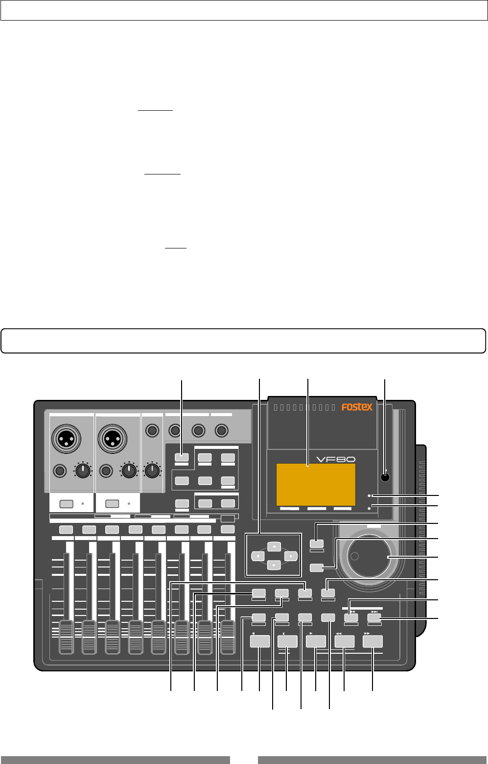
Top panel (Recorder/Display section)
20. [2TRK MODE-TRAINING] key
• Turns on or off the "Training mode" in which only tracks
7-8 are played back. When the mode is active, the key
lights up.
21. [2TRK MODE-MASTERING] key
• Turns on or off the "Mastering mode" in which tracks
7-8 are played back with sound processing (the EQ,
reverb and compressor). When the mode is active, the
key lights up.
22. [STATUS/SEL-MASTER] key
• Turns on or off the master channel.
• Also used to select the track for the mix parameter edit.
23. [MASTER] fader
• Adjusts the output levels of the stereo L/R busses.
24. Track faders
• Adjusts the playback levels of the tracks 1 through 6 and
7-8.
16. [MIX PARAMETER-EQ] key
• When viewing or editing the EQ setting, press this key.
• Select the track to be viewed or edited by pressing the
corresponding [TRACK STATUS/TRACK SEL] key.
17. [MIX PARAMETER-SCENE / FADER] key
• When storing, recalling or deleting a scene memory,
press this key.
• To view track fader positions, press this key while de
pressing the [SHIFT] key.
18. [MIX PARAMETER-EFFECT / ON/OFF] key
• When selecting the internal DSP effects, adjusting the
effect send levels, selecting pre or post of the effect send,
or setting effect parameters, press this key.
• Select the track to be viewed or edited by pressing the
corresponding [TRACK STATUS/TRACK SEL] key.
19. [MIX PARAMETER-SCENE SEQ. / MAP] key
• Turns on or off the scene sequence mode.
• When editing the scene sequence map, press this key
while depressing the [SHIFT] key.
17
Names and functions
<Caution>
Do not turn off the VF80 power while this indicator
lights. Data recorded in the disk may be erased.
25. [TRACK EDIT / PGM] key
• When editing audio of tracks such as copy/paste, etc.,
press this key.
There are four audio editing functions.
a. copy
b. move
c. erase
d. track exchange
• Pressing this key while depressing the [SHIFT] key
allows you to carry out the following program-related
functions.
a. creating a new program
b. selecting a program
c. editing a program title
d. deleting a program
26. [CURSOR / / / ] keys
• Used to move the edit point in edit or setup mode.
27. LCD (Liquid Crystal Display)
• Displays the recorder or mixer status or parameters.
28. Contrast adjusting knob
• Adjusts the LCD contrast.
Turning the knob clockwise makes the contrast higher,
while turning it counterclockwise makes it lower.
29. [ACCESS] indicator
• Lights up while the internal hard disk drive or external
backup SCSI device is writing or reading data.
30. [PHANTOM] indicator
• Lights up when the phantom power is supplied.
You can switch the phantom power on or off by the
[PHANTOM] switch on the rear panel.
31. [EXIT/NO / EJECT] key
• Used to cancel or interrupt SETUP menu settings or
audio editing functions such as Copy and Paste.
The opposite of the [ENTER/YES] key.
32. [ENTER/YES] key
• Used to execute SETUP menu settings or audio editing
functions such as Copy and Paste. The opposite of the
[EXIT/NO / EJECT] key.
33. [JOG / SHUTTLE] dial
• When the [WAVE FORM SCRUB] key is illuminated, after
pressing any of the [TRACK STATUS/TRACK SEL] keys,
rotating this dial scrubs audio digitally with no pitch
change for both forward and backward directions.
• Used to change a parameter value in the edit mode.
• Pressing this dial while holding down the [SHIFT] key
moves the position forward or backward at 1x to 64x
speed depending on the rotating direction and degree.
34. [SHIFT] key
• Used to activate the second (shifted) functions of keys
and a dial. Each shifted function is labeled in a while-
line boxes on the panel.
35. [LOCATE | / MARK] key
• Each press of this key locates the previous mark point.
• Pressing this key while holding down the [SHIFT] key
stores the current position in the mark map.
36. [LOCATE | / DELETE] key
• Each press of this key locates the next mark point.
• Pressing this key while holding down the [SHIFT] key
delete the current mark point directly.
37. [F FWD ] key
• Pressing this key while stopped fast-forwards the
position at 30x speed.
• Pressing this key during playback moves forward the
position at 3x speed with audible cue.
• Pressing this key while holding down the [STOP] key
executes the "LOCATE REC END" function (locates the
last recording position of the current program).
38. [REWIND ] key
• Pressing this key while stopped rewinds the position at
30x speed.
• Pressing this key during playback moves backward the
position at 3x speed with audible cue.
• Pressing this key while holding down the [STOP] key
executes the "LOCATE ABS 0" function (locates the
beginning of the current program).
39. [PLAY] key
• Pressing this key starts the recorder playback.
• Pressing the [RECORD] key while holding down this key
(or pressing this key while holding down the [RECORD]
key) starts recording of the armed (REC READY) track(s).
• Pressing this key alone during recording punches out
(releases recording).
• Pressing this key while holding down the [STOP] key
locates the last playback position.
40. [STOP] key
• Pressing this key during playback, recording, fast-
forward or rewinding stops the recorder running.
• Also used to cancel or interrupt SETUP menu settings
or audio editing functions such as Copy and Paste.
• Pressing the [F FWD] or [REWIND] key while holding
down this key executes the "LOCATE REC END" or
"LOCATE ABS 0" function.
• Pressing the [PLAY] key while holding down this key
locates the last playback position.
• Pressing the [RECORD] key while holding down this key
locates the last recording position.
41. [RECORD] key
• Pressing the [PLAY] key while holding down this key (or
pressing this key while holding down the [PLAY] key)
starts recording of the armed (REC READY) track(s).
• Pressing this key alone switches the monitor of the
armed track (s) to Input monitor (the [RECORD] key
flashes).
Pressing this key again switches the monitor back to
Repro monitor.
• Pressing this key while holding down the [STOP] key
locates the last recording position.
18
Names and functions
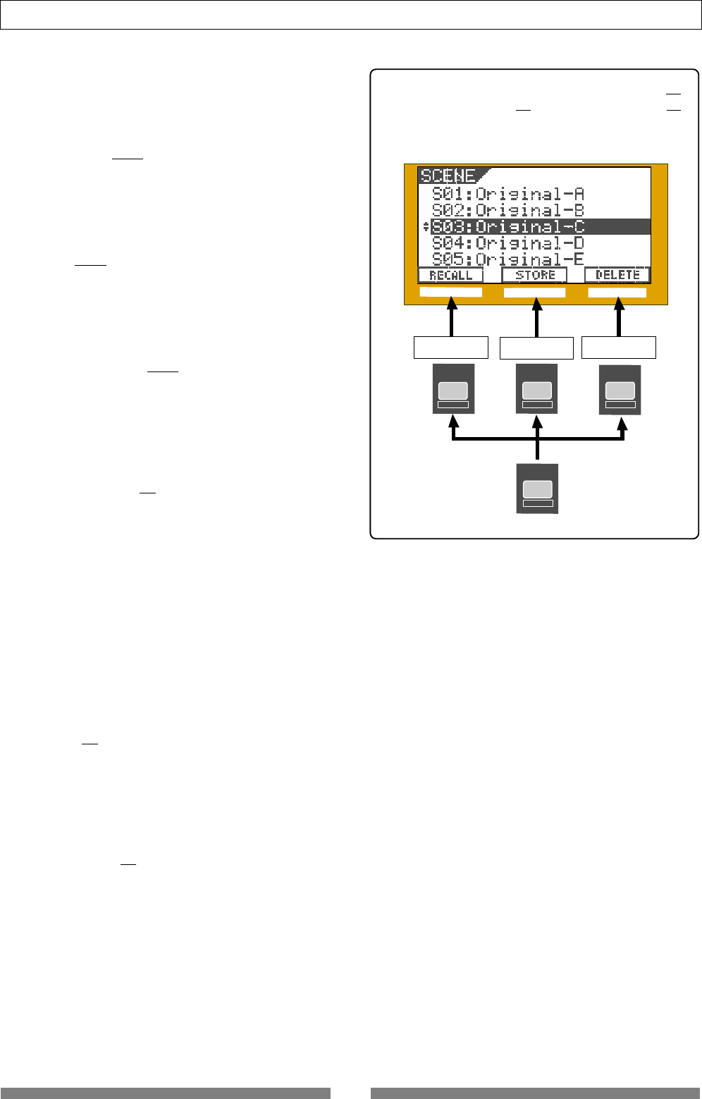
In the example below, pressing the [SETUP / F1]
key, [TIME BASE SEL / F2] key or [UNDO/REDO / F3]
key executes "RECALL", "STORE" or "DELETE" re-
spectively.
SHIFT
UNDO / REDO
F3
SEL
TIMEBASE
F2
SETUP
F1
F1 F2 F3
Recalling a scene Storing a scene Deleting a scene
42. [WAVE FORM SCRUB] key
• Pressing this key enters the scrub mode. In the scrub
mode, you can scrub audio forward or backward
digitally.
43. [VARI PITCH / EDIT] key
• Pressing this key switches between On and Off of the vari
pitch (vari-speed playback/recording) function.
When the function is active, this key is illuminated.
• Pressing this key while holding down the [SHIFT] key
makes you ready to edit the pitch value via the screen.
44. [LOOP / EDIT] key
• Pressing this key switches between On and Off of the loop
mode. When the mode is active, this key is illuminated.
• Pressing this key while holding down the [SHIFT] key
makes you ready to edit the loop parameters (Start point
and End point) via the screen.
45. [AUTO PUNCH I/O / EDIT] key
• Pressing this key switches between On and Off of the auto
punch mode. When the mode is active, this key is
illuminated.
• Pressing this key while holding down the [SHIFT] key
makes you ready to edit the auto punch parameters (In
point and Out point) via the screen.
46. [TIME BASE SEL / F2] key
• Pressing this key switches the time base shown on the
screen among the following.
a. ABS (absolute time):
Absolute time from 00h00m00s to 23h59m59s.
b. Bar/Beat/Clk (Bar/Beat/Clock):
Bar/Beat/Clock according to the time signature and
tempo information set in the internal tempo map.
c. MTC (MIDI Time Code)
MTC with or without an offset to the ABS time.
• When a key icon is shown above "F2" on the screen,
pressing this key while holding down the [SHIFT] key
executes the function directly.
47. [SETUP / F1] key
• Pressing this key enters the setup mode for editing/
setting the initial setting parameters of recorder and
mixer.
• When a key icon is shown above "F1" on the screen,
pressing this key while holding down the [SHIFT] key
executes the function directly.
48. [UNDO/REDO / F3] key
• Pressing this key cancels the operation for the audio
editing (Copy, Paste, etc.), auto punch in/out or
recording, and returns to the previous condition.
This is the "undo" function.
• Pressing this key again returns to the condition before
carrying out the "undo" function. This is the "redo"
function.
• When a key icon is shown above "F3" on the screen,
pressing this key while holding down the [SHIFT] key
executes the function directly.
19
Names and functions
OFF
ON
MIDI
OUTPUT INPUT OUTPUT
INPUT
POWER PHANTOM S/P DIF / DATA
49 50 51 52 53 54 55
56
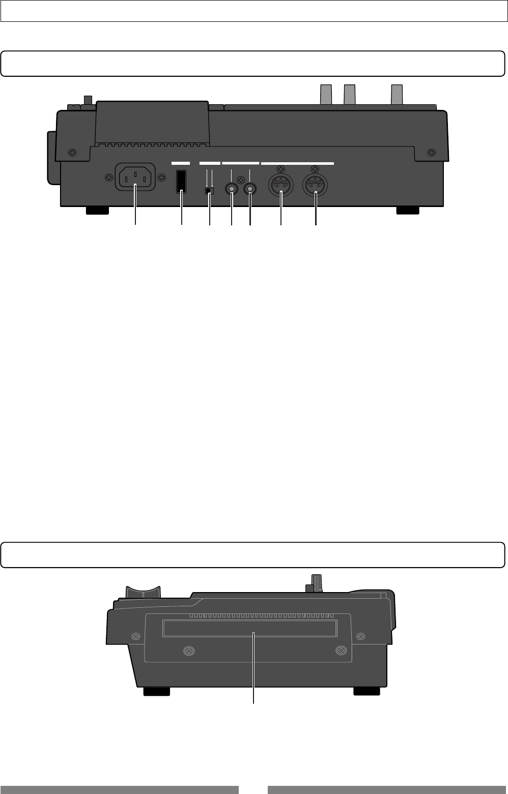
Rear panel
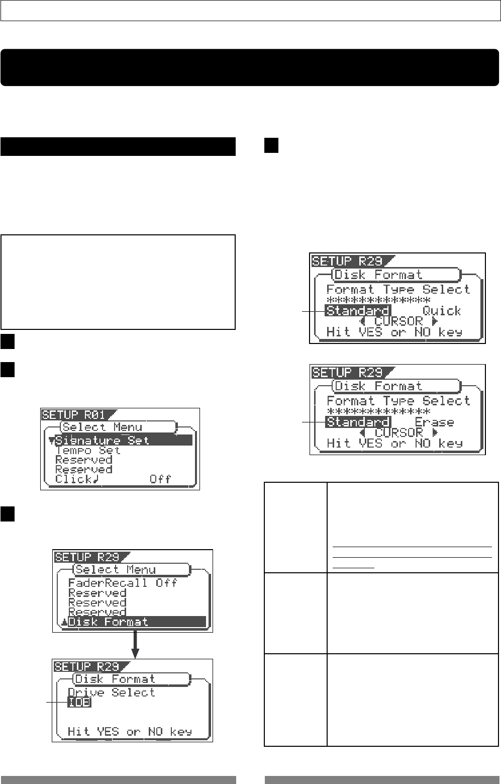
Side panel
56. Slot for the optional CD-RW drive
• You can install the Model CD-1A optional CD-RW drive
in this slot.
• See page 134 for details about how to install the optional
CD-RW drive.
If you want to know details about the option, contact
your dealer or a Fostex sales office.
49. [AC IN] connector
• Connects the supplied AC power cord. Make sure that
the voltage of your AC outlet matches the specified
voltage.
50. [POWER] switch
• Turns on or off the power of the unit.
51. [PHANTOM] ON/OFF switch
• When the switch is set to ON, the phantom power is
supplied to the condenser microphone(s) connected to
the [INPUT A/BAL] and/or the [INPUT B/BAL] connector(s).
52. [S/P DIF / DATA OUTPUT] connector
• Outputs the S/P DIF digital signal. Used to connect to
the coaxial (S/P DIF) digital input of an external digital
device.
If the external device only provides the optical digital
input, use the Fostex COP-1 coaxial/optical converter.
• Connector: RCA pin jack
53. [S/P DIF / DATA INPUT] connector
• Accepts the S/P DIF digital signal. Used to connect to the
coaxial (S/P DIF) digital output of an external digital
device. If the external device only provides the optical
digital output, use the Fostex COP-1 coaxial/optical
converter.
• Connector: RCA pin jack
54. [MIDI OUTPUT] connector
• Connects to the MIDI IN connector of an external MIDI
device.
• Mainly transmits MIDI information for synchronization
such as MTC (MIDI Time Code) and MIDI clock with song
position pointer.
• Connector: DIN 5-pin type
55. [MIDI INPUT] connector
• Connects to the MIDI OUT connector of an external MIDI
device.
• Mainly receives MIDI control information such as MMC
(MIDI Machine Control).
• Connector: DIN 5-pin type
See an appropriate section for the detailed information of
each operation or function.
20
About the hard disk storage device
“Standard”
“Erase”
“Quick”
or
Flashing
About the hard disk storage device
The VF80 is complete with a 3.5-inch E-IDE hard disk (storage device) which is formatted in the Master
8 mode. Therefore, there is no need to newly assemble a hard disk or to format the hard disk.
Reformatting the hard disk
This section describes how to reformat the hard disk.
The VF80 adopts a “FDMS-3 (Fostex Disk Management
System-3)” format which is a Fostex exclusive format.
24 additional tracks can be used in addition to
recording and playing 8-tracks of uncompressed
44.1kHz/16 bit high quality sound.
<Precaution>
Note that, when you reformat your hard disk, you will
erase all data saved or recorded on the hard disk, as well
as all the settings made. Reformatting your hard disk
restore the VF80 back to the default setting.
Always make a point to check that there is no data that
you need remaining on the hard disk prior to
reformatting.
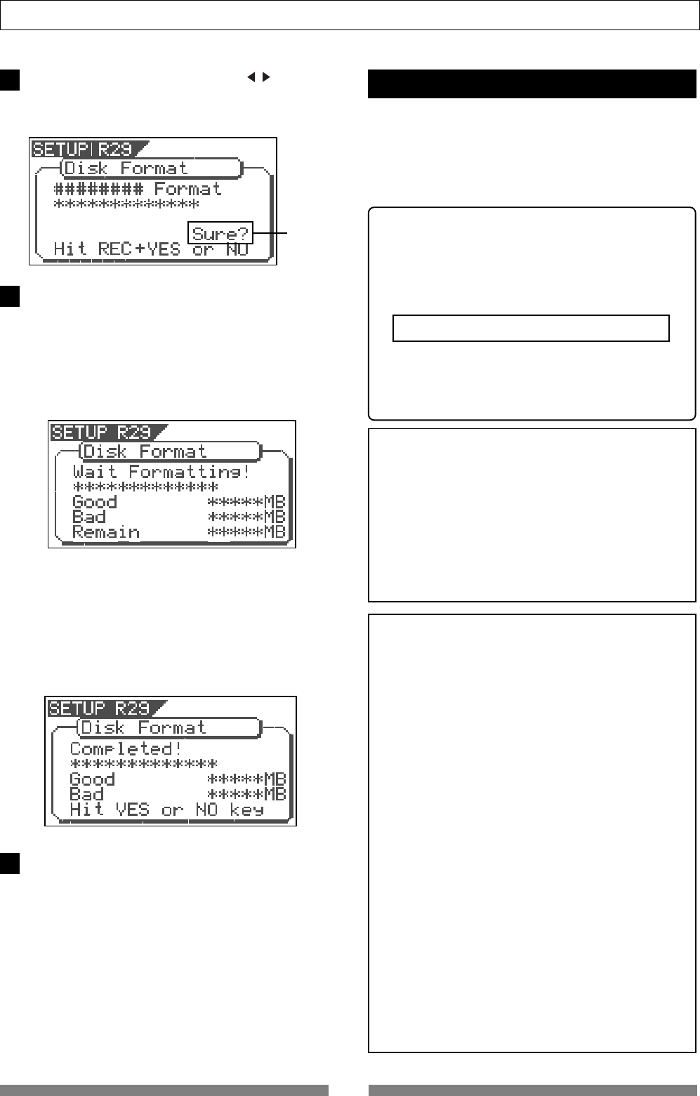
Turn ON the VF80.
Press the [SETUP] key.
The system will go to the SETUP mode.
The select display of the SETUP menu appears. (The
highlight indicates the menu that is currently selected.)
Turn the [JOG] dial to highlight the “Disk Format” menu
title, press the [ENTER/YES] key.
“IDE” indicates the current drive.
Press the [ENTER/YES] key while “IDE” is flashed.
The menu to select the format type appears.
The display will appear as follows, according to the
previous format type. “****” represents the name of the
drive.
The hard disk formatted in the “Standard” type upon
newly formatting the hard disk will show “Standard” and
“Erase”. The hard disk formatted in the “Quick” type
upon newly formatting the hard disk will show
“Standard” and “Quick”. The user can select one.
Flashing
Flashing
The hard disk is formatted with the access time
of the unit sectors, while judging whether the
sectors are good or bad. The formatting time
tends to be longer with this type, however, the
reliability is better.
Therefore, it is recommended that this default
format type is selected under normal
conditions.
This choice is only available when a hard disk
previously formatted in the “Standard” type is
being reformatted. With this format, the
“Standard” type is maintained, while all data on
the hard disk are erased. The formatting time is
shorter than the time required to format a
“Standard” type.
This is a quick formatting procedure in which all
hard disk sectors are considered to be good
sectors. The formatting time is fast, however, the
procedure cannot discover bad sectors.
Therefore, it is recommended that this format type
is only used when formatting a new hard disk that
Fostex has already confirmed to operate
normally.
1
2
3
4
21
About the hard disk storage device
Select the format type with the [CURSOR / ] key. Then
press the [ENTER/YES] key.
The format type selected is set and “Sure?” flashes.
Flashing
Press the [ENTER/YES] key while the [RECORD] key
is depressed.
If the “Standard” format is selected and executed, the
formatting process takes place while showing the
progress of the good sectors (Good ***MB) on the disk,
bad sectors on the disk (Bad ***MB) and remainder
(Remain ***MB).
Nothing can be done during the formatting process.
Please wait for a while until the process is completed.
When the hard disk is successfully formatted
(formatting completed), the number of sectors and
noncontiguous sectors are shown after formatted, then
“Completed!” lights up. Formatting is completed
instantaneously if either “Erase” or “Quick” is selected
and executed.
For this reason, the “Completed!” message lights up
without showing the progress status while formatting
is taking place.
Press the [EXIT/NO] key (or [STOP] key) to escape from
the SETUP mode.
The Normal Screen appears indicating the beginning of
the program (P01) that is automatically created after
formatting the hard disk.
Replacing a hard disk
The user can immediately start recording with the
VF80. Note that the current hard disk can also be
replaced with another model for use with the VF80.
(However, please only use hard disks that Fostex
recommends.)
<Operation Confirmed HD List for the VF80>
The updated information on the operation-
confirmed HD and backup media for VF80 is
mentioned in the following Fostex international
web site.
<http: // www. fostex.co.jp/int/index.htm>
For those who are unable to check our web site,
please contact the Fostex distributor in your
territory.
<Warning>
This section describes the procedures to replace the hard
disk. However, we recommended that the customer ask
the Fostex Customer Service Department to replace the
VF80 hard disk. Note that the product is not warranted
for any malfunctions that may occur after the customer
replaces the hard disk on their own. Also note that Fostex
will not be held liable for any accidents that may occur
during the replacement process or any hard disk
damages, if the customer decides to replace their own
hard disk on their own.
<Precautions Upon Replacement>
• Always turn OFF the power of the VF80 and unplug the
power plug from the electric outlet when replacing the
hard disk.
• Always place the hard disk on a flat and stable platform
during the replacement process. Place a soft cloth
under the unit to protect the product from scratching.
Gloves are recommended to prevent any hand injuries.
<Precautions Upon Handling the Hard Disk>
• A hard disk is an extremely sensitive precision device.
Never expose the hard disk to “
strong shocks
” when
replacing, assembling or handling. Never leave the
hard disk by a device that generates strong magnetic
fields.
• Always set the DIP switch and Jumper of the newly
assembled hard disk to the “
Cable Select
” setting.
The hard disk will not operate normally if the setting
is set to “
Slave
” or “
Master
” when the hard disk is
assembled. Refer to the User’s Manual of the hard disk
for more details on the DIP switch and Jumper settings.
• Note that the connector of some hard disks may be stiff,
and thus make it difficult or impossible to insert or
connect. Never apply excessive force to insert the
connector in such case. Always make a point to gently
insert the connector. Failure to do so may result in
unexpected injuries or damage the hard disk.
5
6
7
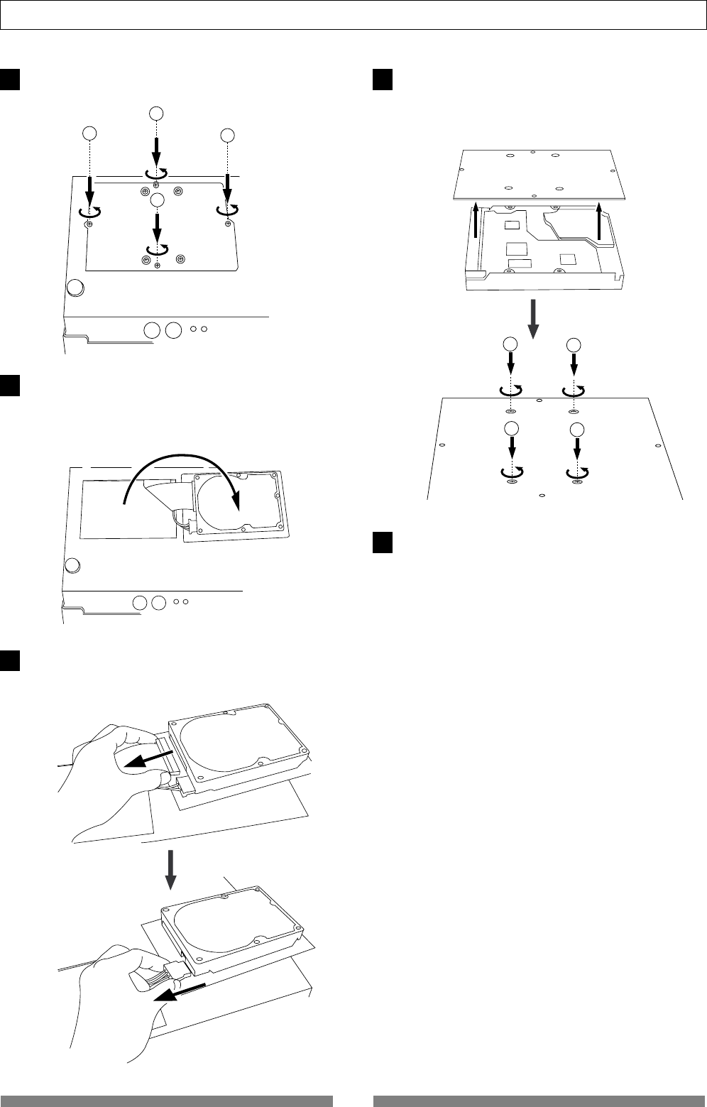
22
About the hard disk storage device
12
34
1
2
4
3
Unscrew the four screws from the bottom of the main
unit that are fixing the panel.
Turn over the panel that the hard disk is fixed according
to the instructions shown in the figure below.
Note that hard disk cables will be connected.
Be careful not to apply excessive force when turning
over the panel.
Remove the two cable connectors that are connected
to the hard disk.
Gently hold the connector and slowly pull out.
After disconnecting the cables, remove the panel that
is fixing the hard disk.
Unscrew the four screws with a screwdriver, as shown
in the Figure.
Fix a new hard disk to the panel in the reverse order of
removing the hard disk as performed earlier. Connect
the cables. Then house the hard disk at the bottom of
the main unit.
Follow the <Precautions> described earlier, and properly
assemble the parts.
When the new hard disk is successfully assembled,
go to the next section. Now, format the unformatted
hard disk.
1
2
3
4
5
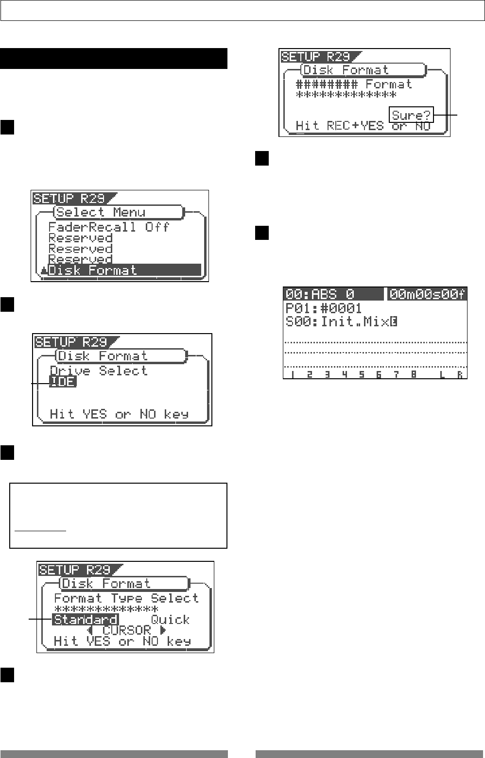
23
About the hard disk storage device
<Normal Screen>
Formatting the Hard disk
Carefully follow the instructions below to newly
format the hard disk properly.
Press the [ENTER/YES] key.
The drive selection display appears.
“IDE” will be flashed.
Press the [ENTER/YES] key where the “IDE” is flashed.
The menu to select the format type appears.
“****” represents the name of the drive.
<CAUTION>
Either the “
Standard
” or “
Quick
” format type can
be selected. However, make sure that the
“Standard”
format type is selected when
formatting a newly installed hard disk.
Press the [ENTER/YES] key where the “Standard” is
flashed.
The format type selected is set and “Sure?” flashes.
Press the [ENTER/YES] key while the [RECORD] key
is depressed.
The formatting process is started. The formatting
process will take some time.
When the formatting is successfully completed,
“Completed!” will light up on the display.
Press the [EXIT/NO] key (or [STOP] key) to escape from
the SETUP mode.
The Normal Screen appears indicating the beginning
of the program (P01) that is automatically created after
formatting the hard disk.
Flashing
Flashing
Flashing
1Turn ON the VF80 after plugging the power cable in the
electric outlet.
The VF80 will startup. “Unformat!” will appear on the
LCD. The menu will automatically go to the SETUP
mode.
The display showing the “Disk Format” menu appears.
2
3
4
5
6
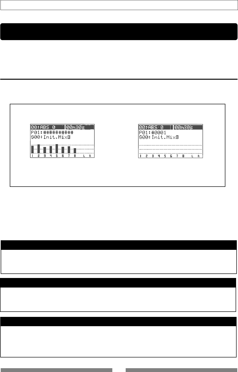
24
Basic Recording/Playback
Basic Recording and Playback
This chapter describes the basics of recording and playback audio using the VF80.
Before carrying out recording/playback, read “About a demonstration song!”, “Connections of exter-
nal equipment”, “Preliminary knowledge” and “LCD”.
About a demonstration song!
Your VF80 may have a demonstration song on program 1 (P01) when shipped (note that some VF80
units may not have a demonstration song, depending on the production). Please check whether a
demonstration song is recorded or not on your unit according the following manner.
If a demonstration song is recorded, you can listen to the song any time by playing back program
1 (see page 28 for details about how to play back a program).
Note that you cannot record a new material on program 1 if a demonstration song is recorded on
program 1. Therefore, before starting recording for the first time, you must carry out any of the
following operations.
Note: You can start recording without the need for carrying out any of the following operations if no
demonstration song is recorded on your unit.
If you wish to start recording while keeping the demonstration song
Create a new program.
The newly created program is not record-prohibited, so you can record a material onto it.
See page “61” for details about how to create a new program.
<To check whether a demonstration song is recorded or not>
After turning on the unit and booting up program 1, press the [PLAY] key to start playback.
• If the level meters move:
A demonstration song is recorded.
Title of the recorded demonstration song will be
indicated for the program title.
• If the level meters do not move:
No demonstration song is recorded.
Temporary title such as "#0001" will be indicated
for the program title.
If you wish to record a material on program 1 (overwriting the demonstration song)
Set "Rec Protect" menu in the setup mode to "Off".
Now you can overwrite the demonstration song on program 1 by a new material.
See page “129” for details about how to make the record-protect setting to "Off".
If you wish to record a material onto program 1 after deleting the demonstration song
Delete program 1.
After deleting program 1, a new blank "program 1" is automatically created onto which you can
record a new material.
See page “62” for details about how to delete a program.
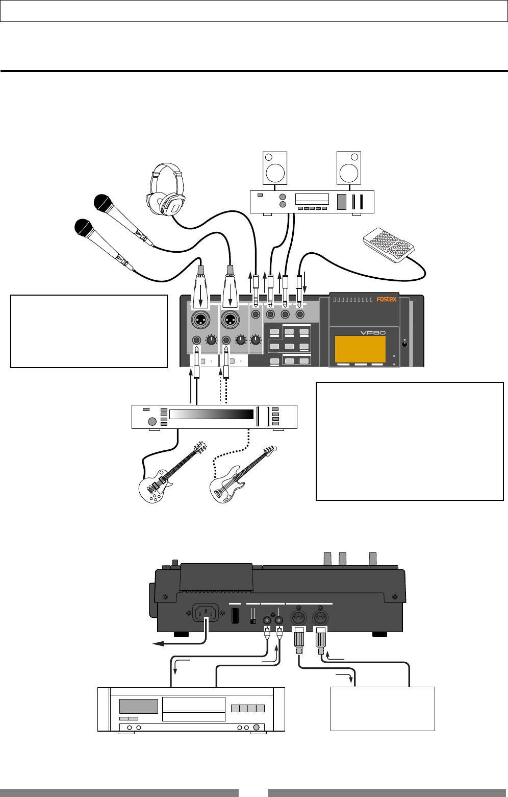
25
Basic Recording/Playback
DIGITAL MULTITRACKER
PHANTOM
ACCESS
PEAK
CH ON/OFF
LR
GUITAR
GUITAR
LINE MIC LINE MIC MIN MAX
MASTERING TRAINING
EFFECTEQPAN
SCENE SEQ.SCENE
TRACK
TRIMTRIM
MIX PARAMETER
PGM FADER MAP
ON/OFF
2TRK MODE
FOOT SW
ST OUT
PHONES
INPUT A
BOUNCE
INPUT B
PEAK
CH ON/OFF
UNBAL UNBAL
BAL
BAL
F1 F2 F3
EDIT
REC EFF
OFF
ON
MIDI
OUTPUT INPUT OUTPUT
INPUT
POWER PHANTOM S/P DIF / DATA
Rear panel
Foot switch (mode 8051)
Amplifier + Speakers etc.
Microphones (Dynamic
or condenser type)
Headphones
Guitar processor
Electric bass
Electric guitar
Digital equipment (CD, MD, DAT etc.)
AC outlet
Sequencer
PC w/sequence software
Top panel
Connections of external equipment
You can connect various sound sources and external devices to the input and output connectors of the
VF80 as shown in the example below. When making connection, make sure that the [MASTER] fader
is set to the lowest (“∞”) position and the [PHONES] knob to the left most (“MIN”) position. Otherwise,
your speakers or headphones may damage by the audio noise generated when connecting cables.
<Note>
You cannot use both the
[BAL]
and
[UNBAL]
connectors on INPUT A and
INPUT B simultaneously. Plugging the
[UNBAL]
connector disconnects the
[BAL]
connector.
<Note>
Do not power on the machine with non-speci-
fied foot SW connected to the foot SW jack.
When powering on the machine with non-
specified foot SW (latch type foot SW, etc.)
connected to the foot SW jack, there is a case
that the machine does not correctly boot up
with “
No Drive!
” alert message. In such a case,
power off the machine once, disconnect the
foot SW and then power back on.
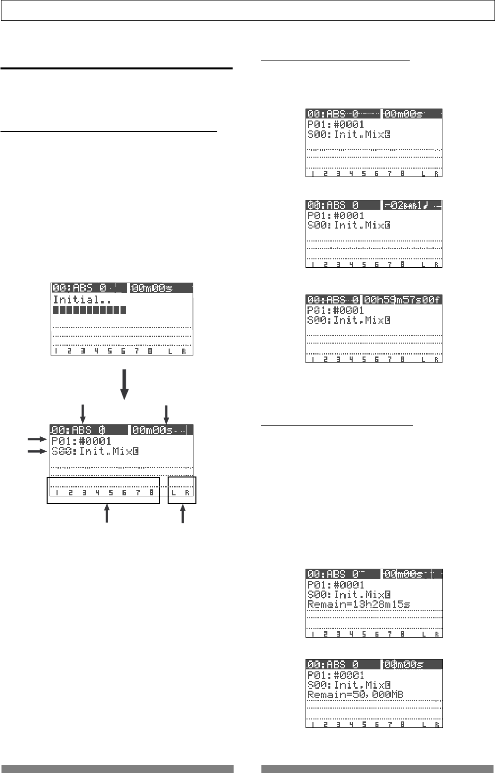
26
Basic Recording/Playback
Normal screen
Normal screen with BAR/BEAT/CLK time base
Normal screen with MTC time base
Screen example while starting up
Remaining time displayed in time
Remaining time displayed in MB
1
2
34
65
Normal screen with ABS time base
LCD
This section describes major contents on the LCD
display and their operations.
Display when turning on the power
When turning on the power of the VF80 on which a
formatted hard disk is installed, the unit starts up and
“Initial..” and “version number” appears on the LCD
display, followed by “Current Dr”, “IDE”, “hard disk name
(momentarily)” and “record mode (Standard or
Quick)”. Then the unit gets ready at the beginning
(ABS 0) of the program which was selected when the
power was turned off last time. The current position
is shown by the time base previously selected.
The display that appears when the unit gets ready is
call “Normal screen”. The Normal screen shows the fol-
lowing items.
1. Scene number & name
With the initial setting, “S00: Initial Mix” appears.
2. Program number & name
With the initial setting, “P01: #0001” (#0001 is a tentative
name) appears.
3. Mark number & name
With the initial setting, “00: ABS 0” appears, showing that
the current location is at the beginning of the program. When
the recorder starts running, “:” between the number and
name is replaced with “+”.
4. Time base
With the initial setting, the ABS time base is selected.
You can change the time base by using the [TIME BASE SEL]
key (see the next section).
5. Level meters for Tracks 1 through 8
6. Master level meters for the Stereo output (L, R)
Switching the time base
Each press of the [TIME BASE SEL] key cycles the time
base of the Normal screen between “ABS”, “BAR/BEAT/
CLK” and “MTC”.
“Disk remain” indication
You can check the disk remaining space which shows
the “recordable space left on the current disk”.
The disk remaining space (REM) is shown during “Rec
ready” or “Recording”, in “time” when the remaining
time is less than 100 hours, or in “MB (Megabyte)” of
the remaining space when it exceeds 100 hours.
Note that the remaining time is shown as the record-
able time when you record onto a single track.
You can calculate the recordable time for recording
onto 8 tracks by dividing the displayed remaining time
by 8.
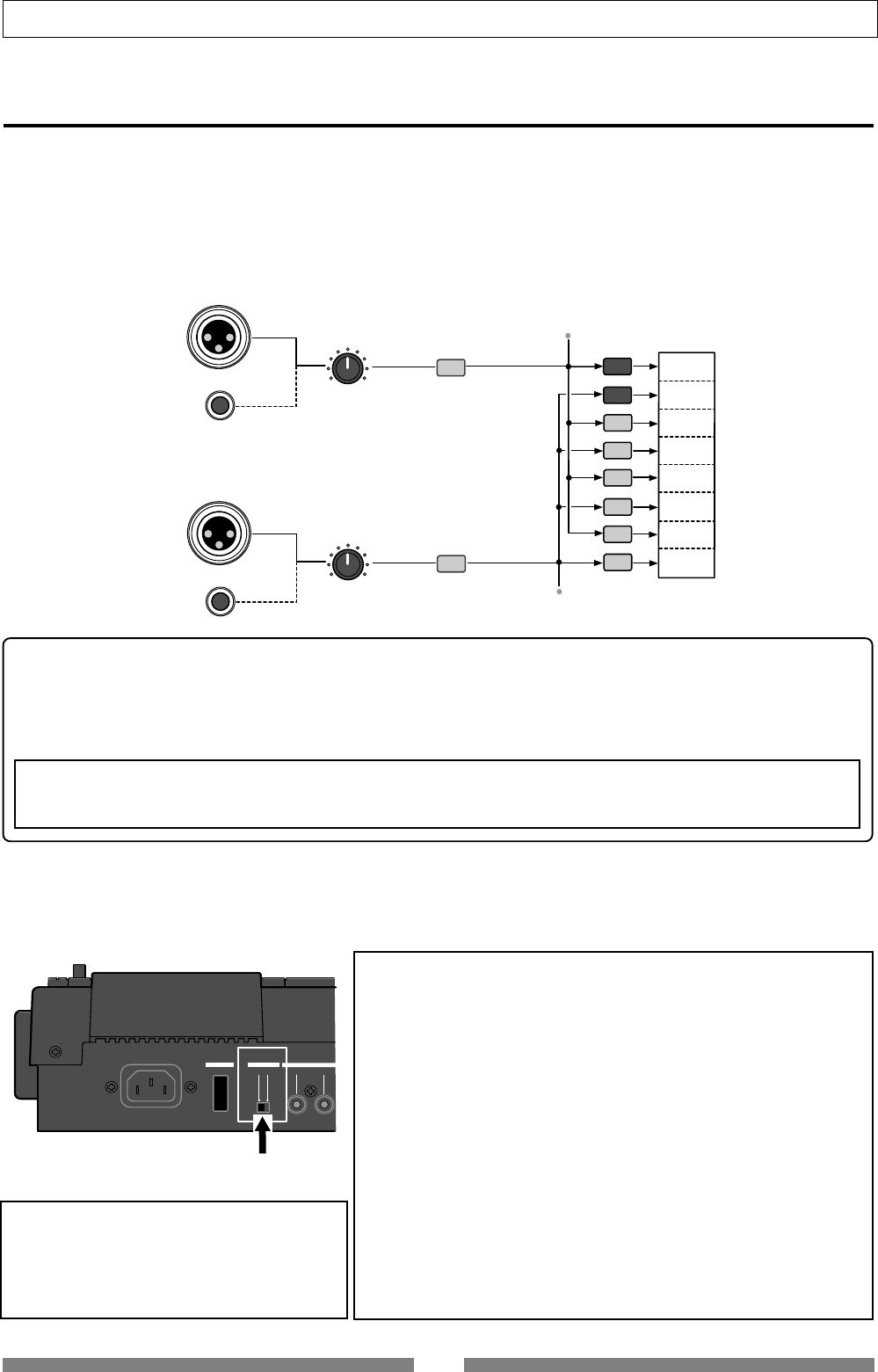
27
Basic Recording/Playback
BALANCE
UNBALANCE
TRIM
PEAK
CH ON/OFF
BALANCE
UNBALANCE
TRIM
PEAK
CH ON/OFF
TRACK 1
TRACK 2
TRACK 3
TRACK 4
TRACK 5
TRACK 6
TRACK 7
TRACK 8
TRACK STATUS
/ TRACK SEL HARD DISK
INPUT A
INPUT B
OFF
ON OUTPUT INPUT
POWER PHANTOM S/P DIF / DATA
[PHANTOM] switch
Preliminary knowledge
• Inputs and tracks
You can record onto adjacent two tracks (Tracks 1-2, 3-4, 5-6, or 7-8) or a mono track (one of Tracks 1 through
6). You cannot select another combination.
The input signal from INPUT A is fed to odd tracks (1, 3, 5 and 7), while the input signal from INPUT B is fed to
even tracks (2, 4, 6 and 8). Because each input signal is directly fed to appropriate tracks, you cannot tailor the
signal when recording. However, you can add reverb or equalize the sound during mixdown, or rerecord a track
sound later with applying a distortion-type effect.
<Balanced (XLR) and unbalanced (phone) input connectors>
Both the balanced and unbalanced input connectors are provided for INPUT A and INPUT B, allowing connec-
tion of balanced and unbalanced devices. In addition, the phantom (DC 48 V) power can be supplied to the
balanced XLR inputs, so you can use condenser microphones that need the phantom power (see the following
section about how to use condenser microphones).
<Note>
You cannot use both the balanced and unbalanced inputs simultaneously.
When plugging the unbalanced (phone) input connector, the balanced (XLR) input connector is disconnected.
• How to use condenser microphones
When connecting a condenser microphone that needs the phantom power, set the [PHANTOM] switch on the rear
panel to “ON”. Read the following notes carefully before using the phantom power.
<Notes for using the phantom power>
• Be sure to keep the following notes.
* When connecting a condenser microphone to the balanced input
connector of the VF80, check whether or not the microphone needs
the phantom power (+48 V).
* Switch the
[PHANTOM]
switch to ON after connecting a microphone.
* When switching the
[PHANTOM]
switch, or when plugging or
unplugging a microphone, mute the VF80 output signals.
* When connecting a dynamic microphone to the balanced input
connector, set the
[PHANTOM]
switch to OFF. Otherwise, the
microphone may damage.
• You cannot use the phantom power for following microphones.
* microphones with the unbalanced output
* high impedance microphones
* microphones with the XLR connectors that leaks a signal between
pin #2 and pin #1 or pin #3 and pin #1
* microphones with the center tapout type ground such as old-
fashioned ribbon microphones
<Important notes for on/off switching>
Note that the VF80 power must be ON when
changing the
[PHANTOM]
switch setting.
Also note that the
[PHANTOM]
switch should be
set to “
OFF
” after using the phantom power.
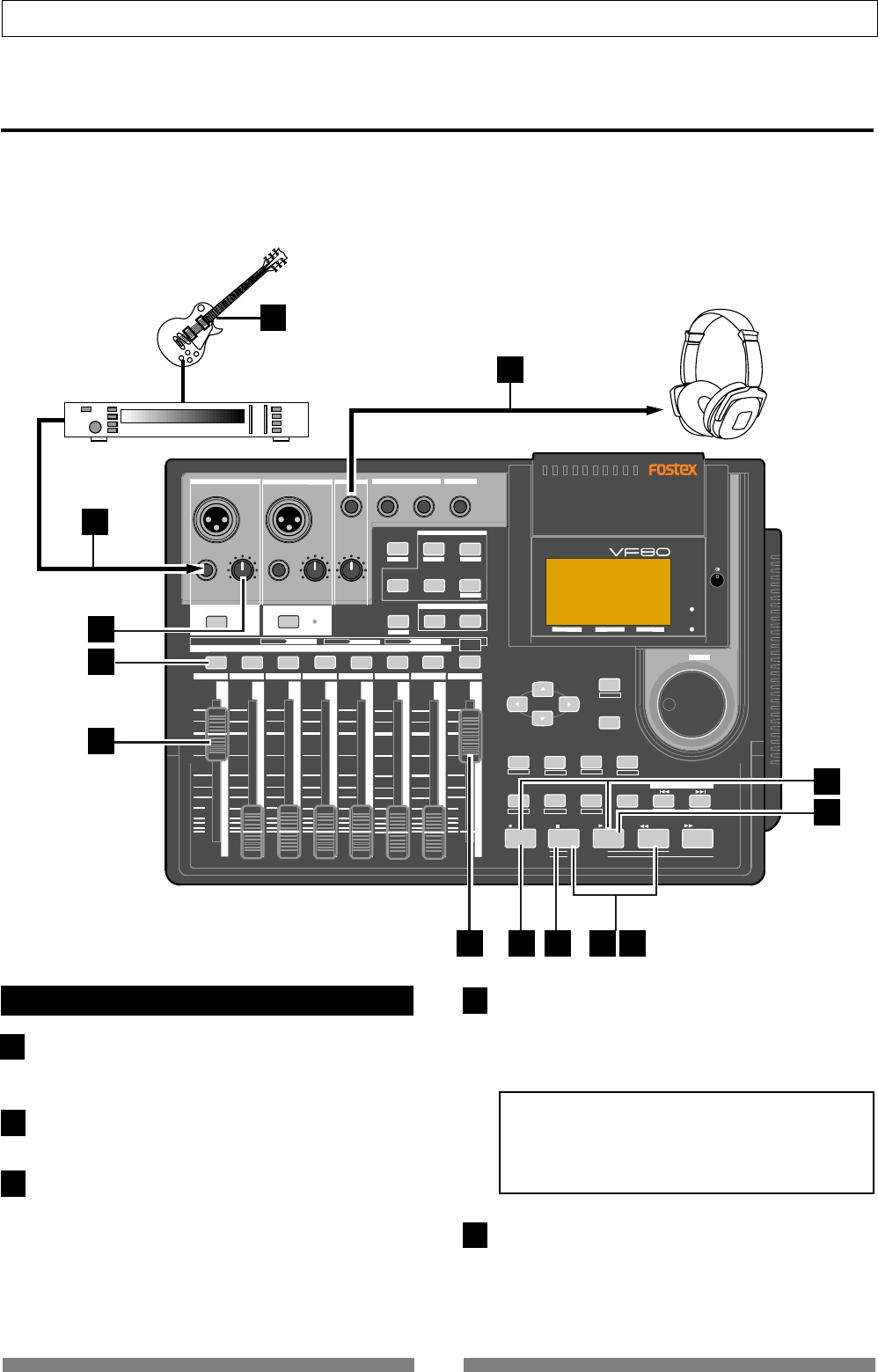
28
Basic Recording/Playback
1
2
3
4
5
DIGITAL MULTITRACKER
LOCATE ABS 0
LOCATE REC END
SEL
TIMEBASE
CURSOR
PHANTOM
ACCESS
PEAK
CH ON/OFF
LR
GUITAR
GUITAR
LINE MIC LINE MIC MIN MAX
MASTERING TRAINING
EFFECTEQPAN
SCENE SEQ.SCENE
TRACK
UNDO
SETUP
PUNCH
AUTO LOOP PITCH SCRUB
VARI
F FWDREWINDPLAYSTOPRECORD
EXIT
ENTER
TRIMTRIM
WAVE FORM
MIX PARAMETER
PGM FADER MAP
ON/OFF
2TRK MODE
F1 F2 F3 SHIFT
EDIT EDIT EDIT MARK DELETE
LOCATE
FOOT SW
ST OUT
PHONES
INPUT A
BOUNCE
INPUT B
+6
-10
-20
-40
-
∞
-30
0
+6
-10
-20
-40
-
∞
-30
0
+6
-10
-20
-40
-
∞
-30
0
+6
-10
-20
-40
-
∞
-30
0
+6
-10
-20
-40
-
∞
-30
0
+6
-10
-20
-40
-
∞
-30
0
+6
-10
-20
-40
-
∞
-30
0
+6
-10
-20
-40
-
∞
-30
0
PEAK
CH ON/OFF
2345 6 7/8 2TRK1 MASTER
TRACK STATUS / TRACK SEL
TRACK STATUS RED REC GREEN PLAY OFF MUTE STATUS
/SEL
EJECT
/YES
/NO
SHUTTLE
JOG
UNBAL UNBAL
BAL
BAL
F1 F2 F3
EDIT
/REDO
REC EFF
2
1
6
3
4
4 5 9 7 10
8
11
6
Basic recording (recording onto a single track)
At first, let’s record a single sound source onto a single track to know the basic recording procedure of the VF80
There are 8 recording tracks (Tracks 1 through 8) and you can record onto any desired track(s).
In the following example, we are going to record an electric guitar (with an effect unit) onto Track 1.
Before starting, set all the track faders (1 through 6 and 7-8) and the master fader to the lowest position (-∞), and
the [TRIM] knob to the left most position (LINE).
Preparation for recording
Connect the [INPUT A] UNBAL jack to the output of the
effect unit whose input is connected to a guitar.
To record onto Track 1, 3, 5 or 7, use INPUT A.
Connect the [PHONES] jack to headphones for moni-
toring.
Press the [TRACK STATUS/TRACK SEL] key of Track
1.
The key lighting in green changes to flashing in red,
showing Track 1 is now armed. (The “Remain” time is
shown on the screen.)
The [CH ON/OFF] key of INPUT A automatically lights.
In this condition, by pressing the [CH ON/OFF] key of IN-
PUT A, INPUT A can be muted.
Raise both the track 1 fader and master fader to “0” po-
sition.
This is preparation for monitoring sound. If both of
these faders are set at the minimum position, no sound
can be monitored.
<Note>
The track 1 fader can be used for adjusting the moni-
tor level without affecting the recording level. To
adjust the recording level, use the
[TRIM]
knob of
INPUT A.
Press the [RECORD] key.
The key starts flashing in red, while Track 1 (which is
armed) changes to the input monitor mode.
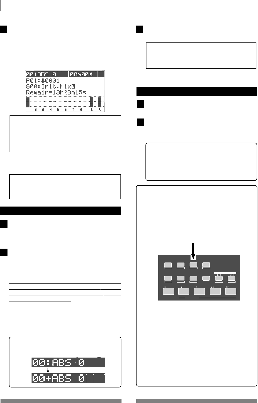
29
Basic Recording/Playback
6
7
8
9
10
11
LOCATE ABS 0
LOCATE REC END
SEL
TIMEBASE UNDO / REDO
SETUP
PUNCH I/O
AUTO LOOP PITCH SCRUB
VARI
F FWDREWINDPLAYSTOPRECORD
WAVE FORM
F1 F2 F3 SHIFT
EDIT EDIT EDIT MARK DELETE
LOCATE
[UNDO/REDO] key
Use the [TRIM] knob of INPUT A while playing the gui-
tar to get proper gain.
Set the gain at maximum within the range in which the
[PEAK] indicator does not turn on when playing the
guitar at the loudest volume.
You can monitor both the input level of Track 1 and the
stereo (L & R) output level from the bar-graph meters
on the screen.
<Note>
Set the gain not to light the
[PEAK]
indicator when
playing the guitar at the loudest volume.
When the
[PEAK]
indicator lights, the input level is
too high and the sound may be distorted or digital
noise may be generated.
In the condition above, if you turn the [PHONES] knob
clockwise, you can monitor the sound from the head-
phones.
<Warning!>
Be careful not to excessively raise the
[PHONE]
volume.
Prolonged exposure to loud sounds may have an
adverse effect on hearing.
Recording
Press the [REWIND] key while holding down the [STOP]
key to locate “ABS 0”.
If the current recorder position is “ABS 0”, you can skip
the operation above.
Press the [PLAY] key while holding down the [RECORD]
key to start recording.
The [TRACK STATUS/TRACK SEL] key of Track 1 and the
[RECORD] key light on, showing the VF80 is now record-
ing.
The VF80 uses the direct recording method. In this
method, a digital signal just after the A/D conversion is
directly recorded onto a track, without being routed to
extra algorithms such as EQ.
You can add reverb or equalize the sound during
mixdown.
In addition, the insert effect function allows rerecord-
ing a track sound with applying a distortion-type effect
later. See “using the insert effect” on page 83.
When the recorder starts running, the mark number and name
shown on the top line of the screen changes as below, showing
that the current position is ahead of “ABS 0” point.
To stop recording, press the [STOP] key.
After showing “Please Wait!”, the LCD returns to the Nor-
mal screen.
<Unarming a track>
To unarm a track, press the flashing [TRACK STA-
TUS/TRACK SEL] key twice. The key changes to light
in green.
Now you have recorded a sound source onto a track.
Playback
Press the [REWIND] key while holding down the [STOP]
key to locate “ABS 0”.
Press the [PLAY] key to start playback.
You can control the playback level by the track 1 fader.
If you find that the recording was not successfully made,
use the undo/redo function and try recording again.
<Track muting >
The playback level of each recorded track can be con-
trolled using the corresponding track fader.
You can mute the playback track by pressing the cor-
responding [TRACK STATUS/TRACK SEL] key except
in the mix parameter edit mode.
Undo/Redo
After finishing a recording, pressing the [UNDO/
REDO] key returns to the condition just before re-
cording (Undo).
If you press the [UNDO/REDO] key again, you can
cancel the Undo operation and return back to the
condition after recording.
<Note>
The undo/redo function is available to any recording,
however, if you carry out any of the following operations
after recording, you cannot use the undo/redo function.
Therefore, if you are not satisfied with the recording,
press the
[UNDO/REDO]
key immediately to undo the
recording and make recording again.
* Making a new recording
* Making a new editing (copy, move, erase, auto punch
in/out, etc.)
* Turning off the power
* Executing program select, rename, and deleting
* Executing drive selection
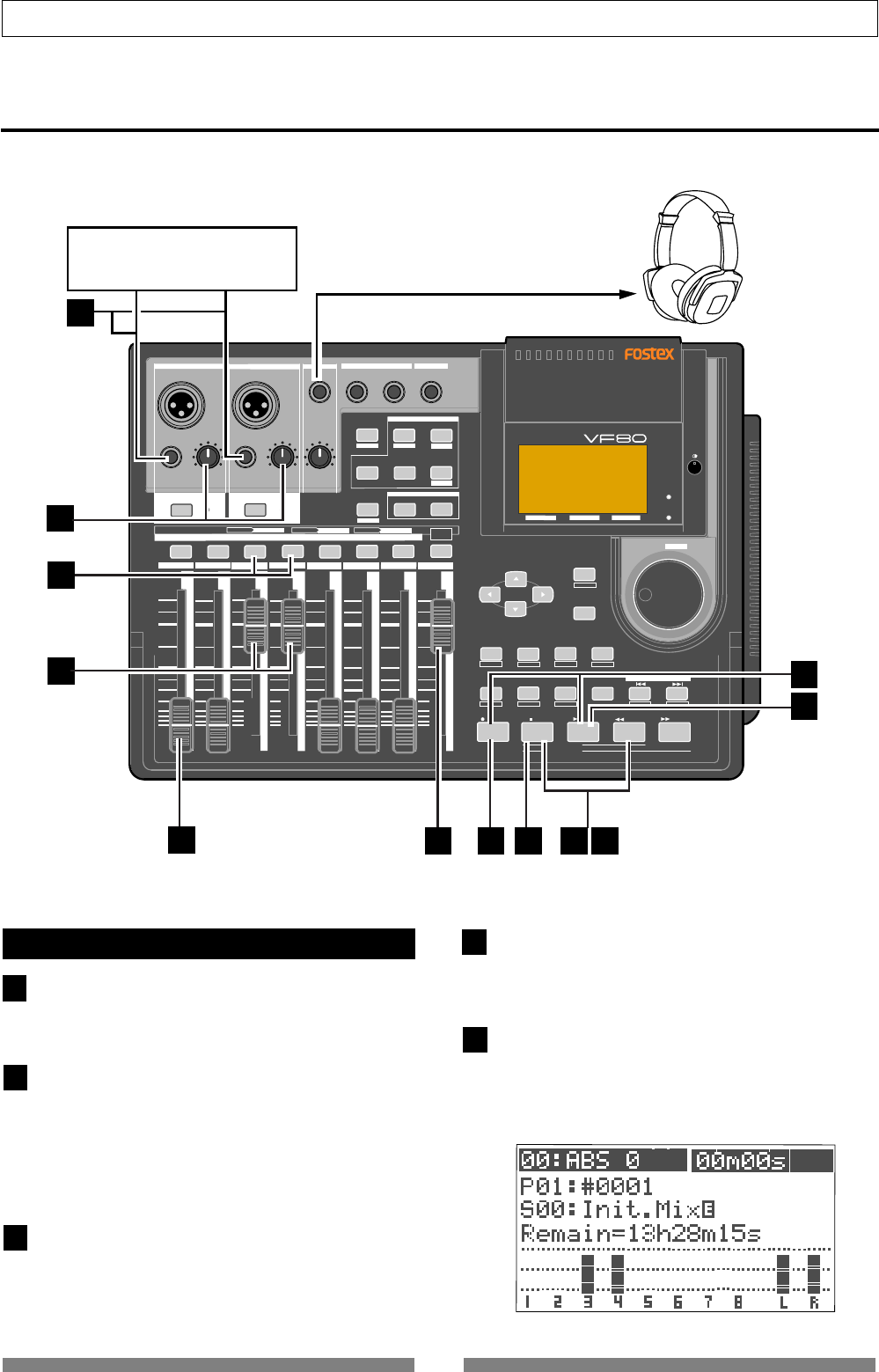
30
Basic Recording/Playback
DIGITAL MULTITRACKER
LOCATE ABS 0
LOCATE REC END
SEL
TIMEBASE
CURSOR
PHANTOM
ACCESS
PEAK
CH ON/OFF
LR
GUITAR
GUITAR
LINE MIC LINE MIC MIN MAX
MASTERING TRAINING
EFFECTEQPAN
SCENE SEQ.SCENE
TRACK
UNDO
SETUP
PUNCH
AUTO LOOP PITCH SCRUB
VARI
F FWDREWINDPLAYSTOPRECORD
EXIT
ENTER
TRIMTRIM
WAVE FORM
MIX PARAMETER
PGM FADER MAP
ON/OFF
2TRK MODE
F1 F2 F3 SHIFT
EDIT EDIT EDIT MARK DELETE
LOCATE
FOOT SW
ST OUT
PHONES
INPUT A
BOUNCE
INPUT B
+6
-10
-20
-40
-
∞
-30
0
+6
-10
-20
-40
-
∞
-30
0
+6
-10
-20
-40
-
∞
-30
0
+6
-10
-20
-40
-
∞
-30
0
+6
-10
-20
-40
-
∞
-30
0
+6
-10
-20
-40
-
∞
-30
0
+6
-10
-20
-40
-
∞
-30
0
+6
-10
-20
-40
-
∞
-30
0
PEAK
CH ON/OFF
2345 6 7/8 2TRK1 MASTER
TRACK STATUS / TRACK SEL
TRACK STATUS
RED REC GREEN PLAY OFF MUTE STATUS
/SEL
EJECT
/YES
/NO
SHUTTLE
JOG
UNBAL UNBAL
BAL
BAL
F1 F2 F3
EDIT
/REDO
REC EFF
1
5
2
3
3 4 8 6 9
7
10
7
1
2
3
4
5
Stereo source
Basic recording (recording onto two tracks)
After recording onto track 1 as described in the previous section, let’s make recording of a stereo sound source
onto tracks 3 and 4.
Preparation for recording
Connect the [INPUT A] UNBAL and [INPUT B] UNBAL
jacks to the L and R outputs of the stereo source re-
spectively.
Press the [TRACK STATUS/TRACK SEL] keys of Tracks
3 and 4.
The keys lighting in green change to flashing in red,
showing Tracks 3 and 4 are now armed. (The “Remain”
time is shown on the screen.)
The [CH ON/OFF] keys of INPUT A and B automatically
light in green.
Raise the faders of tracks 3 and 4 and [MASTER] fader
to “0” position.
This is preparation for monitoring sound. If both of
these faders are set at the minimum position, no sound
can be monitored.
Press the [RECORD] key.
The [RECORD] key starts flashing in red, while Tracks 3
and 4 (which are armed) changes to the input monitor
mode.
Use the [TRIM] knobs of INPUT A and B while playing
the stereo source to get proper gain.
Set the gain at maximum within the range in which the
[PEAK] indicator does not turn on.
You can monitor both the input level of Tracks 3 and 4
from the bar-graph meters on the screen.
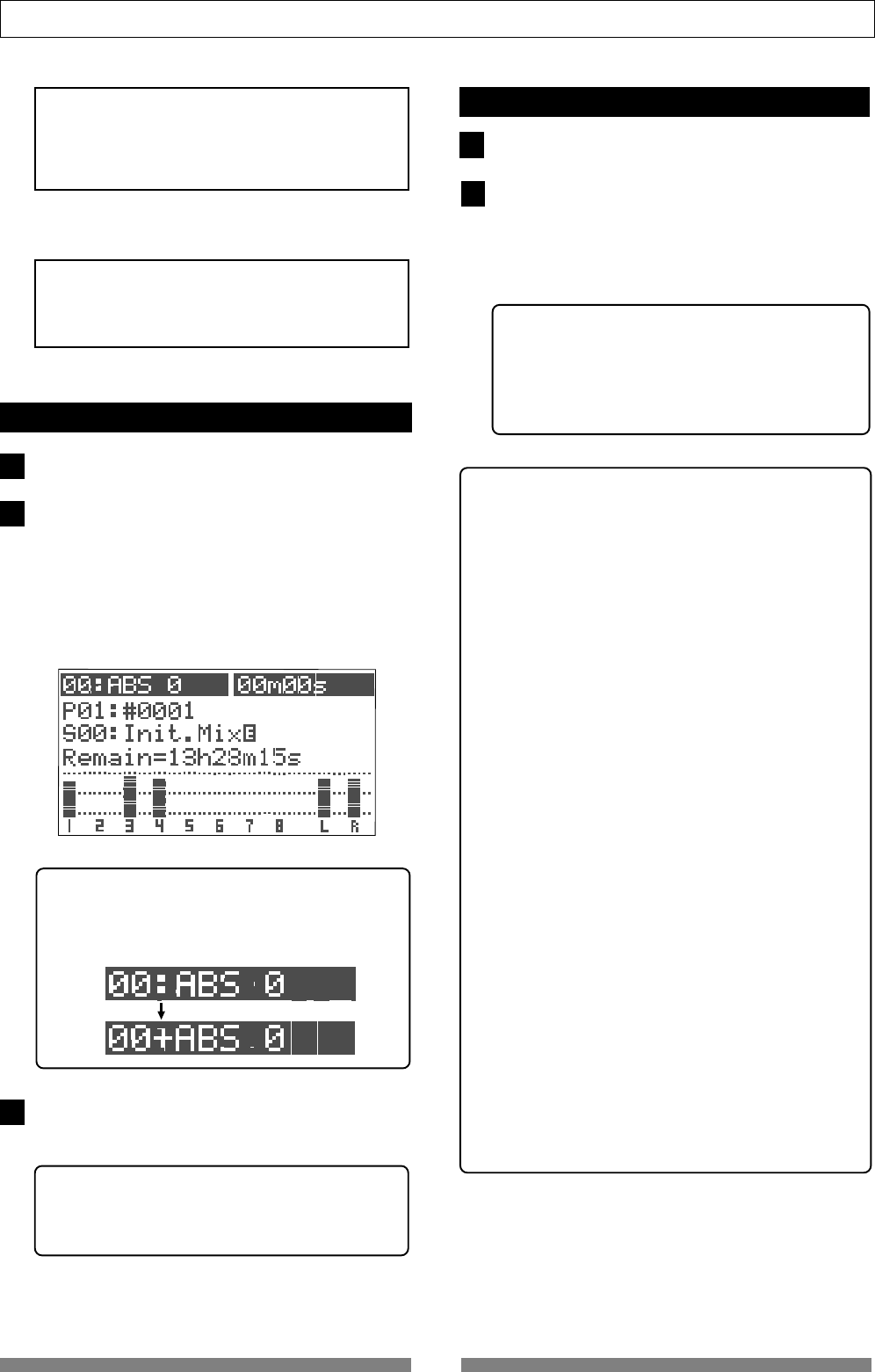
31
Basic Recording/Playback
6
7
8
9
10
<Note>
Set the gain not to light the
[PEAK]
indicator.
When the
[PEAK]
indicator lights, the input level is
too high and the sound may be distorted or digital
noise may be generated.
In the condition above, if you turn the [PHONES] knob
clockwise, you can monitor the sound from the head-
phones.
<Warning!>
Be careful not to excessively raise the
[PHONE]
vol-
ume. Prolonged exposure to loud sounds may have
an adverse effect on hearing.
Recording
Locate the start position (time) for recording.
Press the [PLAY] key while holding down the [RECORD]
key to start recording.
The [TRACK STATUS/TRACK SEL] keys of Tracks 3 and 4,
as well as the [RECORD] key light on, showing the VF80
is now recording.
You can see the meter for Track 1 also moving. By rais-
ing the Track 1 fader, you can make overdubbing onto
tracks 3 and 4 while listening to playback of track 1.
When the recorder starts running, the mark number
and name shown on the top line of the screen changes
as below, showing that the current position is ahead
of “ABS 0” point.
To stop recording, press the [STOP] key.
After showing “Please Wait!”, the LCD returns to the Nor-
mal screen.
<Unarming tracks>
To unarm tracks now recorded, press the flashing
[TRACK STATUS/TRACK SEL] keys again. The keys
changes to light in green.
Now you have recorded a stereo source onto two tracks
(3 and 4).
Playback
Locate the desired position (time) for playback.
Press the [PLAY] key to start playback.
You can control track playback levels by using the cor-
responding track faders.
If you find that the recording was not successfully made,
use the undo/redo function and try recording again.
<Track muting>
The playback level of each recorded track can be con-
trolled using the corresponding track fader.
You can mute the playback tracks by pressing the
corresponding [TRACK STATUS/TRACK SEL] keys
except in the mix parameter edit mode.
<How to use recording tracks effectively>
The VF80 has 8 recordable tracks.
If you record materials onto all 8 tracks according
to the procedures described in “Basic recording”,
you cannot record further materials.
To record more materials, you can use the “track
bounce” technique to save tracks as follows:
1. Record materials onto tracks 1 through 6.
2. Mix the signals recorded on tracks 1 through
6 and record the mixed signal onto tracks 7 and
8.
Then tracks 1 through 6 can be used to record
other materials.
This is the basic technique used for Multitrackers.
We recommend that tracks 7 and 8 are basically
used as the destination tracks of “track bounce”
from tracks 1 through 6.
See “Advanced Operation” for details about the track
bounce technique.
In addition, tracks 7 and 8 play an important role
in “training mode” and “mastering mode” described
later in “Advanced functions”.
The VF80 also provides the “track exchange” func-
tion which allows you to keep recordable tracks.
The VF80 has 16 additional tracks for each pro-
gram, in addition to 8 recordable (and playable)
real tracks (1 through 8). The “track exchange”
function allows you to exchange a real track and
an additional track, making the real track empty.
See page 56 “Recorder functions.”
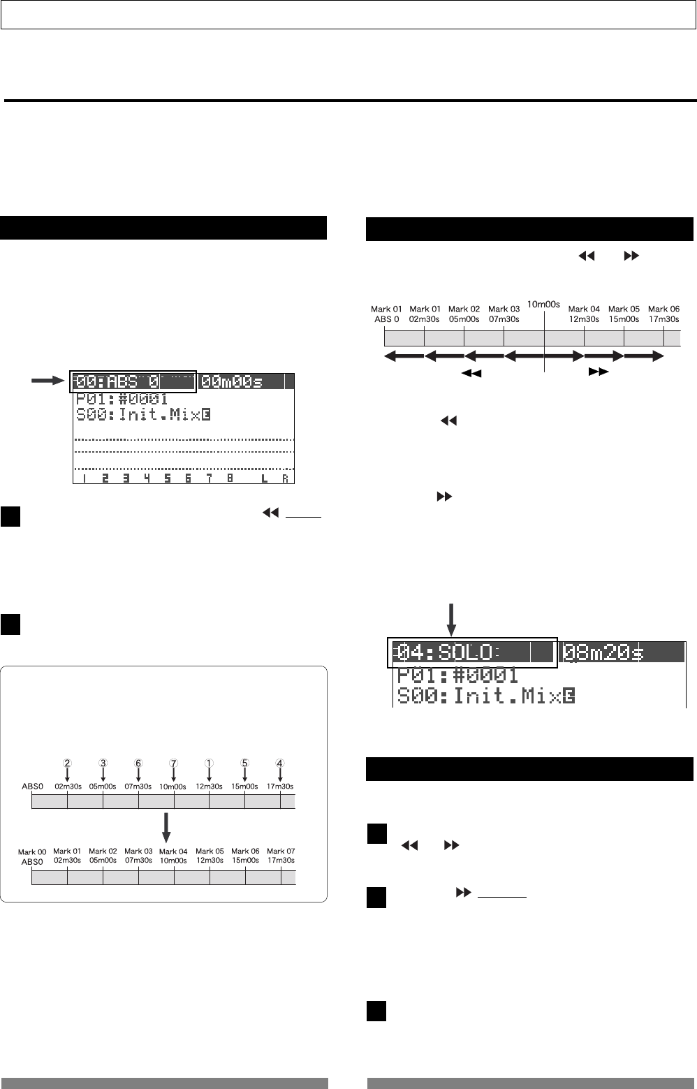
32
Basic Recording/Playback
1
2
[ I] key
[I ] key
1
2
3
Mark function
The VF80 has the Mark function which allows you to set marks at the desired positions in a song.
You can locate a mark position immediately, as well as use mark positions for the punch in and out points, beginning
and end points for repeat and editing points for track editing such as copy, move, erase, etc.
This section describes how to set, delete and locate a mark. For details about editing a mark, see “Recorder func-
tions” described later.
Setting a mark on the fly
In the initial condition, Mark 00 is automatically en-
tered at the beginning of the current program (ABS
0) and named “ABS 0”.
You can enter up to 99 marks (Mark 01 through 99).
Mark number and name are shown on the Normal
screen as the arrow points in the screen example be-
low. (You cannot edit or delete Mark 00.)
During playback (or while stopped), press [| / MARK]
key while holding down the [SHIFT] key.
“Entry Mark” is shown briefly and a mark is entered at
the current position.
Also the time marked is entered in the mark map list
(see “Recorder functions” for details).
To enter another mark, repeat step 1) above.
<Note>
Marks are assigned in ascending order of ABS time.
For example, even if you enter marks in order as shown
in the upper diagram below, the mark numbers are as-
signed as shown in the lower diagram.
Locating a mark
• Pressing [| ] key locates the previous mark.
In the example above, each time you press the key from
the current position, the recorder will locate Mark 03 ->
02 -> 01 -> 00.
• Pressing [ |] key locates the next mark.
In the example above, each time you press the key from
the current position, the recorder will locate Mark 04 ->
05 -> 06.
The current (located) mark number is shown on the
Normal screen.
Deleting a mark
You can delete unnecessary mark
While stopped, locate the mark to be deleted using the
[| ] or [ |] key.
The mark to be deleted is shown on the screen.
Press the [ |/DELETE] key while holding down the
[SHIFT] key.
A pop-up panel asking for confirmation to delete the
current mark appears, in which “Sure?” blinks.
To cancel the operation for deletion, press the [EXIT/
NO] key.
Press the [ENTER/YES] key while holding down the
[RECORD] key.
The current mark is deleted.
You can locate a mark using the [| ] or [ |] key.
Current position
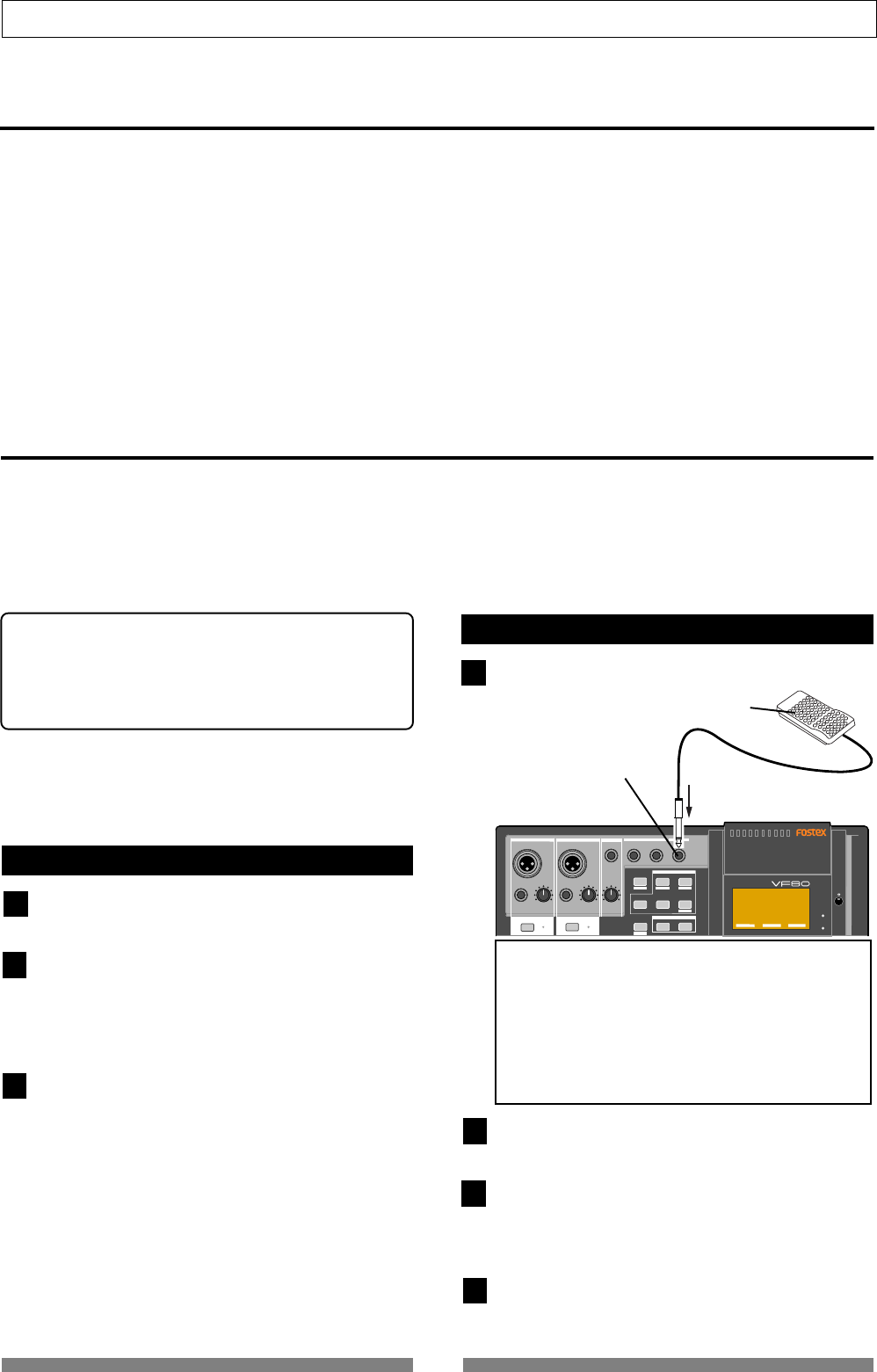
33
Basic Recording/Playback
DIGITAL MULTITRACKER
PHANTOM
ACCESS
PEAK
CH ON/OFF
LR
GUITAR
GUITAR
LINE MIC LINE MIC MIN MAX
MASTERING TRAINING
EFFECTEQPAN
SCENE SEQ.SCENE
TRACK
TRIMTRIM
MIX PARAMETER
PGM FADER MAP
ON/OFF
2TRK MODE
FOOT SW
ST OUT
PHONES
INPUT A
BOUNCE
INPUT B
PEAK
CH ON/OFF
UNBAL UNBAL
BAL
BAL
F1 F2 F3
EDIT
REC EFF
1
2
3
1
2
3
[FOOT SW] jack
FOOT SW (Model 8051)
4
ABS locate functions
There are four types of the ABS locate functions as below.
• Pressing the [REWIND] key while holding down the [STOP] key locates the beginning of the current program
(ABS 00), regardless of the time base setting.
• Pressing the [F FWD] key while holding down the [STOP] key locates the end position of the last recording of the
current program (REC END).
You can use this function to locate the end point of a song or to check the length of a song.
• Pressing the [PLAY] key while holding down the [STOP] key locates the beginning of the last playback.
• Pressing the [RECORD] key while holding down the [STOP] key locates the beginning of the last recording.
Punch in/out
If you are not satisfied with your recording and want to modify only a specific part, you can replace the part with
a new recording using the punch in/out technique.
“Punch in” switches the transport mode from playback to recording, while “Punch out” switches the transport
mode from recording to playback. The point at which a punch in is carried out is called a “punch in point”, while
the point at which a punch out is carried out is called a “punch out point.”
You can carry out the punch in/out operation in 3 ways:
* Manual punch in/out using the keys on the unit
* Using the foot switch (Model 8051)
* Auto punch in/out function
After setting the punch in and out points, the punch
in/out can be took place automatically.
The following description is assumed that the track(s)
to be punched in/out are armed and the source input
level is set appropriately by using the [TRIM] knob.
Manual punch in/out using the keys on the unit
Start playback by pressing the [PLAY] key from a po-
sition before the punch in point.
When the playback position reaches the punch in point,
press the [RECORD] key while holding down the [PLAY]
key.
Only the armed track(s) switch from playback to record-
ing.
At the punch out point, press the [PLAY] key .
The armed track(s) switch from recording to playback.
Punch in/out using the foot switch
Connect the Model 8051 foot switch to the [FOOT SW]
jack.
Start playback by pressing the [PLAY] key from a po-
sition before the punch in point.
When the playback position reaches the punch in point,
step on the foot switch.
Only the armed track(s) switch from playback to record-
ing.
At the punch out point, step on the foot switch.
The armed track(s) switch from recording to playback.
<Note>
Do not power on the machine with non-specified foot
SW connected to the foot SW jack.
When powering on the machine with non-specified
foot SW (latch type foot SW, etc.) connected to the
foot SW jack, there is a case that the machine does
not correctly boot up with “No Drive!” alert message.
In such a case, power off the machine once, discon-
nect the foot SW and then power back on.
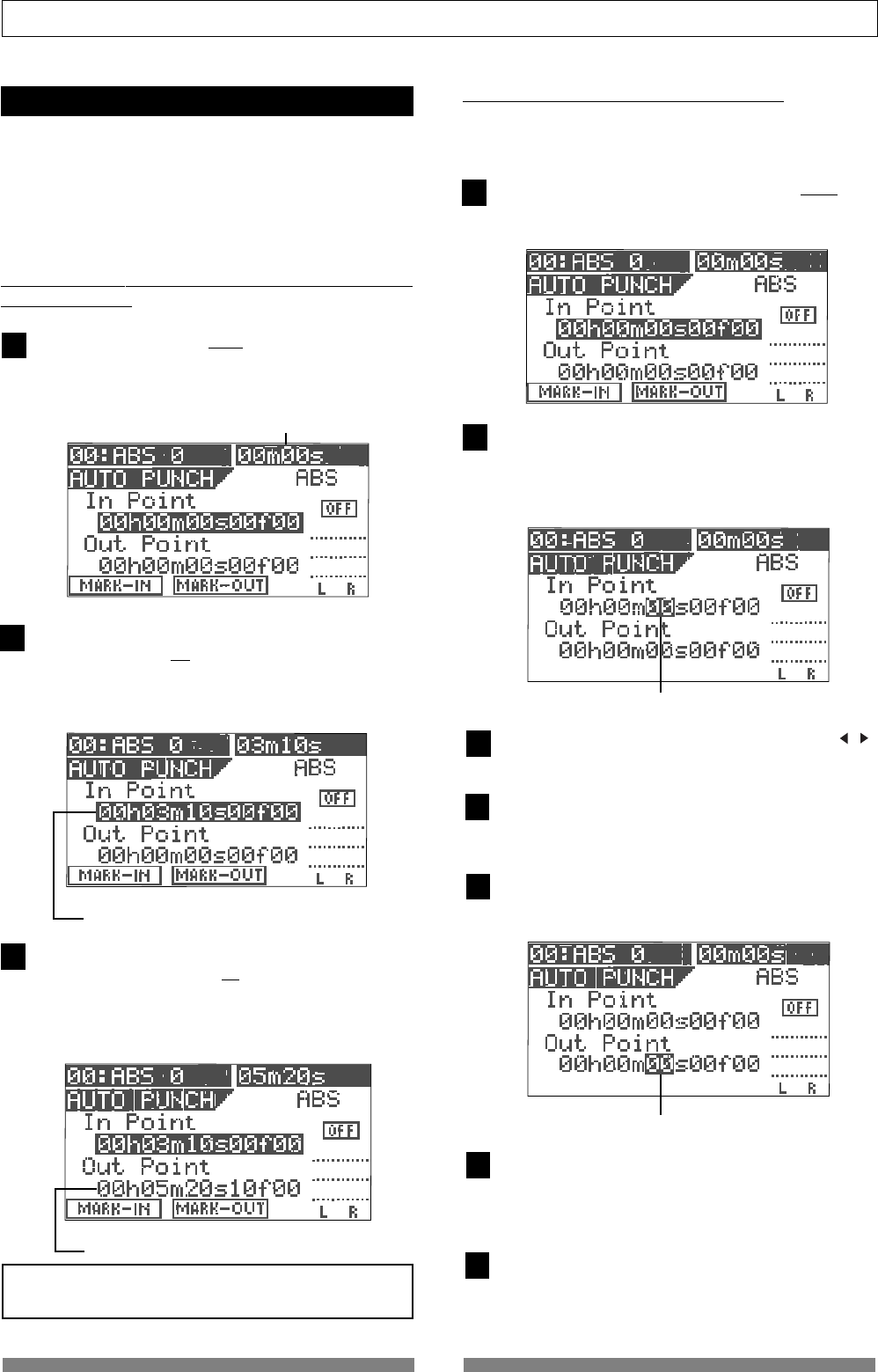
34
Basic Recording/Playback
3
1
During playback, this counter shows the current
recorder position in real time.
2
The time (or bar/beat) stored is shown here.
1
2
3
4
5
6
7
The time (or bar/beat) stored is shown here.
Flashing
Auto punch in/out function
You must set the punch in and out points before per-
forming auto punch in/out recording.
You can set the points either during playback and
while stopped. In the following description, we assume
that the “ABS” time base is selected.
• Setting the punch in/out points on the fly during playback
(or while stopped)
Press the [AUTO PUNCH/EDIT] key while holding down
the [SHIFT] key.
The screen for setting the punch in/out points appears.
At the point at which you want to set the punch in point,
press the [SETUP/F1] key while holding down the
[SHIFT] key.
“In Point Stored!” appears briefly, and the point is stored
as the punch in point.
At the point at which you want to set the punch out point,
press the [TIME BASE SEL/F2] key while holding down
the [SHIFT] key.
“Out Point Stored!” appears briefly, and the point at which
you carry out the operation above is stored as the punch
out point.
<Note>
Set the punch in point earlier than the punch out point.
• Setting the punch in/out points numerically
While the recorder is stopped, you can set the in and
out points by entering the time numerically.
While stopped, press the [AUTO PUNCH/EDIT] key
while holding down the [SHIFT] key.
The screen for setting the punch in/out points appears.
Press the [ENTER/YES] key while the punch in point
value is highlighted on the screen as above.
Now you can edit the punch in point value.
Initially, the “seconds” value starts blinking, showing
that it can be edited.
Move the blinking value by using the [CURSOR / ]
key and enter the desired value using the [JOG] dial.
After completing editing the time value, press the [EN-
TER/YES] key.
The edited time is stored as the punch in point.
Use the [CURSOR down] key to highlight the punch out
point value, and press the [ENTER/YES] key.
Now you can edit the punch out point value.
Flashing
Enter the desired value with the same method as en-
tering the punch in point, then press the [ENTER/YES]
key.
The edited time is stored as the punch out point.
After storing times for both points, press the [EXIT/NO]
key.
The LCD returns to the Normal screen.
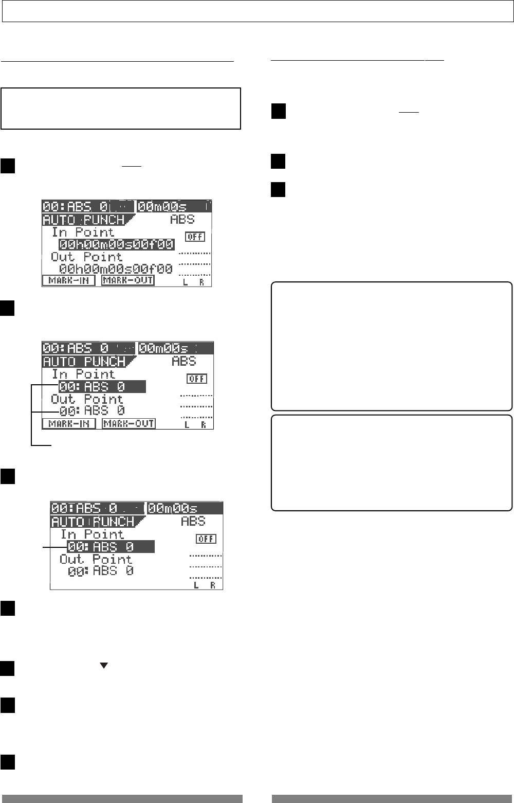
35
Basic Recording/Playback
1
2
3
Showing a mark.
1
2
3
4
Blinking
5
6
• Taking a mark point in the punch in or punch out point
You can take a mark point in the punch in or out point.
<Note>
The following operation is possible only when any marks
are stored using the Mark function described earlier.
Press the [AUTO PUNCH/EDIT] key while holding down
the [SHIFT] key.
The screen for setting the punch in/out points appears.
Press the [TIME BASE SEL] key when the in point time
value is highlighted (as above).
The highlighted line changes to show a mark.
Press the [ENTER/YES] key.
The highlighted mark starts blinking.
Use the [JOG] dial to select the desired mark, and then
press the [ENTER/YES] key.
The selected mark position is taken in the punch
in point.
Use the [CURSOR ] key to highlight the punch out
point value, and press the [ENTER/YES] key.
Use the [JOG] dial to select the desired mark, and then
press the [ENTER/YES] key.
The selected mark position is taken in the punch out
point.
After setting both points, press the [EXIT/NO] key.
7
• Performing auto punch in/out recording
After storing the punch in and out points, you can
perform the auto punch in/out recording.
Press the [AUTO PUNCH /EDIT] key (to illuminate the
key).
The auto punch mode is now active.
Locate the earlier position to the punch in point.
Press the [RECORD] key while holding down the
[PLAY] key.
A “take” of auto punch in/out recording starts and
“TAKE” lights up on the screen.
The recorder starts playback, and then automatically
puts into the record mode at the punch in point. It
automatically switches to playback at the punch out
point.
<Rehearsal>
In the step 3) above, if you press only the [PLAY] key,
a “rehearsal” of auto punch in/out recording starts
and “RHSL” lights up on the screen.
In the rehearsal mode, when the recorder reaches
the punch in point, only the monitor of the armed
track(s) switches to “Input monitor” without perform-
ing actual recording.
You can rehearse as many times as you like before
actual recording.
Hint:
If you use the loop function together with the re-
hearsal mode, you can rehearse your playing re-
peatedly without the need of the recorder opera-
tion, allowing you to concentrate on your playing.
See “Recorder functions” for details about the loop
function.
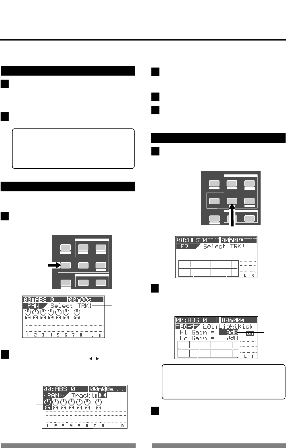
36
Basic Recording/Playback
1
1
2
MASTERING TRAINING
EFFECTEQPAN
SCENE SEQ.SCENE
TRACK
MIX PARAMETER
PGM FADER MAP
ON/OFF
2TRK MODE
BOUNCE
EDIT
REC EFF
[PAN] key
2
3
4
5
1
MASTERING TRAINING
EFFECTEQPA N
SCENE SEQ.SCENE
TRACK
MIX PARAMETER
PGM FADER MAP
ON/OFF
2TRK MODE
BOUNCE
EDIT
REC EFF
[EQ] key
2
3
Flashing
Mixing
After recording all tracks (1 through 8), you can tailor the sound of each track. The following describes about
settings for level, pan, EQ and effects.
Adjusting levels
Adjust the playback level of each track using the cor-
responding fader (1 through 6 and 7/8).
The levels of tracks 7 and 8 are simultaneously con-
trolled by a single fader (7/8).
Adjust the stereo master output (ST OUT L/R) levels
using the [MASTER] fader.
<About master output levels>
You can view the stereo master output (L/R) levels
from the L/R level meters on the screen. The output
levels are affected by the [MASTER] fader position.
Be sure not to set the fader level too high to avoid
the sound distorted.
Setting pan position
You can set the pan position of each track.
Press the [PAN] key.
The pan setting screen is shown, where “Select TRK!” is
flashing in the initial condition.
Press the [TRACK STATUS/TRACK SEL] key of the de-
sired track (or use the [CURSOR / ] keys to select
the desired track).
The pan icon of the selected track is highlighted, show-
ing that it is editable.
highlighted
Flashing
highlighted
Set the pan position using the [JOG] dial.
The pan icon on the screen changes in real time accord-
ing to the rotation of the [JOG] dial.
Repeat steps 2) and 3) to set other tracks.
After completing the pan setting, press the [EXIT/NO]
key.
The LCD returns to the Normal screen.
Adjusting EQ
Press the [EQ] key.
The EQ screen is shown, where “Select TRK!” is flashing
in the initial condition.
Press the [TRACK STATUS/TRACK SEL] key of the de-
sired track.
The default preset library entry (“L00: 2-SHLV”) is
shown, in which the High Gain field is highlighted,
showing that it can be edited.
<Selecting from the EQ library>:
There are 36 presets besides the default preset in the
EQ library. You can select a desired preset accord-
ing to the situation and tailor the sound. See “Mixer
functions” for details.
Edit the “Hi Gain” value using the [JOG] dial.
The EQ curve is shown according to the value setting,
while the sound changes in real time.
You can set the value between -18 dB and + 18 dB.
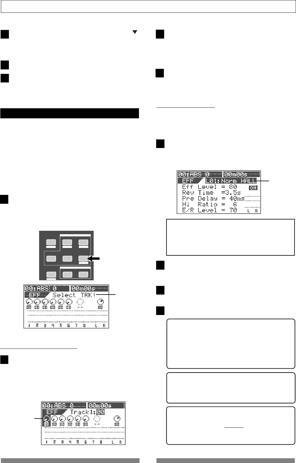
37
Basic Recording/Playback
3
4
2
3
4
1
MASTERING TRAINING
EFFECTEQPAN
SCENE SEQ.SCENE
TRACK MIX PARAMETER
PGM FADER MAP
ON/OFF
2TRK MODE
BOUNCE
EDIT
REC EFF
[EFFECT] key
2
5
6
4
Flashing
Highlight the “Lo Gain” field by using the [CURSOR ]
key, and edit the “Lo Gain” value using the [JOG] dial.
You can set the value between -18 dB and + 18 dB, as
same as the Hi Gain.
Repeat steps 2 through 4 to edit EQ on other tracks.
After completing the EQ setting, press the [EXIT/NO]
key.
The LCD returns to the Normal screen.
Setting effects
Press the [EFFECT] key.
The effect send level setting screen appears initially.
Each press of the [EFFECT] key switches between the
effect send level setting screen, effect type selection
screen and effect send pre/post selection screen.
Effect send level setting
While the effect send level setting screen is shown,
press the [TRACK STATUS/TRACK SEL] key of the
desired track.
The effect knob icon of the selected track is highlighted,
showing that it can be edited. The default value for track
sends 1 through 6 is “0” while the default value for the
master is “80”.
Use the [JOG] dial to enter the send level.
While the send level changes, the corresponding icon
also changes in real time.
When the value increases, the effect sound of the cur-
rently selected effect type will be output.
To set the effect send levels for other tracks, carry out
step 2 and 3 above repeatedly.
Effect type setting
The VF80 provides 38 effect types (L01 through L38) used
for the loop effect and 6 effect types (L39 through L44) used
for the insert effect.
Bring up the effect type setting screen and select the
desired effect type by rotating the [JOG] dial.
While rotating the [JOG] dial, the effect type appears
one after the other among 38 types (L01 ~ L38).
After selecting the desired effect type, press the [EN-
TER/YES] key.
The selected effect type is set.
Press the [EFFECT] key to bring up the effect send level
setting screen.
Adjust the effect send levels as described above.
<Pre/post setting of effect sends>
All the effect sends from tracks 1 through 6 are
initially set to “post-fader”. Therefore, when a track
fader is completely down, no signal is sent even if
you raise the effect send level of the track.
You can also select “pre-fader” if necessary.
See “Mixer functions” for details.
<Parameter setting for each effect type>
You can set parameters for the selected effect type.
See “Mixer functions” for details about parameter
setting.
<On/Off setting of the effect>
You can switch on or off the effect alternately by
pressing the [EFFECT/ON/OFF] key while holding
down the [SHIFT] key.
See “Mixer functions” for details.
5
highlighted
There are two methods for using the internal effect
processor of the VF80: “loop effect” and “insert effect”.
The following describes how to set the send level and
select an effect type of the loop effect.
See “Mixer Function” for details about the loop effect,
such as how to make pre/post setting of an effect send
or how to set effect parameters.
See also “Advanced Operations” on page 83 for details
about the insert effect. Highlighted
<Note>
If you select an effect type used for the insert effect
(i.e. any one of L39 through L44), the screens for
effect type selection and effect send pre/post selec-
tion are not shown.
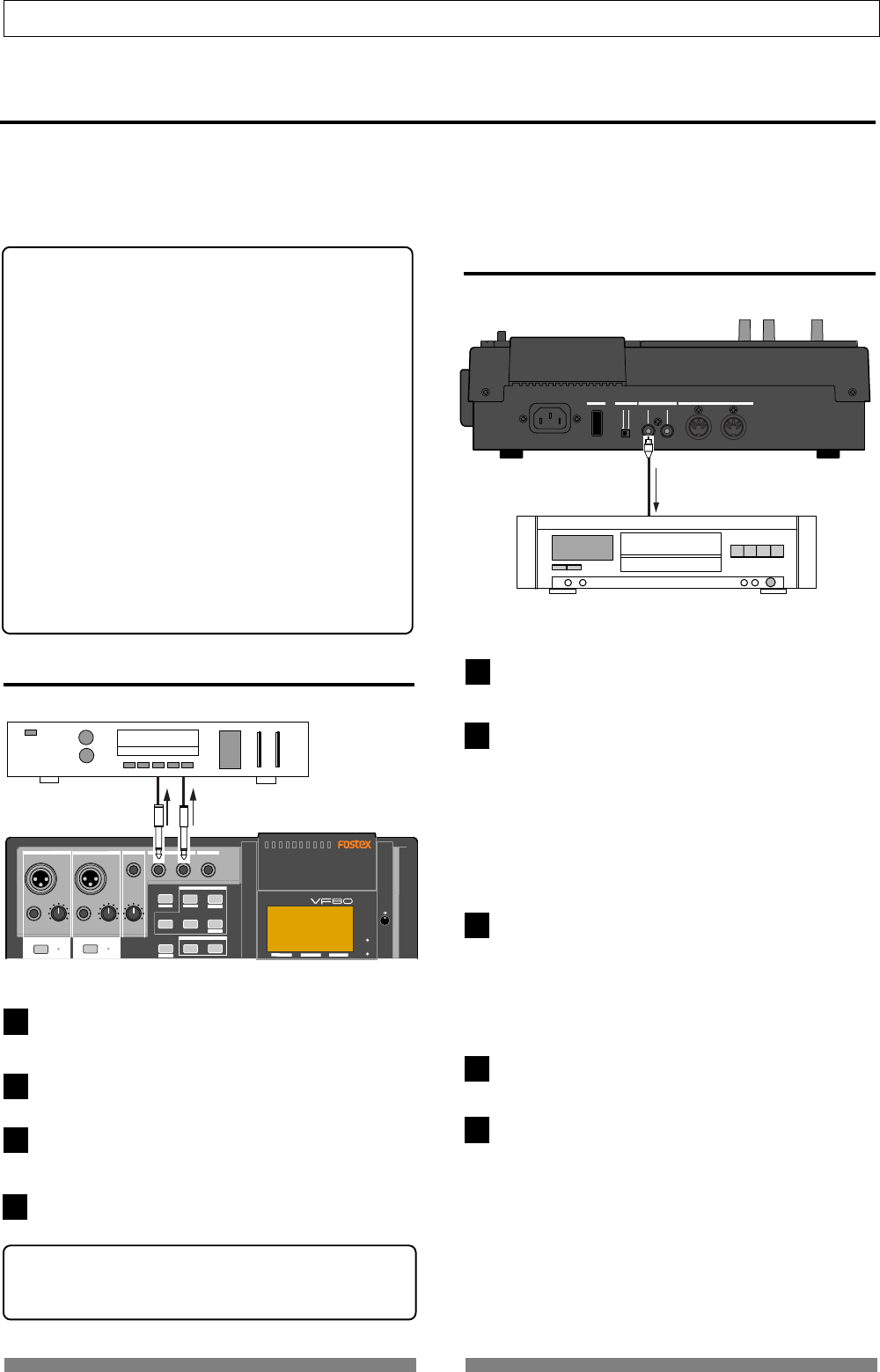
38
Basic Recording/Playback
DIGITAL MULTITRACKER
PHANTOM
ACCESS
PEAK
CH ON/OFF
LR
GUITAR
GUITAR
LINE MIC LINE MIC MIN MAX
MASTERING TRAINING
EFFECTEQPAN
SCENE SEQ.SCENE
TRACK
TRIMTRIM
MIX PARAMETER
PGM FADER MAP
ON/OFF
2TRK MODE
FOOT SW
ST OUT
PHONES
INPUT A
BOUNCE
INPUT B
PEAK
CH ON/OFF
UNBAL UNBAL
BAL
BAL
F1 F2 F3
EDIT
REC EFF
OFF
ON
MIDI
OUTPUT INPUT OUTPUT
INPUT
POWER PHANTOM S/P DIF / DATA
1
2
3
4
Analog master recorder
Digital master recorder
1
2
3
4
5
Mixdown
After tailoring sound of all the tracks, let’s make a master tape (disc) using your master recorder (cassette, DAT,
MD, etc.). As the VF80 can feed the stereo outputs (L and R) via the S/PDIF (coaxial) digital output jack, you can
make the master tape (disc) in digital domain if your recorder provides a digital input jack. If your digital re-
corder only provides the optical input jack, use the Fostex COP-1 optical to coaxial converter.
<Using the mastering mode/internal mastering mode:>
The VF80 provides the “mastering mode” and “internal
mastering mode”.
In the mastering mode, you can record a material mixed
down to track 7 and 8 to an external master recorder,
while applying sound processing. The mastering mode
allows you to perform advanced mastering.
See “Advanced Operations” on page 76 for details about the
mastering mode.
In the internal mastering mode, you can create a master song
inside the VF80, without the need of using an external
master recorder. Also, you can create an audio CD from
master materials mastered in the mastering mode. (Note
that you need the optional CD-RW drive to create an audio
CD.)
See “Advanced Operations” on page 79 for details about the
internal mastering mode, and “Save/load of song data” on
page 115 for details about creating an audio CD.
Analog mixdown
Connect the [ST OUT - L/R] jacks to the input jacks of
your analog master recorder.
Set the recording level of the master recorder.
Start recording the master recorder, and start playback
of the VF80 from the beginning of the song.
When recording finishes, stop both the units.
<Fade in/out:>
You can fade in or fade out a song by using the [MASTER]
fader.
Connect the [DATA OUTPUT] jack to the digital input
jack of your master recorder.
Set the master recorder’s recording source to the digi-
tal input.
• The sampling frequency of the VF80 is fixed to 44.1
kHz, so you cannot record the VF80 digital output
signal to the master recorder that cannot accept 44.1
kHz digital signals.
• In general, you cannot adjust the digital input level
of a digital recorder.
Adjust the stereo output level of the VF80 using the
[MASTER] fader.
• In general, set the fader so that the level meter on the
master recorder indicates “0” when the VF80 feeds
the loudest level signal.
If the level is too high, the sound may be distorted.
Start recording the master recorder, and start playback
of the VF80 from the beginning of the song.
When recording finishes, stop both the units.
Digital mixdown
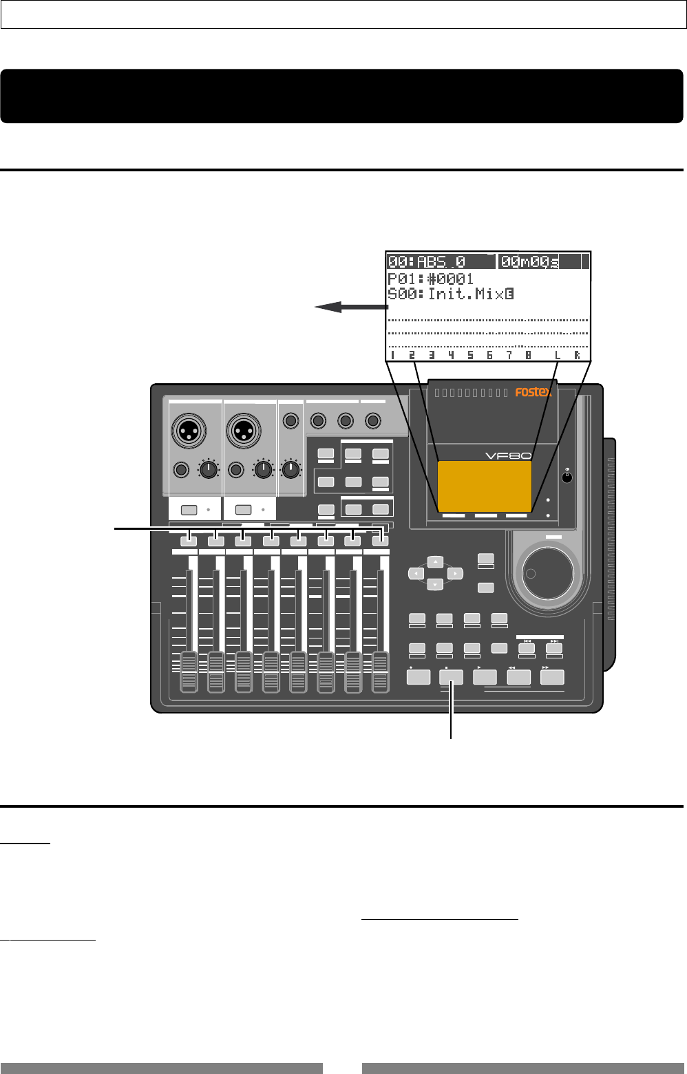
39
Mixer Functions
Normal screen
DIGITAL MULTITRACKER
LOCATE ABS 0
LOCATE REC END
SEL
TIMEBASE
CURSOR
PHANTOM
ACCESS
PEAK
CH ON/OFF
LR
GUITAR
GUITAR
LINE MIC LINE MIC MIN MAX
MASTERING TRAINING
EFFECTEQPAN
SCENE SEQ.SCENE
TRACK
UNDO
SETUP
PUNCH
AUTO LOOP PITCH SCRUB
VARI
F FWDREWINDPLAYSTOPRECORD
EXIT
ENTER
TRIMTRIM
WAVE FORM
MIX PARAMETER
PGM FADER MAP
ON/OFF
2TRK MODE
F1 F2 F3 SHIFT
EDIT EDIT EDIT MARK DELETE
LOCATE
FOOT SW
ST OUT
PHONES
INPUT A
BOUNCE
INPUT B
+6
-10
-20
-40
-
∞
-30
0
+6
-10
-20
-40
-
∞
-30
0
+6
-10
-20
-40
-
∞
-30
0
+6
-10
-20
-40
-
∞
-30
0
+6
-10
-20
-40
-
∞
-30
0
+6
-10
-20
-40
-
∞
-30
0
+6
-10
-20
-40
-
∞
-30
0
+6
-10
-20
-40
-
∞
-30
0
PEAK
CH ON/OFF
2345 6 7/8 2TRK1 MASTER
TRACK STATUS / TRACK SEL
TRACK STATUS RED REC GREEN PLAY OFF MUTE STATUS
/SEL
EJECT
/YES
/NO
SHUTTLE
JOG
UNBAL UNBAL
BAL
BAL
F1 F2 F3
EDIT
/REDO
REC EFF
Lighting in green
Lighting in orange
Mixer Functions
Initial condition when turning on the power
When turning on the power, the VF80 starts up while showing the unit information on the LCD display and then
gets ready when the screen below appears. This screen is called "Normal Screen", in which the program number
and current recorder position are shown. In the following example (the default), Program 1 (P01) is loaded and
the current position is the beginning (ABS 00M 00S).
Operations while the Normal screen is shown
Fader
The fader for each track (1 through 6 and 7/8) con-
trols the level of the playback signal fed to the stereo
outputs.
Track mute
While the VF80 is not in the mix parameter edit mode,
pressing any one of the [TRACK STATUS/TRACK SEL]
keys (for tracks 1 through 6 and 7/8) mutes the cor-
responding track.
The [TRACK STATUS/TRACK SEL] key for the muted
track is unlit. Pressing the key again releases muting
and lights up the key.
Master fader mute
While the VF80 is not in the mix parameter edit mode,
pressing the [STATUS/SEL] key for the master fader
mutes the stereo outputs.
While the stereo outputs are muted, the [STATUS/SEL]
key is unlit. Pressing the key again releases muting
and lights up the key.
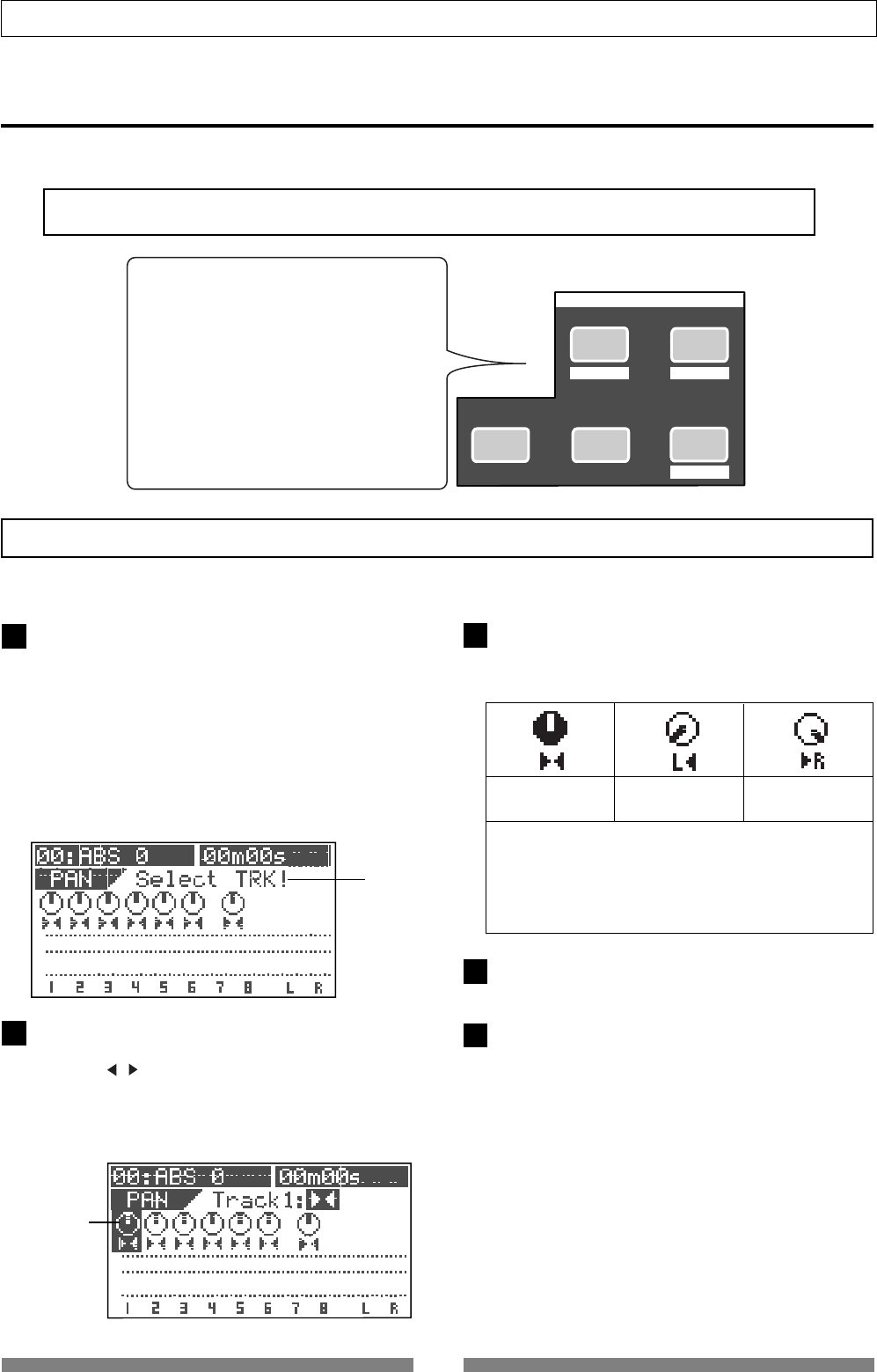
40
Mixer Functions
Flashing
EFFECTEQPAN
SCENE SEQ.SCENE
MIX PARAMETER
FADER MAP
ON/OFF
1
2
4
3
5
Mix parameter section
The Mix parameter section provides five keys that are used for mixer function settings.
By pressing one of these keys alone or while holding down the [SHIFT] key, you can execute the following.
•Pan setting
•EQ setting
•Effect send level setting
•Effect send pre/post setting
•Effect type/parameter setting
•Effect on/off setting
•Save/load/delete of a scene memory
•Scene sequence mode on/off setting
•Mark map setting
•Fader view
Adjusting pan positions
You can adjust the pan position of each track signal fed to the stereo outputs.
Press the [PAN] key.
The pan screen appears.
If you have not edited any track parameter for pan, EQ
or effect send setting after turning on the power last
time, the message prompting to select a track ("Select
TRK!") flashes, as well as all the [TRACK STATUS/TRACK
SEL] keys on the panel flash.
If you have edited any track parameter for pan, EQ or
effect send setting after turning on the power last time,
the icon for the previously edited track is highlighted,
showing that it can be edited.
Select the desired track by pressing the correspond-
ing [TRACK STATUS/TRACK SEL] key (or using the
[CURSOR / ] keys).
The pan icon of the selected track is highlighted, indi-
cating that you can edit it.
The [TRACK STATUS/TRACK SEL] key of the selected track
flashes.
Highlighted
Use the [JOG] dial to adjust the pan position.
The pan position is set according to the rotating degree.
The following show examples of the pan settings.
•Controllable tracks
Tracks 1 through 6 and 7/8
•Available values
L10 (hard left) through C (center) to R10 (hard right)
(the default setting: "C" for all tracks)
Pan position:
center Pan position:
hard left
Pan position:
hard right
To adjust the pan position for another track, repeat
steps 2 and 3 above.
After completing pan setting, press the [EXIT/NO] key.
The VF80 exits the mix parameter edit mode and the
LCD display returns to the Normal screen.
<Note>
The VF80 mixer channels always receive corresponding track signals. They do not receive input signals.
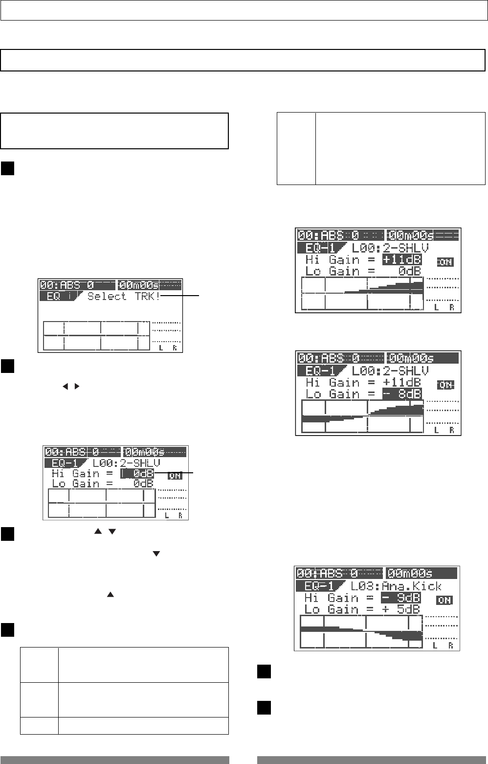
41
Mixer Functions
Flashing
1
2
3
4
5
6
Editing EQ
The VF80 is equipped with 2-band (HI and LO) EQ for Tracks 1 through 6.
36 preset entries are available in the EQ library.
<Note>
You can apply EQ only to Tracks 1 through 6. You cannot
apply EQ to Tracks 7/8.
Press the [EQ] key.
The EQ screen appears.
If you have not edited any track parameter for EQ, pan
or effect send setting after turning on the power last
time, the message prompting to select a track ("Select
TRK!") flashes, as well as the [TRACK STATUS/TRACK
SEL] keys for Tracks 1 through 6 on the panel flash.
If you have edited any track parameter for pan, EQ or
effect send setting after turning on the power last time,
the icon for the previously edited track is highlighted,
showing that it can be edited.
Select the desired track by pressing the correspond-
ing [TRACK STATUS/TRACK SEL] key (or using the
[CURSOR / ] keys).
The selected track number and library entry name
(shown as "EQ-1" and "L00: 2-SHLV" respectively in the
screen example below) are shown, together with the
current settings. The gain value of Hi EQ ("Hi Gain")
flashes, indicating that you can edit it.
Use the [CURSOR / ] key to select a parameter to
be edited.
Each time you press the [CURSOR ] key, the flashing
parameter (to be edited) changes in the following or-
der. Hi Gain -> Lo Gain -> EQ ON/OFF -> library entry
->Hi Gain...
Pressing the [CURSOR ] key changes the flashing pa-
rameter in the reverse order.
Use the [JOG] dial to edit the parameter value.
The following values are available for each parameter.
Hi Gain
Lo Gain
ON/OFF
-18 dB through 0 dB to +18 dB in 1 dB steps.
The current EQ curve is shown graphically accord-
ing to the current values.
-18 dB through 0 dB to +18 dB in 1 dB steps.
The current EQ curve is shown graphically accord-
ing to the current values.
ON or OFF of EQ
Library
Selectable from 36 preset library entries (L00
through L36). The default is "L00: 2-SHLV.
After selecting the desired library, press the [EN-
TER/YES] key to confirm the setting.
*See the following table for details about the EQ
library.
Setting example 1: Set "Hi Gain" to "+11 dB."
The high frequency gain is boosted up as shown graphi-
cally.
Setting example 2: Set "Lo Gain" to "-8 dB."
The low frequency gain is cut as shown graphically.
Setting example 3: Set "EQ library" to "L03."
The high frequency gain is boosted up as shown graphi-
cally.
By using the [JOG] dial to select "L03": Ana.Kick" and
pressing the [ENTER/YES] key, the preset parameter
values are shown together with the corresponding EQ
curve.
You can edit parameters from this preset condition and
store the setting as a scene. Note that if you turn off
the power, the setting is cleared.
To edit the EQ for another track, repeat steps 2 through
4.
After completing EQ editing, press the [EXIT/NO] key.
The VF80 exits the EQ edit mode and the LCD display
returns to the Normal screen.
Flashing
42
Mixer Functions
Gain
Freq.
Q
LO HI
+6.0 -12.0
400Hz 600Hz
L-S 5.0
L01: LightKick
Creates a light and jaunty kick
sound
Gain
Freq.
Q
LO HI
+7.0 +10.0
400Hz 4kHz
L-S 8.0
L02: TightKick
Gain
Freq.
Q
LO HI
+5.0 -9.0
550Hz 6kHz
L-S H-S
L03: Ana.Kick
Gain
Freq.
Q
LO HI
-7.0 +6.0
1kHz 3.5kHz
L-S 2.5
L04: Snappy_SD
Gain
Freq.
Q
LO HI
+8.0 +5.0
150Hz 3.5kHz
4.5 2.5
L05: Power_SD
Gain
Freq.
Q
LO HI
+3.0 +4.0
550Hz 4.3kHz
4.5 2.2
L06: Deep_SD
Gain
Freq.
Q
LO HI
+4.0 +7.0
100Hz 3.2kHz
7.1 6.3
L07: Talk_Tom
Gain
Freq.
Q
LO HI
+6.0 -12.0
100Hz 1.7kHz
2.8 2.2
L08: Melo.Tom
Creates a tight and hard kick sound.
Makes an analog kick sound boomy.
Makes a snare sound snappier.
Creates a powerful and heavy snare
sound.
Creates a heavy sound of a snare
drum with a deep body.
Creates a skinny tom-tom sound.
Creates a melodious sound.
Flat setting
The first time you bring up the EQ
screen, this entry is selected.
Gain
Freq.
Q
LO HI
00
400Hz 4kHz
L-S H-S
L00: 2-SHLV
Removes the brightness from a
cymbal sound by cutting high fre-
quencies.
Gain
Freq.
Q
LO HI
+3.0 -18.0
300Hz 8kHz
1.6 H-S
L10: Lo-Fi_Cym
Gain
Freq.
Q
LO HI
-4.0 +7.0
100Hz 6kHz
L-S H-S
L11: Perc.
Gain
Freq.
Q
LO HI
-8.0 +10.0
360Hz 5.4kHz
L-S H-S
L12: Tamb.
Gain
Freq.
Q
LO HI
+5.0 +3.0
100Hz 2.4kHz
0.1 6.3
L13: Fat_Bass
Gain
Freq.
Q
LO HI
+5.0 +4.0
190Hz 2.4kHz
1.0 1.0
L14: Norm.Bass
Gain
Freq.
Q
LO HI
+4.0 +3.0
120Hz 1.3kHz
2.0 2.2
L15: Loud_Bass
Gain
Freq.
Q
LO HI
-3.0 +4.0
340Hz 5kHz
0.9 H-S
L16: Bright_Pf
Gain
Freq.
Q
LO HI
+5.0 -3.0
200Hz 1.3kHz
L-S 0.9
L17: Loud_Pf
Gain
Freq.
Q
LO HI
-13.0 +7.0
170Hz 5.4kHz
0.7 1.1
L18: Power_Pf
Gain
Freq.
Q
LO HI
+8.0 +3.0
1kHz 6.4kHz
0.7 1.7
L19: E.Pf
Creates a bright sound by empha-
sizing the attack of a conga, bongo,
etc.
Creates a subtle sound by empha-
sizing the presence of a tambourine,
etc.
Creates a fat base sound by slightly
boosting the low frequency range.
Creates a all-round bass sound.
Creates a good analog bass sound
by boosting the low frequency range
and emphasizing the attack.
Creates a bright piano sound.
Creates a rich piano sound by
boosting the low frequency range
which contains rich harmonics.
Creates a tight and smooth sound.
Suitable for a piano solo.
Creates a sound which emphasizes
the attack and distortion when hit-
ting keyboards of an electric piano.
Gain
Freq.
Q
LO HI
-10.0 +17.0
130Hz 520Hz
L-S 7.1
L09: W.GongTom
Makes a tom-tom sound woody.
Preset entries in the EQ library
43
Mixer Functions
Gain
Freq.
Q
LO HI
-5.0 +4.0
170Hz 5.8kHz
0.7 H-S
L31: Female_Vo
Effective for a whole chorus part by
emphasizing the high frequency
range.
Gain
Freq.
Q
LO HI
-5.0 +5.0
120Hz 10kHz
0.7 H-S
L32: Chorus
Gain
Freq.
Q
LO HI
ON +3.0
180Hz 10kHz
HPF H-S
L33: SpeeCh
Gain
Freq.
Q
LO HI
+5.0 +6.0
100Hz 12kHz
L-S H-S
L34: Digi.Mix
Gain
Freq.
Q
LO HI
ON ON
250Hz 8kHz
HPF LPF
L35: AnalogMix
Gain
Freq.
Q
LO HI
ON ON
1.2kHz 5.6kHz
HPF LPF
L36: Telephone
Effective for a female vocal
Makes a narration clear.
Makes an analog open-reel or cas-
sette tape sound closer to a digital
sound.
Cuts the high frequency range and
provides an opposite character to
L34.
Emphasizes the mid range only to
provide a telephone receiver sound.
Gain
Freq.
Q
LO HI
-4.0 +4.0
100Hz 6.6kHz
L-S H-S
L20: Clean_EG
Makes a moderately distorted
crunch electric guitar sound distinc-
tive.
Gain
Freq.
Q
LO HI
-2.0 +6.0
120Hz 4kHz
0.7 1.4
L21: CrunCh_EG
Gain
Freq.
Q
LO HI
+6.0 +7.0
310Hz 1.3kHz
1.5 1.1
L22: OverDrvEG
Gain
Freq.
Q
LO HI
+6.0 +4.0
370Hz 3.6kHz
L-S 10
L23: Dist.EG
Gain
Freq.
Q
LO HI
+3.0 +12.0
230Hz 14kHz
0.7 H-S
L24: Metal_EG
Gain
Freq.
Q
LO HI
-9.0 +8.0
100Hz 9kHz
0.7 1.2
L25: Stroke_AG
Gain
Freq.
Q
LO HI
-2.0 +3.0
210Hz 9.4kHz
L-S 0.1
L26: Arpeg.EAG
Gain
Freq.
Q
LO HI
-7.0 +5.0
530Hz 4.4kHz
7.1 H-S
L27: Arpeg.AG
Gain
Freq.
Q
LO HI
+3.0 +4.0
125Hz 260Hz
L-S 2.2
L29: W.WindSec
Gain
Freq.
Q
LO HI
+2.0 +3.0
2kHz 6.2kHz
0.5 H-S
L30: Male_Vo
Adds a bright character to a trans-
parent and clean electric guitar
sound.
Makes a mellow overdriven electric
guitar sound fatter.
Makes a hardly distorted electric
guitar sound distinctive.
Makes a high-gain metal sound dis-
tinctive.
Suppresses a hole resonance of an
acoustic guitar and makes a code
stroke sound powerful.
Controls the arpeggio code balance
of an electro-acoustic guitar.
Suppresses a hole resonance of an
acoustic guitar and makes an ar-
peggio brighter.
Controls the balance of brass instru-
ments (such as trumpets, trom-
bones. etc.).
Makes the mid frequency range of
woodwind instruments (such as
clarinets, oboe, etc.) richer.
Effective for a male vocal
Gain
Freq.
Q
LO HI
-3.0 +4.0
100Hz 5.6kHz
2.5 5.0
L28: Brass_Sec
Tips:
“L-S” (Low shelving type)
This equalizer affects all frequencies below a specified
frequency when applying boost or cut.
“H-S” (High shelving type)
This equalizer affects all frequencies below a specified
frequency when applying boost or cut.
“LPF” (Low pass filter)
This filter passes frequencies below a cut-off frequency
while cuts frequencies above the frequency.
“HPF” (High pass filter)
This filter passes frequencies below a cut-off frequency
while cuts frequencies above the frequency.
44
Mixer Functions
Setting Effects
The VF80 provides 38 digital effect types used for the loop effect and 6 types used for the insert effect.
As you can select any type and adjust parameter settings for each type, comprehensive effect pro-
cessing is possible.
Employing the Fostex A.S.P. (Fostex Advanced Signal Processing Technology*), the internal DSP multi-
effect processor realizes superb ambience effects. In addition, the newly developed "A.S.P. +" achieves
simulations of microphones/amplifiers with overwhelming reality.
* A. S. P. (Fostex Advanced Signal Processing Technology)
The A. S. P. is an exclusive new digital effect processing technology designed by Fostex.
This method extracts maximum efficiency from the limited DSP power.
It achieves an overwhelmingly high density Early Reflection sound and wonderfully smooth
High Dump response through the H. F. A. (Harmonic Feedback Algorithm). Also, it car-
ries out an elaborate reverb simulation with clear sounds through the H. D. L. P. (Hi-
Density Logarithmic Processing), which eliminates the mutual interference between the
numerous integrated delay modules and reduce the impurity and girt of the sound.
* H. F. A. (Harmonic Feedback Algorithm)
There is one of indispensable elements in the natural echo called “Early Reflection Sound,” which is usually
sacrificed in commercial reverb products in order to reduce costs. (In practice, the Early Reflection Sound
means the very first reverberated sound that bounces back from walls, floors and ceilings of concert halls).
The entire reverb sound quality depends on this Early Reflection Sound and how closely it can resemble the
real echo. The H. F. A. is an algorithm that enables the effect unit to reproduce a clear and natural Early
Reflection Sound by applying an ideal harmonic feedback to each delay module.
* H. D. L. P. (Hi-Density Logarithmic Processing)
The reverb sounds consist of lots of small delay elements combined in a complex way, which are produced
by many delay modules inside the effect unit. In order to obtain smooth and comfortable reverb sounds,
it is very important to efficiently organize the relationship between each delay module and minimize
negative mutual interference. The H. D. L. P. is a technology which applies efficient logarithmic processing
to each delay module, so that they can work in the most efficient way in order to eliminate harmful reverb
elements and roughness. This makes it possible to establish high density and transparent sounds.
<About "Loop effect" and "Insert effect">
Using a loop effect you can process sound recorded on tracks during track bouncing (ping-pong) or mixdown.
The processed sound is recorded to the other track(s) of the unit or external master recorder.
Using an insert effect, you can process sound on any of tracks 1 through 6 using a distortion or simulation
effect, and rerecord the processed sound to the same track.
About "A.S.P.+"
Combining the ambience effect technology established through the development of "A.P.S."with acoustic
theories accumulated through the development of transducers such as monitor speakers for many years,
Fostex developed a unique simulation algorithm engine called "A.S.P.+", which performs overwhelmingly
realistic microphone/amplifier simulation.
To simulate a microphone, the frequency response of the microphone, which is the most essential factor
that decides the sound character of each famous/popular microphone, must be reproduced correctly. To
get this, "A.P.S.+" carries out a double accuracy operation for each frequency range using the unique "D.A.O."
(Double Accuracy Operation).
Regarding a guitar amplifier, the peak and dip of the specific frequencies, as well as feedback of the peak
frequency's harmonics, are the most essential factors that decide the sound character of each famous/popular
amplifier. To simulate such a unique character, "A.P.S.+" carries out a double accuracy operation for each
frequency range using the "D.A.O." (Double Accuracy Operation) to simulate the frequency curve, as well
as carries out harmonics feedback processing using the "H.F.A." (Harmonics Feedback Algorithm).
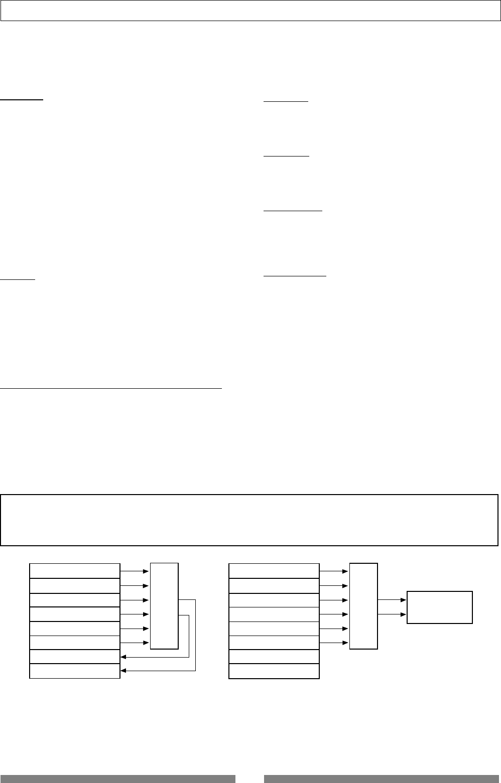
45
Mixer Functions
How to make the loop effect setting
There are two methods for using the internal effect processor of the VF80; "loop effect" and "insert
effect".
The loop effect allows you to apply a desired effect to track signals during track bounce (ping-pong)
operation to the other tracks or mixdown operation to an external master recorder.
The insert effect is applied when rerecording any of recorded tracks 1 through 6.
The following describes how to make settings for the loop effect. See "Advanced Operations" on page
83 for details about the insert effect.
Track 1
Track 2
Track 3
Track 4
Track 5
Track 6
Track 7
Track 8
ASP
Effect
Track 1
Track 2
Track 3
Track 4
Track 5
Track 6
Track 7
Track 8
ASP
Effect Master Recorder
Bouncing tracks 1 through 6 to tracks 7 and
8.
Mixing down tracks 1 through 6 and recording to an external
master recorder.
Before describing detail for the VF80 effect setting, we briefly explain each effect type (reverb, delay,
chorus, flanger, distortion and simulator).
Reverb:
The so called Reverb effect consists of various reflection
sounds mixed together. For example, when you clap your
hands in a tunnel, you will hear the sound linger even
after you stop clapping your hands. This is the Reverb.
The sounds we normally hear in daily life have three types
of sounds mixed together, i.e., “Direct sound,” “Early Re-
flection sound” and “Late Reflection sound.”
The Direct sound means the sound directly reaches the
ears from the sound source. The Early Reflection sound
means the sound that comes after the Direct sound and
has rebound off the wall of the tunnel up to a few times.
The Late Reflection sound means that the sound rebounds
many times long after the Direct sound has disappeared.
Our ears normally hear the “Direct sound” - “Early Reflec-
tion sound” - “Late Reflection sound” in the order.
Delay:
This is the effect to added a delayed sound to the original
sound. You can obtain a richer sound or completely change
the original source sound by using the Delay.
<Note>
The effect settings described here are only available to Tracks 1 through 6.
On Track 7/8, the dedicated "
Mastering processing"
is built in and you can apply the reverb, compressor, etc. while trans-
ferring audio on the master tracks (7/8) to an external recorder. See "
Advanced Operations
" for details.
Chorus:
This makes the one original sound appear to have many
sources. The Chorus is used to widen or thicken the origi-
nal sound.
Flanger:
The Flanger is one of applications of the Delay.
This is used to create a sound like a jet airplane ascending
or descending.
Distortion:
The distortion effect distorts the sound and adds harmon-
ics. Four types of the distortion effect are provided: the guitar
distortion, bass distortion, drum distortion and voice dis-
tortion. The distortion is used for the insert effect.
Simulation:
Simulators for famous guitar amplifiers and microphones
are provided. You can get a familiar distortion sound of a
famous guitar amplifier or a popular microphone sound. A
simulator can be used for the insert effect.
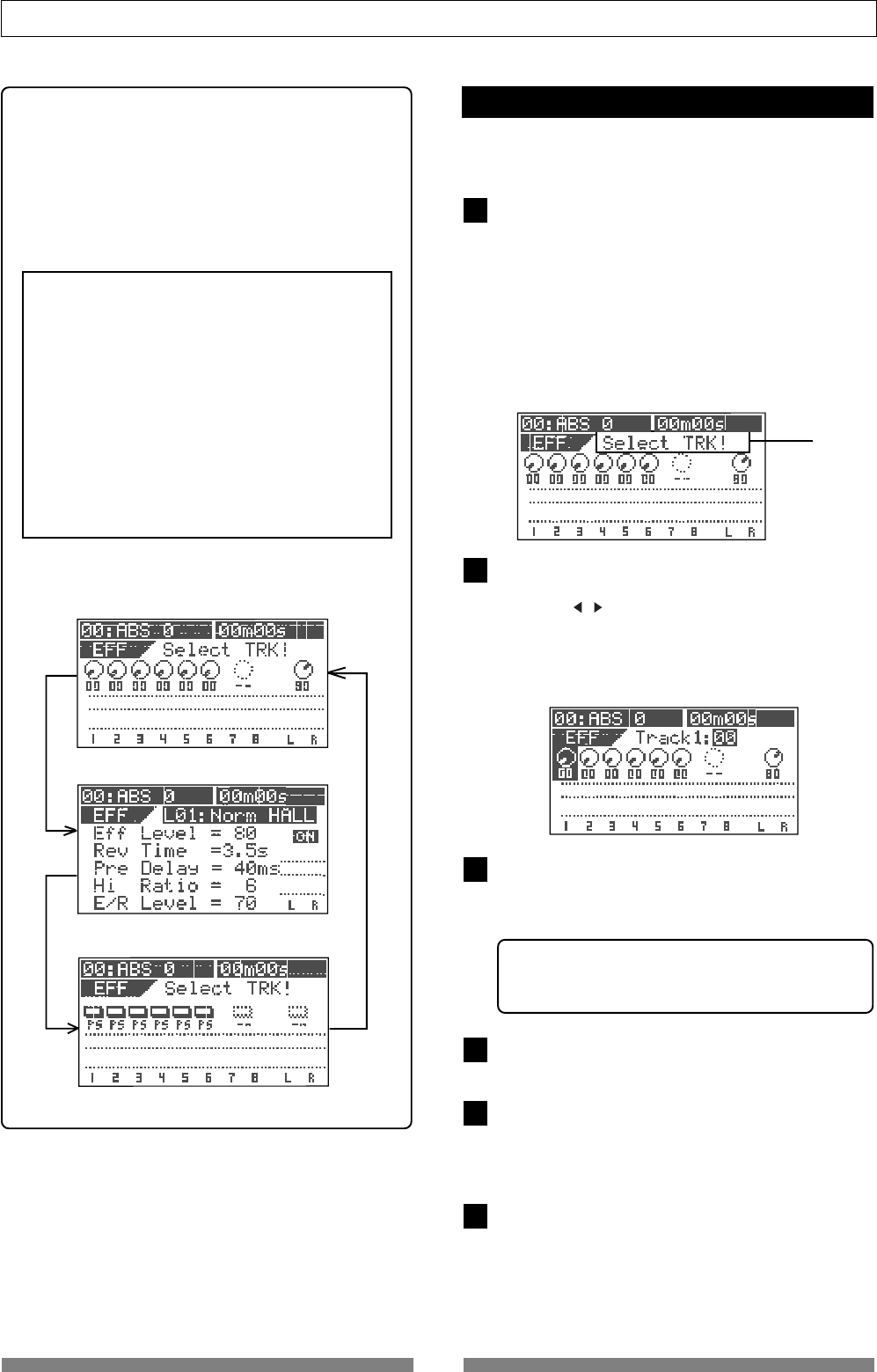
46
Mixer Functions
2
3
4
5
6
1
Flashing
Setting effect send levels
You can set send levels from Tracks 1 through 6 to the
internal A.S.P. effect processor.
Press the [EFFECT] key to bring up the send level
setting screen.
If you have not edited any track parameter for effect
send, EQ or pan setting after turning on the power last
time, the message prompting to select a track ("Select
TRK!") flashes, as well as the [TRACK STATUS/TRACK SEL]
keys for Tracks 1 through 6 on the panel flash.
If you have edited any track parameter for effect send,
EQ or pan setting after turning on the power last time,
the icon for the previously edited track is highlighted,
showing that it can be edited.
Select the desired track by pressing the correspond-
ing [TRACK STATUS/TRACK SEL] key (or using the
[CURSOR / ] keys).
The icon of the selected track is highlighted, indicat-
ing that you can edit it.
In the default settings, the send levels for Tracks 1
through 6 are "00" while the level for Master is "80."
Use the [JOG] dial to adjust the send level value.
The knob icon also rotates according to the level value.
When the level is set to "00", no signal is sent to the effect
processor.
• Editable tracks: Tracks 1 through 6
• Level range: 00 through 99 in 1 step
• Default level: Tracks 1 through 6: 00, Master: 80
To edit the send level for another track, repeat steps 2
and 3 above.
To edit the effect send master level, press the [STA-
TUS/SEL] key of the master to highlight the master
level icon, and then use the [JOG] dial to edit the value.
The default level value is "80."
After completing send level settings, press the [EXIT/
NO] key.
The LCD display returns to the Normal screen.
Effect send level setting screen
Effect type/parameter setting screen
Effect send pre/post setting screen
<Hint>
When editing the loop effect setting, pressing the
[EFFECT] key after turning on the power cycles
the screen between "Effect send level setting
screen", "Effect type/parameter setting screen" and
"Effect send pre/post setting screen", as shown
right.
<Note>
If you select one of effect types L39 through
L44, the "Effect type/parameter setting
screen" is shown and pressing the
[EFFECT]
key does not change the screen.
This is because effect types L39 through L44
are only used as insert effects and do not have
the "Effect send level setting screen" and
"Effect send pre/post setting screen"
See "Advanced Operations" on page 83 for
details about the insert effect.
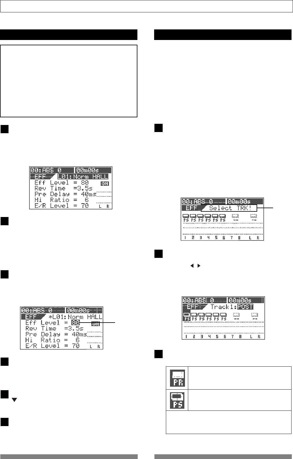
47
Mixer Functions
1
2
Selecting an effect type
Press the [EFFECT] key to bring up the effect type/
parameter setting screen.
The first time you bring up the screen, "L01: Norm HALL"
is selected as the effect type.
From the second time on when bringing up the screen,
the previously selected effect type is selected.
Use the [JOG] dial to select the desired effect type.
For the loop effect, you can select among L01 through
L38.
Effect types L39 through L44 are used for the insert
effect (described later).
When you select a type other than the current type, the
type flashes.
3
4
5
6
Edit point
Press the [ENTER/YES] key after selecting the effect
type.
Now you can edit the first parameter.
In the example below, the "Eff Level" value is highlighted
showing that it can be edited.
Use the [JOG] dial to select a value for the highlighted
parameter.
See "Effect parameter details" about the available pa-
rameter values.
To set a value for another parameter, use the [CURSOR
] key to select a parameter to be edited, and then use
the [JOG] dial to select a value.
After completing the settings, press the [EXIT/NO] key.
The VF80 exits the edit mode and the LCD display re-
turns to the Normal screen.
<Note>
Changing the effect preset may mute the sound mo-
mentarily!
Effect presets of the internal effect processor shown
above are classified into three types; ambience/de-
lay type (No. 1 through 28), modulation/pitch type
(No. 29 through 36), pitch type (No. 37 and 38) and
distortion/simulation type (No. 39 through 44).
If you switch the effect preset between the three types
above, the audio is momentarily muted.
• Selectable tracks: Tracks 1 through 6
• Setting values: PRE or POST (the default is POST).
Pre fader signal is sent to the effect processor.
Post fader signal is sent to the effect processor.
1
2
3
Flashing
Selecting Pre/Post of the effect send
You can select the send signals from Tracks 1 through
6 pre- or post- fader.
When selecting Post, a signal after the track fader is
sent to the effect processor. So if you set the fader
completely down, no signal is sent to the effect pro-
cessor.
When selecting Pre, a signal before the track fader is
sent to the effect processor. So even if you set the fader
completely down, the signal is sent to the effect pro-
cessor.
Press the [EFFECT] key to bring up the pre/post set-
ting screen.
If you have not edited any track parameter for effect
send, EQ or pan setting after turning on the power last
time, the message prompting to select a track ("Select
TRK!") flashes,as well as the [TRACK STATUS/TRACK SEL]
keys for Tracks 1 through 6 on the panel flash.
If you have edited any track parameter for effect send,
EQ or pan setting after turning on the power last time,
the switch icon for the previously edited track is high-
lighted, showing that it can be edited.
Select the desired track by pressing the correspond-
ing [TRACK STATUS/TRACK SEL] key (or using the
[CURSOR / ] keys).
The switch icon of the selected track is highlighted,
indicating that you can edit it.
In the default settings, all Tracks 1 through 6 are set to
"Post."
Use the [JOG] dial to select "Pre" or "Post."
The icon changes according to the selection as below.
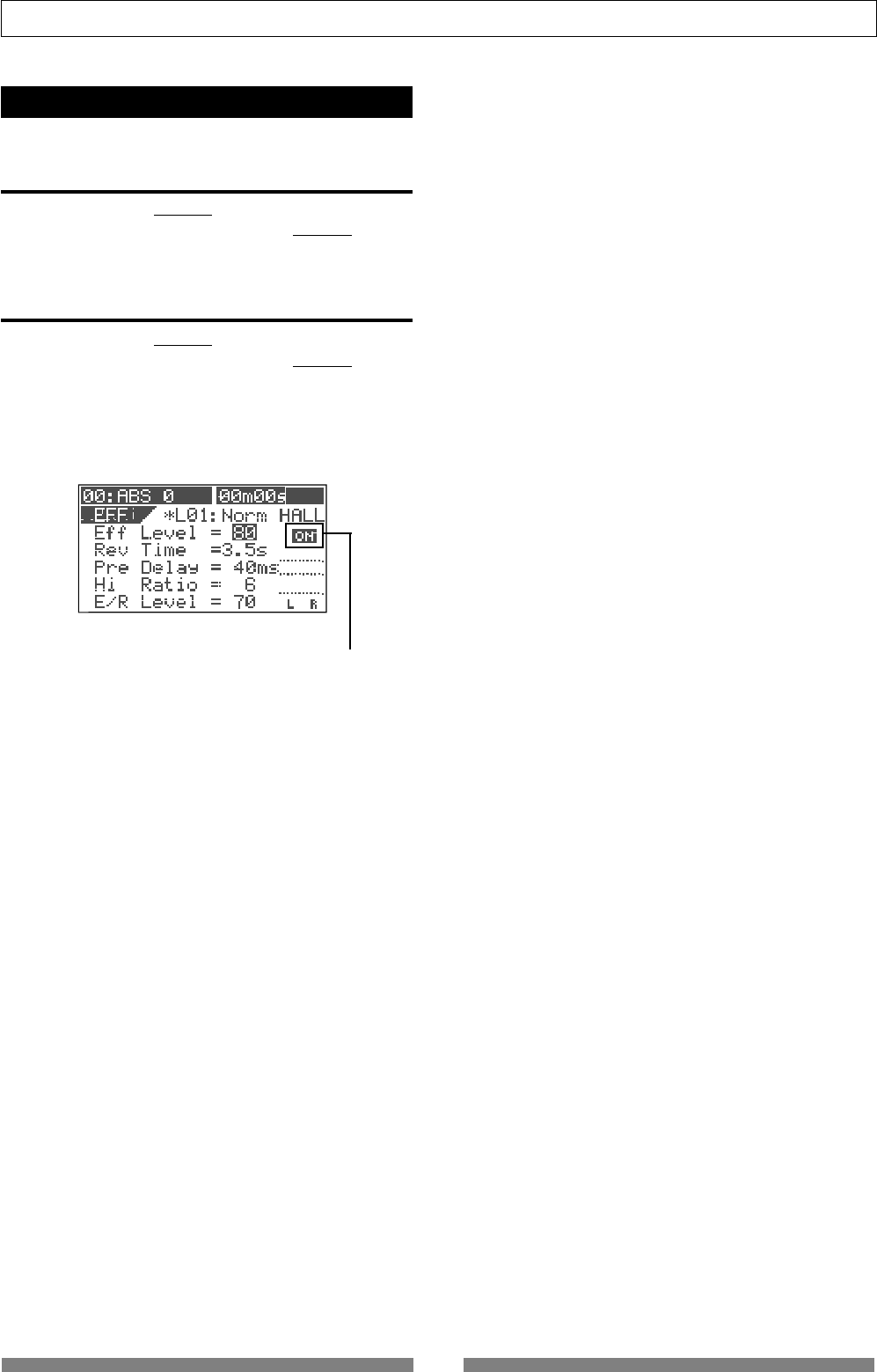
48
Mixer Functions
Turning the effect processor on or off
You can select the on or off of the effect processor.
• To turn on the effect processor
Press the [EFFECT/ON/OFF] key while holding down the
[SHIFT] key to illuminate the [EFFECT/ON/OFF] key.
The effect processor is turned on and you can hear "wet"
sound.
• To turn off the effect processor
Press the [EFFECT/ON/OFF] key while holding down the
[SHIFT] key to illuminate the [EFFECT/ON/OFF] key.
The effect processor is turned off and you can hear "dry"
sound.
You can also see the on/off status of the effect proces-
sor in the effect type/parameter setting screen.
This icon shows the on/off status of the effect processor.
49
Mixer Functions
Name Parameter type Explanation
L01 Norm HALL REVERB Standard hall reverb; detailed and transparent, with a moderate amount of early reflections.
L02 Pres HALL REVERB Hall reverb with presence and definition.
L03 Wet HALL REVERB Hall reverb with restrained high-frequency and a refreshing atmosphere.
L04 NoER HALL REVERB All-purpose hall reverb with no early reflections, and even decay of all frequencies.
L05 Lo-F HALL REVERB Hall reverb with lingering low-frequency reverberation.
L06 STADIUM REVERB Stadium reverb characterized by long early reflections.
L07 AUDITRIUM REVERB Reverb simulating an auditorium with suppressed reverberation.
L08 HALL WAY REVERB Reverb with a long pre-delay, creating the impression of an extended space.
L09 Norm ROOM REVERB Room reverb simulating a moderate space with some sparkle.
L10 Dead ROOM REVERB Room reverb simulating a narrow and dead room. Adding a slight amount will give warmth to the sound.
L11 Pres ROOM REVERB All-purpose room reverb, with good definition and few early reflections.
L12 DrumBOOTH REVERB Room reverb simulating a drum booth.
L13 GARAGE REVERB Room reverb simulating a narrow and live space like a garage, with crisp presence.
L14 NormPLATE REVERB Modern-sounding plate reverb with wide bandwidth.
L15 Old PLATE REVERB Standard plate reverb with the character of older plate units.
L16 PresPLATE REVERB Plate reverb with good definition and extended high-frequencies.
L17 Wet PLATE REVERB Plate reverb with a gentle character.
L18 DigiPLATE REVERB Plate reverb that emphasizes a digital character, with metallic early reflections.
L19 NormVOCAL REVERB All-purpose hall reverb with no early reflections, and uniform decay at all frequencies.
L20 PresVOCAL REVERB Short reverberation with extended high frequency is added to the early reflections of an ideal vocal booth. Since
this adds sparkle to the sound, it is effective when you wish to bring the vocal to the forefront.
L21 SoloVOCAL REVERB Plate-like reverb is added to a spacious short delay. This blends well with any genre of music.
L22 Arena VOC REVERB Gentle reverb is added to spacious stadium-type early reflections.
L23 Arena CHO REVERB Short reverb with extended high frequency is added to spacious stadium-type early reflections. Effective on
chorus parts.
L24 KARAOKE REVERB All-purpose reverb (karaoke style) that makes any vocal sound professional.
L25 MnDL-HALL DLY+REVERB A combined effect of mono delay and hall reverb.
L26 MnDL-PLT DLY+REVERB A combined effect of mono delay and plate reverb.
L27 PnDL-HALL DLY+REVERB A combined effect of panning delay and hall reverb.
L28 PnDL-PLT DLY+REVERB A combined effect of panning delay and plate reverb.
L29 MonoDELAY DELAY Mono delay
L30 PanDELAY DELAY Panning delay
L31 MonoBpmDL BPM DELAY Mono delay. Specify BPM and note value to set the delay time.
L32 PanBpmDL BPM DELAY Panning delay. Specify BPM and note value to set the delay time.
L33 Short DL SHORT DELAY Short delay that allows you to set the delay time precisely.
L34 DOUBLING DOUBLING Doubling that allows you to set separate delay times for L and R.
L35 CHORUS CHORUS Produces a chorus effect. A doubling effect can also be added.
L36 FLANGE FLANGE Produces a flanging effect.
L37 MonoPITCH MONO PITCH Pitch shift adjustable in a +/-2 octave range.
L38 DlyPITCH DELAY PITCH Pitch shift with a feedback delay, allowing strange effects to be produced.
L39 Dist Gtr DISTORTION Distortion sound for a guitar. (See "Advanced Operations" on page 83.)
L40 Dist Bass DISTORTION Distortion sound for a bass. (See "Advanced Operations" on page 83.)
L41 Dist Drum DISTORTION Distortion sound for drums. (See "Advanced Operations" on page 83.)
L42 Dist Voice DISTORTION Distortion sound for a voice. (See "Advanced Operations" on page 83.)
L43 Gtr Amp Sim SIMULATION You can simulates popular guitar amplifier sounds. (See "Advanced Operations" on page 83.)
L44 Mic Sim SIMULATION You can simulates famous microphone sounds. (See "Advanced Operations" on page 83.)
About the effect types
Effect types L01 through L38 are used for the loop effect, while L39 through L44 are used for the insert effect.

50
Mixer Functions
Effect parameter details
The parameters that can be adjusted will depend on the parameter type.
The following describes parameters for effect types L01 through L38 used for the loop effect.
See "Advanced Operations" on page 83 for details about parameters for effect types L39 through L44 used for
the insert effect.
Reverb effect parameters (parameter type: REVERB)
For effect types 1--24 of the preceding "Effect type" table, the following five parameters can be adjusted.
1. Eff Level Adjust the effect return level: 0~99
2. Rev Time Adjust the length of reverberation. Range: 0.1--9.9 seconds
3. Pre Delay Adjust the time from the original sound until reverberation begins. Range: 0--100 ms
4. Hi Ratio Adjust the decay ratio of the high frequencies. Range: 0--10
5. E/R Level Adjust the volume of the early reflections. Range: 0--99
Delay+reverb effect parameters (parameter type: DELAY+REVERB)
For effect types 25--28 of the preceding "Effect type" table, the following five parameters can be adjusted.
1. Eff Level Adjust the effect return level: 0~99
2. Delay Time Adjust the delay time: Range: 1--230 ms
3. Feedback Adjust the number of delay repeats. Range: 0--99
4. Delay Bal Adjust the delay balance. Range: 0--99
5. Rev Time Adjust the length of reverberation. Range: 0.1--9.9 seconds
Delay effect parameters (parameter type: DELAY)
For effect types 29 and 30 of the preceding "Effect type" table, the following five parameters can be adjusted.
1. Eff Level Adjust the effect return level: 0~99
2. Delay Time Adjust the delay time. Range: 1--680 ms
3. Feedback Adjust the number of delay repeats. Range: 0--99
4. Hi Ratio Adjust the decay ratio of the high frequencies. Range: 0--10
5. Filter Adjust the tone of the delay sound. Range: L9~L1, OFF, H1~H9
*L1~L9 = LPF (larger numbers will lower the cutoff frequency)
*H1~H9 = HPF (larger numbers will raise the cutoff frequency)
BPM delay effect parameters (parameter type: BPM DELAY)
For effect types 31 and 32 of the preceding "Effect type" table, the following five parameters can be adjusted.
1. Eff Level Adjust the effect return level: 0~99
2. BPM Adjust the BPM. Range: 30--250 bpm
3. Note Select the note value for the delay. Range: 24, 16, 8T, 16...8, 4T, 8., 4, 2T, 4., 2, 2., 1
*24 = 16th note sextuplets, 16 = 16th notes, 8T = 8th note triplets, 16. = dotted sixteenth notes,
8 = 8th notes, 4T = quarter note triplets, 8. = dotted eighth notes,
4 = quarter notes, 2T = half-note triplets, 4. = dotted quarter notes, 2 = half notes
* The "." shown in the ninth character of the LCD indicates a dotted note.
* The "T" shown in the ninth character of the LCD indicates a triplet.
4. Feedback Adjust the number of delay repeats. Range: 0--99 (100 steps in increments of 1)
5. Filter Adjust the tone of the delay sound. Range: L9~L1, OFF, H1~H9
*L1~L9 = LPF (larger numbers will lower the cutoff frequency)
*H1~H9 = HPF (larger numbers will raise the cutoff frequency)
Short delay effect parameters (parameter type: SHORT DELAY)
For effect type 33 of the preceding "Effect type" table, the following five parameters can be adjusted.
1. Eff Level Adjust the effect return level: 0~99
2. Delay Time Adjust the delay time. Range: 0.1--9.9 ms, 10--99 ms, 100--200 ms
3. Feedback Adjust the number of delay repeats. Range: 0--99
4. Hi Ratio Adjust the decay ratio of the high frequencies. Range: 0--10
5. Filter Adjust the tone of the delay sound. Range: L9~L1, OFF, H1~H9
*L1~L9 = LPF (larger numbers will lower the cutoff frequency)
*H1~H9 = HPF (larger numbers will raise the cutoff frequency)
Doubling effect parameters (parameter type: DOUBLING)
For effect type 34 of the preceding "Effect type" table, the following four parameters can be adjusted.
1. Eff Level Adjust the effect return level: 0~99
2. Lch Delay Adjust the delay time of the L channel. Range: 0.1--9.9 ms, 10--99 ms, 100--200 ms
3. Rch Delay Adjust the delay time of the R channel. Range: 0.1--9.9 ms, 10--99ms, 100--200 ms
4. Filter Adjust the tone of the delay sound. Range: L9~L1, OFF, H1~H9
*L1~L9 = LPF (larger numbers will lower the cutoff frequency)
*H1~H9 = HPF (larger numbers will raise the cutoff frequency)

51
Mixer Functions
Chorus effect parameters (parameter type: CHORUS)
For effect type 35 of the preceding "Effect type" table, the following five parameters can be adjusted.
1. Eff Level Adjust the effect return level: 0~99
2. Depth Adjust the chorus depth. Range: 0--99
3. Double Time Adjust the time difference of the doubling effect. Range: 0--99
4. Double Lvl Adjust the volume of the doubling effect. Range: 0--99
5. Filter Adjust the tone of the delay sound. Range: L9~L1, OFF, H1~H9
* L1~L9 = LPF (larger numbers will lower the cutoff frequency)
* H1~H9 = HPF (larger numbers will raise the cutoff frequency)
Flanger effect parameters (parameter type: FLANGE)
For effect type 36 of the preceding "Effect type" table, the following five parameters can be adjusted.
1. Eff Level Adjust the effect return level: 0~99
2. Rate Adjust the speed of modulation. Range: 0.01--2.00 Hz
3. Depth Adjust the depth of modulation. Range: 0--99
4. Mod Delay Adjust the modulation delay. Range: 0--200
5. Feedback Adjust the number of modulation repeats. Range: 0--99
Delay pitch effect parameters (parameter type: DELAY PITCH)
For effect type 38 of the preceding "Effect type" table, the following five parameters can be adjusted.
1. Eff Level Adjust the effect return level: 0~99
2. Pitct Adjust the amount of pitch shift. Range: -24--0--+24
*+/-12 is one octave. +/-24 is two octaves.
3. Adjust Make fine adjustments to the amount of pitch shift. Range: -50--0--+50
*+50 is a semitone sharp. -50 is a semitone flat.
4. Delay Time Adjust the delay time until the pitch-shifted sound is heard. Range: 0--500 ms
5. Feedback Adjust the number of delay repeats. Range: 0--99
Mono pitch effect parameters (parameter type: MONO PITCH)
For effect type 37 of the preceding "Effect type" table, the following four parameters can be adjusted.
1. Eff Level Adjust the effect return level: 0~99
2. Pitch Adjust the amount of pitch shift. Range: -24--0--+24
*+/-12 is one octave. +/-24 is two octaves.
3. Adjust Make fine adjustments to the amount of pitch shift. Range: -50--0--+50
*+50 is a semitone sharp. -50 is a semitone flat.
4. Mode Select the processing method. Range: 1--3
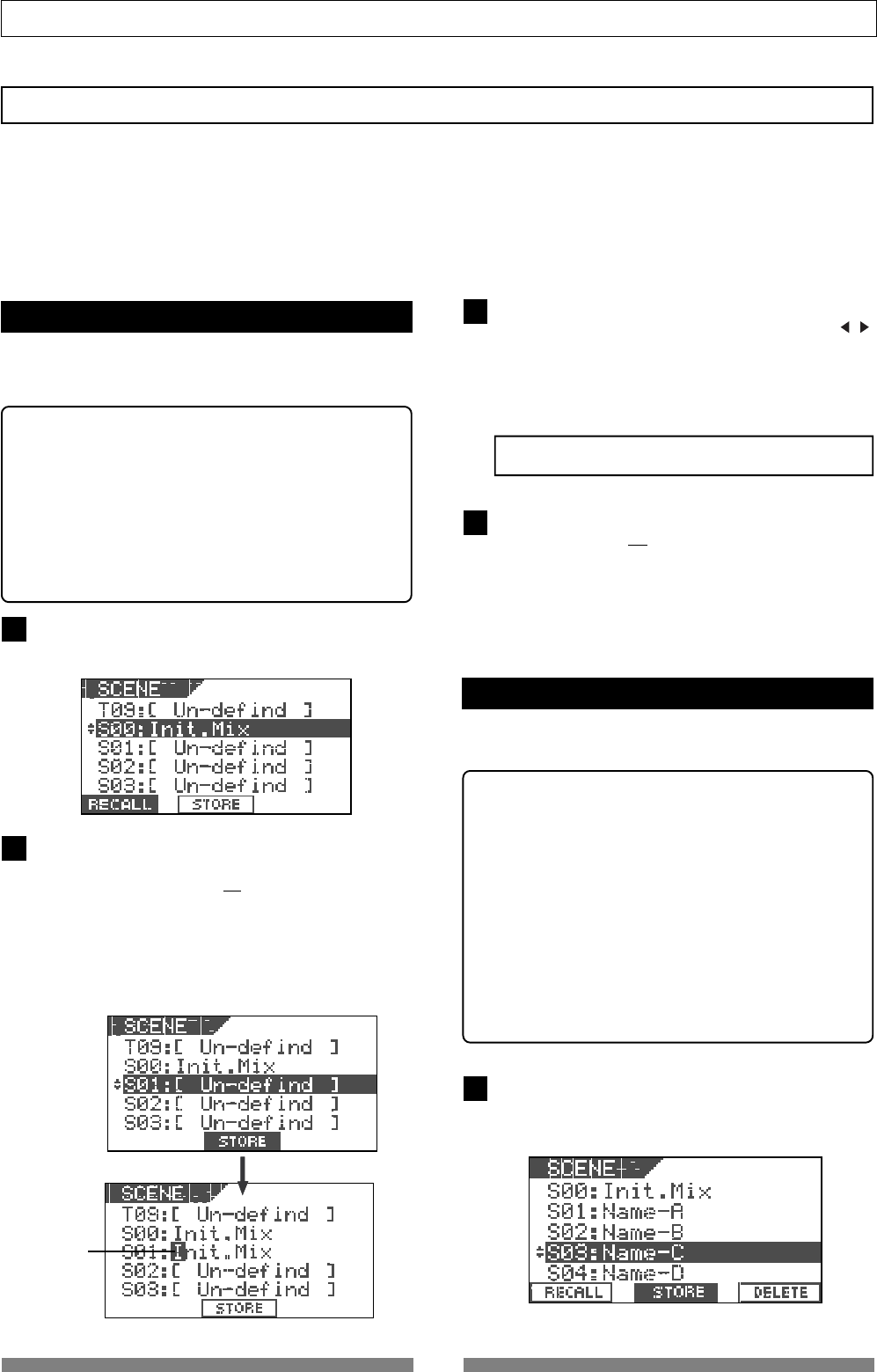
52
Mixer Functions
1
2
3
4
1
Flashing
Scene memory
The VF80 provides 100 Scene memories (S00 to S99) for each program. You can store a set of desired parameter
settings to each memory. Items to be stored include all parameters set by mix parameter editing functions, as
well as all track fader levels. In addition to 100 Scene memories, the VF80 also provides 10 Temporary memories
(T00 to T09) that can be used with all programs in common. Note that all settings stored in Temporary memories
disappear when turning off the power.
You can give a desired title (name) with up to 16 alphanumeric or symbolic characters to each Scene/Temporary
memory. (Note that up to 11 characters can be shown on the display.)
Storing the current scene
You can store the current scene (settings) to a Scene
or Temporary memory by using the following proce-
dure.
<Hint>
Scene memories (shown as S00 through S99 on the list)
are retained even if the power is turned off, while Tem-
porary memories (shown as T00 through T09 on the list)
disappear when the power is turned off, though they do
not disappear when changing the program.
If you want to store a Temporary memory to a Scene
memory (S00 to S99), recall the temporary number be-
fore turning off the power and store the settings to the
desired Scene memory number.
Press the [SCENE] key.
The display shows the screen for selecting the desired
scene number.
Use the [JOG] dial to select the desired scene number
to which you want to store the current settings, and
press the [TIME BASE SEL/F2] key while holding down
the [SHIFT] key. (In the following example, "S01" is
selected.)
The scene name of the program which you worked with
before entering the scene memory mode is duplicated
to the name of the selected scene number, whose
leftmost character flashes, showing that it can be ed-
ited.
Enter the desired scene name by using the [JOG] dial
for selecting a character and using the [CURSOR / ]
keys for moving the editing (flashing) point.
You can specify a scene name with up to 16 alphanu-
meric or symbolic characters and can see up to 14 char-
acters on the display. The following characters can be
entered:
A to Z, a to z, 0 to 9, + - * / # & ! ? ( ) [ ] < > : . , etc.
After completing the scene name entry, press the
[TIME BASE SEL/F2] key while holding down the
[SHIFT] key.
The display changes to the Normal display of the pro-
gram whose scene name has just been set.
Recalling a scene
You can recall the settings stored in Scene or Tempo-
rary memories.
<Cautions>
• If the "
Fader recall On/Off setting
" menu described
later is set to "
OFF"
, when recalling a desired scene
memory, fader settings are not recalled, while "
Scene
Recalled Fader RCL OFF
" is momentarily shown on the
screen.
• If the "
Fader recall On/Off setting
" menu is set to "
ON
",
regardless of the current physical positions of track
and master faders, the audio is output at the fader
positions when they were stored. We suggest you to
turn the monitor volume down when recalling a scene
memory to prevent an accidentally accessing high-
volume sound.
Press the [SCENE] key.
The display shows the screen for selecting the scene
number.
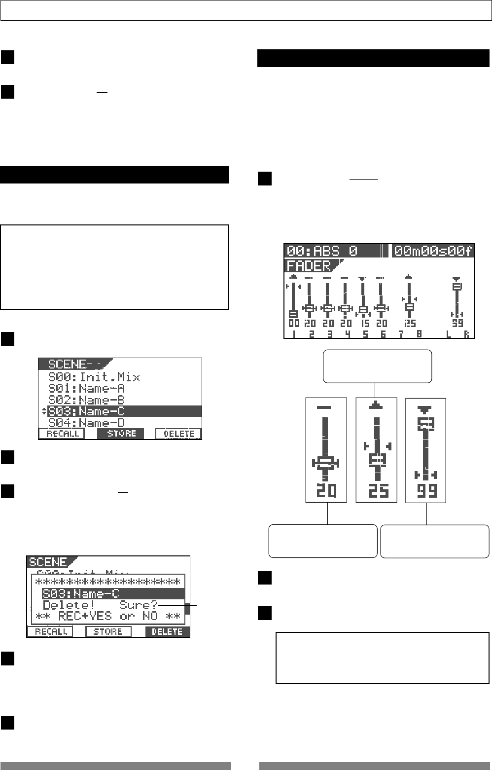
53
Mixer Functions
1
2
3
4
1
2
3
2
3
5
Use the [JOG] dial to select the desired scene number
to be recalled.
Press the [SETUP/F1] key while holding down the
[SHIFT] key.
The selected scene is recalled and the display changes
to the Normal display.
Deleting a scene
You can delete an unnecessary Scene or Temporary
memory by using the following procedure.
<Notes>
• You cannot delete the memory in scene number
00
.
If you select scene number
00
and try to delete the
memory, "
DELETE
" does not appear on the display.
• You cannot undo deleting a scene.
Be sure not to select a wrong scene number to be
deleted.
Press the [SCENE] key.
The display shows the scene number/title list.
Select a memory to be deleted using the [JOG] dial.
Press the [UNDO/REDO/F3] key while holding down
the [SHIFT] key.
The message asking for confirmation to delete the scene
appears and "Sure?" flashes.
To cancel to delete the mark, press the [EXIT/NO] key
now.
Press the [ENTER/YES] key while holding down the
[RECORD] key.
The selected memory is deleted and the scene name
changes to "[Un-defined]", showing that no memory is
stored.
Press the [EXIT/NO] key.
The display returns to the Normal screen.
Fader adjust
After recalling a scene, the recalled fader level usu-
ally does not match the current physical fader posi-
tion, you can move the physical faders to match the
current fader positions of the scene.
The following description is assumed that "Fader re-
call setting" of the setup mode is set to "Trk & Mst."
Press the [SCENE/FADER] key while holding down the
[SHIFT] key.
The display shows the fader setting screen.
The fader icon changes according to the relation be-
tween the physical fader position and recalled fader
position, as show below.
•The current physical fader po-
sition matches the recalled po-
sition.
•The current physical fader po-
sition is higher than the recalled
position.
•The current physical fader po-
sition is lower than the recalled
position.
Move a physical fader manually to match the recalled
(scene memory) position.
After adjusting all the fader positions, press the [EXIT/
NO] key.
<Note>
If you recall a scene when "
Fader recall setting
" of the
setup mode is set to "
OFF
", the current physical fader
positions are valid.
Flashing
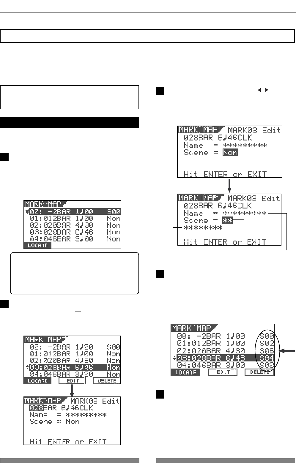
54
Mixer Functions
1
2
3
4
Scene title
Scene number Mark title
5
Scene sequence
Using the scene sequence function, you can recall desired scene memories at the desired mark positions during
playback. For example, you can recall scene memory 02 at "Bar 17/Beat 1" and scene memory 04 at "Bar 25/Beat
1", etc. To execute the scene sequence function, you must first assign scene (or temporary) memories to marks
in the mark map. If you set the timebase to Bar/Beat/Clk, you can assign scene memories to be recalled to the
musical positions (Bar/Beat/Clk numbers). Of course, you may set the timebase to ABS.
<Note>
You must store data to scene memories before assigning
to the mark map.
Assigning scene memories to the mark map
In the following description, we assume that the
timebase is set to Bar/Beat/Clk.
While the recorder is stopped, press the [SCENE SEQ/
MAP] key while holding down the [SHIFT] key.
The screen shows the mark map, in which the current
marks are listed.
In the mark map example below, only scene memory 00
is assigned to mark 00. ("Non" means that no memory is
assigned to the corresponding mark.)
<Hint>
You can view mark titles instead of mark positions
(in bar/beat/clock base or ABS time base) in the mark
map. Pressing the [TIME BASE SEL] key while the mark
map screen is shown switches mark positions and
mark titles.
Select the desired mark using the [JOG] dial, and then
press the [TIME BASE SEL/F2] key while holding down
the [SHIFT] key.
The display shows the screen for editing the selected
mark.
Highlight "Non" using the [CURSOR / ] keys, and
then select the desired scene number to be assigned
to the mark using the [JOG] dial.
When selecting a scene number which holds data, its
scene title is also shown below the scene number.
After selecting the scene number, press the [ENTER/
YES] key.
Repeat steps 1 through 4 to assign scene numbers to
other marks.
In the example below, several scene numbers are as-
signed to marks and you are ready for executing the
scene sequence function described later.
Press the [EXIT/NO] key after assigning all desired
scenes to marks.
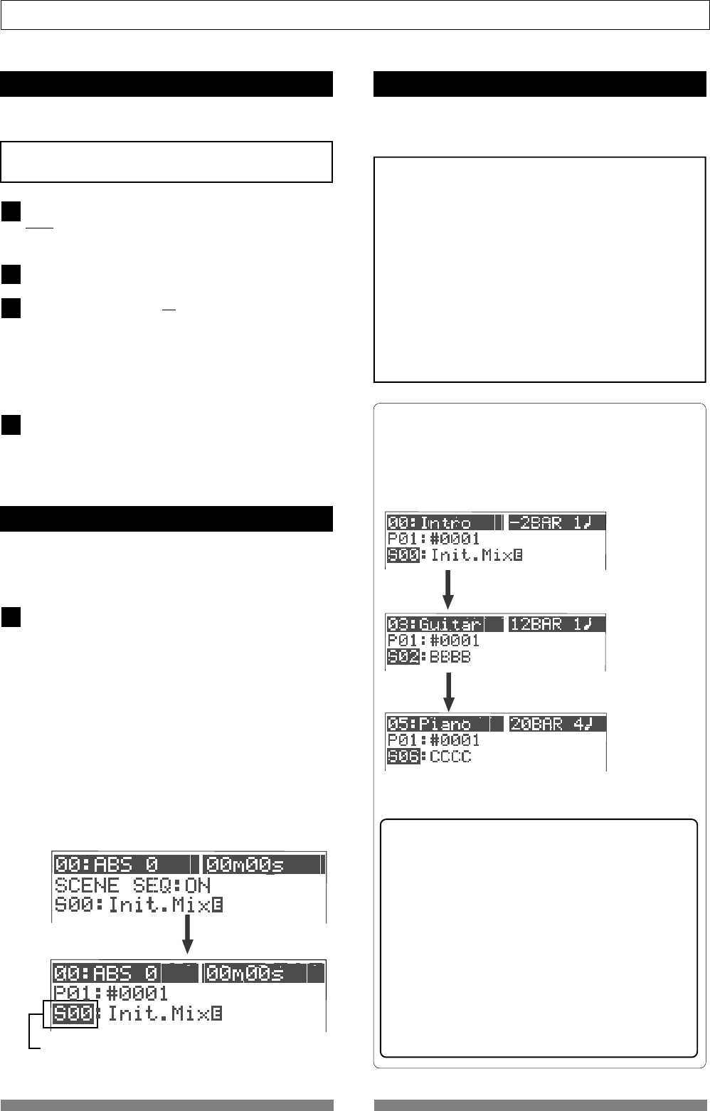
55
Mixer Functions
4
1
2
3
Highlighted
Deleting a mark from the mark map
You can delete an unnecessary mark from the mark
map.
<Note>
You cannot delete
mark 00
.
While the VF80 is stopped, press the [SCENE SEQ/
MAP] key while holding down the [SHIFT] key.
The screen shows the mark map.
Highlight the desired mark using the [JOG] dial.
Press the [UNDO/REDO/F3] key while holding down the
[SHIFT] key.
The message asking for confirmation to delete the mark
appears and "Sure?" flashes.
To cancel to delete the mark, press the [EXIT/NO] key
now.
Press the [ENTER/YES] key while holding down the
[RECORD] key.
The map is deleted and the following marks are renum-
bered.
Scene sequence on/off selection
You can turn on or off the scene sequence function
for selecting whether or not performing the scene
sequence function using the mark map.
While the VF80 is stopped, press the [SCENE SEQ] key.
The [SCENE SEQ] key lights in green, showing that the
scene sequence function is active (ON).
Each time you press the [SCENE SEQ] key, ON and OFF
alternates.
When turning on the scene sequence function, "SCENE
SQ: ON" appears momentarily on the Normal screen and
then the scene number is highlighted.
When turning off the scene sequence function, "SCENE
SQ: OFF" appears momentarily on the Normal screen
and then the highlighted scene number returns to the
Normal screen.
1
Executing the scene sequence
If you start playback while the scene sequence func-
tion is active (ON), the scenes will be recalled accord-
ing to the mark map.
<Note>
When executing the scene sequence, the fader positions
may be recalled or not according to the fader recall mode
setting in the setup mode (the default is "
OFF
").
For example, if you set the fader recall mode to "
ON
", both
the track and master faders are automatically recalled
every time the current scene changes.
On the contrary, if you set the fader recall mode to "
OFF
"
(the default mode), fader positions are not recalled so you
can manually control fader positions as you like.
We suggest you to make sure to set the fader recall mode
suitably for your work before executing the scene se-
quence. See "
Fader recall mode setting
" on page
133
for de-
tails.
<Screen appearances during playback>
The following show the screen appearances during play-
back with the mark map in which scene number 02 (with
the title "BBBB") is assigned to "Bar 12, Beat 1" and scene
number 06 (with the title "CCCC") is assigned to "Bar 20,
Beat 4."
The unit starts playback from "Bar -2, Beat 1" with
the settings stored in scene number 00 (Init Mix).
The unit recalls scene number 02 (BBBB) at "Bar
12, Beat 1" and continues playback.
The unit recalls scene number 06 (CCCC) at
"Bar 20, Beat 4" and continues playback.
<Note>
The effect preset may not be changed while the
scene sequence function is active!
Effect presets of the internal effect processor are clas-
sified into three types; ambience/delay type (No. 1
through 28), modulation/pitch type (No. 29 through
36), pitch type (No. 37 and 38) and distortion/simu-
lation type (No. 39 through 44).
Note that the scene sequence function does not re-
call an effect preset whose type is different from the
current one. This is to avoid momentary audio mut-
ing, and is not a malfunction. The other mix param-
eters of the scene can be recalled even if it includes
an effect preset whose type is different from the cur-
rent one.
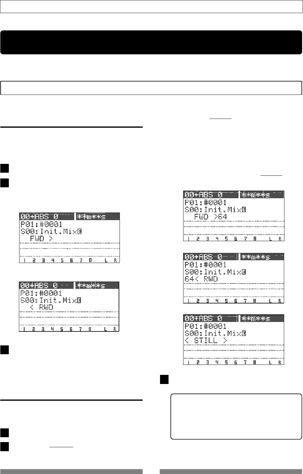
56
Recorder Functions
The VF80 is "cueing" in the forward direction.
The VF80 is "cueing" in the backward direction.
2
1
3
1
2
The VF80 is "cueing" in the forward direction at 64x the normal speed.
3
Recorder Functions
This chapter describes various recorder functions.
Cueing
The cueing function allows you to monitor audio at higher or lower speed.
Cueing with the [F FWD]/[REWIND] keys
By pressing the [F FWD] or [REWIND] key during play-
back, you can monitor (cue) the sound at 3 times the
normal speed.
Press the [PLAY] key to start playback.
Press the [F FWD] or [REWIND] key during playback.
The VF80 starts "cueing" at 3 times the normal speed,
while "FWD" or "RWD" appears on the screen.
To return to the normal playback, press the [PLAY] key.
Shuttle cueing
During playback, "shuttle cueing" is possible at the
speed between 1 and 64 times the normal speed.
Press the [PLAY] key to start playback.
Rotate the [JOG/SHUTTLE] dial while holding down the
[SHIFT] key.
• Rotating the [JOG/SHUTTLE] dial clockwise moves the
position to the forward direction, while rotating the dial
counter-clockwise moves the position to the backward
direction.
• According to the rotating degree, the cueing speed varies
among 1x, 2x, 4x, 8x, 16x, 32x, and 64x.
The current cueing speed is shown on the screen.
• As long as holding down the [SHIFT] key, shuttle cueing
continues even if you release the [JOG/SHUTTLE] dial.
The VF80 is "cueing" in the backward direction at 64x the normal speed.
The VF80 is still.
To return to the normal playback, press the [PLAY] key.
<Remember!>
Once the data is rewound to the beginning of a pro-
gram (ABS 0), playback starts from the beginning of
the program, regardless of pressing the [SHIFT] key.
When reaching the end of a program (ABS: 23H 59M
59S), the program stops and the [PLAY] hey flashes.
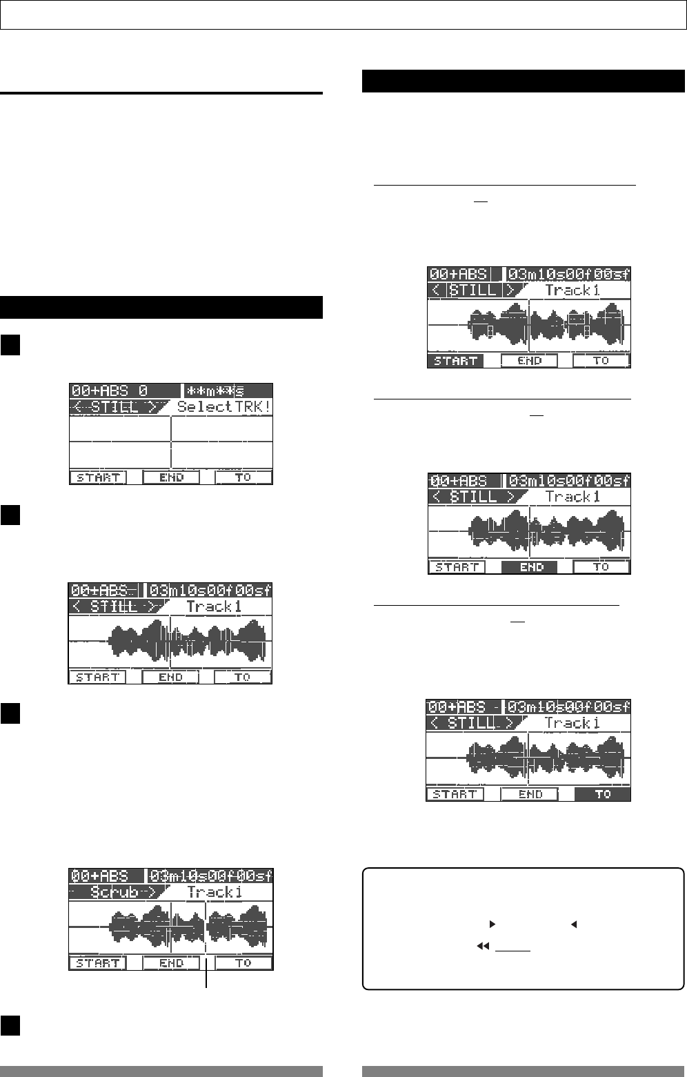
57
Recorder Functions
current scrubbing position
4
3
2
1
Digital scrubbing
Digital scrubbing can be done between 0x and 1x
speed without changing the pitch while the VF80 is
stopped.
You can scrub audio track by track. The level enve-
lope of the scrub track is shown on the screen, allow-
ing you to locate the beginning of a song or interval
of songs easily.
Furthermore, you can use the position located by
digital scrubbing as an edit point for the track editing
or auto-punch in/out.
Performing digital scrubbing
While stopped, press the [WAVE FORM SCRUB] key.
The VF80 enters the scrub mode, and the display shows
the screen below.
Press the [TRACK STATUS/TRACK SEL] key for the
track you are going to scrub.
The level envelope of audio recorded on the selected
track is shown. When the VF80 is stopped, "<STILL>" is
also shown.
By rotating the [JOG] dial, you can scrub audio of the
selected track.
The vertical line in the center shows the current posi-
tion, and you can hear scrubbing audio from this posi-
tion to either the forward or backward direction.
When rotating the [JOG] dial clockwise, "Scrub >" is
shown. When rotating the [JOG] dial counter-clockwise,
"< Scrub" is shown.
The cursor (the vertical line) moves while scrubbing,
while the time value (or bar/beat) of the current posi-
tion is shown in realtime.
If you want to scrub another track, repeat steps 2 and 3.
Storing the digital scrub point
You can store the scrub point to the Start, End or To
point for track editing functions (such as Copy, Move,
Paste and Erase), or the auto-punch in point.
• To store the scrub point to the Start point:
Press the [SETUP/F1] key while holding down the [SHIFT]
key.
"Edit Start Point Stored!" is shown briefly and then the
scrub point is stored to the Start point for track editing.
• To store the scrub point to the End point:
Press the [TIME BASE SEL/F2] key while holding down
the [SHIFT] key.
"Edit End Point Stored!" is shown briefly and then the scrub
point is stored to the End point for track editing.
• To store the scrub point to the To point:
Press the [UNDO/REDO/F3] key while holding down the
[SHIFT] key.
"Edit To Point Stored!" is shown briefly and then the scrub
point is stored to the To point, which can be used as the
starting point of Paste or the auto-punch In point.
• After storing the point, press the [EXIT/NO] key.
The display returns to the Normal screen that was shown
when finishing scrubbing.
<Hint>
• You can also store the point by pressing the [ENTER/
YES] key after highlighting “START”, “END” or “TO” by
using the [CURSOR ] or [CURSOR ] key.
• By pressing the [| / MARK] key while holding down
the [SHIFT] key, you can store the scrub point to a mark
memory.
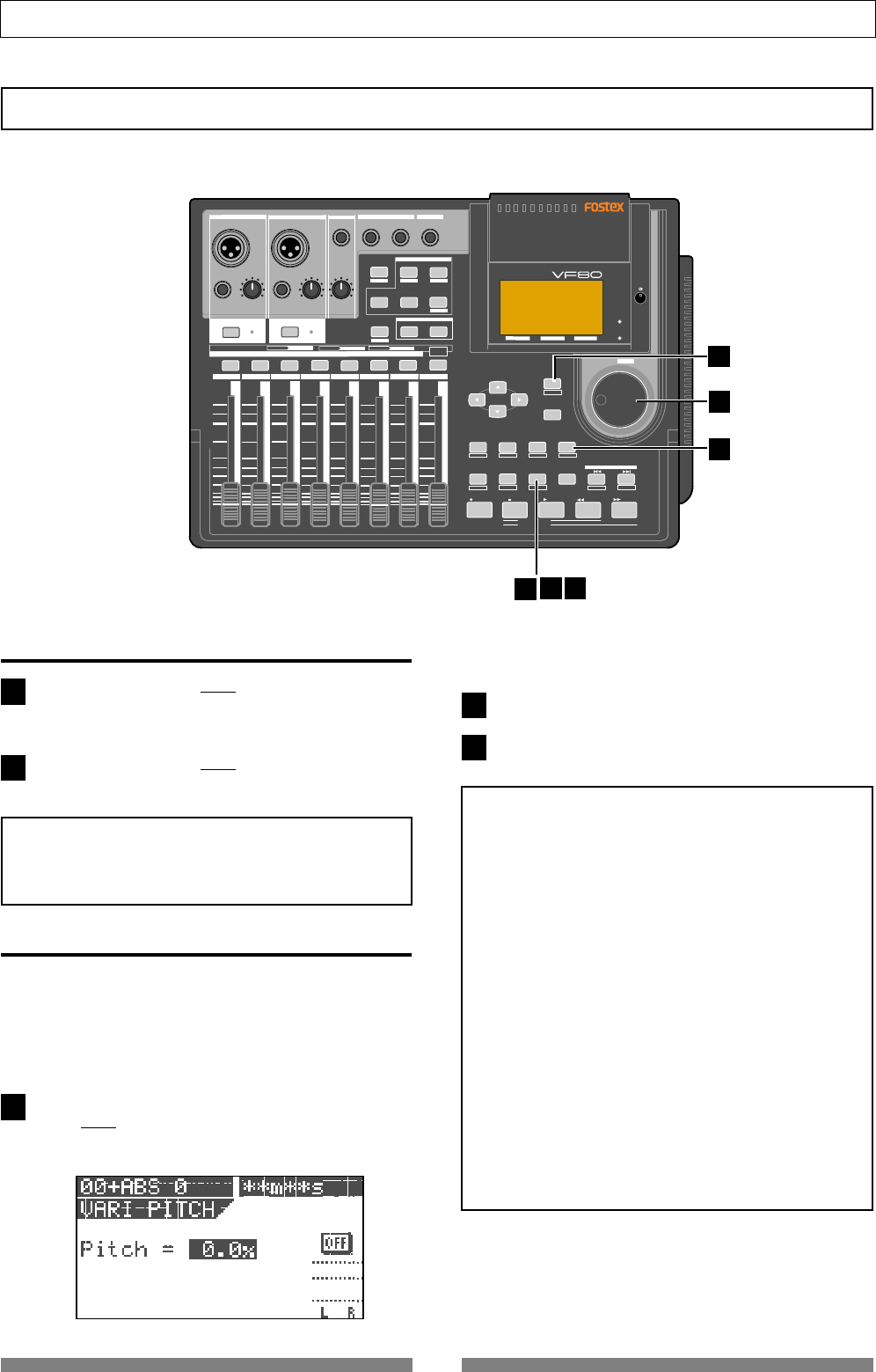
58
Recorder Functions
DIGITAL MULTITRACKER
LOCATE ABS 0
LOCATE REC END
SEL
TIMEBASE
CURSOR
PHANTOM
ACCESS
PEAK
CH ON/OFF
LR
GUITAR
GUITAR
LINE MIC LINE MIC MIN MAX
MASTERING TRAINING
EFFECTEQPAN
SCENE SEQ.SCENE
TRACK
UNDO
SETUP
PUNCH
AUTO LOOP PITCH SCRUB
VARI
F FWDREWINDPLAYSTOPRECORD
EXIT
ENTER
TRIMTRIM
WAVE FORM
MIX PARAMETER
PGM FADER MAP
ON/OFF
2TRK MODE
F1 F2 F3 SHIFT
EDIT EDIT EDIT MARK DELETE
LOCATE
FOOT SW
ST OUT
PHONES
INPUT A
BOUNCE
INPUT B
+6
-10
-20
-40
-
∞
-30
0
+6
-10
-20
-40
-
∞
-30
0
+6
-10
-20
-40
-
∞
-30
0
+6
-10
-20
-40
-
∞
-30
0
+6
-10
-20
-40
-
∞
-30
0
+6
-10
-20
-40
-
∞
-30
0
+6
-10
-20
-40
-
∞
-30
0
+6
-10
-20
-40
-
∞
-30
0
PEAK
CH ON/OFF
2345 6 7/8 2TRK1 MASTER
TRACK STATUS / TRACK SEL
TRACK STATUS
RED REC GREEN PLAY OFF MUTE STATUS
/SEL
EJECT
/YES
/NO
SHUTTLE
JOG
UNBAL UNBAL
BAL
BAL
F1 F2 F3
EDIT
/REDO
REC EFF
123
3
4
5
4
5
1
2
1
Vari Pitch
You can alter the playback or recording speed of the recorder within +/- 6.0 % range in 0.1 % increments/dec-
rements by using the vari pitch function. With the vari pitch function, the pitch changes according to the speed.
Turning on or off the vari pitch function
Press the [VARI PITCH/EDIT] key.
The key lights up in green, showing the vari pitch func-
tion is active.
Press the [VARI PITCH/EDIT] key again.
The key turns off, showing the vari pitch function is not
active.
<Note>
You can turn on or off the vari pitch function while
stopped or during playback, however, you cannot turn
on or off the function during recording.
Setting the speed
You can adjust the speed while stopped or during
playback, however, you cannot adjust the speed dur-
ing recording. If you adjust the speed during play-
back with the vari pitch function active, you can moni-
tor the result of speed (pitch) change while adjusting.
While stopped or during playback, press the [VARI
PITCH/EDIT] key while holding down the [SHIFT] key.
The current pitch value is highlighted, showing that the
value can be edited.
"ON" or "OFF" (of the vari pitch function) is also shown
on the screen.
Use the [JOG] dial to enter the pitch value.
Press the [EXIT/NO] key to return to the Normal screen.
<Notes>
• Even if the pitch value is set to 0.0 % (no speed
change), pressing the
[VARI PITCH]
key turns on the
vari pitch function.
In such a condition, the function is active but the
speed is not changed.
• The vari pitch function automatically turns off by
carrying out any of the following.
1.Turning the power off and then on. (The pitch
value is also reset to 0.0 %.)
2.Setting the slave mode to "On" in the setup mode.
(The pitch value is retained.)
Note that you cannot turn on the vari pitch
function when the slave mode is "On".
3.Setting the digital input to "On" in the setup mode
("DIGI IN" is shown on the screen).
Note that you cannot turn on the vari pitch
function when the digital input is selected.
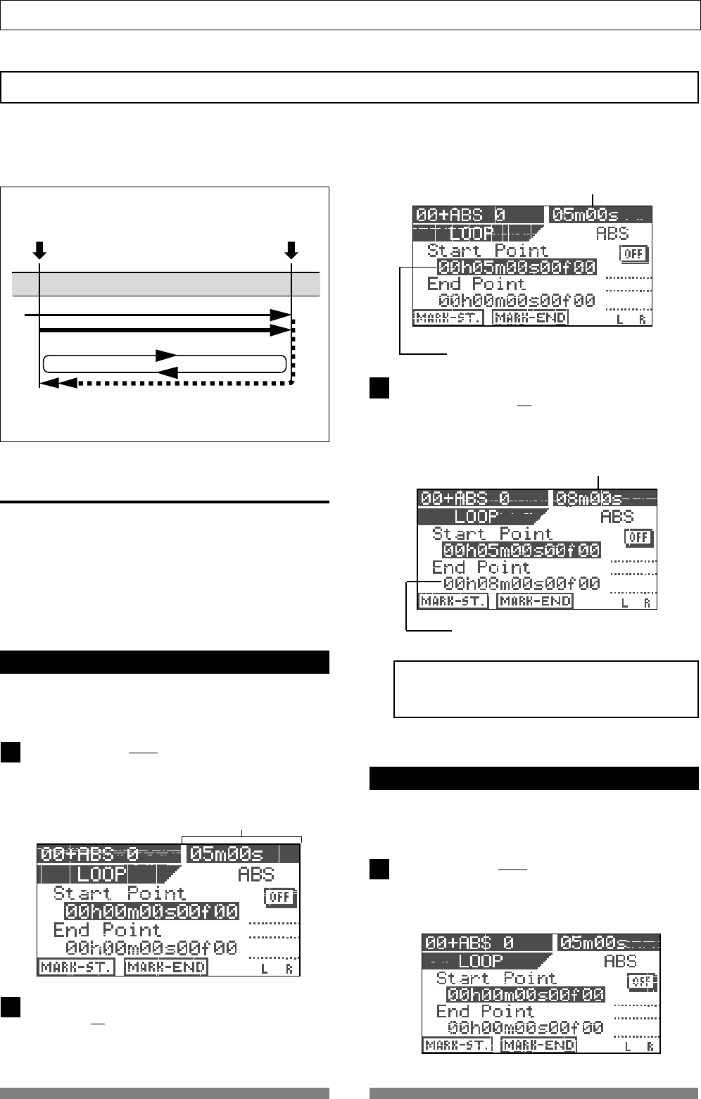
59
Recorder Functions
<Loop Function>
Current time (or musical position)
The Start point is set to the captured time (or musical
position), which is shown here.
The End point is set to the captured time (or musical po-
sition), which is shown here.
Current time (or musical position)
1
3
1
2
Loop Function
After locating the Start point, playback starts automatically.
When the playback position reaches the End point,
the recorder locates to the Start point automatically.
START point
Playback
END point
Using the loop function, you can repeat the desired part between the Start and End points.
By using the loop function together with the punch in/out or training mode, you can concentrate on playing
without the need for operating the VF80.
Setting the Start and End points
There are following three methods for setting the Start
and End points.
1. Capturing the current position "On-the-fly"
2. Editing the time (or musical position) via the screen
3. Setting by marks
Capturing the current position "on-the-fly"
While stopped or running, you can set the Start or End
point at the point you capture.
Press the [LOOP/EDIT] key while holding down the
[SHIFT] key.
The display shows the loop screen in which you can set
the Start and End points.
At the point where you want to set the Start point, press
the [SETUP/F1] key while holding down the [SHIFT] key.
"Start Point Stored!" briefly appears and the Start point
is set to the captured point.
Current time (or musical position)
At the point where you want to set the End point, press
the [TIME BASE SEL/F2] key while holding down the
[SHIFT] key.
"End Point Stored!" briefly appears and the End point is
set to the captured point.
<Note>
The Start point must be earlier than the End point.
Otherwise, the loop function cannot be performed.
Editing the position via the screen
In the following description, the recorder is assumed
to be stopped and the ABS time base is selected.
Press the [LOOP/EDIT] key while holding down the
[SHIFT] key.
The display shows the loop screen in which you can set
the Start and End points.
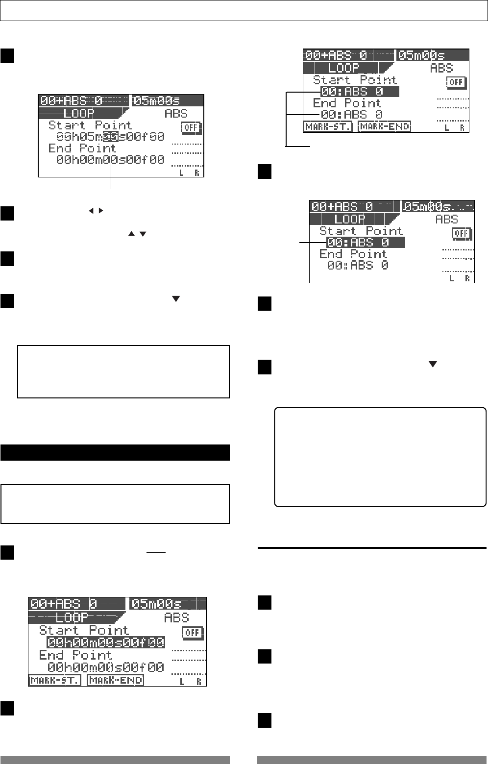
60
Recorder Functions
The "seconds" value flashes.
A mark is shown.
Flashing
1
2
3
4
5
3
2
3
4
5
1
2
To edit the Start point, press the [ENTER/YES] key while
"Start Point" value is highlighted.
The "seconds" value flashes, showing that it can be ed-
ited.
Use the [CURSOR / ] keys to move the flashing value,
and use the [JOG] dial to edit the value.
You can also use the [CURSOR / ] keys to edit the value.
After editing all values, press the [ENTER/YES] key.
The display returns to the similar screen shown in step
1 above, in which the Start point is set to the edited time.
To edit the End point, use the [CURSOR ] key to high-
light the "End point" value and carry out the same
operations as steps 2 through 4 above.
<Note>
As also noted in "
capturing the current position on-the-
fly
", the Start point must be earlier than the End point.
Otherwise, the loop function cannot be performed.
Setting the Start and End points by marks
You can set the Start and End points by marks.
<Note>
This method only can be used when any mark point is
already stored.
While stopped, press the [LOOP/EDIT] key while hold-
ing down the [SHIFT] key.
The display shows the loop screen in which you can set
the Start and End points.
Press the [TIME BASE SEL] key.
Both the Start point and End point value fields show a
mark (number and name).
Press the [ENTER/YES] key.
The mark shown on the Start point value field starts
flashing.
Use the [JOG] dial to select the desired mark and press
the [ENTER/YES] key.
The Start point is set to the selected mark, while the
display returns to the similar screen shown in step 2
above.
To edit the End point, use the [CURSOR ] key to high-
light the "End point" value and carry out the same
operations as steps 3 through 4 above.
The selected mark is set to the End point.
<Hint>
When rehearsing the auto punch in/out, if you also
activate the loop function in which the Start point is
set to a point a little bit earlier than the In point while
the End point is set to a point a little bit later than the
Out point, you can rehearse the auto punch in/out
repeatedly as many times as you like.
The loop function is also useful when you make a prac-
tice using the training mode.
Carrying out the loop playback
Once setting the Start and End points, you can carry
out the loop function.
Press the [LOOP] key to illuminate the key.
The loop function is now active.
Each time you press the [LOOP] key, On and Off of the
loop function alternates.
Start playback from the point earlier than the Start point.
When the recorder reaches the End point, it automati-
cally locates to the Start point and starts playback from
that point. The recorder continues loop playback until
stopping the recorder.
To stop loop playback, press the [LOOP] key to turn off
the lamp and press the [STOP] key.
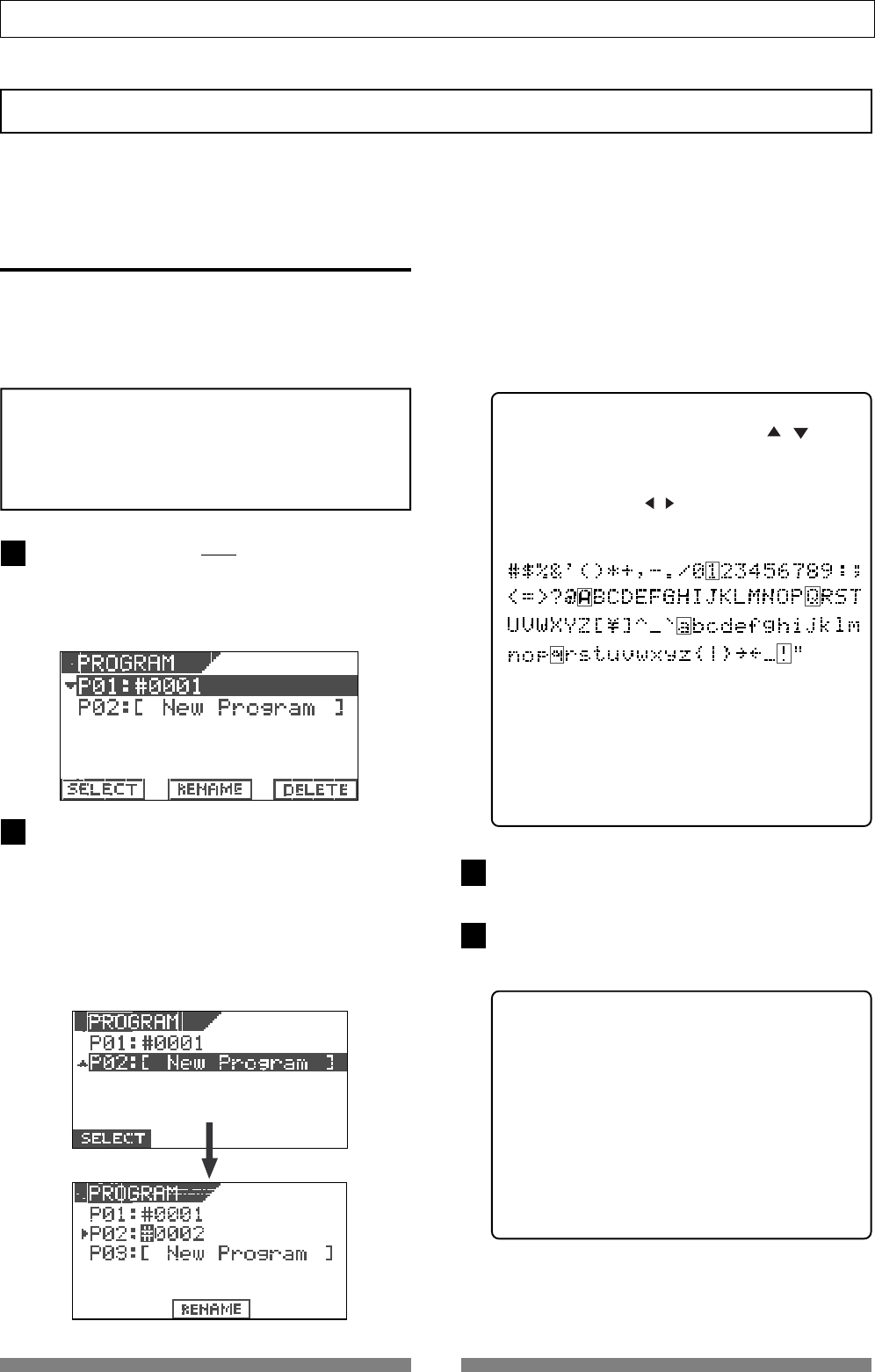
61
Recorder Functions
3
4
1
2
Program
The VF80 can have up to 99 programs (P01 through P99) and usually each program manages one song.
You can make recording against each program or playback materials recorded on each program.
This section describe program-related operations.
Creating a new program
When formatting a hard disk, a program (P01) is au-
tomatically created.
To create a new program, follow the procedure below
while the recorder is stopped and the display shows
the Normal screen.
<Note>
The initial settings for a new program are copied from the
setting of the current program.
Therefore, if you want to make a new program with the
same settings as an existing program, bring up the pro-
gram before creating a new program.
Press the [TRACK EDIT/PGM] key while holding down
the [SHIFT] key.
The screen for selecting, renaming or deleting a pro-
gram appears. (The screen example below shows the
initial condition where only Program 01 exists.)
Use the [JOG] dial to highlight "P02 [New Program]"
and then press the [ENTER/YES] key.
When highlighting "P02 [New Program]", only high-
lighted "SELECT" is shown at the bottom of the screen.
Pressing the [ENTER/YES] key creates a new program
(P02 in this example) with the tentative title whose
leftmost character ("#" in this example) is highlighted.
In this condition, you can enter the program title by
following the procedure described in "<How to enter a
desired title> below.
Note that you may use the program with the tentative
title ("#0002" in this example) if you do not need to en-
ter the desired one. Anyway, you may also enter/edit
the title later by the procedure described in "Editing a
program title" on page 62.
To use the program with the tentative title, press the
[EXIT/NO] key. To put the desired title, see the following.
<How to enter a desired title>
• Rotate the [JOG] dial (or [CURSOR / ] keys)
to select a character for the blinking point from
among those listed below.
• Use the [CURSOR / ] keys to move the blinking
point.
<Hint>
When selecting a character, rotating the [JOG] dial
while holding down the [SHIFT] key jumps among
characters surrounded with the box above.
This function will allow you to save time for select-
ing a desired character.
Press the [ENTER/YES] key after entering the title.
The title is set.
Press the [EXIT/NO] (or [STOP]) key.
The setup mode exits and the display shows the Nor-
mal screen of the newly created program.
<Hint>
• When creating a new program, the next program
number to the highest program number in the
existing programs is assigned.
If there is only one program (P01), Program 02
(P02) will be created. If there is five programs (P01
through P05), Program 06 (P06) will be created.
• Creating a new program consumes a small amount
of the recordable disk space. Also note that when
the recordable disk space is not enough, you
cannot create a new program.
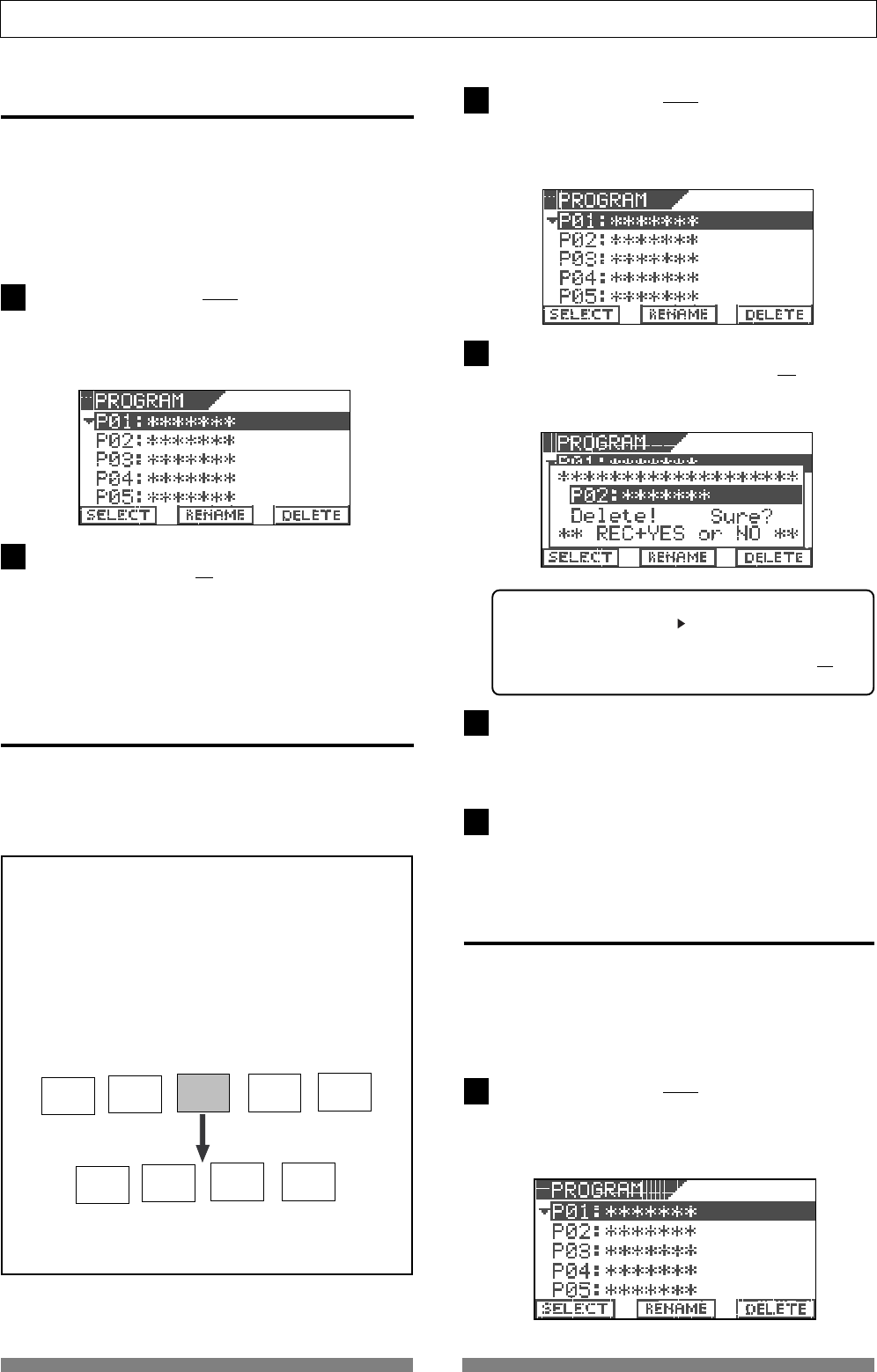
62
Recorder Functions
P01 P02 P03 P04 P05
P01 P02 P03 P04
P03 is deleted.
1
3
4
1
2
1
2
Selecting a program
When more than one program exists on the disk, you
have to select the desired program before starting
operations for recording, playback or editing.
Select the desired program by following the procedure
below while the recorder is stopped and the display
shows the Normal screen.
Press the [TRACK EDIT/PGM] key while holding down
the [SHIFT] key.
The screen for selecting, renaming or deleting a program
appears. In the screen, all existing program numbers
and titles are shown.
Use the [JOG] dial to highlight the desired program and
then press the [SETUP/F1] key while holding down the
[SHIFT] key.
Deleting a program
You can delete an unnecessary program individually.
To make recording or editing, a certain amount of disk
space is needed. By deleting unnecessary programs,
the available disk space increases.
<Notes>
• When only one program (P01) exists, if you try to
delete the program, the data in the program is deleted
but P01 remains.
• For example, when five programs (P01 through P05)
exist, if you delete P03, it looks like P05 is deleted. This
is because the program numbers higher than 03 move
down. In other words, P04 and P05 become P03 and
P04 respectively.
Note that you cannot undo or redo deleting the program.
Press the [TRACK EDIT/PGM] key while holding down
the [SHIFT] key.
The screen for selecting, renaming or deleting a program
appears. In the screen, all existing program numbers
and titles are shown.
Use the [JOG] dial to highlight the program to be de-
leted and then press the [UNDO/REDO/F3] key while
holding down the [SHIFT] key.
The screen shows "Delete! Sure?", asking you confirm.
<Hint>
You may use the [CURSOR ] to highlight "DELETE" and
press the [ENTER/YES] key to bring up the screen
above, instead of pressing the [UNDO/REDO/F3] key
while holding down the [SHIFT] key.
Press the [ENTER/YES] key while holding down the
[RECORD] key.
The selected (highlighted) program is deleted, and the
following programs in the list move up.
Press the [EXIT/NO] key to switch to the Normal screen.
The previous program of the deleted program is se-
lected.
Editing a program title
You can edit a program title anytime by following the
procedure below.
Note that you can also enter a program title in the
process of creating a new program as mentioned ear-
lier.
Press the [TRACK EDIT/PGM] key while holding down
the [SHIFT] key.
The screen for selecting, renaming or deleting a program
appears. In the screen, all existing program numbers
and titles are shown.
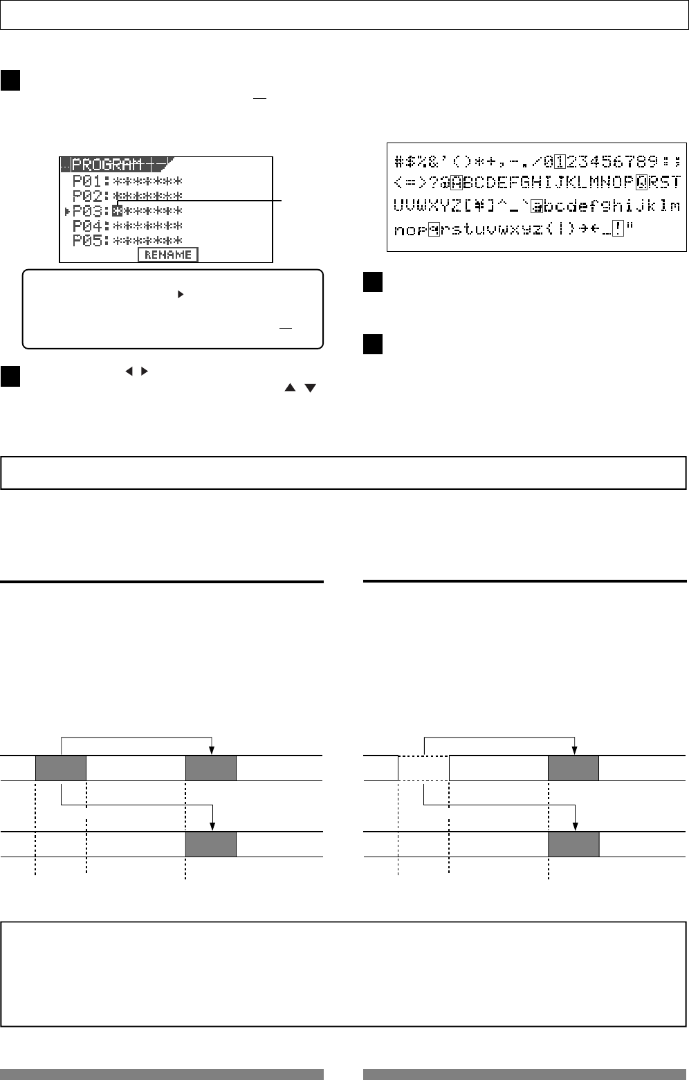
63
Recorder Functions
4
3
2
5
Use the [JOG] dial to highlight (select) the desired pro-
gram and then press the [TIME BASE SEL/F2] key while
holding down the [SHIFT] key.
Now you can edit the title of the selected program.
The leftmost character of the selected program is flash-
ing.
<Hint>
You may use the [CURSOR ] to highlight "RENAME"
and press the [ENTER/YES] key to bring up the screen
above, instead of pressing the [TIME BASE SEL/F2] key
while holding down the [SHIFT] key.
Use the [CURSOR / ] keys to move the flashing (ed-
iting) point and use the [JOG] dial (or [CURSOR / ]
keys) to select a character for the flashing point.
You can put a title name with up to 16 characters from
among those listed below.
When selecting a character, rotating the [JOG] dial while
holding down the [SHIFT] key jumps among characters
surrounded with the box below.
Press the [ENTER/YES] key after editing/entering the
title.
The edited/entered title is set.
Press the [EXIT/NO] (or [STOP]) key.
The display returns to the Normal screen.
Track editing
Because the VF80 uses a 3.5-inch E-IDE hard disk as the recording media, you can make non-linear and non-
destructive audio editing by track effectively.
Copy & Paste
The Copy & Paste function allows you to copy track
data of a desired part and paste it to a desired part of
the same or different track.
The copied data remains after pasting the data, so you
can paste the data as many times as required.
The copy & paste function is useful when using the
same musical part repeatedly in a song.
Move & Paste
The Move & Paste function allows you to move track
data of a desired part and paste it to a desired part of
the same or different track.
Unlike the copy & paste operation, the moved data
does not remain in the original position.
<Notes>
• Copy data (or Move data) is replaced with the new data every time the copy (or move) operation is carried out.
• Note that copy data changes if you paste the copy data to the original data.
• The copy & paste (or move & paste) editing is performed on the current program. Therefore, do not change the current
program until the editing operations are completed.
AA'
A'
START Point END Point TO Point
Copy & paste within the same track.
Copy & paste between different track.
AA'
A'
START Point END Point TO Point
Move & paste within the same track.
Move & paste between different track.
Flashing
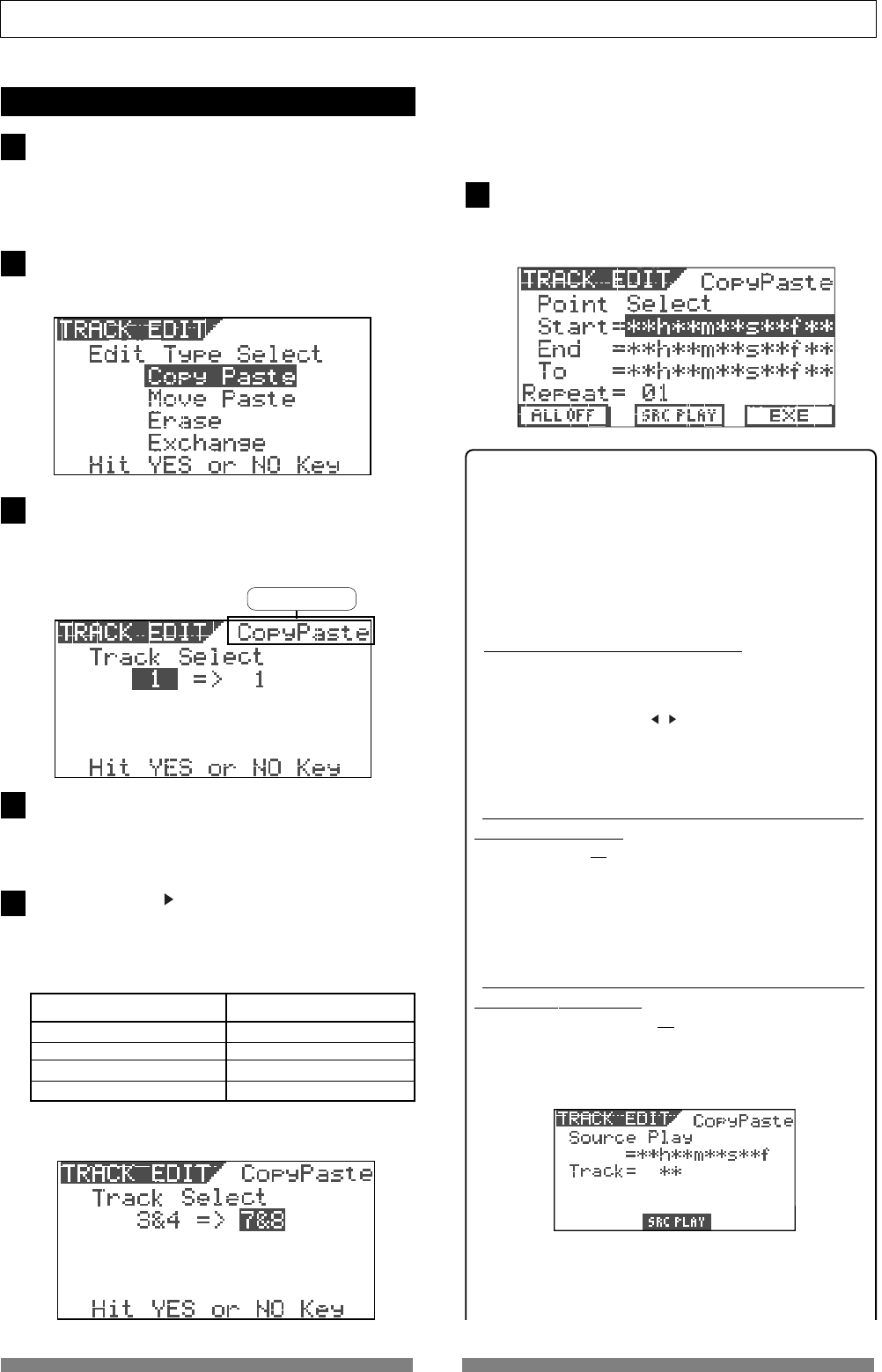
64
Recorder Functions
or "MovePaste"
6
1
2
3
4
5
Performing Copy (or Move) & Paste
Set the Start and End points for the copy (or move)
operation and To point for the paste operation.
Using the digital scrub function, set the Start, End and
To points. See "Storing the digital scrub point" for details
about how to set the points.
While the recorder is stopped, press the [TRACK EDIT]
key.
The screen for selecting the track edit type appears.
Use the [JOG] dial to select "Copy Paste" (or "Move
Paste") and then press the [ENTER/YES] key.
The display shows the screen for selecting the source
track(s) and destination track(s).
Use the [JOG] dial to select the source track(s) from
which the data is copied (moved).
Rotating the [JOG] dial changes the options among 1
through 8, 1&2, 3&4, 5&6, 7&8, 1-6, and 1-8.
Use the [CURSOR ] key to highlight (and flashes) the
right field, and use the [JOG] dial to select the destina-
tion track(s) to which the data is copied (moved).
Rotating the [JOG] dial changes the options as below
depending on the track(s) you selected in step 4.
Source track(s) Destination options
a mono track (1 through 8) 1 through 8
a pair of tracks 1&2, 3&4, 5&6, and 7&8
1-6 1-6 only
1-8 1-8 only
In the example below, data on tracks 3&4 is copied (or
moved) and pasted onto tracks 7&8.
The corresponding [TRACK STATUS/TRACK SEL] keys of
the source track(s) light in green, while the correspond-
ing [TRACK STATUS/TRACK SEL] keys of the destination
track(s) light in red.
Press the [ENTER/YES] key after selecting tracks.
The display shows the "Point Select" screen as below, in
which you can view the Start, End and To points set via
the digital scrub operation.
<Hints>
On the screen above, you can perform the following
operations.
1. Editing the Start, End and To points
2. Setting the Start and To points to "ABS 0" and the End point
to "REC END"
3. Checking the data to be copied (or moved)
4. Setting the Start, End and To points by marks
• To edit the Start, End and To points:
Highlight the time field of the desired (Start, End or To) point,
and then press the [ENTER/YES] key.
The "seconds" value starts flashing, showing that you can
edit it. Use the [CURSOR / ] keys to move the flashing
value, and use the [JOG] dial to enter a value.
After entering the desired time, pressing the [ENTER/YES]
key to store the time data to the point.
• To set the Start and To points to "ABS 0" and the End
point to "REC END":
Press the [SETUP/F1] key while holding down the [SHIFT] key.
"ALL OFF" changes to "ALL ON", and the Start and To
points are set to "ABS 0", while the End point is set to "REC
END" point. This function is useful when you copy (or
move) all track data (from "ABS 0" to "REC END") to dif-
ferent track(s).
• To check (monitor) the data to be copied (or moved)
[Source Play function]:
Press the [TIME BASE SEL/F2] key while holding down the
[SHIFT] key.
The display shows the "Source Play" screen as shown
below and the recorder starts playback of the data to be
copied (or moved).
You can hear audio by moving up the corresponding track
fader. After checking audio, press the [STOP] key.
The display returns to the screen shown before perform-
ing the Source play function.
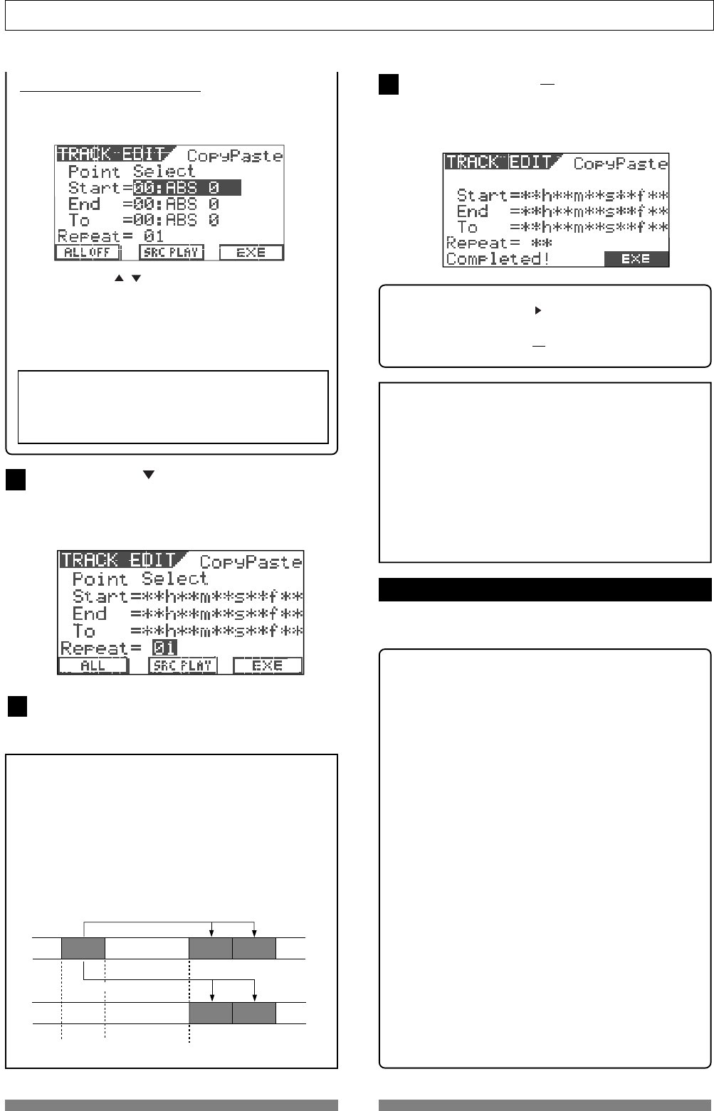
65
Recorder Functions
7
8
6
• To set editing points by marks:
Press the [TIME BASE SEL] key.
Each data field for the Start, End and To points changes
to show the current option by mark as shown below.
Use the [CURSOR / ] keys to highlight the field for the
desired point, and press the [ENTER/YES] key.
The field starts flashing.
Use the [JOG] dial to select the desired mark and press
the [ENTER/YES] key.
The point is set to the selected mark.
<Note>
This operation can be performed only when any mark
is set. When no mark is set, "
00:ABS 0
" is the one and
only option for each point.
Use the [CURSOR ] key to highlight the field ("01"
above) for the number of times for repeat paste, and
press the [ENTER/YES] key.
"01" starts flashing and you can now enter the number
of times for repeat paste.
Use the [JOG] dial to select the desired number and
press the [ENTER/YES] key.
You can select any number between "01" and "99".
<Note>
Basically you can select the number of times for repeat
paste between 1 and 99, however, if the recordable space
of the hark disk is limited, you may not be able to select
the desired number. The VF80 automatically calculate
the available space and limit the number of times to the
appropriate value.
When setting the number of times for repeat paste to 02,
the copy & paste function is performed as below.
A''
A''
AA'
A'
START Point END Point TO Point
Copy & paste within the same track.
Copy & paste between different track.
Press the [UNDO/REDO/F3] key while holding down the
[SHIFT] key.
The copy & paste (or move & paste) function is per-
formed. When finished, "Completed!" appears on the
screen.
<Hint>
You may use the [CURSOR >] to highlight "EXE" and press
the [ENTER/YES] key to perform the function, instead of
pressing the [UNDO/REDO/F3] key while holding down the
[SHIFT] key.
<Note>
The copy & paste (or move & paste) operation cannot be
performed when there is not enough disk space to per-
form the undo and redo operations. If you try to perform
the paste operation when there is not enough disk space,
The display will show "
Over Time!
", as well as the short
time.
In such a case, shorten the copy (or move) data by the
amount more than the displayed time or delete unnec-
essary sections or programs to keep the enough space,
and then try to paste again.
Undo/redo of Copy & Paste
You can undo a copy & paste or move & paste opera-
tion, as well as redo it (undo the undo operation).
• By pressing the [UNDO/REDO] key after completing the
copy & paste (or move & paste) operation, you can
return the track(s) to the condition before performing
the copy & paste (or move & paste) operation.
• By pressing the [UNDO/REDO] key just after
performing the undo operation, you can undo the undo
operation and return the track(s) to the condition
after performing the copy & paste (or move & paste)
operation.
Note the following for performing the undo/redo opera-
tion.
<Notes>
You can undo or redo only when the recorder is stopped.
If you carry out any of the following after performing the
copy & paste (or move & paste) operation, you cannot
undo/redo the copy & paste (or move & paste) opera-
tion.
1.Making a new recording
2.Performing a new editing
3.Letting the recorder run in playback (or recording)
mode and pass through the auto punch-in point while
the auto punch mode is active
4.Turning off the power of the VF80
5.Performing any of the program operations (select,
rename or delete).
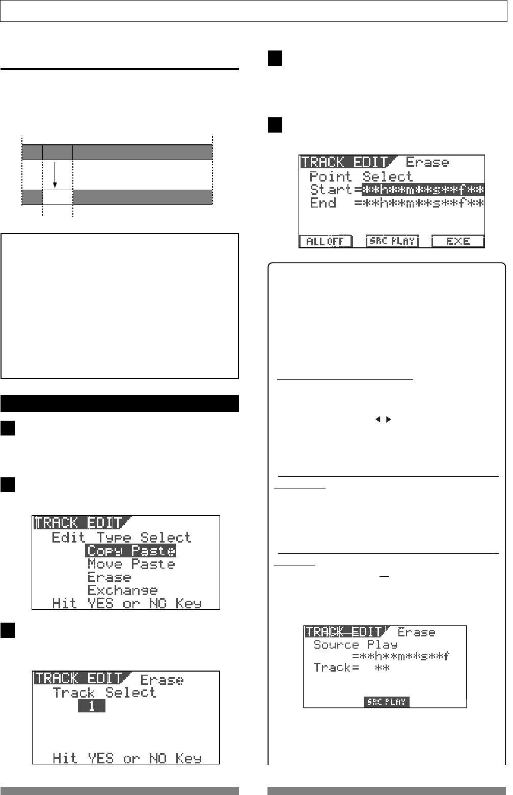
66
Recorder Functions
4
5
3
1
2
Erasing track data
You can erase a desired part of track data. You can
select a track or tracks (of which you are going to erase
data) from among each individual track, each pair of
tracks, 1-6 and 1-8.
START Point END Point
ABS 0 REC END
Erase
<Notes for the erase function>
• When all eight tracks (1 through 8) are recorded, if you
erase a part of the chosen track, only the erased part
becomes silent (no audio) and the following material
does not move advance to fill the gap.
Therefore, the REC END point remains the same.
However, if you erase a part between the chosen point
(=Start point) and the REC END point (=End point) of
all tracks, the REC END point moves advance.
• The erase operations are performed on the current
program. Therefore, do not change the current pro
gram until all the operations are completed.
Erasing
Set the Start and End points for the erase operation.
Using the digital scrub function, set the Start and End
points. See "Storing the digital scrub point" for details
about how to set the points.
While the recorder is stopped, press the [TRACK EDIT]
key.
The screen for selecting the track edit type appears.
Use the [JOG] dial to select "Erase" and then press the
[ENTER/YES] key.
The display shows the screen for selecting the track(s)
to be erased.
Use the [JOG] dial to select the track(s) to be erased.
Rotating the [JOG] dial changes the options among 1
through 8, 1&2, 3&4, 5&6, 7&8, 1-6, and 1-8.
The corresponding [TRACK STATUS/TRACK SEL] key(s)
of the selected track(s) light in red.
Press the [ENTER/YES] key after selecting the track(s).
The screen shows the Start and End points.
<Hint>
On the screen above, you can perform the following
operations.
1. Editing the Start and End points
2. Setting the Start point to "ABS 0" and the End point to "REC
END"
3. Checking the data to be erased
4. Setting the Start and End points by marks
• To edit the Start and End points:
Highlight the time field of a desired (Start or End) point, and
then press the [ENTER/YES] key.
The "seconds" value starts flashing, showing that you can
edit it. Use the [CURSOR / ] keys to move the flashing
value, and use the [JOG] dial to enter a value.
After entering the desired time, pressing the [ENTER/YES]
key to store the time data to the point.
• To set the Start point to "ABS 0" and the End point to
"REC END":
Press the [SETUP/F1] key while holding down the [SHIFT] key.
"ALL OFF" changes to "ALL ON", and the Start point is set
to "ABS 0", while the End point is set to "REC END" point.
This function is useful when you erase all track data.
• To check (monitor) the data to be erased [Source Play
function]:
Press the [TIME BASE SEL/F2] key while holding down the
[SHIFT] key.
The display shows the "Source Play" screen as shown
below and the recorder starts playback of the data to be
erased.
You can hear audio by moving up the corresponding
track fader. After checking audio, press the [STOP] key.
The display returns to the screen shown before perform-
ing the Source play function.
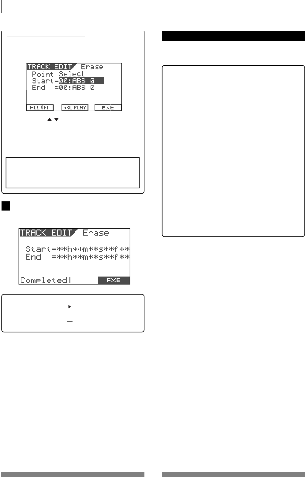
67
Recorder Functions
6
• To set editing points by marks:
Press the [TIME BASE SEL] key.
Each data field for the Start and End points changes to
show the current option by mark as shown below.
Use the [CURSOR / ] keys to highlight the field for the
desired point, and press the [ENTER/YES] key.
The field starts flashing.
Use the [JOG] dial to select the desired mark and press
the [ENTER/YES] key.
The editing point is set to the selected mark.
<Note>
This operation can be performed only when any mark
is set. When no mark is set, "
00:ABS 0
" is the one and
only option for each point.
Press the [UNDO/REDO/F3] key while holding down the
[SHIFT] key.
The erase function is performed. When finished, "Com-
pleted!" appears on the screen.
<Hint>
You may use the [CURSOR ] to highlight "EXE" and press
the [ENTER/YES] key to perform the function, instead of
pressing the [UNDO/REDO/F3] key while holding down the
[SHIFT] key.
• By pressing the [UNDO/REDO] key after completing
the erase operation, you can return the track(s) to the
condition before performing the erase operation.
• By pressing the [UNDO/REDO] key just after
performing the undo operation, you can undo the
undo operation and return the track(s) to the
condition after performing the erase operation.
Note the following for performing the undo/redo op-
eration.
<Notes>
You can undo or redo only when the recorder is stopped.
If you carry out any of the following after performing
the erase operation, you cannot undo/redo the erase
operation.
1.Making a new recording
2.Performing a new editing
3.Letting the recorder run in playback (or recording)
mode and pass through the auto punch-in point while
the auto punch mode is active
4.Turning off the power of the VF80
5.Performing any of the program operations (select,
rename or delete).
Undo/redo of Erase
You can undo an erase operation, as well as redo it
(undo the undo operation).
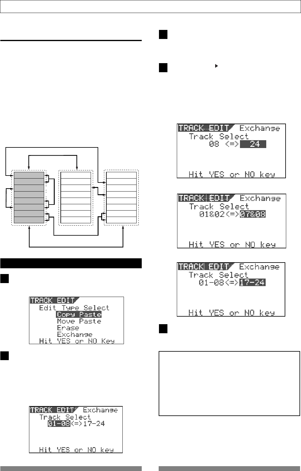
68
Recorder Functions
<Example 1> Exchanging Track 8 and Track 24
<Example 2> Exchanging Tracks 1&2 and Tracks 7&8
<Example 3> Exchanging Tracks 1-8 and Tracks 17-24
Track 1
Track 2
Track 3
Track 4
Track 5
Track 6
Track 7
Track 8
Track 9
Track 10
Track 11
Track 12
Track 13
Track 14
Track 15
Track 16
Track 17
Track 18
Track 19
Track 20
Track 21
Track 22
Track 23
Track 24
5
3
4
1
2
Track Exchange
The track exchange function allows you to exchange
tracks (regardless of whether they are real or addi-
tional tracks) on the program in single track unit, 2-
track unit or 8-track unit.
By using this function, you can exchange tracks not
only among real tracks but also between real and
additional tracks, allowing to use tracks effectively.
For example, by exchanging a recorded real track with
an empty additional track, you can transfer data on
a real track to an additional track temporarily, so that
you can record a new material onto the real track.
The track exchange function is also used to check the
REC END point on an additional track.
Performing the track exchange
While the recorder is stopped, press the [TRACK EDIT]
key.
The screen for selecting the track edit type appears.
Use the [JOG] dial to select "Exchange" and then press
the [ENTER/YES] key.
The display shows the screen for selecting the tracks to
be exchanged. The screen example below shows that
tracks 01 through 08 and tracks 17 through 24 are ex-
changed in 8-track unit.
The left field shows the source track(s), while the right
fields shows the destination track(s).
Use the [JOG] dial to select the source track(s).
Rotating the [JOG] dial changes the options among
single tracks (1 through 24), pair tracks (1&2 through
23&24), 1-8, 9-16 and 17-24.
Use the [CURSOR ] key to highlight (and flashes) the
right field, and use the [JOG] dial to select the destina-
tion track(s).
You can only select the same number of tracks as the
source track(s) selected in step 3 above.
For example, if you select a single track in step 3 above,
you can only select a single track here.
<Note for Track Exchange>
If the selected tracks for the left and right fields are re-
versed, the same track exchange is performed.
For example, "
1-8<->17-24
" and "
17-24<->1-8
" perform the
same track exchange.
The setting in which the same track(s) are selected for
both the left and right fields, such as "
1-8<->1-8
", is invalid.
If you press the
[ENTER/YES]
key with such a setting, the
display shows the message "
Select Err! Hit Any Keys
".
After selecting tracks, press the [ENTER/YES] key.
The track exchange function is performed and the dis-
play returns to the Normal screen.
One track exchange
8 track block exchange
8 track block exchange
2 track block exchange
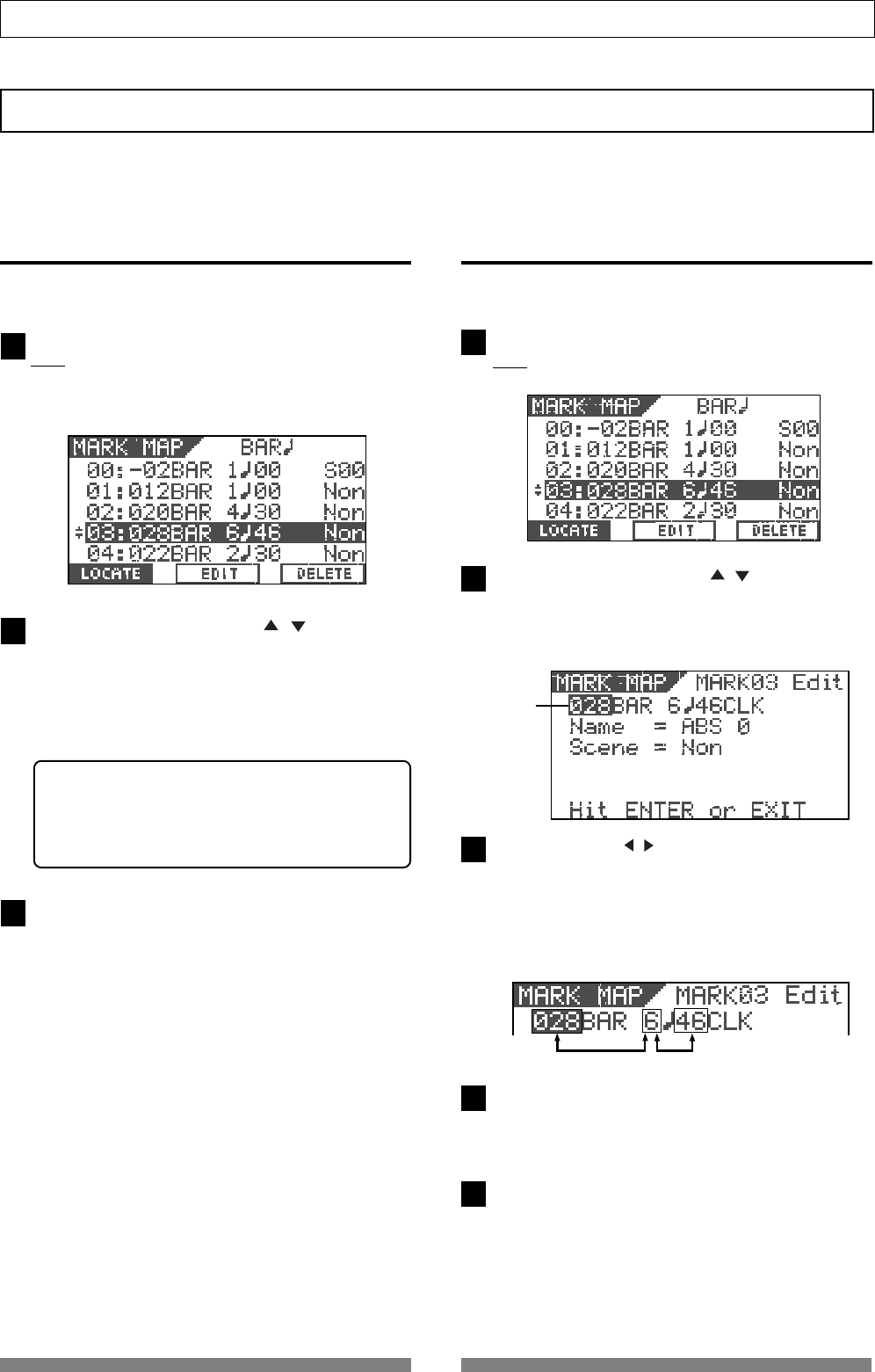
69
Recorder Functions
1
2
3
4
5
1
2
3
Blinking
Editing Marks
This section describes how to edit marks, assuming that more than one mark is already stored in realtime
according to the operations described in "Basic Recording and Playback".
Viewing the mark list
You can view the marks stored.
While the recorder is stopped, press the [SCENE SEQ./
MAP] key while holding down the [SHIFT] key.
The mark positions are shown by time or bar/beat/clock
values depending on the time base (In the following
screen example, the time base is set to "Bar/Beat/Clk").
Use the [JOG] dial or [CURSOR / ] keys to scroll
the marks stored.
In the Mark map screen, you can not only view all the
marks but also perform various operations (such as
editing a mark position, entering a mark title, locating
a mark, deleting a mark and adding a mark) described
later.
<Hint>
When the Mark map screen is shown, you can switch
the screen to display the position (by time or bar/
beat/clock) or title of each mark by pressing the
[TIME BASE SEL] key.
After viewing the list, press the [EXIT/NO] key.
The display returns to the Normal screen.
Editing a mark position
You can edit the current position of a mark in the
mark map.
While the recorder is stopped, press the [SCENE SEQ./
MAP] key while holding down the [SHIFT] key.
The Mark map screen appears.
Use the [JOG] dial or [CURSOR / ] keys to highlight
the desired mark, and then press the [TIME BASE SEL/
F2] key.
The display shows the screen for editing the chosen
mark.
Use the [CURSOR / ] keys to highlight (and flashes)
the field you want to edit, and then use the [JOG] dial
to select the desired value.
When the time base is set to "ABS" or "MTC", you can
edit fields for minute, second, frame and subframe.
When the time base is set to "Bar/Beat/Clk", you can
edit fields for bar, beat and clock, as shown below.]
After editing time (or bar/beat/clock), press the [ENTER/
YES] key.
The edited value is stored to the mark and the display
returns to the Mark map screen.
Press the [EXIT/NO] key.
The display returns to the Normal screen.
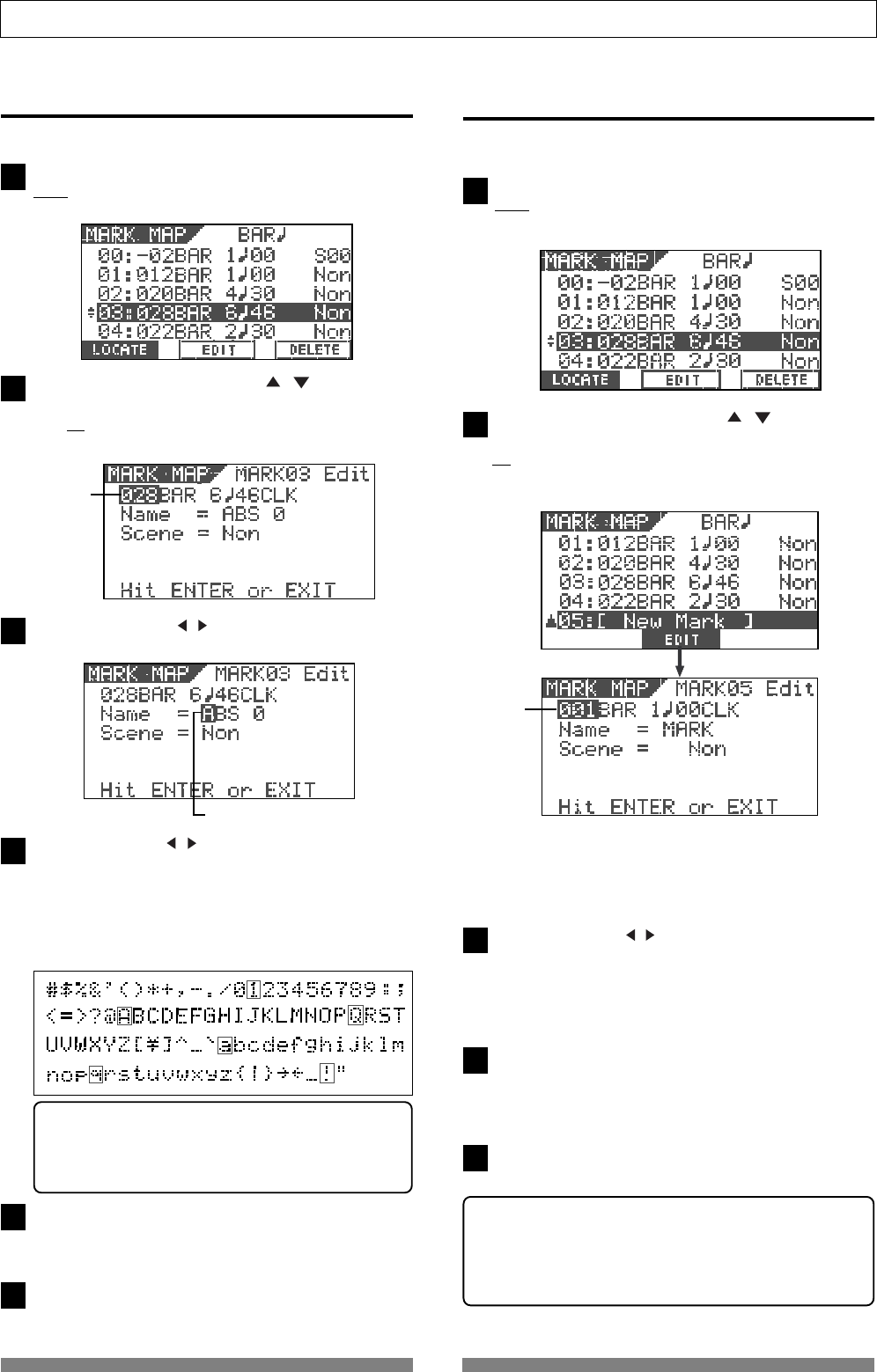
70
Recorder Functions
1
2
3
4
5
6
Highlight (and flashes) this point.
1
2
3
4
5
Enter a mark title
You can enter or edit a title for each mark.
While the recorder is stopped, press the [SCENE SEQ./
MAP] key while holding down the [SHIFT] key.
The Mark map screen appears.
Use the [JOG] dial or [CURSOR / ] keys to high-
light the desired mark, and then press the [TIME BASE
SEL/F2] key.
The display shows the screen for editing the chosen
mark.
Flashing
Press the [CURSOR / ] keys repeatedly to highlight
(and flashes) the leftmost point of the title field.
Use the [CURSOR / ] keys to move the highlighted
point among the title field, and use the [JOG] dial to
select the desired character.
You can use up to 14 characters for each title but be-
cause of the screen size, characters displayed at once
are limited. You can select a character from among the
following.
After entering/editing the title, press the [ENTER/YES]
key.
The entered/edited title is stored to the mark.
Press the [EXIT/NO] key.
The display returns to the Normal screen.
Hint
When selecting a character, rotating the [JOG] dial
while holding down the [SHIFT] key jumps among
characters surrounded with the box above.
Adding a mark
You can add a mark to the mark map.
While the recorder is stopped, press the [SCENE SEQ./
MAP] key while holding down the [SHIFT] key.
The Mark map screen appears.
Use the [JOG] dial or [CURSOR / ] keys to high-
light "New Mark", and then press the [TIME BASE SEL/
F2] key.
You can find "[New Mark]" at the bottom of the mark map.
Flashing
On the screen for editing the mark, "001" (Bar number
field) is flashing, showing that it can be edited.
The mark name is tentatively set to "Mark", while no
scene is assigned (indicated by "Non").
Use the [CURSOR / ] keys to highlight (and flashes)
the field you want to edit among BAR, BEAT and CLK,
and then use the [JOG] dial to select the desired value.
When setting the time base to ABS or MTC, you can set
the position in the similar way.
After setting the mark position, press the [ENTER/YES]
key.
The new mark is added to the mark map and the dis-
play returns to the Mark map screen.
Press the [EXIT/NO] key.
The display returns to the Normal screen.
<Hint>
When adding a new mark, you can also enter a mark title
or assign a scene for the scene sequence function.
See "Enter a mark title" above and "Scene Memory" in "Mixer
Functions" for details about operations.
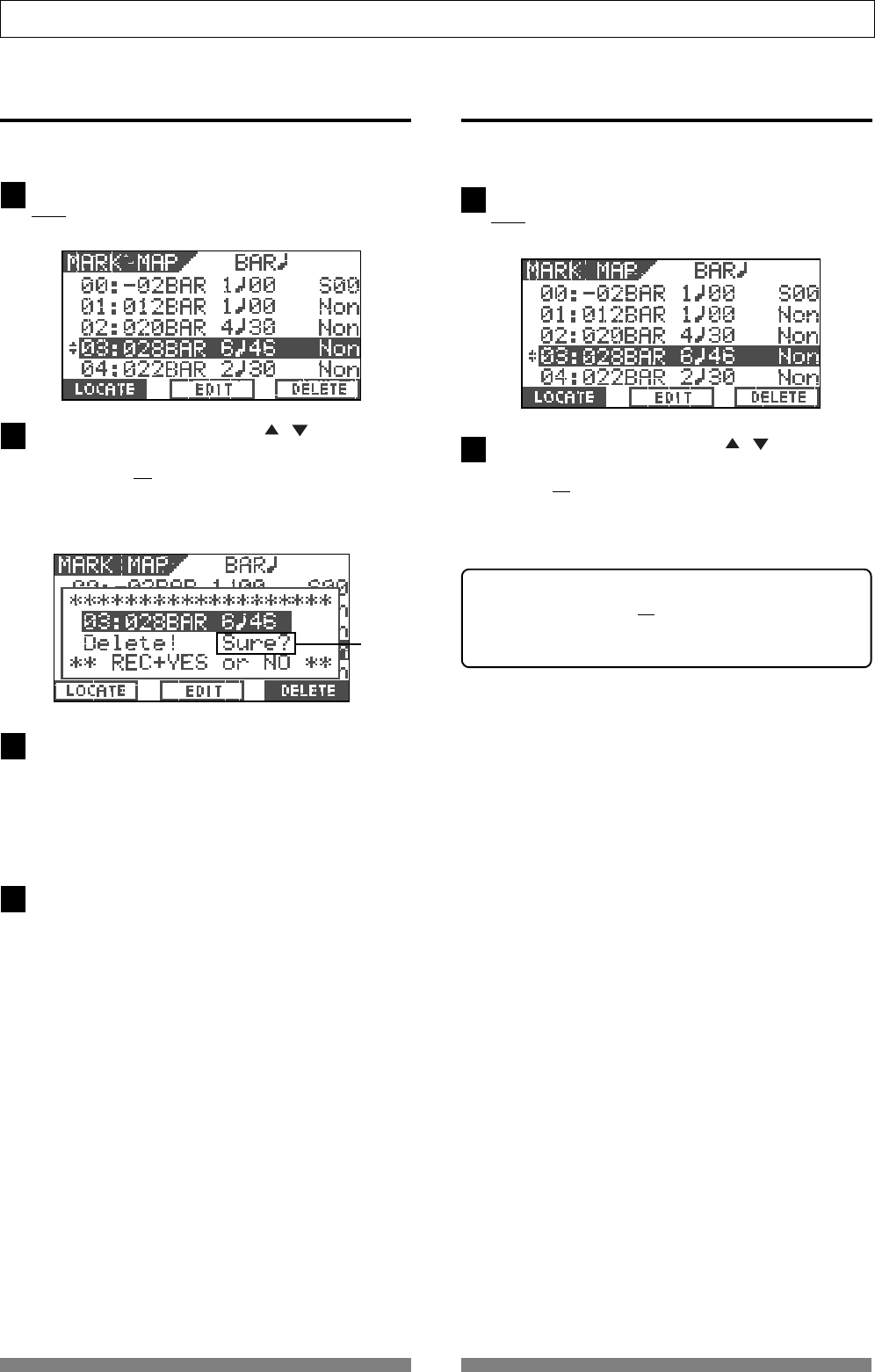
71
Recorder Functions
1
2
3
4
1
2
Flashing
Deleting a mark
You can delete an unnecessary mark.
While the recorder is stopped, press the [SCENE SEQ./
MAP] key while holding down the [SHIFT] key.
The Mark map screen appears.
Use the [JOG] dial or [CURSOR / ] keys to high-
light the mark you want to delete, and then press the
[UNDO/REDO/F3] key while holding down the [SHIFT]
key.
"Delete!" is shown and "Sure?" flashes.
To cancel the delete operation, press the [EXIT/NO] key.
Press the [ENTER/YES] key while holding down the
[RECORD] key.
The chosen mark is deleted and the mark map is sorted,
resulting marks following the deleted mark in the mark
map list move up.
For example, if you delete Mark 03, the current Mark
04, 05,... will replace Mark 03, 04,.... respectively.
Press the [EXIT/NO] key.
The display returns to the Normal screen.
Locating a mark
You can directly locate a mark.
While the recorder is stopped, press the [SCENE SEQ./
MAP] key while holding down the [SHIFT] key.
The Mark map screen appears.
Use the [JOG] dial or [CURSOR / ] keys to high-
light the mark you want to locate, and then press the
[SETUP/F1] key while holding down the [SHIFT] key.
The recorder locates to the selected mark, and the dis-
play returns to the Normal screen.
<Hint>
If you press the [SETUP/F1] key while holding down the
[SHIFT] key after editing a mark position (see "Editing a
mark position"), you can locate the new mark position.

72
Advanced Operations
1
2
3
4
5
1
2
3
1
1
Advanced Operations
This chapter describes advanced or useful functions of the VF80.
Metronome function
The VF80 provides the internal tempo map, in which you can set the time signature (e.g. 4/4, 3/4) and tempo
(between 30 and 250).
It also can output the metronome sound (click) according to the tempo map, allowing you to record materials
at the specific tempo without the need of an external metronome or rhythm machine.
The metronome sound can be output from Track 6 of the VF80 when you set "Click?" in the Setup menu to "On."
<Note>
When Track 6 is set to output the metronome sound (i.e. when you set "
Click?
" menu in the Setup menu to "
On
"),
you cannot record audio on Track 6 or playback audio recorded on Track 6.
When you have finished using the metronome function, we recommend setting "Click?" menu in the Setup mode
to "
Off
" so that you can use Track 6 for recording and playback.
Setting the tempo map
To output the metronome sound (click), the tempo
map must be set.
To set the tempo map, use "Signature Set" and "Tempo
Set" menus in the Setup mode.
Initially, the time signature is set to "4/4" while the
tempo is set to "120."
To change the initial settings, operate the following.
While the VF80 is stopped, press the [SETUP] key to
enter the Setup mode.
The screen for selecting a menu in the Setup mode ap-
pears.
Use the [JOG] dial to select the "Signature Set" menu,
and then press the [ENTER/YES] key.
The screen for setting the time signature appears.
Set the desired time signature according to the proce-
dure described in "Setting the time signature" on page 122.
After setting the time signature, press the [EXIT/NO]
key to return to the screen for selecting a menu in the
Setup mode.
Use the [JOG] dial to select the "Tempo Set" menu, and
then press the [ENTER/YES] key.
The screen for setting the tempo appears.
Set the desired tempo according to the procedure de-
scribed in "Setting the tempo" on page 124.
After setting the tempo, press the [EXIT/NO] key to
return to the screen for selecting a menu in the Setup
mode.
Go on to set the metronome output described below.
Setting the metronome output
You can set whether outputting the metronome sound
or not by "Click?" menu in the Setup mode.
Use the [JOG] dial to select the "Click?" menu, and then
press the [ENTER/YES] key.
The initial setting is "Off."
Use the [JOG] dial to select "On", and then press the
[ENTER/YES] key.
Now the metronome sound will be output from Track
6.
Press the [EXIT/NO] key repeatedly until exiting the
Setup mode.
Setting the time base to bar/beat
Press the [TIME BASE SEL] key to set the time base to
"Bar/Beat."
When the time base is set to "Bar/Beat", you can moni-
tor the current position by Bar/Beat according to the
tempo map you set.
Monitoring the metronome sound
Press the [PLAY] key to start playback of the VF80.
The level meter for Track 6 shows the metronome sound
level.
Set the Master and Track 6 faders to the "0" position,
and raise the [PHONES] knob to monitor the metronome
sound via the headphones.
You can now record a material while listening to the
metronome sound as a guide.
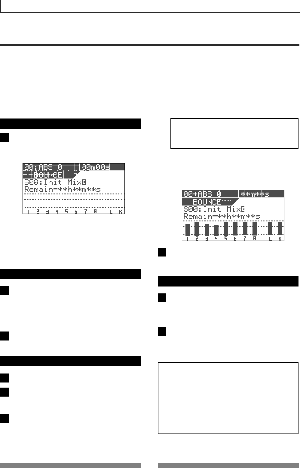
73
Advanced Operations
1
1
2
1
2
3
4
1
2
Track bounce (Ping-pong recording)
When the number of empty tracks is short in the recording process, you can solve the problem by transferring
audio on the multiple already-recorded tracks to a different track or tracks.
This operation is called "Track bounce" or "Ping-pong recording". With the VF80, you can do this operation simply
by using the [BOUNCE] key.
When the Bounce mode is active, Tracks 7/8 are automatically armed and the materials recorded on Tracks 1
through 6 are ready to be bounced to Tracks 7/8.
In the following description for track bouncing operation, we assume that mono materials are recorded on Tracks
1 through 4, while a stereo material is recorded on Tracks 5 and 6.
On/off of bounce mode
Press the [BOUNCE] key.
Each press of the key alternates "On" and "Off."
When set to "On", the key is illuminated, while the
Bounce screen appears where "Remain" is displayed.
Tracks 7/8 are automatically armed and the corre-
sponding [TRACK STATUS/TRACK SEL] key flashes in red.
When the Bounce mode is active, you cannot arm the
other tracks (1 through 6).
Setting pan positions
Press the [PAN] key to set the pan position for each
track.
Set the pan positions at the desired points for Tracks 1
through 4, fully left for Track 5 and fully right for Track
6. See "Mixer Functions" for details about the pan set-
ting.
After setting all pan positions, press the [EXIT/NO] key.
The balance mode screen appears.
Setting level of each track
Set the [MASTER] fader to the "0" position.
Press the [RECORD] key only.
The [RECORD] key starts flashing, while Tracks 7/8 enter
the input monitor mode.
Press the [PLAY] key to start playback and adjust play-
back levels of Tracks 1 through 6 using the track fad-
ers.
Be careful not to light up the peak indicator when ad-
justing the playback level of each track.
<Note>
If the peak indicator lights up, the recorded sound
will be distorted. Adjust the playback level of each
track appropriately.
You can see the playback levels on Tracks 1 through 6,
input levels on Track 7/8 and output levels of the Ste-
reo busses (L and R) via the meters on the screen.
By raising the [PHONES] knob, you can monitor the
sound.
After adjusting the levels, stop the recorder and then
locate the beginning position of track bouncing.
Performing the track bounce
Press the [PLAY] key while holding down the
[RECORD] key to start track bouncing.
The recorder starts recording of mixed audio from
Tracks 1 through 6 to Tracks 7/8.
After finishing the track bounce, press the [STOP] key
to stop the recorder.
Now you can use Tracks 1 through 6 to record new
materials.
<Notes>
• You can also apply EQ and/or effects to audio signals
on Tracks 1 through 6 to be bounce to Track 7/8.
See "
Mixer Function
" for details about how to apply EQ
and effects.
• When the Bounce mode is active, you can use any of
effect types
L01
through
L38
. Note that, if you enter
the Bounce mode when any of insert effect types is
selected, “
L01: Norm HALL
” will be automatically
selected.
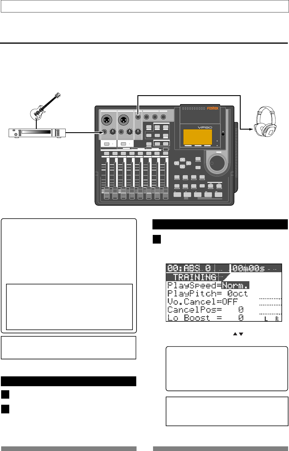
74
Advanced Operations
2
DIGITAL MULTITRACKER
LOCATE ABS 0
LOCATE REC END
SEL
TIMEBASE
CURSOR
PHANTOM
ACCESS
PEAK
CH ON/OFF
LR
GUITAR
GUITAR
LINE MIC LINE MIC MIN MAX
MASTERING TRAINING
EFFECTEQPAN
SCENE SEQ.SCENE
TRACK
UNDO
SETUP
PUNCH
AUTO LOOP PITCH SCRUB
VARI
F FWDREWINDPLAYSTOPRECORD
EXIT
ENTER
TRIMTRIM
WAVE FORM
MIX PARAMETER
PGM FADER MAP
ON/OFF
2TRK MODE
F1 F2 F3 SHIFT
EDIT EDIT EDIT MARK DELETE
LOCATE
FOOT SW
ST OUT
PHONES
INPUT A
BOUNCE
INPUT B
+6
-10
-20
-40
-
∞
-30
0
+6
-10
-20
-40
-
∞
-30
0
+6
-10
-20
-40
-
∞
-30
0
+6
-10
-20
-40
-
∞
-30
0
+6
-10
-20
-40
-
∞
-30
0
+6
-10
-20
-40
-
∞
-30
0
+6
-10
-20
-40
-
∞
-30
0
+6
-10
-20
-40
-
∞
-30
0
PEAK
CH ON/OFF
2345 6 7/8 2TRK1 MASTER
TRACK STATUS / TRACK SEL
TRACK STATUS
RED REC GREEN PLAY OFF MUTE STATUS
/SEL
EJECT
/YES
/NO
SHUTTLE
JOG
UNBAL UNBAL
BAL
BAL
F1 F2 F3
EDIT
/REDO
REC EFF
1
1
Training mode
The VF80 provides the training mode which allows you to practice your instrument while playing back only Tracks
7/8. In the training mode, you can slow down the playback speed or altering the pitch, making it easy to play
along with your favorite musicians or transcribing ad-lib phrases.
You can also cancel the vocal or lead guitar solo which is positioned in the center, allowing you to replace it with
your vocal or guitar (like a karaoke).
The following description shows how to play the guitar along with audio recorded on Tracks 7/8.
<Hint>
Because only Tracks 7/8 can be played back in the Train-
ing mode, you have to record a song used for your prac-
tice in advance.
If you are going to use a song recorded on other tracks,
it will be a good idea to use the track exchange function
to move the song to Tracks 7/8.
Also, when you want to use an external source on CD,
MD, etc., record it onto Tracks 7/8 digitally using the
technique described later in "Digital Recording."
<Caution>
When copying a copyright material from CD, MD, etc.,
do not use the copy for any purpose except your prac-
tice or enjoyment. Any unauthorized use of the copy
for commercial purpose will constitute infringement
of such copyright and will render the infringer liable
to an action at law.
<Note>
When the training mode is active, you cannot make any
recording, as well as playback
Tracks 1 through 6
.
Connecting the instrument and headphones
Set the [MASTER] fader to the "∞" position.
Connect the instrument and headphones as shown in
the illustration above.
You may connect the instrument either [INPUT A] or
[INPUT B].
On/Off of training mode
Press the [TRAINING] key.
Each press of the key alternates "On" and "Off."
When set to "On", the [TRAINING] key is illuminated,
while the display shows the training mode screen.
On the training mode screen, you can set the follow-
ing. You can use the [CURSOR / ] key to select (high-
light) the item to be set.
1. Playback speed
2. Playback pitch
3. On/Off of the center cancel function
4. Setting of the cancel position
5. Low boost setting (for emphasizing the bass
sound)
<Note>
You can set the playback speed only while the VF80
is stopped. The other items can be set both while
stopped and during playback.
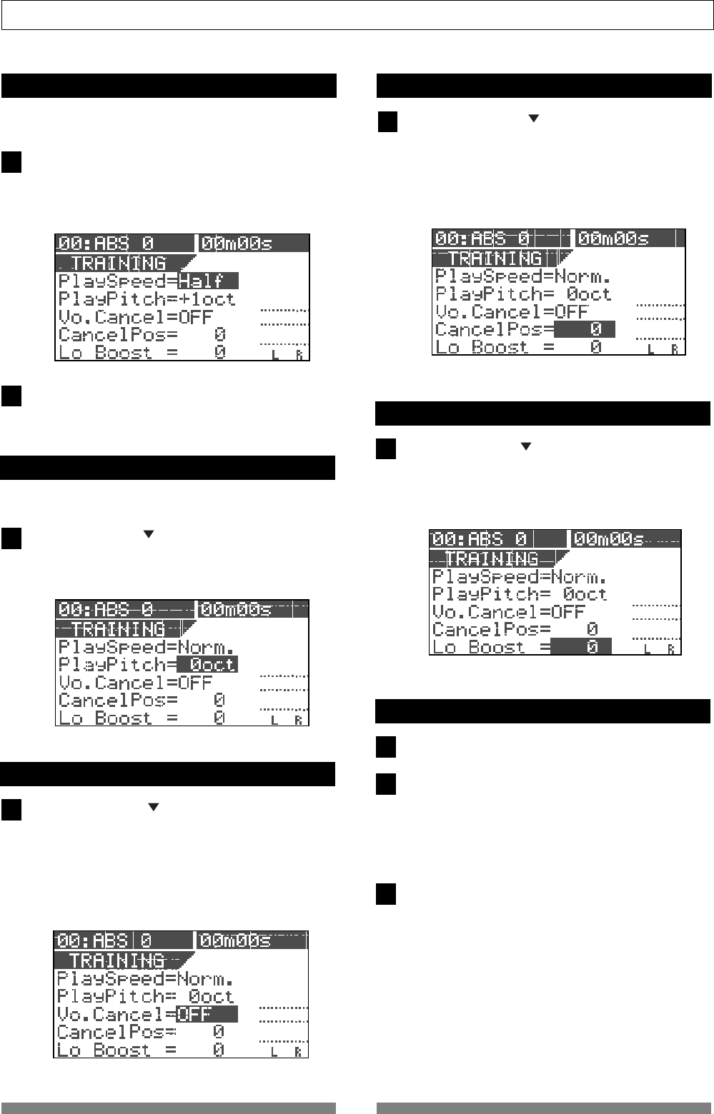
75
Advanced Operations
1
1
1
1
1
2
1
2
3
Slowing down the playback speed
You can change the playback speed only while the
recorder is stopped.
When "Norm" in the "Play Speed" field is highlighted,
use the [JOG] dial to select "Half."
The playback speed is set to half the normal speed and
the pitch automatically raises one octave.
To change only the pitch, see the next section.
To return to the normal speed, use the [JOG] dial to
select "Norm."
The playback speed returns to the normal speed.
Changing the pitch
The following items can be set both while stopped and
during playback.
Using the [CURSOR ] key to highlight the "Play Pitch"
field, and then use the [JOG] dial to select the desired
pitch.
You can set the pitch within the range of +/- one octave.
Canceling the center-positioned sound
Using the [CURSOR ] key to highlight the "Vo. Can-
cel" field, and then use the [JOG] dial to select "ON".
You can cancel the center-positioned sound such as a
lead vocal.
Depending on audio sources, you may not perfectly
cancel the sound you want to remove because it is not
exactly center-positioned. In such a case, perform the
next operation.
Setting the cancel position
Using the [CURSOR ] key to highlight the "Cancel
Pos" field, and then use the [JOG] dial to set the de-
sired value.
You can select the cancel position from "-99" via "0" to
"+99" in one step increments.
Try to find the best position where the sound to be
cancel gets lowest.
Boosting the bass sound
Using the [CURSOR ] key to highlight the "Lo Boost"
field, and then use the [JOG] dial to set the desired
value.
You can select the low boost level from "0" to "10" in one
step increments.
Playing along with the playback sound
Set the [MASTER] fader to the "0" position.
Press the [PLAY] key to starts playback of the VF80 and
raise the Track 7/8 fader gradually.
You can see the level is going up via the stereo output
level meters (L and R) on the screen.
Rotate the [PHONES] knob to adjust the headphones
level.
Play the guitar along with the playback sound of Tracks
7/8, while adjusting the [TRIM] knob to the appropri-
ate position where the [PEAK] indicator for the input
you connect the guitar does not light.
You can hear both the playback sound of Tracks 7/8
and your guitar together from the headphones.
If you move down the Tracks 7/8 fader, you can only
hear your guitar.
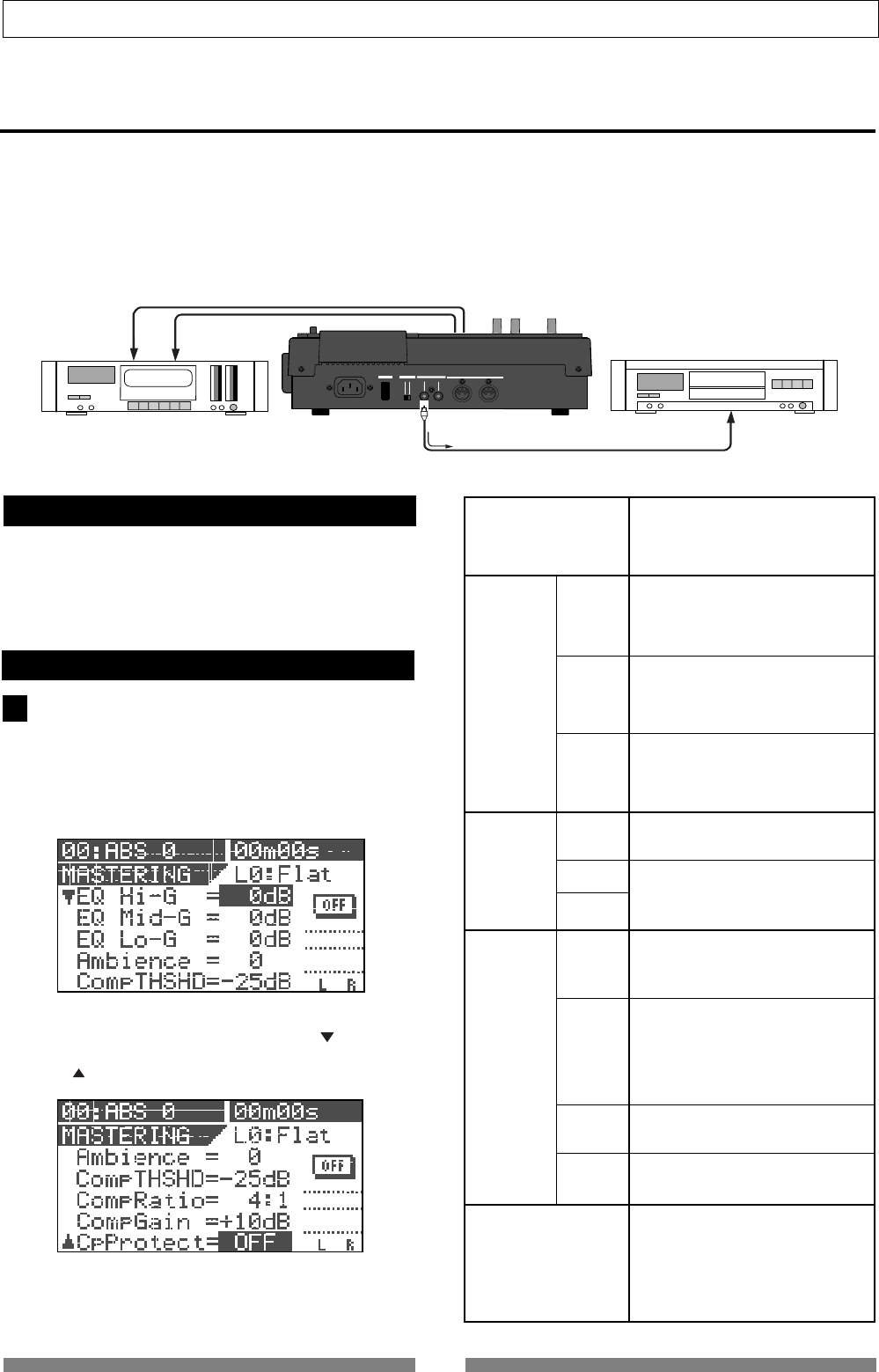
76
Advanced Operations
OFF
ON
MIDI
OUTPUT INPUT OUTPUT
INPUT
POWER PHANTOM S/P DIF / DATA
STEREO OUT L, R
S/P DIF OUTPUT
Digital master recorder
Analog master recorder
1
Mastering library
EQ
Ambience
Compressor
High Gain
Mid Gain
Low Gain
Rev Level
Rev Time
Pre Delay
Threshold
Ratio
Gain
Atack
Copy Protect
Mastering mode
You can use Tracks 7/8 as the mastering tracks.
After performing the track bouncing to mix down track signals to Tracks 7/8, you can record the audio signals
on Tracks 7/8 to an external (analog or digital) master recorder with applying EQ, reverb and compressor for
mastering (see the illustration below).
You can perform the above operation in the mastering mode, which can be selected by the [MASTERING] key.
When the mastering mode is active, only Tracks 7/8 can be played back, while the dedicated sound processing
for mastering is available. In the following description, we assume that the stereo mix signals are recorded on
Tracks 7/8.
Selecting a program to be played back
If there is more than one program in the VF80, select
the desired program to be played back.
See "Selecting a program" for the operation.
On/off of mastering mode
Press the [MASTERING] key.
Each press of the [MASTERING] key alternates ON and
OFF of the mastering mode.
When setting to ON, the [MASTERING] key is illuminated
and the following screen is displayed, while the [TRACK
STATUS/TRACK SEL] key of Track 7/8 and the [STATUS/
SEL] key for the master are illuminated in green.
The screen example above shows the upper part of the
mastering setting. Pressing the [CURSOR ] key scrolls
down the setting items. To scroll up, press the [CUR-
SOR ] key.
The table below shows the mastering setting items.
You can select a desired preset entry
from 10 entries stored in the effect library.
See "Mastering library details" on the
next page.
Adjusts the EQ gain for the high fre-
quency range within a +/- 18 dB range.
Freq. and Q: fixed
Adjusts the EQ gain for the middle fre-
quency range within a +/- 18 dB range.
Freq. and Q: fixed
Adjusts the EQ gain for the low fre-
quency range within a +/- 18 dB range.
Freq. and Q: fixed
Adjusts the amount of reverb sound be-
tween 0 and 99.
Fixed (See “Mastering library details” on
the next page.
Fixed (See “Mastering library details” on
the next page.
Adjusts the threshold of the compres-
sor between -50 dB and 0 dB in 1 dB
steps.
Selects the compressor ratio from the
following options.
∞:1, 20:1, 10:1, 8:1, 6:1, 5:1, 4:1, 3.5:1,
3:1, 2.5:1, 2:1, 1,7:1, 1.5:1, 1.3:1, 1.1:1,
1:1
Adjusts the compressor gain between
0 dB and +18 dB.
Selects ON or OFF of the copy protec-
tion for the S/P DIF output signal.
When set to ON, the flag for limiting a
digital copy to one generation is set in
the S/P DIF digital output signal.
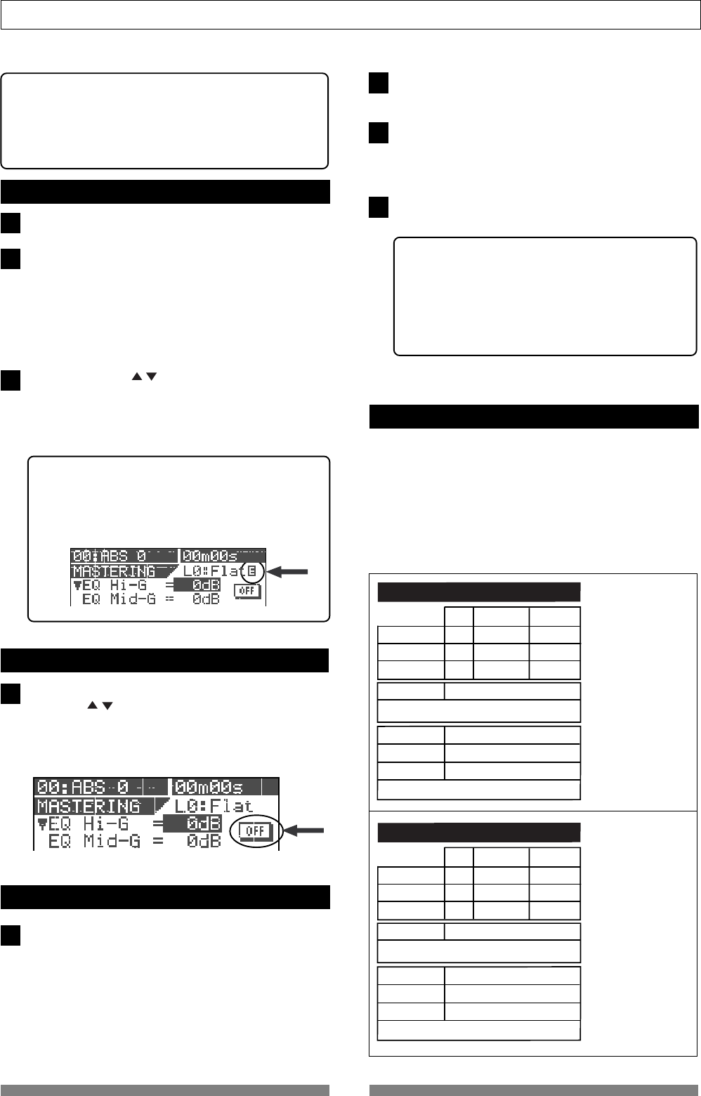
77
Advanced Operations
3
1
2
1
1
2
3
4
Gain Freq. (fixed) Q (fixed)
EQ Lo
EQ Mid
0
0
400Hz
1kHz
L-S
1
L0: FLAT
EQ Hi
0
4kHz H-S
Comp THSHD
Comp Ratio
Comp Gain
Ambience 0 (Rev Level)
+10
4 : 1
-25
Rev Time=1.0s / Pre Dly=0ms : fixed
Atack Time = 8ms : fixed
Gain Freq. (fixed) Q (fixed)
EQ Lo
EQ Mid
0
+4.0
400Hz
1kHz
L-S
1.0
L1: Wet Mix
EQ Hi
0
8kHz H-S
Comp THSHD
Comp Ratio
Comp Gain
Ambience 75 (Rev Level)
+10
3 : 1
-30
Rev Time=0.5s / Pre Dly=0ms : fixed
Atack Time = 5ms : fixed
<Hint>
When selecting a desired preset entry from the Master-
ing library, the initial parameter values of the entry are
shown on the screen.
See "Mastering library details" on the next page for the
detailed information.
Setting the mastering parameters
Set the [MASTER] fader at the "0" position.
Start playback and move up the Track 7/8 fader gradu-
ally.
You can monitor the playback sound of Tracks 7/8 by
rotating the [PHONES] knob clockwise.
In the mastering mode, you cannot monitor the play-
back sound of other tracks even if you move up the
faders.
Use the [CURSOR / ] key to highlight the parameter
value to be edited, and use the [JOG] dial to select the
desired value.
You can monitor the tailored sound of Tracks 7/8 in
realtime.
<Hint>
When any parameter value is changed from the
initial setting, "E" appears on the right of the preset
entry name (as shown below), showing that the cur-
rent setting is different from the initial setting.
On/off of the mastering processing
To switch on or off the mastering processing, use the
[CURSOR /] key to highlight the ON/OFF icon as
shown below, and use the [JOG] dial to select "ON" or
"OFF".
When "ON" is selected, the tailored sound is output.
When "OFF" is selected, the original sound is output.
Recording onto the master recorder
Stand by the master recorder for recording, and start
playback of the VF80.
You have to adjust the recording level now.
When the recording signal is digitally transferred from
the VF80 to the recorder, because a digital recorder usu-
ally does not provide the function for controlling the
digital input level, you must adjust the recording level
by controlling the stereo output level of the VF80 us-
ing the [MASTER] fader.
After setting the recording level, return the VF80 to the
beginning of the program.
Start recording of the master recorder and then start
playback of the VF80.
The stereo output (L and R) signals are recorded onto
the master recorder.
After finishing recording, stop the both machines.
<Hint>
When you record VF80 audio onto a digital master
recorder via the S/P DIF digital signal, if the copy
protection ("Cp Protect") is set to "ON", you can limit
the digital copy from the master to another recorder.
If you do not want to make digital copies freely from
the master, set the copy protection to "ON."
Mastering library details
The mastering library provides 10 preset entries
which can only be used in the mastering mode.
When applying mastering processing to the sound,
you can use a desired preset as a starting point of your
setting.
The following table shows the initial settings of EQ,
reverb and compressor parameters, as well as the
major usage for each preset.
<Comment>
Basic mastering set-
tings.
Can be used for a wide
range of music genre.
<Comment>
Makes a dry sound
wet.
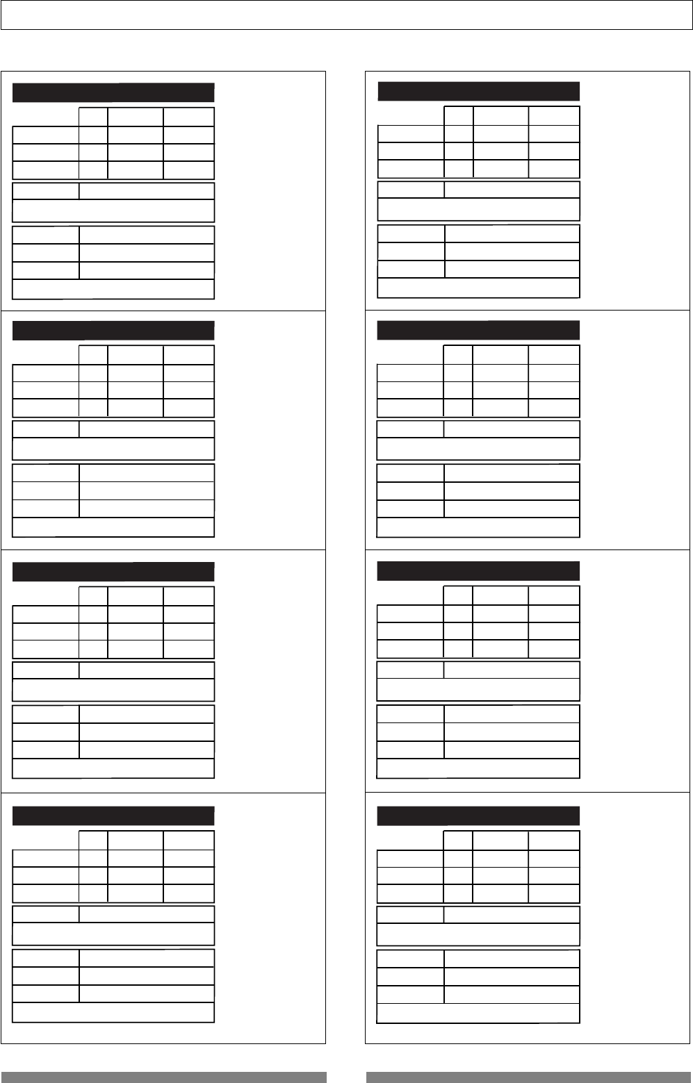
78
Advanced Operations
Gain Freq. (fixed) Q (fixed)
EQ Lo
EQ Mid
0
+4.0
400Hz
1kHz
L-S
1.0
L2: Light Mix
EQ Hi
0
8kHz H-S
Comp THSHD
Comp Ratio
Comp Gain
Ambience 0 (Rev Level)
+18
3 : 1
-42
Rev Time=1.0s / Pre Dly=0ms : fixed
Atack Time = 10ms : fixed
Gain Freq. (fixed) Q (fixed)
EQ Lo
EQ Mid
0
-18
400Hz
1kHz
L-S
1.0
L3: Live Mix
EQ Hi
0
8kHz H-S
Comp THSHD
Comp Ratio
Comp Gain
Ambience 99 (Rev Level)
+8
1.5 : 1
-20
Rev Time=0.1s / Pre Dly=30ms : fixed
Atack Time = 5ms : fixed
Gain Freq. (fixed) Q (fixed)
EQ Lo
EQ Mid
-3
+2
400Hz
500Hz
L-S
2.0
L4: Pop Mix
EQ Hi
-3
4kHz H-S
Comp THSHD
Comp Ratio
Comp Gain
Ambience 80 (Rev Level)
+18
3.5 : 1
-36
Rev Time=0.7s / Pre Dly=0ms : fixed
Atack Time = 10ms : fixed
Gain Freq. (fixed) Q (fixed)
EQ Lo
EQ Mid
+10
+15
400Hz
550Hz
L-S
3.5
L5: Dance
EQ Hi
-18
10kHz 3.5
Comp THSHD
Comp Ratio
Comp Gain
Ambience 0 (Rev Level)
+14
5 : 1
-30
Rev Time=1.0s / Pre Dly=0ms : fixed
Atack Time = 5ms : fixed
Gain Freq. (fixed) Q (fixed)
EQ Lo
EQ Mid
-18
LPF-ON
400Hz
2kHz
L-S
1
L9: LO_Fi
EQ Hi
+15
2kHz LPF
Comp THSHD
Comp Ratio
Comp Gain
Ambience 0 (Rev Level)
+5
∞ : 1
-25
Rev Time=1.0s / Pre Dly=0ms : fixed
Atack Time = 5ms : fixed
Gain Freq. (fixed) Q (fixed)
EQ Lo
EQ Mid
+4
-8
400Hz
500Hz
L-S
1
L8: Hall
EQ Hi
-4
6kHz H-S
Comp THSHD
Comp Ratio
Comp Gain
Ambience 80 (Rev Level)
+5
1.5 : 1
-25
Rev Time=3.0s / Pre Dly=100ms : fixed
Atack Time = 8ms : fixed
Gain Freq. (fixed) Q (fixed)
EQ Lo
EQ Mid
0
0
400Hz
1kHz
L-S
1
L6: Hard
EQ Hi
0
4kHz H-S
Comp THSHD
Comp Ratio
Comp Gain
Ambience 0 (Rev Level)
+18
8 : 1
-36
Rev Time=1.0s / Pre Dly=0ms : fixed
Atack Time = 5ms : fixed
Gain Freq. (fixed) Q (fixed)
EQ Lo
EQ Mid
-6
LPF-ON
400Hz
1kHz
L-S
1
L7: 70s
EQ Hi
0
6kHz LPF
Comp THSHD
Comp Ratio
Comp Gain
Ambience 0 (Rev Level)
+2
5 : 1
-10
Rev Time=1.0s / Pre Dly=0ms : fixed
Atack Time = 5ms : fixed
<Comment>
Makes a sound like
recorded in a small
live house.
<Comment>
Suitable for typical
pop music with vocal.
<Comment>
Suitable for a dancing
floor. A speedy sound
which makes an audi-
ence excite.
<Comment>
Powerful sound.
<Comment>
Soulful and energetic
sound of 70s'.
<Comment>
Makes a sound like
recorded in a concert
hall.
<Comment>
Narrow range sound
by limiting the fre-
quency range drasti-
cally.
<Comment>
Makes a dark sound
bright.
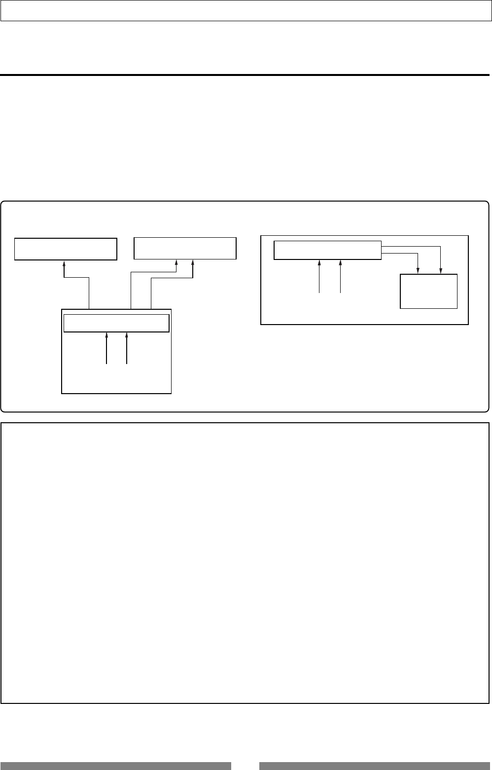
79
Advanced Operations
The internal mastering function is an expansion of the mastering function described earlier.
It allows you to record a mixed-down material on tracks 7 and 8 to the current drive on the VF80
while applying a mastering effect.
Therefore, unlike the mastering function, this function allows you to make high-quality mastering
inside the VF80, without the need of an external master recorder.
In addition, by installing the optional CD-RW drive (Model CD-1A), you can create original audio
CDs from the materials mixed down internally using the internal mastering function. See "Making an
Audio CD" on page 115 in "Save/load of song data" for details.
Internal Mastering Function
After executing internal mastering, a new program which saves a mastering material is automatically
created on the current drive, whose program number is set to one greater than the current greatest
program number.
For example, if there are 8 programs (P01 through 08) on the current drive, after mastering a desired
program data using the internal mastering function, a new program (P09) is automatically created and
the mastering signals produced by the mastering function are recorded on tracks 1 and 2 of P09.
Note that if the VF80 is under either of the following conditions, you cannot carry out internal mastering.
<Please read this first before carrying out operations in the internal mastering mode!>
<Conventional mastering mode> <Newly added internal mastering function>
The internal mastering function allows you
to carry out all operations using the VF80
only.
1. There are 99 programs already existed on the current drive even though there is enough
recording space.
If you try to carry out internal mastering, "Can't New PGM!" is shown and the operation is ignored.
To carry out internal mastering, delete an unnecessary program.
2. There is not enough remaining space even though there are less than 99 programs on the current
drive.
If you try to carry out internal mastering, "Over Time!" is shown and the operation is ignored.
To carry out internal mastering, erase unnecessary song data or delete an unnecessary program.
See "Deleting a program" on page 62 and "Erasing track data" on page 66 in this manual.
<Figure-1>
<Figure-2>
Mastering Effect
Tracks 7 & 8
Analog Master Recorder
Digital Master Recorder
VF80
ST OUT
S/P DIF OUT LR
Mastering Effect
Tracks 7 & 8
VF80
New Program
Tracks 1 & 2
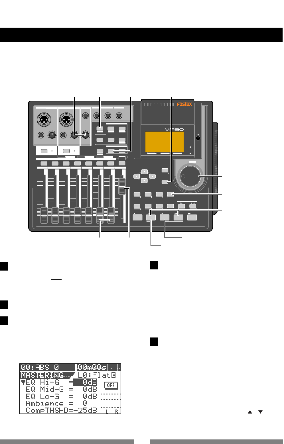
80
Advanced Operations
Select the desired program for mastering.
To select the desired program, while stopped, press
the [TRACK EDIT/PGM] key while holding down the
[SHIFT] key, and select the program using the [JOG]
dial, then press the [ENTER/YES] key.
Set the [MASTER] fader to the "0" position.
Press the [MASTERING] key.
The VF80 enters the mastering mode and the display
shows the mastering screen in which you can adjust
the mastering effects.
The [MASTERING] key lights up in red, while the [TRACK
STATUS/TRACK SEL] keys of tracks 7/8 and the master
channel light up in green.
Before performing the internal mastering, you can rehearse it as many times as you like, while
adjusting the track 7/8 level and sound effects.
In the following description, we assumes that a bounced material is recorded on tracks 7/8 of the
playback program. Headphones for monitoring are connected to the [PHONES] jack.
Rehearsing internal mastering
Press the [PLAY] key to start playback from the
beginning of the selected program.
The VF80 starts playback, while the display keeps
showing the screen for adjusting the mastering effects.
Tracks 1 and 2 are internally set to "input monitor",
allowing you to check over-level via the peak LED
indicators.
You can monitor the mastering sound through
headphones by raising the track 7/8 fader and/or
[PHONES] level control. The mastering levels are
shown on the level meters at the right on the screen.
During playback, adjust track 7/8 levels using
the 7/8 fader, as well as EQ and effect settings if
necessary.
Set the levels properly so that the PEAK LED indica-
tors do not flash or light frequently.
Note that levels may increase by changing EQ or
compressor parameters. When controlling the sound
characters and level, you should not only monitor the
level meters and listen to the sound, but also monitor
the PEAK LED indicators.
To adjusting the mastering effect parameters on the
mastering screen, use the [CURSOR] ( / ) keys to
select a parameter and the [JOG] dial to change the
parameter value.
<screen for adjusting the mastering effects>
DIGITAL MULTITRACKER
LOCATE ABS 0
LOCATE REC END
SEL
TIMEBASE
CURSOR
PHANTOM
ACCESS
PEAK
CH ON/OFF
LR
GUITAR
GUITAR
LINE MIC LINE MIC MIN MAX
MASTERING TRAINING
EFFECTEQPAN
SCENE SEQ.SCENE
TRACK
UNDO
SETUP
PUNCH
AUTO LOOP PITCH SCRUB
VARI
F FWDREWINDPLAYSTOPRECORD
EXIT
ENTER
TRIMTRIM
WAVE FORM
MIX PARAMETER
PGM FADER MAP
ON/OFF
2TRK MODE
F1 F2 F3 SHIFT
EDIT EDIT EDIT MARK DELETE
LOCATE
FOOT SW
ST OUT
PHONES
INPUT A
BOUNCE
INPUT B
+6
-10
-20
-40
-
∞
-30
0
+6
-10
-20
-40
-
∞
-30
0
+6
-10
-20
-40
-
∞
-30
0
+6
-10
-20
-40
-
∞
-30
0
+6
-10
-20
-40
-
∞
-30
0
+6
-10
-20
-40
-
∞
-30
0
+6
-10
-20
-40
-
∞
-30
0
+6
-10
-20
-40
-
∞
-30
0
PEAK
CH ON/OFF
2345 6 7/8 2TRK1 MASTER
TRACK STATUS / TRACK SEL
TRACK STATUS
RED REC GREEN PLAY OFF MUTE STATUS
/SEL
EJECT
/YES
/NO
SHUTTLE
JOG
UNBAL UNBAL
BAL
BAL
F1 F2 F3
EDIT
/REDO
REC EFF
[TRACK EDIT]
1
[MASTERING]
3
[ENTER/YES]
1
1
[JOG]
1
[SHIFT]
4
[PLAY]
5
[7/8 FADER]
2
[MASTER FADER]
[PHONES]
5
6
[STOP]
7
[STOP] + [REWIND]
1
2
3
4
5
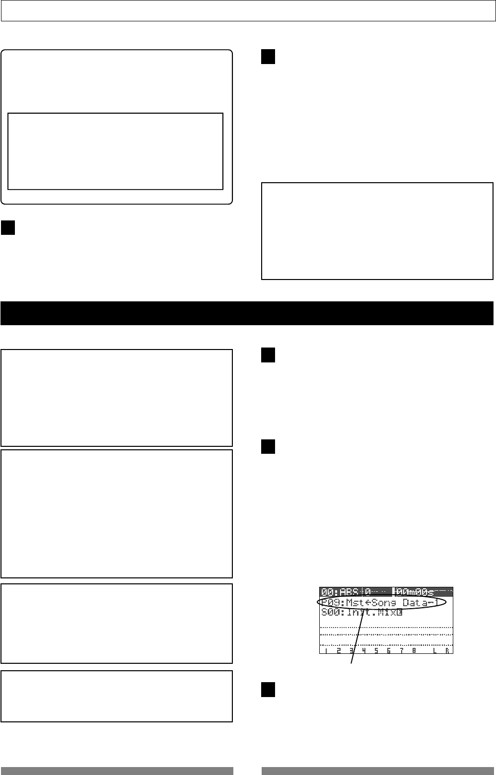
81
Advanced Operations
Performing internal mastering
<Hint>
On the mastering screen, you can tailor the sound
by adjusting EQ settings (HI, MID and LOW), as well
as the ambiance and compressor.
See page 76 for details about the mastering effects.
<Note>
In the internal mastering function, the
"CpProtect"
(Copy Protect) setting, which is one of the master-
ing effect items, does not affect the internally record
material. The copy protect setting affects materials
recorded on a CD-RW/CD-R disc, described later.
See "
Making an audio CD
" on page
115
.
Press the [REWIND] key while holding down the
[STOP] key to locate the beginning of the pro-
gram.
The VF80 locates the beginning of the program im-
mediately and "00m 00s" is shown at the top right of
the screen. Keep showing the same mastering screen
after stopping the VF80 and locating the beginning of
the program.
To repeat the rehearsal, perform steps 4 and 5 re-
peatedly after making the VF80 locate the beginning
of the program. After completing the rehearsal satis-
factorily, make sure to locate the beginning of the
program.
<Note: There is no need for selecting recording tracks.>
In the internal mastering function, unlike the normal
recording, you do not have to select recording tracks.
When recording a take in the internal mastering func-
tion according to the following procedure, the VF80 au-
tomatically arms Tracks 1 and 2.
Therefore, the
[TRACK STATUS/TRACK SEL]
keys for tracks
1 and 2 never light up in red during recording.
Please read the following notes carefully before performing internal mastering.
<Note: You cannot undo an internal mastering take.>
You cannot undo an internal mastering take.
If you are not satisfied with the result, try again from
the beginning.
If you do not need a previously recorded program, de-
lete the program according to the procedure described
in
"Deleting a Program"
of the owner's manual.
<Note>
Internal mastering cannot be performed if rec-protected.
If the
"Rec Protected"
setting of the setup mode is set to
"ON"
, you cannot perform internal mastering.
If you try to perform it, a warning message (
"Protected!"
)
appears on the display. If this message appears, set the
"Rec Protected"
setting to
"OFF"
before performing in-
ternal mastering.
See page
129
in the owner's manual for details about
the setup mode.
Press the [PLAY] key while holding down the
[RECORD] key. (You cannot perform the auto
punch- in function.)
When mastering starts, a new program is automati-
cally created and the material is recorded onto track
1 and 2 of the program. The ABS time at which mas-
tering starts is registered with the "Start point" of the
new program.
When completing mastering, press the [STOP]
key to stop.
"Please wait" appears on the display for a few seconds,
and the internal mastering mode quits, while the VF80
locates the beginning (ABS 0) of the newly created
program. The ABS time at which you press the [STOP]
key is registered with the "End point" of the new pro-
gram.
The following screen example shows that a title named
"Song Data-1" is mastered onto a new program named
"P09". As shown in the example below, "Mst<-" is pre-
fixed to a mastered program title, so that you can dis-
tinguish mastered programs from other programs.
The screen can show up to the first 12 characters of a
title name.
Playback the newly created program (P09, in the
example above) to check the result.
You can adjust the playback levels of mastered tracks
using track faders 1 and 2.
Read the following "Hint" carefully before making an
original audio CD from mastered materials.
<Note: The vari-pitch setting is not effective.>
When recording a take in the internal mastering func-
tion, the vari-pitch setting is not effective and the take
is always recorded at the normal speed.
A title example recorded using the internal mastering mode.
<Note>
After completing the rehearsal, be careful not to move
the track 7/8 and master faders and change the mas-
tering effect parameters.
If you wish to do another job after the rehearsal, you
should save the settings (fader positions and param-
eter settings) to a scene memory. See page
52
in the
owner's manual for details about the “
scene memory
”
function.
After completing all the adjustments, press the
[STOP] key to stop the VF80.
6
1
2
3
7
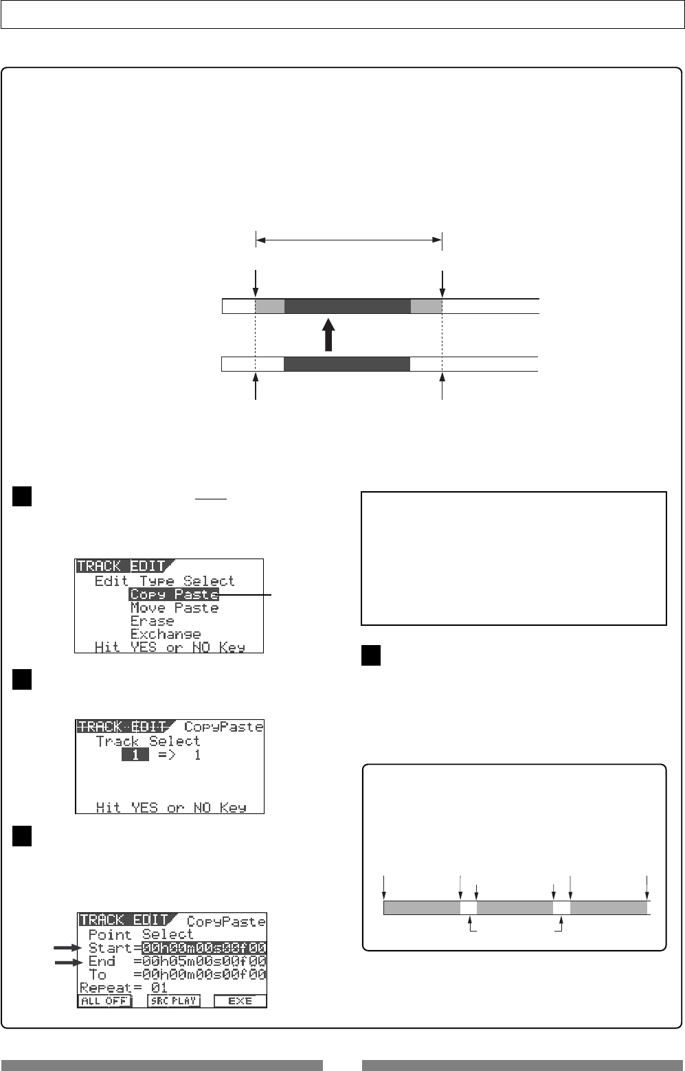
82
Advanced Operations
<About Start and End points>
As described earlier, the starting and ending times of internal mastering are automatically
registered as "Start point" and "End point" respectively, which can be used for track editing
(copy, move and erase) for the newly created program (see the illustrations below).
This function is very convenient for making an audio CD from mastered materials, because
data between "Start point" and "End point" is automatically transferred to a CD-RW/CD-R disc.
Note that you cannot make an audio CD using the VF80 save function (described later) without
setting these two points.
The "Start point" and "End point" which have been automatically set can be checked after com-
pleting mastering by the following procedure.
Press the [TRACK EDIT/PGM] key while the
VF80 is stopped.
The display shows the screen for track editing, where
"Copy Paste" flashes.
Press the [ENTER/YES] key.
The display shows the screen for selecting an origi-
nal and destination tracks for copy/paste.
Press the [ENTER/YES] key again.
The display shows the screen for selecting edit
points, in which you can check "Start" and "End"
points that hold the beginning and end points of
the recording respectively (pointed by arrows be-
low).
After checking the "Start" and "End" points,
press the [EXIT/NO] key to quit the track edit
mode.
The display returns to the previous screen before
performing step 1.
See page 115 about how to make an audio CD from
mastered materials.
<Hint>
When recording more than one song continuously
to a CD-RW/CD-R disc, the VF80 automatically
record an approximately 2-second silence after each
END point.
<Note>
You can edit the
"Start point"
and
"End point"
be-
fore creating an audio CD, allowing adjustment
of intervals between songs.
We recommend to set the
"Start point"
and "
End
point"
of the new program created by the internal
mastering to desired times before creating an
audio CD.
Silence (about 2 seconds)
Start point End point
123
Start point End point
Start point End point
Internal mastering
Start point
(automatically registered) End point
(automatically registered)
Start point of internal mastering End point of internal mastering
New program (Tracks 1 & 2)
Original program (Tracks 7 & 8)
Data transferred to a CD-RW/CD-R disc
Flashing
1
2
3
4
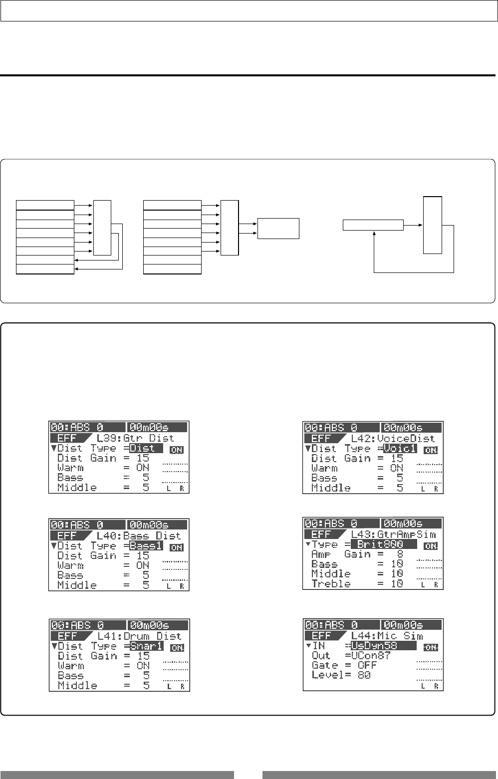
83
Advanced Operations
Unlike the loop effect described earlier in "Mixer Functions", the insert effect is applied when
rerecording any recorded track among tracks 1 through 6.
This rerecording mode in which the insert effect is applied is called "REC EFFECT" mode.
Six distortion/simulation type effects are available for the insert effect. You can distort a guitar,
bass, drums or vocal, as well as simulate a famous guitar amplifier or microphone character.
Using the insert effect
Track 1
ASP
Effect
Track 1
Track 2
Track 3
Track 4
Track 5
Track 6
Track 7
Track 8
ASP
Effect
Track 1
Track 2
Track 3
Track 4
Track 5
Track 6
Track 7
Track 8
ASP
Effect Master Recorder
<How to use the loop effect>
<Track bounce> <Mixdown>
<How to use the insert effect>
<Effect types available for the insert effect>
There are six effect types below available for the insert effect, in addition to 38 types for the loop effect as
described earlier in "Mixer Functions".
See page xx for details about parameters for each effect type.
“L39: Gtr Dist (guitar distortion)”
“L40: Bass Dist (bass distortion)”
“L41: Drum Dist (drum distortion)”
“L42: Voice Dist (voice distortion)”
“L43: Gtr Amp Sim (guitar amp simulator)”
“L44: Mic Sim (microphone simulator)”
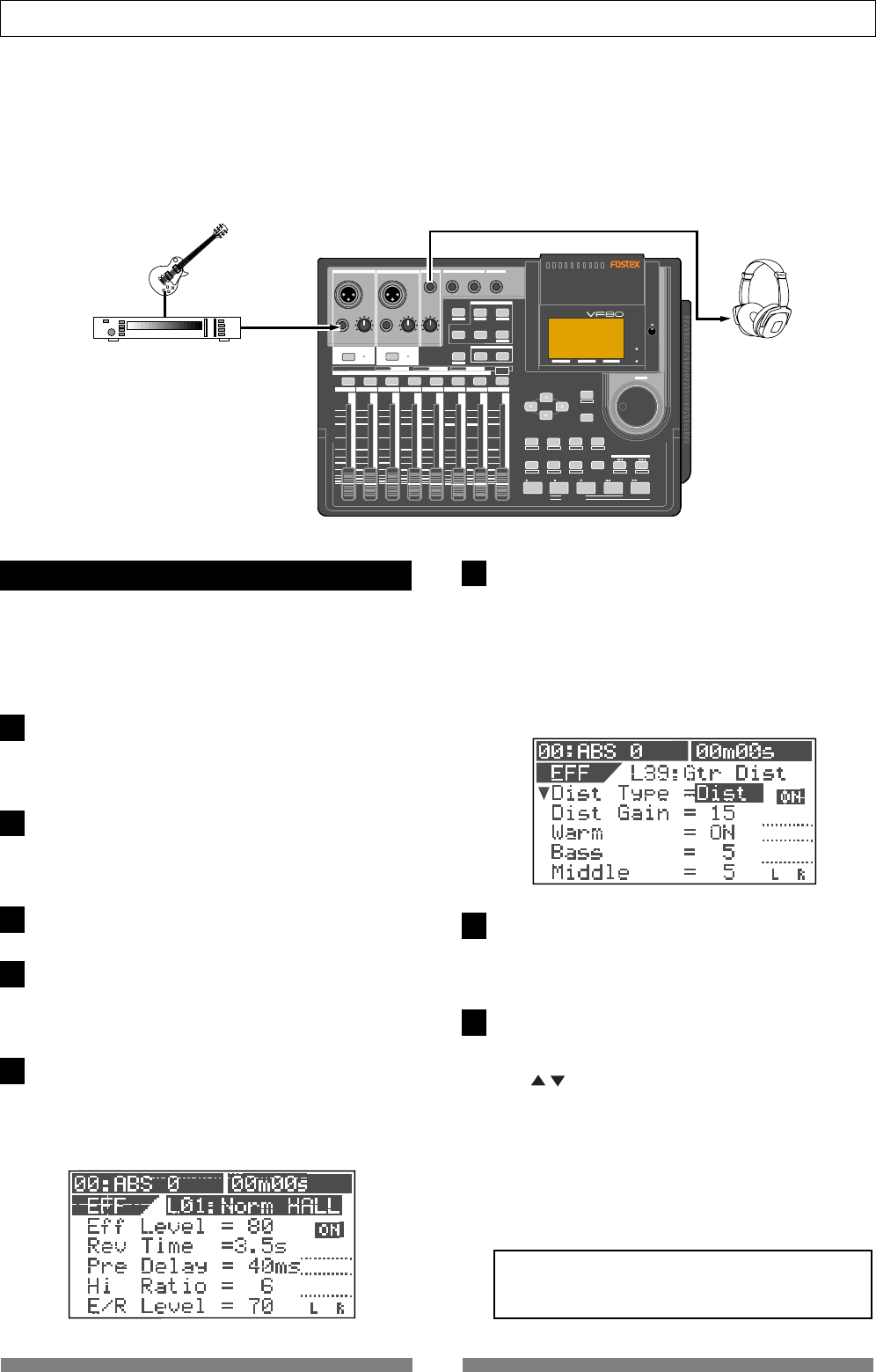
84
Advanced Operations
The following explains how to record a guitar solo to track 1 and rerecord it while applying the
guitar distortion. Before executing recording, you can check the guitar sound with the distortion
effect while rehearsing the effect parameter settings until you satisfy with the sound.
We assume that the guitar is connected to the [INPUT A] connector and the VF80 locates to the
beginning of the program (ABS 0).
DIGITAL MULTITRACKER
LOCATE ABS 0
LOCATE REC END
SEL
TIMEBASE
CURSOR
PHANTOM
ACCESS
PEAK
CH ON/OFF
LR
GUITAR
GUITAR
LINE MIC LINE MIC MIN MAX
MASTERING TRAINING
EFFECTEQPAN
SCENE SEQ.SCENE
TRACK
UNDO
SETUP
PUNCH
AUTO LOOP PITCH SCRUB
VARI
F FWDREWINDPLAYSTOPRECORD
EXIT
ENTER
TRIMTRIM
WAVE FORM
MIX PARAMETER
PGM FADER MAP
ON/OFF
2TRK MODE
F1 F2 F3 SHIFT
EDIT EDIT EDIT MARK DELETE
LOCATE
FOOT SW
ST OUT
PHONES
INPUT A
BOUNCE
INPUT B
+6
-10
-20
-40
-
∞
-30
0
+6
-10
-20
-40
-
∞
-30
0
+6
-10
-20
-40
-
∞
-30
0
+6
-10
-20
-40
-
∞
-30
0
+6
-10
-20
-40
-
∞
-30
0
+6
-10
-20
-40
-
∞
-30
0
+6
-10
-20
-40
-
∞
-30
0
+6
-10
-20
-40
-
∞
-30
0
PEAK
CH ON/OFF
2 3 4 5 6 7/8 2TRK1 MASTER
TRACK STATUS / TRACK SEL
TRACK STATUS
RED REC GREEN PLAY OFF MUTE STATUS
/SEL
EJECT
/YES
/NO
SHUTTLE
JOG
UNBAL UNBAL
BAL
BAL
F1 F2 F3
EDIT
/REDO
REC EFF
You can check the guitar sound with an effect be-
fore recording.
"L39:Gtr Dist" should be selected for the guitar dis-
tortion.
Press the [TRACK STATUS/TRACK SEL] key for
track 1 to arm track 1.
Only the [TRACK STATUS/TRACK SEL] key for track 1
flashes, while the [CH ON/OFF] key lights.
Raise the track 1 fader and [MASTER] fader to
the "0" position.
If these faders are not raised, you cannot monitor the
sound.
Press the [RECORD] key.
Track 1 is switched to "Input monitor".
Adjust the gain appropriately using the [TRIM]
control for [INPUT A] while playing the guitar.
You can monitor the guitar sound by raising the
[PHONES] control.
Press the [EFFECT] key repeatedly until the ef-
fect type selection screen appears.
When you press the [EFFECT] key for the first time
after turning on the power, "L01:Norm HALL" is shown
as the effect type.
Rehearsal
Use the [JOG] dial to select "L39: Gtr Dist" and
press the [ENTER/YES] key.
"Insert Effect Selected!" is momentarily shown on the
display, followed by the parameter setting screen for
"L39: Gtr Dist".
Meanwhile, the [TRACK STATUS/TRACK SEL] keys for
tracks 1 through 6 starts flashing, showing that you
can select a track to which the effect is inserted.
Press the [TRACK STATUS/TRACK SEL] key for
track 1.
Only the [TRACK STATUS/TRACK SEL] key for track 1
flashes, showing that track 1 is selected.
Adjust parameters while playing the guitar to get
the desired sound.
You can select a desired parameter using the [CUR-
SOR] / keys and change the value using the [JOG]
dial.
Before editing parameters, you can monitor the sound
with the default parameter settings.
The monitor sound changes in realtime when chang-
ing a parameter.
See the next page for details about the parameters for
"L39: Gtr Dist".
<Caution!>
Do not raise the headphones volume too loud while
monitoring the sound, which may damage your ears.
1
2
3
4
5
6
7
8
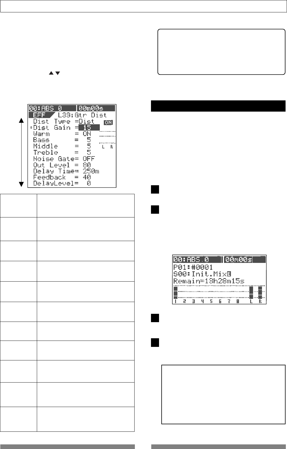
85
Advanced Operations
<How to edit parameters>
The "L39: Gtr Dist" effect type has 11 parameters as
shown below. (Note that the screen example below
shows all parameters for the explanation. Actually,
you can see 5 parameters at a time while the other
parameters are hidden.)
Use the [CURSOR] / keys to select a highlighted
parameter. Use the [JOG] dial to select the value of
the highlighted parameter.
The monitor sound changes in realtime when chang-
ing a parameter.
1. Dist Type
Selects a distortion type.
Options: Acous, Rythm, OvDrv, Dist, Blues,
Fuzz, Lead, Metal (Default: Dist)
2. Dist Gain
3. Warm
Adjusts the distortion gain.
Range: 1 to 15 (The default depends on
the distortion type selected.)
4. Bass
Makes the sound warmer when On.
Options: ON, OFF (default: ON)
5. Middle
Adjusts the low frequency response.
Range: 0 to 10 (default: 5)
6. Treble
Adjusts the mid frequency response.
Range: 0 to 10 (default: 5)
7. Noise Gate
Adjusts the high frequency response.
Range: 0 to 10 (default: 5)
8. Out Level
Turns on or off the noise gate.
Options: OFF, 1 to 99 (default: OFF)
9. Delay Time
Sets the output level of the distortion.
Range: 0 to 99 (default: 80)
10. Feedback
Sets the delay time.
Range: 5 ms to 1200 ms (default: 250 ms)
11. Delay Level
Sets the feedback level of the distortion.
Range: 0 to 99 (default: 40)
Sets the delay level.
Range: 0 to 99 (default: 0)
<Storing parameter settings>
It will be a good idea to store a favorite pa-
rameter setting to a scene.
You can recall a stored setting whenever you
like. See page 52 for details about the scene
memory.
After making desired effect parameter settings in
rehearsal, record the guitar while monitoring the
effected sound.
Note that the dry sound is recorded though you
monitor the wet sound.
We assume that track 1 is "Input monitor" (i.e. the
[RECORD] key and the [TRACK STATUS/TRACK SEL]
key for track 1 are flashing).
Recording the guitar
Press the [EXIT/NO] key to switch to the Normal
screen.
Press the [PLAY] key while holding down the
[RECORD] key to start recording and play the
guitar.
The dry sound is recorded to track 1 while the wet
sound is monitored.
The screen shows both the recording level of the gui-
tar and the monitor level.
Press the [STOP] key to stop recording.
The [TRACK STATUS/TRACK SEL] key for track 1 still
flashes, while the [RECORD] key turns off.
Press the [REWIND] key while holding down the
[STOP] key to locate to the beginning of the pro-
gram.
<To playback the recorded sound>
To check the recorded "
dry
" sound just re-
corded, press the
[EFFECT]
key while holding
down the
[SHIFT]
key to turn off the effect,
then press
[PLAY]
key to start playback.
If you do not turn off the effect, the "
wet
"
playback sound is monitored with the effect
you set in rehearsal.
1
2
3
4
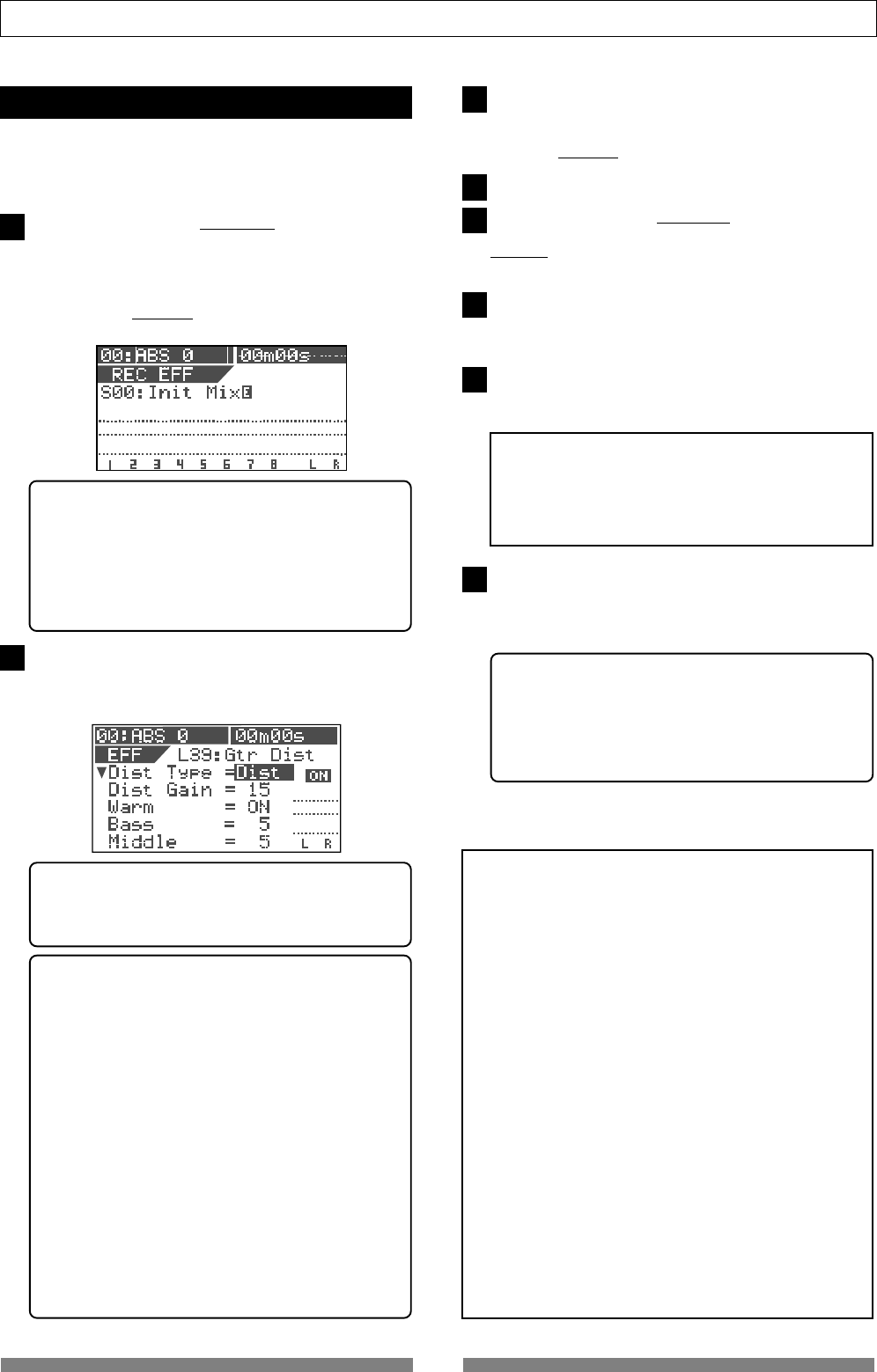
86
Advanced Operations
The final step is to rerecord the recorded "dry" sound
on track 1 while applying the effect (guitar distor-
tion) with the setting you made in rehearsal.
Rerecording with effect
Press the [BOUNCE/REC EFF] key while hold-
ing down the [SHIFT] key.
The unit enter the REC EFFECT mode, in which you
can apply the insert effect. The screen shows some-
thing like below.
The [BOUNCE/REC EFF] key and the [TRACK STATUS/
TRACK SEL] key for track 1 flash.
Press the [PLAY] key to start playback from the
beginning of the program.
You can confirm that the "dry" sound on track 1 is
replaced with the "wet" sound.
<Note>
Before playing back the rerecorded sound, always
turn off the effect by the above operation.
If you playback the rerecorded sound while the ef-
fect is set to
ON
, you will monitor the "
wet
" sound
with applying the effect.
<To cancel recording>
If you are not satisfied with the result, press the
[UNDO/REDO] key to undo the last recording, and
make recording again. Pressing the [UNDO/REDO]
key once returns track 1 to the "dry" sound.
Pressing the [UNDO/REDO] key again returns track 1
back to the "wet" sound.
Press the [PLAY] key while holding down the
[RECORD] key to start recording.
During recording in the “REC EFFECT mode”, the
[BOUNCE/REC EFF] key is flashing in red.
Press the [STOP] key to stop recording.
Press the [BOUNCE/REC EFF] key.
The unit exits the REC EFFECT mode, and the [BOUNCE/
REC EFF] key turns off, while the [TRACK STATUS/TRACK
SEL] key for track 1 lights steadily in green.
Press the [REWIND] key while holding down the
[STOP] key to locate to the beginning of the pro-
gram.
Press the [EFFECT] key while holding down the
[SHIFT] key to turn off the effect.
The [EFFECT] key turns off.
Press the [EFFECT] key.
The effect type selection screen appears, where "L39
Gtr Dist" is selected. All parameter are set as you did
during rehearsal.
<Selecting a recording track>
When entering the REC EFFECT mode, the [TRACK
STATUS/TRACK SEL] key for track 1 flashes. You can
select any track to be recorded from among tracks
1 through 6 by pressing the appropriate [TRACK
STATUS/TRACK SEL] key.
In this example, you are going to record to track 1,
so you do not have to change the setting.
<Make sure that the effect is set to ON>
If the effect is set to OFF, press the [EFFECT] key
while holding down the [SHIFT] key to switch it to
ON.
<Check the recording level>
When applying the insert effect, you can adjust the
recording level by the "Out Level" parameter.
Before starting recording, check/adjust the record-
ing level by following the procedure below. Note
that the channel fader, [MASTER] fader, EQ and pan
only affect the monitor sound.
1. Use the [JOG] dial to highlight the "Out Level"
parameter.
2. Press the [RECORD] key to monitor the input.
3. Press the [PLAY] key to start playback from the
beginning.
4. While monitoring the playback sound with
applying the effect, adjust the "Out Level" value
appropriately using the [JOG] dial so that the
PEAK indicator does not light frequently.
5. After setting the level, locate to the beginning of
the program.
<Notes for the REC EFFECT mode>
• In the REC EFFECT mode, you can select an effect type
only from among
L39 through L44
.
If you enter the REC EFFECT mode from the
condition in which an effect type for the loop effect
is selected, "
L39: Gtr Dist
" will be initially selected.
• In the REC EFFECT mode, if you recall a scene in which
the loop effect is used, the effect type is not changed.
Or, when a track the insert effect is applied to is
selected, if you recall a scene in which a track the
insert effect is applied to is selected, the track
selection is not recalled. In such a case, use the
[TRACK
STATUS/TRACK SEL]
key to change the selection.
• In the REC EFFECT mode, You cannot set "
Scene
Sequence
" and "
Digital In
" to
ON
. If you enter the
REC EFFECT mode while one or both of these are set
to ON, the unit automatically sets it (them) to OFF.
• In the REC EFFECT mode, you cannot playback or
record tracks 7 and 8 (the
[TRACK STATUS/TRACK
SEL]
keys never light up).
• To rerecord a desired part of a track with applying
the insert effect, it will be a good idea to use the auto
punch-in/out function. See page
33
for details about
the auto punch-in/out.
If you like, try recording in the similar manner by select-
ing the other effect type.
1
2
3
4
5
6
7
8
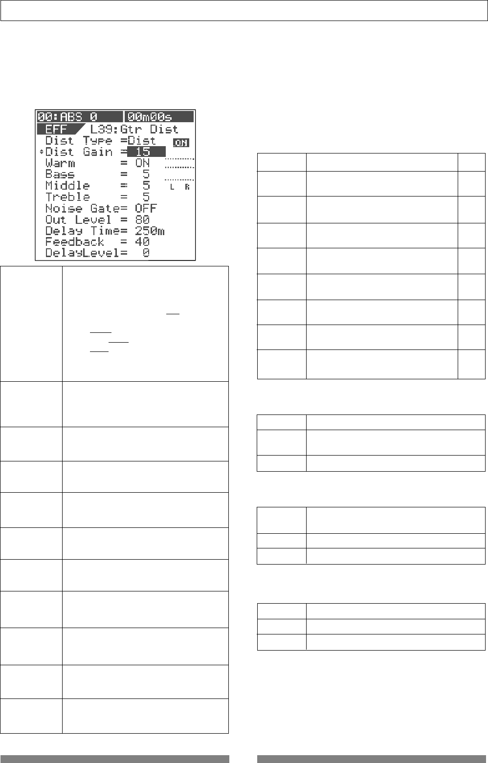
87
Advanced Operations
• Parameters for distortion effects
(Parameter type: DISTORTION)
Effect types No.39 through 42 (shown in "Effect type list" on
page 49) are distortion types.
Each of these has 11 parameters as shown below.
1. Dist Type
Selects a distortion type.
Each effect type has following distortion
type options. (An underlined option is
the default.)
L39: Acous, Rythm, OvDrv, Dist, Blues, Fuzz,
Lead, Metal
L40: Bass1, Bass2, Bass3
L41: Kick, Snar1, Snar2
L42: Voic1, Voic2, Voic3
See the table on the right for details
about each type.
2. Dist Gain
3. Warm
Adjusts the distortion gain.
Range: 1 to 15 (The default depends on
the distortion type selected. See the table
on the right.)
4. Bass
Makes the sound warmer when On.
Options: ON, OFF (default: ON)
5. Middle
Adjusts the low frequency response.
Range: 0 to 10 (default: 5)
6. Treble
Adjusts the mid frequency response.
Range: 0 to 10 (default: 5)
7. Noise Gate
Adjusts the high frequency response.
Range: 0 to 10 (default: 5)
8. Out Level
Turns on or off the noise gate.
Options: OFF, 1 to 99 (default: OFF)
9. Delay Time
Sets the output level of the distortion.
Range: 0 to 99 (default: 80)
10. Feedback
Sets the delay time.
Range: 5 ms to 1200 ms (default: 250 ms)
11. Delay Level
Sets the feedback level of the distortion.
Range: 0 to 99 (default: 40)
Sets the delay level.
Range: 0 to 99 (default: 0)
Acoustic You can get an electric-acoustic
guitar sound
Rhythm You can get a slight distortion when
picking the guitar strongly.
Over Drive You can get a smooth distortion like
driving a tube amplifier.
Distortion You can get a hard distortion like
driving a three-stacked amplifier.
Blues You can get a fat overdrive sound.
Fuzz You can get a rough sound with a fat
low frequency range.
Lead You can get a bright and smooth
distortion.
Metal You can get a shred sound.
Bass 1 Simulates a bass amplifier.
Bass 2 You can get a sound like recording a
distorted bass sound through a line.
Bass 3 You can get a fat bass sound.
Kick You can distort a kick sound
appropriately.
Snar 1 You can distort a snar sound appropriately.
Snar 2 You can distort a snar sound excessively.
Voic 1 You can get a smooth distortion.
Voic 2 You can get a boomy and bright distortion.
Voic 3 You can get a bullhorn sound.
Details of each distortion type
Each distortion type (selectable for each of effect
types No.39 through 42) can apply the effect as de-
scribed below.
• Distortion types for "L39: Gtr Dist"
The default distortion gain value depends on the
distortion type selected.
• Distortion types for "L40: Bass Dist"
• Distortion types for "L41: Drum Dist"
• Distortion types for "L42: Voice Dist"
1
4
15
15
15
15
15
15
Name Comment Default
Dist Gain
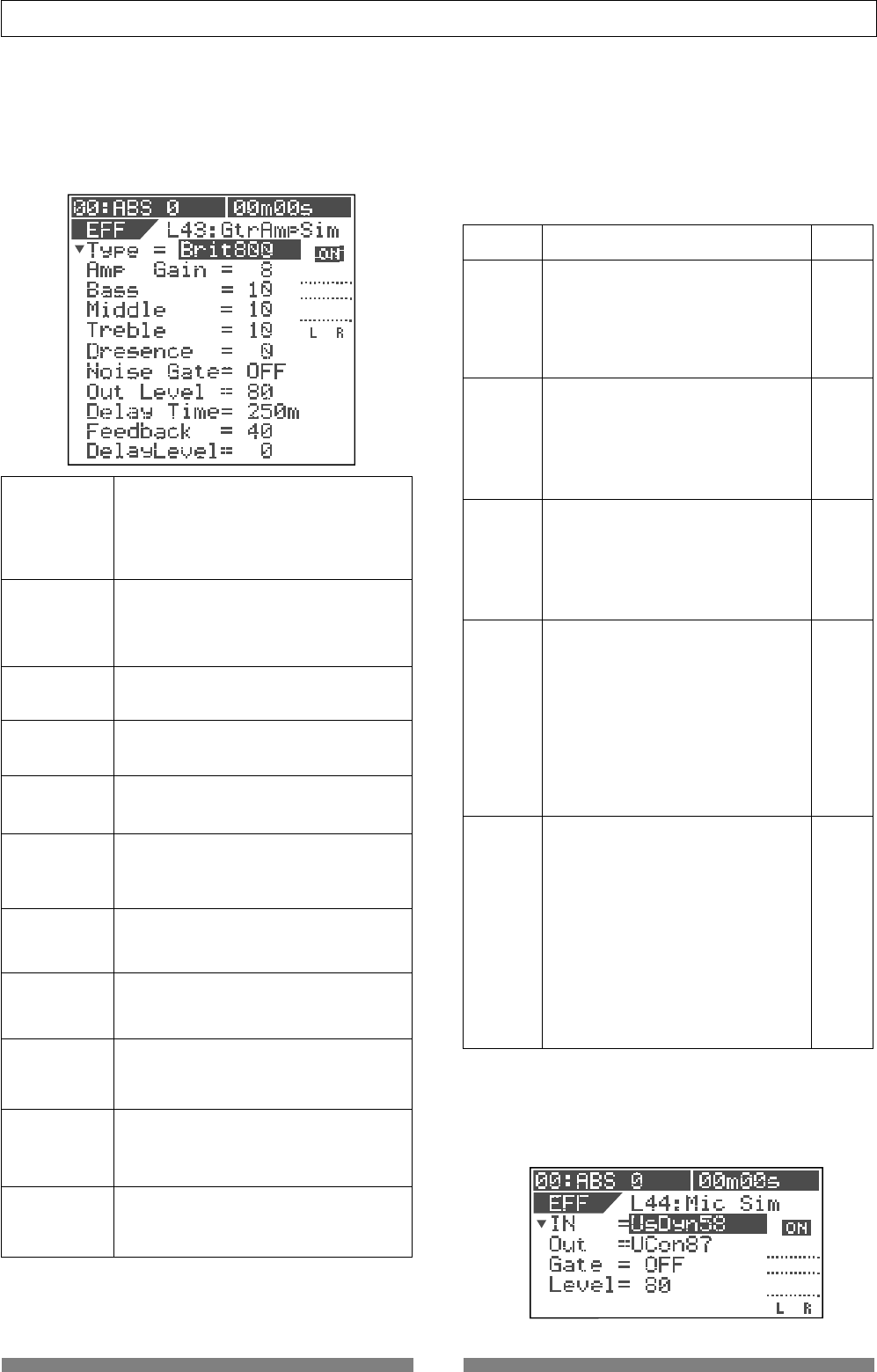
88
Advanced Operations
• Parameters for distortion effects
(Parameter type: AMP SIMULATION)
Effect type No.43 (shown in "Effect type list" on page 49) is
the amp simulation type.
This effect type has 11 parameters as shown below.
1. Type
Selects an amplifier type to be simulated.
Options: Brit800, TremoRect, MetalRect,
ClassA30, Fatman (default: Brit800)
See the table on the right for details
about each type.
2. Amp Gain
3. Bass
Adjusts the distortion gain.
Range: 1 to 15 (The default depends on
the distortion type selected. See the table
on the right.)
4. Middle
Adjusts the low frequency response.
Range: 0 to 10 (default: 10)
5. Treble
Adjusts the mid frequency response.
Range: 0 to 10 (default: 10)
6. Presence
Adjusts the high frequency response.
Range: 0 to 10 (default: 10)
7. Noise Gate
Adjusts the presence (the feeling of be-
ing "up front").
Range: 0 to 10 (default: 0)
8. Out Level
Turns on or off the noise gate.
Options: OFF, 1 to 99 (default: OFF)
9. Delay Time
Sets the output level of the distortion.
Range: 0 to 99 (default: 80)
10. Feedback
Sets the delay time.
Range: 5 ms to 1200 ms (default: 250 ms)
11. Delay Level
Sets the feedback level of the distortion.
Range: 0 to 99 (default: 40)
Sets the delay level.
Range: 0 to 99 (default: 0)
Details of each amplifier types
Five guitar amplifier types can be simulated.
Each amplifier type has its own unique character as
described below.
The default distortion gain value depends on the
amplifier type selected.
British 800 Amplifier
Simulates the 800-series British tube
amplifier, a synonym for "rock".
The king of the rock sound of the
80's hard rock and heavy metal.
Distorted raging sound.
Tremo Rect Amplifier
Simulates the American combo
model amplifier, designed to get
high gain sound for the 90's hard
rock and heavy metal.
Fat bass and raging distorted sound.
Metal Panel Recti Amplifier
Simulates the amp head of the high
gain amp series, same as the Tremo
Recti Amplifiers. Deep and well-sepa-
rated distortion and heavy sound.
Suitable for the metal sound.
British Class A 30 Amplifier
Simulates a most popular British
sound tube amplifier.
The preamp section is designed us-
ing the class A circuit for creating
the fat and warm sound.
Usually used in the range between
clear and crunch sound, but some-
times used with the higher gain to
get a harder distortion.
Fat Bass Amplifier
Simulates the American combo am-
plifier designed as a bass amplifier
but used by many guitarists because
of its fat presence sound.
Suitable for jazz and blues with its
clear and crunch sound, however,
because you can get a raging distor-
tion that you cannot expect from an
ordinary bass amplifier when rais-
ing the gain, It can be used for a wide
range of genres.
Name Comment Default
Amp Gain
8
15
15
2
5
• Parameters for distortion effects
(Parameter type: MIC SIMULATION)
Effect type No.44 (shown in "Effect type list" on page
49) is the mic simulation type.
This effect type has 3 parameters as shown below.
Brit800
TremoRect
MetalRect
ClassA30
FatMan
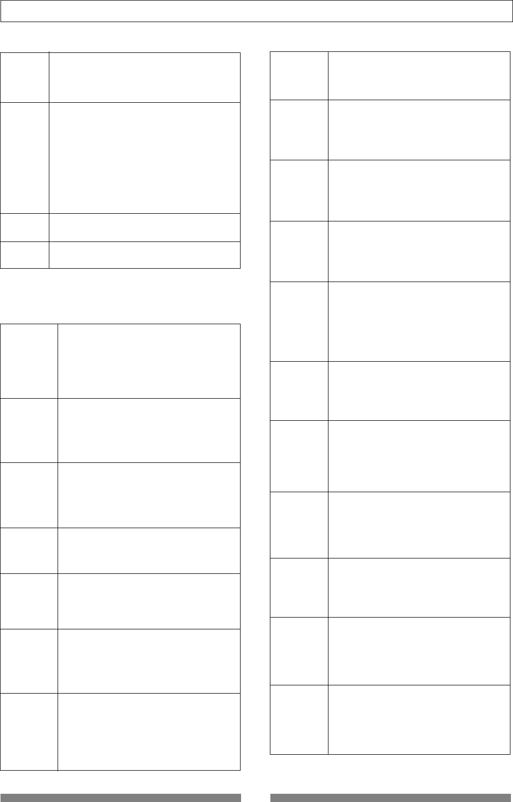
89
Advanced Operations
TCon 3k
Trad Condenser 3k (Low cut: Off)
Simulates the sound of a multipurpose
professional condenser microphone with
a large diaphragm.
Its warm and transparent sound is suit-
able for a vocal, as well as a drum over-
head or guitar amplifier.
TCon 3k LC
Trad Condenser 3k (Low cut: On)
Simulates the sound of "TCon 3k" above
with the Low Cut switch to On.
You can suppress boosted low frequencies
as a result from placing a microphone in
close proximity to the signal source.
TCon 414
Trad Condenser 414 (Low cut: On)
Simulates the sound of one of the most
popular condenser microphones in profes-
sional studios together with the Classic
condenser 87. You can get a high-fidelity
clean sound of an acoustic piano.
TCon 414 LC1
Trad Condenser 414 (Low cut: 75 Hz)
Simulates the sound of "TCon 414" above
with the Low Cut switch to On (75 Hz).
You can suppress boosted low frequencies.
TCon 414 LC2
Trad Condenser 414 (Low cut: 150 Hz)
Simulates the sound of "TCon 414" above
with the Low Cut switch to On (150 Hz).
You can suppress boosted low frequencies
more than "TCon 414LC1".
TDyn 112
Trad Dynamic 112
Simulates the sound of a dynamic micro-
phone suitable for a kick.
You can get a clean and powerful sound
by applying it to a kick or bass.
It has a slightly boosted low frequencies.
Details of microphone output types
18 options are available for the microphone output
type, as shown below.
1. IN
Selects a microphone input type.
Options: US Dyn 58 (dynamic type), MCon2
(condenser type)
Default: US Dyn 58
2. Out
3. Gate
Selects a microphone output type to be simu-
lated.
Options: TCon3k, TCon3k LC, TCon414,
TCon414LC1, TCon414LC2, TDyn112, GDyn421,
GDyn421LC3, GDyn421LC2, GDyn421LC1,
GDyn421SPE, MCon1, MCon2, MConV, UsDyn58,
VCon47, VCon87, VCon87 LC
Default: VCon87
See the next page for details.
Adjusts the noise gate.
Options: OFF, 0 to 99 (default: OFF)
4. Out Level Sets the output level.
Range: 0 to 99 (default: 80)
GDyn 421
German Dynamic 421
Simulates the sound of a dynamic micro-
phone which is frequently used for record-
ing a tom-tom.
Suitable for recording a skin percussion
because of its powerful attack feeling with
a high frequency peak.
GDyn 421 LC3
German Dynamic 421 (Low cut: 3)
Simulates the sound of "GDyn 421" above
with the Low Cut switch to On (3).
You can suppress boosted low frequencies.
GDyn 421 LC2
German Dynamic 421 (Low cut: 2)
Simulates the sound of "GDyn 421" above
with the Low Cut switch to On (2).
You can suppress boosted low frequencies
more than "GDyn 421 LC3".
GDyn 421 LC1
German Dynamic 421 (Low cut: 1)
Simulates the sound of "GDyn 421" above
with the Low Cut switch to On (1).
You can suppress boosted low frequencies
more than "GDyn 421 LC2".
GDyn 421 SPE
German Dynamic 421 (Low cut: SPE)
Simulates the sound of "GDyn 421" above
with the Low Cut switch to On (SPE).
You can considerably suppress boosted low
frequencies. Suitable for a speech.
MCon 1
Modern Condenser 1
Simulates the sound of a modern con-
denser microphone which has a wider dy-
namic range and bright sound. It offers a
warm tube sound, making a vocal or acous-
tic guitar as if it were recorded by a con-
denser microphone.
MCon 2
Modern Condenser 2
Simulates the sound of a condenser micro-
phone offering wide dynamic range, like
"MCon 1". It offers a flat frequency re-
sponse and natural sound.
MCon V
Modern Condenser V
Simulates the sound of a modern tube mi-
crophone with vintage feel.
It offers a deep and natural sound which
only tube microphones can provide.
Suitable for a vocal, piano and ensemble.
Us Dyn 58
US Dynamic 58
Simulates the most popular dynamic hand-
held vocal microphone.
High-end and low-end frequencies are not
extended as compared with a condenser
microphone.
VCon 47
Vintage Condenser 47
Simulates a professional tube microphone
with a large diaphragm that offers clean
and dry sound.
Suitable for an acoustic guitar and brass.
VCon 87
Vintage Condenser 87 (Low cut: Off)
Simulates the sound of a classic and his-
toric model used for vocals and strings fre-
quently in professional studios.
Provides outstanding warm sound among
condenser microphones.
VCon 87 LC
Vintage Condenser 87 (Low cut: On)
Simulates the sound of "VCon 87" with low
cut "On".
You can suppress boosted low frequencies
as a result from placing a microphone in
close proximity to the signal source.
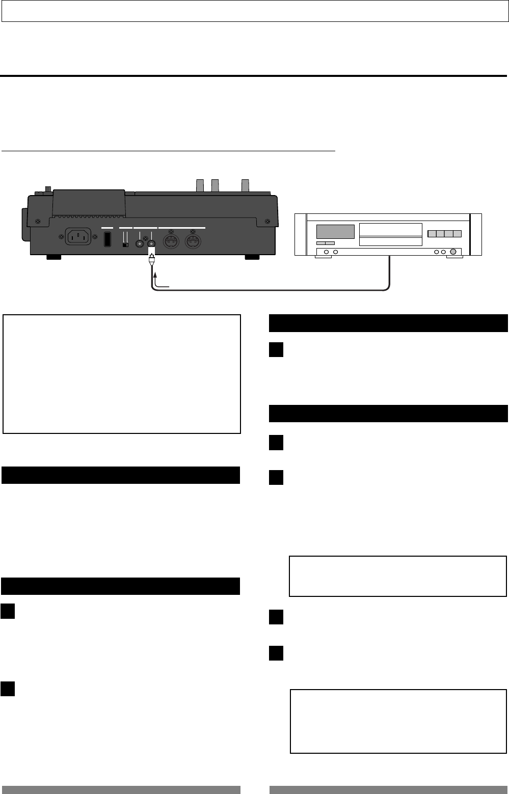
90
Advanced Operations
OFF
ON
MIDI
OUTPUT INPUT OUTPUT
INPUT
POWER PHANTOM S/P DIF / DATA
1
2
1
1
2
3
4
Digital recording
You can digitally record an external digital source to the VF80, or stereo output signals of the VF80 to an external
digital recorder. This section describes how to make digital recording between the VF80 and an external digital
device. Note that the VF80 can only handle S/P DIF format digital data.
Recording an external source onto the VF80 digitally
The following describes how to record an external S/P DIF digital source (such as CD, MD and DAT) onto the
VF80.
<Important note>
• When recording a digital source onto the VF80, make
sure that the source signal is the "
44.1 kHz, 16-bit
" S/P
DIF digital format.
• You can record an external S/P DIF digital source only
onto Tracks 7/8 of the VF80. If you want to record it
onto other tracks, first record it onto Tracks 7/8 and
then move the data to other tracks using the track
exchange function.
Selecting a program to be recorded
When more than one program exists, select the desired
program using the program select function before re-
cording.
See "Selecting a program" in "Recorder function" about
how to select a program.
Selecting the digital input
In the "Digital In" menu of the setup mode, select "On."
See "Setting digital input" in "Setup mode" about how to
select "On."
When set to "On", you can record an incoming S/P DIF
signal from the [S/P DIF / DATA INPUT] connector onto
Track 7/8 of the VF80.
After setting "Digital In" menu, press the [EXIT/NO] key
to exit the setup mode.
When receiving a correct S/P DIF digital signal, "DIGI
IN" is shown steadily on the screen. When a correct
digital signal is not received, "DIGI IN" blinks on the
screen. In such a case, check the connection and set-
tings of the external source device.
Selecting a track to record
Press the [TRACK STATUS/TRACK SEL] key of Tracks
7/8.
The key lighting in green change to flashing in red.
Starting to record
Set the Track 7/8 and Master faders to the "0" position.
Start recording of the VF80 by pressing the [PLAY] key
while holding down the [RECORD] key, and start play-
back of the external digital device.
"When recording a digital signal, you cannot adjust the
input level of the VF80." "To get the optimum record-
ing level, adjust the output level of the source."
The level meters for Tracks 7/8 on the screen shows
the input levels.
<Note>
During digital recording, the level meters for the
stereo outputs (L and R) are not active.
Rotating the [PHONES] knob clockwise to monitor the
source sound.
After finishing recording, stop the VF80 by pressing
the [STOP] key , as well as stop the external digital de-
vice.
<Note>
After you have finished the digital recording, return
the "Digital In" setting to "
Off.
"
When "
On
", you cannot record any analog signal
onto Tracks 7/8.
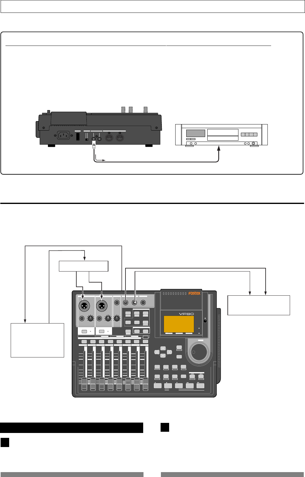
91
Advanced Operations
OFF
ON
MIDI
OUTPUT INPUT OUTPUT INPUT
POWER PHANTOM S/P DIF / DATA
DIGITAL MULTITRACKER
LOCATE ABS 0
LOCATE REC END
SEL
TIMEBASE
CURSOR
PHANTOM
ACCESS
PEAK
CH ON/OFF
LR
GUITAR
GUITAR
LINE MIC LINE MIC MIN MAX
MASTERING TRAINING
EFFECTEQPA N
SCENE SEQ.SCENE
TRACK
UNDO
SETUP
PUNCH
AUTO LOOP PITCH SCRUB
VARI
F FWDREWINDPLAYSTOPRECORD
EXIT
ENTER
TRIMTRIM
WAVE FORM
MIX PARAMETER
PGM FADER MAP
ON/OFF
2TRK MODE
F1 F2 F3 SHIFT
EDIT EDIT EDIT MARK DELETE
LOCATE
FOOT SW
ST OUT
PHONES
INPUT A
BOUNCE
INPUT B
+6
-10
-20
-40
-
∞
-30
0
+6
-10
-20
-40
-
∞
-30
0
+6
-10
-20
-40
-
∞
-30
0
+6
-10
-20
-40
-
∞
-30
0
+6
-10
-20
-40
-
∞
-30
0
+6
-10
-20
-40
-
∞
-30
0
+6
-10
-20
-40
-
∞
-30
0
+6
-10
-20
-40
-
∞
-30
0
PEAK
CH ON/OFF
2345 6 7/8 2TRK1 MASTER
TRACK STATUS / TRACK SEL
TRACK STATUS
RED REC GREEN PLAY OFF MUTE STATUS
/SEL
EJECT
/YES
/NO
SHUTTLE
JOG
UNBAL UNBAL
BAL
BAL
F1 F2 F3
EDIT
/REDO
REC EFF
ST OUT L, R
MIDI IN MIDI OUT
MIDI IN
MIDI Sound Source
MIDI Sequencer
MIDI OUT
Master Recorder
MIDI clock & song position ponter
INPUT
1
2
Recording the VF80 stereo output signals digitally onto an external digital device
You can record the stereo output signal digitally onto an external digital device via the [S/P DIF/DATA OUTPUT]
connector.
You do not have to carry out any special operation for outputting an S/P DIF digital signal from the [S/P DIF/
DATA OUTPUT] connector, because it is always output there.
All you have to do for mixing down to an external digital device digitally is to connect the device to the [S/
P DIF/DATA OUTPUT] connector. You can perform the digital mixdown during the mixdown process described
in "Mixdown" of the "Basic recording/playback" chapter as well as in the mastering mode described in "Master-
ing mode" of this chapter.
MIDI clock sync system
By setting any desired meter at any desired point of the programmable tempo map contained in the VF80, and
by output of a MIDI clock and song position pointer according to the setting, a hardware type MIDI sequencer
can be synchronized as a MIDI clock slave. Consequently, in this system, the VF80 will be the master and the MIDI
sequencer the slave.
Connecting external equipment
Connect the VF80 MIDI OUT to MIDI IN of the MIDI
sequencer.
Set the MIDI sequencer for “external sync mode
(EXTERNAL SYNC) by MIDI clock.”
Refer to the Owners Manual of the equipment in use
for details.
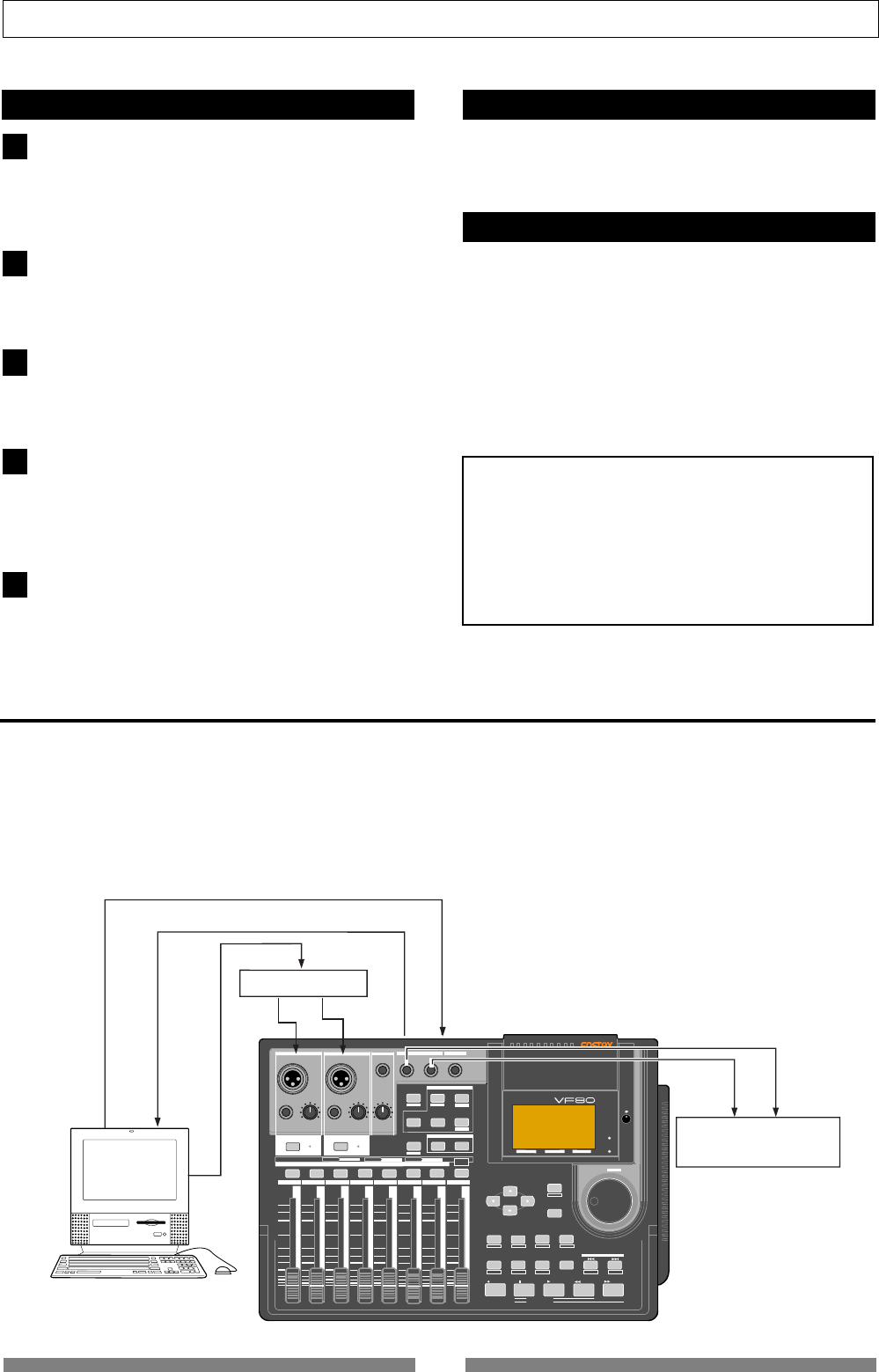
92
Advanced Operations
DIGITAL MULTITRACKER
LOCATE ABS 0
LOCATE REC END
SEL
TIMEBASE
CURSOR
PHANTOM
ACCESS
PEAK
CH ON/OFF
LR
GUITAR
GUITAR
LINE MIC LINE MIC MIN MAX
MASTERING TRAINING
EFFECTEQPA N
SCENE SEQ.SCENE
TRACK
UNDO
SETUP
PUNCH
AUTO LOOP PITCH SCRUB
VARI
F FWDREWINDPLAYSTOPRECORD
EXIT
ENTER
TRIMTRIM
WAVE FORM
MIX PARAMETER
PGM FADER MAP
ON/OFF
2TRK MODE
F1 F2 F3 SHIFT
EDIT EDIT EDIT MARK DELETE
LOCATE
FOOT SW
ST OUT
PHONES
INPUT A
BOUNCE
INPUT B
+6
-10
-20
-40
-
∞
-30
0
+6
-10
-20
-40
-
∞
-30
0
+6
-10
-20
-40
-
∞
-30
0
+6
-10
-20
-40
-
∞
-30
0
+6
-10
-20
-40
-
∞
-30
0
+6
-10
-20
-40
-
∞
-30
0
+6
-10
-20
-40
-
∞
-30
0
+6
-10
-20
-40
-
∞
-30
0
PEAK
CH ON/OFF
2 3 4 5 6 7/8 2TRK1 MASTER
TRACK STATUS / TRACK SEL
TRACK STATUS RED REC GREEN PLAY OFF MUTE STATUS
/SEL
EJECT
/YES
/NO
SHUTTLE
JOG
UNBAL UNBAL
BAL
BAL
F1 F2 F3
EDIT
/REDO
REC EFF
ST OUT L, R
MIDI IN
MIDI Sound Source
MIDI OUT
MMC
Computer System
with
MMC/MTC software
MIDI OUT
MIDI IN
MIDI OUT
MIDI IN
Master Recorder
1
2
3
4
Setup of the VF80
Because the MIDI clock and song position pointer will
be output from the VF80, set the SETUP mode “MIDI
sync signal output setting” to “CLK.”
Refer to page “126”, SETUP mode “MIDI sync signal output
setting” for correct operating procedures.
The meter in the desired bar can be set by “Time
signature setting” of the SETUP mode.
Refer to page “122”, SETUP mode “Time Signature Setting”
for operating procedure.
Tempo in the desired bar can be set by “Tempo setting”
of the SETUP mode.
Refer to page “124”, SETUP mode “Tempo Setting” for
operating procedure.
Set the SETUP mode “Metronome setting” to “On” if
click sound is to be output according to the setup
tempo map.
Refer to page “125”, SETUP mode “Metronome setting” for
operating procedure.
5
Confirming the MIDI clock sync
During recording and at playback following the
recording, the time base (BAR/BEAT/CLK) is displayed
in accordance to the setup tempo map, and the MIDI
clock and song position pointer is also output.
Confirm that the travel position (BAR/BEAT/CLK) of
the VF08 and the travel position of the synchronized
MIDI sequencer are matched.
If correct sync cannot be obtained, re-check the
connections/cables and setting of both equipment.
<Note>
In the VF80, the “ABS 0” position is set at “-002BAR/1BEAT
/00CLK.” This setting is made in consideration of the
time required (it will not sync immediately) for the MIDI
sequencer, etc. to enter into sync. As a result, if the VF80
is played back from ABS 0 (LOCATE ABS 0), sync will be
completed by the time it reaches the first bar, and will
thus synchronize from head of the tune.
Press the [TIME BASE SEL] key, and then change the
time base display to BAR/BEAT/CLK.
Various ways of recording can be conducted while
synchronizing the VF80 and the MIDI sequencer with
the MIDI clock.
Executing of recording
MTC sync/MIDI machine control system
The following will explain synchronization by the MTC (MIDI time code) output and the computer controlling
system using MMC (MIDI machine control). In this system, the VF80 will be the master and the computer (with
sequence software) will be the slave. The VF80 will attach any desired offset (time difference) against ABS time
(absolute time) and output it as MTC in any desired frame rate. It can also carry out the proper operation upon
receiving an MMC from outside. In this case, because the VF80 can setup a DEVICE ID number by the SETUP mode
“MIDI Device ID Setting” menu, a multiple number of the VF80’s can be separately controlled by changing the DEVICE
ID numbers in the transmitted message from the computer.
93
Advanced Operations
1
1
1
2
3
4
5
6
1
2
Connecting to external equipment
Connect the VF80 MIDI IN/OUT to the computer (with
MIDI interface) MIDI IN/OUT.
MMC/MTC complied sequence software is activated in
the computer.
Setup of external equipment
Setup the following in the sequence software.
* Set to MTC external sync mode (EXTERNAL SYNC).
* Set for output of MMC.
* Set to the desired MTC read out frame rate.
* Set start time of the tune (which MTC time is to be the first
bar). Refer to precaution in regards to MTC offset, farther
on.
For details, refer to Owners Manual of the external
equipment.
Setup of the VF80
Because MTC will be output from the VF80, set to “MTC”
the SETUP mode “MIDI sync signal output setting.”
Refer to page “126”, SETUP mode “MIDI sync signal output
setting” for operating procedure.
Set a random offset time by the SETUP mode “MTC
offset time setting.”
Refer to page “127”, SETUP mode “MTC offset time setting”
for operating procedure.
In the SETUP mode “MTC offset mode setting,” whether
the MTC offset time setup in Step 2 should be output
(ABS) at the ABS 00m 00s 00f 00sf position or at the
001BAR 1BEAT 00CLK (bar, signature) must be
selected.
Refer to page “127”, SETUP mode “MTC offset mode
setting” for operating procedure.
Setup to the same frame rate as that setup by the
sequence software by “MTC Frame rate setting” of the
SETUP mode.
Refer to page “126”, SETUP mode “MTC Frame rate setting”
for operating procedure and details.
Set to the same figure as the sequence software MMC
device number by the SETUP mode “MIDI device ID
setting.”
When the sequence software transmits by “7F,” it means
“ALL DEVICE” and therefore, it need not be setup.
Refer to page “131”, SETUP mode “MIDI device ID setting”
for operating procedure and details.
Press the [TIME BASE SEL] key, and then change the
time base display to MTC.
<Notes on MTC related setups>
By “
MTC offset time setting
” and “
MTC offset mode setting
,”
at what position (ABS 0 or 001BAR/1BEAT/00CLK)
should the setup MTC (MTC offset time) is to be output
is set. When setting the start time of the tune in the
sequence software by these setups, be careful of the
following points.
• Offset mode: For ABS
If playback is started from ABS 0, since MTC will be
output starting from the MTC offset time that has been
set, the start time of the tune set by the sequence software
must be set about 3 seconds later from the MTC offset
time that was setup. This will provide time because the
sequence software cannot sync immediately after MTC
is output. For example, if the initial setting of “
00h 59m
57s 00f 00sf
” is used, set the start time of the tune to “
01h
00m 00s 00f
.”
If playback is thus started from ABS 0 (LOCATE ABS 0),
sync will be obtained by the time it reaches the first bar
and therefore it can be made to sync from the head of
the tune.
• Offset mode: For BAR
As mentioned before, because the “
ABS 0
” position is set
at the “
002BAR / 1BEAT / 00CLK
” position, the setup MTC
offset time can be set to the head of the tune without
taking into account the time until reaching sync, as
mentioned above. The length of the time two bars
beforehand will change in accordance to the first bar
setting for “
signature
” and “
tempo
.” For example, it will
be long if the tempo is set slow. This mode can be
effectively applied when using the MIDI clock and MTC
in parallel, and when using MTC for the sync signal while
controlling the recorder with time base BAR/BEAT/CLK.
Confirming MTC sync/MMC
During recording and at playback after recording, time
base MTC is displayed according to the setting and MTC
is output at the same time.
Check that the VF80 traveling position (MTC) and the
traveling position of the sequence software in sync are
matched.
Send MMC commands such as PLAY, STOP and
LOCATE from the sequence software to see that the
VF80 will be properly controlled.
When a correct MIDI command (MMC or FEX) is received,
“MIDI” in the display will be lit for about 40msec.
There is no setting in the VF80 to receive MMC but it
will operate if a correct MIDI signal is input.
If sync and control cannot be done correctly, re-check
connections/cables and the setting of both equipment.
Execution of recording
Carry out various recordings while synchronizing the
VF80 and a MIDI sequencer with the MIDI clock.
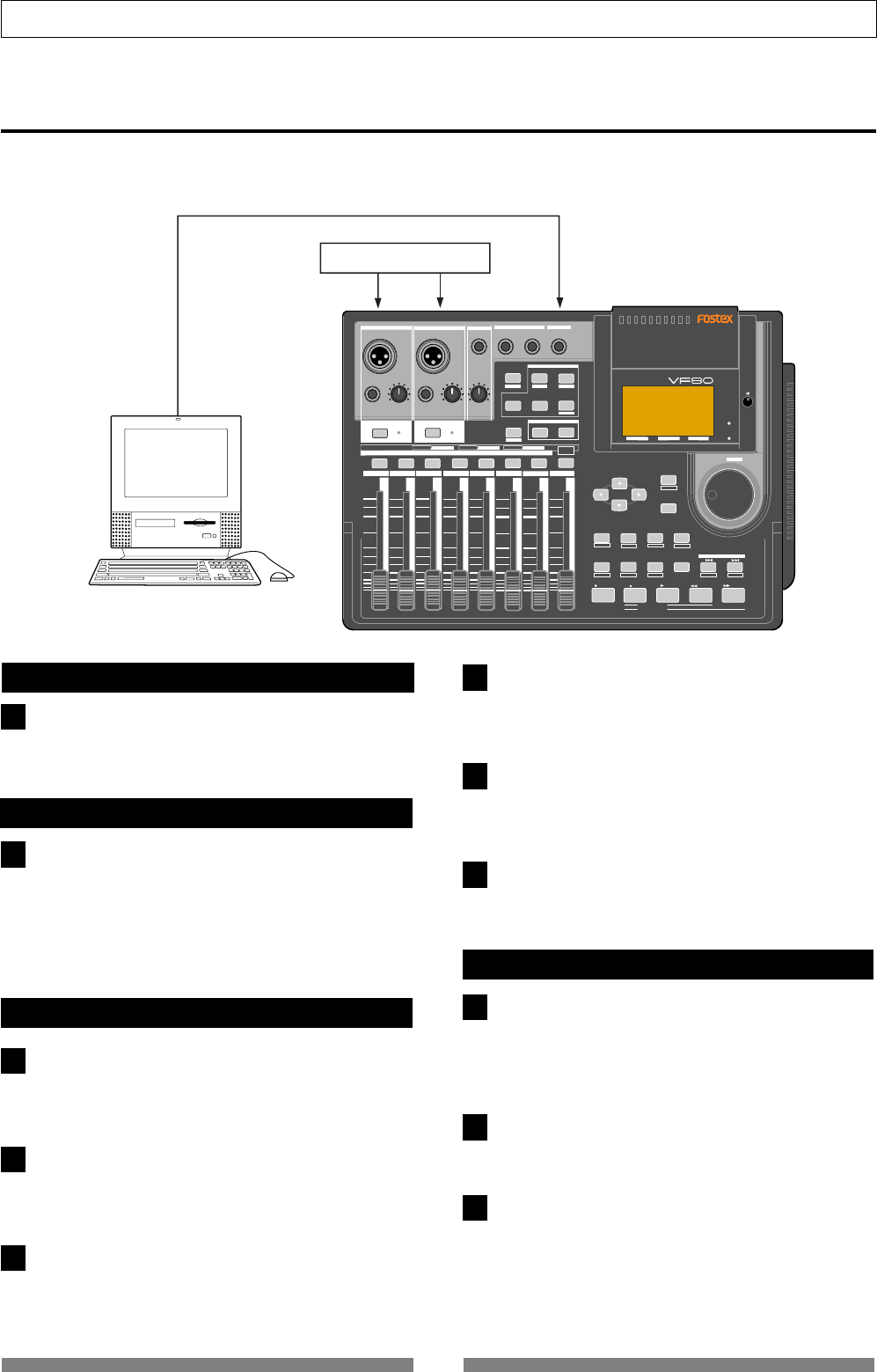
94
Advanced Operations
DIGITAL MULTITRACKER
LOCATE ABS 0
LOCATE REC END
SEL
TIMEBASE
CURSOR
PHANTOM
ACCESS
PEAK
CH ON/OFF
LR
GUITAR
GUITAR
LINE MIC LINE MIC MIN MAX
MASTERING TRAINING
EFFECTEQPAN
SCENE SEQ.SCENE
TRACK
UNDO
SETUP
PUNCH
AUTO LOOP PITCH SCRUB
VARI
F FWDREWINDPLAYSTOPRECORD
EXIT
ENTER
TRIMTRIM
WAVE FORM
MIX PARAMETER
PGM FADER MAP
ON/OFF
2TRK MODE
F1 F2 F3 SHIFT
EDIT EDIT EDIT MARK DELETE
LOCATE
FOOT SW
ST OUT
PHONES
INPUT A
BOUNCE
INPUT B
+6
-10
-20
-40
-
∞
-30
0
+6
-10
-20
-40
-
∞
-30
0
+6
-10
-20
-40
-
∞
-30
0
+6
-10
-20
-40
-
∞
-30
0
+6
-10
-20
-40
-
∞
-30
0
+6
-10
-20
-40
-
∞
-30
0
+6
-10
-20
-40
-
∞
-30
0
+6
-10
-20
-40
-
∞
-30
0
PEAK
CH ON/OFF
2345 6 7/8 2TRK1 MASTER
TRACK STATUS / TRACK SEL
TRACK STATUS
RED REC GREEN PLAY OFF MUTE STATUS
/SEL
EJECT
/YES
/NO
SHUTTLE
JOG
UNBAL UNBAL
BAL
BAL
F1 F2 F3
EDIT
/REDO
REC EFF
Sound Source
MTC
Computer System
with
MMC/MTC software
MIDI OUT
MIDI IN
INPUT
1
1
2
3
5
6
1
2
3
External MIDI equipment sync system by the slave mode
Up to this point, synchronization with external MIDI equipment has been explained with the VF80 as the master
and MIDI equipment as the slave but depending on the slave mode setting, the MIDI equipment can be set as the
master and the VF80 as the slave.
Connection to external equipment
Setup of external equipment
Connect MIDI OUT of the computer (with MIDI interface)
with MIDI IN of the VF80.
The computer sequence software complying to MMC/
MTC must be activated.
1
Sequence software is setup as follows.
* Set for output of MTC.
* Set frame rate of the MTC to be output.
* Confirm start time of the tune.
Refer to Owners Manual of the respective equipment
for details.
Setup of the VF80
Set to same frame rate as the sequence software by the
SETUP mode “MTC Frame rate setting.”
Refer to page “126”, SETUP mode “MTC Frame rate setting”
for operating procedure and details.
Set to the desired mode by the SETUP mode “MTC
offset mode setting.”
Refer to page “127”, SETUP mode “MTC offset mode
setting” for operating procedure and details.
A random offset time can be set by the SETUP mode
“MTC offset time setting.”
Refer to page “127”, SETUP mode “MTC offset time setting”
for operating procedure and details.
4Set slave mode to “On” by the SETUP mode “Slave
mode setting.”
Refer to page “128”, SETUP mode “Slave mode setting”
for operating procedure and details.
Set slave type to “Vari” by the SETUP mode “Slave type
setting.”
Refer to page “128”, SETUP mode “Slave type setting” for
operating procedure and details.
Press the [TIME BASE SEL] key, to change the time
base display to MTC.
Confirming chase lock
When the sequence software is played, “CHASE” and
“MTC” in the display will be light and the chase lock
will be completed.
Check that the MTC output by the sequence software
and MTC time displayed in the VF80 are the same.
When the sequence software stops, MTC will be
interrupted and the VF80 will also stop.
“CHASE” in the display will change from lit to blinking.
During FF/REW of the sequence software, the VF80 will
remain stopped but upon starting to record, the VF80
will immediately chase lock.
Should it not be possible to chase lock, re-check
connections / cables and all settings.

95
Advanced Operations
<Precautions at MTC related setups>
The position (ABS 0 or 001BAR/1BEAT/00CLK) when the
setup MTC (MTC offset time) should be output was setup
by the “MTC offset time setting” and “MTC offset mode
setting.” In accordance to start time of the tune set by
the sequence software, setup as explained below.
Offset mode: For ABS
Set the MTC offset time about three seconds prior to the
start time of the tune set by the sequence software.
Because the recorder cannot immediately chase lock
after input of MTC, in order to sync the unit from head
of the tune, set the preroll using the sequence software,
and playback from before the actual head of the tune to
allow the recorder to enter into sync by the time it arrives
at the head of the tune.
Offset mode: For BAR/BEAT
The MTC offset time can be set to the same time as the
start time of the tune set by the sequence software.
Because the “ABS 0” position is set at the “002BAR/1BEAT/
00CLK” position in the unit, as mentioned before, the
preceding time required for sync is already set.
The preceding time of two bar lengths could change in
length depending on the first bar’s “signature setting” and
“tempo setting” mentioned before. For example, it will
be longer if the tempo is slowed down.
Execution of recording
Carry out various recordings while the recorder is
chase locked to the sequence software.
<One Point Advice>
Sync signal “Vari” of the “Slave mode setting” menu:
When the VF80 is made to chase lock by MTC only,
variable pitch will be constantly applied by external
MTC. If a digital signal is output to an external digital
equipment from the VF80, it will not be able to follow
the speed difference (MTC speed difference of the
master) of the VF80 and the external digital equipment,
in some cases, may not be able to input a continuous
digital signal.
As a counter measure, the sync signal should be set to
“Free” by the “Slave mode setting” menu. Using this
setting, the VF80 will enter self operation by the internal
clock, after completion of chase lock, and it will be
possible to supply a stable digital signal to the external
equipment.
Under this setting, when MTC drift between the master
recorder and slave recorder exceeds 10 frames, the VF80
will assume that chase lock has been disengaged and the
slave recorder will carry out position matching again
with the master unit (re-chase operation).
During the re-chase operation, sound output will be
muted and the digital signal will also be interrupted.
If it is within 10 frames, the slave recorder will continue
to run while admitting this drift.
<Notes>
• Chase lock of the VF80 by MTC only is permissible
when speed difference of the MTC from the master is
within +/- 5.6%.
Against the MTC within this range, variable pitch will
be constantly applied internally for chasing. Chase
lock, however, will not function against MTC at a speed
difference outside this range. Also, when the master
speed difference is large, it is advised to let the VF80
learn the master speed by entering PLAY prior to
recording. By doing so, it will be lock faster from the
second and later sessions.
• Normally, when “
Setup of slave type
” is set to “
Vari
,”
the VF80 will be constantly controlled by vari-pitch
and follow the MTC, which is the master.
However, if the digital input is set to “
On
” via the SETUP
mode “
Setup of digital input
,” it will be in “
Word clock
external sync operation
” by the digital signal (S/P DIF)
that is input.
Therefore, it must be noted that when “
Setup of digital
input
” is executed, even though “
Setup of slave type
”
is set to “
Vari
,” it will not follow by application of vari-
pitch and upon completion of lock, it will change to
external sync operation by the digital input signal.
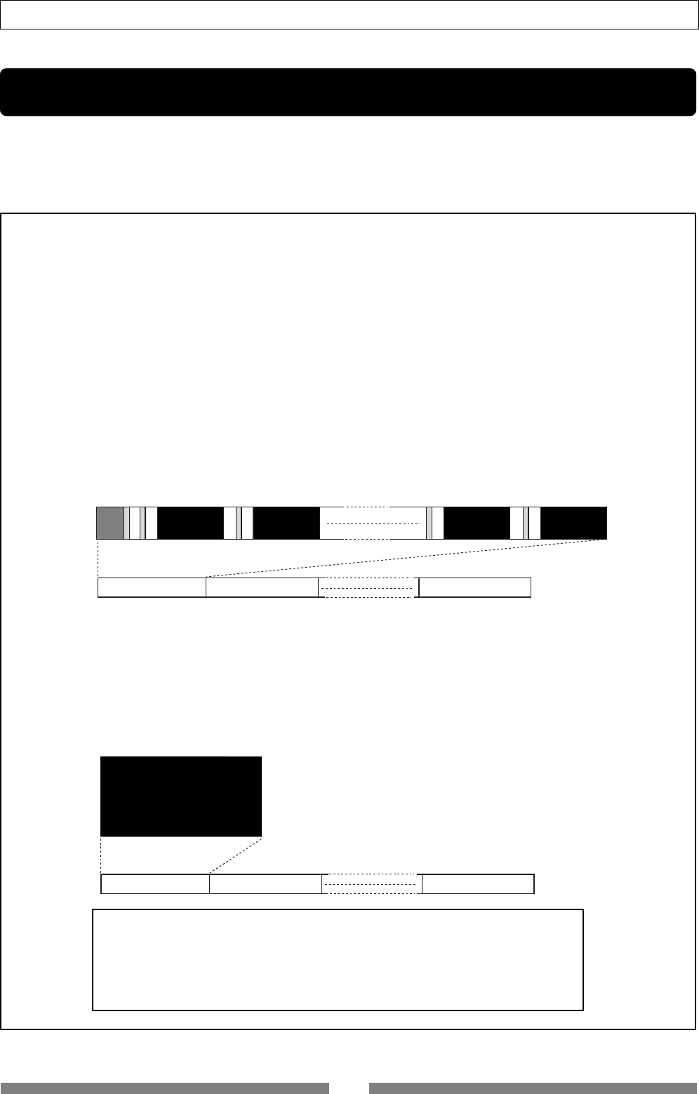
96
Save/Load of Song data
Trk 1&2 Trk 3&4 Trk 21&22 Trk 23&24
Program 1 (P01) Program 2 (P02) Program 99 (P99)
Trk 1 & 2 & 3 & 4 & 5 & 6 &7
& 8 & 9 & 10 & 11 & 12 & 13
& 14 & 15 & 16 & 17 & 18 &
19 & 20 & 21 & 23 & 24
Program 1 (P01) Program 2 (P02) Program 99 (P99)
Save/Load of song data
You can save or load song data (including audio and setup data) using a digital audio recorder via the S/P DIF
digital signal, as well as using a optional CD-RW drive (Model CD-1A).
This function allows you to save finished or unfinished song data to a digital recorder or a optional CD-RW
drive, and load the data later.
******About song data******
There are two methods of saving/loading song data depending on the digital signals used to handle the
data, which are S/PDIF digital and CD-RW drive. The data format and time required for the save/load
operations are different between each method.
•Using the S/PDIF digital signal (you can save/load data for each program individually.):
Following to five seconds of the pilot signal (shown in gray in the diagram below), the song data is output to an
external digital audio device such as a DAT recorder.
The audio data is divided into data blocks of track pairs (shown in black in the diagram below) and transferred.
To save data for Real tracks 1 through 8, 4 two-track data are transferred. To save all tracks including the Additional
tracks in addition to the Real tracks, 12 two-track data are transferred. Therefore, it will take about 4 times as much
as the recorded time of a program (from ABS 0 to REC END) to save the Real tracks 1 through 8 of the program, while
it will take about 12 times to save all the data including the Additional tracks.
When loading song data from the external device to the VF80 via the S/PDIF digital signal, data is transferred with
two-track data blocks, as with the same way as saving data from the VF80 to the external device. (See also <Notes>
on the next page.)
•Using a CD-RW/CD-R disc (you can save/load data for each program individually.):
See the following <Note>.
When using a CD-RW/CD-R discs, all audio data including both the Real and Additional tracks (shown in black in
the diagram below) is transferred simultaneously. Therefore, you can save or load a program much faster than
using the S/PDIF signal. Note that no pilot tone or beep sound is recorded when saving data to a CD-RW/CD-R discs.
If song data to be saved requires more space than the available disk space, you can save the data to more than one
disk (up to 99 disks). You can also save/load data by the WAV file format. In the save/load operation using the
WAV file, you can specify any track(s) to be saved or loaded, as well as all tracks.
<Note>
To save/load using a CD-RW/CD-R disc, you must install the optional CD-RW drive
in the VF80.
For the detailed information about the CD-RW drive, contact your dealer or the
nearest FOSTEX sales office. See 134 page about how to install the CD-RW drive in
the VF80.
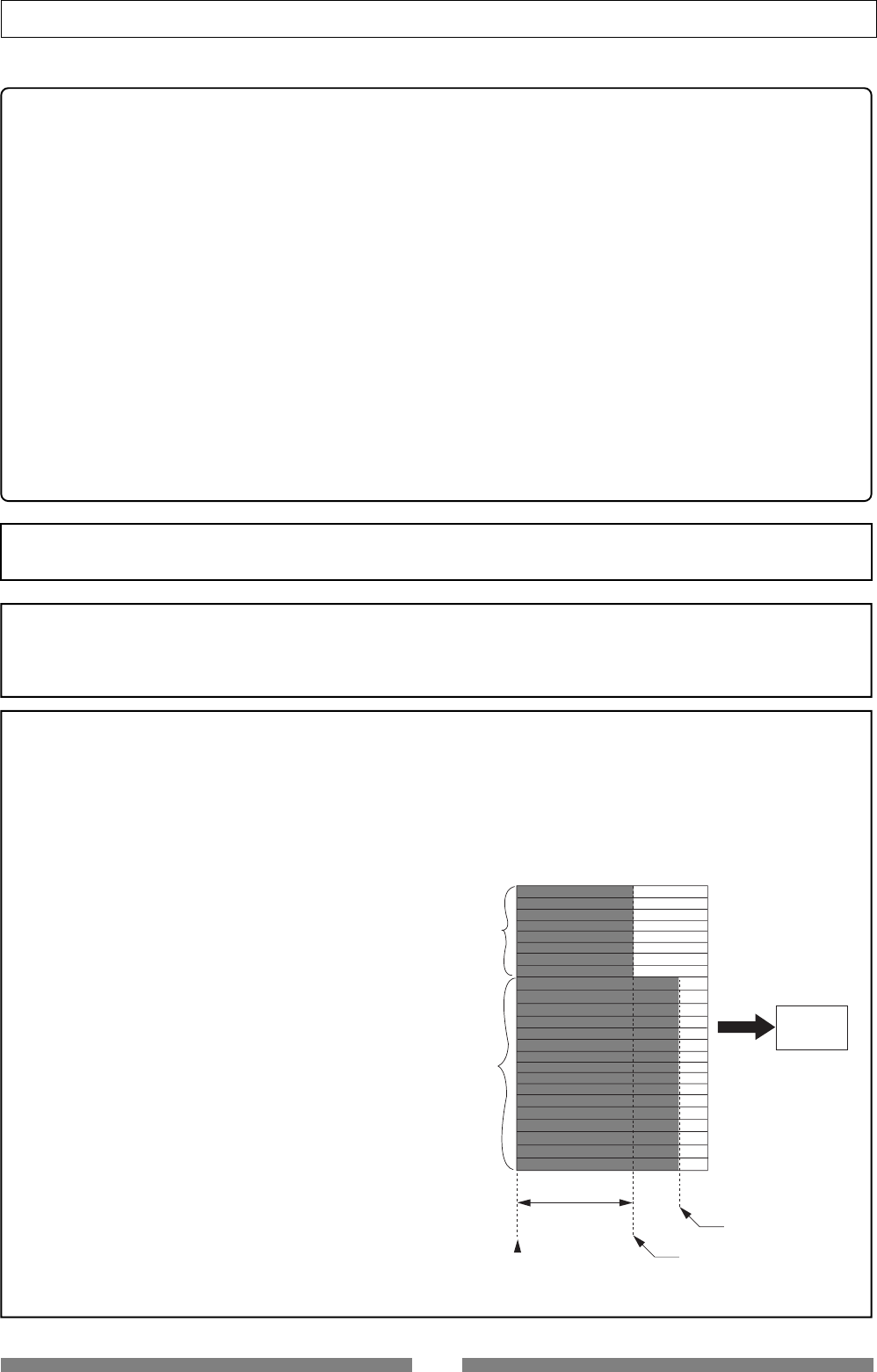
97
Save/Load of Song data
REC END (07m 00s)
of real track
REC END (10m 00s)
of additional track
seven minutes
Additional
Tracks
Real Tracks
DAT
Save
<Items that can be saved or loaded as song data>
•Memory data:
AUTO PUNCH IN/OUT data and Start/End/To points,
Scene memories 00 through 99, Marks 00 through 99 (only can be saved/loaded using CD-RW drive)
•Timebase:
ABS, MTC or BAR/BEAT/CLK
•Setup mode:
Bar/beat setting, tempo setting, metronome on/off, preroll time, MIDI synchronization output signal
setting, MTC offset time, MTC offset mode, REC protect setting, slave mode on/off, and slave type setting
Fader fix mode setting, fader recall mode setting
<Items that cannot be saved or loaded as song data>
•On/off settings for auto play mode and auto return mode
•Vari pitch on/off and pitch data
•Setup mode:
DIGITAL IN and DIGITAL OUT settings, bar/beat resolution on/off setting, device ID setting and drive
select setting
<Notes for digital audio recorders to be used>
The VF80 song data only can be saved to or loaded from digital recorders that can handle 16 bit, 44.1 kHz
linear digital data with S/PDIF format (such as DAT recorders).
<Notes for saving data using the S/PDIF digital signal>
When saving all data including both real and Additional track data using the S/PDIF digital signal, note the
following.
Only the data recorded within the time duration between ABS 0 and REC END of the Real tracks is saved.
Therefore, if the recorded time of Additional tracks is longer than the Real tracks, only the Additional track data
within the time duration between ABS 0 and REC END of the Real tracks is saved.
In the example shown on the right, the Additional
tracks have data from "00m 00s" to "10m 00s", while
the Real tracks have data from "00m 00s" to "07m 00s".
If you are going to save all tracks, the Additional track
data from "00m 00s" to "07m 00s" will be saved but
the rest will not be saved.
In such a case, you can solve the problem by setting
the time length of saved data to 10 minutes by using
the "Save Length" screen mentioned later (see "step
4" on page 99). Note that the maximum save length
is 59 minutes 59 seconds.
The other way to solve the problem is to exchange
the Additional track data and the Real track data
before saving data. You should be careful not to lose
the Additional track data in this operation. See page
68 about the "track exchange operation".
Saving/loading data using the S/PDIF digital signal
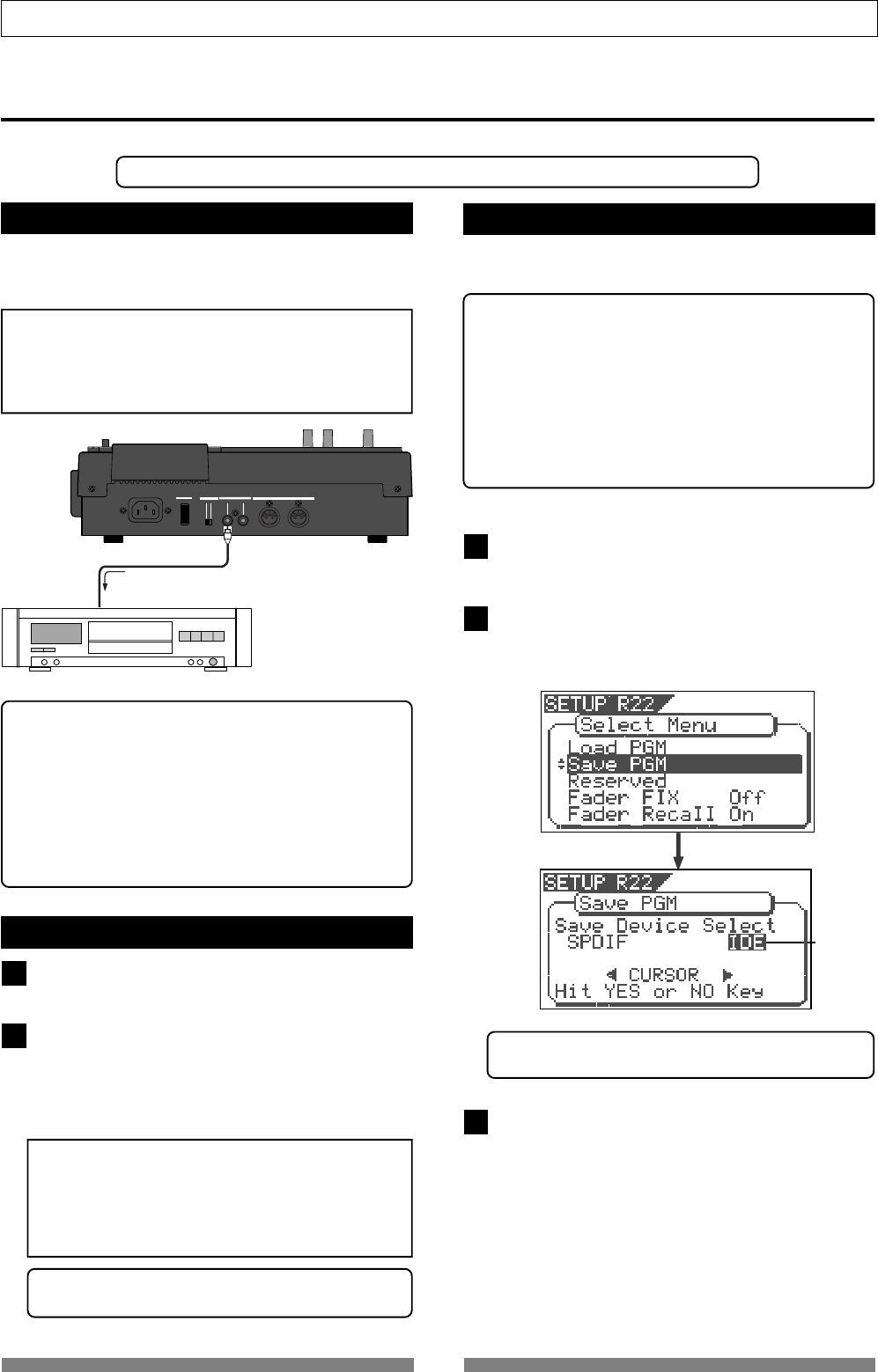
98
Save/Load of Song data
Digital equipment
Flashing
OFF
ON
MIDI
OUTPUT INPUT OUTPUT
INPUT
POWER PHANTOM S/P DIF / DATA
VF80
S/P DIF DATA OUTPUT
Saving data using the S/PDIF digital signal
You can save data using the S/PDIF digital signal via the [S/P DIF DATA OUTPUT] (coaxial) jack.
• Use an external digital recorder that supports 44.1 kHz sampling frequency (the same as the VF80,
Connecting to an external digital recorder
Connect the [S/P DIF DATA OUTPUT] jack to the digital
input jack of the external digital recorder (DAT, etc.).
<Note>
Do not do anything, such as unplug the connecting
cable, that interrupts the digital signal until the saving
operation is completed. Otherwise, the unit may
generates a noise which damages an external recorder.
• If your digital recorder only provide the optical digital
input jack and does not provide the coaxial jack, use
the optional COP-1 (optical/coaxial converter).
• Do not connect digital signals for both directions
between the VF80 and the external recorder (i.e. the
digital output of the VF80 to the digital input of the
external recorder and the digital output of the external
recorder to the digital input of the VF80), which may
form a digital loop and cause feedback.
Setting the external recorder
Set the sampling frequency to 44.1 kHz (the same as
the VF80).
Set the input source to "digital input" to accept the
signal from the VF80.
Some machine also needs to select the clock reference
to "external" when setting the input source to "digital
input". See the operation manual of the machine for
the detailed information.
<Note>
If you cannot hear the input signal or you hear
digital noise when monitoring the source signal of
the external digital recorder, check the connections,
cables and settings of both the VF80 and the external
recorder.
• See the operation manual of the external recorder for the
detailed information.
Saving data
You can save data via the "Save PGM" menu in the
setup mode.
<Details about "Save PGM" menu>
• Output signal options: S/PDIF and IDE (CD-1A)
• Program options: P01 to P99 (an individual Program)
• Track options:
* When using S/PDIF:
Tracks 1-8, Tracks 1-16, Tracks 1-24, Tracks 9-16, Tracks 9-24
or Tracks 17-24.
* When using IDE (CD-1A):
All tracks (1-24) is selected automatically. (You can select tracks
individually when saving by the WAV file format).
Press the [SETUP] key to enter the setup mode.
The display shows the screen for selecting the setup
menu.
Use the [JOG] dial to select "Save PGM" and press
the [ENTER/YES] key.
The display shows the screen for selecting the device
to which the data is saved. "IDE" flashes.
• "IDE" should be selected when saving or loading data via
CD-RW/CD-R.
Use the [JOG] dial or [CURSOR] keys to select
"SPDIF" and press the [ENTER/YES] key.
The display shows the screen for selecting the program
to be saved.
The program number currently selected flashes, while
the data size of the program is shown.
While a program number is flashing, you can select
the desired program to be saved.
1
2
2
1
3
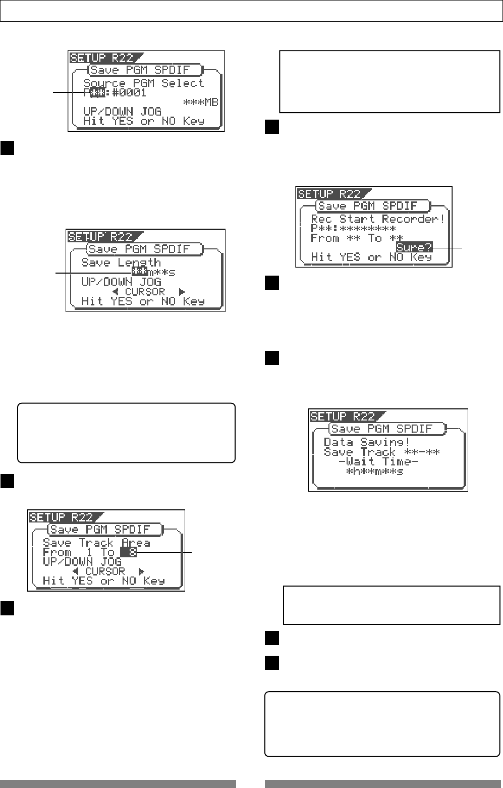
99
Save/Load of Song data
Flashing
Use the [JOG] dial to select the program to be saved
and press the [ENTER/YES] key.
The display shows the "Save Length" screen.
Initially, the recorded time length of the selected
program (ABS 00 to REC END) is shown as the time
length of data saving. Normally you do not need to
edit the length but you may edit it to the desired value
if needed.
Flashing
For example, if the actual recorded time is 9 min. 00
sec., you can make the length of the data to be saved
shorter or longer than 9 min. 00 sec., as long as the
length does not exceed 59 min.59 sec.
The initially displayed value here is the length of the
Real track, therefore, as noted earlier, you may edit
the value to match the length of the Additional track
if it is longer.
To edit the save length
Use the [CURSOR] keys to move the flashing field
between "minutes" and "seconds".
Use the [JOG] dial to set the value for the flashing
field.
Flashing
Press the [ENTER/YES] key.
The display shows the screen for selecting tracks to
be saved.
Select tracks to be saved.
Use the [CURSOR] keys to move the blinking field
between "From" and "To".
Use the [JOG] dial to set the track number for the
blinking field.
For the "From" field, you can select from 1, 9 and 17.
For the "To" field, you can select a higher value than
the "From" field value among 8, 16 and 24.
Accordingly, you can set "Save Track Area" to one of
the following.
"From 1 To 8", "From 1 to 16", "From 1 To 24", "From 9 To
16", "From 9 To 24", and "From 17 To 24"
<Note>
When you save tracks including Additional tracks,
read <Notes for saving data using the S/PDIF digital
signal> on page 97 before executing the save
operation.
After selecting tracks, press the [ENTER/YES] key
again.
The display shows "Rec Start Recorder!" together with
the program and tracks to be saved, and "Sure?"
flashes. If you are sure to start saving data to the
recorder, go on to the next step.
After checking all preparations on the external
recorder are made, start it recording.
It may be a good idea to put a Start-ID (for DAT) or
set a locate memory at the starting position so that
you can easily find the position when you load the
data later.
Press the [ENTER/YES] key immediately after the
external recorder starts recording.
The display shows something like the one below. After
a few seconds, the unit starts saving the data and "Wait
time" starts counting down.
For the first several seconds, the VF80 transmits the
pilot signal that will be a reference for locating the
tape position during the load operation, and the actual
data saving starts from the position at which "Wait
Time" starts counting down.
Data is saved in 2-track unit. When the data saving is
completed, "Completed!" appears on the screen and
the VF80 stops.
<Note>
If you interrupts saving before completing, the saved
data is invalid.
Stop the external recorder.
Press the [EXIT/NO] key (or the [STOP] key)
repeatedly until exiting the setup mode.
• To cancel each operation or to return to the previous
screen before pressing the [ENTER/YES] key, press the
[EXIT/NO] key (or the [STOP] key). Each press of the
key returns to the previous screen level and finally
exits the setup mode.
4
5
6
7
8
9
10
11
Flashing
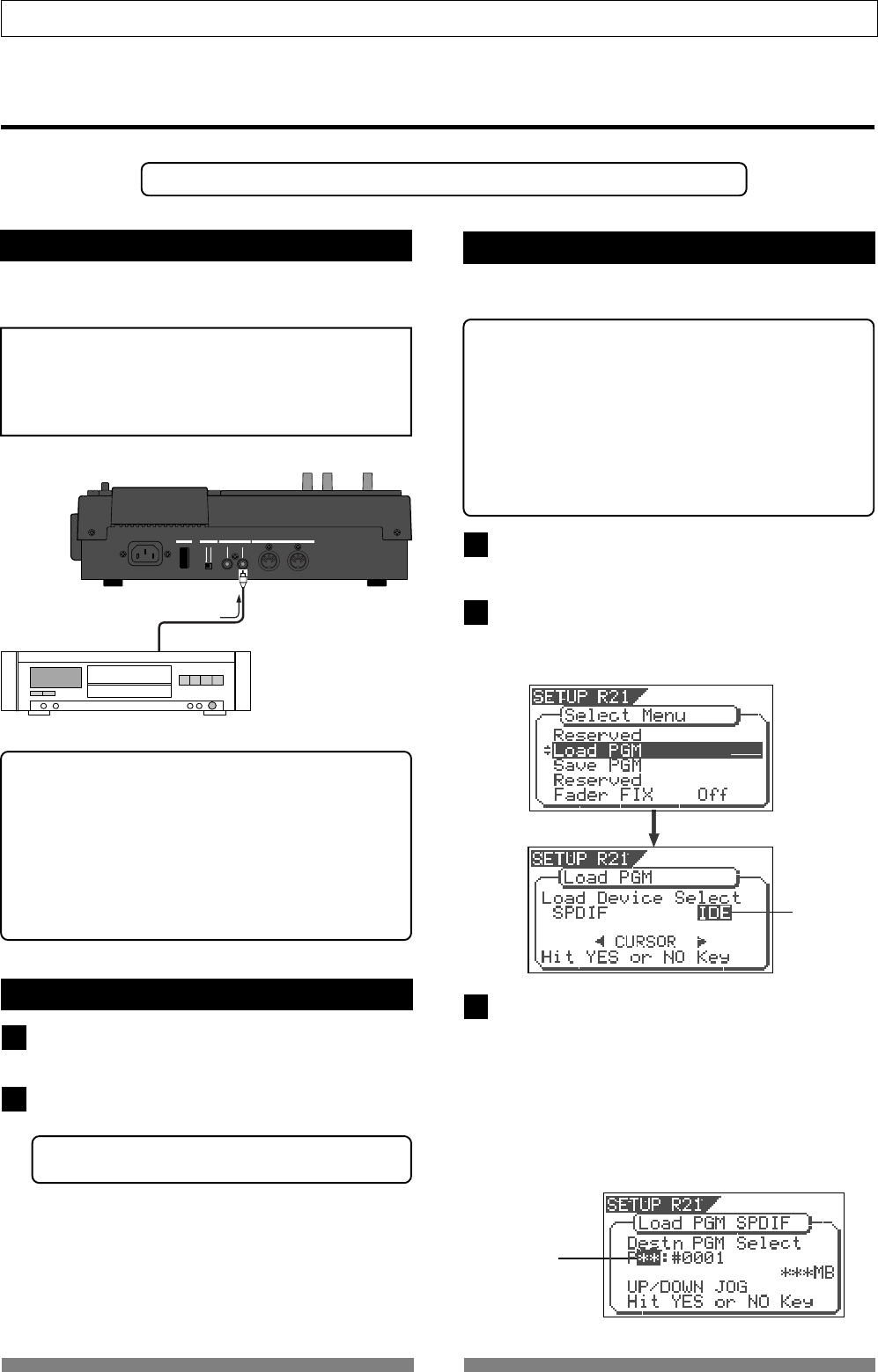
100
Save/Load of Song data
Flashing
OFF
ON
MIDI
OUTPUT INPUT OUTPUT
INPUT
POWER PHANTOM S/P DIF / DATA
Digital Equipment
VF80
S/P DIF DATA INPUT
Loading data using the S/PDIF signal
You can load data using the S/PDIF digital signal via the [S/P DIF DATA INPUT] (coaxial) jack.
*Use an external recorder that supports 44.1 kHz sampling frequency (the same as the VF80).
Connecting to an external recorder
Connect the [S/P DIF DATA INPUT] jack to the digital
output jack of the external digital recorder.
<Note>
Do not do anything, such as unplug the coaxial cable,
that interrupts the digital signal until the loading
operation is completed. Otherwise, the unit may
generates a noise which damages an external recorder.
• If your digital recorder only provide the optical digital
input jack and does not provide the coaxial jack, use
the optional COP-1 (optical/coaxial converter).
• Do not connect digital signals for both directions
between the VF80 and the external recorder (i.e. the
digital output of the VF80 to the digital input of the
external recorder and the digital output of the external
recorder to the digital input of the VF80), which may
form a digital loop and cause feedback.
Setting the external recorder
Make preparations of the external recorder for
outputting the digital signal.
Locate the beginning of the pilot signal for the song
data.
• See the operation manual of the external recorder for the
detailed information.
Loading data
<Details about "Load PGM" menu>
• Input signal options: S/PDIF and IDE (CD-1A)
• Program options: P01 to P99 (an individual Program)
• Track options:
* When using S/PDIF:
Tracks 1-8, Tracks 1-16, Tracks 1-24, Tracks 9-16, Tracks 9-24
or Tracks 17-24.
* When using IDE (CD-1A):
All tracks (1-24) is selected automatically. (You can select tracks
individually when saving by the WAV file format).
1
You can load data via the "Load PGM" menu in the
setup mode.
1
2
Press the SETUP key to enter the setup mode.
The display shows the screen for selecting the setup
menu.
Use the [JOG] dial to select "Load PGM" and press
the [ENTER/YES] key.
The display shows the screen for selecting the recorder
from which the data is loaded. "IDE" flashes.
2
Use the [JOG] dial or [CURSOR] keys to set "Load
Device Select" to "SPDIF" and press the [ENTER/YES]
key.
The display shows the screen for selecting a load
destination program to which data is loaded.
A program number currently selected blinks, followed
by its program name. The data size of the current
program is also shown. When a program number is
flashing, you can select the desired load destination
program.
Flashing
3
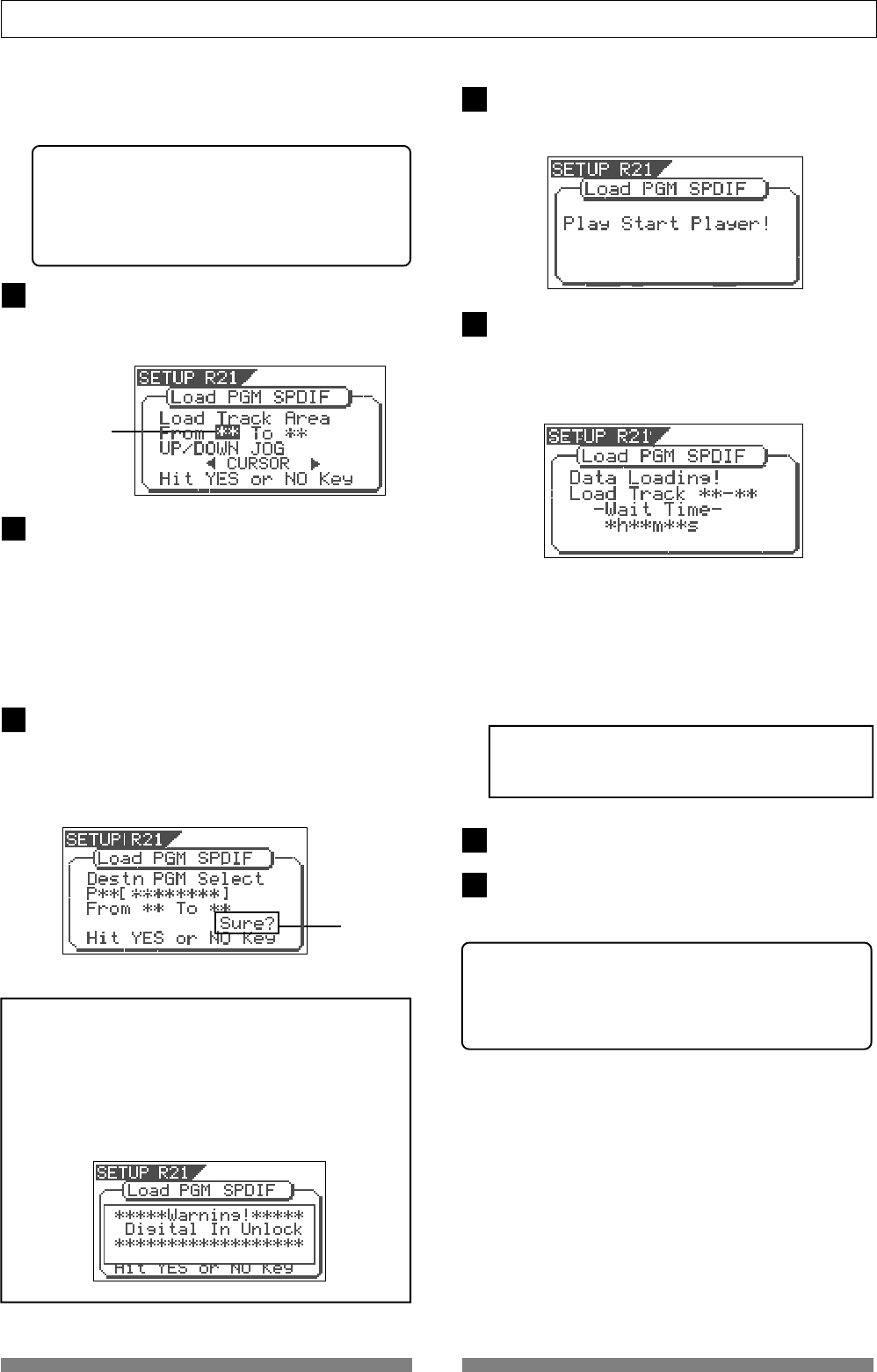
101
Save/Load of Song data
You can select a load destination program from existing
programs on the current drive as well as "New PGM".
When selecting "New PGM", a new program is created.
• If you load data to a program in which data is
already recorded, the newly loaded data
overwrites the current data track by track.
Consequently, on each overwritten track, the
loaded data becomes valid while the current data
is erased.
Use the [JOG] dial to select the program to which
data is loaded and press the [ENTER/YES] key.
The display shows the screen for selecting tracks to
be loaded.
Select tracks to be loaded.
Use the [CURSOR] keys to move the flashing field
between "From" and "To".
Use the [JOG] dial to set the track number for the
flashing field.
For the "From" field, you can select from 1, 9 and 17.
For the "To" field, you can select from 8, 16 and 24.
For example, if you select "From 1 to 24", data for all
tracks (1 to 24) will be loaded.
After selecting tracks, press the [ENTER/YES] key
again.
The display shows something like the one below. A
load destination program (existing or new program)
to which the data is loaded and tracks to be loaded
are shown, while "Sure?" flashes.
<Note>
In the above step, if the VF80 does not lock to the
digital signal from the external digital recorder, the
following warning message appears on the display,
showing that the VF80 does not receive a correct S/
PDIF digital signal. So check the cable connection and
the digital output setting of the external digital
recorder.
When the VF80 is locking to the digital input signal,
press the [ENTER/YES] key.
The display shows "Play Start Player!".
Start playback of the external recorder.
After reading the pilot signal recorded when saving
the data, the data starts loading automatically.
When starts loading, the display shows something like
the one below, in which "Wait time" starts counting
down.
Data is loaded in 2-track unit.
While loading, the [TRACK STATUS/TRACK SEL] keys
for channels 1 and 2 flash, while the input levels are
displayed by level meters 1 and 2.
When the data loading is completed, "Completed!"
appears on the screen.
<Note>
If you quit loading before completing, the loaded
data is invalid.
Stop the external recorder.
Press the [EXIT/NO] key (or the [STOP] key)
repeatedly until exiting the setup mode.
• To cancel each operation or to return to the previous
screen before pressing the [ENTER/YES] key, press the
[EXIT/NO] key (or the [STOP] key). Each press of the
key returns to the previous screen level and finally
exits the setup mode.
4
5
6
7
8
9
10
Flashing
Flashing
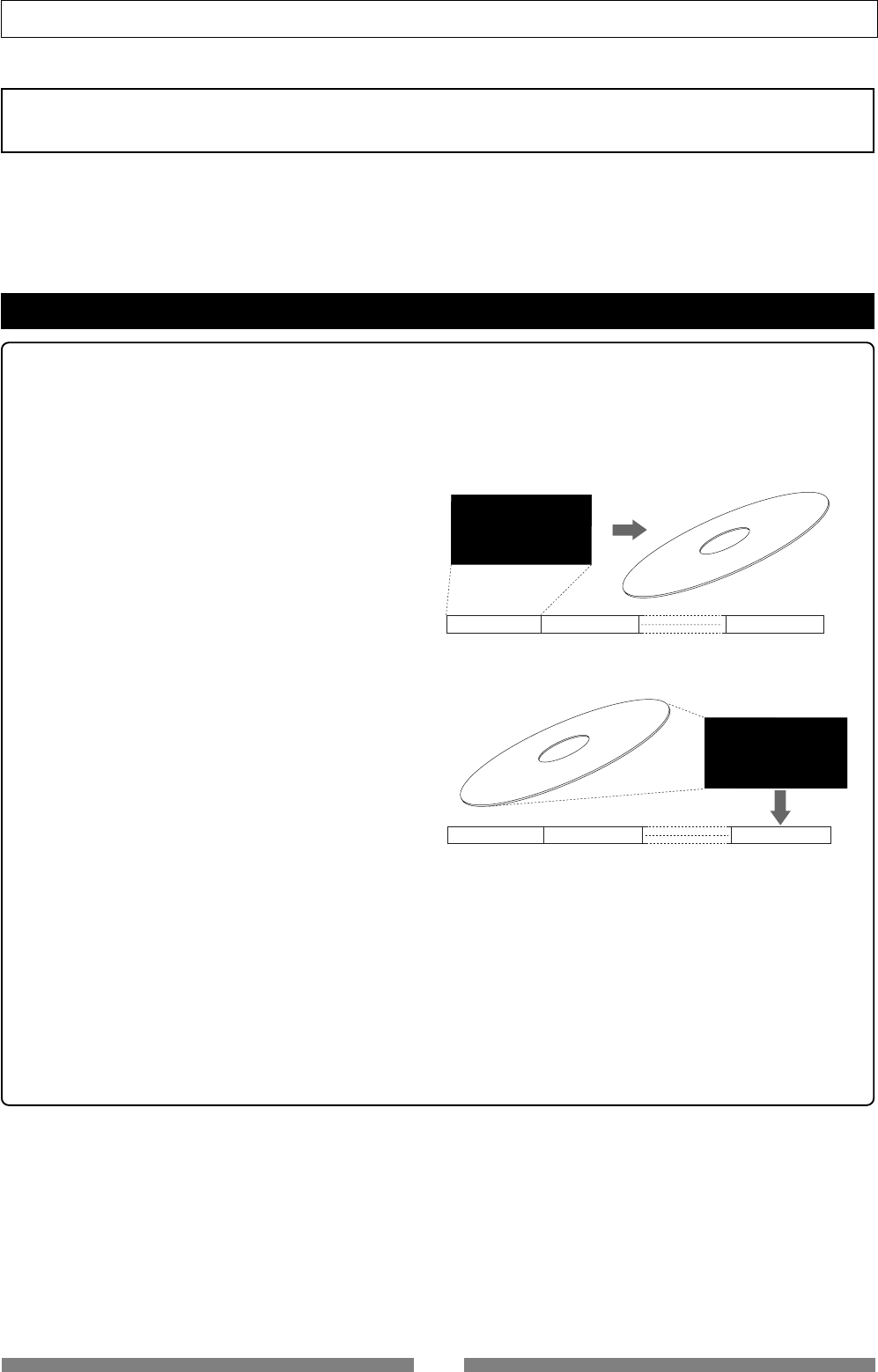
102
Save/Load of Song data
Please read this first!
Save/Load using CD-RW/CD-R
By installing the optional CD-RW drive (Model CD-1A) to the VF80, you can save or load data in the
FDMS-3 or WAV file format using a CD-RW/CD-R disc. In addition, you can create an audio CD (CD-
DA) or load audio data from an audio CD.
Please read the notes below first before performing the save/load operation.
Save/load of Song Data Using a CD-RW drive
The save/load operation using a CD-RW/CD-R disk is performed in the following manners.
• Save
You can only a single selected program data to a
disc regardless of the program data amount.
You cannot save more than one program data even
if there are enough disc space.
However, you can save a program data to more
than one disc if the data amount is larger than a
disc space.
As shown on the right, you can save almost all
necessary information such as song data of all
tracks (real and additional tracks) and mixer scene
data.
• Load
The data loading using a CD-RW drive is taken
place after a “new program” is created in the cur-
rent drive (the load destination).
You cannot overwrite an existing program with
the loaded data.
The newly created program is numbered the next
number to the highest existing program number.
• Creating an audio CD
You can make an audio CD by recording sound data of tracks 1 and 2 between the “Start point” and “End
point” to a CD-RW/CD-R disc. It is also possible to record some mastered materials continuously.
• Loading an audio CD data
You can load a material on a (commercial or created) audio CD to a program of the VF80.
Audio data is loaded to a “new program” automatically created by the VF80, which is the same way as
backup data loading. The VF80 never overwrites the existing program.
Trk 1 & 2 & 3 & 4 & 5 & 6 &7
& 8 & 9 & 10 & 11 & 12 & 13
& 14 & 15 & 16 & 17 & 18 &
19 & 20 & 21 & 23 & 24
Program 1 (P01) Program 2 (P02) Program 99 (P01)
Save
Current drive of the VF80
Trk 1 & 2 & 3 & 4 & 5 & 6 &7
& 8 & 9 & 10 & 11 & 12 & 13
& 14 & 15 & 16 & 17 & 18 &
19 & 20 & 21 & 23 & 24
Program 1 (P01) Program 2 (P02) New Program
Load
Current drive of the VF80
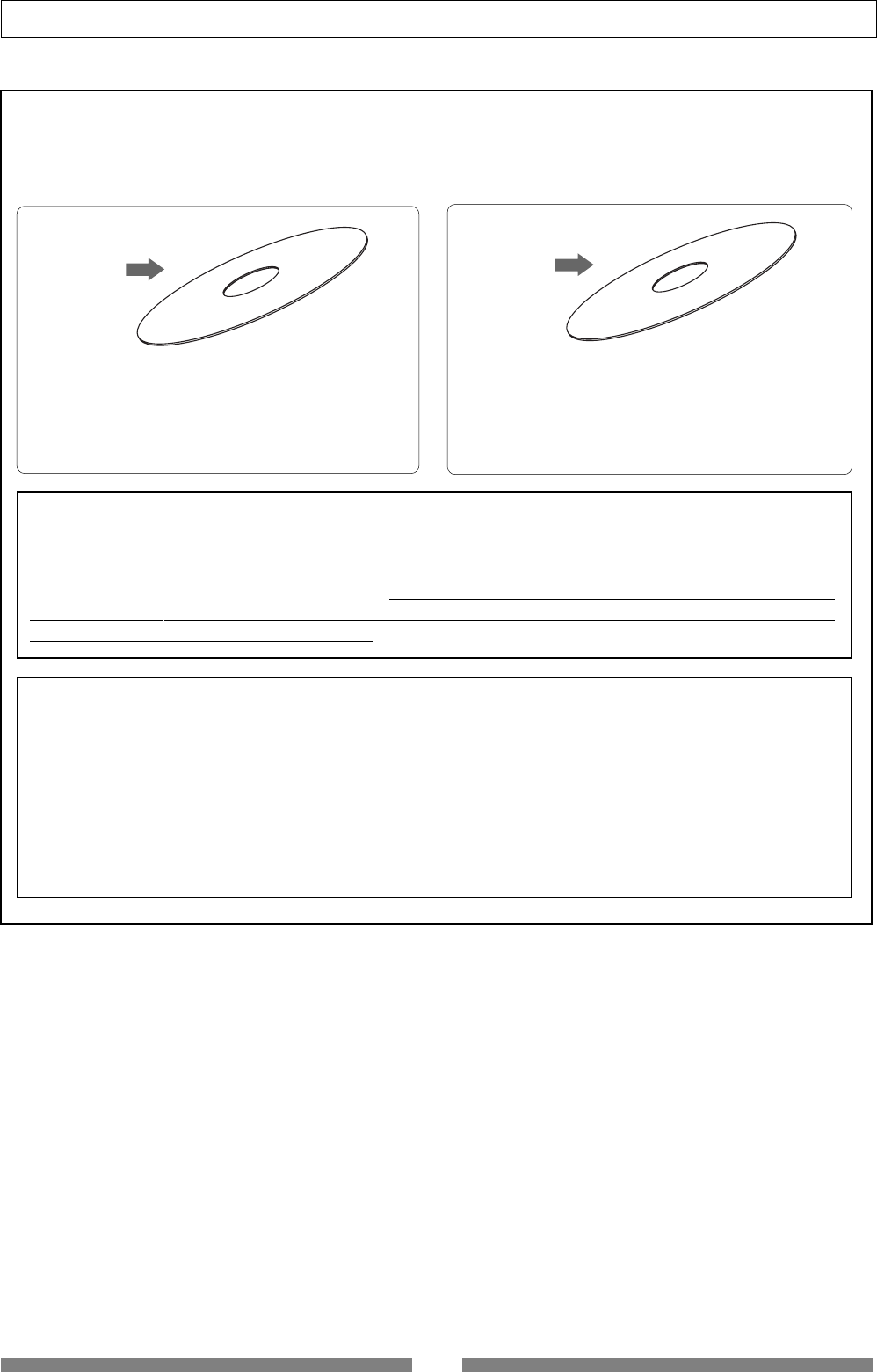
103
Save/Load of Song data
With an optional CD-RW drive, you can use not only CD-RW discs but also CD-R discs. Note that
CD-R discs has some restrictions as shown below.
<Care and handling of CD-RW/CD-R discs>
<About data writing and reading speeds for data save/load>
The writing and reading speeds for data save and load of the VF80 are automatically set as below.
• Writing speed: according to a CD-RW drive used, however the maximum speed is 8 times.
• Reading speed: according to a CD-RW drive used.
The writing speed depends on a CD-RW drive but it is limited to 8 times.
For save/load of the VF80 data, use discs that can be written at 4 times or higher speed. Do not use
discs that only can be written at real-time or twice speed.
<Note>
A CD-RW/CD-R disc on which VF80 data is recorded can only be played by Fostex machines. Do not
play it by non-Fostex devices. The drive or system used may be damaged.
However, a CD-RW/CD-R disc with audio CD format created by the Fostex machine can be played by
general machines such as audio CD players.
(If an audio CD is made using a CD-RW disc, it can be played
back only by a player that supports CD-RW playback. You cannot playback such a disc by a conventional CD
player that does not support CD-RW playback.)
You can save (record) data to a disc as many times
required. Note that when saving new data, it is recorded
after the previously recorded data is erased. In other
words, every time you save new data, all disc data is
rewritten. (See “Saving data” described later.)
You can save (record) data to a disc only once.
You cannot save data to a recorded disc. You can, of
course, load data as many times as required.
CD-RW disc
CD-R disc
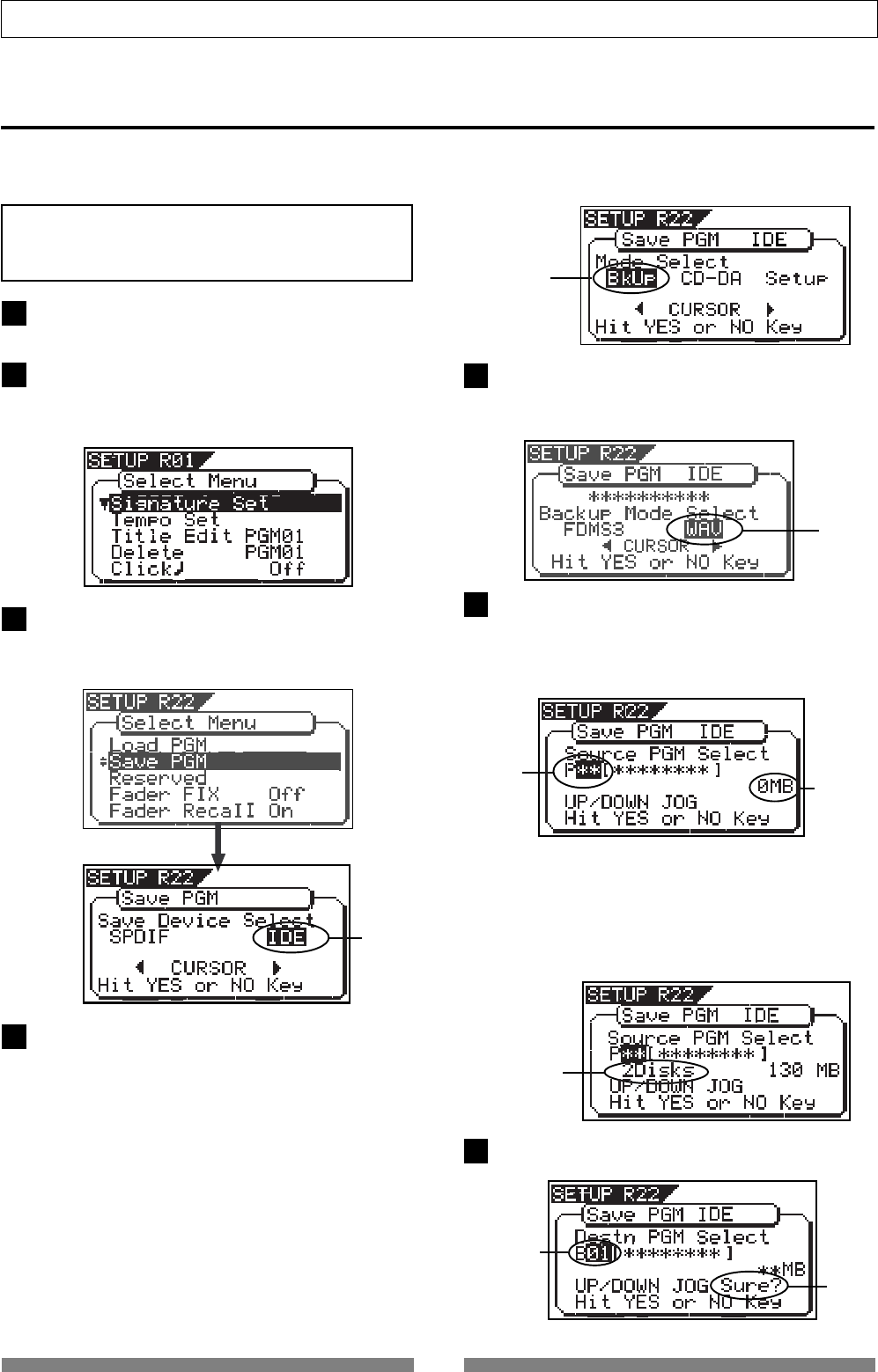
104
Save/Load of Song data
After turning on the VF80, insert a disc to the CD-RW
drive.
Press the [SETUP] key of the VF80 to enter the setup
mode.
The display shows the screen for selecting the setup
menu.
The following procedure describes how to save FDMS-3 song data.
We assume that the optional CD-RW drive (Model CD-1A) is already installed to the VF80 and a virgin CD-RW
or CD-R disc is set.
Use the [JOG] dial to select (highlight) “Save PGM”
and press the [ENTER/YES] key.
The display shows the screen for selecting a save de-
vice, where “IDE” is flashing.
After selecting a program, press the [ENTER/YES] key.
The display shows the screen as below.
<Note>
Do not carry out any VF80 key operation until the ac-
cess process to the CD-RW/CD-R disc is completed.
Flashing
Saving data using a CD-RW drive (Backup)
By rotating the [JOG] dial, you can select a desired
program number/title from among available programs
in the VF80 current drive. The recorded space of the
selected program is also shown.
If you select a program which requires more than one
disc for saving, the display shows the required num-
ber of discs (see the screen example below).
Use the [CURSOR <] key to select (highlight) “FDMS3”
and press the [ENTER/YES] key.
The display shows the screen for selecting a program
to be saved (the program number of the selected pro-
gram flashes).
flashing
Flashing recorded
space
number of
discs
Flashing
1
2
3
4
6
7
While “IDE” is flashing, press the [ENTER/YES] key.
After briefly showing the model name of the connected
CD-RW drive, the display shows the screen for select-
ing a save mode, where “BkUp” (backup) is flashing.
To save (backup) song data, select “BkUp”.
To make an audio CD, select “CD-DA” or “Setup”.
This procedure describes how to save song data, so
we select “BkUp” here.
See “making an audio CD” described later for details
about how to make an audio CD.
While “BkUp” flashing, press the [ENTER/YES] key.
The display shows the screen for selecting a backup
mode (between FDMS-3 and WAV), where “WAV” is
flashing.
5
flashing
flashing
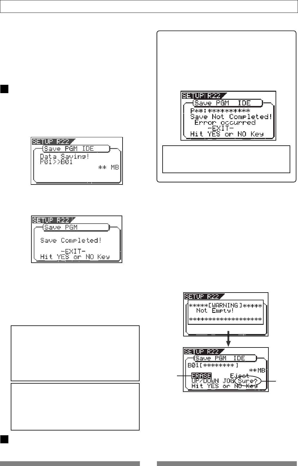
105
Save/Load of Song data
<About save error>
If an error occurs for some reason during the save
operation, the error message as below appears.
If it appears, press the [EXIT/NO] key.
The display returns to the previous screen before
performing the save operation.
Note that saved data before the error message ap-
pears is all invalid.
<Note for saving data to more than one disc>
If you save data to more than one disc, we rec-
ommend to put a number on each disc in the
saving order (such as DISC-1, DISC-2, etc.) so
that you will easily know the order for inserting
discs when loading data.
<Hint 1>
In the description for saving data above, we assume
to use a non-recorded CD-RW/CD-R disc.
If you use a recorded disc (including a disc on which
computer data is recorded), also note the following.
By performing step 5 in the save operation proce-
dure shown above (“While “BkUp” is flashing, press
the [ENTER/YES] key”.) When a recorded disc is in-
serted, the display shows a warning message, fol-
lowed by the confirmation screen (where “Sure?”
flashes).
With this screen, you can choose whether erasing
the recorded data or ejecting the disc.
• To erase the existing (recorded) data
Press the [ENTER/YES] key while both “ERASE” and
“Sure?” are flashing.
The display shows the screen below and the VF80
starts erasing the disc.
As the erase process progresses, the number of
flashing “ * ” increases from left to right.
<Note>
You cannot abort the save operation before com-
pleted. Especially during the save operation to
more than one disc, if you happen to press the
[EXIT/NO]
key while removing or inserting a disc,
you have to redo the save operation from the
beginning with the first disc.
<Note>
If the message above appears while saving data
to a CD-R disc, you can no longer use the disc.
Press the [EXIT/NO] key (or the [STOP] key) to exit
the Setup mode.
When saving data to more than one disc, the first disc
will be ejected when it is full (i.e. there is no more
recording space on the disc), while “Insert Disk!” ap-
pears on the screen.
After inserting the second disc, the VF80 automati-
cally resumes the save operation.
After completing the save operation, the final disc is
ejected and the above screen appears. (See <Note> be-
low).
Flashing Flashing
When completing the save operation, “Save Com-
pleted!” appears on the display (as shown below) and
the VF80 stops access to the drive, while the disc in
the CD-RW drive is automatically ejected.
While “B01” is shown, press the [ENTER/YES] key.
The VF80 starts the save operation.
The recorded space shown on the display is counted
down while the save operation progresses.
It will take some time for saving all data. The follow-
ing display example shows that the data of the se-
lected program number is being saved to the backup
number “B01”.
8
9
In the example above, the selected program data will
be saved to a CD-RW/CD-R disc with the backup num-
ber “B01”. The program title is copied to the backup
title (you can not edit it).
By rotating the [JOG] dial when the above screen is
shown, you can also select “Eject”, besides “B01”.
If you select “Eject” and then press the [ENTER/YES]
key, the disc will be ejected.
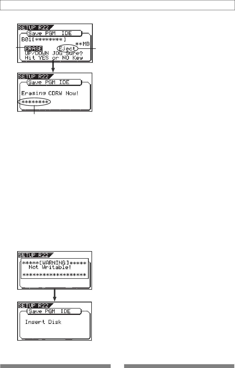
106
Save/Load of Song data
Immediately after completing erasing the disc, the
display shows the same screen (for selecting a pro-
gram to be saved) which appears after step 5 is
performed. Hereafter, perform the same proce-
dure as described above.
Flashing Flashing
Increases as the process progresses.
<Hint 2>
If you try to save data to a recorded CD-R disc, the
display shows a warning message saying “Not Writ-
able”, followed by a message saying “Insert Disk” as
below.
• To eject the disc
Use the [JOG] dial to highlight “Eject” (flashing)
and press the [ENTER/YES] key.
The disc is ejected while the display shows “Insert
Disk!”.
By inserting a disc, you can start the save opera-
tion again from the beginning.
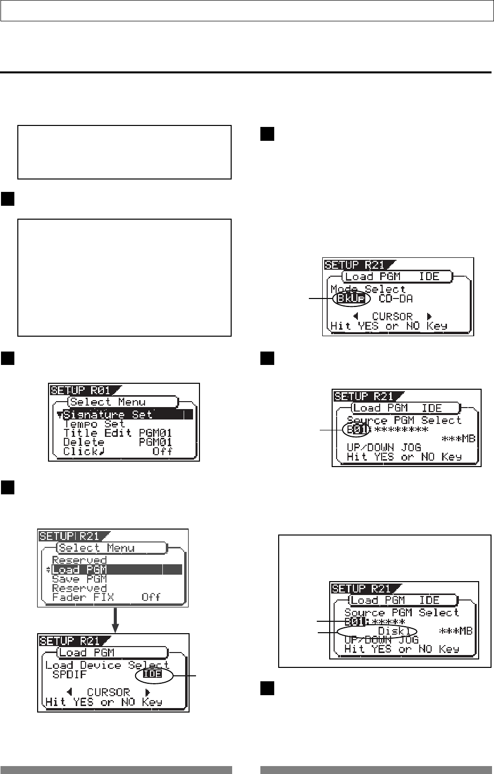
107
Save/Load of Song data
Press the [SETUP] key to enter the setup mode.
The display shows the screen for selecting the setup
menu.
Use the [JOG] dial to select (highlight) “Load PGM”
and press the [ENTER/YES] key.
The display shows the screen for selecting a load de-
vice, where “IDE” is flashing.
Loading backup data from a CD-RW drive
<Note>
Do not carry out any VF80 key operation until
the access process to the CD-RW/CD-R disc is
completed.
<Note>
If you load song data which is saved to more
than one disc, set DISC-1 first.
If you set the other disc and go on the follow-
ing procedure, the VF80 automatically recog-
nized that the disc order i s not correct and
the display shows
“Wrong Disk”
, followed by
“Illegal No!”
momentarily, and the disc is au-
tomatically ejected.
After turning on both the VF80, insert the disc to the
CD-RW drive.
While the desired backup number/title is shown on
the display, press the [ENTER/YES] key.
The display shows the screen for creating a new pro-
gram on the current drive, to which data will be loaded
(“New PGM” lights).
When you load song data which is saved to more
than one disc, the display also shows the disc num-
ber currently set. The example below shows DISC-
1 is set.
By rotating the [JOG] dial, you can select a desired
program number/title from among available programs
in the VF80 current drive. You can also select “Eject”.
If you select “Eject” and press the [ENTER/YES] key,
the disc is ejected
Flashing
Flashing
Light up
The following procedure describes how to load FDMS-3 song data.
We assume that the optional CD-RW drive (Model CD-1A) is already installed to the VF80 and a CD-RW or CD-
R disc on which the song data is recorded is set.
While “IDE” is flashing, press the [ENTER/YES] key.
After briefly showing the model name of the connected
CD-RW drive, the display shows the screen for select-
ing a load mode, where “BkUp” (backup) is flashing.
To load song data saved, select “BkUp”.
To load a material from an audio CD, select “CD-DA”.
This procedure describes how to load song data, so
we select “BkUp” here.
See “Loading from an audio CD” described later for de-
tails about how to load a material from an audio CD.
Flashing
While “BkUp” is flashing, press the [ENTER/YES] key.
The display shows the backup number and title, as
well as recorded space.
Flashing
1
2
3
4
5
6
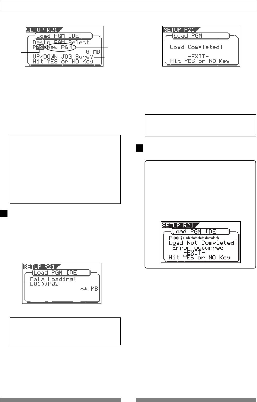
108
Save/Load of Song data
When completing the load operation, “Load Com-
pleted!” appears on the display (as shown below) and
the VF80 stops access to the drive, while the disc in
the CD-RW drive is automatically ejected.
As described earlier, when loading data from a CD-
RW drive, the VF80 creates a new program on the
current drive, which is the load destination.
Therefore, “New PGM” is shown on the right of the
flashing program number.
The program number for the newly created destina-
tion program is the next number to the highest exist-
ing program number.
For example, if there are 8 existing programs (“P01”
through “P08”) on the current drive, the newly cre-
ated program is numbered “P09”.
Press the [EXIT/NO] key (or the [STOP] key) to exit
the setup mode.
<Note>
If you rotate the
[JOG]
dial while the above screen
(
“Destn PGM Select”
) is shown, you can select an
existing program on the current drive as the desti-
nation. However, as mentioned earlier, when load-
ing data using CD-RW you cannot actually load
data to the existing program by overwriting the
program data.
If you press the
[ENTER/YES]
key (see the next step)
while selecting an existing program as the destina-
tion, the display shows
“Void!”
and the VF80 ig-
nores the operation.
While “New PGM” is shown, press the [ENTER/YES]
key.
The VF80 starts the load operation.
The recorded space shown on the display is counted
down while the load operation progresses.
It will take some time for loading all data.
The following display example shows that the data of
the backup number “B01” is being loaded to “P08”
which is newly created on the current drive.
<Note>
If there is not enough available space for loading
on the current drive, the display shows
“Disk Full!”
and the display returns to the previous screen.
<Note>
You cannot abort the load operation before com-
pleted.
When loading data from more than one disc, the first
disc will be ejected immediately after all disc data has
been loaded, while “Insert Disk!” appears on the screen.
After inserting the second disc, the VF80 automati-
cally resumes the load operation.
After completing loading all the discs, the above screen
appears.
<About load error>
If an error occur for some reason during the
load operation, the error message as below ap-
pears.
If it appears, press the [EXIT/NO] key.
The display returns to the previous screen be-
fore performing the load operation.
Note that loaded data before the error message
appears is all invalid.
<Display example for loading>
Flashing
Light up
7
8
Flashing
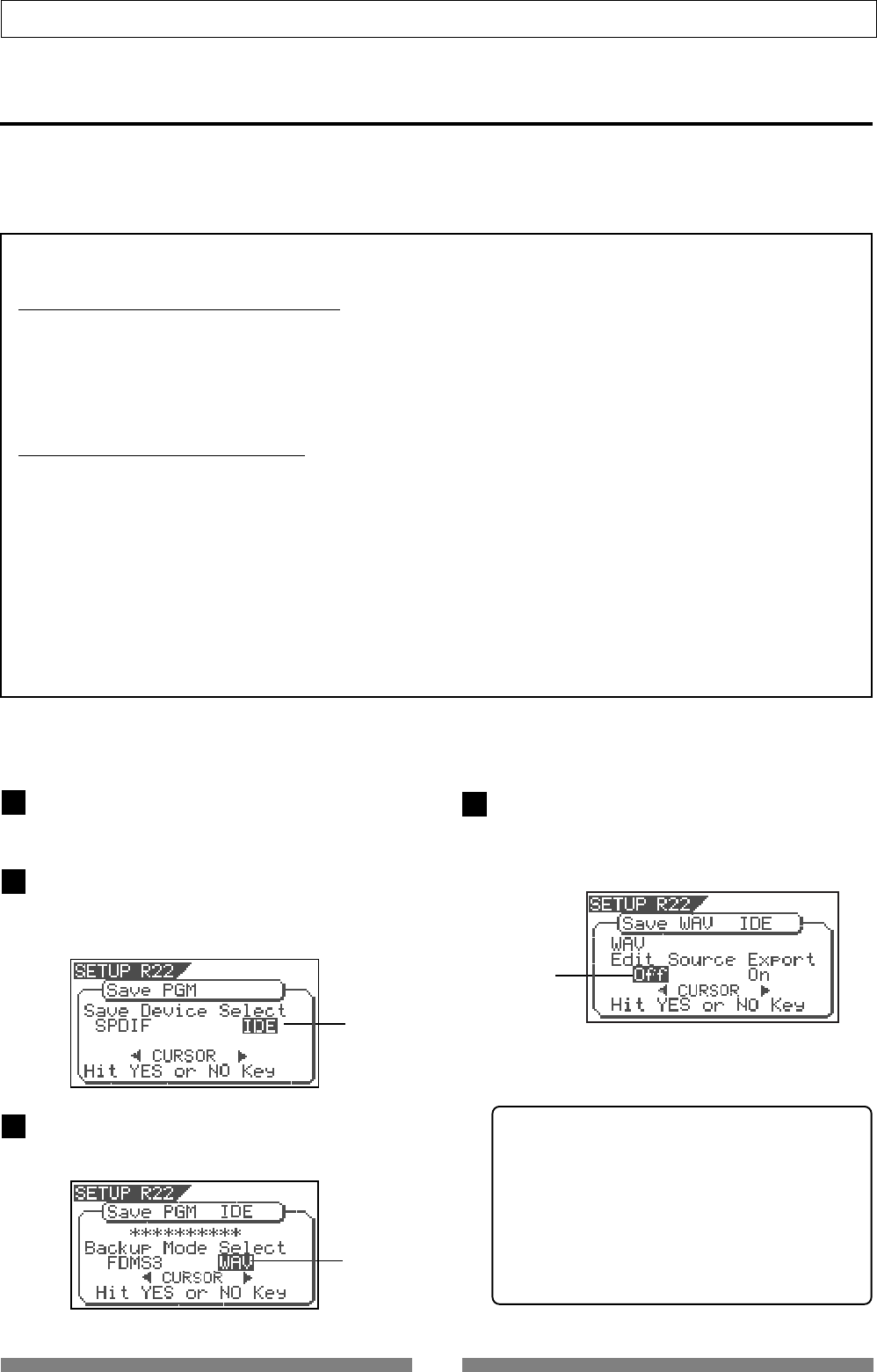
109
Save/Load of Song data
Saving a WAV file
Song data can be saved to or load from a CD-R/CD-RW disc by the FDMS-3 (Fostex Disk Management System-
3) format, as well as by the WAV file format. As you can handle song data of the VF80 with a WAV file, it is
possible to directly import/export data from/to a personal computer, to playback/edit a data file with various
software applications, and to import a data file edited by a computer to the VF80.
<Important notes for using a WAV file>
About directory of a backup disk:
• A WAV file saved is recorded in the root directory (in the first layer) on the backup disk.
• A WAV file that can be loaded must be allocated in the root directory on the backup disk.
A WAV file moved from the root directory to another area such as a folder cannot be recognized by the
VF80, which may cause a malfunction.
About file names of WAV files
• A WAV file the VF80 saves is recorded with a file name "******##.WAV".
• A WAV file the VF80 can load must have a file name "******##.WAV".
The first 6 characters "******" are the title that is shown in the "Title Edit" screen in the setup mode.
These characters can be changed when saving using a WAV file or edited by a computer.
The following 2 characters "##" indicate the track number (1 to 24) for the save/load using a WAV file.
The last ". WAV" is the file extension indicating that the file format is WAV.
The VF80 does not recognize other file names than above. See the following description for each
operation about details.
By using the specifications above, you can load only the desired tracks of a WAV file or load a track-
swapped WAV file. See "Loading a WAV file" described later for details.
You can save a WAV file. The following procedure assumes that the newly CD-RW/CD-R disk is used for
backup.
4
Flashing
Flashing
Flashing
Press the [SETUP] key to enter the setup mode.
The display shows the screen for selecting the Setup
menu.
Use the [JOG] dial to select "Save PGM" and press
the [ENTER/YES] key.
The display shows the screen for selecting the device
to which the data is saved. "IDE" flashes.
While "IDE" is flashing, press the [ENTER/YES] key.
The display shows the screen for selecting the backup
mode (FDMS 3 or WAV), where "WAV" flashes.
While "WAV" is flashing, press the [ENTER/YES] key.
The display shows the screen for selecting On or Off
of the Edit Source Export function, where "Off" flashes.
You can switches between On and Off by using the
[CURSOR] keys .
If you save all data from "ABS 0" to "REC END" (in
most cases), you do not have to change the setting
here.
3
2
1
<About the Edit Source Export function>
The Edit Source Export function allows you to save
the desired range of data between the Start and
End points which are set when executing the Copy-
paste or Move-paste function.
Therefore, if you want to save only the specific range
of data, you have to register the Start and End points
before the save operation.
See "Track Editing" in "Recorder Function" for
details about how to set the Start and End points.
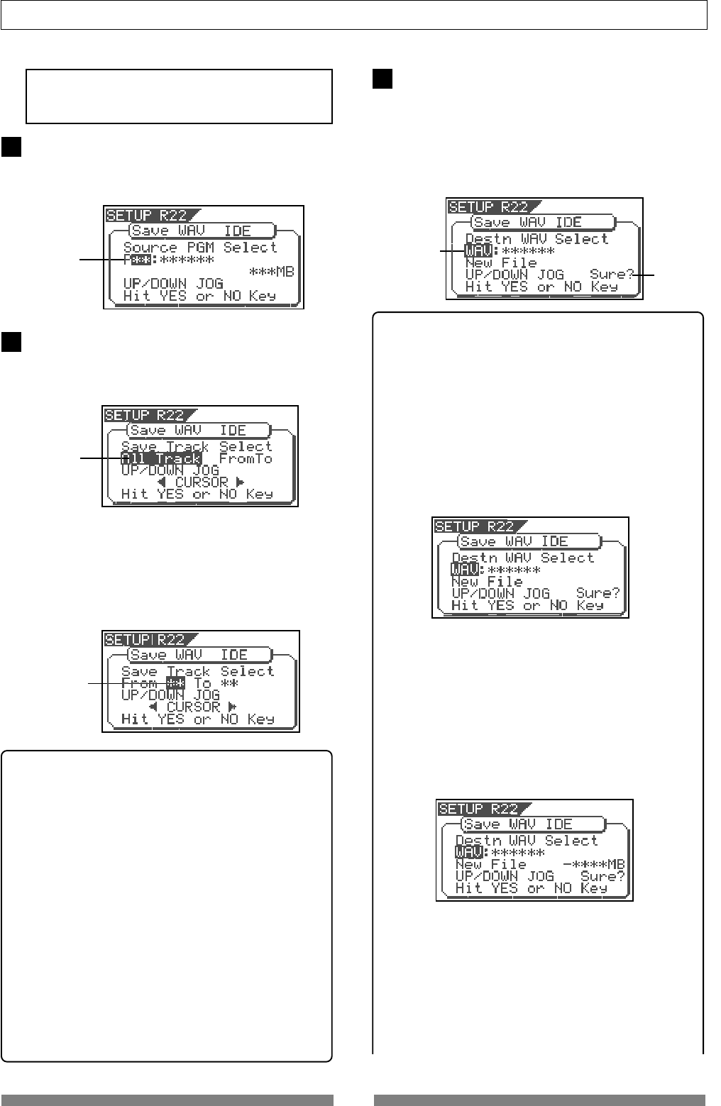
110
Save/Load of Song data
Flashing
7After selecting the track(s), press the [ENTER/YES]
key.
The display shows the screen for selecting a WAV file
on the disk.
If no file is recorded on the disk, "WAV" and "Sure?"
flashes. You can select "Eject" by rotating the [JOG]
dial. To remove the disk, select "Eject" and press the
[ENTER/YES] key.
<Hints>
If the backup disk contains any existing program(s)
previously saved, the display may show following
screens after carrying out the previous step, depending
on the available space of the backup disk.
•Showing the title and "New File":
There is enough space for creating a new WAV file in
addition to the existing WAV files on the disk.
Pressing the [ENTER/YES] key advances to the next step
(for editing the file name).
After completing the save operation, this new WAV file
will be added on the disk.
•Showing the title and "New File", and "-****MB"
alternately:
The space for adding a new WAV file to the existing
WAV files on the disk is ****MB short.
Pressing the [ENTER/YES] key shows "Disk Full!",
followed by "Delete All WAV?".
Pressing the [ENTER/YES] key again deletes all the WAV
file on the disk and advances to the next step (for
editing the file name)
After completing the save operation, only this new WAV
file will remain on the disk.
•Showing the title and "****MB":
To get enough space for creating a WAV file, the
specified file on the backup disk will be deleted.
By pressing the [ENTER/YES] key, "DEL" appears.
Pressing the [ENTER/YES] key again will delete the
specified WAV file on the disk and advances to the
next step (for editing the file name).
After completing the save operation, the specified WAV
file will be replaced with the new WAV file on the disk.
Flashing
Flashing
Flashing
While "Off" is blinking, press the [ENTER/YES] key.
The display shows the screen for selecting a program
to be saved. The program number currently selected
flashes, while the data size of the program is shown.
Use the [JOG] dial to select a program to be saved
and press the [ENTER/YES] key.
The display shows the screen for selecting a track to
be saved. Initially, "All Track" flashes.
By rotating the [JOG] dial (or press the [CURSOR] </>
key), you can select "From ** To **" (where the left field
flashes initially) instead of "All Track".
If you save data for all tracks (1 through 24), select
"All Track". If you save data for any specific track(s),
select "From ** To **" and specify the desired track
numbers.
<To specify the desired tracks to "From ** To **">
By rotating the [JOG] dial while the left ("From") field
is flashing, you can select the track number from 01
through 24. The number in the right ("To") field
automatically follows the number in the left field (i.e.
numbers in the left and right fields are always the same).
Therefore, if you want to save a single track, you just
have to set the right ("From") field and do not have to
set the right ("To") field. For example, "From 02 To 02"
will save only track 2.
To specify tracks 5 through 12:
•Enter "05" to the left field while the left field is
flashing.
•Press the [CURSOR </>] key to make the right field
flashing.
•Enter "12". (Note that the number for the right field
must be equal to or larger than the left field.)
Finally the screen shows "From 05 to 12" to save tracks
5 through 12.
5
6
<Note>
If you save all data from "ABS 0" to "REC END", make
sure to set the Edit Source Export function to Off.
Flashing
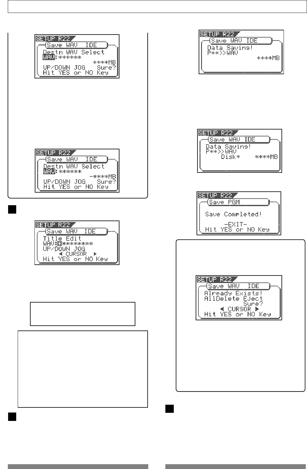
111
Save/Load of Song data
•Showing the title and "-****MB":
Even if the specified file is deleted, the space for
creating a new WAV file on the disk is ****MB short.
Pressing the [ENTER/YES] key shows "Disk Full!",
followed by "Delete All WAV?".
Pressing the [ENTER/YES] key again deletes all the WAV
file on the disk and advances to the next step (for
editing the file name).
After completing the save operation, only the new WAV
file will remain on the disk.
After selecting a file, press the [ENTER/YES] key.
The display shows the screen for editing the WAV file.
By rotating the [JOG] dial, you can set the desired
numeric, symbolic or alphabetical character to the
blinking point. You can move the blinking point by
using the [CURSOR] keys.
See the following table for the available characters.
Upper-case alphabetical characters (A to Z)
Numerals (0 to 9)
Symbols (! # $ % & ' ( ) @ ^ _ -)
<Note>
You can use up to 6 characters for a file name.
Some characters entered are converted as shown
below.
• Upper-case alphabetical characters (A to Z): not
converted
• Lower-case alphabetical characters (a to z):
converted to the corresponding upper-case
• Numerals (0 to 9): not converted
• Symbols (! # $ % & ' ( ) @ ^ _ -): not converted
• Other symbols: converted to "_".
After entering the file name, press the [ENTER/YES]
key.
The save operation is executed and the display shows
something like the one as below. As the file save goes
on, the remaining data size shown on the screen counts
down.
9
8
10
When saving data onto more than one disk, the current
disk number is shown on the screen as "Disk *" (where
* indicates the number).
Immediately after the data save to each disk is
completed, the disk is automatically ejected, and "Insert
Disk *" blinks on the screen, prompting you to insert
the next disk.
Inserting the next disk resumes the save operation.
After the save operation is completed, "Save
Completed!" appears on the screen.
<Hint>
In the save operation which requires more than
one backup disk, if you use a backup disk which
contains any program(s) saved, the display shows
the screen as shown below.
This screen is asking you weather to delete all
existing WAV files on the disk or to eject the disk.
To delete all the existing files, select "All Delete" and
press the [ENTER/YES] key. All existing files are
deleted and the disk is ready for saving data.
If you do not want to delete the existing files, select
"Eject" and press the [ENTER/YES] key.
The disk is ejected so you can insert another disk.
To select between "All Delete" and "Eject", press the
[CURSOR] key.
Press the [EXIT/NO] key (or the [STOP] key)
repeatedly until exiting the setup mode.
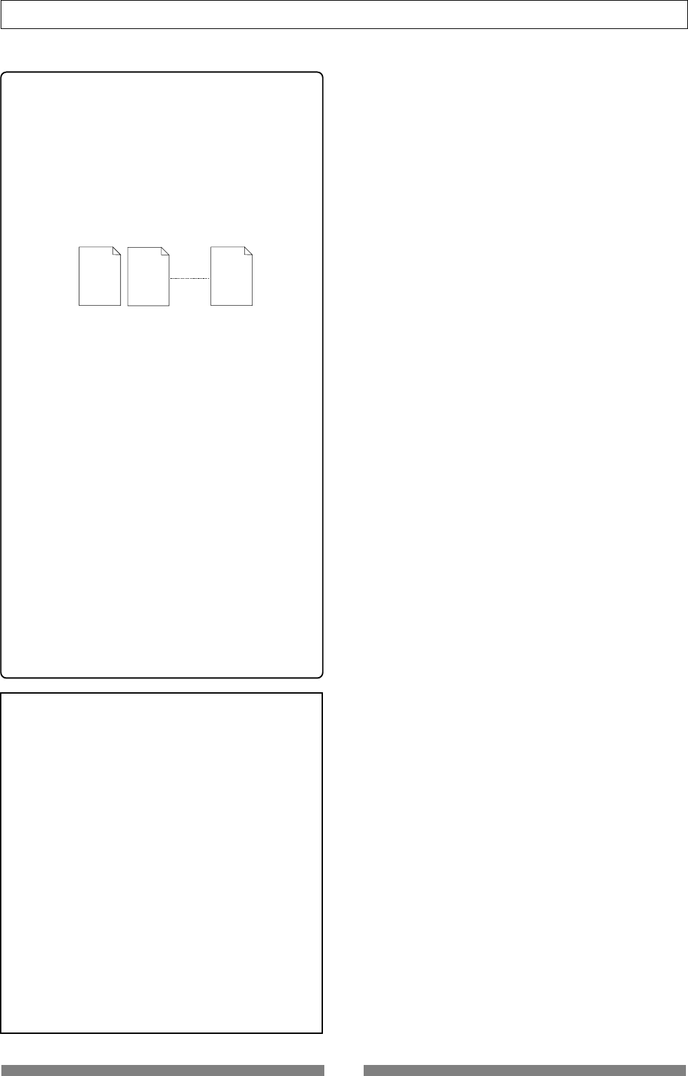
112
Save/Load of Song data
###### 01. WAV ###### 02. WAV ###### 24. WAV
<About WAV files saved>
•WAV file structure
A WAV file on the backup disk has 24 files (one file
per track) in the root directory of the disk.
The file names are "******01.WAV" through
"******24.WAV" where "******" shows the file name
specified in step 8 above and each number (01 - 24)
shows the corresponding track number.
If a track has no data recorded, the corresponding file
with no data is created.
•WAV file structure which is saved over more than
one disk
A WAV file is saved in order of track number (from
tracks 1 to 24).
During the save operation over more than one backup
disk, the VF80 always calculates the available space
of the disk automatically. If the VF80 knows that the
available space gets smaller than the data size of the
next track, it will change the disk when the data save
of the current track is completed.
•WAV file size
When saving data by the WAV file format to a backup
disk, the file size may sometimes increase compared
with the data size in the current drive, depending on
the recorded data condition such as the start time,
end time, the data amount, etc. on each track.
For example, if a track is recorded from ABS:0 (min.)
to ABS:1 (min.) and ABS:10 (min.) to ABS 11 (min.),
the file on the current drive has a length of 2 minutes,
while the WAV file has a length of 11 minutes.
Also as mentioned above, if a track has no data
recorded, the corresponding WAV file with no data is
created though the size is small.
<Notes>
• If the file name you are going to save duplicates
with the existing WAV file name on the backup disk,
"Warning! Already Exist" is shown on the screen and
the save operation will not be executed.
In such a case, change the file name according to
the procedure above and carry out the save
operation again.
• A disk on which you have overwritten data many
times may lower the access speed because of the
disk fragmentation. Therefore, we suggest that you
should use a newly formatted "clean" disk for
backup.
• If any other file but "******##.WAV" or folder, which
cannot be recognized by the VF80, is created on the
backup disk using a personal computer, the VF80
cannot calculate the available backup disk space
accurately. Accordingly, it may happen that the save
operation cannot be completed. You should note this
when changing the file name or creating a folder
using your computer.
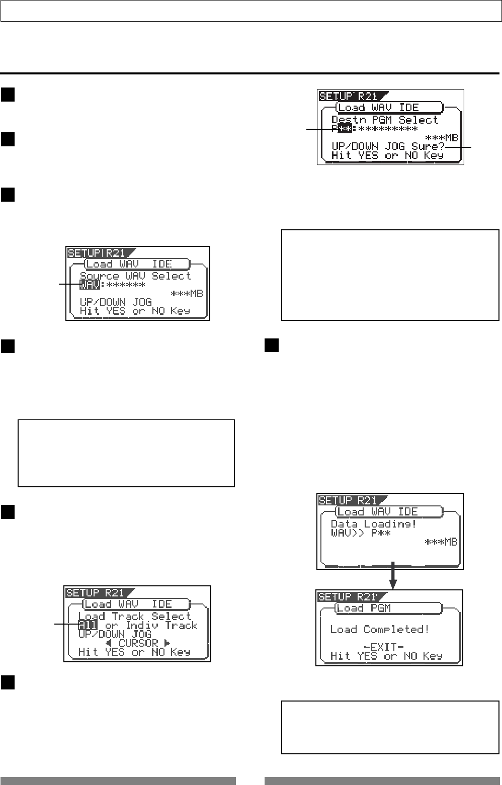
113
Save/Load of Song data
6
Loading a WAV file
Press the [SETUP] key to enter the setup mode.
The display shows the screen for selecting the Setup
menu.
Use the [JOG] dial to select "Load PGM" and press
the [ENTER/YES] key.
The display shows the screen for selecting the device
from which the data is loaded. "IDE" flashes.
While "IDE" is flashing, press the [ENTER/YES] key.
The display shows the drive name, followed by the
screen for selecting the WAV file to be loaded, showing
the WAV file name and size.
If no disk is inserted, "No SCSI Disk!" is shown.
Use the [JOG] dial to select the desired WAV file to
be loaded.
If more than one WAV file with different file names
(the first 6 characters) is saved, you can see each file
name (by the first 6 characters) in order when rotating
the [JOG] dial. You can also select "Eject" to remove
the backup disk.
<Note>
The VF80 cannot recognize any other file names
but "******##.WAV" and cannot load such disks. A
WAV file with an unique name (the first 6
characters) is recognized as an independent backup
file and can be selected.
After selecting the desired WAV file, press the
[ENTER/YES] key.
The display shows the screen for selecting a track to
be loaded. "All" flashes initially.
Besides "All", you can select any one of tracks (01
through 24) by rotating the [JOG] dial (or press the
[CURSOR] </> key).
After selecting the desired track(s), press the [ENTER/
YES] key.
The display shows the screen for selecting the load
destination program to which a WAV file is loaded.
You can select the program by using the [JOG] dial.
When the screen shows "Title" and "Size", the selected
program will be deleted and replaced with the WAV
file loaded.
When the screen shows "Title" and "New PGM", the WAV
file loaded will create a new program.
<Note>
If the current drive does not have enough available
space for loading the WAV file, the size indication
on the screen shows a negative value ("-***").
In such a case, select a program that can be replaced
with the WAV file loaded without causing the disk
space shortage, or delete unnecessary programs by
the "Delete PGM" menu in the setup mode.
After selecting the load destination program, press
the [ENTER/YES] key.
When selecting a new program as the load destination
(by selecting an option showing "Title" and "New
PGM"), the load operation immediately starts.
When selecting an existing program as the load
destination (by selecting an option showing "Title" and
"Size"), "Overwrite?" and "Sure?" appear.
Pressing the [ENTER/YES] key will start the load
operation.
During the load operation, the screen shows something
like the one as below.
As the data load goes on, the remaining data size shown
on the screen counts down.
When the load operation is completed, "Load
Completed!" appears on the screen.
1
2
3
4
5
7
Flashing
Flashing
<Note>
The title of the program to which the WAV file is
loaded is replaced with the WAV file name loaded
(the first 6 characters).
Flashing
Flashing
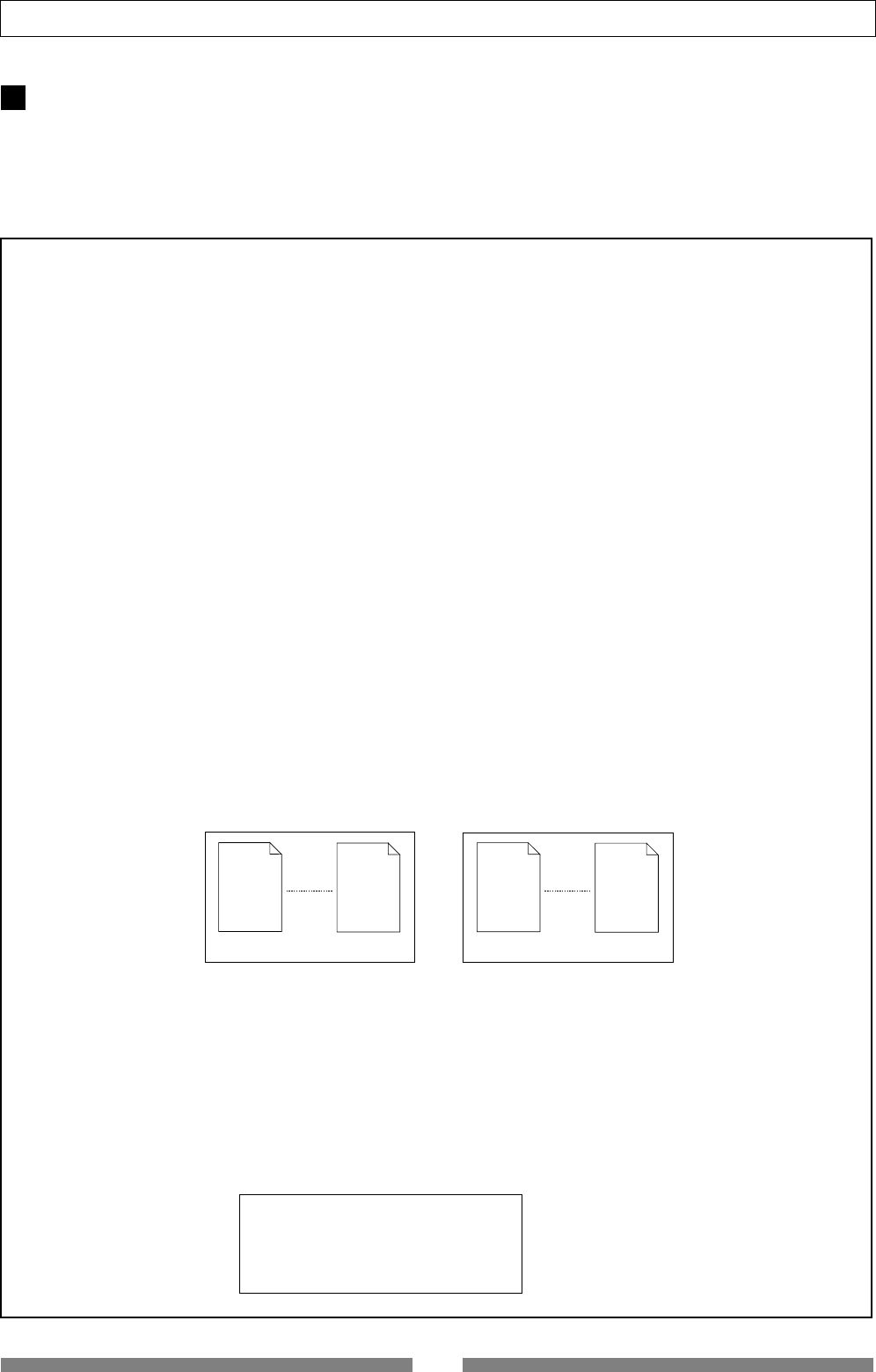
114
Save/Load of Song data
****** 01. WAV ****** 12. WAV
Backup Disk 1
****** 13. WAV ****** 24. WAV
Backup Disk 2
<< Special loading method when using a computer >>
(*) Method to load specific tracks.
The backup disk in which files are saved will contain files from “******01.WAV” up to “******24.WAV.” Should these
files be deleted, moved from the root directory, for example, into a another folder or the file name changed which
cannot be acknowledged, this recorder will not recognize this file.
When a backup disk changed in this manner is loaded, only WAV files with file names “******##.WAV” which are
located in an acknowledgeable root directory can be loaded.
For example, if the “zero number of data” made at save is deleted from the backup disk and then load is executed,
only WAV files recorded with any other sound can be loaded.
(*) When loading WAV files saved in a multiple number of disks, they can be loaded by a special method
derived from the above method.
Assume that there is backup disc 1 saved with “******01.WAV” through “******12.WAV” and disc 2 saved with
“******13.WAV” through “******24.WAV.”
First, when backup disk 1 is loaded, files in tracks 1-12 will be loaded. At this point, tracks 13-24 will not be loaded
and thus be non-recorded. Next, when backup disk 2 is loaded, files in tracks 1-12 remains intact and tracks 13-24
only will be loaded.
< Note>
WAV files which can be saved/loaded by this recorder must have file names written as “******##.WAV.”
Other file names cannot be acknowledged by this recorder.
Unknown file names will not be acknowledged and could cause malfunction. Extreme care should be taken when
changing file names and making folders on a computer.
* The first six letters will be the title shown in the SETUP mode “Title Edit” display.
* The last two letters “##” represent each track number (1-24) of the WAV file which are to be saved/loaded.
* The last “WAV” is the extension which indicate that this is a WAV file.
* File name of the WAV file which is to be saved in the backup disk of this recorder will all be recorded in capital
letters. However, in certain computers, this WAV file name will be displayed in small letters.
(*) Method in loading by changing the track.
If the two letters “##” in file name “******##.WAV” in the backup disk are changed, it will be possible to load them
on this recorder on a track different from that at the initial save. For example, if a WAV file named “ABCDEF01.WAV”
on track 1 is changed to “ABCDEF03.WAV” this WAV file will be loaded on track 3.
(*) Method in loading by changing the title.
If the 6 letters “******” in file name “******##.WAV” in the backup disk are changed, it will be possible to load them
on this recorder under a title different from that at the first save. Letters which can be used at changing the file
name in a computer are those only indicated below. All of these letters must be one byte size.
Alphabets : A-Z and a-z
Numerals : 0-9
Symbols : !#$%&’()@‘_=
Press the [EXIT/NO] key (or the [STOP] key) repeatedly
until exiting the setup mode.
To go back to the previous step or abort the operation,
you can also use the [EXIT/NO] key or the [STOP] key.
8
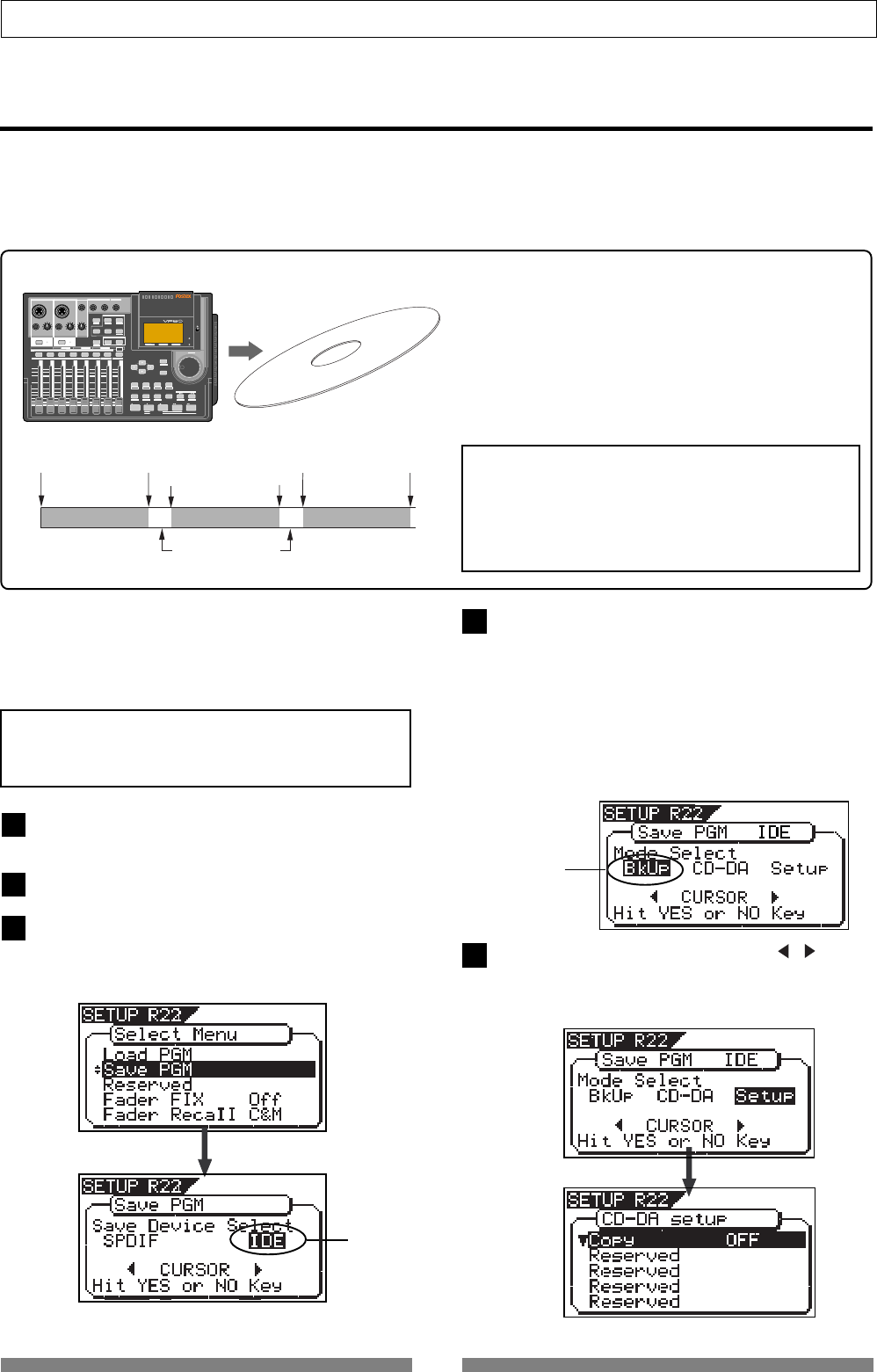
115
Save/Load of Song data
Making an audio CD
The following procedure describes how to record mastered songs (using the internal mastering function) to a
CD-RW/CD-R disc to make an audio CD (CD-DA format).
The “Save PGM” menu in the Setup mode, which is used for saving song data, is also used for making an audio
CD.
<Basic information>
When making an audio CD using the VF80, internal
mastering materials on the current drive are recorded
to a CD-RW/CD-R disc (by the CD-DA format).
You can record not only a single song but also mul-
tiple songs continuously.
When recording more that one songs continuously,
the VF80 automatically inserts a 2-second silent space
between songs.
VF80
CD-RW/CD-R disc
After turning on the power of the VF80, load a non-
recorded disc to the CD-RW drive.
Press the [SETUP] key to enter the Setup mode.
Use the [JOG] dial to select (highlight) the “Save PGM”
menu and press the [ENTER/YES] key.
The display shows the screen for selecting the device
to which the data is saved. “IDE” flashes.
<Note>
Key operations of the VF80 should be done after
completing access to a CD-RW/CD-R disc.
Press the [ENTER/YES] key while “SCSI” flashes.
After showing the model name of the connected CD-
RW drive, the display shows the screen for selecting
the save mode, in which “BkUp” flashes.
To carry out making an audio CD, select “CD-DA”.
If you need to change the copy protection setting (the
default setting is “OFF”), select “Setup” (for setting
writing conditions). If you make an audio CD without
changing the copy protection setting, skip steps 5 and
6 below and go to step 7.
Flashing
Use the [JOG] dial (or the [CURSOR] / key) to
select “Setup” and press the [ENTER/YES] key.
The display shows the “CD-DA Setup” screen, on which
you can select the copy protection setting (see the next
page).
<Figure-1>
<Figure-2>
<Note>
If an audio CD is made using a CD-RW disc, it can be
played back only by a player that supports CD-RW
playback. You cannot playback such a disc by a con-
ventional CD player that does not support CD-RW play-
back.
DIGITAL MULTITRACKER
LOCATE ABS 0
LOCATE REC END
SEL
TIMEBASE
CURSOR
PHANTOM
ACCESS
PEAK
CH ON/OFF
LR
GUITAR
GUITAR
LINE MIC LINE MIC MIN MAX
MASTERING TRAINING
EFFECTEQPAN
SCENE SEQ.SCENE
TRACK
UNDO
SETUP
PUNCH
AUTO LOOP PITCH SCRUB
VARI
F FWDREWINDPLAYSTOPRECORD
EXIT
ENTER
TRIMTRIM
WAVE FORM
MIX PARAMETER
PGM FADER MAP
ON/OFF
2TRK MODE
F1 F2 F3 SHIFT
EDIT EDIT EDIT MARK DELETE
LOCATE
FOOT SW
ST OUT
PHONES
INPUT A
BOUNCE
INPUT B
+6
-10
-20
-40
-
∞
-30
0
+6
-10
-20
-40
-
∞
-30
0
+6
-10
-20
-40
-
∞
-30
0
+6
-10
-20
-40
-
∞
-30
0
+6
-10
-20
-40
-
∞
-30
0
+6
-10
-20
-40
-
∞
-30
0
+6
-10
-20
-40
-
∞
-30
0
+6
-10
-20
-40
-
∞
-30
0
PEAK
CH ON/OFF
2 3 4 5 6 7/8 2TRK1 MASTER
TRACK STATUS / TRACK SEL
TRACK STATUS RED REC GREEN PLAY OFF MUTE STATUS
/SEL
EJECT
/YES
/NO
SHUTTLE
JOG
UNBAL UNBAL
BAL
BAL
F1 F2 F3
EDIT
/REDO
REC EFF
Silence (about 2 seconds)
Start point End point
123
Start point End point
Start point End point
Flashing
1
2
3
4
5
The following procedure assumes that there is a
program (song) mastered by the internal master-
ing function and the optional CD-RW drive (CD-
1A) is installed to the VF80.
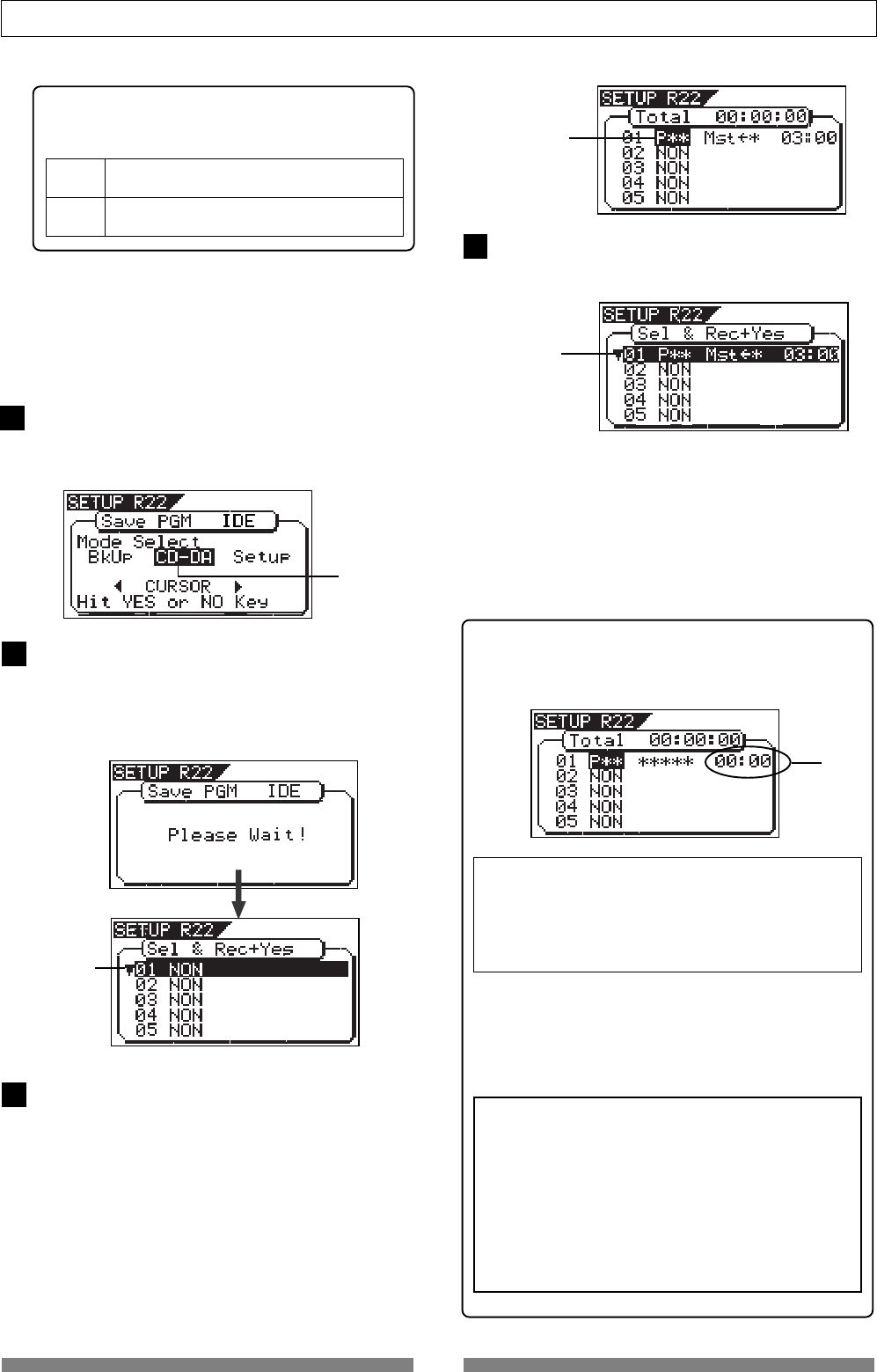
116
Save/Load of Song data
To change the setting, press the [ENTER/YES] key when
the “CD-DA Setup” screen is shown.
The current setting starts flashing, showing it can be
edited. While flashing, use the [JOG] dial to select
“ON” or “OFF”, then press the [ENTER/YES] key to con-
firm.
Copy protection setting
You can restrict the disc copy (duplication) capa-
bility of an audio CD you are going to make.
While “CD-DA” is flashing, press the [ENTER/YES] key.
After showing “Please Wait!”, the display shows the
screen for selecting the program(s) to be record.
In the screen, a number such as “01” or “02” shows the
track number, while “NON” shows that no program is
assigned to the track.
Use the [JOG] dial to select a desired program and
press the [ENTER/YES] key.
The selected program is set to the first track.
After setting the copy protection, press the [EXIT/NO]
key.
The display returns to the screen for selecting the save
mode, in which “CD-DA” now flashes.
“ON” A disc you made can be copied to other digital
device once.
“OFF” A disc you made can be copied to other digital
device as many times as required (default).
<Note>
If the program time shows
“00: 00”
when selecting a pro-
gram as the screen example below, the
“Start”
and
“End”
points are not correctly set.
In other words, in the following conditions, the “Start”
and “End” points are not regarded as being correctly
set.
“Start point” = “End point”
“Start point” > “End point”
If you press the
[ENTER/YES]
key after selecting such a
program, the warning message as below appears on
the display and you cannot select the program.
“Void In!”, “Void Out!”, or “Void Data!”
<Note>
It is possible to select a program that is not inter-
nal mastering if it holds the correct
“Start”
and
“End”
points.
However, if you record such a program to a CD-
RW/CD-R disc with the audio CD format, only track
1 and 2 can be recorded.
So, make sure that you select programs properly
when making an audio CD.
• To record a single song to a CD-RW/CD-R disc,
select a program and press the [ENTER/YES] key,
and then go to step 10.
• To record more than one song to a CD-RW/CD-R
disc, repeat the procedure for selecting a program
described above (i.e. use the [JOG] dial to select a
program and press the [ENTER/YES] key) until
selecting all desired programs, and then go to step
10.
Press the [ENTER/YES] key again.
The display shows the screen in which the last pro-
gram number of the current drive flashes.
Its program title and recording time are also shown,
while the total time of songs is shown at the top of the
screen.
Data between the "Start point" and "End point" is trans-
ferred to an audio CD.
Before executing recording, we recommend you to con-
firm that the actual audio in the program starts just
after the "Start point" and ends just before "End point".
Flashing
Flashing
Flashing
Flashing
6
7
8
9
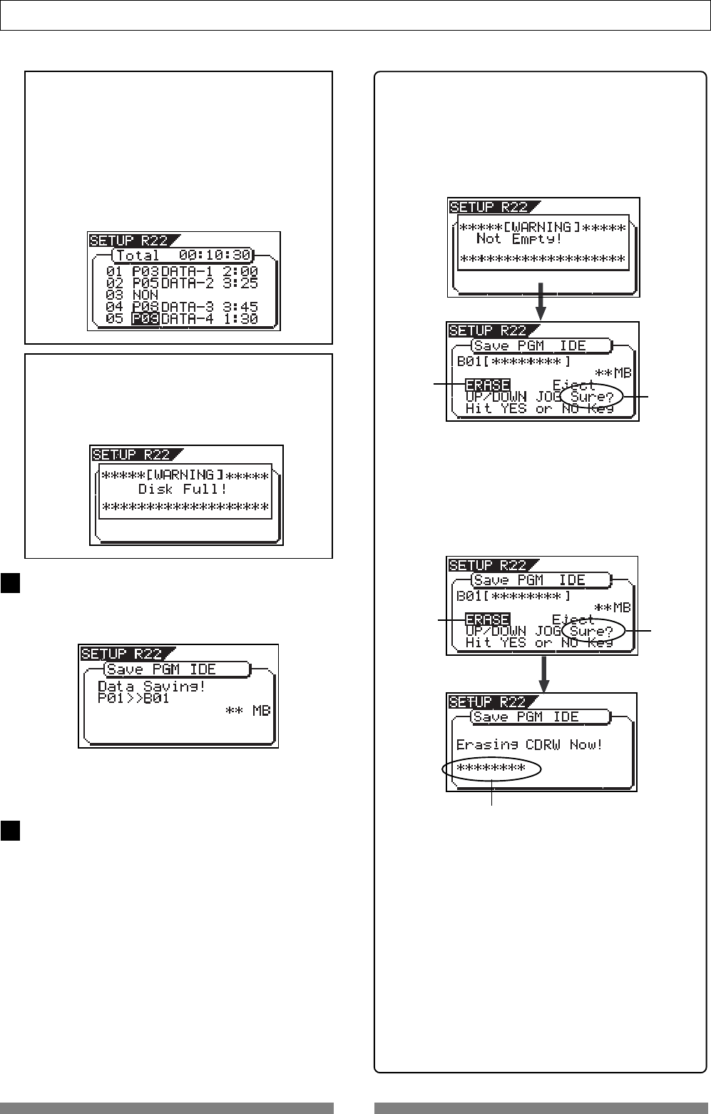
117
Save/Load of Song data
<Hint>
When a CD-RW disc on which any data is recorded
is set, if you perform step 7 above (i.e. pressing the
[ENTER/YES] key when “CD-DA” is flashing), “Not
Empty!” appears on the display, followed by the
screen for selecting whether erasing recorded data
or ejecting the disc.
• If you erase recorded data:
Press the [ENTER/YES] key while “ERASE” and
“Sure?” are flashing.
After the key press, the display changes as follows
and the VF80 starts erasing the data.
As the erasing process is going on, the number of
flashing “ * ” increases.
When erasing is completed, the display shows the
same screen which appears when pressing the [EN-
TER/YES] key after selecting “CD-DA” on step 7 above.
So follow the same procedure from step 8 on page
116.
Increases as the process progresses.
• If you eject the disc:
Use the [JOG] dial to make “Eject” flashing and then
press the [ENTER/YES] key.
The disc is ejected, while “Insert Disk!” appears on
the screen.
When inserting a blank disc, you can go on the next
step (see the procedure described above).
When the recording ends, “Save Completed!” appears
on the screen, while the disc is automatically ejected
from the CD-RW drive.
When completed, press the [EXIT/NO] key to quit the
Setup mode.
Flashing
Flashing
Flashing Flashing
After specifying the program(s), press the [ENTER/
YES] key while holding down the [RECORD] key.
The VF80 starts recording to the disc, while the dis-
play shows the following screen.
<Note>
When making an audio CD, if you select a program
which consumes more disc space than the record-
able space of a CD-RW/CD-R disc,
“Disk Full!”
ap-
pears on the display and you cannot select the pro-
gram.
<Notes for selecting more than one program>
When recording more than one program to a CD-
RW/CD-R disc, do not skip any track when assign-
ing programs to tracks.
If you skip any track, you cannot record data to the
subsequent tracks. In the following example, track
03 is skipped when assigning programs.
So only tracks 01 and 02 will be recorded. Tracks
03 and subsequent tracks can not be recorded.
10
11
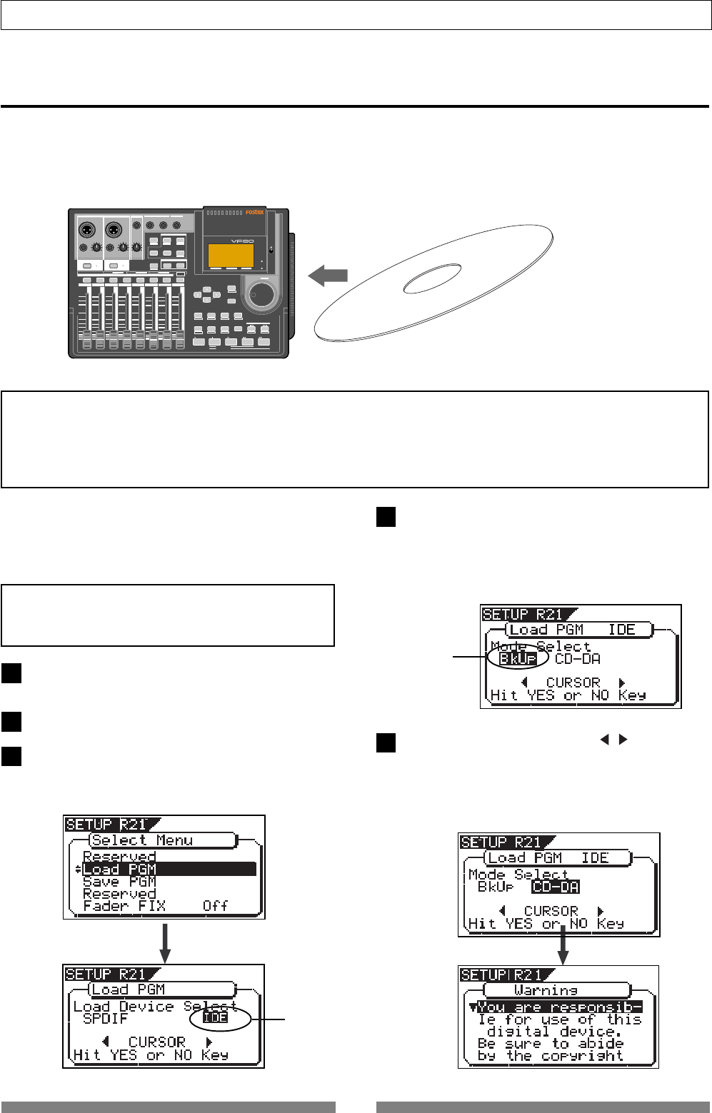
118
Save/Load of Song data
Loading from an audio CD
You can load a desired song to the VF80 from an audio CD you created by recording on a CD-RW/CD-R disc.
When a desired song is loaded, the VF80 automatically creates a new program on the current drive, and the
song are recorded on tracks 1 and 2 of the program. Loading data from an audio CD is operated via the
“Load PGM” menu in the Setup mode, which is the same way as loading backup data.
VF80
CD-RW/CD-R disc (or commercially available audio CD)
<Important note for copyright>
You can also load a material from a commercially available audio CD in the same manner, however, never use a
material for which a copyright is reserved for a commercial purpose.
Any unauthorized use will constitute infringement of such copyright and will render the infringer liable to an
action at low.
The following procedure assumes that the optional
CD-RW drive (CD-1A) is installed to the VF80 and
you have an audio CD you created (or available on
the market).
After turning on the power of the VF80, load a re-
corded audio CD disc to the CD-RW drive.
Press the [SETUP] key to enter the Setup mode.
Use the [JOG] dial to select (highlight) the “Load
PGM” menu and press the [ENTER/YES] key.
The display shows the screen for selecting the device
from which the data is loaded. “IDE” flashes.
<Note>
Do not carry out any VF80 key operation until the ac-
cess process to the CD-RW/CD-R disc is completed.
Flashing
Use the [JOG] dial (or [CURSOR] / key) to select
(highlight) “CD-DA”, then press the [ENTER/YES]
key.
A warning message for copyright appears.
You can scrolls the message to read all message by
rotating the [JOG] dial.
4. Press the [ENTER/YES] key while “IDE” flashes.
After showing the model name of the connected CD-
RW drive, the display shows the screen for selecting
the load mode, in which “BkUp” flashes.
To carry out loading a song from an audio CD, select
“CD-DA”.
DIGITAL MULTITRACKER
LOCATE ABS 0
LOCATE REC END
SEL
TIMEBASE
CURSOR
PHANTOM
ACCESS
PEAK
CH ON/OFF
LR
GUITAR
GUITAR
LINE MIC LINE MIC MIN MAX
MASTERING TRAINING
EFFECTEQPAN
SCENE SEQ.SCENE
TRACK
UNDO
SETUP
PUNCH
AUTO LOOP PITCH SCRUB
VARI
F FWDREWINDPLAYSTOPRECORD
EXIT
ENTER
TRIMTRIM
WAVE FORM
MIX PARAMETER
PGM FADER MAP
ON/OFF
2TRK MODE
F1 F2 F3 SHIFT
EDIT EDIT EDIT MARK DELETE
LOCATE
FOOT SW
ST OUT
PHONES
INPUT A
BOUNCE
INPUT B
+6
-10
-20
-40
-
∞
-30
0
+6
-10
-20
-40
-
∞
-30
0
+6
-10
-20
-40
-
∞
-30
0
+6
-10
-20
-40
-
∞
-30
0
+6
-10
-20
-40
-
∞
-30
0
+6
-10
-20
-40
-
∞
-30
0
+6
-10
-20
-40
-
∞
-30
0
+6
-10
-20
-40
-
∞
-30
0
PEAK
CH ON/OFF
2 3 4 5 6 7/8 2TRK1 MASTER
TRACK STATUS / TRACK SEL
TRACK STATUS
RED REC GREEN PLAY OFF MUTE STATUS
/SEL
EJECT
/YES
/NO
SHUTTLE
JOG
UNBAL UNBAL
BAL
BAL
F1 F2 F3
EDIT
/REDO
REC EFF
Flashing
1
2
35
4
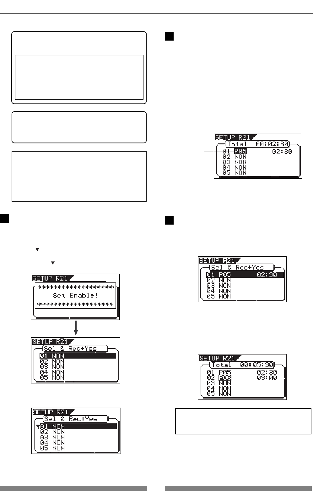
119
Save/Load of Song data
Warning!
You are responsible for use of this digital de-
vice. Be sure to abide by the copyright condi-
tions of the source material.
Press “Enter/Yes” key if you agree with the
above.
If you agree to the message contents, press the
[ENTER/YES] key.
After showing “Set Enable!”, the display shows the
screen for selecting the song(s) to be loaded.
If there is more than one track recorded on the au-
dio CD, “ ” flashes, showing that you can select a
desired track. If there is only one track recorded on
the audio CD. “ ” is not shown on the screen.
Use the [JOG] dial to select a track number to be
loaded and press the [ENTER/YES] key.
The destination program number starts flashing,
which is one greater than the highest program num-
ber among those available on the current drive.
This means a track is going to be loaded to a new
program.
For example, if there are 4 programs available on
the current drive, the destination program number(s)
on the current drive and then perform step 7 above
again. If there are already 99 programs on the cur-
rent drive, “Disk Full!” appears and no destination
program number is shown. In such a case, delete
the unnecessary program(s) on the current drive and
then perform step 7 above again.
To load more than one track, repeat steps 7 through
8 above.
The following screen example shows that tracks 1
and 2 will be loaded to program 05 and 06 respec-
tively. The track time is also shown to the left of
each program number.
<Hint>
The warning message above also appears when
setting the “Digital In setting” menu to “On”.
See “Setup mode” on page 130 for details.
<When only one track is recorded>
<When more than one track is recorded>
Flashing
<Note>
When loading from a audio CD, no title is shown
when selecting the track.
<Note>
If you do not agree with the warning message con-
tents, press the
[EXIT/NO]
key to quit loading.
The display briefly shows
“Set Disable”
and “
Can’t
Loading”
, then returns to the mode select screen.
If you agree with the warning message contents,
go to the next step to continue the operation.
By rotating the [JOG] dial, you can select “NON”, as
well as a “Program”. When performing the load op-
eration, tracks that are set to “NON” are not loaded.
While the program number is flashing, press the
[ENTER/YES] key.
The flashing program number changes to light sol-
idly, showing that the first track is ready to be loaded
to the program.
6
7
8
or
<Warning message>
The warning message for copyright shown on the
screen is as follows.
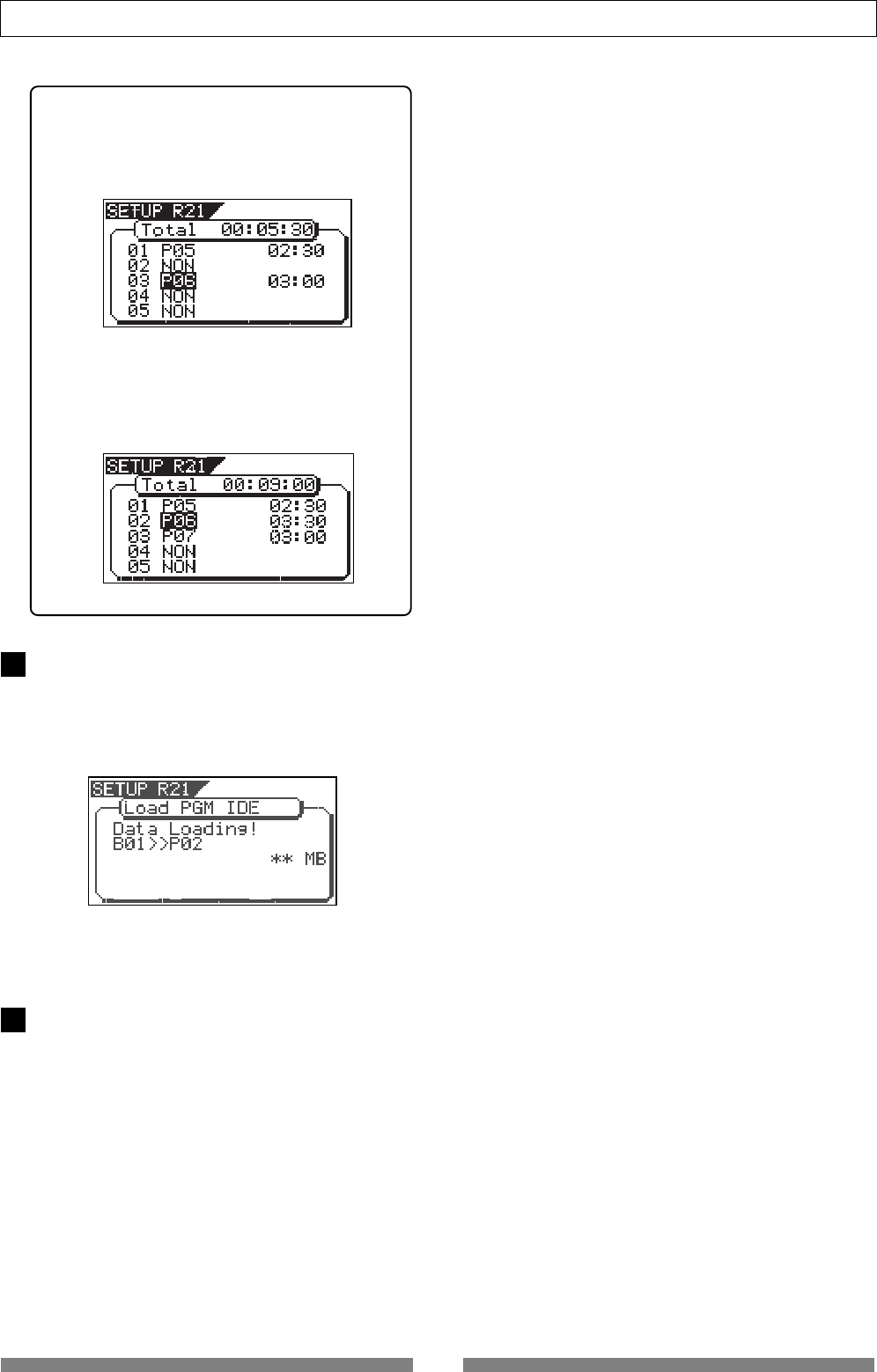
120
Save/Load of Song data
After specifying track(s) to be loaded, press the
[ENTER/YES] key while holding down the [RECORD]
key.
The VF80 starts loading tracks to the current drive.
The following screen example shows that track 1 is
now being loaded to program 02 on the current drive.
When the loading ends, “Load Completed!” appears on
the screen, while the disc is automatically ejected from
the CD-RW drive.
Press the [EXIT/NO] key to quit the Setup mode.
The display returns to the Normal display that was
shown last time before entering the Setup mode.
9
10
<Hint>
If you are going to load tracks 1 and 3 in the ex-
ample above, instead of tracks 1 and 2, track 3 will
be loaded to program 06 (see the screen example
below).
However, if you select track 2 after selecting tracks
1 and 3, the VF80 automatically reassigns track 2
to program 06 and track 3 to program 07 (see the
screen example below).
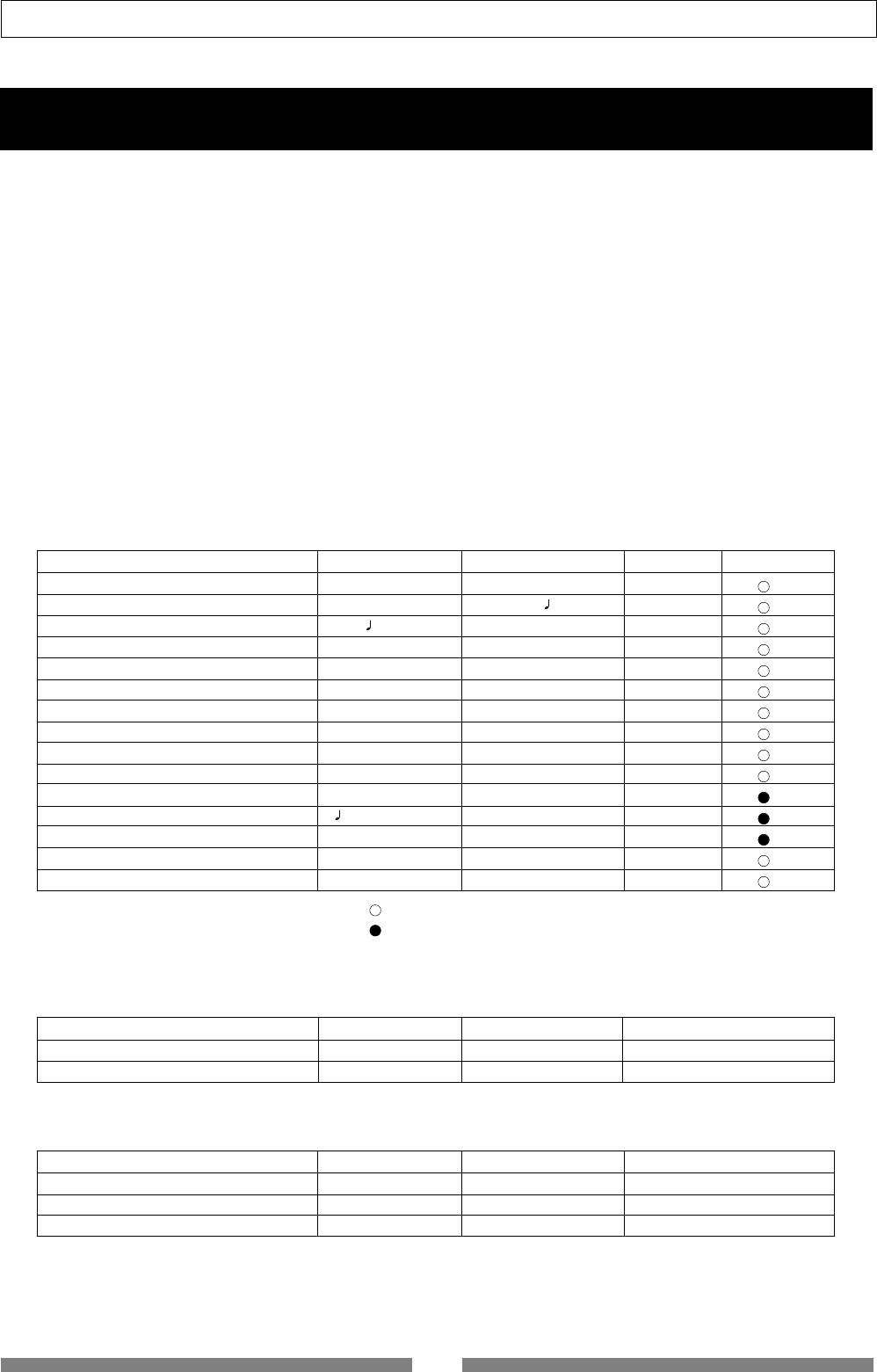
121
SETUP mode
SETUP mode
The SETUP mode of the VF80 offers the “Changing the initial settings” menus, which configure the operating
environment of the VF80, a “Check” menu that enables you to check the number of events for each track, and an
“Execution” menu that executes certain operations, such as save and load and disk formatting. The “Changing the
initial settings” menu include 15 parameters as shown in <Table-1> below. These parameters were set before the
VF80 was shipped from the factory and these values are called the “initial settings.” Modifying these settings allows
you to change the operating environment of the VF80. The “Check” menu provides two parameters “Checking the
number of events” as shown in <Table-2> - “Checking the number of events” and “Checking the current drive
information.”
Also, as shown in <Table-3>, the “Execution” menus include three items: Load PGM, Save PGM, and Disk Format,
which you can execute by selecting the corresponding SETUP menu. This chapter explains how to use the “Changing
the initial settings” menus shown in <Table-1> and the “Check” menu shown in <Table-2>.
For more information on the “Execution” menus, refer to the corresponding pages in the “Reference page” column
in <Table-3>.
<Table-3> “Execution” menu
Execution item Display Refer page Community
Saving song data to an external device Load PGM 96 -
Loading song data from an external device Save PGM 96 -
Formatting an current drive disk Disk Format 20 -
<Table-2> “Check” menu
Check item Display Refer page Community
Check of the event number on the track Number Of Event 131 -
Check of the current drive information Drive Information 132 -
<Table-1> “Changing the initial settings” menu
Parameters Display Default setting Refer page Community
Setting a time signature Signature Set 001BAR 4/4 122
Setting a tempo Tempo Set 001BAR 1 120 124
Setting the metronome function Click Off 125
Setting MIDI sync output signal Midi Sync Out MTC 126
Setting an MTC frame rate Frame Rate 25 frame 126
Setting an MTC offset value Mtc Offset 00h 59m 57s 00f 00sf 127
Setting the offset mode Offset Mode ABS 127
Setting the slave mode Slave Mode Off 128
Setting the slave type Slave Type Vari 128
Setting the record protect function Rec Protect Off 129
Setting digital input Digital In Off 130
Setting BAR/BEAT resolution mode Resolution Off 130
Setting the MIDI device ID number Device ID 00 131
Setting the fader fix mode Fader Fix Off 132
Setting the fader recall mode Fader Recall Off 133
: Modes applicable program by program. They can be saved/loaded.
: Modes applicable to all program. They cannot be saved/loaded.
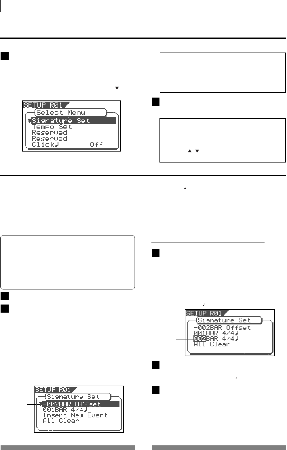
122
SETUP mode
Time signature setting [“Signature Set”]
Select a program for which to set a time signature.
In the menu selecting display, select “Signature Set” and
press the [ENTER/YES] key.
The display will change to confirming the currently set
signature. In the initial setting, the display will be as
shown below to indicate that the bar offset is -002BAR,
signature from the first bar is set to 4/4, and nothing is
set after the first bar.
If the [JOG] dial is rotated, items displayed can be
alternately selected. “-002BAR Offset” to setup the bar
offset figure, “Insert New Event” to setup a new signature
following the first bar, and “All Clear” to clear all signature/
tempo settings, can be selected.
To enter the SETUP mode
Entering the SETUP is possible only when the VF80 is in the Stop mode.
If the desired menu is selected via the [JOG] dial and the
[ENTER/YES] key pressed, you can proceed to the actual
setup procedure.
While the recorder is stopped, press the [SETUP] key on
the operating panel.
When the [SETUP] key is pressed, the recorder enters the
SETUP mode first stage and change to the display for
selecting the SETUP menu. The white black reversed title
indicates the currently selected menu and the (flash)
indicates that other titles exist below.
<Note>
At shipping from the plant or when power is switched
on again, the “Signature Set” menu will be reversed in
white-black. Otherwise, when exiting from the SETUP
mode, the SETUP menu that was displayed last will be
reversed in black and white.
<Important>
* To exit from the SETUP mode or return to the previous
level, press the [EXIT/NO] key (or [STOP] key).
* When selecting the desired SETUP menu, the
[CURSOR / ] keys can be used in addition to the
[JOG] dial.
• New Registering of Time Signature
While in the previous step 2 display, select “Insert
New Event” and press the [ENTER/YES] key.
The “Insert New Event” display section will change to
the display for setting up a new bar and the “002”
number will flash.
At this point, the bar figure displayed will be the bar
figure setup last +1 and the signature figure displayed
will be same as the last setting (Example: In the initial
state,“002BAR 4/4 ” will be shown.
Input the desired bar figure with the [JOG] dial and
press the [ENTER/YES] key.
It will change to flashing of “4/4 .”
Input the desired meter via the [JOG] dial and press
the [ENTER/YES] key.
The input bar and signature figures will be set as shown
in the following. This display is an example of setting
the third bar to 3/4 beat. If the [JOG] dial is rotated,
the editing point of bar or signature, like the figures
shown below, can be input.
Using the “Setting a time signature” menu, you can set a time signature of a given measure on the internal
programmable Tempo Map. Also in this setting, the BAR (-002BAR, 1 , 00CLK) displayed at the head of the
disk in the time base BAR/BEAT/CLK can be set within a range of -009BAR ~ -002BAR.
For example, you can specify 4/4 for the first and second measures, and 2/2 from the third measure.”
Setting a time signature and tempo will create a Tempo Map, which allows the VF80 to manage a song using
the BAR/BEAT/CLK Time Base. You can also use the Metronome function.
A time signature and tempo setting are required when MIDI clock & song position pointer are output to an
external sequencer.
* Initial Setting : 001bar 4/4 beat
* Available bars : 001 ~ 999
* Available time signature : 1/4, 2/4, 3/4, 4/4, 5/4, 1/8,
3/8, 5/8, 6/8, 7/8, 8/8, DEL
* Maximum setting points : 64
* The setting is applicable song by song.
* The setting can be saved or loaded as a part of the song data
* The setting is memorized even when the power is off.
* Make sure you choose the right program before setting this
mode.
flashing
flashing
1
2
1
2
3
4
5
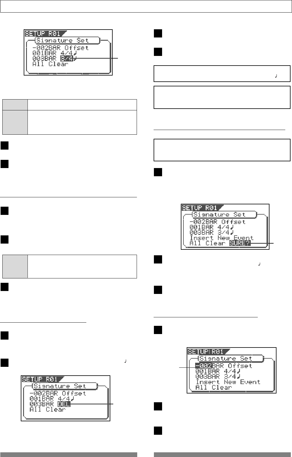
123
SETUP mode
<Note>
You cannot register the “001BAR“ of “001BAR 4/4
.”
• Correcting the Registered Time Signature
Under the previous “Confirmation display,” select bar/
time signatures to be changed and press the [ENTER/
YES] key.
Input the desired signature via the [JOG] dial and
press the [ENTER/YES] key.
The newly input signature will be setup.
<Note>
Be careful because this procedure wipes out the tempo
setting as well as time signature setting.
Under the above “Confirmation display,” select “All
Clear” and press the [ENTER/YES] key.
A following display of “All Clear,” “SURE ?” will flash.
This indicates the standby mode for clearing all
signature setting data and the tempo data.
• Clearing All Time Signature/Tempo Data
Under the above “Confirmation display,” select
“-002BAR Offset” and press the [ENTER/YES] key.
The “-002” display will change to flashing.
• Changing the Bar Offset Figure
Bar You can enter are from 001 to 999.
Time 1/4, 2/4, 3/4, 4/4, 5/4, 1/8, 3/8, 5/8, 6/8, 7/8, 8/8
Signature or DEL
“DEL” is used to deleted time signature data.
The following bar numbers and time signatures can be
entered via the [JOG] dial.
Next, to register other bar and time signature, repeat
steps 2 through 5.
Upon completion of registering, press the [EXIT/NO]
key (or the [STOP] key) and exit from the SETUP mode.
• Deleting a Time Signature
Press the [ENTER/YES] key.
The selected measure/signature setting will be deleted.
After deleting, press the [EXIT/NO] key (or [STOP] key)
to exit from the SETUP mode.
<Note>
Take care because this procedure wipes out the tempo
setting as well as time signature setting.
Under the above “Confirmation display,” select bar/
time signatures to be deleted and press the [ENTER/
YES] key.
Press the [ENTER/YES] key again to make “ */* ” to
flash and input “DEL” via the [JOG] dial.
Press the [ENTER/YES] key.
Except for the initial setting “001BAR 4/4 ,” other time
signature settings and the tempo setting will be cleared
at the same time.
Press the [EXIT/NO] key (or STOP key) to exit from
the SETUP mode.
Input the desired offset value with the [JOG] dial and
press the [ENTER/YES] key.
Offset value can be input in the -2 through -9 range.
After correction, press the [EXIT/NO] key (or [STOP]
key) to exit from the SETUP mode.
flashing
flashing
flashing
flashing
Upon finishing, press the [EXIT/NO] key (or [STOP]
key) to exit from the SETUP mode.
Time 1/4, 2/4, 3/4, 4/4, 5/4, 1/8, 3/8, 5/8, 6/8, 7/8, 8/8
Signature or DEL
“DEL” is used to deleted time signature data.
6
7
1
2
3
1
2
3
4
1
2
3
1
2
3
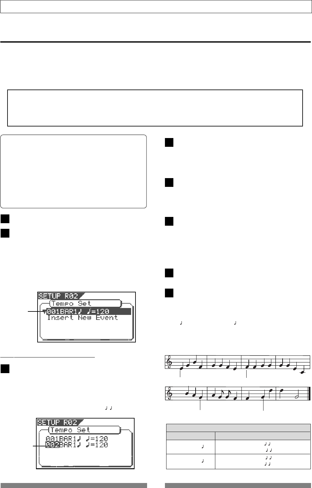
124
SETUP mode
Tempo Map
Time signature setting Tempo setting
001 BAR 4/4
005 BAR 3/4
001 BAR 1 = 120
003 BAR 1 = 90
005 BAR 3 = 60
007 BAR 2 = 120
Tempo = 120 Tempo = 90
Tempo = 60 Tempo = 120
4
4
4
3
Input the desired bar with the [JOG] dial and press
the [ENTER/YES] key.
The bar value that can be input is identical with the
above “signature setup.” When the [ENTER/YES] key is
pressed, “beat value” will change to flashing.
Input the desired beat with the [JOG] dial and press
the [ENTER/YES] key.
The meter value that can be input is identical with the
above “signature setup.” When the [ENTER/YES] key is
pressed, “tempo value” will change to flashing.
Input the desired tempo with the [JOG] dial and press
the [ENTER/YES] key.
The tempo can be input within the range of 30 through
250. When the [ENTER/YES] key is pressed, the tempo
map value thus input will be set and return to the
above mentioned “Confirmation display for tempo
map.”
To register another tempo map, repeat steps 1 through
4.
Upon completing registering, press the [EXIT/NO] key
(or [STOP] key) to exit from the SETUP mode.
For a setup example, if it is attempted to setup the
following tempo in the music that is set to [001BAR 4/
4 ] and [005BAR 3/4 ] by the previous “signature
setup,” as seen in the music score below, the tempo
Setting a tempo [“Tempo Set”]
• New Registering of Tempo
<Note>
The tempo set figure setup here is an approximate figure and thus not accurate. Therefore, although the tempo map be
matched with a personal computer, they will gradually drift apart. In order to prevent this drift, the personal computer
side can be set to either MIDI clock sync or, the MIDI sync output signal temporarily set to “MIDI Clock” the figure reset
to make it possible for the computer to read the accurate tempo, and the return it again to MTC sync.
The “Tempo Map Set” menu enables you to specify a tempo at a given point in a song that already has a time
signature setting. For example, you can specify a tempo of 150 to the third beat of the 12th measure.
Time signature and tempo settings make a Tempo Map, which is used by the VF80 to manage the song using the
BAR/BEAT/CLK time base, and enable the metronome function. Tempo settings as well as time signature settings
are required when you wish to output MIDI clock and Song Position Pointer to an external sequencer.
Under the above “Confirmation display,” select “Insert
New Event” and press the [ENTER/YES] key.
The “Insert New Event” section will change to new tempo
setup display and “002” will flash. The bar value thus
displayed will be the last setup bar value +1 and tempo
value will be identical with the last setting (Example:
In the initial setup state, “002BAR 1 =120” will be
displayed.
Select a program for which to set a tempo setting.
Under the menu selection display, select “Tempo Set”
and press the [ENTER/YES] key.
The display will change, confirming the current tempo
setting. At the initial setting, the display will be as
shown below, indicating that tempo of the first beat
for the 001 bar is 120 and subsequent tempo is not
setup. “Insert New Event” should be selected at setup
of a new tempo. When the [JOG] dial is rotated, the
currently displayed items can be selected alternately.
* Initial Setting: 001BAR 1st beat 120 bpm
* Bar to register: Follows to the time signature setting
* Beat to register: Follows to the time signature setting
* Available tempo: 30 ~ 250, DEL (delete)
* Maximum setting points:64
* The setting is applicable song by song.
* The setting can be saved or loaded as a part of the
song data
* The setting is memorized even when the power is off.
* Make sure you choose the right program before setting
this mode.
flashing
flashing
1
2
1
2
3
4
5
6
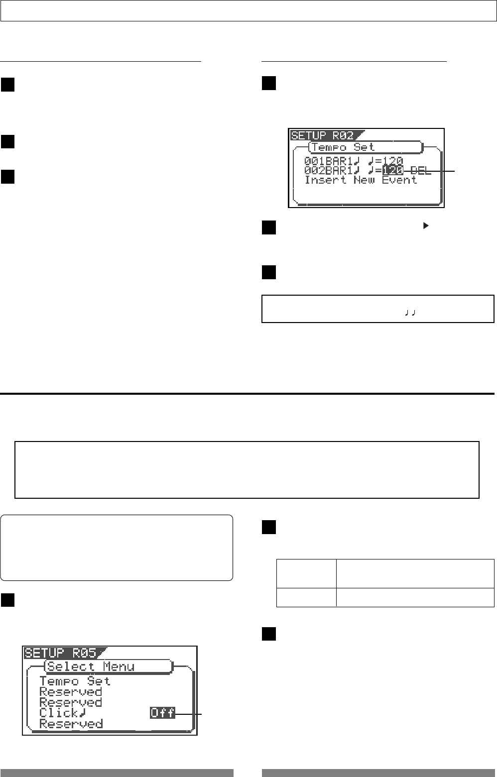
125
SETUP mode
• Erasing of the Registered Tempo
Setting the Metronome function [“Click”]
<Note>
Metronome sound will be output from track 6.
For this reason, when the metronome function is activated, a new sound source cannot be recorded on the
track to which the metronome sound is to be output or sound recorded on this track cannot be played back.
If the metronome function is not to be used, be sure to reset it to “Off.”
Select “Click” in the menu selection display and press
the [ENTER/YES] key.
The currently set item (Off or On) will flash (“Off” will
flash if in the initial state).
Select “On” or “Off” with the [JOG] dial and press
the [ENTER/YES] key.
The selected item will be setup.
“Setting the Metronome function” menu allows you to determine whether or not the VF80 outputs a metronome
sound from track 6 during playback or recording. Turning the Metronome function on enables you to record your
performance while playing the instrument accompanying the metronome sound.
• Correction of the Registered Tempo
Under the above “Confirmation display,” select the
tempo map which is to be changed and press the
[ENTER/YES] key.
The same as before, “tempo value” will flash.
Input the desired tempo with the [JOG] dial and press
the [ENTER/YES] key.
Upon completing registering, press the [EXIT/NO] key
(or [STOP] key) to exit from the SETUP mode.
Under the above “Confirmation display,” select the
tempo map which is to be erased and press the
[ENTER/YES] key.
The same as before, “tempo value” will flash.
On Metronome sound will be output from
track 6.
Off (default) Metronome sound will not be output.
Press the [EXIT/NO] key (or [STOP] key) to exit from
the SETUP mode.
Upon completing registering, press the [EXIT/NO] key
(or [STOP] key) to exit from the SETUP mode.
* Initial Setting : [Off]
* Available setting : [Off] or [On]
* The setting is applicable song by song.
* The setting can be saved or loaded as a part of the song data
* The setting is memorized even when the power is off.
* Make sure you choose the right program before setting this
mode.
<Note>
You cannot register the “001BAR 1
=120.”
flashing
flashing
Input the “DEL” with the [CURSOR ] key, and then
press the [ENTER/YES] key.
The selected tempo map will be erased.
1
2
3
1
2
3
1
2
3
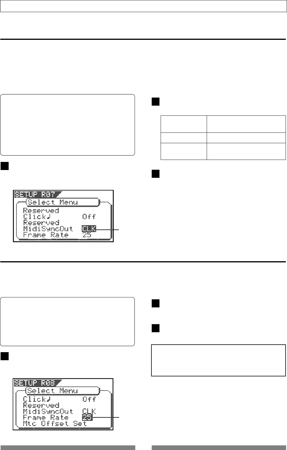
126
SETUP mode
Select the desired MIDI sync signal with the [JOG]
dial and press the [ENTER/YES] key.
Setting MIDI sync output signal [“Midi Sync Out”]
Select “Midi Sync Out” in the menu selection display
and press the [ENTER/YES] key.
The currently set item will flash. “CLK” will flash in
initial setting.
CLK (Initial setting) MIDI clock and song position
pointer will be output.
Mtc MIDI time code will be output.
Off Any MIDI sync signal will not
be output.
Press the [EXIT/NO] key (or STOP key) to exit from
the SETUP mode.
The “Setting MIDI sync output signal” menu enables you to select the type of MIDI sync signals output from
the MIDI OUT connector on the rear panel of the VF80 to an external MIDI device.
The options are MIDI clock & Song Position Pointer, or MTC (MIDI time code). Select an appropriate option
depending on the type of signal supported by the connected MIDI device.
If you select MIDI clock & Song Position Pointer, first you need to set the time signatures and tempo as
described previously. If you select MTC, you first need to set the MTC frame rate, the MTC offset time, and the
MTC offset mode as described later.
• Initial setting: [Mtc]
• Option: [CLK] (clock & Song Position Pointer),
[MTC] (MIDI time code), or [Off] (no
output)
* You can set the parameters for each Program
individually.
* The settings can be saved and loaded as part of the
song data.
* The settings are maintained after you turn off the
power to the VF80.
flashing
Setting an MTC frame rate [“Frame Rate”]
<Note>
There are no 29.97nd or 29.97df in the MTC standard.
Use either 30nd or 30df unless you definitely need to
synchronize the VF80 with NTSC video.
Select “Frame Rate” in the menu selection display and
press the [ENTER/YES] key.
The currently set frame rate will flashes. “25” will flash
in the initial setting.
Select the desired frame rate value with the [JOG]
dial and press the [ENTER/YES] key.
It will be set to the selected frame rate.
Press the [EXIT/NO] key (or STOP key) to exit from
the SETUP mode.
The “Setting an MTC frame rate” menu enables you to set the frame rate for MTC output from the MIDI OUT
connector of the VF80 to an external MIDI device. If you have already set the type of MIDI sync output signal
to [MTC], you need to set the frame rate. Use the frame rate of MTC received by the external MIDI device (or
sequence software).
• Initial setting: [25] (25 frames)
• Setting range of frame rate: [24], [25], [29df],
[29nd], [30df] or [30nd]
* You can set the value for each Program individually.
* The settings can be saved and loaded as part of the
song data.
* The settings are maintained after you turn off the
power to the VF80.
flashing
1
2
3
1
2
3
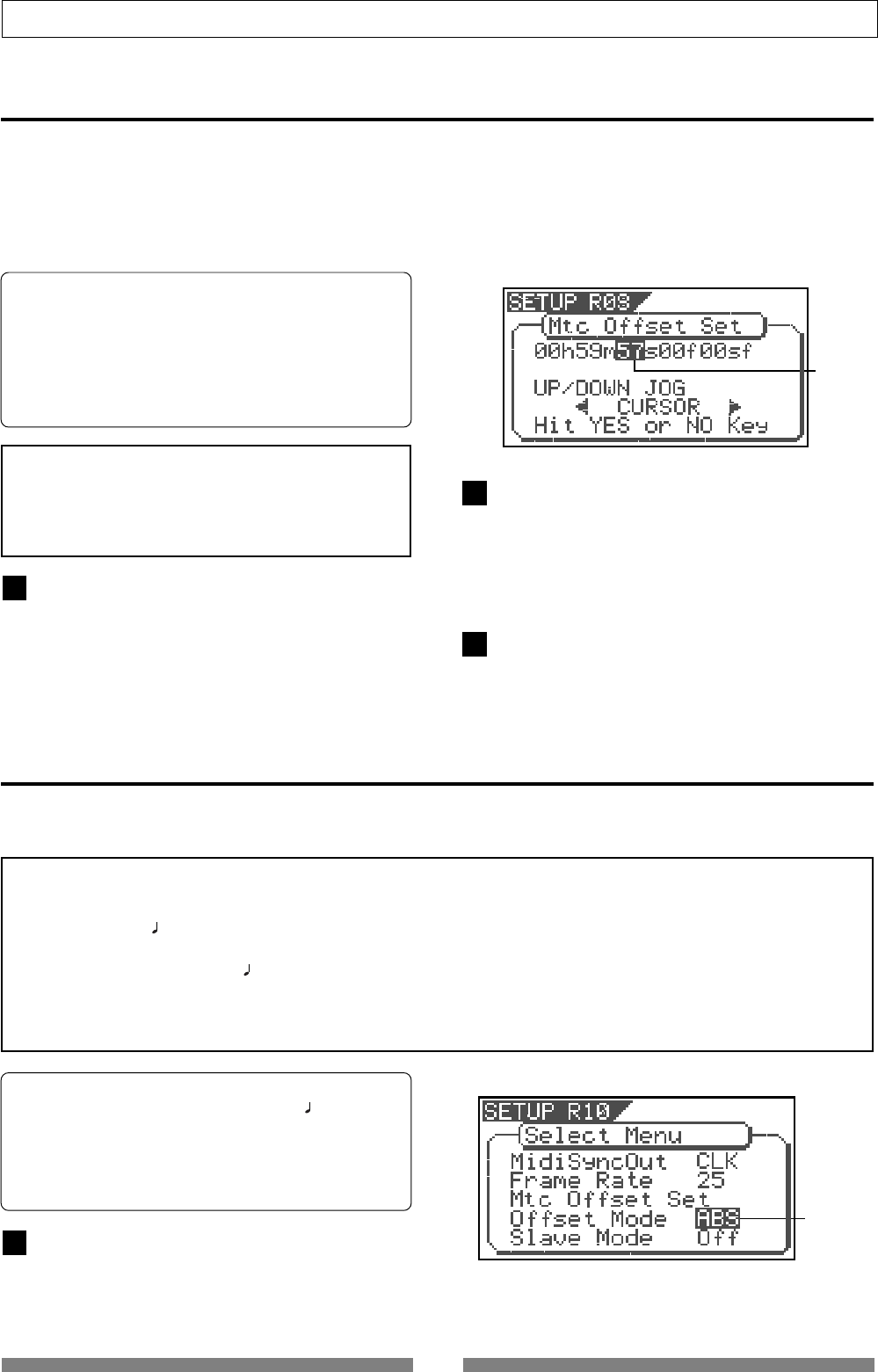
127
SETUP mode
Setting MTC Offset mode [“Offset Mode”]
Select “Offset Mode” in the menu selection display
and press the [ENTER/YES] key.
The currently set offset mode will flash. “ABS” will
flash in the initial setting.
If you have selected [MTC] in the “Setting Offset mode” menu, you need to select MTC Offset mode.
This menu enables you to determine whether the specified MTC is output at ABS 00h 00m 00s 00f or at
001bar 1beat 00clk (bar/beat) of the Tempo Map.
<Notes>
* As an example, if you set MTC Offset mode to “ABS” and you wish to start the song from MTC’s 1h 00m 00s 00f, you
may want to set a preroll of three seconds with MTC offset of 00h 59m 57s 00f.
If you select “Bar “ as the MTC Offset mode, a preroll of two measures is automatically set. Use 01h 00m 00s 00f; do
not set a preroll value.
* If you set Offset mode to “Bar “ and use MTC to synchronize sequence software on the computer, the tempo of the
sequencer may sometimes slip gradually. This is because the tempo of the VF80 and the tempo of the software are
slightly different even if both use the same tempo. Some sequence software can read the tempo output from the VF80
correctly. We recommend that you use the tempo of the VF80 on the sequence software. No such problems will
occur if the sequence software synchronizes the VF80 via MIDI clock, instead of MTC.
• Initial setting: [ABS]
• Offset mode option: [ABS] or [Bar ]
* You can set the mode for each Program individually.
* The settings can be saved and loaded as part of the
song data.
* The settings are maintained after you turn off the
power to the VF80.
Setting an MTC offset value [“Mtc Offset Set”]
Select “Mtc Offset Set” in the menu selection display
and press the [ENTER/YES] key.
It will change to the second level display of the [Mtc
Offset] menu and the currently set offset value will be
shown.
00h 59m 00f 00sf will be displayed in the initial state
and “s” will flash. Flashing indicates the editable point.
Move the edit point with the [CURSOR] key, input the
desired offset with the [JOG] dial, then press the
[ENTER/YES] key.
Offset value thus input will be set.
Advancing or retarding the input figure is carried out
automatically with reference to the currently set MTC
frame rate figure.
Press the [EXIT/NO] key (or STOP key) to exit from
the SETUP mode.
The “Setting an MTC offset value” menu enables you to specify an offset time value - the difference between
the time of MTC output from the VF80 and the ABS 00m 00s 00f 00sf time. You need to specify this value if
you have selected [MTC] for the “Setting MIDI sync output signal” menu.
With the initial setting of 00h 59m 57s 00f 00sf, for example, MTC of 59m 57s 00f 00sf is output at the ABS
time 00m 00s 00f 00sf. You can also set an offset value from the 001bar 1beat 00clk value (bar/beat) on the
Tempo Map. Refer to the next section for information on MTC Offset mode.
• Initial setting: [00h: 59m: 57s: 00f: 00sf]
• Setting range of offset time: 00h: 00m: 00s: 00f: 00sf
~ 23h: 59m: 59s: 29f: 99sf
* You can set the value for each Program individually.
* The settings can be saved and loaded as part of the
song data.
* The settings are maintained after you turn off the
power to the VF80.
<Note>
For example, if you set MTC Offset mode to “ABS” (See the
next section) and you wish to start the song from MTC’s
01h 00m 00s 00f, you may wish to set a preroll of three
seconds with an MTC offset of 00h 59m 57s 00f.
flashing
flashing
1
2
3
1
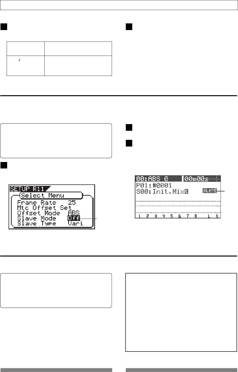
128
SETUP mode
Select the desired offset mode with the [JOG] dial
and press the [ENTER/YES] key.
The selected offset mode will be set.
Setting the Slave mode [“Slave Mode”]
This mode allows you to choose the VF80 slave mode setting either On or Off.
If you set the slave mode to “On”, the VF80 will synchronize to the incoming MTC (MIDI Time Code) from
master unit. It will also synchronize to a type of external sync signal which you have chosen with the section
“Slave Type setting.”
Select “Slave Mode” in the menu selection display and
press the [ENTER/YES] key.
The currently set slave mode will flash. “Off” will flash
in the initial setting.
Select “On” or “Off” with the [JOG] dial and press the
[ENTER/YES] key.
Press the [EXIT/NO] key (or STOP key) to exit from
the SETUP mode.
Upon exit from the SETUP mode, the “SLAVE” icon
will flash.
This icon will change to constant lighting when VF80
is correctly synchronized with the external equipment.
[ABS] (Initial setting) The specified MTC offset time is
output at ABS 00h 00m 00s 00f.
[BAR ] The specified MTC offset time is
output at 001bar 1beat 00clk of
the Tempo Map.
Press the [EXIT/NO] key (or STOP key) to exit from
the SETUP mode.
• Initial setting: [Off]
• Slave mode option: [On] or [Off]
* You can set the mode for each Program individually.
* The settings can be saved and loaded as part of the
song data.
* The settings are maintained after you turn off the
power to the VF80.
flashing
flashing
Setting the Slave Type [“Slave Type”]
If you have set Slave Mode to “On” in the previous section “Slave Mode Setting,” you can choose what type of
external sync signal that the VF80 synchronizes to. This mode allows you to choose the external sync signal type.
<Notes>
* You need to input MTC from an external device to the
VF80 with any Slave Type.
* The VF80 re-chase window is fixed to ten frames. That
is, if an offset between the master device and slave device
exceeds ten frames, the VF80 interprets that as out of
sync, and tried to chase and lock to MTC sent from the
master device. This operation is called “re-chasing.”
During the re-chase operation, audio output is muted.
If the slave machine slips with MTC from the master
device by less than ten frames, the slave machine
continues running while recognizing the slippage.
* When you set the Slave Type, the Vari Pitch function is
automatically disabled. (The “VARI PITCH” indicator
turns off.)
• Initial setting: [Vari]
• Slave type option: [Vari], [Free] or [SPDIF]
* You can set the mode for each Program individually.
* The settings can be saved and loaded as part of the
song data.
* The settings are maintained after you turn off the
power to the VF80.
2 3
1
2
3
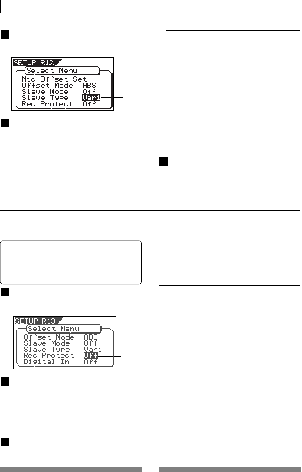
129
SETUP mode
Setting the Record Protect function [“Rec Protect”]
The “Setting the Record Protect function” menu allows you to turn the Record Protection function On or Off.
When this function in turned “On”, you cannot record, paste, or erase data. Use this function to protect your
important data from being accidentally erased.
Select the desired slave type with the [JOG] dial and
press the [ENTER/YES] key.
It will be set to the selected slave type.
Select “Slave Type” in the menu selection display and
press the [ENTER/YES] key.
The currently set slave type will flash. “Vari” will be
flash in the initial setting.
Press the [EXIT/NO] key (or STOP key) to exit from
the SETUP mode.
Select “Rec Protect” in the menu selection display
and then press the [ENTER/YES] key.
The presently set item (On or Off) will flash.
“Off” will flash in the initial setting.
Select “On” or “Off” with the [JOG] dial and then press
the [ENTER/YES] key.
It will be set to the selected item (On or Off).
Selecting “Off” enables recording; you can record,
paste, and erase data.
Selecting “On” disables recording; and you cannot
record, paste, or erase data.
Press the [EXIT/NO] key (or STOP key) to exit from
the SETUP mode.
• Initial setting: [Off]
• Options: [On] or [Off]
* You can set the mode for each Program individually.
* The settings can be saved and loaded as part of the
song data.
* The settings are maintained after you turn off the
power to the VF80.
This is the mode whereby after chase
locking, it will free run by the internal
clock of VF80 or the digital in clock
from the external equipment should
the time drift away from that of the
master.
This is the mode whereby after chase
locking, it will constantly run by vari-
pitch so that the time does not drift
away from that of the master by
compensating the phase drift.
However, if digital in has been set, it
will operate the same as for “Free.”
This is the mode whereby after chase
locking, it will free run by the S/P DIF
clock only when there is S/P DIF digital
signals from the master.
However, if digital in has been set, that
clock will have priority.
<Note>
When recording is disabled (“On”) and you try to record,
paste, or erase data, the VF80 displays “Protected!” for a
second, indicating that you cannot perform the operation.
To perform the operation you need to enable recording
(“Off”).
flashing
flashing
Free
Vari
(Initial setting)
SPDIF
1
2
3
1
2
3
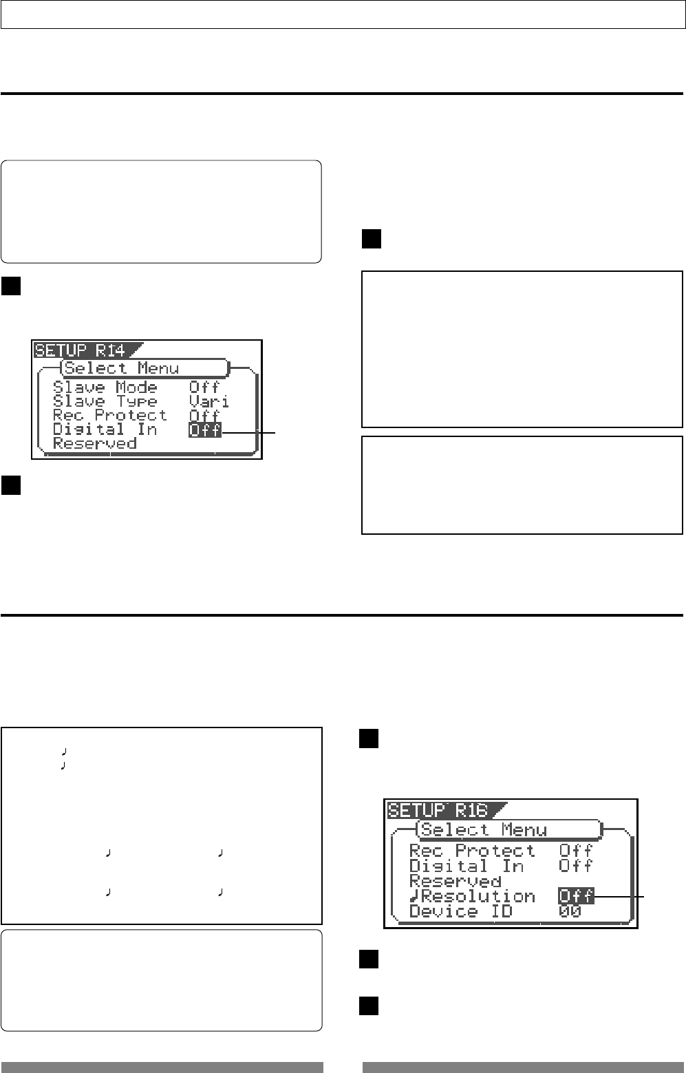
130
SETUP mode
Setting Digital Input [“Digital In”]
In the [Setting digital input] menu, whether the signal assigned to tracks 7 and 8 are S/P DIF digital signal
analog signals, can be setup. By using this function, it becomes possible to digitally record from external
digital equipment (CD, MD, DAT, adat, digital mixer, etc.).
• Initial setting: [Off]
• Options: [On] or [Off]
* You can set the mode for each Program individually.
* The settings cannot be saved and loaded as part of
the song data.
* The settings are maintained after you turn off the
power to the VF80.
Setting BAR/BEAT Resolution mode [“Resolution”]
For example, assume that you have stored the value for
001bar 1 46 clk as the START point, and the value for
002bar 4 51 clk as the END point.
These values will be used as they are if BAR/BEAT
resolution mode is turned off. However, the mode is
turned on, the following values will be stored instead.
The following example has a time signature setting of 4/
4.
001 bar 1 46 clk -> 001 bar 1 00 clk
(A clk value of 46 will be rounded off.)
002 bar 4 51 clk -> 003 bar 1 00 clk
(A clk value of 51 will be rounded up.)
The “Setting BAR/BEAT resolution mode” menu enables you to turn BAR/BEAT resolution mode on and off.
The initial setting is “Off.” When you turn this mode “On”, the CLK (clock) digits will be always round off to “00”
and be stored in the memory key while the VF80 is using the BAR/BEAT/CLK time base.
That is, beat-resolution is used. Using this function allows you to automatically store a beat-resolution value of the
IN/OUT points, START/END points and END point in real-time. Therefore, it is very convenient when you perform
the Copy & Paste or Move & Paste operation in beat-resolution.
Select “Resolution” in the menu selection display and
press the [ENTER/YES] key.
The presently set item will be flash (On or Off).
“Off” will flash in the initial setup.
Select “On” or “Off” with the [JOG] dial and press the
[ENTER/YES] key.
Press the [EXIT/NO] key (or STOP key) to exit from
the SETUP mode.
• Initial setting: [Off]
• Options: [On] or [Off]
* You can set the mode for each Program individually.
* The settings cannot be saved and loaded as part of
the song data.
* The settings are maintained after you turn off the
power to the VF80.
flashing
Select “Digital In” in the menu selection display and
then press the [ENTER/YES] key.
The presently set item (On or Off) will flash.
“Off” will flash in the initial setting.
flashing
1
Select “On” or “Off” with the [JOG] dial and then press
the [ENTER/YES] key.
It will be set to the selected item (On or Off).
When selecting “On” and pressing the [ENTER/YES]
key, “Warning” message appears.
2
3
1
2
3
<Note>
When setting “Digital In” to “On”, “DIGI IN” appears on
the Normal screen. While the VF80 receives a valid S/P
DIF digital signal from an external digital device and is
locked to it, “DIGI IN” steadily lights. While the VF80 does
not receive a valid S/P DIF signal, “DIGI IN” blinks.
If “DIGI IN” blinks when sending an S/P DIF signal from
the external device, check the connection between the VF80
and the external device, as well as the settings (for the
digital output, etc) of the external device.
<Note>
When “Digital In” is set to “On”, if you enter the bounce,
training or mastering mode, the “Digital In” setting is
automatically changes to “Off.” Therefore, to perform the
digital recording after exiting the move above, you must
set “Digital In” to “On” again.
Press the [EXIT/NO] key (or STOP key) to exit from
the SETUP mode.
You can scroll the message by rotating the [JOG] dial.
If you agree to the message, press the [ENTER/YES] key
again. If you do not agree to the message, press the
[EXIT/NO] key to stop setting.
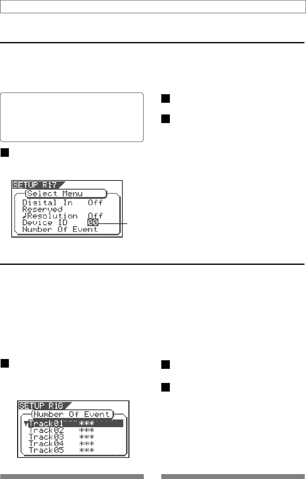
131
SETUP mode
Select desired device number with the [JOG] dial and
press the [ENTER/YES] key.
Press the [EXIT/NO] key (or STOP key) to exit from
the SETUP mode.
Setting the MIDI device number [“Device ID”]
The “Setting the MIDI device number” menu enables you to set the VF80 device ID number required to control the
VF80 from a sequence software using MMC (MIDI Machine Control).
The transmit device ID links to this setting. You can set the device ID from 00 to 99.
However, if the device ID number of the message the VF80 receives is [7F], the VF80 will recognizes it to perform the
corresponding operation, regardless of its device ID setting.
• Initial setting: [00]
• Options: [00] ~ [99]
* You can set the mode for each Program individually.
* The settings cannot be saved and loaded as part of
the song data.
* The settings are maintained after you turn off the
power to the VF80.
Select “Device ID” in the menu selection display and
press the [ENTER/YES] key.
The presently device number will be flash.
“00” will flash in the initial setup.
flashing
Checking the number of track events [“Number Of Event”]
Select “Number of Event” in the menu a selection display
and press the [ENTER/YES] key.
It will change to the "Event" second level and the
event number currently in each track will be dis-
played (The * symbol indicates there is data below).
*** is the event number.
Use the [JOG] dial to select another (01~24) to check
the number of events on the corresponding track.
Press the [EXIT/NO] key (or [STOP] key) to exit from the
SETUP mode.
The “Checking the number of track events” menu enables you to check the number of events on each track.
Each track (including Additional tracks) of VF80 Programs consists of consecutive audio files (and “zero”
files). The number of events represents the total number of audio files and 0 files. Each track can contain up
to 512 events.
If you are editing a song of typical length (about six minutes), repeated editing operation does not usually
exceed this maximum number. (Exceeding this limit is called “event number overflow.”) Even a 20-minute
song will not cause event number overflow. This is because the recorder system always optimizes the data
structure by keeping the number of events low. However, if a recording on a track is scattered in different
areas of the disk, or if you have made a very long recording on a single track and performed many edits, you
should be wary of “event number overflow.” To avoid this problem, use the “Checking the number of track
events” menu to check the number of events on each track prior to recording or editing.
1
2
3
12
3
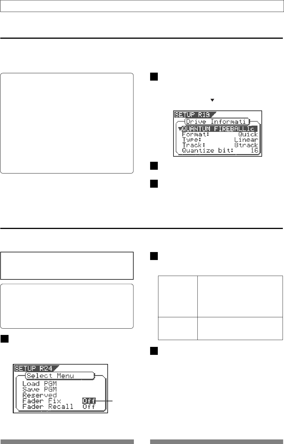
132
SETUP mode
Select the desired item with the [JOG] dial and press
the [ENTER/YES] key.
The selected item will be set.
Fader Fix Mode Setting [“Fader Fix”]
Whether the fader manipulation should be reflected on the sound volume or not can be set.
The setup content will be held even if the main power is switched off.
Select “Fader Fix” in the menu selection display and
press the [ENTER/YES] key.
The currently set will flash. “Off” will flash in the initial
setting.
On For all modes, manipulation of the
Track fader/Master fader will
have not affect on the sound volume.
Any accidental shifting of the fader
position by vibration and
misoperation can be prevented.
Off (Initial setting) Manipulation of the Track fader/
Master fader will affect the sound
volume.
Press the [EXIT/NO] key (or [STOP] key) to exit from the
SETUP mode.
• Initial setting: [Off]
• Options: [On] or [Off]
* You can set the value for each Program individually.
* The settings can be saved and loaded as part of the
song data.
* The settings are maintained after you turn off the
power to the VF80.
flashing
<Caution>
The “Fader Fix Mode” can be made to function when set
in other (Track, Master or Trk & Mst) than “Off” of the
next item on the “Fader Recall Mode”.
1
2
3
The Drive Format Information [“Drive Information”]
Select “Drive Information” in the menu selection display
and press the [ENTER/YES] key.
It will change to the "Drive Information" second level
and the current drive information currently in use
will be displayed (The symbol indicates there is data
below).
As the [JOG] dial is rotated, information will be displayed
one by one.
Press the [EXIT/NO] key (or [STOP] key) to exit from the
SETUP mode.
Format information of the current drive currently installed can be checked by using the “Drive Format
Information” menu. Should any trouble occur in the VF80, providing the information obtained here to our
nearest Fostex Service Station will be of great help in giving quick service.
The following items will be displayed and can be confirmed.
1. Manufacture / Model of the currently installed hard
disk.
2. Format method
3. Format type
4. Simultaneously recordable number of tracks
5. Number of bits at formatting
6. Sampling frequency at formatting
7. Present number of programs
8. Present number of free blocks
9. Audio file / maximum number of events and its
program No.
10. Specific capacity of the drive
11. Remaining capacity of the drive
12. Present software version
1
2
3
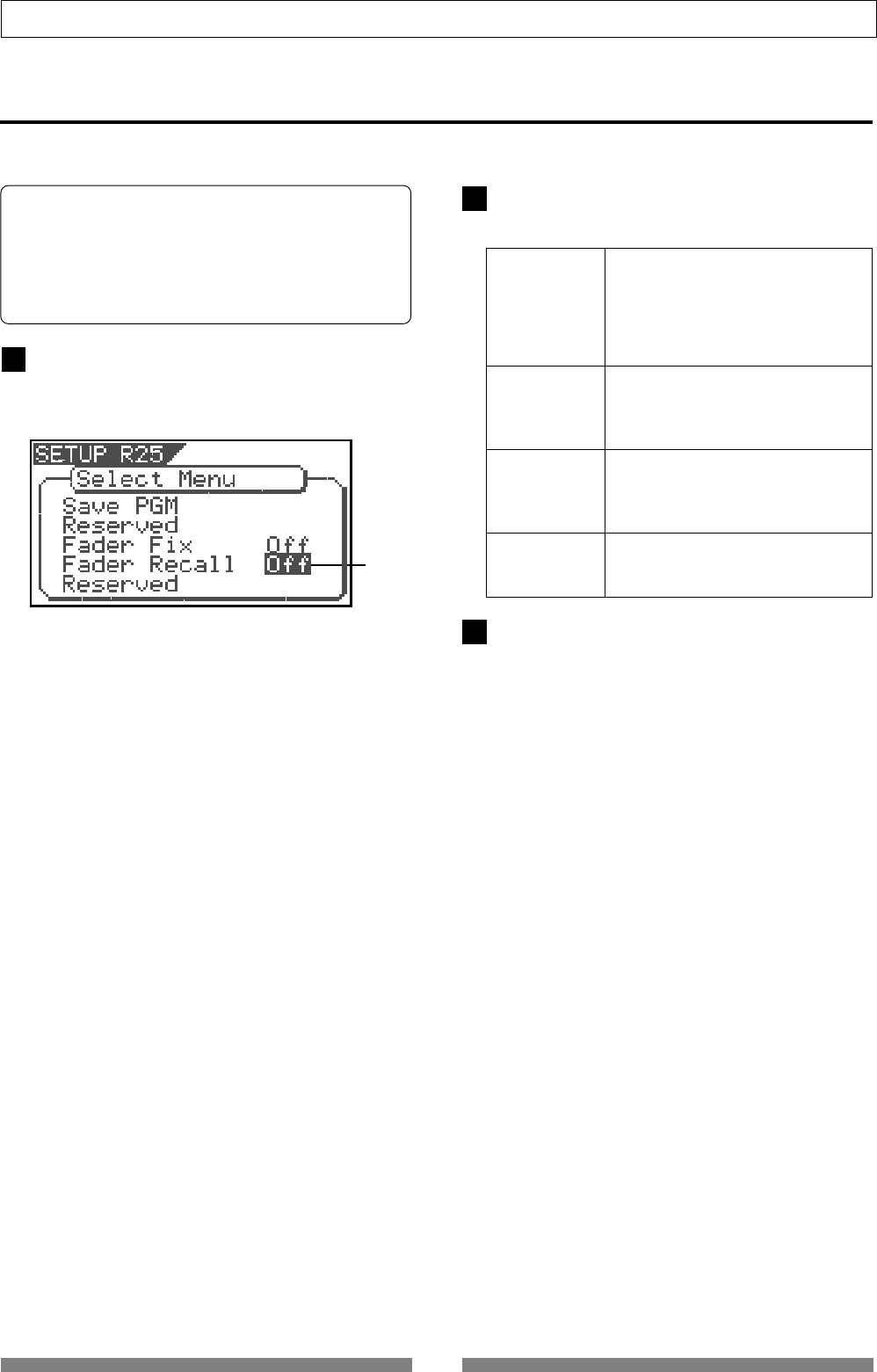
133
SETUP mode
Input the desired item with the [JOG] dial and press
the [ENTER/YES] key.
The selected item will be set.
Fader Recall Mode Setting [“Fader Recall”]
In the "Setup of the fader recall mode" menu, whether each track fader/master fader settings should be
recalled or not at scene recall, can be setup.
Select “Fader Recall” in the menu a selection display
and press the [ENTER/YES] key.
The currently set will flash. “Off” will flash in the
initial setting.
Off When scene is recalled, the fader
(Initial setting) position immediately prior to
recalling the scene will be directly
employed without recalling the
setup figures of each track fader and
the master fader.
Track When scene is recalled, setup figures
of each track faders only will be
recalled and not recall the master
fader setup figure.
Master When scene is recalled, the setup
figure of the master fader only is
recalled and the track fader setup
figures will not be recalled.
Trk & Mst When scene is recalled, each track
faders and the master fader set up
figures will both be recalled.
Press the [EXIT/NO] key (or [STOP] key) to exit from the
SETUP mode.
• Initial setting: [Off]
• Options: [Off], [Track], [Master] or [Trk & Mst]
* You can set the value for each Program individually.
* The settings can be saved and loaded as part of the
song data.
* The settings are maintained after you turn off the
power to the VF80.
flashing
1
2
3
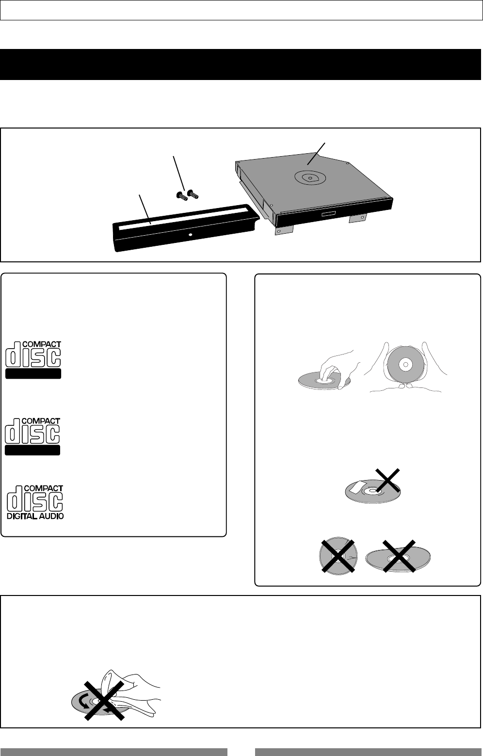
134
Appendix (Installing the optional CD-RW drive)
*a blank panel
*two screws for mounting the drive
*a CD-RW drive unit
Installing the CD-1A
<Usable discs>
With the CD-1A, you can use discs of following
types.
Recordable
ReWritable
<CD-R discs>
Can be used for saving or loading song
data, as well as making an audio CD.
Note that you can record data to a CD-
R disc only once. You cannot record
data to a disc which has been recorded
before.
<CD-RW discs>
Can be used for saving or loading song
data, as well as making an audio CD.
You can record or erase data to a CD-
R disc as many times as wish.
<Audio CD discs>
As these are read-only discs, you only
can use them for loading track data
to the VF80.
<Notes on handling of discs>
• When handling a disc, be careful not to dirty or
scratch the surface of the disc.
We recommend that you hold the disc with your
finger on the disc edge and center hole.
• Do not stick any paper, etc. on the label side.
Also do not scratch the label side, which may cause
problems during playback or recording. Use only a
felt pen or equivalent for writing any memo on the
label side. Using a ball-point pen, pencil, etc. that
has a hard tip may damage a disc.
• Never use a warped or chipped disc, which may
damage the CD-RW drive.
• If there is a dust, dirt or fingerprints on the disc, which
may cause error in playback or recording, wipe the
disc with a soft, dry cloth or alcohol from the center
out. Never wipe from the outside to center.
• Do not use a cleaner for analog discs or antistatic
spray, as well as volatile solvents such as benzine,
which may damage the disc surface.
• Do not expose any disc to direct sunlight, or leave it
in hot, moist or cold places.
• Read the attached manual packed with the disc be
fore using it.
<Notes on care of disc>
The CD-1A package includes the drive and accessories shown below.
After purchasing the unit, check that all items are included. When installing the CD-1A to the VF80, the blank
panel and two screws are not used.
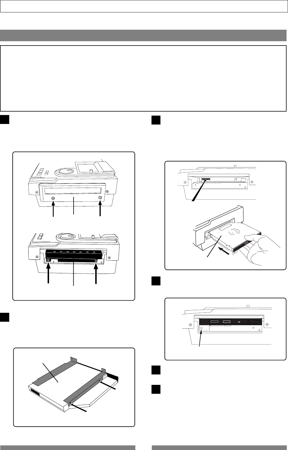
135
Appendix (Installing the optional CD-RW drive)
1
<Notes on installing the CD-RW drive>
• The CD-RW drive is made of precision parts.
Do not apply a mechanical shock or use excessive force when installing it.
• Before installing the drive, make sure that the power of the VF80 is off and the power cord is
disconnected.
• Install the drive correctly according to this manual.
Note that damage to the drive caused by inappropriate installation is not covered by the
guarantee.
How to install the CD-1A
Remove the side cover of the VF80 by unfastening
the two screws using a screw driver.
After removing the cover, remove the blank panel
attached inside the cover.
Retain the cover which will be used later.
2Remove the metal fitting by unfastening the retain-
ing screw (indicated by an arrow) inside the CD-1A.
Because the screw head is small, use a micro screw
driver to carefully unfasten the screw without dam-
aging the head by excessive force.
3Insert the CD-1A unit to the VF80 as shown below.
Carefully insert the CD-1A to the VF80 in the right
direction, without rubbing it against the VF80 cabi-
net. Push the unit carefully and firmly with your
both hands, but without excessive force, until you
feel the connector of the CD-1A mesh with the inter-
nal connector.
4Using the screw (1 pc.) which tightened the blank
panel to VF80, fix CD-1A to the VF80 chassis.
Fasten the screws without excessive force.
Connect the power cable of the VF80 to an AC main
outlet, and turn on the power.
Check that the VF80 starts up and the indicator on
the front panel of the CD-1A flashes for a few sec-
onds and then turns off.
Do not operate the CD-1A unit the VF80 display
shows the Normal screen after showing the start-up
screen.
6
5Fix the cover removed in step 1.
Cover
Blank panel
CD-1A
Connector
Insert the CD-1A
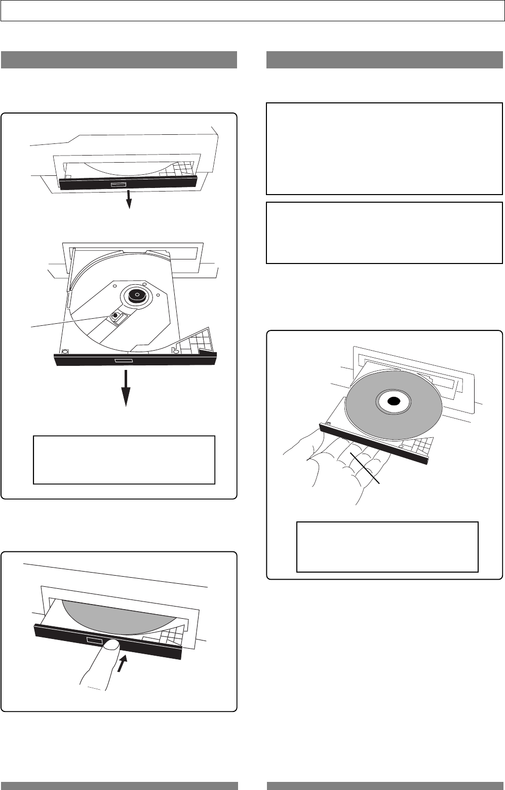
136
Appendix (Installing the optional CD-RW drive)
• To open the tray, press the eject switch lightly.
Pressing the switch will open the tray slightly.
Then pull out the tray gently by hand to fully open it.
Opening/closing the tray
• To close the tray, push the tray inside by hand until locked.
<Caution!>
Do not touch the lens when pulling out
the tray, doing so may damage it and may
cause a malfunction.
<IMPORTANT!>
When placing a disc on the tray, support the tray from
the bottom by your hand. If you push the disc to fit
into the pivot on the tray without supporting the tray,
the tray/drive may be damaged or broken. Also note
that the disc must be pushed until it clicks so that it is
locked into the pivot securely. Closing the tray without
locking the disc may damage the disc.
• Place the disc with the label side up.
When placing the disc, support the tray from the bottom
by your hand as shown in the illustration below, and push
the disc gently until it clicks so that the disc is locked into
the pivot.
<Note for removing a disc from the tray>
When removing a disc from the tray, also support the
tray from the bottom by your hand. Also be careful
not to unlock the disc from the pivot forcibly, which
may damage the tray.
Placing/removing a disc
The following are some notes on placing and/or re-
moving a disc.
<Caution!>
Do not touch the lens when placing a disc,
doing so may damaged may cause a mal-
function.
Lens
Push
Support the tray from the bottom.
Eject
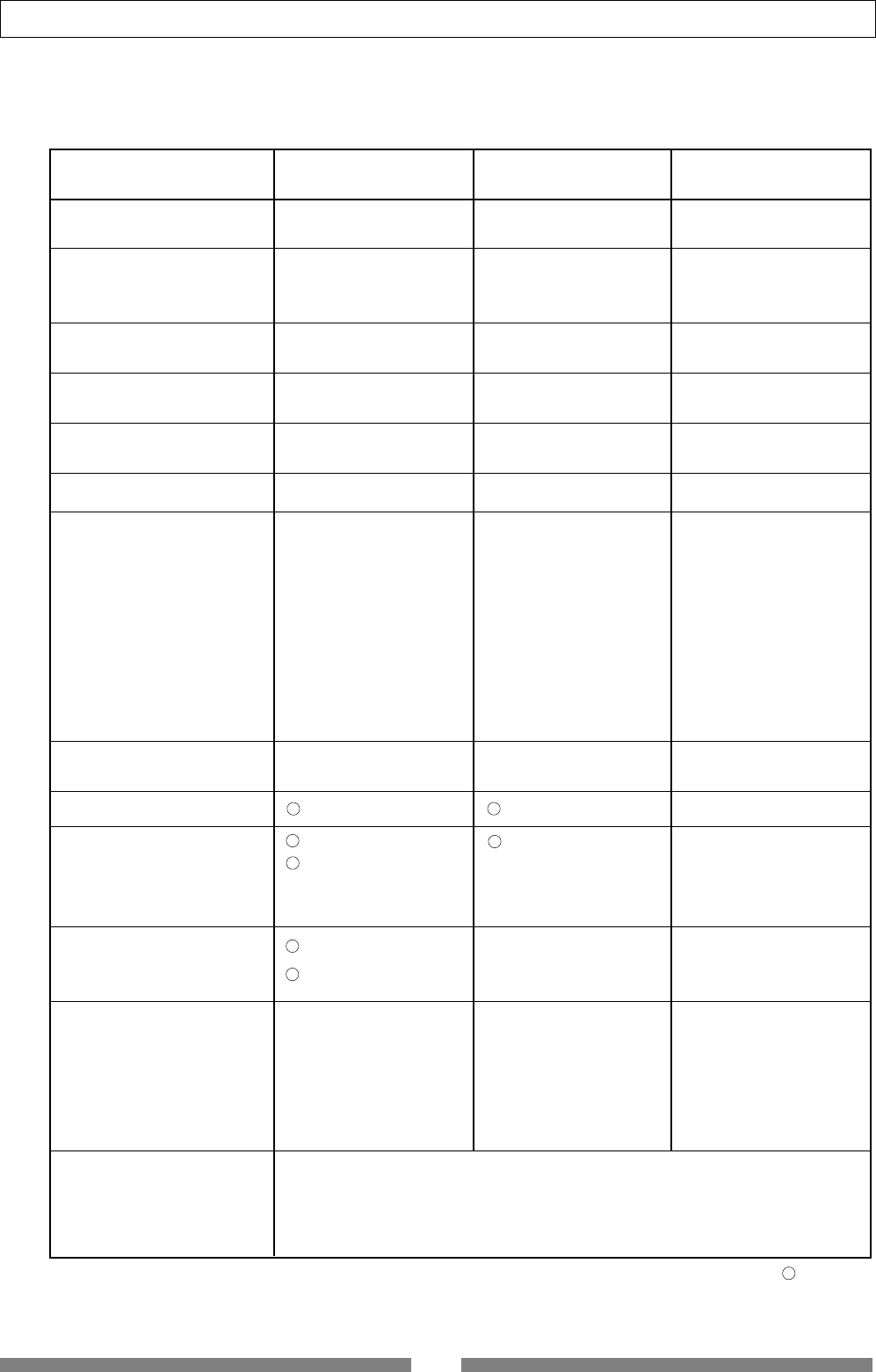
137
Specifications
Basic
Channel
Function....................
Default
Changed
Transmitted Recognized Remarks
Mode
Default
Message
Altered
Note
Number: True Voice
Velocity Note ON
Note OFF
After
Touch
Key’s
Channel’s
Pitch Bend
Control
Change
Program
Change True #
System Exclusive
Common
System
Real Time
: Clock
: Commands
Aux.
Message
: Local ON/OFF
: All Notes OFF
: Reset
: Active Sense
Notes rem.1: MMC (Device ID=00~99, 127), MTC, Identity reply
rem.2: MMC (Device ID=00~99, 127), MTC, Inquiry
Mode 1: OMNI ON, POLY Mode 2: OMNI ON, MONO
Mode 3: OMNI OFF, POLY Mode 4: OMNI OFF, MONO
********************************
********************************
********************************
(rem. 1) (rem. 2)
XX
X
(rem. 3)
X
X
X
X
X
X
X
X
X
X
X
X
X
X
X
X
X
X
X
X
X
X
X
X
X
X
X
X
X
X
X
X
X
X: No
: Yes
Version: V1.00
Date:
Model VF80 MIDI Implementation Chart
(Digital Multitracker)
: Tune
: Song Select
: Song Position
: Quarter Frame
X
X
X
X
X
rem.3: START, STOP, CONTINUE
X
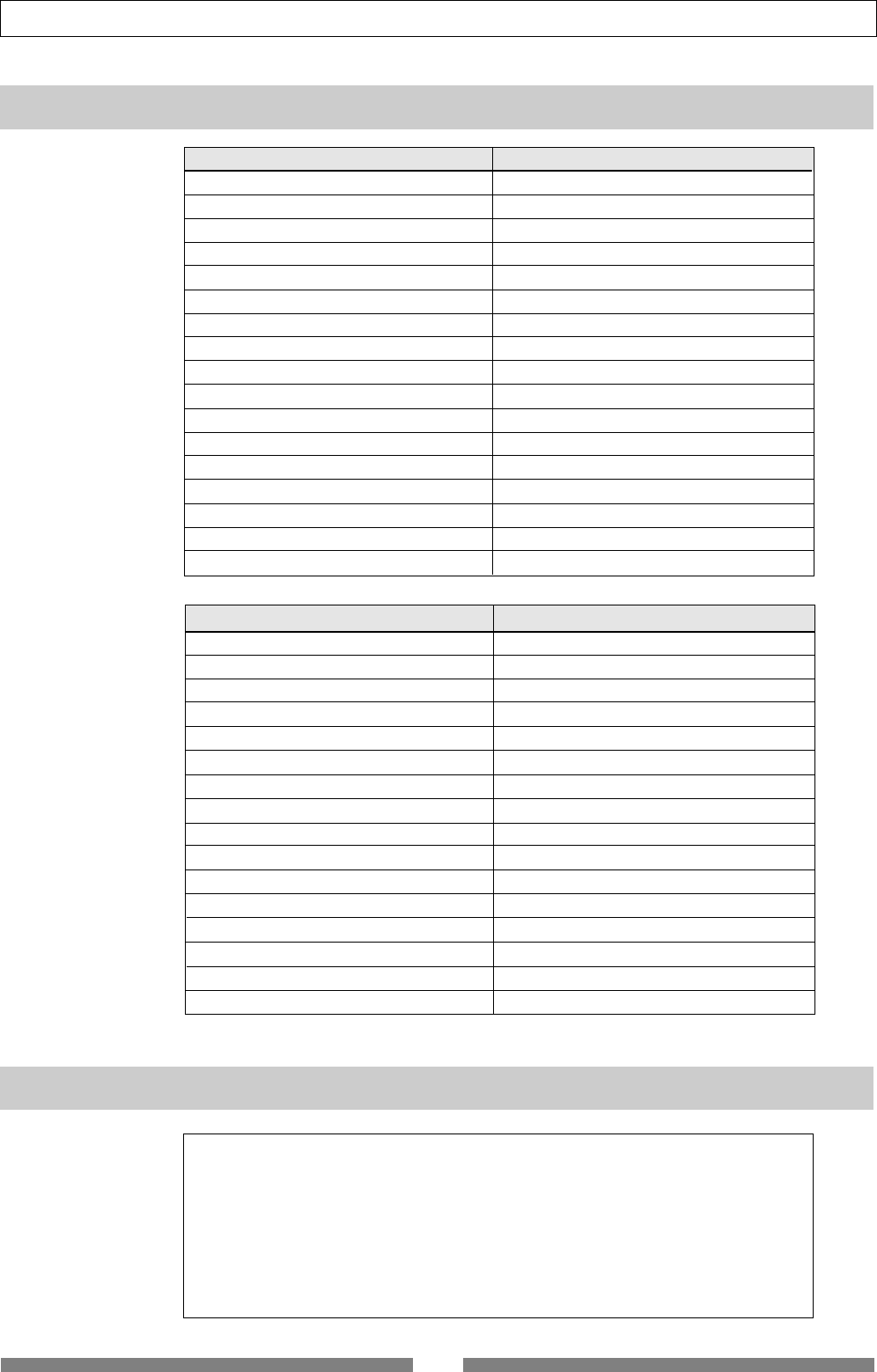
138
Specifications
Command list Movement (Recorder)
01: STOP STOP
02: PLAY PLAY
03: DEFERRED PLAY DEFERRED PLAY
04: FAST FORWARD F FWD
05: REWIND REWIND
06: RECORD STROBE REC
07: RECORD EXIT PUNCH OUT
09: PAUSE STOP
40: WRITE Refer to MMC Response/Information Field List
41: MASKED WRITE Refer to MMC Response/Information Field List
42: READ Refer to MMC Response/Information Field List
44: LOCATE LOCATE to Setting Data
46: SEARCH CUE/REVIEW (+/- 1~60 times)
47: SHUTTLE CUE/REVIEW (+/- 1~60 times)
4C: MOVE Refer to MMC Response/Information Field List
4D: ADD Refer to MMC Response/Information Field List
4E: SUBTRACT Refer to MMC Response/Information Field List
MMC Response/Information Field List Command
01: SELECTED TIME CODE READ/WRITE/MOVE/ADD/SUBTRACT
03: REQUESTED OFFSET READ/WRITE
04: ACTUAL OFFSET READ
08: GP 0 READ/WRITE/MOVE/ADD/SUBTRACT
09: GP 1 READ/WRITE/MOVE/ADD/SUBTRACT
0A: GP 2 READ/WRITE/MOVE/ADD/SUBTRACT
0B: GP 3 READ/WRITE/MOVE/ADD/SUBTRACT
0C: GP 4 READ/WRITE/MOVE/ADD/SUBTRACT
0D: GP 5 READ/WRITE/MOVE/ADD/SUBTRACT
0E: GP 6 READ/WRITE/MOVE/ADD/SUBTRACT
0F: GP 7 READ/WRITE/MOVE/ADD/SUBTRACT
48: MOTION CONTROL TALLY READ
4C: RECORD MODE READ/WRITE
4E: TRACK RECORD STATUS READ
4F: TRACK RECORD READY READ/WRITE/MASKED WRITE
51: RECORD MONITOR READ/WRITE
IDENTITY REQUEST: F0, 7E, <channel>, 06, 01, F7
IDENTITY REPLY: F0, 7E, <channel>, 06, 02, 51, 01, 00, 13, 03, **, **, **, **, F7
51 :Fostex ID
01, 00 :Device family code
13, 03 :Device family number VF80
**, **, **, ** :Software version
MMC Command List
Inquiry Message List

139
Specifications
Maintenance
Specifications
Recording/Reproducing
Recording Medium : 3.5 inch, hard disk (E-IDE type)
Recording Format : FDMS-3 (*)
Save/Load Format : FDIO-1 (**)
Sampling Frequency : 44.1kHz
Quantization : 16-bit linear (Non expanded)
A/D Converter : 20-bit 64 times, over sampling, Delta-Sigma
D/A Converter : 24-bit 128 times, over sampling, Delta-Sigma
No. of Recording Track : 8 real tracks + 16 additional tracks
*2 tracks for simultaneous recording (Maximum)
Vari Pitch Control : +/- 6%
Crossfade : 10msec.
Recording/Reproducing Frequency : 20Hz ~ 20kHz
Input/Output
Input A, B
Connector : ø6mm Phone jack (Unbalanced)
: XLR-3-31 type connector (Balanced)
Input Impedance : 50kΩ or more (Unbalanced)
:1kΩ or more (Balanced)
Standard Input Level : -50 ~ +4dBu
Phantom Power (XLR only) : +48VDC (Setting of ON/OFF with PHANTOM switch)
HEADPHONE
Connector : ø6mm TRS Phone jack
Load Impedance : 10Ω ~ 50Ω
Output Level : 20mW or more (at 32Ω)
STEREO OUT L, R
Connector : ø6mm Phone jack
Load Impedance : 10kΩ or more
Output Level : -10dBV
S/P DIF DIGITAL IN
Connector : COAXIAL
Format : IEC 60958 (S/P DIF)
DIGITAL OUT
Connector : COAXIAL
Format : IEC 60958 (S/P DIF)
MIDI IN/OUT
Connector : DIN 5 PIN
PUNCH IN/OUT
Connector : ø6mm Phone jack (An optional FOOT SW Model 8051
can be connected.)
Cleaning the exterior
* For normal cleaning, use a soft dry cloth.
For stubborn dirt, moisten a cloth in diluted detergent, wring it out firmly, and wipe the dirt off.
Then polish with a dry cloth. Never use solvents such as alcohol, thinner or benzene, since these will
damage the printing and finish of the exterior.
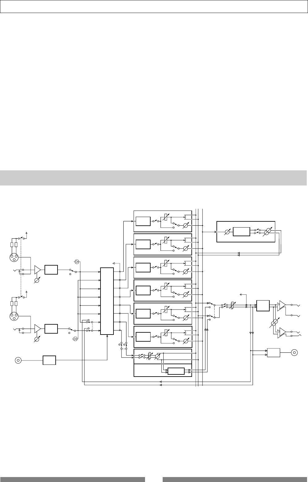
140
Specifications
General
Dimensions : 307 (W) x 108 (H) x 217 (D) mm
Weight : Approx. 3.2kg
Power Supply : 120VAC 60Hz, 230V~ 50/60Hz (AC inlet type)
Power Consumption : 20W
Accessories
: Owner’s manual
: Power Cable
* Fostex Disk Management System-3
** Fostex Data In Out-1
Specifications and appearance are subject to change without notice for product improvement.
Block Diagram
TRK 1
2BAND EQ
MUTE GAIN
PAN
EFFECT
PRE/POST
TRK 2
2BAND EQ
MUTE GAIN
PAN
EFFECT
PRE/POST
TRK 3
2BAND EQ
MUTE GAIN
PAN
EFFECT
PRE/POST
TRK 4
2BAND EQ
MUTE GAIN
PAN
EFFECT
PRE/POST
TRK 5
2BAND EQ
MUTE GAIN
PAN
EFFECT
PRE/POST
TRK 6
2BAND EQ
MUTE GAIN
PAN
EFFECT
PRE/POST
BALANCE
GAIN
MUTE
MASTERING
EFFECT
TRK 7/8
2 TRK
MASTERING
MUTE GAIN
to METER
SEND LEVEL MUTE
ASP
EFFECT
PHONES
DA/C
ST OUT
L
R
DATA OUT
S/P DIF
ENCODE
AD/C
DECODE
AD/C
EFF
LR
to METER
REP 1
REP 2
REP 3
REP 4
REP 5
REP 6
REP 7
REP 8
BOUNCE
REC 8
REC 7
REC 6
REC 5
REC 4
REC 3
REC 2
REC 1
PEAK
PHANTOM (+48V)
TRIM
PHANTOM (+48V)
TRIM
PEAK
S/P DIF
DATA IN
HDR
INPUT A
INPUT B
BOUNCE
ON
OFF
ON
OFF
EFFECT
RTN LEVEL
EFFECT
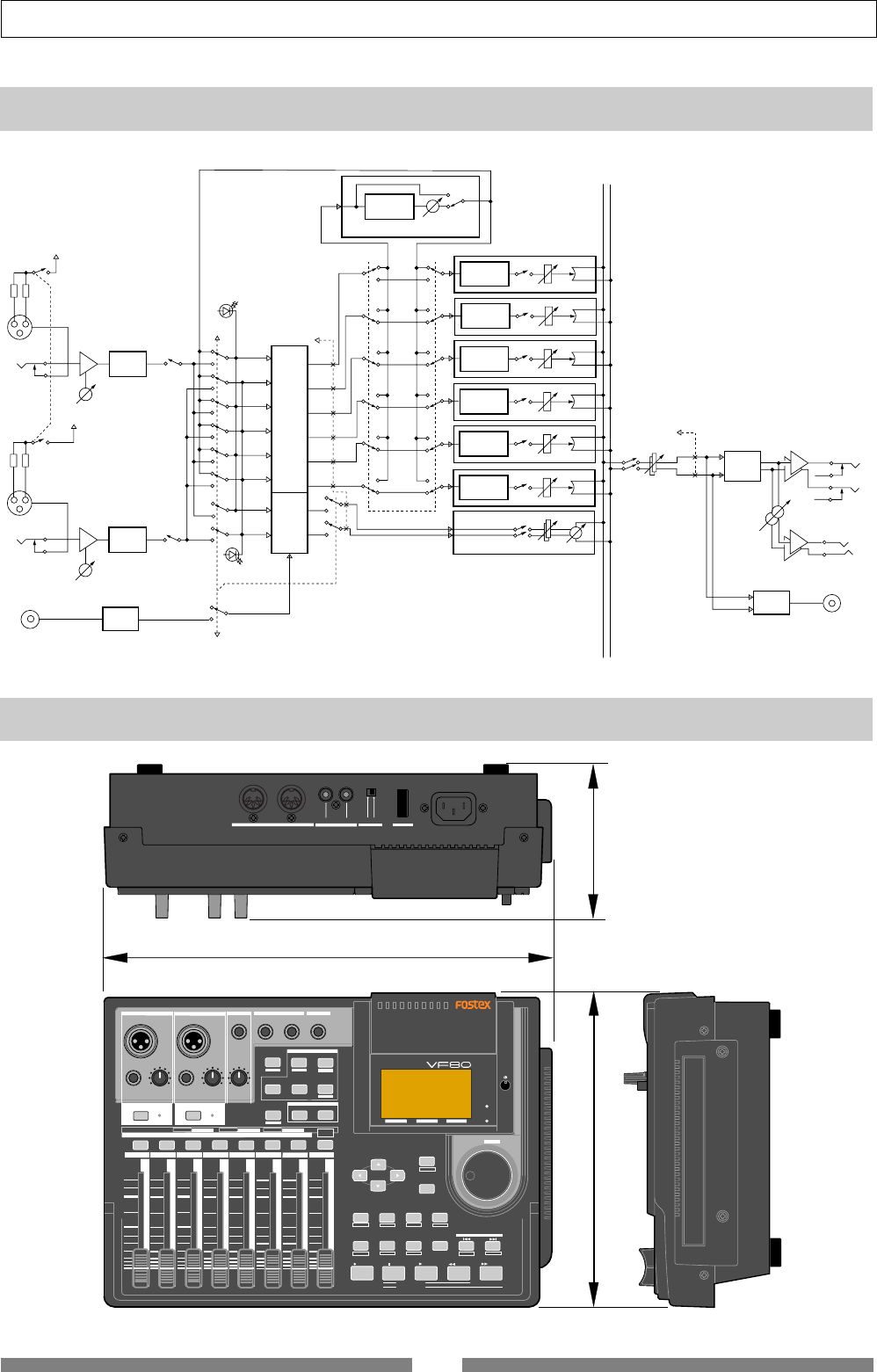
141
Specifications
DIGITAL MULTITRACKER
LOCATE ABS 0
LOCATE REC END
SEL
TIMEBASE
CURSOR
PHANTOM
ACCESS
PEAK
CH ON/OFF
LR
GUITAR
GUITAR
LINE MIC LINE MIC MIN MAX
MASTERING TRAINING
EFFECTEQPAN
SCENE SEQ.SCENE
TRACK
UNDO
SETUP
PUNCH
AUTO LOOP PITCH SCRUB
VARI
F FWDREWINDPLAYSTOPRECORD
EXIT
ENTER
TRIMTRIM
WAVE FORM
MIX PARAMETER
PGM FADER MAP
ON/OFF
2TRK MODE
F1 F2 F3 SHIFT
EDIT EDIT EDIT MARK DELETE
LOCATE
FOOT SW
ST OUT
PHONES
INPUT A
BOUNCE
INPUT B
+6
-10
-20
-40
-
∞
-30
0
+6
-10
-20
-40
-
∞
-30
0
+6
-10
-20
-40
-
∞
-30
0
+6
-10
-20
-40
-
∞
-30
0
+6
-10
-20
-40
-
∞
-30
0
+6
-10
-20
-40
-
∞
-30
0
+6
-10
-20
-40
-
∞
-30
0
+6
-10
-20
-40
-
∞
-30
0
PEAK
CH ON/OFF
2 3 4 5 6 7/8 2TRK1 MASTER
TRACK STATUS / TRACK SEL
TRACK STATUS RED REC GREEN PLAY OFF MUTE STATUS
/SEL
EJECT
/YES
/NO
SHUTTLE
JOG
UNBAL UNBAL
BAL
BAL
F1 F2 F3
EDIT
/REDO
REC EFF
OFF
ON
MIDI
OUTPUT INPUT OUTPUT
INPUT
POWER PHANTOM S/P DIF / DATA
307
108
217
Dimensions
AD/C
CH ON/OFF
TRIM
PHANTOM (+48V)
PEAK
REC EFF
REC 1
REC 2
REC 3
REC 4
REC 5
REC 6
REC 7
REC 8
PEAK
CH ON/OFF
REP 8
REP 7
REP 6
REP 5
REP 4
REP 3
REP 2
REP 1
to METER
TRK 1
MUTE
GAIN
PAN
2BAND EQ
TRK 2
MUTE
GAIN
PAN
2BAND EQ
TRK 3
MUTE
GAIN
PAN
2BAND EQ
TRK 4
MUTE
GAIN
PAN
2BAND EQ
TRK 5
MUTE
GAIN
PAN
2BAND EQ
TRK 6
MUTE
GAIN
PAN
2BAND EQ
TRK 7/8
MUTE GAIN BALANCE
MUTE GAIN
DA/C
PHONES LEVEL
PHONES
ST OUT
L
R
S/P DIF
DATA OUT
ENCODE
to METER
ON/OFF
OUT Level
INSERT
EFFECT
PHANTOM (+48V)
INPUT A
INPUT B
AD/C
TRIM
S/P DIF
DATA IN
DECODE
Normal
Effect Track
LR
Block Diagram (when using the insert effect)

FOSTEX DISTRIBUTORS LIST IN EUROPE
* Including non-EU countries (as of January, 2002).
<ITALY>
NAME: Proel S.p.A.
ADD: Zona Artigianale 64047-Sant’ Omero (Teramo), Italy
TEL: (+39) 0861-81241, FAX: (+39) 0861-887862
<THE NETHERLANDS>
NAME: IEMKE ROOS AUDIO B. V.
ADD: Kuiperbergweg 20, 1101 AG Amsterdam, The
Netherlands
TEL: (+31) 20-697-2121, FAX: (+31) 20-697-4201
<NORWAY>
NAME: Siv. Ing. Benum A/S
ADD: P. O. Box 145 Vinderen, 0319 Oslo 3, Norway
TEL: (+47) 22-139900, FAX: (+47) 22-148259
<PORTUGAL>
NAME: Caius - Tecnologias Audio e Musica, Lda.
ADD: Rua de Santa Catarina, 131 4000 Porto, Portugal
TEL: (+351) 2-2086009/2001394
FAX: (+351) 2-2054760/2087488
<SPAIN>
NAME: Multitracker, S. A.
ADD: C/Garcilaso No.9, Madrid 28010, Spain
TEL: (+34) 91-4470700, 91-4470898, FAX: (+34) 91-5930716
<SWEDEN>
NAME: TTS Scandinavia AB
ADD: Kavallerivagen 24, 172 48 Sundbyberg, Sweden
TEL: (+46) 8-59798000, FAX: (+46) 8-59798001
<SWITZERLAND>
NAME: Audio Bauer Pro AG
ADD: Bernerstrasse-Nord 182, CH-8064 Zurich, Switzerland
TEL: (+41) 1-4323230, FAX: (+41) 1-4326558
<UK>
NAME: SCV London
ADD: 40 Chigwell Lane, Oakwood Hill Industrial Estate,
Loughton, Essex IG10 3NY U.K.
TEL: (+44) 020-8418-0778, FAX: (+44) 020-8418-0624
Declaration of EC Directive
This equipment is compatible with the EMC Directive (89/336/EEC) - Directive on approximation of member
nation's ordinance concerning the electromagnetic compatibility and with the Low Voltage Directive (73/23/EEC)
- Directive on approximation of member nation's ordinance concerning electric equipment designed to be used
within the specified voltage range.
The Affect of Immunity on This Equipment
The affect of the European Specification EN50082-1 (coexistence of electromagnetic waves - common
immunity specification) on this equipment are as shown below.
* In the electrical fast transient/burst requirements, surge, conducted disturbances by radio-frequency fields,
power frequency magnetic field, radiate electromagnetic field requirements and static electricity discharging
environment, this could be affected by generation of noise in some cases.
<AUSTRIA>
NAME: ATEC Audio-u. Videogeraete VertriebsgesmbH.
ADD: Im Winkel 5, A-2325 Velm, Austria
TEL: (+43) 2234-74004, FAX: (+43) 2234-74074
<BELGIUM>
NAME: EML Sound Industries NV
ADD: Bijvennestraat 1A, B3500 Hasselt, Belgium
TEL: (+32) 11-232355, FAX: (+32) 11-232172
<DENMARK>
NAME: SC Sound ApS
ADD: Malervej 2, DK-2630 Taastrup, Denmark
TEL: (+45) 4399-8877, FAX: (+45) 4399-8077
<FINLAND>
NAME: Noretron Oy Audio
ADD: P. O. Box 22, FIN-02631 Espoo, Finland
TEL: (+358) 9-5259330, FAX: (+358) 9-52593352
<FRANCE>
NAME: Guillard Musiques
ADD: ZAC de Folliouses, B. P. 609, Les Echets, 01706 Miribel,
France
TEL: (+33) 472 26 27 00, FAX: (+33) 472 26 27 01
<GERMANY>
NAME: Studiosound & Music GmbH
ADD: Industriestrasse 20, D-35041 Marburg, F. R. Germany
TEL: (+49) 6421-92510, FAX: (+49) 6421-925119
<GREECE>
NAME: Bon Studio S. A.
ADD: 6 Zaimi Street, Exarchia, 106.83 Athens, Greece
TEL: (+30) 1-3809605-8, 3302059, FAX: (+30) 1-3845755
<ICELAND>
NAME: I. D. elrf. electronic Ltd.
ADD: ARMULA 38 108 REYKJAVIK, ICELAND
TEL: (+354) 588 5010, FAX: (+354) 588 5011

FOSTEX CORPORATION
3-2-35, Musashino, Akishima-shi, Tokyo, Japan 196-0021
FOSTEX AMERICA
15431, Blackburn Ave., Norwalk, CA 90650, U. S. A.
© PRINTED IN JAPAN JAN. 2002 8588 011 000 FX
356698
