Franklin Technology S600 3G/4G USB Adapter User Manual S600 manul 20110331
Franklin Technology Inc. 3G/4G USB Adapter S600 manul 20110331
Users Manual

1
S600 User Manual

2
FCC Regulations:
zThis device complies with part 15 of the FCC Rules. Operation is subject to the following
two conditions: (1) This device may not cause harmful interference, and (2) this device must
accept any interference received, including interference that may cause undesired operation.
zThis device has been tested and found to comply with the limits for a Class B digital device,
pursuant to Part 15 of the FCC Rules. These limits are designed to provide reasonable
protection against harmful interference in a residential installation. This equipment generates,
uses and can radiated radio frequency energy and, if not installed and used in accordance
with the instructions, may cause harmful interference to radio communications. However,
there is no guarantee that interference will not occur in a particular installation If this
equipment does cause harmful interference to radio or television reception, which can be
determined by turning the equipment off and on, the user is encouraged to try to correct the
interference by one or more of the following measures:
-Reorient or relocate the receiving antenna.
-Increase the separation between the equipment and receiver.
-Connect the equipment into an outlet on a circuit different from that to which the receiver is
connected.
-Consult the dealer or an experienced radio/TV technician for help.
Changes or modifications not expressly approved by the party responsible for compliance
could void the user‘s authority to operate the equipment.
zThe antenna(s) used for this transmitter must not be co-located or operating in conjunction
with any other antenna or transmitter.
4RF Exposure Information
This device meets the government’s requirements for exposure to radio waves.
This device is designed and manufactured not to exceed the emission limits for exposure to
radio frequency (RF) energy set by the Federal Communications Commission of the U.S.
Government.
zThis device complies with FCC radiation exposure limits set forth for an uncontrolled
environment. In order to avoid the possibility of exceeding the FCC radio frequency exposure
limits, human proximity to the antenna shall not be less than 20cm (8 inches) during normal
operation.
I. Functions and Usage

3
The S600 development Kit is used to debug the Franklin Wireless M600 series module. It is designed by
an auxiliary board with Franklin Wireless M600 series module embedded. When the S600 is used, you can
connect the module to a PC through a USB cable. When the module works normally, the debugging
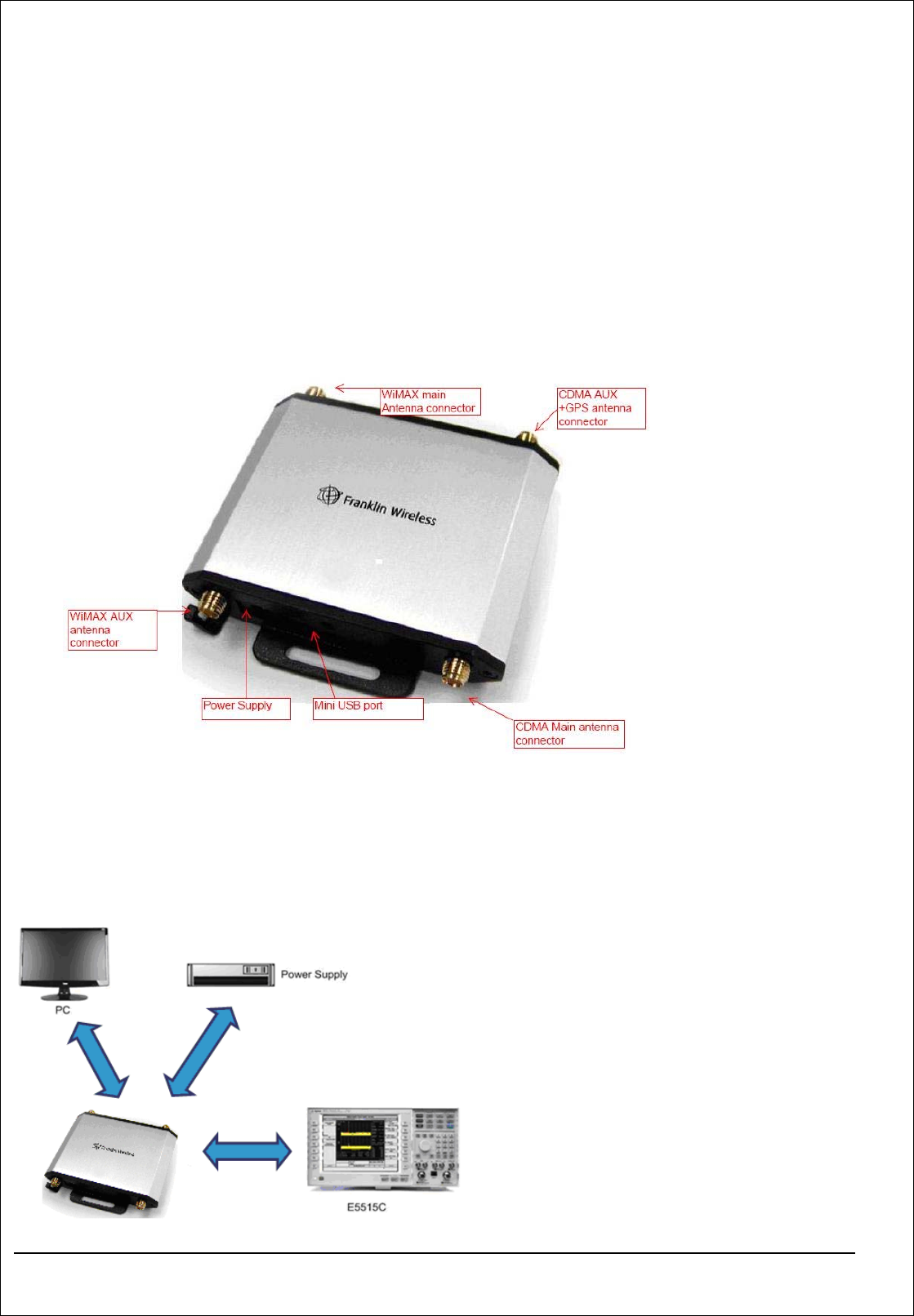
functions can be implemented. The S600 provides multiple interfaces, such as the Mini-USB port, DC
power jack, RF connectors.
The S600 can be used to test the performance of the module. Both the wired connection test (connect the
module to the each equipment) and the wireless connection test (connect the module to the antennas) can
be implemented. The signal points can also be tested when you maintain and repair the module.
II. Structure
Figure-1 Structure of the S600
III. Method for Connecting the S600
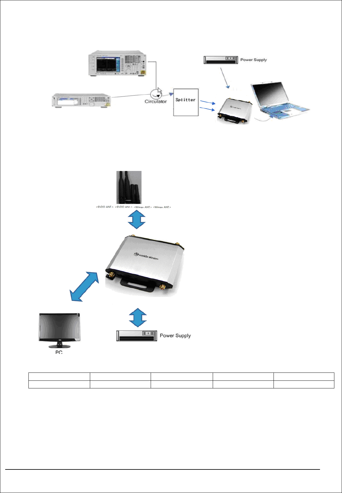
1. Diagram of connecting the S600 to the equipment.
Figure-2. Configuration for Adjustment and Test of CDMA, PCS mode

4
Figure-3. Configuration for Adjustment and Test of WIMAX mode
2. Diagram of connecting the S600 and the antenna
Figure-4. Diagram of connecting the module and the antenna
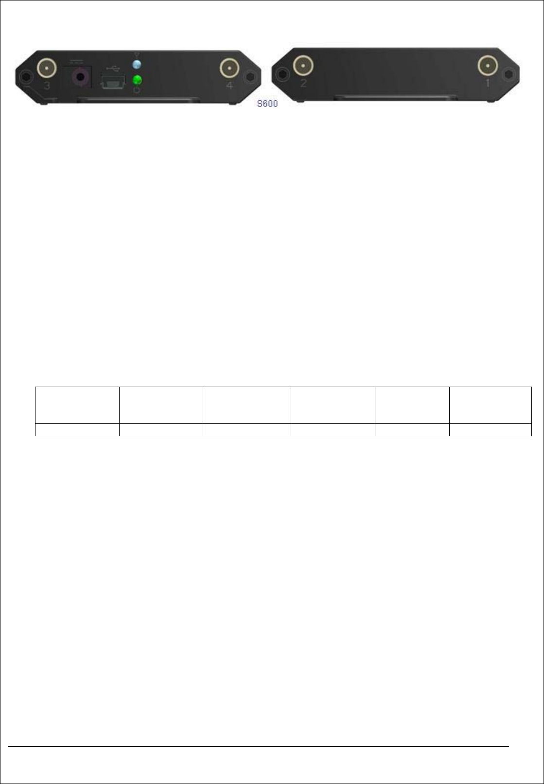
Table-1. Port definition of RF connectors
Port definition 1 2 3 4
S600 WiMAX Main CDMA Aux+GPS WiMAX Aux CDMA Main
Figure -5 Port definition of RF connectors

5
IV. Installation of the S600
z Connect the devices and set up the test environment according to Figure-2 or Figure-3. Then
connect the S600 to the PC through a Micro-USB to Type A USB cable..
z When performing the wired connection test, connect the E5515C to the RF interface of the S600..
(For the connection method, see Figure-2 and Figure-3)
z When performing the wireless connection test, connect the antennas to the RF interface of the
S600 directly. (For the connection method, see Figure-4.)
V. LED indication of the S600
Green: H/W power indication
Blue: Indicate the state of the card.(M600)
VI. Material List
Model Device USB Y-Cable CDMA Main
antenna CDMA
Aux/GPS
antenna
WiMAX
antenna
S600 1 EA 1 EA 1 EA 1 EA 2 EA