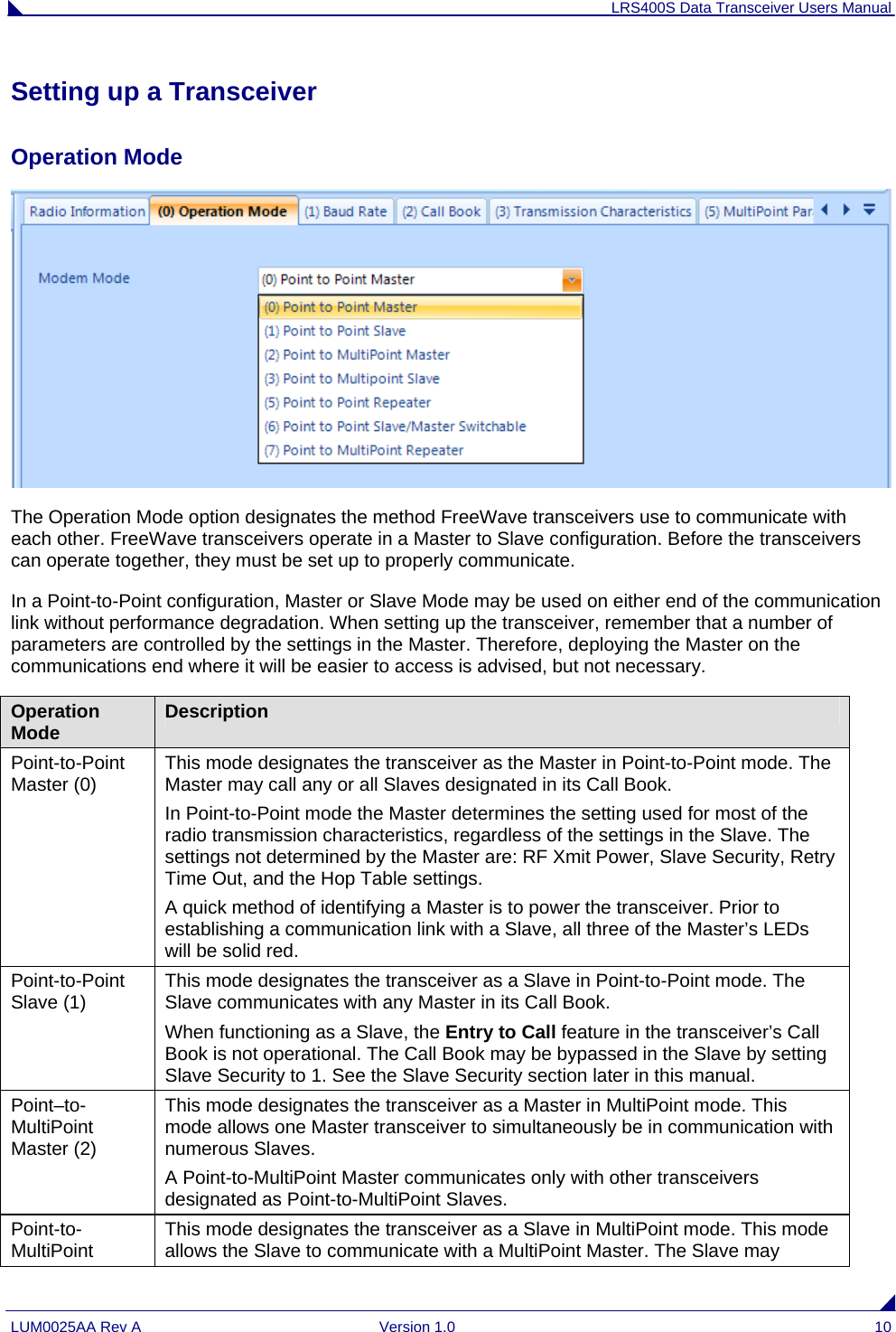
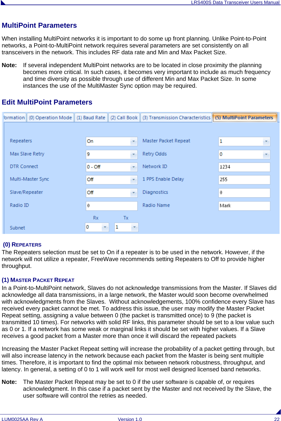
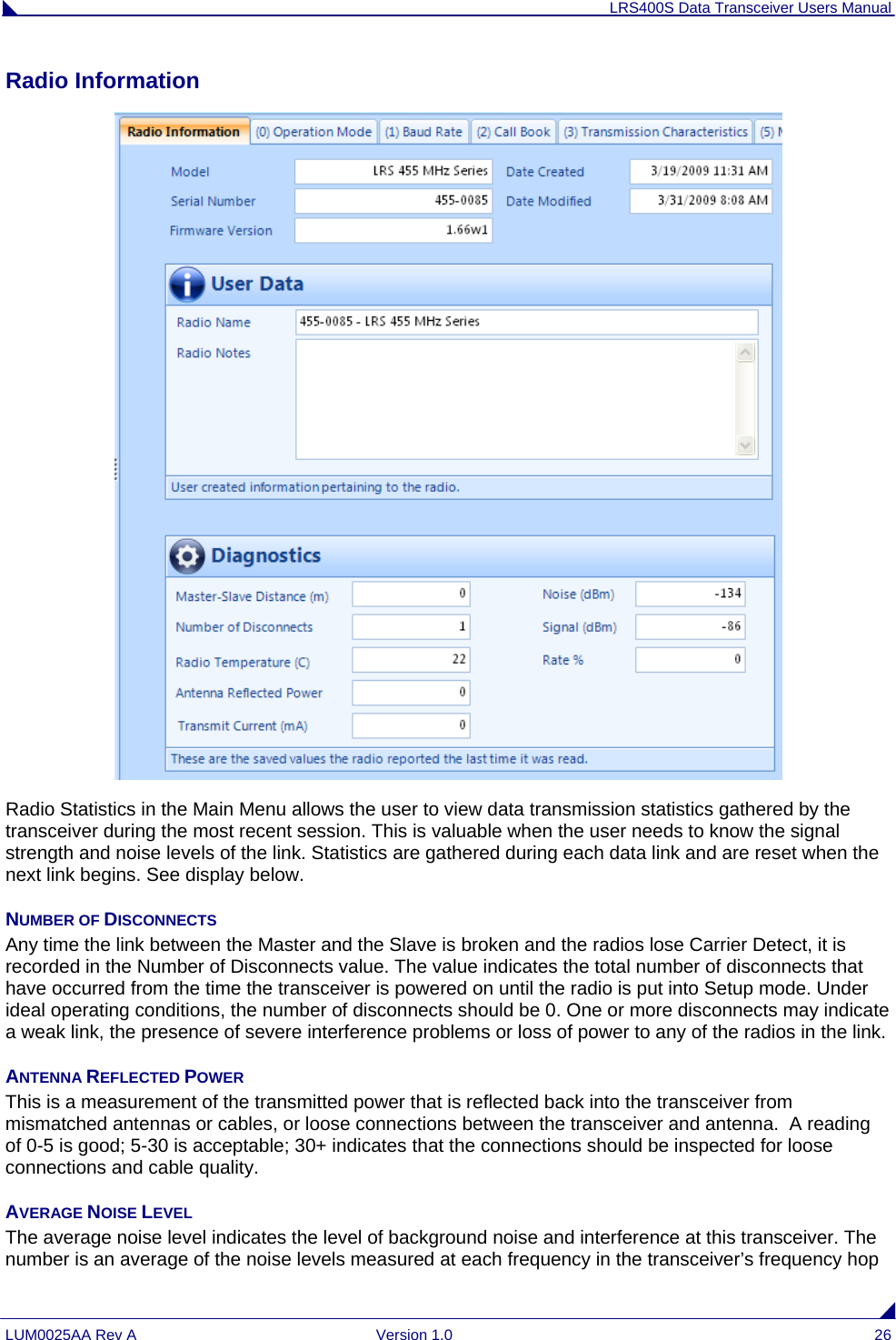
FreeWave Technologies 1293514195135 406.1-430MHz, 2 W, Licensed Radio System User Manual Exhibit D Users Manual per 2 1033 c3

FreeWave Technologies Inc. 406.1-430MHz, 2 W, Licensed Radio System Exhibit D Users Manual per 2 1033 c3

Exhibit D Users Manual per 2 1033 c3

LRS400S Data Transceiver Manual LUM0025AA Rev A  Version 1.0  i          FreeWave Technologies LRS400S Data Transceiver Version 1.0        FreeWave Technologies, Inc. 1880 South Flatiron Court Boulder, CO 80301 (303) 444-9200 (303) 786-9948 Fax www.FreeWave.com
LRS400S Data Transceiver Users Manual LUM0025AA Rev A  Version 1.0  ii LICENSED BAND WIRELESS DATA TRANSCEIVER USER MANUAL  Copyright © 1995-2010 by FreeWave Technologies, Inc. All rights reserved. Published 2010. WARRANTY FreeWave Technologies warrants your FreeWave® Wireless Data Transceiver against defects in materials and manufacturing for a period of two years from the date of shipment.  In the event of a Product failure due to materials or workmanship, FreeWave will, at its option, repair or replace the Product.  The Product must be returned to FreeWave upon receiving a Return Material Authorization (RMA) for evaluation of Warranty Coverage. In no event will FreeWave Technologies Inc., its suppliers, and its licensors be liable for any damages arising from the use of or inability to use this Product.  This includes business interruption, loss of business information, or other loss which may arise from the use of this Product.  Please be advised that OEM customer’s warranty periods may vary. Warranty Policy may not apply: 1.  If Product repair, adjustments or parts replacements is required due to accident, neglect, unusual physical, electrical or electromagnetic stress. 2.  If Product is used outside of FreeWave specifications. 3.  If Product has been modified, repaired or altered by Customer unless FreeWave specifically authorized such alterations in each instance in writing.  This includes the addition of conformal coating.   Special Rate Replacement Option  A special rate replacement option is offered to non-warranty returns or upgrades.  The option to purchase the replacement unit at this special rate is only valid for that RMA.  The special replacement rate option expires if not exercised within 30 days of final disposition of RMA. RESTRICTED RIGHTS Any product names mentioned in this manual may be trademarks, or registered trademarks of their respective companies and are hereby acknowledged. Information in this manual is subject to change without notice and is proprietary and confidential to FreeWave Technologies, Inc. This manual is for use by purchasers and other authorized users of the FreeWave® Wireless Data Transceiver only.  No part of this manual may be reproduced or transmitted in any form or by any means, electronic or mechanical, or for any purpose without the express written permission of FreeWave Technologies, Inc. FreeWave’s Wireless Data Transceivers are designed and manufactured in the United States of America. Printed in the United States of America.
LRS400S Data Transceiver Users Manual LUM0025AA Rev A  Version 1.0  iii CAUTION:   The LRS400S series transceiver have maximum transmitted output power of 2W. It is recommended that the transmit antenna be kept at least 71 cm away from nearby persons to satisfy FCC RF exposure requirements.
LRS400S Data Transceiver Users Manual LUM0025AA Rev A  Version 1.0  iv Table of Contents ABOUT FREEWAVE TRANSCEIVERS.................................................................................................................6 CHOOSING A LOCATION FOR THE TRANSCEIVERS....................................................................................6 CHOOSING POINT-TO-POINT OR POINT-TO-MULTIPOINT OPERATION ........................................................................7 QUICK START ON A POINT-TO-MULTIPOINT NETWORK ..........................................................................8 POINT-TO-MULTIPOINT OPERATION LEDS. ...............................................................................................................8 QUICK START ON A POINT-TO-POINT NETWORK........................................................................................9 POINT-TO-POINT OPERATION LEDS...........................................................................................................................9 SETTING UP A TRANSCEIVER ...........................................................................................................................10 OPERATION MODE....................................................................................................................................................10 BAUD RATE..............................................................................................................................................................12 CALL BOOK..............................................................................................................................................................15 RADIO TRANSMISSION CHARACTERISTICS ...............................................................................................................16 EDIT RADIO TRANSMISSION CHARACTERISTICS .......................................................................................................16 Setting Xmit and Rcv Frequencies.......................................................................................................................16 (1) and (2) Max Packet Size and Min Packet Size...............................................................................................17 (3) Xmit Rate........................................................................................................................................................18 (4) RF Data Rate .................................................................................................................................................18 (5)RF Xmit Power................................................................................................................................................18 (6) Slave Security.................................................................................................................................................19 (7) RTS to CTS.....................................................................................................................................................19 (8) Retry Time Out...............................................................................................................................................19 (9) Lowpower Mode.............................................................................................................................................20 (C) Remote LED ..................................................................................................................................................21 MULTIPOINT PARAMETERS ......................................................................................................................................22 EDIT MULTIPOINT PARAMETERS..............................................................................................................................22 (0) Repeaters........................................................................................................................................................22 (1) Master Packet Repeat ....................................................................................................................................22 (2) Max Slave Retry .............................................................................................................................................23 (3) Retry Odds .....................................................................................................................................................23 (4) DTR Connect..................................................................................................................................................23 (6) Network ID.....................................................................................................................................................23 (8) MultiMaster Sync...........................................................................................................................................23 (9) 1 PPS Enable/Delay.......................................................................................................................................23 (A) Slave/Repeater...............................................................................................................................................24 (B) Diagnostics....................................................................................................................................................24 (C) Subnet ID.......................................................................................................................................................24 (D) Radio ID........................................................................................................................................................25 (E) Local Access ..................................................................................................................................................25 (G) Radio Name...................................................................................................................................................25 RADIO INFORMATION ...............................................................................................................................................26 Number of Disconnects........................................................................................................................................26 Antenna Reflected Power.....................................................................................................................................26 Average Noise Level ............................................................................................................................................26 Average Signal Level...........................................................................................................................................27 Overall Rcv Rate (%)...........................................................................................................................................27 Radio Temperature..............................................................................................................................................27 FACTORY DEFAULT SETTINGS.........................................................................................................................28 OPERATIONAL RS-422 AND RS-485 INFORMATION .................................................................................................29 RS-422 and RS-485 Full Duplex Pin-Outs ..........................................................................................................30
LRS400S Data Transceiver Users Manual LUM0025AA Rev A  Version 1.0  v RS-485 Half Duplex Pin-Outs..............................................................................................................................30 RS232 PIN ASSIGNMENTS ........................................................................................................................................30 RF BOARD PINOUT...................................................................................................................................................31 FREEWAVE TECHNICAL SUPPORT ............................................................................................................................31
LRS400S Data Transceiver Users Manual LUM0025AA Rev A  Version 1.0  6 About FreeWave Transceivers FreeWave transceivers operate in virtually any environment where RS232 data communications occur. A pair of transceivers function as a 9-pin null modem cable. If the FreeWave transceivers are to be used in an application where a null modem cable is used, such as communication between two computers, then the FreeWave transceivers can be connected directly. If FreeWave transceivers are to be used to replace a straight-through RS232 cable, then a null modem cable must be placed between the transceiver and the DTE instrument to which it is connected.  Choosing a Location for the Transceivers Placement of the FreeWave transceiver is likely to have a significant impact on its performance. The key to the overall robustness of the radio link is the height of the antenna. In general, FreeWave units with a higher antenna placement will have a better communication link. In practice, the transceiver should be placed away from computers, telephones, answering machines and other similar equipment. The RS232 cable included with the transceiver usually provides ample distance for placement away from other equipment. To improve the data link, FreeWave Technologies offers directional antennas with cable lengths ranging from 3 to 200 feet. When using an external antenna, placement of that antenna is critical to a solid data link. Other antennas in close proximity are a potential source of interference; use the Radio Statistics to help identify potential problems. The Show Radio Statistics page is found in option 4 in the Main Menu.  An adjustment as little as 2 feet in antenna placement can resolve some noise problems. In extreme cases, band pass filter may reduce the out-of-band noise.
LRS400S Data Transceiver Users Manual LUM0025AA Rev A  Version 1.0  7 Choosing Point-to-Point or Point-to-MultiPoint Operation A Point-to-Point network is limited to one Master and one Slave transceiver.   In a Point-to-MultiPoint network (also referred to as MultiPoint network) the transceiver, designated as a Master, is able to simultaneously communicate with numerous Slaves. In its simplest form, a MultiPoint network functions with the Master broadcasting its messages to all Slaves and the Slaves responding to the Master when given data by the device connected to the data port. It is important to note the differences between Point-to-Point and MultiPoint networks. In a Point-to-Point network all packets are acknowledged, whether sent from the Master to the Slave or from the Slave to the Master. In a MultiPoint network, outbound packets from the Master to Slaves are sent a set number of times determined by the user.  The receiving transceiver will accept the first packet received that passes the 32 bit CRC. However, the packet is not acknowledged. On the return trip to the Master, all packets sent by the Slave are acknowledged or retransmitted until they are acknowledged. Therefore, the return link in a MultiPoint network is generally very robust. Note: In licensed band operation it is suggested to set the repeated master packets at 0 due to the spectrum being quiet. This will maximize throughput and leverage the advantages of licensed band operation. Traditionally, a MultiPoint network is used in applications where data is collected from many instruments and reported back to one central site. As such, the architecture of such a network is different from Point-to-Point applications. The number of radios in a MultiPoint network is influenced by the following parameters: 1.  Size of the blocks of data. The longer the data blocks, the smaller the network capacity. 2.  Baud rate. 3.  The amount of contention between Slaves. Polled Slaves vs. timed Slaves.   For example, if the network will be polling Slaves once a day to retrieve sparse data, several hundred Slaves could be configured to a single Master. However, if each Slave will be transmitting data at greater levels, then fewer Slaves should be linked to the Master.  The overall network will be closer to capacity with fewer Slaves. For examples and additional information on data communication links, see the section Examples of Data Communication Links later in this document.
LRS400S Data Transceiver Users Manual LUM0025AA Rev A  Version 1.0  8 Quick Start on a Point-to-MultiPoint Network The following is a quick start guide for setting up two transceivers in Point-to-MultiPoint mode.  This mode allows for a Master to communicate with several Slaves simultaneously.  1.  Connect the transceiver to the serial port of a computer either through a serial cable or via the diagnostics cable. Make sure to connect the radio to a power source (typically, 6 to 30 VDC). 2.  Open up a HyperTerminal session. •  Use the following settings in connecting with HyperTerminal •  Connect to COMx (where 'x' is the number of the com port being connected to) •  Set data rate to - 19,200, data bits - 8, Parity- none, Stop bits – 1, Flow control – none.   3. Press the Setup button on the radio.  If using the diagnostics cable, press Shift-U (capital U). •  The three lights on the board should all turn green, indicating Setup mode. •  The main menu will appear on the screen.  4. Press 0 to get into the Operation Mode menu. • Press 2 to set the radio as a point to MultiPoint Master. • OR, Press 3 to set the radio as a point to MultiPoint Slave. • Press Esc to get back to Main menu.  5. Press 1 in the main menu to change the Baud Rate. •  The baud rate must be changed to match the baud rate of the device that the radio is to be attached to.   • Press Esc to get back to Main menu.  6.  At the Main Menu, press 3.  •  Set FreqKey, Max Packet Size, Min Packet Size, RF Data rate identical on all radios in the network.  Note:  Changing these values may help to eliminate interference from other FreeWave networks. • Press Esc to get back to Main menu.  7.  At the Main Menu, press 5. •  Set the Network ID value to any value between 1 and 4095, except 255. •  Make sure this value is the same on every radio in the network. Point-to-MultiPoint Operation LEDs.   Master Slave Condition  Carrier Detect (CD)  Transmit (TX)  Clear to  Send (CTS)  Carrier Detect (CD) Transmit (TX)  Clear to Send (CTS) Powered, not linked  Solid red bright Solid red dim Off  Solid red bright Off  Blinking red Slave linked to Master, no data  Solid red bright Solid red dim Off  Solid green Off   * Solid red bright Slave linked to Master, Master sending data to Slave Solid red bright Solid red dim Off  Solid green Off   * Solid red bright Slave linked to Master, Slave sending data to Master Solid green RCV data or Solid red bright Solid red dim Intermittent flash redÑoÒ Solid green Intermittent flash redÑoÒ * Solid red bright Master with diagnostics program running  Solid red bright Solid red dim Intermittent flash redÑoÒ Solid green Intermittent flash redÑoÒ * Solid red bright * Clear to Send LED will be solid red with a solid link, as the link weakens the Clear to Send LED light on the Slave will begin to flash\.
LRS400S Data Transceiver Users Manual LUM0025AA Rev A  Version 1.0  9 Quick Start on a Point-to-Point Network When purchased as a pair, the FreeWave® Wireless Data Transceivers are shipped from the factory pre-configured to operate in Point-to-Point applications.  To establish communications between a pair of FreeWave Wireless Data Transceivers just received from the factory: 1.  Connect antennas to the transceivers. Freewave Technologies recommends that the antenna port be loaded at all times to prevent damage to the LRS400S radios. Noise potential may be reduced on the bench by lowering the Xmit power. 2.  Connect the transceiver to the instrument with the RS232 cable and also attach power.  The cable supplied with enclosed transceivers (except Waterproof) is a 9-pin male serial; professional board level transceivers will need a separate programming cable (sold separately). 3.  Set the Modem mode in each transceiver.  One should be set as a Point-to-Point Master (Mode 0) and the other set as a Point-to-Point Slave (Mode 1). 4.  Set the baud rate on each transceiver to match the baud rate of the instrument to which it is attached. Please note, when setting the transceiver's baud rate, its RS232 data rate is set.  The baud rate does not have to be on the same setting for the two transceivers. 5.  Edit the Call Book.  Enter the Slave serial number in the Master’s Call Book. Enter the Master’s Serial number in the Slave’s Call Book, or disable Slave Security (in the Slave). 6.  Shortly after both transceivers are plugged in, they should establish a communications link with each other and the connection is complete.  Using the table below, verify that the radios are operating as expected. Point-to-Point Operation LEDs  Master Slave Condition  Carrier Detect (CD) Transmit  (TX)  Clear to  Send (CTS)  Carrier Detect (CD)  Transmit (TX)  Clear to  Send (CTS) Powered,  no link  Solid red bright  Solid red bright Solid red bright Solid red bright Off  Blinking red \ Linked, sending sparse data  Solid green Intermittent flash redÑoÒ Intermittent flash redÑoÒ Solid green Intermittent flash redÑoÒ Intermittent flash redÑoÒ Master calling Slave   Solid red bright Solid red dim Solid red bright Solid red bright Off  Blinking red \ Mode 6 - waiting for ATD command  Solid red bright Off  Blinking red\ Solid red bright Off  Blinking red \ Setup Mode  Solid green Solid green Solid green Solid green Solid green Solid green
LRS400S Data Transceiver Users Manual LUM0025AA Rev A  Version 1.0  10 Setting up a Transceiver Operation Mode  The Operation Mode option designates the method FreeWave transceivers use to communicate with each other. FreeWave transceivers operate in a Master to Slave configuration. Before the transceivers can operate together, they must be set up to properly communicate.  In a Point-to-Point configuration, Master or Slave Mode may be used on either end of the communication link without performance degradation. When setting up the transceiver, remember that a number of parameters are controlled by the settings in the Master. Therefore, deploying the Master on the communications end where it will be easier to access is advised, but not necessary. Operation Mode  Description Point-to-Point Master (0)  This mode designates the transceiver as the Master in Point-to-Point mode. The Master may call any or all Slaves designated in its Call Book.  In Point-to-Point mode the Master determines the setting used for most of the radio transmission characteristics, regardless of the settings in the Slave. The settings not determined by the Master are: RF Xmit Power, Slave Security, Retry Time Out, and the Hop Table settings. A quick method of identifying a Master is to power the transceiver. Prior to establishing a communication link with a Slave, all three of the Master’s LEDs will be solid red. Point-to-Point Slave (1)  This mode designates the transceiver as a Slave in Point-to-Point mode. The Slave communicates with any Master in its Call Book. When functioning as a Slave, the Entry to Call feature in the transceiver’s Call Book is not operational. The Call Book may be bypassed in the Slave by setting Slave Security to 1. See the Slave Security section later in this manual. Point–to-MultiPoint Master (2) This mode designates the transceiver as a Master in MultiPoint mode. This mode allows one Master transceiver to simultaneously be in communication with numerous Slaves. A Point-to-MultiPoint Master communicates only with other transceivers designated as Point-to-MultiPoint Slaves. Point-to- MultiPoint  This mode designates the transceiver as a Slave in MultiPoint mode. This mode allows the Slave to communicate with a MultiPoint Master. The Slave may
LRS400S Data Transceiver Users Manual LUM0025AA Rev A  Version 1.0  11 Slave (3)  communicate with its Master. Point-to-Point Repeater (5)  FreeWave allows the use of one repeater in a Point-to-Point communications link, significantly extending the operating range. When designated as a Repeater, a transceiver behaves as a pass-through link. All settings for the call book, baud rates and radio transmission characteristics are disabled. A Repeater will connect with any Master that calls it.  The Repeater must be set up properly in the Master's call book. Point-to-Point Slave/Master Switchable (6) Mode 6 allows the transceiver to be controlled entirely through software commands. A number of key parameters in FreeWave's user interface may be changed either directly with a program such as Windows Terminal or through the use of script files. Additionally, when the Point-to-Point Slave/Master Switchable option is selected and the transceiver is not calling a Slave, it will function as a Slave and accept any appropriate calls from other transceivers. Point-to- MultiPoint Repeater (7) This option allows the transceiver to operate as a Repeater in a MultiPoint network.  See the MultiPoint parameters section for details on enabling MultiPoint Slave/Repeater mode. Note: The use of repeaters in Point to Multipoint Networks is restricted to one repeater per network.
LRS400S Data Transceiver Users Manual LUM0025AA Rev A  Version 1.0  12 Baud Rate This setting is the communication rate between the transceiver and the instrument to which it is connected. It is important to note that this is independent of the baud rate for the other transceiver(s) in the network. For example, a pair of transceivers may be used in an application to send data from remote process instrumentation to an engineer's computer. In this application, the baud rate for the transceiver on the instrumentation might be set to 9600, and the transceiver on the engineer’s computer might be set to 57,600. Set Baud Rate     1. Select the appropriate baud rate to match the attached device.
LRS400S Data Transceiver Users Manual LUM0025AA Rev A  Version 1.0  13 Baud Rate  Description Actual Baud Rate (selections 0-9)  The actual baud rate for the transceiver’s data port.  It is desirable to set the baud rate to the highest level supported by the device to which it is connected.  In certain circumstances, however, this may actually result in slower data communications. Data, Parity   There are six data word length and parity configurations available to be used with FreeWave transceivers. The default setting is 0 (8, N, 1) and is the most commonly used serial communications protocol. Select the appropriate option to communicate with the end device. Data Bits           Parity  Stop Bits  8  None  1  7  Even  1  7  Odd  1  8  None  2  8  Even  1  8  Odd  1 Modbus RTU  Support for Modbus RTU protocol is available. The default setting for Modbus RTU is 0 (Not Enabled). To enable Modbus capability, set Modbus RTU to 1. Note:  When using the transceiver in Modbus RTU mode, the Master Packet Repeat must be set the same in all radios whether the network is in Point-to-Point orMultiPoint mode. The Modbus RTU mode must be selected when transceivers are configured in RS485 or RS422 mode. Serial Interface  In products for which the protocol of the data port is software selectable, use this menu to set the protocol of the data port. In the TTL RF board product this setting must be "0".  Protocol Additional Information RS232               Also used for TTL transceivers. RS422               Modbus RTU mode must be enabled. See above. RS485               Modbus RTU mode must be enabled. See above. DOT                  Special for the Department of Transportation.  Note:    When DOT mode is enabled, the TimeDelay settings operate the same as in the RS485/422 mode. Note: RS4xx mode must have Modbus RTU enabled, and TurnoffDelay set to at least 4. Setup Port  Note: DO NOT change this setting unless the correct programming cable is available for the new setting.   This setting determines which port, Main or Diagnostics, is used to enter the Setup Main Menu.     Port                     Additional Information Main Only             The terminal is connected to the Main Data Port.                       Diagnostics Only   The terminal is connected to the Diagnostic Port.
LRS400S Data Transceiver Users Manual LUM0025AA Rev A  Version 1.0  14 Both Ports           The terminal may be connected to either port. Setup mode is invoked by sending a "U" (capital) to the Diagnostics port or by pressing/toggling the Set-up button/switch, if available.  OEM boards may also enter Setup when Pin 2 is grounded.   The Main Data Port is the RS232 port.  The OEM modules use a 2-row, 2 mm female connector. The diagnostic cable for this port (ASC2009DC) is available from FreeWave. TurnOn/OffDelay  TurnOnDelay- Sets the delay between when the line drivers are turned on and when the data leaves the data port.  This setting can be adjusted for a 1-9 mS delay. TurnOffDelay- This setting specifies the time after the end of transmission of a character to the RS485 bus that the transceiver stops driving the bus and releases the bus to other devices. The units are ¼ of a character with a range of 0-9. An entry of 4 means a delay equivalent to the duration of a full character.  Default is zero delay. For data rates of 1200 bits/S or slower, avoid setting the TurnoffDelay parameter higher than 4.  At those rates the functionality of the microprocessor changes so that a TurnoffDelay of 5 will have the same effect as if set to 1, and a setting of 6 will have the same effect as 2, and so on. Note: TurnOffDelay must be set to a value of at least 4 for RS4xx operation. FlowControl   This menu specifies the hardware flow control for the Data port. The options for 0-3 are described below.  Port                 Additional Information  None                Default - Uses software control (XON XOFF)  RTS    DTR    DOT
LRS400S Data Transceiver Users Manual LUM0025AA Rev A  Version 1.0  15 Call Book   The Call Book is required to be used in Point-to-Point networks. The instructions provided in this section are for Point-to-Point mode only.  Using the Call Book offers both security and flexibility in determining how FreeWave transceivers communicate with each other.  Three settings must be made for two FreeWave transceivers to communicate in Point-to-Point mode: 1.  The Master’s serial number must be listed in the Slave's Call Book or Slave Security is turned off in the Slave. 2.  The Slave’s serial number must be listed in the Master's Call Book. 3.  The Master must be programmed to call the Slave. The Call Book allows users to incorporate up to 10 FreeWave transceivers, and designate which Slave the Master will call.  To set the Entry to Call option, select the appropriate option in the drop down.
LRS400S Data Transceiver Users Manual LUM0025AA Rev A  Version 1.0  16 Radio Transmission Characteristics The Edit Radio Transmission Characteristics option allows the user to modify several different parameters in the transceiver. Many of these parameters must be maintained throughout the network for proper functionality.  Note:   This menu is only for the sophisticated user who has a good understanding of the principles of radio data transmission.  The settings for the Slave(s) not determined by the Master are RF Xmit Power, Slave Security, Retry Time Out and Hop Table Size, Hop Table Version, and Hop Table Offset.  Note: Above image from LRS455. Configuration will be the same. Edit Radio Transmission Characteristics  SETTING XMIT AND RCV FREQUENCIES  The 400MHz Data Transceiver has the option to operate in a Frequency Division Duplex mode by transmitting on one frequency and receiving on another.  The LRS400S transceivers must be programmed to operate on the appropriate frequency. To program the transceiver for single channel operation, enter the frequency, in Megahertz, into the TX and RX Frequency slots.  If the transceivers are to operate in Frequency Division Duplex, the TX and RX Frequency slots will have different frequencies assigned.
LRS400S Data Transceiver Users Manual LUM0025AA Rev A  Version 1.0  17 (1) AND (2) MAX PACKET SIZE AND MIN PACKET SIZE The Max and Min Packet Size settings and the RF Data Rate determine the number of bytes in the packets. Throughput can be enhanced when packet sizes are optimized.  The following 3 tables provide the information to determine optimum setting values. Minimum Packet Size Definition Min Setting  Min Packet Size 0 0 1 16 2 32 3 48 4 64 5 80 6 96 7 112 8 128 9 144   Maximum Packet Size (2 level FSK) Max Setting  Max Packet Size 0  32 1  48 2  64 3  80 4  96 5  112 6  128 7  135 8  135 9  135  Maximum Packet Size (4 level FSK) Max Setting  Max Packet Size 0  32 1  48 2  64 3  80 4  96 5  112 6  128 7  144 8  160 9  176
LRS400S Data Transceiver Users Manual LUM0025AA Rev A  Version 1.0  18  (3) XMIT RATE FreeWave transceivers utilize a Master Transmit Beacon to provide low current consumption in the slave radios. The slave radios will turn their receiver off when no data is being passed. The Xmit Rate setting allows the duty cycle of the Master Transmit Beacon to be changed. A setting of 0 is the highest duty cycle and a setting of 9 is the lowest duty cycle. (4) RF DATA RATE FreeWave transceivers have five settings for the RF Data Rate (1, 2, 3, 4, 5 ). RF Data Rate should not be confused with the serial port Baud Rate.  Setting 2 should be used when the transceivers are close together and data throughput needs to be optimized. Setting 3 should be used when the transceivers are farther away and a solid data link is preferred over data throughput. Note:   In MultiPoint networks, the RF Data Rate must be set identically in all transceivers. Any transceiver with an RF Data Rate different from the Master will not establish a link.    In Point to Point networks the Master’s settings take precedence over the Slave. RF Data Rate Setting  Occupied Bandwidth  Modulation Level 1 50kHz 2-level GFSK 2 25kHz 4-level GFSK 3 25kHz 2-level GFSK 4 12.5kHz 4-level GFSK 5 12.5kHz 2-level GFSK   (5)RF XMIT POWER The RF Xmit Power parameter allows the user to control the output transmit power up to two watts (+33dBm). Note:  For use in applications requiring greater than 70% transmit duty cycle, the LRS400S series of radios must be attached to an appropriate heat sync. The following table shows RF TX output versus the RF Xmit Power setting. RF Xmit Power  RF TX Power (dBm) RF Xmit Power  RF TX Power (dBm) RF Xmit Power  RF TX Power (dBm) RF Xmit Power  RF TX Power (dBm) 10 +33 7 +30 4 +27 1 +24 9 +32 6 +29 3 +26 0 +23 8 +31 5 +28 2 +25
LRS400S Data Transceiver Users Manual LUM0025AA Rev A  Version 1.0  19 (6) SLAVE SECURITY Slave security is a feature which allows Slave transceivers to accept transmissions from a Master not included in the Call Book. The default setting is 0 (Slave Security enabled) which means, only Masters in the Slaves’ Call Book may link to that Slave.   Slave Security may be disabled (setting of 1) allowing any Master to call the Slave. Slave Security has no effect in Point-to-MultiPoint networks where the Network ID is not set to 255.   Slave Security must be set to 1 when the unit is operating in Mode 6 Slave/Master switchable or a Point-to-Point network where the Slave may need to accept calls from more than 10 different Masters. When Slave Security is set to 1, the transceiver will accept calls from any other FreeWave transceiver. Additional network security measures may be taken to prevent unauthorized access, such as changing default settings for FreqKey, Hop Table or Frequency Zones. (7) RTS TO CTS Menu selection RTS to CTS in the Radio Parameters menu provides the option of allowing the RTS line on the Master transceiver to control the CTS line of the Slave. This pass-through control can be enabled in both Point-to-Point and Point-to-MultiPoint. In MultiPoint networks, the Master RTS line will control all Slaves’ CTS lines. When enabled, the CTS line ceases to function as flow control. It is not recommended to enable this feature when operating at RS-232 speeds above 38.4kB. The default setting of 0 disables this function, where as a setting of 1 enables RTS-CTS control.   RTS-CTS setting 2 is described in detail in the application note #5437 DTR to CTS Line Alarm Feature.  With an RTS to CTS setting of 1, the Master senses the RTS line prior to all scheduled packet transmissions.  If the state has changed, the Master will then transmit a message to the Slave with the new status. This transmission will occur regardless of data being sent.  If data is ready to be sent, the RTS status message will be sent in addition to the data.  In Point-to-Point mode, the Master will continue sending the new status message until it receives an acknowledgment from the Slave. In MultiPoint mode, the Master will repeat the message the number of times equal to the Master Packet Repeat value in the MultiPoint Parameters menu.  Master transmit times are completely asynchronous to the occurrence of any change of the RTS line; the latency time from RTS to CTS is variable.  The Max and Min Packet Size parameters in the Radio Parameter menu determine this duration.  Setting both parameters to their maximum value of 9 will produce a maximum latency time of approximately 21 ms. At the minimum settings for Max and Min Packet Size (0), the time will be approximately 5.9 ms. Please note that this latency can increase significantly if packets are lost between the Master and Slave. In Point-to-MultiPoint mode, there is no absolute guarantee that the state change will be communicated to all Slaves in the unlikely event that all repeated packets from the Master do not get through to all Slaves.   Note:   If DTRConnect is enabled and set to 2, the RTS to CTS feature will not work. Note:   If the DTRConnect is enabled and set to 1, RTS to CTS mode takes precedence over the functionality of the CTS line on the Slave relating to the DTRConnect feature. Note:   The RTS to CTS option is only available in RS232 mode. (8) RETRY TIME OUT The Retry Time Out parameter in a Slave sets the delay the unit will wait before dropping the connection to a Master in MultiPoint mode. The factory default is set at the maximum of 255. The maximum setting means that if 1 packet in 255 is sent successfully from the Master to the Slave, the link will be maintained. The minimum setting is 8. This allows a Slave to drop a connection if less than 1 in 8 consecutive packets is successfully received from the Master.
LRS400S Data Transceiver Users Manual LUM0025AA Rev A  Version 1.0  20 On the other hand, the function in the Master is effectively the same.  With a setting of 255, the Master will allow a Slave to stay connected as long as 1 packet in 255 is successfully received at the Master.  The Retry Time Out parameter is useful when a MultiPoint network has a roving Master or Slave(s). As the link gets weaker, a lower setting will allow a poor link to break in search of a stronger one. Note:   Setting Retry Time Out to 20 is recommended in areas where several FreeWave networks exist. This setting will allow Slaves to drop the connection if the link becomes too weak, while at the same time prevent errant disconnects due to interference from neighboring networks.  While intended primarily for MultiPoint networks, the Retry Time Out parameter may also be modified in Point-to-Point networks. However, the value in Point-to-Point mode should not be set to less than 151. (9) LOWPOWER MODE The Lowpower Mode feature allows a MultiPoint Slave to consume less power. When set to 2 through 31, the transceiver will sleep between slots. For example, at a setting of 2 the transceiver sleeps 1 out of 2 slots; at a setting of 3 the transceiver sleeps 2 out of 3 slots, and so on.   The following table shows the changes at different Lowpower Mode settings. The actual current draw depends on many factors. The table below gives only a qualitative indication of supply current savings. A low number reduces latency and a high number reduces current consumption. Setting  Description 0 Lowpower, disabled 1  LEDs dimmed, transceiver remains awake, transceiver is listening to the Master’s transmissions on every slot, and transceiver’s data port is shut down if the RTS line is deasserted (low). In this case, the transceiver needs to be awakened before it will be able to send data to the Master. 2  LEDs dimmed, transceiver sleeps every other slot 3  LEDs dimmed, transceiver sleeps 2 of 3 slots 4-31  LEDs dimmed, transceiver sleeps the number of slots corresponding to the setting. For example, with a setting of 31 the transceiver sleeps 30 of 31 slots.  IMPORTANT NOTES 1.  Lowpower Mode is used only in MultiPoint Slaves using serial protocol. Power savings occur only when the Slave is linked. There are no power savings when the Slave is transmitting data. Lowpower Mode is of little value when a Slave has a constant, high throughput. MCUSpeed must be set to ‘0’ and RF Data Rate must be set to ‘3’ for Lowpower Mode to operate properly. 2.  To communicate to an RS232 port of a transceiver that is in Lowpower Mode, the RTS line must be held high to wake it up. The transceiver will wake up within approximately 20 milliseconds of when RTS goes high. 3.  If the RTS line on the Slave is held high, the transceiver will remain in normal operation regardless of the Lowpower Mode setting. Once RTS is dropped the transceiver reverts to the Lowpower Mode.  If the transceiver has the DTRConnect option set to 1 or 2 and if the Lowpower Mode enabled (set to 1-31), the RTS line on the transceiver must be asserted for the ‘DTRConnect’ feature to operate properly.  Current Draw More Less
LRS400S Data Transceiver Users Manual LUM0025AA Rev A  Version 1.0  21 (C) REMOTE LED This setting enables the user to connect Remote LED’s through the diagnostics port.   Setting  Description  Notes 0  Board LED’s  Default. Only on board LEDs are enabled.  1  Board and Remote LED’s  Onboard LED’s are enabled as well as Remote LED’s through the Diagnostic port. 2 Remote LED’s On board LED’s are disabled. Remote LED’s are enabled through the Diagnostic port. Note: When using Remote LED’s the center (TX) LED will not turn Green when in Setup mode. This line is not pinned out.
LRS400S Data Transceiver Users Manual LUM0025AA Rev A  Version 1.0  22 MultiPoint Parameters                                                                                                                   When installing MultiPoint networks it is important to do some up front planning. Unlike Point-to-Point networks, a Point-to-MultiPoint network requires several parameters are set consistently on all transceivers in the network. This includes RF data rate and Min and Max Packet Size. Note:   If several independent MultiPoint networks are to be located in close proximity the planning becomes more critical. In such cases, it becomes very important to include as much frequency and time diversity as possible through use of different Min and Max Packet Size. In some instances the use of the MultiMaster Sync option may be required.  Edit MultiPoint Parameters    (0) REPEATERS The Repeaters selection must be set to On if a repeater is to be used in the network. However, if the network will not utilize a repeater, FreeWave recommends setting Repeaters to Off to provide higher throughput. (1) MASTER PACKET REPEAT    In a Point-to-MultiPoint network, Slaves do not acknowledge transmissions from the Master. If Slaves did acknowledge all data transmissions, in a large network, the Master would soon become overwhelmed with acknowledgments from the Slaves.  Without acknowledgements, 100% confidence every Slave has received every packet cannot be met. To address this issue, the user may modify the Master Packet Repeat setting, assigning a value between 0 (the packet is transmitted once) to 9 (the packet is transmitted 10 times). For networks with solid RF links, this parameter should be set to a low value such as 0 or 1. If a network has some weak or marginal links it should be set with higher values. If a Slave receives a good packet from a Master more than once it will discard the repeated packets Increasing the Master Packet Repeat setting will increase the probability of a packet getting through, but will also increase latency in the network because each packet from the Master is being sent multiple times. Therefore, it is important to find the optimal mix between network robustness, throughput, and latency. In general, a setting of 0 to 1 will work well for most well designed licensed band networks. Note:  The Master Packet Repeat may be set to 0 if the user software is capable of, or requires acknowledgment. In this case if a packet sent by the Master and not received by the Slave, the user software will control the retries as needed.
LRS400S Data Transceiver Users Manual LUM0025AA Rev A  Version 1.0  23 (2) MAX SLAVE RETRY The Max Slave Retry setting defines how many times (0 to 9) the Slave will attempt to retransmit a packet to the Master before beginning to use a back-off algorithm (defined by the Retry Odds setting). Slave retries will stop when an acknowledgement is received from the Master. (3) RETRY ODDS While packets transmitted from the Master to the Slaves in a MultiPoint network are not acknowledged, packets transmitted from Slaves to the Master are. It is possible, that more than one Slave will attempt to transmit to the Master at the same time. Therefore, it is important that a protocol exists to resolve contention for the Master between Slaves. This is addressed through parameters (2) Max Slave Retry and (3) Retry Odds. Once the Slave has unsuccessfully attempted to transmit the packet the number of times specified in Max Slave Retry, it will attempt to transmit to the Master on a random basis. The Retry Odds parameter determines the probability that the Slave will attempt to retransmit the packet to the Master; a low setting will assign low odds to the Slave attempting to transmit.  Conversely, a high setting will assign higher odds. An example of how this parameter might be used would be when considering two different Slaves in a MultiPoint network, one with a strong RF link and the other with a weak RF link to the Master. It may be desirable to assign higher Retry Odds to the Slave with the weaker link to give it a better chance of competing with the closer Slave(s) for the Master's attention. When Retry Odds = 0, after the Slave has exhausted the number of retries set in the Max Slave Retry parameter and still not gained the Master’s attention, the Slave’s data buffer will be purged.   (4) DTR CONNECT With the setting of 0 in the Slave, the transceiver will transmit when RS232 data is received.  A setting of 1 will form a Point-to-Point link with the Master when the DTR line is high.  With a setting of 2, the transceiver will transmit in bursts.  This mode is valuable when a network has many low data rate devices and it is desirable to increase overall network capacity.  Note:  If ‘DTRConnect’ is set to 1 and the ‘RTS to CTS’ function is enabled on the radio, then ‘RTS to CTS’ takes precedence over ‘DTRConnect’.  Note:  If ‘DTRConnect’ is set to ‘2’ and ‘RTS to CTS’ is enabled, then ‘RTS to CTS’ is ignored. The transceiver has two separate transmit and receive user data buffers.  These buffers are 2 Kbytes each.  In case of a buffer overflow, the transceiver will output unpredictable data.  (6) NETWORK ID Network ID allows MultiPoint networks to be established without using the Call Book.  The default setting of 255 enables the Call Book.  To enable Network ID the value must be set between 0 and 4095 (excluding 255).  Since Network ID does not use serial numbers, MultiPoint Masters may be replaced without reprogramming all of the Slaves in the network.  Slaves will link with the first Master that it hears that has a matching Network ID.  The Network ID function should be used in conjunction with the Subnet ID feature (If necessary). Without having the serial numbers in the Call Book, a Slave may establish communications with different Masters, though not at the same time.  This is very useful in mobile MultiPoint applications. (8) MULTIMASTER SYNC MultiMaster Sync is reserved for applications, in both Point-to-Point and MultiPoint modes, with concentrations of Master units where it is necessary to reduce interference between the Masters.  Please contact FreeWave Technologies for more information.  (9) 1 PPS ENABLE/DELAY The 1 PPS Enable/Delay option allows the radio network to propagate a 1PPS signal from the Master to all Slaves in a MultiPoint network. When this parameter is enabled a properly generated pulse applied on
LRS400S Data Transceiver Users Manual LUM0025AA Rev A  Version 1.0  24 the DTR line of the Master will provide a 1 PPS pulse on the CD line of any Slave in the network.  To use the 1 PPS Enable/Delay feature the steps outlined below must be followed: 1PPS Enable/Delay Setup: 1.  The 1 PPS Enable/Delay parameter must be set to 0 in the Master. 2.  The Master must have a 1 PPS pulse on the DTR pin. 3.  The 1 PPS Enable/Delay parameter on the Slaves must be enabled. Slaves are calibrated at the factory. Calibrating a Slave in 1PPS Enable/Delay mode 1. Trigger an oscilloscope on the 1 PPS pulse on the DTR line of the Master. 2. Monitor the CD line of the Slave. 3. If the timing on the Slave differs from the Master it may be adjusted via the value in the Slave's 1 PPS Enable/Delay parameter.  The difference in time between each incremental integer value is 542.534nS.  Changing the parameter to higher values decreases the Slave time delay and changing the parameter to lower values increases the time delay.  When properly calibrated the CD line of a Slave radio will output a pulse that goes high for about 2mS in sync with the 1 PPS pulse on the Master radio.  The output on the Slave will occur within 20 microseconds of the input to the Master. Note:   When 1 PPS is enabled, the Master must have a 1 PPS pulse on its DTR pin, otherwise the RF network will not function. (A) SLAVE/REPEATER Normally a repeater does not have the ability to provide data on the data port. When this capability is necessary Slave/Repeater should be set to On. When using Slave/Repeater, the baud rate and communication protocol must match the end device. (B) DIAGNOSTICS This option provides diagnostics data to be viewed at the Master in parallel with application data.  The diagnostic program MUST be run from the Master transceiver.  Diagnostics requires the following: 1.  Diagnostics set to (1 to 128) in the Master. 2.  A second computer or serial connection to run the diagnostics software. 3.  A diagnostics cable. (Available from FreeWave Technologies.) 4.  Diagnostics software. (Available on the User Manual and System Tools CD.) For more information on Diagnostics, please contact FreeWave Technical Support at (303) 381-9200. (C) SUBNET ID The Subnet ID function only works in MultiPoint Networks utilizing the Network ID option.  In a MultiPoint Network, a Slave or Repeater will connect with the first Repeater or Master that it hears with the same Network ID.  However, where communications need to be forced to follow a specific path the Subnet ID is quite useful.  Subnet ID is particularly helpful to force two Repeaters in the same network to operate in series rather than in parallel, or if desired, to force Slaves to communicate to a specific Repeater for load balancing purposes. Two components exist with regard to the Subnet ID: 1.  Rcv Subnet ID.  This setting identifies which transceiver a Repeater or Slave will listen to.
LRS400S Data Transceiver Users Manual LUM0025AA Rev A  Version 1.0  25 2.  Xmit Subnet ID.  This setting identifies the ID on which this device transmits, and in turn which devices will listen to it. The Xmit Subnet ID parameter is relevant for MultiPoint Repeaters only. The default (disable) setting for both Rcv and Xmit is F. Notes:  A Master will always transmit and receive on 0. Changing these settings on the Master is not recommended, under normal circumstances. In some MultiPoint Networks, the FreqKey will be at the same setting for all transceivers.  In other networks, where parallel Repeaters are introduced, the FreqKey value will need to change.  See FreqKey and Repeater Frequency sections earlier in this manual for more information. If both Rcv Subnet ID and Xmit Subnet ID are set to 0 the Subnet ID will show Roaming in the menu.  This setting will allow a mobile Slave to roam from subnet to subnet and possibly from network to network.   This drawing depicts a Network in which Subnet IDs are used to force communications.  In this example, Repeater1 must talk directly to the Master; Repeater2 must talk directly to Repeater1.  Slaves 1, 2, and 3 are forced along the direction of the solid lines.  Slave4 may link to the first Master or Repeater it hears.  The respective Subnet ID diagram and settings are shown below.                                                            (D) RADIO ID Option (D) allows a transceiver to be designated with an arbitrary, user selectable, 4 digit number which identifies the transceiver in diagnostics mode. (E) LOCAL ACCESS Local Access is not to be used at this time. (G) RADIO NAME Option (G) allows the user to set a unique 20 character Radio name.
LRS400S Data Transceiver Users Manual LUM0025AA Rev A  Version 1.0  26 Radio Information  Radio Statistics in the Main Menu allows the user to view data transmission statistics gathered by the transceiver during the most recent session. This is valuable when the user needs to know the signal strength and noise levels of the link. Statistics are gathered during each data link and are reset when the next link begins. See display below. NUMBER OF DISCONNECTS Any time the link between the Master and the Slave is broken and the radios lose Carrier Detect, it is recorded in the Number of Disconnects value. The value indicates the total number of disconnects that have occurred from the time the transceiver is powered on until the radio is put into Setup mode. Under ideal operating conditions, the number of disconnects should be 0. One or more disconnects may indicate a weak link, the presence of severe interference problems or loss of power to any of the radios in the link. ANTENNA REFLECTED POWER This is a measurement of the transmitted power that is reflected back into the transceiver from mismatched antennas or cables, or loose connections between the transceiver and antenna.  A reading of 0-5 is good; 5-30 is acceptable; 30+ indicates that the connections should be inspected for loose connections and cable quality. AVERAGE NOISE LEVEL The average noise level indicates the level of background noise and interference at this transceiver. The number is an average of the noise levels measured at each frequency in the transceiver’s frequency hop
LRS400S Data Transceiver Users Manual LUM0025AA Rev A  Version 1.0  27 table. The individual measurement values at each frequency hop channel are shown in the frequency table. Pressing the Enter key when the Radio Statistics menu is displayed, accesses the frequency table. Ideally, noise levels should be below -120 dBm units and the difference between the average signal level and average noise level should be 26 dB or more. Noise levels significantly higher than this are an indication of a high level of interference that may degrade the performance of the link.  High noise levels can often be mitigated with band pass filters, antenna placement or antenna polarization.  AVERAGE SIGNAL LEVEL The average signal level indicates the level of received signal at this transceiver. For each of these, the signal source is the transceiver that transmits to it. The number is an average of the received signal levels measured at each frequency in the transceiver's frequency hop table. The individual measurement values at each frequency hop channel are shown in the frequency table. Pressing the Enter key when the Radio Statistics menu is displayed accesses the frequency table. For a reliable link, the margin should be at least 26 dB. Low Average Signal Levels can often be corrected with higher gain antennas and better antenna placement.  Note:  Please consult the install manual for antenna and FCC requirements. OVERALL RCV RATE (%) The Overall Receive Rate measures the percentage of data packets that were successfully transmitted from the Master to the Slave on the first attempt.  A number of 75 or higher indicates a robust link that will provide very good performance even at high data transmission rates. A number of 15 or lower indicates a weak or marginal link that will provide lower data throughput.  RADIO TEMPERATURE The Radio Temperature value is the current operating temperature of the transceiver in degrees Celsius. For proper operation, a FreeWave transceiver must be in the temperature range of -30° to +60° C.
LRS400S Data Transceiver Users Manual LUM0025AA Rev A  Version 1.0  28 Factory Default Settings FreeWave 415MHz transceivers are shipped from the factory with the following Default Settings:  Operation Mode  Default Point to Point Slave  1 Set Baud Rate  Default Baud Rate  19200 (A)  Data Parity  0 (B) Modbus RTU  0 (C) RS232/485  0 (D) Setup Port  3 (E) TurnOffDelay/OnDelay  0/0 (F) Flow Control  0 Radio Parameters   Default   (1)  MAX PACKET SIZE          9  (2)  MIN PACKET SIZE            1  (3)  XMT RATE                     1  (4)  RF DATA RATE                5  (5)  RF XMT POWER          10  (6)  SLAVE SECURITY         0  (7)  RTS TO CTS   0  (8)  RETRY TIMEOUT   255  (9)  LOW POWER MODE   0 (A)  High Noise  0 (B) MCU Speed  0 (C) Remote LED  0 MultiPoint Parameters Default (1)  MASTER PACKET REPEAT  0 (2)  MAX SLAVE RETRY   9 (3)  RETRY ODDS  0 (4)  DTR CONNECT  0 (6)  NETWORK ID    255 (7)  RESERVED    (8)  MULTI MASTER SYNC   0 (9)  1 PPS ENABLE DELAY  255 (B)  DIAGNOSTICS   0 (D)  RADIO ID      Not Set
LRS400S Data Transceiver Users Manual LUM0025AA Rev A  Version 1.0  29 Additional Transceiver information This section contains additional important information about FreeWave transceivers. The following topics are included in this section:   Operational RS422 and RS-485 Information   RS232 Pin Assignments   OEM Board Pin Assignments  Operational RS-422 and RS-485 Information For both RS-422 and RS-485, the FreeWave transceiver can drive 32 standard unit loads and loads the bus with only 1/8 unit load. This means the user can tie up to 256 devices on the bus if all of the line receivers have 1/8 unit load. RS-422 is used for 4-wire or full duplex communication with one Master and multiple Slaves. The FreeWave Master transceiver keeps the line driver asserted at all times. The maximum line length is 4,000 feet using 2, 120 ohm twisted pair cables with a 5th wire for data common. RS-485 full duplex using 4 wire plus common is the same as RS-422, except the system can have multiple Masters on the bus. The most common operation of RS-485 is a two-wire comprised of a 120 ohm impedance single twisted pair. In this system the loading of the FreeWave transceiver is as described above which allows up to 256 1/8 unit load units on the bus. Maximum line length is also 4,000 feet with a third wire required for data common. The FreeWave transceiver will check the line to be certain no other device is transmitting before enabling the line driver for data transmission. When setting the transceiver to RS-485, enable Modbus and set Master Packet Repeat to 3 in the transceiver(s) that will use RS-485. Also set TurnOff Delay to 4. The TurnOffDelay setting in the menu is used to control the length of time the transmitter driver stays asserted after data transmission has finished. This is needed to allow the last transmitted character to reach the end of a long line and is normally set to one character length of time. This setting also allows 3 complete reflections to the end of the line to ensure the ringing on the line has fully dampened before releasing the bus to another device. Shorter line lengths may use shorter delays, but four one-quarter-character delay times are recommended. In Modbus, a TurnOffDelay setting of 0 will cause internal timing errors. There is no provision for hand shaking in any of the above modes of operation, so data rates of 57.6 KBaud and above are not recommended without a protocol that can handle error detection properly.
LRS400S Data Transceiver Users Manual LUM0025AA Rev A  Version 1.0  30  RS-422 AND RS-485 FULL DUPLEX PIN-OUTS Function  Bare Board Pin Number  DE-9 Pin Number RX+ 7  3 RX- 9  7 TX+ 5  2 TX- 10  8 Signal Ground  4 or 6  5 RS-485 HALF DUPLEX PIN-OUTS Function  Bare Board Pin Number  DE-9 Pin Number Wire to both pins for Bus +  Short 5 and 7  Short 2 and 3 Wire to both pins for Bus -  Short 9 and 10  Short 7 and 8 Signal Ground  4 or 6  5  RS232 Pin Assignments Pin   Assignment  Signal  Definition 1  CD  Carrier Detect  Output  Used to show an RF connection between transceivers. 2 TX  Transmit Data  Output Used to transmit data bits serially from the transceivers to the system device. 3 RX  Receive Data  Input  Used to receive data bits serially from the system device connected to the transceivers. 4  DTR  Data Terminal Ready  Input  Used only in transceivers in Point-to-Point Slave/Master switchable mode or for DTR Connect.  5  GND  Ground    Signal return for all signal lines shared with Pin 9. 6  DSR  Data Set Ready  Output  Always high when the radio is powered from the 2.5mm power connector. Indicated power is on to the radio. Also, this pin can be used for +12Volts when powering the transceivers directly through the RS-232 port. Note: This is not used on the OEM module. 7  RTS  Request to Send  Input  The transceiver does not recognize RTS for flow control. RTS is used as a control line in RTS/CTS mode. 8  CTS  Clear to Send  Output  This signal is used to tell the system device connected to the transceiver that the transceiver is ready to receive data. When asserted, the transceiver will accept data, when deasserted the transceiver will not accept data. This should always be used for data rates above 38.4KB or there will be a risk of lost data if an RF link is not very robust. 9  GND  Ground    Signal return for all signal lines shared with Pin 5.
LRS400S Data Transceiver Users Manual LUM0025AA Rev A  Version 1.0  31 RF Board Pinout The LRS400S series transceivers are available in both TTL and RS232 versions. The TTL versions use reverse polarity from standard RS-232 at 0 to 5 Volt levels. All pin descriptions and pin numbering are the same as the RS232 version. The RS232 versions use standard RS232 polarity and voltage levels for all of the RS232 signal lines (DTR, Transmit Data, Receive Data, Carrier Detect, RTS, and Clear to Send) and TTL standard polarity and voltage level for the Interrupt pin. Pin 1: B+ Power input. Pin 2: Interrupt (INT) – Input – A 0 volt level on this pin will switch the radio into Setup mode. Pin  Assignment  Color on ACS3610xx cable 1 B+ input  Red 2  Interrupt (temporarily ground to invoke menu)  Brown 3  Data Terminal Ready (DTR)  Orange 4 Ground  Black 5  Transmit Data (TXD)  Yellow 6 Ground  Black 7  Receive Data (RXD)  Green 8  Carrier Detect (DCD)  Blue 9  Request to Send (RTS)  Violet (purple) 10  Clear to Send (CTS)  Gray  Note:   Pin 1 on the board level transceiver is the pin farthest from the three LEDs and pin 10 is closest to the LEDs.  FreeWave Technical Support For up-to-date troubleshooting information check the Support page at www.FreeWave.com. FreeWave provides Technical Support, Monday through Friday, 8:00 AM to 5:00 PM, Mountain Time (GMT -7) Call us toll-free at 1-800-548-5616 or factory direct after hours at 303-381-9200 or email us at moreinfo@FreeWave.com
LRS400S Data Transceiver Users Manual LUM0025AA Rev A  Version 1.0  32 Frequency List The LRS400S transceivers tune from 406.1MHz to 430MHz with a tuning resolution of 6.25KHz. This gives a total of 3840 available channels. Using the license allowed frequency, the channel number can be determined using the following formula.   Channel number = (FMHz - 390) / .00625 Note: This is an example list. If the required frequency is not listed use the FMHz formula to obtain the appropriate channel number.   Channel # Frequency   Channel # Frequency  Channel # Frequency   Channel # Frequency2576  406.1000    2910  408.1875   3260  410.3750    3610  412.5625 2578  406.1125    2920  408.2500   3270  410.4375    3620  412.6250 2580  406.1250    2930  408.3125   3280  410.5000    3630  412.6875 2590  406.1875    2940  408.3750   3290  410.5625    3640  412.7500 2600  406.2500    2950  408.4375   3300  410.6250    3650  412.8125 2610  406.3125    2960  408.5000   3310  410.6875    3660  412.8750 2620  406.3750    2970  408.5625   3320  410.7500    3670  412.9375 2630  406.4375    2980  408.6250   3330  410.8125    3680  413.0000 2640  406.5000    2990  408.6875   3340  410.8750    3690  413.0625 2650  406.5625    3000  408.7500   3350  410.9375    3700  413.1250 2660  406.6250    3010  408.8125   3360  411.0000    3710  413.1875 2670  406.6875    3020  408.8750   3370  411.0625    3720  413.2500 2680  406.7500    3030  408.9375   3380  411.1250    3730  413.3125 2690  406.8125    3040  409.0000   3390  411.1875    3740  413.3750 2700  406.8750    3050  409.0625   3400  411.2500    3750  413.4375 2710  406.9375    3060  409.1250   3410  411.3125    3760  413.5000 2720  407.0000    3070  409.1875   3420  411.3750    3770  413.5625 2730  407.0625    3080  409.2500   3430  411.4375    3780  413.6250 2740  407.1250    3090  409.3125   3440  411.5000    3790  413.6875 2750  407.1875    3100  409.3750   3450  411.5625    3800  413.7500 2760  407.2500    3110  409.4375   3460  411.6250    3810  413.8125 2770  407.3125    3120  409.5000   3470  411.6875    3820  413.8750 2780  407.3750    3130  409.5625   3480  411.7500    3830  413.9375 2790  407.4375    3140  409.6250   3490  411.8125    3840  414.0000 2800  407.5000    3150  409.6875   3500  411.8750    3850  414.0625 2810  407.5625    3160  409.7500   3510  411.9375    3860  414.1250 2820  407.6250    3170  409.8125   3520  412.0000    3870  414.1875 2830  407.6875    3180  409.8750   3530  412.0625    3880  414.2500 2840  407.7500    3190  409.9375   3540  412.1250    3890  414.3125 2850  407.8125    3200  410.0000   3550  412.1875    3900  414.3750 2860  407.8750    3210  410.0625   3560  412.2500    3910  414.4375 2870  407.9375    3220  410.1250   3570  412.3125    3920  414.5000 2880  408.0000    3230  410.1875   3580  412.3750    3930  414.5625 2890  408.0625    3240  410.2500   3590  412.4375    3940  414.6250 2900  408.1250    3250  410.3125   3600  412.5000    3950  414.6875
LRS400S Data Transceiver Users Manual LUM0025AA Rev A  Version 1.0  33 Channel # Frequency   Channel # Frequency  Channel # Frequency   Channel # Frequency3960  414.7500    4420  417.6250   4880  420.5000    5340  423.3750 3970  414.8125    4430  417.6875   4890  420.5625    5350  423.4375 3980  414.8750    4440  417.7500   4900  420.6250    5360  423.5000 3990  414.9375    4450  417.8125   4910  420.6875    5370  423.5625 4000  415.0000    4460  417.8750   4920  420.7500    5380  423.6250 4010  415.0625    4470  417.9375   4930  420.8125    5390  423.6875 4020  415.1250    4480  418.0000   4940  420.8750    5400  423.7500 4030  415.1875    4490  418.0625   4950  420.9375    5410  423.8125 4040  415.2500    4500  418.1250   4960  421.0000    5420  423.8750 4050  415.3125    4510  418.1875   4970  421.0625    5430  423.9375 4060  415.3750    4520  418.2500   4980  421.1250    5440  424.0000 4070  415.4375    4530  418.3125   4990  421.1875    5450  424.0625 4080  415.5000    4540  418.3750   5000  421.2500    5460  424.1250 4090  415.5625    4550  418.4375   5010  421.3125    5470  424.1875 4100  415.6250    4560  418.5000   5020  421.3750    5480  424.2500 4110  415.6875    4570  418.5625   5030  421.4375    5490  424.3125 4120  415.7500    4580  418.6250   5040  421.5000    5500  424.3750 4130  415.8125    4590  418.6875   5050  421.5625    5510  424.4375 4140  415.8750    4600  418.7500   5060  421.6250    5520  424.5000 4150  415.9375    4610  418.8125   5070  421.6875    5530  424.5625 4160  416.0000    4620  418.8750   5080  421.7500    5540  424.6250 4170  416.0625    4630  418.9375   5090  421.8125    5550  424.6875 4180  416.1250    4640  419.0000   5100  421.8750    5560  424.7500 4190  416.1875    4650  419.0625   5110  421.9375    5570  424.8125 4200  416.2500    4660  419.1250   5120  422.0000    5580  424.8750 4210  416.3125    4670  419.1875   5130  422.0625    5590  424.9375 4220  416.3750    4680  419.2500   5140  422.1250    5600  425.0000 4230  416.4375    4690  419.3125   5150  422.1875    5610  425.0625 4240  416.5000    4700  419.3750   5160  422.2500    5620  425.1250 4250  416.5625    4710  419.4375   5170  422.3125    5630  425.1875 4260  416.6250    4720  419.5000   5180  422.3750    5640  425.2500 4270  416.6875    4730  419.5625   5190  422.4375    5650  425.3125 4280  416.7500    4740  419.6250   5200  422.5000    5660  425.3750 4290  416.8125    4750  419.6875   5210  422.5625    5670  425.4375 4300  416.8750    4760  419.7500   5220  422.6250    5680  425.5000 4310  416.9375    4770  419.8125   5230  422.6875    5690  425.5625 4320  417.0000    4780  419.8750   5240  422.7500    5700  425.6250 4330  417.0625    4790  419.9375   5250  422.8125    5710  425.6875 4340  417.1250    4800  420.0000   5260  422.8750    5720  425.7500 4350  417.1875    4810  420.0625   5270  422.9375    5730  425.8125 4360  417.2500    4820  420.1250   5280  423.0000    5740  425.8750 4370  417.3125    4830  420.1875   5290  423.0625    5750  425.9375 4380  417.3750    4840  420.2500   5300  423.1250    5760  426.0000 4390  417.4375    4850  420.3125   5310  423.1875    5770  426.0625 4400  417.5000    4860  420.3750   5320  423.2500    5780  426.1250 4410  417.5625    4870  420.4375   5330  423.3125    5790  426.1875
LRS400S Data Transceiver Users Manual LUM0025AA Rev A  Version 1.0  34 Channel # Frequency   Channel # Frequency  Channel # Frequency   Channel # Frequency5800 426.2500   5960 427.2500  6120 428.2500   6280 429.2500 5810 426.3125   5970 427.3125  6130 428.3125   6290 429.3125 5820 426.3750   5980 427.3750  6140 428.3750   6300 429.3750 5830 426.4375   5990 427.4375  6150 428.4375   6310 429.4375 5840 426.5000   6000 427.5000  6160 428.5000   6320 429.5000 5850 426.5625   6010 427.5625  6170 428.5625   6330 429.5625 5860 426.6250   6020 427.6250  6180 428.6250   6340 429.6250 5870 426.6875   6030 427.6875  6190 428.6875   6350 429.6875 5880 426.7500   6040 427.7500  6200 428.7500   6360 429.7500 5890 426.8125   6050 427.8125  6210 428.8125   6370 429.8125 5900 426.8750   6060 427.8750  6220 428.8750   6380 429.8750 5910 426.9375   6070 427.9375  6230 428.9375   6390 429.9375 5920 427.0000   6080 428.0000  6240 429.0000   6400 430.0000 5930  427.0625     6090  428.0625    6250  429.0625          5940  427.1250     6100  428.1250    6260  429.1250          5950  427.1875     6110  428.1875    6270  429.1875

Navigation menu