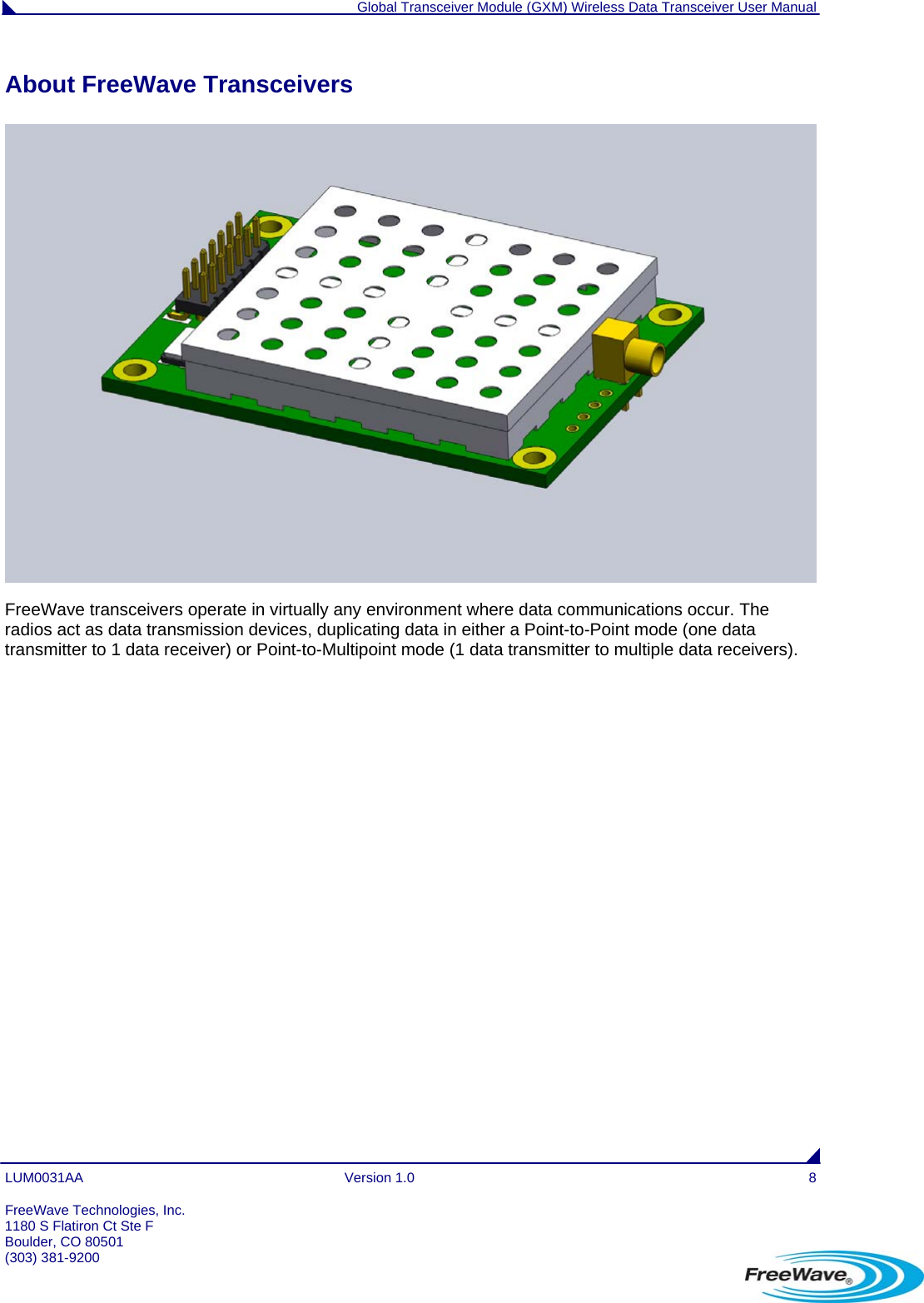
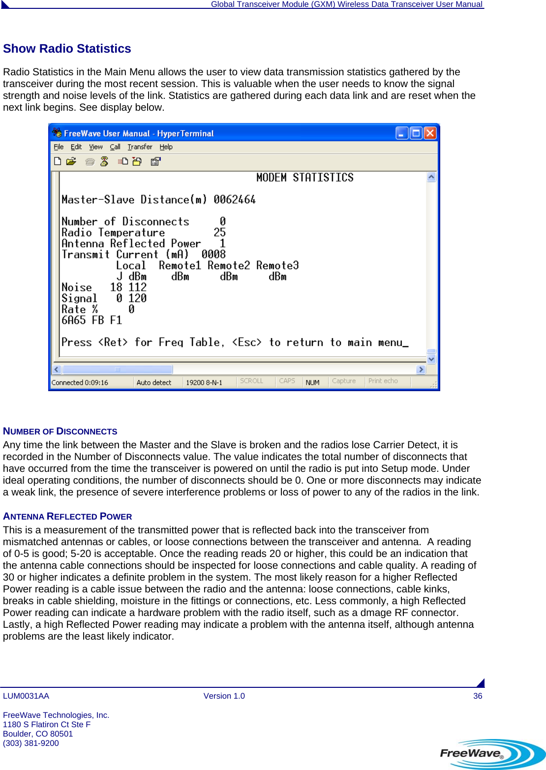
FreeWave Technologies 715712152112 2.4 - 2.4835 GHz Wireless Data Transceiver User Manual manual
FreeWave Technologies Inc. 2.4 - 2.4835 GHz Wireless Data Transceiver manual
UserManual.wiki
>
FreeWave Technologies
>
715712152112 User Manual
manual
Navigation menu
Upload a User Manual
Namespaces
Wiki Guide
HTML
PDF
Info
Views
User Manual
Discussion / Help
Navigation
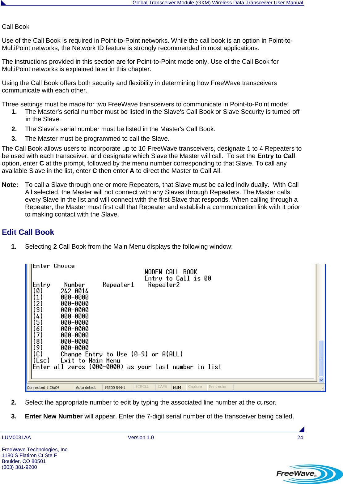
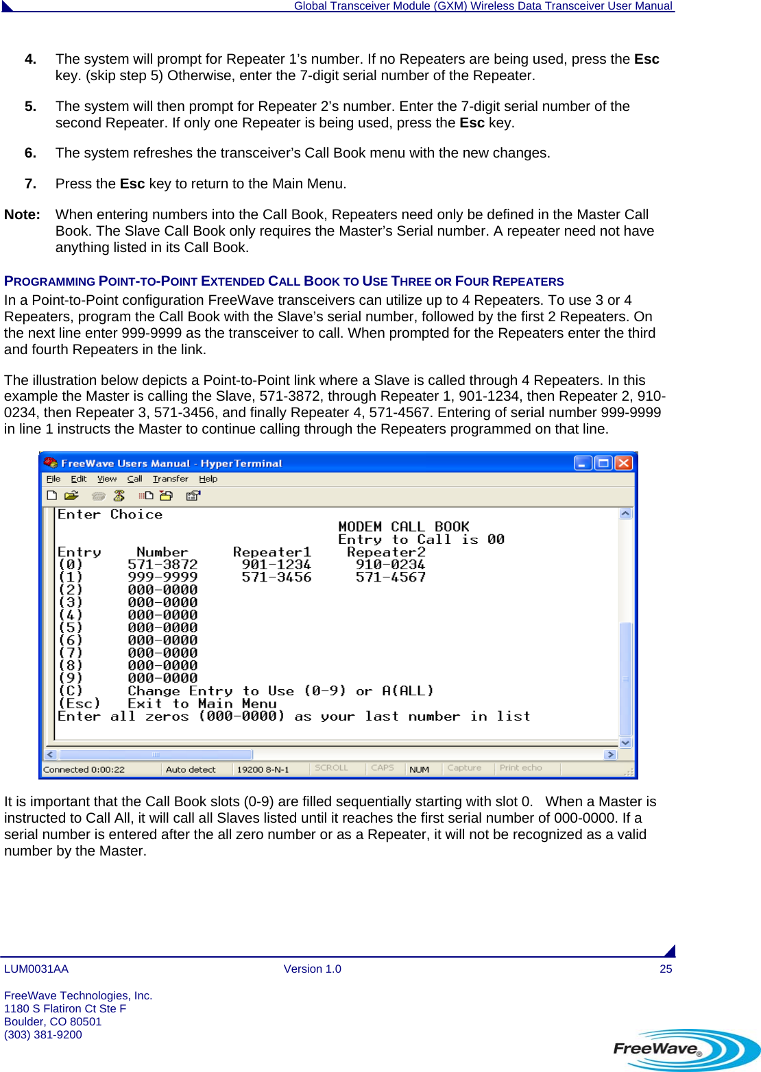
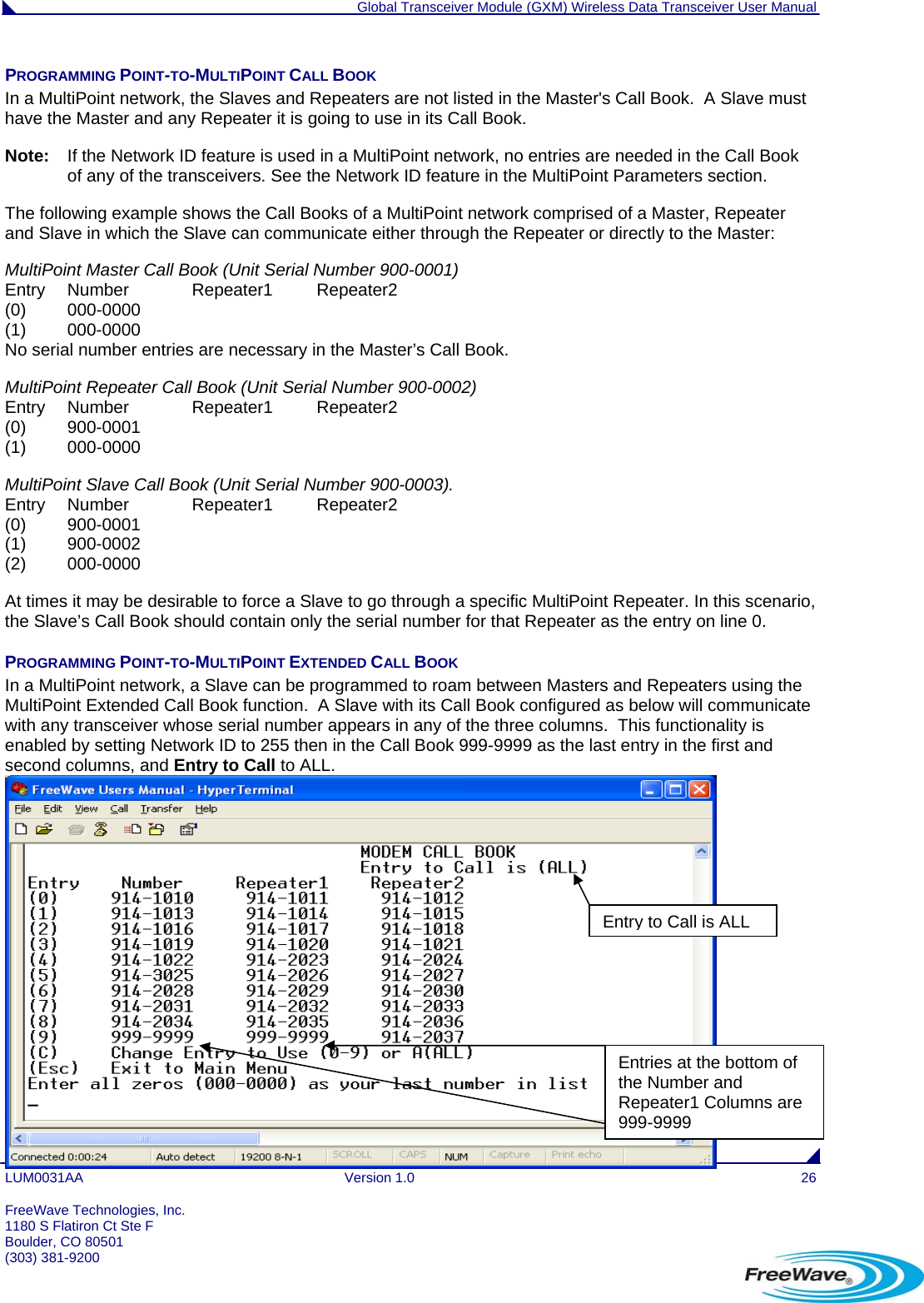
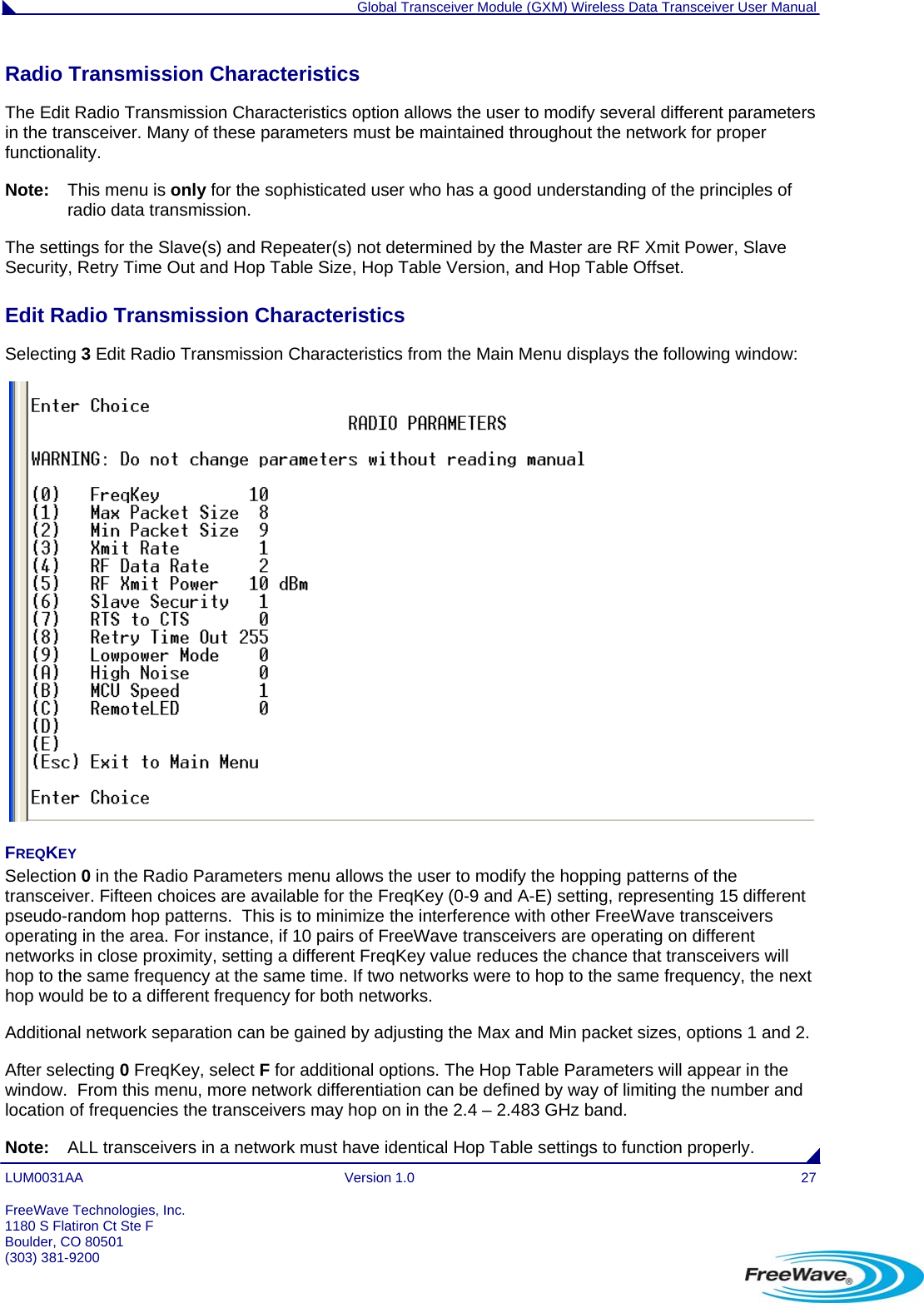
![Global Transceiver Module (GXM) Wireless Data Transceiver User Manual LUM0031AA Version 1.0 53 FreeWave Technologies, Inc. 1180 S Flatiron Ct Ste F GXM Specifications Specification Transmitter Frequency Range 2400 – 2483 MHz ISM Band Output Power 0 dBm (10 mW) to 27 dBm (500 mW) with option to limit to 20 dBm (100 mW) Range – Line-of-sight 20 miles Modulation 2 level GFSK RF Data Rate Selectable speeds, 115.2 or 153.6 Kbps Occupied Bandwidth 230 kHz Hopping Patterns 15 per band, 105 total, user selectable Hopping Channels 3 groups of 80 Hopping Bands 7, user selectable Frequency Zones 16 zones RF Connector MMCX Receiver Sensitivity -105 dBm @ 115.2 Kbps for BER 10-4 -102 dBm @ 153.6 Kbps for BER 10-4 IF Selectivity 20dB at fc +/- 345 kHz Dynamic Range 0 dBm 3rd Order Intercept Point at Input Connector Data Transmission Error Detection 32 Bit CRC, retransmit on error Data Encryption Proprietary Spread Spectrum Technology Data Interface 1200 bps to 230.4 Kbps Data Connector Straight 14-pin or 24-pin dual row header 2.0 mm spacing Data Throughput 115.2 Kbps* Power Requirements Operating Voltage 3.3 to 5.0 VDC Mode 3.3 VDC 5 VDC Transmit 1200 mA 700 mA Receive 165 mA 135 mA Idle 35 mA 19 mA Sleep 8 mA 6 mA Current [mA] Hibernate 0.5 mA 0.5 mA General Information Operating Temperature Range -40° C to +85° C (-40° F to +185° F) Dimensions 50.8 mm L x 36 mm W x 9.6 mm H (2” L x 1.4” W x 0.38” H) Weight 15 g (0.53 oz) Humidity 0% to 95% non-condensing * At 100% receive success rate. RF data rate setting of 2. Boulder, CO 80501 (303) 381-9200](https://usermanual.wiki/FreeWave-Technologies/715712152112/User-Guide-1457600-Page-52.png)