FreeWave Technologies AMI0032AT GXM-T14, GXM-T24 User Manual My
FreeWave Technologies Inc. GXM-T14, GXM-T24 My
UserManual.wiki
>
FreeWave Technologies
>
AMI0032AT User Manual
>
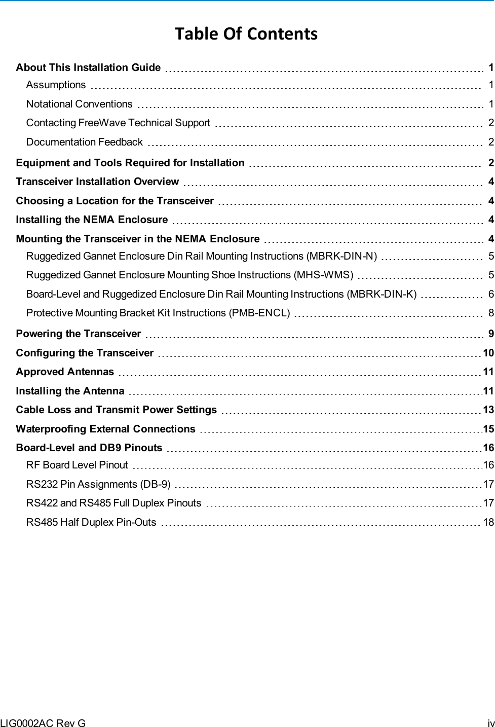
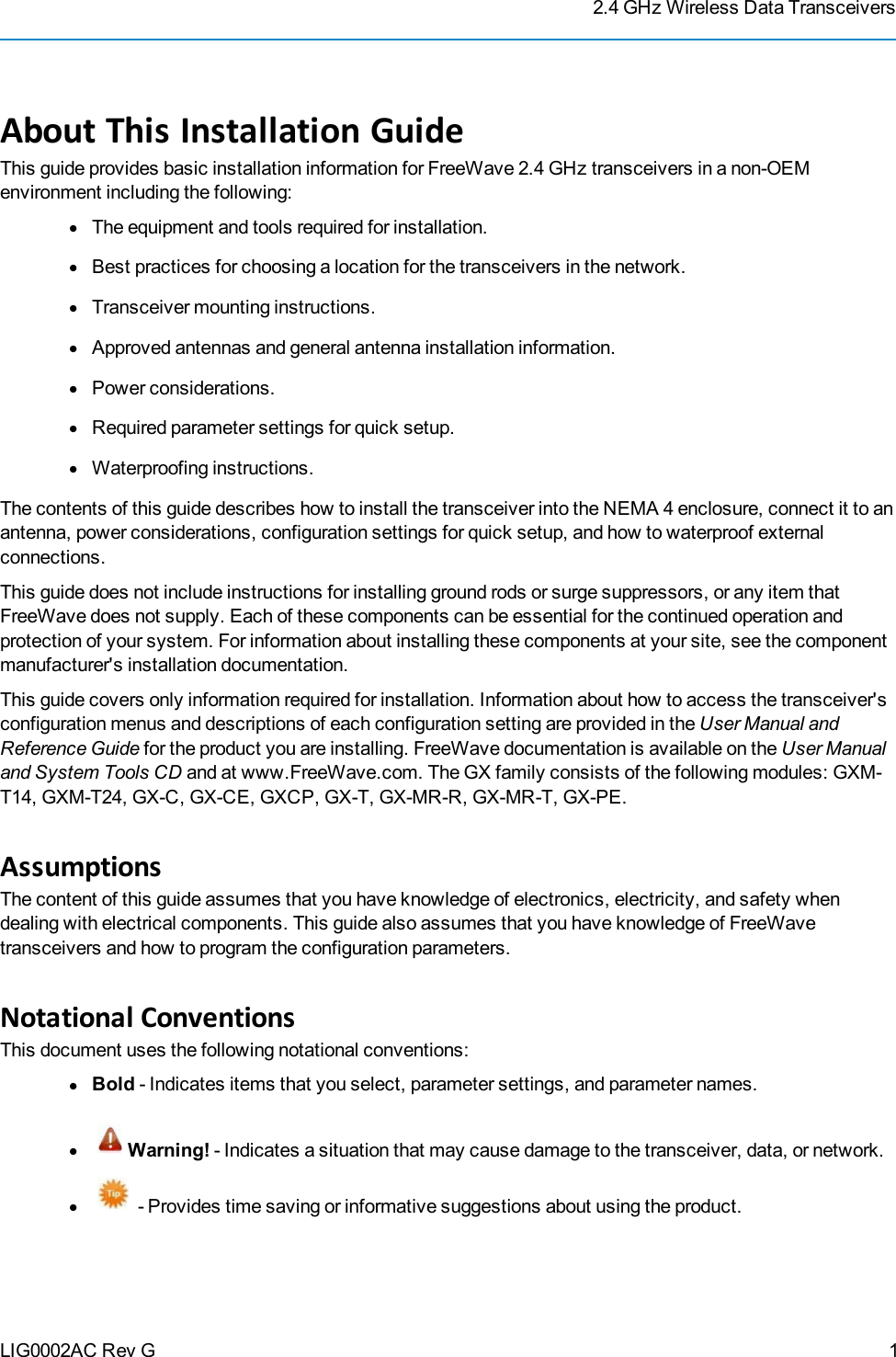
Installation guide
Contents
1.
Installation guide
2.
User Manual
Installation guide
Navigation menu
Upload a User Manual
Namespaces
Wiki Guide
HTML
PDF
Info
Views
User Manual
Discussion / Help
Navigation