FreeWave Technologies AMI0032AT GXM-T14, GXM-T24 User Manual My
FreeWave Technologies Inc. GXM-T14, GXM-T24 My
Contents
- 1. Installation guide
- 2. User Manual
Installation guide

Part Number: LIG0002AC
Revision: G
Last Updated: 12/06/2013
2.4 GHz Wireless Data Transceivers
Installation Guide

Safety Information
Warning! Do not remove or insert diagnostics cable while circuit is live.
Warranty
FreeWave Technologies, Inc. warrants your FreeWave® Wireless Data Transceiver against defects in materials and
manufacturing for a period of two or three years, depending on model from the date of shipment, depending on
model number. In the event of a Product failure due to materials or workmanship, FreeWave will, at its discretion,
repair or replace the Product. For evaluation of Warranty coverage, return the Product to FreeWave upon receiving
a Return Material Authorization(RMA).
In no event will FreeWave Technologies, Inc., its suppliers, or its licensors be liable for any damages arising from
the use of or inability to use this Product. This includes business interruption, loss of business information, or other
loss which may arise from the use of this Product. OEM customer’s warranty periods can vary.
Warranty Policy will not apply in the following circumstances:
1. If Product repair, adjustments, or parts replacements are required due to accident, neglect, or undue
physical, electrical, or electromagnetic stress.
2. If Product is used outside of FreeWave specifications as stated in the Product's data sheet.
3. If Product has been modified, repaired, or altered by Customer unless FreeWave specifically authorized
such alterations in each instance in writing. This includes the addition of conformal coating.
Special Rate Replacement Option
A special rate replacement option is offered to non-warranty returns or upgrades. The option to purchase the
replacement unit at this special rate is only valid for that RMA. The special replacement rate option expires if not
exercised within 30 days of final disposition of RMA.
Restricted Rights
Any product names mentioned in this manual may be trademarks or registered trademarks of their respective
companies and are hereby acknowledged.
This manual is for use by purchasers and other authorized users of FreeWave products.
No part of this manual may be reproduced or transmitted in any form or by any means, electronic or mechanical, or
for any purpose without the express written permission of FreeWave Technologies, Inc. FreeWave reserves the
right to make changes to this manual without notice. FreeWave assumes no responsibility or liability for the use of
this manual or the infringement of any copyright or other proprietary right.
FreeWave products are designed and manufactured in the United States of America.
FreeWave Technologies, Inc.
Boulder, CO
303.381.9200
Toll Free: 1.866.923.6168
Printed in the United States of America. Fax: 303.786.9948
Copyright © 2013 by FreeWave Technologies, Inc. All rights reserved. www.FreeWave.com
LIG0002AC Rev G ii
FreeWave Technologies, Inc. products may be subject to control by the Export Administration Regulations
(EAR) and/or the International Traffic in Arms Regulations (ITAR). Export, re-export, or transfer of these
products without required authorization from the U.S. Department of Commerce, Bureau of Industry and
Security, or the U.S. Department of State, Directorate of Defense Trade Controls, as applicable, is prohibited.
Any party exporting, re-exporting, or transferring FreeWave products is responsible for obtaining all
necessary U.S. government authorizations required to ensure compliance with these and other applicable
U.S. laws. Consult with your legal counsel for further guidance.
UL Notifications
Models GX-C, GX-CE, and GX-T are suitable for use in Class 1, Division 2, Groups A, B, C, and D or non-hazardous
locations only. Do not connect or disconnect any connectors while the circuit is live.
Warning! EXPLOSION HAZARD - SUBSTITUTION OF COMPONENTS MAY IMPAIR
SUITABILITY FOR CLASS 1, DIVISION 2.
Warning! DO NOT REMOVE OR INSERT THE DIAGNOSTICS CABLE WHILE THE
CIRCUIT IS LIVE.
Input voltage for the models listed above is +6.0 to +30.0 VDC.
Important: Input power shall be derived from a single Class 2 power source.
FCC Notifications
This device complies with part 15 of the FCC rules. Operation is subject to the following two conditions: 1) This
device may not cause harmful interference and 2) this device must accept any interference received, including
interference that may cause undesired operation.
The content of this guide covers FreeWave Technologies, Inc. models sold under FCC ID: KNY-1521131FFF (I2
series) and KNYAMI0032AT (GX family).
All models sold under the FCC ID(s) listed above must be installed professionally and are only approved for use
when installed in devices produced by FreeWave Technologies or third party OEMs with the express written
approval of FreeWave Technologies, Inc. Changes or modifications should not be made to the device.
Warning! The I2 series and GX family transceivers have a maximum transmitted output
power of 500 mW. It is recommended that the transmit antenna be kept at least 20 cm away
from nearby persons to satisfy FCC exposure requirements.
The models described in this guide must be installed in a NEMA enclosure. When any FreeWave Technologies,
Inc. module is placed inside an enclosure, a label must be placed on the outside of the enclosure. The label must
include the text "Contains Transmiiter Module with FCC ID: KNY-1521131FFF (I2 series) and KNYAMI0032AT (GX
family)."
LIG0002AC Rev G iii

Table Of Contents
About This InstallationGuide 1
Assumptions 1
Notational Conventions 1
Contacting FreeWave Technical Support 2
Documentation Feedback 2
Equipment and Tools Required for Installation 2
Transceiver Installation Overview 4
Choosing a Location for the Transceiver 4
Installing the NEMA Enclosure 4
Mounting the Transceiver in the NEMA Enclosure 4
Ruggedized Gannet Enclosure Din Rail Mounting Instructions(MBRK-DIN-N) 5
Ruggedized Gannet Enclosure Mounting Shoe Instructions (MHS-WMS) 5
Board-Level and Ruggedized Enclosure Din Rail Mounting Instructions (MBRK-DIN-K) 6
Protective Mounting Bracket Kit Instructions (PMB-ENCL) 8
Powering the Transceiver 9
Configuring the Transceiver 10
Approved Antennas 11
Installing the Antenna 11
Cable Loss and Transmit Power Settings 13
Waterproofing External Connections 15
Board-Level and DB9 Pinouts 16
RF Board Level Pinout 16
RS232 Pin Assignments (DB-9) 17
RS422 and RS485 Full Duplex Pinouts 17
RS485 Half Duplex Pin-Outs 18
LIG0002AC Rev G iv

2.4 GHz Wireless Data Transceivers
LIG0002AC Rev G
About This InstallationGuide
This guide provides basic installation information for FreeWave 2.4 GHz transceivers in a non-OEM
environment including the following:
lThe equipment and tools required for installation.
lBest practices for choosing a location for the transceivers in the network.
lTransceiver mounting instructions.
lApproved antennas and general antenna installation information.
lPower considerations.
lRequired parameter settings for quick setup.
lWaterproofing instructions.
The contents of this guide describes how to install the transceiver into the NEMA 4 enclosure, connect it to an
antenna, power considerations, configuration settings for quick setup, and how to waterproof external
connections.
This guide does not include instructions for installing ground rods or surge suppressors, or any item that
FreeWave does not supply. Each of these components can be essential for the continued operation and
protection of your system. For information about installing these components at your site, see the component
manufacturer's installation documentation.
This guide covers only information required for installation. Information about how to access the transceiver's
configuration menus and descriptions of each configuration setting are provided in the User Manual and
Reference Guide for the product you are installing. FreeWave documentation is available on the User Manual
and System Tools CD and at www.FreeWave.com. The GX family consists of the following modules: GXM-
T14, GXM-T24, GX-C, GX-CE, GXCP, GX-T, GX-MR-R, GX-MR-T, GX-PE.
Assumptions
The content of this guide assumes that you have knowledge of electronics, electricity, and safety when
dealing with electrical components. This guide also assumes that you have knowledge of FreeWave
transceivers and how to program the configuration parameters.
Notational Conventions
This document uses the following notational conventions:
lBold - Indicates items that you select, parameter settings, and parameter names.
lWarning! - Indicates a situation that may cause damage to the transceiver, data, or network.
l- Provides time saving or informative suggestions about using the product.
1

Equipment and Tools Required for Installation
LIG0002AC Rev G
Contacting FreeWave Technical Support
For up-to-date troubleshooting information, check the Support page at www.FreeWave.com.
FreeWave provides technical support Monday through Friday, 7:30 AM to 5:30 PM Mountain Time (GMT -7).
Call toll-free at 1.866.923.6168, within Colorado call 303.381.9200, or contact us through email at
moreinfo@freewave.com.
Documentation Feedback
Send comments or questions about this document's content to techpubs@freewave.com. Include the title of
the document or the document's part number and revision letter (found in the footer) in youremail.
Equipment and Tools Required for Installation
The following equipment and tools are required for installation:
lPermits required for the installation site.
lFreeWave transceiver and its mounting bracket.
lGround rod, wire, and clamp (available at electronic supply stores).
lNational Electrical Manufacturers Association (NEMA) 4 industrial enclosure.
lThe proper antenna for your installation. For information about approved antennas for use with
FreeWave transceivers, see "Approved Antennas" на стр.11.
lOutdoor coaxial cable for antenna installation.
lInterior cables for data and power, available for purchase from FreeWave.
lCable ties.
lCoaxial surge suppressor.
lWaterproofing coax-sealant, foam, or mastic tape.
lElectrical tape.
lElectrical coating (if using foam or mastic tape for waterproofing).
lLaptop with Tool Suite or a terminal emulator installed to program the transceiver. The latest
version of Tool Suite is available on www.FreeWave.com.
lSerial cable or serial-to-USB converter cable.
lDiagnostics cable.
lSpare wire for loop back tests.
lScrewdriver.
lPliers.
lThis installation guide.
2

2.4 GHz Wireless Data Transceivers
LIG0002AC Rev G
lThe user manual associated with the transceiver model you are installing. FreeWave
documentation is available on the User Manual and System Tools CD and at
www.FreeWave.com.
3

Transceiver Installation Overview
LIG0002AC Rev G
Transceiver Installation Overview
To successfully install a transceiver, follow the basic steps listed below.
1. Determine the best location for the transceiver.
2. Install the ground rod.
3. Install the NEMA 4 enclosure
4. Mount the transceiver and power supply into the enclosure.
5. Route data cables to the end device.
6. Connect power and configure the transceiver.
7. Install the antenna.
8. Connect a surge suppressor between the external antenna cable and interior cable connected to
the transceiver's RF connector..
9. Waterproof all external connections.
Choosing a Location for the Transceiver
Placement of the FreeWave transceiver is likely to have a significant impact on its performance. The key to
the overall robustness of the RF link is the height of the antenna. When using an external antenna, placement
of that antenna is critical to a solid data link. Other antennas in close proximity are a potential source of
interference; use the Radio Statistics to help identify potential problems. In general, FreeWave units with a
higher antenna placement will have a better communications link. In practice, the transceiver should be
placed away from computers, telephones, answering machines, and other similar devices. FreeWave
Technologies, Inc. offers directional and Omni directional antennas with cable lengths ranging from 3 to
200feet.
The Show Radio Statistics page is found in option 4 in the main terminal menu or in the Diagnostic information
in Tool Suite. An adjustment as little as 2 feet in antenna placement may resolve some noise issues.
Installing the NEMA Enclosure
The NEMA enclosure selected for the installation site should be a NEMA-4 rated enclosure. NEMA 4
enclosures are gasketed and the door is clamped for maximum sealing. NEMA 4 enclosures are available in
sizes from small wall mounts to two-door floor mount models. The selection depends on the requirements of
the particular installation and the amount of equipment to be placed inside.
Follow the installation instructions provided with the NEMA enclosure, ensuring that no holes are drilled on the
top of the enclosure. Holes on the top of the enclosure can allow moisture and other elements into the
enclosure. Ensure holes on the sides and bottom are waterproofed.
Mounting the Transceiver in the NEMA Enclosure
FreeWave transceivers have several mounting options including metal plates, din rail clips, and brackets.
When mounting any transceiver, ensure that it is mounted to a flat, stable surface using the mounting bracket
or the mounting holes in the corners of board-level transceivers.
4
2.4 GHz Wireless Data Transceivers
LIG0002AC Rev G
Warning! Do not use Velcro to mount the transceiver. Attaching and detaching Velcro
pieces creates an electro-static discharge that may damage the transceiver's circuitry,
or other electronic devices nearby. Mounting a transceiver to a metal surface may
result in an electrical short across the transceiver. Removing Velcro also creates
stress points on board-level transceivers with a great potential to damage the solder
points.
Ruggedized Gannet Enclosure Din Rail Mounting Instructions(MBRK-
DIN-N)
The FreeWave MBRK-DIN-N Din Rail Mounting Bracket Kit is available to mount transceivers in the dark
gray ruggedized Gannet enclosure. The mounting kit ships with the following hardware:
l1 - Din rail mount
l2 - 6-32 x 1/4 inch truss head screws
Depending on the din rail setup, it may be helpful to note the transceiver's serial number and any other
information needed from the transceiver's label. The transceiver snaps out of the mount if you require access
to the label information at a later time.
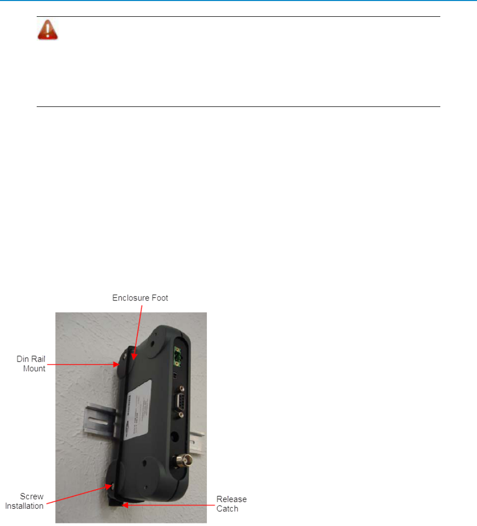
1. Slide the din rail mount over the rear of the
enclosure, ensuring the din rail mount is correctly
oriented so the cut outs for the feet match up with
the feet on the transceiver.
2. Align the holes on the din rail mount with those on
the transceiver. Secure the transceiver to the din
rail mount using the truss head screws provided.
3. Attach the transceiver in its din rail mount to the din
rail.
The din rail mount is designed to allow the
transceiver to be fitted with the LEDs facing to the
left or the right. The only difference is the location of
the release catch either at the top or at the bottom.
To remove the assembly from the din rail mount, insert a small screwdriver into the leverage point on the end
of the release catch and push down lightly approximately 0.25 inches (12.70 mm). The clamp releases and the
assembly can be lifted off.
Ruggedized Gannet Enclosure Mounting Shoe Instructions (MHS-WMS)
The FreeWave MHS-WMS Gannet Enclosure Mounting Shoe is available to mount transceivers in the dark
gray ruggedized Gannet enclosure. The mounting kit ships with the following hardware:
5
Mounting the Transceiver in the NEMA Enclosure
LIG0002AC Rev G
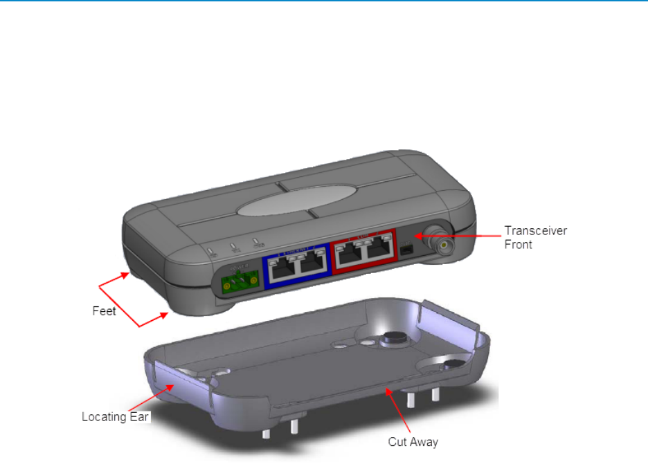
l1 - Mounting shoe
l4 - #8 x 3/4 inch self tapping screws
Depending on your setup, it may be helpful to note the transceiver's serial number and any other information
needed from the transceiver's label. The transceiver snaps out of the mounting shoe if you need to access the
label information at a later time.
The mounting shoe is designed to securely grip the transceiver, allowing it to be mounted either horizontally or
vertically.
1. Secure the mounting shoe to the desired surface following the hole patterns and using the four self-
tapping screws provided.
Ensure the mounting shoe is oriented with the cut-away so that the front of the transceiver is
facing the required direction.
2. Snap the transceiver feet into place in the shoe, ensuring the front of the transceiver aligns with the
cut-away.
To remove the transceiver from the mounting shoe, push one of the locating ears outward and remove the
transceiver from the shoe.
Board-Level and Ruggedized Enclosure Din Rail Mounting Instructions
(MBRK-DIN-K)
The FreeWave MBRK-DIN-K Din Rail Mounting Bracket Kit is available to mount a board-level transceiver or
a transceiver in the light gray ruggedized or waterproof enclosure. The mounting kit ships with the following
hardware:
lRail guide
l8 - 4 lock washers
6
2.4 GHz Wireless Data Transceivers
LIG0002AC Rev G
l8 - 4-40 x 1/4 inch screws
l4 - standoffs
Important: Prior to mounting the bracket to an enclosed transceiver, note the
transceiver's serial number and any other information you might need from the
transceiver's label. After the bracket is attached to the transceiver, the label is no
longer accessible without unscrewing the bracket in its entirety.
After installation, you can retrieve the serial number from the transceiver by reading the
device within ToolSuite or accessing the transceiver's setup menu using a terminal
emulator.
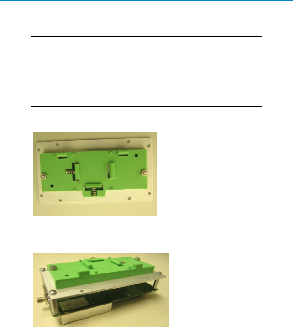
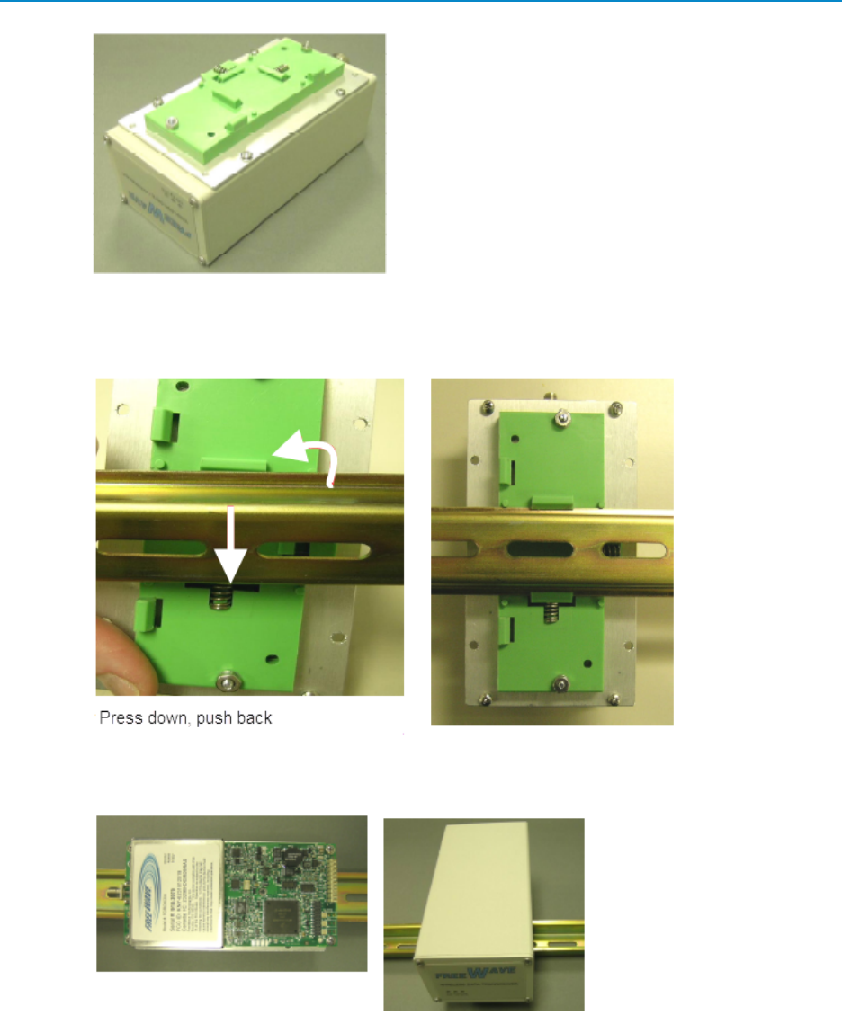
1. Mount with the rail guide slots facing out and the spring loaded guide, into which the rail is inserted,
facing down:
2. For board-level transceivers, place lock washers on all eight of the screws. Attach four of the
standoffs to the flat side of the transceiver with four screws. Align standoffs with the panel holes
and secure with the other four screws.
For enclosed transceivers, place lock washers on four of the screws. Align the bottom enclosure
holes with the panel holes and secure with screws.
7
Mounting the Transceiver in the NEMA Enclosure
LIG0002AC Rev G
3. With the spring guide facing down and with the transceiver's RF connector facing up, attach the
transceiver to the rail by pressing the spring loaded guide onto the rail edge. Push the fixed guide
onto the other side of the rail.
The guides on the contact foot allow the transceiver to be installed vertically or horizontally on the
din rail mount.
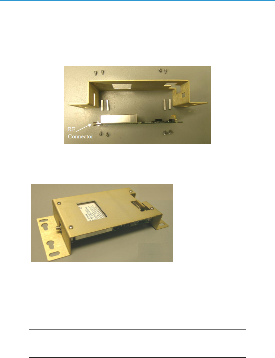
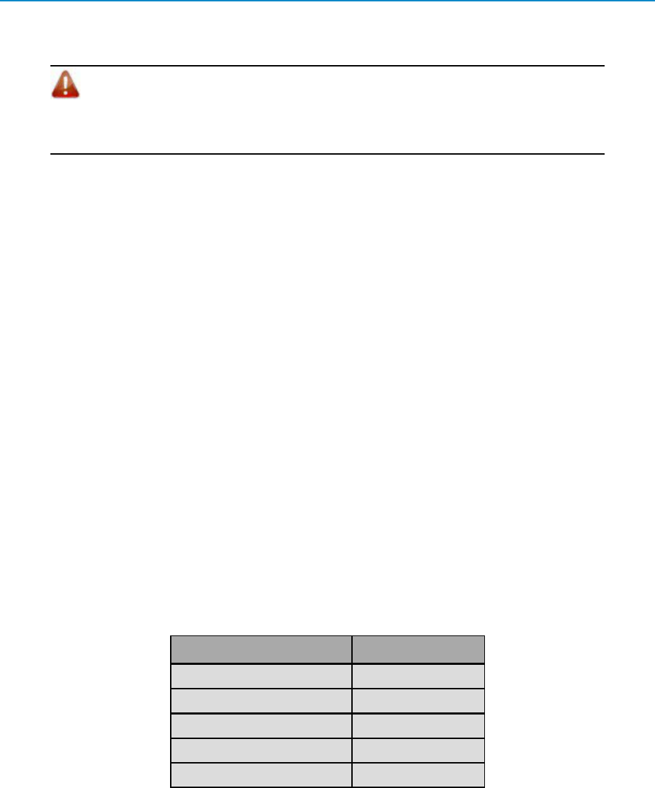
Protective Mounting Bracket Kit Instructions (PMB-ENCL)
The FreeWave PMB-ENCL Protective Mounting Bracket Kit is available to mount a board-level transceiver
other than in a din rail system.The mounting kit ships with the following hardware:
8
2.4 GHz Wireless Data Transceivers
LIG0002AC Rev G
l8 - lock washers
l8 - 4-40 x 1/4 inch screws
l4 - standoffs
Depending on the setup, it may be helpful to note the transceiver's serial number and any other information
needed from the transceiver's label.
1. Place lock washers on all eight of the screws.
2. Attach the standoffs to the front side (non-flat side) of the transceiver with four screws.
3. Align standoffs with the bracket holes and secure with the other four screws.
Powering the Transceiver
To provide power to the transceiver, connect it to a power supply that meets the specifications outlined in the
product's data sheet and the product's user manual.
For any application where the transceiver is used in a UL-controlled environment, the power supply must be a
Class 2 power source. Use a dedicated power supply line.
Important: GX-C, GX-CE, and GX-T transceivers are UL approved for use between
+6.0 to +30.0 VDC. However, for guaranteed performance, FreeWave recommends
using between +7.5 to +30.0 VDC to power the transceiver.
If the power supply line runs outside the enclosure, use electrostatic discharge (ESD) protectors to protect the
transceiver from electric shock, and transient voltage suppressors (TVS) to protect from an over-voltage
9
Configuring the Transceiver
LIG0002AC Rev G
situation. Using both helps enhances reliable operation and can be purchased at most electronic supply
stores.
Warning! If the power supply is above +18.0 VDC, use a 1ohm resistor inline with
power input to the transceiver. For more information, see application note #5467:
Power Wiring Precaution for FGR-Series at High Supply. The cautions outlined in the
application note also apply to the GX family transceivers.
Configuring the Transceiver
A standard network requires that the following parameters are set the same on all transceivers in the network:
lFrequency Key
lHop Table Version
lHop Frequency Offset
lMin Packet Size
lMax Packet Size
lNetwork ID
lRF Data Rate
Transceivers that contain the same settings in all the parameters above can communicate with each other. If
you choose to use the Call Book instead of the Network ID, or the network is a Point-to-Point network, the
Call Book must include the appropriate serial numbers for each transceiver. If the network contains parallel
Repeaters, the Frequency Key setting may differ.
In addition, set the Transmit Power parameter to the appropriate setting based on the cable loss in your
installation. For more information, see "Cable Loss and Transmit Power Settings" на стр.13.
Use a terminal emulator of your choice to access the Setup menu. For any terminal emulator application, plug
the serial cable into a COM port on the transceiver, open a session, and ensure that the port settings are set to
the following for a proper connection to the transceiver:
Port Setting Select
Bits per second 19200
Data Bits 8
Parity None
StopBits 1
Flow Control None
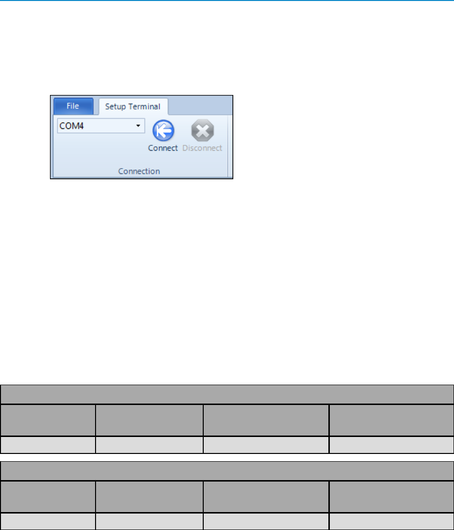
The following instructions describe how to access the transceiver's Setup menu using the Setup Terminal
application within Tool Suite. Setup Terminal contains the port settings above, by default. For more
information about using Tool Suite, see the Tool Suite User Manual available on the User Manual and System
Tools CD or by selecting File > Help in the Tool Suite software.
10
2.4 GHz Wireless Data Transceivers
LIG0002AC Rev G
1. Plug a serial cable into the COM 1 port on the transceiver, connect the cable to a COM port on the
computer running Tool Suite, and connect the transceiver to a power source.
2. OpenToolSuite and select Setup Terminal in the Applications pane.
3. From the drop-down list at the top left of the window, select the COM port on the computer to
which the transceiver is connected.
4. Click Connect.
For information about the settings available, see the User Manual and Reference Guide for the transceiver you
are programming.
Approved Antennas
FreeWave offers omni-directional (Omni) antennas with both bracket and magnetic mounts. Any antenna
used with FreeWave transceivers must have the following characteristics to remain in compliance with FCC
requirements and regulations.
lAntenna gain does not exceed 4 dBI Yagi and 5 dBi Omni
lOverall system Effective IsotropicallyRadiated Power (EIRP) does not exceed 36dBm.
The complete list of antennas available fromFreeWave including antenna gains is shown below:
2.4 GHz Omni-Directional Antennas
Gain dBi Manufacturer
FreeWave Part Number
for Ordering
Manufacturer
Model Number
5.0 dBi Maxrad EAN2405WC MAXC24505
2.4 GHz Whip Stub Omni Antennas
Gain dBi Manufacturer
FreeWave Part Number
for Ordering
Manufacturer
Model Number
1.0 dBi Larsen EAN2400SR SPDA24RP2400
Installing the Antenna
Antennas must be professionally installed on a fixed, mounted, and permanent outdoor structure to satisfy RF
exposure requirements.
11

Installing the Antenna
LIG0002AC Rev G
Warning! Any antenna placed outdoors must be properly grounded. Use extreme
caution when installing antennas and follow all instructions included with the antenna.
Per FCC regulations, any antenna used with FreeWave transceivers must be an approved antenna that has
comparable performance parameters. For more information about approved antennas, see "Approved
Antennas" на стр.11.
When installing an antenna on a pole or tower, ensure the installation complies with the following
requirements:
lIf there are multiple antennas installed on the same pole or tower, ensure there is at least 10 feet
(3.048 meters) vertical separation between antennas on the structure. Installing antennas too
close to one another, even if they are of different frequencies, maycause the energy from one to
interfere with the other.
lIf the antenna is mounted parallel to the pole or tower, ensure there is at least 18 inches (46 cm)
standoff between the structure and the antenna itself. Installing the antenna too close to the
structure to which it is mounted may cause the energy being transmitted from the antenna to
interfere with the antenna itself.
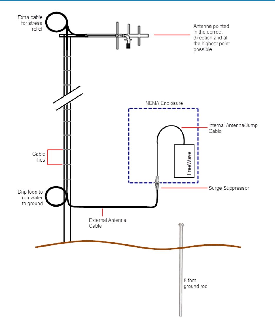
lIf you are installing a directional antenna, set the antenna's direction appropriately. If the antenna
has a moisture weep hole, ensure the antenna is mounted so the weep hole faces down to drain
water.
lRun extra cable at the top of the installation for stress relief (see the illustration below).
lInclude a drip loop of cable at the bottom of the installation that is lower than the NEMA enclosure
(see the illustration below). This loop allows moisture to run off the cable to the ground.
In addition, ensure your installation has the following components and that they are installed according to the
manufacturer's installation instructions:
l8 foot ground rod.
lBulkhead mount surge suppressor.
12
2.4 GHz Wireless Data Transceivers
LIG0002AC Rev G
Cable Loss and Transmit Power Settings
The Transmit Power parameter is the output power of the transceiver. The transceiver output power level
must be set to satisfy maximum Effective IsotropicallyRadiated Power (EIRP) requirements in the country in
which the installation exists.
13
Cable Loss and Transmit Power Settings
LIG0002AC Rev G
When setting up the network, consider the power gain that an antenna may add, and the power loss through
cabling. Adjust the Transmit Power on the transceiver to ensure that you do not exceed the maximum EIRP
for the regulating body where the installation exists. Use the tables below to determine the correct Transmit
Power parameter setting for each transceiver in the network.
Important: The information in this section discusses FCC and ETSI maximum EIRP
regulations. Ensure your installation meets the maximum EIRP requirements for the
country in which you are installing transceivers. It remains the installer's responsibility
to ensure that an installation is within EIRP emission limits.
The FCC permits 27 dBm (0.5 Watt) output power at the transceiver and 36 dBm (4 Watts) at the antenna.
ETSI permits a total of 20 dBm (100 mW) total, which includes the output power at the transceiver and the
antenna gain.When calculating the power gain, use the following equation to determine the total output power
at the antenna.Loss calculations should include cable, connectors, surge protectors, and so on.
Transceiver Output – Losses + Antenna Gain = Output Antenna Power
For example, 30 dBm – 2 dB + 6 dB = 34 dBm (or 2.5 Watts). 34 dBm is within the FCC limits. However,
30dBm – 2dB + 10dB = 38 dBm (or 6.3 Watts) exceeds the FCC limits. Neither is permitted under ETSI
regulations.
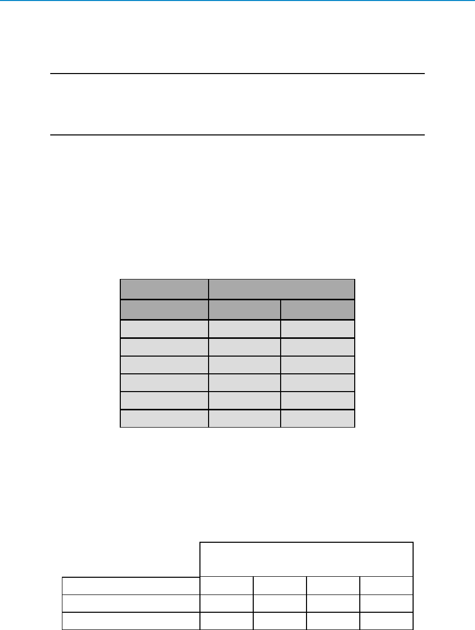
The following table shows the RF loss at various cable lengths:
Cable Type
Length in Feet LMR240 LMR400
10 1.3 dB 0.7 dB
20 2.6 dB 1.4 dB
25 3.2 dB 1.7 dB
30 3.9 dB 2.1 dB
50 6.5 dB 3.4 dB
100 12.9 dB 6.8 dB
In GX family transceivers, the Transmit Power parameter settings range from 0 dBm to 27 dBM (1 mW to
500 mW). The maximum transmit power is capped at 20 dBm at the factory to comply with ETSI regulations
for countries that require it, or capped at other values to comply with country-specific requirements.
The output power can vary slightly between transceivers; however, the output power never exceeds 27dBm
(500 mW).
The following table provides the maximum Transmit Power parameter setting for FreeWave transceivers at a
given antenna gain and cable loss combination. 5 dBi antennas are used in this example.
Cable Loss
Antenna Gain 1 dB 2 dB 3 dB 4 dB
5 dBi Point-to-Point 27 27 27 27
5 dBi Point-to-MultiPoint 27 27 27 27
14
2.4 GHz Wireless Data Transceivers
LIG0002AC Rev G
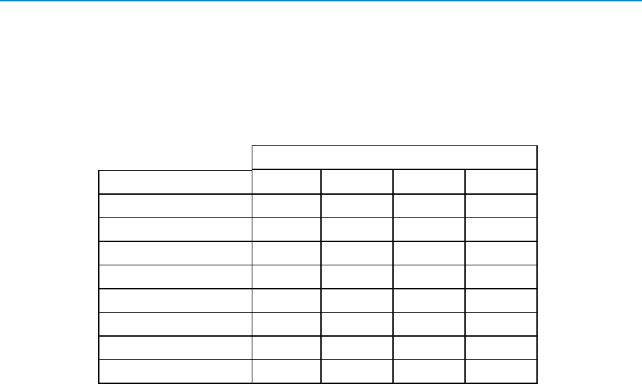
The following table demonstrates how the Transmit Power parameter setting on the transceiver corresponds
to the EIRP indBm with the transceiver-cable-antenna combination for a 4 dBi Yagi antenna at different cable
losses in a Point-to-MultiPoint or Point-to-Point network.
Note: ETSI regulations allow only 20 dBm.
Networks with 4.0 dbi Yagi Antenna
Cable Loss
Transmit Power 1 dB 2 dB 3 dB 4 dB
27 30 29 28 27
26 29 28 27 26
25 28 27 26 25
24 27 26 25 24
23 26 25 24 23
22 25 24 23 22
21 24 23 22 21
20 23 22 21 20
Note: Networks using 2.4 GHz transceivers exclusively for fixed, Point-to-Point
operation may employ transmitting antennas with directional gain greater than
6dBi, provided the maximum peak output power of the intentional radiator is
reduced by 1 dB for every 2 dB that the directional gain of the antenna exceeds
6dBi.
This excludes the use of a Point-to-MultiPoint system, omni-directional
applications, or multiple co-located intentional radiators transmitting the same
information.
Waterproofing External Connections
After you have installed all the components at the site, waterproof all exterior connections with a moldable
plastic coax sealant or using mastic tape and an electrical coating. Ensure that each connection in the
installations is thoroughly sealed.
Moldable coax sealant and other electronic waterproofing supplies are available at most electronic supply
stores. Follow the installation instructions provided with the product to ensure a proper waterproofed seal.
15
Board-Level and DB9 Pinouts
LIG0002AC Rev G
Board-Level and DB9 Pinouts
The information in the following sections provides the pinout connection information for the connectors on the
transceivers.
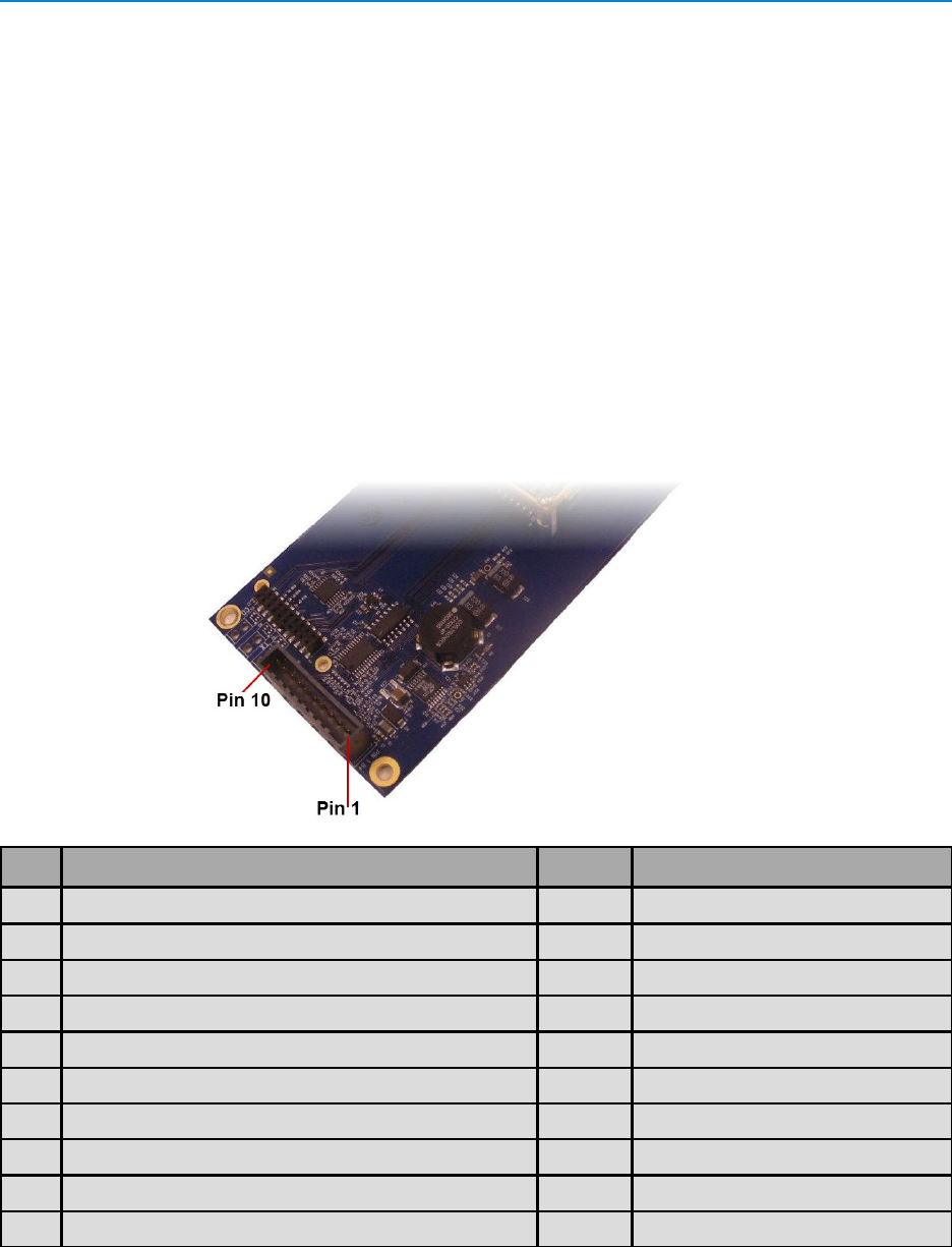
RF Board Level Pinout
The board-level transceivers are available in both TTL and RS232 versions. The TTL version uses reverse
polarity from standard RS232 at 0 to 5 Volt levels. All pin descriptions and pin numbering are the same as the
RS232 version. The RS232 version uses standard RS232 polarity and voltage levels for all of the RS232
signal lines (DTR, Transmit Data, Receive Data, Carrier Detect, RTS, and Clear to Send) and TTL standard
polarity and voltage level for the Interrupt pin.
Pin 1: B+ Power input.
Pin 2: Interrupt (INT) – Input – A 0 Volt level on this pin switches the transceiver into Setup mode.
Pin 1 on the board-level transceiver is the pin farthest from the three LEDs and pin 10 is closest to the LEDs.
Pin Assignment Signal Color on ACS3610xx cable
1 B+ input Power Red
2 Interrupt (temporarily ground to invoke menu) Input Brown
3 Data Terminal Ready (DTR) Input Orange
4 Ground Black
5 Transmit Data (TXD) Output Yellow
6 Ground Black
7 Receive Data (RXD) Input Green
8 Carrier Detect (DCD) Output Blue
9 Request to Send (RTS) Input Violet (purple)
10 Clear to Send (CTS) Output Gray
16

2.4 GHz Wireless Data Transceivers
LIG0002AC Rev G
RS232 Pin Assignments (DB-9)
Pin Assignment Signal Definition
1 CD Carrier
Detect
Output Used to show an RF connection between transceivers.
2 TX Transmit
Data
Output Used to transmit data bits serially from the transceivers to the
system device.
3 RX Receive
Data
Input Used to receive data bits serially from the system device
connected to the transceivers.
4 DTR Data
Terminal
Ready
Input Used only in transceivers in Point-to-Point Slave/Master
switchable mode or for DTR Connect.
5 GND Ground Signal return for all signal lines shared with Pin 9.
6 DSR Data Set
Ready
Output Always high when the transceiver is powered from the 2.5 mm
power connector. Indicates power is on to the transceiver. Also,
this pin can be used for +12.0 Volts when powering the
transceivers directly through the RS232 port.
Note: This is not used on the OEM module.
7 RTS Request to
Send
Input The transceiver does not recognize RTS for flow control. RTS is
used as a control line in RTS/CTS mode.
8 CTS Clear to
Send
Output This signal is used to tell the system device connected to the
transceiver that the transceiver is ready to receive data. When
asserted, the transceiver accepts data, when de-asserted the
transceiver does not accept data. This should always be used for
data rates above 38.4KB or a risk of lost data may occur if an RF
link is not very robust.
9 GND Ground Signal return for all signal lines shared with Pin 5.
RS422 and RS485 Full Duplex Pinouts
Function Bare Board Pin Number DB-9 Pin Number
RX+ 7 3
RX- 9 7
TX+ 5 2
TX- 10 8
Signal Ground 4 or 6 5
17

Board-Level and DB9 Pinouts
LIG0002AC Rev G
RS485 Half Duplex Pin-Outs
Function Bare Board Pin Number DB-9 Pin Number
Wire to both pins for Bus + Short 5 and 7 Short 2 and 3
Wire to both pins for Bus - Short 9 and 10 Short 7 and 8
Signal Ground 4 or 6 5
18