FreeWave Technologies PMT0101AB Module/ZumLink Z9-C or Z9-T User Manual My
FreeWave Technologies Inc. Module/ZumLink Z9-C or Z9-T My
UserManual.wiki
>
FreeWave Technologies
>
PMT0101AB User Manual
Manual
Navigation menu
Upload a User Manual
Namespaces
Wiki Guide
HTML
PDF
Info
Views
User Manual
Discussion / Help
Navigation
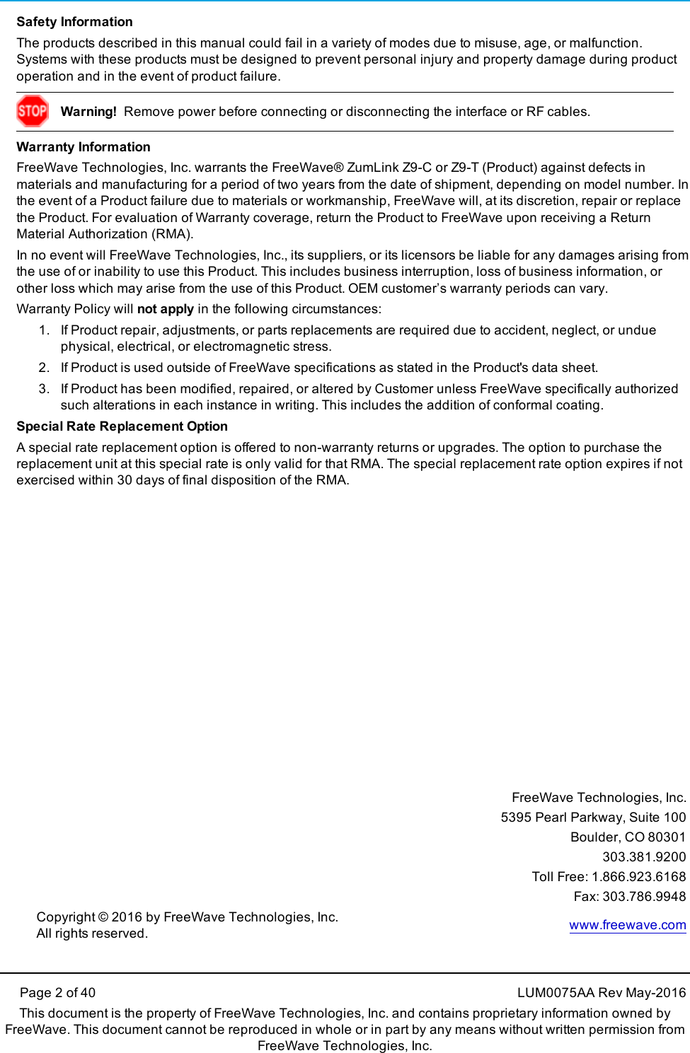
![ZumLink Z9-C or Z9-T: User ManualPrefaceContacting FreeWave Technical SupportFor up-to-date troubleshooting information, check the Support page at www.freewave.com.FreeWave provides technical support Monday through Friday, 8:00 AM to 5:00 PM MountainTime (GMT -7).lCall toll-free at 1.866.923.6168.lIn Colorado, call 303.381.9200.lContact us through e-mail at moreinfo@freewave.com.Printing this DocumentThis document is set to print double-sided with a front cover and a back cover. Viewing thisdocument online with a PDF viewer, may show pages intentionally left blank to accommodate thedouble-sided printing.Document StylesThis document uses these styles:lFreeWave applications appear as: FreeWave.lParameter setting text appears as: [Page=radioSettings]lFile names appear as: configuration.cfg.lFile paths appear as: C:\Program Files (x86)\FreeWave Technologies.lUser-entered text appears as: xxxxxxxxx.l3rd-party names appear as: Notepad®.LUM0075AA Rev May-2016 Page 6 of 40This document is the property of FreeWave Technologies, Inc. and contains proprietary information owned byFreeWave. This document cannot be reproduced in whole or in part by any means without written permission fromFreeWave Technologies, Inc.](https://usermanual.wiki/FreeWave-Technologies/PMT0101AB/User-Guide-3046864-Page-6.png)
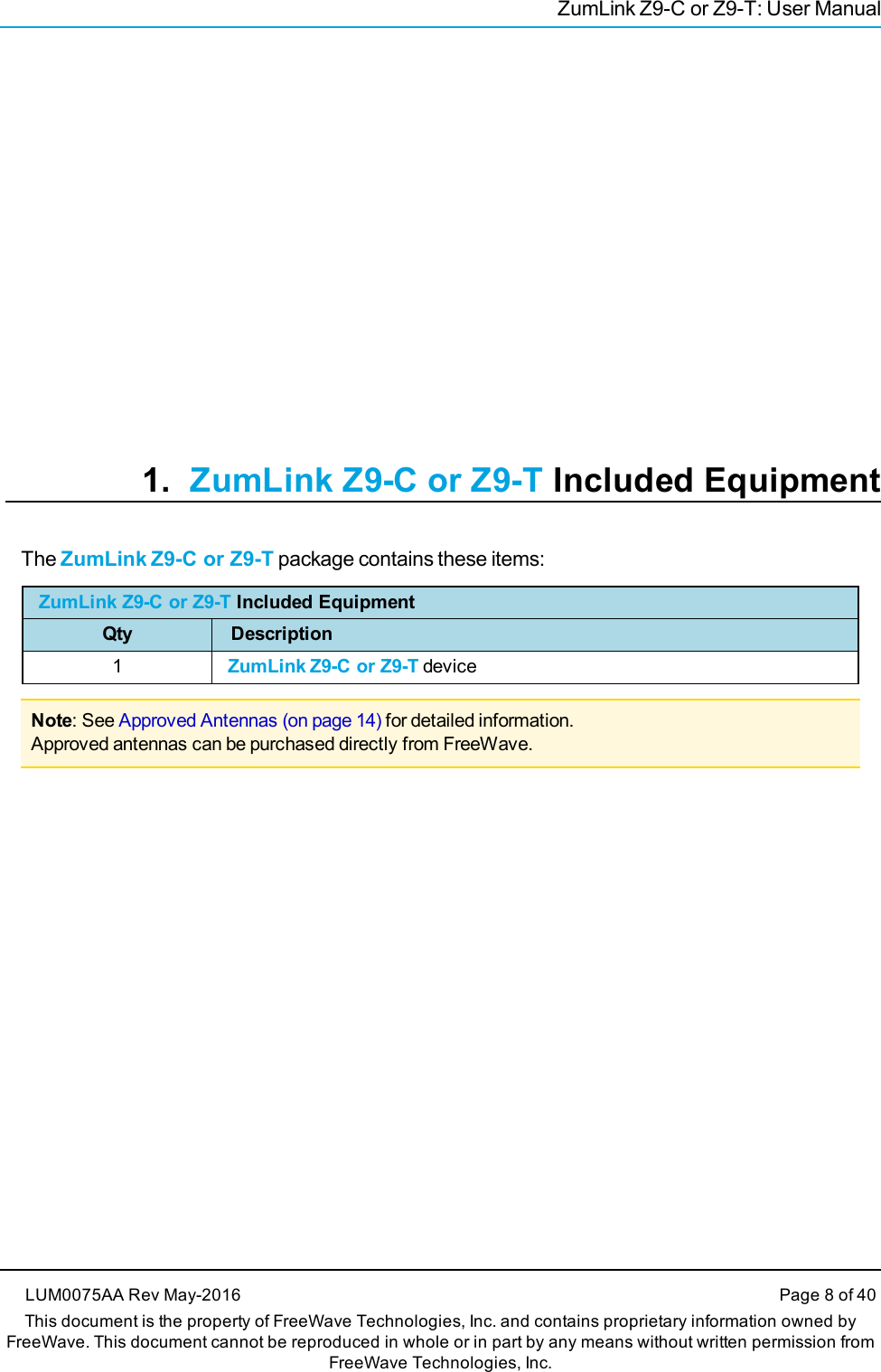
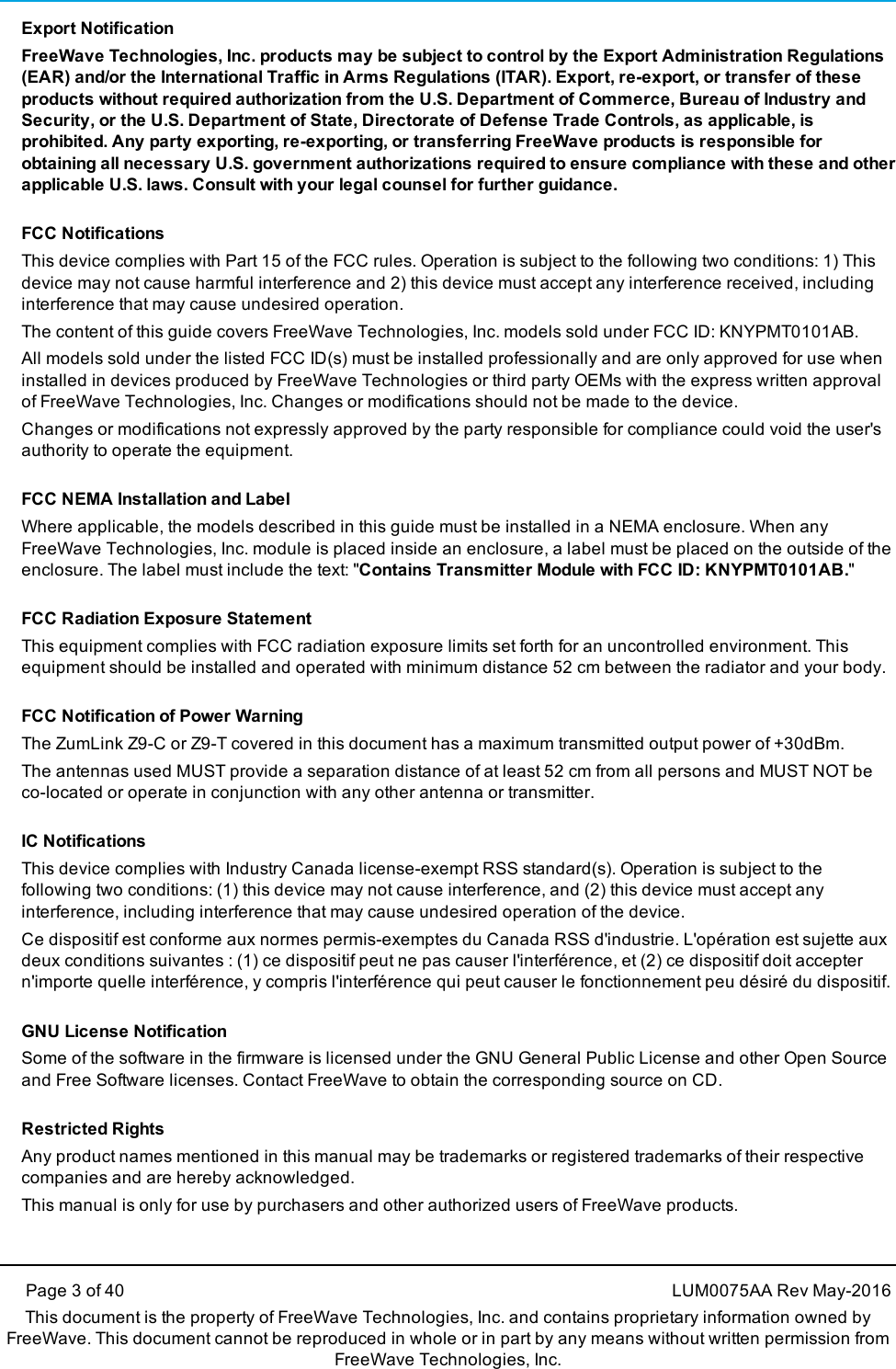
![5. ZumLink Z9-C or Z9-T Settings and DescriptionsPage 19 of 40 LUM0075AA Rev May-2016This document is the property of FreeWave Technologies, Inc. and contains proprietary information owned by FreeWave. This document cannot be reproducedin whole or in part by any means without written permission from FreeWave Technologies, Inc.Note: If the "=" sign is appended to the parameter, it is an implied change to that parameter.If a value is NOT included after the "=", the value becomes a null, space, or 0 (zero) depending on the parameter.Example: Entering txPower returns the current value of txPower.Entering txPower= is an implied change to txPower.If a value is NOTincluded, it changes txPower to 10.configconfig - ZumLink Settings and DescriptionsPage CLI Command Description[Page=config] config.factoryDefaults= This setting restores the ZumLink to its factory default configuration.Example:config.factoryDefaults=set[Page=config] config.reset= All options reset the ZumLink Z9-C or Z9-T.The options are:lconfig.reset=nowlconfig.reset=reboot is this valid? John to verifylconfig.reset=reset is this valid? John to verify[Page=config] config.restore= This setting reloads the config settings of the ZumLink that were saved.Phil asks: What are the options?Note: Restore happens automatically when the ZumLink starts.[Page=config] config.save= This setting saves changes made to the ZumLink configuration.Phil asks: Is NOW the only option? I think one option is config.save=1.Example:config.save=now](https://usermanual.wiki/FreeWave-Technologies/PMT0101AB/User-Guide-3046864-Page-19.png)
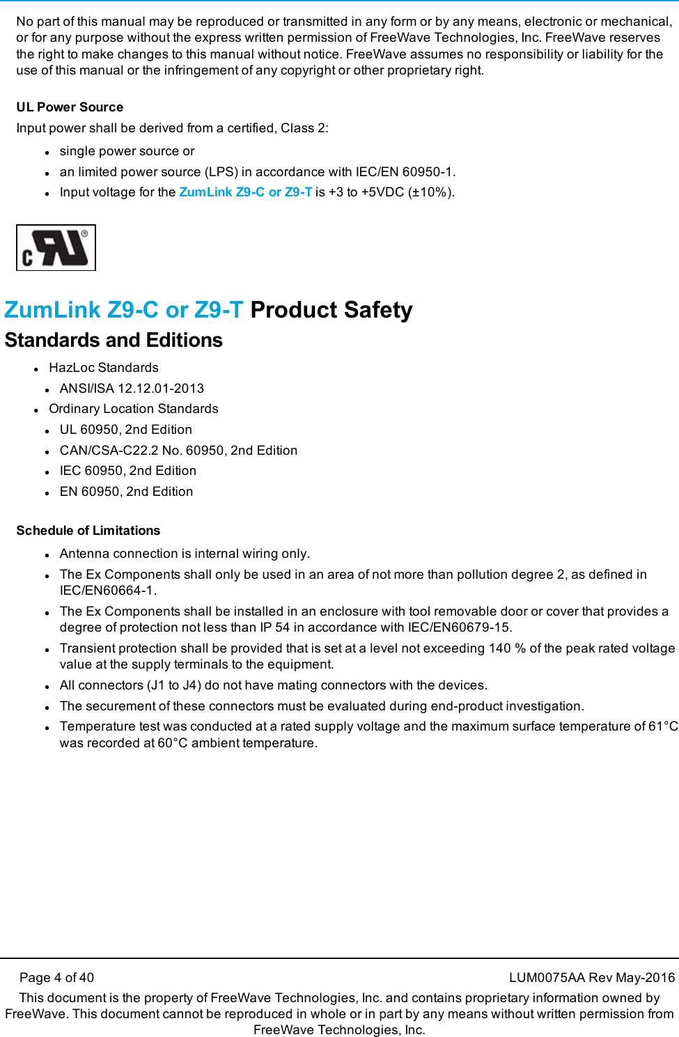
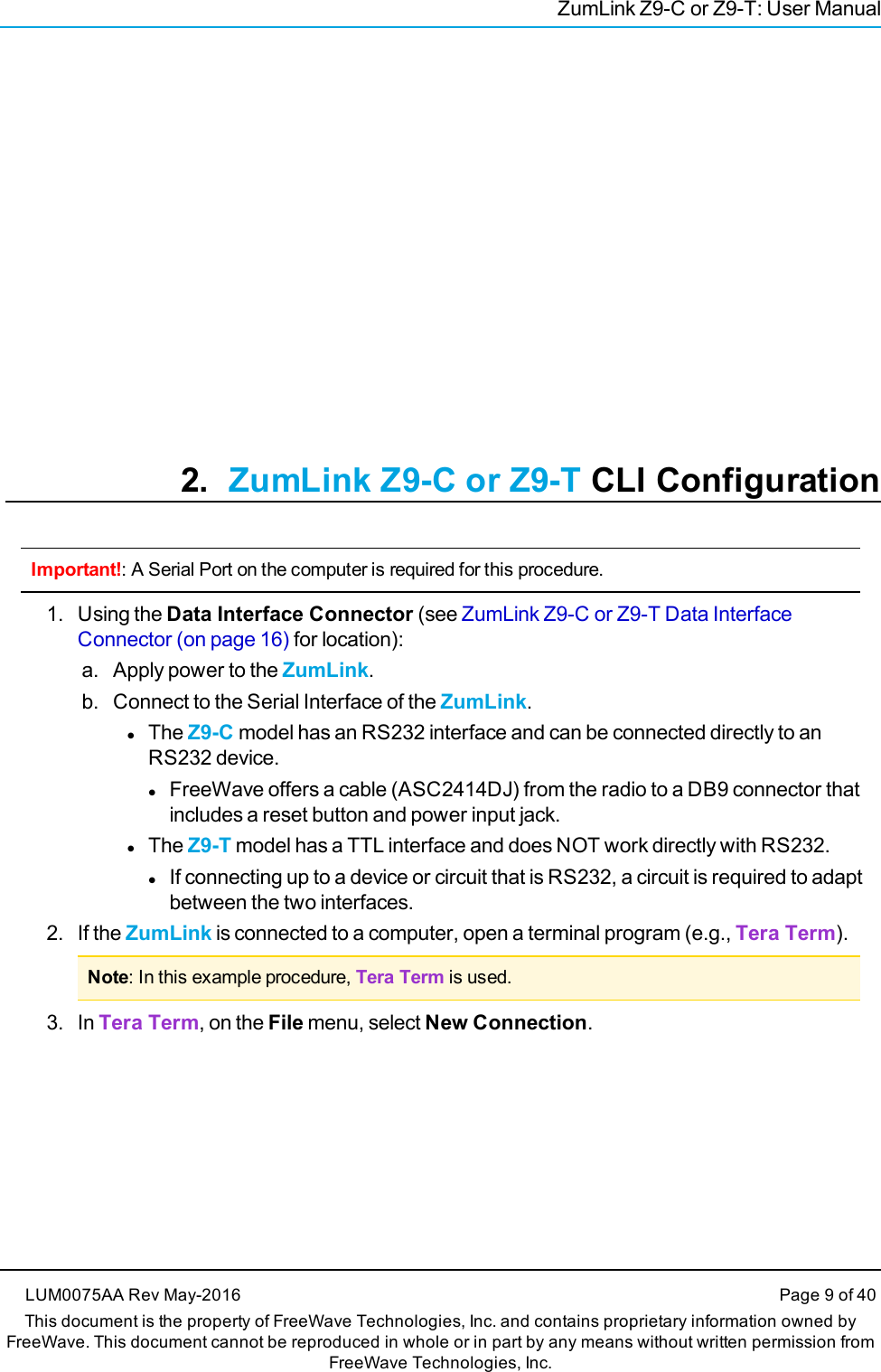
![ZumLink Z9-C or Z9-TdiagPortConfigdiagPortConfig - ZumLink Settings and DescriptionsPage CLI Command Description[Page=diagPortConfig] diagPortConfig.cliBaudRate= This setting sets the baud rate for the diagnostic port.The options are:lWhat are the options here?lllNote: The default value is 115200.[Page=diagPortConfig] diagPortConfig.databits= This setting defines the byte length for the diagnostic port.The options are:l7 bitsl8 bitsNote: The default value is 8.[Page=diagPortConfig] diagPortConfig.diagBaudRate=Note: The default value is 115200.LUM0075AA Rev May-2016 Page 20 of 40This document is the property of FreeWave Technologies, Inc. and contains proprietary information owned by FreeWave. This document cannot be reproducedin whole or in part by any means without written permission from FreeWave Technologies, Inc.](https://usermanual.wiki/FreeWave-Technologies/PMT0101AB/User-Guide-3046864-Page-20.png)
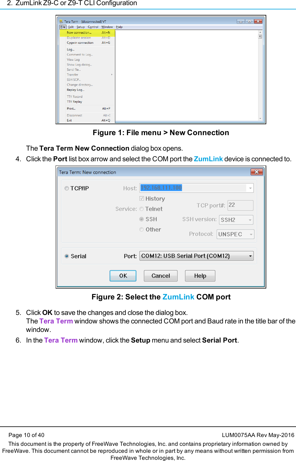
![5. ZumLink Z9-C or Z9-T Settings and DescriptionsPage 21 of 40 LUM0075AA Rev May-2016This document is the property of FreeWave Technologies, Inc. and contains proprietary information owned by FreeWave. This document cannot be reproducedin whole or in part by any means without written permission from FreeWave Technologies, Inc.diagPortConfig - ZumLink Settings and DescriptionsPage CLI Command Description[Page=diagPortConfig] diagPortConfig.diagMode=The options are:lPacketizedlWhat other options are there?llNote: The default value is Diag.[Page=diagPortConfig] diagPortConfig.parity= This setting defines the parity for the diagnostic port.The options are:lOddlEvenlNoneNote: The default value is None.[Page=diagPortConfig] diagPortConfig.stopbits= This setting defines the number of stop bits for the diagnostic port.The options are:lNonel1l2Note: The default value is 1.](https://usermanual.wiki/FreeWave-Technologies/PMT0101AB/User-Guide-3046864-Page-21.png)
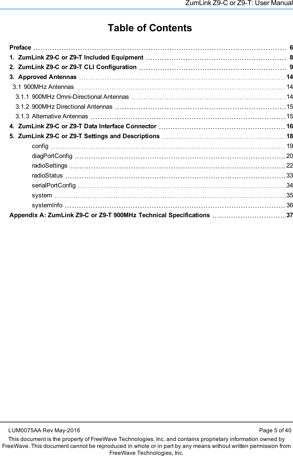
![ZumLink Z9-C or Z9-TradioSettingsradioSettings - ZumLink Settings and DescriptionsPage CLI Command Description[Page=radioSettings] radioSettings.beaconInterval= Note: This setting is only available when Frequency Hopping isenabled.The beaconInterval controls how often a Gateway radio sends out abeacon packet and changes to the next radio frequency in the hoppingpattern.lA longer beaconInterval gives the system better throughput inchannel environments where interference is minimal.lThroughput can be improved in some situations with shorter beaconintervals.Important!: The Endpoint radios will obtain this value from aGateway with the same networkId.Editing this value when the radioMode is set to Endpoint willreturn an OK; HOWEVER, the value will become what theGateway is set to as soon as it processes a received beacon.The options are:lTWENTY_FIVE_MSlFIFTY_MSlONE_HUNDRED_MSlTWO_HUNDRED_MSlFOUR_HUNDRED_MSExample:radioSettings.beaconInterval=FIFTY_MS.Note: The default value is FOUR_HUNDRED_MS.LUM0075AA Rev May-2016 Page 22 of 40This document is the property of FreeWave Technologies, Inc. and contains proprietary information owned by FreeWave. This document cannot be reproducedin whole or in part by any means without written permission from FreeWave Technologies, Inc.](https://usermanual.wiki/FreeWave-Technologies/PMT0101AB/User-Guide-3046864-Page-22.png)
![5. ZumLink Z9-C or Z9-T Settings and DescriptionsPage 23 of 40 LUM0075AA Rev May-2016This document is the property of FreeWave Technologies, Inc. and contains proprietary information owned by FreeWave. This document cannot be reproducedin whole or in part by any means without written permission from FreeWave Technologies, Inc.radioSettings - ZumLink Settings and DescriptionsPage CLI Command Description[Page=radioSettings] radioSettings.ccaRssiThresh=- This parameter uses the receive signal strength to determine if there isa signal on the radio before transmission.Note: The default value is -82.[Page=radioSettings] radioSettings.frequencyKey= Note: This setting is only available when Frequency Hopping isenabled.The Frequency Key is a number used as an index to select a hoppingtable.Note: The Endpoint radios will obtain this value from a Gatewaywith the same networkId.lThe Frequency Key setting boundaries are 0 (zero) to 31.lWhen a hop table loads, the Frequency Key is adjusted towhatever is available in the actual hop table.lAn invalid frequency setting is determined by being outside of thespecified range.lIf an invalid frequency setting is found, the Frequency Key isNOT changed.lA frequency setting can also be invalid if the Frequency Key settingis larger than the number of hopping tables for a specific rfDataRate.lIn that case, the Frequency Key is set to 0 (zero).lThe options are Key0 (zero) to Key23.Note: The default value is Key0 (zero).](https://usermanual.wiki/FreeWave-Technologies/PMT0101AB/User-Guide-3046864-Page-23.png)
![ZumLink Z9-C or Z9-TradioSettings - ZumLink Settings and DescriptionsPage CLI Command Description[Page=radioSettings] radioSettings.frequencyMasks= Frequency Masks are used to mask off frequencies or a set offrequencies in a hop table.Single Channel FormatlfrequencyMasks=xxx.yyyy,xxx.yyyy,xxx.yyyy.Example: frequencyMasks=903.0000,908.0000,925.0000.Range of Channels FormatlfrequencyMasks=xxx.yyyy-xxx.yyyy,xxx.yyyy.Example: frequencyMasks=902.1000-905.1000,920.1000-927.9000Combination of Channels FormatlfrequencyMasks=902.1000-905.1000,920.1000-927.9000,915.0200Where:lxxx is a value between 902-927.lyyyy is a value between .0000-.9999.Note: Least significant digits are not required.Example: .9, .09, .009 are valid entries.Important!: Frequency mask entries MUST BE less than 128bytes.A comma MUST separate the values - NOT a comma and aspace.LUM0075AA Rev May-2016 Page 24 of 40This document is the property of FreeWave Technologies, Inc. and contains proprietary information owned by FreeWave. This document cannot be reproducedin whole or in part by any means without written permission from FreeWave Technologies, Inc.](https://usermanual.wiki/FreeWave-Technologies/PMT0101AB/User-Guide-3046864-Page-24.png)
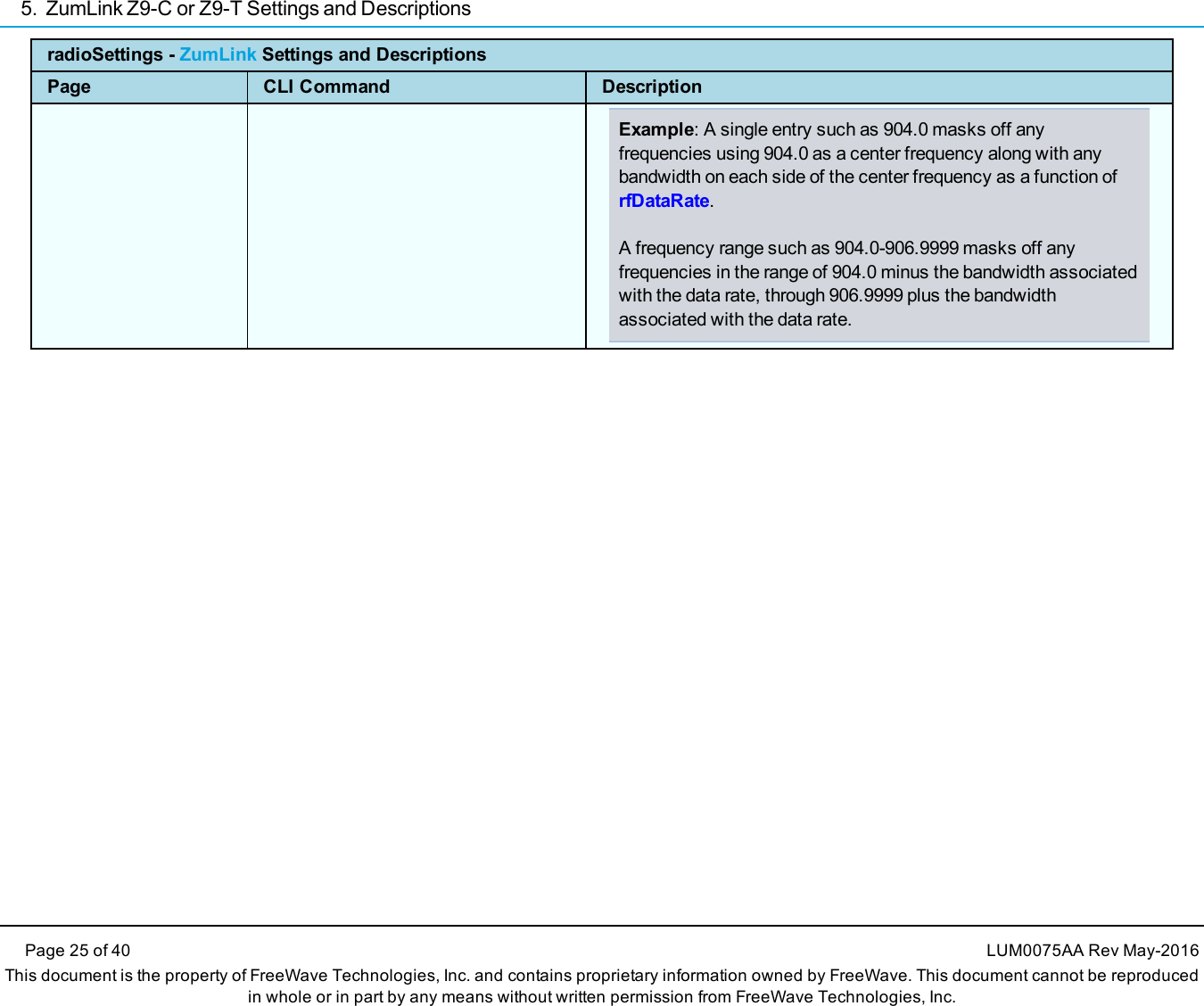
![ZumLink Z9-C or Z9-TradioSettings - ZumLink Settings and DescriptionsPage CLI Command Description[Page=radioSettings] radioSettings.frequencyMasks=(continued)lErrors occur when masking reduces the number of frequenciesbelow regulatory minimums.lFor channel sizes < 500kHz, the radio must frequency hop.lThis does NOT apply for channel sizes greater than 500 kHzwhich can operate single channel or frequency hopping.lIf the radioSettings.rfDataRate=RATE_250K:lIf the number of hopping channels is >= 50, the maximumtxPower is 30dBm.lIf the number of channels is 25 to 49, the maximum txPower is24dBm.lIf the number of hopping channels contained in the hop table is <25, all masking is removed and all of the channels contained inthe hop table are re-enabled and txPower is NOT changed.lIf the radioSettings.rfDataRate=RATE_115.2K:lIf the number of hopping channels is >= 50, the maximumtxPower is 30dBm.lIf the number of hopping channels contained in the hop table is <50, all masking is removed and all of the channels contained inthe hop table are re-enabled and txPower is NOT changed.NoteslBoth Gateway and Endpoint radios MUST use the same value forthe frequencyMasks setting.lIf the frequencyMasks comes back empty seefrequencyMasksErrors for any errors.lUse frequencyMasks=1 to clear the frequency Masks.John asks if there's another way to do this clearing?Note: The default value is Blank.LUM0075AA Rev May-2016 Page 26 of 40This document is the property of FreeWave Technologies, Inc. and contains proprietary information owned by FreeWave. This document cannot be reproducedin whole or in part by any means without written permission from FreeWave Technologies, Inc.](https://usermanual.wiki/FreeWave-Technologies/PMT0101AB/User-Guide-3046864-Page-26.png)
![5. ZumLink Z9-C or Z9-T Settings and DescriptionsPage 27 of 40 LUM0075AA Rev May-2016This document is the property of FreeWave Technologies, Inc. and contains proprietary information owned by FreeWave. This document cannot be reproducedin whole or in part by any means without written permission from FreeWave Technologies, Inc.radioSettings - ZumLink Settings and DescriptionsPage CLI Command Description[Page=radioSettings] radioSettings.lnaBypass= The lnaBypass setting controls enabling and disabling the Low NoiseAmplifier (LNA) which can boost the receive signal by 10dB.lThe options are 0 (zero) and 1.lWhen the lnaBypass=1, the LNA of the radio module isbypassed.lIf lnaBypass=0, the LNA is enabled.lIf lnaBypass=<anything but 0> it is set to 1.It can be useful to bypass the LNA if there is a presence ofstrong signals in band and packet reception is not good.Note: The default value is 0 (zero).[Page=radioSettings] radioSettings.maxLinkDistanceinMiles= The maxLinkDistanceinMiles setting controls the maximum one-waydistance (in miles) between any node in the network.Important!: All nodes in the network that communicate with eachother should use the same distance value.lThe minimum value is 0 (zero) miles.lThe maximum value is 120 miles.Note: The default value is 20 miles.](https://usermanual.wiki/FreeWave-Technologies/PMT0101AB/User-Guide-3046864-Page-27.png)
![ZumLink Z9-C or Z9-TradioSettings - ZumLink Settings and DescriptionsPage CLI Command Description[Page=radioSettings] radioSettings.maxPacketSize= John asks: Can this really be set from the CLIJohn says this CANNOT be changed in Thor Ais this other content applicable to Thor B?Note: This is a ZumLink Golden Setting.lThe options are any number between 0 and 9.lMax packet size can be optimized.FreeWave Recommends: Use the default settings for normaloperation.[Page=radioSettings] radioSettings.networkId= Note: This is a ZumLink Golden Setting.This is the Network Identifier. The networkId setting is used tosubdivide traffic on radio units.lRadio units can only communicate with other units that have thesame networkId setting.Note: If radios are on the same frequency they will still receivedata from radios of a different networkId, but the data is dropped.Enter any number between 0 and 65535.Note: The default value is 43981.LUM0075AA Rev May-2016 Page 28 of 40This document is the property of FreeWave Technologies, Inc. and contains proprietary information owned by FreeWave. This document cannot be reproducedin whole or in part by any means without written permission from FreeWave Technologies, Inc.](https://usermanual.wiki/FreeWave-Technologies/PMT0101AB/User-Guide-3046864-Page-28.png)
![5. ZumLink Z9-C or Z9-T Settings and DescriptionsPage 29 of 40 LUM0075AA Rev May-2016This document is the property of FreeWave Technologies, Inc. and contains proprietary information owned by FreeWave. This document cannot be reproducedin whole or in part by any means without written permission from FreeWave Technologies, Inc.radioSettings - ZumLink Settings and DescriptionsPage CLI Command Description[Page=radioSettings] radioSettings.nodeId= Important!: Each radio with the same networkId must have aUNIQUE nodeId.lThis setting defines the ID of the radio.lThe Gateway device will always have a nodeId of value 1.lEnter any number between 2 and 65533.Note: The default value is a unique number between 2 and 65533for an Endpoint.](https://usermanual.wiki/FreeWave-Technologies/PMT0101AB/User-Guide-3046864-Page-29.png)
![ZumLink Z9-C or Z9-TradioSettings - ZumLink Settings and DescriptionsPage CLI Command Description[Page=radioSettings] radioSettings.radioFrequency= Note: This is a ZumLink Golden Setting.This setting designates the Operating Center Frequency in MHz.lThe radioFrequency parameter ONLY takes effect whenradioHoppingMode=Hopping_Off.lAll radios in a network must have the same frequency.lIf the radioFrequency parameter is set too close to the band edgefor the current rfDataRate, the radio module will reject the setting.Read back this value after setting it to determine if it wasaccepted by the radio module.Valid boundaries are:l4M data rate: 904.5504 - 925.7472 MHzl1M data rate: 903.0528 - 927.0144 MHzl500K data rate: 902.7072 - 927.3600 MHzl250K data rate: 902.5344 - 927.4176 MHzl115.2K data rate: 902.4768 - 927.5904 MHzNote: The default value is 915.0000.LUM0075AA Rev May-2016 Page 30 of 40This document is the property of FreeWave Technologies, Inc. and contains proprietary information owned by FreeWave. This document cannot be reproducedin whole or in part by any means without written permission from FreeWave Technologies, Inc.](https://usermanual.wiki/FreeWave-Technologies/PMT0101AB/User-Guide-3046864-Page-30.png)
![5. ZumLink Z9-C or Z9-T Settings and DescriptionsPage 31 of 40 LUM0075AA Rev May-2016This document is the property of FreeWave Technologies, Inc. and contains proprietary information owned by FreeWave. This document cannot be reproducedin whole or in part by any means without written permission from FreeWave Technologies, Inc.radioSettings - ZumLink Settings and DescriptionsPage CLI Command Description[Page=radioSettings] radioSettings.radioHoppingMode= Note: This is a ZumLink Golden Setting.The radioHoppingMode parameter is used to enable or disablefrequency hopping.Important!: The Gateway and Endpoint radios MUST use thesame value for this setting.lFor rfDataRate values >= 500kbps, the choice of hopping modeshould be selected based on network frequency planning andchannel conditions.lFor rfDataRate values < 500kbs, radioHoppingMode is forced On.The options are:lHopping_OfflHopping_OnExample:radioSettings.radioHoppingMode=Hopping_On.Note: The default value is Hopping_Off.[Page=radioSettings] radioSettings.radioMode= This setting designates the device as a Gateway or Endpoint unit.lEach network MUST have only ONE Gateway unit.lThe remaining units MUST be configured as Endpoints.lThe Gateway device will always have a nodeId of value 1.lA Gateway is only needed when Frequency Hopping is enabled.lA Gateway is NOT required when operating with a single channel.Note: The default value is Endpoint.](https://usermanual.wiki/FreeWave-Technologies/PMT0101AB/User-Guide-3046864-Page-31.png)
![ZumLink Z9-C or Z9-TradioSettings - ZumLink Settings and DescriptionsPage CLI Command Description[Page=radioSettings] radioSettings.rfDataRate= Note: This is a ZumLink Golden Setting.This setting defines the RF link data rate speed in bits per second.lA higher RF link data rate provides more throughput at the expenseof link distance or fade margin.lWhen changing from lower data rates to higher ones (e.g., RATE_115.2K to RATE_1M), the radioFrequency may be set back to915.000 MHz if the signal would have been out of band.lThe communication range is dependent on the rfDataRate setting.lThe min value increases and the max value decreases as therfDataRate increases.lThe increase of channel bandwidth affects these ranges.Important!: The Gateway and Endpoint radios MUST use thesame value for this setting.The options are:lRATE_4MlRATE_1MlRATE_500KlRATE_250KlRATE_115.2KNote: The default value is RATE_1M.LUM0075AA Rev May-2016 Page 32 of 40This document is the property of FreeWave Technologies, Inc. and contains proprietary information owned by FreeWave. This document cannot be reproducedin whole or in part by any means without written permission from FreeWave Technologies, Inc.](https://usermanual.wiki/FreeWave-Technologies/PMT0101AB/User-Guide-3046864-Page-32.png)
![5. ZumLink Z9-C or Z9-T Settings and DescriptionsPage 33 of 40 LUM0075AA Rev May-2016This document is the property of FreeWave Technologies, Inc. and contains proprietary information owned by FreeWave. This document cannot be reproducedin whole or in part by any means without written permission from FreeWave Technologies, Inc.radioSettings - ZumLink Settings and DescriptionsPage CLI Command Description[Page=radioSettings] radioSettings.txPower= lThis setting defines the RF output transmit power for the radio.lA higher power can be used to increase link margin.lUse a lower transmit power to reduce interference when multipleradio networks are in close proximity.lEnter 10 to 30lAt 250K rfDataRate, if the number of frequencies in the hop table is>= to 50 after the masks are applied, txPower is limited to 30dB.lIf the number of frequencies are >= 30, but < 50, txPower is set to.25 W (24dbm) ONLY if the current setting for txPower is >= 24dB.Note: The default value is 26.radioStatusradioStatus - ZumLink Settings and DescriptionsPage CLI Command Description[Page=radioStatus] radioStatus.curRssi=- This setting designates the WHAT.Enter any number between what and what.Note: The default value is 89.](https://usermanual.wiki/FreeWave-Technologies/PMT0101AB/User-Guide-3046864-Page-33.png)
![ZumLink Z9-C or Z9-TserialPortConfigserialPortConfig - ZumLink Settings and DescriptionsPage CLI Command Description[Page=serialPortConfig] serialPortConfig.cliBaudRate= This setting designates the WHAT.Enter any number between what and what.The default value is 89.Caution:reset=now MUST be manually entered into thecommand line after the baudRate parameter is defined.Note: The default value is 115200.[Page=serialPortConfig] serialPortConfig.packetizedBaudRate= This setting defines the data rate of the serial port when operating inpacketized mode.Note: The default value is 3000000.[Page=serialPortConfig] serialPortConfig.passthruBaudRate= This setting defines the data rate of the serial port when operating inpass through mode.Note: The default value is 115200.[Page=serialPortConfig] serialPortConfig.databits= This setting defines the number of data bits per byte for the serialport.Note: The default value is 8.[Page=serialPortConfig] serialPortConfig.parity= This setting defines the parity of the serial port.Note: The default value is None.LUM0075AA Rev May-2016 Page 34 of 40This document is the property of FreeWave Technologies, Inc. and contains proprietary information owned by FreeWave. This document cannot be reproducedin whole or in part by any means without written permission from FreeWave Technologies, Inc.](https://usermanual.wiki/FreeWave-Technologies/PMT0101AB/User-Guide-3046864-Page-34.png)
![5. ZumLink Z9-C or Z9-T Settings and DescriptionsPage 35 of 40 LUM0075AA Rev May-2016This document is the property of FreeWave Technologies, Inc. and contains proprietary information owned by FreeWave. This document cannot be reproducedin whole or in part by any means without written permission from FreeWave Technologies, Inc.serialPortConfig - ZumLink Settings and DescriptionsPage CLI Command Description[Page=serialPortConfig] serialPortConfig.stopbits= This setting defines the number of stop bits of the serial port.Note: The default value is 1.[Page=serialPortConfig] serialPortConfig.flowControl= This setting is used to set the flow control of the serial port..Note: The default value is Hardware.[Page=serialPortConfig] serialPortConfig.passthruLatencyMode=Note: The default value is Auto.[Page=serialPortConfig] serialPortConfig.passthruLatencyTimer=Note: The default value is 16.systemsystem - ZumLink Settings and DescriptionsPage CLI Command Description[Page=system] system.exit This setting is used to exit the configuration menu and into normal operation fortransmitting and receiving data.](https://usermanual.wiki/FreeWave-Technologies/PMT0101AB/User-Guide-3046864-Page-35.png)
![ZumLink Z9-C or Z9-Tsystem - ZumLink Settings and DescriptionsPage CLI Command Description[Page=system] system.serialMode= This setting designates the serial port mode as either passthrough or packetized.lIn passthough mode, the serial port is used for data or configuration but not at thesame time.lIn packetized mode, both data and configuration is passed over the serial portsimultaneously within a predefined packet.Note: The default value is Packetized.[Page=system] system.pages This command lists all of the pages in the ZumLink Z9-C or Z9-T.systemInfosystemInfo - ZumLink Z9-C or Z9-T Settings and DescriptionsPage CLI Command Description[Page=systemInfo] systemInfo.deviceConfiguration=Note: The default value is A.[Page=systemInfo] systemInfo.deviceModel=[Page=systemInfo] systemInfo.deviceSerialNumber= This setting identifies the serial number of the ZumLink Z9-C or Z9-T.[Page=systemInfo] systemInfo.FirmwareVersion= This setting identifies the firmware version of the ZumLink Z9-C or Z9-T.[Page=systemInfo] systemInfo.hopTableVersion= This setting identifies the Hop Table Version.LUM0075AA Rev May-2016 Page 36 of 40This document is the property of FreeWave Technologies, Inc. and contains proprietary information owned by FreeWave. This document cannot be reproducedin whole or in part by any means without written permission from FreeWave Technologies, Inc.](https://usermanual.wiki/FreeWave-Technologies/PMT0101AB/User-Guide-3046864-Page-36.png)