FreeWave Technologies PMT0101AB Module/ZumLink Z9-C or Z9-T User Manual My
FreeWave Technologies Inc. Module/ZumLink Z9-C or Z9-T My
Manual
Part Number: LUM0075AA
Revision: May-2016
ZumLink Z9-C or Z9-T
Covers Model: Z9-C or Z9-T
User Manual

Page 2 of 40 LUM0075AA Rev May-2016
This document is the property of FreeWave Technologies, Inc. and contains proprietary information owned by
FreeWave. This document cannot be reproduced in whole or in part by any means without written permission from
FreeWave Technologies, Inc.
Safety Information
The products described in this manual could fail in a variety of modes due to misuse, age, or malfunction.
Systems with these products must be designed to prevent personal injury and property damage during product
operation and in the event of product failure.
Warning! Remove power before connecting or disconnecting the interface or RF cables.
Warranty Information
FreeWave Technologies, Inc. warrants the FreeWave® ZumLink Z9-C or Z9-T (Product) against defects in
materials and manufacturing for a period of two years from the date of shipment, depending on model number. In
the event of a Product failure due to materials or workmanship, FreeWave will, at its discretion, repair or replace
the Product. For evaluation of Warranty coverage, return the Product to FreeWave upon receiving a Return
Material Authorization(RMA).
In no event will FreeWave Technologies, Inc., its suppliers, or its licensors be liable for any damages arising from
the use of or inability to use this Product. This includes business interruption, loss of business information, or
other loss which may arise from the use of this Product. OEM customer’s warranty periods can vary.
Warranty Policy will not apply in the following circumstances:
1. If Product repair, adjustments, or parts replacements are required due to accident, neglect, or undue
physical, electrical, or electromagnetic stress.
2. If Product is used outside of FreeWave specifications as stated in the Product's data sheet.
3. If Product has been modified, repaired, or altered by Customer unless FreeWave specifically authorized
such alterations in each instance in writing. This includes the addition of conformal coating.
Special Rate Replacement Option
A special rate replacement option is offered to non-warranty returns or upgrades. The option to purchase the
replacement unit at this special rate is only valid for that RMA. The special replacement rate option expires if not
exercised within 30 days of final disposition of the RMA.
FreeWave Technologies, Inc.
5395 Pearl Parkway, Suite 100
Boulder, CO 80301
303.381.9200
Toll Free: 1.866.923.6168
Fax: 303.786.9948
Copyright © 2016 by FreeWave Technologies, Inc.
All rights reserved. www.freewave.com

Page 3 of 40 LUM0075AA Rev May-2016
This document is the property of FreeWave Technologies, Inc. and contains proprietary information owned by
FreeWave. This document cannot be reproduced in whole or in part by any means without written permission from
FreeWave Technologies, Inc.
Export Notification
FreeWave Technologies, Inc. products may be subject to control by the Export Administration Regulations
(EAR) and/or the International Traffic in Arms Regulations (ITAR). Export, re-export, or transfer of these
products without required authorization from the U.S. Department of Commerce, Bureau of Industry and
Security, or the U.S. Department of State, Directorate of Defense Trade Controls, as applicable, is
prohibited. Any party exporting, re-exporting, or transferring FreeWave products is responsible for
obtaining all necessary U.S. government authorizations required to ensure compliance with these and other
applicable U.S. laws. Consult with your legal counsel for further guidance.
FCC Notifications
This device complies with Part 15 of the FCC rules. Operation is subject to the following two conditions: 1) This
device may not cause harmful interference and 2) this device must accept any interference received, including
interference that may cause undesired operation.
The content of this guide covers FreeWave Technologies, Inc. models sold under FCC ID: KNYPMT0101AB.
All models sold under the listed FCC ID(s) must be installed professionally and are only approved for use when
installed in devices produced by FreeWave Technologies or third party OEMs with the express written approval
of FreeWave Technologies, Inc. Changes or modifications should not be made to the device.
Changes or modifications not expressly approved by the party responsible for compliance could void the user's
authority to operate the equipment.
FCC NEMA Installation and Label
Where applicable, the models described in this guide must be installed in a NEMA enclosure. When any
FreeWave Technologies, Inc. module is placed inside an enclosure, a label must be placed on the outside of the
enclosure. The label must include the text: "Contains Transmitter Module with FCC ID: KNYPMT0101AB."
FCC Radiation Exposure Statement
This equipment complies with FCC radiation exposure limits set forth for an uncontrolled environment. This
equipment should be installed and operated with minimum distance 52 cm between the radiator and your body.
FCC Notification of Power Warning
The ZumLink Z9-C or Z9-T covered in this document has a maximum transmitted output power of +30dBm.
The antennas used MUST provide a separation distance of at least 52 cm from all persons and MUST NOT be
co-located or operate in conjunction with any other antenna or transmitter.
IC Notifications
This device complies with Industry Canada license-exempt RSS standard(s). Operation is subject to the
following two conditions: (1) this device may not cause interference, and (2) this device must accept any
interference, including interference that may cause undesired operation of the device.
Ce dispositif est conforme aux normes permis-exemptes du Canada RSS d'industrie. L'opération est sujette aux
deux conditions suivantes : (1) ce dispositif peut ne pas causer l'interférence, et (2) ce dispositif doit accepter
n'importe quelle interférence, y compris l'interférence qui peut causer le fonctionnement peu désiré du dispositif.
GNU License Notification
Some of the software in the firmware is licensed under the GNU General Public License and other Open Source
and Free Software licenses. Contact FreeWave to obtain the corresponding source on CD.
Restricted Rights
Any product names mentioned in this manual may be trademarks or registered trademarks of their respective
companies and are hereby acknowledged.
This manual is only for use by purchasers and other authorized users of FreeWave products.

Page 4 of 40 LUM0075AA Rev May-2016
This document is the property of FreeWave Technologies, Inc. and contains proprietary information owned by
FreeWave. This document cannot be reproduced in whole or in part by any means without written permission from
FreeWave Technologies, Inc.
No part of this manual may be reproduced or transmitted in any form or by any means, electronic or mechanical,
or for any purpose without the express written permission of FreeWave Technologies, Inc. FreeWave reserves
the right to make changes to this manual without notice. FreeWave assumes no responsibility or liability for the
use of this manual or the infringement of any copyright or other proprietary right.
UL Power Source
Input power shall be derived from a certified, Class 2:
lsingle power source or
lan limited power source (LPS) in accordance with IEC/EN 60950-1.
lInput voltage for the ZumLink Z9-C or Z9-T is +3 to +5VDC (±10%).
ZumLink Z9-C or Z9-T Product Safety
Standards and Editions
lHazLoc Standards
lANSI/ISA 12.12.01-2013
lOrdinary Location Standards
lUL 60950, 2nd Edition
lCAN/CSA-C22.2 No. 60950, 2nd Edition
lIEC 60950, 2nd Edition
lEN 60950, 2nd Edition
Schedule of Limitations
lAntenna connection is internal wiring only.
lThe Ex Components shall only be used in an area of not more than pollution degree 2, as defined in
IEC/EN60664-1.
lThe Ex Components shall be installed in an enclosure with tool removable door or cover that provides a
degree of protection not less than IP 54 in accordance with IEC/EN60679-15.
lTransient protection shall be provided that is set at a level not exceeding 140 % of the peak rated voltage
value at the supply terminals to the equipment.
lAll connectors (J1 to J4) do not have mating connectors with the devices.
lThe securement of these connectors must be evaluated during end-product investigation.
lTemperature test was conducted at a rated supply voltage and the maximum surface temperature of 61°C
was recorded at 60°C ambient temperature.

ZumLink Z9-C or Z9-T: User Manual
Table of Contents
Preface 6
1. ZumLink Z9-C or Z9-T Included Equipment 8
2. ZumLink Z9-C or Z9-T CLI Configuration 9
3. Approved Antennas 14
3.1 900MHz Antennas 14
3.1.1 900MHz Omni-Directional Antennas 14
3.1.2 900MHz Directional Antennas 15
3.1.3 Alternative Antennas 15
4. ZumLink Z9-C or Z9-T Data Interface Connector 16
5. ZumLink Z9-C or Z9-T Settings and Descriptions 18
config 19
diagPortConfig 20
radioSettings 22
radioStatus 33
serialPortConfig 34
system 35
systemInfo 36
Appendix A: ZumLink Z9-C or Z9-T 900MHz Technical Specifications 37
LUM0075AA Rev May-2016 Page 5 of 40
This document is the property of FreeWave Technologies, Inc. and contains proprietary information owned by
FreeWave. This document cannot be reproduced in whole or in part by any means without written permission from
FreeWave Technologies, Inc.

ZumLink Z9-C or Z9-T: User Manual
Preface
Contacting FreeWave Technical Support
For up-to-date troubleshooting information, check the Support page at www.freewave.com.
FreeWave provides technical support Monday through Friday, 8:00 AM to 5:00 PM Mountain
Time (GMT -7).
lCall toll-free at 1.866.923.6168.
lIn Colorado, call 303.381.9200.
lContact us through e-mail at moreinfo@freewave.com.
Printing this Document
This document is set to print double-sided with a front cover and a back cover. Viewing this
document online with a PDF viewer, may show pages intentionally left blank to accommodate the
double-sided printing.
Document Styles
This document uses these styles:
lFreeWave applications appear as: FreeWave.
lParameter setting text appears as: [Page=radioSettings]
lFile names appear as: configuration.cfg.
lFile paths appear as: C:\Program Files (x86)\FreeWave Technologies.
lUser-entered text appears as: xxxxxxxxx.
l3rd-party names appear as: Notepad®.
LUM0075AA Rev May-2016 Page 6 of 40
This document is the property of FreeWave Technologies, Inc. and contains proprietary information owned by
FreeWave. This document cannot be reproduced in whole or in part by any means without written permission from
FreeWave Technologies, Inc.
Preface
Page 7 of 40 LUM0075AA Rev May-2016
This document is the property of FreeWave Technologies, Inc. and contains proprietary information owned by
FreeWave. This document cannot be reproduced in whole or in part by any means without written permission from
FreeWave Technologies, Inc.
Caution: Indicates a situation that MAY cause damage to personnel, the radio, data, or
network.
Example: Provides example information of the related text.
FreeWave Recommends: Identifies FreeWave recommendation information.
Important!: Provides crucial information relevant to the text or procedure.
Note: Emphasis of specific information relevant to the text or procedure.
Provides time saving or informative suggestions about using the product.
Warning! Indicates a situation that WILL cause damage to personnel, the radio, data, or
network.
Documentation Feedback
Send comments or questions about this document's content to techpubs@freewave.com. In the
email, include the title of the document or the document's part number and revision letter (found in
the footer).
ZumLink Z9-C or Z9-T: User Manual
1. ZumLink Z9-C or Z9-T Included Equipment
The ZumLink Z9-C or Z9-T package contains these items:
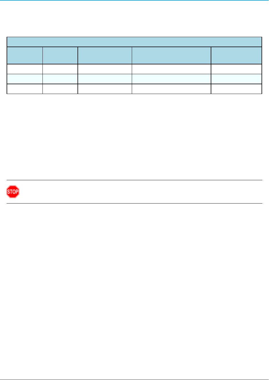
ZumLink Z9-C or Z9-T Included Equipment
Qty Description
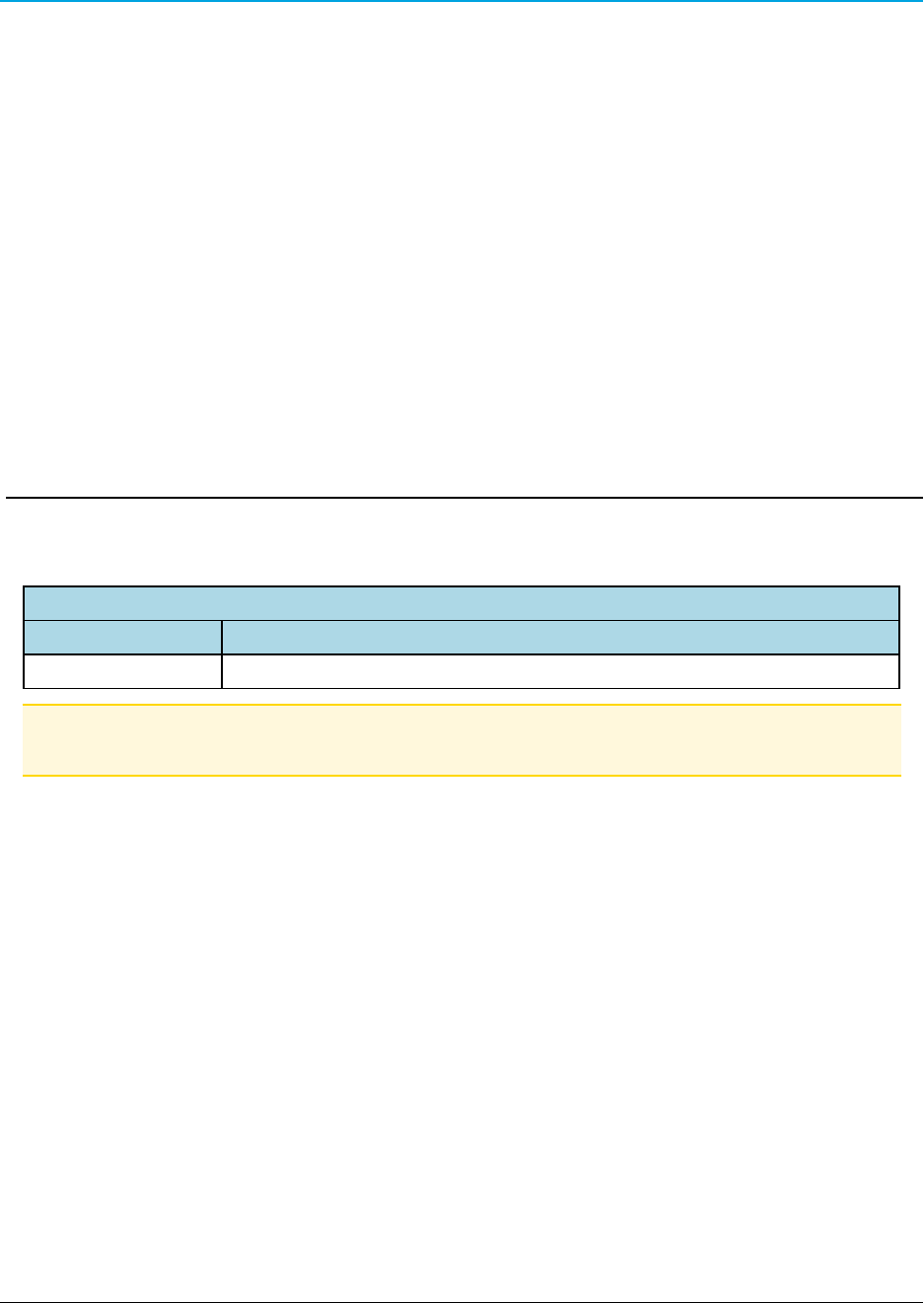
1ZumLink Z9-C or Z9-T device
Note: See Approved Antennas (on page 14) for detailed information.
Approved antennas can be purchased directly from FreeWave.
LUM0075AA Rev May-2016 Page 8 of 40
This document is the property of FreeWave Technologies, Inc. and contains proprietary information owned by
FreeWave. This document cannot be reproduced in whole or in part by any means without written permission from
FreeWave Technologies, Inc.

ZumLink Z9-C or Z9-T: User Manual
2. ZumLink Z9-C or Z9-T CLI Configuration
Important!: A Serial Port on the computer is required for this procedure.
1. Using the Data Interface Connector (see ZumLink Z9-C or Z9-T Data Interface
Connector (on page 16) for location):
a. Apply power to the ZumLink.
b. Connect to the Serial Interface of the ZumLink.
lThe Z9-C model has an RS232 interface and can be connected directly to an
RS232 device.
lFreeWave offers a cable (ASC2414DJ) from the radio to a DB9 connector that
includes a reset button and power input jack.
lThe Z9-T model has a TTL interface and does NOT work directly with RS232.
lIf connecting up to a device or circuit that is RS232, a circuit is required to adapt
between the two interfaces.
2. If the ZumLink is connected to a computer, open a terminal program (e.g., Tera Term).
Note: In this example procedure, Tera Term is used.
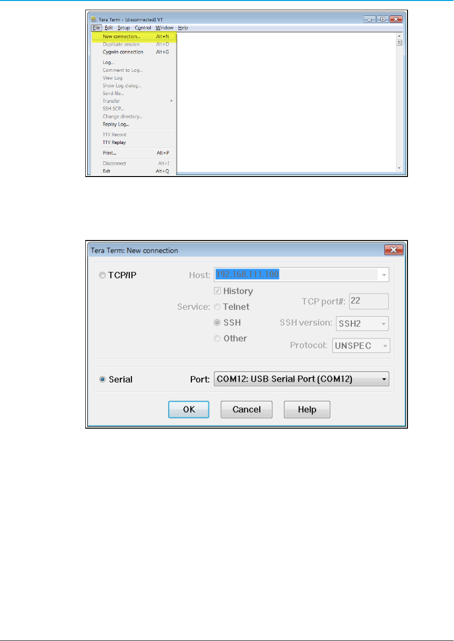
3. In Tera Term, on the File menu, select New Connection.
LUM0075AA Rev May-2016 Page 9 of 40
This document is the property of FreeWave Technologies, Inc. and contains proprietary information owned by
FreeWave. This document cannot be reproduced in whole or in part by any means without written permission from
FreeWave Technologies, Inc.
2. ZumLink Z9-C or Z9-T CLI Configuration
Page 10 of 40 LUM0075AA Rev May-2016
This document is the property of FreeWave Technologies, Inc. and contains proprietary information owned by
FreeWave. This document cannot be reproduced in whole or in part by any means without written permission from
FreeWave Technologies, Inc.
Figure 1: File menu > New Connection
The Tera Term New Connection dialog box opens.
4. Click the Port list box arrow and select the COM port the ZumLink device is connected to.
Figure 2: Select the ZumLink COM port
5. Click OK to save the changes and close the dialog box.
The Tera Term window shows the connected COM port and Baud rate in the title bar of the
window.
6. In the Tera Term window, click the Setup menu and select Serial Port.
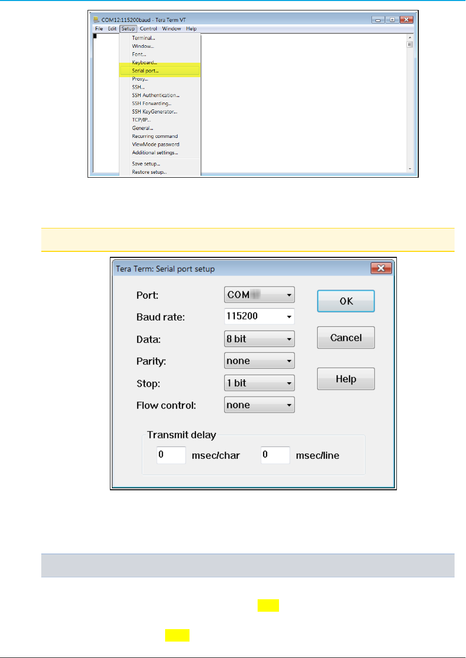
ZumLink Z9-C or Z9-T: User Manual
Figure 3: Serial menu > Setup Port
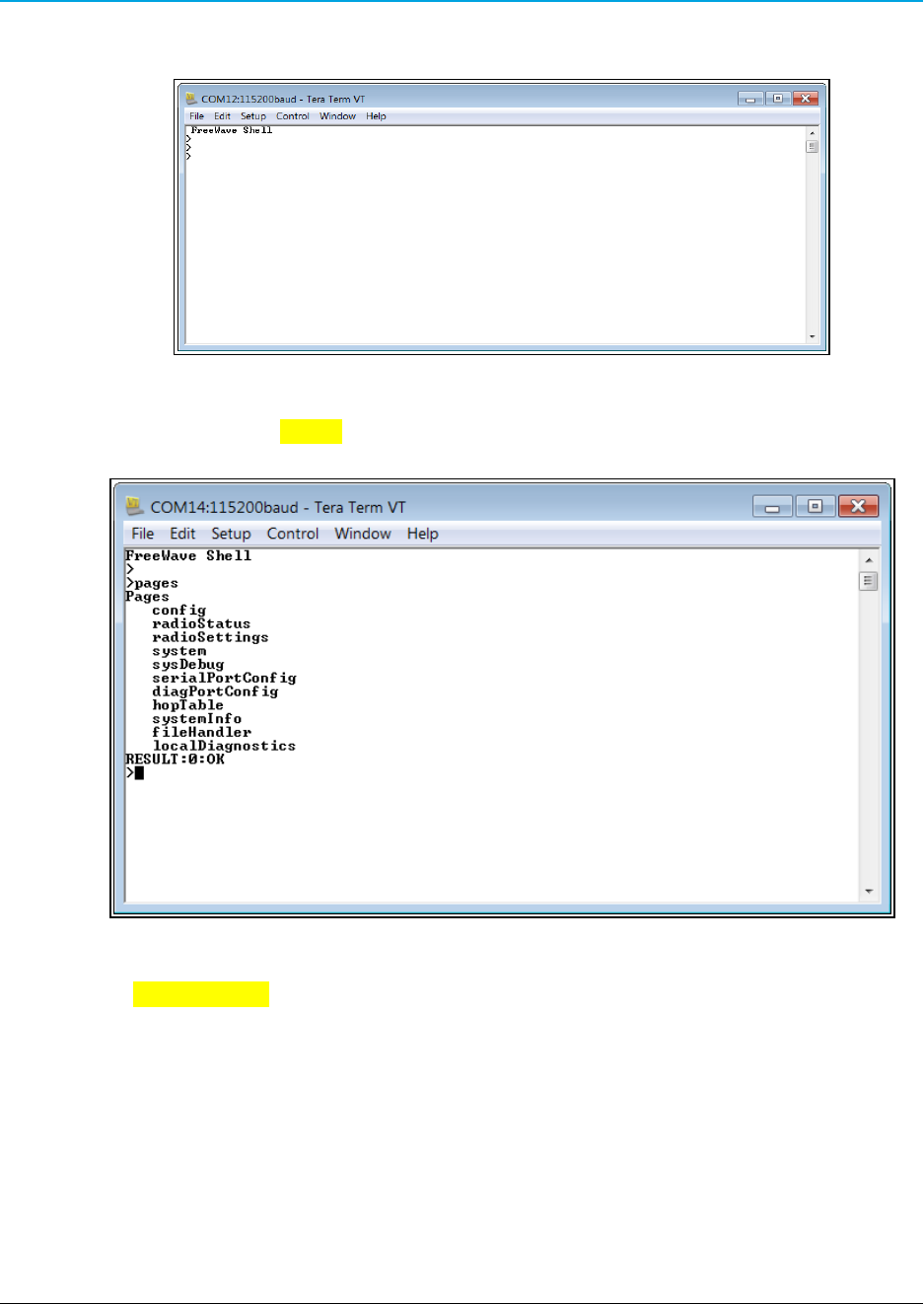
The Tera Term: Serial Port Setup dialog box opens.
Note: The image shows the default ZumLink settings.
Figure 4: Tera Term: Serial Port Setup dialog box with default settings
7. Verify, and change if required, the Tera Term serial port settings (except the Port setting)
of the connected ZumLink so the settings are the same as the defaults shown in the image.
Example: If the Baud Rate is 9600, click the list box arrow and select 115200.
8. Click OK to save the changes and close the dialog box.
9. On the ZumLink, pull the Pin 2-Interrupt line Low to activate the FreeWave Shell and
disrupt data flow.
10. Return Pin 2-Interrupt to High.
LUM0075AA Rev May-2016 Page 11 of 40
This document is the property of FreeWave Technologies, Inc. and contains proprietary information owned by
FreeWave. This document cannot be reproduced in whole or in part by any means without written permission from
FreeWave Technologies, Inc.
2. ZumLink Z9-C or Z9-T CLI Configuration
Page 12 of 40 LUM0075AA Rev May-2016
This document is the property of FreeWave Technologies, Inc. and contains proprietary information owned by
FreeWave. This document cannot be reproduced in whole or in part by any means without written permission from
FreeWave Technologies, Inc.
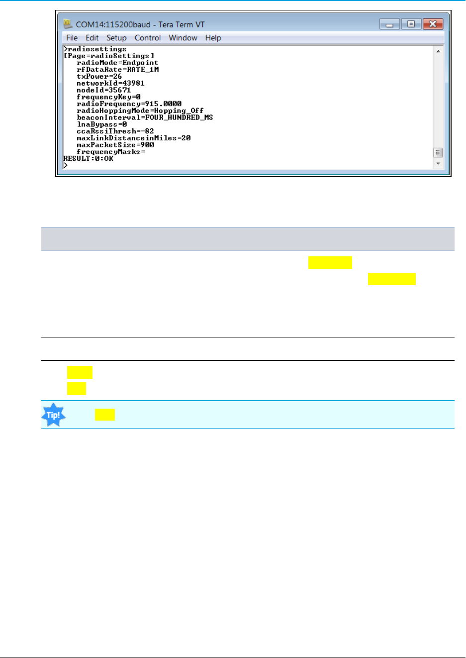
11. In Tera Term, press <Enter>.
The FreeWave Shell returns.
Figure 5: FreeWave Shell in Tera Term
12. At the > prompt, type pages and press <Enter>.
The available ZumLink information appears.
Figure 6: Pages information
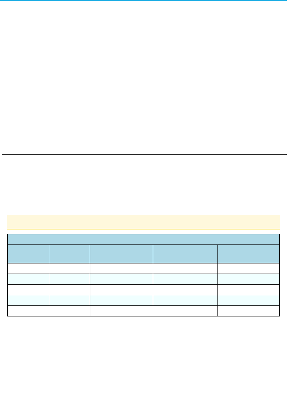
13. Type radiosettings and press <Enter>.
The ZumLink radioSettings appear.
ZumLink Z9-C or Z9-T: User Manual
Figure 7: ZumLink radioSettings
14. Set the radioSettings.txPower between 10 and 30.
Example:txPower=30 or radioSettings.txPower=30.
15. Select one radio and set the radioSettings.radioMode=Gateway.
16. Set the other radios in the network with a radioSettings.radioMode=Endpoint.
17. Set the radioSettings.networkId to be the same on all radios in the network.
18. On each Endpoint, set the radioSettings.nodeId to a unique number (between 2 and
65533) in the network.
Important!: The Gateway radioSettings.nodeId defaults to 1 and CANNOT be changed.
19. Type Save (for the settings to remain after a power cycle) and press <Enter>.
20. Type exit and press <Enter> to exit the FreeWave Shell.
Type help to view additional information about the ZumLink settings.
LUM0075AA Rev May-2016 Page 13 of 40
This document is the property of FreeWave Technologies, Inc. and contains proprietary information owned by
FreeWave. This document cannot be reproduced in whole or in part by any means without written permission from
FreeWave Technologies, Inc.
ZumLink Z9-C or Z9-T: User Manual
3. Approved Antennas
3.1 900MHz Antennas
3.1.1 900MHz Omni-Directional Antennas
The ZumLink 900MHz is approved by the FCC for use with omni-directional antennas with a
10.5dBi gain or less.
Note: These antennas, including antenna gains, are approved for use with the ZumLink device.
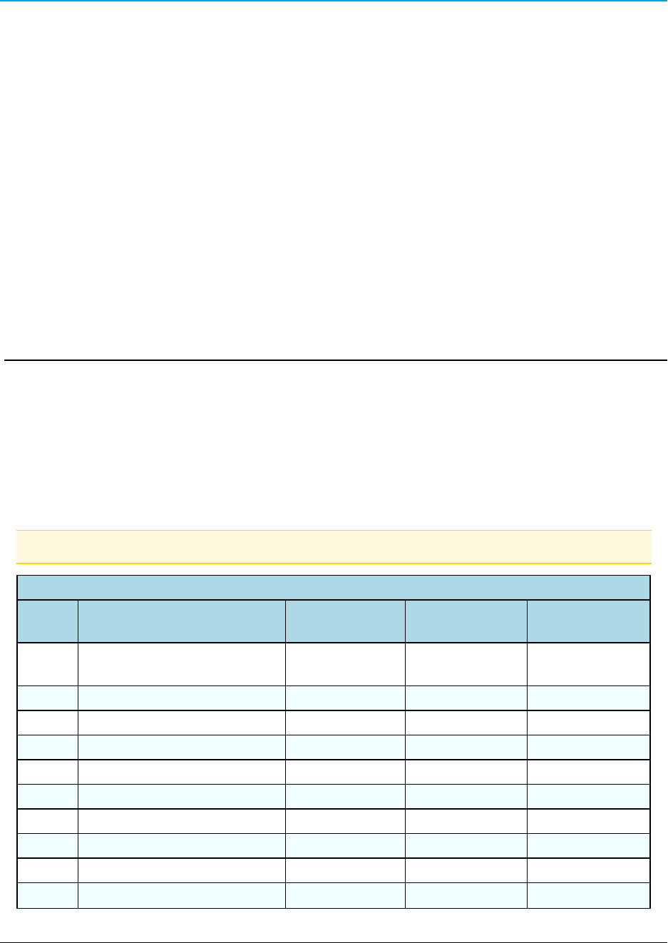
900MHz Omni-Directional Antennas
Gain (dBd) Gain (dBi) Manufacturer Manufacturer
Model Number
FreeWave
Part Number
5.00 7.15 Antenex EB8965C EAN0905WC
3 5.15 Maxrad MAX-9053 EAN0900WC
-0.15 2.0 Mobile Mark PSKN3-925S EAN0900SR
-2.15 0 Mobile Mark PSTG0-915SE EAN0900SQ
8.35 10.5 Hana Wireless HW-OD9-11-NF
LUM0075AA Rev May-2016 Page 14 of 40
This document is the property of FreeWave Technologies, Inc. and contains proprietary information owned by
FreeWave. This document cannot be reproduced in whole or in part by any means without written permission from
FreeWave Technologies, Inc.
3. Approved Antennas
Page 15 of 40 LUM0075AA Rev May-2016
This document is the property of FreeWave Technologies, Inc. and contains proprietary information owned by
FreeWave. This document cannot be reproduced in whole or in part by any means without written permission from
FreeWave Technologies, Inc.
3.1.2 900MHz Directional Antennas
The ZumLink 900MHz is approved by the FCC for use with Yagi directional antennas with a gain
or less.
900MHz Directional Antennas
Gain (dBd) Gain (dBi) Manufacturer Manufacturer
Model Number
FreeWave
Part Number
5.85 8.0 WaveLink PRO898-8
6.45 8.6 WaveLink PRO890-8-40F02N4 EAN0906YC
13.85 16.0 WaveLink PRO890‐16‐40F02N4
3.1.3 Alternative Antennas
Antennas other than those listed in this section can potentially be used with the ZumLink with
provisions.
lThe antennas must be of a similar type.
lThe antenna gain CANNOT exceed 10.5dBi for Omni-directional.
lThe antenna gain CANNOT exceed 16.0dBi for Directional antennas.
lThe overall system EIRP does not exceed 36dBm.
Warning! A proper combination with the ZumLink is required to ensure the system meets
FCC requirements.
ZumLink Z9-C or Z9-T: User Manual
4. ZumLink Z9-C or Z9-T Data Interface Connector
lThe ZumLink Z9-C or Z9-T includes a 14-pin header for power input, data input and
output, diagnostics, and configuration.
lThis 14-pin header:
lis equivalent to the Samtec TMM-107-01-G-D-SM-A.
lmates with Samtec CLT, SQT, SQW, ESQT, TLE, SMM, MMS, and TCSD style
connectors.
Note: FreeWave defines TTL as 0 (zero) to 3.3VDC.
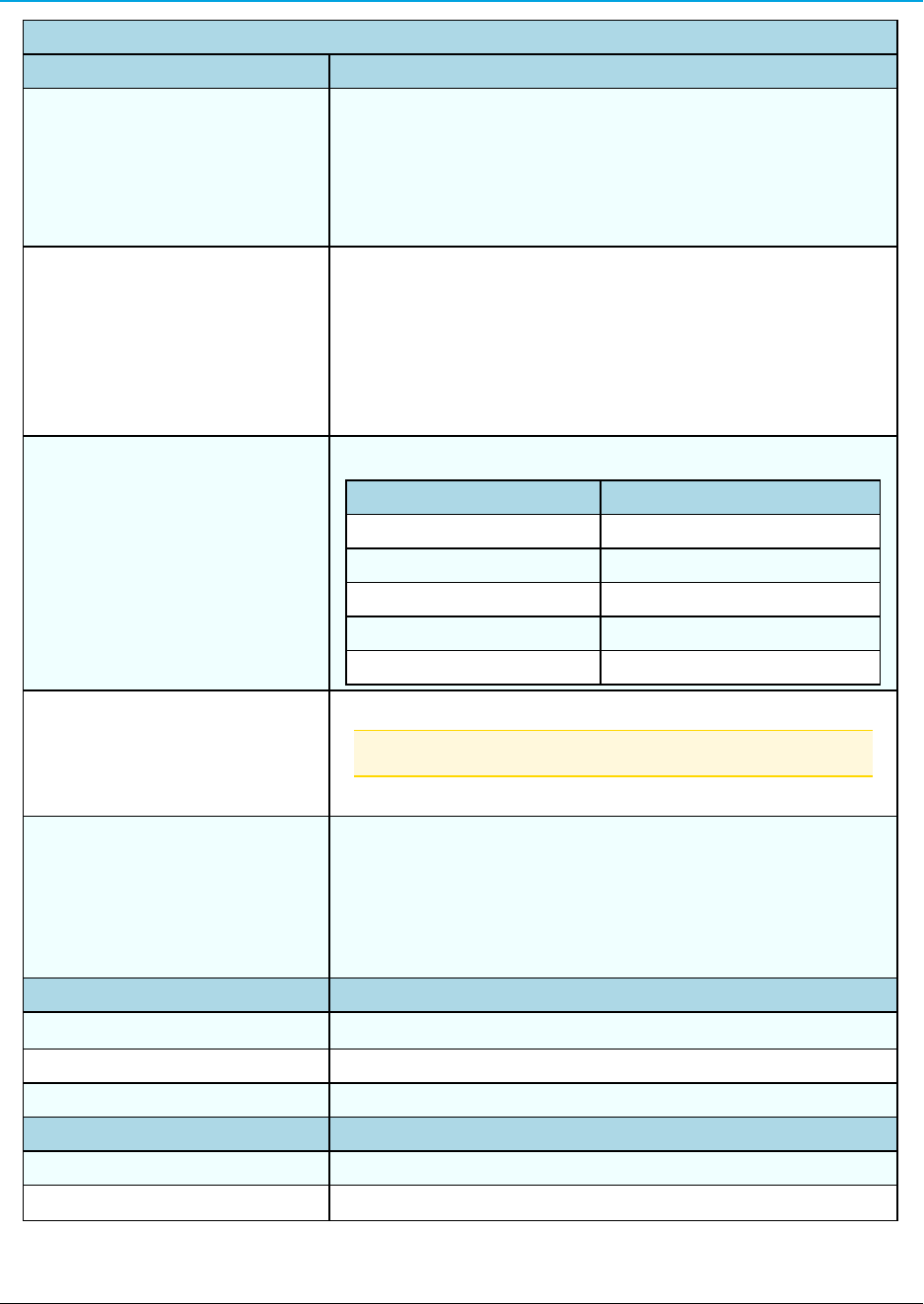
ZumLink Z9-C or Z9-T Data Interface Connector
Pin # Signal Description and
Name
Radio Input /
Output
Z9-C
Signal Level
Z9-T
Signal Level
1 Power (B+) Input +3 to +5VDC
(±10%)
+3 to +5VDC
(±10%)
2 Interrupt Input TTL TTL
3 Data Terminal Ready (DTR) Input RS-232 TTL
4 Ground (GND) N/A
5 Transmitted Data (TXD) Output RS-232 TTL
6 Radio Reset Input TTL TTL
7 Received Data (RXD) Input RS-232 TTL
8 Carrier Detect (CD) Output RS-232 TTL
9 Request To Send (RTS) Input RS-232 TTL
10 Clear To Send (CTS) Output RS-232 TTL
LUM0075AA Rev May-2016 Page 16 of 40
This document is the property of FreeWave Technologies, Inc. and contains proprietary information owned by
FreeWave. This document cannot be reproduced in whole or in part by any means without written permission from
FreeWave Technologies, Inc.
4. ZumLink Z9-C or Z9-T Data Interface Connector
Page 17 of 40 LUM0075AA Rev May-2016
This document is the property of FreeWave Technologies, Inc. and contains proprietary information owned by
FreeWave. This document cannot be reproduced in whole or in part by any means without written permission from
FreeWave Technologies, Inc.
ZumLink Z9-C or Z9-T Data Interface Connector
Pin # Signal Description and
Name
Radio Input /
Output
Z9-C
Signal Level
Z9-T
Signal Level
11 Diagnostic Received Data
(Diag RX)
Input RS-232 TTL
12 Diagnostic Transmitted Data
(Diag TX)
Output RS-232 TTL
13 Ground (GND) N/A
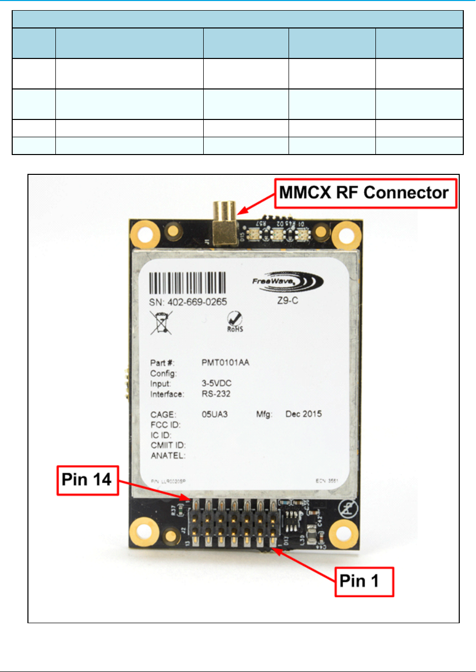
14 Unused N/A
Figure 8: ZumLink Z9-C or Z9-T MMCX RF Connector,
Pin 1, and Pin 14 of Data Interface Connector

5. ZumLink Z9-C or Z9-T Settings and Descriptions
These are the Page Settings for the ZumLink Z9-C or Z9-T:
lconfig (on page 19)
ldiagPortConfig (on page 20)
lradioSettings (on page 22)
lradioStatus (on page 33)
lserialPortConfig (on page 34)
lsystem (on page 35)
lsystemInfo (on page 36)
LUM0075AA Rev May-2016 Page 18 of 40
This document is the property of FreeWave Technologies, Inc. and contains proprietary information owned by FreeWave. This document cannot be reproduced
in whole or in part by any means without written permission from FreeWave Technologies, Inc.
5. ZumLink Z9-C or Z9-T Settings and Descriptions
Page 19 of 40 LUM0075AA Rev May-2016
This document is the property of FreeWave Technologies, Inc. and contains proprietary information owned by FreeWave. This document cannot be reproduced
in whole or in part by any means without written permission from FreeWave Technologies, Inc.
Note: If the "=" sign is appended to the parameter, it is an implied change to that parameter.
If a value is NOT included after the "=", the value becomes a null, space, or 0 (zero) depending on the parameter.
Example: Entering txPower returns the current value of txPower.
Entering txPower= is an implied change to txPower.
If a value is NOTincluded, it changes txPower to 10.
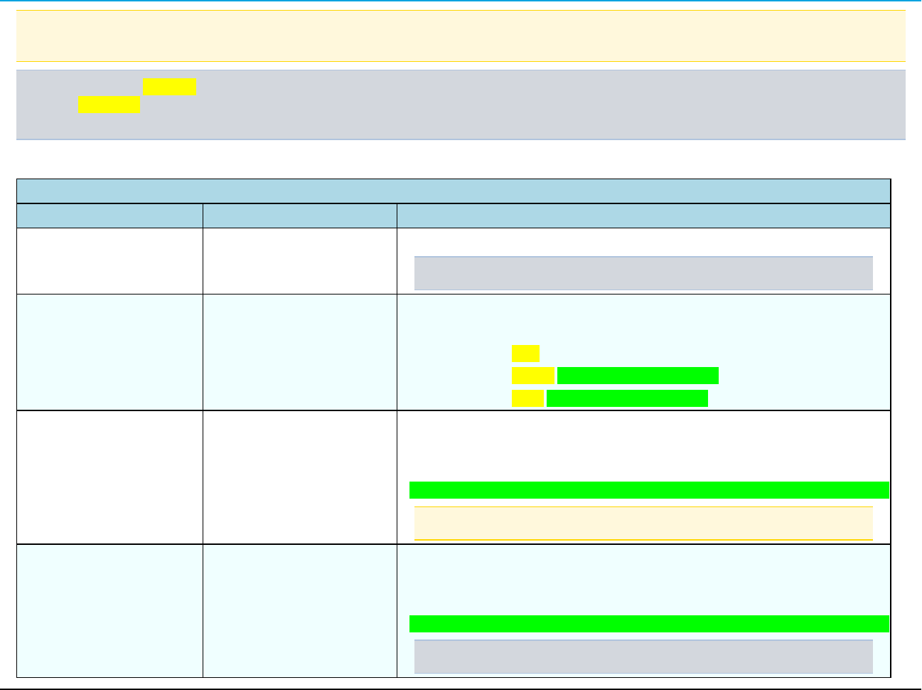
config
config - ZumLink Settings and Descriptions
Page CLI Command Description
[Page=config] config.factoryDefaults= This setting restores the ZumLink to its factory default configuration.
Example:config.factoryDefaults=set
[Page=config] config.reset= All options reset the ZumLink Z9-C or Z9-T.
The options are:
lconfig.reset=now
lconfig.reset=reboot is this valid? John to verify
lconfig.reset=reset is this valid? John to verify
[Page=config] config.restore= This setting reloads the config settings of the ZumLink that were saved.
Phil asks: What are the options?
Note: Restore happens automatically when the ZumLink starts.
[Page=config] config.save= This setting saves changes made to the ZumLink configuration.
Phil asks: Is NOW the only option? I think one option is config.save=1.
Example:config.save=now
ZumLink Z9-C or Z9-T
diagPortConfig
diagPortConfig - ZumLink Settings and Descriptions
Page CLI Command Description
[Page=diagPortConfig] diagPortConfig.cliBaudRate= This setting sets the baud rate for the diagnostic port.
The options are:
lWhat are the options here?
l
l
l
Note: The default value is 115200.
[Page=diagPortConfig] diagPortConfig.databits= This setting defines the byte length for the diagnostic port.
The options are:
l7 bits
l8 bits
Note: The default value is 8.
[Page=diagPortConfig] diagPortConfig.diagBaudRate=
Note: The default value is 115200.
LUM0075AA Rev May-2016 Page 20 of 40
This document is the property of FreeWave Technologies, Inc. and contains proprietary information owned by FreeWave. This document cannot be reproduced
in whole or in part by any means without written permission from FreeWave Technologies, Inc.
5. ZumLink Z9-C or Z9-T Settings and Descriptions
Page 21 of 40 LUM0075AA Rev May-2016
This document is the property of FreeWave Technologies, Inc. and contains proprietary information owned by FreeWave. This document cannot be reproduced
in whole or in part by any means without written permission from FreeWave Technologies, Inc.
diagPortConfig - ZumLink Settings and Descriptions
Page CLI Command Description
[Page=diagPortConfig] diagPortConfig.diagMode=
The options are:
lPacketized
lWhat other options are there?
l
l
Note: The default value is Diag.
[Page=diagPortConfig] diagPortConfig.parity= This setting defines the parity for the diagnostic port.
The options are:
lOdd
lEven
lNone
Note: The default value is None.
[Page=diagPortConfig] diagPortConfig.stopbits= This setting defines the number of stop bits for the diagnostic port.
The options are:
lNone
l1
l2
Note: The default value is 1.
ZumLink Z9-C or Z9-T
radioSettings
radioSettings - ZumLink Settings and Descriptions
Page CLI Command Description
[Page=radioSettings] radioSettings.beaconInterval= Note: This setting is only available when Frequency Hopping is
enabled.
The beaconInterval controls how often a Gateway radio sends out a
beacon packet and changes to the next radio frequency in the hopping
pattern.
lA longer beaconInterval gives the system better throughput in
channel environments where interference is minimal.
lThroughput can be improved in some situations with shorter beacon
intervals.
Important!: The Endpoint radios will obtain this value from a
Gateway with the same networkId.
Editing this value when the radioMode is set to Endpoint will
return an OK; HOWEVER, the value will become what the
Gateway is set to as soon as it processes a received beacon.
The options are:
lTWENTY_FIVE_MS
lFIFTY_MS
lONE_HUNDRED_MS
lTWO_HUNDRED_MS
lFOUR_HUNDRED_MS
Example:radioSettings.beaconInterval=FIFTY_MS.
Note: The default value is FOUR_HUNDRED_MS.
LUM0075AA Rev May-2016 Page 22 of 40
This document is the property of FreeWave Technologies, Inc. and contains proprietary information owned by FreeWave. This document cannot be reproduced
in whole or in part by any means without written permission from FreeWave Technologies, Inc.
5. ZumLink Z9-C or Z9-T Settings and Descriptions
Page 23 of 40 LUM0075AA Rev May-2016
This document is the property of FreeWave Technologies, Inc. and contains proprietary information owned by FreeWave. This document cannot be reproduced
in whole or in part by any means without written permission from FreeWave Technologies, Inc.
radioSettings - ZumLink Settings and Descriptions
Page CLI Command Description
[Page=radioSettings] radioSettings.ccaRssiThresh=- This parameter uses the receive signal strength to determine if there is
a signal on the radio before transmission.
Note: The default value is -82.
[Page=radioSettings] radioSettings.frequencyKey= Note: This setting is only available when Frequency Hopping is
enabled.
The Frequency Key is a number used as an index to select a hopping
table.
Note: The Endpoint radios will obtain this value from a Gateway
with the same networkId.
lThe Frequency Key setting boundaries are 0 (zero) to 31.
lWhen a hop table loads, the Frequency Key is adjusted to
whatever is available in the actual hop table.
lAn invalid frequency setting is determined by being outside of the
specified range.
lIf an invalid frequency setting is found, the Frequency Key is
NOT changed.
lA frequency setting can also be invalid if the Frequency Key setting
is larger than the number of hopping tables for a specific rfDataRate.
lIn that case, the Frequency Key is set to 0 (zero).
lThe options are Key0 (zero) to Key23.
Note: The default value is Key0 (zero).
ZumLink Z9-C or Z9-T
radioSettings - ZumLink Settings and Descriptions
Page CLI Command Description
[Page=radioSettings] radioSettings.frequencyMasks= Frequency Masks are used to mask off frequencies or a set of
frequencies in a hop table.
Single Channel Format
lfrequencyMasks=xxx.yyyy,xxx.yyyy,xxx.yyyy.
Example: frequencyMasks=903.0000,908.0000,925.0000.
Range of Channels Format
lfrequencyMasks=xxx.yyyy-xxx.yyyy,xxx.yyyy.
Example: frequencyMasks=902.1000-905.1000,920.1000-
927.9000
Combination of Channels Format
lfrequencyMasks=902.1000-905.1000,920.1000-
927.9000,915.0200
Where:
lxxx is a value between 902-927.
lyyyy is a value between .0000-.9999.
Note: Least significant digits are not required.
Example: .9, .09, .009 are valid entries.
Important!: Frequency mask entries MUST BE less than 128
bytes.
A comma MUST separate the values - NOT a comma and a
space.
LUM0075AA Rev May-2016 Page 24 of 40
This document is the property of FreeWave Technologies, Inc. and contains proprietary information owned by FreeWave. This document cannot be reproduced
in whole or in part by any means without written permission from FreeWave Technologies, Inc.

5. ZumLink Z9-C or Z9-T Settings and Descriptions
Page 25 of 40 LUM0075AA Rev May-2016
This document is the property of FreeWave Technologies, Inc. and contains proprietary information owned by FreeWave. This document cannot be reproduced
in whole or in part by any means without written permission from FreeWave Technologies, Inc.
radioSettings - ZumLink Settings and Descriptions
Page CLI Command Description
Example: A single entry such as 904.0 masks off any
frequencies using 904.0 as a center frequency along with any
bandwidth on each side of the center frequency as a function of
rfDataRate.
A frequency range such as 904.0-906.9999 masks off any
frequencies in the range of 904.0 minus the bandwidth associated
with the data rate, through 906.9999 plus the bandwidth
associated with the data rate.
ZumLink Z9-C or Z9-T
radioSettings - ZumLink Settings and Descriptions
Page CLI Command Description
[Page=radioSettings] radioSettings.frequencyMasks=
(continued)
lErrors occur when masking reduces the number of frequencies
below regulatory minimums.
lFor channel sizes < 500kHz, the radio must frequency hop.
lThis does NOT apply for channel sizes greater than 500 kHz
which can operate single channel or frequency hopping.
lIf the radioSettings.rfDataRate=RATE_250K:
lIf the number of hopping channels is >= 50, the maximum
txPower is 30dBm.
lIf the number of channels is 25 to 49, the maximum txPower is
24dBm.
lIf the number of hopping channels contained in the hop table is <
25, all masking is removed and all of the channels contained in
the hop table are re-enabled and txPower is NOT changed.
lIf the radioSettings.rfDataRate=RATE_115.2K:
lIf the number of hopping channels is >= 50, the maximum
txPower is 30dBm.
lIf the number of hopping channels contained in the hop table is <
50, all masking is removed and all of the channels contained in
the hop table are re-enabled and txPower is NOT changed.
Notes
lBoth Gateway and Endpoint radios MUST use the same value for
the frequencyMasks setting.
lIf the frequencyMasks comes back empty see
frequencyMasksErrors for any errors.
lUse frequencyMasks=1 to clear the frequency Masks.
John asks if there's another way to do this clearing?
Note: The default value is Blank.
LUM0075AA Rev May-2016 Page 26 of 40
This document is the property of FreeWave Technologies, Inc. and contains proprietary information owned by FreeWave. This document cannot be reproduced
in whole or in part by any means without written permission from FreeWave Technologies, Inc.
5. ZumLink Z9-C or Z9-T Settings and Descriptions
Page 27 of 40 LUM0075AA Rev May-2016
This document is the property of FreeWave Technologies, Inc. and contains proprietary information owned by FreeWave. This document cannot be reproduced
in whole or in part by any means without written permission from FreeWave Technologies, Inc.
radioSettings - ZumLink Settings and Descriptions
Page CLI Command Description
[Page=radioSettings] radioSettings.lnaBypass= The lnaBypass setting controls enabling and disabling the Low Noise
Amplifier (LNA) which can boost the receive signal by 10dB.
lThe options are 0 (zero) and 1.
lWhen the lnaBypass=1, the LNA of the radio module is
bypassed.
lIf lnaBypass=0, the LNA is enabled.
lIf lnaBypass=<anything but 0> it is set to 1.
It can be useful to bypass the LNA if there is a presence of
strong signals in band and packet reception is not good.
Note: The default value is 0 (zero).
[Page=radioSettings] radioSettings.maxLinkDistanceinMiles= The maxLinkDistanceinMiles setting controls the maximum one-way
distance (in miles) between any node in the network.
Important!: All nodes in the network that communicate with each
other should use the same distance value.
lThe minimum value is 0 (zero) miles.
lThe maximum value is 120 miles.
Note: The default value is 20 miles.
ZumLink Z9-C or Z9-T
radioSettings - ZumLink Settings and Descriptions
Page CLI Command Description
[Page=radioSettings] radioSettings.maxPacketSize= John asks: Can this really be set from the CLI
John says this CANNOT be changed in Thor A
is this other content applicable to Thor B?
Note: This is a ZumLink Golden Setting.
lThe options are any number between 0 and 9.
lMax packet size can be optimized.
FreeWave Recommends: Use the default settings for normal
operation.
[Page=radioSettings] radioSettings.networkId= Note: This is a ZumLink Golden Setting.
This is the Network Identifier. The networkId setting is used to
subdivide traffic on radio units.
lRadio units can only communicate with other units that have the
same networkId setting.
Note: If radios are on the same frequency they will still receive
data from radios of a different networkId, but the data is dropped.
Enter any number between 0 and 65535.
Note: The default value is 43981.
LUM0075AA Rev May-2016 Page 28 of 40
This document is the property of FreeWave Technologies, Inc. and contains proprietary information owned by FreeWave. This document cannot be reproduced
in whole or in part by any means without written permission from FreeWave Technologies, Inc.
5. ZumLink Z9-C or Z9-T Settings and Descriptions
Page 29 of 40 LUM0075AA Rev May-2016
This document is the property of FreeWave Technologies, Inc. and contains proprietary information owned by FreeWave. This document cannot be reproduced
in whole or in part by any means without written permission from FreeWave Technologies, Inc.
radioSettings - ZumLink Settings and Descriptions
Page CLI Command Description
[Page=radioSettings] radioSettings.nodeId= Important!: Each radio with the same networkId must have a
UNIQUE nodeId.
lThis setting defines the ID of the radio.
lThe Gateway device will always have a nodeId of value 1.
lEnter any number between 2 and 65533.
Note: The default value is a unique number between 2 and 65533
for an Endpoint.
ZumLink Z9-C or Z9-T
radioSettings - ZumLink Settings and Descriptions
Page CLI Command Description
[Page=radioSettings] radioSettings.radioFrequency= Note: This is a ZumLink Golden Setting.
This setting designates the Operating Center Frequency in MHz.
lThe radioFrequency parameter ONLY takes effect when
radioHoppingMode=Hopping_Off.
lAll radios in a network must have the same frequency.
lIf the radioFrequency parameter is set too close to the band edge
for the current rfDataRate, the radio module will reject the setting.
Read back this value after setting it to determine if it was
accepted by the radio module.
Valid boundaries are:
l4M data rate: 904.5504 - 925.7472 MHz
l1M data rate: 903.0528 - 927.0144 MHz
l500K data rate: 902.7072 - 927.3600 MHz
l250K data rate: 902.5344 - 927.4176 MHz
l115.2K data rate: 902.4768 - 927.5904 MHz
Note: The default value is 915.0000.
LUM0075AA Rev May-2016 Page 30 of 40
This document is the property of FreeWave Technologies, Inc. and contains proprietary information owned by FreeWave. This document cannot be reproduced
in whole or in part by any means without written permission from FreeWave Technologies, Inc.
5. ZumLink Z9-C or Z9-T Settings and Descriptions
Page 31 of 40 LUM0075AA Rev May-2016
This document is the property of FreeWave Technologies, Inc. and contains proprietary information owned by FreeWave. This document cannot be reproduced
in whole or in part by any means without written permission from FreeWave Technologies, Inc.
radioSettings - ZumLink Settings and Descriptions
Page CLI Command Description
[Page=radioSettings] radioSettings.radioHoppingMode= Note: This is a ZumLink Golden Setting.
The radioHoppingMode parameter is used to enable or disable
frequency hopping.
Important!: The Gateway and Endpoint radios MUST use the
same value for this setting.
lFor rfDataRate values >= 500kbps, the choice of hopping mode
should be selected based on network frequency planning and
channel conditions.
lFor rfDataRate values < 500kbs, radioHoppingMode is forced On.
The options are:
lHopping_Off
lHopping_On
Example:radioSettings.radioHoppingMode=Hopping_On.
Note: The default value is Hopping_Off.
[Page=radioSettings] radioSettings.radioMode= This setting designates the device as a Gateway or Endpoint unit.
lEach network MUST have only ONE Gateway unit.
lThe remaining units MUST be configured as Endpoints.
lThe Gateway device will always have a nodeId of value 1.
lA Gateway is only needed when Frequency Hopping is enabled.
lA Gateway is NOT required when operating with a single channel.
Note: The default value is Endpoint.
ZumLink Z9-C or Z9-T
radioSettings - ZumLink Settings and Descriptions
Page CLI Command Description
[Page=radioSettings] radioSettings.rfDataRate= Note: This is a ZumLink Golden Setting.
This setting defines the RF link data rate speed in bits per second.
lA higher RF link data rate provides more throughput at the expense
of link distance or fade margin.
lWhen changing from lower data rates to higher ones (e.g., RATE_
115.2K to RATE_1M), the radioFrequency may be set back to
915.000 MHz if the signal would have been out of band.
lThe communication range is dependent on the rfDataRate setting.
lThe min value increases and the max value decreases as the
rfDataRate increases.
lThe increase of channel bandwidth affects these ranges.
Important!: The Gateway and Endpoint radios MUST use the
same value for this setting.
The options are:
lRATE_4M
lRATE_1M
lRATE_500K
lRATE_250K
lRATE_115.2K
Note: The default value is RATE_1M.
LUM0075AA Rev May-2016 Page 32 of 40
This document is the property of FreeWave Technologies, Inc. and contains proprietary information owned by FreeWave. This document cannot be reproduced
in whole or in part by any means without written permission from FreeWave Technologies, Inc.
5. ZumLink Z9-C or Z9-T Settings and Descriptions
Page 33 of 40 LUM0075AA Rev May-2016
This document is the property of FreeWave Technologies, Inc. and contains proprietary information owned by FreeWave. This document cannot be reproduced
in whole or in part by any means without written permission from FreeWave Technologies, Inc.
radioSettings - ZumLink Settings and Descriptions
Page CLI Command Description
[Page=radioSettings] radioSettings.txPower= lThis setting defines the RF output transmit power for the radio.
lA higher power can be used to increase link margin.
lUse a lower transmit power to reduce interference when multiple
radio networks are in close proximity.
lEnter 10 to 30
lAt 250K rfDataRate, if the number of frequencies in the hop table is
>= to 50 after the masks are applied, txPower is limited to 30dB.
lIf the number of frequencies are >= 30, but < 50, txPower is set to
.25 W (24dbm) ONLY if the current setting for txPower is >= 24dB.
Note: The default value is 26.
radioStatus
radioStatus - ZumLink Settings and Descriptions
Page CLI Command Description
[Page=radioStatus] radioStatus.curRssi=- This setting designates the WHAT.
Enter any number between what and what.
Note: The default value is 89.
ZumLink Z9-C or Z9-T
serialPortConfig
serialPortConfig - ZumLink Settings and Descriptions
Page CLI Command Description
[Page=serialPortConfig] serialPortConfig.cliBaudRate= This setting designates the WHAT.
Enter any number between what and what.
The default value is 89.
Caution:reset=now MUST be manually entered into the
command line after the baudRate parameter is defined.
Note: The default value is 115200.
[Page=serialPortConfig] serialPortConfig.packetizedBaudRate= This setting defines the data rate of the serial port when operating in
packetized mode.
Note: The default value is 3000000.
[Page=serialPortConfig] serialPortConfig.passthruBaudRate= This setting defines the data rate of the serial port when operating in
pass through mode.
Note: The default value is 115200.
[Page=serialPortConfig] serialPortConfig.databits= This setting defines the number of data bits per byte for the serial
port.
Note: The default value is 8.
[Page=serialPortConfig] serialPortConfig.parity= This setting defines the parity of the serial port.
Note: The default value is None.
LUM0075AA Rev May-2016 Page 34 of 40
This document is the property of FreeWave Technologies, Inc. and contains proprietary information owned by FreeWave. This document cannot be reproduced
in whole or in part by any means without written permission from FreeWave Technologies, Inc.
5. ZumLink Z9-C or Z9-T Settings and Descriptions
Page 35 of 40 LUM0075AA Rev May-2016
This document is the property of FreeWave Technologies, Inc. and contains proprietary information owned by FreeWave. This document cannot be reproduced
in whole or in part by any means without written permission from FreeWave Technologies, Inc.
serialPortConfig - ZumLink Settings and Descriptions
Page CLI Command Description
[Page=serialPortConfig] serialPortConfig.stopbits= This setting defines the number of stop bits of the serial port.
Note: The default value is 1.
[Page=serialPortConfig] serialPortConfig.flowControl= This setting is used to set the flow control of the serial port..
Note: The default value is Hardware.
[Page=serialPortConfig] serialPortConfig.passthruLatencyMode=
Note: The default value is Auto.
[Page=serialPortConfig] serialPortConfig.passthruLatencyTimer=
Note: The default value is 16.
system
system - ZumLink Settings and Descriptions
Page CLI Command Description
[Page=system] system.exit This setting is used to exit the configuration menu and into normal operation for
transmitting and receiving data.
ZumLink Z9-C or Z9-T
system - ZumLink Settings and Descriptions
Page CLI Command Description
[Page=system] system.serialMode= This setting designates the serial port mode as either passthrough or packetized.
lIn passthough mode, the serial port is used for data or configuration but not at the
same time.
lIn packetized mode, both data and configuration is passed over the serial port
simultaneously within a predefined packet.
Note: The default value is Packetized.
[Page=system] system.pages This command lists all of the pages in the ZumLink Z9-C or Z9-T.
systemInfo
systemInfo - ZumLink Z9-C or Z9-T Settings and Descriptions
Page CLI Command Description
[Page=systemInfo] systemInfo.deviceConfiguration=
Note: The default value is A.
[Page=systemInfo] systemInfo.deviceModel=
[Page=systemInfo] systemInfo.deviceSerialNumber= This setting identifies the serial number of the ZumLink Z9-C or Z9-T.
[Page=systemInfo] systemInfo.FirmwareVersion= This setting identifies the firmware version of the ZumLink Z9-C or Z9-
T.
[Page=systemInfo] systemInfo.hopTableVersion= This setting identifies the Hop Table Version.
LUM0075AA Rev May-2016 Page 36 of 40
This document is the property of FreeWave Technologies, Inc. and contains proprietary information owned by FreeWave. This document cannot be reproduced
in whole or in part by any means without written permission from FreeWave Technologies, Inc.
ZumLink Z9-C or Z9-T: User Manual
Appendix A: ZumLink Z9-C or Z9-T
900MHz Technical Specifications
Note: Specifications may change at any time without notice. For the most up-to-date specifications
information, see the product's data sheet available at www.freewave.com.
ZumLink Z9-C or Z9-T 900MHz Technical Specifications
Specification Description
Interfaces
Data Connector lZ9-C - RS-232, Dual row 14-pin header, 2mm pin spacing
lZ9-T - TTL, Dual row 14-pin header, 2mm pin spacing
Serial Interface - Baud Rates lRS-232: 9600 to 921,600 bps
lTTL: 9600 to 3,000,000 bps
RF Connector MMCX
Transmitter
Frequency Range 902 to 928MHz
Output Power 10mW to 1W
User selectable
Data Link Range 40 miles with clear Line of Sight
Modulation lGFSK
l8-ary FSK
LUM0075AA Rev May-2016 Page 37 of 40
This document is the property of FreeWave Technologies, Inc. and contains proprietary information owned by
FreeWave. This document cannot be reproduced in whole or in part by any means without written permission from
FreeWave Technologies, Inc.
Appendix A: ZumLink Z9-C or Z9-T 900MHz Technical Specifications
Page 38 of 40 LUM0075AA Rev May-2016
This document is the property of FreeWave Technologies, Inc. and contains proprietary information owned by
FreeWave. This document cannot be reproduced in whole or in part by any means without written permission from
FreeWave Technologies, Inc.
ZumLink Z9-C or Z9-T 900MHz Technical Specifications
Specification Description
Channel Sizes l230.4kHz
l345.6kHz
l691.2kHz
l1382.4kHz
l3225.6kHz
RF Data Rate l115.2kbps
l250kbps
l500kbps
l1000kbps
l4000kbps
lUser selectable
Hopping Channels User selectable
Data Rate (kbps) Hopping Channels
115.2 110
250 73
500 36
1000 18
4000 7
Hopping Patterns Maximum of 16 patterns
Note: There are less with larger channel bandwidths.
User selectable
Hopping Rates l25ms
l50ms
l100ms
l400ms
User selectable
Receiver
Sensitivity -106 dBm @ 115.2kbps for BER 10-4
IF Selectivity >40dB
System Gain Maximum of 136dB
Data Transmission
Error Detection CRC, FEC, and ARQ
Link Throughput 2000kbps
ZumLink Z9-C or Z9-T: User Manual
ZumLink Z9-C or Z9-T 900MHz Technical Specifications
Specification Description
Data Encryption AES 128
Protocol Proprietary CSMA
Power Requirements
Operating Voltage +3 to +5VDC (±10%)
Tx Current l1230 mA @ 3VDC
l680 mA @ 5VDC
Rx Current l30 mA @ 3VDC
l13 mA @ 5VDC
Idle Current l30 mA @ 3VDC
l13 mA @ 5VDC
General Information
Operating Temperature Range -40 °C to +85 °C
-40° F to 185° F
Humidity 0 to 95% non-condensing
Dimensions 50.8mm Long x 35.56mm Wide x 9.65mm High
2" Long x 1.4" Wide x 0.38" High
Weight 15g
0.53oz
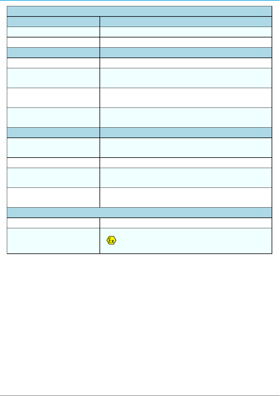
Product Safety
Standards EN 60079-0:2012 + A11:2013 and EN 60079-15:2010
Labeling Information
II 3 GExnAIICT6Gc
DEMKO 16 ATEX 1705X
LUM0075AA Rev May-2016 Page 39 of 40
This document is the property of FreeWave Technologies, Inc. and contains proprietary information owned by
FreeWave. This document cannot be reproduced in whole or in part by any means without written permission from
FreeWave Technologies, Inc.