FreeWave Technologies PRW5000AA Wireless 802.11ac/b/g/n access point User Manual My
FreeWave Technologies Inc. Wireless 802.11ac/b/g/n access point My
Contents
- 1. User Manual
- 2. User Manual User Notifications
User Manual

Part Number: LUM0073AA
Revision: Aug-2015
WP201 Access Point
User Manual

Safety Information
The products described in this manual can fail in a variety of modes due to misuse, age, or malfunction. Systems
with these products must be designed to prevent personal injury and property damage during product operation
and in the event of product failure.
Warning! Do not remove or insert the Ethernet or diagnostics cable while circuit is live unless
the area is known to be free of ignition concentrations of flammable gasses or vapors.
Warranty
FreeWave Technologies, Inc. warrants your FreeWave® Wireless Data Radio against defects in materials and
manufacturing for a period of one year from the date of shipment, depending on model number. In the event of a
Product failure due to materials or workmanship, FreeWave will, at its discretion, repair or replace the Product.
For evaultation of Warranty coverage, return the Product to FreeWave upon receiving a Return Material
Authorization (RMA).
In no event will FreeWave Technologies, Inc., its suppliers, or its licensors be liable for any damages arising from
the use of or inability to use this Product. This includes business interruption, loss of business information, or
other loss which may arise from the use of this Product. OEM customer’s warranty periods can vary.
Warranty Policy will not apply in the following circumstances:
1. If Product repair, adjustments, or parts replacements are required due to accident, neglect, or undue
physical, electrical, or electromagnetic stress.
2. If Product is used outside of FreeWave specifications as stated in the Product's data sheet.
3. If Product has been modified, repaired, or altered by Customer unless FreeWave specifically authorized
such alterations in each instance in writing. This includes the addition of conformal coating.
Special Rate Replacement Option
A special rate replacement option is offered to non-warranty returns or upgrades. The option to purchase the
replacement unit at this special rate is only valid for that RMA. The special replacement rate option expires if not
exercised within 30 days of final disposition of RMA.
FreeWave Technologies, Inc.
5395 Pearl Parkway, Suite 100
Boulder, CO 80301
303.381.9200
Toll Free: 1.866.923.6168
Fax: 303.786.9948
Copyright © 2015 by FreeWave Technologies, Inc.
All rights reserved. www.freewave.com
Page 2 of 38 LUM0073AA Rev Aug-2015
This document is the property of FreeWave Technologies, Inc. and contains proprietary information owned by
FreeWave®. This document cannot be reproduced in whole or in part by any means without written permission from
FreeWave Technologies, Inc.

WP201 Access Point: User Manual
WP201® Return Material Authorization (RMA) Policy and Procedures
This policy describes the responsibilities and procedures of the Customer and FreeWave when a WP201®
device return is required.
When a request for a WP201® device replacement has been validated by FreeWave’s Customer Support,
FreeWave’s policy for processing the device returned due to a fault is to replace the device with a new or
refurbished device upon receipt of the reported faulty product.
Important!: This policy means that a failure analysis on the returned device will NOT be performed and
reported to customers.
Note: This RMA policy is subject to change without notice.
Detailed information about the FreeWave RMA policy can be found at www.freewave.com.
FreeWave Responsibilities
A failed WP201® product is inventoried at FreeWave. If FreeWave experiences a high degree of failures or a
trend, FreeWave will perform a root-cause analysis and take appropriate corrective action(s).
In-Warranty Replacement Procedure
1. Customer contacts FreeWave Customer Support to report the non-functioning WP201® device.
2. FreeWave Customer Support:
a. Validates that a device replacement is the appropriate action.
b. Issues a FreeWave RMA number.
3. The Customer pays the shipping costs to return the WP201® device to FreeWave.
4. FreeWave sends a new or refurbished WP201® device to the Customer.
Important!: Any visual or external damage noted on returned units may void the warranty.
This will be communicated back to the customer and a Purchase Order (PO) will be requested from the
customer for product replacement.
Out-of-Warranty WP201 Replacement
This procedure describes the Customer and FreeWave Customer Support responsibilities for replacing an out-
of-warranty WP201 device.
Procedure
1. Customer contacts FreeWave Customer Support to report the non-functioning WP201® device.
2. FreeWave Customer Support:
a. Validates that the device is out of warranty and if replacement is the appropriate action.
b. Requests a PO number from the Customer (to bill the replacement WP201® device and shipping).
c. Issues a FreeWave RMA number and advises the Customer to return the device to FreeWave.
3. FreeWave:
a. Bills the Customer for the replacement WP201® device and shipping.
b. Sends a new or refurbished WP201® device to the Customer.
Export Notification
FreeWave Technologies, Inc. products may be subject to control by the Export Administration Regulations
(EAR) and/or the International Traffic in Arms Regulations (ITAR). Export, re-export, or transfer of these
products without required authorization from the U.S. Department of Commerce, Bureau of Industry and
Security, or the U.S. Department of State, Directorate of Defense Trade Controls, as applicable, is
prohibited. Any party exporting, re-exporting, or transferring FreeWave products is responsible for
LUM0073AA Rev Aug-2015 Page 3 of 38
This document is the property of FreeWave Technologies, Inc. and contains proprietary information owned by
FreeWave®. This document cannot be reproduced in whole or in part by any means without written permission from
FreeWave Technologies, Inc.

obtaining all necessary U.S. government authorizations required to ensure compliance with these and other
applicable U.S. laws. Consult with your legal counsel for further guidance.
FCC Notifications
This device complies with Part 15 of the FCC rules. Operation is subject to the following two conditions: 1) This
device may not cause harmful interference and 2) this device must accept any interference received, including
interference that may cause undesired operation.
The content of this guide covers FreeWave Technologies, Inc. models sold under FCC ID: TBD.
All models sold under the FCC ID(s) listed above must be installed professionally and are only approved for use
when installed in devices produced by FreeWave Technologies or third party OEMs with the express written
approval of FreeWave Technologies, Inc. Changes or modifications should not be made to the device.
IC Notifications
This device complies with Industry Canada license-exempt RSS standard(s). Operation is subject to the
following two conditions: (1) this device may not cause interference, and (2) this device must accept any
interference, including interference that may cause undesired operation of the device.
Ce dispositif est conforme aux normes permis-exemptes du Canada RSS d'industrie. L'opération est sujette aux
deux conditions suivantes : (1) ce dispositif peut ne pas causer l'interférence, et (2) ce dispositif doit accepter
n'importe quelle interférence, y compris l'interférence qui peut causer le fonctionnement peu désiré du dispositif.
GNU License Notification
Some of the software in the firmware is licensed under the GNU General Public License and other Open Source
and Free Software licenses. You can obtain corresponding source by contacting FreeWave and requesting the
source on CD.
Restricted Rights
Any product names mentioned in this manual may be trademarks or registered trademarks of their respective
companies and are hereby acknowledged.
This manual is only for use by purchasers and other authorized users of FreeWave products.
No part of this manual may be reproduced or transmitted in any form or by any means, electronic or mechanical,
or for any purpose without the express written permission of FreeWave Technologies, Inc. FreeWave reserves
the right to make changes to this manual without notice. FreeWave assumes no responsibility or liability for the
use of this manual or the infringement of any copyright or other proprietary right.
WP201 Product Safety
WP201 Conditions of Safe Use
lProvision shall be made to prevent the rated voltage from being exceeded by the transient
disturbances of more than 140% of the peak rated voltage.
lThe WP201 CANNOT be used in an environment greater than pollution degree 2.
Page 4 of 38 LUM0073AA Rev Aug-2015
This document is the property of FreeWave Technologies, Inc. and contains proprietary information owned by
FreeWave®. This document cannot be reproduced in whole or in part by any means without written permission from
FreeWave Technologies, Inc.

WP201 Access Point: User Manual
Table Of Contents
Preface 7
1. WP201 Overview 9
1.1 System Requirements 10
1.2 User-supplied Equipment 10
1.3 WP201 Included Accessories 11
1.4 WP201 Hardware Layout 13
1.4.1 Front of the WP201 13
1.4.2 Back of the WP201 14
1.4.3 Left Side of the WP201 15
1.4.4 Bottom of the WP201 15
1.4.5 Right Side of the WP201 16
2. WP201 Installation and Setup 17
2.1 Connect to the WP201 Access Point 18
2.2 WP201 IP Address Configuration 19
2.3 Access the WP201 22
2.4 Changing the WP201 Mode 23
2.5 Wall Mounting the WP201 25
2.6 Pole Mounting the WP201 29
Appendix A: WP201 Technical Specifications 35
LUM0073AA Rev Aug-2015 Page 5 of 38
This document is the property of FreeWave Technologies, Inc. and contains proprietary information owned by
FreeWave®. This document cannot be reproduced in whole or in part by any means without written permission from
FreeWave Technologies, Inc.

Page 6 of 38 LUM0073AA Rev Aug-2015
This document is the property of FreeWave Technologies, Inc. and contains proprietary information owned by
FreeWave®. This document cannot be reproduced in whole or in part by any means without written permission from
FreeWave Technologies, Inc.

WP201 Access Point: User Manual
Preface
Where to Find Additional Information
WP201 Quick Start Guide
Use the FreeWave website www.freewave.com to download the latest version of the Quick Start
Guide.
Contacting FreeWave Technical Support
For up-to-date troubleshooting information, check the Support page at www.freewave.com.
FreeWave provides technical support Monday through Friday, 8:00 AM to 5:00 PM Mountain
Time (GMT -7).
lCall toll-free at 1.866.923.6168.
lIn Colorado, call 303.381.9200.
lContact us through e-mail at moreinfo@freewave.com.
Printing this Document
This document is set to print double-sided with a front cover and a back cover. Viewing this
document online with a PDF viewer, may show pages intentionally left blank to accommodate the
double-sided printing.
Document Styles
This document uses these styles:
LUM0073AARev Aug-2015 Page 7 of 38
This document is the property of FreeWave Technologies, Inc. and contains proprietary information owned by
FreeWave®. This document cannot be reproduced in whole or in part by any means without written permission from
FreeWave Technologies, Inc.

Preface
lFreeWave applications appear as: FreeWave.
lParameter setting text appears as: [Page=radioSettings]
lFile names appear as: configuration.cfg.
lFile paths appear as: C:\Program Files (x86)\FreeWave Technologies.
lUser-entered text appears as: xxxxxxxxx.
l3rd-party names appear as: Notepad®.
Caution: Indicates a situation that MAY cause damage to personnel, the radio, data, or
network.
Example: Provides example information of the related text.
FreeWave Recommends: Identifies FreeWave recommendation information.
Important!: Provides semi-cautionary information relevant to the text or procedure.
Note: Emphasis of specific information relevant to the text or procedure.
Provides time saving or informative suggestions about using the product.
Warning! Indicates a situation that WILL cause damage to personnel, the radio, data, or
network.
Documentation Feedback
Send comments or questions about this document's content to techpubs@freewave.com. In the
email, include the title of the document or the document's part number and revision letter (found in
the footer).
Page 8 of 38 LUM0073AA Rev Aug-2015
This document is the property of FreeWave Technologies, Inc. and contains proprietary information owned by
FreeWave®. This document cannot be reproduced in whole or in part by any means without written permission from
FreeWave Technologies, Inc.

WP201 Access Point: User Manual
1. WP201 Overview
Thank you for purchasing the WP201 Access Point.
The FreeWave WP201 is a high-powered, long-range, 3x3 Dual-Band, Wireless,
802.11ac/a/b/g/n Outdoor Access Point. It can be configured as:
lan Access Point.
la Client Bridge.
la Wireless Distribution System (WDS-AP, Station, or Bridge).
The FreeWave WP201:
lis easy to install in almost any location with its PoE (Power over Ethernet) Injector for quick
outdoor installation.
lenables network administrators to control its transmit power and feature settings for
selecting narrow bandwidths and traffic shaping.
lsupports wireless encryption including Wi-Fi Protected Access (WPA-PSK/ WPA2-PSK)
Encryption, and IEEE 802.1x with RADIUS.
The WP201 is designed to operate in a variety of outdoor environments and:
lSupports IEEE 802.11ac/a/b/g/n wireless standards with a maximum speed of:
l450Mbps data rate on a 2.4GHz frequency band under 802.11b/g/n mode.
l1300Mbps data rate on a 5GHz band under 802.11ac/a/n mode for communicating to
and from 5GHz capable computers, tablets or smart phones or transferring files.
LUM0073AARev Aug-2015 Page 9 of 38
This document is the property of FreeWave Technologies, Inc. and contains proprietary information owned by
FreeWave®. This document cannot be reproduced in whole or in part by any means without written permission from
FreeWave Technologies, Inc.

1. WP201 Overview
Example: Several WP201 Access Points can be deployed in a campus setting using the 5GHz
band as a backhaul to provide multiple 2.4GHz wireless cells for computers or mobile devices
in common outdoor areas.
lA maximum of 29dBm transmit power, enabling long range connectivity.
lThere are three detachable:
l5dBi 2.4GHz omni-directional antennas.
l7dBi 5GHz omni-directional antennas.
lMesh Supported (2.4GHz).
l802.3at - capable switches or injectors.
lBand Steering shifts Dual Band clients to 5GHz for better throughput performance.
lSecured Guest Network option available
Notes
lMaximum data rates are based on IEEE 802.11 standards.
lActual throughput and range may vary depending on many factors including environmental
conditions, distance between devices, radio interference in the operating environment, and
mix of devices in the network.
lFeatures and specifications are subject to change without notice.
lTrademarks and registered trademarks are the property of their respective owners.
1.1 System Requirements
These are the system requirements needed to configure the WP201:
lComputer with:
lan Ethernet interface or wireless network capability
lWindows® 7 or greater, Mac OS, or Linux-based operating systems.
lBroadband Internet Service (Cable or DSL Modem)
lWeb browser (i.e., Internet Explorer, Firefox, Safari, Chrome).
1.2 User-supplied Equipment
lComputer with Windows® 7 or greater
lQty-2: CAT5e Ethernet cables without strain relief
Page 10 of 38 LUM0073AA Rev Aug-2015
This document is the property of FreeWave Technologies, Inc. and contains proprietary information owned by
FreeWave®. This document cannot be reproduced in whole or in part by any means without written permission from
FreeWave Technologies, Inc.

WP201 Access Point: User Manual
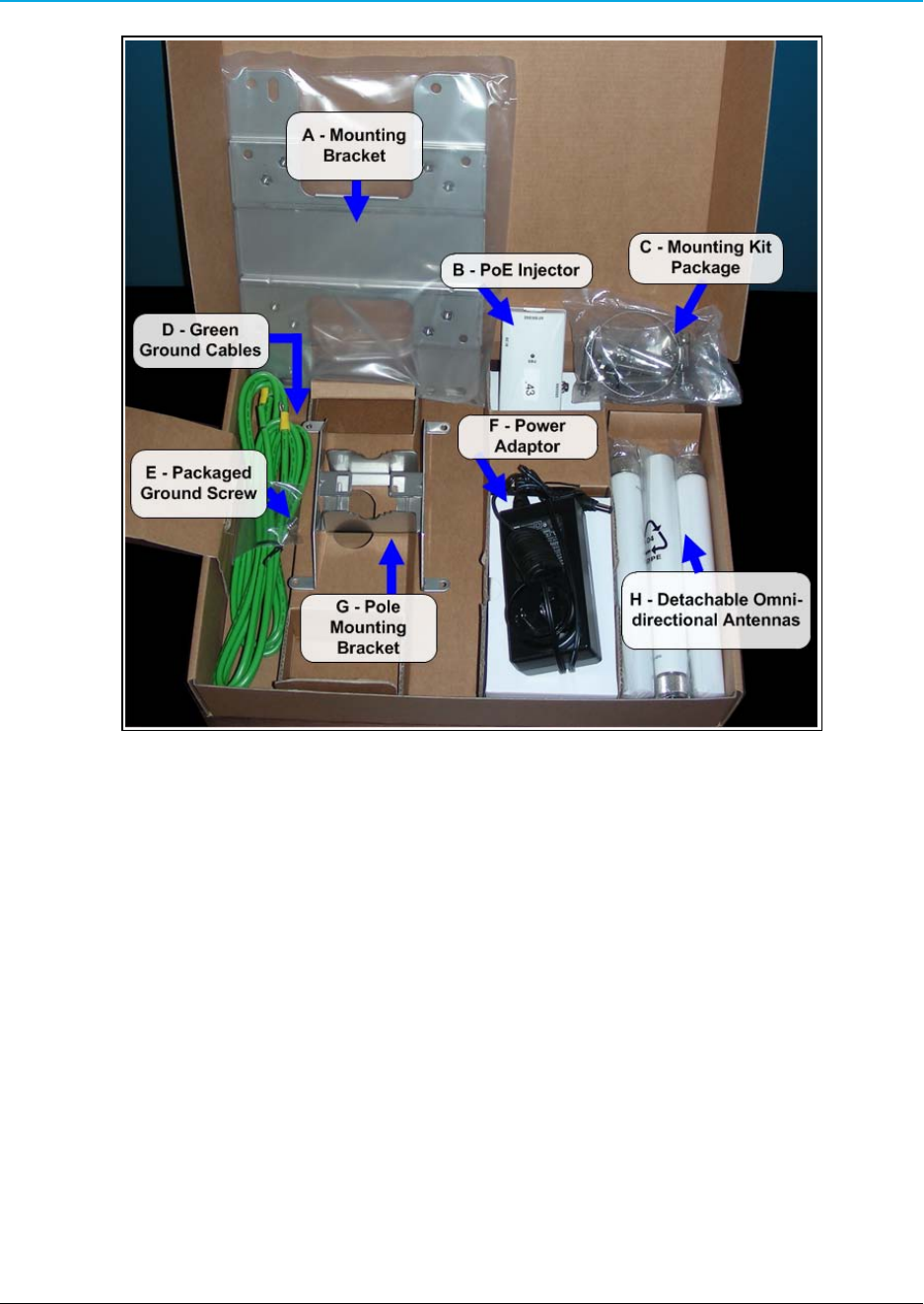
1.3 WP201 Included Accessories
The WP201 package contains these items:
WP201 Included Accessories
Qty Description Image
Letter
1WP201 Access Point
1WP201 Quick Start Guide
1 Mounting Bracket A
1 PoE Injector B
1 Mounting Kit Package (hex cap screws, washers, wall anchors and bolts, ring
clamp)
C
2 Green Ground Cables D
1 Packaged Ground Screw E
1 Power Adapter F
1 Pole Mounting Bracket G
3 Detachable 7dBi 5GHz omni-directional antennas H
3 Detachable 5dBi 2.4GHz omni-directional antennas H
Important!: ALL items must be returned to issue a refund.
LUM0073AA Rev Aug-2015 Page 11 of 38
This document is the property of FreeWave Technologies, Inc. and contains proprietary information owned by
FreeWave®. This document cannot be reproduced in whole or in part by any means without written permission from
FreeWave Technologies, Inc.
1. WP201 Overview
Figure 1: WP201 Included Accessories
Page 12 of 38 LUM0073AA Rev Aug-2015
This document is the property of FreeWave Technologies, Inc. and contains proprietary information owned by
FreeWave®. This document cannot be reproduced in whole or in part by any means without written permission from
FreeWave Technologies, Inc.
WP201 Access Point: User Manual
1.4 WP201 Hardware Layout
These images identify the hardware layout of the WP201.
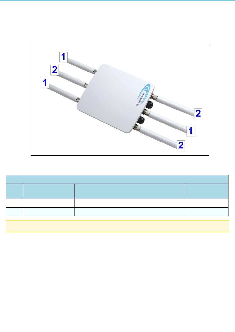
1.4.1 Front of the WP201
Figure 2: Front of the WP201
Front of the WP201
# Name Description Accessory
Location***
1 2.4 GHz Antennas Detachable 5 dBi 2.4 GHz omni-directional H
2 5 GHz Antennas Detachable 7 dBi 5 GHz omni-directional H
Note: ***See WP201 Included Accessories (on page 11).
LUM0073AA Rev Aug-2015 Page 13 of 38
This document is the property of FreeWave Technologies, Inc. and contains proprietary information owned by
FreeWave®. This document cannot be reproduced in whole or in part by any means without written permission from
FreeWave Technologies, Inc.
1. WP201 Overview
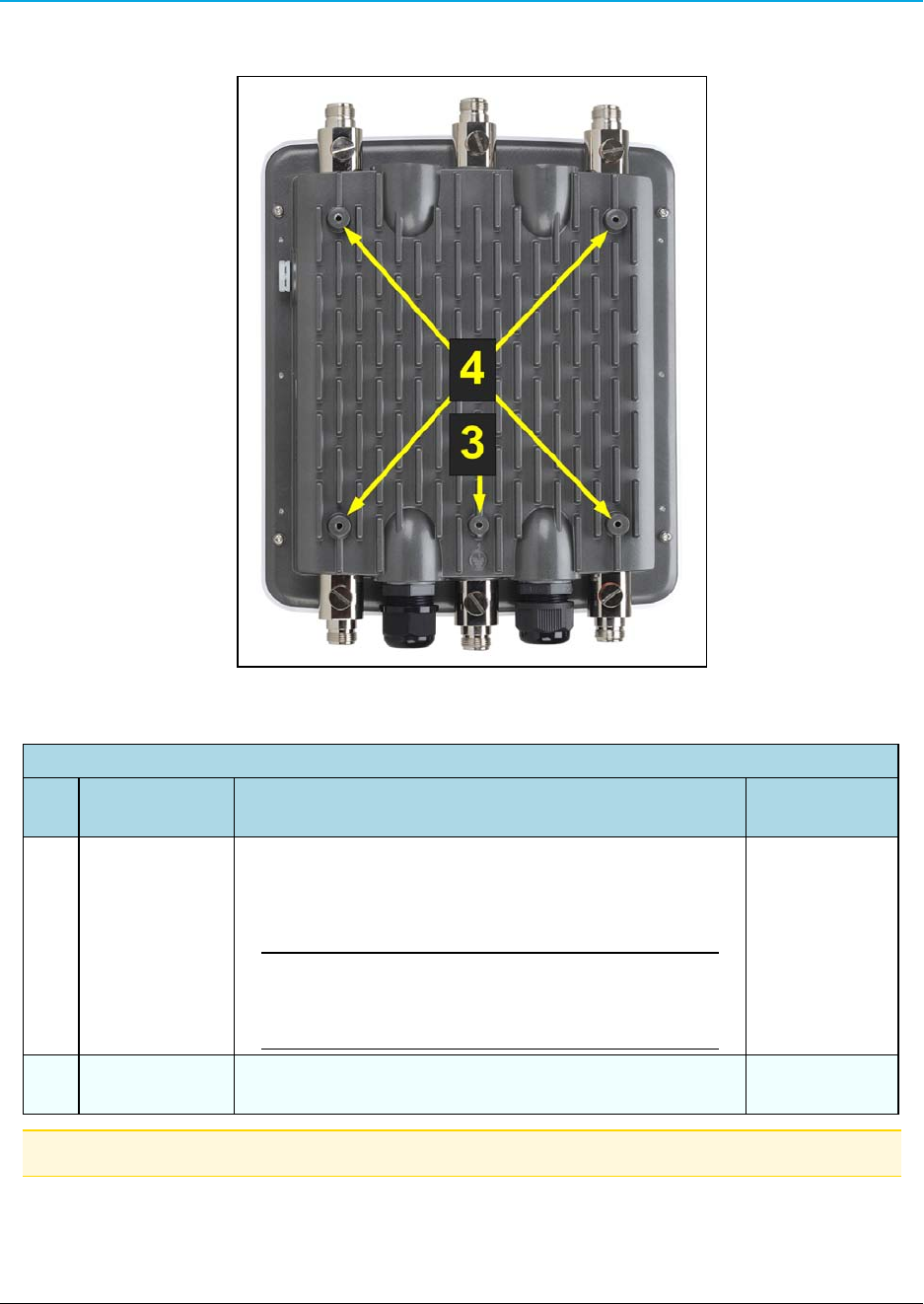
1.4.2 Back of the WP201
Figure 3: Back of the WP201
Back of the WP201
# Name Description Accessory
Location***
3 Ground screw
hole
Using the enclosed Packaged Ground Screw, attach
the loop end of one of the supplied Green Ground
Cables to the ground point on the Back of the WP201 (on
page 14).
Important!: The Green Ground Cable MUST BE
attached to the WP201 BEFORE the Mounting
Bracket is attached.
E
4 Mounting
Holes
The Mounting Holes are used to attach the Mounting
Bracket to the WP201.
A
Note: ***See WP201 Included Accessories (on page 11).
Page 14 of 38 LUM0073AA Rev Aug-2015
This document is the property of FreeWave Technologies, Inc. and contains proprietary information owned by
FreeWave®. This document cannot be reproduced in whole or in part by any means without written permission from
FreeWave Technologies, Inc.
WP201 Access Point: User Manual
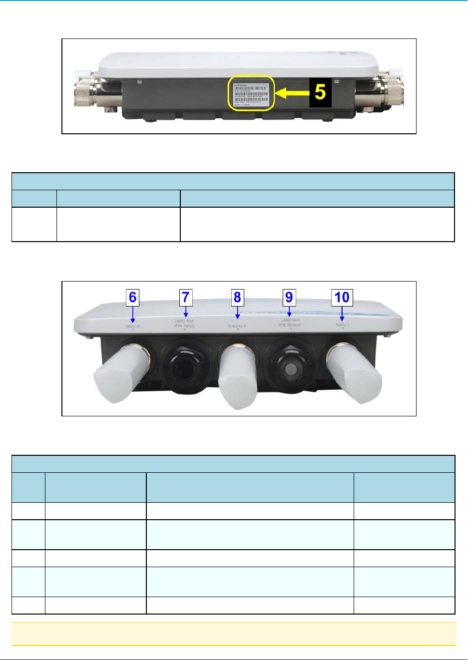
1.4.3 Left Side of the WP201
Figure 4: Left Side of the WP201
Left Side of the WP201
# Name Description
5 Serial Number label The Serial Number of the WP201 is 10 digits:
l123-456-7890
1.4.4 Bottom of the WP201
Figure 5: Bottom of the WP201
Bottom of the WP201
# Name Description Accessory
Location***
6 5GHz Antenna Detachable 7 dBi 5 GHz omni-directional H
7 LAN Port 1 (PoE
Input)
802.3at Ethernet port for RJ-45 cable.
8 2.4GHz Antenna Detachable 5 dBi 2.4 GHz omni-directional H
9 LAN Port 2 (PSE
Output)
802.3af Ethernet port for RJ-45 cable.
10 5GHz Antenna Detachable 7 dBi 5 GHz omni-directional H
Note: ***See WP201 Included Accessories (on page 11).
LUM0073AA Rev Aug-2015 Page 15 of 38
This document is the property of FreeWave Technologies, Inc. and contains proprietary information owned by
FreeWave®. This document cannot be reproduced in whole or in part by any means without written permission from
FreeWave Technologies, Inc.
1. WP201 Overview
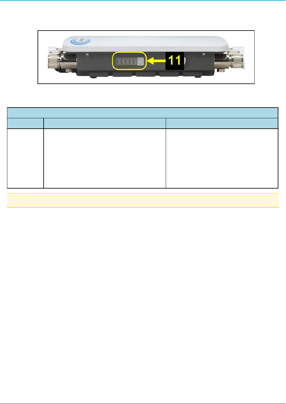
1.4.5 Right Side of the WP201
Figure 6: Right of the WP201
Front of the WP201
# Name Description
11 LED Indicators: LED lights The LEDs are:
lPower
lLAN Port 1
lLAN Port 2
l2.4 GHz Connection
l5 GHz Connection
Note: ***See WP201 Included Accessories (on page 11).
Page 16 of 38 LUM0073AA Rev Aug-2015
This document is the property of FreeWave Technologies, Inc. and contains proprietary information owned by
FreeWave®. This document cannot be reproduced in whole or in part by any means without written permission from
FreeWave Technologies, Inc.

WP201 Access Point: User Manual
2. WP201 Installation and Setup
This section provides procedure information about installation and initial setup of the WP201.
lConnect to the WP201 Access Point (on page 18).
lWP201 IP Address Configuration (on page 19).
lAccess the WP201 (on page 22).
lChanging the WP201 Mode (on page 23).
lWall Mounting the WP201 (on page 25).
lPole Mounting the WP201 (on page 29).
LUM0073AARev Aug-2015 Page 17 of 38
This document is the property of FreeWave Technologies, Inc. and contains proprietary information owned by
FreeWave®. This document cannot be reproduced in whole or in part by any means without written permission from
FreeWave Technologies, Inc.
2. WP201 Installation and Setup
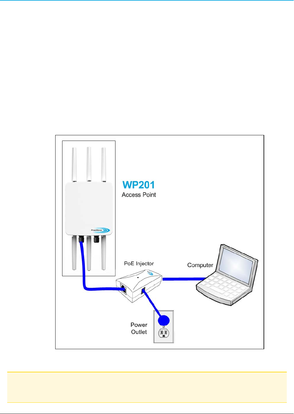
2.1 Connect to the WP201 Access Point
1. Attach and gently tighten the provided antennas to the appropriate port on the WP201.
2. Attach one of the supplied Green Ground Cables to the Ground screw on the PoE
Injector.
3. Attach the other end of the Green Ground Cable to a weather-proof ground.
4. Using one of the CAT5e Ethernet cables, connect one end of the cable to the LAN 1 Port
(PoE Input) of the WP201 and the other end into the AP/Bridge port on the PoE Injector.
5. Connect the second CAT5e Ethernet cable to the Network port of the PoE Injector and
the other end to the computer Ethernet port.
6. Connect the Power Adapter to the DC IN port of the PoE Injector and plug the other end
into an electrical outlet.
Figure 7: Connecting the WP201 Access Point
Note: The WP201 can be powered through the LAN 1 Port (PoE Input) by any PSE (Power Sourcing
Equipment) which supports IEEE802.11at (PoE+) including the provided PoE Injector. With adequate
input power, the WP201 can power a device connected to the LAN 2 Port (PSE Output).
Page 18 of 38 LUM0073AA Rev Aug-2015
This document is the property of FreeWave Technologies, Inc. and contains proprietary information owned by
FreeWave®. This document cannot be reproduced in whole or in part by any means without written permission from
FreeWave Technologies, Inc.
WP201 Access Point: User Manual
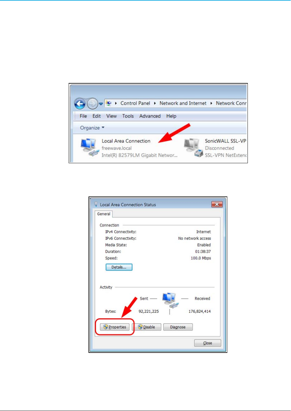
2.2 WP201 IP Address Configuration
1. Turn on the computer.
2. Click the Windows® Start button and select Control Panel.
3. Click Network and Internet > View Network Status and Tasks.
4. Click the Change adapter settings link.
5. Double-click the Local Area Connection link.
Figure 8: Local Area Connection link
The Local Area Connection Status dialog box opens.
Figure 9: Local Area Connection Status dialog box
6. Click Properties.
The Local Area Connection Properties dialog box opens.
7. Select the Internet Protocol Version 4 (TCP/IPv4) option.
LUM0073AA Rev Aug-2015 Page 19 of 38
This document is the property of FreeWave Technologies, Inc. and contains proprietary information owned by
FreeWave®. This document cannot be reproduced in whole or in part by any means without written permission from
FreeWave Technologies, Inc.
2. WP201 Installation and Setup
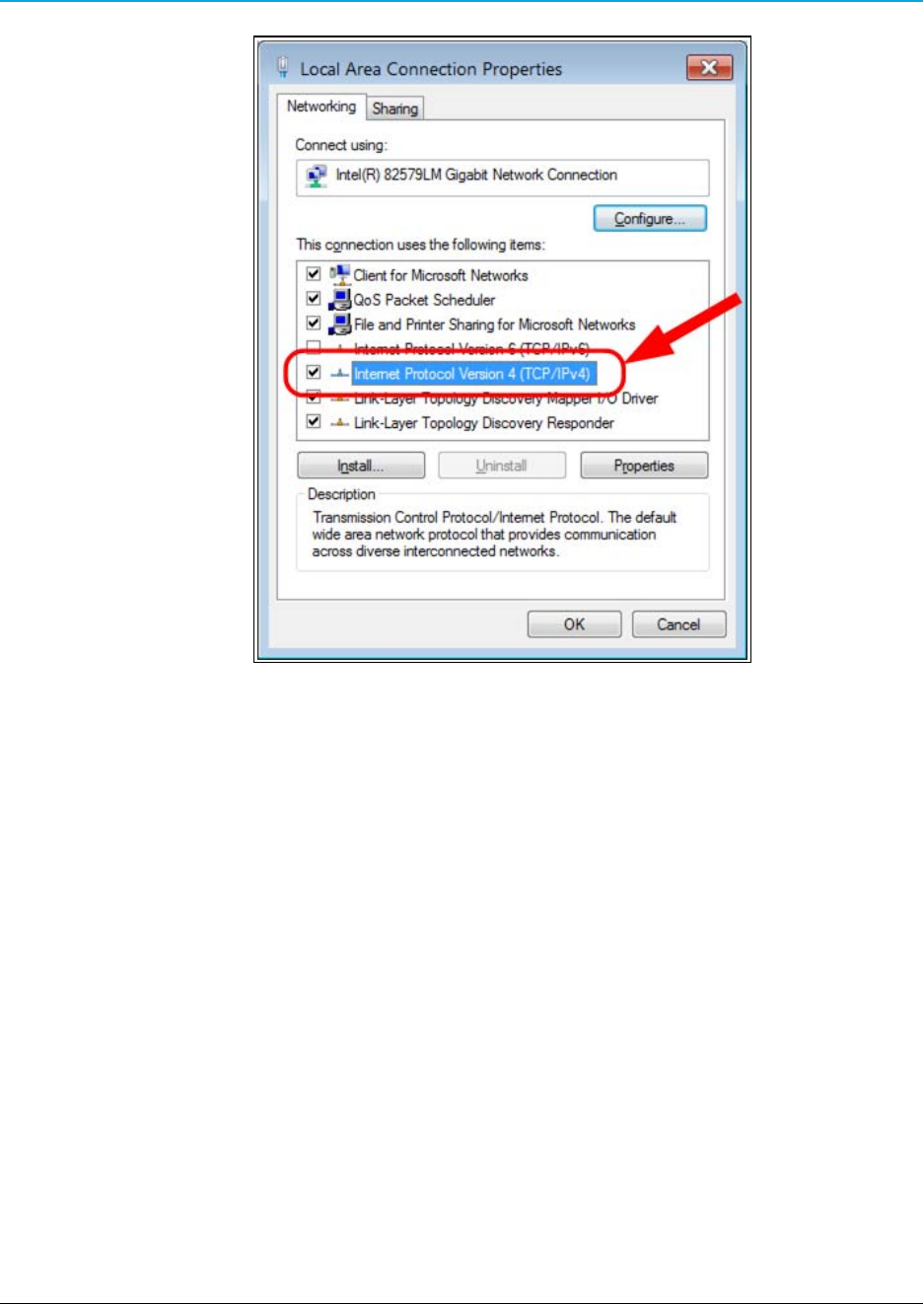
Figure 10: Local Area Connection Properties dialog box
8. Click Properties.
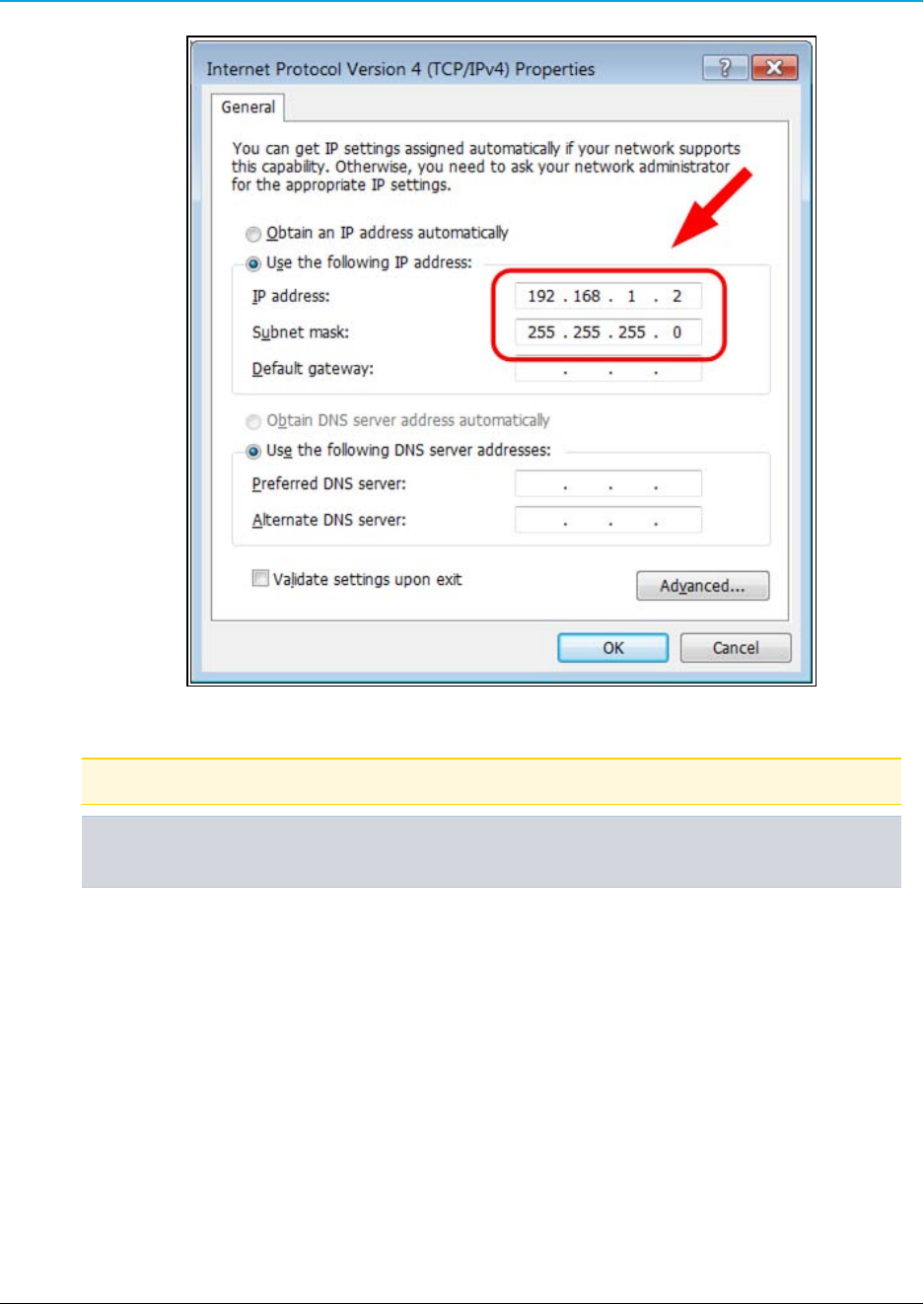
The Internet Protocol Version 4 (TCP/IPv4) Properties dialog box opens.
9. Select the Use the following IP address option button.
10. In the IP Address text box, enter an IP Address that is DIFFERENT from the WP201.
Page 20 of 38 LUM0073AA Rev Aug-2015
This document is the property of FreeWave Technologies, Inc. and contains proprietary information owned by
FreeWave®. This document cannot be reproduced in whole or in part by any means without written permission from
FreeWave Technologies, Inc.
WP201 Access Point: User Manual
Figure 11: Local Area Connection Properties dialog box
Note: The default WP201 IP Address is 192.168.1.1.
Example: Enter an IP Address from 192.168.1.2 to 192.168.1.254 and the Subnet Mask to
255.255.255.0.
11. Click OK to save the changes and close the dialog box.
12. Click Close twice to close the Local Area Connection Properties and Local Area
Connection Status dialog boxes.
LUM0073AA Rev Aug-2015 Page 21 of 38
This document is the property of FreeWave Technologies, Inc. and contains proprietary information owned by
FreeWave®. This document cannot be reproduced in whole or in part by any means without written permission from
FreeWave Technologies, Inc.
2. WP201 Installation and Setup
2.3 Access the WP201
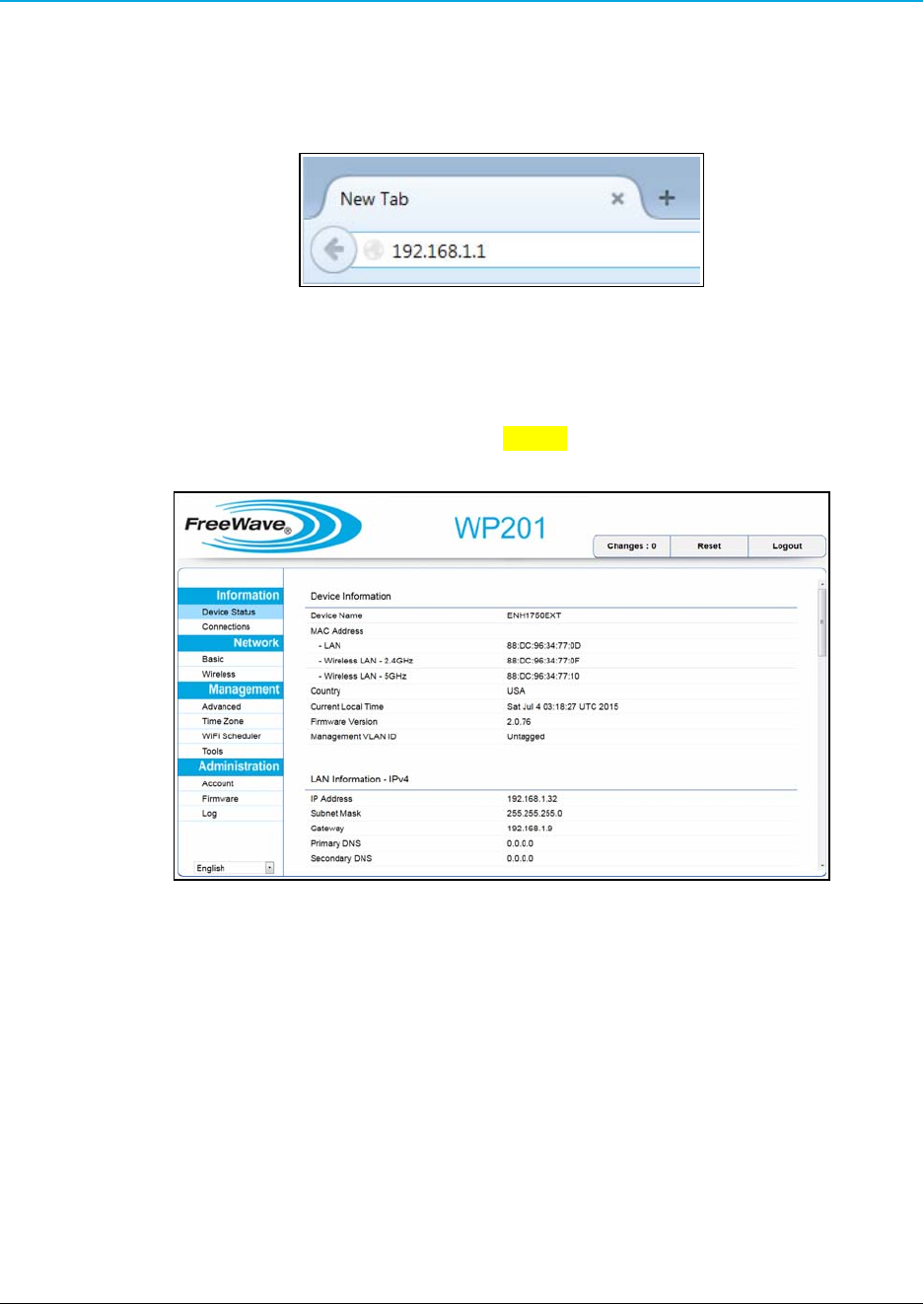
1. Open a web browser.
2. In the address bar of the browser, enter 192.168.1.1.
Figure 12: Entered IP Address
3. Press <Enter>.
The Login dialog box opens.
4. Enter the default Username and Password (admin for both) and click Login.
The Device Information window opens.
Figure 13: Device Information window
Page 22 of 38 LUM0073AA Rev Aug-2015
This document is the property of FreeWave Technologies, Inc. and contains proprietary information owned by
FreeWave®. This document cannot be reproduced in whole or in part by any means without written permission from
FreeWave Technologies, Inc.
WP201 Access Point: User Manual
2.4 Changing the WP201 Mode
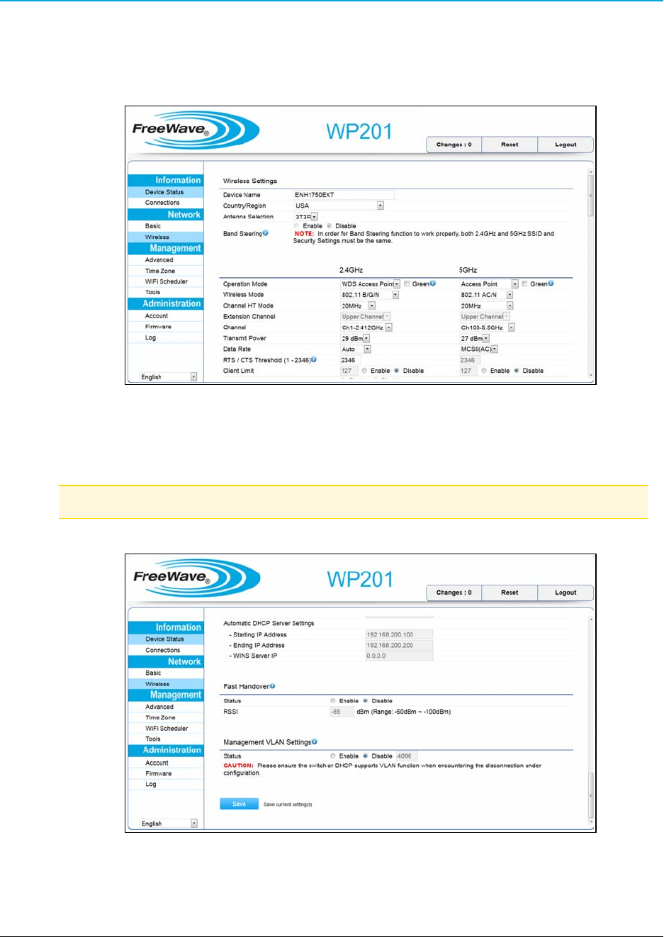
1. In the Access Panel on the left, click Network > Wireless.
The Wireless window opens.
Figure 14: Wireless window
2. Click the Operation Mode list box arrow for the designated frequency and select the
applicable Mode for the WP201.
Note: See Modes for detailed information and examples about the different modes.
3. Scroll to the bottom of the window and click Save.
Figure 15: Wireless window
AProcessing bar appears.
LUM0073AA Rev Aug-2015 Page 23 of 38
This document is the property of FreeWave Technologies, Inc. and contains proprietary information owned by
FreeWave®. This document cannot be reproduced in whole or in part by any means without written permission from
FreeWave Technologies, Inc.
2. WP201 Installation and Setup
The Wireless Settings window refreshes.
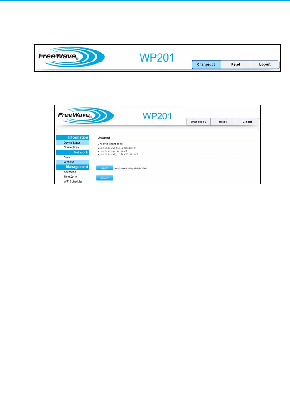
The Changes tab now shows the number of changes to process.
4. Click the Changes tab.
Figure 16: Changes tab showing the number of changes
The Unsaved window opens.
Figure 17: Unsaved window
5. Click Apply to implement all the changes made.
AProcessing bar appears.
The Device Information window reappears when the processing is completed.
6. Optional: In the Access Panel on the left, click Network > Wireless to view the saved
changes.
7. Click Logout to exit the program.
Page 24 of 38 LUM0073AA Rev Aug-2015
This document is the property of FreeWave Technologies, Inc. and contains proprietary information owned by
FreeWave®. This document cannot be reproduced in whole or in part by any means without written permission from
FreeWave Technologies, Inc.
WP201 Access Point: User Manual
2.5 Wall Mounting the WP201
Tools Needed for this Procedure
lDrill
l8mm drill bit
lHammer
lScrewdriver
lPliers
lBox-end wrenches
Procedure
Note: For illustration purposes, the images in this section DO NOT have the antennas or cables
attached to the WP201.
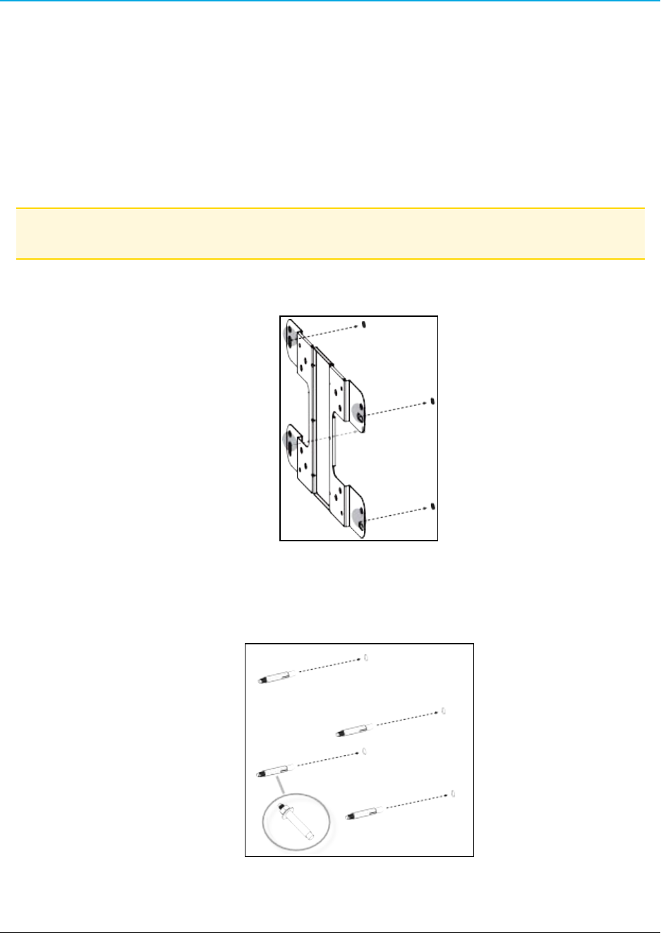
1. Using the Mounting Bracket as a template, mark the locations of the mounting holes on
the wall.
Figure 18: Marked locations of the mounting holes.
2. Drill a 37mm deep, 8mm diameter hole in each of the markings on the wall.
3. Using the bolts in the Mounting Kit Package, hammer the bolts into the openings.
Figure 19: Hammer the bolts into the drilled openings.
LUM0073AA Rev Aug-2015 Page 25 of 38
This document is the property of FreeWave Technologies, Inc. and contains proprietary information owned by
FreeWave®. This document cannot be reproduced in whole or in part by any means without written permission from
FreeWave Technologies, Inc.
2. WP201 Installation and Setup
4. Verify all antennas are attached to their correct ports and the Ethernet cable is connected
between the PoE Injector and the WP201.
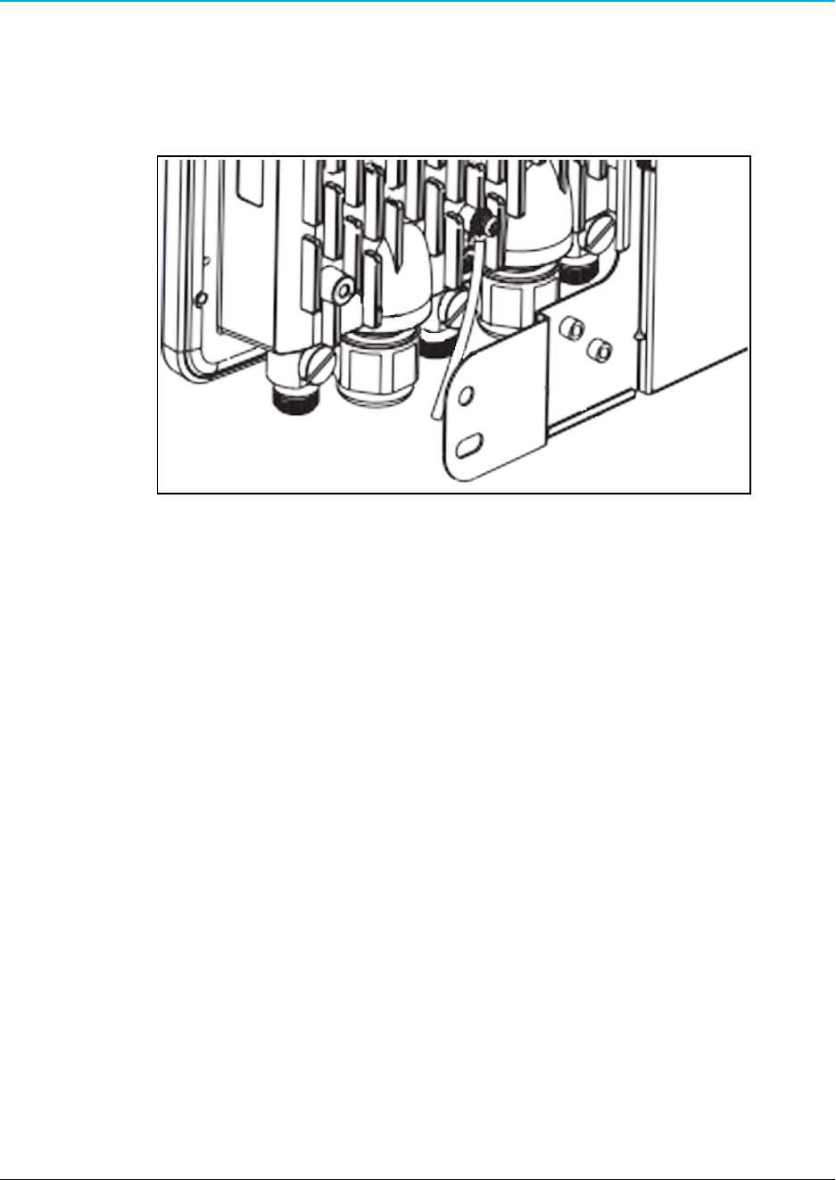
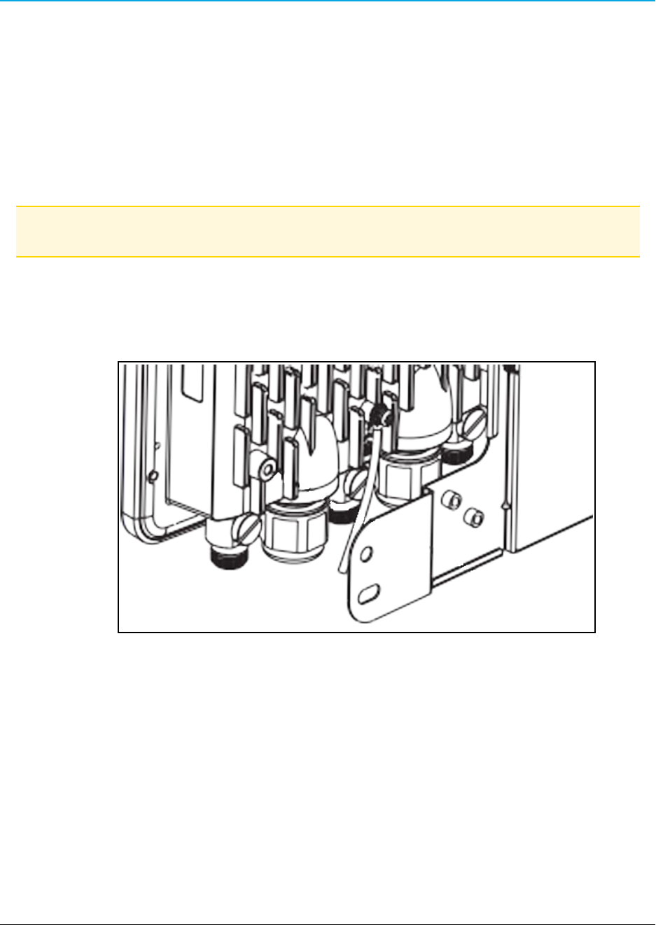
5. Using the enclosed Packaged Ground Screw, attach the loop end of one of the supplied
Green Ground Cables to the ground point on the Back of the WP201 (on page 14).
Figure 20: Attached Ground Cable
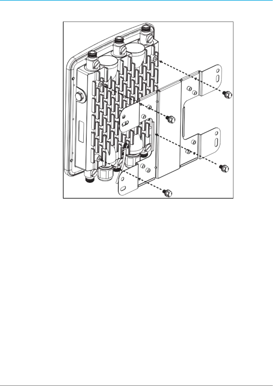
6. Place the lock and flat washers on the four hex cap screws.
Page 26 of 38 LUM0073AA Rev Aug-2015
This document is the property of FreeWave Technologies, Inc. and contains proprietary information owned by
FreeWave®. This document cannot be reproduced in whole or in part by any means without written permission from
FreeWave Technologies, Inc.
WP201 Access Point: User Manual
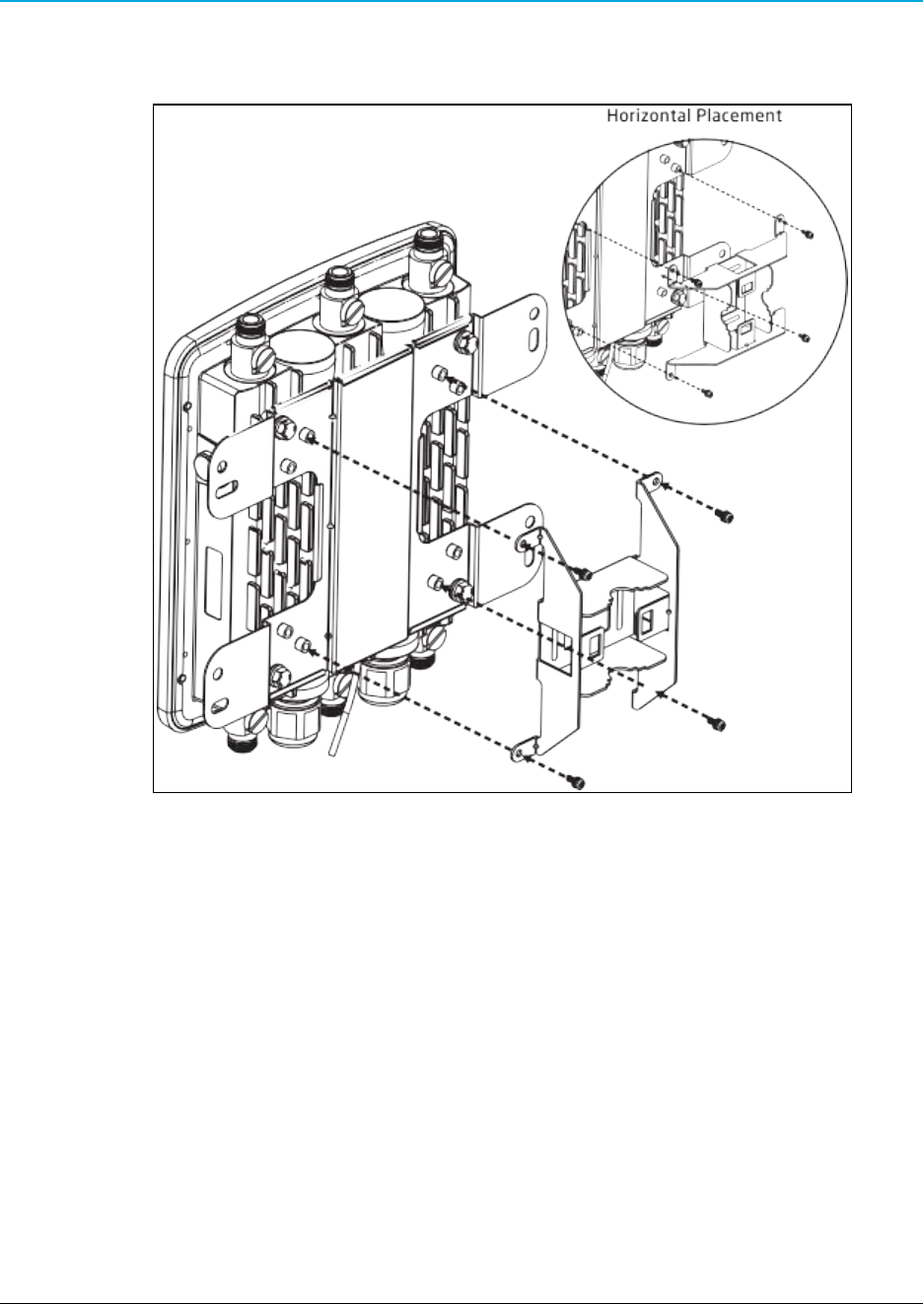
7. Insert and tighten the screws to attach the bracket to the Back of the WP201 (on page 14).
Figure 21: Insert and tighten the screws to attach the bracket.
LUM0073AA Rev Aug-2015 Page 27 of 38
This document is the property of FreeWave Technologies, Inc. and contains proprietary information owned by
FreeWave®. This document cannot be reproduced in whole or in part by any means without written permission from
FreeWave Technologies, Inc.
2. WP201 Installation and Setup
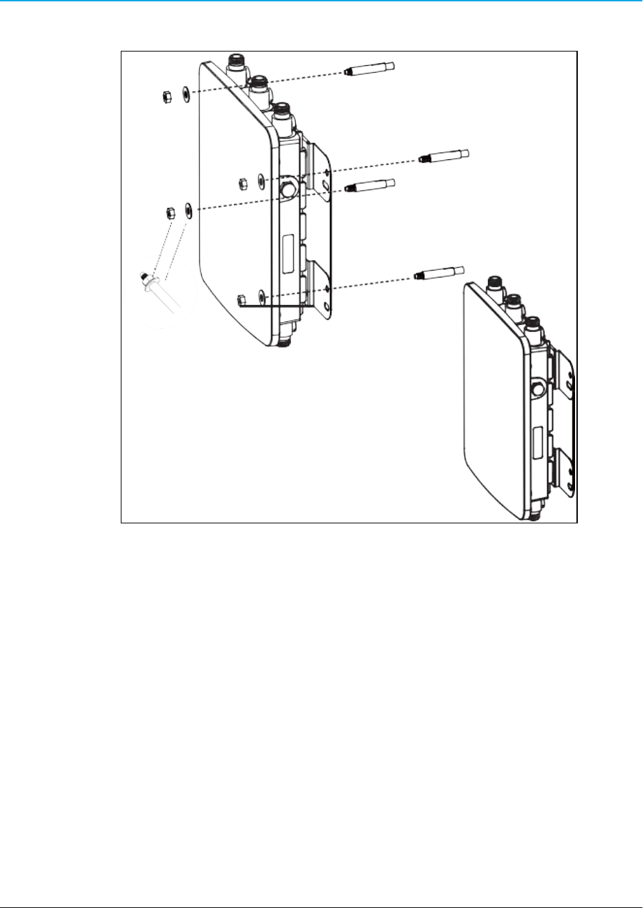
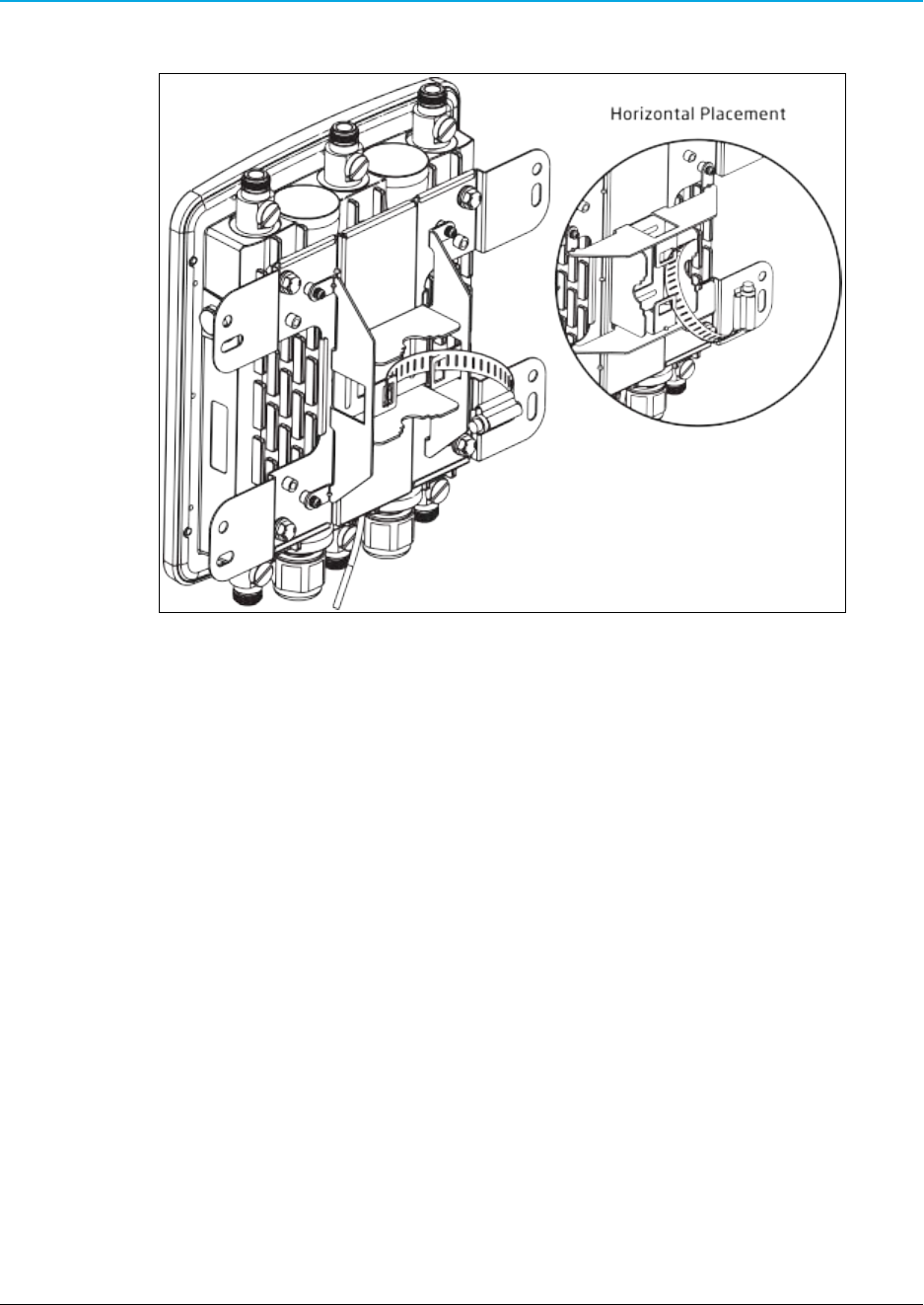
8. Tighten the nut and flat washers to secure the bracket to the mounting surface.
Figure 22: Tighten the nut and flat washers to secure the bracket.
9. Attach the wire end of the Green Ground Cable to a grounding rod (the loop end was
attached to the WP201 in a previous step).
Page 28 of 38 LUM0073AA Rev Aug-2015
This document is the property of FreeWave Technologies, Inc. and contains proprietary information owned by
FreeWave®. This document cannot be reproduced in whole or in part by any means without written permission from
FreeWave Technologies, Inc.
WP201 Access Point: User Manual
2.6 Pole Mounting the WP201
Tools Needed for this Procedure
lDrill
l8mm drill bit
lHammer
lScrewdriver
lPliers
lBox-end wrenches
Procedure
Note: For illustration purposes, the images in this section DO NOT have the antennas or cables
attached to the WP201.
1. Verify all antennas are attached to their correct ports and the Ethernet cable is connected
between the PoE Injector and the WP201.
2. Using the enclosed Packaged Ground Screw, attach the loop end of one of the supplied
Green Ground Cables to the ground point on the Back of the WP201 (on page 14).
Figure 23: Attached Ground Cable
3. Place the lock and flat washers on the four hex cap screws.
LUM0073AA Rev Aug-2015 Page 29 of 38
This document is the property of FreeWave Technologies, Inc. and contains proprietary information owned by
FreeWave®. This document cannot be reproduced in whole or in part by any means without written permission from
FreeWave Technologies, Inc.

2. WP201 Installation and Setup
4. Insert and tighten the screws to attach the bracket to the Back of the WP201 (on page 14).
Figure 24: Insert and tighten the screws to attach the bracket.
Page 30 of 38 LUM0073AA Rev Aug-2015
This document is the property of FreeWave Technologies, Inc. and contains proprietary information owned by
FreeWave®. This document cannot be reproduced in whole or in part by any means without written permission from
FreeWave Technologies, Inc.
WP201 Access Point: User Manual
5. Insert and tighten the four round head screws to attach the Pole Mount Bracket to the
bracket.
Figure 25: Insert and tighten the four round head screws.
LUM0073AA Rev Aug-2015 Page 31 of 38
This document is the property of FreeWave Technologies, Inc. and contains proprietary information owned by
FreeWave®. This document cannot be reproduced in whole or in part by any means without written permission from
FreeWave Technologies, Inc.
2. WP201 Installation and Setup
6. Thread the open end of the Pole Strap through the two tabs on the Pole Mount Bracket.
Figure 26: Thread the open end of the Pole Strap.
Page 32 of 38 LUM0073AA Rev Aug-2015
This document is the property of FreeWave Technologies, Inc. and contains proprietary information owned by
FreeWave®. This document cannot be reproduced in whole or in part by any means without written permission from
FreeWave Technologies, Inc.
WP201 Access Point: User Manual
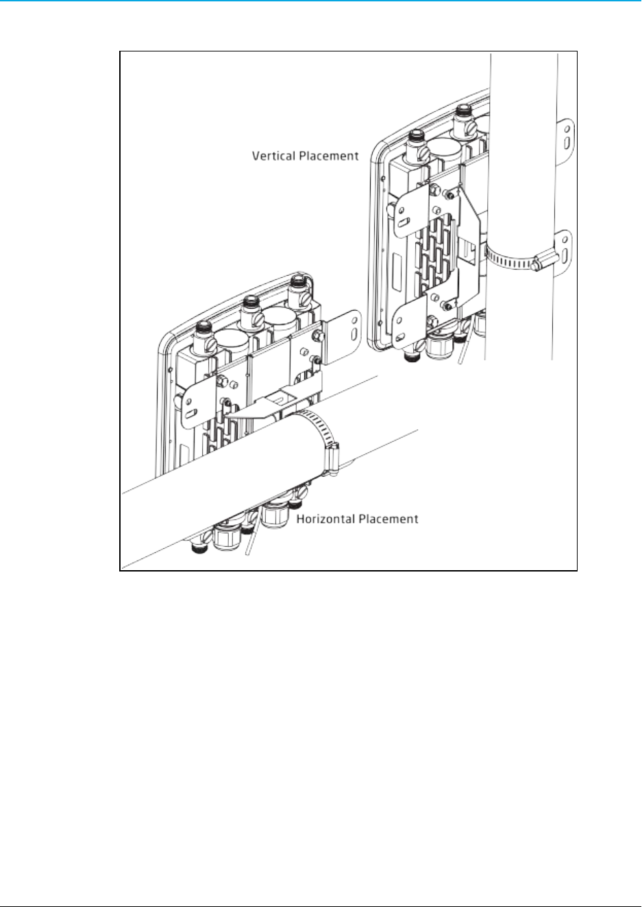
7. Lock and tighten the Pole Strap to secure the Pole Mount Bracket to the pole.
Figure 27: Lock and tighten the Pole Strap.
8. Attach the wire end of the Green Ground Cable to a grounding rod (the loop end was
attached to the WP201 in a previous step).
LUM0073AA Rev Aug-2015 Page 33 of 38
This document is the property of FreeWave Technologies, Inc. and contains proprietary information owned by
FreeWave®. This document cannot be reproduced in whole or in part by any means without written permission from
FreeWave Technologies, Inc.

Page 34 of 38 LUM0073AA Rev Aug-2015
This document is the property of FreeWave Technologies, Inc. and contains proprietary information owned by
FreeWave®. This document cannot be reproduced in whole or in part by any means without written permission from
FreeWave Technologies, Inc.

WP201 Access Point: User Manual
Appendix A: WP201 Technical Specifications
Specifications may change at any time without notice. For the most up-to-date specifications
information, see the product's data sheet available at www.freewave.com.
WP201 Technical Specifications
Specification Description
Wireless Interfaces
Network Configurations lPTP
lPtMP
lFixed Point Mesh
lMobile Mesh
RF Frequency Support 2.41 to 2.47 GHz (ITU ISM band)
5.15 to 5.825 GHz (U-NII & ISM bands)
RF Modulation Technology OFDM: BPSK, QPSK, 16-QAM, 64-QAM
With Adaptive Link
Over the Air Security WPA, WPA2, WPA-Enterprise,
AES - 128, 802.11i
Error Correction FEC, ARQ
SSID Multiple
RF Interface 6 N-type Connectors
Antennas 6 External N-type Antennas
l3 x detachable 5 dBi 2.4 GHz omni-directional antennas
l3 x detachable 7 dBi 5 GHz omni-directional antennas
LUM0073AARev Aug-2015 Page 35 of 38
This document is the property of FreeWave Technologies, Inc. and contains proprietary information owned by
FreeWave®. This document cannot be reproduced in whole or in part by any means without written permission from
FreeWave Technologies, Inc.

Appendix A: WP201 Technical Specifications
WP201 Technical Specifications
Specification Description
Wired Interfaces
Network Interface 2 - 10/100/1000 Gigabit Ethernet port with PoE support
2 LAN Ports:
l1 - LAN 1 Port - PoE Input
l1 - LAN 2 Port - PSE Output
LAN / WAN 802.3 and 802.3u, IPv4, TCP, UDP, ICMP
DHCP Server and Client, NAT
VLAN lVLAN Pass-through
lVLAN Tag
LAN Security RADIUS, X.509 Certificates,
MAC Filtering with ACL
IPsec, AES-128, AES-256, SSH, SSH-2
Management lAuto Channel Selection
lBand Steering
lBSSID
lClients Statistics
lE-Mail Alert
lFast Roaming
lFast Handover
lGuest Network
lMIB:
lMIB I
lMIB II
lPrivate MIB
lMultiple SSID:
l16 SSIDs, 8 SSIDs per Radio
lRADIUS Accounting
lSave Configuration as User Default
lSNMP V1/V2c/V3
QoS 802.1e
Power
Power Requirements lExternal Power Adapter on PoE Injector (EPE-48GR), DC IN 48
V/0.8A
lPower Supply***:
l90 to 240 VDC ± 10%, 50/60 Hz
l***depends on different countries
Page 36 of 38 LUM0073AA Rev Aug-2015
This document is the property of FreeWave Technologies, Inc. and contains proprietary information owned by
FreeWave®. This document cannot be reproduced in whole or in part by any means without written permission from
FreeWave Technologies, Inc.

WP201 Access Point: User Manual
LUM0073AA Rev Aug-2015 Page 37 of 38
This document is the property of FreeWave Technologies, Inc. and contains proprietary information owned by
FreeWave®. This document cannot be reproduced in whole or in part by any means without written permission from
FreeWave Technologies, Inc.