FreeWave Technologies PRW5000AA Wireless 802.11ac/b/g/n access point User Manual My
FreeWave Technologies Inc. Wireless 802.11ac/b/g/n access point My
UserManual.wiki
>
FreeWave Technologies
>
PRW5000AA User Manual
>
User Manual
Contents
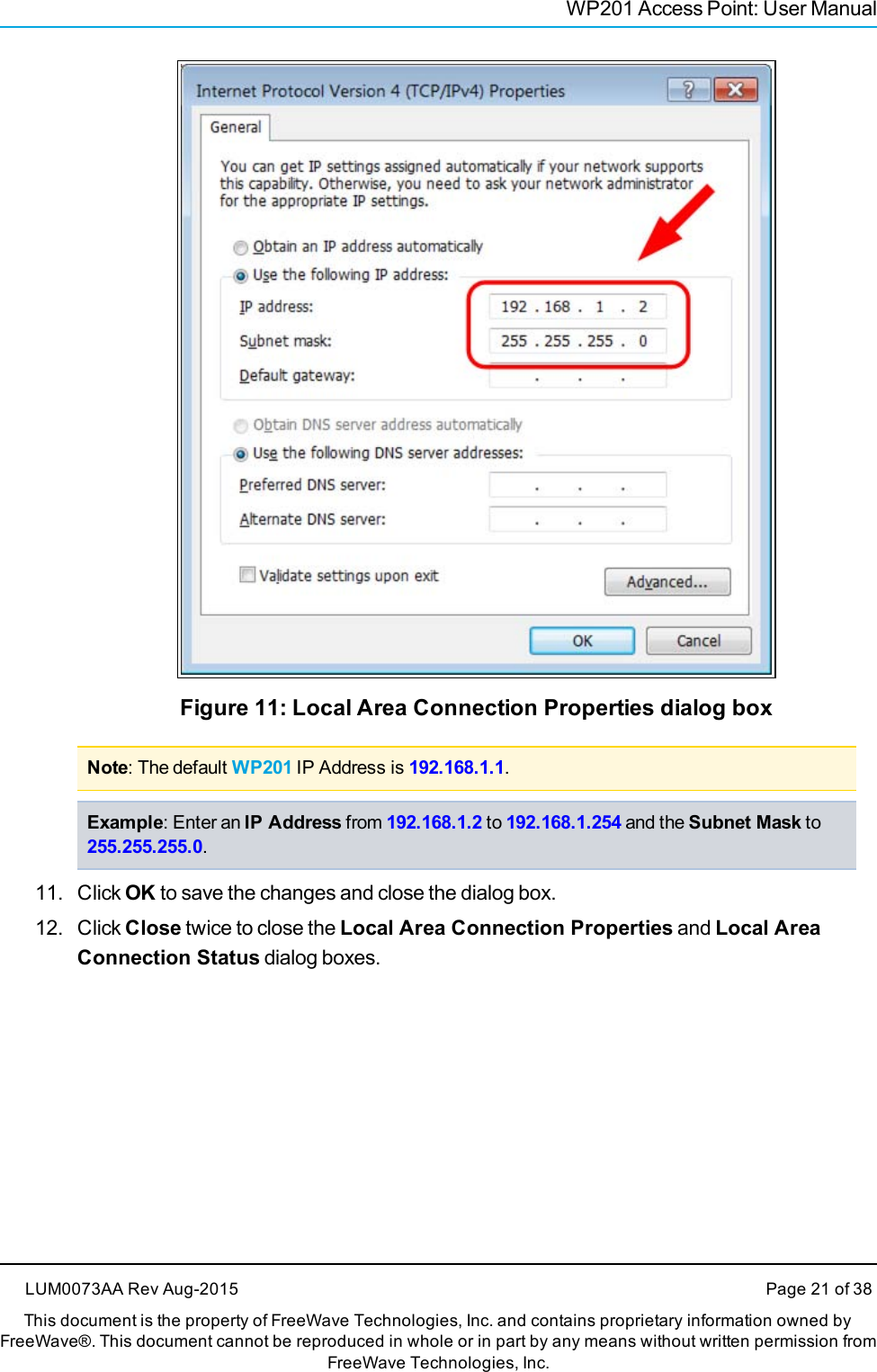
1.
User Manual
2.
User Manual User Notifications
User Manual
Navigation menu
Upload a User Manual
Namespaces
Wiki Guide
HTML
PDF
Info
Views
User Manual
Discussion / Help
Navigation
![PrefacelFreeWave applications appear as: FreeWave.lParameter setting text appears as: [Page=radioSettings]lFile names appear as: configuration.cfg.lFile paths appear as: C:\Program Files (x86)\FreeWave Technologies.lUser-entered text appears as: xxxxxxxxx.l3rd-party names appear as: Notepad®.Caution: Indicates a situation that MAY cause damage to personnel, the radio, data, ornetwork.Example: Provides example information of the related text.FreeWave Recommends: Identifies FreeWave recommendation information.Important!: Provides semi-cautionary information relevant to the text or procedure.Note: Emphasis of specific information relevant to the text or procedure.Provides time saving or informative suggestions about using the product.Warning! Indicates a situation that WILL cause damage to personnel, the radio, data, ornetwork.Documentation FeedbackSend comments or questions about this document's content to techpubs@freewave.com. In theemail, include the title of the document or the document's part number and revision letter (found inthe footer).Page 8 of 38 LUM0073AA Rev Aug-2015This document is the property of FreeWave Technologies, Inc. and contains proprietary information owned byFreeWave®. This document cannot be reproduced in whole or in part by any means without written permission fromFreeWave Technologies, Inc.](https://usermanual.wiki/FreeWave-Technologies/PRW5000AA.User-Manual/User-Guide-2782930-Page-8.png)