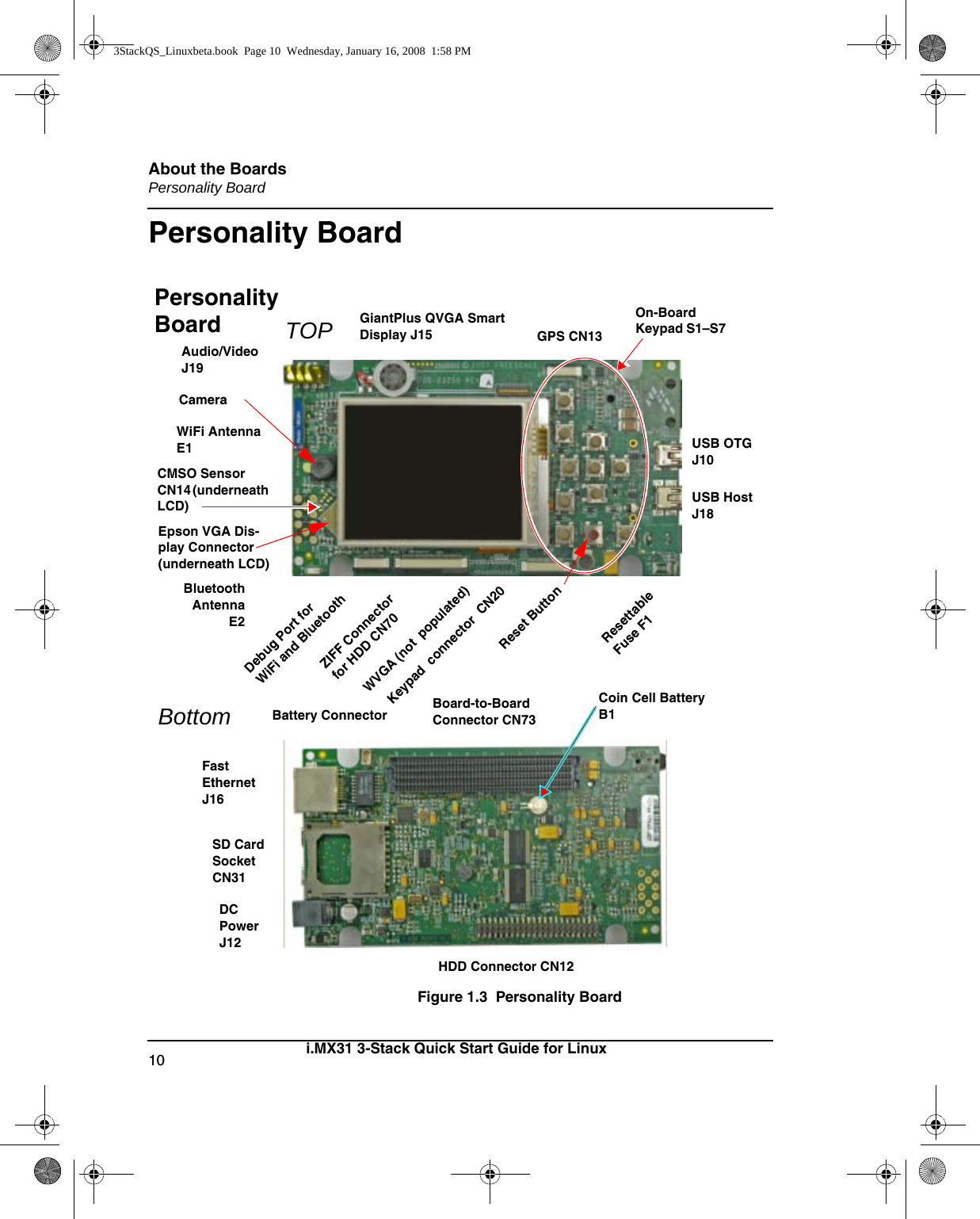
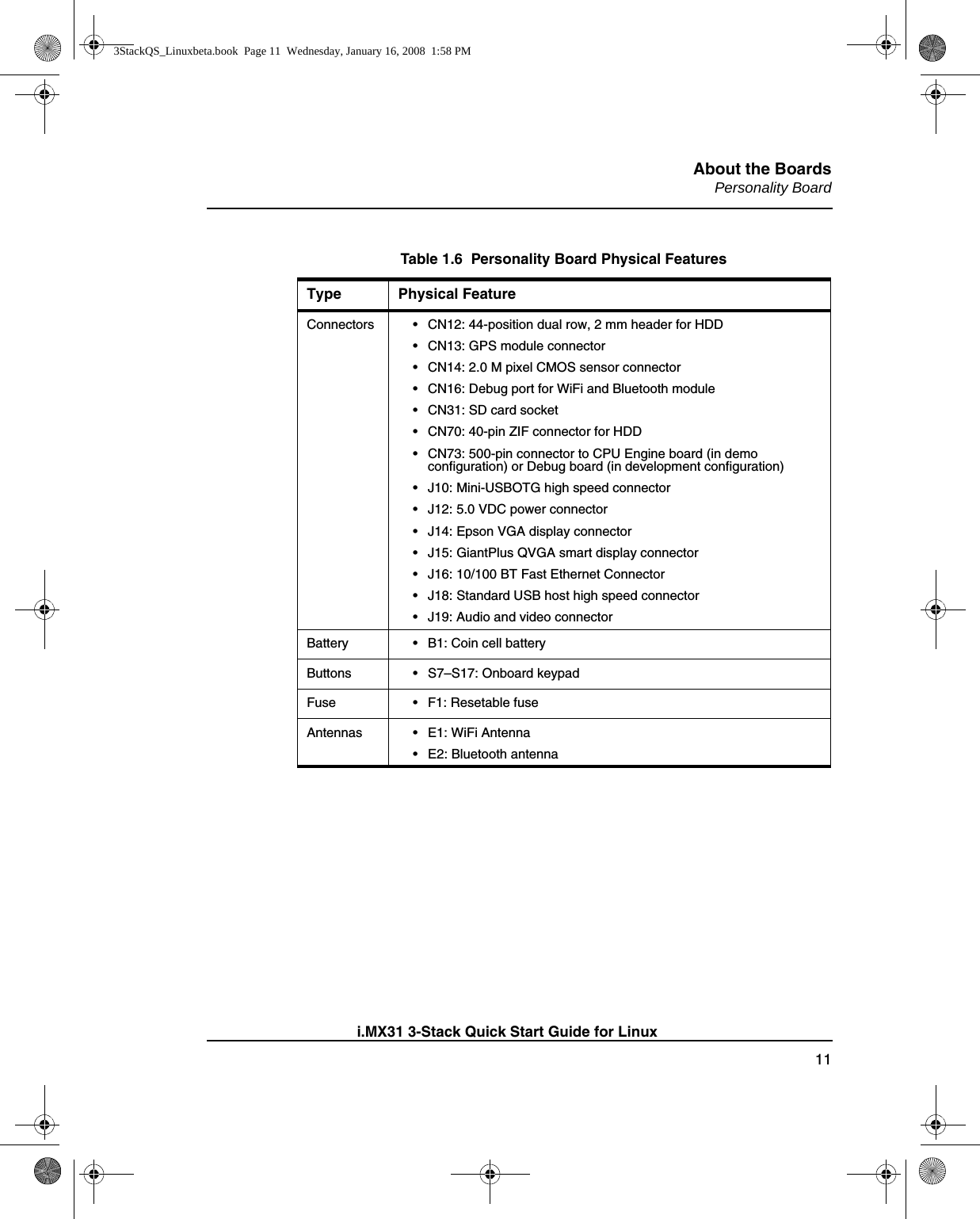
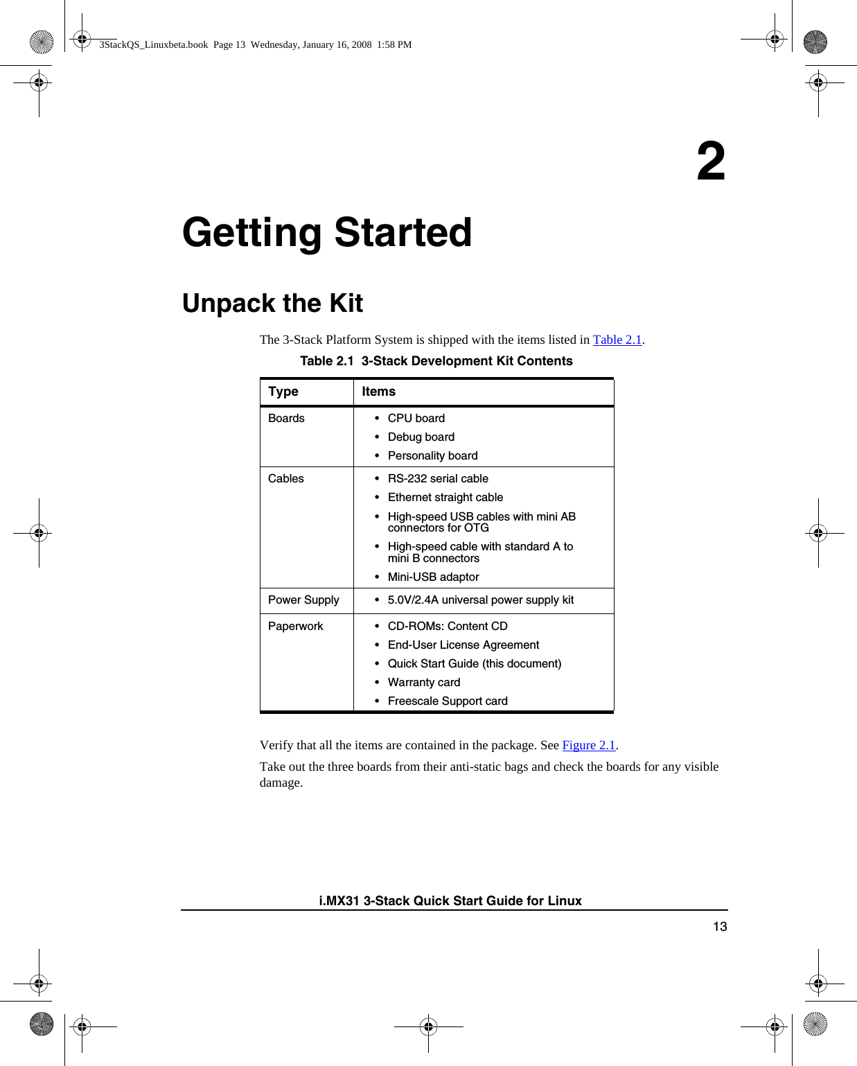
Freescale Semiconductor MCIMX31PDK iMX31 - 3 Stack Development Kit User Manual 3StackQS Linuxbeta

Freescale Semiconductor, Inc. iMX31 - 3 Stack Development Kit 3StackQS Linuxbeta

User Manual

i.MX31 3-Stack Development KitQuick Start Guidefor Linux  3StackQS_Linuxbeta.book  Page 1  Wednesday, January 16, 2008  1:58 PM
Information in this document is provided solely to enable system and software implementers to use Freescale Semicon-ductor products. There are no express or implied copyright licenses granted hereunder to design or fabricate any inte-grated circuits or integrated circuits based on the information in this document.Freescale Semiconductor reserves the right to make changes without further notice to any products herein. FreescaleSemiconductor makes no warranty, representation or guarantee regarding the suitability of its products for any partic-ular purpose, nor does Freescale Semiconductor assume any liability arising out of the application or use of any productor circuit, and specifically disclaims any and all liability, including without limitation consequential or incidental dam-ages. “Typical” parameters that may be provided in Freescale Semiconductor data sheets and/or specifications can anddo vary in different applications and actual performance may vary over time. All operating parameters, including “Typ-icals”, must be validated for each customer application by customer’s technical experts. Freescale Semiconductor doesnot convey any license under its patent rights nor the rights of others. Freescale Semiconductor products are not de-signed, intended, or authorized for use as components in systems intended for surgical implant into the body, or otherapplications intended to support or sustain life, or for any other application in which the failure of the Freescale Semi-conductor product could create a situation where personal injury or death may occur. Should Buyer purchase or useFreescale Semiconductor products for any such unintended or unauthorized application, Buyer shall indemnify and holdFreescale Semiconductor and its officers, employees, subsidiaries, affiliates, and distributors harmless against allclaims, costs, damages, and expenses, and reasonable attorney fees arising out of, directly or indirectly, any claim ofpersonal injury or death associated with such unintended or unauthorized use, even if such claim alleges that FreescaleSemiconductor was negligent regarding the design or manufacture of the part.Federal Communications Commission Radio Frequency Interference StatementThis device complies with Part 15 of the FCC rules. Operation is subject to the following two conditions:(1) This device may not cause harmful interference and(2) this device must accept any interference received, including interference that might cause undesired operation.Changes or modifications to this equipment not expressly approved by Freescale could void the user’s authority tooperate the equipment. 3StackQS_Linuxbeta.book  Page 2  Wednesday, January 16, 2008  1:58 PMThis equipment has been tested and found to comply with the limits for a Class B digital device, pursuant to part 15 of the FCC Rules. These limits are designed to provide reasonable protection against harmful interference in a residential installation. This equipment generates uses and can radiate radio frequency energy and, if not installed and used in accordance with the instructions, may cause harmful interference to radio communications. However, there is no guarantee that interference will not occur in a particular installation. If this equipment does cause harmful interference to radio or television reception, which can be determined by turning the equipment off and on, the user is encouraged to try to correct the interference by one or more of the following measures: —Reorient or relocate the receiving antenna. —Increase the separation between the equipment and receiver. —Connect the equipment into an outlet on a circuit different from that to which the receiver is connected. —Consult the dealer or an experienced radio/TV technician for help. SAR Precautions The radiated output power of this device is below the FCC radio frequency exposure limits based on that human proximity to the antennas shall not be less than 1.6cm during normal operation.
 Freescale™ and the Freescale logo are trademarks of Freescale Semiconductor, Inc. All other product or service namesare the property of their respective owners. © Freescale Semiconductor, Inc. 2007. All rights reserved.How to Reach Us:Home Page:www.freescale.comE-mail:support@freescale.comUSA/Europe or Locations Not Listed:Freescale SemiconductorTechnical Information Center, CH3701300 N. Alma School RoadChandler, Arizona 85224+1-800-521-6274 or +1-480-768-2130support@freescale.comEurope, Middle East, and Africa:Freescale Halbleiter Deutschland GmbHTechnical Information CenterSchatzbogen 781829 Muenchen, Germany+44 1296 380 456 (English)+46 8 52200080 (English)+49 89 92103 559 (German)+33 1 69 35 48 48 (French)support@freescale.comJapan:Freescale Semiconductor Japan Ltd.HeadquartersARCO Tower 15F1-8-1, Shimo-Meguro, Meguro-ku,Tokyo 153-0064, Japan0120 191014 or +81 3 5437 9125support.japan@freescale.comAsia/Pacific:Freescale Semiconductor Hong Kong Ltd.Technical Information Center2 Dai King StreetTai Po Industrial EstateTai Po, N.T., Hong Kong+800 2666 8080support.asia@freescale.comFor Literature Requests Only:Freescale Semiconductor Literature Distribution CenterP.O. Box 5405Denver, Colorado 802171-800-521-6274 or 303-675-2140Fax: 303-675-2150LDCForFreescaleSemiconductor@hibbertgroup.com
1i.MX31 3-Stack Quick Start Guide for Linux1 About the Boards 3About the 3-Stack Platform System . . . . . . . . . . . . . . . . . . . . . . . . . . . . . . . . . . . 3CPU Board . . . . . . . . . . . . . . . . . . . . . . . . . . . . . . . . . . . . . . . . . . . . . . . . . . . . . . 6Debug Board. . . . . . . . . . . . . . . . . . . . . . . . . . . . . . . . . . . . . . . . . . . . . . . . . . . . . 8Personality Board . . . . . . . . . . . . . . . . . . . . . . . . . . . . . . . . . . . . . . . . . . . . . . . . 112 Getting Started 13Unpack the Kit . . . . . . . . . . . . . . . . . . . . . . . . . . . . . . . . . . . . . . . . . . . . . . . . . . 13CD-ROM Contents . . . . . . . . . . . . . . . . . . . . . . . . . . . . . . . . . . . . . . . . . . . . . . . 15Provide a Development PC. . . . . . . . . . . . . . . . . . . . . . . . . . . . . . . . . . . . . . . . . 163 Build the Platform 17Build a Development Platform: Assemble 3 Boards . . . . . . . . . . . . . . . . . . . . . 17Connect Personality Board to Debug Board . . . . . . . . . . . . . . . . . . . . . . . . . 18Connect CPU Board to Debug Board . . . . . . . . . . . . . . . . . . . . . . . . . . . . . . 19Connect Development Platform to PC; Run Preloaded Image . . . . . . . . . . . 20Build a Demo Platform: Assemble 2 Boards . . . . . . . . . . . . . . . . . . . . . . . . . . . 21Connect CPU Board to Personality Board . . . . . . . . . . . . . . . . . . . . . . . . . . 22Connect Power Supply; Run Preloaded Demo . . . . . . . . . . . . . . . . . . . . . . . 234 Using the Linux Demo Image 25Linux Menus. . . . . . . . . . . . . . . . . . . . . . . . . . . . . . . . . . . . . . . . . . . . . . . . . . . . 25Multimedia Applications Menu  . . . . . . . . . . . . . . . . . . . . . . . . . . . . . . . . . . 25Connectivity Menu . . . . . . . . . . . . . . . . . . . . . . . . . . . . . . . . . . . . . . . . . . . .25Settings Menu . . . . . . . . . . . . . . . . . . . . . . . . . . . . . . . . . . . . . . . . . . . . . . . . 25Downloading Multimedia to the 3-Stack Board . . . . . . . . . . . . . . . . . . . . . . . . . 26Using an SD Card . . . . . . . . . . . . . . . . . . . . . . . . . . . . . . . . . . . . . . . . . . . . . 27Using a USB Mass Storage Application . . . . . . . . . . . . . . . . . . . . . . . . . . . . 293StackQS_Linuxbeta.book  Page 1  Wednesday, January 16, 2008  1:58 PM
2i.MX31 3-Stack Quick Start Guide for LinuxRunning the Video, Audio, and Picture Applications . . . . . . . . . . . . . . . . . . . . .29Running the Video Application . . . . . . . . . . . . . . . . . . . . . . . . . . . . . . . . . . .29Running the Audio Application. . . . . . . . . . . . . . . . . . . . . . . . . . . . . . . . . . .30Running the Picture Viewer Application. . . . . . . . . . . . . . . . . . . . . . . . . . . .30Running the Camera Application  . . . . . . . . . . . . . . . . . . . . . . . . . . . . . . . . .31Running the FM Radio Application  . . . . . . . . . . . . . . . . . . . . . . . . . . . . . . .31Supported Codecs . . . . . . . . . . . . . . . . . . . . . . . . . . . . . . . . . . . . . . . . . . . . .32Ready to Begin Your Development?. . . . . . . . . . . . . . . . . . . . . . . . . . . . . . . . . .333StackQS_Linuxbeta.book  Page 2  Wednesday, January 16, 2008  1:58 PM
3i.MX31 3-Stack Quick Start Guide for Linux1About the BoardsThis chapter provides detailed information about the three boards (CPU, Debug, Personality) and identifies the locations of the connectors and switches. About the 3-Stack Platform SystemFreescale introduces the 3-Stack Platform System, which you use to develop multimedia and connectivity applications using the i.M31 Applications Processor and the MC13783 Audio and Power Management device. The 3-Stack Platform System decreases the time between first development and final product release by providing you (as the system designer) with a near-to-final product design, which you can use as a development platform for software and hardware.There are two Board Support Packages (BSP) for the 3-Stack Platform System, with one BSP for WinCE and one BSP for Linux operating systems. These BSPs contain drivers optimized for multimedia operations using the i.MX31 and MC13783 devices.Freescale's 3-Stack Platform System consists of three small boards: CPU, Debug, and Personality. • A CPU board contains the i.MX31 CPU, memories and the MC13783 Power Management IC (PMIC). • A Debug board provides the debug interfaces (like JTAG), and also has a CPLD that implements an external Ethernet and serial controller for debug purposes. • The Personality board implements the functionality of the 3-Stack board system, and contains hardware for WiFi connectivity, FM receiver, and so on. The Personality board can be modified to meet your specific requirements without the need to modify the other two boards (CPU, Debug). The Personality board was designed to support common multimedia applications, and has a 2.8-inch VGA display, image sensor Table 1.1  Chapter SummaryBoard See3-Stack Platform “About the 3-Stack Platform System” on page 3CPU “CPU Board” on page 6Debug “Debug Board” on page 7Personality “Personality Board” on page 103StackQS_Linuxbeta.book  Page 3  Wednesday, January 16, 2008  1:58 PM
About the BoardsAbout the 3-Stack Platform System4i.MX31 3-Stack Quick Start Guide for Linuxcamera, WiFi 802.11g/b, FM receiver, SD Card connector, USB OTG, USB Host, 2.4 QVGA smart display panel connector, ATA connector and TV-Out connector. As the 3-Stack Platform continues to evolve, more Personality boards will be created to meet new multimedia requirements.Table 1.2 describes the 3-Stack Platform features in detail. Table 1.2  3-Stack Platform FeaturesItem DescriptionAll boards • Near to final product form-factor demonstration modules and working platforms.• Solid reference schematics that closely resemble final products to aid customers' designs.CPU board • i.MX31 ARM-11 Applications Processor• MC13783 Atlas power management chip• 256 MB of NAND Flash Memory• 128 MB of 32 bit DDR SDRAM memory• 37.914 mm x 67.517 mmPersonality board • Peripheral components • Interface connectors• 71.428 mm x 129.462 mmDebug board • Two RS-232 interfaces• 10/100 Base-T Ethernet connector• Current measure connectors• 71.400 mm x 174.900 mmExpansion Headers • Utilizing reliable high density connector to interface between boards, 3 board assembly for software development and 2-board assembly (without debug board) for demonstrationBattery Support • +4.2 V 2400mAh Battery power supply and Battery Charging Function LCD Display • 2.8 inch TFTLCD display panel with touch panel and LED backlightSmart LCD Connector • 2.4 inch QVGA smart display panel connectorCamera Interface • Image sensor camera connectorSelectable Clock Sources• Two selectable system clock sources: 32.768 KHz and 26 MhzDebug Port • RealView-ICE debug support3StackQS_Linuxbeta.book  Page 4  Wednesday, January 16, 2008  1:58 PM
About the BoardsAbout the 3-Stack Platform System5i.MX31 3-Stack Quick Start Guide for LinuxVideo and Audio Stereo• Stereo microphone jack, headphone and video jack, stereo and mono (ear piece) speaker terminalsGPS Connector • One connector to outboard GPS moduleFM ReceiverTV Out • TV decoder that supports 8-bit color, NTSC and PAL formatsPC Card Expansion • SD card connectors, with card sense Keypad • Onboard keypad and keypad connectorNetwork Support • WiFi 802.11g/b and BT2.0 + EDR Combo Module onboard• One Ethernet jack connector (for application/debug)USB • One USB OTG high-speed transceiver with mini-USB connector• One USB high-speed host transceiver, with standard USB host connectorATA Support ATA5 controller with • One 44-position dual row 2 mm header for small form-factor disk drivers • One 40-pin ZIF connector for Toshiba HDDAccelerometer • Onboard accelerometer with sensitivity in three separate axes (X, Y, Z)Serial Port Two RS-232 interfaces with DB-9 connectors• One RS-232 interface is driven by a UART channel internal to the MX31, and it supports DCE with optional full modem controls• The other RS-232 interface is DTE with optional full modem controlsCables • 5.0V/2.4A universal power supply kit• RS-232 standard serial cable• High Speed USB cables with mini-AB connectors for OTG• High speed cable with standard A-to-mini-B connectors• Mini-USB adaptor• Ethernet cables (2) with RJ45-8 connectorsTable 1.2  3-Stack Platform FeaturesItem Description3StackQS_Linuxbeta.book  Page 5  Wednesday, January 16, 2008  1:58 PM
About the BoardsCPU Board6i.MX31 3-Stack Quick Start Guide for LinuxCPU BoardFigure 1.1  CPU BoardYou use the J1 board-to-board connector (500 pins) to connect the CPU board to either of the other two boards:• Connect the CPU board to a Personality board, for running demos (no Debug board is needed). • Connect the CPU board to a Debug board, (and connect the Personality board to the Debug board) for developing software. The Personality board plugs into the other side of the Debug board.Software • Sample Windows® embedded CE binary image from Freescale• Windows embedded CE BSP available from FreescaleApplication Development Tools• ATK software• Platform Builder 5.0/6.0• Visual Studio 2005Table 1.2  3-Stack Platform FeaturesItem DescriptionJ1 Board-to-Board ConnectorCPU Board TopBottom3StackQS_Linuxbeta.book  Page 6  Wednesday, January 16, 2008  1:58 PM
About the BoardsDebug Board7i.MX31 3-Stack Quick Start Guide for LinuxDebug BoardFigure 1.2  Debug BoardTo Personality Board Connector CN74Current Measure J3MX31 JTAG CN1SW5–SW10 See Table 1.53.3V LED D9Power-On S4DC Power LED D11DC Power J2Ethernet J1UART CON4 femaleUART CON3 maleDebug CPLDJTAG CN2PersonalityCPLD JTAGCN3CPLD TestDebug Reset S2CPLD TestPower S1System ResetCPLD LEDs D1–D8SW4 See Table 1.4Debug Board TOPBottomP1P2Resettable Fuse F1To CPU Board Connector3StackQS_Linuxbeta.book  Page 7  Wednesday, January 16, 2008  1:58 PM
About the BoardsDebug Board8i.MX31 3-Stack Quick Start Guide for LinuxTable 1.3  Debug Board Physical FeaturesType Physical FeatureSwitches • S1: Power button• S2: Debug board reset button• S3: System reset switch• S4: Power-on switch• SW4: Enable switchConnectors • J1:10/100 Base-T Ethernet RJ45 connector• J2: 5.0V DC power connector• J3: Current measure connector• J4: 500-pin connector to CPU board• P1: WEIM Address measure connector• P2: WEIM Data measure connector• CN1: i.MX31 JTAG connector• CN2: Debug board CPLD JTAG connector• CN3: Personality board CPLD JTAG connector (Reserved) • CN74: 500-pin connector to Personality board• CON4: UART (DCE) DB9 female connectorLEDs • D1–D8: LEDs for CPLD debug• D9: LED for debug board 3.3V power• D11:LED for DC power supplyButtons • BT1, BT2: Test buttons for CPLDFuse • F1: Resettable Fuse3StackQS_Linuxbeta.book  Page 8  Wednesday, January 16, 2008  1:58 PM
About the BoardsDebug Board9i.MX31 3-Stack Quick Start Guide for LinuxTable 1.4  Debug Board SW4 SwitchSwitch Setting EffectSW4-1 UART Port Select ON Selects serial port UART (DCE) CON4SW4-8 Power Enable ON Power is supplied to all three boards.OFF Power is only supplied to the Debug board.Table 1.5  Boot Mode Setting (SW5–SW10)Boot Mode DeviceSW5 Boot4SW6Boot3SW7SW8 SW9 SW10UART/USB bootloaderX0 0 0 0 08-bit NAND Flash (2KB page) ExtX1 0 0 0 03StackQS_Linuxbeta.book  Page 9  Wednesday, January 16, 2008  1:58 PM
About the BoardsPersonality Board10 i.MX31 3-Stack Quick Start Guide for LinuxPersonality BoardFigure 1.3  Personality Board BluetoothAntennaE2Audio/Video J19USB OTG J10USB Host J18WiFi Antenna E1GPS CN13GiantPlus QVGA Smart Display J15CMSO Sensor CN14 (underneath LCD)Debug Port for WiFi and Bluetooth ZIFF Connector for HDD CN70WVGA (not  populated)Keypad  connector  CN20Resettable Fuse F1TOP On-Board Keypad S1–S7Fast Ethernet J16SD Card Socket CN31DC Power J12HDD Connector CN12Board-to-Board Connector CN73Coin Cell Battery B1BottomPersonality Board   CameraEpson VGA Dis-play Connector(underneath LCD)Reset ButtonBattery Connector 3StackQS_Linuxbeta.book  Page 10  Wednesday, January 16, 2008  1:58 PM
About the BoardsPersonality Board11i.MX31 3-Stack Quick Start Guide for LinuxTable 1.6  Personality Board Physical FeaturesType Physical FeatureConnectors • CN12: 44-position dual row, 2 mm header for HDD• CN13: GPS module connector• CN14: 2.0 M pixel CMOS sensor connector• CN16: Debug port for WiFi and Bluetooth module• CN31: SD card socket• CN70: 40-pin ZIF connector for HDD• CN73: 500-pin connector to CPU Engine board (in demo configuration) or Debug board (in development configuration) • J10: Mini-USBOTG high speed connector• J12: 5.0 VDC power connector• J14: Epson VGA display connector• J15: GiantPlus QVGA smart display connector• J16: 10/100 BT Fast Ethernet Connector• J18: Standard USB host high speed connector• J19: Audio and video connectorBattery • B1: Coin cell batteryButtons • S7–S17: Onboard keypadFuse • F1: Resetable fuseAntennas • E1: WiFi Antenna• E2: Bluetooth antenna 3StackQS_Linuxbeta.book  Page 11  Wednesday, January 16, 2008  1:58 PM
About the BoardsPersonality Board12 i.MX31 3-Stack Quick Start Guide for Linux3StackQS_Linuxbeta.book  Page 12  Wednesday, January 16, 2008  1:58 PM
13i.MX31 3-Stack Quick Start Guide for Linux2Getting StartedUnpack the KitThe 3-Stack Platform System is shipped with the items listed in Table 2.1. Verify that all the items are contained in the package. See Figure 2.1.Take out the three boards from their anti-static bags and check the boards for any visible damage.Table 2.1  3-Stack Development Kit ContentsType ItemsBoards • CPU board• Debug board• Personality boardCables • RS-232 serial cable• Ethernet straight cable• High-speed USB cables with mini AB connectors for OTG• High-speed cable with standard A to mini B connectors• Mini-USB adaptorPower Supply • 5.0V/2.4A universal power supply kitPaperwork • CD-ROMs: Content CD• End-User License Agreement• Quick Start Guide (this document)• Warranty card• Freescale Support card3StackQS_Linuxbeta.book  Page 13  Wednesday, January 16, 2008  1:58 PM
Getting StartedUnpack the Kit14i.MX31 3-Stack Quick Start Guide for LinuxFigure 2.1  PDK Kit ContentsRS-232CD-ROM Ethernet StraightMin-AB USB OTGA to Mini B USB CableCPU BoardDebug BoardUniversal Power SupplyPersonality Board3StackQS_Linuxbeta.book  Page 14  Wednesday, January 16, 2008  1:58 PM
Getting StartedCD-ROM Contents15i.MX31 3-Stack Quick Start Guide for LinuxCD-ROM ContentsTable 2.2.identifies the items on the CD-ROM set. Table 2.2  Development PC RequirementsType RequirementProduct Documentation• 3-Stack Platform Product Brief• Bill of Materials, Schematics, and Gerber files for CPU Board, Personality Board, and Debug Board• 3-Stack Platform Hardware User’s Guide• i.MX31 MAX PDK Readme, Linux 2.6.19• i.MX31 MAX PDK Quick Start Guide, Linux 2.6.19• i.MX31 MAX PDK Release Notes,  Linux 2.6.19• i.MX31 MAX PDK User’s Guide, Linux 2.6.19• i.MX31 MAX PDK Reference Manual, Linux 2.6.19• i.MX31 MAX PDK Hello World Application Note, Linux 2.6.19• Data sheets for the 3-Stack Platform’s non-Freescale components• Advanced ToolKit (ATK) User’s GuideSoftware Development Tools• Linux Toolchain (included in LTIB distribution)• Linux SDK installation file• Advanced ToolKit (ATK) software3StackQS_Linuxbeta.book  Page 15  Wednesday, January 16, 2008  1:58 PM
Getting StartedProvide a Development PC16i.MX31 3-Stack Quick Start Guide for LinuxProvide a Development PCTo develop applications using the 3-Stack development kit, you need a PC with the requirements shown in Table 2.3. Table 2.3  Development PC RequirementsType RequirementOperating System Linux OS- the following are platforms on which LTIB was tested.• Redhat: 7.3, 8.0, 9.0• Fedora Core: 1, 2, 3• Debian: 3.1r0 (stable), unstable• SuSE: 8.2, 9.2, 10.0 Network • Internet accessPC HW • 933 MHz Pentium II or later processor; 2 GHz processor recommended• 512 MB of RAM; 1 GB recommended• 1 GB of available space required on system drive• 10 GB of available hard-disk space•DVD ROM drive• 1024x768 or higher resolution display with 256 colors3StackQS_Linuxbeta.book  Page 16  Wednesday, January 16, 2008  1:58 PM
17i.MX31 3-Stack Development Kit Quick Start Guide3Build the PlatformThis chapter explains how to connect the three types of 3-Stack boards (Debug, Personality, CPU) together, to make either a development platform (Personality board + CPU board + Debug board), or a demonstration platform (Personality board + CPU board), and how to connect the 3-Stack platform to your PC. See Figure 3.1. Figure 3.1  3-Stack Platform ConfigurationsThe three 3-Stack boards in your development kit may already be assembled. If the three boards are already assembled, review the procedures in the following sections, and be sure to configure the debug board appropriately.• To build a development platform, follow the procedures in “Build a Development Platform: Assemble 3 Boards” on page 17. • To build a demonstration platform, follow the procedures in “Build a Demo Platform: Assemble 2 Boards” on page 21.Build a Development Platform: Assemble 3 Boards This section explains how to connect the Personality, Debug, and CPU boards.Development ConfigurationPersonality BoardDebug BoardCPU BoardDemo ConfigurationPersonality BoardCPU Board3 Board Stack 2 Board Stack3StackQS_Linuxbeta.book  Page 17  Wednesday, January 16, 2008  1:58 PM
Build the PlatformBuild a Development Platform: Assemble 3 Boards18i.MX31 3-Stack Development Kit Quick Start GuideConnect Personality Board to Debug BoardThe Personality board connects to the Debug board using a 500-pin connector. The connector is keyed to avoid misconnection, so there is only one way to connect these boards. Connect the Personality board to the Debug board. See Figure 3.2. Figure 3.2  Install Personality Board onto Debug Board PersonalityBoardDebug BoardAlign boardsPersonality BoardDebug Board12Connect boardsPersonalityBoardDebug Board3StackQS_Linuxbeta.book  Page 18  Wednesday, January 16, 2008  1:58 PM
Build the PlatformBuild a Development Platform: Assemble 3 Boards19i.MX31 3-Stack Development Kit Quick Start GuideConnect CPU Board to Debug BoardAfter connecting the Personality board to the Debug board, connect the CPU board to the underside of the Debug board. Figure 3.3   Align CPU Board and Debug/Personality BoardPersonality BoardDebug BoardCPU BoardFlip over Personality/Debug assembly12Align boards3Connect CPU board to underside of Debug boardPersonality Board Debug CPU BoardCPU Board3StackQS_Linuxbeta.book  Page 19  Wednesday, January 16, 2008  1:58 PM
Build the PlatformBuild a Development Platform: Assemble 3 Boards20i.MX31 3-Stack Development Kit Quick Start GuideConnect Development Platform to PC; Run Preloaded ImageFigure 3.4  Connecting the Platform to your PCTo connect the 3-Stack platform to your host PC:1. Connect one end of an RS-232 serial cable (included in the kit) to a serial port connector (CON4) on the Debug board and connect the other end to a COM port on the host PC. • Configure SW4-1 to ON. • Make sure that SW4-8 is ON, to supply power to all three boards.• Configure SW4-2 to OFF.2. Confirm that the Bootstrap switches (SW5–SW10) are set for NAND boot. See Table 3.1. Table 3.1  Boot Mode Setting (SW5–SW10)Boot Mode DeviceSW5 SW6(Boot4)SW7(Boot3)SW8 SW9 SW10UART/USB bootloaderX0 0 0 0 08-bit NAND Flash (2KB page) ExtX1 0 0 0 0RS-232 cableCOM portFemale13456DC powerRegulated +5V DC SupplyJ2S4 Configure serial console application.Set Bootstrap switches (SW5–SW10) to NAND boot2Set SW43StackQS_Linuxbeta.book  Page 20  Wednesday, January 16, 2008  1:58 PM
Build the PlatformBuild a Demo Platform: Assemble 2 Boards21i.MX31 3-Stack Development Kit Quick Start Guide3. Connect the regulated 5V power supply to the appropriate power adapter. Plug the power adapter into an electrical outlet and the 5V line connector into the J2 (5V POWER JACK) connector on the Debug board. See Figure 3-5.4. Start a serial console application on your host PC with the following configuration:5. On the Debug board, switch the power switch (S4) to 1. 6. The OS image pre-loaded in the 3-Stack board will boot and the debug messages from the bootloader should now appear on the serial console application on your PC.Build a Demo Platform: Assemble 2 BoardsThis section explains how to make a demonstration platform using the Personality and CPU boards.To make a demonstration platform, the CPU board is directly connected to the Personality board using the 500-pin connector; the Debug board is not used. NOTE If your system is already configured as a development platform (using all three boards), disconnect all boards from one another. Table 3.2  Serial Console ConfigurationBaud Rate 115200Data Bits 8Parity NoneStop Bits 1Flow Control None3StackQS_Linuxbeta.book  Page 21  Wednesday, January 16, 2008  1:58 PM
Build the PlatformBuild a Demo Platform: Assemble 2 Boards22i.MX31 3-Stack Development Kit Quick Start GuideConnect CPU Board to Personality BoardConnect the CPU board to the Personality board. The connector is keyed to avoid misconnections, so there is only one way to connect the CPU board to the Personality board. Figure 3.5  Install CPU Board onto Personality BoardPersonality BoardCPU BoardPersonality BoardCPU BoardFlip over Personality/12Align boardsPersonality BoardPersonality BoardPersonality/CPU Assembly3Install CPU board onto underside of Personality boardCPU Board3StackQS_Linuxbeta.book  Page 22  Wednesday, January 16, 2008  1:58 PM
Build the PlatformBuild a Demo Platform: Assemble 2 Boards23i.MX31 3-Stack Development Kit Quick Start GuideConnect Power Supply; Run Preloaded  DemoFigure 3.6  Connect Personality Board to Power Supply1. Connect the regulated 5V power supply to the appropriate power adapter. Plug the 5V line into the J12 (5V POWER JACK) connector on the Personality board. See Figure 3.6. Turn the 5V power supply ON.2. The OS image pre-loaded in the 3-Stack should boot and the Linux operating system should appear at the Personality board’s LCD display. CPU/Personality BoardDC powerRegulated +5V DC SupplyJ12 power jack is on the underside of the Personality board123StackQS_Linuxbeta.book  Page 23  Wednesday, January 16, 2008  1:58 PM
Build the PlatformBuild a Demo Platform: Assemble 2 Boards24i.MX31 3-Stack Development Kit Quick Start Guide3StackQS_Linuxbeta.book  Page 24  Wednesday, January 16, 2008  1:58 PM
25i.MX31 3-Stack Development Kit Quick Start Guide4Using the Linux Demo ImageAfter you have assembled the 3-Stack board and powered it up, the Linux image that was loaded to the board will boot up. The first image you will see is the menu for Multimedia Applications.Linux MenusThere are three important menus for our use: Multimedia Applications, Connectivity, and Settings.Multimedia Applications MenuThe Multimedia applications menu contains the following options:•Audio Player• Video Player•Picture Viewer• Camera Application• FM Radio ApplicationConnectivity MenuThe Connectivity menu contains the following options:• USB OTG PortSettings MenuThe Settings menu provides options for changing the appearance, language settings, and volume and display settings, as well as other tools.3StackQS_Linuxbeta.book  Page 25  Wednesday, January 16, 2008  1:58 PM
Using the Linux Demo ImageDownloading Multimedia to the 3-Stack Board26i.MX31 3-Stack Development Kit Quick Start GuideDownloading Multimedia to the 3-Stack Board Downloading the multimedia content to the 3-Stack board requires the following items:• An SD card -After the SD card is plugged in, you may  load the multimedia files from a PC if the USB Mass Storage Application is launched. • (Optional) the USBS Mass Storage Application• A serial connection between the board and the PC (HyperTerminal software can be used). Figure 4-1 shows the configuration for HyperTerminal software. After communication is established, you can view the Linux directories using standard Linux commands. Figure 4-2 illustrates the resulting display on the HyperTerminal.Figure 4.1  Configuration for HyperTerminal 3StackQS_Linuxbeta.book  Page 26  Wednesday, January 16, 2008  1:58 PM
Using the Linux Demo ImageDownloading Multimedia to the 3-Stack Board27i.MX31 3-Stack Development Kit Quick Start Guide.Select "Yes" and click NextFigure 4.2  HyperTerminal Display3StackQS_Linuxbeta.book  Page 27  Wednesday, January 16, 2008  1:58 PM
Using the Linux Demo ImageDownloading Multimedia to the 3-Stack Board28i.MX31 3-Stack Development Kit Quick Start GuideUsing an SD CardIf you have an SD Card with pictures or other multimedia content, you may use the 3-Stack Board to view its content. To  use the SD Card, follow these steps:  1. Insert the SD Card in the SD Card slot, which is located in the lower part of the personality board, just below the USB connectors.The system displays an SD card image in the left side of the display, and mounts the card in the /mnt/mmcblk0p1 folder. If the mmcblk0p1 folder is not there, then the card may not have the correct format. If so, then enter the following command:mx31#fsdisk /dev/mmcblk• For partition, use the n command.• For type (extended or primary), use p for primary.• Accept the default options provided by the prompt.• To save the changes, apply w. The SD card will now be mounted in /mnt.2. Notice the multimedia file locations. By default, the multimedia files are stored in the /mnt/flc/directory. There are three folders: one for pictures, one for music and one for video.• mx31#cp /mnt/<sd_card/picture_file> /mnt/flc/Pictures• mx31#cp /mnt/<sd_card/audio_file> /mnt/flc/Music• mx31#cp /mnt/<sd_card/video_file> /mnt/flc/Video3. Copy the content on the SD card to those folders, storing the picture files to the Pictures folder, audio files to the Music folder, and video files to the Video folder. The files are now visible to the multimedia applications. 3StackQS_Linuxbeta.book  Page 28  Wednesday, January 16, 2008  1:58 PM
Using the Linux Demo ImageRunning the Applications29i.MX31 3-Stack Development Kit Quick Start GuideUsing a USB Mass Storage ApplicationIf the SD card is  plugged and detected by the system, then you can run the USB Mass Storage application, which allows the system to be seen by a PC as an external hard disk driver that contains the content stored on the SD card. This allows you to transfer information from the PC to the system and from the system to the PC. The information transferred from the PC to the system is stored on the SD card. You can send multimedia files from the PC to the system, store them in the SD card, and then copy them to the /mnt/flc directoriesTo use a USB mass storage application, follow these steps: 1. Make sure the SD card is plugged in and detected. 2. Connect a B-type to mini-AB cable from the USB mini-AB port (which is the OTG port in the Personality board), to a USB port in the PC. 3. Select the Mass Storage mode.4. Click on the Launch button.The application is launched, and the PC will detect an external mass storage device. Typically, the drive is seen as Drive F. Now the system can load information to this drive as if it were a regular mass storage device.After the files are stored in the SD card, repeat the steps in the previous section, Using an SD Card, to make the files visible to the Multimedia applications.Running the ApplicationsNow that the system contains the multimedia files, you can run the applications. First, see  “Supported Codecs” for a description of the software packages supported by the system.Running the Video ApplicationThe Video application enables you to view video files.  To use the Video application, follow these steps: 1. In the Multimedia Menu, select the VideoPlayer application.2. Click on the arrow that is located in the top of the display in the right corner (near the cross button).A menu displays video options such as Open File, Playlist, and About.3. Select Open File.The /mnt/flc/Video folder is displayed, listing the files previously saved. 3StackQS_Linuxbeta.book  Page 29  Wednesday, January 16, 2008  1:58 PM
Using the Linux Demo ImageRunning the Applications30i.MX31 3-Stack Development Kit Quick Start Guide4. Select one file and click Select.The file and reproduction open, providing options to stop, seek, forward, pause, increase the volume or even play the file in full screen.Running the Audio ApplicationThe Audio application enables you to listen to music and manage the music files.  To use the Audio application, follow these steps: 1. In the Multimedia Menu, select the Audio Player application. 2. Click on the arrow that is located in the top of the display in the right corner (near the cross button).A menu displays video options such as Open File, Playlist, and About.3. Select Open File.The /mnt/flc/Music folder is displayed, listing the files previously saved. 4. Select one file and click Select.The file and reproduction open, providing options to stop, seek, forward, pause, or increase the volume.Running the Picture Viewer ApplicationThe Picture Viewer application enables you to view and modify the view of images.  To use the Picture Viewer application, follow these steps: 1. In the Multimedia Menu, select the Picture Viewer application. 2. Select the Picture Viewer ApplicationThe /mnt/flc/Pictures folder is displayed, showing the files previously saved. Click on a picture to view it.3. When a picture is selected, options are displayed to manage the image, such as zoom in or zoom out, change picture (to the previous or next image), rotate the picture, and view it full screen.The next time the system is turned on, the files in the /mnt/flc directories will remain, and you will not need to use the Debug board unless you want to add files. Running the Camera ApplicationThe Camera application reflects in the display panel the image to which the camera on the board is pointing.   3StackQS_Linuxbeta.book  Page 30  Wednesday, January 16, 2008  1:58 PM
Using the Linux Demo ImageRunning the Applications31i.MX31 3-Stack Development Kit Quick Start GuideRunning the FM Radio ApplicationThe FM Radio application enables you to search and listen to FM radio stations. Search functions include an automatic mode for seeking selected stations and a manual mode for searching for all available stations.   To use the FM Radio application, follow these steps: 1. In the Multimedia Menu, select the FM Radio application. 2. Use the selection control to select a  station and the volume control to set the volume.3. Connect headphones to the board and put on the headphones to listen.3StackQS_Linuxbeta.book  Page 31  Wednesday, January 16, 2008  1:58 PM
Using the Linux Demo ImageRunning the Applications32i.MX31 3-Stack Development Kit Quick Start GuideSupported CodecsTable 4-1 describes the supported video and audio codecs.Table 4.1  Supported CodecsPlugin Description Featuresmfw_mp3decoder MPEG Layer 3 decoder Play, Pause, Stop, Seek, metadata querymfw_wmadecoder WMA7, WMA8, WMA9 decoderDoes not  support wma pro and lossless decodersPlay, Pause, Stop, Seek, metadata querymfw_aacdecoder AAC LC decoderDoes not support standalone seek in aac files with the adif format.Play, Pause, Stop, Seek, metadata querymfw_h264decoder H264 baseline decoder Play, Pause, Stop, Seek, metadata querymfw_mpeg4decoder MPEG-4/H263 simple profile decoderPlay, Pause, Stop, metadata querymfw_avidemuxer .avi  Parser (H264 + MP3, MPEG-4 + MP3, DIVX + MP3)Play, Pause, Stop, Seek, metadata querymfw_asfdemuxer .asf Parser (wma + wmv) Play, Pause, Stop, Seek, metadata querymfw_mp4demuxer .mp4 parser (H264 + AAC, H264 + MP3, MPEG-4 + MP3)Play, Pause, Stop, Seek, metadata querymfw_v4lsink video YUV420 rendering pluginCSC, rotate, resizemfw_mpeg4encoder MPEG-4/H263 encoder  encode onlymp3enc MPEG Layer 3 encoder encode onlyV4lsrc Video capture plugin3StackQS_Linuxbeta.book  Page 32  Wednesday, January 16, 2008  1:58 PM
Using the Linux Demo ImageReady to Begin Your Development?33i.MX31 3-Stack Development Kit Quick Start GuideReady to Begin Your Development?If you are ready to develop new applications using the i.MX31 MAX PDK, use the following documents to locate the information required for your development:•i.MX31 3-Stack Platform Hardware User's Guide - provides all of the hardware information for the 3-Stack board, including the connectors, switches, options, and pins.•i.MX31 3-Stack SDK1.2 Release Notes for Linux - provides the tools needed to use the SDK, including the SDK driver availability, and known errors.•SDK1.2 User’s Guide for Linux - explains how to build and modify a Linux image and deploy the image to the 3-Stack board.•SDK1.2 Reference Manual for Linux - provides detailed information about the Linux BSP drivers, including functional information, dependencies, and building options for each driver.•i.MX31 3-Stack SDK1.2 Application Note - explains how to create a simple Hello World application using the LTIB environment from the Linux Package.For additional information, please use the support information enclosed in your package.3StackQS_Linuxbeta.book  Page 33  Wednesday, January 16, 2008  1:58 PM
i.MX31 3-Stack Development Kit Quick Start GuidePN 926-23573 Rev B 3StackQS_Linuxbeta.book  Page 34  Wednesday, January 16, 2008  1:58 PM

Navigation menu