Freescale Semiconductor MPC8377EWLAN Wireless Router User Manual MPC8377EWLAN Wireless Router Software User s Guide
Freescale Semiconductor, Inc. Wireless Router MPC8377EWLAN Wireless Router Software User s Guide
Contents
- 1. hardware part
- 2. software part
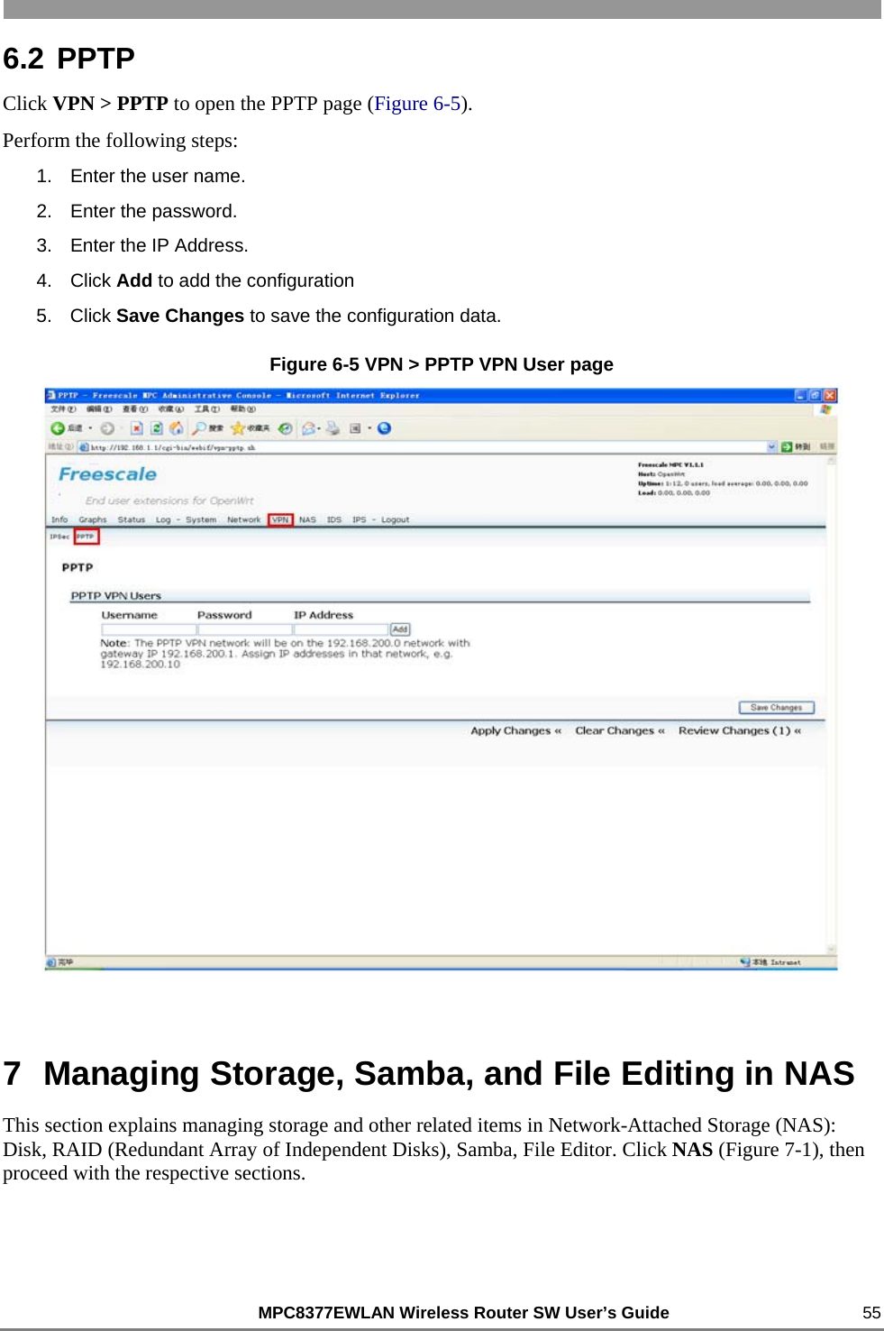
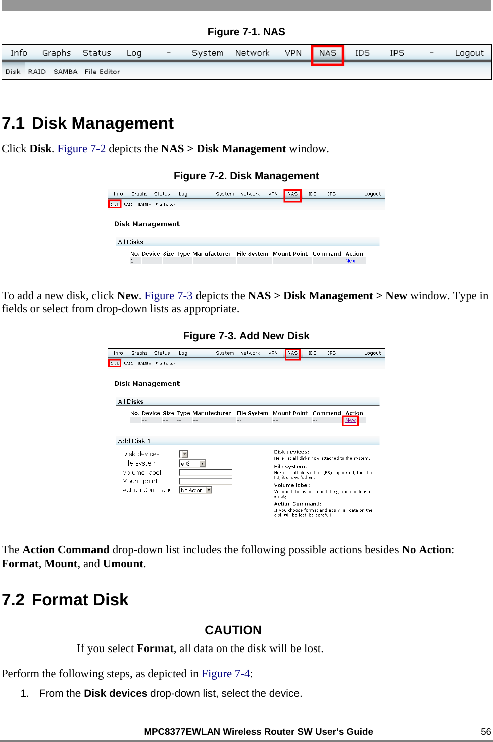
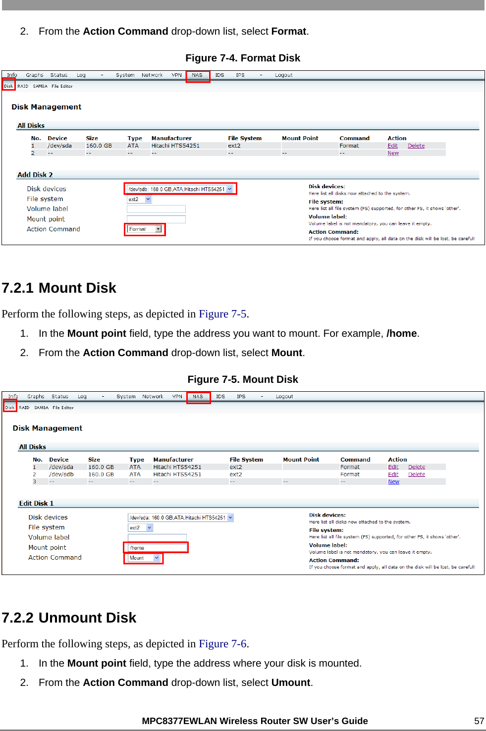
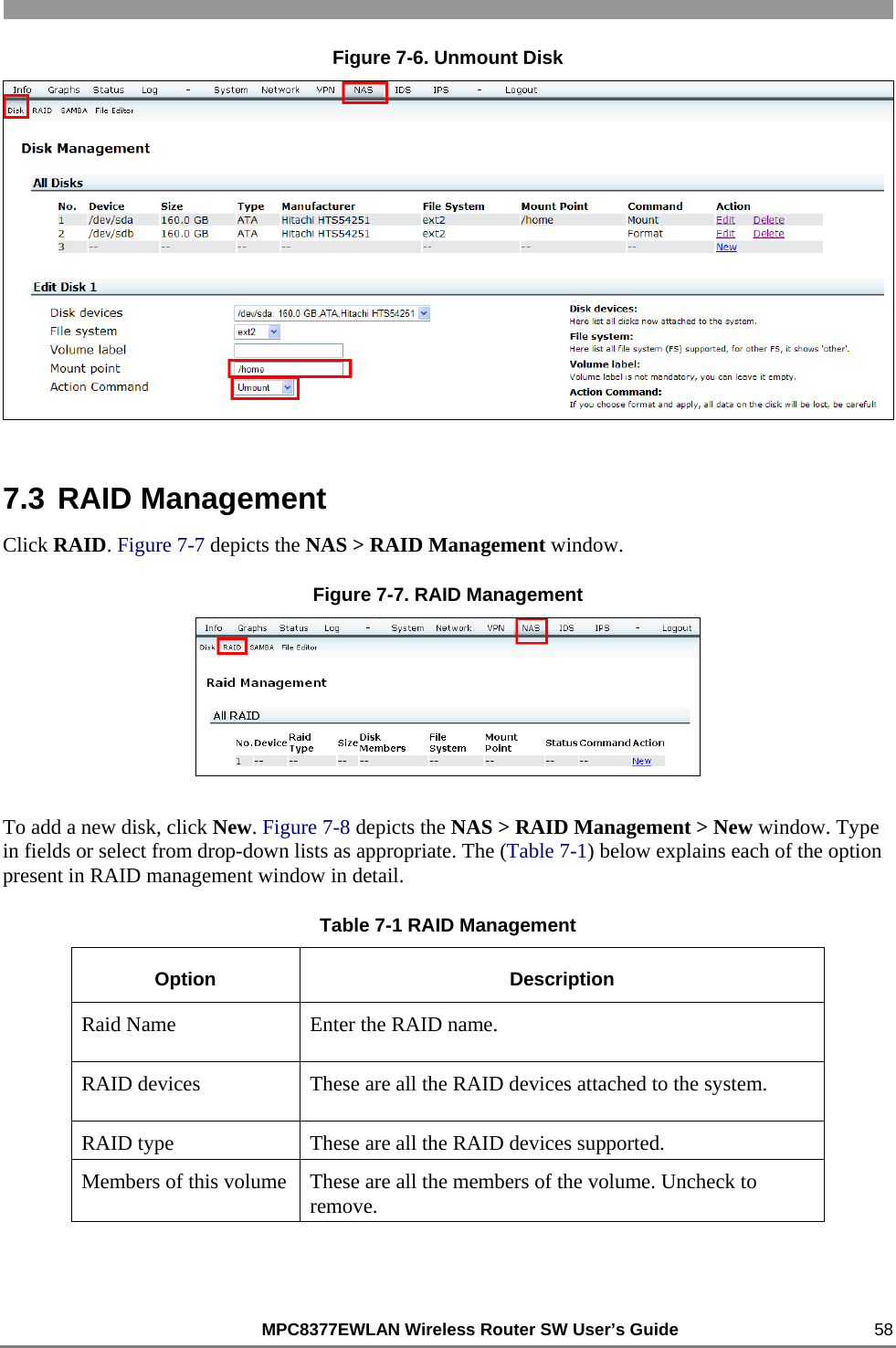
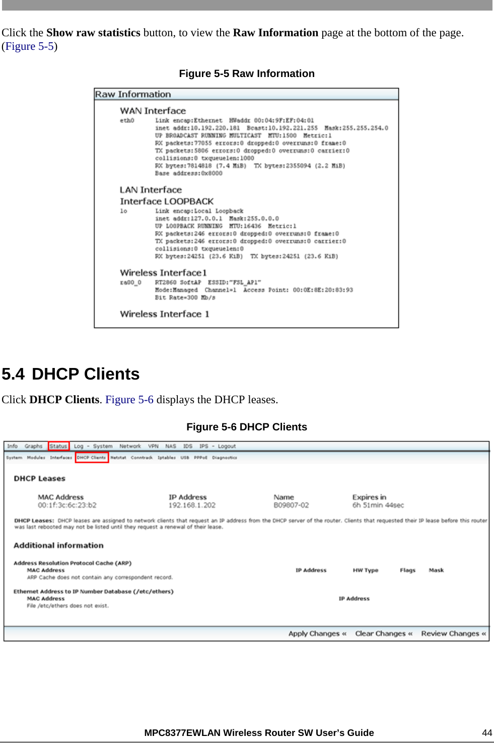
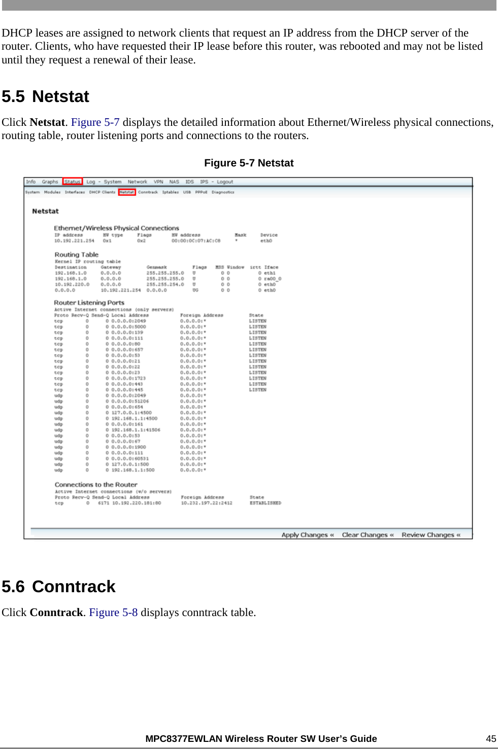
software part
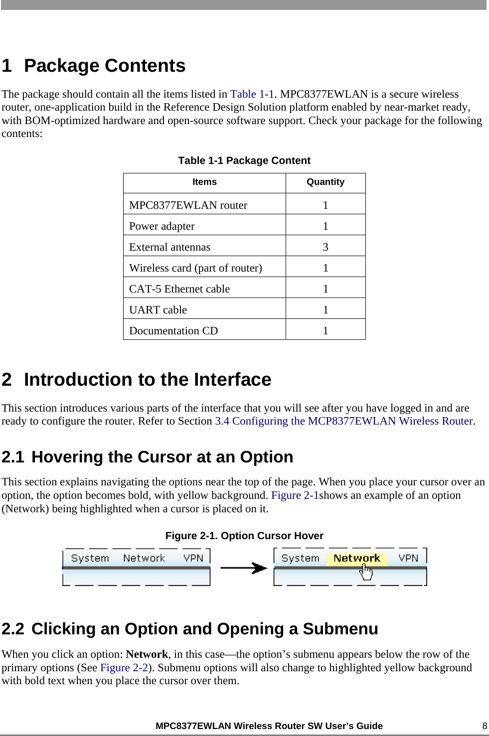
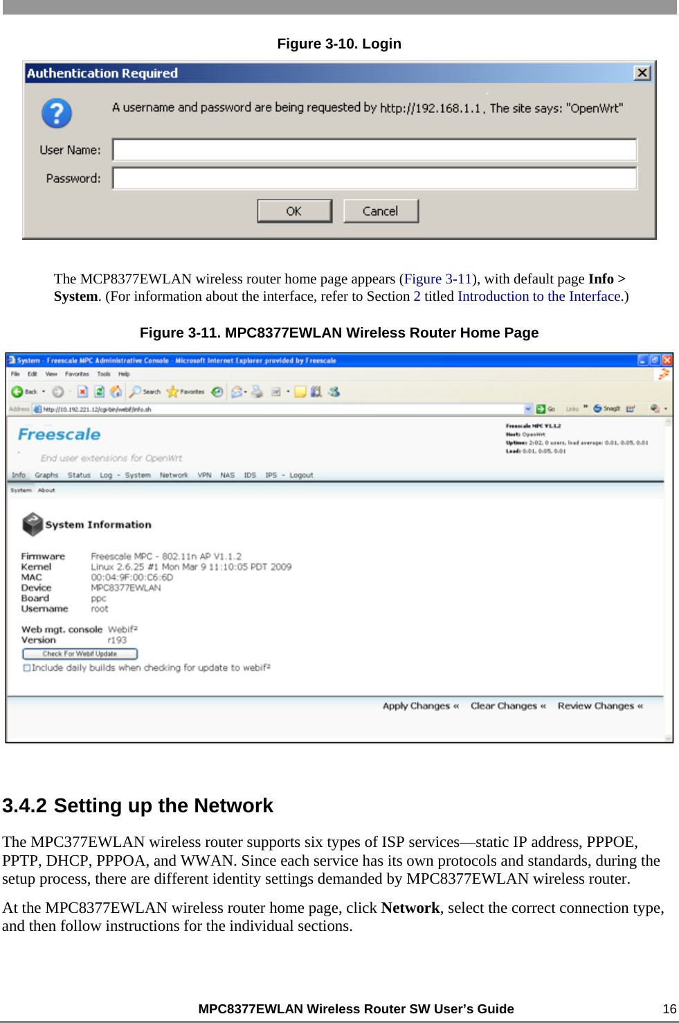
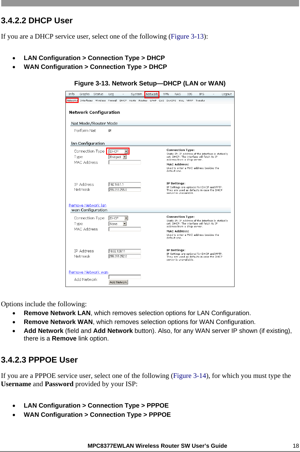
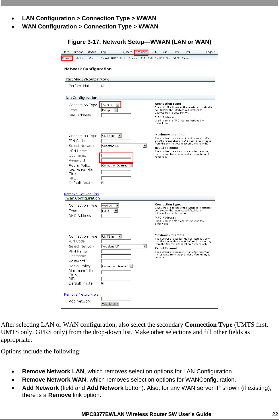
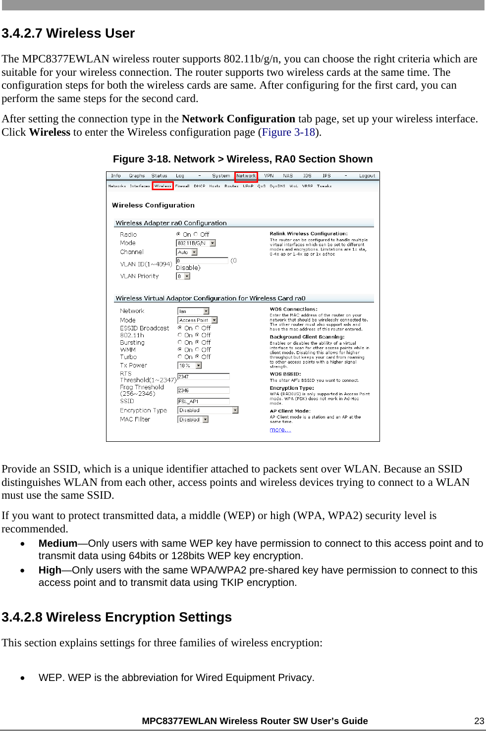
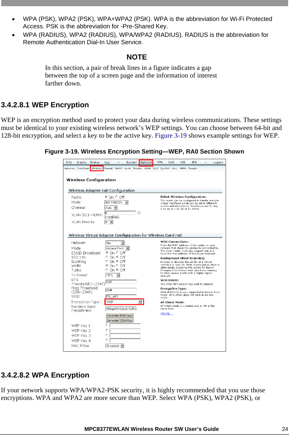
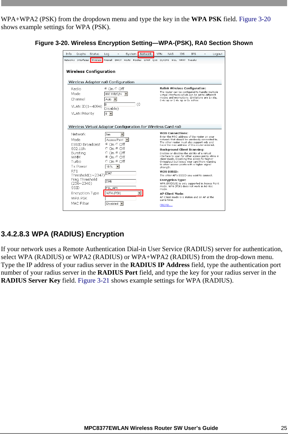
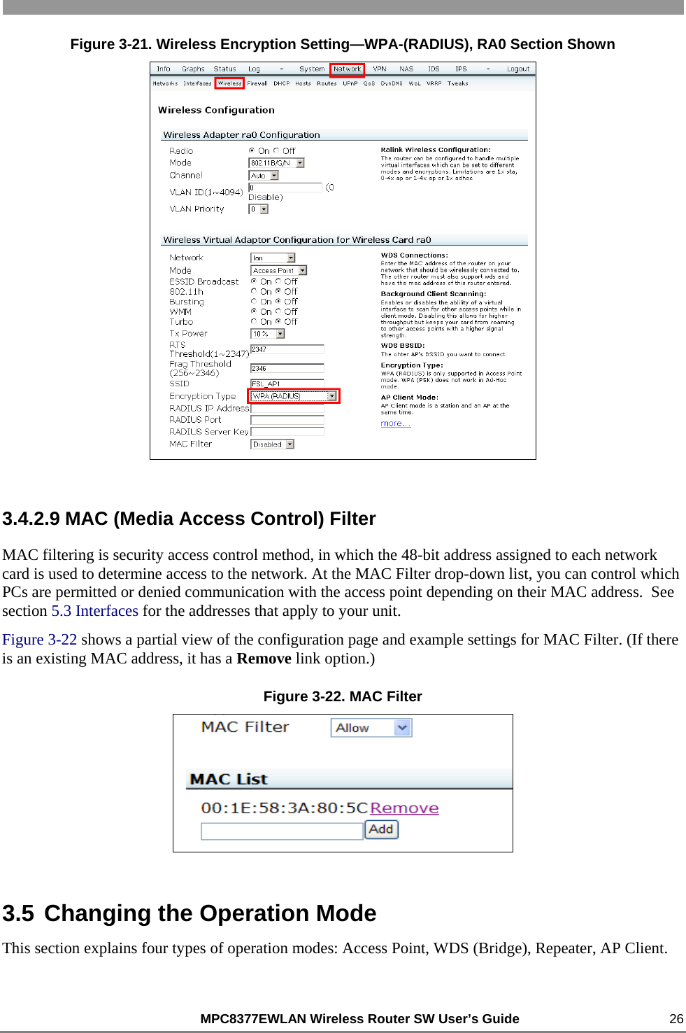
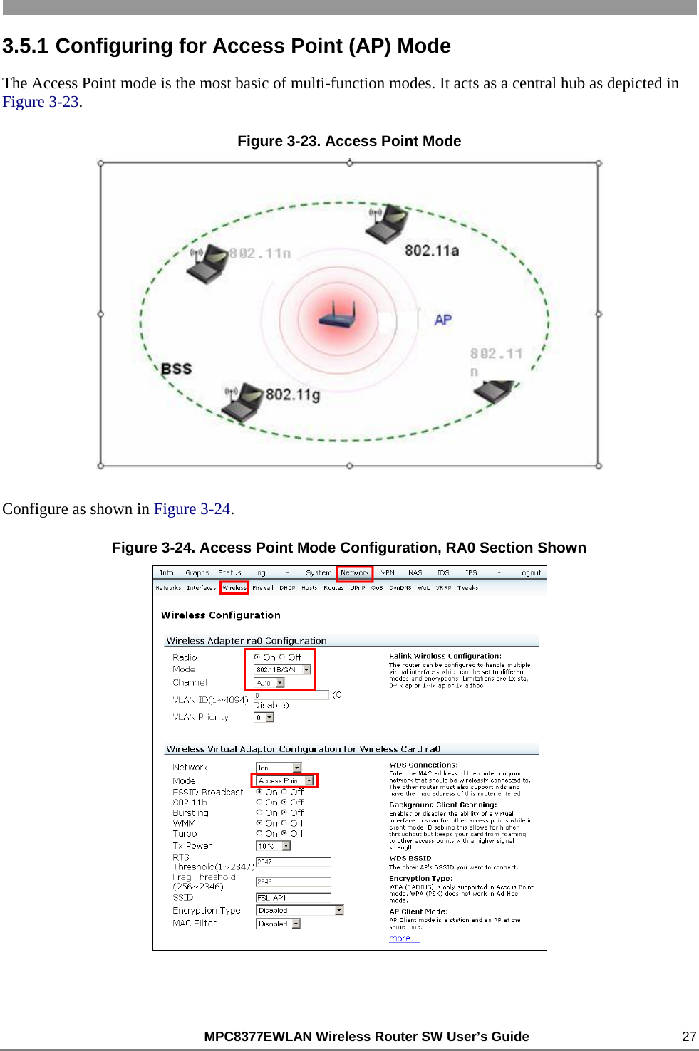
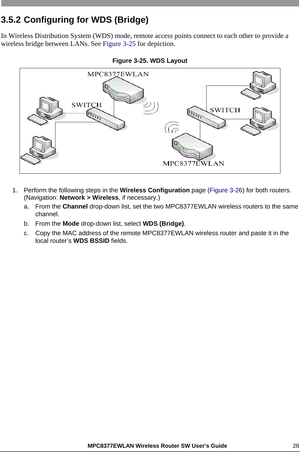
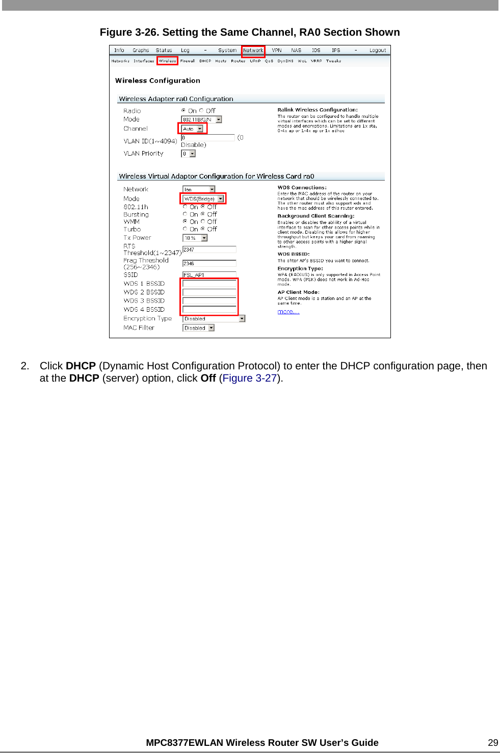

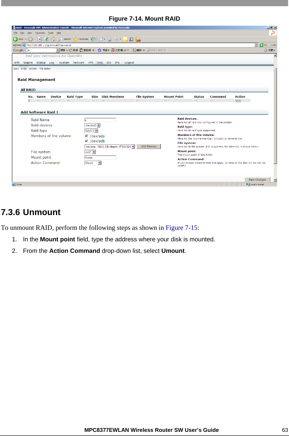
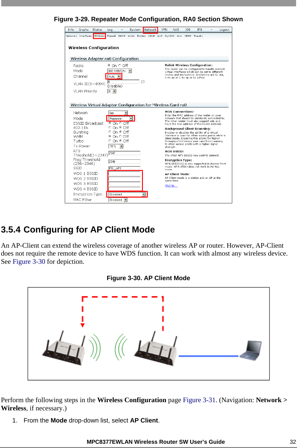
![MPC8377EWLAN Wireless Router SW User’s Guide 31 Figure 3-28. Repeater Mode Perform the following steps in the Wireless Configuration page Figure 3-29. (Navigation: Network > Wireless, if necessary.) 1. From the Channel drop-down list, select a channel to match the other EWLAN channel. (The channel setting must be the same for both EWLANs.) 2. From the Mode drop-down list, select Repeater. 3. In the SSID field, type the AP’s SSID. 4. In the WDS [n] BSSID fields, type the other WDS AP’s BSSIDs. (Format: xx:xx:xx:xx:xx:xx) 5. From the Encryption Type drop-down list, select the AP’s encryption.](https://usermanual.wiki/Freescale-Semiconductor/MPC8377EWLAN.software-part/User-Guide-1098087-Page-31.png)
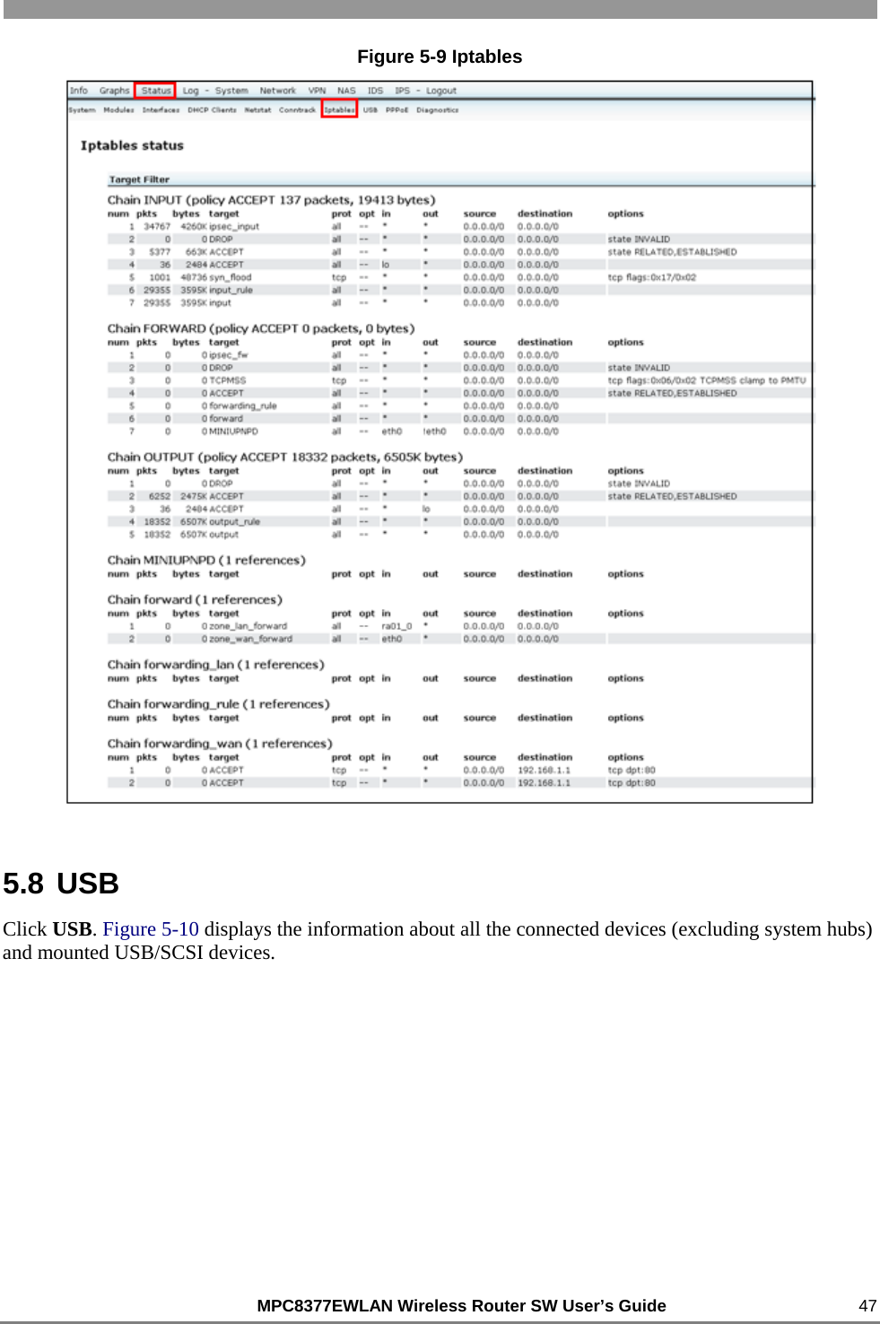
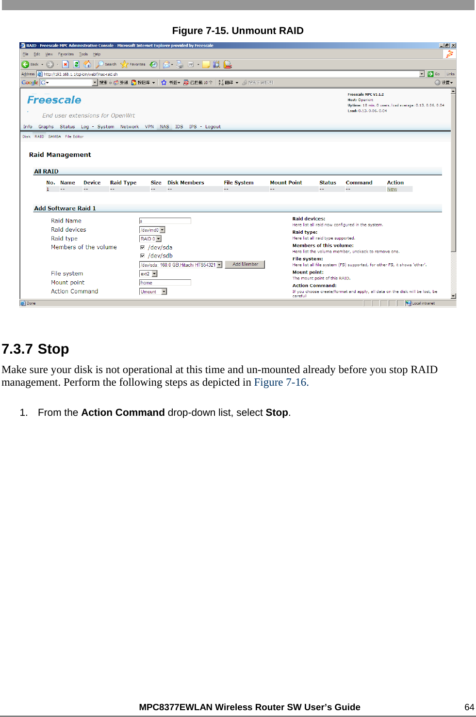
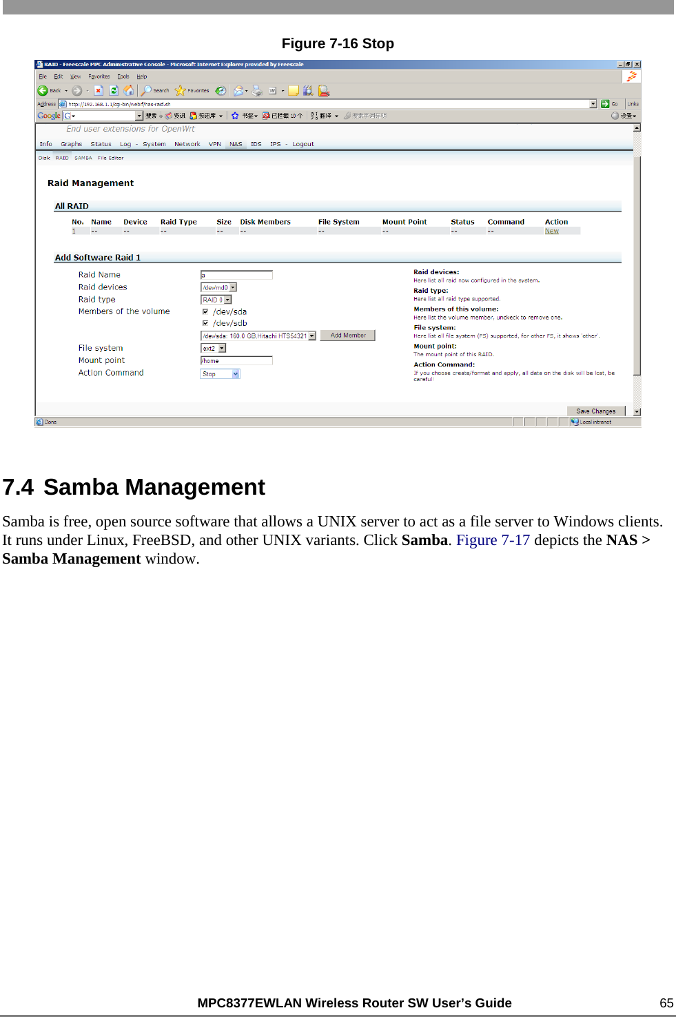
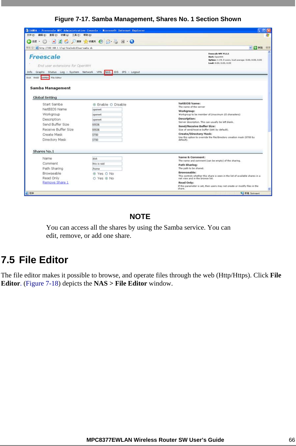
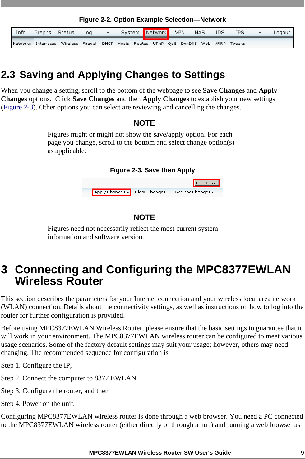
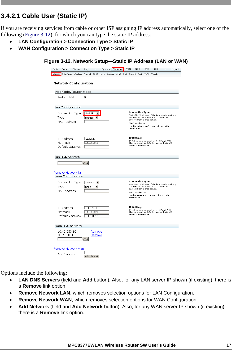
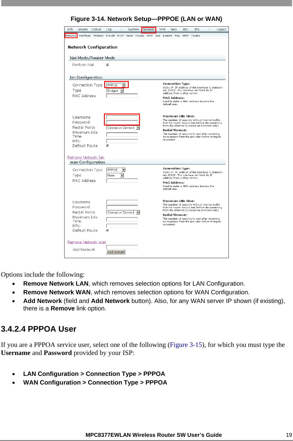
![MPC8377EWLAN Wireless Router SW User’s Guide 46 Figure 5-8 Conntrack 1. Insert a string to include or exclude in the Text to Filter text box. You can also type the regular expression constants like: 00:[[:digit:]]{2}:[[:digit:]]{2} or debug|.err 2. From the Filter Mode drop-down list, select Include or Exclude option. 3. Click Remove Filter button to remove the filter option that you have selected. 4. Click Filter Records button to filter the records. 5.7 Iptables Click Iptables. Figure 5-9 displays iptables status.](https://usermanual.wiki/Freescale-Semiconductor/MPC8377EWLAN.software-part/User-Guide-1098087-Page-46.png)