Freescale Semiconductor ZT3 Zigbee Data Device User Manual ZSTAR3RM
Freescale Semiconductor, Inc. Zigbee Data Device ZSTAR3RM
UserManual.wiki
>
Freescale Semiconductor
>
ZT3 User Manual
Manual
Navigation menu
Upload a User Manual
Namespaces
Wiki Guide
HTML
PDF
Info
Views
User Manual
Discussion / Help
Navigation
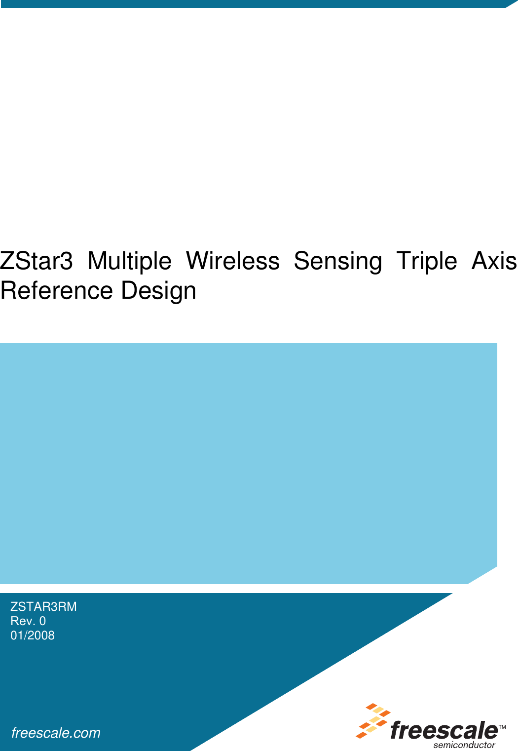
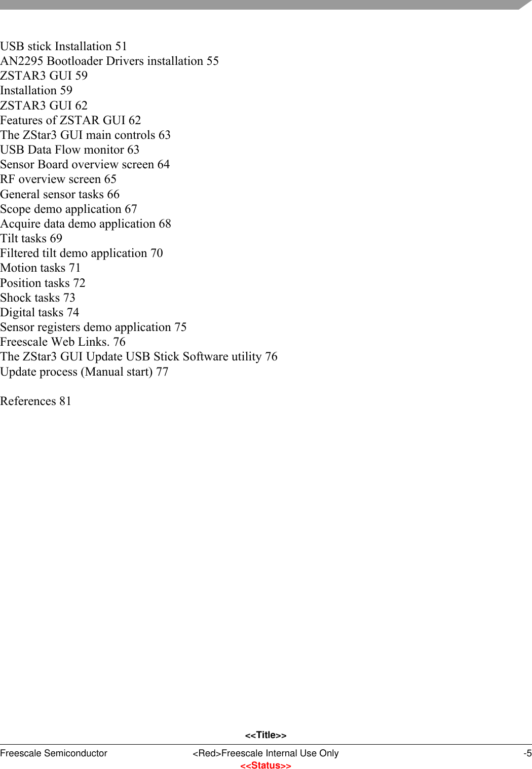

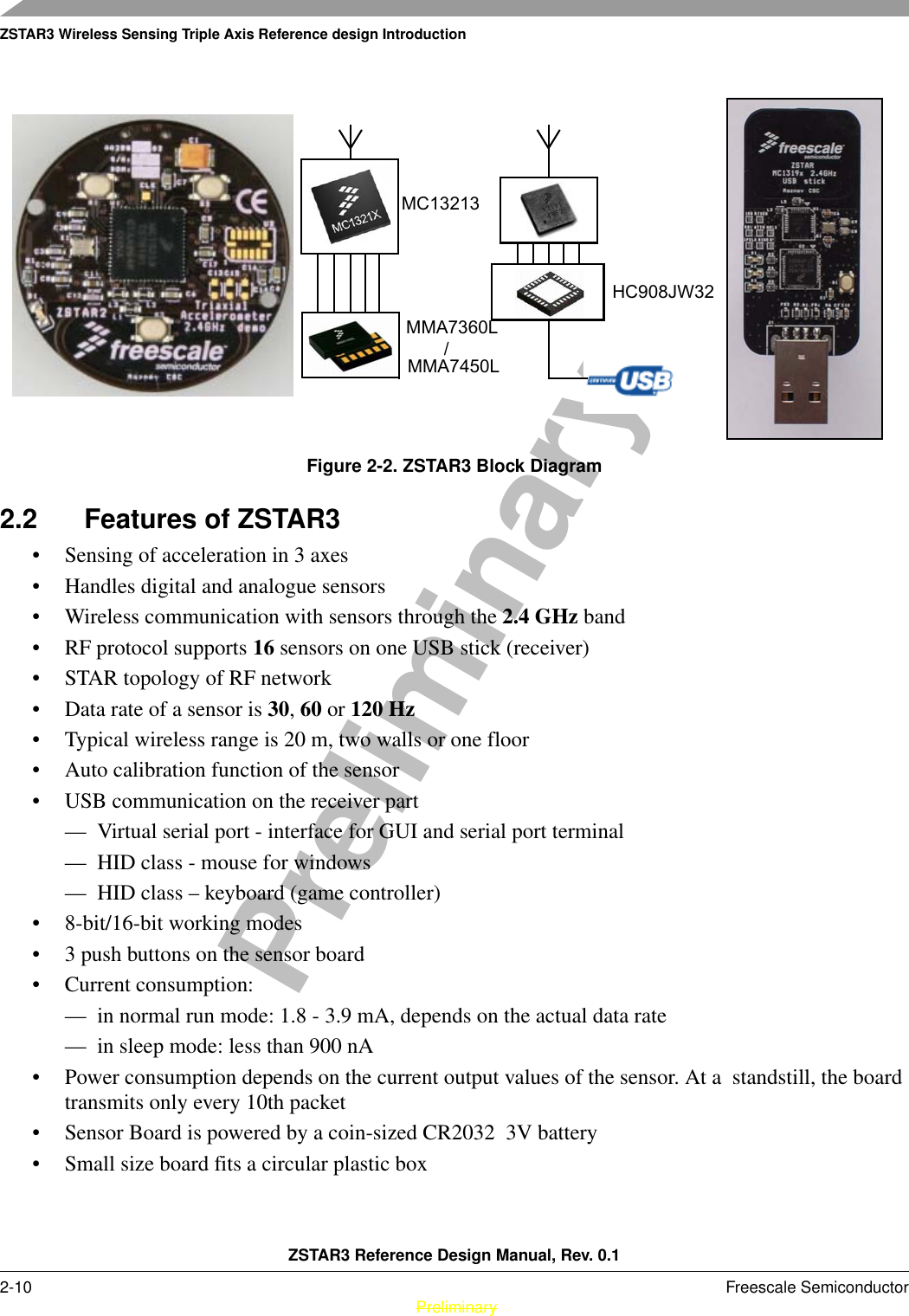
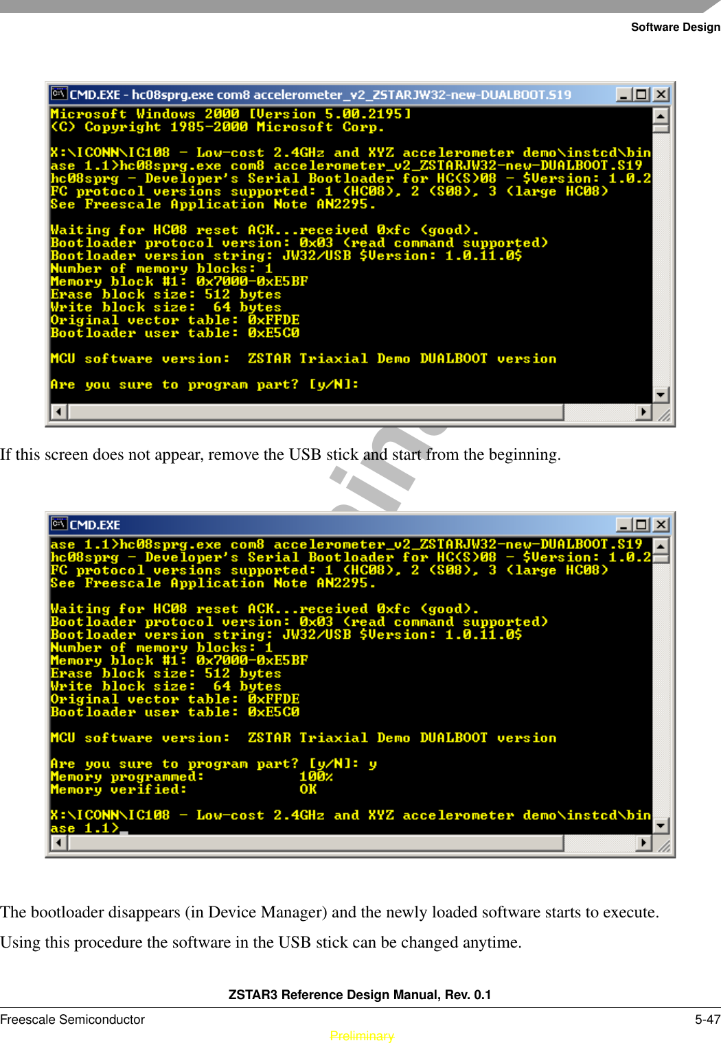
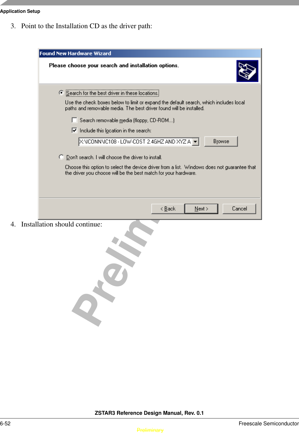
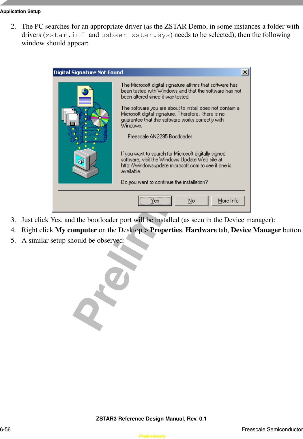
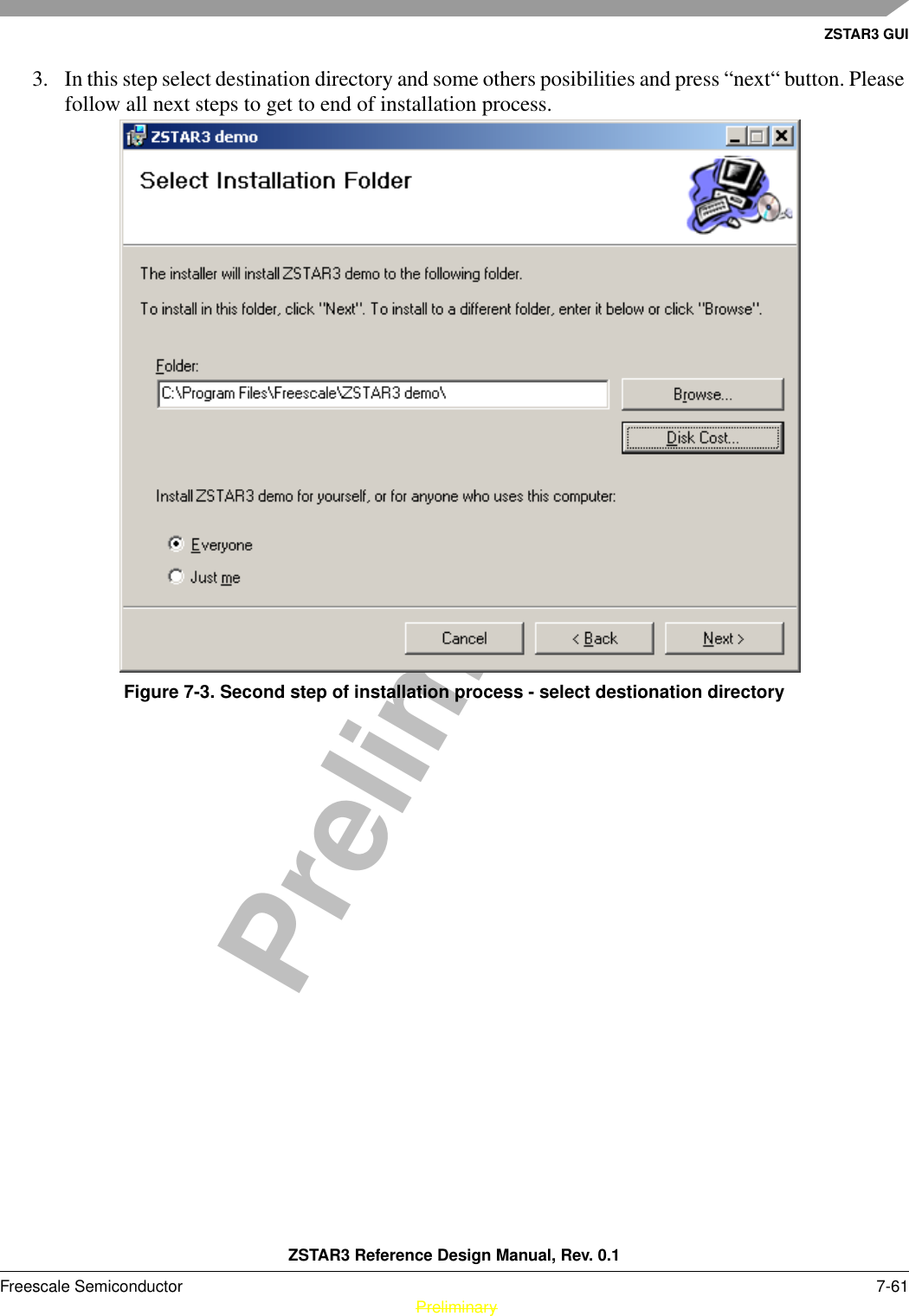
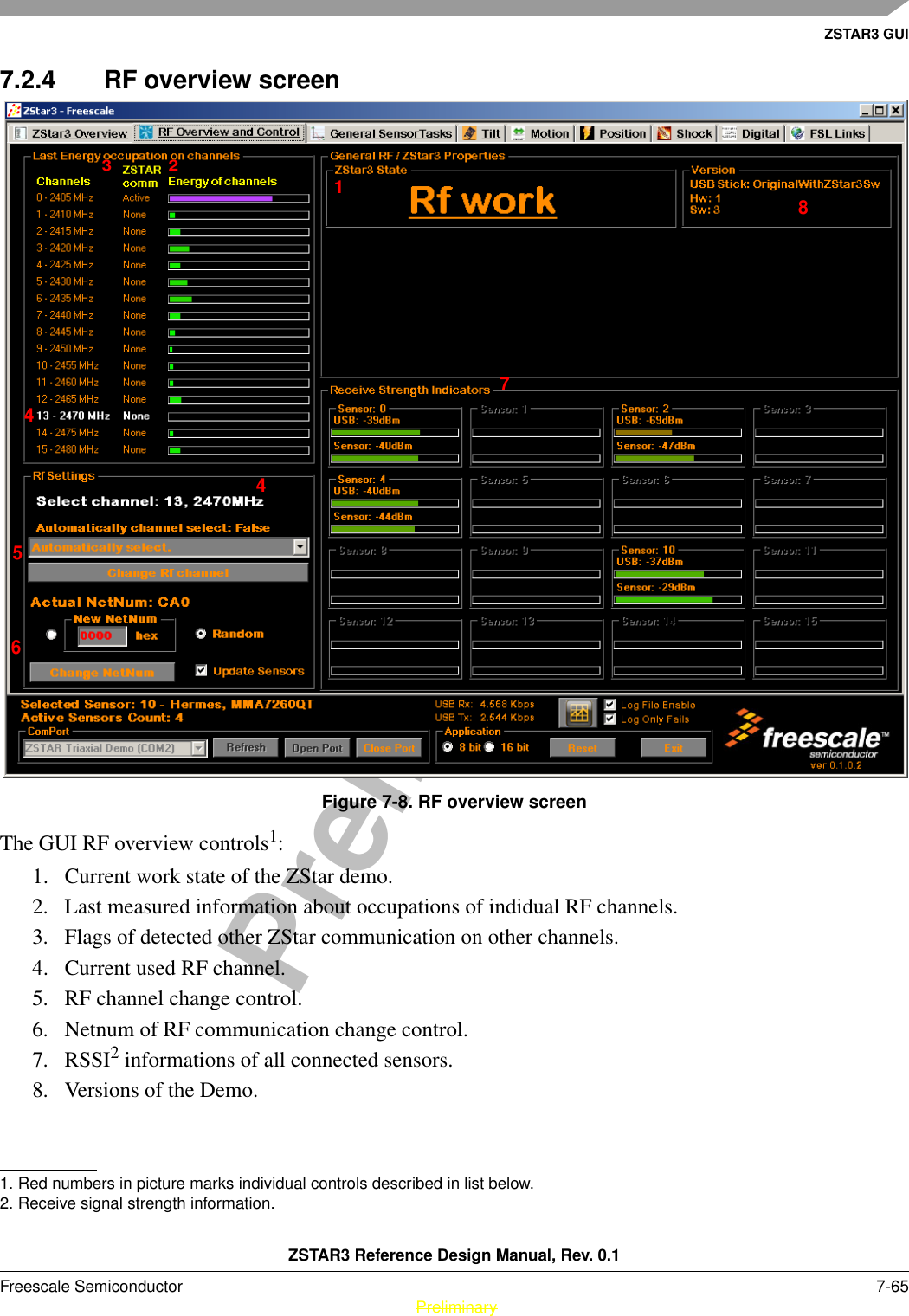
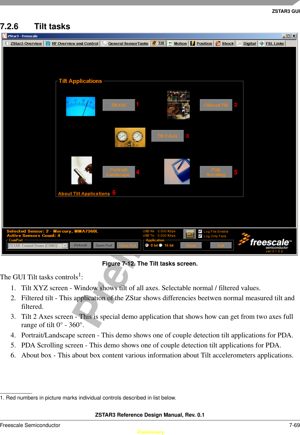
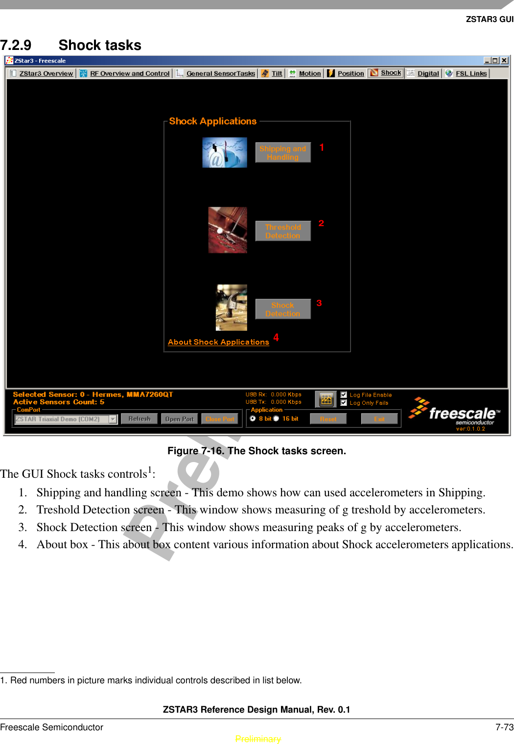
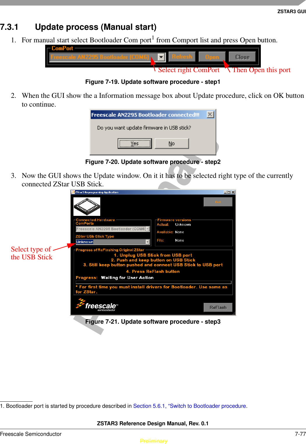
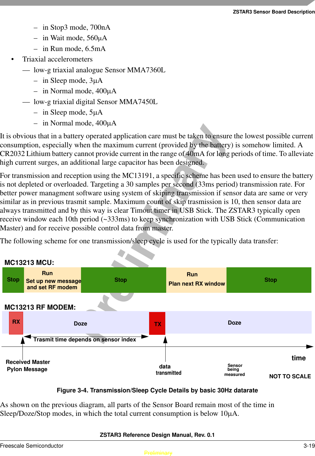
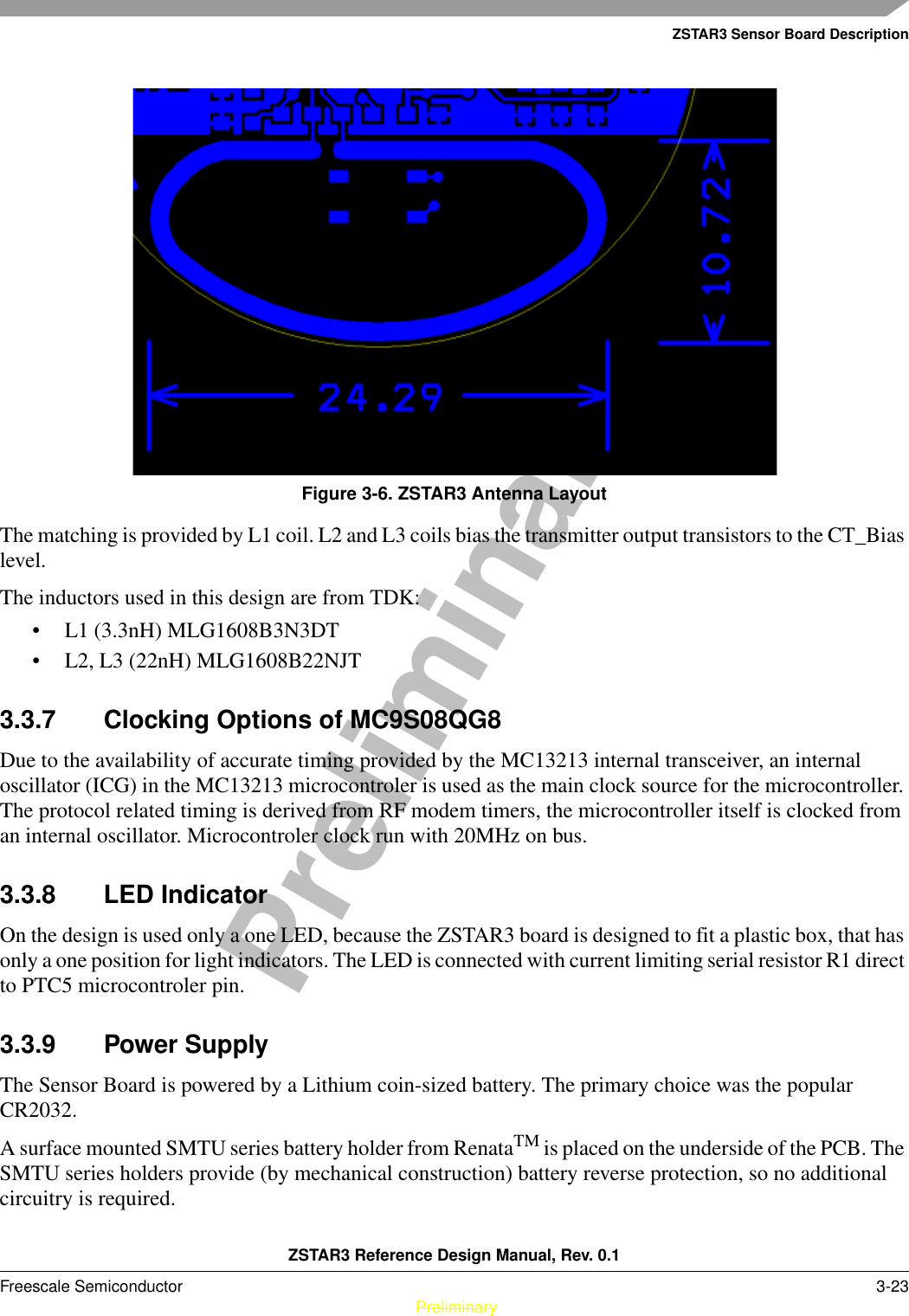
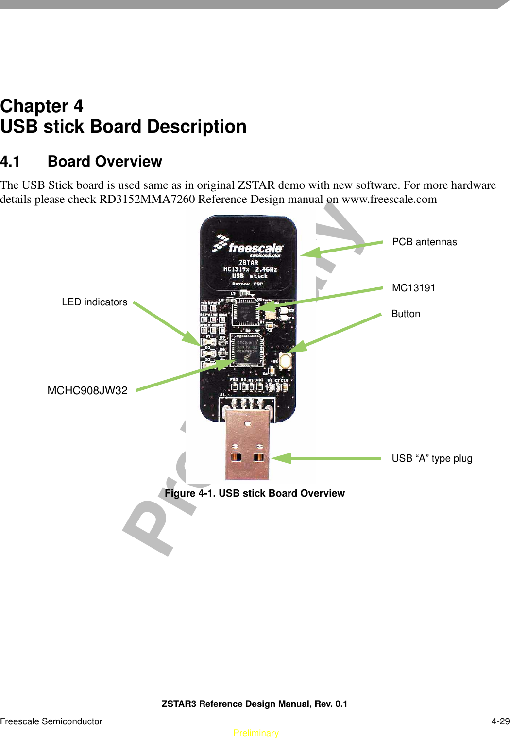
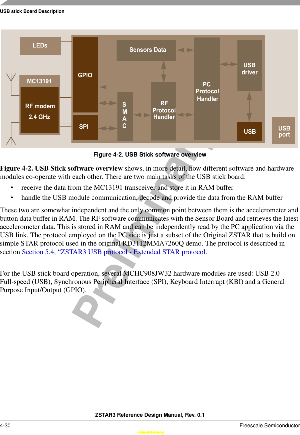
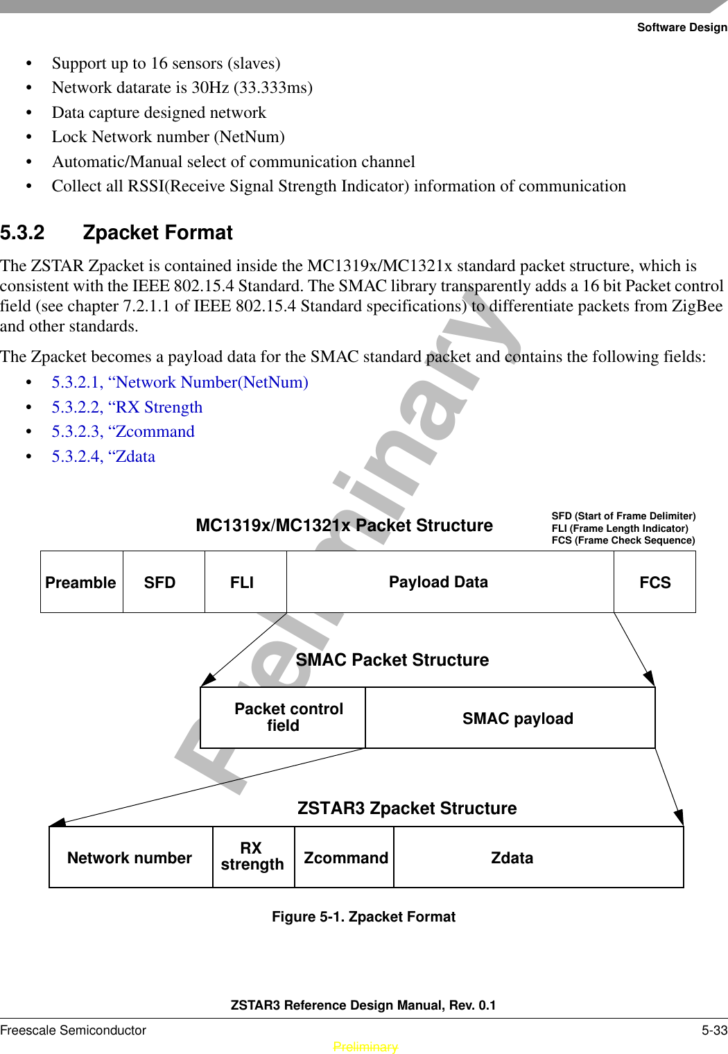
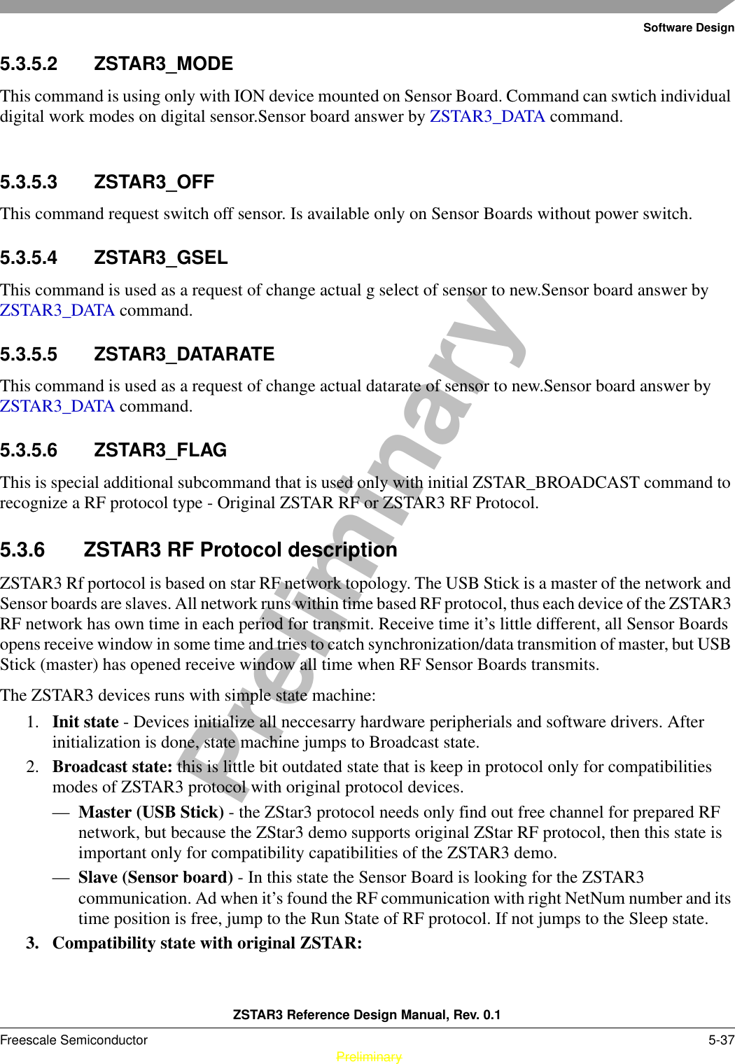
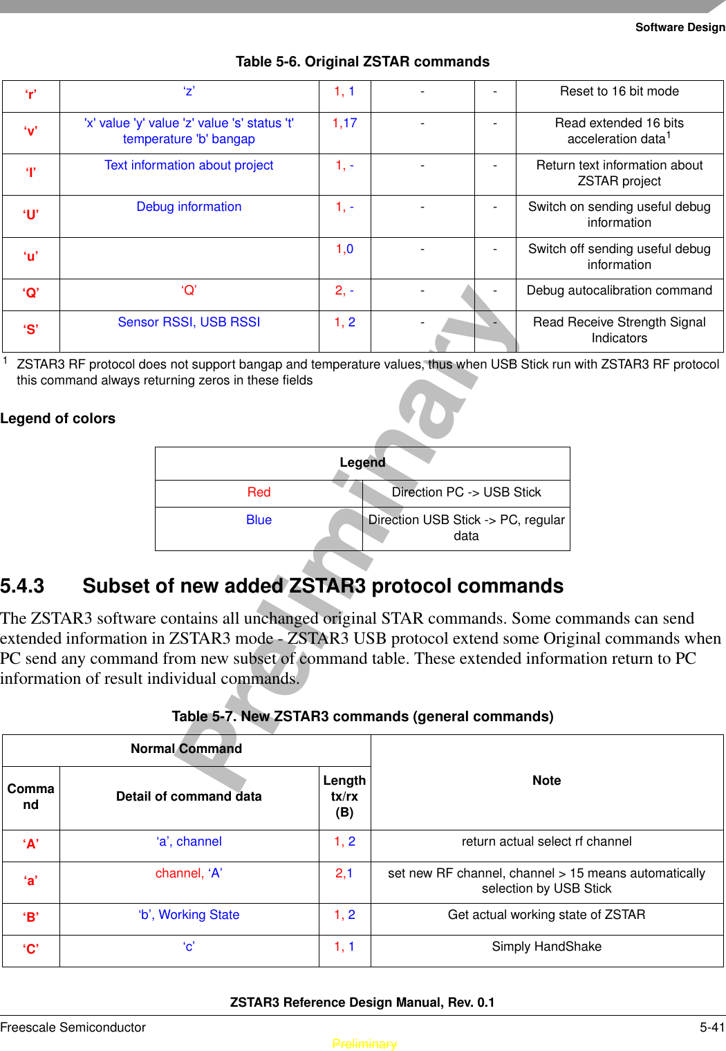
![ZSTAR3 Sensor Board DescriptionZSTAR3 Reference Design Manual, Rev. 0.1Freescale Semiconductor 3-17 PreliminaryPreliminaryFigure 3-3. ZSTAR3 Sensor Board Software OverviewFor the Sensor Board operation, several of the MC13213’s hardware modules are used: Analog to Digital Converter (ADC), Synchronous Peripheral Interface (SPI), External Interrupt Request (IRQ), Keyboard Interrupts and General Purpose Input/Output (GPIO).3.2 Accelerometric sensor sw controllerReading of XYZ levels and all others operation with sensor is depends on current assembled sensor. The ZSTAR3 sensor board supports two types of Freescale accelerometric sensors, analogue(MMA736xLT) and digital(MMA745xL). Assembly sensor is powered by IO pins of MCU, this solution allow reach a lowest power consumtion in sleep mode.3.2.1 Double sensor support software modelAll common control functions of sensor are physically create as two individual function. First for analogue and second for digital sensor. Main software is using only volatile pointers on this function, that are assigned within initialization of program, by ” Recognise_Sensor() “ function. This function recognises an assembled sensor and assigns right functions address to volatile RAM pointers. For example, by this way analogue sensor is using ADC to read XYZ values of sensor and digital sensor is using digital interface, but in source code are only one line: p_Read_Accelerometer((void*) &(accel_data[0].x)).3.2.2 Autocalibration processThe software uses for both types of sensor autocalibration process to get offset calibration values. It uses a simple 0g X, 0g Y, +1g Z acceleration method. The sensor board runs autocalibration process for each g scale of sensor, and thus uses for each g scale induvidual set of calibration values. For more details see GPIOADCKBISensorButtonsGPIOSensor data collectorDatabuffer RFmodem2.4GHzSMACLEDRFProtocolHandleranddriver](https://usermanual.wiki/Freescale-Semiconductor/ZT3/User-Guide-924065-Page-17.png)
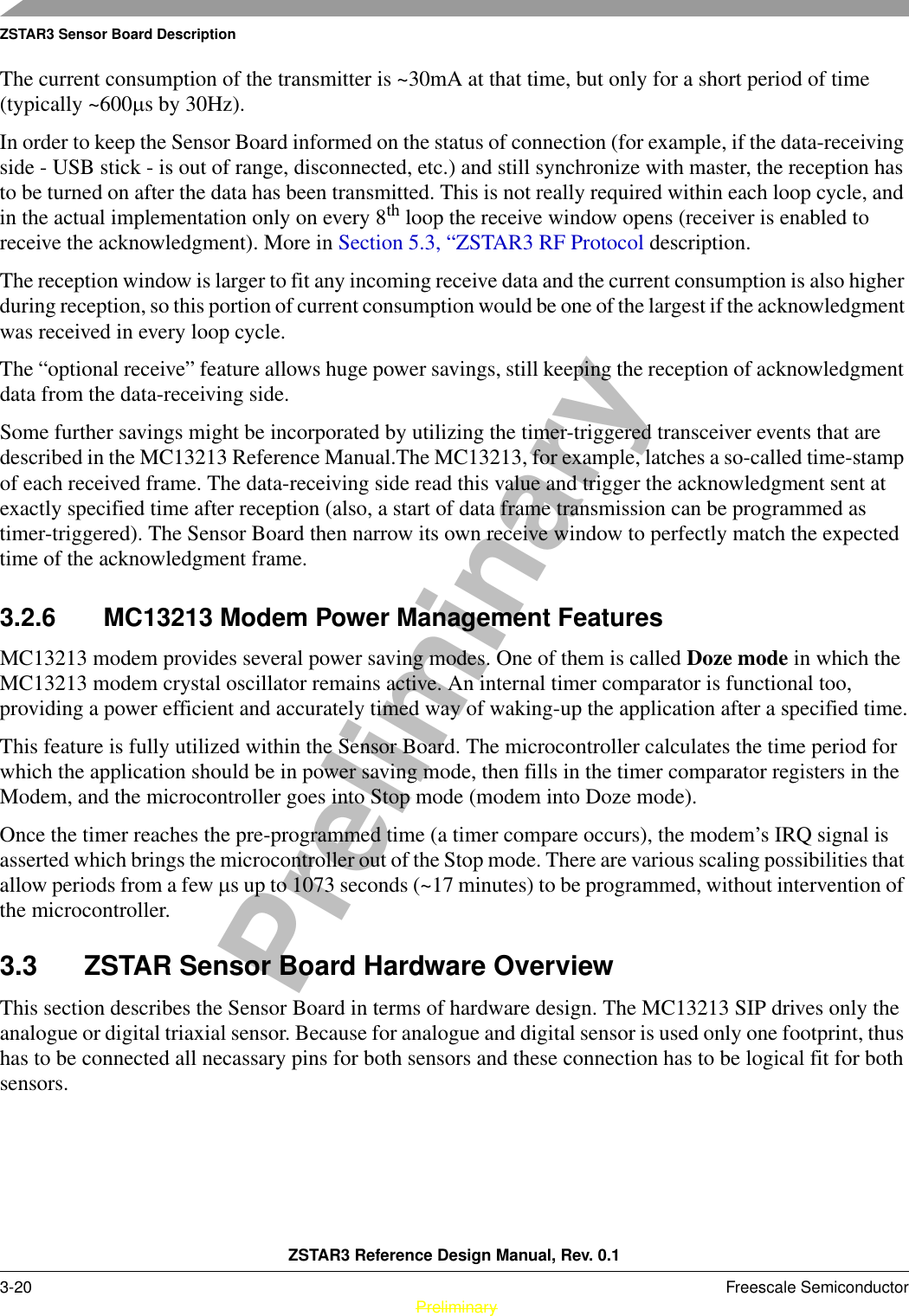


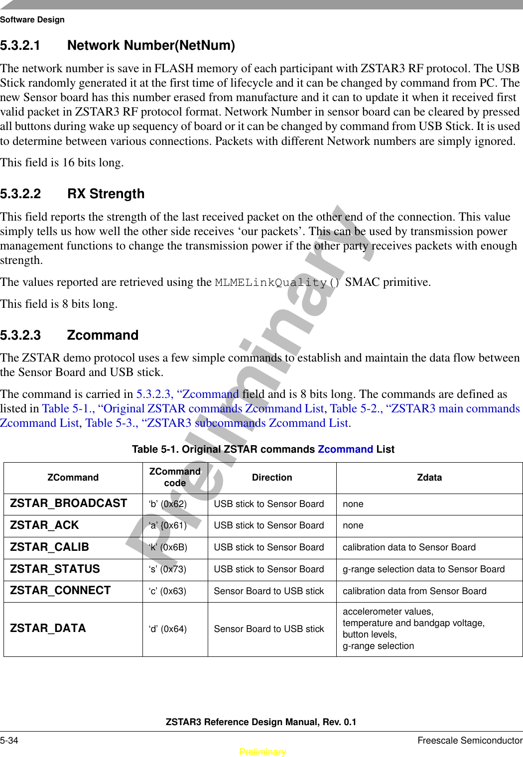
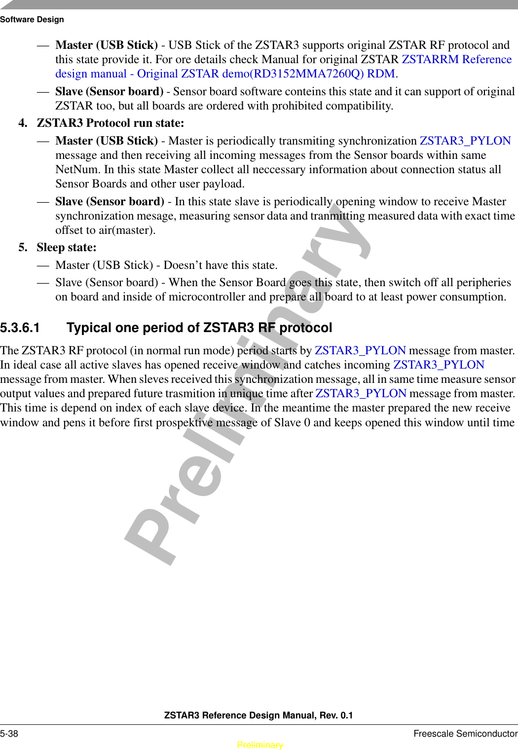
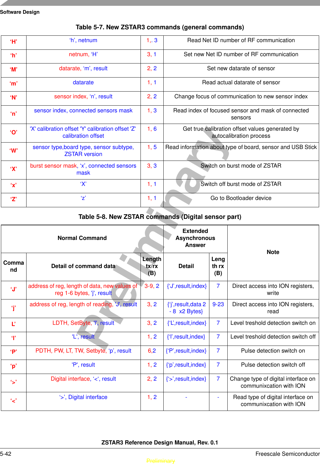
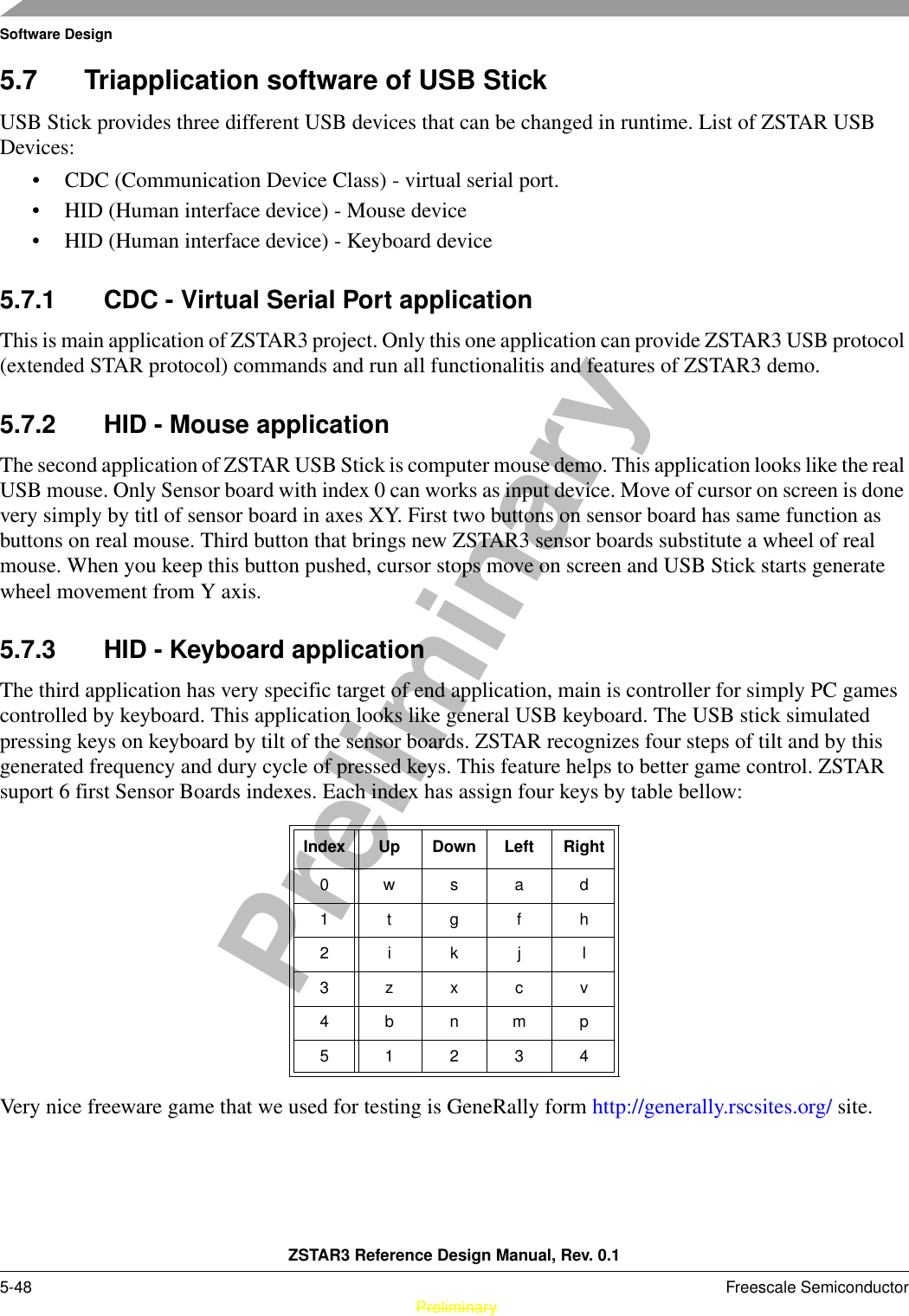
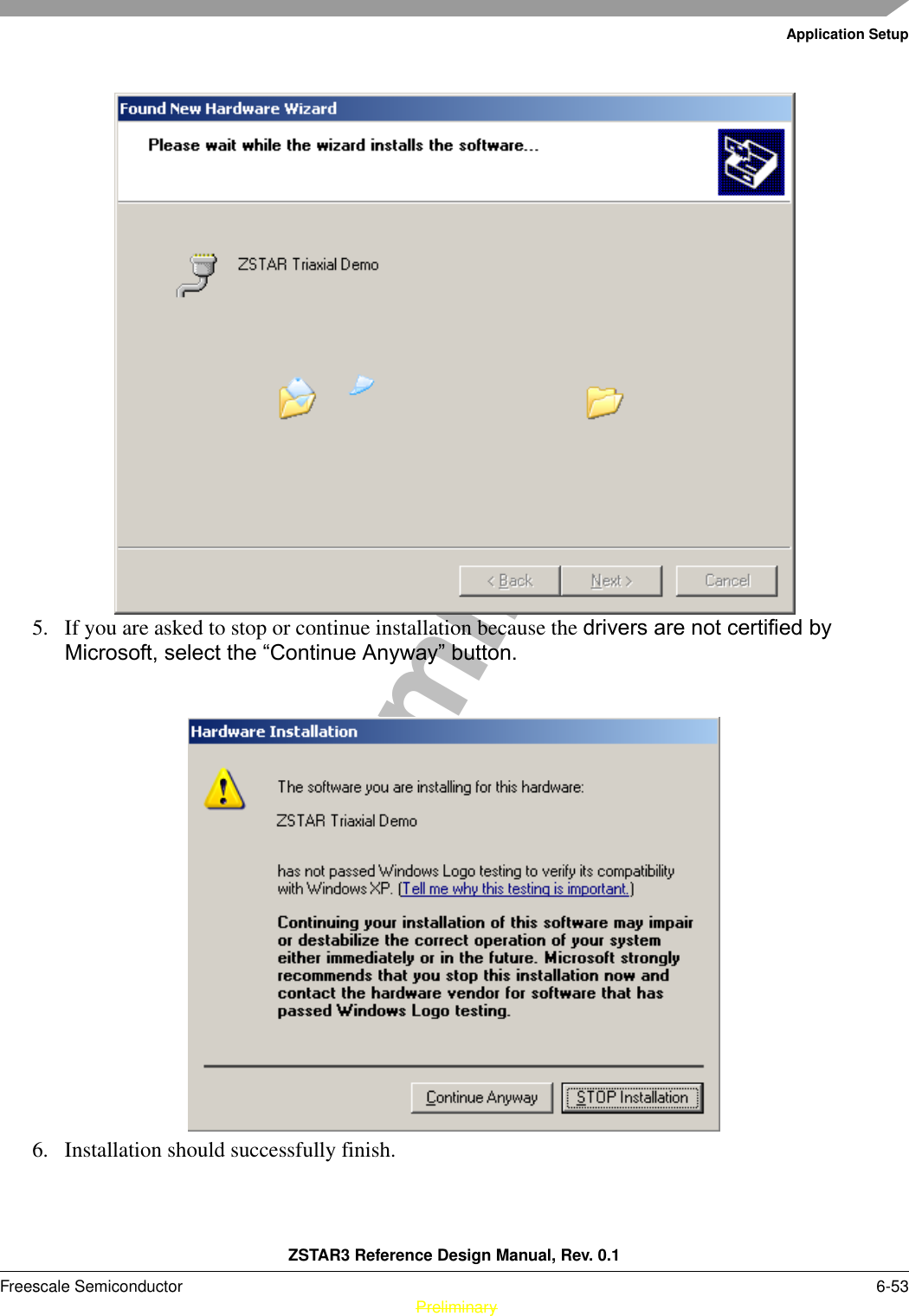
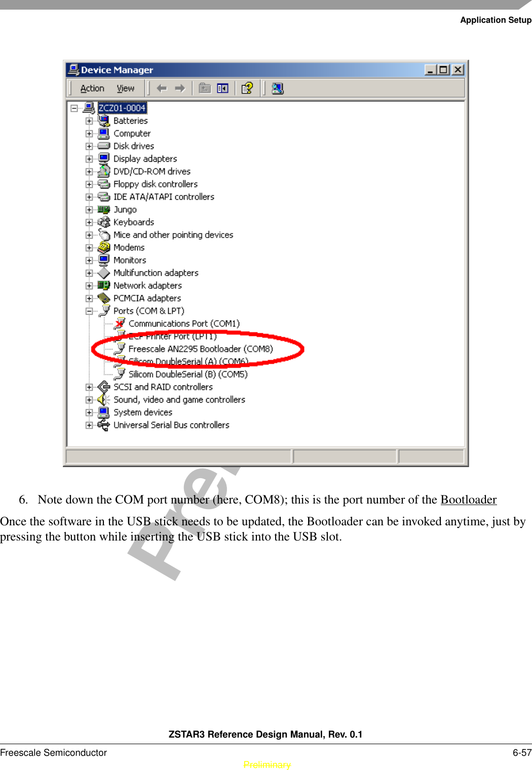
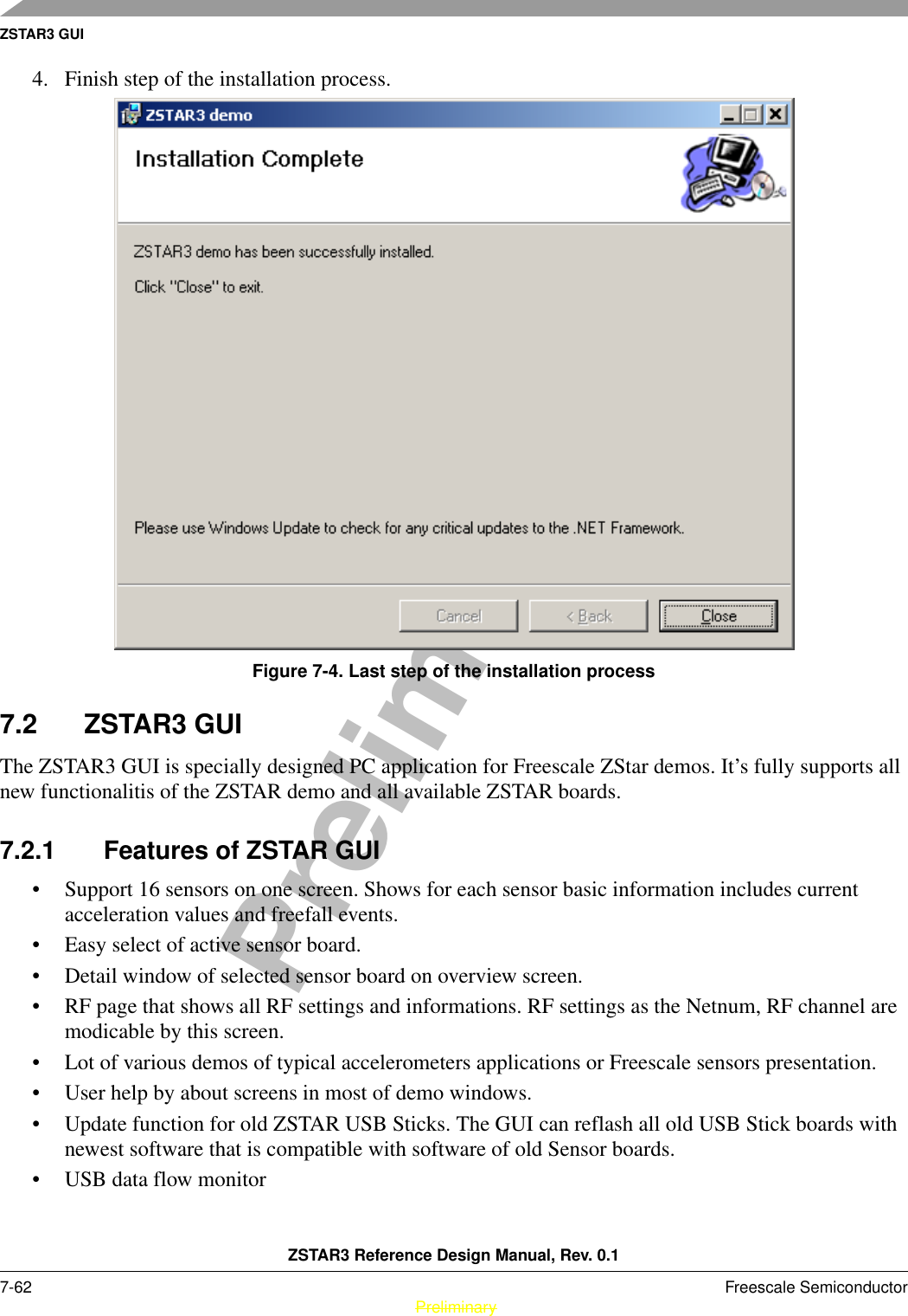
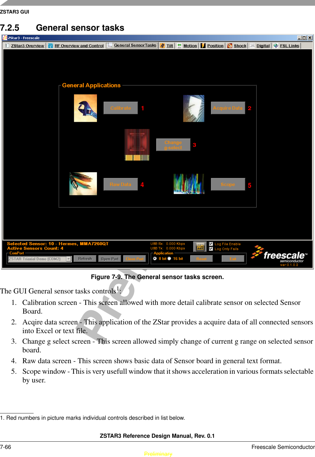
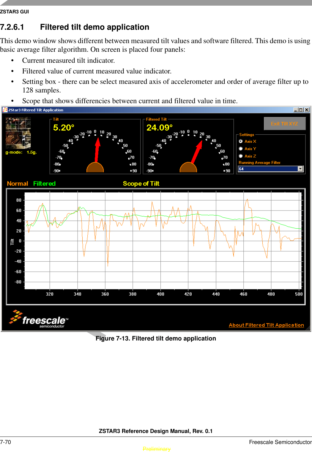
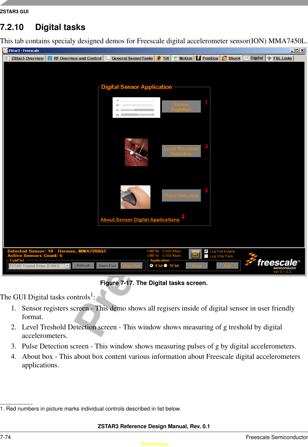
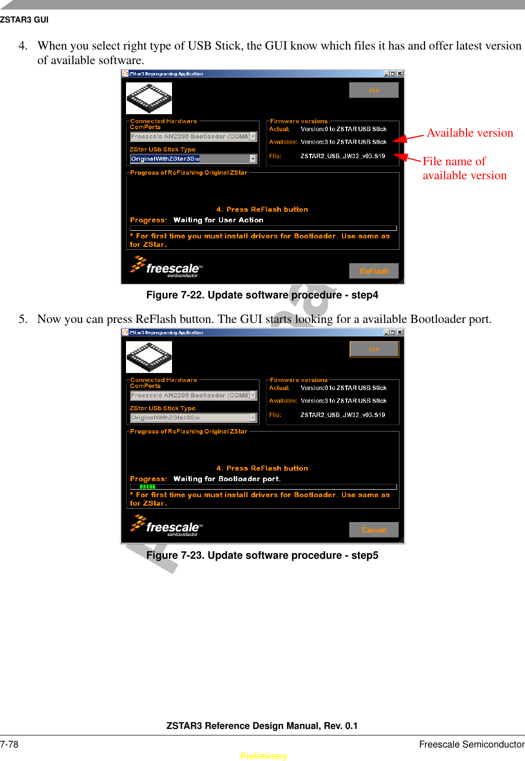
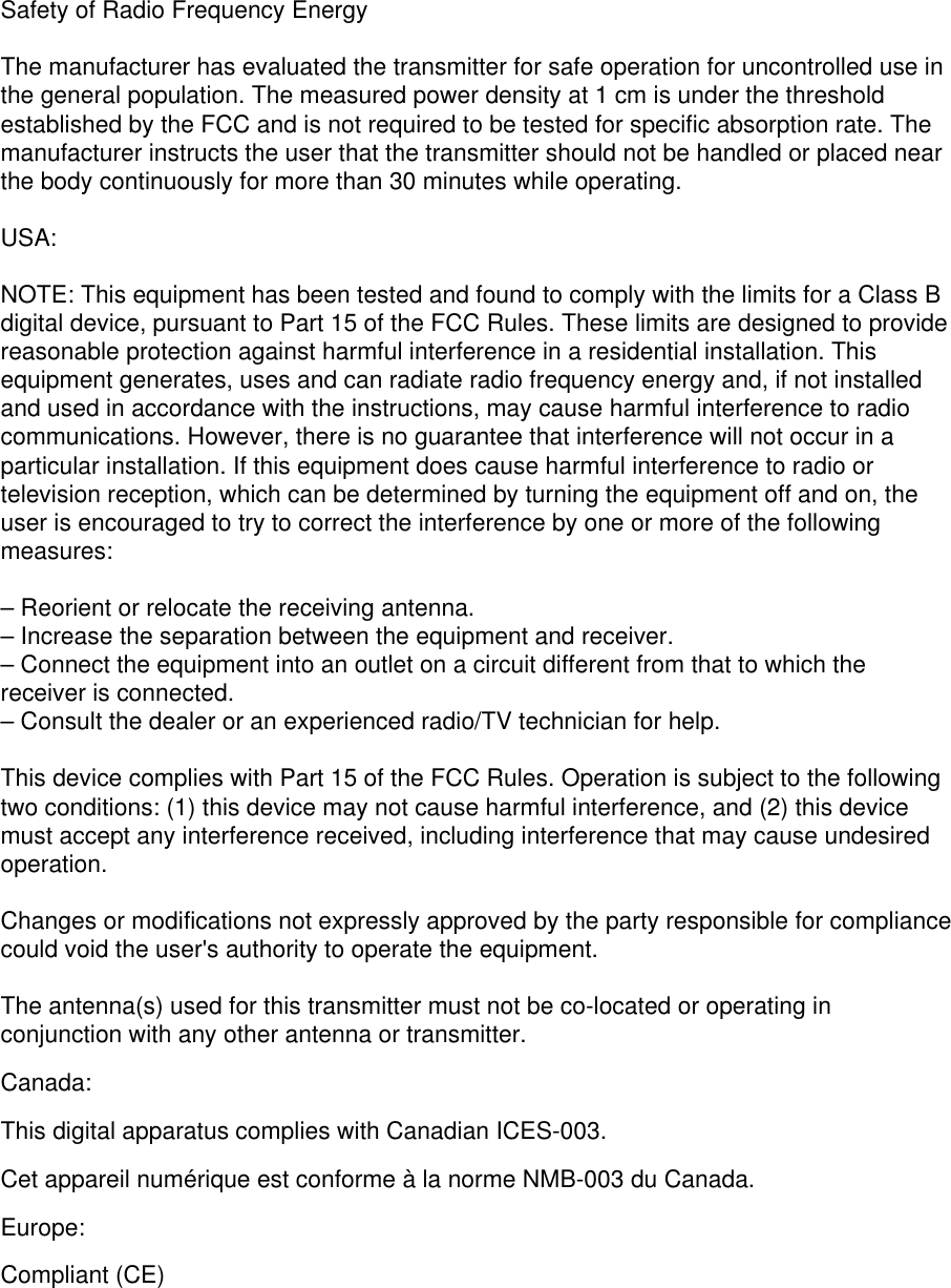
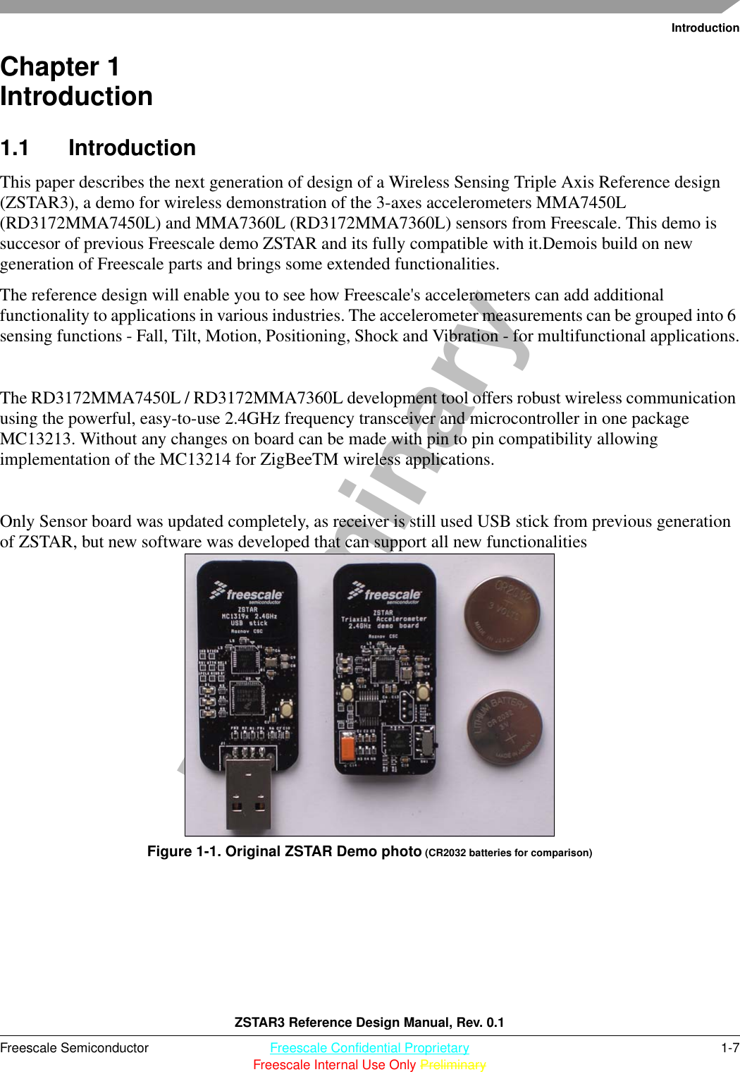
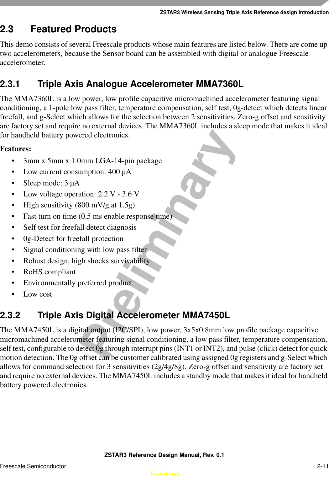
![Software DesignZSTAR3 Reference Design Manual, Rev. 0.1Freescale Semiconductor 5-43 PreliminaryPreliminaryTable 5-9. Legend of colors5.4.4 Burst modeA new mode of ZSTAR USB communication is burst mode. The Burst mode is designed to symplification reading process of new acceleration data. In burst mode USB Stick is sending all new received acceleration data from individual enabled sensor boards without any request command from PC.Burst mode content:• time of receive - 24bits time information with 4 us step• manage byte - contain actual datarate, mode 8/16bits and index of Sensor board• acceleration data + data status - this field can be multiply repeat up to 4 samples depends on actual datarate• Status - contains information about select g range, buttons and events of last sampleBurst mode frame formats examples:[ttttttmmxxyyzzddss] - 8 bits 30Hz frame[ttttttmmxxxxyyyyzzzzddss] - 16 bits 30Hz frame[ttttttmmxxxxyyyyzzzzddxxxxyyyyzzzzddxxxxyyyyzzzzddxxxxyyyyzzzzddss] - 16 bits 120Hz frame - worest case of communicationwhere is: t - receive time, m - manage byte, x- accelariotion in X axis, y- accelariotion in Y axis, z- accelariotion in Z axis, d - data status byte, s - frame status byte, [ - start char and ] is end char of frame.Real example of burst mode frame:”[BBBCDCA0D0001400400000D6002C00410000D9002D003D0000E1002F003D000020]”.5.4.5 Network Lock feature of ZSTAR3 protocolThe ZStar3 RF protocol brings a new network lock function.This feature allow provide more ZSTAR3 networks in one RF space. For more details check section 5.3.2.1, “Network Number(NetNum).5.4.6 Semiautomatic Self-CalibrationFor the purpose of easier semiautomatic calibration of the ZSTAR demo with out PC GUI, the additional Calibration command ‘Q’ (0x51) has been added. This command is usually issued over terminal (e.g. HyperTerminal) software.LegendRed Direction PC -> USB StickBlue Direction USB Stick -> PC, regular data](https://usermanual.wiki/Freescale-Semiconductor/ZT3/User-Guide-924065-Page-43.png)
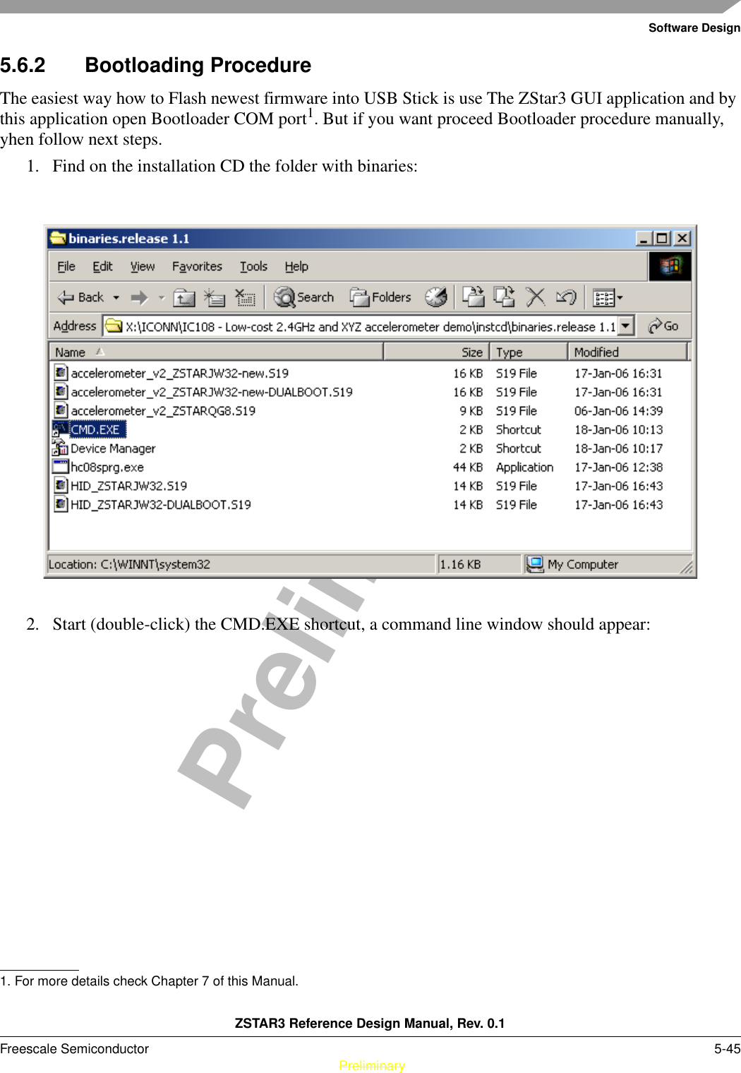
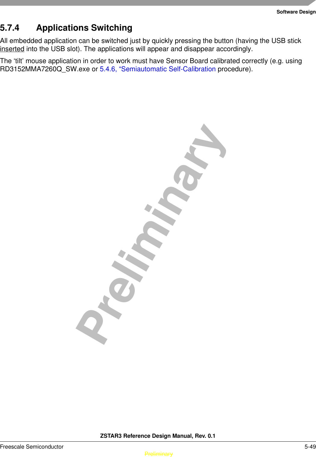
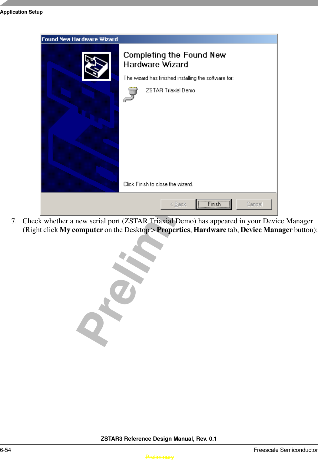
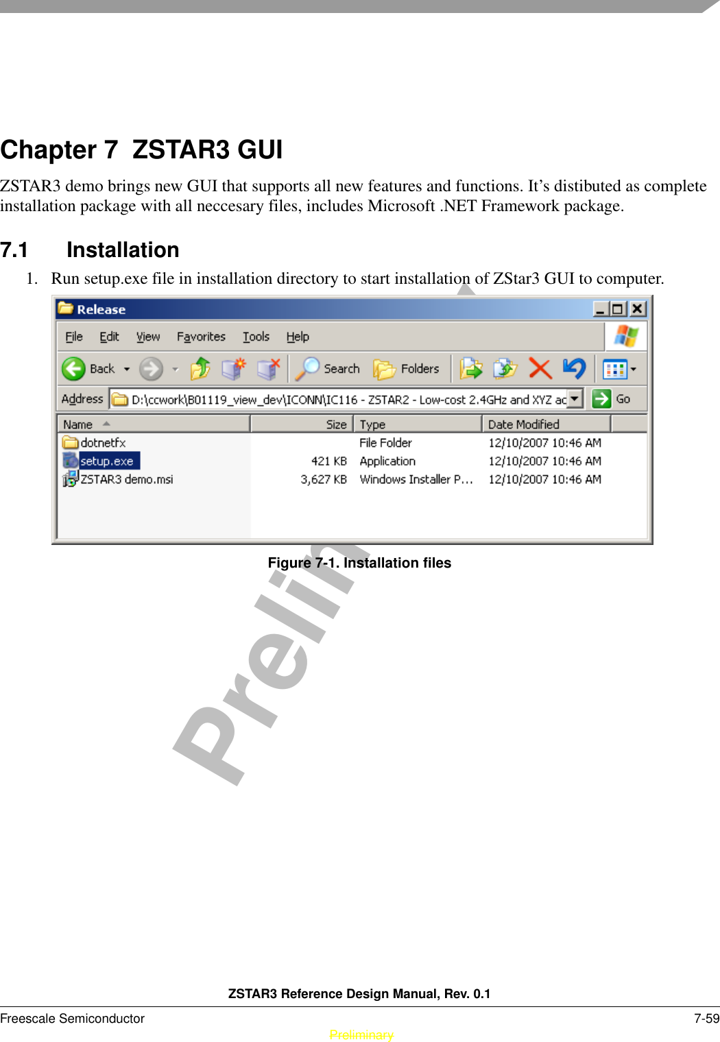
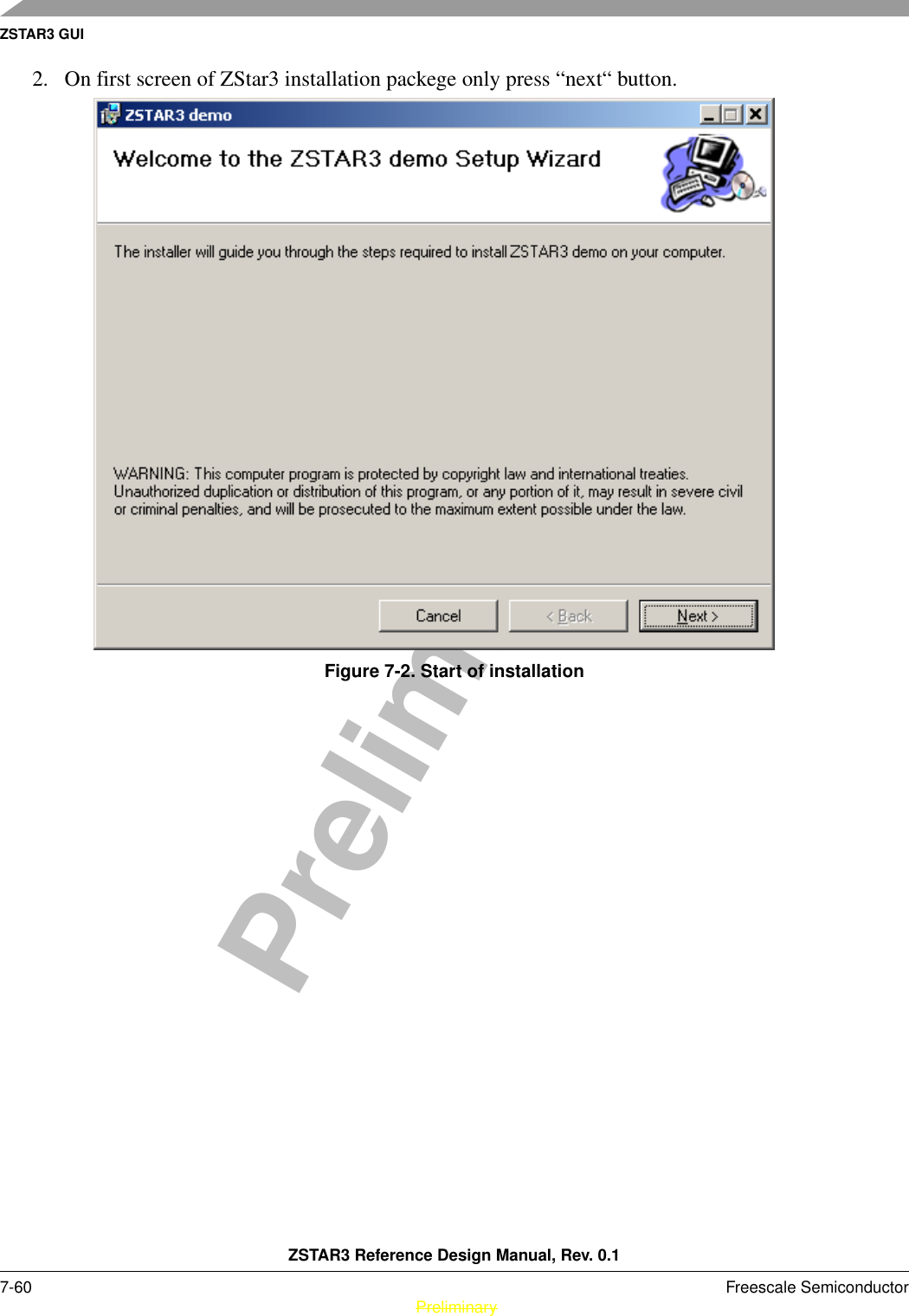
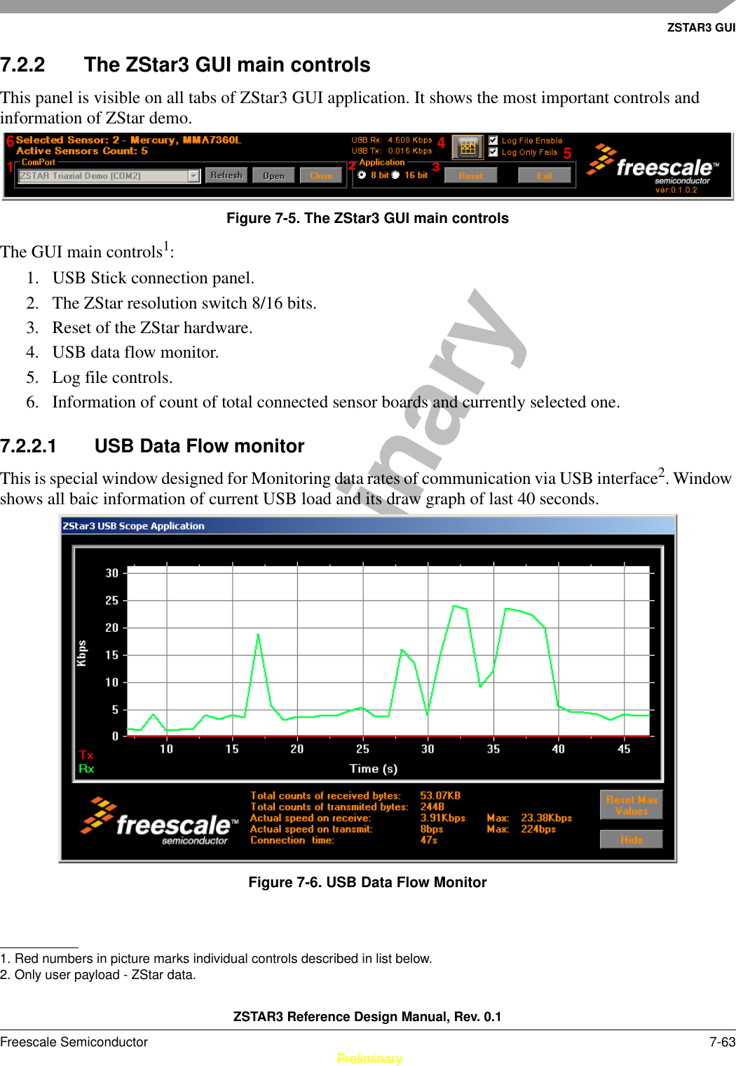
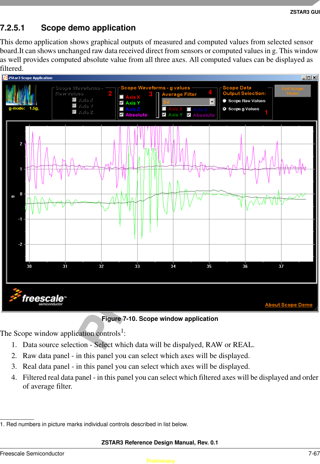
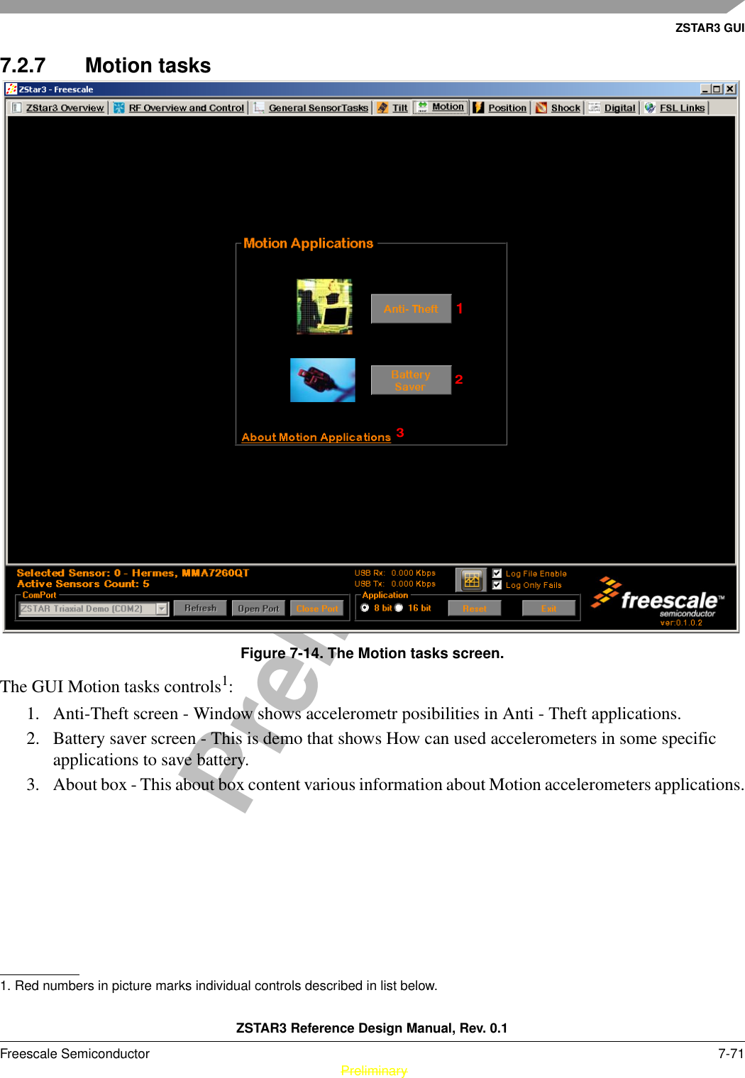
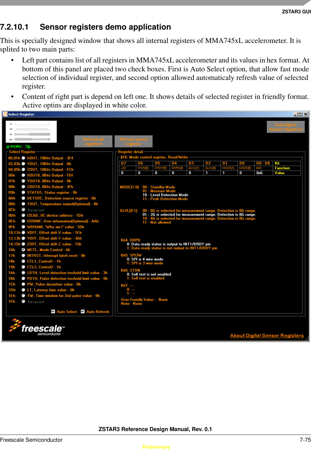
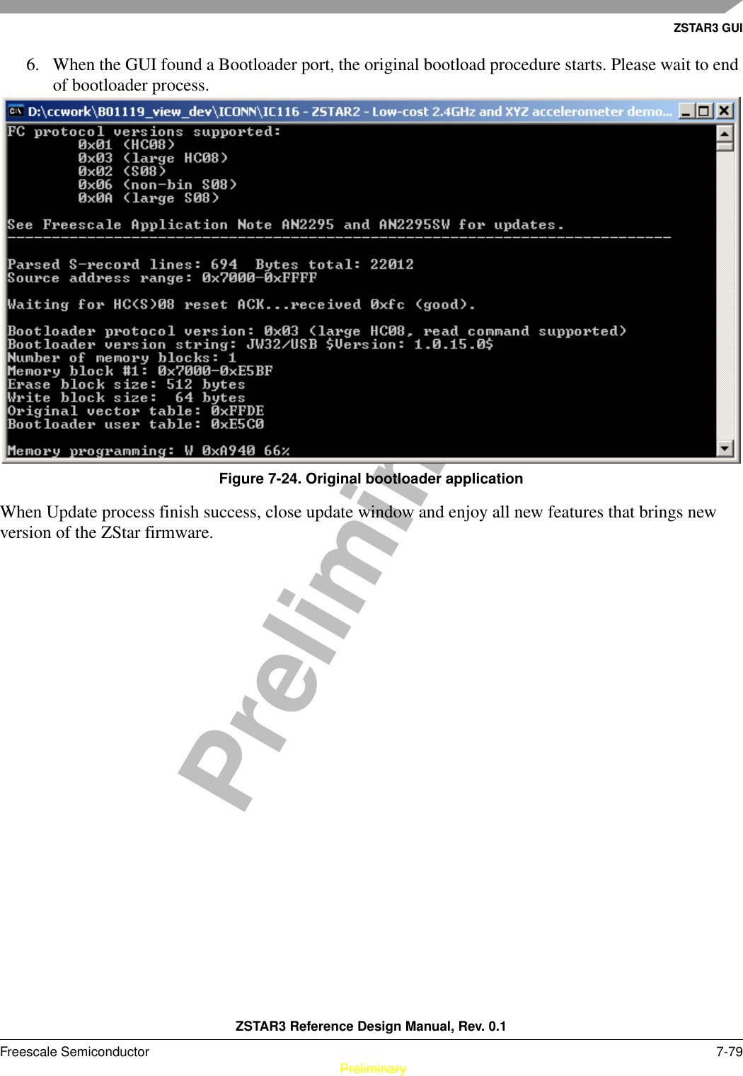
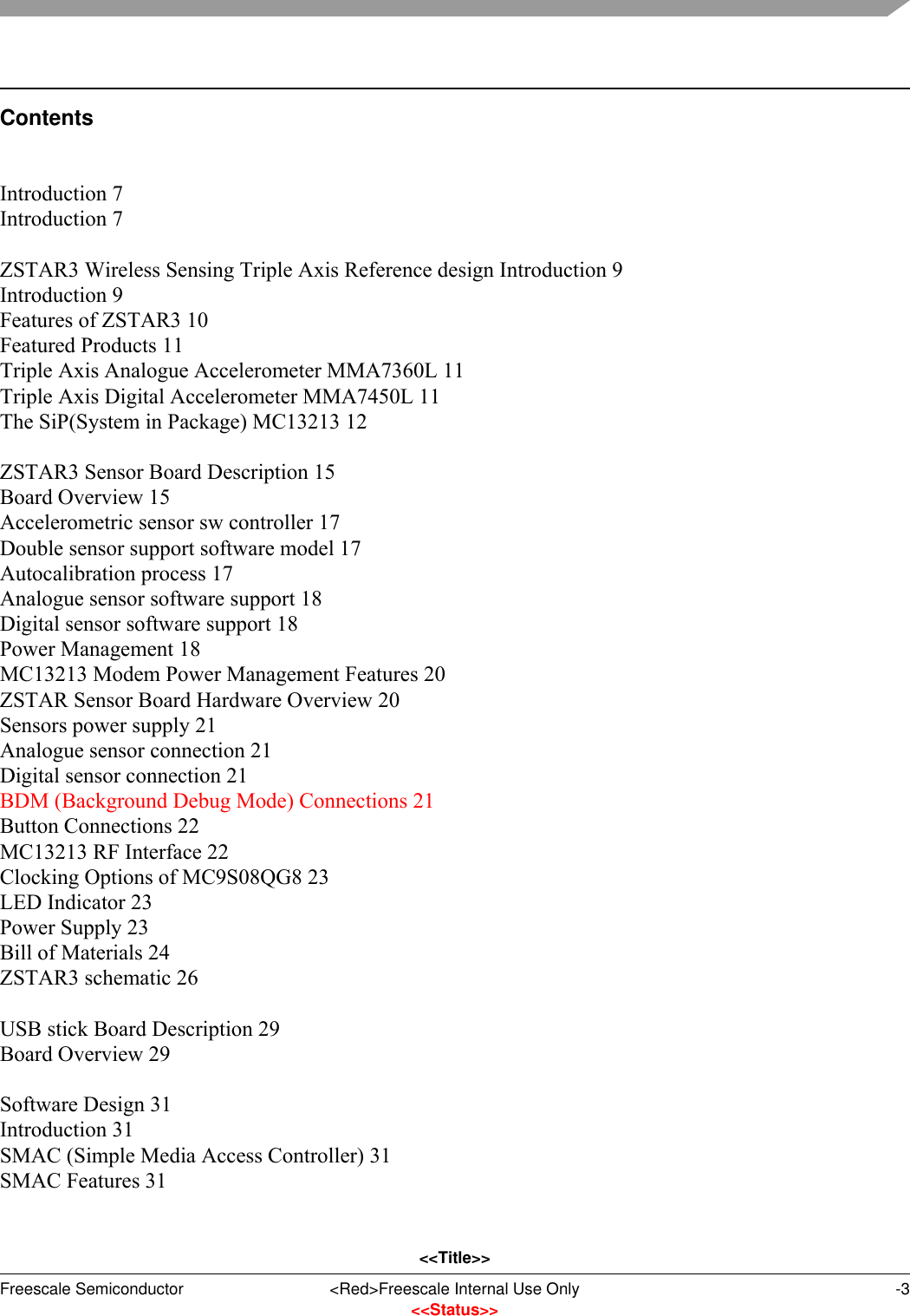
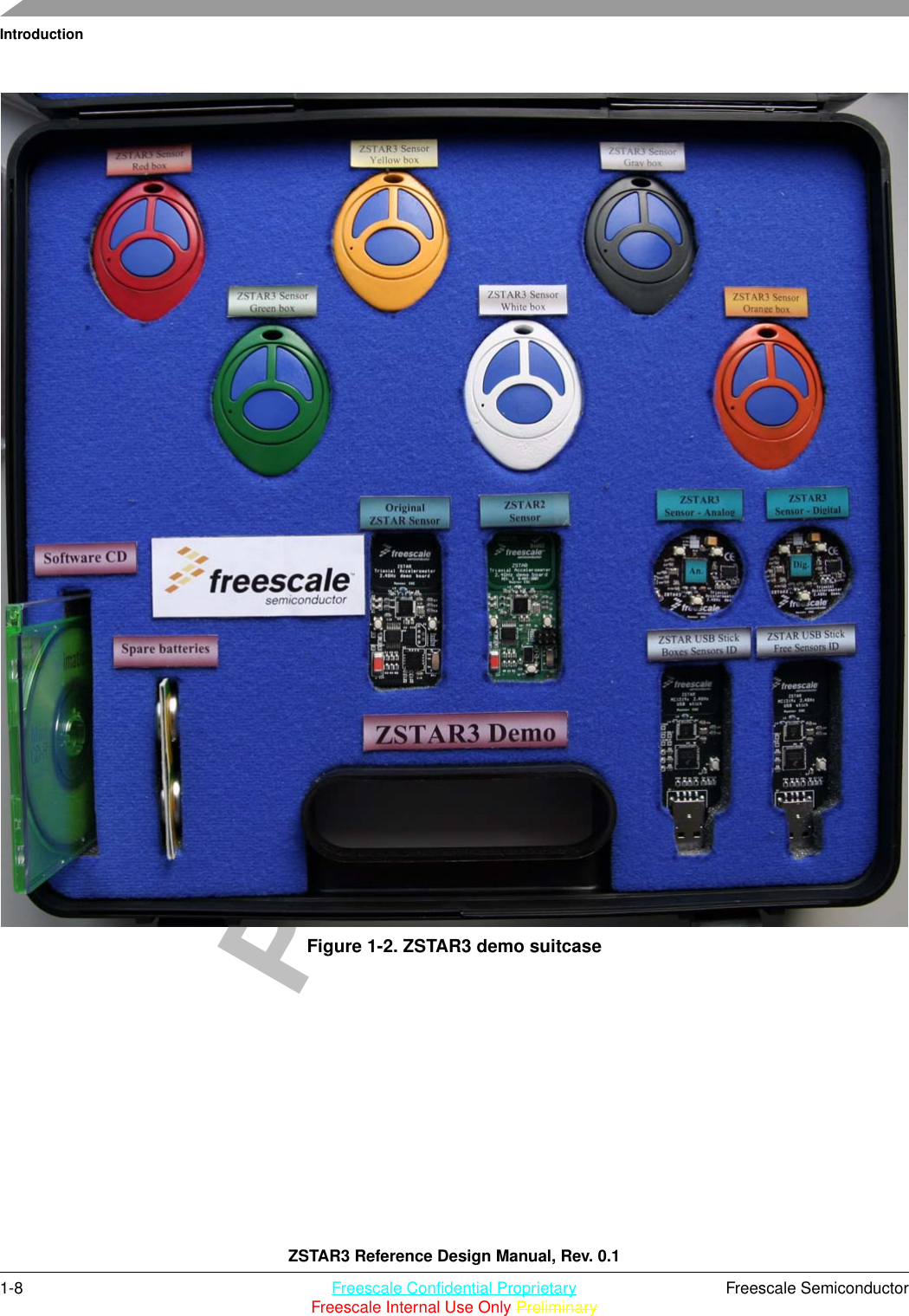
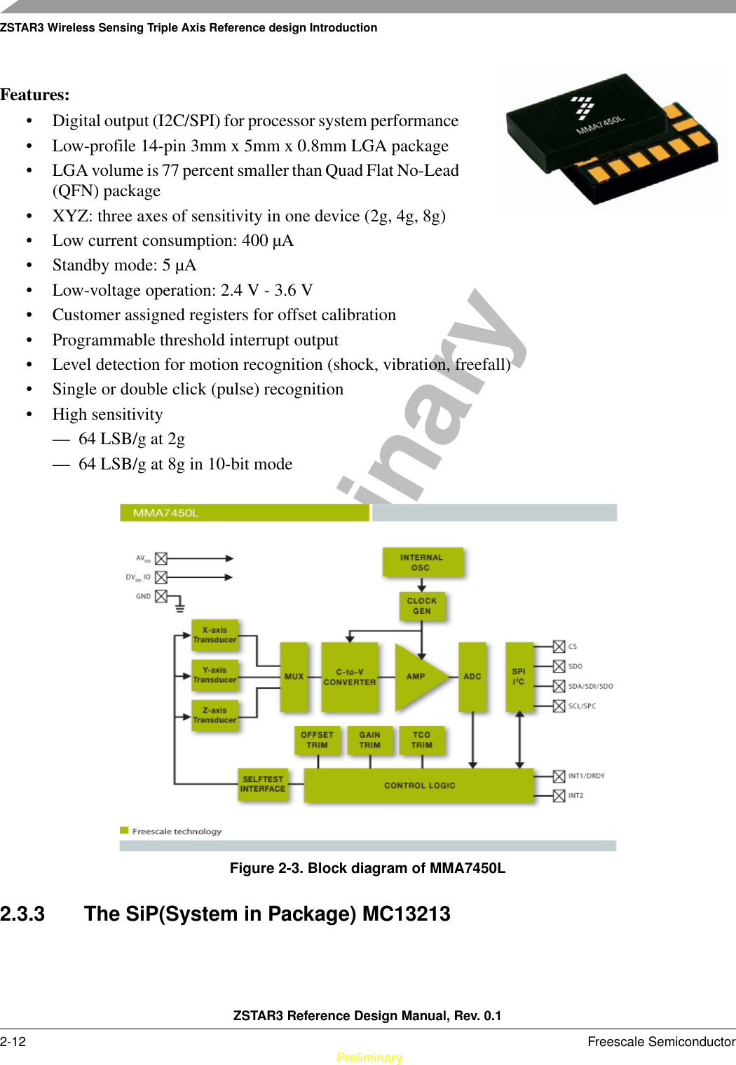
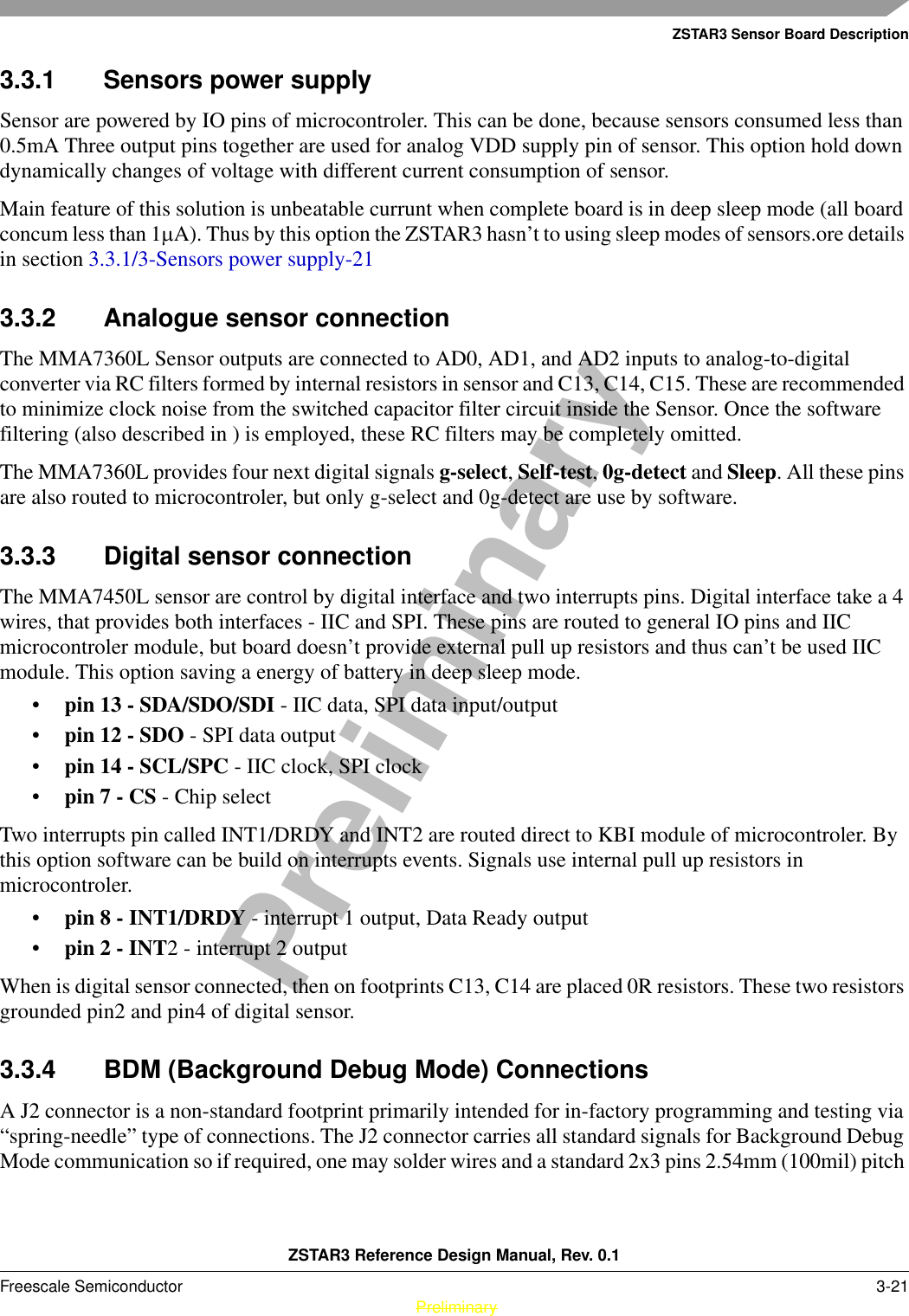
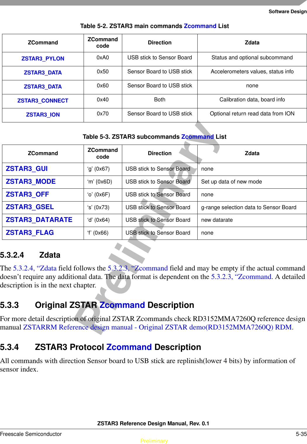
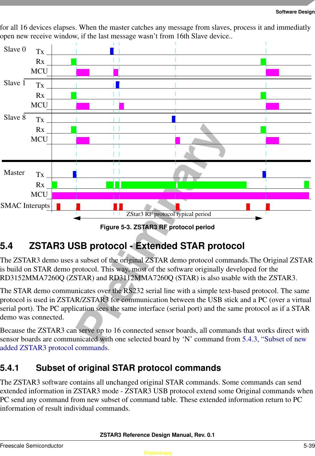
![Software DesignZSTAR3 Reference Design Manual, Rev. 0.15-46 Freescale Semiconductor PreliminaryPreliminary3. Now type: hc08sprg [bootloader com port number] [binary (S file) that you want to bootload], just like this:hc08sprg.exe com8 accelerometer_v2_ZSTARJW32-new-DUALBOOT.S194. Press ENTER and initial bootloader communication will start:](https://usermanual.wiki/Freescale-Semiconductor/ZT3/User-Guide-924065-Page-46.png)