Freescale Semiconductor ZT3 Zigbee Data Device User Manual ZSTAR3RM
Freescale Semiconductor, Inc. Zigbee Data Device ZSTAR3RM
Manual

freescale.com
ZStar3 Multiple Wireless Sensing Triple Axis
Reference Design
ZSTAR3RM
Rev. 0
01/2008
Safety of Radio Frequency Energy
The manufacturer has evaluated the transmitter for safe operation for uncontrolled use in
the general population. The measured power density at 1 cm is under the threshold
established by the FCC and is not required to be tested for specific absorption rate. The
manufacturer instructs the user that the transmitter should not be handled or placed near
the body continuously for more than 30 minutes while operating.
USA:
NOTE: This equipment has been tested and found to comply with the limits for a Class B
digital device, pursuant to Part 15 of the FCC Rules. These limits are designed to provide
reasonable protection against harmful interference in a residential installation. This
equipment generates, uses and can radiate radio frequency energy and, if not installed
and used in accordance with the instructions, may cause harmful interference to radio
communications. However, there is no guarantee that interference will not occur in a
particular installation. If this equipment does cause harmful interference to radio or
television reception, which can be determined by turning the equipment off and on, the
user is encouraged to try to correct the interference by one or more of the following
measures:
– Reorient or relocate the receiving antenna.
– Increase the separation between the equipment and receiver.
– Connect the equipment into an outlet on a circuit different from that to which the
receiver is connected.
– Consult the dealer or an experienced radio/TV technician for help.
This device complies with Part 15 of the FCC Rules. Operation is subject to the following
two conditions: (1) this device may not cause harmful interference, and (2) this device
must accept any interference received, including interference that may cause undesired
operation.
Changes or modifications not expressly approved by the party responsible for compliance
could void the user's authority to operate the equipment.
The antenna(s) used for this transmitter must not be co-located or operating in
conjunction with any other antenna or transmitter.
Canada:
This digital apparatus complies with Canadian ICES-003.
Cet appareil numérique est conforme à la norme NMB-003 du Canada.
Europe:
Compliant (CE)
Rev. 0
01/2008

<<Title>>
Freescale Semiconductor <Red>Freescale Internal Use Only -3
<<Status>>
Contents
Introduction 7
Introduction 7
ZSTAR3 Wireless Sensing Triple Axis Reference design Introduction 9
Introduction 9
Features of ZSTAR3 10
Featured Products 11
Triple Axis Analogue Accelerometer MMA7360L 11
Triple Axis Digital Accelerometer MMA7450L 11
The SiP(System in Package) MC13213 12
ZSTAR3 Sensor Board Description 15
Board Overview 15
Accelerometric sensor sw controller 17
Double sensor support software model 17
Autocalibration process 17
Analogue sensor software support 18
Digital sensor software support 18
Power Management 18
MC13213 Modem Power Management Features 20
ZSTAR Sensor Board Hardware Overview 20
Sensors power supply 21
Analogue sensor connection 21
Digital sensor connection 21
BDM (Background Debug Mode) Connections 21
Button Connections 22
MC13213 RF Interface 22
Clocking Options of MC9S08QG8 23
LED Indicator 23
Power Supply 23
Bill of Materials 24
ZSTAR3 schematic 26
USB stick Board Description 29
Board Overview 29
Software Design 31
Introduction 31
SMAC (Simple Media Access Controller) 31
SMAC Features 31

<<Title>>
-4 <Red>Freescale Internal Use Only Freescale Semiconductor
<<Status>>
Modifications of SMAC for ZSTAR3 RF protocol 31
New targets add to SMAC 32
New functions add to SMAC 32
ZSTAR3 RF Protocol 32
ZSTAR3 RF protocol features 32
Zpacket Format 33
Network Number(NetNum) 34
RX Strength 34
Zcommand 34
Zdata 35
Original ZSTAR Zcommand Description 35
ZSTAR3 Protocol Zcommand Description 35
ZSTAR3_PYLON 36
ZSTAR3_DATA 36
ZSTAR3_ACK 36
ZSTAR3_CONNECT 36
ZSTAR3_ION 36
ZSTAR3 Protocol SubCommands Description 36
ZSTAR3_GUI 36
ZSTAR3_MODE 37
ZSTAR3_OFF 37
ZSTAR3_GSEL 37
ZSTAR3_DATARATE 37
ZSTAR3_FLAG 37
ZSTAR3 RF Protocol description 37
Typical one period of ZSTAR3 RF protocol 38
ZSTAR3 USB protocol - Extended STAR protocol 39
Subset of original STAR protocol commands 39
Subset of original ZSTAR protocol commands 40
Subset of new added ZSTAR3 protocol commands 41
Burst mode 43
Network Lock feature of ZSTAR3 protocol 43
Semiautomatic Self-Calibration 43
Compatiblity with Original ZSTAR 44
Bootloader 44
Switch to Bootloader procedure 44
Bootloading Procedure 45
Triapplication software of USB Stick 48
CDC - Virtual Serial Port application 48
HID - Mouse application 48
HID - Keyboard application 48
Applications Switching 49
Application Setup 51
ZSTAR3 Installation Procedure 51

<<Title>>
Freescale Semiconductor <Red>Freescale Internal Use Only -5
<<Status>>
USB stick Installation 51
AN2295 Bootloader Drivers installation 55
ZSTAR3 GUI 59
Installation 59
ZSTAR3 GUI 62
Features of ZSTAR GUI 62
The ZStar3 GUI main controls 63
USB Data Flow monitor 63
Sensor Board overview screen 64
RF overview screen 65
General sensor tasks 66
Scope demo application 67
Acquire data demo application 68
Tilt tasks 69
Filtered tilt demo application 70
Motion tasks 71
Position tasks 72
Shock tasks 73
Digital tasks 74
Sensor registers demo application 75
Freescale Web Links. 76
The ZStar3 GUI Update USB Stick Software utility 76
Update process (Manual start) 77
References 81

<<Title>>
-6 <Red>Freescale Internal Use Only Freescale Semiconductor
<<Status>>
Introduction
ZSTAR3 Reference Design Manual, Rev. 0.1
Freescale Semiconductor Freescale Confidential Proprietary 1-7
Freescale Internal Use Only Preliminary
Preliminary
Chapter 1
Introduction
1.1 Introduction
This paper describes the next generation of design of a Wireless Sensing Triple Axis Reference design
(ZSTAR3), a demo for wireless demonstration of the 3-axes accelerometers MMA7450L
(RD3172MMA7450L) and MMA7360L (RD3172MMA7360L) sensors from Freescale. This demo is
succesor of previous Freescale demo ZSTAR and its fully compatible with it.Demois build on new
generation of Freescale parts and brings some extended functionalities.
The reference design will enable you to see how Freescale's accelerometers can add additional
functionality to applications in various industries. The accelerometer measurements can be grouped into 6
sensing functions - Fall, Tilt, Motion, Positioning, Shock and Vibration - for multifunctional applications.
The RD3172MMA7450L / RD3172MMA7360L development tool offers robust wireless communication
using the powerful, easy-to-use 2.4GHz frequency transceiver and microcontroller in one package
MC13213. Without any changes on board can be made with pin to pin compatibility allowing
implementation of the MC13214 for ZigBeeTM wireless applications.
Only Sensor board was updated completely, as receiver is still used USB stick from previous generation
of ZSTAR, but new software was developed that can support all new functionalities
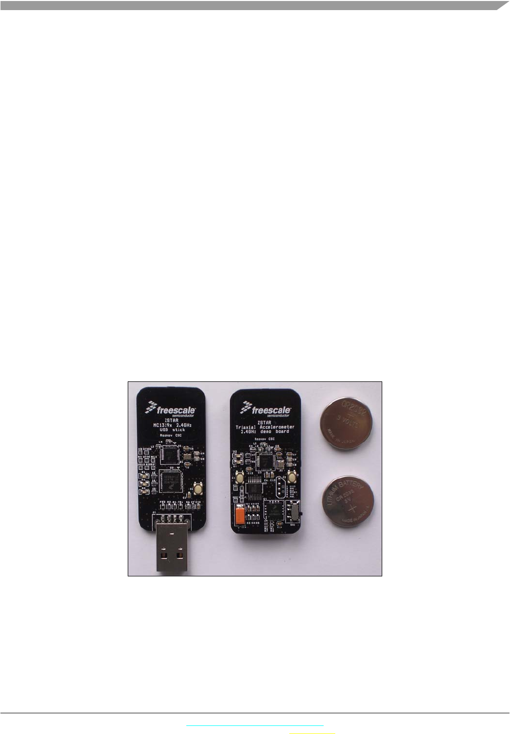
Figure 1-1. Original ZSTAR Demo photo (CR2032 batteries for comparison)
Introduction
ZSTAR3 Reference Design Manual, Rev. 0.1
1-8 Freescale Confidential Proprietary Freescale Semiconductor
Freescale Internal Use Only Preliminary
Preliminary
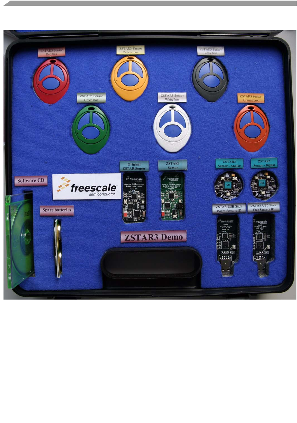
Figure 1-2. ZSTAR3 demo suitcase
ZSTAR3 Wireless Sensing Triple Axis Reference design Introduction
ZSTAR3 Reference Design Manual, Rev. 0.1
Freescale Semiconductor 2-9
Preliminary
Preliminary
Chapter 2
ZSTAR3 Wireless Sensing Triple Axis Reference design
Introduction
2.1 Introduction
The Wireless Sensing Triple Axis Reference design (ZSTAR3) has been designed as a new generation of
the previous ZSTAR (RD3152MMA7260Q) demo. A 2.4GHz radio-frequency (RF) link is also used in
this new demo and its based on new solution modem and microcontroler in one package MC13213
family.And it’s used for connection from the Sensor to PC, allowing the visualization of key accelerometer
applications as in previous demo.
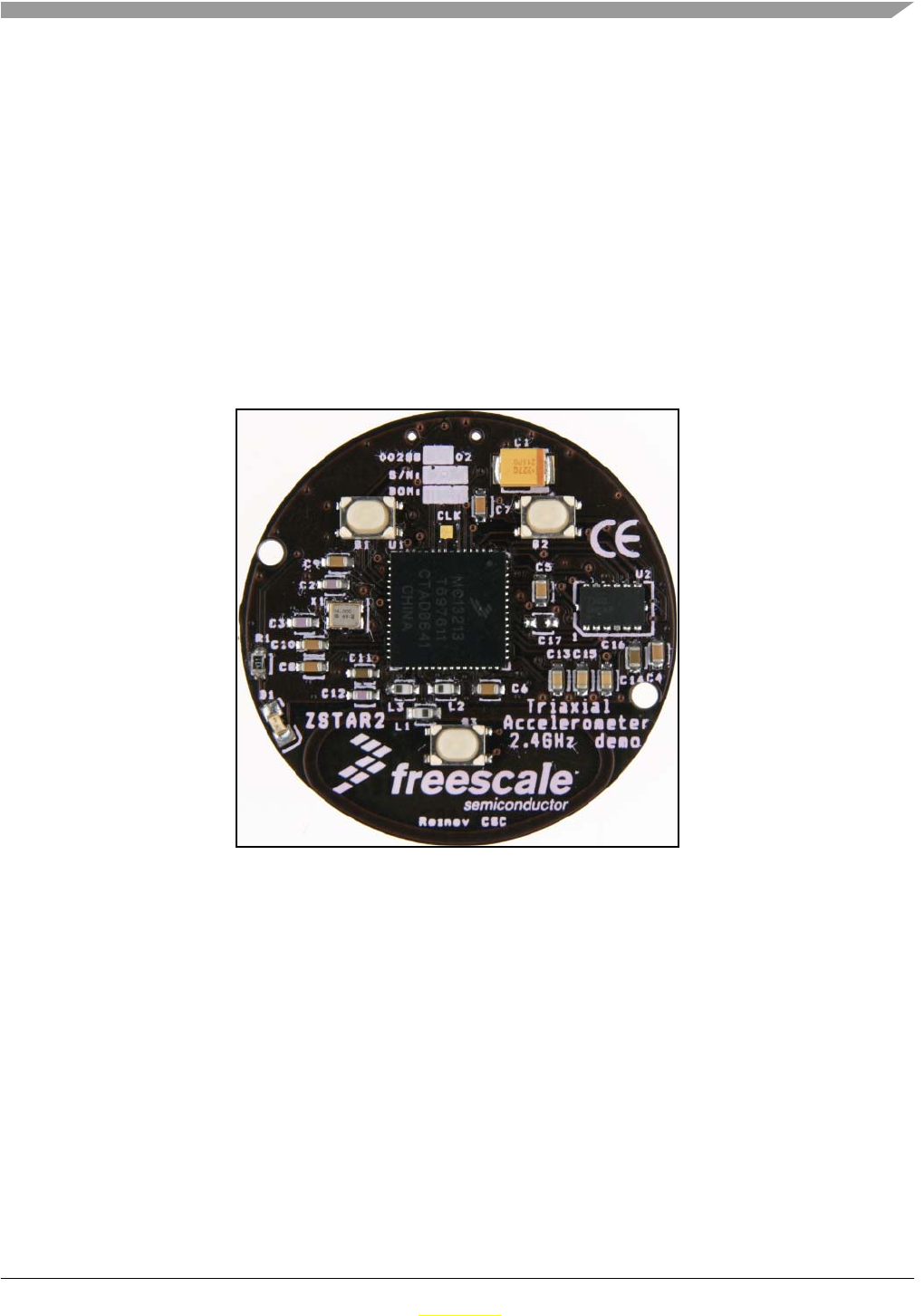
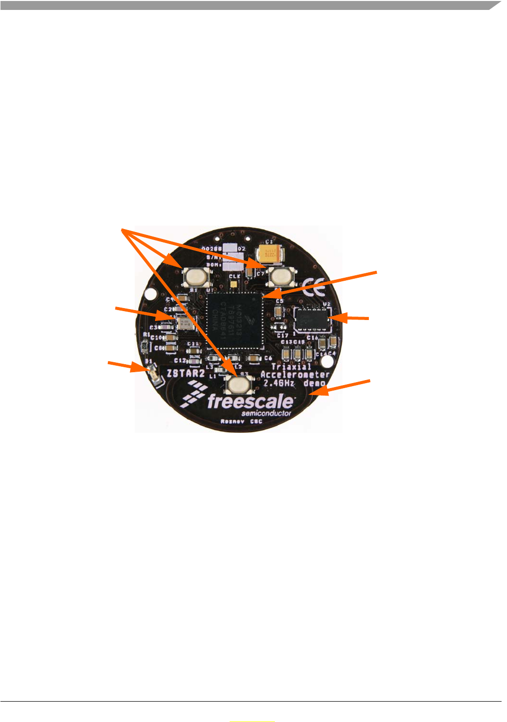
Figure 2-1. ZSTAR3 sensor board
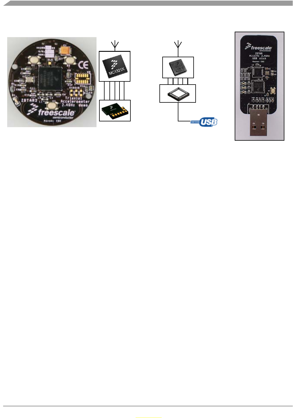
The demo consists of the two boards(new one and old one with new software):
• Sensor Board (or remote board) it is new board designed to demonstrating Freescale new 3-axes
accelerometers solution for digital(MMA7450L) and analogue(MMA7360L) sensing
accelerometric data and 2.4GHz RF modem with HCS08 microcontroler in one packege solution
as easy design for remote sensors.
• USB stick, with the MC13191 RF front-end, and the HC08 family MCHC908JW32 for the USB
communication. This board are used from older ZSTAR demo with new software.
Both sides communicate over the RF medium utilizing the freely available software lightly modified stack
SMAC from Freescale.
ZSTAR3 Wireless Sensing Triple Axis Reference design Introduction
ZSTAR3 Reference Design Manual, Rev. 0.1
2-10 Freescale Semiconductor
Preliminary
Preliminary
Figure 2-2. ZSTAR3 Block Diagram
2.2 Features of ZSTAR3
• Sensing of acceleration in 3 axes
• Handles digital and analogue sensors
• Wireless communication with sensors through the 2.4 GHz band
• RF protocol supports 16 sensors on one USB stick (receiver)
• STAR topology of RF network
• Data rate of a sensor is 30, 60 or 120 Hz
• Typical wireless range is 20 m, two walls or one floor
• Auto calibration function of the sensor
• USB communication on the receiver part
— Virtual serial port - interface for GUI and serial port terminal
— HID class - mouse for windows
— HID class – keyboard (game controller)
• 8-bit/16-bit working modes
• 3 push buttons on the sensor board
• Current consumption:
— in normal run mode: 1.8 - 3.9 mA, depends on the actual data rate
— in sleep mode: less than 900 nA
• Power consumption depends on the current output values of the sensor. At a standstill, the board
transmits only every 10th packet
• Sensor Board is powered by a coin-sized CR2032 3V battery
• Small size board fits a circular plastic box
MMA7360L
HC908JW32
MMA7450L
/
MC13213

ZSTAR3 Wireless Sensing Triple Axis Reference design Introduction
ZSTAR3 Reference Design Manual, Rev. 0.1
Freescale Semiconductor 2-11
Preliminary
Preliminary
2.3 Featured Products
This demo consists of several Freescale products whose main features are listed below. There are come up
two accelerometers, because the Sensor board can be assembled with digital or analogue Freescale
accelerometer.
2.3.1 Triple Axis Analogue Accelerometer MMA7360L
The MMA7360L is a low power, low profile capacitive micromachined accelerometer featuring signal
conditioning, a 1-pole low pass filter, temperature compensation, self test, 0g-detect which detects linear
freefall, and g-Select which allows for the selection between 2 sensitivities. Zero-g offset and sensitivity
are factory set and require no external devices. The MMA7360L includes a sleep mode that makes it ideal
for handheld battery powered electronics.
Features:
• 3mm x 5mm x 1.0mm LGA-14-pin package
• Low current consumption: 400 µA
• Sleep mode: 3 µA
• Low voltage operation: 2.2 V - 3.6 V
• High sensitivity (800 mV/g at 1.5g)
• Fast turn on time (0.5 ms enable response time)
• Self test for freefall detect diagnosis
• 0g-Detect for freefall protection
• Signal conditioning with low pass filter
• Robust design, high shocks survivability
• RoHS compliant
• Environmentally preferred product
• Low cost
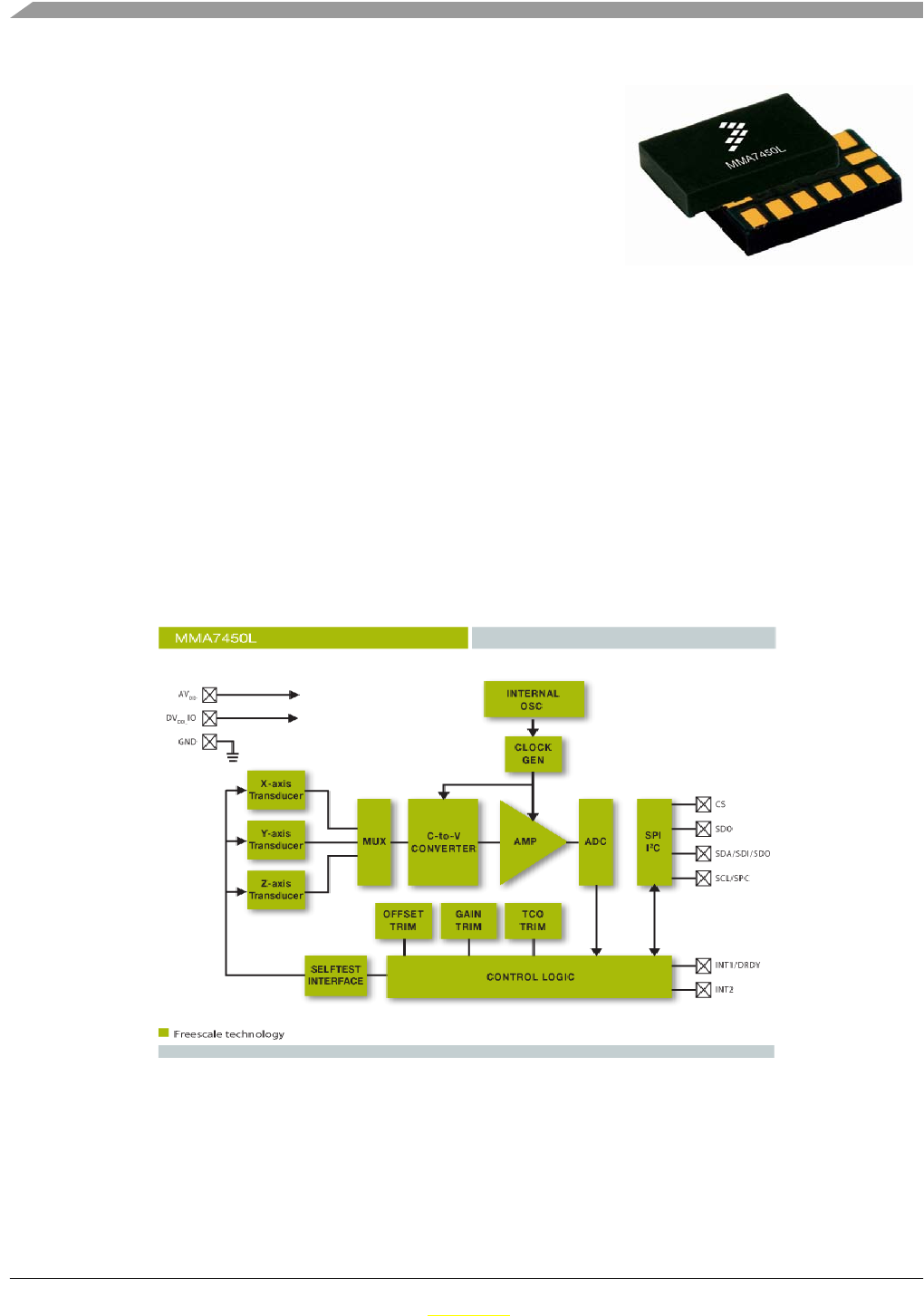
2.3.2 Triple Axis Digital Accelerometer MMA7450L
The MMA7450L is a digital output (I2C/SPI), low power, 3x5x0.8mm low profile package capacitive
micromachined accelerometer featuring signal conditioning, a low pass filter, temperature compensation,
self test, configurable to detect 0g through interrupt pins (INT1 or INT2), and pulse (click) detect for quick
motion detection. The 0g offset can be customer calibrated using assigned 0g registers and g-Select which
allows for command selection for 3 sensitivities (2g/4g/8g). Zero-g offset and sensitivity are factory set
and require no external devices. The MMA7450L includes a standby mode that makes it ideal for handheld
battery powered electronics.
ZSTAR3 Wireless Sensing Triple Axis Reference design Introduction
ZSTAR3 Reference Design Manual, Rev. 0.1
2-12 Freescale Semiconductor
Preliminary
Preliminary
Features:
• Digital output (I2C/SPI) for processor system performance
• Low-profile 14-pin 3mm x 5mm x 0.8mm LGA package
• LGA volume is 77 percent smaller than Quad Flat No-Lead
(QFN) package
• XYZ: three axes of sensitivity in one device (2g, 4g, 8g)
• Low current consumption: 400 µA
• Standby mode: 5 µA
• Low-voltage operation: 2.4 V - 3.6 V
• Customer assigned registers for offset calibration
• Programmable threshold interrupt output
• Level detection for motion recognition (shock, vibration, freefall)
• Single or double click (pulse) recognition
• High sensitivity
— 64 LSB/g at 2g
— 64 LSB/g at 8g in 10-bit mode
Figure 2-3. Block diagram of MMA7450L
2.3.3 The SiP(System in Package) MC13213

ZSTAR3 Wireless Sensing Triple Axis Reference design Introduction
ZSTAR3 Reference Design Manual, Rev. 0.1
Freescale Semiconductor 2-13
Preliminary
Preliminary
The MC13213 System in Package (SiP) integrates the MC9S08GT MCU with the MC1320x transceiver
into a single 9x9mm LGA package. The MC13213 provides 60 K Flash memory and 4 K of RAM. By
using the IEEE 802.15.4 Compliant MAC, or BeeStack ZigBee Protocol Stack, the MC13213 is an ideal
solution for sensing and control applications that require mesh networking.
Features:
• 40 MHz HCS08 low-voltage, low-power core
• 60 KB Flash and 4KB RAM memory
• Seven addressing modes for CPU
• Multiple 16-bit timers
• 2V to 3.4V operating voltage with on chip voltage
regulator
• -40 to +85 degrees C operating temperature
• Low external component count
• Requires a single 16 MHz crystal
• Programmable frequency clock output for MCU
• Auto-trim feature for crystal accuracy
• Eliminate need for external variable capacitors
• Allows for automated production frequency calibration
• 9x9x1 mm 71-pin LGA package
• RoHS compliant
• Up to 38 GPIO
• 8-bit port keyboard interrupt (KBI)
• 8-channel 10-bit analog-to-digital converter (ADC)
• Two independent serial communication interfaces (SCI) supporting up to 115.2 kBaud
• Inter-integrated circuit (I2C) with 100 kbps maximum bus loading
• Internal clock generator (ICG) at 100 kHz or 16 MHz (including internal reference generator)
• Low-voltage detection
• In-circuit debug and Flash programming available via on-chip background debug module (BDM)
• Programmable low voltage interrupt (LVI)
• Common on-chip processor (COP) watchdog timer
• Operates in the 2.4GHz band
• 250 kbps O-PQSK modulation
• 16 selectable channels
• 0 dBm nominal output power
• Programmable from -27 dBm to +3 dBm
• Receive sensitivity of -92 dBm (typical) at 1% PER
• Integrated transmit/receive switch

ZSTAR3 Wireless Sensing Triple Axis Reference design Introduction
ZSTAR3 Reference Design Manual, Rev. 0.1
2-14 Freescale Semiconductor
Preliminary
Preliminary
• Supports single-ended or full differential operation
• Supports external low-noise amplifier (LNA) and/or Power Amplifer (PA)
• Three lower power modes for increased power life
• Supports streaming and data processing modes
Software features:
•Simple MAC
— Small memory footprint (< 4 KB)
— Supports point-to-point and star network configurations
— ANSI C source code
• IEEE 802.15.4 compliant MAC
— Supports star, mesh and cluster tree topologies
— Supports beaconed and non-beaconed networks
— Supports guaranteed time slots (GTS) for predicable latency
— 128-bit Asymmetric Encryption Standard (AES)
— Object Code
• BeeStack ZigBee Protocol Stack
— ZigBee 2006 Complian Platform
— Object Code
ZSTAR3 Reference Design Manual, Rev. 0.1
Freescale Semiconductor 3-15
Preliminary
Preliminary
Chapter 3
ZSTAR3 Sensor Board Description
3.1 Board Overview
The Sensor Board utilizes a small footprint size dual-layer printed circuit board (PCB) containing all the
necessary circuitry for both accelerometer sensors and transferring data over a radio frequency (RF).
Figure 3-1. ZSTAR3 Sensor Board Overview
The board is powered by a Lithium coin-sized CR2032 battery. The block diagram of the board is as
follows:
Lithium battery on the opposite side
MC13213
MMA7450L /
LED indicator
PCB antennas
Buttons
MMA7360L
Crystal
ZSTAR3 Sensor Board Description
ZSTAR3 Reference Design Manual, Rev. 0.1
3-16 Freescale Semiconductor
Preliminary
Preliminary
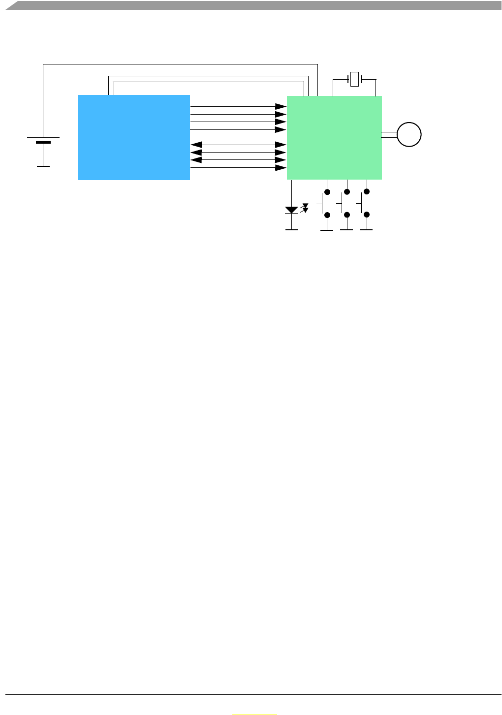
Figure 3-2. Sensor Board Block Diagram
Figure 3-3. - ZSTAR3 Sensor Board Software Overview shows in more detail, how different software
and hardware modules co-operate with each other. The main task of the Sensor Board is to:
• periodically wake-up from power saving mode
• measure all three XYZ acceleration values from the Sensor
• compose a data frame using simple ZSTAR3 RF Protocol
•use SMAC (Simple Media Access Controller) to send this data frame over the RF link
• go to sleep
This basic loop repeats roughly 30 times per second (period is 33.333ms) providing nearly a real-time
response from the Sensor.
MMA7450L
accelerometer
Power
MC13213
SIP - System in Antenna
CR2032
Lithium battery
package
MCU + RF
MMA7360LT
ZSTAR3 Sensor Board Description
ZSTAR3 Reference Design Manual, Rev. 0.1
Freescale Semiconductor 3-17
Preliminary
Preliminary
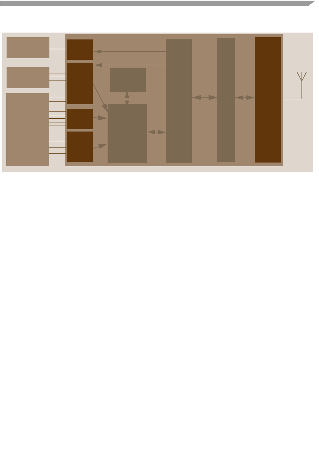
Figure 3-3. ZSTAR3 Sensor Board Software Overview
For the Sensor Board operation, several of the MC13213’s hardware modules are used: Analog to Digital
Converter (ADC), Synchronous Peripheral Interface (SPI), External Interrupt Request (IRQ), Keyboard
Interrupts and General Purpose Input/Output (GPIO).
3.2 Accelerometric sensor sw controller
Reading of XYZ levels and all others operation with sensor is depends on current assembled sensor. The
ZSTAR3 sensor board supports two types of Freescale accelerometric sensors, analogue(MMA736xLT)
and digital(MMA745xL). Assembly sensor is powered by IO pins of MCU, this solution allow reach a
lowest power consumtion in sleep mode.
3.2.1 Double sensor support software model
All common control functions of sensor are physically create as two individual function. First for analogue
and second for digital sensor. Main software is using only volatile pointers on this function, that are
assigned within initialization of program, by ” Recognise_Sensor() “ function. This function recognises an
assembled sensor and assigns right functions address to volatile RAM pointers. For example, by this way
analogue sensor is using ADC to read XYZ values of sensor and digital sensor is using digital interface,
but in source code are only one line:
p_Read_Accelerometer((void*) &(accel_data[0].x)).
3.2.2 Autocalibration process
The software uses for both types of sensor autocalibration process to get offset calibration values. It uses
a simple 0g X, 0g Y, +1g Z acceleration method. The sensor board runs autocalibration process for each g
scale of sensor, and thus uses for each g scale induvidual set of calibration values. For more details see
GPIO
ADC
KBI
Sensor
Buttons
GPIO
Sensor data
collector
Data
buffer RF
modem
2.4GHz
S
M
A
C
LED
RF
Protocol
Handler
and
driver

ZSTAR3 Sensor Board Description
ZSTAR3 Reference Design Manual, Rev. 0.1
3-18 Freescale Semiconductor
Preliminary
Preliminary
application note AN3447 - Implementing Auto-Zero Calibration Techniquefor accelerometers on
www.freescale.com.
3.2.3 Analogue sensor software support
The 3-axis accelerometer Sensor MMA7360L provides three separate analog levels for the X, Y and Z
axis. These outputs are ratiometric which means that the output offset voltage and sensitivity will scale
linearly with applied supply voltage. This is a key feature when interfacing to a microcontroller with A/D
converter reference levels tied to a power supply, because it provides system level cancellation of supply
induced errors in the analog to digital conversion process.
During the analog-to-digital conversion in the microcontroller, 10-bit resolution is used. MC13213 A/D
channels 0, 1 and 2 are connected to X (channel 1), Y (channel 2) and Z (channel 0) outputs of the
MMA7360L. The microcontroller’s APCTL1 register enables these ADC channels for pin I/O control by
the ADC module.
The ADCCFG register controls the selected mode of operation, clock source, clock divide, and
configuration for low power or long sample time.
The MMA7360L sensor has implemeted digital output of freefall detection module. This output is
connected direct to KBI(Keyboard interrupt module) and it’s used as default source of freefall detection.
3.2.4 Digital sensor software support
The MMA7450L provides a lots of various features, that almost are using by the ZSTAR3 demo. Complete
communication with sensor is done by digital interface. MMA7450L supports two standards of digital
comunication: SPI(Serial Peripherial Interface) and IIC(Inter-Integrated Circuit).
3.2.5 Power Management
A CR2032 Lithium battery provides a fairly limited charge for such a realtime-like demo that demands
frequent transmissions. Some sort of power management has to be implemented in order to keep the
current consumption at a reasonable level.
Typically, current consumptions of Sensor Board components are as follows:
• SIP - System in Pack MC13213
— 2.4GHz transceiver of MC13213
– in Off mode, 200nA
– in Hibernate mode, 2.3µA
– in Doze mode, 35µA
– in Idle mode, 500µA
– in Transmit mode, 30mA
– in Receive mode, 37mA
— 8-bit microcontroller of MC13213
ZSTAR3 Sensor Board Description
ZSTAR3 Reference Design Manual, Rev. 0.1
Freescale Semiconductor 3-19
Preliminary
Preliminary
– in Stop3 mode, 700nA
– in Wait mode, 560µA
– in Run mode, 6.5mA
• Triaxial accelerometers
— low-g triaxial analogue Sensor MMA7360L
– in Sleep mode, 3µA
– in Normal mode, 400µA
— low-g triaxial digital Sensor MMA7450L
– in Sleep mode, 5µA
– in Normal mode, 400µA
It is obvious that in a battery operated application care must be taken to ensure the lowest possible current
consumption, especially when the maximum current (provided by the battery) is somehow limited. A
CR2032 Lithium battery cannot provide current in the range of 40mA for long periods of time. To alleviate
high current surges, an additional large capacitor has been designed.
For transmission and reception using the MC13191, a specific scheme has been used to ensure the battery
is not depleted or overloaded. Targeting a 30 samples per second (33ms period) transmission rate. For
better power managment software using system of skiping transmission if sensor data are same or very
similar as in previous trasmit sample. Maximum count of skip trasmission is 10, then sensor data are
always transmitted and by this way is clear Timout timer in USB Stick. The ZSTAR3 typically open
receive window each 10th period (~333ms) to keep synchronization with USB Stick (Communication
Master) and for receive possible control data from master.
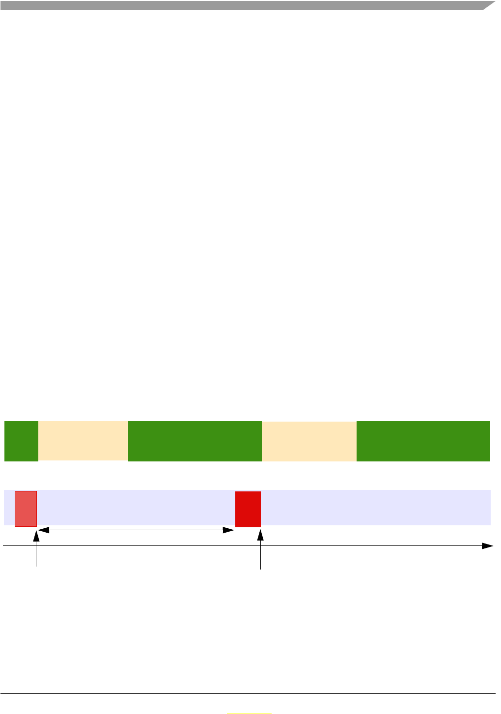
The following scheme for one transmission/sleep cycle is used for the typically data transfer:
Figure 3-4. Transmission/Sleep Cycle Details by basic 30Hz datarate
As shown on the previous diagram, all parts of the Sensor Board remain most of the time in
Sleep/Doze/Stop modes, in which the total current consumption is below 10µA.
time
Received Master
Doze
MC13213 RF MODEM:
Stop
MC13213 MCU:
Run Stop
Sensor
being
measured
TX
RX
NOT TO SCALE
Doze
data
transmitted
Pylon Message
Set up new message
and set RF modem
Run
Plan next RX window Stop
Trasmit time depends on sensor index

ZSTAR3 Sensor Board Description
ZSTAR3 Reference Design Manual, Rev. 0.1
3-20 Freescale Semiconductor
Preliminary
Preliminary
The current consumption of the transmitter is ~30mA at that time, but only for a short period of time
(typically ~600µs by 30Hz).
In order to keep the Sensor Board informed on the status of connection (for example, if the data-receiving
side - USB stick - is out of range, disconnected, etc.) and still synchronize with master, the reception has
to be turned on after the data has been transmitted. This is not really required within each loop cycle, and
in the actual implementation only on every 8th loop the receive window opens (receiver is enabled to
receive the acknowledgment). More in Section 5.3, “ZSTAR3 RF Protocol description.
The reception window is larger to fit any incoming receive data and the current consumption is also higher
during reception, so this portion of current consumption would be one of the largest if the acknowledgment
was received in every loop cycle.
The “optional receive” feature allows huge power savings, still keeping the reception of acknowledgment
data from the data-receiving side.
Some further savings might be incorporated by utilizing the timer-triggered transceiver events that are
described in the MC13213 Reference Manual.The MC13213, for example, latches a so-called time-stamp
of each received frame. The data-receiving side read this value and trigger the acknowledgment sent at
exactly specified time after reception (also, a start of data frame transmission can be programmed as
timer-triggered). The Sensor Board then narrow its own receive window to perfectly match the expected
time of the acknowledgment frame.
3.2.6 MC13213 Modem Power Management Features
MC13213 modem provides several power saving modes. One of them is called Doze mode in which the
MC13213 modem crystal oscillator remains active. An internal timer comparator is functional too,
providing a power efficient and accurately timed way of waking-up the application after a specified time.
This feature is fully utilized within the Sensor Board. The microcontroller calculates the time period for
which the application should be in power saving mode, then fills in the timer comparator registers in the
Modem, and the microcontroller goes into Stop mode (modem into Doze mode).
Once the timer reaches the pre-programmed time (a timer compare occurs), the modem’s IRQ signal is
asserted which brings the microcontroller out of the Stop mode. There are various scaling possibilities that
allow periods from a few µs up to 1073 seconds (~17 minutes) to be programmed, without intervention of
the microcontroller.
3.3 ZSTAR Sensor Board Hardware Overview
This section describes the Sensor Board in terms of hardware design. The MC13213 SIP drives only the
analogue or digital triaxial sensor. Because for analogue and digital sensor is used only one footprint, thus
has to be connected all necassary pins for both sensors and these connection has to be logical fit for both
sensors.

ZSTAR3 Sensor Board Description
ZSTAR3 Reference Design Manual, Rev. 0.1
Freescale Semiconductor 3-21
Preliminary
Preliminary
3.3.1 Sensors power supply
Sensor are powered by IO pins of microcontroler. This can be done, because sensors consumed less than
0.5mA Three output pins together are used for analog VDD supply pin of sensor. This option hold down
dynamically changes of voltage with different current consumption of sensor.
Main feature of this solution is unbeatable currunt when complete board is in deep sleep mode (all board
concum less than 1µA). Thus by this option the ZSTAR3 hasn’t to using sleep modes of sensors.ore details
in section 3.3.1/3-Sensors power supply-21
3.3.2 Analogue sensor connection
The MMA7360L Sensor outputs are connected to AD0, AD1, and AD2 inputs to analog-to-digital
converter via RC filters formed by internal resistors in sensor and C13, C14, C15. These are recommended
to minimize clock noise from the switched capacitor filter circuit inside the Sensor. Once the software
filtering (also described in ) is employed, these RC filters may be completely omitted.
The MMA7360L provides four next digital signals g-select, Self-test, 0g-detect and Sleep. All these pins
are also routed to microcontroler, but only g-select and 0g-detect are use by software.
3.3.3 Digital sensor connection
The MMA7450L sensor are control by digital interface and two interrupts pins. Digital interface take a 4
wires, that provides both interfaces - IIC and SPI. These pins are routed to general IO pins and IIC
microcontroler module, but board doesn’t provide external pull up resistors and thus can’t be used IIC
module. This option saving a energy of battery in deep sleep mode.
•pin 13 - SDA/SDO/SDI - IIC data, SPI data input/output
•pin 12 - SDO - SPI data output
•pin 14 - SCL/SPC - IIC clock, SPI clock
•pin 7 - CS - Chip select
Two interrupts pin called INT1/DRDY and INT2 are routed direct to KBI module of microcontroler. By
this option software can be build on interrupts events. Signals use internal pull up resistors in
microcontroler.
•pin 8 - INT1/DRDY - interrupt 1 output, Data Ready output
•pin 2 - INT2 - interrupt 2 output
When is digital sensor connected, then on footprints C13, C14 are placed 0R resistors. These two resistors
grounded pin2 and pin4 of digital sensor.
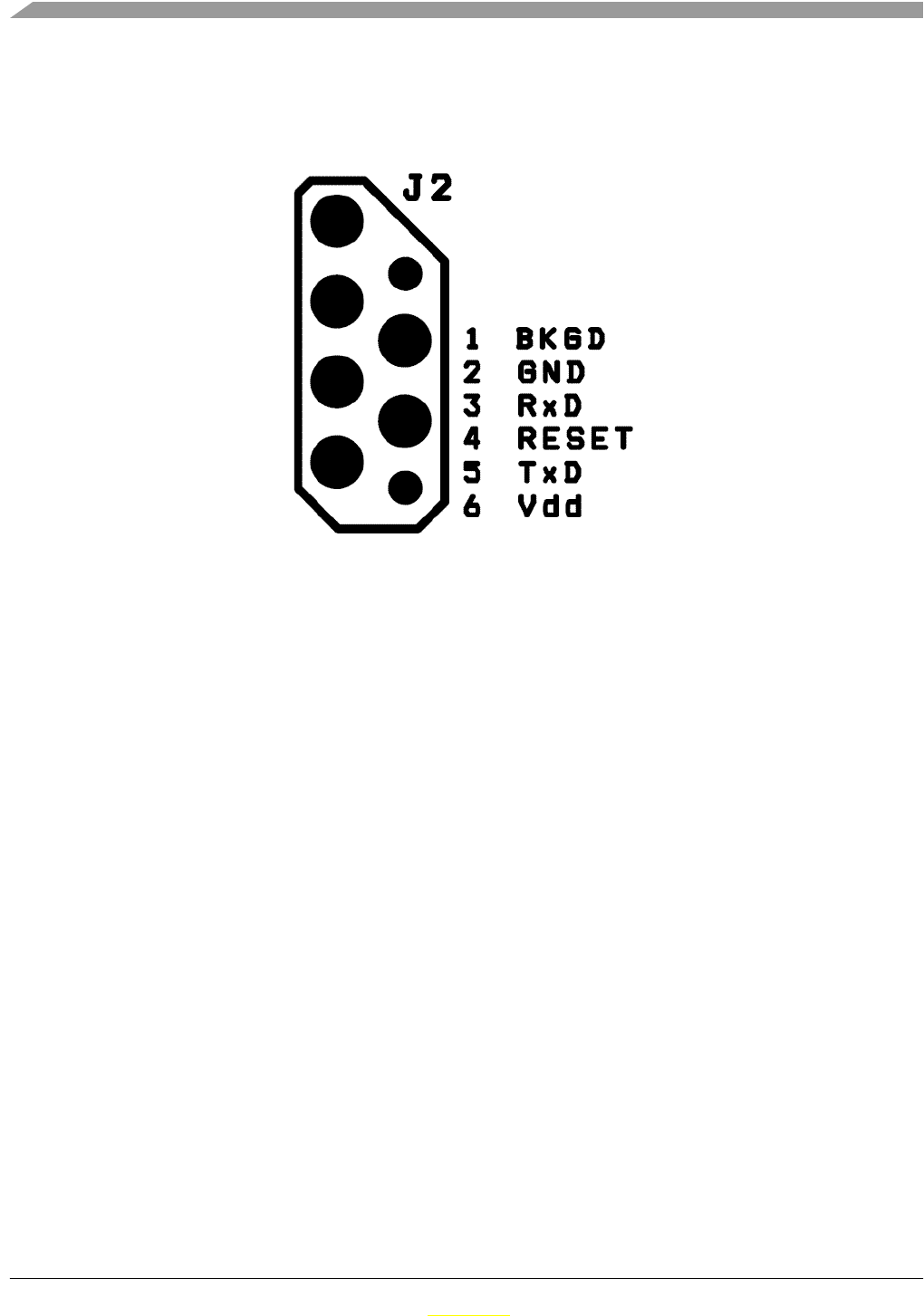
3.3.4 BDM (Background Debug Mode) Connections
A J2 connector is a non-standard footprint primarily intended for in-factory programming and testing via
“spring-needle” type of connections. The J2 connector carries all standard signals for Background Debug
Mode communication so if required, one may solder wires and a standard 2x3 pins 2.54mm (100mil) pitch
ZSTAR3 Sensor Board Description
ZSTAR3 Reference Design Manual, Rev. 0.1
3-22 Freescale Semiconductor
Preliminary
Preliminary
header for regular BDM re-programming. The pin numbering is shown on Figure 3-5. - BDM Connector
Layout
Figure 3-5. BDM Connector Layout
3.3.5 Button Connections
Three buttons (S1, S2 and S3) are connected directly to pins PTA0, PTA6 and PTA7. All have internal
pull-up resistors, and are part of the Keyboard Interrupt module, therefore allow a direct microcontroller
wake-up from the Stop modes.
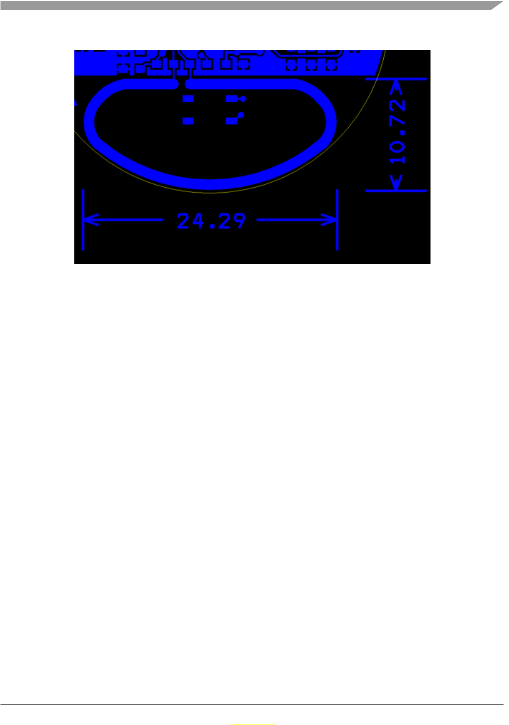
3.3.6 MC13213 RF Interface
The RF interface (antennas) were designed with the cost and board size in mind. Among several designs,
the PCB layout antennas were in the main consideration (cost). Of several PCB antenna designs available
for the 2.4GHz band (F-antenna, dipole, loop), the loop antenna has been selected mainly because of the
size required on the PCB.
The MC13213 transceiver provides a internal antenna switch of RF IN (receive) and PA OUT (transmit)
paths, thus can be use a simple loop antenna.
The antenna is designed as a “smile” layout , 10.7x24.3mm (420x960mils), made of 1.25mm (50mils)
wide trace of copper.
1
23
45
6
ZSTAR3 Sensor Board Description
ZSTAR3 Reference Design Manual, Rev. 0.1
Freescale Semiconductor 3-23
Preliminary
Preliminary
Figure 3-6. ZSTAR3 Antenna Layout
The matching is provided by L1 coil. L2 and L3 coils bias the transmitter output transistors to the CT_Bias
level.
The inductors used in this design are from TDK:
• L1 (3.3nH) MLG1608B3N3DT
• L2, L3 (22nH) MLG1608B22NJT
3.3.7 Clocking Options of MC9S08QG8
Due to the availability of accurate timing provided by the MC13213 internal transceiver, an internal
oscillator (ICG) in the MC13213 microcontroler is used as the main clock source for the microcontroller.
The protocol related timing is derived from RF modem timers, the microcontroller itself is clocked from
an internal oscillator. Microcontroler clock run with 20MHz on bus.
3.3.8 LED Indicator
On the design is used only a one LED, because the ZSTAR3 board is designed to fit a plastic box, that has
only a one position for light indicators. The LED is connected with current limiting serial resistor R1 direct
to PTC5 microcontroler pin.
3.3.9 Power Supply
The Sensor Board is powered by a Lithium coin-sized battery. The primary choice was the popular
CR2032.
A surface mounted SMTU series battery holder from RenataTM is placed on the underside of the PCB. The
SMTU series holders provide (by mechanical construction) battery reverse protection, so no additional
circuitry is required.

ZSTAR3 Sensor Board Description
ZSTAR3 Reference Design Manual, Rev. 0.1
3-24 Freescale Semiconductor
Preliminary
Preliminary
A large tantalum capacitor (C1, 220µF/4V) improves the response of the power supply to current peaks
caused by reception or transmission. Coin-sized Lithium CR2032 batteries are targeted at a maximum
continuous discharge current in the range of 3mA. Such a large capacitor helps to supply enough current
to the MC13213 during a receive/transmit without significant Vdd voltage drops.
Design doesn’t have any main power switch, thus switch on is done by pressing any button on board and
switch off is done by software (Timeout, Out of range, RF protocol command).
3.4 Bill of Materials
Table 3-1. Sensor Board Bill of Materials - Analog Sensor version
Item Quantity Reference Part Manufacturer Manufacturer order code
11 BATT1 battery holder
CR2032 Renata SMTU 2032-1
2 1 C1 220uF/4V AVX TAJB227M004R
3 3 C2, C3, C12 6.8pF TDK C1608CH1H070D
47 C4, C5, C6, C7,
C8, C9, C10 100nF TDK C1608JB1H104K
5 2 C11, C16 1uF TDK C1608JB1A105KB
6 3 C13, C14, C15 10nF TDK C1608CH1E103J
7 1 L1 3.3nH TDK MLG1608B3N3DT
8 2 L2, L3 22nH TDK MLG1608B22NJT
91 D1 Kingbright
KP-1608SEC Kingbright KP-1608SEC
10 1 J1 BDM + serial N/A
11 1 X1 16MHz NX2520SA NDK NX2520SA 16MHz EXS00A-02940
Specification n° EXS10B-07228
12 1 R1 150R TYCO RN73F1J150RBTG
13 3 S1, S2, S3 switch SKRP Alps SKRPADE010
(or SKRPACE010 or SKRPABE010)
14 1 U1 MC13213 Freescale MC13213
15 1 U2 MMA7360LT Freescale MMA7360LT
16 1 C17 NA NA NA

ZSTAR3 Sensor Board Description
ZSTAR3 Reference Design Manual, Rev. 0.1
Freescale Semiconductor 3-25
Preliminary
Preliminary
Table 3-2. Sensor Board Bill of Materials - Digital Sensor version
Item Quantity Reference Part Manufacturer Manufacturer order code
11 BATT1 battery holder
CR2032 Renata SMTU 2032-1
2 1 C1 220uF/4V AVX TAJB227M004R
3 3 C2, C3, C12 6.8pF TDK C1608CH1H070D
48 C4, C5, C6, C7,
C8, C9, C10, C17 100nF TDK C1608JB1H104K
5 2 C11, C16 1uF TDK C1608JB1A105KB
6 3 C13, C15 0R PHYCOMP 232270296001
7 1 L1 3.3nH TDK MLG1608B3N3DT
8 2 L2, L3 22nH TDK MLG1608B22NJT
91 D1 Kingbright
KP-1608SEC Kingbright KP-1608SEC
10 1 J1 BDM + serial N/A
11 1 X1 16MHz NX2520SA NDK NX2520SA 16MHz EXS00A-02940
Specification n° EXS10B-07228
12 1 R1 150R TYCO RN73F1J150RBTG
13 3 S1, S2, S3 switch SKRP Alps SKRPADE010
(or SKRPACE010 or SKRPABE010)
14 1 U1 MC13213 Freescale MC13213
15 1 U2 MMA7450L Freescale MMA7450L
16 1 C14 NA NA NA
ZSTAR3 Sensor Board Description
ZSTAR3 Reference Design Manual, Rev. 0.1
3-26 Freescale Semiconductor
Preliminary
Preliminary
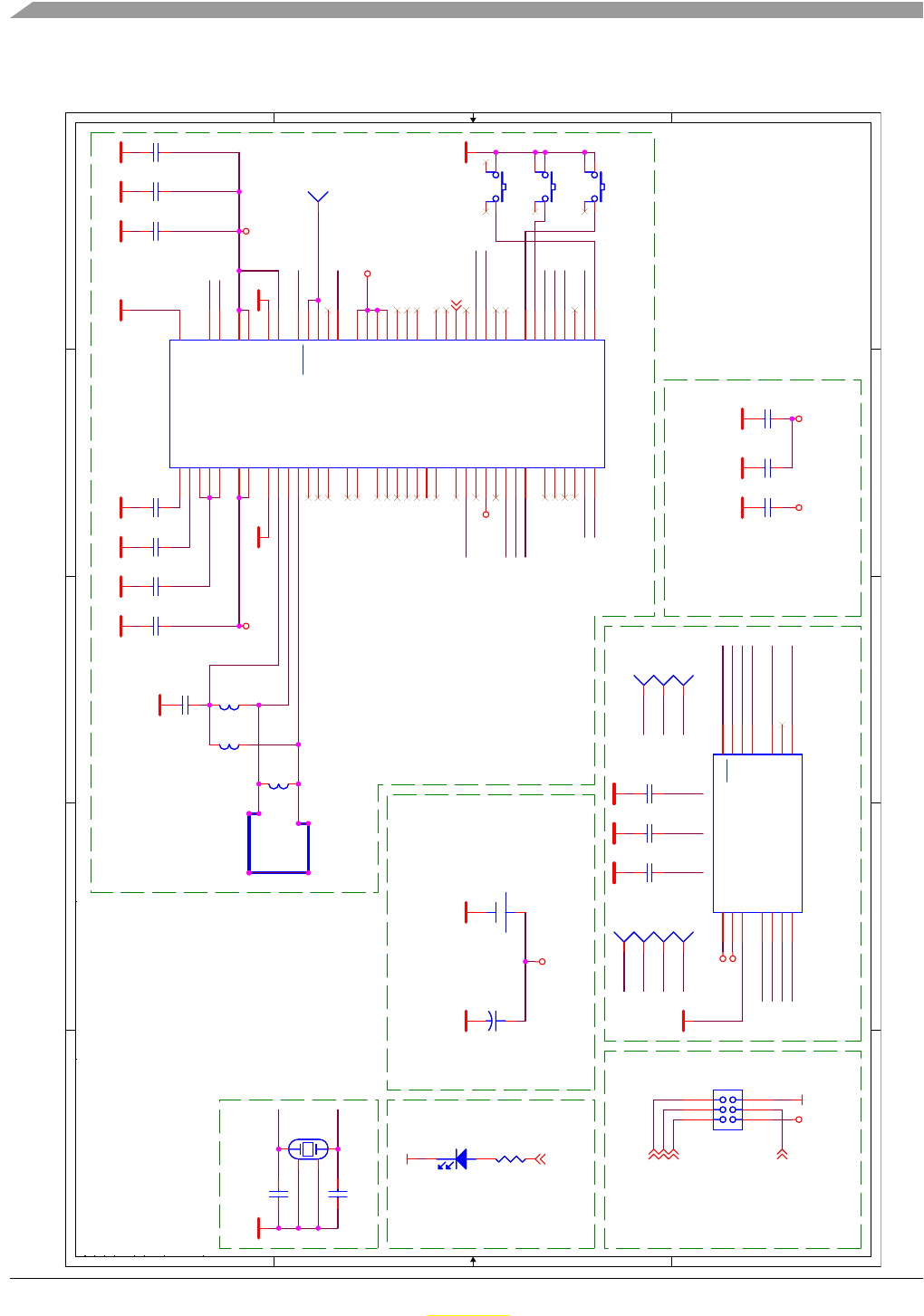
3.5 ZSTAR3 schematic
5
5
4
4
3
3
2
2
1
1
D D
C C
B B
A A
XTAL2
XTAL1
Antenna
XTAL1
XTAL2
RESET
TXD
RXD
BDM
Z-axis
Y-axis
X-axis
SLEEP
X-axis
Y-axis
Z-axis
X-axis
0g_detect
self_test
g-select
SLEEP
self_test
INT1
SDO
SCL/SPC
SCL/SPC
Y-axis
Z-axis
switch1
SDO
switch3
switch2
INT1
0g_detect
g-select
SDO
self_test
SCL/SPC 0g_detect
INT1
SLEEP
GND
GNDGND
GND
GNDGND GND GND
VDDVDD
GND
GND
GND GND GND
GND
GND VDD
VDD_mcu
GND
GND
GND GND GND
GND
VDD
GND
GND
VDD_mcu
GND
DVdd_mcu
GND
DVdd_mcuVDD_mcu
DVdd_mcu
RXD
TXD
RESET
BDM
LED1
LED1
Title
Size
Design Name:
Rev
Modify Date: Sheet of
Schematic Name:
Copyright Freescale
POPI Status:
Author:
0
ZSTAR3
Freescale Semiconductor Roznov CSC
1. maje 1009
756 61 Roznov p.R., Czech Republic, Europe
A4
11
Friday, November 16, 2007
SCHEMATIC1
General Business Information
Petr Gargulak
2005
D:\CCWORK\B01119_VIEW_DEV\ICONN\IC116 - ZSTAR2 - LOW-COST 2.4GHZ AND
X
BDMSENSOR
LED
MCU + RF
POWER SOURCE
CLOCK SOURCE
SENSOR SOURCE CAPACITORS
SDASDA 1
SCLSCL 1INT2INT2 1
C4
100nF
C4
100nF
C16
1uF
C16
1uF
BATT1
Battery/Renata CR2032
BATT1
Battery/Renata CR2032
R1
150R
R1
150R
C13
10nF
C13
10nF
J1
BDM
J1
BDM
1 2
3 4
65
L1
3.3nH
L1
3.3nH
D1
LED
D1
LED
C2 6.8PFC2 6.8PF
MCU_CLKMCU_CLK 1
C12
6.8PF
C12
6.8PF
C5
100nF
C5
100nF
L3
22nH
L3
22nH
C3 6.8PFC3 6.8PF
INT1INT1 1
GNDGND 1
S2
Alps SKRP
S2
Alps SKRP
1 3
42
C15
10nF
C15
10nF
C14
10nF
C14
10nF
L2
22nH
L2
22nH
C11
1uF
C11
1uF
+C1
220uF/4V
+C1
220uF/4V
12
C7
100nF
C7
100nF
C10
100nF
C10
100nF
X1
16MHz NX2520SA
X1
16MHz NX2520SA
12
3
4
U2
MERCURY/ION
U2
MERCURY/ION
VDD,AVdd 6
VSS,GND 5
Xout,GND 2
Yout,NC 3
Zout,Addr0 4
0g - detect,INT2 9
Self_test,SDA/SDI/SDO
13
g-select, NC
10
Sleep, CS
7NC, DVdd_IO 1
NC, INT1/DRDY
8NC, NC
11
NC, SDO
12
NC,SCL/SPC
14
C6
100nF
C6
100nF
C9
100nF
C9
100nF
S1
Alps SKRP
S1
Alps SKRP
1 3
42
C8
100nF
C8
100nF
S3
Alps SKRP
S3
Alps SKRP
1 3
42
SDOSDO 1
U1
MC13211
U1
MC13211
PTE0/TxD1 20
PTA3/KBD3
1
VREFH
60
VREFL
61
PTA0/KBD0
62
PTA1/KBD1
63
PTA2/KBD2
64
PTC6
18
PTC7
19
PTE1/RxD1 21
PTA4/KBD4
2
PTA5/KBD5
3
PTA6/KBD6
4
PTA7/KBD7
5
VDDAD
6
CLKOo
10
PTG0/BKGD/MS
7
PTG1/XTAL
8
PTG2/EXTAL
9
RESET
11
PTC0/TxD2
12
PTC1/RxD2
13
PTC2/SDA
14
PTC3/SCL
15
PTC4
16
PTC5
17
XTAL2
28
VDDLO2 29
VDDLO1 30
VDDVCO 31
VBATT 32
VDDA 33
CT_Bias 34
RFIN_M 35
PTB0/AD0 52
PTB1/AD1 53
PTB2/AD2 54
PTB3/AD3 55
PTB4/AD4 56
PTB5/AD5 57
PTB6/AD6 58
PTB7/AD7 59
GPIO1 44
VDD
45
ATNBi 46
PTD2
47
PTD4
48
PTD5
49
PTD6
50
PTD7
51
RFIN_P 36
TINJ_M 37
PAO_P 38
PAO_M 39
SM 40
GPIO4 41
GPIO3 42
GPIO2 43
GPIO5 24
GPIO6 25
GPIO7 26
XTAL1
27
VDDINT 23
VDDD 22
PTE5/SPICLK 65
PTE4/MOSIi 66
PTE3/MISOo 67
PTE2/CEBi 68
IRQ/IRQo 69
PTD1/RXTXENi
70
PTD3/RSTBi
71
Exposed Pad
72
C17
100nF
C17
100nF
CSCS 1

ZSTAR3 Sensor Board Description
ZSTAR3 Reference Design Manual, Rev. 0.1
Freescale Semiconductor 3-27
Preliminary
Preliminary

ZSTAR3 Sensor Board Description
ZSTAR3 Reference Design Manual, Rev. 0.1
3-28 Freescale Semiconductor
Preliminary
Preliminary
ZSTAR3 Reference Design Manual, Rev. 0.1
Freescale Semiconductor 4-29
Preliminary
Preliminary
Chapter 4
USB stick Board Description
4.1 Board Overview
The USB Stick board is used same as in original ZSTAR demo with new software. For more hardware
details please check RD3152MMA7260 Reference Design manual on www.freescale.com
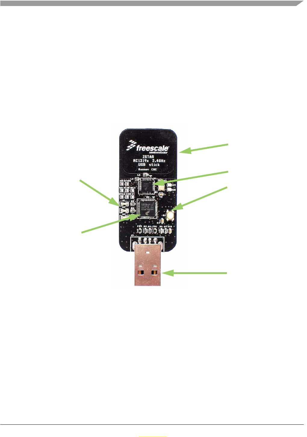
Figure 4-1. USB stick Board Overview
MC13191
MCHC908JW32
LED indicators
PCB antennas
USB “A” type plug
Button
USB stick Board Description
ZSTAR3 Reference Design Manual, Rev. 0.1
4-30 Freescale Semiconductor
Preliminary
Preliminary
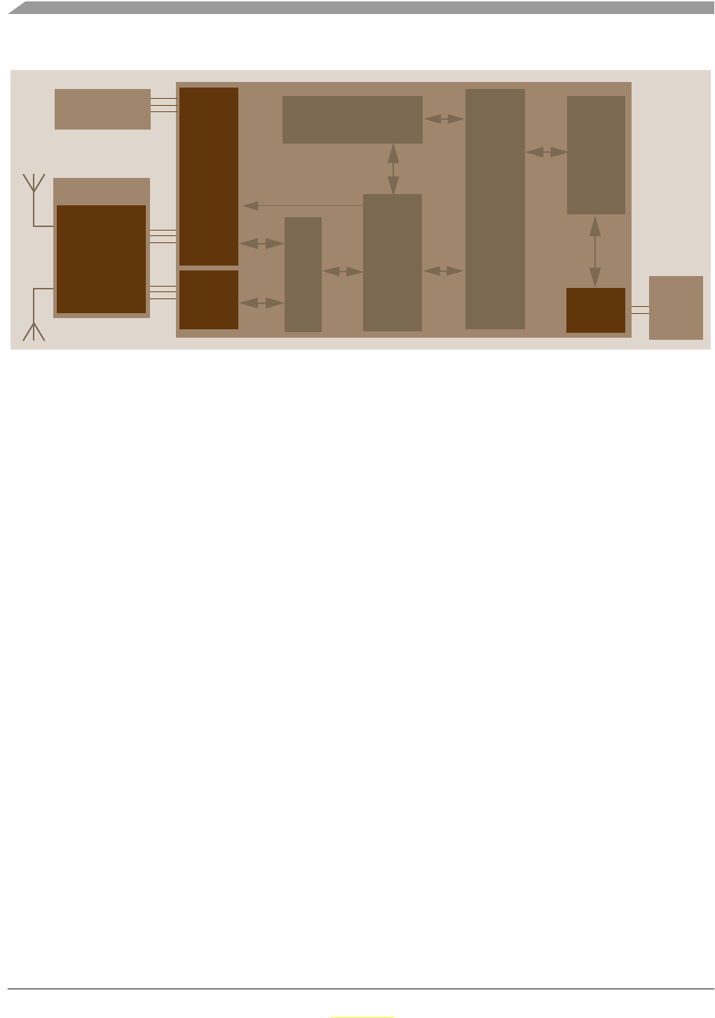
Figure 4-2. USB Stick software overview
Figure 4-2. USB Stick software overview shows, in more detail, how different software and hardware
modules co-operate with each other. There are two main tasks of the USB stick board:
• receive the data from the MC13191 transceiver and store it in RAM buffer
• handle the USB module communication, decode and provide the data from the RAM buffer
These two are somewhat independent and the only common point between them is the accelerometer and
button data buffer in RAM. The RF software communicates with the Sensor Board and retrieves the latest
accelerometer data. This is stored in RAM and can be independently read by the PC application via the
USB link. The protocol employed on the PC side is just a subset of the Original ZSTAR that is build on
simple STAR protocol used in the original RD3112MMA7260Q demo. The protocol is described in
section Section 5.4, “ZSTAR3 USB protocol - Extended STAR protocol.
For the USB stick board operation, several MCHC908JW32 hardware modules are used: USB 2.0
Full-speed (USB), Synchronous Peripheral Interface (SPI), Keyboard Interrupt (KBI) and a General
Purpose Input/Output (GPIO).
GPIO
SPI USB
RF
Protocol
Handler
LEDs
MC13191
RF modem
2.4 GHz
S
M
A
C
PC
Protocol
Handler
Sensors Data
USB
driver
USB
port

ZSTAR3 Reference Design Manual, Rev. 0.1
Freescale Semiconductor 5-31
Preliminary
Preliminary
Chapter 5
Software Design
5.1 Introduction
This section describes the design of the ZSTAR3 software blocks. The software description comprises
these topics:
•5.2, “SMAC (Simple Media Access Controller) modifications description
•‘Air’ 5.3, “ZSTAR3 RF Protocol protocol description
•Serial 5.4, “ZSTAR3 USB protocol - Extended STAR protocol description
• AN2295 5.6, “Bootloader (over USB) implementation notes
5.2 SMAC (Simple Media Access Controller)
The SMAC is a simple ANSI C based code stack available as sample source code which can be used to
develop proprietary RF transceiver applications using the MC1319x, MC1321x.
5.2.1 SMAC Features
• Compact footprint:
— 2K FLASH
— 10 bytes (+ maximum packet length) RAM
— As low as 16kHz bus clock
• Can be used to demonstrate coin cell operation for a remote control
• MC1319x/MC1321x compatible
• Very-low power, proprietary, bi-directional RF communication link
• ANSI C source code targeted at the HCS08 core and portable to almost any CPU core (including
4-bit)
• Low priority IRQ
• Sample application included, extremely easy to use
• Liberally commented
5.2.2 Modifications of SMAC for ZSTAR3 RF protocol
The development of the ZSTAR software is based on the free SMAC stack available from Freescale. The
SMAC version used was 4.2. To SMAC has been added a three new targets files for Original USB Stick /
Sensor and for new ZSTAR3 sensor board. Furthermore was add a couple of new function to this SMAC.

Software Design
ZSTAR3 Reference Design Manual, Rev. 0.1
5-32 Freescale Semiconductor
Preliminary
Preliminary
A fully detailed description of the SMAC is in the SMAC Reference Manual (SMACRM.pdf), available
together with SMAC source code.
5.2.2.1 New targets add to SMAC
Modification of SMAC for individual application are done by targets files that exact defines all pins and
peripheries. For ZSTAR3 project purposes has been added to SMAC three new targets:
• MC1319XZSTAR_USB.c/h - these files describes Original ZSTAR USB Stick board
• ZSTAR_SENSOR.c/h - these files describes Original ZSTAR and ZSTAR3 Sensor board
• MC1321XZSTAR2.c/h - these files describes ZSTAR3 Sensor board
5.2.2.2 New functions add to SMAC
Original SMAC doesn’t has implemented any advanced transceiver time operations as for example delayed
trasmit / receive and others. On these functionalities is based ZSTAR3 RF protocol and thus had to be
implemented. List of new functions in SMAC mac layer:
• UINT32 MLMEGetActualTime(void) - function return actual value of free run main counter in
modem
• UINT32 MLMEGetTimeStamp(void) - function return time value of last received message
• UINT32 MLMEComputeDelay(UINT32 u32StartTime, UINT32 u32Delay) - function compute
new time with delay
• UINT8 MLMEDelayTransceiver(UINT32 u32Time, UINT32 u32TimeOut, tTxPacket
*psPacket,tRxPacket *psRxPacket, UINT8 u8mode) - main new function. This function provides
delayed transmit, received with timeout, doze modes and general time interrupt
5.3 ZSTAR3 RF Protocol
ZSTAR3 uses a simple time based protocol for an RF transfer of information between Sensor Boards and
USB receiver. ZSTRA2 RF protocol use simple star topology of communication net with one master point
(USB Stick) and slaves(Sensor Boards). Protocol provides time slots up to 16 sensors. Main data load
contents acceleration (X, Y and Z axis) and basic status data. The protocol is built on top of modified 5.2,
“SMAC (Simple Media Access Controller) drivers that are available for the MC1319x and MC1321x
transceivers family. The protocol is bidirectional allowing the set up of independent connections for a
many of ZSTAR3 demos together in one RF space.
All data is transferred in so-called Zpackets. This protocol is primarily targeted at simple demo purposes,
allowing a fast transfer of the accelerometer data in short packets with minimum overheads and with
minimum battery loads (most of the receive windows eliminated, short transmit packets, etc.).
5.3.1 ZSTAR3 RF protocol features
• Based on modified Freescale SMAC library
• Star network topology
• One coordinator of network (master)
Software Design
ZSTAR3 Reference Design Manual, Rev. 0.1
Freescale Semiconductor 5-33
Preliminary
Preliminary
• Support up to 16 sensors (slaves)
• Network datarate is 30Hz (33.333ms)
• Data capture designed network
• Lock Network number (NetNum)
• Automatic/Manual select of communication channel
• Collect all RSSI(Receive Signal Strength Indicator) information of communication
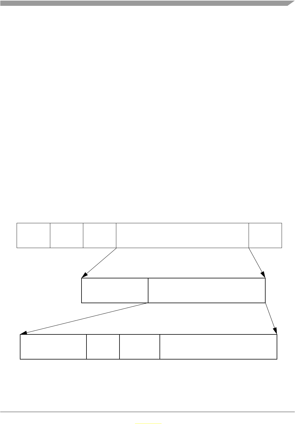
5.3.2 Zpacket Format
The ZSTAR Zpacket is contained inside the MC1319x/MC1321x standard packet structure, which is
consistent with the IEEE 802.15.4 Standard. The SMAC library transparently adds a 16 bit Packet control
field (see chapter 7.2.1.1 of IEEE 802.15.4 Standard specifications) to differentiate packets from ZigBee
and other standards.
The Zpacket becomes a payload data for the SMAC standard packet and contains the following fields:
•5.3.2.1, “Network Number(NetNum)
•5.3.2.2, “RX Strength
•5.3.2.3, “Zcommand
•5.3.2.4, “Zdata
Figure 5-1. Zpacket Format
Preamble SFD FLI Payload Data FCS
MC1319x/MC1321x Packet Structure SFD (Start of Frame Delimiter)
FLI (Frame Length Indicator)
FCS (Frame Check Sequence)
Network number RX
strength Zcommand Zdata
ZSTAR3 Zpacket Structure
Packet control SMAC payload
SMAC Packet Structure
field

Software Design
ZSTAR3 Reference Design Manual, Rev. 0.1
5-34 Freescale Semiconductor
Preliminary
Preliminary
5.3.2.1 Network Number(NetNum)
The network number is save in FLASH memory of each participant with ZSTAR3 RF protocol. The USB
Stick randomly generated it at the first time of lifecycle and it can be changed by command from PC. The
new Sensor board has this number erased from manufacture and it can to update it when it received first
valid packet in ZSTAR3 RF protocol format. Network Number in sensor board can be cleared by pressed
all buttons during wake up sequency of board or it can be changed by command from USB Stick. It is used
to determine between various connections. Packets with different Network numbers are simply ignored.
This field is 16 bits long.
5.3.2.2 RX Strength
This field reports the strength of the last received packet on the other end of the connection. This value
simply tells us how well the other side receives ‘our packets’. This can be used by transmission power
management functions to change the transmission power if the other party receives packets with enough
strength.
The values reported are retrieved using the MLMELinkQuality() SMAC primitive.
This field is 8 bits long.
5.3.2.3 Zcommand
The ZSTAR demo protocol uses a few simple commands to establish and maintain the data flow between
the Sensor Board and USB stick.
The command is carried in 5.3.2.3, “Zcommand field and is 8 bits long. The commands are defined as
listed in Table 5-1., “Original ZSTAR commands Zcommand List, Table 5-2., “ZSTAR3 main commands
Zcommand List, Table 5-3., “ZSTAR3 subcommands Zcommand List.
Table 5-1. Original ZSTAR commands Zcommand List
ZCommand ZCommand
code Direction Zdata
ZSTAR_BROADCAST ‘b’ (0x62) USB stick to Sensor Board none
ZSTAR_ACK ‘a’ {0x61) USB stick to Sensor Board none
ZSTAR_CALIB ‘k’ (0x6B) USB stick to Sensor Board calibration data to Sensor Board
ZSTAR_STATUS ‘s’ (0x73) USB stick to Sensor Board g-range selection data to Sensor Board
ZSTAR_CONNECT ‘c’ (0x63) Sensor Board to USB stick calibration data from Sensor Board
ZSTAR_DATA ‘d’ (0x64) Sensor Board to USB stick
accelerometer values,
temperature and bandgap voltage,
button levels,
g-range selection

Software Design
ZSTAR3 Reference Design Manual, Rev. 0.1
Freescale Semiconductor 5-35
Preliminary
Preliminary
5.3.2.4 Zdata
The 5.3.2.4, “Zdata field follows the 5.3.2.3, “Zcommand field and may be empty if the actual command
doesn’t require any additional data. The data format is dependent on the 5.3.2.3, “Zcommand. A detailed
description is in the next chapter.
5.3.3 Original ZSTAR Zcommand Description
For more detail description of original ZSTAR Zcommands check RD3152MMA7260Q reference design
manual ZSTARRM Reference design manual - Original ZSTAR demo(RD3152MMA7260Q) RDM.
5.3.4 ZSTAR3 Protocol Zcommand Description
All commands with direction Sensor board to USB stick are replinish(lower 4 bits) by information of
sensor index.
Table 5-2. ZSTAR3 main commands Zcommand List
ZCommand ZCommand
code Direction Zdata
ZSTAR3_PYLON 0xA0 USB stick to Sensor Board Status and optional subcommand
ZSTAR3_DATA 0x50 Sensor Board to USB stick Accelerometers values, status info
ZSTAR3_DATA 0x60 Sensor Board to USB stick none
ZSTAR3_CONNECT 0x40 Both Calibration data, board info
ZSTAR3_ION 0x70 Sensor Board to USB stick Optional return read data from ION
Table 5-3. ZSTAR3 subcommands Zcommand List
ZCommand ZCommand
code Direction Zdata
ZSTAR3_GUI ‘g’ (0x67) USB stick to Sensor Board none
ZSTAR3_MODE ‘m’ {0x6D) USB stick to Sensor Board Set up data of new mode
ZSTAR3_OFF ‘o’ (0x6F) USB stick to Sensor Board none
ZSTAR3_GSEL ‘s’ (0x73) USB stick to Sensor Board g-range selection data to Sensor Board
ZSTAR3_DATARATE ‘d’ (0x64) USB stick to Sensor Board new datarate
ZSTAR3_FLAG ‘f’ (0x66) USB stick to Sensor Board none

Software Design
ZSTAR3 Reference Design Manual, Rev. 0.1
5-36 Freescale Semiconductor
Preliminary
Preliminary
5.3.4.1 ZSTAR3_PYLON
This is main and practically single command of USB Stick. Command is used as a net synchronization
message and it’s one way how to get data and other sub commands to individual sensor boards. This
command is replinish in protocol with mode of operation information (8/16 bits communication).
Figure 5-2. ZSTAR3_PYLON Zdata format
5.3.4.2 ZSTAR3_DATA
With this command sensors sensding measured data into USB Stick. This most frequently sensor board RF
command.
5.3.4.3 ZSTAR3_ACK
This command is sensor using to acknowledge success received USB Stick subcommand.
5.3.4.4 ZSTAR3_CONNECT
By this command sensor board sends calibration data to USB Stick. Command is also using to starts
communication between Sensor board and USB stick.
5.3.4.5 ZSTAR3_ION
This command is specially designed to answer all special requirements of digital sensor device1.
5.3.5 ZSTAR3 Protocol SubCommands Description
The group of subcommands relates to main USb Stick RF ZSTAR3_PYLON command. All these
subcommands can be send only as axtension of ZSTAR3_PYLON. Subcommands are way how to get data
and majority commands from USb Stick to individual sensors.
5.3.5.1 ZSTAR3_GUI
This commnad is designed only to clearing timeout2 in sensor and thus keep sensor in run mode.Sensor
board answer by ZSTAR3_DATA command.
1.ZSTAR3 with assembled MMA7450L - ION.
2.Each sensor Board without power switch has automatically switch off function when overflow 2 minutes
timeout.
List of active Data depends on sub commands
01
Zdata bytes:
2
sensors
34...
Selected
Subcommand
sensor

Software Design
ZSTAR3 Reference Design Manual, Rev. 0.1
Freescale Semiconductor 5-37
Preliminary
Preliminary
5.3.5.2 ZSTAR3_MODE
This command is using only with ION device mounted on Sensor Board. Command can swtich individual
digital work modes on digital sensor.Sensor board answer by ZSTAR3_DATA command.
5.3.5.3 ZSTAR3_OFF
This command request switch off sensor. Is available only on Sensor Boards without power switch.
5.3.5.4 ZSTAR3_GSEL
This command is used as a request of change actual g select of sensor to new.Sensor board answer by
ZSTAR3_DATA command.
5.3.5.5 ZSTAR3_DATARATE
This command is used as a request of change actual datarate of sensor to new.Sensor board answer by
ZSTAR3_DATA command.
5.3.5.6 ZSTAR3_FLAG
This is special additional subcommand that is used only with initial ZSTAR_BROADCAST command to
recognize a RF protocol type - Original ZSTAR RF or ZSTAR3 RF Protocol.
5.3.6 ZSTAR3 RF Protocol description
ZSTAR3 Rf portocol is based on star RF network topology. The USB Stick is a master of the network and
Sensor boards are slaves. All network runs within time based RF protocol, thus each device of the ZSTAR3
RF network has own time in each period for transmit. Receive time it’s little different, all Sensor Boards
opens receive window in some time and tries to catch synchronization/data transmition of master, but USB
Stick (master) has opened receive window all time when RF Sensor Boards transmits.
The ZSTAR3 devices runs with simple state machine:
1. Init state - Devices initialize all neccesarry hardware peripherials and software drivers. After
initialization is done, state machine jumps to Broadcast state.
2. Broadcast state: this is little bit outdated state that is keep in protocol only for compatibilities
modes of ZSTAR3 protocol with original protocol devices.
—Master (USB Stick) - the ZStar3 protocol needs only find out free channel for prepared RF
network, but because the ZStar3 demo supports original ZStar RF protocol, then this state is
important only for compatibility capatibilities of the ZSTAR3 demo.
—Slave (Sensor board) - In this state the Sensor Board is looking for the ZSTAR3
communication. Ad when it’s found the RF communication with right NetNum number and its
time position is free, jump to the Run State of RF protocol. If not jumps to the Sleep state.
3. Compatibility state with original ZSTAR:

Software Design
ZSTAR3 Reference Design Manual, Rev. 0.1
5-38 Freescale Semiconductor
Preliminary
Preliminary
—Master (USB Stick) - USB Stick of the ZSTAR3 supports original ZSTAR RF protocol and
this state provide it. For ore details check Manual for original ZSTAR ZSTARRM Reference
design manual - Original ZSTAR demo(RD3152MMA7260Q) RDM.
—Slave (Sensor board) - Sensor board software conteins this state and it can support of original
ZSTAR too, but all boards are ordered with prohibited compatibility.
4. ZSTAR3 Protocol run state:
—Master (USB Stick) - Master is periodically transmiting synchronization ZSTAR3_PYLON
message and then receiving all incoming messages from the Sensor boards within same
NetNum. In this state Master collect all neccessary information about connection status all
Sensor Boards and other user payload.
—Slave (Sensor board) - In this state slave is periodically opening window to receive Master
synchronization mesage, measuring sensor data and tranmitting measured data with exact time
offset to air(master).
5. Sleep state:
— Master (USB Stick) - Doesn’t have this state.
— Slave (Sensor board) - When the Sensor Board goes this state, then switch off all peripheries
on board and inside of microcontroller and prepare all board to at least power consumption.
5.3.6.1 Typical one period of ZSTAR3 RF protocol
The ZSTAR3 RF protocol (in normal run mode) period starts by ZSTAR3_PYLON message from master.
In ideal case all active slaves has opened receive window and catches incoming ZSTAR3_PYLON
message from master. When sleves received this synchronization message, all in same time measure sensor
output values and prepared future trasmition in unique time after ZSTAR3_PYLON message from master.
This time is depend on index of each slave device. In the meantime the master prepared the new receive
window and pens it before first prospektive message of Slave 0 and keeps opened this window until time
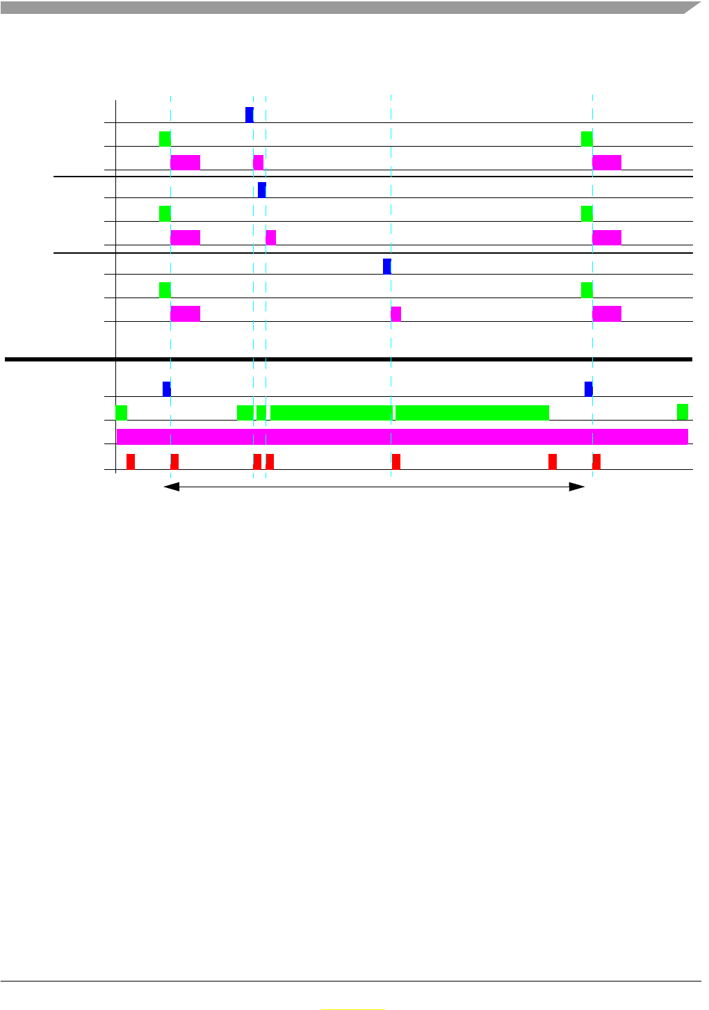
Software Design
ZSTAR3 Reference Design Manual, Rev. 0.1
Freescale Semiconductor 5-39
Preliminary
Preliminary
for all 16 devices elapses. When the master catches any message from slaves, process it and immediatly
open new receive window, if the last message wasn’t from 16th Slave device..
Figure 5-3. ZSTAR3 RF protocol period
5.4 ZSTAR3 USB protocol - Extended STAR protocol
The ZSTAR3 demo uses a subset of the original ZSTAR demo protocol commands.The Original ZSTAR
is build on STAR demo protocol. This way, most of the software originally developed for the
RD3152MMA7260Q (ZSTAR) and RD3112MMA7260Q (STAR) is also usable with the ZSTAR3.
The STAR demo communicates over the RS232 serial line with a simple text-based protocol. The same
protocol is used in ZSTAR/ZSTAR3 for communication between the USB stick and a PC (over a virtual
serial port). The PC application sees the same interface (serial port) and the same protocol as if a STAR
demo was connected.
Because the ZSTAR3 can serve up to 16 connected sensor boards, all commands that works direct with
sensor boards are communicated with one selected board by ‘N’ command from 5.4.3, “Subset of new
added ZSTAR3 protocol commands.
5.4.1 Subset of original STAR protocol commands
The ZSTAR3 software contains all unchanged original STAR commands. Some commands can send
extended information in ZSTAR3 mode - ZSTAR3 USB protocol extend some Original commands when
PC send any command from new subset of command table. These extended information return to PC
information of result individual commands.
Slave 0 Tx
Rx
MCU
Master Tx
Rx
MCU
SMAC Interupts
Slave 1 Tx
Rx
MCU
Slave 8 Tx
Rx
MCU
ZStar3 RF protocol typical period
Software Design
ZSTAR3 Reference Design Manual, Rev. 0.1
5-40 Freescale Semiconductor
Preliminary
Preliminary
Table 5-5. Legend of colors
5.4.2 Subset of original ZSTAR protocol commands
The ZSTAR3 software contains all lightly changed original ZSTAR commands.
Table 5-4. Original STAR commands
Normal Command Extended Asynchronous
Answer
Note
Comma
nd Detail of command data Length
tx/rx
(B) Detail Leng
th rx
(B)
‘R’ ‘N’ 1, 1- - Reset to 8 bit mode
‘V’ ''x' value 'y' value 'z' value 1,61
1Length of answer of measured data depends on actual work mode 8/16bits. 6 bytes for 8 bits, 9 bytes for 16 bits mode
- - Read acceleration data
‘G’ g-select value 1, 1- - g-select read
‘g’ g-select value, ‘G’, result 2, 0, 2 {'g',result,index} 7 g-select write
‘K’ ''X' g(0) g(1) 'Y' g(0) g(1) 'Z' g(0) g(1) 1,. 92
2Length of answer of calibration values depends on actual work mode 8/16bits. 9 bytes for 8 bits, 15 bytes for 16 bits mode
- - read calibration values3
3If is connected sensor with ZSTAR3 protocol, then this command return ideal constants of calibration
‘k’ xg(0), xg(1), yg(0), yg(1), zg(0), zg(1), ‘K’,
result 74, 0, 2
4Length of command calibration data depends on actual work mode 8/16bits. 7 bytes for 8 bits, 13 bytes for 16 bits mode
{'k',result,index} 7 write calibration values5
5If is connected sensor with ZSTAR3 protocol, then command calibration data isn’t important
Legend
Red Direction PC -> USB Stick
Blue Direction USB Stick -> PC, regular
data
Magenta Direction USB Stick -> PC, extended
data
Table 5-6. Original ZSTAR commands
Normal Command Extended
Asynchronous
Answer Note
Comma
nd Detail of command data Length
tx/rx
(B) Detail Leng
th rx
(B)
Software Design
ZSTAR3 Reference Design Manual, Rev. 0.1
Freescale Semiconductor 5-41
Preliminary
Preliminary
Legend of colors
5.4.3 Subset of new added ZSTAR3 protocol commands
The ZSTAR3 software contains all unchanged original STAR commands. Some commands can send
extended information in ZSTAR3 mode - ZSTAR3 USB protocol extend some Original commands when
PC send any command from new subset of command table. These extended information return to PC
information of result individual commands.
‘r’ ‘z’ 1, 1- - Reset to 16 bit mode
‘v’ 'x' value 'y' value 'z' value 's' status 't'
temperature 'b' bangap 1,17 - - Read extended 16 bits
acceleration data1
‘I’ Text information about project 1, -- - Return text information about
ZSTAR project
‘U’ Debug information 1, - - - Switch on sending useful debug
information
‘u’ 1,0- - Switch off sending useful debug
information
‘Q’ ‘Q’ 2, -- - Debug autocalibration command
‘S’ Sensor RSSI, USB RSSI 1, 2- - Read Receive Strength Signal
Indicators
1ZSTAR3 RF protocol does not support bangap and temperature values, thus when USB Stick run with ZSTAR3 RF protocol
this command always returning zeros in these fields
Legend
Red Direction PC -> USB Stick
Blue Direction USB Stick -> PC, regular
data
Table 5-7. New ZSTAR3 commands (general commands)
Normal Command
Note
Comma
nd Detail of command data Length
tx/rx
(B)
‘A’ ‘a’, channel 1, 2return actual select rf channel
‘a’ channel, ‘A’ 2,1set new RF channel, channel > 15 means automatically
selection by USB Stick
‘B’ ‘b’, Working State 1, 2Get actual working state of ZSTAR
‘C’ ‘c’ 1, 1Simply HandShake
Table 5-6. Original ZSTAR commands

Software Design
ZSTAR3 Reference Design Manual, Rev. 0.1
5-42 Freescale Semiconductor
Preliminary
Preliminary
‘H’ ‘h’, netnum 1,. 3 Read Net ID number of RF communication
‘h’ netnum, ‘H’ 3, 1Set new Net ID number of RF communication
‘M’ datarate, ‘m’, result 2, 2Set new datarate of sensor
‘m’ datarate 1, 1Read actual datarate of sensor
‘N’ sensor index, ‘n’, result 2, 2Change focus of communication to new sensor index
‘n’ sensor index, connected sensors mask 1, 3Read index of focused sensor and mask of connected
sensors
‘O’ 'X' calibration offset 'Y' calibration offset 'Z'
calibration offset 1, 6Get true calibration offset values generated by
autocalibration process
‘W’ sensor type,board type, sensor subtype,
ZSTAR version 1, 5Read information about type of board, sensor and USB Stick
‘X’ burst sensor mask, ‘x’, connected sensors
mask 3, 3Switch on burst mode of ZSTAR
‘x’ ‘X’ 1, 1Switch off burst mode of ZSTAR
‘Z’ ‘z’ 1, 1Go to Bootloader device
Table 5-8. New ZSTAR commands (Digital sensor part)
Normal Command Extended
Asynchronous
Answer Note
Comma
nd Detail of command data Length
tx/rx
(B) Detail Leng
th rx
(B)
‘J’ address of reg, length of data, new values of
reg 1-6 bytes, 'j', result 3-9, 2 {‘J’,result,index} 7 Direct access into ION registers,
write
‘j’ address of reg, length of reading, 'J', result 3, 2 {‘j’,result,data 2
- 8 x2 Bytes} 9-23 Direct access into ION registers,
read
L’ LDTH, SetByte, 'l', result 3, 2 {‘L’,result,index} 7 Level treshold detection switch on
‘l’ 'L', result 1, 2 {‘l’,result,index} 7 Level treshold detection switch off
‘P’ PDTH, PW, LT, TW, Setbyte, ‘p’, result 6,2 {‘P’,result,index} 7 Pulse detection switch on
‘p’ 'P', result 1, 2 {‘p’,result,index} 7 Pulse detection switch off
‘>’ Digital interface, ‘<‘, result 2, 2 {‘>’,result,index} 7 Change type of digital interface on
communixcation with ION
‘<’ ‘>’, Digital interface 1, 2- -Read type of digital interface on
communixcation with ION
Table 5-7. New ZSTAR3 commands (general commands)

Software Design
ZSTAR3 Reference Design Manual, Rev. 0.1
Freescale Semiconductor 5-43
Preliminary
Preliminary
Table 5-9. Legend of colors
5.4.4 Burst mode
A new mode of ZSTAR USB communication is burst mode. The Burst mode is designed to symplification
reading process of new acceleration data. In burst mode USB Stick is sending all new received acceleration
data from individual enabled sensor boards without any request command from PC.
Burst mode content:
• time of receive - 24bits time information with 4 us step
• manage byte - contain actual datarate, mode 8/16bits and index of Sensor board
• acceleration data + data status - this field can be multiply repeat up to 4 samples depends on actual
datarate
• Status - contains information about select g range, buttons and events of last sample
Burst mode frame formats examples:
[ttttttmmxxyyzzddss] - 8 bits 30Hz frame
[ttttttmmxxxxyyyyzzzzddss] - 16 bits 30Hz frame
[ttttttmmxxxxyyyyzzzzddxxxxyyyyzzzzddxxxxyyyyzzzzddxxxxyyyyzzzzddss] - 16 bits 120Hz frame -
worest case of communication
where is: t - receive time, m - manage byte, x- accelariotion in X axis, y- accelariotion in Y axis, z-
accelariotion in Z axis, d - data status byte, s - frame status byte, [ - start char and ] is end char of frame.
Real example of burst mode frame:
”[BBBCDCA0D0001400400000D6002C00410000D9002D003D0000E1002F003D000020]”.
5.4.5 Network Lock feature of ZSTAR3 protocol
The ZStar3 RF protocol brings a new network lock function.This feature allow provide more ZSTAR3
networks in one RF space. For more details check section 5.3.2.1, “Network Number(NetNum).
5.4.6 Semiautomatic Self-Calibration
For the purpose of easier semiautomatic calibration of the ZSTAR demo with out PC GUI, the additional
Calibration command ‘Q’ (0x51) has been added. This command is usually issued over terminal (e.g.
HyperTerminal) software.
Legend
Red Direction PC -> USB Stick
Blue Direction USB Stick -> PC, regular
data

Software Design
ZSTAR3 Reference Design Manual, Rev. 0.1
5-44 Freescale Semiconductor
Preliminary
Preliminary
A user is required to place the Sensor Board into horizontal position(for example on a desk), in which the
earth’s gravity will induce a maximum acceleration in Z axis.First command ‘Q’ sent to USB Stick only
prepare user to calibration by text help and second commnad ‘Q’ in line starts autocalibration process in
Sensor board.
5.5 Compatiblity with Original ZSTAR
The new ZSTAR3 and new USB stick sw are fully compatible with original ZSTAR on USB
communication, thus can be used all application designed for original ZSTAR as demo application
RD3152MMA7260Q_SW. Compatibility was reach by keeping all original commands in communication
protocol on USB.
USB Stick provides compatibility mode with original ZSTAR RF protocol. If first devices in brodcast
mode is Sensor Board with original software, USB Stick is switched to Compatibility mode and start
original ZSTAR RF protocol. When is Compatibility mode is active, any sensor can’t be connect.
5.6 Bootloader
There’s bootloader software implemented in MCHC908JW32 microcontroller. The bootloader is based on
1., “AN2295 Application note - Developer’s Serial Bootloader for M68HC08 and HCS08 MCUs and
AN2295SW related software. The original AN2295 bootloader targets serial connections between the PC
and applications, and since the MCHC908JW32 implements a virtual serial port application, the USB
version of the AN2295 bootloader has been created to allow reprogramming of Flash memory in the USB
stick.
The USB virtual serial port software is fully described in 2., “AN3153 Application note - Using the
Full-Speed USB Module on the MCHC908JW32. The MCHC908JW32 bootloader implements the same
virtual serial port but under a different PID (the PC sees that serial port as a different application from
ZSTAR).
The bootloader drivers installation guide can be found in Section 6.1.2, “AN2295 Bootloader Drivers
installation.
5.6.1 Switch to Bootloader procedure
The Bootloader in the ZStar is starts very simply by followed procedure:
1. Unplug the USB Stick from USB port.
2. Press and keep the button on the USB Stick.
3. Keep pressed button and plug the USB Stick back to the USB port.
4. Release the button.
Software Design
ZSTAR3 Reference Design Manual, Rev. 0.1
Freescale Semiconductor 5-45
Preliminary
Preliminary
5.6.2 Bootloading Procedure
The easiest way how to Flash newest firmware into USB Stick is use The ZStar3 GUI application and by
this application open Bootloader COM port1. But if you want proceed Bootloader procedure manually,
yhen follow next steps.
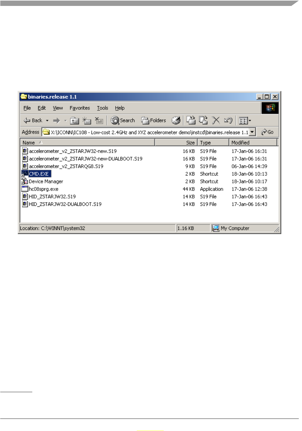
1. Find on the installation CD the folder with binaries:
2. Start (double-click) the CMD.EXE shortcut, a command line window should appear:
1. For more details check Chapter 7 of this Manual.
Software Design
ZSTAR3 Reference Design Manual, Rev. 0.1
5-46 Freescale Semiconductor
Preliminary
Preliminary
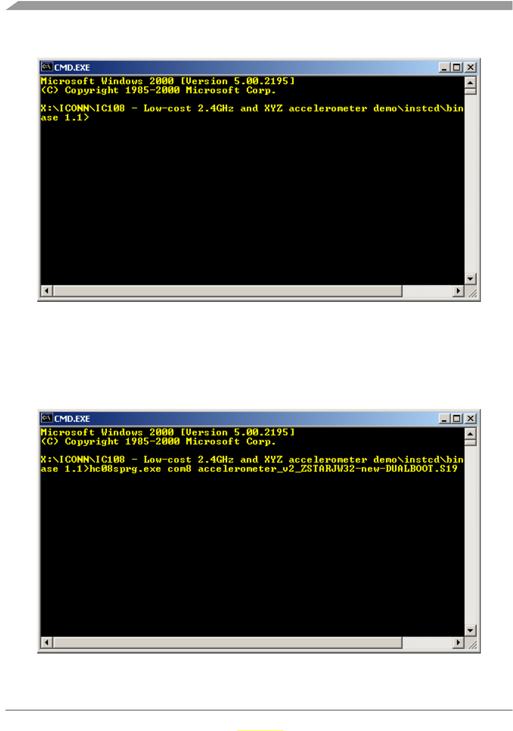
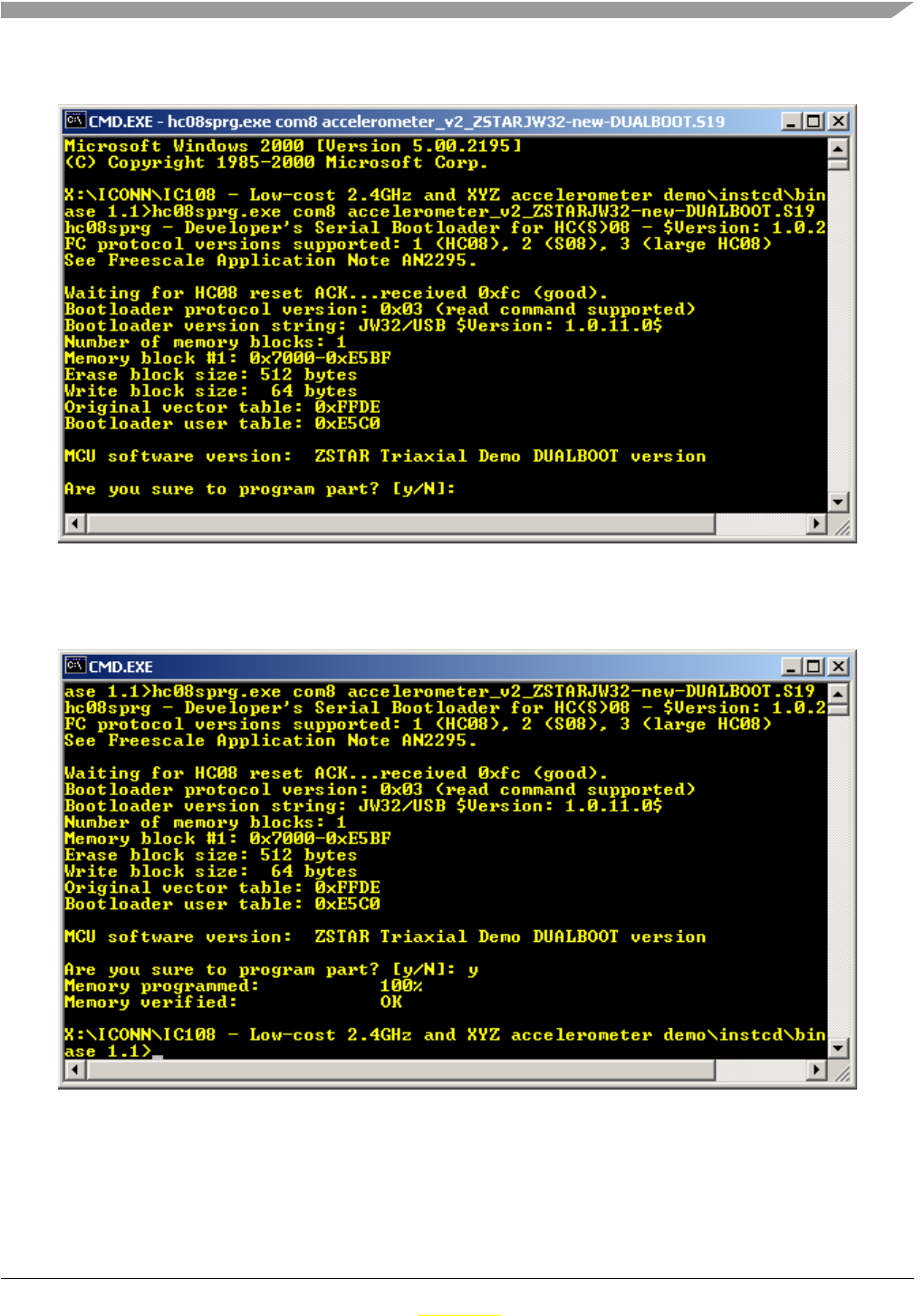
3. Now type: hc08sprg [bootloader com port number] [binary (S file) that you want to bootload], just
like this:
hc08sprg.exe com8 accelerometer_v2_ZSTARJW32-new-DUALBOOT.S19
4. Press ENTER and initial bootloader communication will start:
Software Design
ZSTAR3 Reference Design Manual, Rev. 0.1
Freescale Semiconductor 5-47
Preliminary
Preliminary
If this screen does not appear, remove the USB stick and start from the beginning.
The bootloader disappears (in Device Manager) and the newly loaded software starts to execute.
Using this procedure the software in the USB stick can be changed anytime.

Software Design
ZSTAR3 Reference Design Manual, Rev. 0.1
5-48 Freescale Semiconductor
Preliminary
Preliminary
5.7 Triapplication software of USB Stick
USB Stick provides three different USB devices that can be changed in runtime. List of ZSTAR USB
Devices:
• CDC (Communication Device Class) - virtual serial port.
• HID (Human interface device) - Mouse device
• HID (Human interface device) - Keyboard device
5.7.1 CDC - Virtual Serial Port application
This is main application of ZSTAR3 project. Only this one application can provide ZSTAR3 USB protocol
(extended STAR protocol) commands and run all functionalitis and features of ZSTAR3 demo.
5.7.2 HID - Mouse application
The second application of ZSTAR USB Stick is computer mouse demo. This application looks like the real
USB mouse. Only Sensor board with index 0 can works as input device. Move of cursor on screen is done
very simply by titl of sensor board in axes XY. First two buttons on sensor board has same function as
buttons on real mouse. Third button that brings new ZSTAR3 sensor boards substitute a wheel of real
mouse. When you keep this button pushed, cursor stops move on screen and USB Stick starts generate
wheel movement from Y axis.
5.7.3 HID - Keyboard application
The third application has very specific target of end application, main is controller for simply PC games
controlled by keyboard. This application looks like general USB keyboard. The USB stick simulated
pressing keys on keyboard by tilt of the sensor boards. ZSTAR recognizes four steps of tilt and by this
generated frequency and dury cycle of pressed keys. This feature helps to better game control. ZSTAR
suport 6 first Sensor Boards indexes. Each index has assign four keys by table bellow:
Very nice freeware game that we used for testing is GeneRally form http://generally.rscsites.org/ site.
Index Up Down Left Right
0wsad
1tgfh
2ikj l
3zxcv
4bnmp
51234

Software Design
ZSTAR3 Reference Design Manual, Rev. 0.1
Freescale Semiconductor 5-49
Preliminary
Preliminary
5.7.4 Applications Switching
All embedded application can be switched just by quickly pressing the button (having the USB stick
inserted into the USB slot). The applications will appear and disappear accordingly.
The ‘tilt’ mouse application in order to work must have Sensor Board calibrated correctly (e.g. using
RD3152MMA7260Q_SW.exe or 5.4.6, “Semiautomatic Self-Calibration procedure).

Software Design
ZSTAR3 Reference Design Manual, Rev. 0.1
5-50 Freescale Semiconductor
Preliminary
Preliminary
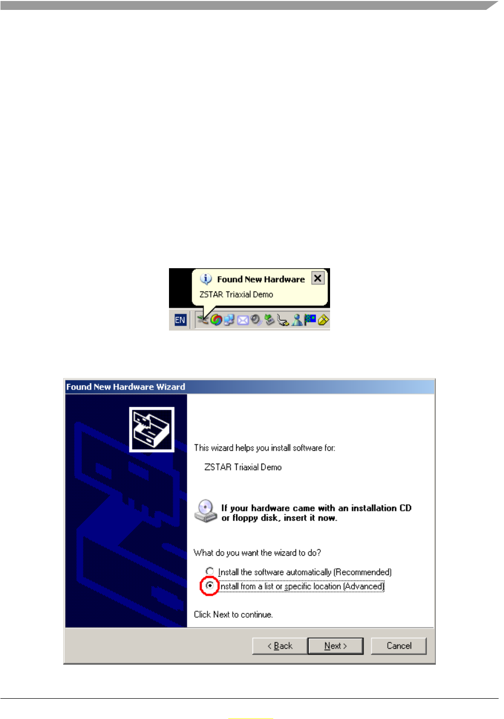
ZSTAR3 Reference Design Manual, Rev. 0.1
Freescale Semiconductor 6-51
Preliminary
Preliminary
Chapter 6
Application Setup
6.1 ZSTAR3 Installation Procedure
6.1.1 USB stick Installation
First of the all, we have to install the USB stick to your PC. Please follow the next steps.
1. Plug the USB stick into a USB slot.The ‘Found New Hardware’ announcement should appear:
2. Then the installation wizard starts for new hardware. Choose “Install from a list or special location“
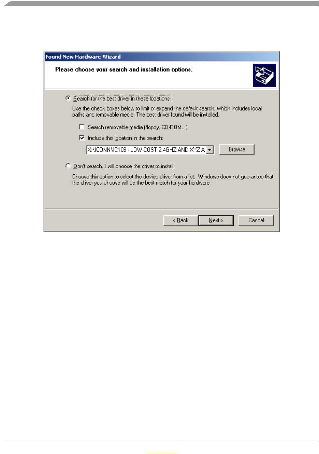
Application Setup
ZSTAR3 Reference Design Manual, Rev. 0.1
6-52 Freescale Semiconductor
Preliminary
Preliminary
3. Point to the Installation CD as the driver path:
4. Installation should continue:
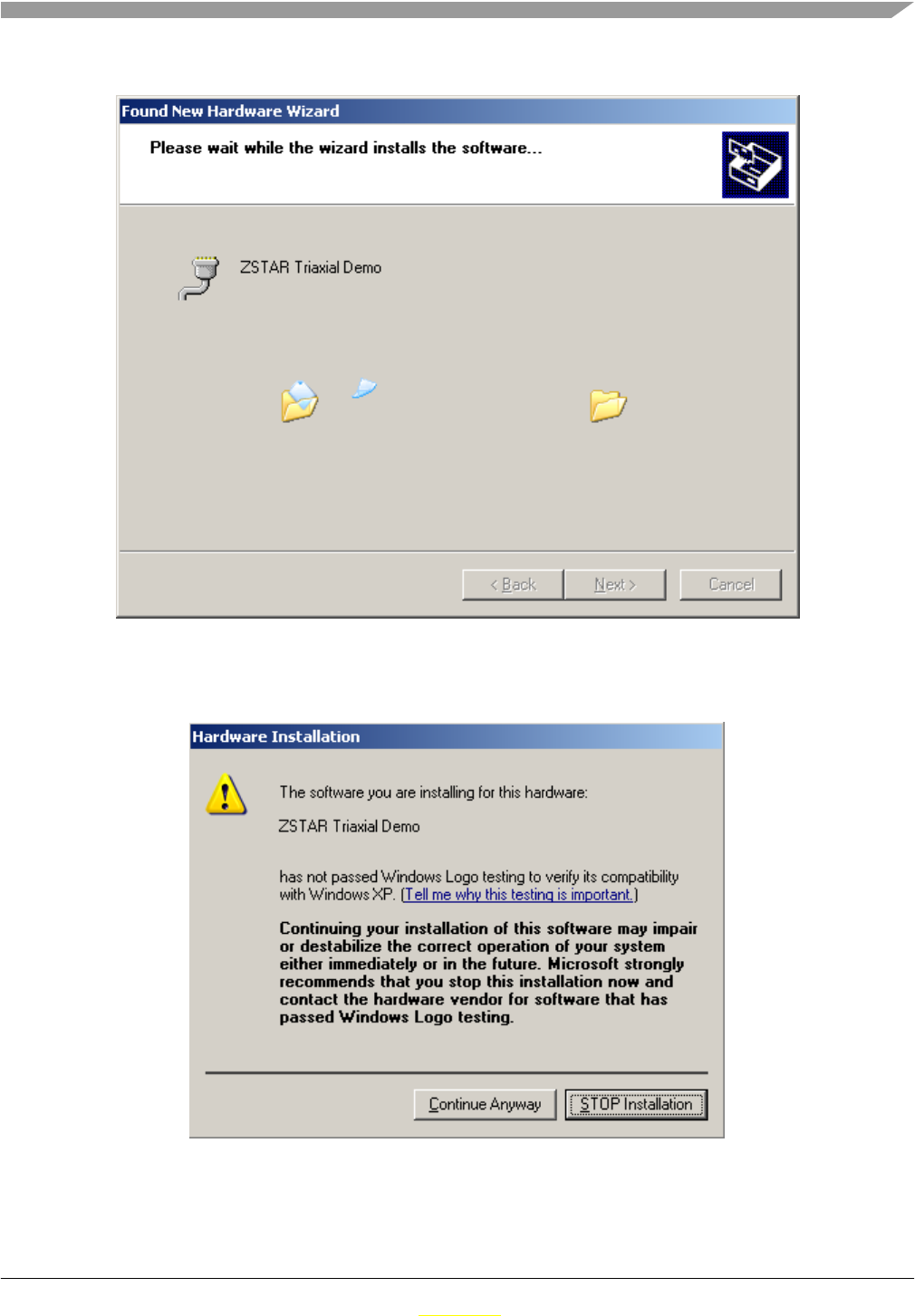
Application Setup
ZSTAR3 Reference Design Manual, Rev. 0.1
Freescale Semiconductor 6-53
Preliminary
Preliminary
5. If you are asked to stop or continue installation because the drivers are not certified by
Microsoft, select the “Continue Anyway” button.
6. Installation should successfully finish.
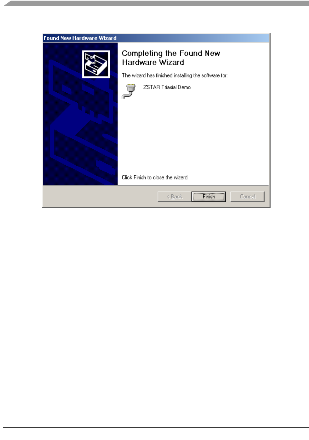
Application Setup
ZSTAR3 Reference Design Manual, Rev. 0.1
6-54 Freescale Semiconductor
Preliminary
Preliminary
7. Check whether a new serial port (ZSTAR Triaxial Demo) has appeared in your Device Manager
(Right click My computer on the Desktop > Properties, Hardware tab, Device Manager button):
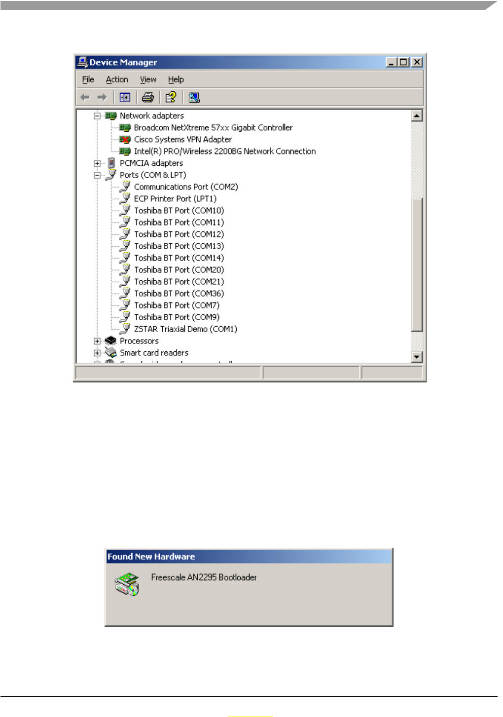
Application Setup
ZSTAR3 Reference Design Manual, Rev. 0.1
Freescale Semiconductor 6-55
Preliminary
Preliminary
6.1.2 AN2295 Bootloader Drivers installation
This procedure assumes that ZSTAR Demo drivers are already installed. The drivers are false common for
the bootloader (= are already present in Windows folders). If not, the procedure will be identical to the
ZSTAR drivers installation.
1. Press the Button on the USB stick and insert it into a USB connector (keeping the button pressed
when inserted).
The following window appears:
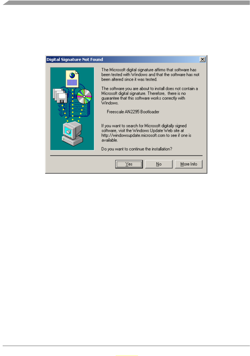
Application Setup
ZSTAR3 Reference Design Manual, Rev. 0.1
6-56 Freescale Semiconductor
Preliminary
Preliminary
2. The PC searches for an appropriate driver (as the ZSTAR Demo, in some instances a folder with
drivers (zstar.inf and usbser-zstar.sys) needs to be selected), then the following
window should appear:
3. Just click Yes, and the bootloader port will be installed (as seen in the Device manager):
4. Right click My computer on the Desktop > Properties, Hardware tab, Device Manager button.
5. A similar setup should be observed:
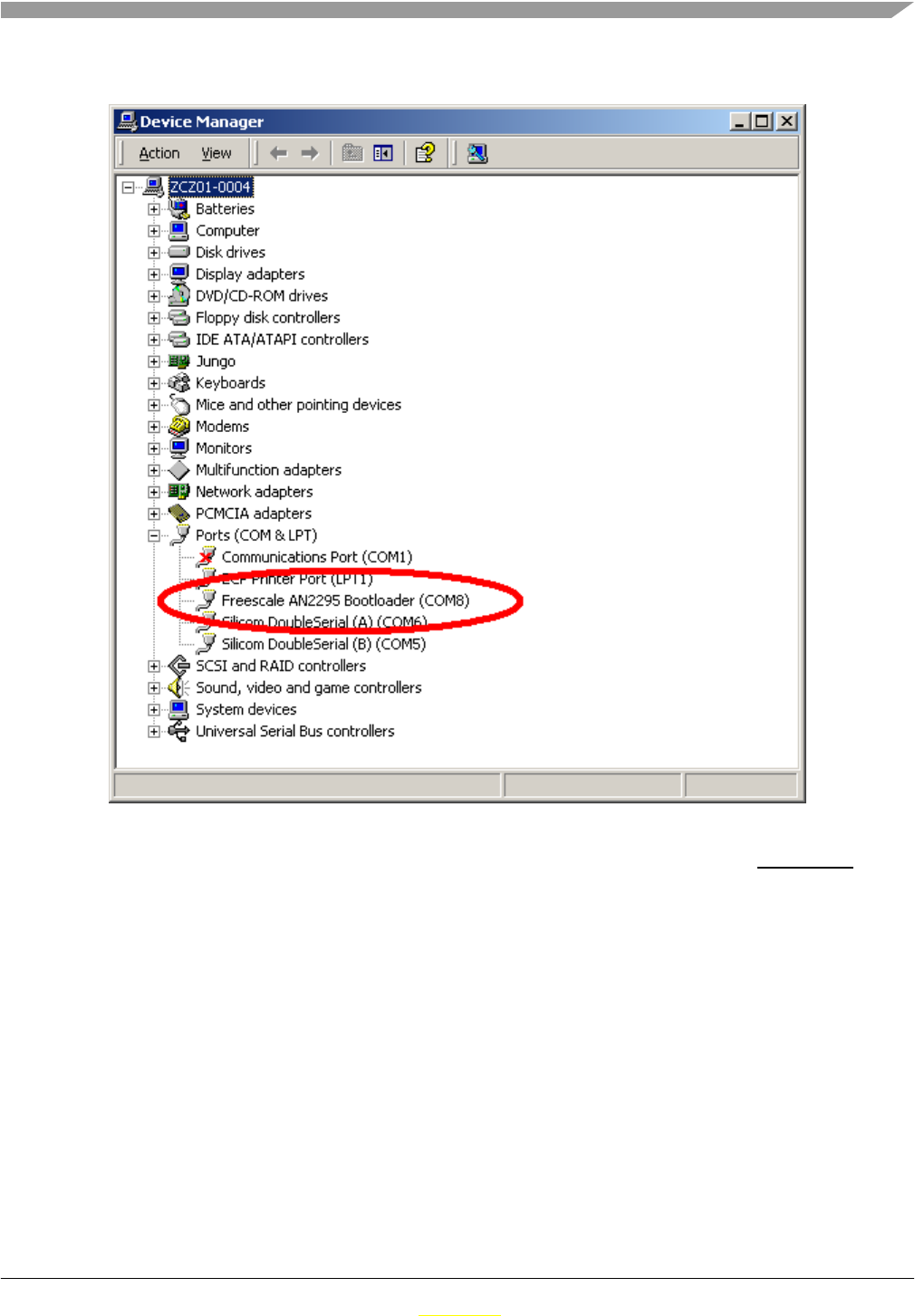
Application Setup
ZSTAR3 Reference Design Manual, Rev. 0.1
Freescale Semiconductor 6-57
Preliminary
Preliminary
6. Note down the COM port number (here, COM8); this is the port number of the Bootloader
Once the software in the USB stick needs to be updated, the Bootloader can be invoked anytime, just by
pressing the button while inserting the USB stick into the USB slot.

Application Setup
ZSTAR3 Reference Design Manual, Rev. 0.1
6-58 Freescale Semiconductor
Preliminary
Preliminary
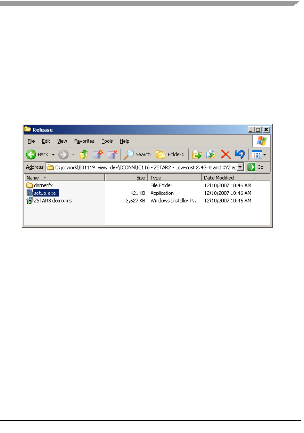
ZSTAR3 Reference Design Manual, Rev. 0.1
Freescale Semiconductor 7-59
Preliminary
Preliminary
Chapter 7 ZSTAR3 GUI
ZSTAR3 demo brings new GUI that supports all new features and functions. It’s distibuted as complete
installation package with all neccesary files, includes Microsoft .NET Framework package.
7.1 Installation
1. Run setup.exe file in installation directory to start installation of ZStar3 GUI to computer.
Figure 7-1. Installation files
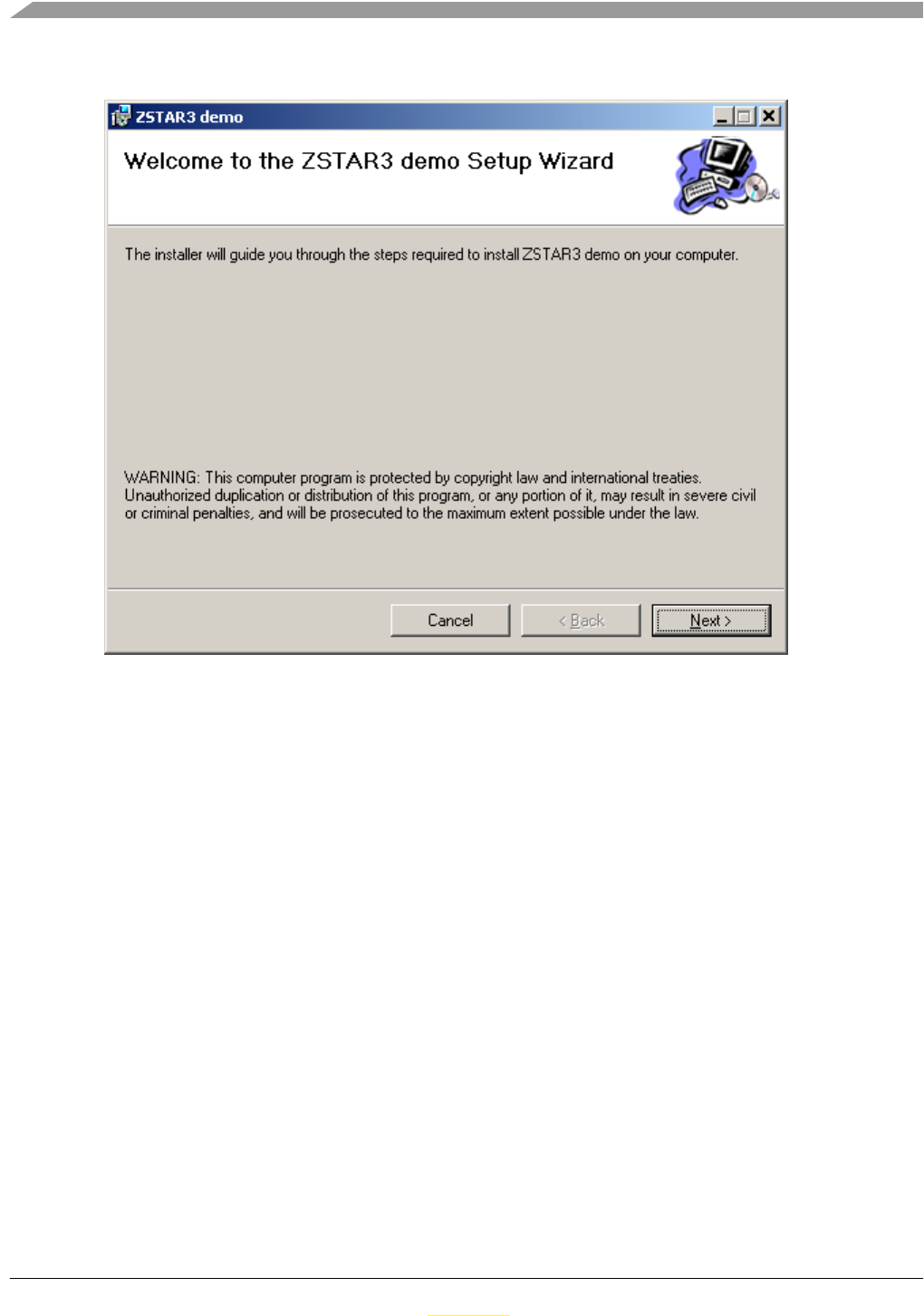
ZSTAR3 GUI
ZSTAR3 Reference Design Manual, Rev. 0.1
7-60 Freescale Semiconductor
Preliminary
Preliminary
2. On first screen of ZStar3 installation packege only press “next“ button.
Figure 7-2. Start of installation
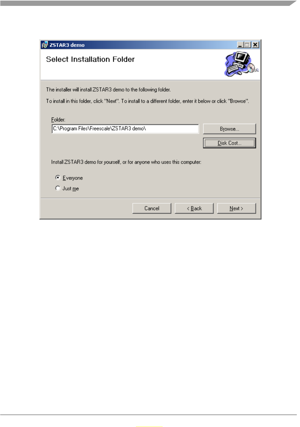
ZSTAR3 GUI
ZSTAR3 Reference Design Manual, Rev. 0.1
Freescale Semiconductor 7-61
Preliminary
Preliminary
3. In this step select destination directory and some others posibilities and press “next“ button. Please
follow all next steps to get to end of installation process.
Figure 7-3. Second step of installation process - select destionation directory

ZSTAR3 GUI
ZSTAR3 Reference Design Manual, Rev. 0.1
7-62 Freescale Semiconductor
Preliminary
Preliminary
4. Finish step of the installation process.
Figure 7-4. Last step of the installation process
7.2 ZSTAR3 GUI
The ZSTAR3 GUI is specially designed PC application for Freescale ZStar demos. It’s fully supports all
new functionalitis of the ZSTAR demo and all available ZSTAR boards.
7.2.1 Features of ZSTAR GUI
• Support 16 sensors on one screen. Shows for each sensor basic information includes current
acceleration values and freefall events.
• Easy select of active sensor board.
• Detail window of selected sensor board on overview screen.
• RF page that shows all RF settings and informations. RF settings as the Netnum, RF channel are
modicable by this screen.
• Lot of various demos of typical accelerometers applications or Freescale sensors presentation.
• User help by about screens in most of demo windows.
• Update function for old ZSTAR USB Sticks. The GUI can reflash all old USB Stick boards with
newest software that is compatible with software of old Sensor boards.
• USB data flow monitor
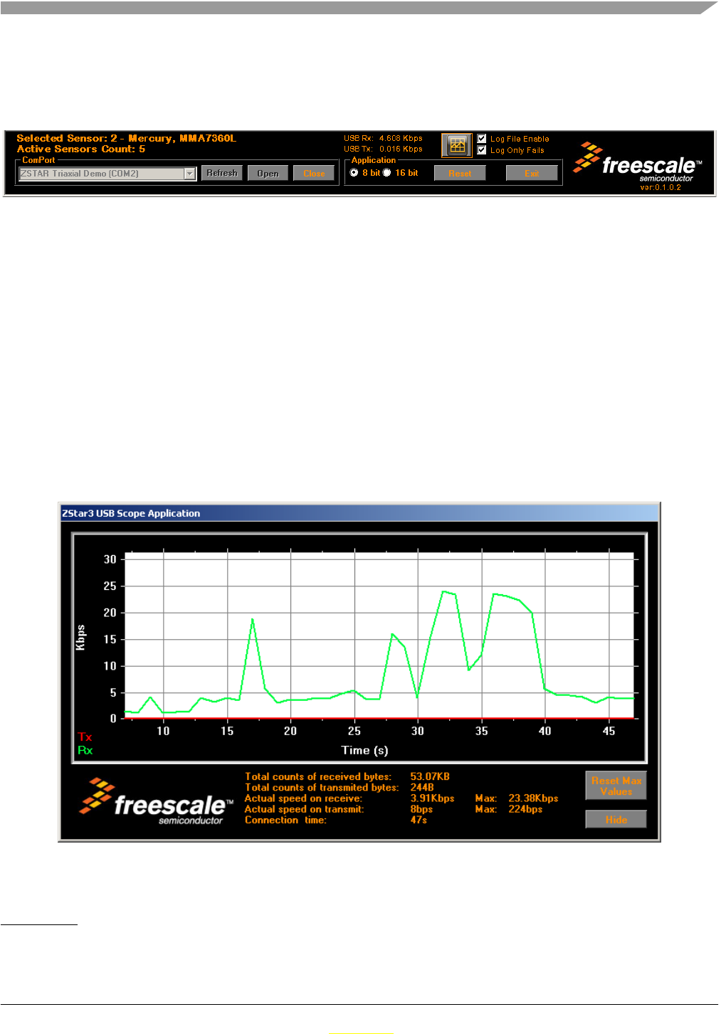
ZSTAR3 GUI
ZSTAR3 Reference Design Manual, Rev. 0.1
Freescale Semiconductor 7-63
Preliminary
Preliminary
7.2.2 The ZStar3 GUI main controls
This panel is visible on all tabs of ZStar3 GUI application. It shows the most important controls and
information of ZStar demo.
Figure 7-5. The ZStar3 GUI main controls
The GUI main controls1:
1. USB Stick connection panel.
2. The ZStar resolution switch 8/16 bits.
3. Reset of the ZStar hardware.
4. USB data flow monitor.
5. Log file controls.
6. Information of count of total connected sensor boards and currently selected one.
7.2.2.1 USB Data Flow monitor
This is special window designed for Monitoring data rates of communication via USB interface2. Window
shows all baic information of current USB load and its draw graph of last 40 seconds.
Figure 7-6. USB Data Flow Monitor
1. Red numbers in picture marks individual controls described in list below.
2. Only user payload - ZStar data.
1
23
45
6
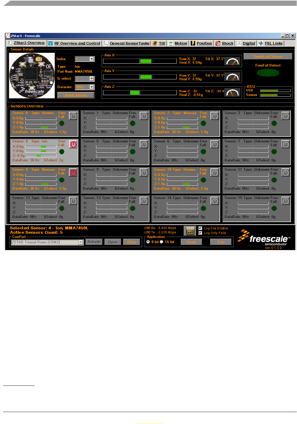
ZSTAR3 GUI
ZSTAR3 Reference Design Manual, Rev. 0.1
7-64 Freescale Semiconductor
Preliminary
Preliminary
7.2.3 Sensor Board overview screen
Figure 7-7. Main sensor board overview screen of the GUI
The GUI main sensor board overview controls1:
1. Detail panel of Selected sensor board.
2. Current accelerometric data in graphical and text form.
3. Current tilt of selected board in graphical and text form.
4. Basic settings of selected sensor board.
5. Log file controls.
6. Currently connected sensors
7. Selected active sensor board.
8. Free slots for Sensor boards.
1. Red numbers in picture marks individual controls described in list below.
1
23
4
5
5
5
5
6
77
7
7
7
77
7
7
77
5
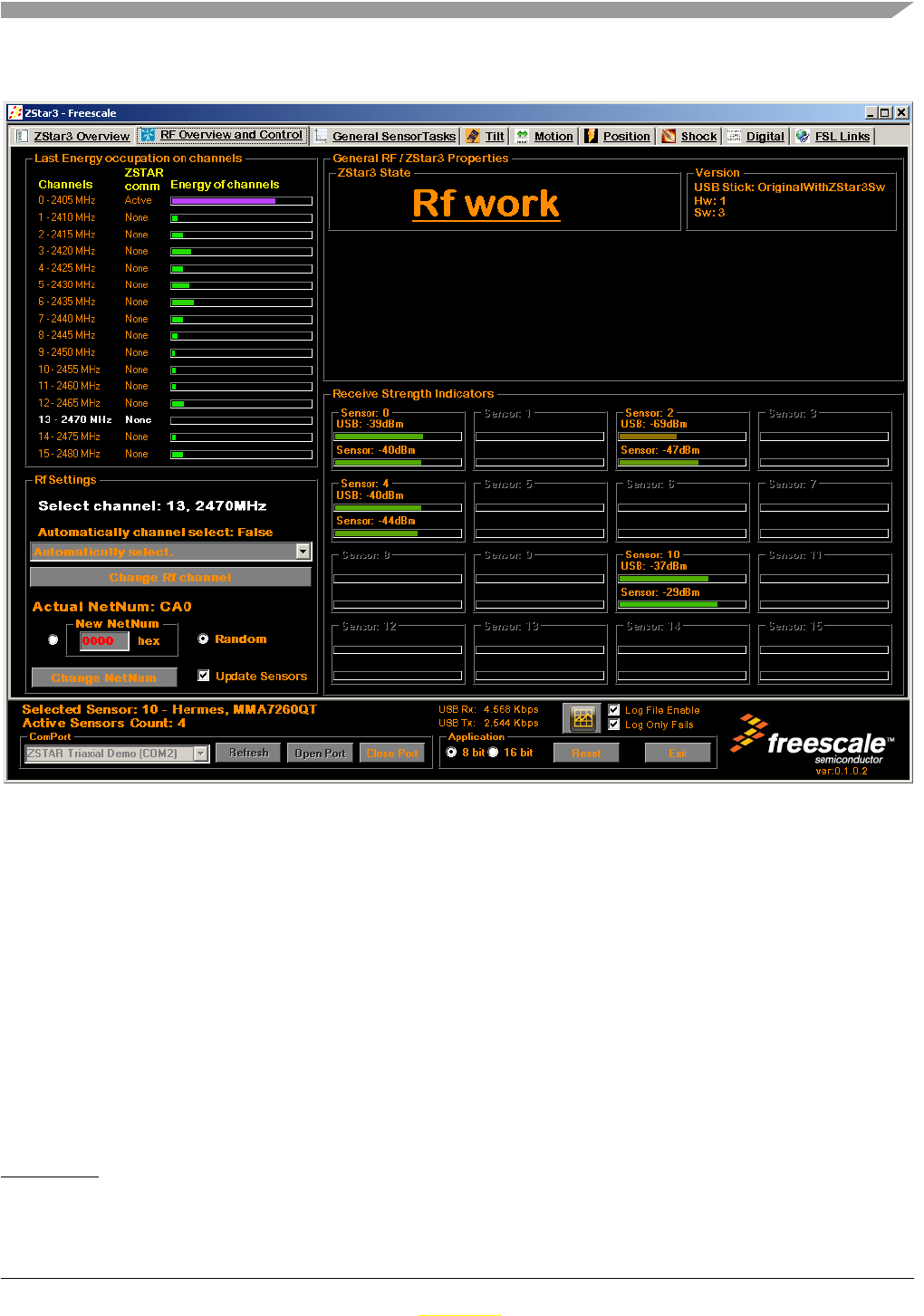
ZSTAR3 GUI
ZSTAR3 Reference Design Manual, Rev. 0.1
Freescale Semiconductor 7-65
Preliminary
Preliminary
7.2.4 RF overview screen
Figure 7-8. RF overview screen
The GUI RF overview controls1:
1. Current work state of the ZStar demo.
2. Last measured information about occupations of indidual RF channels.
3. Flags of detected other ZStar communication on other channels.
4. Current used RF channel.
5. RF channel change control.
6. Netnum of RF communication change control.
7. RSSI2 informations of all connected sensors.
8. Versions of the Demo.
1. Red numbers in picture marks individual controls described in list below.
2. Receive signal strength information.
1
23
4
4
5
6
7
8
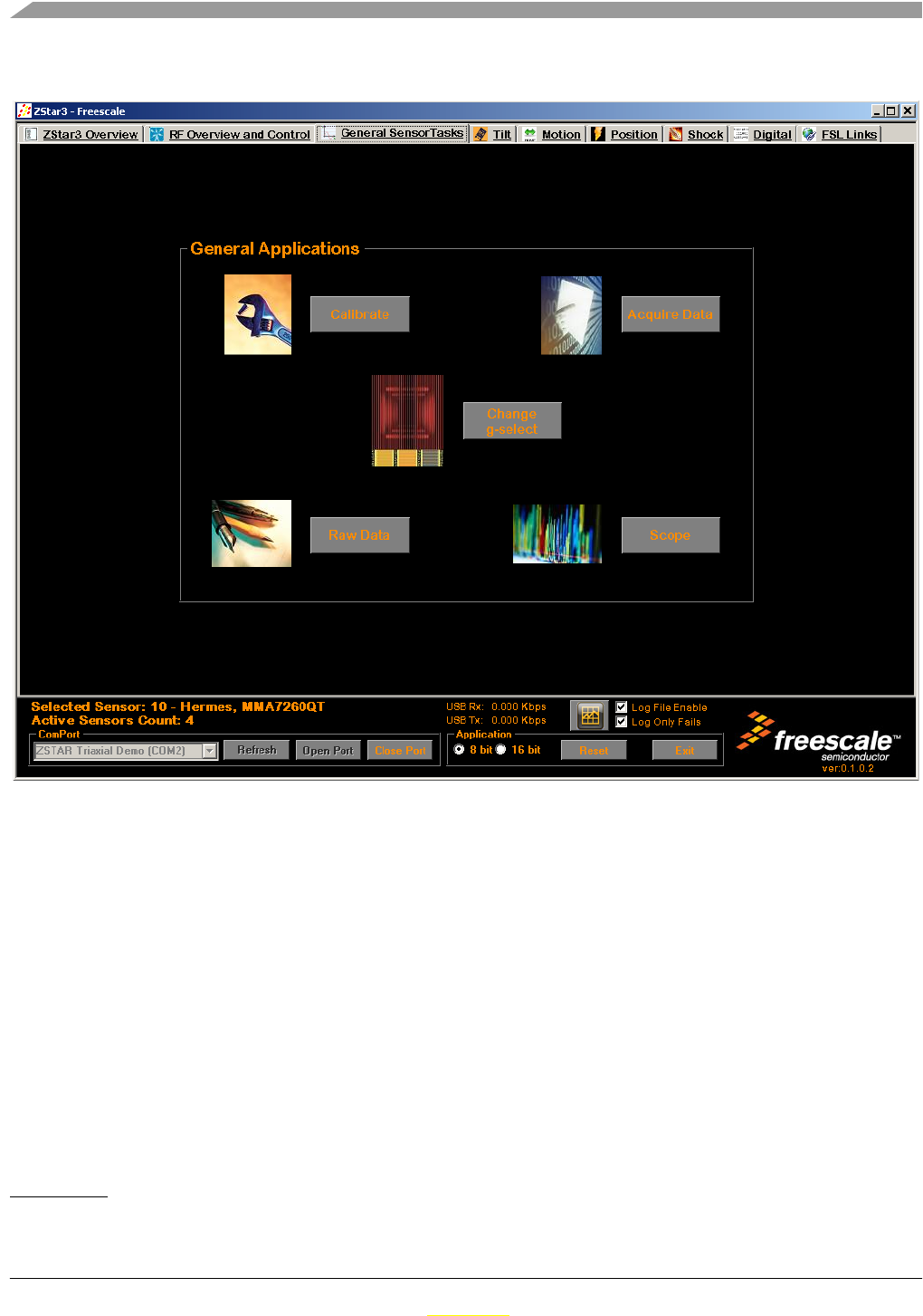
ZSTAR3 GUI
ZSTAR3 Reference Design Manual, Rev. 0.1
7-66 Freescale Semiconductor
Preliminary
Preliminary
7.2.5 General sensor tasks
Figure 7-9. The General sensor tasks screen.
The GUI General sensor tasks controls1:
1. Calibration screen - This screen allowed with more detail calibrate sensor on selected Sensor
Board.
2. Acqire data screen - This application of the ZStar provides a acquire data of all connected sensors
into Excel or text file.
3. Change g select screen - This screen allowed simply change of current g range on selected sensor
board.
4. Raw data screen - This screen shows basic data of Sensor board in general text format.
5. Scope window - This is very usefull window that it shows acceleration in various formats selectable
by user.
1. Red numbers in picture marks individual controls described in list below.
1
2
3
45
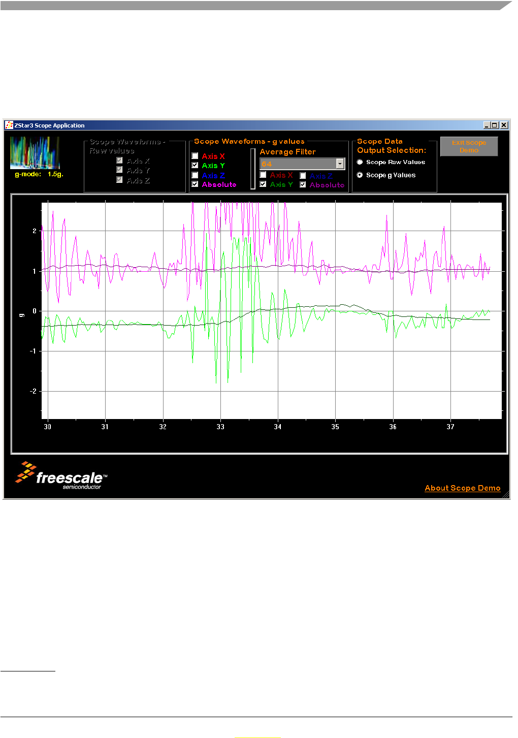
ZSTAR3 GUI
ZSTAR3 Reference Design Manual, Rev. 0.1
Freescale Semiconductor 7-67
Preliminary
Preliminary
7.2.5.1 Scope demo application
This demo application shows graphical outputs of measured and computed values from selected sensor
board.It can shows unchanged raw data received direct from sensors or computed values in g. This window
as well provides computed absolute value from all three axes. All computed values can be displayed as
filtered.
Figure 7-10. Scope window application
The Scope window application controls1:
1. Data source selection - Select which data will be dispalyed, RAW or REAL.
2. Raw data panel - in this panel you can select which axes will be displayed.
3. Real data panel - in this panel you can select which axes will be displayed.
4. Filtered real data panel - in this panel you can select which filtered axes will be displayed and order
of average filter.
1. Red numbers in picture marks individual controls described in list below.
1
234
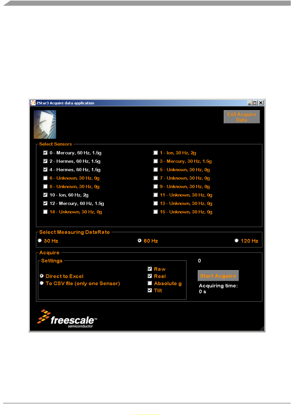
ZSTAR3 GUI
ZSTAR3 Reference Design Manual, Rev. 0.1
7-68 Freescale Semiconductor
Preliminary
Preliminary
7.2.5.2 Acquire data demo application
This application is designed to acquiring all maesured data from sensor. It allow select sensors to
acquiring, select data rate of reading acceleration values, select which data will be saves and output of
measured data. Thre are two choices of output:
• Direct to Microsoft Excel application (tested on Excel 2003 version).
• To CSV file - GUI save all measured data into text file that can be simply imported to Excel or
another table application.
The capture time is not restricted..
Figure 7-11. Acquire data window
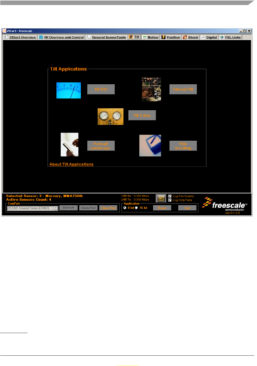
ZSTAR3 GUI
ZSTAR3 Reference Design Manual, Rev. 0.1
Freescale Semiconductor 7-69
Preliminary
Preliminary
7.2.6 Tilt tasks
Figure 7-12. The Tilt tasks screen.
The GUI Tilt tasks controls1:
1. Tilt XYZ screen - Window shows tilt of all axes. Selectable normal / filtered values.
2. Filtered tilt - This application of the ZStar shows differencies beetwen normal measured tilt and
filtered.
3. Tilt 2 Axes screen - This is special demo application that shows how can get from two axes full
range of tilt 0° - 360°.
4. Portrait/Landscape screen - This demo shows one of couple detection tilt applications for PDA.
5. PDA Scrolling screen - This demo shows one of couple detection tilt applications for PDA.
6. About box - This about box content various information about Tilt accelerometers applications.
1. Red numbers in picture marks individual controls described in list below.
1
2
3
45
6
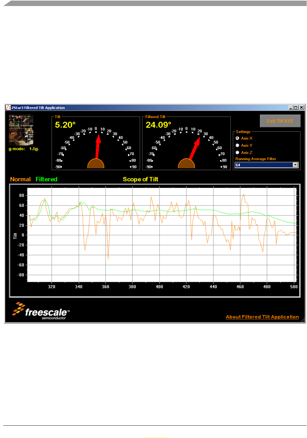
ZSTAR3 GUI
ZSTAR3 Reference Design Manual, Rev. 0.1
7-70 Freescale Semiconductor
Preliminary
Preliminary
7.2.6.1 Filtered tilt demo application
This demo window shows different between measured tilt values and software filtered. This demo is using
basic average filter algorithm. On screen is placed four panels:
• Current measured tilt indicator.
• Filtered value of current measured value indicator.
• Setting box - there can be select measured axis of accelerometer and order of average filter up to
128 samples.
• Scope that shows differencies between current and filtered value in time.
Figure 7-13. Filtered tilt demo application
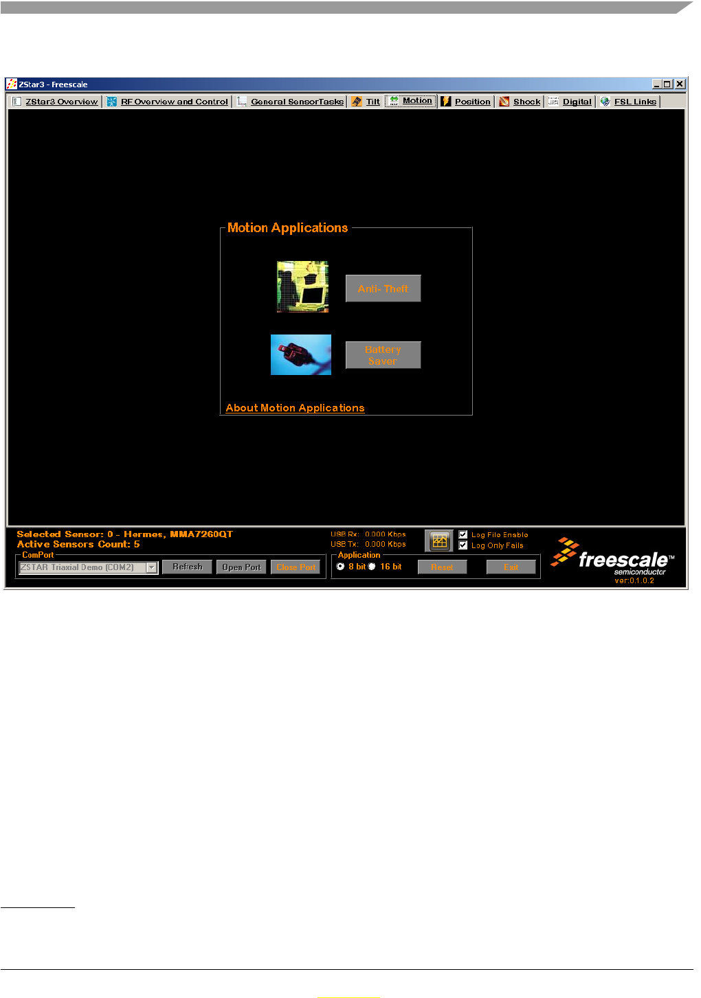
ZSTAR3 GUI
ZSTAR3 Reference Design Manual, Rev. 0.1
Freescale Semiconductor 7-71
Preliminary
Preliminary
7.2.7 Motion tasks
Figure 7-14. The Motion tasks screen.
The GUI Motion tasks controls1:
1. Anti-Theft screen - Window shows accelerometr posibilities in Anti - Theft applications.
2. Battery saver screen - This is demo that shows How can used accelerometers in some specific
applications to save battery.
3. About box - This about box content various information about Motion accelerometers applications.
1. Red numbers in picture marks individual controls described in list below.
1
2
3
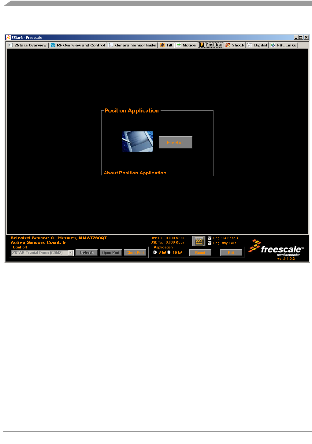
ZSTAR3 GUI
ZSTAR3 Reference Design Manual, Rev. 0.1
7-72 Freescale Semiconductor
Preliminary
Preliminary
7.2.8 Position tasks
Figure 7-15. The Position tasks screen.
The GUI Position tasks controls1:
1. FreeFall screen - Demo shows accelerometer possibilities of FreeFall detection.
2. About box - This about box content various information about Position accelerometers
applications.
1. Red numbers in picture marks individual controls described in list below.
1
2
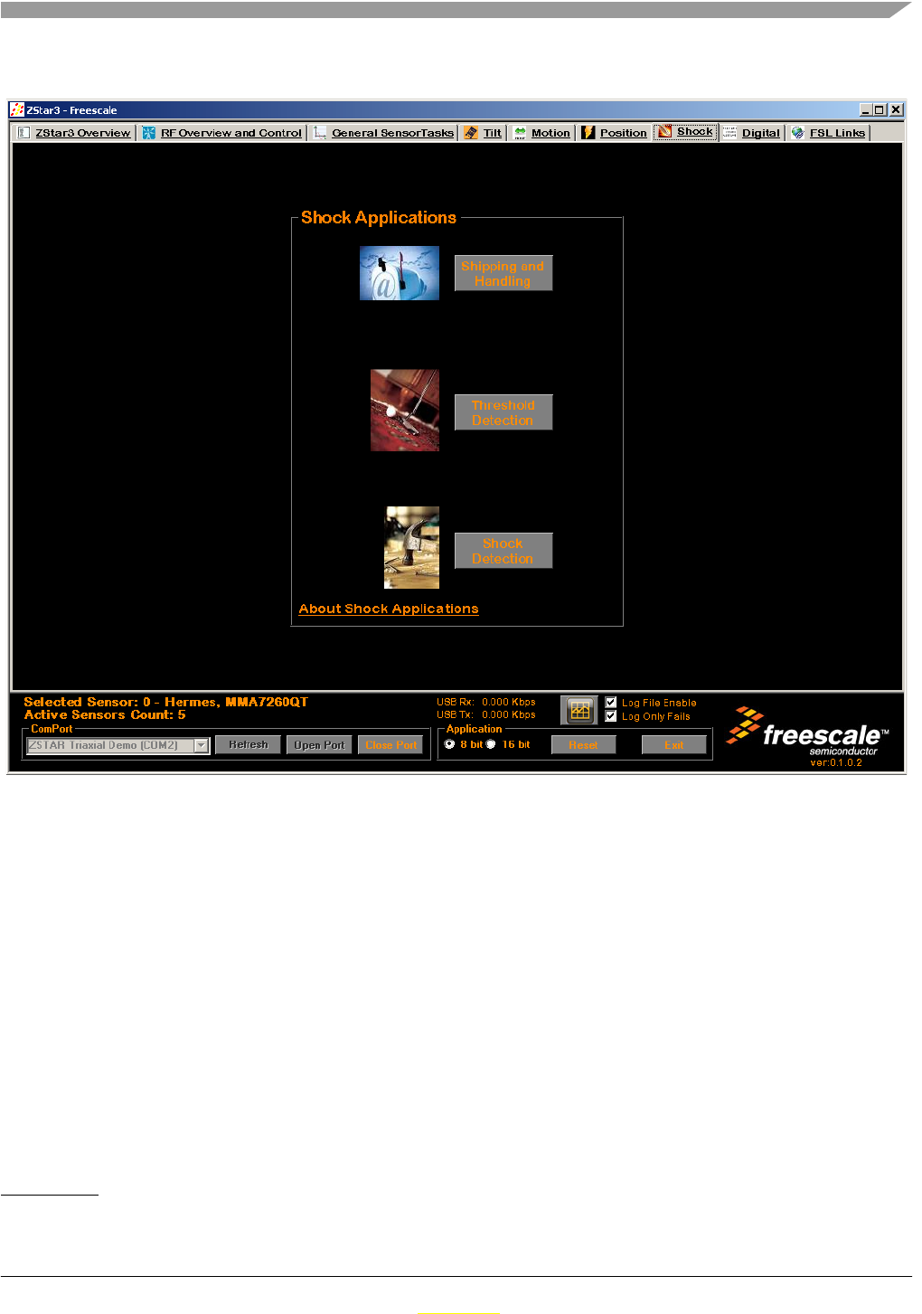
ZSTAR3 GUI
ZSTAR3 Reference Design Manual, Rev. 0.1
Freescale Semiconductor 7-73
Preliminary
Preliminary
7.2.9 Shock tasks
Figure 7-16. The Shock tasks screen.
The GUI Shock tasks controls1:
1. Shipping and handling screen - This demo shows how can used accelerometers in Shipping.
2. Treshold Detection screen - This window shows measuring of g treshold by accelerometers.
3. Shock Detection screen - This window shows measuring peaks of g by accelerometers.
4. About box - This about box content various information about Shock accelerometers applications.
1. Red numbers in picture marks individual controls described in list below.
1
2
3
4
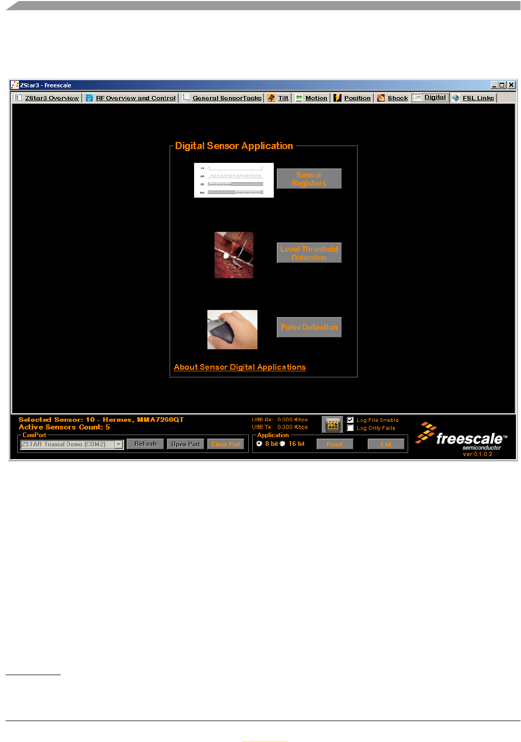
ZSTAR3 GUI
ZSTAR3 Reference Design Manual, Rev. 0.1
7-74 Freescale Semiconductor
Preliminary
Preliminary
7.2.10 Digital tasks
This tab contains specialy designed demos for Freescale digital accelerometer sensor(ION) MMA7450L.
Figure 7-17. The Digital tasks screen.
The GUI Digital tasks controls1:
1. Sensor registers screen - This demo shows all regisers inside of digital sensor in user friendly
format.
2. Level Treshold Detection screen - This window shows measuring of g treshold by digital
accelerometers.
3. Pulse Detection screen - This window shows measuring pulses of g by digital accelerometers.
4. About box - This about box content various information about Freescale digital accelerometers
applications.
1. Red numbers in picture marks individual controls described in list below.
1
2
3
4
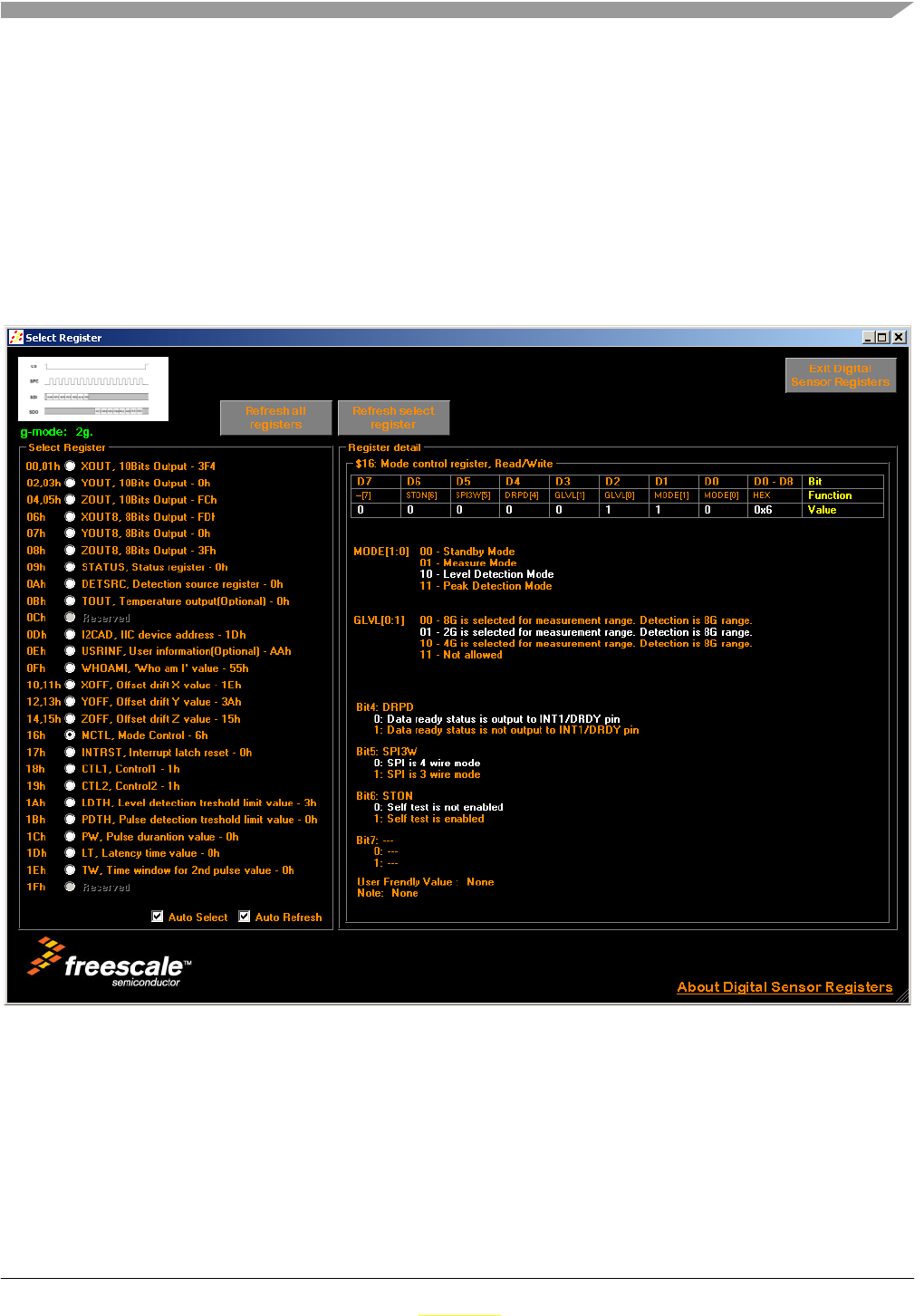
ZSTAR3 GUI
ZSTAR3 Reference Design Manual, Rev. 0.1
Freescale Semiconductor 7-75
Preliminary
Preliminary
7.2.10.1 Sensor registers demo application
This is specially designed window that shows all internal registers of MMA745xL accelerometer. It is
splited to two main parts:
• Left part contains list of all registers in MMA745xL accelerometer and its values in hex format. At
bottom of this panel are placed two check boxes. First is Auto Select option, that allow fast mode
selection of individual register, and second option allowed automaticaly refresh value of selected
register.
• Content of right part is depend on left one. It shows details of selected register in friendly format.
Active optins are displayed in white color.
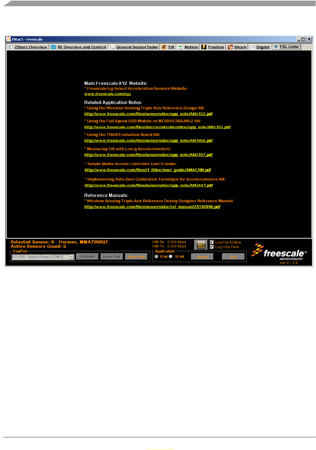
ZSTAR3 GUI
ZSTAR3 Reference Design Manual, Rev. 0.1
7-76 Freescale Semiconductor
Preliminary
Preliminary
7.2.11 Freescale Web Links.
Figure 7-18. The Links screen.
This screen contains couple of interesting links about Freescale and its accelerometric sensors.
7.3 The ZStar3 GUI Update USB Stick Software utility
The ZStar3 GUI can easily upgrade firmware in USb Stick by Bootloader capatibily. There are two
different ways how to start upgrade utility:
• Self-acting start - GUI always check software version of USB Stick with open port action. If it find
older version that it has, then GUI show information message with ask of start of software update
utility.
• Manual start - GUI can open direct registered Bootloader Com port.
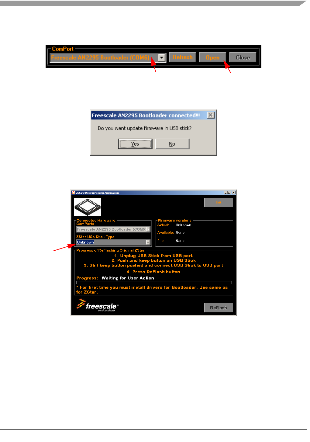
ZSTAR3 GUI
ZSTAR3 Reference Design Manual, Rev. 0.1
Freescale Semiconductor 7-77
Preliminary
Preliminary
7.3.1 Update process (Manual start)
1. For manual start select Bootloader Com port1 from Comport list and press Open button.
Figure 7-19. Update software procedure - step1
2. When the GUI show the a Information message box about Update procedure, click on OK button
to continue.
Figure 7-20. Update software procedure - step2
3. Now the GUI shows the Update window. On it it has to be selected right type of the currently
connected ZStar USB Stick.
Figure 7-21. Update software procedure - step3
1. Bootloader port is started by procedure described in Section 5.6.1, “Switch to Bootloader procedure.
Select right ComPort Then Open this port
Select type of
the USB Stick
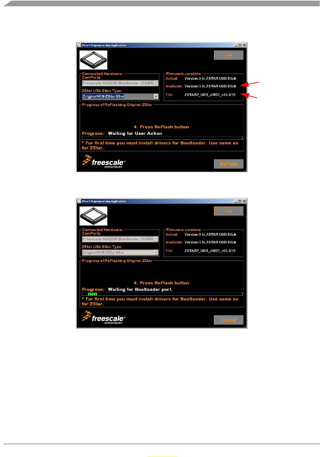
ZSTAR3 GUI
ZSTAR3 Reference Design Manual, Rev. 0.1
7-78 Freescale Semiconductor
Preliminary
Preliminary
4. When you select right type of USB Stick, the GUI know which files it has and offer latest version
of available software.
Figure 7-22. Update software procedure - step4
5. Now you can press ReFlash button. The GUI starts looking for a available Bootloader port.
Figure 7-23. Update software procedure - step5
Available version
File name of
available version
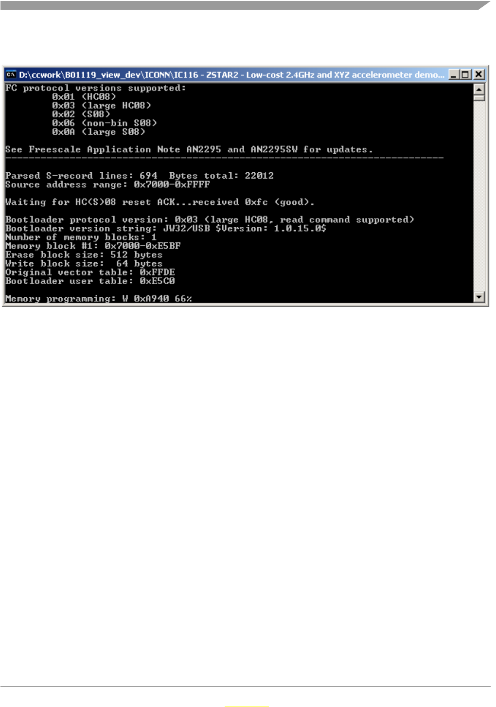
ZSTAR3 GUI
ZSTAR3 Reference Design Manual, Rev. 0.1
Freescale Semiconductor 7-79
Preliminary
Preliminary
6. When the GUI found a Bootloader port, the original bootload procedure starts. Please wait to end
of bootloader process.
Figure 7-24. Original bootloader application
When Update process finish success, close update window and enjoy all new features that brings new
version of the ZStar firmware.

ZSTAR3 GUI
ZSTAR3 Reference Design Manual, Rev. 0.1
7-80 Freescale Semiconductor
Preliminary
Preliminary

ZSTAR3 Reference Design Manual, Rev. 0.1
Freescale Semiconductor A-81
Preliminary
Preliminary
Appendix A
References
The following documents can be found on the Freescale web site: http://www.freescale.com.
1. AN2295 Application note - Developer’s Serial Bootloader for M68HC08 and HCS08 MCUs
2. AN3153 Application note - Using the Full-Speed USB Module on the MCHC908JW32
3. AN3447 Application note - Implementing Auto-Zero Calibration Techniquefor accelerometers
4. ZSTARRM Reference design manual - Original ZSTAR demo(RD3152MMA7260Q) RDM
5. MC9S08QG8 data sheet
6. MCHC908JW32 data sheet
7. MMA7260QTT data sheet
8. MMA7360LT data sheet
9. MMA7450L data sheet
10. MC13191 data sheet
11. MC13213 data sheet

References
ZSTAR3 Reference Design Manual, Rev. 0.1
A-82 Freescale Semiconductor
Preliminary
Preliminary