Freescale Semiconductor ZU Digital Data ZigBee Device User Manual Part 2
Freescale Semiconductor, Inc. Digital Data ZigBee Device Users Manual Part 2
UserManual.wiki
>
Freescale Semiconductor
>
ZU User Manual
>
Users Manual Part 2
Contents
1.
Users Manual Part 1
2.
Users Manual Part 2
Users Manual Part 2
Navigation menu
Upload a User Manual
Namespaces
Wiki Guide
HTML
PDF
Info
Views
User Manual
Discussion / Help
Navigation
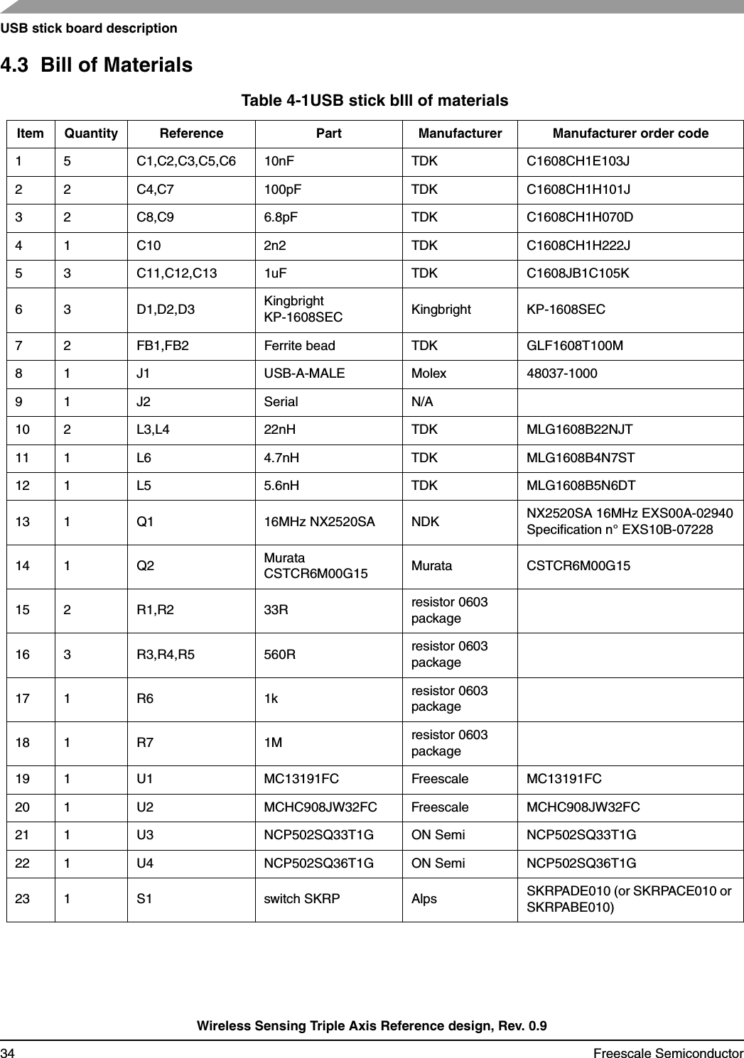
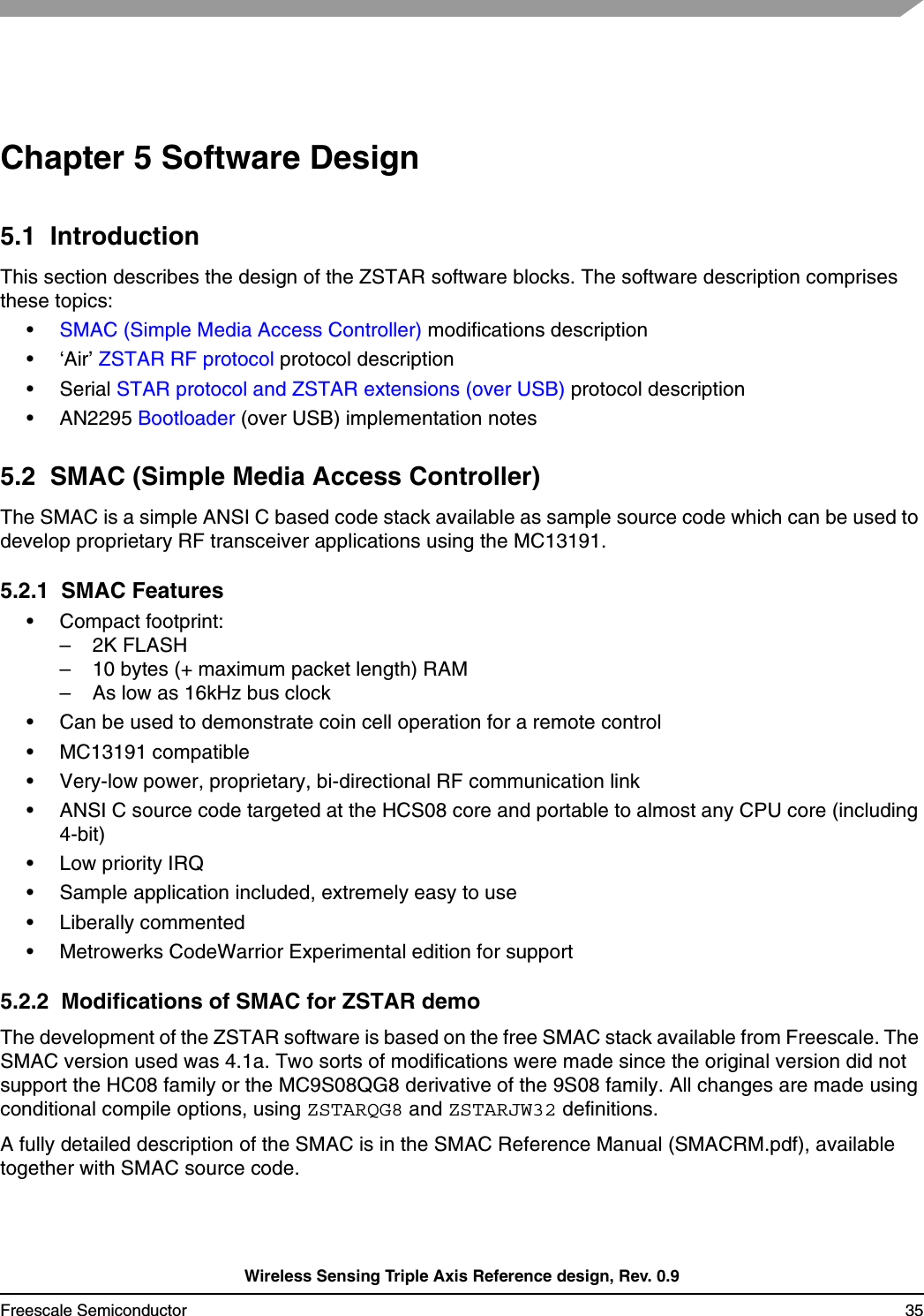
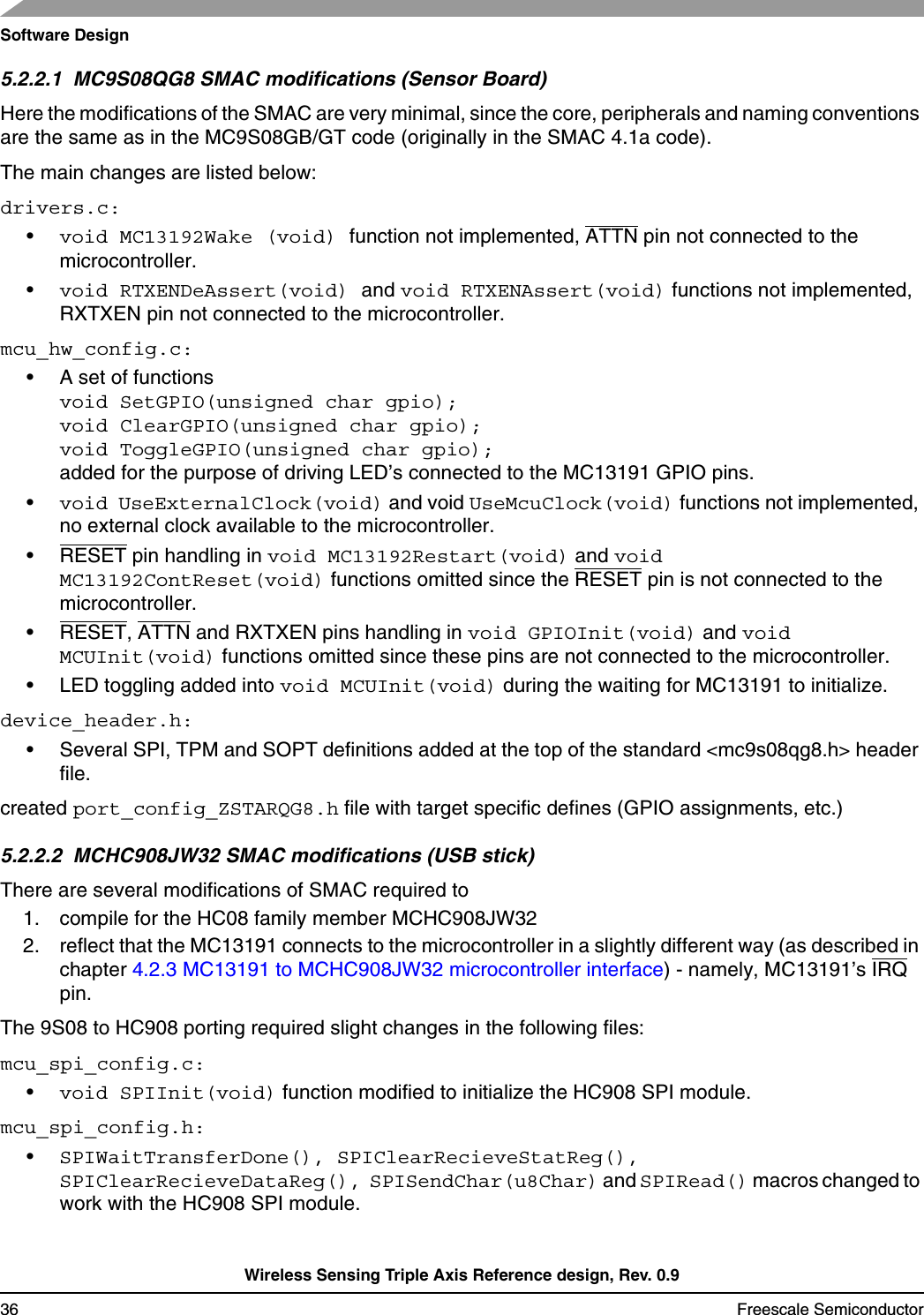
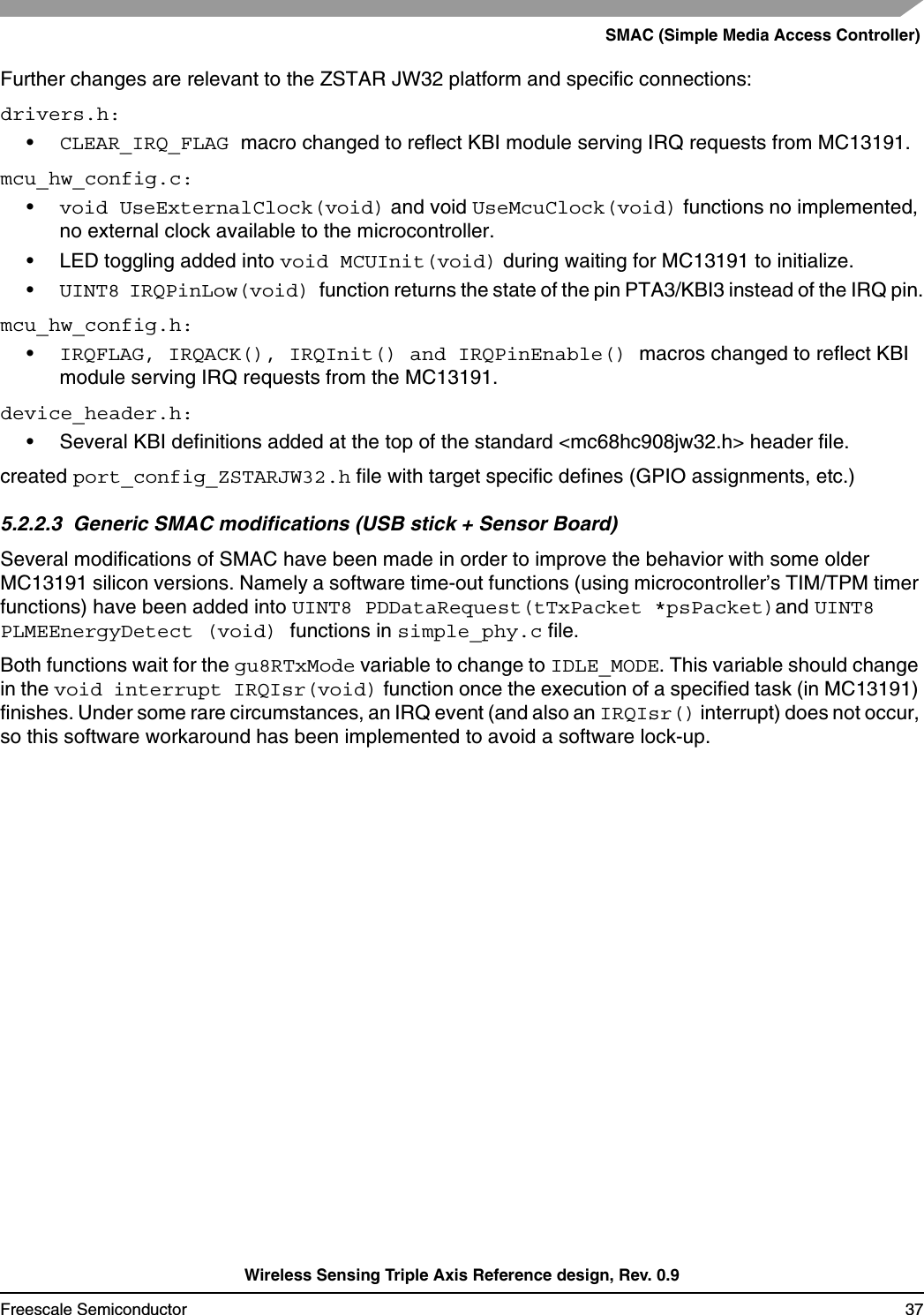
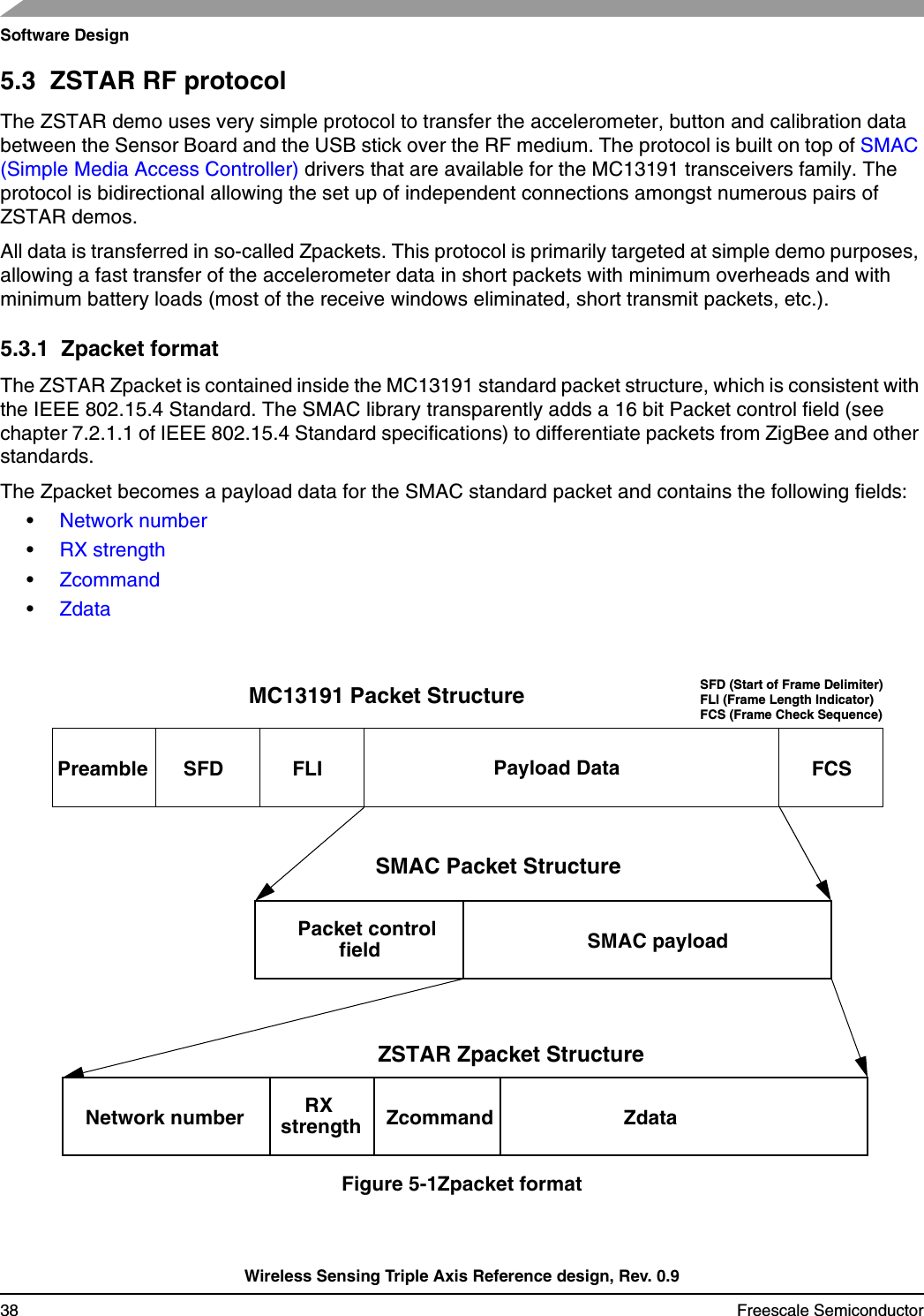
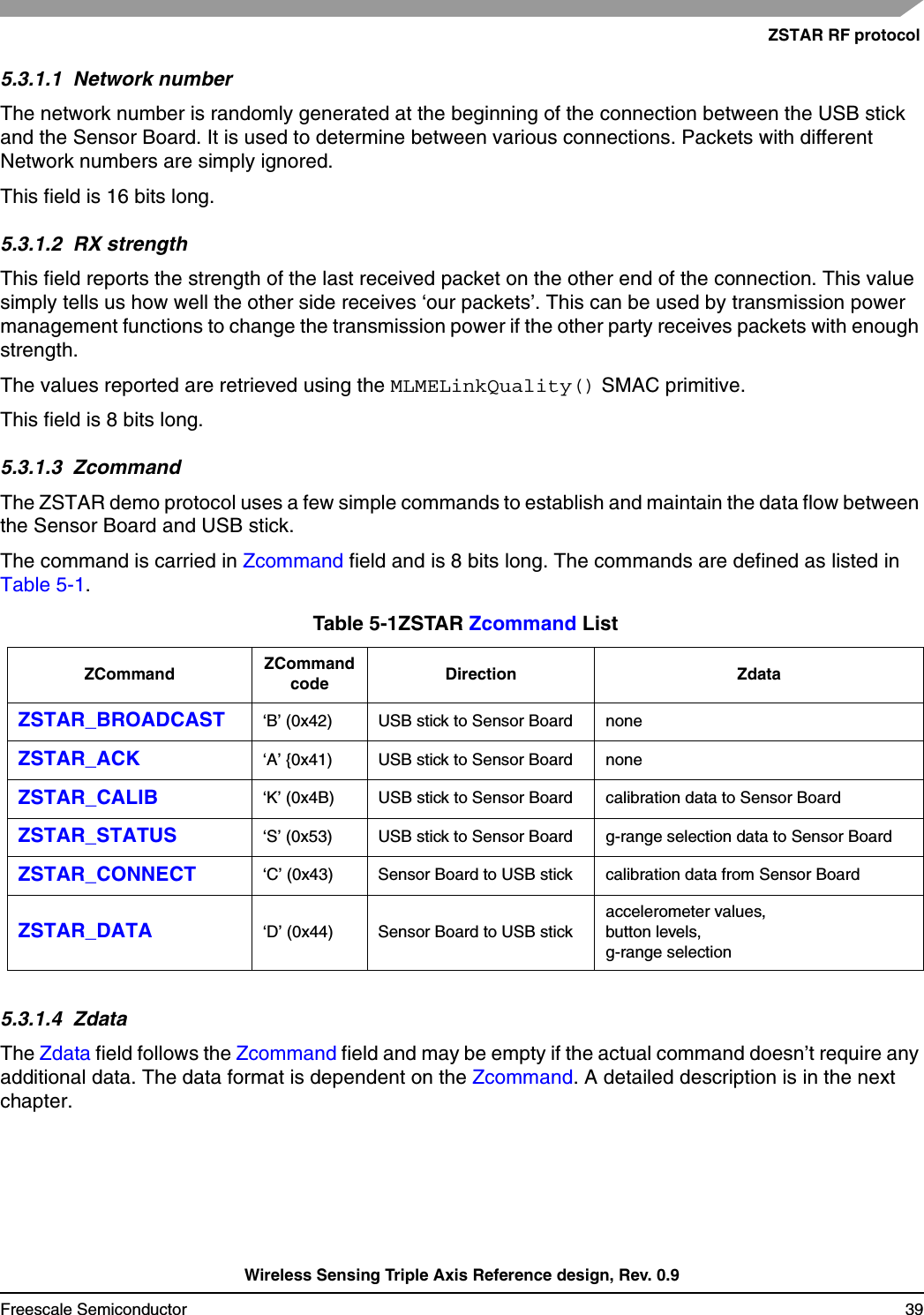
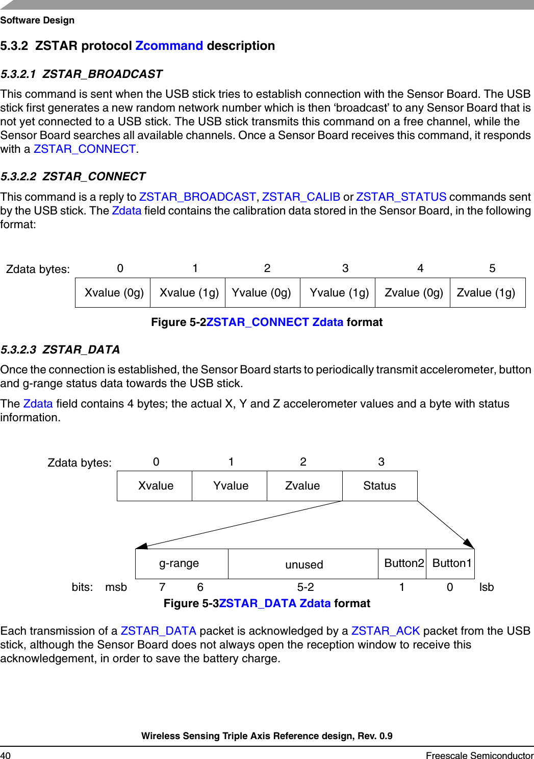
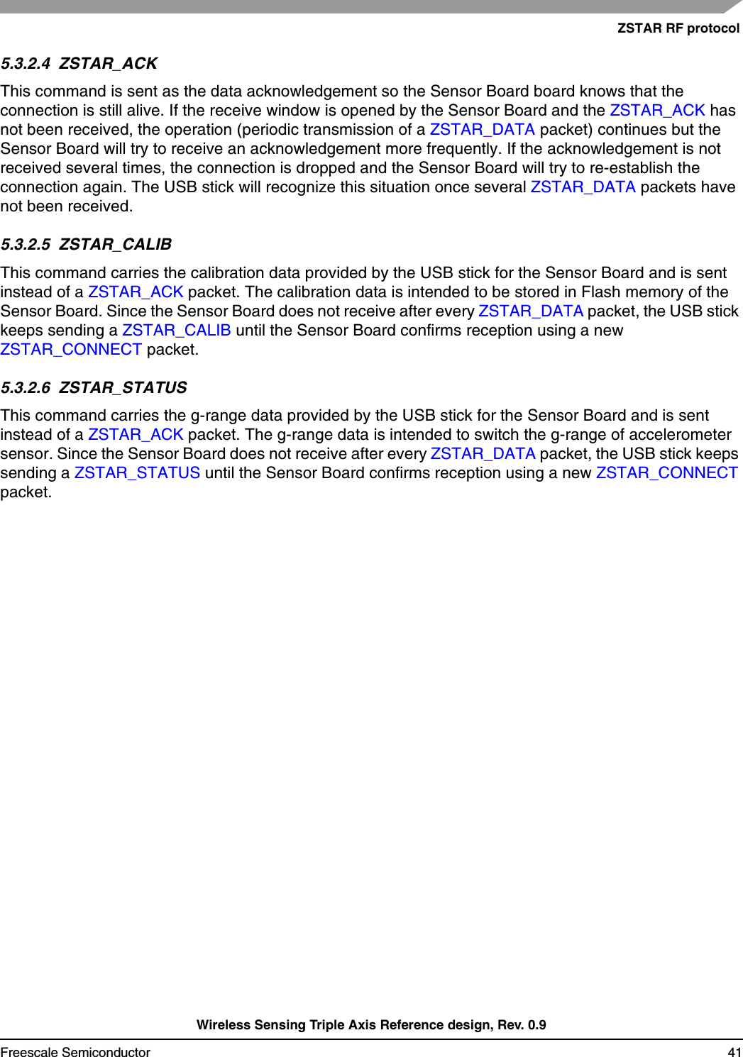
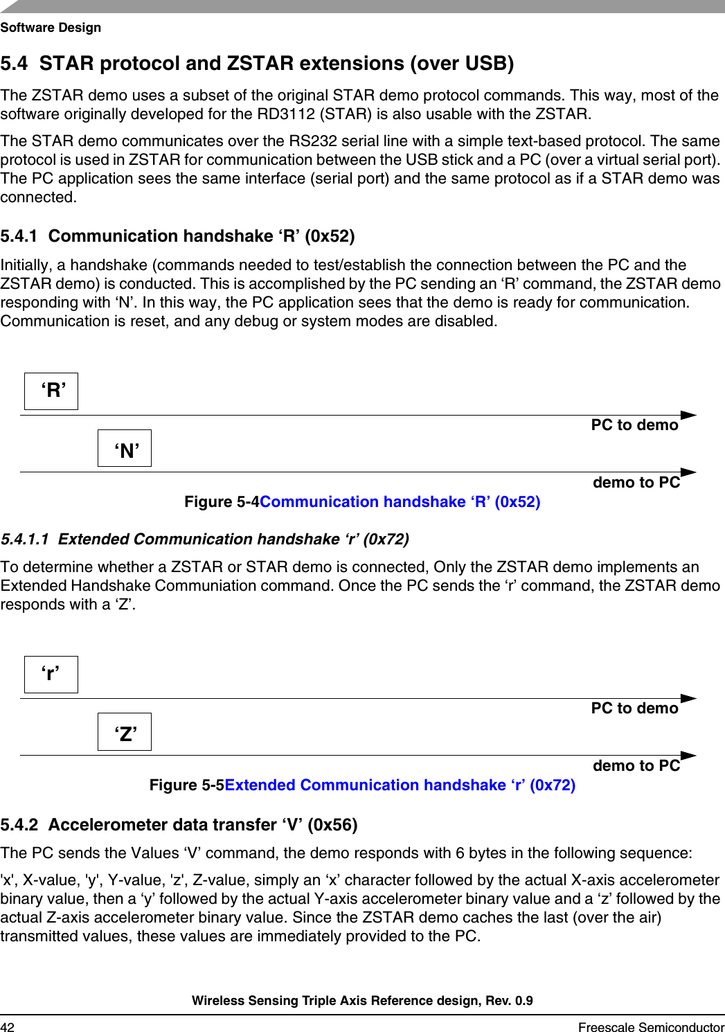
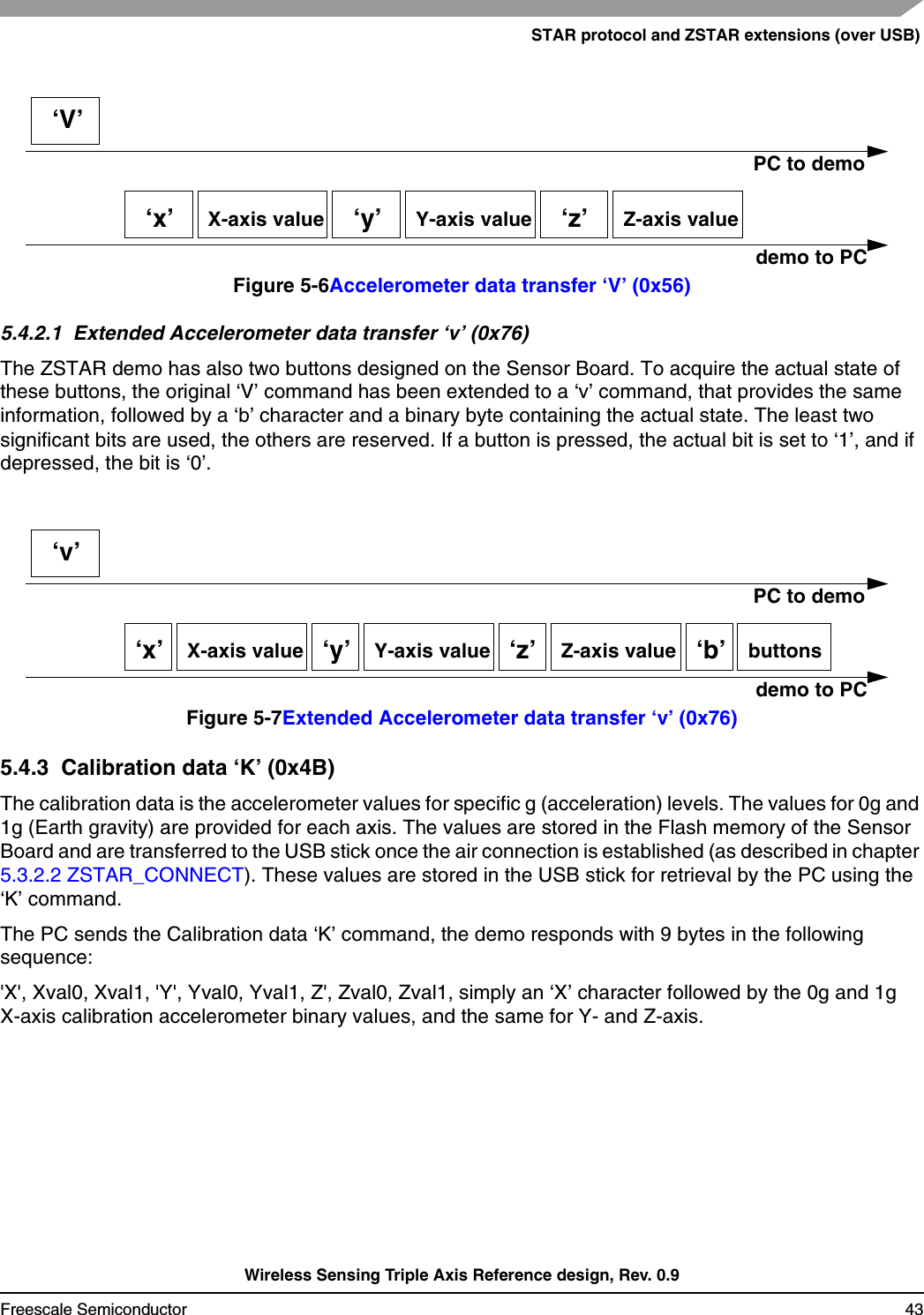
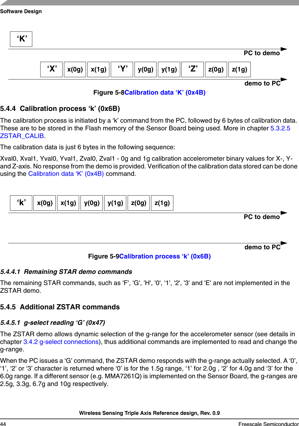
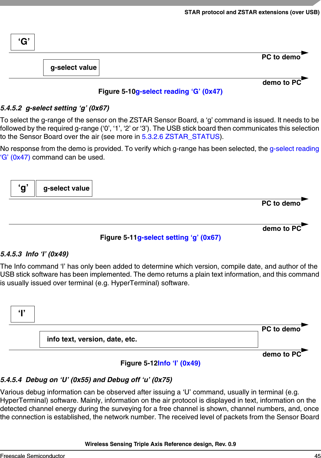
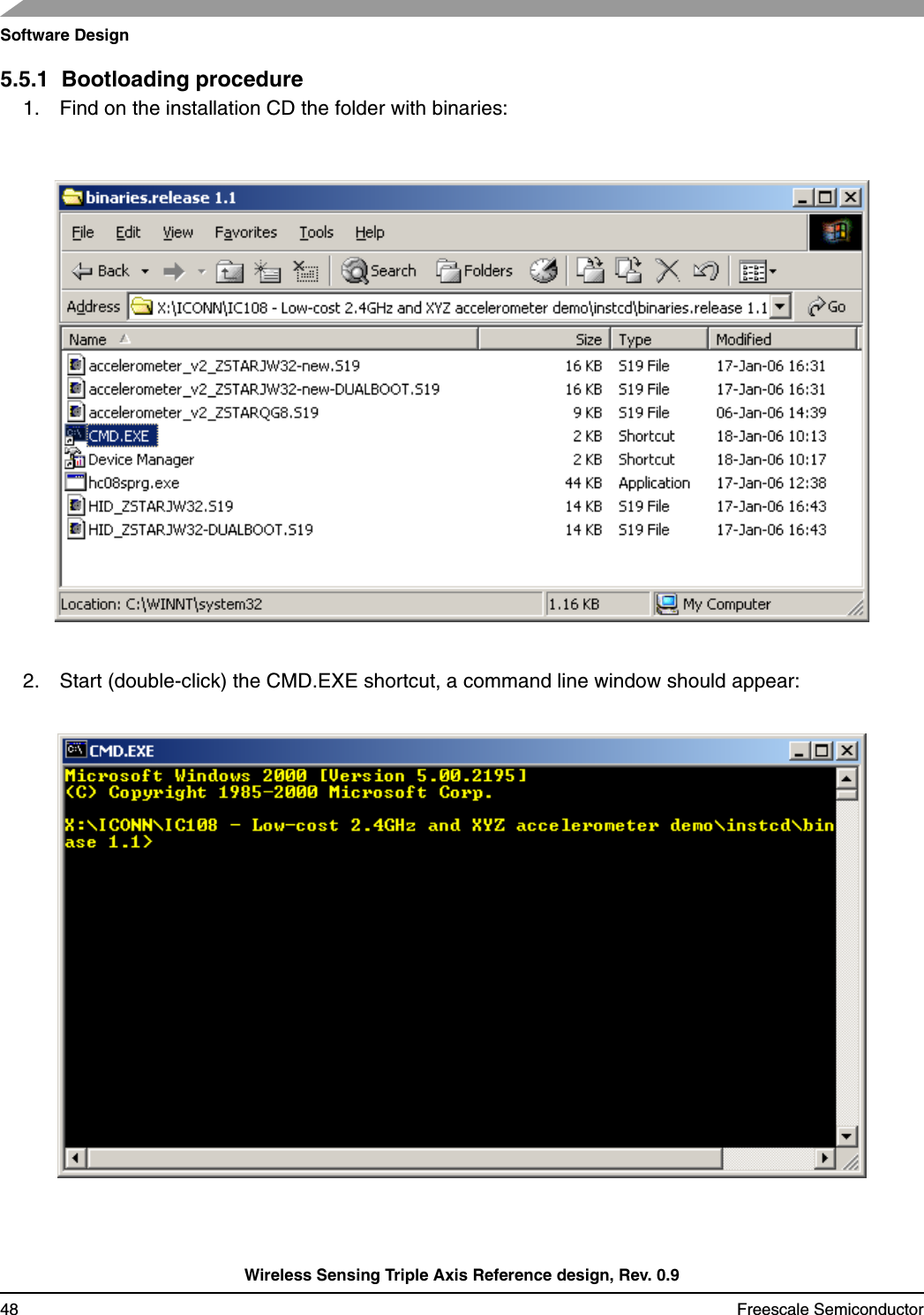
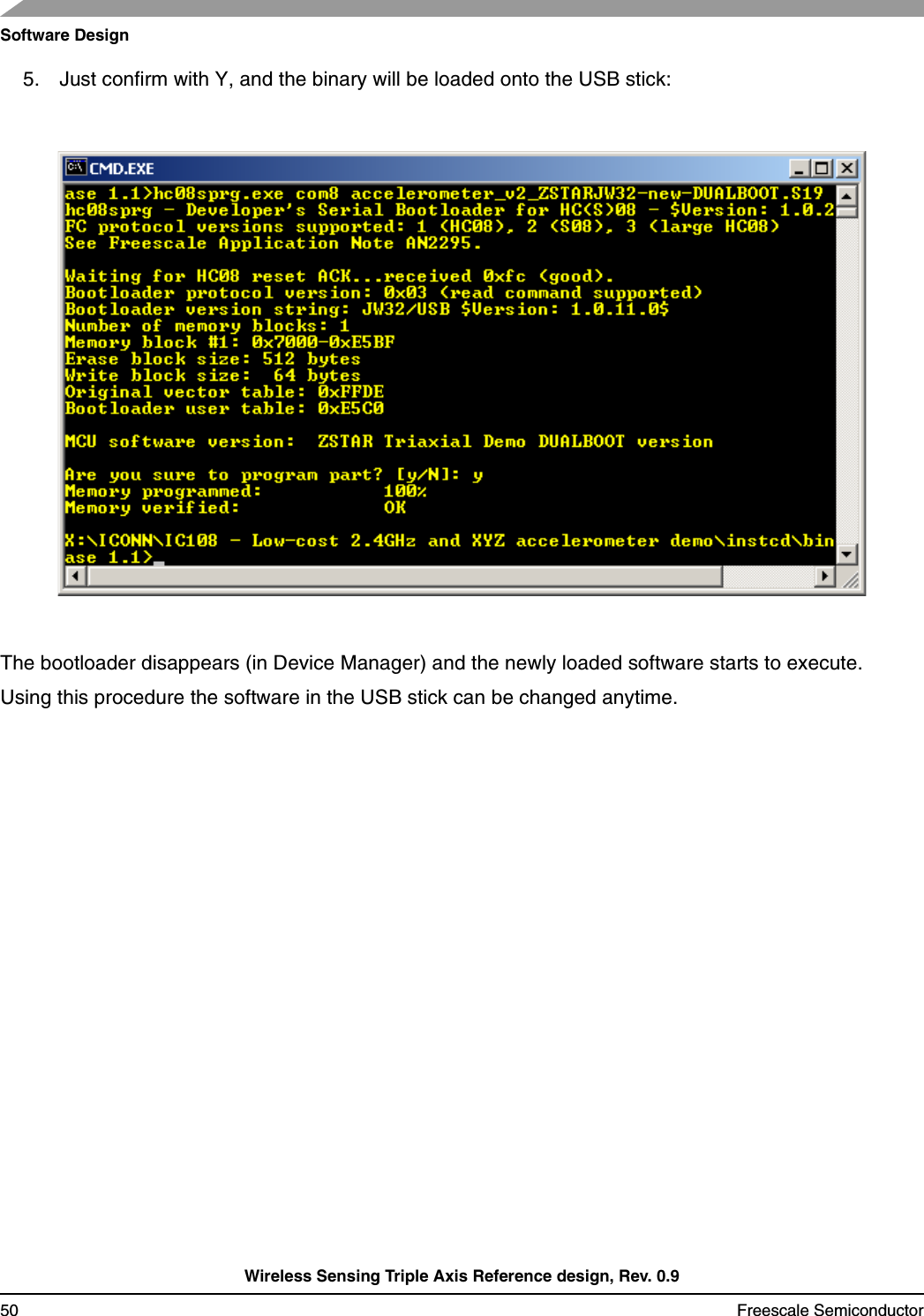
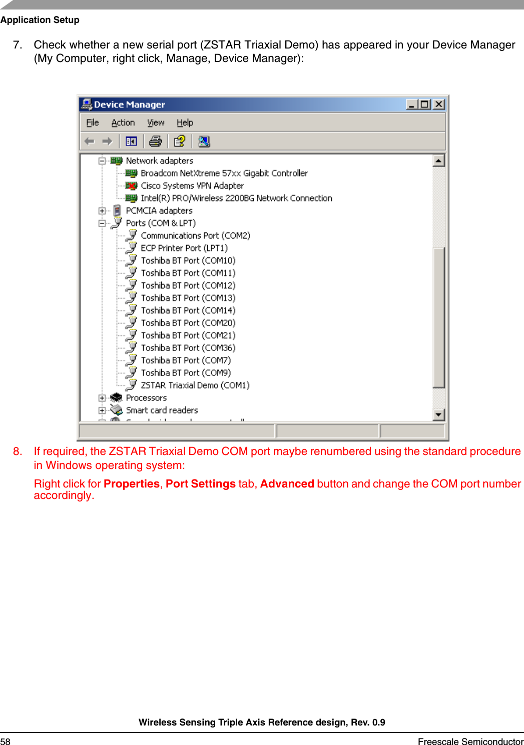
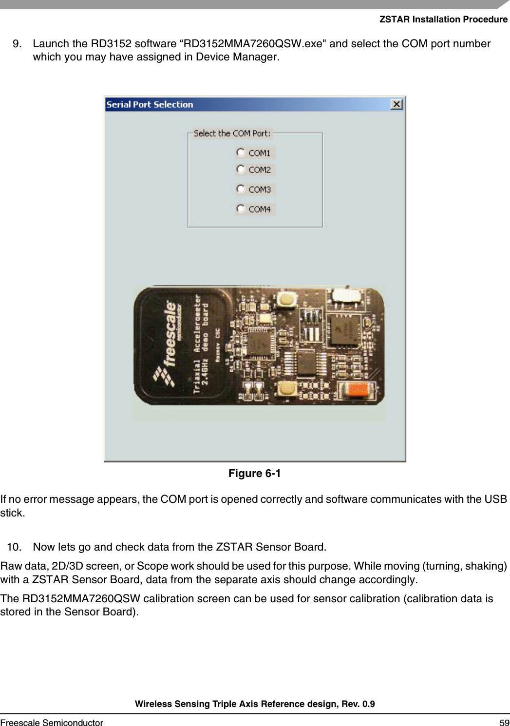
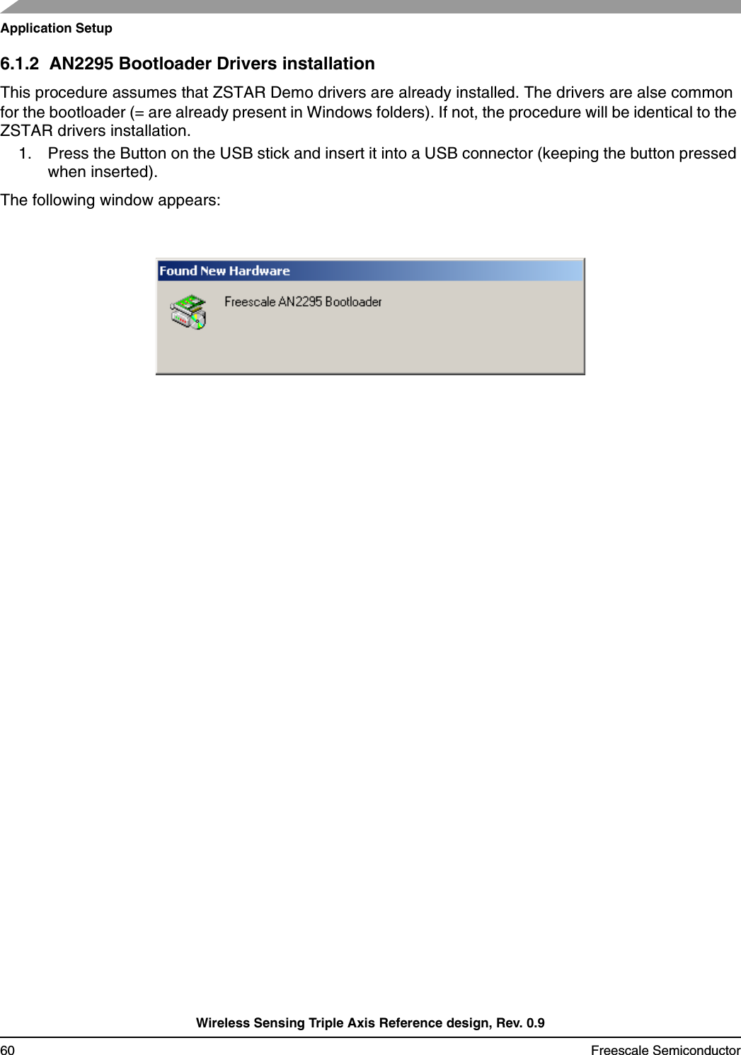
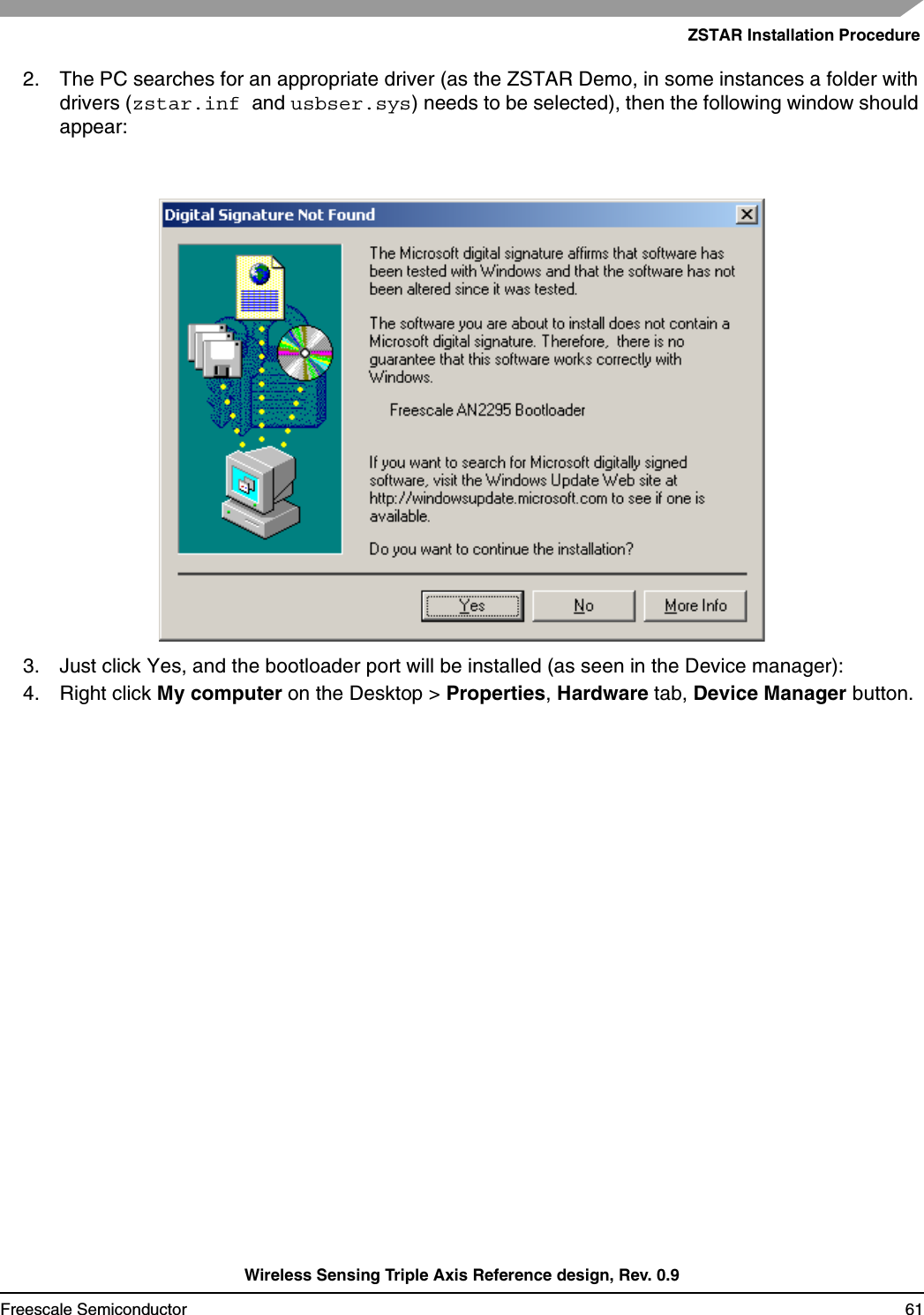
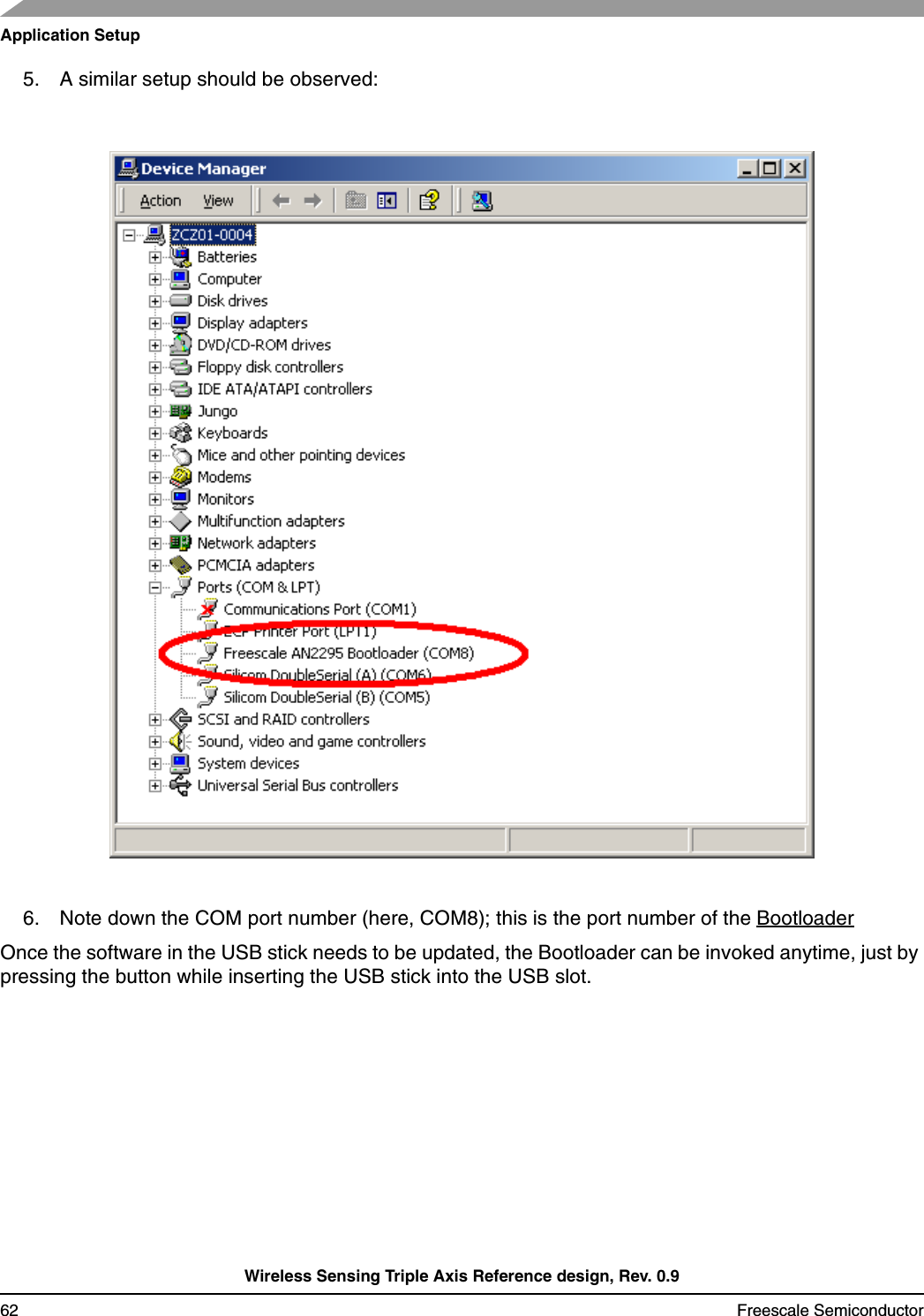
![BootloaderWireless Sensing Triple Axis Reference design, Rev. 0.9Freescale Semiconductor 493. Now type: hc08sprg [bootloader com port number] [binary (S file) that you want to bootload], just like this:hc08sprg.exe com8 accelerometer_v2_ZSTARJW32-new-DUALBOOT.S194. Press ENTER and initial bootloader communication will start:If this screen does not appear, remove the USB stick and start from the beginning.](https://usermanual.wiki/Freescale-Semiconductor/ZU.Users-Manual-Part-2/User-Guide-721802-Page-17.png)