Freescale Semiconductor ZU Digital Data ZigBee Device User Manual Part 2
Freescale Semiconductor, Inc. Digital Data ZigBee Device Users Manual Part 2
Contents
- 1. Users Manual Part 1
- 2. Users Manual Part 2
Users Manual Part 2
Wireless Sensing Triple Axis Reference design, Rev. 0.9
33 Freescale Semiconductor
USB stick board description
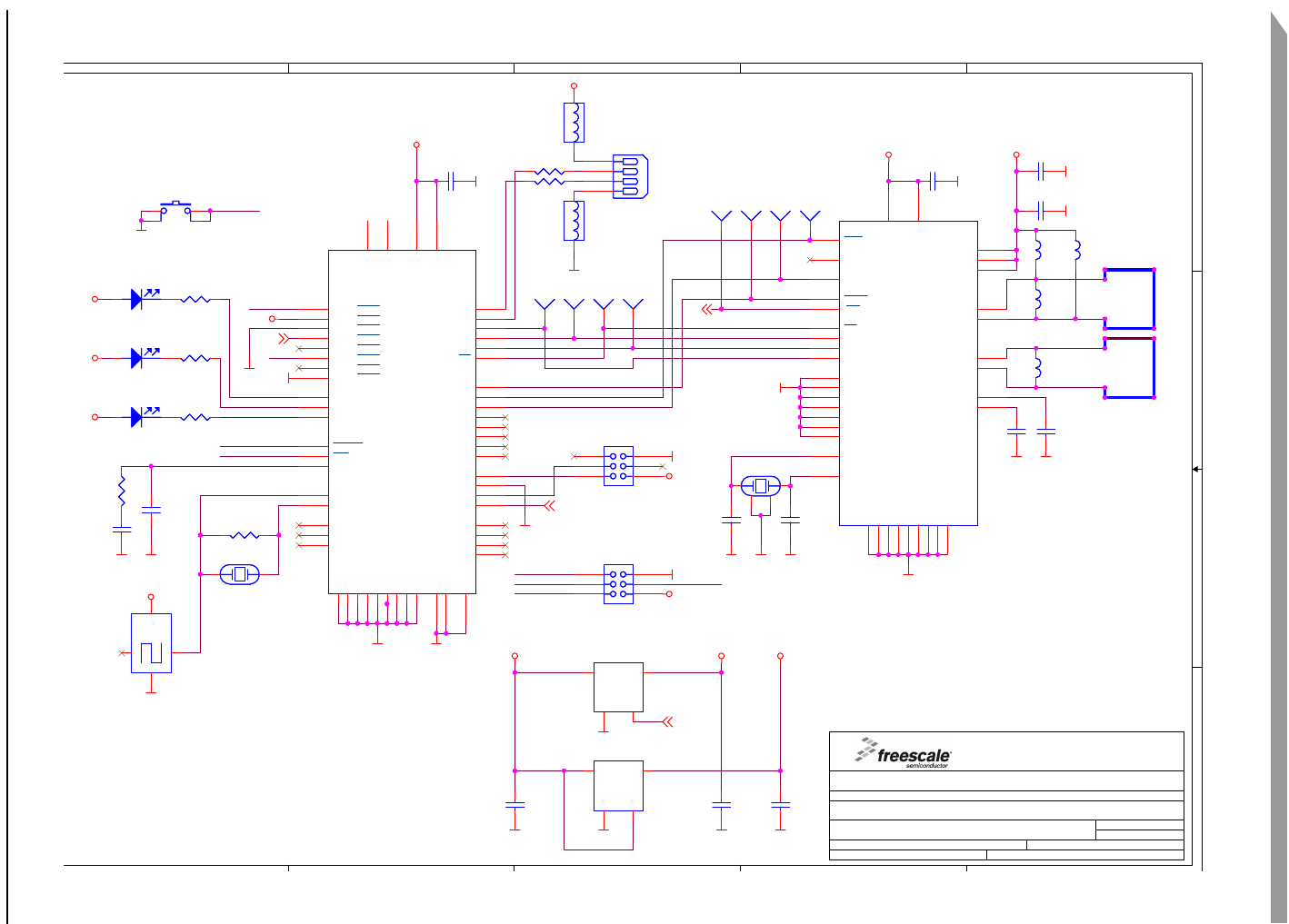
4.2.9 USB stick schematics
Figure 4-4USB stick schematics
5
5
4
4
3
3
2
2
1
1
D
C
B
A
TxD
RxD
PTA0
RxD
OSC1
MIRQ
MRESET
MIRQ
MRESET
MIRQ
OSC1
PTA0
GND
VDD36
GND
VDD33
GND
GND
GND GND
GND
GND
VDD
GND
VDD36
GND
VDDA
GND
GNDGND
VDD
GND
GND
VDD36
GNDGND
VDD33
GND
VDD36
GND
GND
GND
GND
VDD
VDD
VDD
GND
GND
VDD
GND
GND
GND
VDD36
GND
IRQ
VREG33EN
VREG33EN
IRQ
Title
Size
Design Name:
Rev
Modify Date: Sheet of
Schematic Name:
Copyright Freescale
POPI Status:
Author:
1.1
ZSTAR USB dongle
Freescale Semiconductor RCSC
1. maje 1009
756 61 Roznov p.R., Czech Republic, Europe
A4
1 1
Tuesday, August 08, 2006
SCHEMATIC1
General Business Information
Radomir Kozub & Pavel Lajsner
2005
X:\ICONN\IC108 - LOW-COST 2.4GHZ AND XYZ ACCELEROMETER DEMO\HW\00240\00240.DSN
C8
6.8pF
C8
6.8pF
C7
100pF
C7
100pF
L6
4.7nH
L6
4.7nH
R3 560R3 560
ATTNATTN
1
C1
10nF
C1
10nF
U4
NCP502SQ36T1G
U4
NCP502SQ36T1G
Vin
1Vout 5
GND
2
Enable
3
SPCLKSPCLK
1
L5
5.6nH
L5
5.6nH
R7
1M
R7
1M
C13
1uF
C13
1uF
S1
Alps SKRP
S1
Alps SKRP
1 3
42
Q2
Murata CSTCR6M00G53
Q2
Murata CSTCR6M00G53
12
L3
22nH
L3
22nH
R2 33RR2 33R
U2
MC68HC908JW32FC
U2
MC68HC908JW32FC
PTA0/KBA0
1
NC 2
NC 3
PTC1/TCLK1 4
PTC3 5
PTB5
6
PTC0/T1CH0 7
PTE7/SS 8
PTE6/MISO 9
PTE5/MOSI 10
PTE4/SPCLK 11
NC 12
PTD0 13
PTD1 14
PTD2 15
PTD3 16
PTD4 17
PTD5 18
PTD6 19
NC
21
PTD7 22
NC
23
NC
24
OSC1
25
OSC2
26
PTB0
27
PTB1
28
VSS33
29
PTE2/PS2CLK/D+ 30
PTE3/D- 31
REG33V 32
VSSPLL
33
CGMXFC
34
VDDPLL 35
PTA7/KBA7
36
RESET
37
IRQ
38
PTA6/KBA6
39 PTA5/KBA5
40
PTC2/T1CH1 41
VDD 42
REG25V 43
VSS
44
PTA4/KBA4
45 PTA3/KBA3
46 PTA2/KBA2
47 PTA1/KBA1
48
NC 20
EPGND
100 EPGND
101 EPGND
102 EPGND
103 EPGND
104 EPGND
105 EPGND
106 EPGND
107 EPGND
108
C4
100pF
C4
100pF
MOSIMOSI
1
D1
LED
D1
LED
C11
1uF
C11
1uF
C10
2n2
C10
2n2
FB1
BEAD
FB1
BEAD
12
J3
uMON08
J3
uMON08
1 2
3 4
65
D3
LED
D3
LED
RTXENRTXEN
1
L4
22nH
L4
22nH
OSC.
Q3
EPSON-SG310 4.0MHz
OSC.
Q3
EPSON-SG310 4.0MHz
3
2 4
1
D2
LED
D2
LED
U1
MC13191FC
U1
MC13191FC
RFIN- 1
RFIN+ 2
PAO+ 5
PAO- 6
GPIO4
8GPIO3
9GPIO2
10 GPIO1
11
RST
12
RXTXEN
13
ATTN
14
CLKO
15
SPICLK
16
MOSI
17
MISO
18
CE
19
IRQ
20
VDDD 21
VDDINT 22
GPIO5
23
GPIO6
24
GPIO7
25
CRYSTAL1
26
CRYSTAL2
27
VDDLO2 28
VDDLO1 29
VDDVCO 30
VBATT 31
VDDA 32
EPGND
36 EPGND
37 EPGND
38 EPGND
39 EPGND
40 EPGND
41
EPGND
35
EPGND
34
EPGND
33
R1 33RR1 33R
SSSS
1
J1
USB-A-MALE
J1
USB-A-MALE
2
1
3
4
C3
10nF
C3
10nF
Q1
16MHz NX2520SA
Q1
16MHz NX2520SA
12
3
4
R5 560R5 560
IRQIRQ
1
R6
1k
R6
1k
C12
1uF
C12
1uF
FB2
BEAD
FB2
BEAD
12
R4 560R4 560
C6
10nF
C6
10nF
C2
10nF
C2
10nF
U3
NCP502SQ33T1G
U3
NCP502SQ33T1G
Vin
1Vout 5
GND
2
Enable
3
J2
Serial
J2
Serial
1 2
3 4
65
RSTRST
1
C9
6.8pF
C9
6.8pF
MISOMISO
1
C5
10nF
C5
10nF

USB stick board description
Wireless Sensing Triple Axis Reference design, Rev. 0.9
34 Freescale Semiconductor
4.3 Bill of Materials
Table 4-1USB stick bIll of materials
Item Quantity Reference Part Manufacturer Manufacturer order code
1 5 C1,C2,C3,C5,C6 10nF TDK C1608CH1E103J
2 2 C4,C7 100pF TDK C1608CH1H101J
3 2 C8,C9 6.8pF TDK C1608CH1H070D
4 1 C10 2n2 TDK C1608CH1H222J
5 3 C11,C12,C13 1uF TDK C1608JB1C105K
6 3 D1,D2,D3 Kingbright
KP-1608SEC Kingbright KP-1608SEC
7 2 FB1,FB2 Ferrite bead TDK GLF1608T100M
8 1 J1 USB-A-MALE Molex 48037-1000
9 1 J2 Serial N/A
10 2 L3,L4 22nH TDK MLG1608B22NJT
11 1 L6 4.7nH TDK MLG1608B4N7ST
12 1 L5 5.6nH TDK MLG1608B5N6DT
13 1 Q1 16MHz NX2520SA NDK NX2520SA 16MHz EXS00A-02940
Specification n° EXS10B-07228
14 1 Q2 Murata
CSTCR6M00G15 Murata CSTCR6M00G15
15 2 R1,R2 33R resistor 0603
package
16 3 R3,R4,R5 560R resistor 0603
package
17 1 R6 1k resistor 0603
package
18 1 R7 1M resistor 0603
package
19 1 U1 MC13191FC Freescale MC13191FC
20 1 U2 MCHC908JW32FC Freescale MCHC908JW32FC
21 1 U3 NCP502SQ33T1G ON Semi NCP502SQ33T1G
22 1 U4 NCP502SQ36T1G ON Semi NCP502SQ36T1G
23 1 S1 switch SKRP Alps SKRPADE010 (or SKRPACE010 or
SKRPABE010)

Wireless Sensing Triple Axis Reference design, Rev. 0.9
Freescale Semiconductor 35
Chapter 5 Software Design
5.1 Introduction
This section describes the design of the ZSTAR software blocks. The software description comprises
these topics:
•SMAC (Simple Media Access Controller) modifications description
• ‘Air’ ZSTAR RF protocol protocol description
• Serial STAR protocol and ZSTAR extensions (over USB) protocol description
• AN2295 Bootloader (over USB) implementation notes
5.2 SMAC (Simple Media Access Controller)
The SMAC is a simple ANSI C based code stack available as sample source code which can be used to
develop proprietary RF transceiver applications using the MC13191.
5.2.1 SMAC Features
• Compact footprint:
– 2K FLASH
– 10 bytes (+ maximum packet length) RAM
– As low as 16kHz bus clock
• Can be used to demonstrate coin cell operation for a remote control
• MC13191 compatible
• Very-low power, proprietary, bi-directional RF communication link
• ANSI C source code targeted at the HCS08 core and portable to almost any CPU core (including
4-bit)
• Low priority IRQ
• Sample application included, extremely easy to use
• Liberally commented
• Metrowerks CodeWarrior Experimental edition for support
5.2.2 Modifications of SMAC for ZSTAR demo
The development of the ZSTAR software is based on the free SMAC stack available from Freescale. The
SMAC version used was 4.1a. Two sorts of modifications were made since the original version did not
support the HC08 family or the MC9S08QG8 derivative of the 9S08 family. All changes are made using
conditional compile options, using ZSTARQG8 and ZSTARJW32 definitions.
A fully detailed description of the SMAC is in the SMAC Reference Manual (SMACRM.pdf), available
together with SMAC source code.

Software Design
Wireless Sensing Triple Axis Reference design, Rev. 0.9
36 Freescale Semiconductor
5.2.2.1 MC9S08QG8 SMAC modifications (Sensor Board)
Here the modifications of the SMAC are very minimal, since the core, peripherals and naming conventions
are the same as in the MC9S08GB/GT code (originally in the SMAC 4.1a code).
The main changes are listed below:
drivers.c:
•void MC13192Wake (void) function not implemented, ATTN pin not connected to the
microcontroller.
•void RTXENDeAssert(void) and void RTXENAssert(void) functions not implemented,
RXTXEN pin not connected to the microcontroller.
mcu_hw_config.c:
• A set of functions
void SetGPIO(unsigned char gpio);
void ClearGPIO(unsigned char gpio);
void ToggleGPIO(unsigned char gpio);
added for the purpose of driving LED’s connected to the MC13191 GPIO pins.
•void UseExternalClock(void) and void UseMcuClock(void) functions not implemented,
no external clock available to the microcontroller.
• RESET pin handling in void MC13192Restart(void) and void
MC13192ContReset(void) functions omitted since the RESET pin is not connected to the
microcontroller.
• RESET, ATTN and RXTXEN pins handling in void GPIOInit(void) and void
MCUInit(void) functions omitted since these pins are not connected to the microcontroller.
• LED toggling added into void MCUInit(void) during the waiting for MC13191 to initialize.
device_header.h:
• Several SPI, TPM and SOPT definitions added at the top of the standard <mc9s08qg8.h> header
file.
created port_config_ZSTARQG8.h file with target specific defines (GPIO assignments, etc.)
5.2.2.2 MCHC908JW32 SMAC modifications (USB stick)
There are several modifications of SMAC required to
1. compile for the HC08 family member MCHC908JW32
2. reflect that the MC13191 connects to the microcontroller in a slightly different way (as described in
chapter 4.2.3 MC13191 to MCHC908JW32 microcontroller interface) - namely, MC13191’s IRQ
pin.
The 9S08 to HC908 porting required slight changes in the following files:
mcu_spi_config.c:
•void SPIInit(void) function modified to initialize the HC908 SPI module.
mcu_spi_config.h:
•SPIWaitTransferDone(), SPIClearRecieveStatReg(),
SPIClearRecieveDataReg(), SPISendChar(u8Char) and SPIRead() macros changed to
work with the HC908 SPI module.

SMAC (Simple Media Access Controller)
Wireless Sensing Triple Axis Reference design, Rev. 0.9
Freescale Semiconductor 37
Further changes are relevant to the ZSTAR JW32 platform and specific connections:
drivers.h:
•CLEAR_IRQ_FLAG macro changed to reflect KBI module serving IRQ requests from MC13191.
mcu_hw_config.c:
•void UseExternalClock(void) and void UseMcuClock(void) functions no implemented,
no external clock available to the microcontroller.
• LED toggling added into void MCUInit(void) during waiting for MC13191 to initialize.
•UINT8 IRQPinLow(void) function returns the state of the pin PTA3/KBI3 instead of the IRQ pin.
mcu_hw_config.h:
•IRQFLAG, IRQACK(), IRQInit() and IRQPinEnable() macros changed to reflect KBI
module serving IRQ requests from the MC13191.
device_header.h:
• Several KBI definitions added at the top of the standard <mc68hc908jw32.h> header file.
created port_config_ZSTARJW32.h file with target specific defines (GPIO assignments, etc.)
5.2.2.3 Generic SMAC modifications (USB stick + Sensor Board)
Several modifications of SMAC have been made in order to improve the behavior with some older
MC13191 silicon versions. Namely a software time-out functions (using microcontroller’s TIM/TPM timer
functions) have been added into UINT8 PDDataRequest(tTxPacket *psPacket)and UINT8
PLMEEnergyDetect (void) functions in simple_phy.c file.
Both functions wait for the gu8RTxMode variable to change to IDLE_MODE. This variable should change
in the void interrupt IRQIsr(void) function once the execution of a specified task (in MC13191)
finishes. Under some rare circumstances, an IRQ event (and also an IRQIsr() interrupt) does not occur,
so this software workaround has been implemented to avoid a software lock-up.
Software Design
Wireless Sensing Triple Axis Reference design, Rev. 0.9
38 Freescale Semiconductor
5.3 ZSTAR RF protocol
The ZSTAR demo uses very simple protocol to transfer the accelerometer, button and calibration data
between the Sensor Board and the USB stick over the RF medium. The protocol is built on top of SMAC
(Simple Media Access Controller) drivers that are available for the MC13191 transceivers family. The
protocol is bidirectional allowing the set up of independent connections amongst numerous pairs of
ZSTAR demos.
All data is transferred in so-called Zpackets. This protocol is primarily targeted at simple demo purposes,
allowing a fast transfer of the accelerometer data in short packets with minimum overheads and with
minimum battery loads (most of the receive windows eliminated, short transmit packets, etc.).
5.3.1 Zpacket format
The ZSTAR Zpacket is contained inside the MC13191 standard packet structure, which is consistent with
the IEEE 802.15.4 Standard. The SMAC library transparently adds a 16 bit Packet control field (see
chapter 7.2.1.1 of IEEE 802.15.4 Standard specifications) to differentiate packets from ZigBee and other
standards.
The Zpacket becomes a payload data for the SMAC standard packet and contains the following fields:
•Network number
•RX strength
•Zcommand
•Zdata
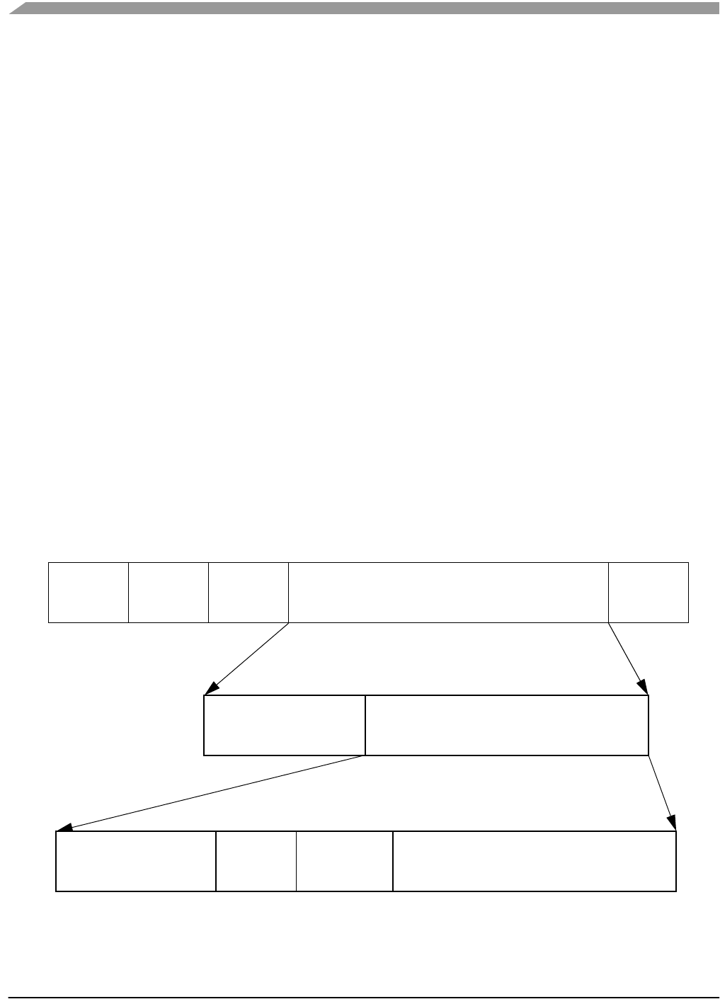
Figure 5-1Zpacket format
Preamble SFD FLI Payload Data FCS
MC13191 Packet Structure SFD (Start of Frame Delimiter)
FLI (Frame Length Indicator)
FCS (Frame Check Sequence)
Network number RX
strength Zcommand Zdata
ZSTAR Zpacket Structure
Packet control SMAC payload
SMAC Packet Structure
field

ZSTAR RF protocol
Wireless Sensing Triple Axis Reference design, Rev. 0.9
Freescale Semiconductor 39
5.3.1.1 Network number
The network number is randomly generated at the beginning of the connection between the USB stick
and the Sensor Board. It is used to determine between various connections. Packets with different
Network numbers are simply ignored.
This field is 16 bits long.
5.3.1.2 RX strength
This field reports the strength of the last received packet on the other end of the connection. This value
simply tells us how well the other side receives ‘our packets’. This can be used by transmission power
management functions to change the transmission power if the other party receives packets with enough
strength.
The values reported are retrieved using the MLMELinkQuality() SMAC primitive.
This field is 8 bits long.
5.3.1.3 Zcommand
The ZSTAR demo protocol uses a few simple commands to establish and maintain the data flow between
the Sensor Board and USB stick.
The command is carried in Zcommand field and is 8 bits long. The commands are defined as listed in
Table 5-1.
5.3.1.4 Zdata
The Zdata field follows the Zcommand field and may be empty if the actual command doesn’t require any
additional data. The data format is dependent on the Zcommand. A detailed description is in the next
chapter.
Table 5-1ZSTAR Zcommand List
ZCommand ZCommand
code Direction Zdata
ZSTAR_BROADCAST ‘B’ (0x42) USB stick to Sensor Board none
ZSTAR_ACK ‘A’ {0x41) USB stick to Sensor Board none
ZSTAR_CALIB ‘K’ (0x4B) USB stick to Sensor Board calibration data to Sensor Board
ZSTAR_STATUS ‘S’ (0x53) USB stick to Sensor Board g-range selection data to Sensor Board
ZSTAR_CONNECT ‘C’ (0x43) Sensor Board to USB stick calibration data from Sensor Board
ZSTAR_DATA ‘D’ (0x44) Sensor Board to USB stick
accelerometer values,
button levels,
g-range selection
Software Design
Wireless Sensing Triple Axis Reference design, Rev. 0.9
40 Freescale Semiconductor
5.3.2 ZSTAR protocol Zcommand description
5.3.2.1 ZSTAR_BROADCAST
This command is sent when the USB stick tries to establish connection with the Sensor Board. The USB
stick first generates a new random network number which is then ‘broadcast’ to any Sensor Board that is
not yet connected to a USB stick. The USB stick transmits this command on a free channel, while the
Sensor Board searches all available channels. Once a Sensor Board receives this command, it responds
with a ZSTAR_CONNECT.
5.3.2.2 ZSTAR_CONNECT
This command is a reply to ZSTAR_BROADCAST,ZSTAR_CALIB or ZSTAR_STATUS commands sent
by the USB stick. The Zdata field contains the calibration data stored in the Sensor Board, in the following
format:
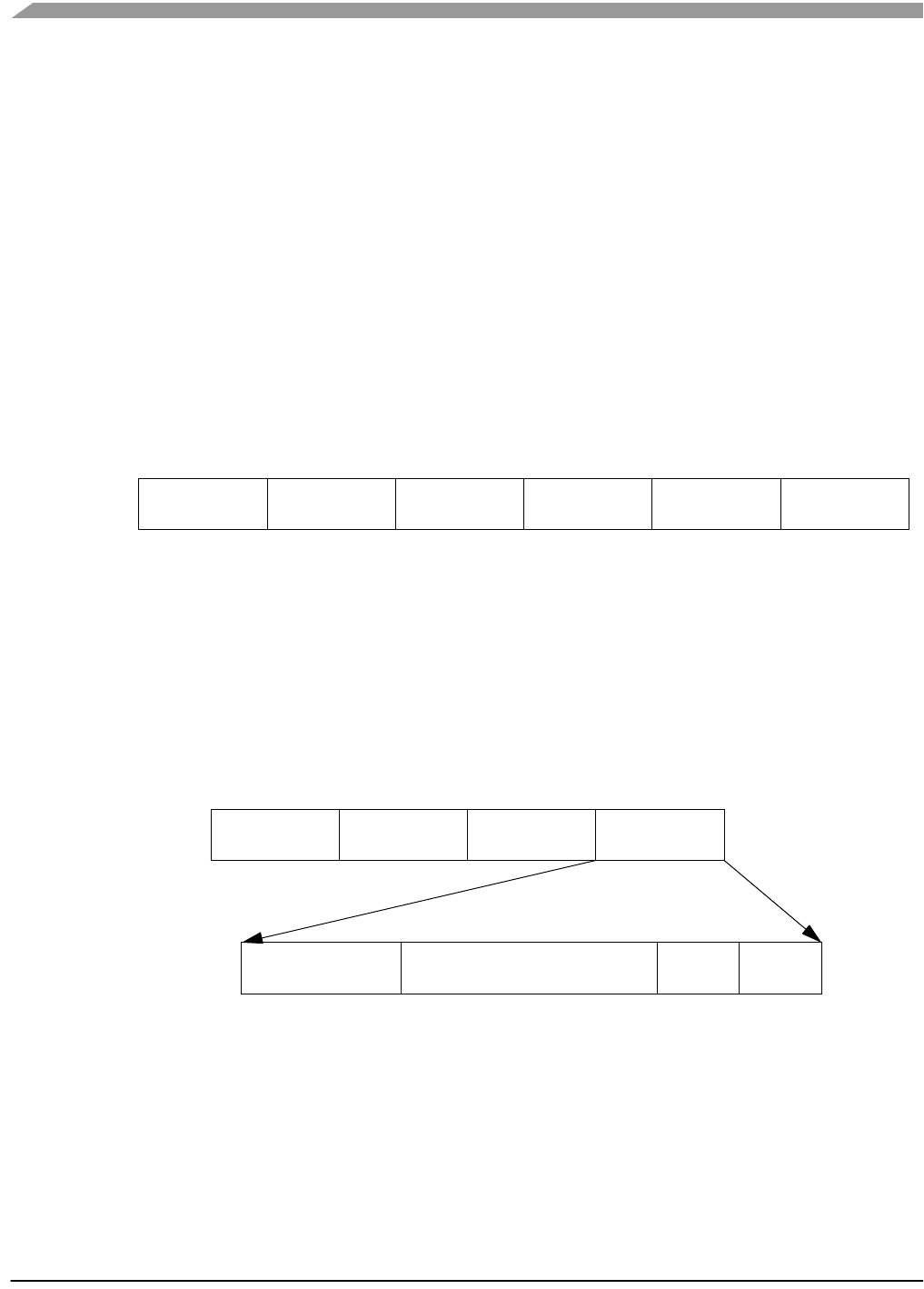
Figure 5-2ZSTAR_CONNECT Zdata format
5.3.2.3 ZSTAR_DATA
Once the connection is established, the Sensor Board starts to periodically transmit accelerometer, button
and g-range status data towards the USB stick.
The Zdata field contains 4 bytes; the actual X, Y and Z accelerometer values and a byte with status
information.
Figure 5-3ZSTAR_DATA Zdata format
Each transmission of a ZSTAR_DATA packet is acknowledged by a ZSTAR_ACK packet from the USB
stick, although the Sensor Board does not always open the reception window to receive this
acknowledgement, in order to save the battery charge.
Xvalue (0g) Xvalue (1g) Yvalue (0g) Yvalue (1g) Zvalue (0g) Zvalue (1g)
0 1 2 3 4 5
Zdata bytes:
Xvalue Yvalue Zvalue Status
0 1 2 3
msb lsb
Button1
Button2
unused
g-range
015-27 6bits:
Zdata bytes:

ZSTAR RF protocol
Wireless Sensing Triple Axis Reference design, Rev. 0.9
Freescale Semiconductor 41
5.3.2.4 ZSTAR_ACK
This command is sent as the data acknowledgement so the Sensor Board board knows that the
connection is still alive. If the receive window is opened by the Sensor Board and the ZSTAR_ACK has
not been received, the operation (periodic transmission of a ZSTAR_DATA packet) continues but the
Sensor Board will try to receive an acknowledgement more frequently. If the acknowledgement is not
received several times, the connection is dropped and the Sensor Board will try to re-establish the
connection again. The USB stick will recognize this situation once several ZSTAR_DATA packets have
not been received.
5.3.2.5 ZSTAR_CALIB
This command carries the calibration data provided by the USB stick for the Sensor Board and is sent
instead of a ZSTAR_ACK packet. The calibration data is intended to be stored in Flash memory of the
Sensor Board. Since the Sensor Board does not receive after every ZSTAR_DATA packet, the USB stick
keeps sending a ZSTAR_CALIB until the Sensor Board confirms reception using a new
ZSTAR_CONNECT packet.
5.3.2.6 ZSTAR_STATUS
This command carries the g-range data provided by the USB stick for the Sensor Board and is sent
instead of a ZSTAR_ACK packet. The g-range data is intended to switch the g-range of accelerometer
sensor. Since the Sensor Board does not receive after every ZSTAR_DATA packet, the USB stick keeps
sending a ZSTAR_STATUS until the Sensor Board confirms reception using a new ZSTAR_CONNECT
packet.

Software Design
Wireless Sensing Triple Axis Reference design, Rev. 0.9
42 Freescale Semiconductor
5.4 STAR protocol and ZSTAR extensions (over USB)
The ZSTAR demo uses a subset of the original STAR demo protocol commands. This way, most of the
software originally developed for the RD3112 (STAR) is also usable with the ZSTAR.
The STAR demo communicates over the RS232 serial line with a simple text-based protocol. The same
protocol is used in ZSTAR for communication between the USB stick and a PC (over a virtual serial port).
The PC application sees the same interface (serial port) and the same protocol as if a STAR demo was
connected.
5.4.1 Communication handshake ‘R’ (0x52)
Initially, a handshake (commands needed to test/establish the connection between the PC and the
ZSTAR demo) is conducted. This is accomplished by the PC sending an ‘R’ command, the ZSTAR demo
responding with ‘N’. In this way, the PC application sees that the demo is ready for communication.
Communication is reset, and any debug or system modes are disabled.
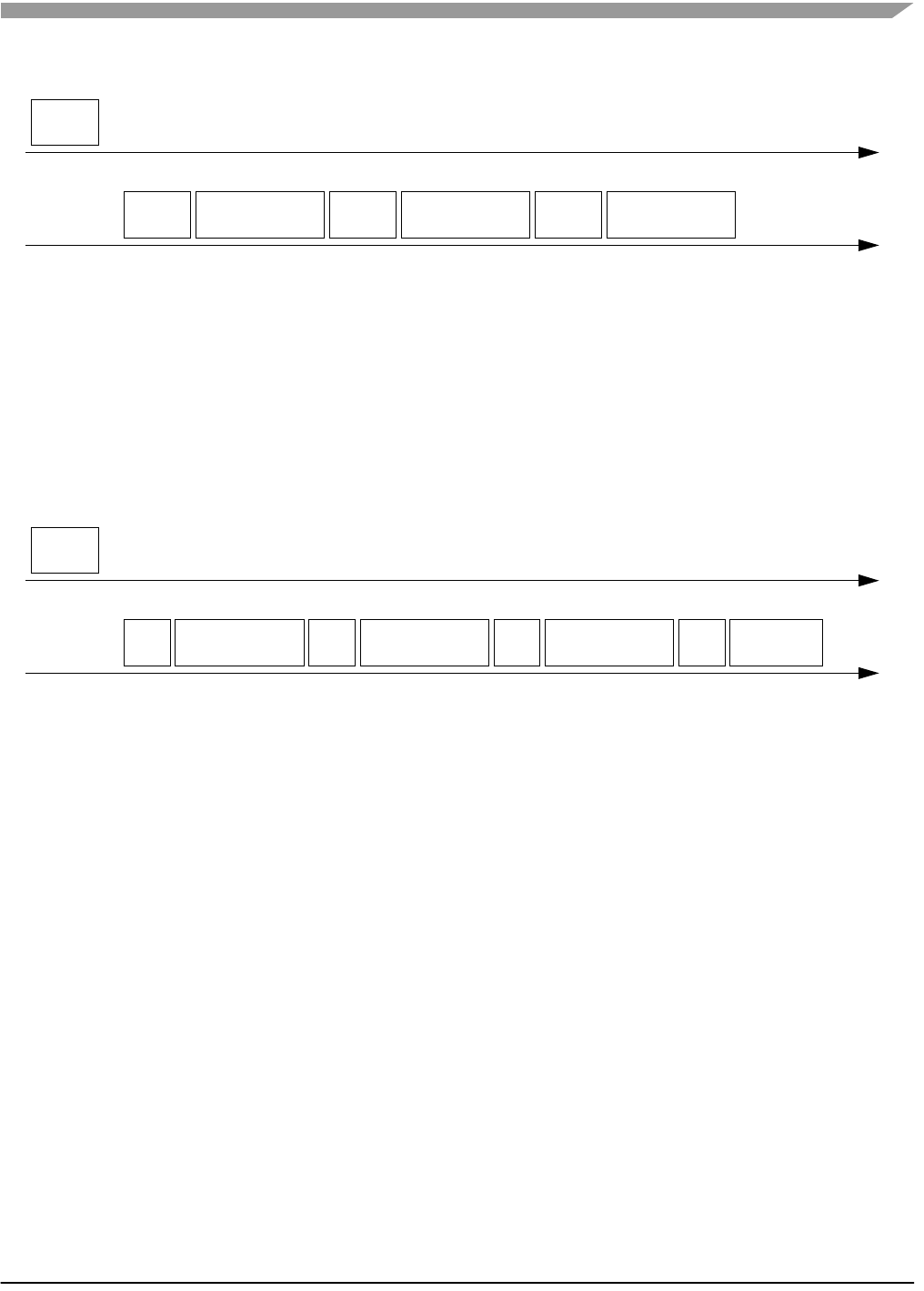
Figure 5-4Communication handshake ‘R’ (0x52)
5.4.1.1 Extended Communication handshake ‘r’ (0x72)
To determine whether a ZSTAR or STAR demo is connected, Only the ZSTAR demo implements an
Extended Handshake Communiation command. Once the PC sends the ‘r’ command, the ZSTAR demo
responds with a ‘Z’.
Figure 5-5Extended Communication handshake ‘r’ (0x72)
5.4.2 Accelerometer data transfer ‘V’ (0x56)
The PC sends the Values ‘V’ command, the demo responds with 6 bytes in the following sequence:
'x', X-value, 'y', Y-value, 'z', Z-value, simply an ‘x’ character followed by the actual X-axis accelerometer
binary value, then a ‘y’ followed by the actual Y-axis accelerometer binary value and a ‘z’ followed by the
actual Z-axis accelerometer binary value. Since the ZSTAR demo caches the last (over the air)
transmitted values, these values are immediately provided to the PC.
PC to demo
demo to PC
‘R’
‘N’
PC to demo
demo to PC
‘r’
‘Z’
STAR protocol and ZSTAR extensions (over USB)
Wireless Sensing Triple Axis Reference design, Rev. 0.9
Freescale Semiconductor 43
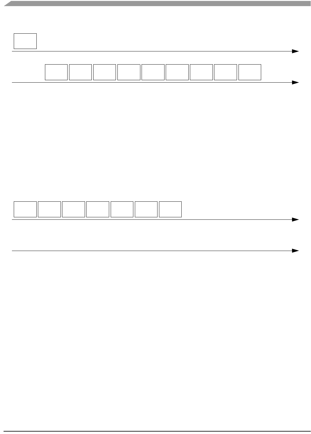
Figure 5-6Accelerometer data transfer ‘V’ (0x56)
5.4.2.1 Extended Accelerometer data transfer ‘v’ (0x76)
The ZSTAR demo has also two buttons designed on the Sensor Board. To acquire the actual state of
these buttons, the original ‘V’ command has been extended to a ‘v’ command, that provides the same
information, followed by a ‘b’ character and a binary byte containing the actual state. The least two
significant bits are used, the others are reserved. If a button is pressed, the actual bit is set to ‘1’, and if
depressed, the bit is ‘0’.
Figure 5-7Extended Accelerometer data transfer ‘v’ (0x76)
5.4.3 Calibration data ‘K’ (0x4B)
The calibration data is the accelerometer values for specific g (acceleration) levels. The values for 0g and
1g (Earth gravity) are provided for each axis. The values are stored in the Flash memory of the Sensor
Board and are transferred to the USB stick once the air connection is established (as described in chapter
5.3.2.2 ZSTAR_CONNECT). These values are stored in the USB stick for retrieval by the PC using the
‘K’ command.
The PC sends the Calibration data ‘K’ command, the demo responds with 9 bytes in the following
sequence:
'X', Xval0, Xval1, 'Y', Yval0, Yval1, Z', Zval0, Zval1, simply an ‘X’ character followed by the 0g and 1g
X-axis calibration accelerometer binary values, and the same for Y- and Z-axis.
PC to demo
demo to PC
X-axis value
‘x’ Y-axis value
‘y’ Z-axis value
‘z’
‘V’
PC to demo
demo to PC
X-axis value
‘x’
‘v’
Y-axis value
‘y’ Z-axis value
‘z’ buttons
‘b’
Software Design
Wireless Sensing Triple Axis Reference design, Rev. 0.9
44 Freescale Semiconductor
Figure 5-8Calibration data ‘K’ (0x4B)
5.4.4 Calibration process ‘k’ (0x6B)
The calibration process is initiated by a ‘k’ command from the PC, followed by 6 bytes of calibration data.
These are to be stored in the Flash memory of the Sensor Board being used. More in chapter 5.3.2.5
ZSTAR_CALIB.
The calibration data is just 6 bytes in the following sequence:
Xval0, Xval1, Yval0, Yval1, Zval0, Zval1 - 0g and 1g calibration accelerometer binary values for X-, Y-
and Z-axis. No response from the demo is provided. Verification of the calibration data stored can be done
using the Calibration data ‘K’ (0x4B) command.
Figure 5-9Calibration process ‘k’ (0x6B)
5.4.4.1 Remaining STAR demo commands
The remaining STAR commands, such as 'F', 'G', 'H', '0', '1', '2', '3' and 'E' are not implemented in the
ZSTAR demo.
5.4.5 Additional ZSTAR commands
5.4.5.1 g-select reading ‘G’ (0x47)
The ZSTAR demo allows dynamic selection of the g-range for the accelerometer sensor (see details in
chapter 3.4.2 g-select connections), thus additional commands are implemented to read and change the
g-range.
When the PC issues a ‘G’ command, the ZSTAR demo responds with the g-range actually selected. A ‘0’,
‘1’, ‘2’ or ‘3’ character is returned where ‘0’ is for the 1.5g range, ‘1’ for 2.0g , ‘2’ for 4.0g and ‘3’ for the
6.0g range. If a different sensor (e.g. MMA7261Q) is implemented on the Sensor Board, the g-ranges are
2.5g, 3.3g, 6.7g and 10g respectively.
PC to demo
demo to PC
x(0g)
‘X’ ‘Y’ ‘Z’
‘K’
x(1g) y(0g) y(1g) z(0g) z(1g)
PC to demo
demo to PC
x(0g)
‘k’ x(1g) y(0g) y(1g) z(0g) z(1g)
STAR protocol and ZSTAR extensions (over USB)
Wireless Sensing Triple Axis Reference design, Rev. 0.9
Freescale Semiconductor 45
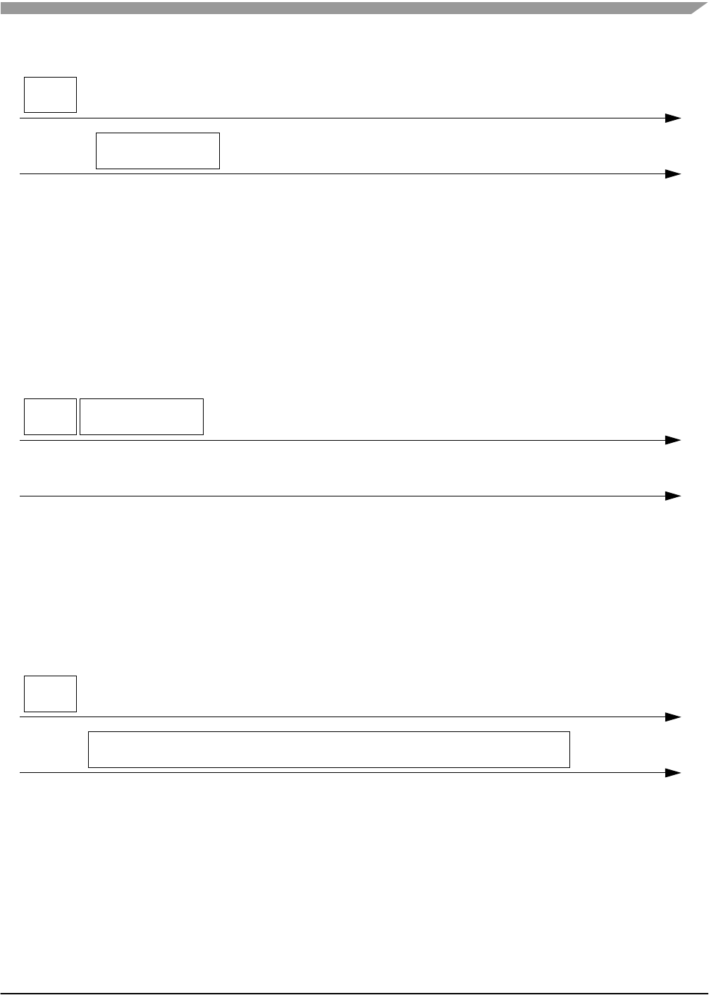
Figure 5-10g-select reading ‘G’ (0x47)
5.4.5.2 g-select setting ‘g’ (0x67)
To select the g-range of the sensor on the ZSTAR Sensor Board, a ‘g’ command is issued. It needs to be
followed by the required g-range (‘0’, ‘1’, ‘2’ or ‘3’). The USB stick board then communicates this selection
to the Sensor Board over the air (see more in 5.3.2.6 ZSTAR_STATUS).
No response from the demo is provided. To verify which g-range has been selected, the g-select reading
‘G’ (0x47) command can be used.
Figure 5-11g-select setting ‘g’ (0x67)
5.4.5.3 Info ‘I’ (0x49)
The Info command ‘I’ has only been added to determine which version, compile date, and author of the
USB stick software has been implemented. The demo returns a plain text information, and this command
is usually issued over terminal (e.g. HyperTerminal) software.
Figure 5-12Info ‘I’ (0x49)
5.4.5.4 Debug on ‘U’ (0x55) and Debug off ‘u’ (0x75)
Various debug information can be observed after issuing a ‘U’ command, usually in terminal (e.g.
HyperTerminal) software. Mainly, information on the air protocol is displayed in text, information on the
detected channel energy during the surveying for a free channel is shown, channel numbers, and, once
the connection is established, the network number. The received level of packets from the Sensor Board
PC to demo
demo to PC
‘G’
g-select value
PC to demo
demo to PC
‘g’ g-select value
PC to demo
demo to PC
‘I’
info text, version, date, etc.

Software Design
Wireless Sensing Triple Axis Reference design, Rev. 0.9
46 Freescale Semiconductor
and the reported USB stick packet level are shown, as well as command names, etc. This can be useful
in determining the communication range between the USB stick and the Sensor Board.
The debug information is no longer displayed after issuing a ‘u’ command or Communication handshake
‘R’ (0x52).
Figure 5-13Debug on ‘U’ (0x55) and Debug off ‘u’ (0x75)
5.4.6 Further debug and test commands
5.4.6.1 Forced channel number selection
In order to allow effective testing and debugging, few additional commands have been added. If, before
a connection between the USB stick and Sensor Board is established, any hexadecimal number
command (‘0’ through ‘9’ or ‘A’ through ‘F’) is sent, the connection will be established on this specific
channel number (0 to 15). Any new channel can be selected, sending the new channel number command.
The selection becomes effective during the new connection is being established.
The return to the automatic mode (where a random channel with the minimum energy is selected) can be
forced only by a complete software reset (ie. removing the USB stick from the USB slot).
5.4.6.2 Semiautomatic self-calibration
For the purpose of easier semiautomatic calibration of the ZSTAR demo, additional Calibration command
‘Q’ (0x51) has been added. This command is usually issued over terminal (e.g. HyperTerminal) software.
A user is required to place the Sensor Board into 3 specific positions, in which the Earth gravity will induce
a maximum acceleration in each of X, Y, and Z axes. Before issuing the first ‘Q’ command, the Sensor
Board must be placed flat, ie. with Z-axis aiming toward the Earth core. For the second issue of ‘Q’
calibration command, the board’s X-axis has to aim toward the Earth core. The board should ‘stay’ on its
right edge. Next, the Y-axis is calibrated, with the board ‘staying’ on its top edge. Finally, after issuing the
fourth ‘Q’ command, the calibration data are sent to the Sensor Board, actually using ZSTAR_CALIB
command. The text help is provided during the self-calibration process.
PC to demo
demo to PC
‘U’
various debug information
‘u’
no debug info
mainly on air protocol

Bootloader
Wireless Sensing Triple Axis Reference design, Rev. 0.9
Freescale Semiconductor 47
5.5 Bootloader
There’s bootloader software implemented in MCHC908JW32 microcontroller. The bootloader is based on
AN2295 Application note - Developer’s Serial Bootloader for M68HC08 and HCS08 MCUs and
AN2295SW accompanied software. The original AN2295 bootloader targets serial connections between
the PC and applications, and since the MCHC908JW32 implements a virtual serial port application, the
USB version of the AN2295 bootloader has been created to allow reprogramming of Flash memory in the
USB stick.
The USB virtual serial port software is fully described in AN3153 Application note - Using the Full-Speed
USB Module on the MCHC908JW32; the MCHC908JW32 bootloader implements the same virtual serial
port but under a different PID (the PC sees that serial port as a different application from ZSTAR).
The bootloader drivers installation guide can be found in chapter 6.1.2 AN2295 Bootloader Drivers
installation.
Software Design
Wireless Sensing Triple Axis Reference design, Rev. 0.9
48 Freescale Semiconductor
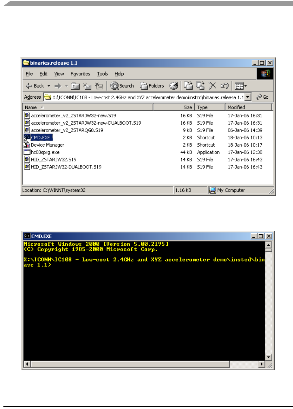
5.5.1 Bootloading procedure
1. Find on the installation CD the folder with binaries:
2. Start (double-click) the CMD.EXE shortcut, a command line window should appear:
Bootloader
Wireless Sensing Triple Axis Reference design, Rev. 0.9
Freescale Semiconductor 49
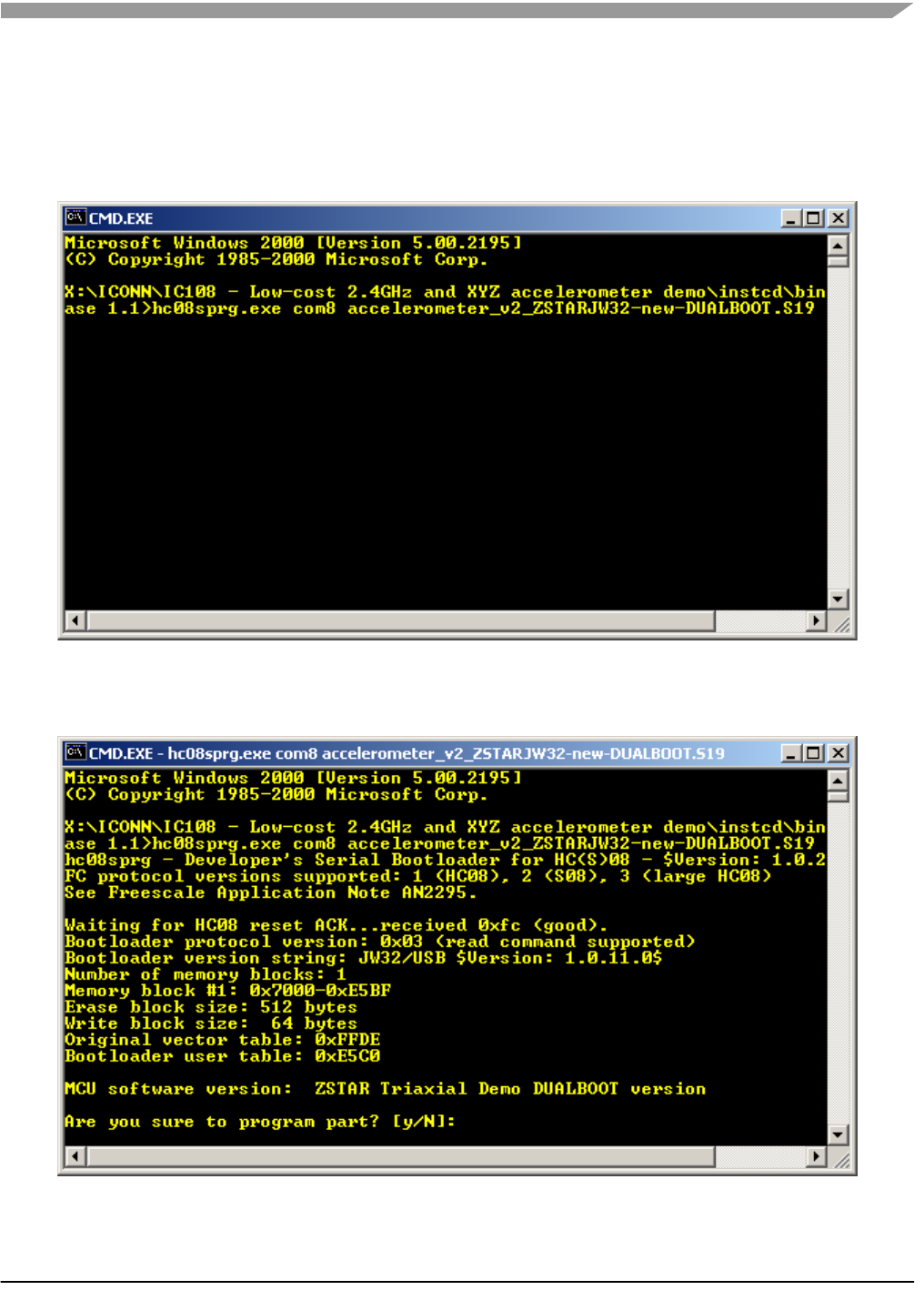
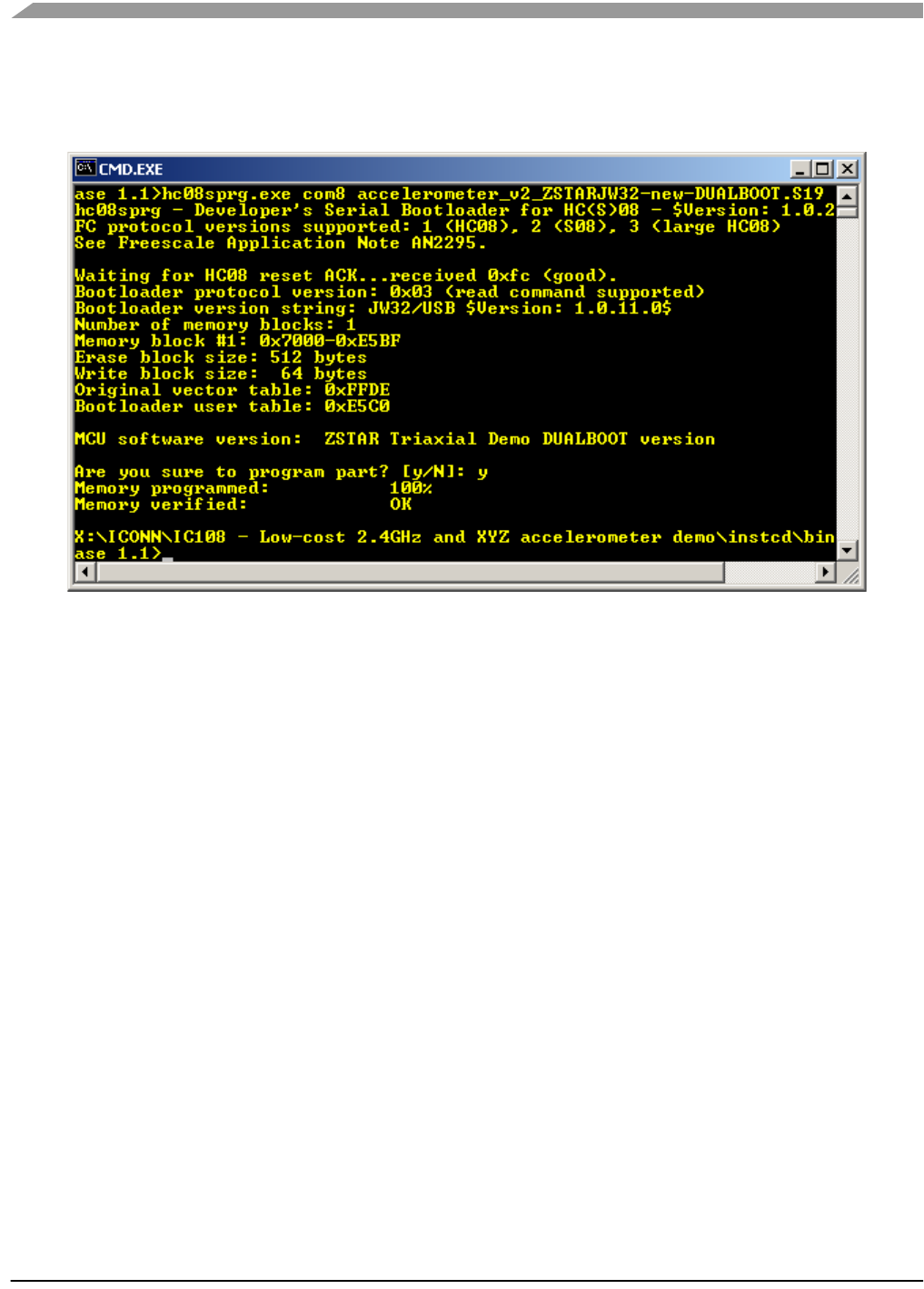
3. Now type: hc08sprg [bootloader com port number] [binary (S file) that you want to bootload], just
like this:
hc08sprg.exe com8 accelerometer_v2_ZSTARJW32-new-DUALBOOT.S19
4. Press ENTER and initial bootloader communication will start:
If this screen does not appear, remove the USB stick and start from the beginning.
Software Design
Wireless Sensing Triple Axis Reference design, Rev. 0.9
50 Freescale Semiconductor
5. Just confirm with Y, and the binary will be loaded onto the USB stick:
The bootloader disappears (in Device Manager) and the newly loaded software starts to execute.
Using this procedure the software in the USB stick can be changed anytime.
Bootloader
Wireless Sensing Triple Axis Reference design, Rev. 0.9
Freescale Semiconductor 51
5.5.2 Dualboot guidelines
NOTE: The USB stick already comes from factory with two dualboot-aware applications pre-programmed.
USB stick and AN2295 Bootloader software provide a way of having two different software (devices) in
one USB stick. In order to do this, two dualboot-aware versions of the software needs to be consecutively
bootloaded onto the USB stick:
Follow the sequence of instructions in the 5.5.1 Bootloading procedure for two dualboot versions of
software:
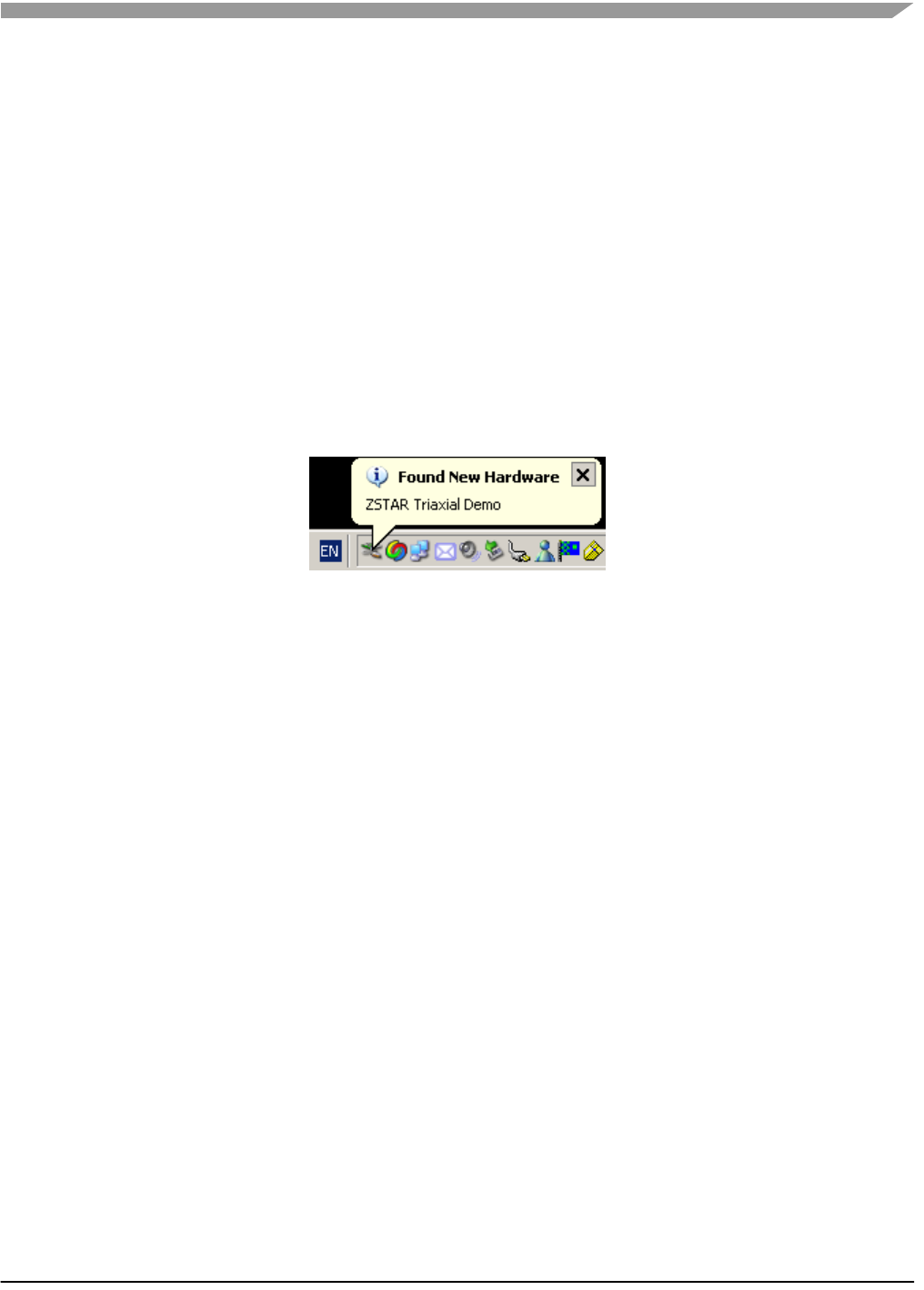
1. First bootload accelerometer_v2_ZSTARJW32-new-DUALBOOT.S19.
After bootloading, ZSTAR Triaxial Demo (COM1) should appear in Device Manager.
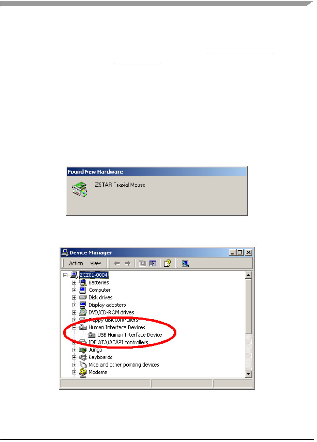
2. Next, remove the USB stick again, press the button, re-insert the stick and bootload
HID_ZSTARJW32-DUALBOOT.S19 software in.
After bootloading, a new device (ZSTAR Triaxial Mouse) should appear:
The ‘tilt’ mouse will install automatically and also appear in the Device Manager:

Software Design
Wireless Sensing Triple Axis Reference design, Rev. 0.9
52 Freescale Semiconductor
5.5.2.1 Dualboot applications switching
Having both dualboot-aware applications programmed in the USB stick, they can be switched just by
quickly pressing the button (having the USB stick inserted into the USB slot). The applications will appear
and disappear accordingly.
The ‘tilt’ mouse application in order to work must have sensor board calibrated correctly (e.g. using
RD3152MMA7260Q_SW.exe or 5.4.6.2 Semiautomatic self-calibration procedure).
Wireless Sensing Triple Axis Reference design, Rev. 0.9
Freescale Semiconductor 53
Chapter 6
Application Setup
6.1 ZSTAR Installation Procedure
6.1.1 USB stick installation
First of the all, we have to install the USB stick to your PC. Please follow the next steps.
1. Plug the USB stick into a USB slot.The ‘Found New Hardware’ announcement should appear:
Application Setup
Wireless Sensing Triple Axis Reference design, Rev. 0.9
54 Freescale Semiconductor
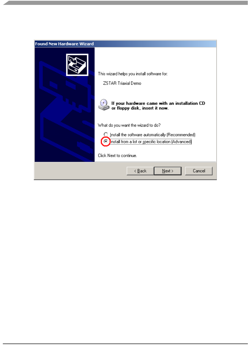
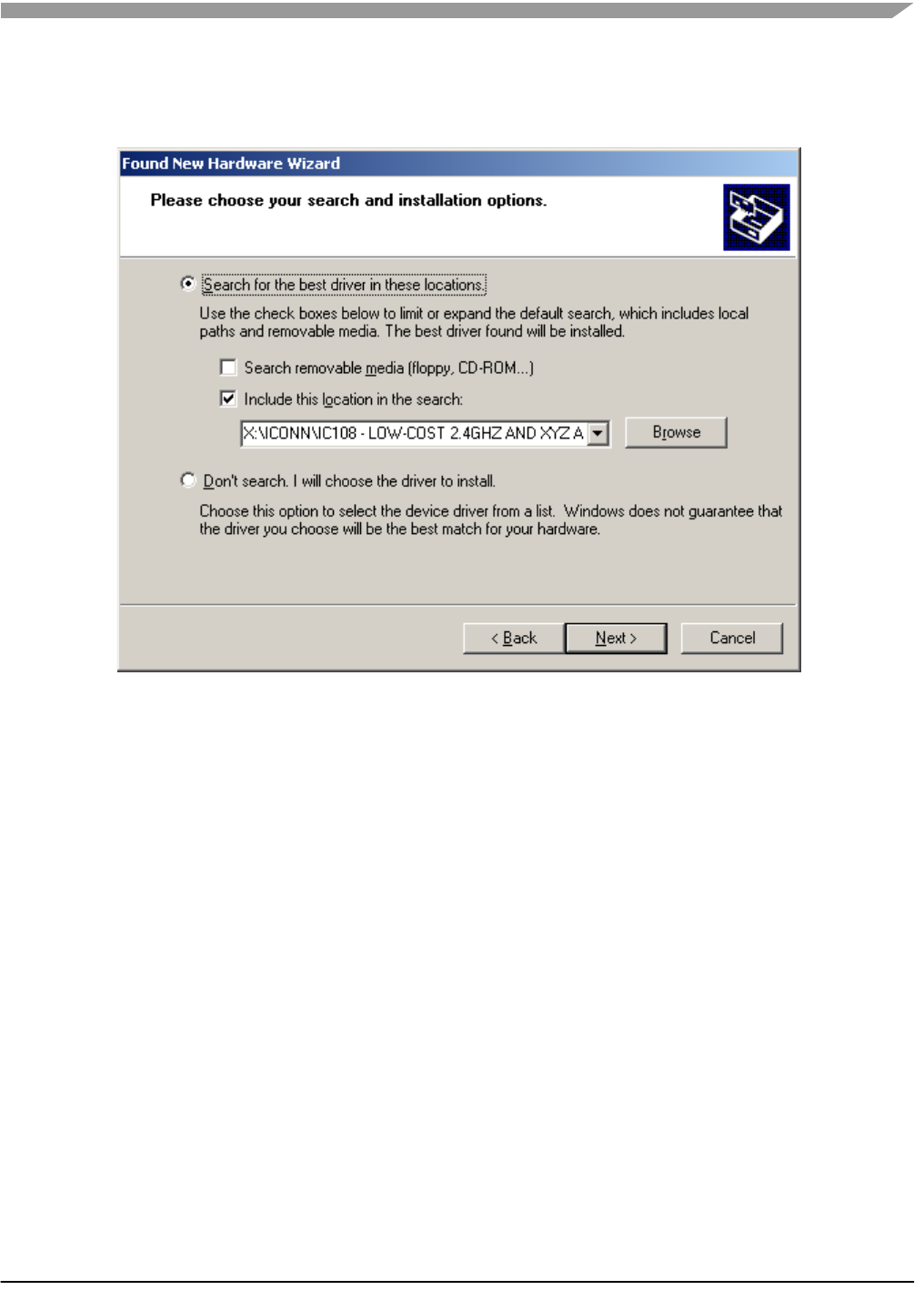
2. Then the installation wizard starts for new hardware. Choose “Install from a list or special location“
ZSTAR Installation Procedure
Wireless Sensing Triple Axis Reference design, Rev. 0.9
Freescale Semiconductor 55
3. Point to the Installation CD as the driver path:
Application Setup
Wireless Sensing Triple Axis Reference design, Rev. 0.9
56 Freescale Semiconductor
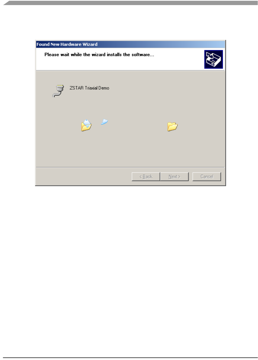
4. Installation should continue:
ZSTAR Installation Procedure
Wireless Sensing Triple Axis Reference design, Rev. 0.9
Freescale Semiconductor 57
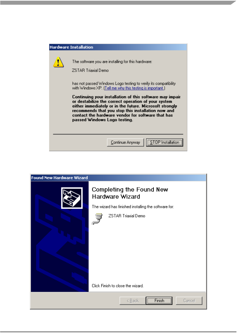
5. If you are using Windows XP SP2, you will be asked to stop or continue installation because the
drivers are not certified by Microsoft. Select the “Continue Anyway” button
6. Installation should succesfully finish.
Application Setup
Wireless Sensing Triple Axis Reference design, Rev. 0.9
58 Freescale Semiconductor
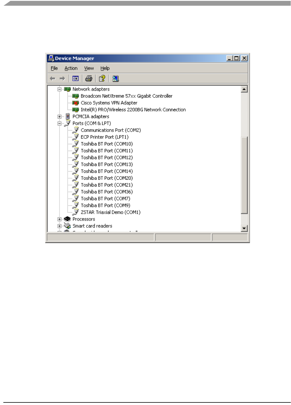
7. Check whether a new serial port (ZSTAR Triaxial Demo) has appeared in your Device Manager
(My Computer, right click, Manage, Device Manager):
8. If required, the ZSTAR Triaxial Demo COM port maybe renumbered using the standard procedure
in Windows operating system:
Right click for Properties,Port Settings tab, Advanced button and change the COM port number
accordingly.
ZSTAR Installation Procedure
Wireless Sensing Triple Axis Reference design, Rev. 0.9
Freescale Semiconductor 59
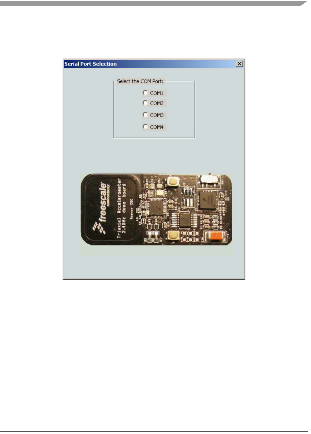
9. Launch the RD3152 software “RD3152MMA7260QSW.exe" and select the COM port number
which you may have assigned in Device Manager.
Figure 6-1
If no error message appears, the COM port is opened correctly and software communicates with the USB
stick.
10. Now lets go and check data from the ZSTAR Sensor Board.
Raw data, 2D/3D screen, or Scope work should be used for this purpose. While moving (turning, shaking)
with a ZSTAR Sensor Board, data from the separate axis should change accordingly.
The RD3152MMA7260QSW calibration screen can be used for sensor calibration (calibration data is
stored in the Sensor Board).
Application Setup
Wireless Sensing Triple Axis Reference design, Rev. 0.9
60 Freescale Semiconductor
6.1.2 AN2295 Bootloader Drivers installation
This procedure assumes that ZSTAR Demo drivers are already installed. The drivers are alse common
for the bootloader (= are already present in Windows folders). If not, the procedure will be identical to the
ZSTAR drivers installation.
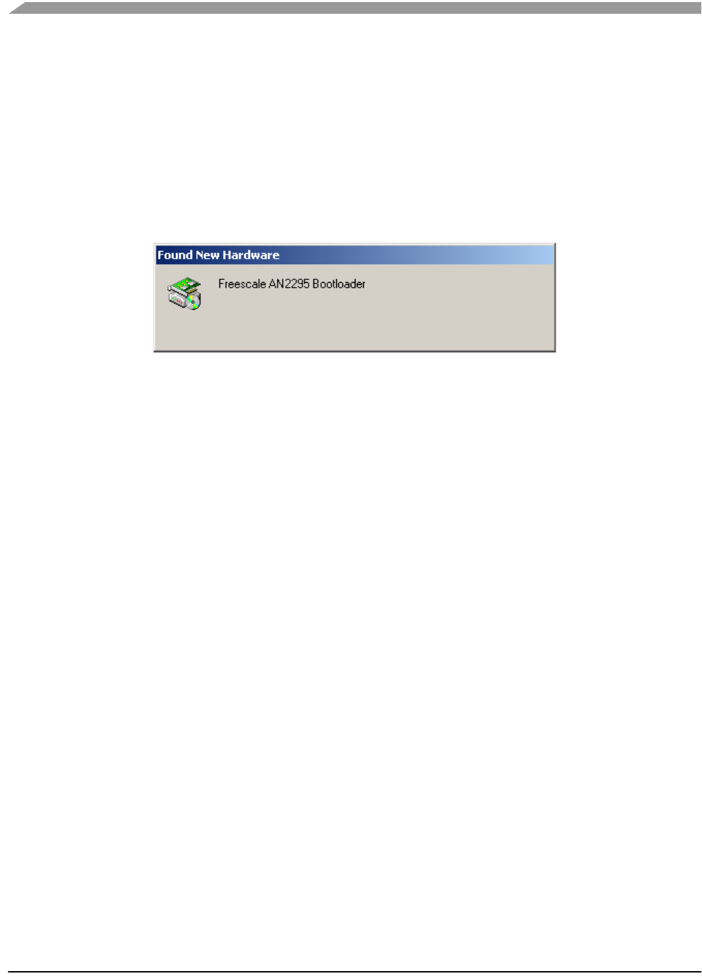
1. Press the Button on the USB stick and insert it into a USB connector (keeping the button pressed
when inserted).
The following window appears:
ZSTAR Installation Procedure
Wireless Sensing Triple Axis Reference design, Rev. 0.9
Freescale Semiconductor 61
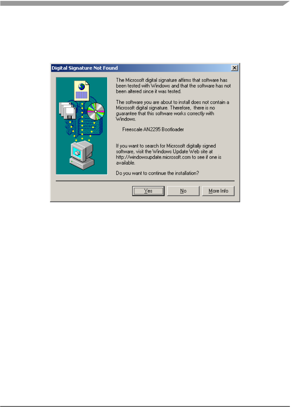
2. The PC searches for an appropriate driver (as the ZSTAR Demo, in some instances a folder with
drivers (zstar.inf and usbser.sys) needs to be selected), then the following window should
appear:
3. Just click Yes, and the bootloader port will be installed (as seen in the Device manager):
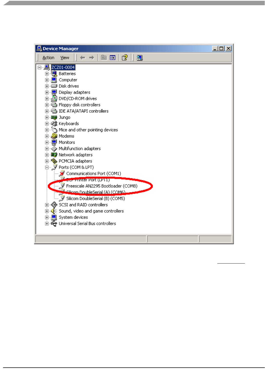
4. Right click My computer on the Desktop > Properties,Hardware tab, Device Manager button.
Application Setup
Wireless Sensing Triple Axis Reference design, Rev. 0.9
62 Freescale Semiconductor
5. A similar setup should be observed:
6. Note down the COM port number (here, COM8); this is the port number of the Bootloader
Once the software in the USB stick needs to be updated, the Bootloader can be invoked anytime, just by
pressing the button while inserting the USB stick into the USB slot.

Wireless Sensing Triple Axis Reference design, Rev. 0.9
Freescale Semiconductor 63
Appendix A
References
The following documents can be found on the Freescale web site: http://www.freescale.com.
1. AN2295 Application note - Developer’s Serial Bootloader for M68HC08 and HCS08 MCUs
2. AN3153 Application note - Using the Full-Speed USB Module on the MCHC908JW32
3. MC9S08QG8 Datasheet
4. MCHC908JW32 Datasheet
5. MMA7260Q Datasheet
6. MC13191 Datasheet

Wireless Sensing Triple Axis Reference design, Rev. 0.9
64 Freescale Semiconductor

How to Reach Us:
Home Page:
www.freescale.com
E-mail:
support@freescale.com
USA/Europe or Locations Not Listed:
Freescale Semiconductor
Technical Information Center, CH370
1300 N. Alma School Road
Chandler, Arizona 85224
+1-800-521-6274 or +1-480-768-2130
support@freescale.com
Europe, Middle East, and Africa:
Freescale Halbleiter Deutschland GmbH
Technical Information Center
Schatzbogen 7
81829 Muenchen, Germany
+44 1296 380 456 (English)
+46 8 52200080 (English)
+49 89 92103 559 (German)
+33 1 69 35 48 48 (French)
support@freescale.com
Japan:
Freescale Semiconductor Japan Ltd.
Headquarters
ARCO Tower 15F
1-8-1, Shimo-Meguro, Meguro-ku,
Tokyo 153-0064
Japan
0120 191014 or +81 3 5437 9125
support.japan@freescale.com
Asia/Pacific:
Freescale Semiconductor Hong Kong Ltd.
Technical Information Center
2 Dai King Street
Tai Po Industrial Estate
Tai Po, N.T., Hong Kong
+800 2666 8080
support.asia@freescale.com
For Literature Requests Only:
Freescale Semiconductor Literature Distribution Center
P.O. Box 5405
Denver, Colorado 80217
1-800-441-2447 or 303-675-2140
Fax: 303-675-2150
LDCForFreescaleSemiconductor@hibbertgroup.com
RoHS-compliant and/or Pb-free versions of Freescale products have the functionality
and electrical characteristics of their non-RoHS-compliant and/or non-Pb-free
counterparts. For further information, see http://www.freescale.com or contact your
Freescale sales representative.
For information on Freescale’s Environmental Products program, go to
http://www.freescale.com/epp.
Information in this document is provided solely to enable system and software
implementers to use Freescale Semiconductor products. There are no express or
implied copyright licenses granted hereunder to design or fabricate any integrated
circuits or integrated circuits based on the information in this document.
Freescale Semiconductor reserves the right to make changes without further notice to
any products herein. Freescale Semiconductor makes no warranty, representation or
guarantee regarding the suitability of its products for any particular purpose, nor does
Freescale Semiconductor assume any liability arising out of the application or use of any
product or circuit, and specifically disclaims any and all liability, including without
limitation consequential or incidental damages. “Typical” parameters that may be
provided in Freescale Semiconductor data sheets and/or specifications can and do vary
in different applications and actual performance may vary over time. All operating
parameters, including “Typicals”, must be validated for each customer application by
customer’s technical experts. Freescale Semiconductor does not convey any license
under its patent rights nor the rights of others. Freescale Semiconductor products are
not designed, intended, or authorized for use as components in systems intended for
surgical implant into the body, or other applications intended to support or sustain life,
or for any other application in which the failure of the Freescale Semiconductor product
could create a situation where personal injury or death may occur. Should Buyer
purchase or use Freescale Semiconductor products for any such unintended or
unauthorized application, Buyer shall indemnify and hold Freescale Semiconductor and
its officers, employees, subsidiaries, affiliates, and distributors harmless against all
claims, costs, damages, and expenses, and reasonable attorney fees arising out of,
directly or indirectly, any claim of personal injury or death associated with such
unintended or unauthorized use, even if such claim alleges that Freescale
Semiconductor was negligent regarding the design or manufacture of the part.
Freescale™ and the Freescale logo are trademarks of Freescale Semiconductor, Inc.
All other product or service names are the property of their respective owners.
© Freescale Semiconductor, Inc. 2006. All rights reserved.
ZSTARRM
Rev. 0.9, 3/2006