Friedrich Luetze 77920X0401 Ethernet Switch User Manual BA LCOS Unmanaged Switch V00 EN
Friedrich Luetze GmbH Ethernet Switch BA LCOS Unmanaged Switch V00 EN
Users Manual
Operating Instructions
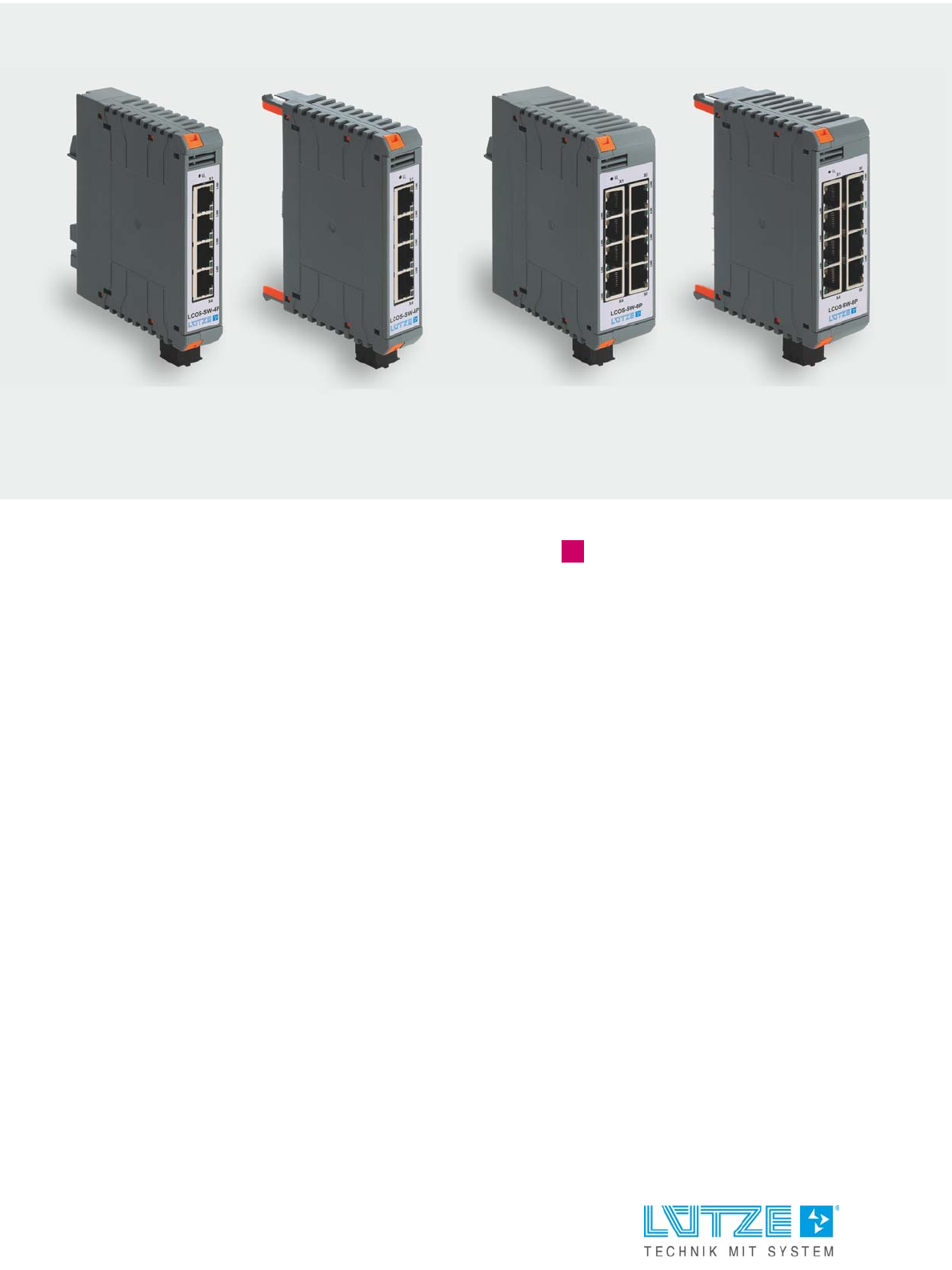
LCOS Unmanaged Switch
4 ports / 8 ports
779200.0401, LCOS-SW-4P
779201.0401, LCOS-SW-4P
779200.0801, LCOS-SW-8P
779201.0801, LCOS-SW-8P
Version 00
23.08.2018

Friedrich Lütze GmbH
Postfach 1224 (PLZ 71366)
Bruckwiesenstrasse 17-19
D-71384 Weinstadt
GERMANY / DEUTSCHLAND
Tel.: +49 (0) 7151 6053-0
Fax: +49 (0) 7151 6053-277(-288)
info@luetze.de
www.luetze.com
The company Friedrich Lütze GmbH reserves the right to make changes to its products in the interest
of technical development. These changes are not necessarily documented in each individual case.
This manual and the information contained herein have been compiled with due care. However, the
company Friedrich Lütze GmbH accepts no liability for printing or other errors or resulting damage.
The brands and product names mentioned in this book are trademarks or registered trademarks of the
respective titleholders.
© Copyright 2018 by Friedrich Lütze GmbH. All rights reserved.

LCOS Unmanaged Switch ▪ Contents
1
TRANSPORTATION
1 Introduction....................................................................................................... 4
1.1 About these instructions .............................................................................................................. 5
2 General Information.......................................................................................... 6
2.1 Safety instructions and technical information .............................................................................. 6
2.2 Copyright ..................................................................................................................................... 6
2.3 Disclaim of Liability ...................................................................................................................... 6
2.4 Standards and norms .................................................................................................................. 7
2.5 Scope of validity of the manual.................................................................................................... 8
2.6 Approvals..................................................................................................................................... 9
2.7 Applicable documents................................................................................................................ 11
3 Safety............................................................................................................... 12
3.1 Contents of the operating instructions ....................................................................................... 12
3.2 Applicable documents................................................................................................................ 12
3.3 Appropriate Use......................................................................................................................... 12
3.4 Product life................................................................................................................................. 13
3.5 Addressees................................................................................................................................ 14
3.6 Responsibility of the operator .................................................................................................... 15
3.7 Changes and modifications to the devices ................................................................................ 15
3.8 Safety device ............................................................................................................................. 15
3.9 Special safety notes................................................................................................................... 15
3.10 Further safety notes .................................................................................................................. 17
4 Product Overview ........................................................................................... 18
4.1 Construction types ..................................................................................................................... 18
4.2 Overview of product features..................................................................................................... 19
4.3 Function carrier (with power module) ........................................................................................ 21
5 Transport and storage.................................................................................... 22
6 Scope of delivery............................................................................................ 23
6.1 The LCOS Unmanaged Switch consists of:............................................................................... 23
6.2 Accessories ............................................................................................................................. 23
6.3 Checking the delivery ................................................................................................................ 24
7 Product Assembly .......................................................................................... 25
7.1 LCOS Unmanaged Ethernet-Switches ...................................................................................... 25
7.2 LED status displays ................................................................................................................... 26
8 Technical Data ................................................................................................ 27
8.1 Identification............................................................................................................................... 27
8.2 Description................................................................................................................................. 27
8.3 Communication.......................................................................................................................... 27
8.4 Safety......................................................................................................................................... 27
8.5 General ...................................................................................................................................... 27
9 Mounting / Dismounting................................................................................. 29
9.1 Installation position .................................................................................................................... 29
9.2 Mounting .................................................................................................................................... 30
9.3 Wiring......................................................................................................................................... 36
9.4 Pin assignment .......................................................................................................................... 37
9.5 Further information on the LCOS system (basics)..................................................................... 38
9.6 Coding of LCOS modules .......................................................................................................... 39
9.7 Installing Data and Power Bridges............................................................................................. 40
10 Commissioning - Hardware .......................................................................... 41
10.1 Safety notes Power supply .................................................................................................. 41
10.2 Safety notes Housing................................................................................................................. 42

LCOS Unmanaged Switch ▪ Contents
2
TRANSPORTATION
11 Operation......................................................................................................... 43
11.1 Functional description................................................................................................................ 43
11.2 Frame-Switching functionalities ................................................................................................. 43
11.3 Specific functions of the Ethernet interface ............................................................................... 44
11.4 Other functions and features ..................................................................................................... 44
11.5 Display elements ....................................................................................................................... 44
11.6 Interfaces ................................................................................................................................... 45
12 Maintenance - Hardware ................................................................................ 46
13 Final Shutdown and Disposal........................................................................ 47
14 Service............................................................................................................. 48
15 Appendix ......................................................................................................... 49
15.1 Overview of other applicable documents................................................................................... 49
15.2 Explanation of abbreviations used............................................................................................. 50
16 Revision history.............................................................................................. 52
LCOS Unmanaged Switch ▪ Introduction
4
TRANSPORTATION
1 Introduction
These operating instructions are part of the LCOS Unmanaged Switch.
Before using the device, please read these operating instructions to avoid
possible dangers and to ensure proper use.
Short description LCOS Unmanaged (Industrial Ethernet) Switches
The LCOS unmanaged switches are highly suitable for use in industrial ethernet
networks. In addition to durability, the units also offer more performance, such as
QoS (Quality of services) or operation in Profinet and Ethernet IP. Thanks to their
modular design, the units can be supplied with power in the LCOS system either
by means of the existing connectors or via the energy bus. They can also be used
in building automation systems due to the fact that they can run on AC voltage.
The application temperature range is -25 °C to +70°C.
Read and understand these instructions before installing, operating, or
maintaining the equipment.
Risk of injury and damage to property due to non-observance of the
operating instructions.
Always read these operating instructions before planning the system in order
to avoid or reduce risks and damage.
These operating instructions contain important information on safety,
commissioning, operation, maintenance and disposal of the device.
Always keep the document at hand. This applies until the device is disposed of.
Pass on the operating instructions if the device is sold, distributed or loaned.
You can also find these operating instructions at www.luetze.com.
In the search field, enter either the product name: LCOS Unmanaged Switch
or the product number: 77920*

LCOS Unmanaged Switch ▪ Introduction
5
TRANSPORTATION
1.1 About these instructions
These operating instructions provide information on the handling of the LCOS
Unmanaged Switch over its entire product life cycle, from delivery to disposal.
Other documents apply in addition to these operating instructions. (See also
chapter „2.7 Applicable documents“ on page 11) in this document. Please
also refer to the data sheets associated with the products.
If you have suggestions for improving this document, please contact the company
Friedrich Lütze GmbH.
LCOS Unmanaged Switch ▪ General Information
6
TRANSPORTATION
2 General Information
2.1 Safety instructions and technical information
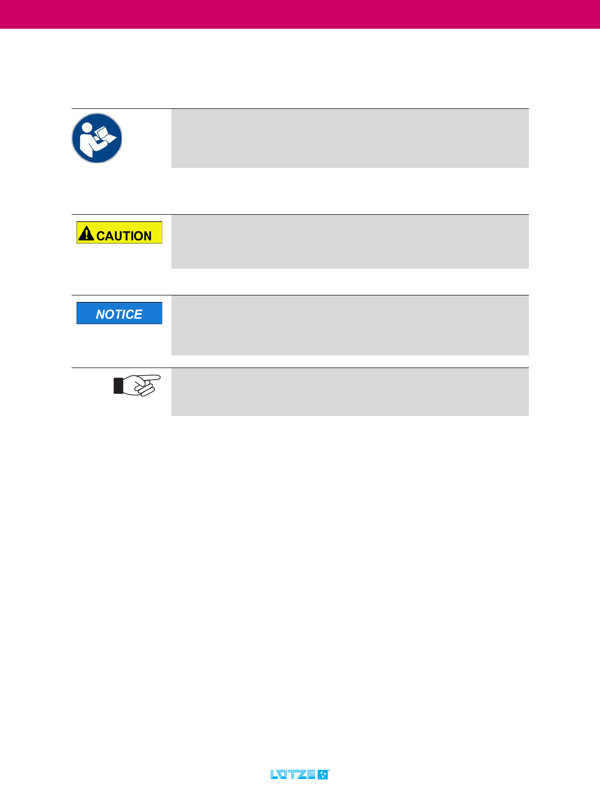
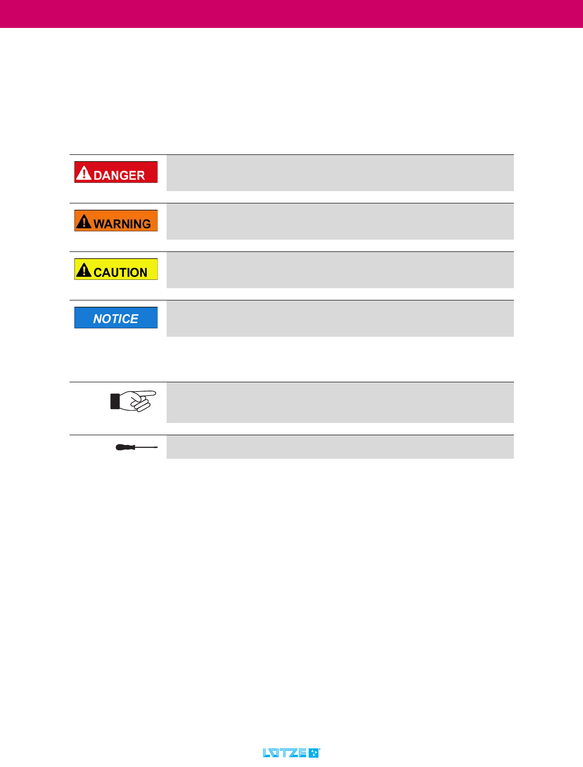
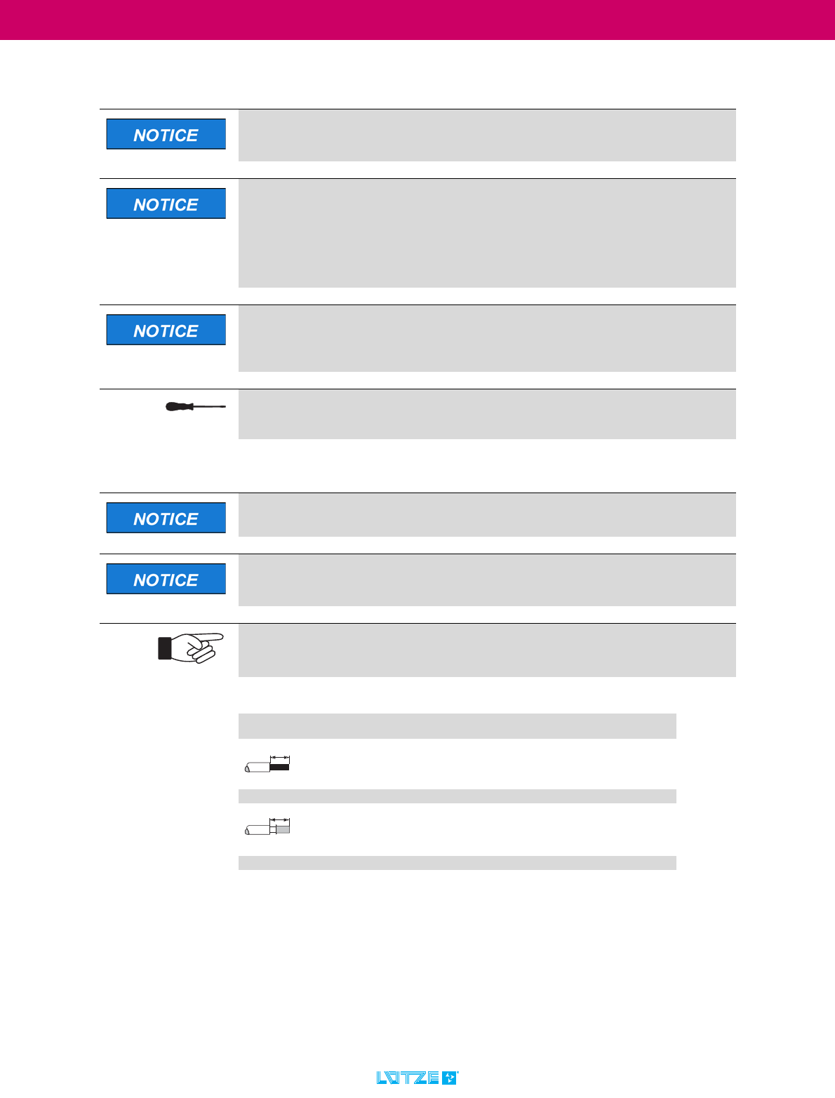
This document contains several safety messages. Each safety message contains
a defined signal word and a color. The color and the word are referring to an alert
level. There are 4 levels. The safety messages point out hazardous situations and
give information on how to avoid these.
Additionally following symbols can be found. These refer to important technical
information and instructions:
2.2 Copyright
This document is intended for the operator and his employees. It is forbidden to
give the content to a third party, to duplicate, exploit or impart it. The Friedrich
Lütze GmbH has to allow it explicit in writing.
General data, text, images and drawings are copyrighted and are liable to the
industrial property right. Contravention can be prosecuted. The named brands
and product names in this document are trademarks or registered trademarks by
titleholder.
2.3 Disclaim of Liability
The document was written under consideration of the applied standards,
regulations and the current state of technology.
The content is verified of accuracy. Discrepancies are not excluded. For those
discrepancies we disclaim liability. Applicable changes and additional information
will be in the next version of the document.
The Friedrich Lütze GmbH does not assume liability for any damages and
accidents of following reasons:
Indicates a hazardous situation, which if not avoided will result in death
or serious injury.
Indicates a hazardous situation, which if not avoided can result in death
or serious injury.
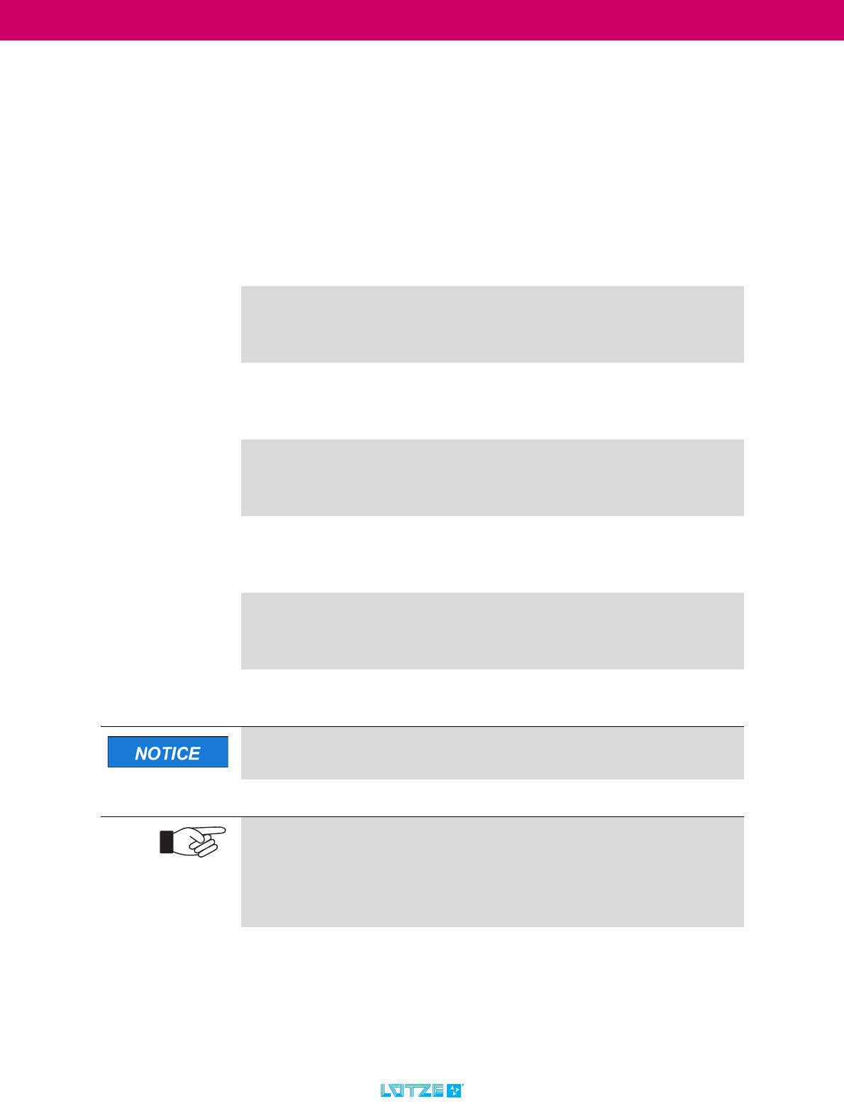
Indicates a hazardous situation, which if not avoided can result in minor
or moderate injury.
Indicates a situation which could damage the product or the environment.
This notice does not apply to personal injury.
Refers to important technical information.
This indicates to the user a specific action that must be performed to
operate the device safely.
Refers to the use of different tools.
LCOS Unmanaged Switch ▪ General Information
7
TRANSPORTATION
▪ Nonobservance of the document
▪ Untrained and unqualified personnel
▪ Non conventional use
▪ Non approved reconstructions and functional modifications of the product
▪ Using non original or non admitted parts or equipment
2.4 Standards and norms
LCOS Unmanaged switches are state of the technology and comply with the
applicable safety regulations and the corresponding harmonized European
standards (EN).
(As at: 21.08.2018)
EN 61131-2 Industrial-process control systems - Instruments with
analogue inputs and two- or multi-state outputs - Part 2:
Guidance for inspection and routine testing (IEC 65B/957/
CD:2014)
EN 61000-6-2 Electromagnetic compatibility (EMC) - Part 6-2: Generic
standards - Immunity standard for industrial environments
(IEC 77/488/CDV:2015); German version FprEN 61000-6-
2:2015
EN 61000-6-4 Electromagnetic compatibility (EMC) - Part 6-4: Generic
standards - Emission standard for industrial environments
(IEC 61000-6-4:2006 + A1:2010); German version
EN 61000-6-4:2007 + A1:2011
UL 61010-1 Safety requirements for electrical equipment for
measurement, control and laboratory use - Part 1: General
requirements (IEC 61010-1:2010 + Cor. :2011); German
version EN 61010-1:2010
UL 61010-2-201
(IEC 61010-2-201)
Safety Requirements for Electrical Equipment for
Measurement, Control, and Laboratory Use - Part 2-201:
Particular Requirements for Control Equipment (IEC 65/
582/CD:2014)
The current issue status of the standards as well as further information
on the product can be found in the respective data sheets.
The constantly updated data sheets can be found at www.luetze.com
Enter either the product name: LCOS Unmanaged Switch or this article
number: 77920* into the search field.
Here you will always find the latest documents (e.g. operating instructions) for
the products as well as further articles and technical information.
LCOS Unmanaged Switch ▪ General Information
8
TRANSPORTATION
2.5 Scope of validity of the manual
These operating instructions apply exclusively to devices with the following item
number(s):
1.) 779200.0401 / 779201.0401 - LCOS Unmanaged Switch 4 ports
2.) 779200.0801 / 779201.0801 - LCOS Unmanaged Switch 8 ports
The 9-digit article number of the device can be taken from the first number on the
Identification label.
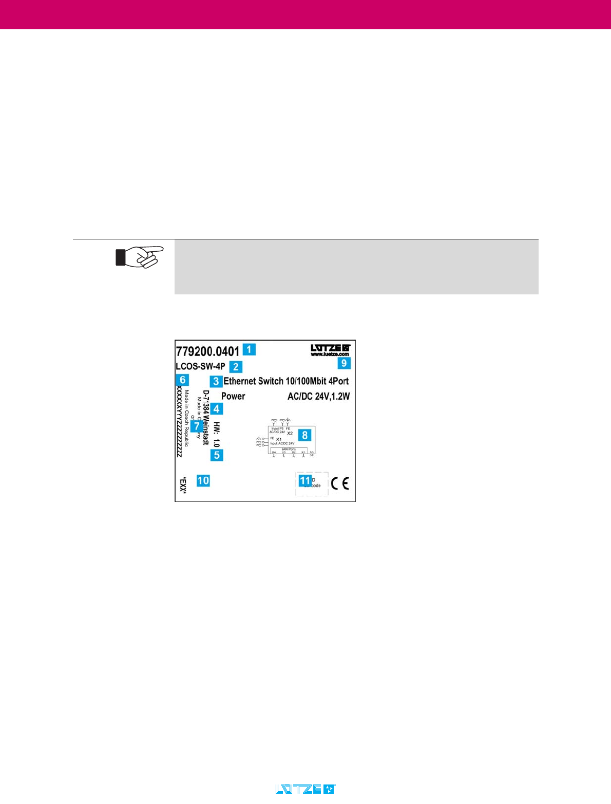
2.5.1 Identification label
The identification plate contains the required markings for the respective product
and provides important technical data.
The identification plate, which has the following structure, is located on the
device:
:
Abb. 1: Identification plate (example)
The identification label contains the following information:
1. Part number
2. Assembly designation / module description
3. Module Description
4. Version number / Firmware Version (SW) (Empty in the example)
5. Hardware Revision (HW)
6. Serial number (X) / place of manufacture (YYY) / batch identification (Z)
7. Company address / place of production (YYY: "LUT" for Weinstadt and "EQQ"
for Czech Republic)
8. Block diagram
9. Company name / web address
10.Approvals / declarations of conformity (e.g. CE marking, UL, etc.)
11.2D barcode with product information
Note the identification label.
▪ The identification label should always be visual
▪ If there is a fault, the part number and serial number are needed.
LCOS Unmanaged Switch ▪ General Information
9
TRANSPORTATION
2.6 Approvals
2.6.1 Notes on CE labelling
Observe the original information signs, inscriptions, identification plates
and stickers. Keep them in a readable condition.
The devices comply with the provisions of the following European Directive: 89/
336/EEC Council Directive on the approximation of the laws of the Member
States relating to electromagnetic compatibility (amended by Directives 91/263/
EEC, 92/31/EEC and 93/68/EEC).
The EU Declaration of Conformity is kept available for the competent authorities
in accordance with the above-mentioned EU directives:
Friedrich Lütze GmbH
Bruckwiesenstraße 17-19
71384 Weinstadt
GERMANY / DEUTSCHLAND
Telefon: +49 7151 60530
Telefax: +49 7151 6053277
E-Mail: info(at)luetze.de
The product can be used in industry.
- Immunity to interference: EN 61131-2:2007 Zone B
- Emitted interference:
EN 61131:2007 und CFR-47 Part 15, Subpart B, class B
Strict compliance with the assembly guidelines specified in this
description and operating instructions is a prerequisite for compliance
with the EMC limit values.

LCOS Unmanaged Switch ▪ General Information
10
TRANSPORTATION
2.6.2 FCC Warning Statements
1. This device complies with part 15 of the FCC Rules. Operation is subject to
the following two conditions:
(1) This device may not cause harmful interference, and (2) this device must
accept any interference received, including interference that may cause un-
desired operation. Any Changes or modifications not expressly approved by
the party responsible for compliance could void the user's authority to ope-
rate the equipment.
2. Any Changes or modifications not expressly approved by the party respon-
sible for compliance could void the user's authority to operate the equip-
ment.
This equipment has been tested and found to comply with the limits for a
Class B digital device, pursuant to part 15 of the FCC Rules. These limits
are designed to provide reasonable protection against harmful
interference in a residential installation. This equipment generates, uses
and can radiate radio frequency energy and, if not installed and used in
accordance with the instructions, may cause harmful interference to
radio communications. However, there is no guarantee that interference
will not occur in a particular installation. If this equipment does cause
harmful interference to radio or television reception, which can be
determined by turning the equipment off and on, the user is encouraged
to try to correct the interference by one or more of the following
measures:
▪ -Reorient or relocate the receiving antenna.
▪ -Increase the separation between the equipment and receiver.
▪ -Connect the equipment into an outlet on a circuit different from that
to which the receiver is connected.
▪ -Consult the dealer or an experienced radio/TV technician for help.
LCOS Unmanaged Switch ▪ General Information
11
TRANSPORTATION
2.7 Applicable documents
2.7.1 Observe other applicable documents
When operating the LCOS Unmanaged Switch, please also observe all operating
instructions enclosed with other components of your system.
For reasons of clarity, we would like to point out that these operating instructions
cannot describe all conceivable problems in connection with the use of this
device.
Should you require further information or encounter special problems that are not
dealt with in sufficient detail in the operating instructions, you can request the
necessary information about service from Lütze. (See chapter „14 Service“ on
page 48)
Further documents are valid in conjunction with these operating
instructions. We accept no liability for damage caused by non-
observance of these instructions.
Always keep these operating instructions and the other applicable
documents (e.g. data sheets, package inserts, declarations of conformity,
etc.) at hand so that they are available when required.
This applies until the device is disposed of. Hand over all documents in case of
sale, distribution or rental of the device.
LCOS Unmanaged Switch ▪ Safety
12
TRANSPORTATION
3Safety
3.1 Contents of the operating instructions
These operating instructions must be read and observed before any work is
carried out on or with the units. This applies to all persons who come into contact
with the devices. Trained personnel and specialists, especially electricians (see
also chapter „3.5.1.3 Electrically qualified persons“ on page 14) who have
already worked with similar equipment should also have read and understood the
manual.
3.2 Applicable documents
3.3 Appropriate Use
The LCOS Unmanaged Switches are designed for industrial use in factory,
machine and building automation.
Due to the modular design, the devices in the LCOS system can be supplied
either via existing connectors or via the power bus. Due to the possibility to supply
the devices with AC, they can also be used in building automation.
These instructions must be read and understood before installing,
operating or maintaining the device.
Risk of injury and damage to property due to non-observance of the
applicable documents*, in particular the safety instructions in the
respective package inserts.
This operating instruction alone is not sufficient if the modules are operated in
one system.
To avoid injury and damage, read the applicable and associated documents
before you plan the system.
*A list of other applicable documents can be found in
chapter „2.7 Mitgeltende Unterlagen“ on page 11
The products may only be used for the applications specified here in this
operating instruction, in the catalogue and in the associated technical
documentation.
Use of the device in a manner not specified by the manufacturer may impair the
protection and safety provided by the device.
The device is used exclusively for the purpose contractually agreed
between manufacturer and user.
Any other use or use beyond this is considered improper use. The
manufacturer is not liable for any damage resulting from this.
LCOS Unmanaged Switch ▪ Safety
13
TRANSPORTATION
Also note the following:
The intended use also includes the procedure according to the operating
instructions.
Any other or extended use is considered improper and therefore improper. In this
case, safety and its protection can be impaired. The company Friedrich Lütze
GmbH is not liable for any damages arising from this.
Intended use also includes:
▪ Observing all notes in the operating instructions
▪ Observing all safety instructions
3.4 Product life
The product life cycle of LCOS Unmanaged Switches is based on the
EN/IEC 61709 is calculated and defined:
3.4.1 LCOS-SW-4P / 4-Port Ethernet Switch Version
MTBF (EN/IEC 61709, 45 °C) = 378,7 Years
3.4.2 LCOS-SW-4P / 8-Port Ethernet Switch Version
MTBF (EN/IEC 61709, 45 °C) = 349,0 Years
The results are valid under the following conditions:
▪Automotive or industrial environment without extreme dust pollution and
pollutants (SN 29500)
▪45°C average ambient component temperature
▪Continuous operation 8760 h per year
Correct and safe operation of the product requires proper transport,
storage, installation and assembly as well as careful operation and
maintenance.
The permissible ambient conditions must be observed. These data are given in
the data sheets.
Operate the devices only in accordance with this intended case and only
in conjunction with the third-party devices and components
recommended or approved by us.
The devices may only be connected to the supply voltage printed on the
identification plate.
To reduce or avoid risks, please ask in case of doubt whether the third-
party devices and components used are approved or recommended by
us.
LCOS Unmanaged Switch ▪ Safety
14
TRANSPORTATION
3.5 Addressees
This operating instruction is directed towards planers, project managers and
programmers, as well as to staff authorized to commission, operate and maintain
the devices and systems. A distinction is made between various qualification
levels of the staff.
3.5.1 Operating Personnel
The operating instructions are directed at the operator and the personnel with the
following areas of competence:
3.5.1.1 Trained Employee
The employee was trained by the employer on the task and possible hazardous
situations. The employee does not have any technical knowledge.
3.5.1.2 Experts
The employee has a technical education, knowledge and/or experience in the
required field. The employee is capable to perform specific operations on and with
the product.
3.5.1.3 Electrically qualified persons
The employee has a technical education in the required field. The employee is
capable to perform special operations on and with the product.
The different sections of the document refer to the qualification level of the
operating personnel.
According to European Standard EN 50110-1:2008-09-01 Section 3.2.3
Working range Competency
Installation, transport and storage Experts
Commissioning, decommissioning Trained Employee
Operation Trained Employee
Servicing and maintenance Experts
Troubleshooting Experts
Risk of injury by usage through insufficient qualified operating
personnel! Misusage through performed insufficient or qualified personnel can
cause property damage and personal injuries.
▪ Tasks which apply special procedures should be done by trained and
qualified employees or experts, especially electricians.
(according to EN 60204-1)
The individual sections refer to the qualification level of the personnel.
LCOS Unmanaged Switch ▪ Safety
15
TRANSPORTATION
3.6 Responsibility of the operator
Since the device is used in a commercial area, the operator of the device is
subject to the legal obligations for occupational safety:
▪ The operator of the device is obliged to instruct the operating personnel and
to inform himself about the industrial safety regulations.
▪ The operator must ensure that safety, accident prevention and environmental
protection regulations are observed.
▪ The operator must make an appropriate risk assessment on the
▪ Workplace/location to detect and warn of special hazards.
▪ The manual must be kept in the immediate vicinity of the device.
▪ The information in the operating instructions must be followed.
▪ The device may only be operated in technically perfect condition.
3.7 Changes and modifications to the devices
Do not make any changes or modifications to the devices that have not been
expressly and in writing previously approved by Friedrich Lütze GmbH.
3.8 Safety device
3.9 Special safety notes
LCOS Unmanaged Switches are state of the technology and comply with the
applicable safety regulations and the corresponding harmonized European
standards (EN) - See also chapter „2.4 Standards and norms“ on page 7.
The following applies to the users:
▪ relevant and national accident prevention regulations
▪ EC directives or other country-specific regulations
Modifications and conversions lead to personal injury and property
damage!
Unauthorized modifications to the product may result in electric shock or injury
and destroy the product.
▪ Do not make any changes or modifications to the product.
▪ If a modification or change cannot be avoided, have the modification
approved in writing by Friedrich Lütze GmbH.
Sabotage of the devices can lead to serious errors in the overall system.
Install the LCOS Unmanaged Switch in such a way that it is not freely
accessible to unauthorized personnel and other persons.
Do not bypass or bypass the protective and safety devices.
Overvoltage can cause electric shocks and destroy the equipment.
LCOS Unmanaged Switch ▪ Safety
16
TRANSPORTATION
▪ generally accepted safety rules
▪ general ESD regulations.
The unit is to be connected only to internal Ethernet networks without
exiting a facility and being subjected to TNVs.
To avoid electric shock, this device may only be connected to Ethernet
networks within a building that are not connected to TNV circuits. Do not use a
telephone line voltage (TNV)! (This note is particularly relevant for North
America and Canada.)
The input/output connections comply with the Safety Extra Low Voltage (SELV)
guidelines for extra-low voltage devices. With TNV circuits, higher voltages
must be expected, e.g. due to lightning strikes. Therefore, they must not be
connected to SELV circuits.
Short-circuits and electric shocks due to incorrect application of the
voltage!
Current can injure persons and destroy the device. Before commissioning,
disconnect the entire system from the power supply and check the connections
after applying power.
Accidents during installation or maintenance due to electrical voltages!
When carrying out installation or maintenance work, disconnect the modules
from the power supply (pull out the mains plug). This prevents accidents
caused by electrical voltages.
Risk of injury from electric current.
Current can injure persons and destroy the device. For this reason, disconnect
the system from the power supply before installation.
Risk of injury and material damage through non-observance of the
operating instructions.
Always read the operating instructions before planning the system in order to
avoid or reduce risks and damage. (The instruction leaflet does not replace the
operating instructions of the product.
You can also find these operating instructions at www.luetze.com.
For electrical welding work on frames, all assemblies and their
connections must be disconnected.
If electronic assemblies are mounted on the frame, then all connections to and
from these assemblies must be disconnected beforehand.
Non-observance can destroy the devices by equalising currents.
LCOS Unmanaged Switch ▪ Safety
17
TRANSPORTATION
3.10 Further safety notes
Follow the ESD regulations.
Only use certified components. Only this way a reliable functioning is
ensured.
Follow the valid safety regulations and general regulations regarding the
technical standards.
The conductor size has to be selected dependig on the load current and
must be conform with international and national ruls and standards.
Attention! The supply cable must be suitable for an operating
temperature range of -25 °C to +70 °C.
The connecting cables must be designed for the ambient temperature.
For UL applications: Ambient temperature: +70 °C
The device has to be installed in a fire enclosure depending on the end
user application.
The device is intended to be used in indoor applications and be mounted
in cabinets.
LCOS Unmanaged Switch ▪ Product Overview
18
TRANSPORTATION
4Product Overview
4.1 Construction types
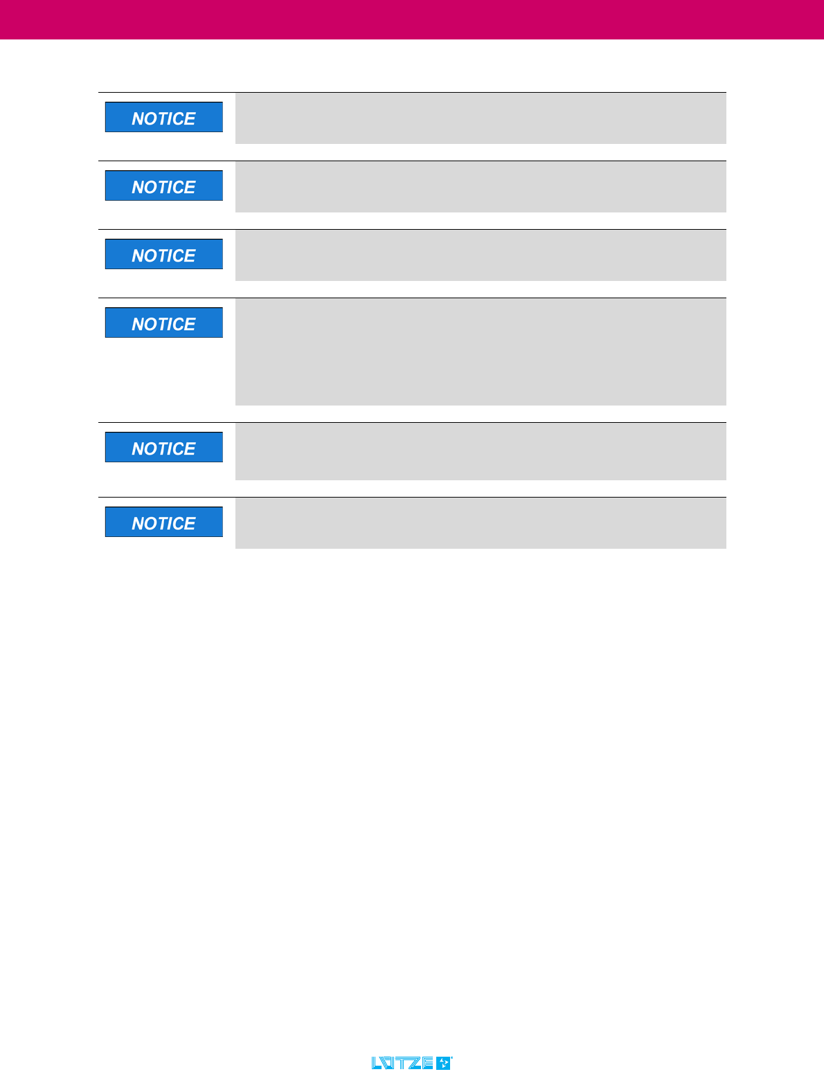
4.1.1 779200.0401 - Unmanaged Switch 4 ports
Abb. 2: 10 / 100 Mbit, auto negotiation, Auto MDI/MDI-X, QoS, unmanaged Switch 4 ports
4.1.2 779200.0801 - Unmanaged Switch 8 ports
Abb. 3: 10 / 100 Mbit, auto negotiation, Auto MDI/MDI-X, QoS, unmanaged Switch 8 ports
4.1.3 779201.0401 - Unmanaged Switch 4 ports
Abb. 4: 10 / 100 Mbit, auto negotiation, Auto MDI/MDI-X, QoS, unmanaged Switch 4 ports
4.1.4 779201.0801 - Unmanaged Switch 8 ports
Abb. 5: 10 / 100 Mbit, auto negotiation, Auto MDI/MDI-X, QoS, unmanaged Switch 8 ports

LCOS Unmanaged Switch ▪ Product Overview
19
TRANSPORTATION
4.2 Overview of product features
4.2.1 LCOS Unmanaged Ethernet Switches
The LCOS-SW-4P or LCOS-SW-8P Unmanaged Ethernet Switch is a switch for
use in industrial environments. It supports ETHERNET 10 MBit/s and Fast
ETHERNET 100 MBit/s.
The switch modules enable the construction of switched Ethernet networks
according to the IEEE 802.3 or 802.3u standard with twisted-pair cables.
The switch modules can be mounted directly on the top-hat rail via a function
carrier and are powered either via the LCOS power bus or the 3-pole connection
terminal. With their compact design, the modules can be mounted in a terminal
box.
The LCOS-SW-4P devices have four 10/100 Mbps twisted pair ports (10/
100BASE-TX, RJ45 connectors) and the LCOS-SW-8P devices have eight 10/
100 Mbps twisted pair ports (10/100BASE-TX, RJ45 connectors).
Twisted pair devices or other TP/TX segments can be connected to the ports. The
TP ports support auto negotiation, auto polarity and auto MDI/MDI-X. In addition,
the devices evaluate the Ethernet frame-based priority data (Qos) in order to
forward time-critical signals more quickly.
The power consumption is significantly reduced by an automatic switch-off of the
unused ports, but even at full load the power consumption of the 8 port version
remains below 2W. The extended operating temperature range allows operation
from - 25 °C to + 70°C ambient temperature.
4.2.2 Product Features of LCOS Unmanaged Ethernet Switches
▪ AC/DC 24V supply voltage
▪ Variable supply voltage supply
- Power bus or
- 3-pole plug-in terminal Push-In
▪ Can be used as a stand-alone module or in the "Lütze Communication
System".
▪ Compact design and universal application
▪ QoS - Quality of Services
▪ Extended temperature range
▪ CE - Declaration of Conformity
▪ UL - Approval
▪ FCC - Approval
LCOS Unmanaged Switch ▪ Product Overview
20
TRANSPORTATION
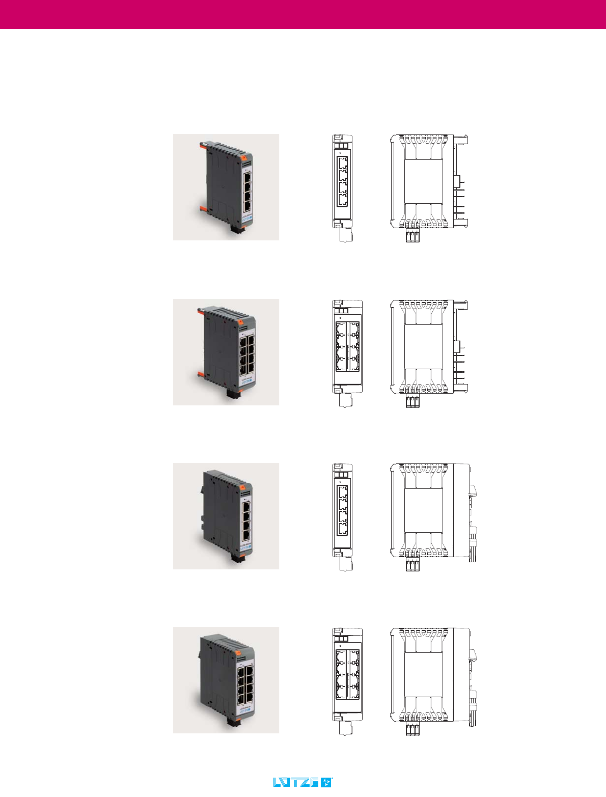
4.2.3 LCOS - Modular housing system
The LCOS Unmanaged Ethernet switches can be used either as a stand-alone
module or in the "Lütze Communication System".
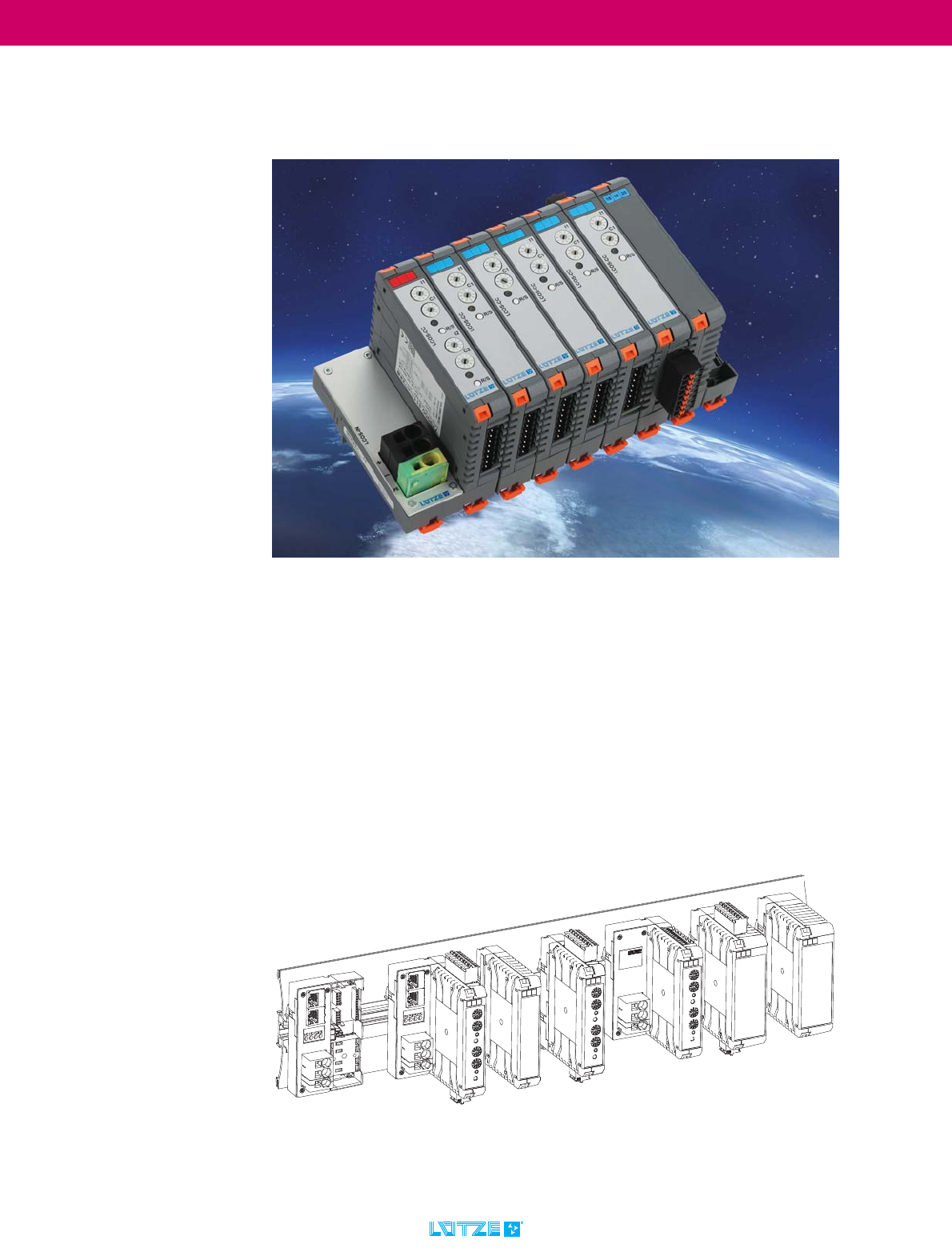
4.2.4 Product description of the modular housing system LCOS
LCOS is a modular housing system consisting of individual modular components
that can be assembled. The functionaries and - housings, as well as various
modules for data and power supply are available in different widths. The housings
can be equipped with their own printed circuit boards as required. Information on
the equipment and size of these can be found in the separately available "LCOS
Modular housing system manual", which is available in the Lütze Online
Catalogue.
A wide variety of front panels and cut-outs on the function housings provide
options for operating elements and a wide variety of plug-in terminals.
In addition, the modules can be bridged and supplied via a feed module so that a
complete system can be set up.
Abb. 6: Overview modular enclosure system, modules not bridged
LCOS Unmanaged Switch ▪ Product Overview
21
TRANSPORTATION
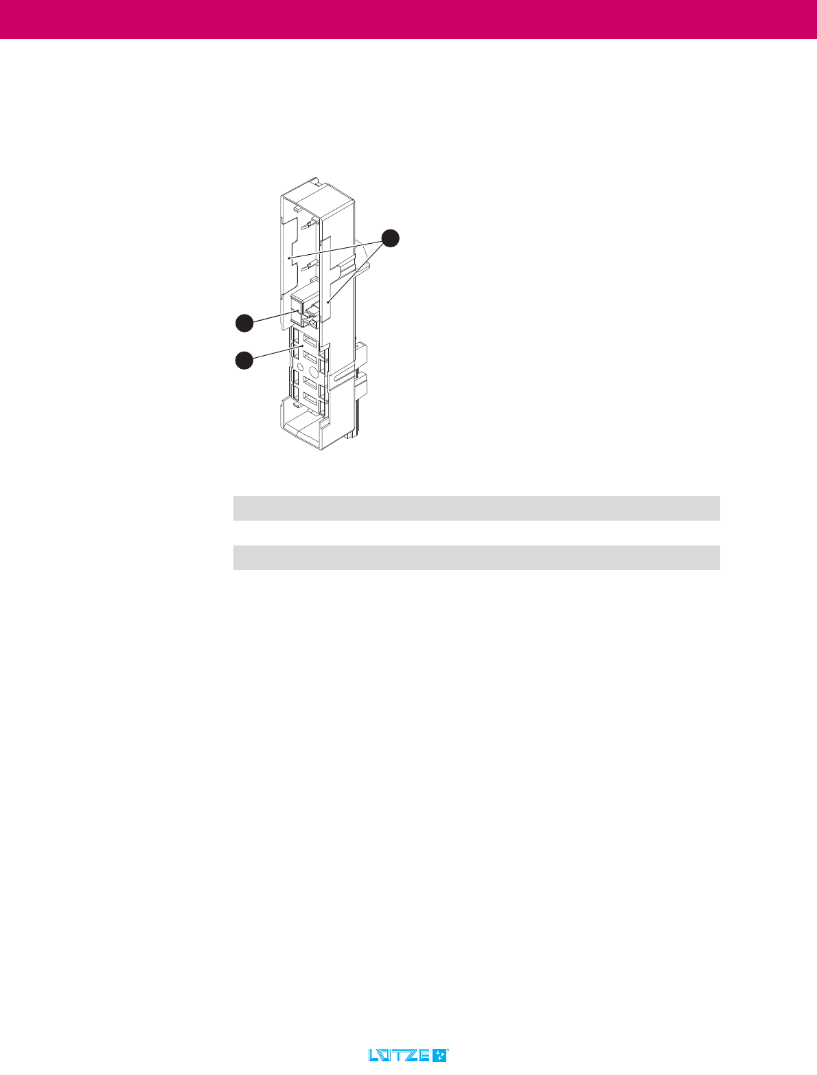
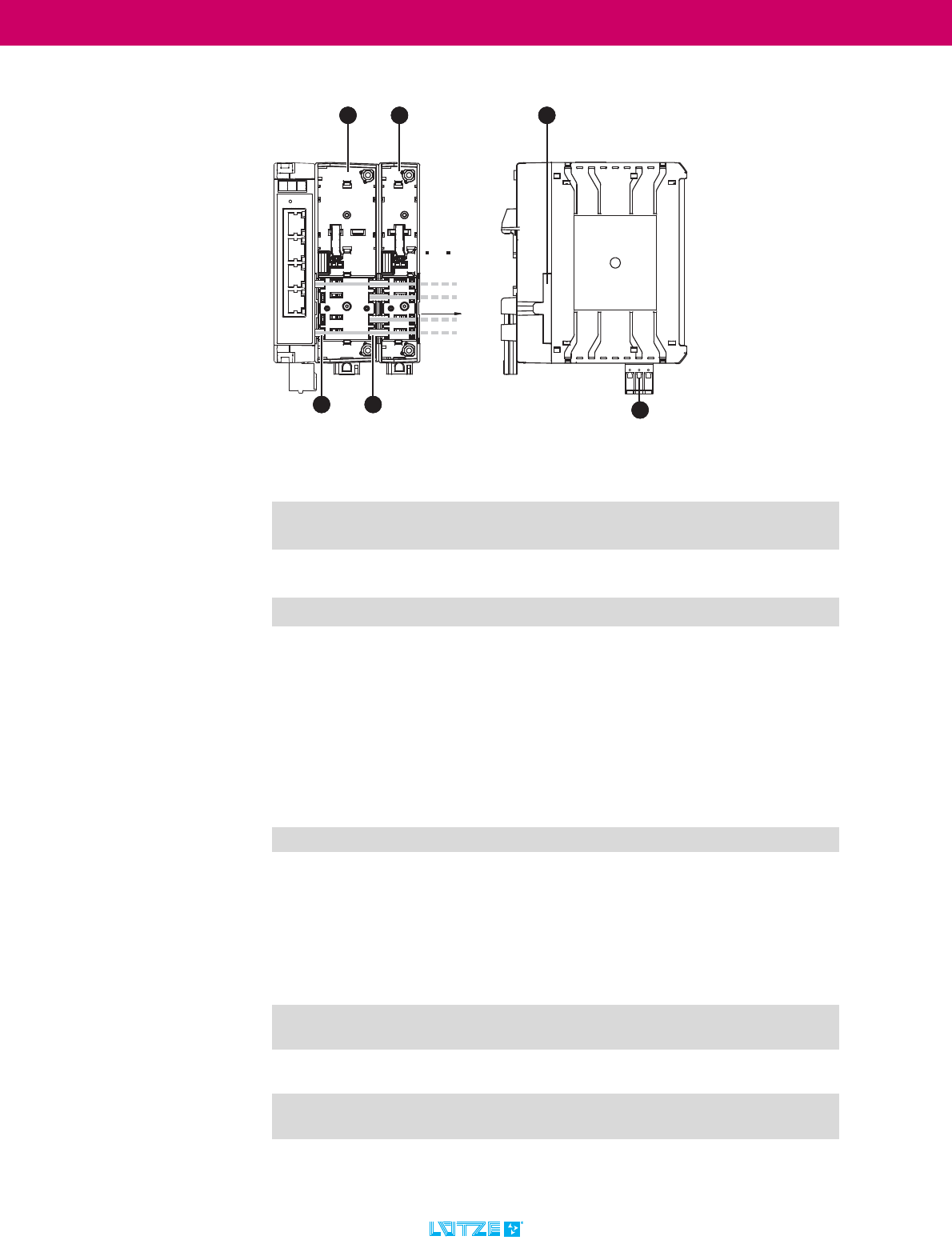
4.3 Function carrier (with power module)
The function carrier is the basis for the LCOS Unmanaged Switch. The LCOS
Unmanaged Switch is plugged onto the function carrier and can then be snapped
onto the DIN rail. The power and data module for setting up the bus system is also
located in the function carrier.
1Power module
2 Labeling Plates
3Side covers
1
2
3
LCOS Unmanaged Switch ▪ Transport and storage
22
TRANSPORTATION
5 Transport and storage
Please note the following:
Proper and safe operation of the products requires proper transport, storage,
installation, assembly, installation, commissioning, operation and maintenance.
Risk of property damage. Risk of damage due to improper handling
during transport and storage.
The device must be protected against moisture, unsafe packaging (mechanical
damage), dust and electrostatic discharge.
Avoid product damage due to incorrect storage conditions.
Protect the equipment from extreme temperatures and humidity. Store
the units in dry rooms between -40 and 85°C. Make sure that the humidity
is less than 75%.
Product damage due to unsafe packaging.
Make sure that the devices are securely packed for transport. This is the only
way to absorb possible shocks.
Product damage caused by dust.
Store and transport the units in a dust-free environment.
Dust can easily settle on the electronic components and lead to a possible
defect of the devices.
Product damage due to electrostatic discharge.
Store and transport electronic components only in an ESD safe environment
and special packaging.
LCOS Unmanaged Switch ▪ Scope of delivery
23
TRANSPORTATION
6 Scope of delivery
Check the completeness of the delivery using the following list.
6.1 The LCOS Unmanaged Switch consists of:
6.1.1 LCOS Unmanaged Switch
1. Device: LCOS Unmanaged (Industrial Ethernet) Switch*
2. Functional support 22.5 mm, not modularly expandable
3. (only for 779201.0401 and 779201.0801)
4. Instruction leaflet (compact operating instructions for the module)
6.1.2 LCOS Unmanaged Switch Documentation
1. Operating instructions (PDF, online version)
2. Data sheets (PDF, online version)
6.2 Accessories
If any of the parts listed below is missing or damaged, please contact the
service department. (chapter „14 Service“ on page 48)
* Part-No. Type Terminati-
on (data)
Included accessories
779200.0401 LCOS-SW-4P 4 x RJ 45
779200.0801 LCOS-SW-8P 8 x RJ 45
779201.0401 LCOS-SW-4P 4 x RJ 45 LCOS-FT-PE-225-00-00-1
779201.0801 LCOS-SW-8P 8 x RJ 45 LCOS-FT-PE-350-00-00-1
You can also find these operating instructions and data sheets at
www.luetze.com.
In the search field, enter either the product name: LCOS Unmanaged Switch
or the product number: 77920*
To avoid malfunctions, only use original accessories.
In the enclosed package insert or corresponding data sheet (online) you
will find the current accessories for the respective product. Depending on
the version of the product, no corresponding function carriers or other
accessories are included in the scope of delivery.
LCOS Unmanaged Switch ▪ Scope of delivery
24
TRANSPORTATION
6.3 Checking the delivery
Check the outer packaging for possible transport damage.
Unpack the product carefully.
▪ Check the package for completeness.
▪ Check the individual parts for transport damage.
Observe ESD regulations when unpacking.
Install and use only undamaged products.
Do not use damaged parts, a function according to the specifications of the
device is then no longer guaranteed.
If damaged parts are used, the following problems may occur:
- Accidents and personal injuries
- Loss of approvals
- Violation of EMC regulations
- Damage to the device and other components
For more information, please contact the service department. (See
chapter „14 Service“ on page 48)
LCOS Unmanaged Switch ▪ Product Assembly
25
TRANSPORTATION
7 Product Assembly
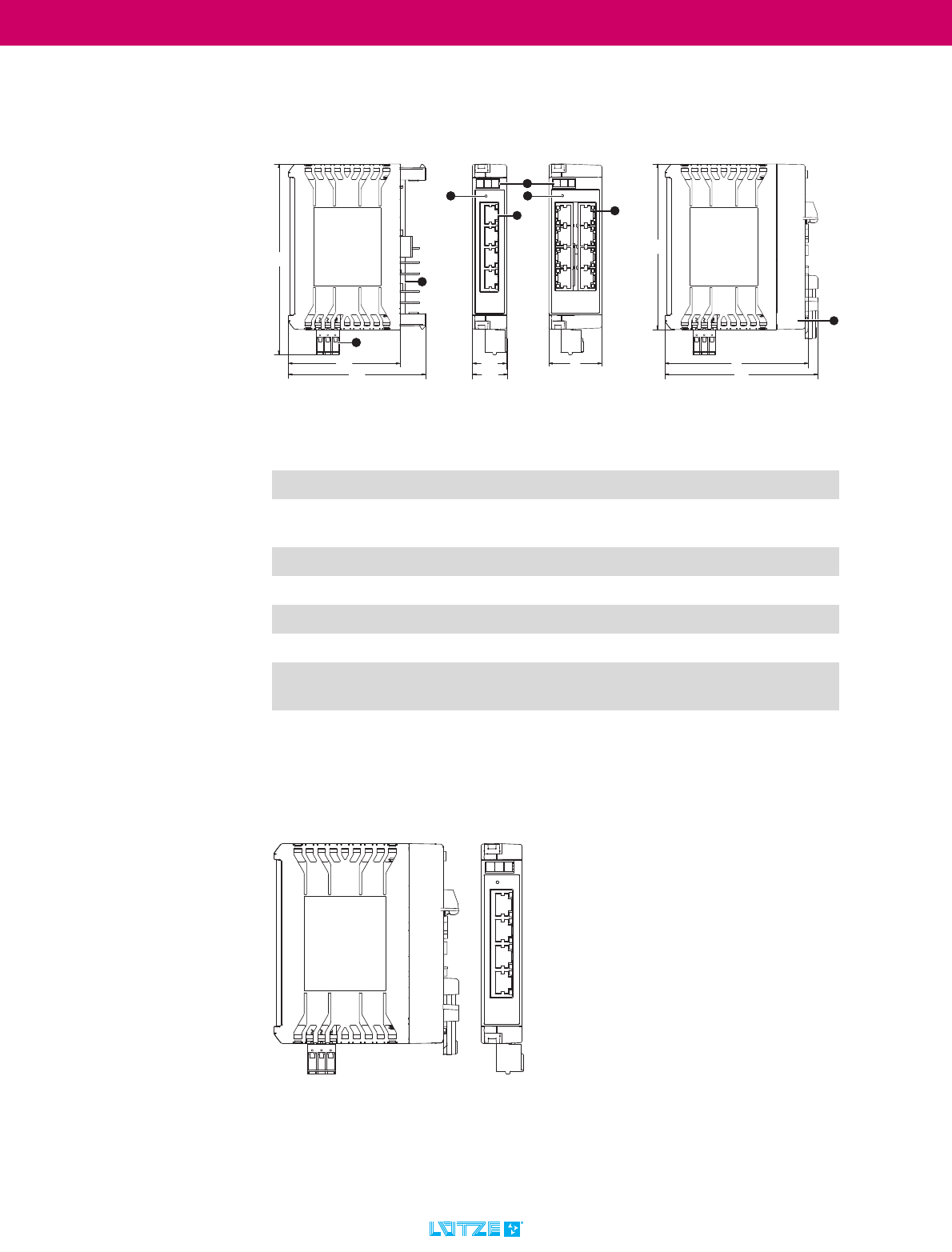
7.1 LCOS Unmanaged Ethernet-Switches
*Not in the scoop of delivery, see chapter „6.2 Accessories“ on page 23.
**Internal connector to LCOS-FT... (power supply)
7.1.1 Standalone Version
No. Description
1Connector X10, 5-pole (internal)**
2 X9: Push-In terminal Power Supply, 3-pole,
RM 5.08
3Labeling Plates*
4 LED power supply
54x Rj45
6 8x Rj45
7Function carrier (only at 779201.0401/
779201.0801 included)
/&266:3/&266:3
LCOS Unmanaged Switch ▪ Product Assembly
26
TRANSPORTATION
7.1.2 System with Powerbus
7.2 LED status displays
7.2.1 LED power supply
7.2.2 LEDs Link/Activity
No. Description
8Function carrier 35 mm, can be expanded with
modules with PE direct contact, power module
9 Function carrier 22.5 mm, can be expanded with
modules with PE direct contact, power module
10 Side cover for function carrier
11 Power bridge 1-pole insulated – 4x per function
carrier
'&3RZHUEXV
Color Status Activity Operating status
green on ON OK – Switch active
off OFF Switch turned off – no/ low supply
voltage
Color Status Activity Operating status
green on link established The port of the switch is connected to
a network subscriber.
off no link is
established
The port of the switch has no
connection to a network subscriber.
blinking active data traffic Data is exchanged on this port of the
switch.

LCOS Unmanaged Switch ▪ Technical Data
27
TRANSPORTATION
8 Technical Data
8.1 Identification
8.2 Description
8.2.1 LCOS-SW-4P
10 / 100 Mbit, auto negotiation, Auto MDI/MDI-X, QoS
4 Fast Ethernet ports, Broadcast storm protection
AC/DC 24 V, extended temperature range
8.2.2 LCOS-SW-8P
10 / 100 Mbit, auto negotiation, Auto MDI/MDI-X, QoS
8 Fast Ethernet ports, Broadcast storm protection
AC/DC 24 V, extended temperature range
8.3 Communication
8.4 Safety
8.5 General
Type: LCOS-SW-4P / LCOS-SW-8P
Part-No.: 779200.0401 / 779200.0801
779201.0401 / 779201.0801
Standard: IEEE 802.3, 802.3u, 802.3x
LAN: 10 / 100 Base-TX
Cable length (segment): max. 100 m
Transfer rate: max. 100 Mbit/s
Connection technology
(data):
4 x RJ45 / 8 x RJ45
Status display
communication:
Link activity
Reverse voltage
protection:
Yes
Isolating voltage Ethernet/
supply/FE
1000 V
Rated voltage UNAC/DC 24 V (SELV, PELV)
Rated frequency 50/60 Hz with AC supply
Operation voltage range AC 19.2–28.8 V / DC 18–31.2 V
Connection technology
(supply)
3-pin terminal clamp, push-in, RM 5.08 or via
LCOS-FT Powerbus
Power consumption 1.5 W
LCOS Unmanaged Switch ▪ Technical Data
28
TRANSPORTATION
Protection class IP20
Over voltage category II
Degree of polution 2
Application height 2000 m
Relative humidity
(operation)
5 % - 95 % (non-condensing)
Relative humidity (storage) 0 % - 95 % (non-condensing)
Operation temperature
range
-25 °C – +70 °C
Storage temperature
range
-40 °C – +85 °C
Dimensions (w × h × d) 35 x 110 x 102 mm
Housing material PA 6.6 (UL 94 V-0, NFF I2, F2)
Mounting connected to LCOS function carrier, hat rail
mounting EN 60715
Installation position vertically
Installation space above: 30 mm (for mounting)
below: 30 mm (for mounting)
sideways: 0 mm
Standards See chapter „2.4 Standards and norms“ on page 7,
compare also current data sheet.
Approvals CE
cULus in preparation
DNV GL in preparation
FCC
(Compare also current data sheet.)
The complete and current technical data can be found in the
corresponding data sheets.
Specifications are subject to change without notice. Make sure you
always work with the latest documents.
Data sheet
779200.0401
Data sheet
779200.0801
Data sheet
779201.0401
Data sheet
779201.0801
You can also find these operating instructions and data sheets at
www.luetze.com.
In the search field, enter either the product name: LCOS Unmanaged Switch
or the product number: 77920*
LCOS Unmanaged Switch ▪ Mounting / Dismounting
29
TRANSPORTATION
9 Mounting / Dismounting
9.1 Installation position
The LCOS Unmanaged Switch, plugged onto an LCOS function carrier, is
mounted vertically on a 35 mm DIN rail (TS 35).
Risk of injury and damage to property from electric current.
Current can injure persons and destroy the modules (assemblies).
▪ Disconnect the system from the power supply before assembly and
disassembly.
With AC supply, an external overvoltage protection must limit the voltage
between supply and VU to less than 1000 V.
For UL applications: Ambient temperature: +70°C
The module must be installed in a fire protection housing suitable for the end
application.
The device is intended to be used in indoor applications and be mounted
in cabinets.
Ensure that the electrical installation complies with local or national
safety regulations.
Observe the minimum distances!
Mount the unit at a distance of at least 30 mm upwards and downwards (0
mm to the side) from other units to ensure proper ventilation.
LCOS Unmanaged Switch ▪ Mounting / Dismounting
30
TRANSPORTATION
9.2 Mounting
The LCOS Unmanaged Switch has protection class IP20 when installed and is
therefore suitable for use in control cabinets. The device is designed to snap onto
/ snap onto a 35 mm DIN rail (also called TS 35 - according to DIN EN 60715).
A top-hat rail is a mounting rail with a U-shaped or hat-like profile. In English the
DIN rail is called DIN rail.
9.2.1 Safety notices Environment
The device may only be installed by competent and qualified personnel.
This work step may only be carried out by at least trained personnel in
compliance with the safety regulations.
The device may only be operated at the specified ambient temperature
and at the specified relative humidity (non-condensing).
Select the mounting location so that the climatic limit values specified in the
technical data are observed.
Use only in an environment up to pollution degree 2 (IEC 60664-1).
LCOS Unmanaged Switch ▪ Mounting / Dismounting
31
TRANSPORTATION
9.2.2 DIN rail mounting
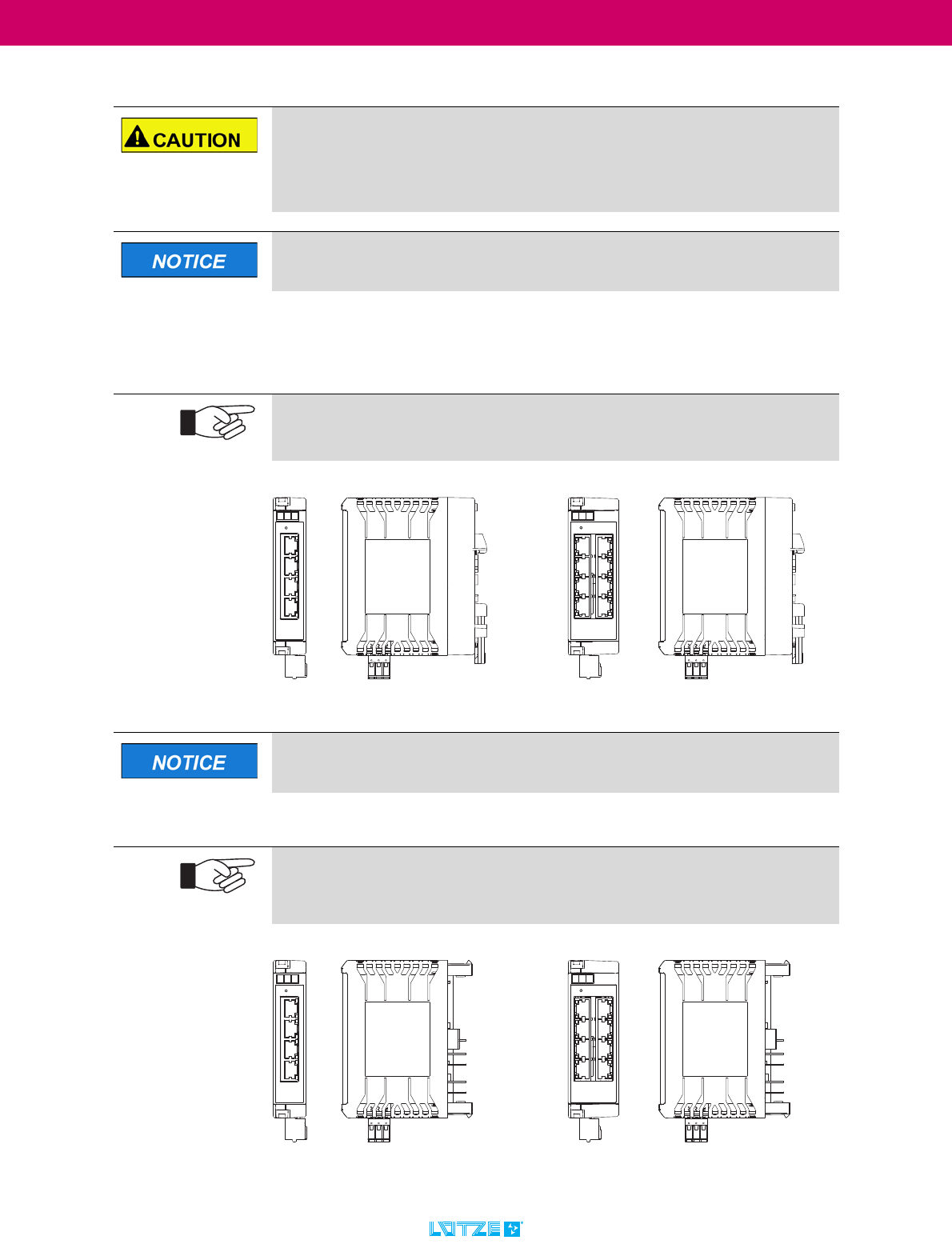
9.2.2.1 Variants of the LCOS Unmanaged Switches
V
Risk of injury and damage to property from electric current.
Current can injure persons and destroy the modules (assemblies).
▪ Disconnect the system from the power supply before assembly and
disassembly.
This step must be carried out by at least trained stuff.
With the variants with function carriers (779201.0401 and 779201.0801),
the switch can be mounted directly on a DIN rail.
The plug-in terminal can be removed for easier wiring.
779201.0401 779201.0801
The variants with function carriers can also be operated on the power bus
by exchanging the function carrier.
The variants without function carriers (779200.0401 and 779200.0801) can
be supplied either via the power bus or the plug-in terminal.
The matching function carrier is available as a separate accessory.
779200.0401 779200.0801
LCOS Unmanaged Switch ▪ Mounting / Dismounting
32
TRANSPORTATION
9.2.2.2 LCOS function carrier
Function carrier 22.5 mm,
Locking slide in open position
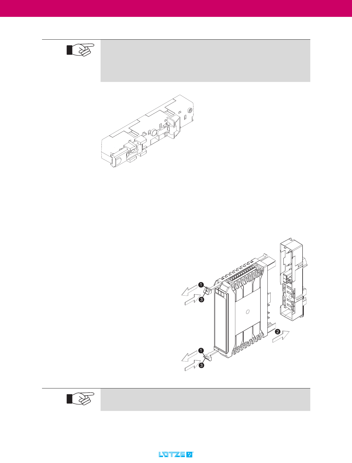
9.2.2.3 Mounting the LCOS housing onto the function carrier*
How you attach the functional housing to the function carrier.
* Function carrier only for 779201.0401 / 779201.0801
included in delivery, see accessories
The function carriers are delivered with open locking slides.
Check the position of the locking slide before mounting the module.The
locking slides of the function carriers are
in open position when delivered.
Check the position of the locking slide before mounting.
1. Pull both pull-tabs as far
as possible.
2. Plug the function housing
onto the function carrier.
3. Push the pull-tabs into the
housing as far as possib-
le.
Remove the functional housing in reverse order.
LCOS Unmanaged Switch ▪ Mounting / Dismounting
33
TRANSPORTATION
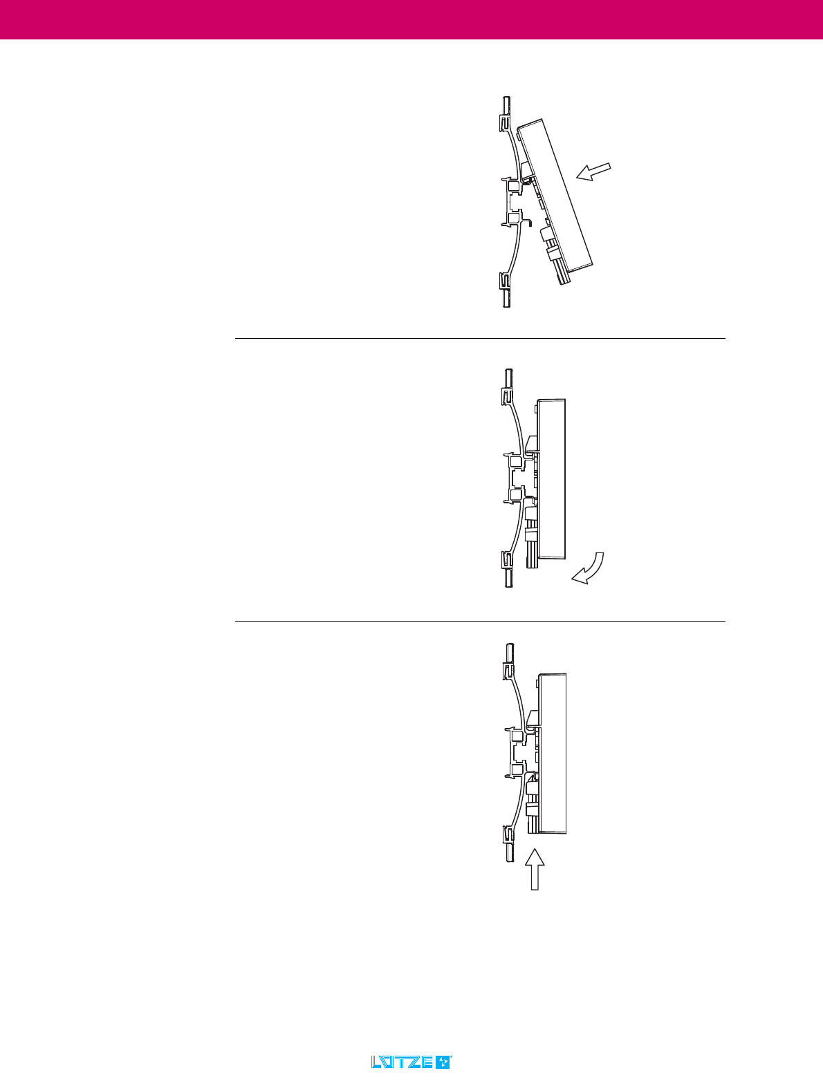
9.2.2.4 Mounting of Function carriers
1. Place the function carrier on the up-
per part of the top hat rail.
2. Pivot the function carrier to the
bottom of the top hat rail.
3. Push the locking slide to the top.The
locking slide is locked.
LCOS Unmanaged Switch ▪ Mounting / Dismounting
34
TRANSPORTATION
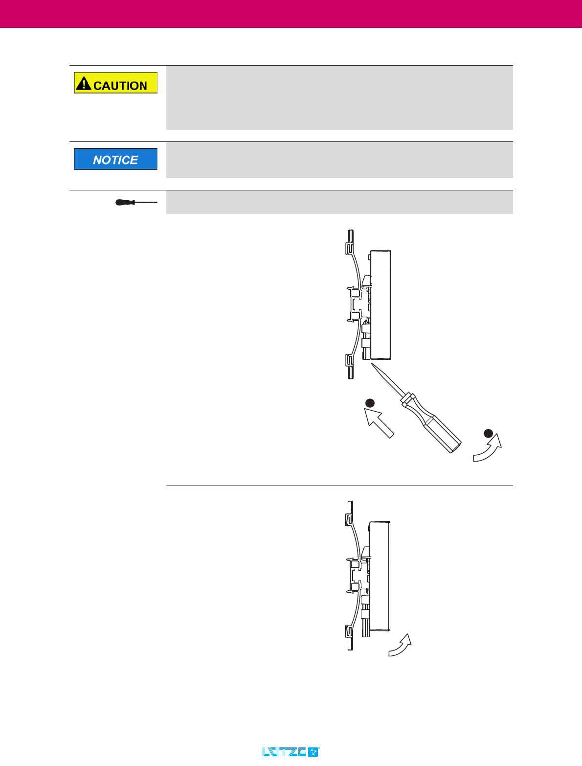
9.2.3 Dismounting of function carriers from top-hat rails
Risk of injury and damage to property from electric current.
Current can injure persons and destroy the modules (assemblies).
▪ Disconnect the system from the power supply before assembly and
disassembly.
This step must be carried out by at least trained staff.
For this step you will need a 3.5 - 4 mm flat-tip screwdriver.
1. Put the screw driver into the notch of
the locking slide.
2. Lever the screw driver up. The
locking slide will unlock.
3. Pivot the function carrier to the top
of the top hat rail.
1
2

LCOS Unmanaged Switch ▪ Mounting / Dismounting
35
TRANSPORTATION
4. Take the function carrier off the top
hat rail.
LCOS Unmanaged Switch ▪ Mounting / Dismounting
36
TRANSPORTATION
9.3 Wiring
9.3.1 Safety notes Shielding ground
The device can be powered by function carrier LCOS-FT... to AC/DC24V,
all voltages must be in conformance to SELV/PELV.
The conductor size has to be selected dependig on the load current and
must be conform with international and national ruls and standards.
Attention! The supply cable must be suitable for an operating
temperature range of -25 °C to +70 °C.
The connecting cables must be designed for the ambient temperature.
To ensure UL certification of the complete module, only use the plug-in
terminals recommended by us.
See also chapter "6.2 Accessories" on page 23)
A screwdriver is required for wiring. (e.g. slotted screwdriver 3 mm)
▪ Push-In terminal
The shielding ground of the connectable twisted-pair cables is electrical-
ly conductively connected to the front panel.
When operating the device via the plug-in terminal, connect the
functional earth (FE) for proper functioning of the device.
When connecting a cable segment with contacted shielding braid, check for
possible ground loops.
Stripping Length Conductor Size
X9: 3-pole
(RM/CS 5.08)
solid 0.08 ... 2.5 mm²
AWG 28 – 12
X9: 3-pole
(RM/CS 5.08)
fine stranded
with ferrule
0.08 ... 2.5 mm²
AWG 28 – 12
10
10
LCOS Unmanaged Switch ▪ Mounting / Dismounting
37
TRANSPORTATION
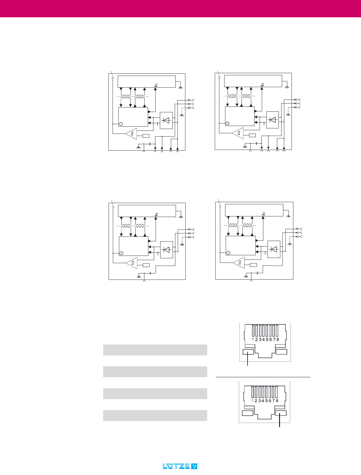
9.4 Pin assignment
X1 ... X8
Pin Color code
wire
Assignment
10BASE-T
100BASE-T
1WHT/ORG TX+
2ORG TX-
3WHT/GRN RX+
4BLU
5WHT/BLU RX-
6GRN
7WHT/BRN
8BRN
$UWLNHO3DUW
/&266:3
;
5;
/('
SRZHUVXSSO\JUHHQ
6:,7&+
(1*,1(
9$&'&*1'
9
/&26)7
'DWD
,VRODWLRQ
;
)( ;
9$&'&
*1'
)(
7;
.9
;;;
[5-
6KLHOG
8PLQ
[/LQN$FWLYLW\
$UWLNHO3DUW
/&266:3
;
5;
/('
SRZHUVXSSO\JUHHQ
6:,7&+
(1*,1(
9$&'&*1'
9
/&26)7
'DWD
,VRODWLRQ
;
)( ;
9$&'&
*1'
)(
7;
.9
;;;
[5-
6KLHOG
8PLQ
[/LQN$FWLYLW\
;;;;
$UWLNHO3DUW
/&266:3
;
5;
/('
SRZHUVXSSO\JUHHQ
6:,7&+
(1*,1(
9
'DWD
,VRODWLRQ
;
)(
9$&'&
*1'
)(
7;
.9
;;;
[5-
6KLHOG
8PLQ
[/LQN$FWLYLW\
$UWLNHO3DUW
/&266:3
;
5;
/('
SRZHUVXSSO\JUHHQ
6:,7&+
(1*,1(
9
'DWD
,VRODWLRQ
;
)(
9$&'&
*1'
)(
7;
.9
;;;
[5-
6KLHOG
8PLQ
[/LQN$FWLYLW\
;;;;
/LQN3RUW6ZLWFK
/LQN3RUW6ZLWFK
LCOS Unmanaged Switch ▪ Mounting / Dismounting
38
TRANSPORTATION
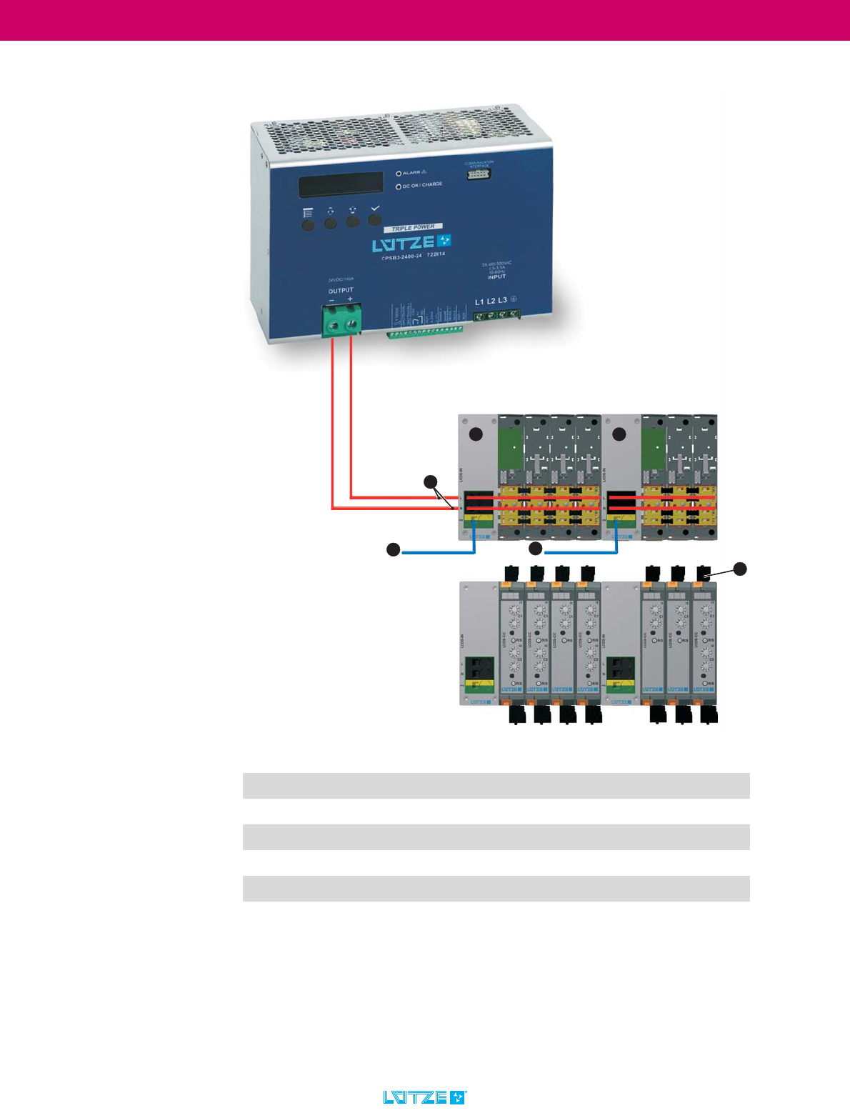
9.5 Further information on the LCOS system (basics)
System configuration
1PE connection
2 Supply voltage
3Supply module
4 Supply module - intermediate supply
5PE connection
6 Load Connection
3
15
6
4
2
LCOS Unmanaged Switch ▪ Mounting / Dismounting
39
TRANSPORTATION
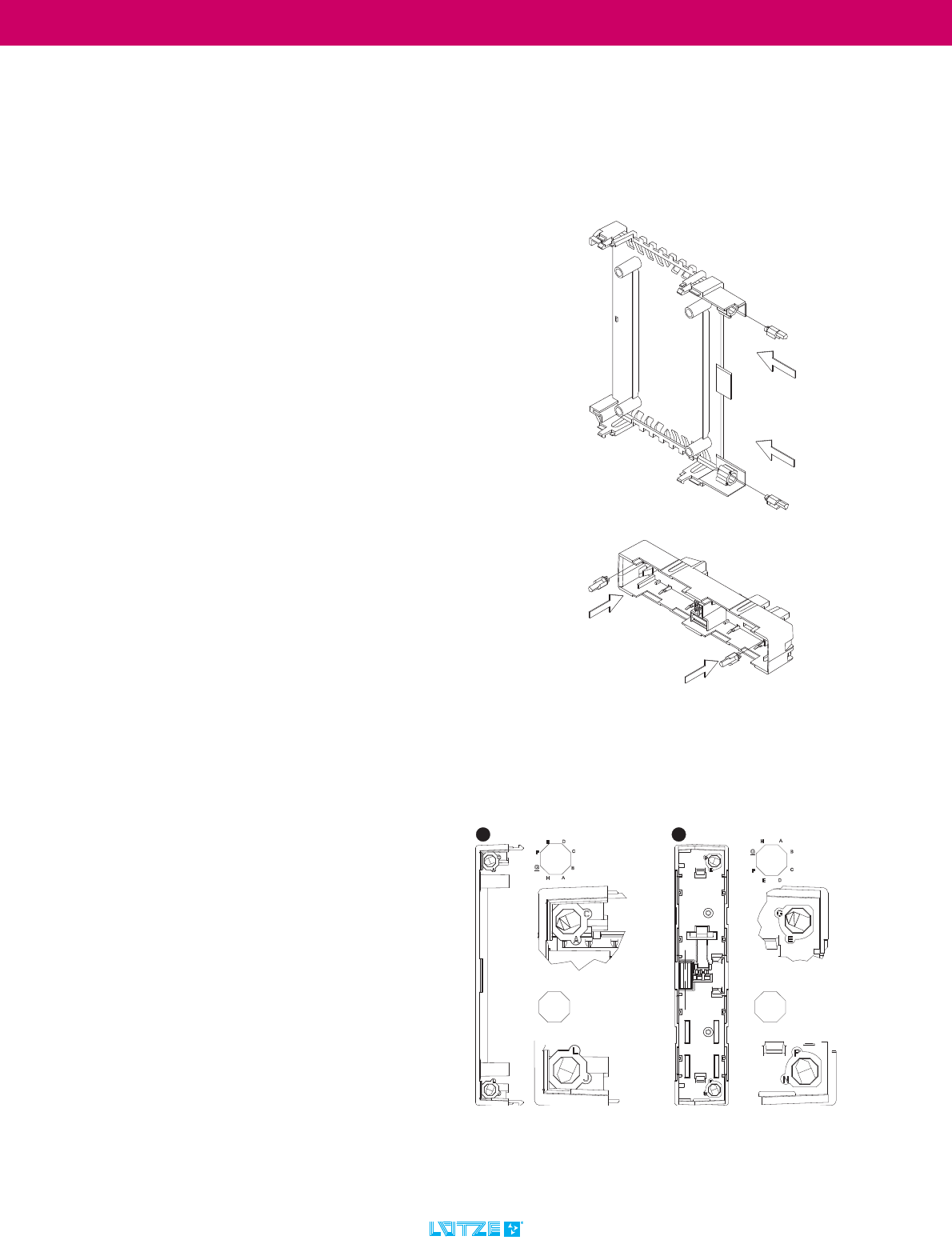
9.6 Coding of LCOS modules
To assign the function housing to the regarding function carrier and also to
prevent mistakes when assembling the modules, the function housing and the
function carrier can be coded.
1. Plug the coding pins into the slots of
the function housing and the carrier.
2. Set the coding pins of the function
housing (1) and the carrier (2) to the
same position.
In the example on the right, position
G was choosen.
J
K
LM
N
O
PI
K
J
IP
O
N
ML
2
1
LCOS Unmanaged Switch ▪ Mounting / Dismounting
40
TRANSPORTATION
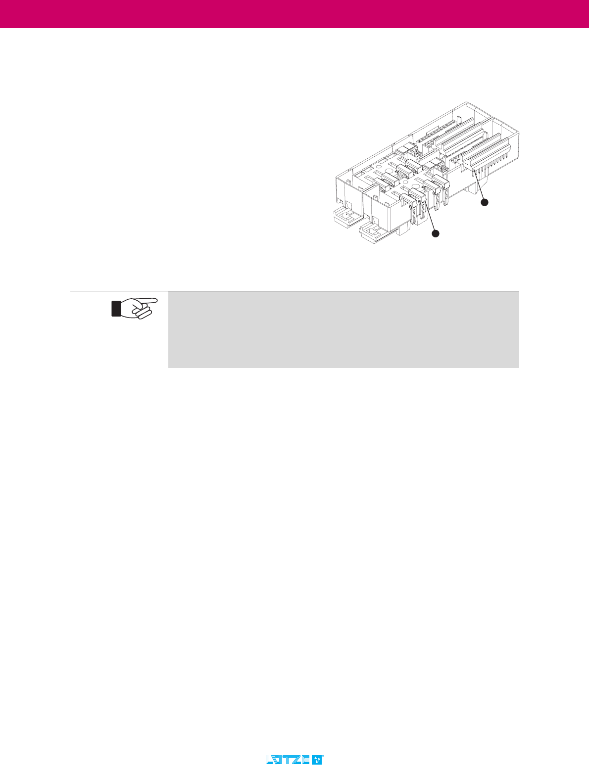
9.7 Installing Data and Power Bridges
In the LCOS system it is possible to bridge single modules.
Connect the modules regarding the
application with
1. a data bridge or
2. a power bridge.
Different combinations are possible.
Two bridged function carriers 22.5 mm,
The carrier to the right is not displayed.
1
2
Further information on the LCOS system can be found at www.luetze.com
In the search field, enter either the product name: LCOS System or this article
number: 780700.575.1
Here you will also find the LCOS System Manual "LCOS Modular housing
system manual" in the download area.
LCOS Unmanaged Switch ▪ Commissioning - Hardware
41
TRANSPORTATION
10 Commissioning - Hardware
10.1 Safety notes Power supply
The supply voltage is galvanically isolated from the housing. The devices can be
supplied either via the energy bus X10 or the connection terminal X9. The power
bus and the connection terminal are internally connected. Polarity is irrelevant.
Commissioning of the hardware may only be carried out by qualified per-
sonnel in compliance with the safety regulations.
Only switch on a device when the housing is closed.
Electric shocks and short-circuits due to incorrect voltage application.
Before commissioning, disconnect the entire system from the power supply and
check the connections after applying power.
The devices may only be connected to the supply voltage printed on the
identification plate.
The devices are designed for operation with safety extra-low voltage.
Accordingly, only SELV/PELV voltage circuits may be connected to the
supply voltage connections.
The earth connection of the device serves exclusively as functional earth
(FE) according to EN 61131-2.
Make sure that peripherals are suitable for the application environment.
The connecting cables must be designed for the ambient temperature.
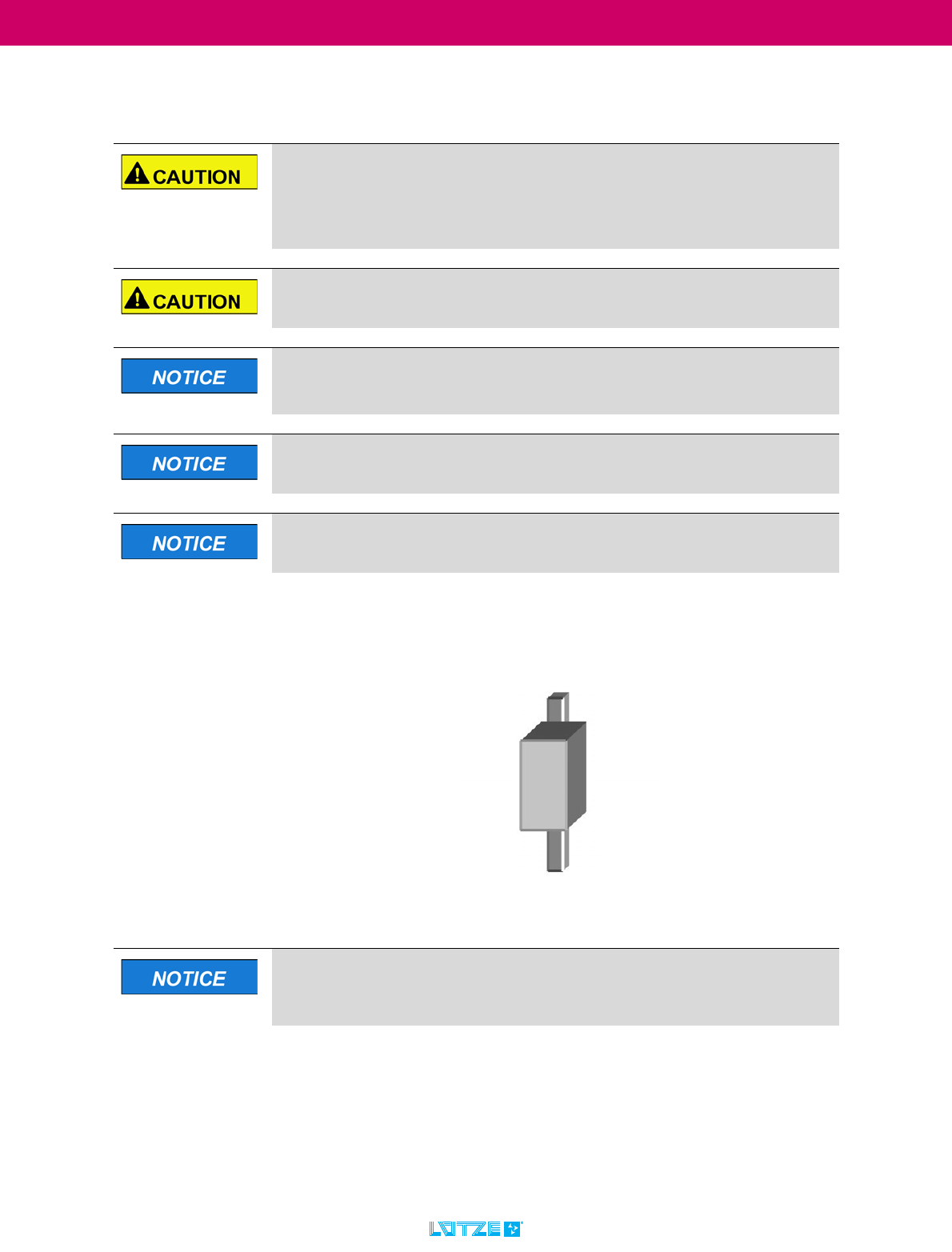
If the switches are supplied with AC, surge voltages of up to 2000 V can
be expected between the active conductors and earth.
However, since the isolation voltage between functional earth (FE) and active
conductors is only 1000 V, external overvoltage protection is required between
the functional earth and at least one active conductor.
This overvoltage protection must limit the voltage to 1000 V.
Varistors of type 7N431K can be used for this purpose, for example.
LCOS Unmanaged Switch ▪ Commissioning - Hardware
42
TRANSPORTATION
10.2 Safety notes Housing
Risk of electric shock!
The housing may only be opened by technicians authorised by Lütze.
The upper and lower ventilation slots must not be covered so that the air
can circulate freely.
The distance to the ventilation slots of the housing must be
at least 30 mm.
Never insert pointed objects (narrow screwdrivers, wires or similar) into
the inside of the product! There is a risk of electric shock.
The housing must be installed in a vertical position.
LCOS Unmanaged Switch ▪ Operation
43
TRANSPORTATION
11 Operation
The device is delivered ready for operation.
11.1 Functional description
The ports of the LCOS Switch represent a terminal device connection for the
connected LAN segment. You can connect individual devices or entire network
segments.
11.2 Frame-Switching functionalities
11.2.1 Store and Forward
All data received by a switch is stored and checked for validity. Invalid and faulty
data packets are discarded. Valid data packets are forwarded. Data packets with
a length of up to 1552 bytes are supported. The packet buffer size is 448k bits.
11.2.2 Multi-address capability
A switch learns all source addresses per port. Only packages with
▪ unknown addresses
▪ these addresses or
▪ a multi-/broadcast address
in the destination address field are sent to this port.
Up to 1000 addresses can be stored simultaneously. This is necessary if more
than one terminal is connected to one or more ports. This allows several
independent subnets to be connected to one switch.
Operation must be carried out by at least trained personnel.
Do not touch the housing during operation or shortly after switching off.
Hot surfaces can cause injuries.
Proper and safe operation of the product requires careful operation and
maintenance.
With the connection of the supply voltage you put the switch into
operation.

LCOS Unmanaged Switch ▪ Operation
44
TRANSPORTATION
11.2.3 Tagging (IEEE 802.1Q)
For the VLAN and prioritisation functions, the IEEE 802.1 Q standard provides
that the VLAN tag is integrated into a MAC data frame. The VLAN tag consists of
4 bytes (2 bytes Tag Protocol Identifier TPID, 2 bytes Tag Control Information
TCI). It is inserted between the source address field and the type field. Data
packets with VLAN tag are transmitted unchanged by the switch.
11.3 Specific functions of the Ethernet interface
11.3.1 Polarity reversal (Auto-Polarity)
If the pair of receiving lines is incorrectly connected (RD+ and RD- reversed), the
polarity is automatically reversed.
11.3.2 Auto MDI-MDIX
The switch detects the transmit and receive line pair. The switch automatically
switches the port output and port input to the corresponding line pairs. Therefore,
it does not matter whether you use a cross-over or uncrossed cable to connect a
device.
11.4 Other functions and features
11.4.1 Undervoltage cutoff
The switch switches off when the voltage falls below a certain level to prevent
malfunctions.
11.5 Display elements
See chapter „7.2 LED status displays“ on page 26.

LCOS Unmanaged Switch ▪ Operation
45
TRANSPORTATION
11.6 Interfaces
11.6.1 10/100 Mbit/s connection (TP Port)
Four (LCOS-SW-4P) or eight (LCOS-SW-8P) ports allow the connection of end
devices or independent network segments according to the IEEE 802.3
100BASE-TX / 10BASE-T standards.
Pin assignment of the RJ45 socket: See chapter „9.4 Pin assignment“ on
page 37.
The unit is to be connected only to internal Ethernet networks without
exiting a facility and being subjected to TNVs.
To avoid electric shock, this device may only be connected to Ethernet
networks within a building that are not connected to TNV circuits. Do not use a
telephone line voltage (TNV)! (This note is particularly relevant for North
America and Canada.)
The input/output connections comply with the Safety Extra Low Voltage (SELV)
guidelines for extra-low voltage devices. With TNV circuits, higher voltages
must be expected, e.g. due to lightning strikes. Therefore, they must not be
connected to SELV circuits.
LCOS Unmanaged Switch ▪ Maintenance - Hardware
46
TRANSPORTATION
12 Maintenance - Hardware
The device is maintenance-free. Therefore, no inspection and maintenance inter-
vals are necessary for ongoing operation. Opening or penetrating the device with
any objects will void the warranty.
For general questions about the product or repair requests, please contact us:
Friedrich Lütze GmbH
Bruckwiesenstraße17-19
71384 Weinstadt
GERMANY / DEUTSCHLAND
Telefon: +49 7151 60530
Telefax: +49 7151 6053277
E-Mail: info@luetze.de
Switch off the input voltage before installation, maintenance or conversi-
on work and secure it against unintentional restarting.
Prevent foreign objects from entering the device, especially metal parts
such as screwdrivers, paper clips or needles, etc.
Do not make any changes or attempt to repair the unit. Do not open the
device!
The replacement of defective hardware must be carried out by qualified
personnel.
In the event of malfunctions or damage, switch off the supply voltage im-
mediately and send the device to the factory for inspection.
The device does not contain any service components.

LCOS Unmanaged Switch ▪ Final Shutdown and Disposal
47
TRANSPORTATION
13 Final Shutdown and Disposal
Mind the valid environmental standards of your country for the final shutdown and
disposal.
For the final shutdown the product has to be disassembled. Electric Parts must
be disposed according to the national electronic scrap regulation. Dispose the
product according to the terms of use and legal liability on your own cost and ex-
empt the Friedrich Lütze GmbH from the responsibilities of §10 passage 2 Elek-
troG (Take-back obligation of the manufacturer) and any third party in this
content.
If the product is handled to a commercial third party without any contractual ac-
ceptance of the disposal, you have to take back the product after the final shut-
down on your own cost and legal liability.
The entitlement of indemnity from the Friedrich Lütze GmbH by the customer
does not prescribe before two years after the final shut down of the product. The
two year deadline of the suspension of statue forlimitations can start with a written
message about the terms from you to the Friedrich Lütze GmbH.

LCOS Unmanaged Switch ▪ Service
48
TRANSPORTATION
14 Service
For general questions about the product or repair requests, please contact us:
Friedrich Lütze GmbH
Bruckwiesenstraße17-19
71384 Weinstadt
GERMANY / DEUTSCHLAND
Telefon: +49 7151 60530
Telefax: +49 7151 6053277
E-Mail: info@luetze.de
The device does not contain any service components.
In the event of malfunctions or damage, switch off the supply voltage im-
mediately and send the device to the factory for inspection.

LCOS Unmanaged Switch ▪ Appendix
49
TRANSPORTATION
15 Appendix
15.1 Overview of other applicable documents
Here is an overview of the other applicable documents for the LCOS Unmanaged
Switches:
15.1.1 LCOS-SW-4P - 4-Port Ethernet Switch - 779200.0401
15.1.2 LCOS-SW-4P - 4-Port Ethernet Switch - 779201.0401
15.1.3 LCOS-SW-8P - 8-Port Ethernet Switch - 779200.0801
1. These operating instructions
2. Data sheet for 779200.0401
3. Type Test Certification for 779200.0401
4. Material Confirmation for 779200.0401
5. CE certification
6. UL certification
7. FCC Test Report
1. These operating instructions
2. Data sheet for 779201.0401
3. Type Test Certification for 779201.0401
4. Material Confirmation for 779201.0401
5. CE certification
6. UL certification
7. FCC Test Report
1. These operating instructions
2. Data sheet for 779200.0801
3. Type Test Certification for 779200.0801
4. Material Confirmation for 779200.0801
5. CE certification
6. UL certification
7. FCC Test Report

LCOS Unmanaged Switch ▪ Appendix
50
TRANSPORTATION
15.1.4 LCOS-SW-8P - 8-Port Ethernet Switch - 779201.0801
15.2 Explanation of abbreviations used
1. These operating instructions
2. Data sheet for 779201.0801
3. Type Test Certification for 779201.0801
4. Material Confirmation for 779201.0801
5. CE certification
6. UL certification
7. FCC Test Report
Acronym Meaning
AC alternating current, term for alternating current, in particular ac-
cording to specifications for alternating voltage
DC the term direct current for direct current; it is also used for di-
rect voltage
DIN The German Institute for Standardization e.V. (DIN) is the most
important national standards organisation in the Federal Repu-
blic of Germany.
ElektroG The Electrical and Electronic Equipment Act (ElektroG) imple-
ments the WEEE directive of the EU on handling electronic wa-
ste in Germany.
EMC Electromagnetic compatibility; it refers to the absence of inter-
ference between electrical or electronic equipment and its en-
vironment.
EN European standard, the standardization of CEN, CENELEC
and ETSI
ESD Electrostatic Discharge - Electrostatic discharges are voltage
punctures caused by large potential differences.
FE Functional earth is often used to install an electrical system in
an electromagnetically compatible manner (EMC). Grounding
one or more points in a network, in a system or in equipment
for purposes other than electrical safety.
IEC International Electrotechnical Commission, a standardization
body for electrical engineering
IEV International Electrotechnical Vocabulary, IEV. The Internatio-
nal Electrotechnical Dictionary is published by the International
Electrotechnical Commission (IEC) to standardize the termino-
logy of electrical engineering. (http://www.electropedia.org/)
IP20 „International Protection“, or „Ingress Protection“), internatio-
nal classification of protection of electrical equipment against
dust and water
LED Light-emitting diode

LCOS Unmanaged Switch ▪ Appendix
51
TRANSPORTATION
Mbit The unit of measurement is called "bit" and has - according to
IEC - "bit" as a unit symbol. Here used for the specification of
data rates e.g. Mbit/s for megabits per second. (Mega stands
for one million).
PE Protective Earth, for protective conductors in electrical en-
gineering
Rx Receiving line
TS 35 DIN rail (35 mm) - DIN rail is a mounting rail with a U-shaped
profile. (The profile resembles a hat.)
Tx Transmission line
ZIP The ZIP file format (zipper) is a format for losslessly compres-
sed files, a data compression format

LCOS Unmanaged Switch ▪ Revision history
52
TRANSPORTATION
16 Revision history
Subject to technical changes. These operating instructions must be kept for
further use!
Revision Description Date
0.00 New document 23/08/2018

© by Friedrich Lütze GmbH, Weinstadt, Germany • Technical changes reserved
www.luetze.com
Deutschland
Friedrich Lütze GmbH
Postfach 1224 (PLZ 71366)
Bruckwiesenstraße 17-19
D-71384 Weinstadt
Tel.: +49 (0)7151 60 53-0
Fax: +49 (0)7151 6053-277(-288)
info@luetze.de
Österreich
LÜTZE Elektrotechnische
Erzeugnisse Ges.m.b.H.
Niedermoserstraße 18
A-1220 Wien
Tel.: +43 (0)1 257 52 52-0
Fax: +43 (0)1 257 52 52-20
office@luetze.at
Schweiz
LÜTZE AG
Oststraße 2
CH-8854 Siebnen/SZ
Tel.: +41 (0)55 450 23 23
Fax: +41 (0)55 450 23 13
info@luetze.ch
USA
LUTZE INC.
info@lutze.com
Großbritannien
LUTZE Ltd.
sales.gb@luetze.co.uk
Frankreich
LUTZE SAS
lutze@lutze.fr
Spanien
LUTZE, S.L.
info@lutze.es
China
Luetze Trading (Shanghai) Co.Ltd
info@luetze.cn
Kabel und Leitungen
Kabelkonfektionierung
Schleppketten
Kabelschutz
Kabelverschraubungen
LSC-Verdrahtungssystem
Modul- und Interfacetechnik
Industrial Ethernet
Entstörtechnik, USV, Power
Supplies
Bahntechnik