Friedrich Racservmn Users Manual Racservmn(7 17 03)_newest.p65
racservmn Room_Air_Service_Manual
2015-02-02
: Friedrich Friedrich-Racservmn-Users-Manual-428497 friedrich-racservmn-users-manual-428497 friedrich pdf
Open the PDF directly: View PDF ![]() .
.
Page Count: 64
Service Manual
Room Air Conditioners
RACServMn (7-03)
2003
2
Introduction
This service manual is designed to be used in conjunction
with the installation manuals provided with each air
conditioning system component.
This service manual was written to assist the professional
RAC service technician to quickly and accurately diagnose
and repair malfunctions.
This manual will deal with subjects in a general nature.
(i.e. all text will not pertain to all models).
IMPORTANT: It will be necessary for you to accurately
identify the unit you are servicing, so you can be certain of
a proper diagnosis and repair. (See Unit Identification.)
The information contained in this manual is intended
for use by a qualified service technician who is
familiar with the safety procedures required in
installation and repair, and who is equipped with the
proper tools and test instruments.
Installation or repairs made by unqualified persons
can result in hazards subjecting the unqualified
person making such repairs to the risk of injury or
electrical shock which can be serious or even fatal
not only to them, but also to persons being served
by the equipment.
If you install or perform service on equipment, you
must assume responsibility for any bodily injury or
property damage which may result to you or others.
Friedrich Air Conditioning Company will not be
responsible for any injury or property damage arising
from improper installation, service, and/or service
procedures.
Table of Contents
Unit Identification ............................................... 3
Unit Specifications ............................................. 4
Unit Performance ......................................... 5-11
Refrigeration Sequence of Operation .............. 12
Electrical Rating Tables ................................... 13
Compressor..................................................... 14
Thermal Overload (External) ........................... 14
Thermal Overload (Internal)............................. 15
Fan Motor ........................................................ 15
System Switches/Controls .......................... 15-24
Thermostats (Indoor) ..................................24-25
Thermostats (Defrost) ................................ 25-26
Resistor (Heat Anticipator) ............................... 26
Capacitor, Run ................................................. 26
Check Valve .................................................... 27
Heat Pump Reversing Valve ............................ 27
Solenoid Coil (Heat Pump Models) .................. 28
Valve, Drain Pan .............................................. 29
Heating Element .............................................. 29
Sealed Refrigeration Repairs ...................... 29-30
Refrigerant Charging .................................. 30-31
Undercharged Refrigerant Systems ........... 31-32
Overcharged Refrigerant Systems .................. 32
Restricted Refrigerant System ......................... 33
Routine Maintenance ....................................... 34
Troubleshooting .......................................... 34-45
Wiring Diagrams
"RS", "RM",................................................... 46
"SQ" ............................................................. 47
"KQ" ........................................................ 48-49
"XQ" ............................................................. 50
"YQ" ............................................................. 51
"SC" ............................................................. 52
"SS", "SM" .................................................... 53
"SL" .............................................................. 54
"KS", "KM", "KL" ........................................... 55
"ES", "EM", "EL", "EK" .................................. 56
"YS13", "YM", "YL" ....................................... 57
"YS09" .......................................................... 58
"EQ" ............................................................. 59
"WS"............................................................. 60
"WE"............................................................. 61
"WY"............................................................. 62
Testing XQ and QME Boards .......................... 63
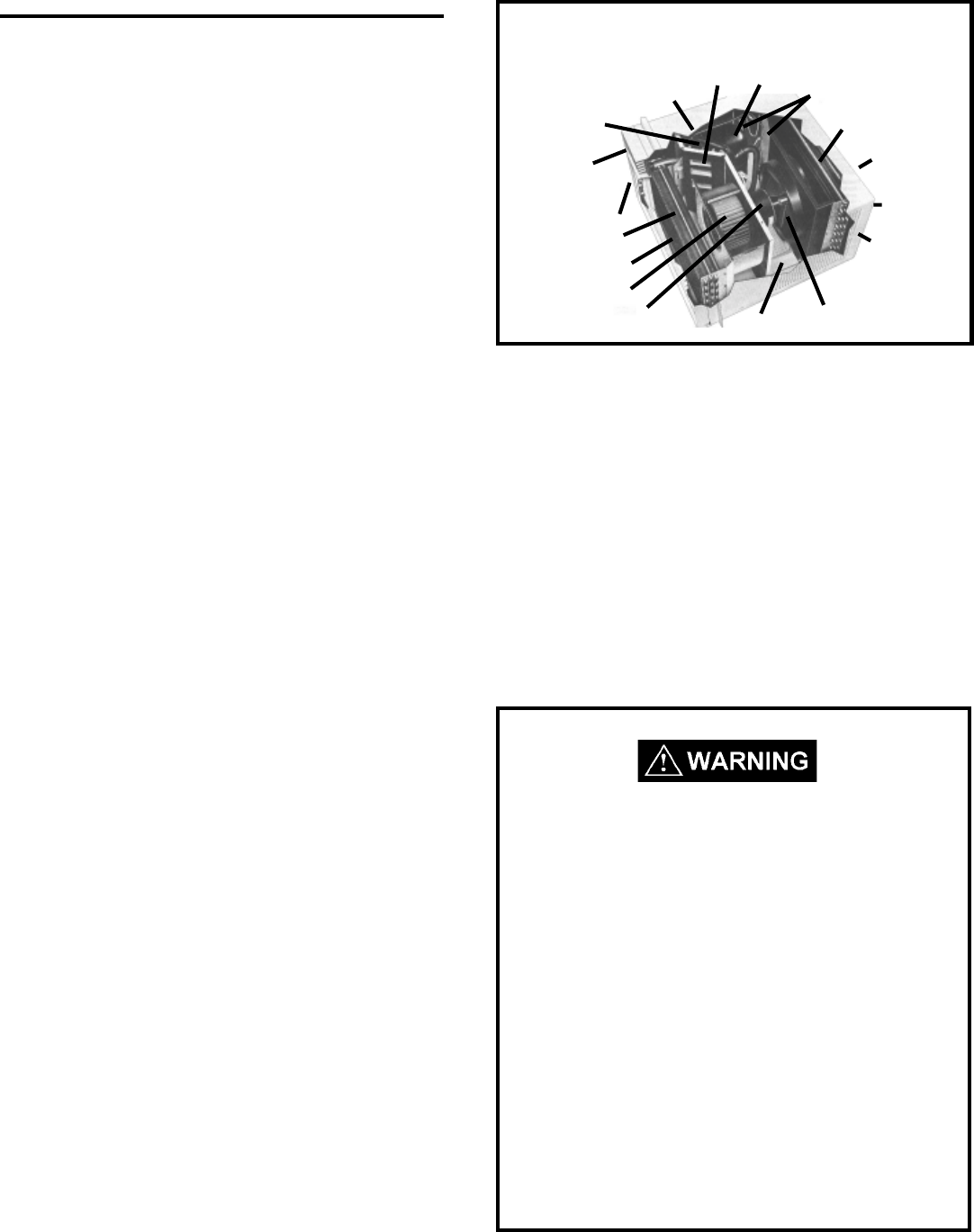
Typical Unit Components
Return Air Grille/Filter
Discharge Air
Evaporator Coil
Blower Wheel
Capillary Tube
Condenser Fan Blade
Outdoor Grille
Sleeve
Condenser Coil
Compressor
Basepan
Front Cover
System Switches
Reversing Valve
(some models)
Fresh Air
Liquid Filter Driers
Blower Motor
3
UNIT IDENTIFICAUNIT IDENTIFICA
UNIT IDENTIFICAUNIT IDENTIFICA
UNIT IDENTIFICATIONTION
TIONTION
TION
Model Number Code
SS08J 1 0 R
1st Digit – Function
S = Straight Cool, Value Series
C = Straight Cool, Budget
Series
Y = Heat Pump
E = Electric Heat
K = Straight Cool, Challenger
Series
W = Thru-the Wall,
WallMaster Series
2nd Digit
C = Casement
P = PowerMiser "Portable"
Q = Q-Star
M = Medium Chassis
L = Large Chassis
W = Built -In
H = HazardGard
3rd and 4th Digit -
Approximate BTU/HR
(Cooling)
Heating BTU/Hr capacity listed in
the Specification/Performance
Data Section
8th Digit – Engineering
Major change
7th Digit – Options
0 = Straight Cool & Heat Pump Models
1 = 1 KW Heat Strip, Normal
3 = 3 KW Heat Strip, Normal
4 = 4 KW Heat Strip, Normal
5 = 5 KW Heat Strip, Normal
8 = 8 KW Heat Strip, Normal
6th Digit – Voltage
1 = 115 Volts
2 = 230 Volts
3 = 230-208 Volts
5th Digit
Alphabetical Modifier
RAC Serial Number Identification Guide
Serial Number
Decade Manufactured
L=0 C=3 F=6 J=9
A=1 D=4 G=7
B=2 E=5 H=8
Year Manufactured
A=1 D=4 G=7 K=0
B=2 E=5 H=8
C=3 F=6 J=9
Month Manufactured
A=Jan D=Apr G=Jul K=Oct
B=Feb E=May H=Aug L=Nov
C=Mar F=Jun J=Sep M=Dec
L C G S 00001
Production Run Number
PRODUCT LINE
S=RAC
P=PTAC
E=EAC
V=VPAK
H=Split
4
5
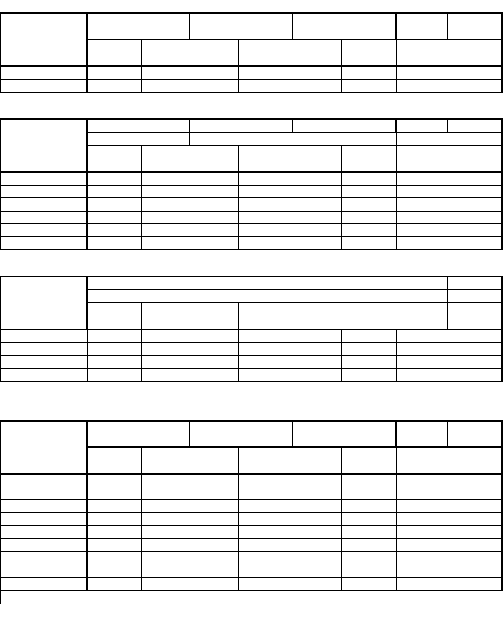
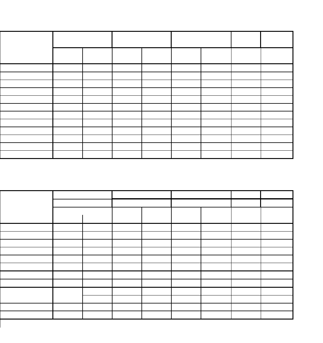
PERFORMANCE R-22 BREAKER
DATA* REFRIG. FUSE
Cooling Discharge Temp. Suction Discharge Amps Locked Charge in 60 Hertz
Air Drop F. Rotar Amp OZ. Amps
EQ08J11-A 50.5 29.5 72 262 7.5 39.2 20 15
EQ08J11-B 50.5 29.5 74 259 7.5 39.2 20 15
DATA* R-22 BREAKER
Cooling REFRIG. FUSE
Discharge Temp. Suction Discharge Amps Locked Charge in 60 Hertz
Air Drop F. Rotar Amp OZ. Amps
XQ05J10B 55.45 24.55 79 245 4.6 34 20 15
XQ06J10-A 51.45 28.55 82 262 5.1 35 21 15
XQ06J10-B 51.45 28.55 79 254 5.1 35 21 15
XQ07J10-1 52.22 27.95 77 250 6.5 37 24 15
XQ08J10-1 50.5 29.5 72 262 4.5 38 20 15
XQ08J10-A 50.5 29.5 72 262 4.5 38 21 15
PERFORMANCE EVAPORATOR AIR ELECTRICAL R-22 BREAKER
DATA* TEMP. DEG. F. RATINGS REFRIG. FUSE
Cooling Discharge Temp. Suction Discharge Amps Locked Charge in 60 Hertz
Air Drop F. Rotar Amp OZ. Amps
SQ05J10B-B 55.45 24.55 79 245 4.4 34.'0 16.'0 15
SQ06J10B-A 51.45 28.55 82 262 5.2 35.'0 15.7 15
SQ06J10B-B 51.45 28.55 79 254 5.2 35.'0 15.7 15
SQ08J10C-1 50.5 29.5 72 262 7.5 39.2 19.5 15
PERFORMANCE R-22 BREAKER
DATA* REFRIG. FUSE
Cooling Discharge Temp. Suction Discharge Amps Locked Charge in 60 Hertz
Air Drop F. Rotar Amp OZ. Amps
KQ05J10B-B 56.34 28.66 73 251 5.2 29.'0 15.'0 15
KQ05E10-B 56.34 28.66 79 245 5.2 29.'0 15.'0 15
KQ05E10-C 56.34 28.66 79 245 5.2 29.'0 15.'0 15
KQ06J10B-A 58.02 21.98 82 262 5.8 35.'0 15.'0 15
KQ06J10B-B 58.02 21.98 80 269 5.8 35.'0 19.'0 15
KQ06E10-A 58.02 21.98 82 262 5.8 35.'0 15.'0 15
KQ06E10-B 58.02 21.98 79 254 5.8 35.'0 15.'0 15
YQ06J10B-A 54.1 25.9 81 267 5.7 39.2 19.'0 15
*Rating Conditions: 80 degree F. Room Air Temperature and 50% Relative Humidity with
95 degree F. Outside Air Temperature and 40% Relative Humitidy
ELECTRICAL
TEMP. DEG. F. PRESSURES RATINGS
EVAPORATOR AIR OPERATING
KQ-YQ PERFORMANCE DATA
SQ PERFORMANCE DATA
EQ PERFORMANCE DATA
EVAPORATOR AIR OPERATING ELECTRICAL
ELECTRICAL
RATINGS
EVAPORATOR AIR
TEMP. DEG. F.
OPERATING
PRESSURES
OPERATING
PRESSURES
XQ PERFORMANCE DATA
TEMP. DEG. F. PRESSURES RATINGS
6
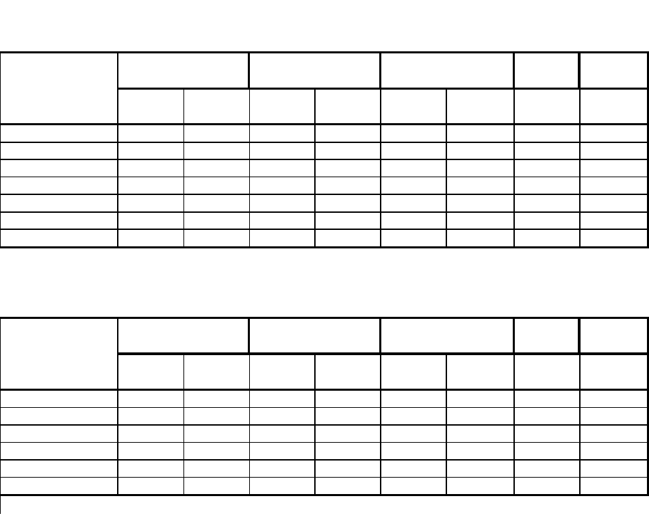
PERFORMANCE R-22 BREAKE
R
DATA* REFRIG. FUSE
Cooling Discharge Temp. Suction Discharge Amps Locked Charge in 60 Hertz
Air Drop F. Rotar Amp OZ. Amps
RS10J10-C 61 19 82 248 7.5 44 26 15
RS12J10A-B 57 23 83 271 9.8 54 30 15
RS15J10-A 57 23 77 279 11.1 42 29.5 15
RS16J30A-A 56.5 24 77 296 7.2 42 30 15
RS18J30-A 56 24 72 293 8.7 42 48 15
RM24J30-A 57 23.65 68 301 12.2 44 54 15
PERFORMANCE R-22 BREAKE
R
DATA* REFRIG. FUSE
Cooling Discharge Temp. Suction Discharge Amps Locked Charge in 60 Hertz
Air Drop F. Rotar Amp OZ. Amps
YS09J10B-A 59 21 90 243 7.7 39.2 25 15
YS12J33-A 56 24 80 264 5.2/5.6 30 28 20
YM18J34B-A 53 27 74 284 8.7/9.2 42 54 30
YL24J35C-A 55 25 72 260 10.0/12.0 61 74 30
* Rating Conditions: 80 degree F. Room Air Temperature and 50% Relative Humidity with
95 degree F. Outside Air Temperature at 40% Relative Humidity.
RS-RM PERFORMANCE DATA
YS-YM-YL PERFORMANCE DATA
EVAPORATOR AIR OPERATING ELECTRICAL
TEMP. DEG. F. PRESSURES RATINGS
ELECTRICAL
RATINGS
EVAPORATOR AIR
TEMP. DEG. F.
OPERATING
PRESSURES
7
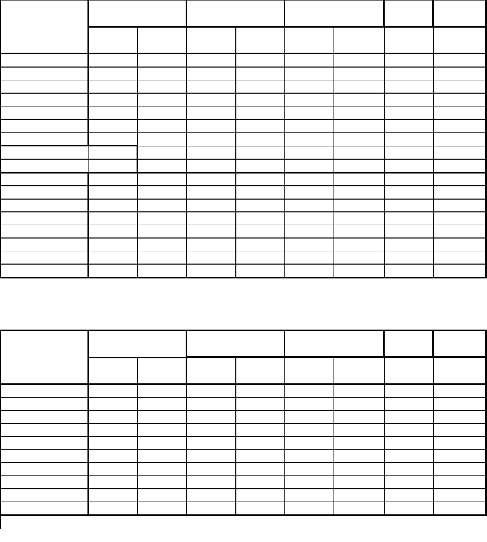
PERFORMANCE R-22 BREAKE
R
DATA* REFRIG. FUSE
Cooling Discharge Temp. Suction Discharge Amps Locked Charge in 60 Hertz
Air Drop F. Rotar Amp OZ. Amps
ES12J33B-A 58 22 82 265 5.76.6 26.3 28 20
ES16J33A-A 53 27 77 269 7.5/8.0 42.'0 30 20
EM18J34B-A 55 25 71 267 8.6/9.2 42.'0 40.5 30
EL25J35-A 55 25 75 284 11.5/12.6 61.'0 48.5 30
EL35J35-A 52 28 72 317 18/20 94.'0 60 30
EL35J35-B 52 28 72 317 18/20 94.'0 60 30
PERFORMANCE Heat Rise
DATA heating
ES12J33B-A 30.5 16/14.7
ES16J33A-A 30.5 16/14.7
EM18J34B-A 28.3 19.5/17
EL25J35-A 28.6 24/22/4
EL35J35-A 22.9 24/22.4
EL35J35-B 22.9 24/22.4
DATA* R-22 BREAKER
Cooling REFRIG. FUSE
Discharge Temp Amps Locked Charge in 60 Herts
Air Drop F. Rotar Amp OZ. Amps
KS10E10-A 61 19 82 248 9.1 48.3 26.08 15
KS10J10-B 61 19 80 263 9.1 48.3 26.88 15
KS12E10-A 57 23 83 271 10.8 54.'0 28 15
KS12J10B-A 57 23 84 268 10.8 54.'0 28 15
KS15J10-A 55.78 23.52 77 279 12.'0 67.'0 29.5 15
KS12J30B-A 57 23 76 285 6.2 26.'0 30.08 15
KS18J30-A 56 24 72 293 8.7 48 48 15
KM20J30-A 55 24 70 279 9.9 48 48 15
KM24J30-A 55 25 68 301 15.'0 71.'0 54.08 15
* Rating Conditions: 80 degree F. Room Air Temperature and 50% Relative Humidity with
95 degree F. Outside Air Temperature at 40% Relative Humidity.
KS-KM PERFORMANCE DATA
EVAPORATOR AIR OPERATING ELECTRICAL
ELECTRICAL
RATINGS
EVAPORATOR AIR
TEMP. DEG. F.
OPERATING
PRESSURES
TEMP. DEG. F. PRESSURES RATINGS
8
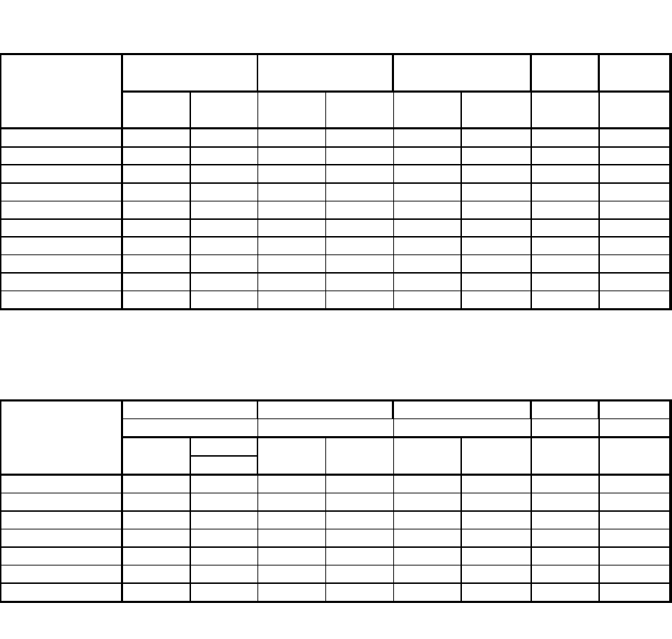
PERFORMANCE R-22 BREAKE
R
DATA* REFRIG. FUSE
Cooling Discharge Temp. Suction Discharge Amps Locked Charge in 60 Hertz
Air Drop F. Rotar Amp OZ. Amps
SS08J10R-B 61.4 18.6 87 251 6.7 29 39.'0 15
SS08J10R-A 61.4 18.6 84 248 6.7 36.2 24.'0 15
SS09J10C-A 57.8 22.2 82 254 7.4 44 22.6 15
SS10J10AR-A 57.22 22.78 84 245 7.5 42 26.'0 15
SS12J10AR-B 57.2 22.8 83 271 9.8 44 30.'0 15
SS14J10R-A 57.22 22.9 77 279 12 61 29.5 15
SS12J30D-A 57.2 22.8 82 265 5.0/5.2 21 27.5 20
SS16J30A-A 56.9 23 77 296 7.5/8.0 28 30.'0 20
SS18J30R-A 56.9 23 77 293 8.1/8.7 45 48 20
PERFORMANCE R-22 BREAKE
R
DATA* REFRIG. FUSE
Cooling Discharge Temp Suction Discharge Amps Locked Charge in 60 Hertz
Air Drop F. Rotar Amp OZ. Amps
SM20J30-A 52.58 27.42 70 279 9.9 43 47 20
SM24J30-A 54.86 25.14 68 301 12.2 68 54 20
SL25J30-A 52.32 27.68 75 284 11.5/12.6 68 48.5 20
SL28J30B-A 52.1 26.9 74 278 13.0/14.2 88 50 20
SL35J30-A 52.93 27.07 72 317 18.0/20.0 92 60 30
SL35J30-B 52.93 27.07 72 317 18.0/20.0 92 60 30
* Rating Conditions: 80 degree F. Room Air Temperature and 50% Relative Humidity with
95 degree F. Outside Air Temperature at 40% Relative Humidity.
SS PERFORMANCE DATA
SM-SL PERFORMANCE DATA
EVAPORATOR AIR OPERATING ELECTRICAL
ELECTRICAL
RATINGS
EVAPORATOR AIR
TEMP. DEG. F.
OPERATING
PRESSURES
TEMP. DEG. F PRESSURES RATINGS
9
PERFORMANCE R-22 BREAKER
DATA* REFRIG. FUSE
Cooling Discharge Temp. Suction Discharge Amps Locked Charge in 60 Hertz
Air Drop F. Rotar Amp OZ. Amps
WS07A10E-B 59.5 19.5 84 300 7.'0 32 19 15
WS07A10E-C 59.5 19.5 85 299 7.'0 32 28 15
WS07A10E-D 59.5 19.5 85 299 7.'0 32 20 15
WS10A10-A 58 22 83 307 9.8 48 25 15
WS10A10-B 58 22 83 307 9.8 48 26 15
WS12A10E-B 55 25 81 290 11.9 54 28.5 15
WS13A10-A 55 25 79 281 12 55 36 15
WS09A30E-B 58 22 86 302 4.7 44 22 15
WS12A30E-A 47.1 32.9 80 308 11.9 54 27.5 15
WS12A30E-B 46 33 80 305 11.9 54 42 15
WS15A30-A 47 33 72 310 8.5 42 43.5 15
DATA* R-22 BREAKER
Cooling REFRIG. FUSE
Discharge Temp. Suction Discharge Amps Locked Charge in 60 Hertz
Air Drop F. Rotar Amp OZ. Amps
WE09A33E-C 58 22 86 302 4.7 44 23 20
WE12A33E-B 55 25 80 308 6.5 54 27.5 20
WE15A33-A 47.1 32.9 71 310 8.5 42 43.5 20
WY09A33F-A 58 22 83 288 4.3 44 24 20
WY12A33G-A 55 25 81 295 6.2 54 37 20
PERFORMANCE Heat Rise
DATA heating
WE15A33-A 40 16.2
WE09A33E-C 39 14.7
WE12A33E-B 36 14.7
* Rating Conditions: 80 degree F. Room Air Temperature and 50% Relative Humidity
95 degree F. Outside Air Temperature at 40% Relative Humidity
WS PERFORMANCE DATA
WE-WY PERFORMANCE DATA
EVAPORATOR OPERATION ELECTRICAL
ELECTRICAL
RATINGS
EVAPORATOR AIR
TEMP. DEG. F.
OPERATING
PRESSURES
TEMP. DEG. F. PRESSURES RATINGS
10
PERFORMANCE DATA *YS09J10B-A **YS12J33-A **YM18J34A-A **YL24J35C-A
(Heating)
AHAM @ 70°F Inside 47°F Outside 8300 12400/12300 17200/17200 23000/22800
@ 70°F Inside 35°F Outside 10700/8900 13000/10600 17300/14300
Evaporator Air Temperature Rise
@ 70°F Inside 47°F Outside 19.62 31.38 24.74 31.71
@ 70°F Inside 35°F Outside 28.69/23.87 24.46/20.22 24.38/20.16
AMPS @ 70°F Inside 47°F Outside 6.7 6.0/6.5 8.5/9.0 10.4/11.5
@ 70°F Inside 35°F Outside 16.0/14.7 19.5/17.0 24.0/22.4
Watts @ 70°F Inside 47°F Outside 760 1340/1300 1880/1820 2350/2340
@ 70°F Inside 35°F Outside 3500/2900 5500/4650 5500/4650
Suction/Head PSIG
@ 70°F Inside 47°F Outside 53.5/222 52.5/251 53/225 54/236.5
* Do not operate below 37° ambient.
** Heating element comes on at 35°F outside ambient and compressor shuts off.
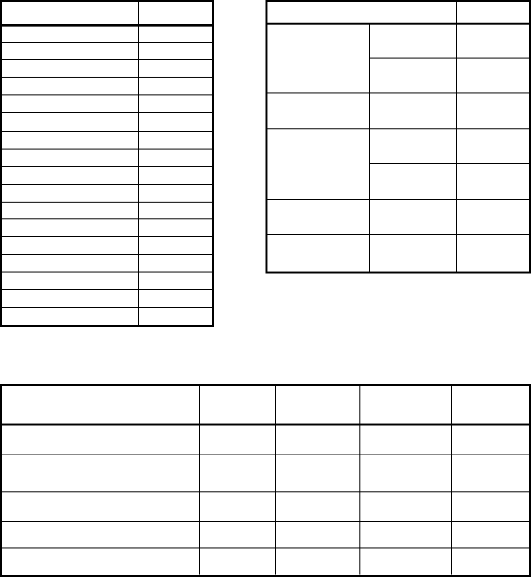
SPECIFICATIONS SC06H10E
BTUH (Cooling) 5950
E.E.R. (Cooling) 8.0
Volts 115
Amperes (Cooling) 6.8
Total Watts (Cooling) 760
Hertz 60
Fuse/Breaker Size 15
Fan RPM 1595
Evaporator Air CFM 125
Dehumidification Pts/Hr 2.0
Width 1411/16"
Height 1013/16"
Depth 27"
Minimum Ext. Into Room 2½"
Minimum Ext. To Outside 15½"
Net Weight 70
Shipping Weight 80
PERFORMANCE DATA* SC06H10E
DISCHARGE 56.1
EVAPORATOR AIR AIR
TEMP. °F TEMP 23.9
DROP °F
OPERATING SUCTION 72
PRESSURES DISCHARGE 293
AMPS 6.8
ELECTRICAL
RATINGS LOCKED 35.0
ROTOR AMPS
R-22 CHARGE IN 14
REFRIG. OUNCES
COMP. CHARGE IN 9.8
OIL FLUID OZ.
* Rating Conditions:
80°F Room Air Temperature and 50% Relative Humidity with
95°F Outside Air Temperature at 40% Relative Humidity.
11
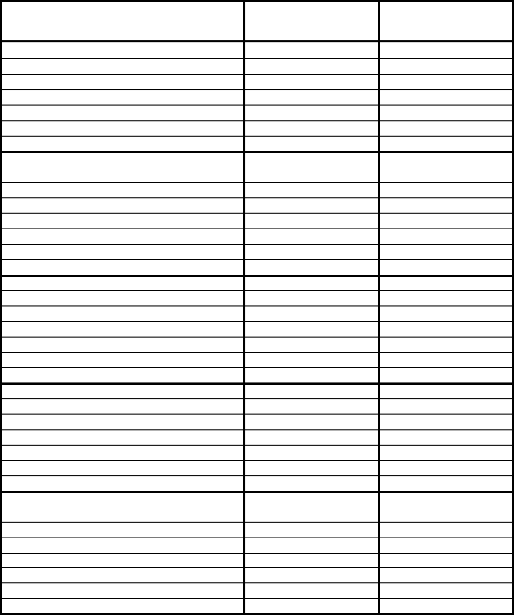
PERFORMANCE DATA *WY09A33F-A *WY12A33F-A
(Heating)
BTUH @70°F Inside 62°F Outside 9700 12400
@70°F Inside 57°F Outside 9300 12000
@70°F Inside 52°F Outside 8800 11400
** @70°F Inside 47°F Outside 8200/8100 10800/10400
@70°F Inside 42°F Outside 7600 10000
@70°F Inside 37°F Outside 6800 9000
@70°F Inside 35°F Outside 11000/9100 11000/9100
Evaporator Air Temperature Rise
@70°F Inside 62°F Outside 32.00 37.60
@70°F Inside 57°F Outside 30.75 36.40
@70°F Inside 52°F Outside 29.10 34.50
** @70°F Inside 47°F Outside 27.10/26.80 32.70/31.50
@70°F Inside 42°F Outside 25.10 30.30
@70°F Inside 37°F Outside 22.50 27.30
@70°F Inside 35°F Outside 36.40/30.10 33.30/27.60
AMPS @70°F Inside 62°F Outside 4.0 5.6
@70°F Inside 57°F Outside 3.9 5.5
@70°F Inside 52°F Outside 3.85 5.4
** @70°F Inside 47°F Outside 3.8/4.1 5.3/5.6
@70°F Inside 42°F Outside 3.6 5.1
@70°F Inside 37°F Outside 3.4 4.8
@70°F Inside 35°F Outside 16.0/14.7 16.0/14.7
Watts @70°F Inside 62°F Outside 880 1280
@70°F Inside 57°F Outside 870 1260
@70°F Inside 52°F Outside 860 1220
** @70°F Inside 47°F Outside 835/810 1175/1155
@70°F Inside 42°F Outside 800 1130
@70°F Inside 37°F Outside 760 1070
@70°F Inside 35°F Outside 3550/2950 3550/2950
Suction/Head PSIG
@70°F Inside 62°F Outside 66/315 61/325
@70°F Inside 57°F Outside 62/285 59/290
@70°F Inside 52°F Outside 57/285 53/275
** @70°F Inside 47°F Outside 53/265 49/255
@70°F Inside 42°F Outside 49/215 45/240
@70°F Inside 37°F Outside 45/203 41/220
@70°F Inside 35°F Outside 44/200 40/215
* Heating Element comes on at 35°F outside ambient and compressor shuts off.
** AHAM Rating Conditions.
12
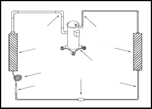
A good understanding of the basic operation of the refrigeration
system is essential for the service technician. Without this
understanding, accurate troubleshooting of refrigeration
system problems will be more difficult and time consuming, if
not (in some cases) entirely impossible. The refrigeration
system uses four basic principles (laws) in its operation they
are as follows:
1. "Heat always flows from a warmer body to a cooler body."
2. "Heat must be added to or removed from a substance
before a change in state can occur"
3. "Flow is always from a higher pressure area to a lower
pressure area."
4. "The temperature at which a liquid or gas changes state
is dependent upon the pressure."
The refrigeration cycle begins at the compressor. Starting
the compressor creates a low pressure in the suction line which
draws refrigerant gas (vapor) into the compressor. The
compressor then "compresses" this refrigerant, raising its
pressure and its (heat intensity) Temperature.
The refrigerant leaves the compressor through the discharge
line as a hot high pressure gas (vapor). The refrigerant enters
the condenser coil where it gives up some of its heat. The
condenser fan moving air across the coil's finned surface
facilitates the transfer of heat from the refrigerant to the
relatively cooler outdoor air.
When a sufficient quantity of heat has been removed from
the refrigerant gas (vapor), the refrigerant will "condense" (i.e.
change to a liquid). Once the refrigerant has been condensed
(changed) to a liquid it is cooled even further by the air that
continues to flow across the condenser coil.
The RAC design determines at exactly what point (in the
condenser) the change of state (i.e. gas to a liquid) takes place.
In all cases, however, the refrigerant must be totally condensed
(changed) to a liquid before leaving the condenser coil.
The refrigerant leaves the condenser coil through the liquid line
as a warm high pressure liquid. It next will pass through the
refrigerant drier (if so equipped). It is the function of the drier to
trap any moisture present in the system, contaminants, and large
particulate matter.
The liquid refrigerant next enters the metering device. The metering
device is a capillary tube. The purpose of the metering device is to
"meter" (i.e. control or measure) the quantity of refrigerant entering
the evaporator coil.
Refrigeration SystemRefrigeration System
Refrigeration SystemRefrigeration System
Refrigeration System
Sequence of OperationSequence of Operation
Sequence of OperationSequence of Operation
Sequence of Operation
Liquid
Line
Suction
Line
Evaporator
Coil
Metering
Device
Refrigerant
Dryer
Discharge
Line
Refrigerant
Drier
Condenser
Coil
Compressor
In the case of the capillary tube this is accomplished (by design)
through size (and length) of device, and the pressure difference
present across the device.
Since the evaporator coil is under a lower pressure (due to the
suction created by the compressor) than the liquid line, the liquid
refrigerant leaves the metering device entering the evaporator coil.
As it enters the evaporator coil, the larger area and lower pressure
allows the refrigerant to expand and lower its temperature (heat
intensity). This expansion is often referred to as "boiling". Since
the unit's blower is moving Indoor air across the finned surface of
the evaporator coil, the expanding refrigerant absorbs some of
that heat. This results in a lowering of the indoor air temperature,
hence the "cooling" effect.
The expansion and absorbing of heat cause the liquid refrigerant
to evaporate (i.e. change to a gas). Once the refrigerant has
been evaporated (changed to a gas), it is heated even further by
the air that continues to flow across the evaporator coil.
The particular system design determines at exactly what point (in
the evaporator) the change of state (i.e. liquid to a gas) takes
place. In all cases, however, the refrigerant must be totally
evaporated (changed) to a gas before leaving the evaporator coil.
The low pressure (suction) created by the compressor causes the
refrigerant to leave the evaporator through the suction line as a
cool low pressure vapor. The refrigerant then returns to the
compressor, where the cycle is repeated.
13
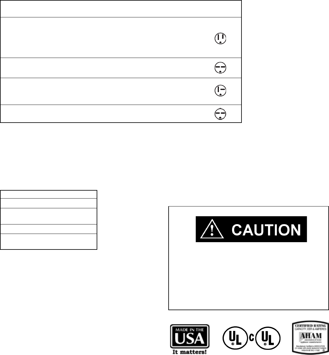
Circuit Rating Plug Face Appearance
Model Breaker or T-D Fuse (NEMA#) (Facing Blades)
ALL SV and XQ MODELS,
KS10J10, KS12J10B, KS15J10, RS10J10, RS12J10A,
RS15J10, SS08J10R, SS09J10C, SS10J10AR,
SS12J10AR, SS14J10R, SC06H10D, 125V - 15A 5 - 15P
EQ08J11, YQ06J10B, YS09J10B
KS12J30B, KM18J30C, RS16J30A,
RM18J30A, SS12J30D, SS16J30A, SM18J30BR 250V - 15A 6 - 15P
KM20J30, KM24J30, SM20J30,
SL25J30, SL28J30B*, ES12J33B, 250V - 20A 6 - 20P
ES16J33A, YS12J33
SL35J30, EM18J34B, EL25J35, EL35J35,
YM18J34B, YL24J35C 250V - 30A 6 - 30P
* Optional 30 Amp Kit (618-869-00) is recommended in 208 Volt power supply areas that fall below 208 Volts.
For more information, call the Friedrich Service Department.
Due to a program of continuing improvement, specifications are subject to change without notice.
Installation Notes:
Supply Cord - All with right angle plug 6' on 115V; 5' on 230/208V.
Room air conditioners include accessories for window or thru-the-wall installation.
TWINTEMP® models include accessories for thru-the-wall installation only.
Window mounting requires use of optional accessory kit as listed below:
MODEL KIT NO.
EQ08J11, YQ06J10B WIKQ
ES12J33B, ES16J33A, WIKS
YS09J10B, YS12J33
EM18J34B, YM18J34B WIKM
EL25J35, EL35J35, WIKL
YL24J35C
Wire Size Use ONLY wiring size recommended for
single outlet branch circuit.
Fuse/Circuit Use ONLY type and size fuse or HACR
Breaker circuit breaker indicated on unit's rating
plate. Proper current protection to the unit
is the responsibility of the owner.
Grounding Unit MUST be grounded from branch circuit
through service cord to unit, or through
separate ground wire provided on permanently
connected units. Be sure that branch circuit
or general purpose outlet is grounded.
Receptacle The field supplied outlet must match plug on
service cord and be within reach of service
cord.
Do NOT alter the service cord or plug. Do
NOT use an extension cord. Refer to the table
above for proper receptacle and fuse type.
Electrical Rating TElectrical Rating T
Electrical Rating TElectrical Rating T
Electrical Rating Tablesables
ablesables
ables
Electric shock hazard.
Turn off electric power before service or installation.
All electrical connections and wiring MUST be installed by a qualified
electrician and conform to the National Electrical Code and all local
codes which have jurisdiction.
Failure to do so can result in property damage, personal injury and/
or death.
The consumer - through the AHAM Room Air Conditioner
Certification Program - can be certain that the AHAM
Certification Seal accurately states the unit's cooling and
heating capacity rating, the amperes and the energy efficiency
ratio.
14
The overload is wired in series with the common motor
terminal. The overload senses both major amperage and
compressor temperature. High motor temperature or
amperage heats the disc causing it to open and break the
circuit to the common motor terminal.
COMPONENTS:
OPERATION & TESTING
WARNING
DISCONNECT ELECTRICAL POWER TO
UNIT BEFORE SERVICING OR TESTING
COMPRESSORS
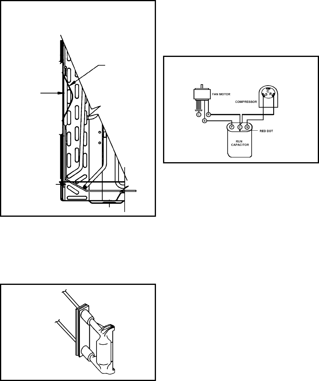
Compressors are single phase, 115 or 230/208 volt,
depending on the model unit. All compressor motors are
permanent split capacitor type using only a running capacitor
across the start and run terminal.
All compressors are internally spring mounted and externally
mounted on rubber isolators.
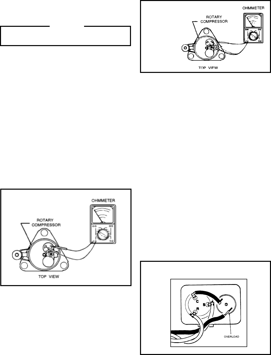
WINDING TEST
Remove compressor terminal box cover and disconnect wires
from terminals. Using an ohmmeter, check continuity across
the following: (See Figure 1)
1. Terminal "C" and "S" - no continuity - open winding -
replace compressor.
2. Terminal "C" and "R" - no continuity - open winding -
replace compressor.
3. Terminal "R" and "S" - no continuity - open winding -
replace compressor.
GROUND TEST
Use an ohmmeter set on its highest scale. Touch one lead to
the compressor body (clean point of contact as a good con-
nection is a must) and the other probe in turn to each com-
pressor terminal (see Figure 2.) If a reading is obtained, the
compressor is grounded and must be replaced.
CHECKING COMPRESSOR EFFICIENCY
The reason for compressor inefficiency is normally due to broken
or damaged suction and/or discharge valves, reducing the ability
of the compressor to pump refrigerant gas.
This condition can be checked as follows:
1. Install a piercing valve on the suction and discharge or
liquid process tube.
2. Attach gauges to the high and low sides of the system.
3. Start the system and run a “cooling or heating
performance test.”
If test shows:
A. Below normal high side pressure
B. Above normal low side pressure
C. Low temperature difference across coil
The compressor valves are faulty - replace the
compressor.
THERMAL OVERLOAD (External)
Some compressors are equipped with an external overload
which is located in the compressor terminal box adjacent to
the compressor body (See Figure 3.)
Figure 1
Figure 3- External Overload
Figure 2
Typical Ground Test
15
1. With no power to unit, remove the leads from the com-
pressor terminals.
2. Using an ohmmeter, test continuity between terminals
C-S and C-R. If no continuity, the compressor overload
is open and the compressor must be replaced.
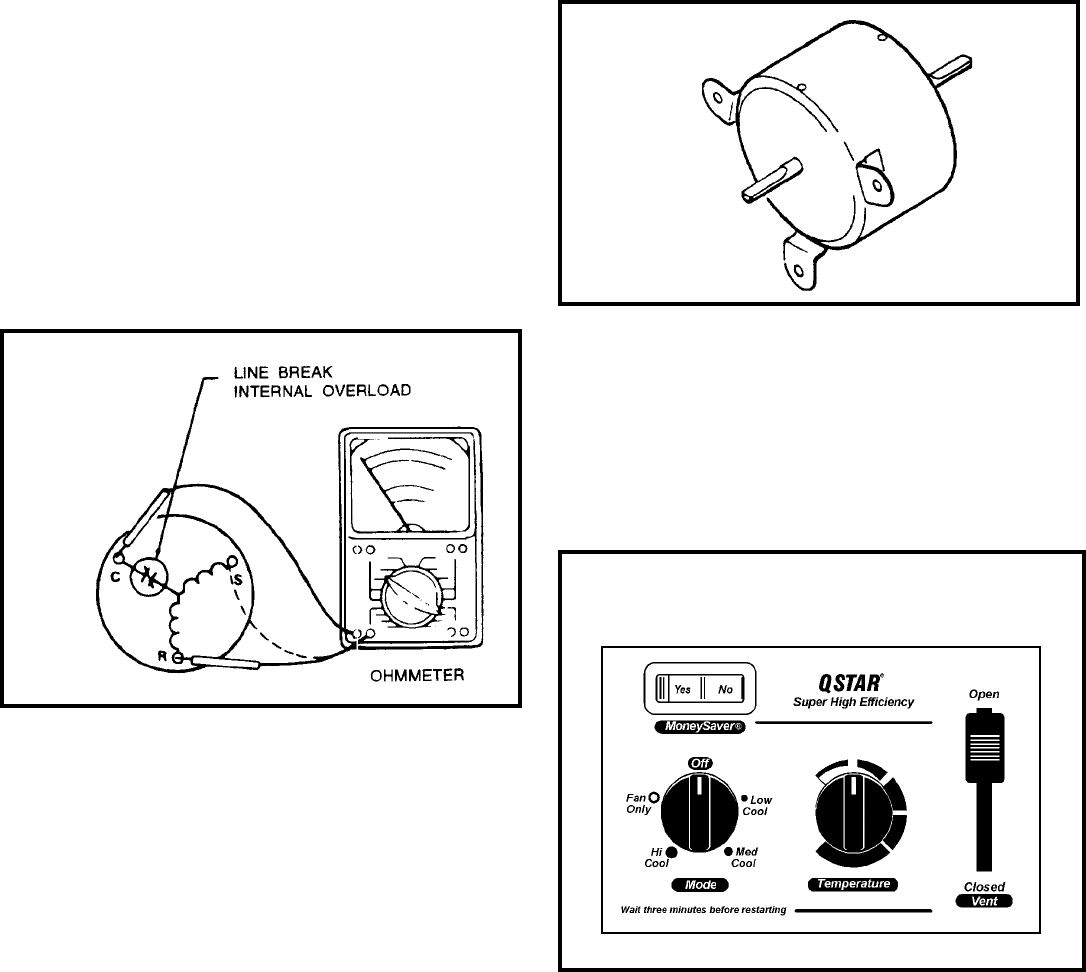
FAN MOTOR
A single phase permanent split capacitor motor is used to drive
the evaporator blower and condenser fan. A self-resetting over-
load is located inside the motor to protect against high tem-
perature and high amperage conditions. (See Figure 5)
CHECKING THE INTERNAL OVERLOAD
(See Figure 4)
Heat generated within the compressor shell is usually due to:
1. High amperage
2. Low refrigerant charge
3. Frequent recycling
4. Dirty condenser
TERMINAL OVERLOAD - TEST
(Compressor - External Type)
1. Remove overload.
2. Allow time for overload to reset before attempting to
test.
3. Apply ohmmeter probes to terminals on overload wires.
There should be continuity through the overload.
TERMINAL OVERLOAD (Internal)
Some model compressors are equipped with an internal
overload. The overload is embedded in the motor windings
to sense the winding temperature and/or current draw. The
overload is connected in series with the common motor
terminal.
Should the internal temperature and/or current draw become
excessive, the contacts in the overload will open, turning off
the compressor. The overload will automatically reset, but
may require several hours before the heat is dissipated.
Figure 4
Internal Overload
FAN MOTOR - TEST
1. Determine that capacitor is serviceable.
2. Disconnect fan motor wires from fan speed switch or
system switch.
3. Apply "live" test cord probes on black wire and common
terminal of capacitor. Motor should run at high speed.
4. Apply "live" test cord probes on red wire and common
terminal of capacitor. Motor should run at low speed.
5. Apply "live" test cord probes on each of the remaining
wires from the speed switch or system switch to test
intermediate speeds. If the control is in the
"MoneySaver" mode and the thermostat calls for
cooling, the fan will start - then stop after approximately
2 minutes; then the fan and compressor will start
together approximately 2 minutes later.
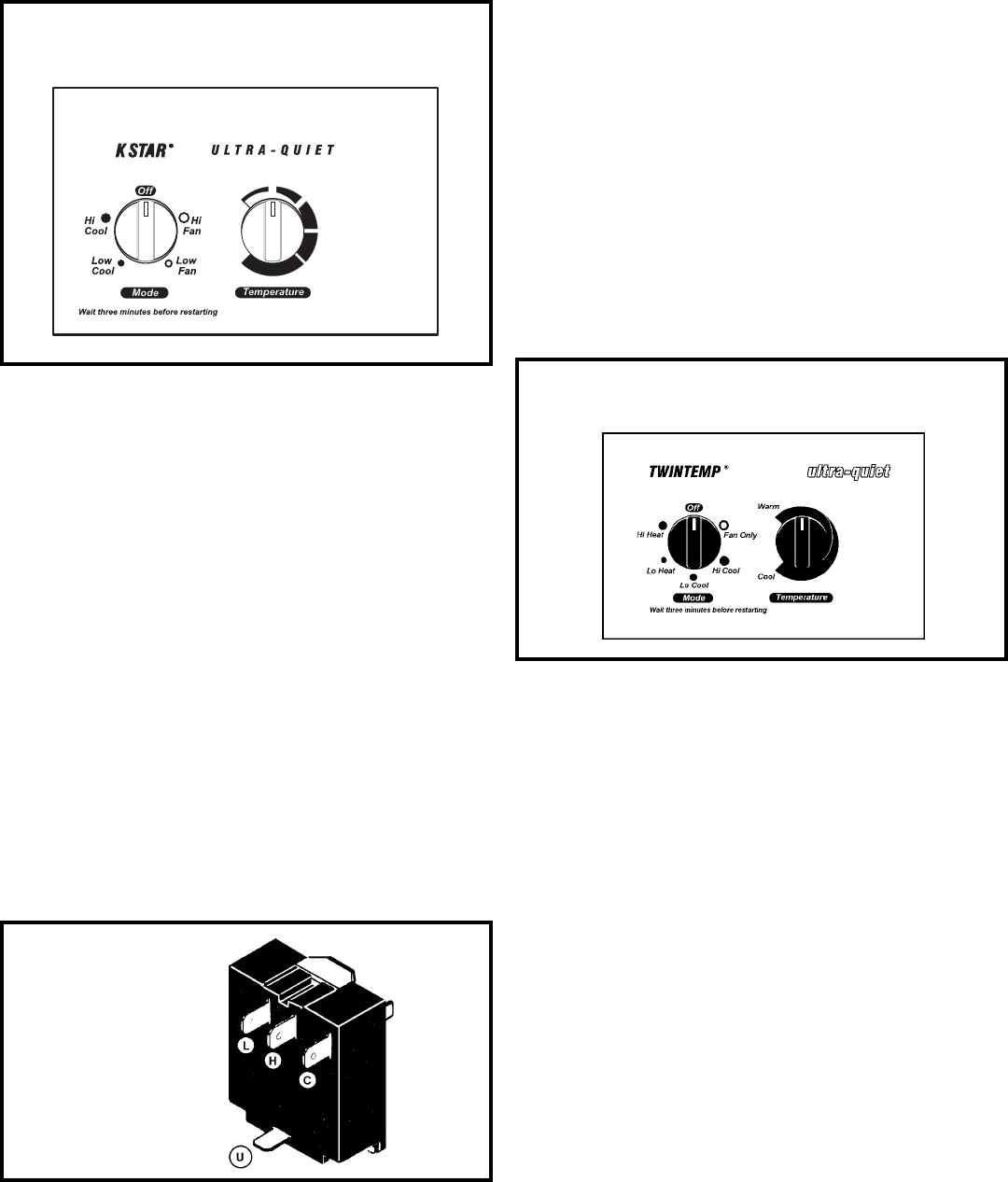
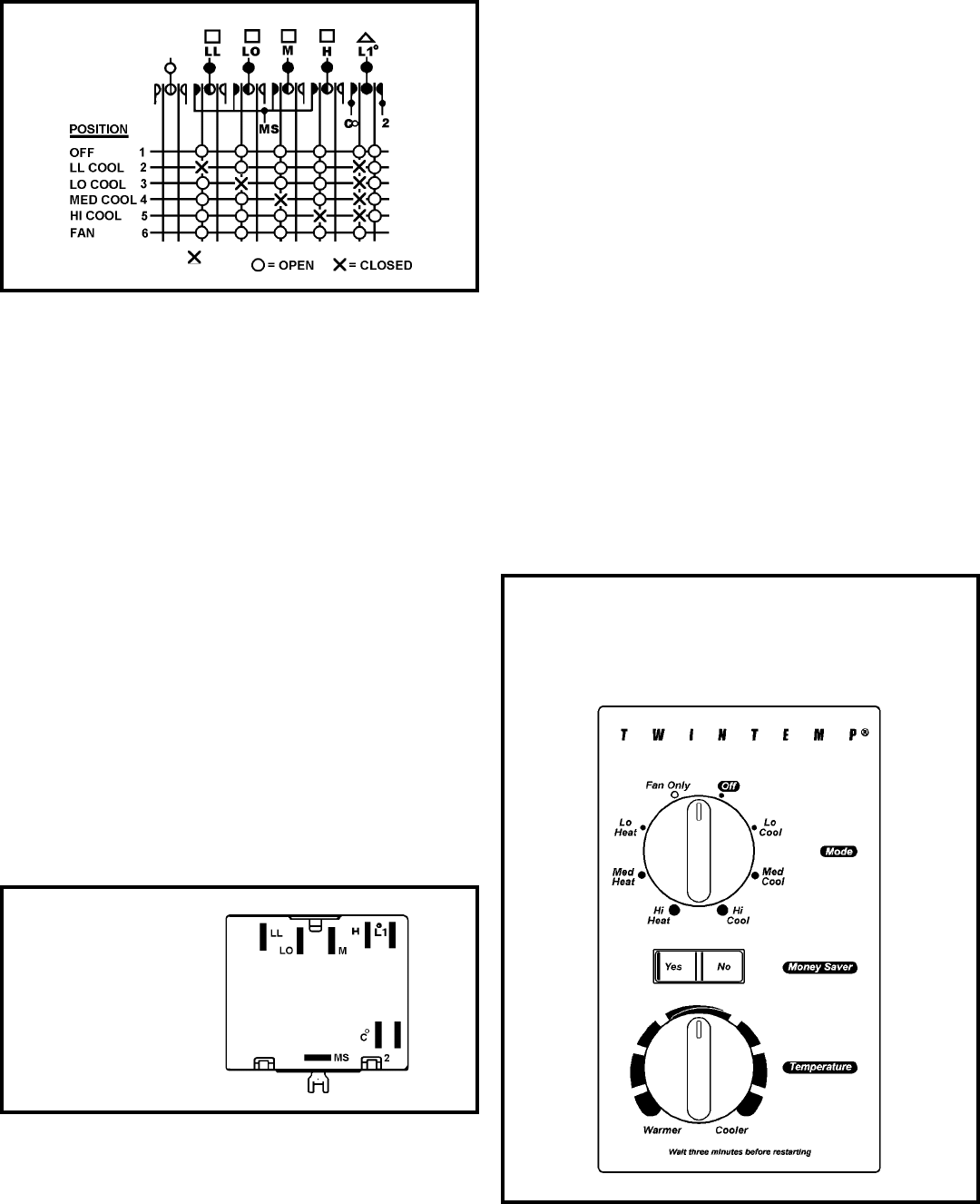
SYSTEM CONTROL PANEL- SQ Models (See Figure 6)
A five-position control switch is used to regulate the operation
of the fan motor and compressor. The compressor can be
operated with the fan operating at low, medium or high speed.
The fan motor can also be operated independently on medium
speed. See switch section as indicated on the decorative
control panel.
Figure 5
Fan Motor
Figure 6
System Control Panel (SQ Models Only)
16
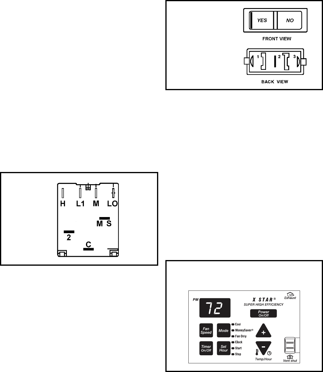
MONEYSAVER® SWITCH (Rocker Switch- See Figure 8)
This rocker switch can be depressed to either YES or NO. In
the YES position you will get the most economical operation.
Both the fan and the compressor will cycle on and off together,
maintaining the selected temperature at a more constant level
and reducing the humidity more efficiently. This control will
only operate when the unit is in a cooling mode. In the NO
position, the fan will run constantly as long as the unit is in the
cooling mode. Disconnect leads from switch. Depress switch
to function being tested.
1. When YES is depressed, there should be continuity
between terminals "1" and "2."
2. When NO is depressed, there should be continuity
between terminals "2" and "3."
Figure 7
System Switch
(SQ Only)
Rocker Switch
Figure 8
Figure 9
System Control Panel (XQ Models Only)
SYSTEM CONTROL PANEL (XQ MODELS ONLY)
(See Figure 9)
1. Power button turns the unit on and off.
2. Fan Speed button allows selection between three cool-
ing speeds and fan only.
3. The mode button allows the unit to switch between modes
(i.e., fan only, cooling, etc.).
4. Timer on/off button allows for programmed on and off
times (one hour increments).
5. The plus and minus buttons allows adjustments for room
air temperature.
6. Set hour button enables the unit’s timer on/off feature to
operate for times selected.
7. Exhaust/vent shut feature (if applicable) allows for room
air to continuously recalculate or if enabled, to exhaust
stale air.
Note: Please refer the troubleshooting guides on page if the
control is malfunctioning.
SYSTEM CONTROL SWITCH - TEST (See Figure 7)
Disconnect the leads from the control switch. There must be
continuity as follows:
1. "Off" Position - no continuity between terminals.
2. "Lo Cool" Position - between terminals "L1" and "C", "Lo"
and MS".
3. "Med Cool" Position - between terminals "L1" and "C", "M"
and "MS".
4. "Hi Cool" Position - between terminals L1" and "C", "H"
and "MS".
5. "Fan Only" Position - between terminals "L1" and "2".
RESISTOR
(Heat Anticipator) (SQ Only)
Failure of the resistor will cause prolonged "off" and "on" cycles
of the unit. When replacing a resistor, be sure and use the
exact replacement. Resistor rating 115 Volts 12500 ohm, 1.05
watts.
17
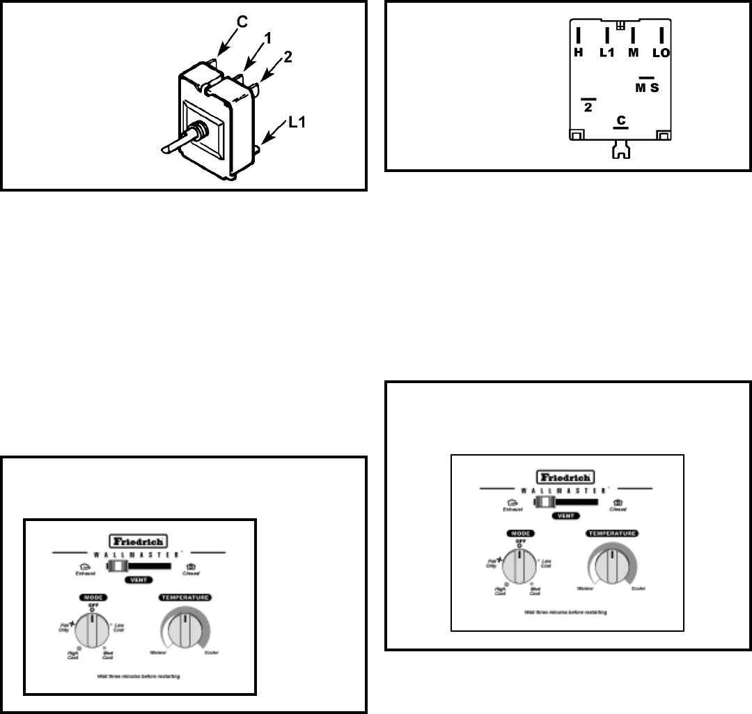
SYSTEM CONTROL PANEL
("KQ" Models Only- See Figure 10)
The KQ Model unit uses a five position control switch to regu-
late the operation of the unit. Function of each position (clock-
wise rotation) is as follows:
SYSTEM CONTROL SWITCH - TEST (See Figure 11) Turn knob
to phase of switch to be tested. There must be continuity as fol-
lows:
1. "Hi Fan" Position - between terminals "L1" and "H".
2. "Low Fan" Position - between terminals "L1" and "L".
3. "Low Cool" Position - between terminals "L1" and "L" and
"C".
4. "Hi Cool" Position - between terminals "L1" and "H" and "C".
Figure 11
System Control Switch
(KQ Models Only)
1. "Off" - Turns everything off.
2. "Hi Fan" - Maximum circulation of filtered room air (no
cooling.)
3. "Low Fan" - Fan runs slower for less circulation of fil-
tered room air.
4. "Low Cool" - Fan runs slowly for quiet operation when
maximum cooling is not needed.
5. "Hi Cool" - Highest fan speed for maximum cooling.
Figure 10
System Control Panel (KQ Models Only)
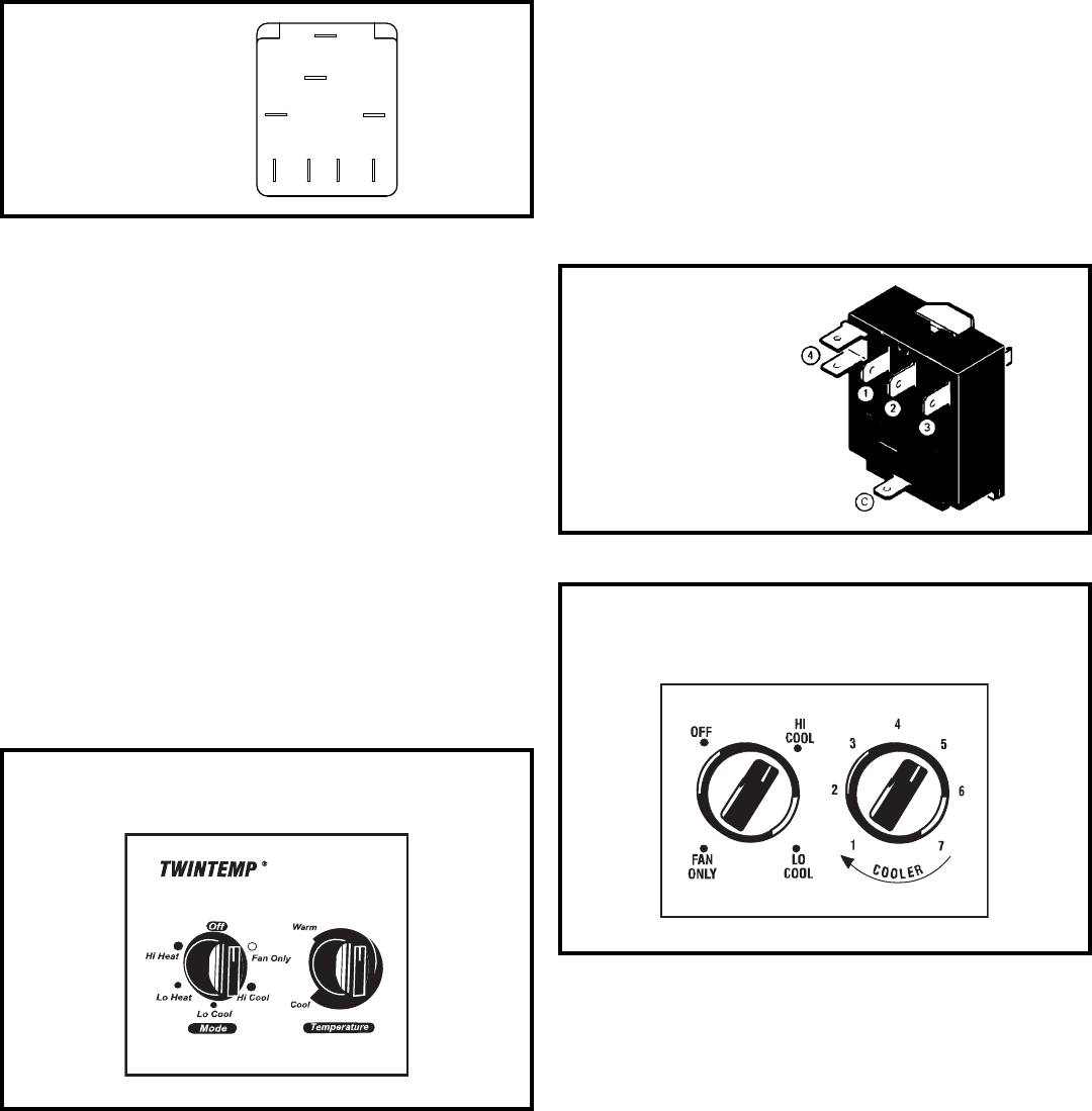
SYSTEM CONTROL PANEL
EQ Model Only (See Figure 12 )
The EQ Model unit uses a six-position control switch to regulate
the operation of the unit. Function of each position (clockwise
rotation) is as follows:
1. “Off” Turns everything off.
2. “Fan Only” To circulate filtered room air, but no cooling
or heating
3. “Hi Cool” Fan runs continuously, compressor goes on
and off to maintain the selected room temperature
4. “Lo Cool” fan runs continuously, compressor goes on and
off to maintain the selected room temperature.
5. “Lo Heat” Fan runs continuously, heating turns on and
off to maintain the selected room temperature.
6. Hi Heat” Fan runs continuously, heating turns on and off
to maintain the selected room temperature.
SYSTEM CONTROL SWITCH – TEST (See Figure 13)
Turn knob to phase of switch to be tested. There must be
continuity as follows:
1. “Fan Only” Position – between terminals “MS” and “H”
2. “Hi Cool” Position – between terminals “L1” and “C” and
“MS” and “H”
3. “Low Cool” Position – between terminals “L1” and “C”
and “MS” and “LO”
4. “Low Heat” Position – between terminals “L2” and “2”
and “MS” and “LO”
5. “Hi Heat” Position – between terminals “L2” and “2” and
“MS” and “H”
Figure 12
System Control Panel (EQ Models only)
18
1. "Hi Cool" Turns on the compressor and fan at high speed
2. "Lo Cool" Turns on the compressor and fan at low speed.
3. "Fan Only" Turns on the fan at high speed.
4. "Off" Turns everything off.
The switching arrangement of the control is as follows:
(See Figure 17)
1. "Off" All contacts open.
2. "Hi Fan
Contacts closed between terminals "L1" and
"1".
3. "Hi Cool" Contacts closed between terminals "L1" to "1"
and "L1" and "C".
4. "Lo-Cool" Contacts are closed between terminals "L1"
to "2" and "L1 to "C".
SYSTEM CONTROL PANEL ("YQ" Model Only)
(See Figure 14)
The YQ Model unit uses a six position control switch to regulate
the operation of the unit. Function of each position (Clockwise
rotation) is as follows:
1. "Off" - Turns everything off.
2. "Fan Only" - To circulate filtered room air, but no cooling
or heating.
3. "Hi Cool" - Fan runs continuously, compressor goes on
and off to maintain the selected room temperature.
4. "Lo Cool" - Fan runs continuously, compressor goes on
and off to maintain the selected room temperature.
5. "Lo Heat" - Fan Runs continuously, heating turns on and
off to maintain the selected room temperature.
6. "Hi Heat" - Fan Runs continuously, heating turns on and
off to maintain the selected room temperature.
SYSTEM CONTROL SWITCH - TEST (See Figure 15)
Turn knob to phase of switch to be tested. There must be
continuity as follows:
1. "Fan Only" Position - between terminals "C" and "1".
2. "Hi Cool" Position - between terminals "C" and "1", "C"
and "3".
3. "Lo Cool" Position - between terminals "C" and "2", and
"C" and "3".
Figure 14
System Control Panel (YQ Model Only)
Figure 15
System Control Switch
(YQ Model Only)
L1
MS
2
H
LO
C
L2
B1
Figure 13
System Control Switch
(EQ Models)
4. "Lo Heat" Position - between terminals "C" and "2", and
"C" and "4".
5. "Hi Heat" Position - between terminals "C" and "1", and
"C" and "4".
ROTARY (SYSTEM) SWITCH: "SC" Model (See Figure 16)
A rotary four position switch is used to turn on the unit and
select the operation desired. Switch selection is as follows:
Figure 16
System Control Panel (SC Model Only)
19
SYSTEM CONTROL SWITCH "WE" & "WY" Models
(See Figure 20)
An eight position switch is used to regulate the operation of
the fan motor, compressor and electric heater. The unit can
be operated in cooling or heating mode with the compressor
or electric heater on and the fan motor operating on low,
medium or high speed.
The fan motor can also be operated independently on medium
speed. See switch section as indicated on decorative control panel.
1. Disconnect leads from control switch.
2. Check continuity between all switch positions shown in
Figure 17.
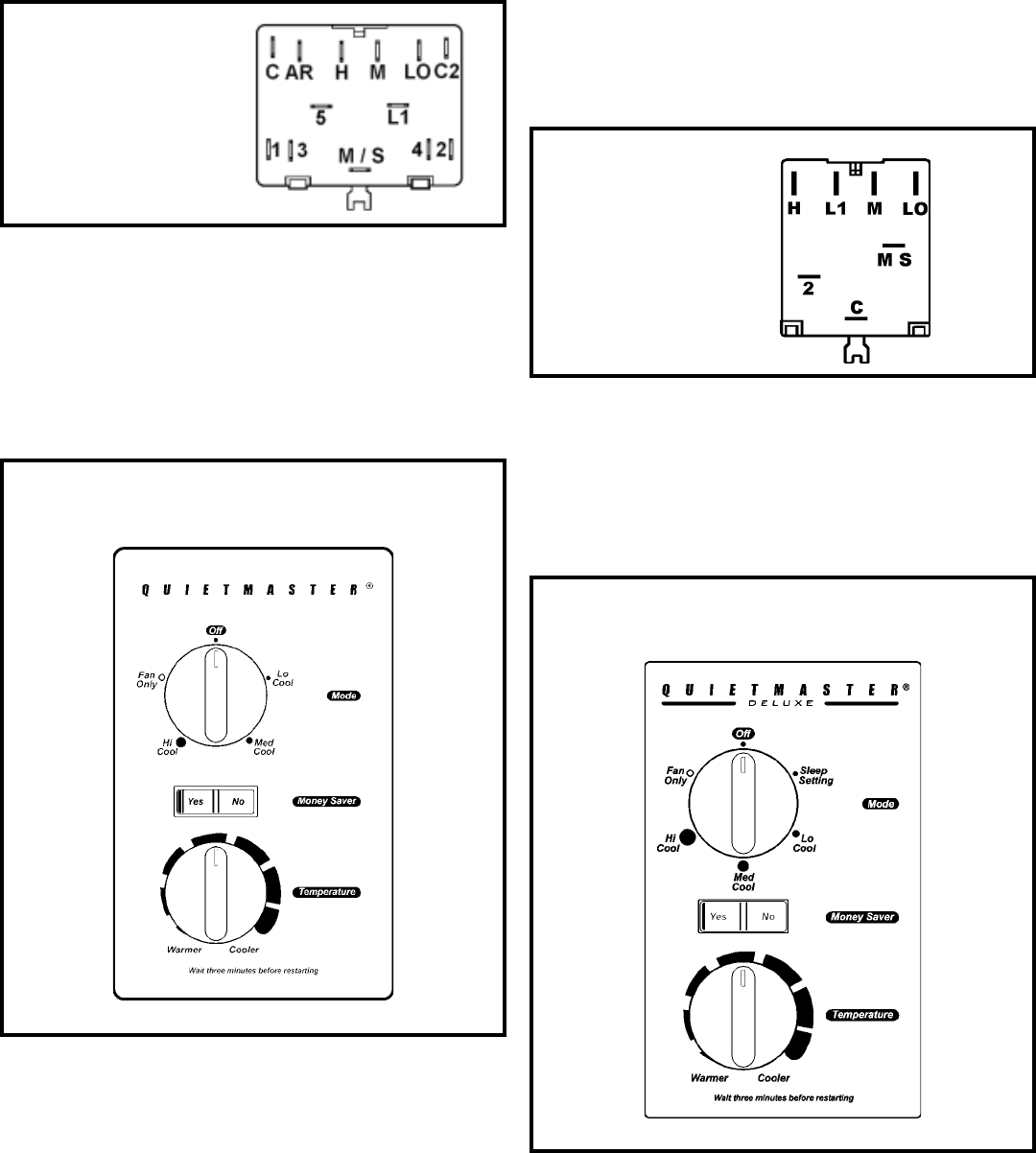
SYSTEM CONTROL PANEL
"WS" Models (See Figure 18)
A five position control switch is used to regulate the operation
of the fan motor and compressor. The compressor can be
operated with the fan operating at low, medium or high speed.
The fan motor can also be operated independently on medium
speed. See switch section as indicated on decorative control
panel
Figure 16
System Control Switch
(SC Model Only)
Figure 18
System Control Panel (WS Models)
SYSTEM CONTROL SWITCH - TEST
Disconnect leads from control switch (See Figure 19)
There must be continuity as follows:
1. "Off" Position - no continuity between terminals.
2. "Lo Cool" Position - between terminals "L1" and "C", "LO"
and "MS."
3. "Med Cool" Position - between terminals "L1" and "C", "M"
and "MS".
4. "Hi Cool" Position - between terminals "L1" and C", "H"
and "MS."
5. "Fan Only" Position - between terminals "L1" and "2."
Figure 19
System Control Switch
(WS Models)
Figure 20
System Control Panel
(WE & WY Models)
SYSTEM CONTROL SWITCH - TEST (See Figure 21)
Disconnect leads from control switch. Turn control to position
being tested. There must be continuity as follows:
1. "Off" Position-no continuity between terminals.
2. "Lo Cool" Position-between terminals "C" and "3", "C2"
and "2", "LO" and "M/S", "AR" and "5".
3. "Med Cool" Position-between terminals "C" and "3",
"C2" and "2", "M" and "M/S", "AR" and "5".
4. "Hi Cool" Position-between terminals "C" and "3", "C2"
and "2", "H" and "M/S", "AR" and "5".
5. "Hi Heat" Position-between terminals "C" and "1", "C2"
and "4", "H" and "M/S", "AR" and "5".
20
SYSTEM CONTROL PANEL (See Figure 24)
A six-position control switch is used to regulate the operation of
the fan motor and compressor. The compressor can be operated
with the fan operating at low, medium or high speed. The fan
motor can also be operated independently on medium speed.
See switch section as indicated on decorative control panel.
SYSTEM CONTROL SWITCH KS, SS, KM, SM, SL Models
(See Figure 22)
A five position control switch is used to regulate the operation of
the fan motor and compressor. The compressor can be operated
with the fan operating at low, medium or high speed. The fan
motor can also be operated independently on medium speed.
See switch section as indicated on decorative control panel.
SYSTEM CONTROL SWITCH - TEST (See Figure 23)
Disconnect leads from control switch. There must be continuity
as follows:
1. "Off" Position - no continuity between terminals.
2. "Lo Cool" Position - between terminals "L1" and "C," "LO"
and "MS."
3. "Med Cool" Position - between terminals "L1" and "C,"
"M" and "MS."
4. "Hi Cool" Position - between terminals "L1" and "C,"
"H"and "MS."
5. "Fan Only" Position - between terminals "L1" and "2."
Figure 23
System Control Switch
Figure 24
System Control Panel - Deluxe Series (RS & RM)
Figure 21
System Control Switch
Heat Pump / Electric Heat
(WE & WY Models)
6. "Med Heat" Position-between terminals "C" and "1",
"C2" and "4", "M" and "M/S", "AR" and "5".
7. "Lo Cool" Position-between terminals "C" and "1", "C2"
and "4", "LO" and "M/S", "AR" and "5".
8. "Fan Only" Position-between terminals "L1" and "M".
Figure 22
System Control Panel (KS, SS, KM, SM, SL)
21
SYSTEM CONTROL SWITCH (See Figure 26)
(Heat Pump & Electric Heat Models)
An eight position control switch is used to regulate the
operation of the fan motor and compressor. The compressor
can be operated with the fan operating at low, medium or high
speed in the cooling or heating mode. The fan motor can also
be operated independently on medium speed. See switch
section as indicated on decorative control panel.
1. "Off" Position - everything is off.
2. "Lo Cool" Position - fan operates on low speed,
compressor is on.
3. "Med Cool" Position - fan operates on medium speed,
compressor is on.
4. "Hi Cool" Position - fan operates on high speed,
compressor is on.
5. "Hi Heat" Position - fan operates on high speed,
compressor or electric heater is on.
6. "Med Heat" Position - fan operates on medium speed,
compressor or electric heater is on.
SYSTEM CONTROL SWITCH - TEST
Disconnect leads from control switch (See Figure 25)
There must be continuity as follows:
Figure 25
Figure 26
System Control Switch
SYSTEM CONTROL SWITCH
(Heat Pump & Electric Heat Models) (See Figure 27)
An eight position control switch is used to regulate the
operation of the fan motor and compressor. The compressor
can be operated with the fan operating at low, medium or high
speed in the cooling or heating mode. The fan motor can also
be operated independently on medium speed. See switch
section as indicated on decorative control panel.
1. "Off" Position - everything is off.
2. "Lo Cool" Position - fan operates on low speed,
compressor is on.
3. "Med Cool" Position - fan operates on medium speed,
compressor is on.
4. "Hi Cool" Position - fan operates on high speed,
compressor is on.
5. "Hi Heat" Position - fan operates on high speed,
compressor or electric heater is on.
6. "Med Heat" Position - fan operates on medium speed,
compressor or electric heater is on.
7. "Lo Heat" Position - fan operates on low speed,
compressor or electric heater is on.
8. "Fan Only" Position - operates on medium speed.
NOTE: Heat pump models with electric heat - in the heat
position, heating element only will be energized when outdoor
temperature is below the operating range of the heat pump.
Figure 27
System Control Panel
Heat Pump & Electric Heat Models
(YS, ES, YM, EM, YL & EL)
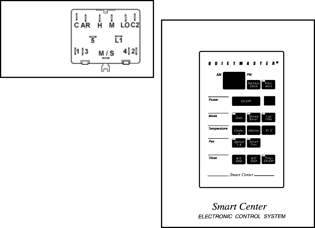
22
Smart Center Electronic Control Center
(See Figure 29)
FILTER ALERT light will come on after 250 hours of use. Touch
FILTER ALERT to reset.
TO SET MODE OF OPERATION
When unit is first turned on, it will be in the COOL mode (light
on), with constant fan.
Touch MONEYSAVER (light on) to activate the MoneySaver
feature. (MoneySaver is a feature that cycles the fan with the
compressor so that the fan does not run all the time. This
saves energy and improves dehumidification.) If customer
prefers a constant fan for more air movement, touch
MONEYSAVER again and unit will return to constant fan.
Touch FAN ONLY (light on) and only the fan will run. This
feature may be used in conjunction with the FRESH AIR/
EXHAUST lever to bring outside air into a room, or to exhaust
stale air.
SYSTEM CONTROL SWITCH - TEST (See Figure 28)
Disconnect leads from control switch. Turn control to position
being tested. There must be continuity as follows:
1. "Off" Position - no continuity between terminals.
2. "Lo Cool" Position - between terminals "C" and "3", "C2"
and "2", "LO" and "M/S", "AR" and "5".
3. "Med Cool" Position - between terminals "C" and "3", "C2"
and "2", "M" and "M/S", "AR" and "5".
4. "Hi Cool" Position - between terminals "C" and "3", "C2"
and "2", "H" and "M/S", "AR" and "5".
5. "Hi Heat" Position - between terminals "C" and "1", "C2"
and "4", "H" and "M/S", "AR" and "5".
6. "Med Heat" Position - between terminals "C" and "1", "C2"
and "4", "M" and "M/S", "AR" and "5".
7. "Lo Cool" Position - between terminals "C" and "1", "C2"
and "4", "LO" and "M/S", "AR" and "5".
8. "Fan Only" Position - between terminals "L1" and "M".
Figure 28
System Control Switch
(Heat Pump / Electric
Heat Models
TO ADJUST TEMPERATURE
COOLER - Touch COOLER to see setting, touch again to
change.
WARMER - Touch WARMER to see setting, touch again to
change.
Touch °F/°C to show desired temperature in Fahrenheit or
Celsius.
TO ADJUST FAN SPEED
Touch SPEED to see current setting. Touch again to change
speed. F1 is lowest setting (sleep setting), F2 is LOW, F3 is
MED, and F4 is HIGH.
TO ACTIVATE SMART FAN
Touch SMART FAN (light on). Smart Fan will adjust the fan
speed automatically to maintain the desired comfort level. For
example, if the outside doors in the home are open for an
extended period of time, or more people enter a room, Smart
Fan may adjust to a higher fan speed to compensate for the
increased heat load. This keeps from having to adjust the fan
speed on your own, or from having to change the desired
temperature you have selected. Smart Fan will also run to
test temperature if the off cycle is long.
Figure 29
Electronic Control

23
TO SET HOUR CLOCK
Touch SET HOUR CLOCK to see setting. To change, touch
and hold until hour closest to the actual time appears in the
display. MAKE SURE A.M. AND P.M. ARE SET PROPERLY.
(Minutes will NOT show on display.)
TO SET THE TIMER
NOTE: SET HOUR CLOCK before attempting to set timer
functions.
The TIMER ON/OFF times can be set a minimum of one
hour apart and a maximum of twenty-three hours apart.
STOP TIME - Touch A/C STOP and hold until the hour the
unit needs to shut off appears in the display A.M. or P.M.)
START TIME - Touch A/C START and hold until the hour the
unit needs to come on appears in the display (A.M. or P.M.)
Touch TIMER ON (light on) to activate the timer function. Touch
TIMER OFF (light off) to cancel the timer function desired.
Once the on and off times have been selected, they will remain
in memory, and cycle daily until changed, or until the unit is
subject to a power interruption.
TESTING THE ELECTRONIC CONTROL
2003 XQ BOARDS & QME BOARDS
Checking Room Temperature:
1. Check the room temperature at the electronic control pad
by pressing the "FAN SPEED" button and the temperature
"UP" button at the same time on XQ models.
2. Check the room temperature at the electronic control pad
by pressing at the same time the "FAN SPEED" button
and the "WARMER" button on QME models.
The indoor temperature will display for 10 seconds. Indoor
temperature can be viewed in all modes, including the TEST
mode. The display can be changed back to SET
temperature by pressing any key, except the ON/OFF
button, or after 10 seconds has elapsed.
Activating Test Mode: Activate test mode by pressing at
the same time the "MODE" button and the temperature
"DOWN" button on XQ models. LEDs for Hour, Start, and
Stop will blink 1 bps while Test Mode is active.
Activate test mode by pressing at the same time the
"MONEY SAVER" button and the "FILTER ALERT" button
on QME models. LED for the Filter Alert will blink 1 bps
while Test Mode is active.
Test Mode has duration of 90 minutes. Test Mode can be
activated under any conditions, including Off. Test Mode is
cancelled by pressing the On/Off button, unplugging the
unit, or when the 90 minutes is timed out. All settings revert
to the factory default settings of Cool, 75 degrees F, Timer
and Set Hour features are nonfunctional.
Test Mode overrides the three-minute lockout, all delays
for compressor and fan motor start / speed change, and no
delay when switching modes.
Test Mode default settings are ON, Money Saver, 60 degrees F,
and High fan speed
.
Activating Error Code Mode: (Submode of Test Mode) Unit
has to be in Test Mode to enter Error Code Mode
1. Activate Error Code Mode by pressing the "TIMER ON/
OFF" button on XQ models. LED for the "TIMER ON/OFF"
will flash 1 bps while Error Code Mode is active. Pressing
the "TEMP/HR + " button will display 00. Consecutive
presses will scroll through all error codes logged. Press
the "TEMP/HR - " button to see the reverse order of all
error codes logged. When the end of logged error codes is
reached the temperature set point will appear.
Activate Error Code Mode by pressing at the same time
the "A/C START" button and the "ON/OFF" button on QME
models. LED for the "TIMER ON/OFF" will flash 1 bps while
Error Code Mode is active. Pressing the "WARMER" button
will display 00. Consecutive presses will scroll through all
error codes logged. Press the "COOLER" button to see
the reverse order of all error codes logged. When the end
of logged error codes is reached the temperature set point
will appear.
IMPORTANT: Error Codes are cleared from the log
by exiting from Error Code Mode. To exit on XQ mod-
els, press Timer On/Off button. To exit QME models,
press A/C Start and On/Off buttons. Or unplug unit to
exit Error Code Mode. Plug unit in after 5 seconds to
resume normal operation of unit.
TESTING THE ELECTRONIC CONTROL
ERROR CODE LISTINGS
E1 SHORT CYCLE SITUATION: Defined as (compressor
powered on before the three minute time delay ten times in
one hour. Investigate and correct short cycling problem.
E2 KEYBOARD STUCK ERROR: If key button(s) are pressed
continuously for twenty seconds or more. If MODE key is stuck,
unit will default to cool. Exit Error Code Mode to see if error
"E2" is no longer displayed and unit is functioning. Replace
board if "E2" still displays after exiting Error Code Mode.
E3 FROST PROBE OPEN: Normal operation is allowed. Ohm
frost probe. Replace probe if ohm value not read. If ohm value
present replace board.
E4 FROST PROBE SHORT: Normal operation allowed.
Replace probe.
E5 INDOOR PROBE OPEN: Control assumes indoor ambient
temperature is 90 degree F and unit will operate. Ohm indoor
probe. Replace probe if ohm value not read.
E6 INDOOR PROBE SHORT: Control assumes ambient
temperature is 90 degree F and unit will operate. Replace
probe.
NOTE: All Error Code displays for Frost & Indoor Probe will
allow unit to operate. Unit may or will ice up if faulty components
not replaced.
FROST PROBE SENSOR: disables compressor at 35
degrees F.
INDOOR PROBE SENSOR: Control range is 60 degrees F
to 90 degrees F +/- 2 degrees F.
Indoor temperature will be displayed by pressing:
24
THERMOSTAT - Models ES, YS, EM, YM, EL, YL
(See Figure 32)
A cross ambient thermostat is used on all heat pump and
electric heat units. In addition to cycling the unit in a heating
or cooling operation, the thermostat will terminate the cooling
cycle in the event ice forms on the evaporator coil, in this
case the thermostat functions as a de-ice control. A resistor
(anticipator) is positioned within a plastic block to supply a
small amount of heat to the bulb area to prevent long "off
cycles" in the "Cool-Fan Auto" (MoneySaver) position (see
Figure 8.) A current feedback through the fan motor windings
during "off cycle" completes the circuit to the resistor.
TEST:
1. Remove leads from thermostat.
2. Turn thermostat knob clockwise to its coldest position.
3. Test for continuity between the two terminals. Contacts
should be closed.
4. Turn thermostat knob counterclockwise to its warmest
position.
5. Test for continuity - contacts should be open.
NOTE: The thermostat must be within the temperature
range listed to open and close.
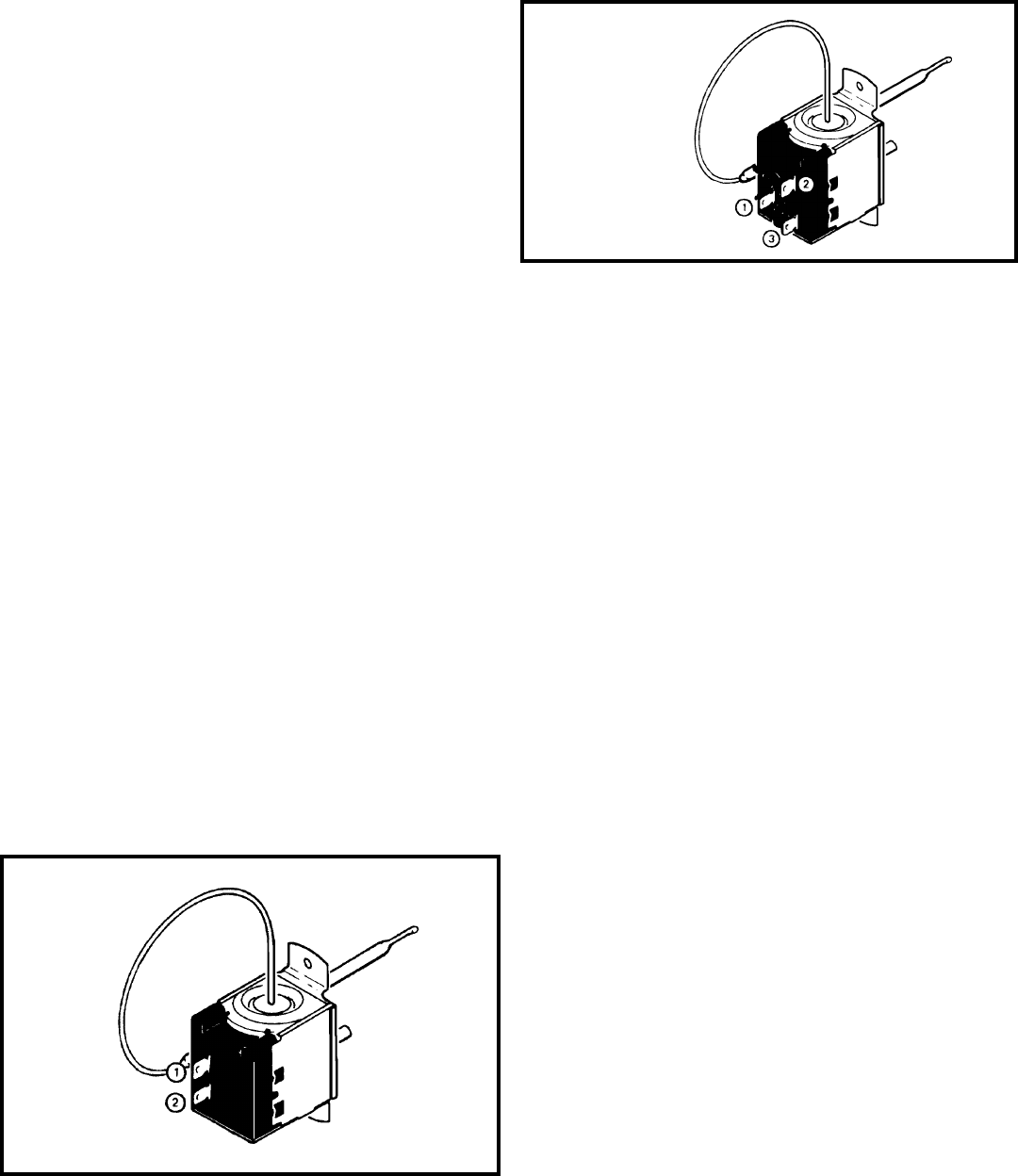
THERMOSTAT ("YQ" Model Only) (See Figure 31)
This thermostat is single pole-double throw, cross ambient
with a range of 60° to 92°F and a differential of ±2°F. Terminal
"2" is common.
THERMOSTAT ("SQ & KQ" Models) - See Figure 30.
Thermostat is used to cycle the compressor on and off at the
comfort level desired. The thermostat has a range from 60°
±2°F to 90° ±4°F, with a differential of 5°F. Turning the knob
clockwise lowers the indoor room temperature setting, while
turning the knob counter clockwise raises the indoor
temperature.
TEST:
Remove wires, turn thermostat to its coldest position. Check
for continuity between the two terminals. Turn thermostat to
warmest position, check continuity to see if contacts open.
NOTE: Temperature must be in range listed to check
thermostat.
To maintain the comfort level desired, a cross ambient type
thermostat is used. The thermostat has a range from 65° ±2°F
to 87° ±3°F. The thermostat bulb is positioned in front of the
evaporator coil to sense the return air temperature. Thermo-
stat malfunction or erratic operation is covered in the trouble-
shooting section of this manual.
TEST:
1. Remove leads from thermostat.
2. Turn thermostat knob clockwise to its coldest position.
3. Test for continuity between the two terminals. Contacts
should be closed.
4. Turn thermostat knob counterclockwise to its warmest
position.
5. Test for continuity - contacts should be open.
NOTE: The thermostat must be within the temperature range
listed to open and close.
Figure 30
Thermostat
(QME Units) The Fan Speed button and the Warmer button.
( XQ Units) The Fan Speed button and the Temp Up button.
The indoor temperature will be displayed for 10 seconds. The
display will change back to the Set Point temperature by
pressing any key button except for the On/Off button. The
indoor temperature can be viewed in all modes, including test
mode.
Filter Alert: The Filter Alert indicator turns on after the fan
motor has been operating for 250 hours. The Filter Alert
indicator is reset by pressing the Filter Alert button one time
only,. Power failures will not reset the 250 hour timer. All time
elapsed is stored in memory and resumes counting after power
is restored.
Keep Alive: The electronic control has a memory to retain all
functions and status as set up by the user in the event of a
power failure. Once power is restored to the unit there is a
two second delay before the fan comes on and approximately
three minutes delay before the compressor is activated,
providing that the mode was set for cooling and the set point
temperature has not been met in the room.
Figure 31
Thermostat
(YQ Models Only)
25
DEFROST THERMOSTAT (Heat Pump Models Only)
(See Figure 35)
This thermostat is single pole - double throw with contacts
between terminals "2" and "3" closing on temperature rise
and contacts between terminals "2" and "1" closing on
temperature fall. When the contacts between terminals "2"
and "1" make, power is supplied to the heater element.
This control is dual purpose control that acts as an outdoor
thermostat and defrost control.
When the sensing bulb, attached to the condenser coil, senses
enough icing on the outdoor coil, it will interrupt power to the
compressor and supply power to the heating element until
the coil temperature reaches above 43°, then the heater will
shut off and the unit will resume operating in the reverse cycle
mode.
When the outdoor coil temperature drops below 20°, the unit
will operate in electric heat mode continuously until the outdoor
coil temperature rises above 43°.
The fan motor will not turn off when defrost occurs, and the 4-
way valve will not reverse.
Figure 32
Thermostat
In the heating cycle, the heat anticipator is energized to supply
a small amount of heat during the "on" cycle. This will open
the contacts in the thermostat prematurely to maintain a closer
differential between the "cut in" and "cut out" temperature.
The heat anticipator is energized in the heating mode
regardless of whether fan is placed in the automatic
(MoneySaver) or constant run position.
RANGE: Cooling Model Thermostat
60°F (±2°) to 92°F (±4°),
TEST:
Cooling/Heating Models: Remove wires from thermostat
and check continuity between terminal "2" (common) and "3"
for cooling. Check between terminals "2" (common) and "1"
for heating. Also check that contacts in thermostat open after
placing in either position. NOTE: Temperature must be within
range listed to check thermostat. Refer to the troubleshooting
section in this manual for additional information on thermostat
testing.
THERMOSTAT ADJUSTMENT
No attempt should be made to adjust thermostat. Due to the
sensitivity of the internal mechanism and the sophisticated
equipment required to check the calibration, it is suggested
that the thermostat be replaced rather than calibrated.
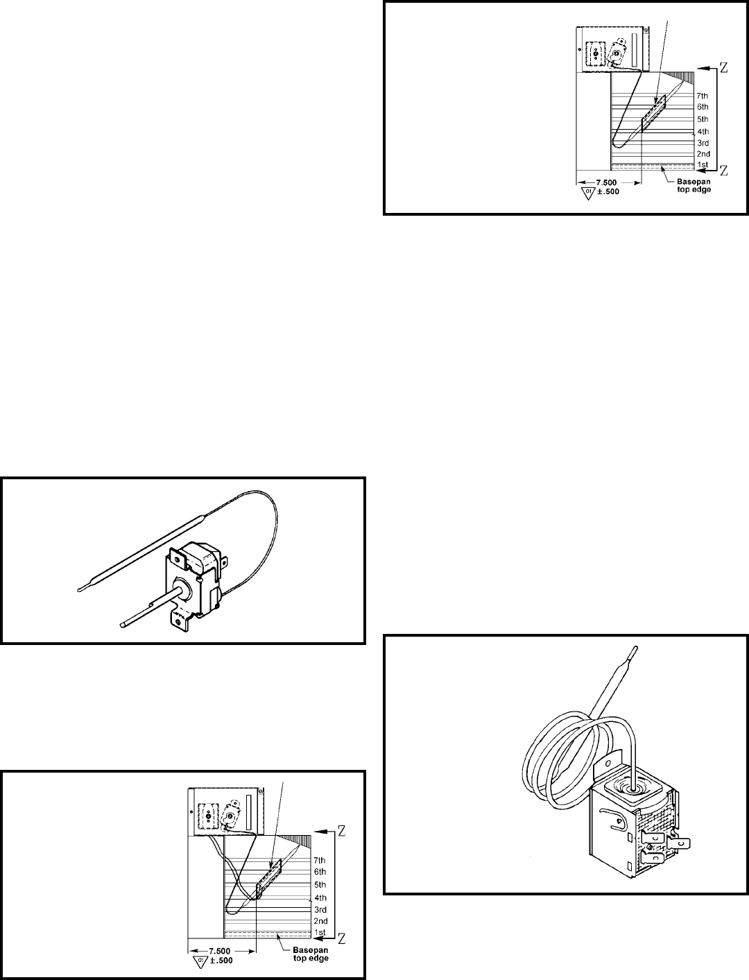
Thermostat bulb must be straight to insure proper
performance.
THERMOSTAT BULB LOCATION
The position of the bulb is important in order for the thermostat
to function properly. The bulb of the thermostat should be
located approximately 45° to a maximum of 60° from
horizontal. Also, do not allow the thermostat bulb to touch the
evaporator coil. (See Figures 33 and 34)
Thermostat sensor holder
020 to be positioned between
the 4th and 5th and 6th and
7th rows of tubes from the
bottom of the coil at
dimension shown
Figure 34
Thermostat Bulb Location
(KQ, YQ & SC Models Only)
Thermostat sensor holder
020 and anticipator
(4712D-140) to be
positioned between the
4th and 5th and 6th and
7th rows of tubes from
the bottom of the coil at
dimension shown
Figure 33
Thermostat Bulb Location
(SQ Models Only)
Figure 35
Defrost Thermostat
(Heat Pump Models)
26
CAPACITOR, RUN (See Figure 38)
A run capacitor is wired across the auxiliary and main winding
of a single phase permanent split capacitor motor such as the
compressor and fan motor. A single capacitor can be used for
each motor or a dual rated capacitor can be used for both.
The capacitor's primary function is to reduce the line current
while greatly improving the torque characteristics of a motor.
The capacitor also reduces the line current to the motor by
improving the power factor of the load. The line side of the
capacitor is marked with a red dot and is wired to the line side
of the circuit.
DEFROST BULB LOCATION (Heat Pump Models Only)
(See Figure 36)
The defrost control bulb must be mounted securely and in the
correct location to operate properly.
RESISTOR: Heat Anticipator (See Figure 37)
Failure of the resistor will cause prolonged "off" and "on" cycles
of the unit. When replacing a resistor, be sure and use the
exact replacement. Resistor ratings are as follows:
115 Volt - 5,000 ohms 3 watt
230 Volt - 20,000 ohms 3 watt
Figure 37
Resistor
Slide the bulb
end of the
thermostat
defrost under
the retainer as
shown
Retainer
Figure 36
Defrost Thermostat Bulb
Location (All Heat Pump Models)
CAPACITOR - TEST
1. Remove capacitor from unit.
2. Check for visual damage such as bulges, cracks, or leaks.
3. For dual rated, apply an ohmmeter lead to common
(C) terminal and the other probe to the compressor
(HERM) terminal. A satisfactory capacitor will cause a
deflection on the pointer, then gradually move back to
infinity.
4. Reverse the leads of the probe and momentarily touch
the capacitor terminals. The deflection of the pointer
should be two times that of the first check if the capacitor
is good.
5. Repeat steps 3 and 4 to check fan motor capacitor.
NOTE: A shorted capacitor will indicate a low resistance and
the pointer will move to the "0" end of the scale and remain
there as long as the probes are connected.
An open capacitor will show no movement of the pointer when
placed across the terminals of the capacitor.
Figure 38
Dual Rated Run Capacitor Hook-up
27
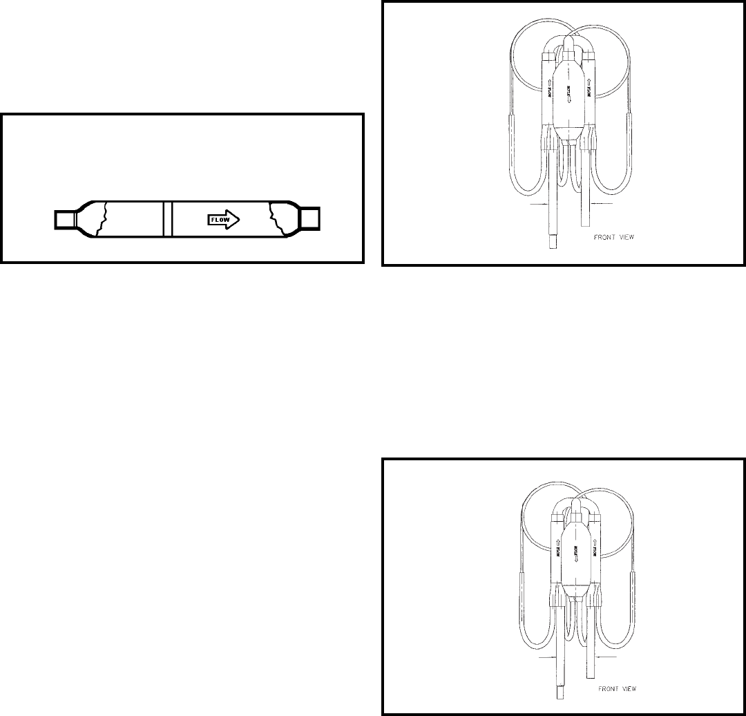
CHECK VALVE (See Figure 39)
A unique two-way check valve is used on the reverse cycle
heat pumps. It is pressure operated and used to direct the
flow of refrigerant through a single filter drier and to the proper
capillary tube during either the heating or cooling cycle
NOTE: The slide (check) inside the valve is made of teflon.
Should it become necessary to replace the check valve, place a
wet cloth around the valve to prevent overheating during the
brazing operation.
CHECK VALVE OPERATION
In the cooling mode of operation, high pressure liquid enters the
check valve forcing the slide to close the opposite port (liquid
line) to the indoor coil. Refer to refrigerant flow chart. This directs
the refrigerant through the filter drier and cooling capillary tube
to the indoor coil.
In the heating mode of operation, high pressure refrigerant enters
the check valve from the opposite direction, closing the port (liquid
line) to the outdoor coil. The flow path of the refrigerant is then
through the filter drier and heating capillary to the outdoor coil.
Failure of the slide in the check valve to seat properly in either
mode of operation will cause flooding of the cooling coil. This is
due to the refrigerant bypassing the heating or cooling capillary
tube and entering the liquid line.
COOLING MODE (See Figure 40)
In the cooling mode of operation, liquid refrigerant from con-
denser (liquid line) enters the cooling check valve forcing the
heating check valve shut. The liquid refrigerant is directed
into the liquid dryer after which the refrigerant is metered
through cooling capillary tubes to evaporator. (Note: liquid
refrigerant will also be directed through the heating capillary
tubes in a continuous loop during the cooling mode).
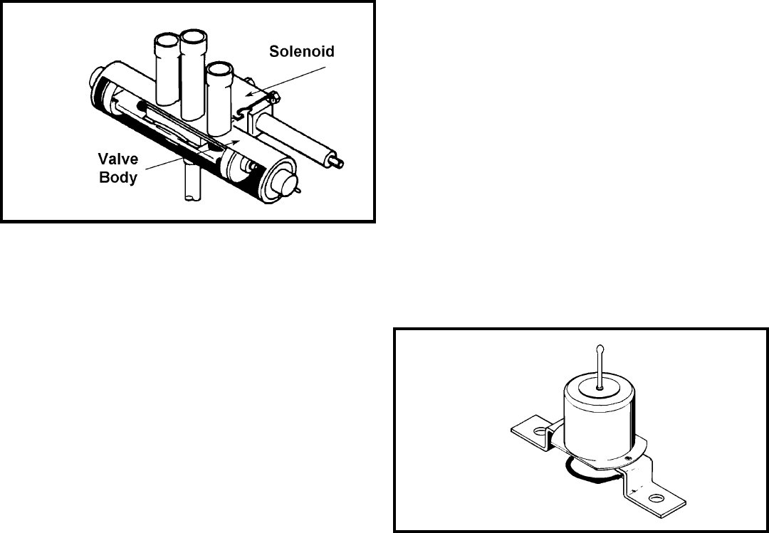
HEAT PUMPS: REVERSING VALVE (See Figure 42)
A reversing valve is used to change the refrigerant flow within
the system to permit heating or cooling.
The reversing valve consists of a main valve body which houses
the slide and piston, plus a pilot valve which is activated by a
solenoid.
(TO INDOOR COIL) (TO OUTDOOR COIL)
Figure 41
HEATING MODE (see Figure 41)
In the heating mode of operation, liquid refrigerant from the
indoor coil enters the heating check valve forcing the cooling
check valve shut. The liquid refrigerant is directed into the
liquid dryer after which the refrigerant is metered through the
heating capillary tubes to outdoor coils. (Note: liquid refriger-
ant will also be directed through the cooling capillary tubes in
a continuous loop during the heating mode).
(TO INDOOR COIL) (TO OUTDOOR COIL)
Figure 40
Figure 39
One-way Check Valve
(Heat Pump Models)
28
TESTING REVERSING VALVE
Occasionally, the reversing valve may stick in the heating or
cooling position or in the mid-position.
When stuck in the mid-position, part of the discharge gas from
the compressor is directed back to the suction side, resulting
in excessively high suction pressure.
Check the operation of the valve by starting the system and
switching the operation from "Cooling" to "Heating" and then
back to "Cooling". Do not hammer on valve.
If valve fails to change its position, test the voltage to the valve
coil while the system is in the heating cycle. If voltage to coil is
satisfactory, replace reversing valve.
Should the valve fail to shift from cooling to heating, block the
air flow through the outdoor coil and allow the discharge
pressure to build in the system. Then switch the system from
heating to cooling.
If the valve is stuck in the heating position, block the air flow
through the indoor coil and allow discharge pressure to build
in the system. Then switch the system from heating to cooling.
Should the valve fail to shift in either position after increasing
the discharge pressure, replace the valve.
NOTE: When brazing a reversing valve into the system, it is
of extreme importance that the temperature of the valve does
not exceed 250° F at any time.
Wrap the reversing valve with a large rag saturated with water.
"Re-wet" the rag and thoroughly cool the valve after each
brazing operation of the four joints involved.
The wet rag around the reversing valve will eliminate
conduction of heat to the valve body when brazing the line
connection.
SOLENOID COIL (Heat Pump Models Only)
(See Figure 42)
The solenoid coil is an electromagnetic type coil mounted on
the reversing valve and is energized during the operation of
the compressor in the heating cycle.
Should the reversing valve fail to shift during the heating cycle,
test the solenoid coil.
TO TEST:
1. Disconnect power to unit.
2. Disconnect coil leads.
3. Attach probes of an ohmmeter to each coil lead and check
for continuity.
NOTE: Do not start unit with solenoid coil removed from
valve, or do not remove coil after unit is in operation.
This will cause the coil to burn out.
There are three tubes connected to one side of the main
valve body and one tube on the opposite side. The single
tube is connected to the compressor discharge line. The
center tube on the opposite side is the common suction line
to the compressor. The outside tubes are connected to the
indoor and outdoor coils.
The pivot valve is responsible for directing the refrigerant
flow to the indoor or outdoor coil. There are three small tubes
connected to the pilot valve body. The center pilot tube is the
common pilot tube and is connected to the center suction
line. The outside tubes are connected to each end of the
main valve body. The pilot valve consists of a needle valve
and spring.
When the solenoid is de-energized, the spring tension closes
one pilot port while the other remains open. When the
solenoid is energized, the opposite end is closed. The piston
in the main valve is pressure operated and will always travel
in the direction of the open pilot tube port which provides a
path to the center tube. Pressure which will increase in the
opposite side of the valve will escape through a bleed port
located in each piston. When de-energized, the valve will be
in the cooling position.
Figure 42
Reversing Valve
Figure 43
Bellows Assembly
Drain Pan Valve
29
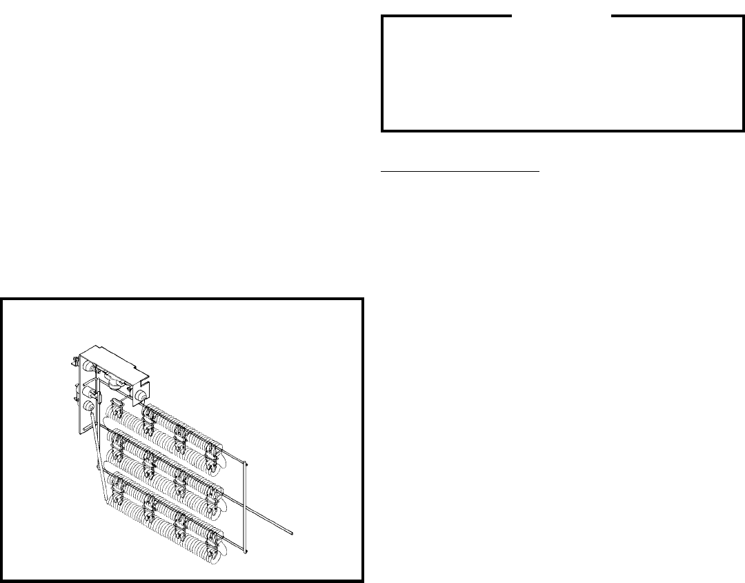
HEATING ELEMENT (See Figure 44)
All heat pumps and electric heat models are equipped with a
heating element with the exception of the YS09J10. The "YS",
"ES" and "EK12" models are equipped with a 3.3 KW element.
The "YM", "EM" and "EK18" models are equipped with a 4.0
KW element. The "YL" and "EL" models are equipped with a
5.2 KW element.
The heating element contains a fuse link and a heater limit
switch. The fuse link is in series with the power supply and will
open and interrupt the power when the temperature reaches
161.6°F, or a short circuit occurs in the heating element. Once
the fuse link separates, a new fuse link must be installed.
NOTE: Always replace with the exact replacement.
The heater element has a high limit control. This control is a
bimetal thermostat mounted in the top of the heating element.
Should the fan motor fail or filter become clogged, the high
limit control will open and interrupt power to the heater before
reaching an unsafe temperature condition.
The control is designed to open at 110°F ±6°F. Test continuity
below 110°F and for open above 110°F.
The heating element for the "Y" model is energized by an
outdoor thermostat. The outdoor thermostat is adjusted at a
predetermined temperature to bring on the heating element
and turn off the compressor. The room thermostat will then
control the cycling of the element when the selected indoor
temperature is reached.
Testing of the elements can be made with an ohmmeter across
the terminals after the connecting wires have been removed.
A cold resistance reading of approximately 14.5 ohms for the
3.3 KW heater, 11.9 ohms for the 4.0 KW heater and 9.15
ohms for the 5.2 KW heater should be registered.
SEALED REFRIGERATION SYSTEM REPAIRS
IMPORTANT
ANY SEALED SYSTEM REPAIRS TO HEAT PUMP
MODELS REQUIRES THE INSTALLATION OF A
SUCTION LINE DRIER IN THE SUCTION LINE
BETWEEN THE EVAPORATOR AND THE REVERSING
VALVE.
EQUIPMENT REQUIRED
1. Voltmeter
2. Ammeter
3. Ohmmeter
4. E.P.A. Approved Refrigerant Recovery System.
5. Vacuum Pump (capable of 200 microns or less vacuum.)
6. Acetylene Welder
7. Electronic Halogen Leak Detector (G.E. Type H-6 or
equivalent.)
8. Accurate refrigerant charge measuring device such as:
a. Balance Scales - 1/2 oz. accuracy
b. Charging Board - 1/2 oz. accuracy
9. High Pressure Gauge - (0 - 400 lbs.)
10. Low Pressure Gauge - (30 - 150 lbs.)
11. Vacuum Gauge - (0 - 1000 microns)
VALVE, DRAIN PAN (See Figure 43)
During the cooling mode of operation, condensate which
collects in the drain pan is picked up by the condenser fan
blade and sprayed onto the condenser coil. This assists in
cooling the refrigerant plus evaporating the water.
During the heating mode of operation, it is necessary that
water be removed to prevent it from freezing during cold
outside temperatures. This could cause the condenser fan
blade to freeze in the accumulated water and prevent it from
turning.
To provide a means of draining this water, a bellows type
drain valve is installed over a drain opening in the base pan.
This valve is temperature sensitive and will open when the
outside temperature reaches 40°F. The valve will close
gradually as the temperature rises above 40°F to fully close
at 60°F.
Figure 44 - Heating Element

30
HERMETIC COMPONENT REPLACEMENT
The following procedure applies when replacing components
in the sealed refrigeration circuit or repairing refrigerant leaks.
(Compressor, condenser, evaporator, capillary tube, refrigerant
leaks, etc.)
1. Recover the refrigerant from the system at the process
tube located on the high side of the system by installing
a line tap on the process tube. Apply gauge from process
tube to EPA approved gauges from process tube to
EPA approved recovery system. Recover CFC's in
system to at least 5%.
2. Cut the process tube below pinch off on the suction
side of the compressor.
3. Connect the line from the nitrogen tank to the suction
process tube.
4. Drift dry nitrogen through the system and un-solder the
more distant connection first. (Filter drier, high side
process tube, etc.)
5. Replace inoperative component, and always install a
new filter drier. Drift dry nitrogen through the system
when making these connections.
6. Pressurize system to 30 PSIG with proper refrigerant
and boost refrigerant pressure to 150 PSIG with dry
nitrogen.
7. Leak test complete system with electric halogen leak
detector, correcting any leaks found.
8. Reduce the system to zero gauge pressure.
9. Connect vacuum pump to high side and low side of
system with deep vacuum hoses, or copper tubing. (Do
not use regular hoses.)
10. Evacuate system to maximum absolute holding
pressure of 200 microns or less. NOTE: This process
can be speeded up by use of heat lamps, or by breaking
the vacuum with refrigerant or dry nitrogen at 5,000
EQUIPMENT MUST BE CAPABLE OF:
1. Recovery CFC's as low as 5%.
2. Evacuation from both the high side and low side of the
system simultaneously.
3. Introducing refrigerant charge into high side of the sys-
tem.
4. Accurately weighing the refrigerant charge actually in-
troduced into the system.
5. Facilities for flowing nitrogen through refrigeration tub-
ing during all brazing processes.
microns. Pressure system to 5 PSIG and leave in
system a minimum of 10 minutes. Release refrigerant,
and proceed with evacuation of a pressure of 200
microns or less.
11. Break vacuum by charging system from the high side
with the correct amount of refrigerant specified. This
will prevent boiling the oil out of the crankcase.
NOTE: If the entire charge will not enter the high side,
allow the remainder to enter the low side in
small increments while operating the unit.
12. Restart unit several times after allowing pressures to
stabilize. Pinch off process tubes, cut and solder the
ends. Remove pinch off tool, and leak check the
process tube ends.
SPECIAL PROCEDURE IN THE CASE OF
COMPRESSOR MOTOR BURNOUT
1. Recover all refrigerant and oil from the system.
2. Remove compressor, capillary tube and filter drier
from the system.
3. Flush evaporator condenser and all connecting tubing
with dry nitrogen or equivalent, to remove all
contamination from system. Inspect suction and
discharge line for carbon deposits. Remove and clean
if necessary.
4. Reassemble the system, including new drier strainer
and capillary tube.
5. Proceed with processing as outlined under hermetic
component replacement.
ROTARY COMPRESSOR SPECIAL
TROUBLESHOOTING AND SERVICE
Basically, troubleshooting and servicing rotary compressors
is the same as on the reciprocating compressor with only a
few exceptions.
1. Because of the spinning motion of the rotary, the
mounts are critical. If vibration is present, check the
mounts carefully.
2. The electrical terminals on the rotary are in a different
order than the reciprocating compressors. The
terminal markings are on the cover gasket. Use your
wiring diagram to insure correct connections.
REFRIGERANT CHARGING
NOTE: BECAUSE THE RAC SYSTEM IS A SEALED
SYSTEM, SERVICE PROCESS TUBES WILL HAVE TO
BE INSTALLED. FIRST INSTALL A LINE TAP AND
REMOVE REFRIGERANT FROM SYSTEM. MAKE
NECESSARY SEALED SYSTEM REPAIRS AND
VACUUM SYSTEM. CRIMP PROCESS TUBE LINE AND
SOLDER END SHUT. DO NOT LEAVE A SERVICE
VALVE IN THE SEALED SYSTEM.

31
NOTE: In order to access the sealed system it will be necessary to install Schrader type fittings to the process
tubes on the discharge and suction of the compressor. Proper recovery refrigerant procedures need to be adhered
to as outlined in EPA Regulations. THIS SHOULD ONLY BE ATTEMPTED BY QUALIFIED SERVICE PERSONNEL.
An undercharged system will result in poor performance (low
pressures, etc.) in both the heating and cooling cycle.
Whenever you service a unit with an undercharge of
refrigerant, always suspect a leak. The leak must be repaired
before charging the unit.
To check for an undercharged system, turn the unit on, allow
the compressor to run long enough to establish working
pressures in the system (15 to 20 minutes).
During the cooling cycle you can listen carefully at the exit of
the metering device into the evaporator; an intermittent hissing
and gurgling sound indicates a low refrigerant charge.
Intermittent frosting and thawing of the evaporator is another
indication of a low charge, however, frosting and thawing can
also be caused by insufficient air over the evaporator.
Checks for an undercharged system can be made at the
compressor . If the compressor seems quieter than normal, it
is an indication of a low refrigerant charge. A check of the
amperage drawn by the compressor motor should show a
lower reading. (Check the Unit Specification.) After the unit
has run 10 to 15 minutes, check the gauge pressures.
Gauges connected to system with an undercharge will have
low head pressures and substantially low suction pressures.
Undercharged Refrigerant Systems
Proper refrigerant charge is essential to proper unit
operation. Operating a unit with an improper refrigerant
charge will result in reduced performance (capacity) and/or
efficiency. Accordingly, the use of proper charging methods
during servicing will insure that the unit is functioning as
designed and that its compressor will not be damaged.
Too much refrigerant (overcharge) in the system is just as
bad (if not worse) than not enough refrigerant
(undercharge). They both can be the source of certain
compressor failures if they remain uncorrected for any
period of time. Quite often, other problems (such as low air
flow across evaporator, etc.) are misdiagnosed as
refrigerant charge problems. The refrigerant circuit
diagnosis chart will assist you in properly diagnosing these
systems.
An overcharged unit will at times return liquid refrigerant
(slugging) back to the suction side of the compressor
eventually causing a mechanical failure within the compressor.
This mechanical failure can manifest itself as valve failure,
bearing failure, and/or other mechanical failure. The specific
type of failure will be influenced by the amount of liquid being
returned, and the length of time the slugging continues.
Not enough refrigerant (Undercharge) on the other hand, will
cause the temperature of the suction gas to increase to the
point where it does not provide sufficient cooling for the
compressor motor. When this occurs, the motor winding
temperature will increase causing the motor to overheat and
possibly cycle open the compressor overload protector.
Continued overheating of the motor windings and/or cycling
of the overload will eventually lead to compressor motor or
overload failure.
METHOD OF CHARGING
The acceptable method for charging the RAC system is the
Weighed in Charge Method. The weighed in charge method
is applicable to all units. It is the preferred method to use, as
it is the most accurate.
The weighed in method should always be used whenever a
charge is removed from a unit such as for a leak repair,
compressor replacement, or when there is no refrigerant
charge left in the unit. To charge by this method, requires the
following steps:
1. Install a piercing valve to remove refrigerant from the
sealed system. (Piercing valve must be removed from
the system before recharging.)
2. Recover Refrigerant in accordance with EPA regulations.
3. Install a process tube to sealed system.
4. Make necessary repairs to system.
5. Evacuate system to 250 - 300 microns or less.
6. Weigh in refrigerant with the property quantity of R-22
refrigerant.
7. Start unit, and verify performance.
8. Crimp the process tube and solder the end shut.
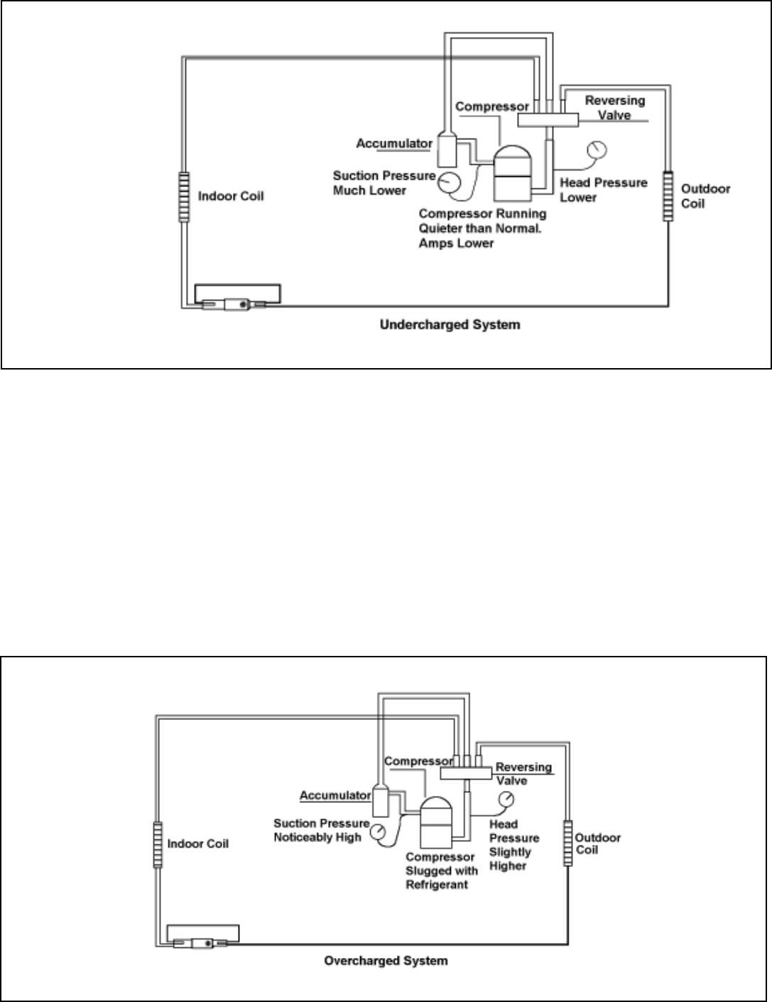
32
Overcharged Refrigerant Systems
Compressor amps will be near normal or higher.
Noncondensables can also cause these symptoms. To
confirm, remove some of the charge, if conditions improve,
system may be overcharged. If conditions don’t improve,
Noncondensables are indicated.
Whenever an overcharged system is indicated, always make
sure that the problem is not caused by air flow problems.
Improper air flow over the evaporator coil may indicate some
of the same symptoms as an overcharged system.
An over charge can cause the compressor to fail, since it would
be "slugged" with liquid refrigerant.
The charge for any system is critical. When the compressor
is noisy, suspect an overcharge, when you are sure that the
air quantity over the evaporator coil is correct. Icing of the
evaporator will not be encountered because the refrigerant
will boil later if at all. Gauges connected to system will usually
have higher head pressure (depending upon amount of
overcharge). Suction pressure should be slightly higher.
NOTE: Heat pump
refrigeration
drawing
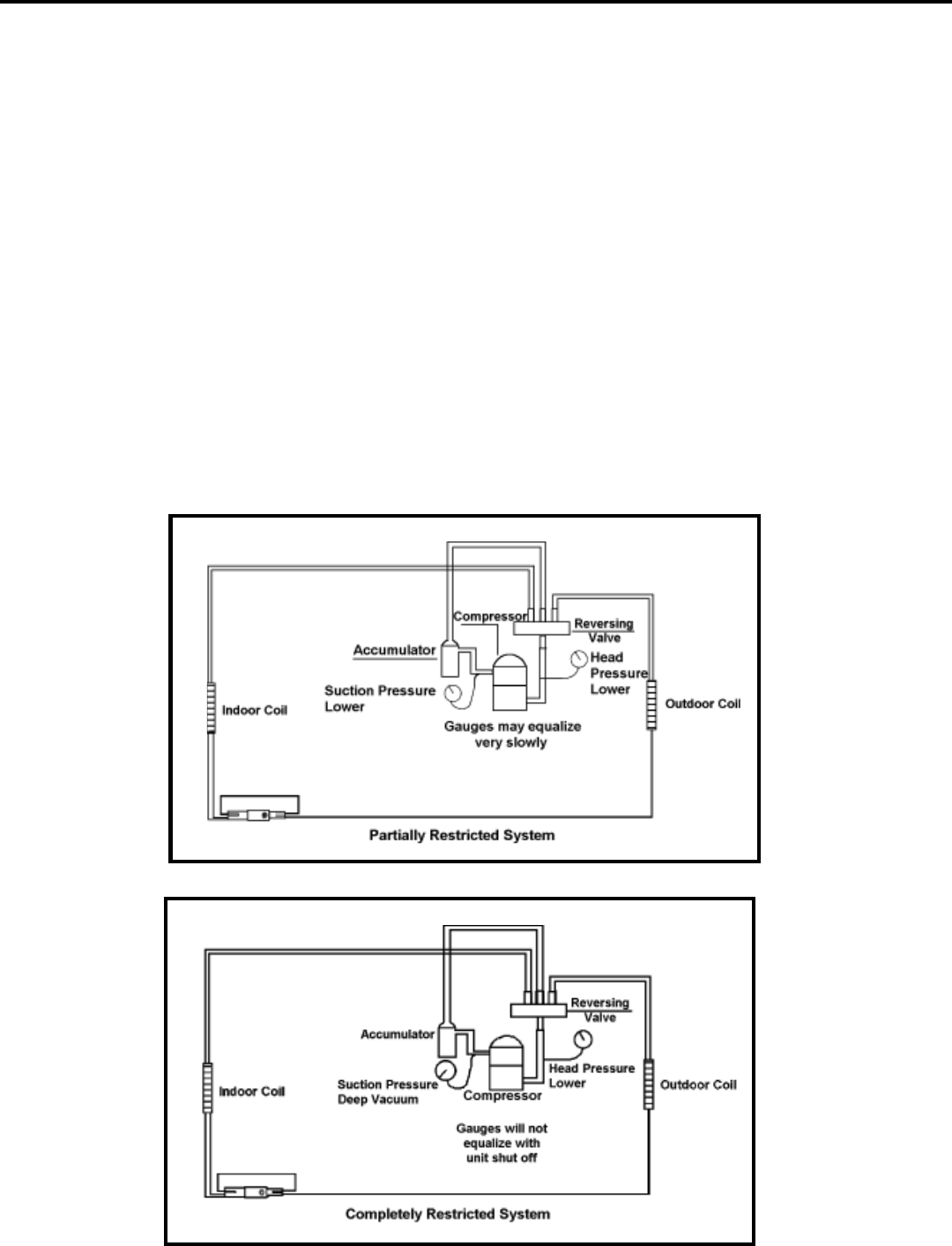
33
A quick check for either condition begins at the evaporator.
With a partial restriction, there may be gurgling sounds at the
metering device entrance to the evaporator. The evaporator
in a partial restriction could be partially frosted or have an ice
ball close to the entrance of the metering device. Frost may
continue on the suction line back to the compressor.
Often a partial restriction of any type can be found by feel, as
there is a temperature difference from one side of the restriction
to the other.
With a complete restriction, there will be no sound at the
metering device entrance. An amperage check of the
compressor with a partial restriction may show normal current
when compared to the unit specification. With a complete
restriction the current drawn may be considerably less than
normal, as the compressor is running in a deep vacuum (no
load.) Much of the area of the condenser will be relatively cool
since most or all of the liquid refrigerant will be stored there.
The following conditions are based primarily on a system in
the cooling mode.
Restricted Refrigerant System
Troubleshooting a restricted refrigerant system can be
difficult. The following procedures are the more common
problems and solutions to these problems. There are two
types of refrigerant restrictions: Partial restrictions and
complete restrictions.
A partial restriction allows some of the refrigerant to circulate
through the system.
With a complete restriction there is no circulation of refrigerant
in the system.
Restricted refrigerant systems display the same symptoms
as a "low-charge condition."
When the unit is shut off, the gauges may equalize very slowly.
Gauges connected to a completely restricted system will run
in a deep vacuum. When the unit is shut off, the gauges will
not equalize at all.
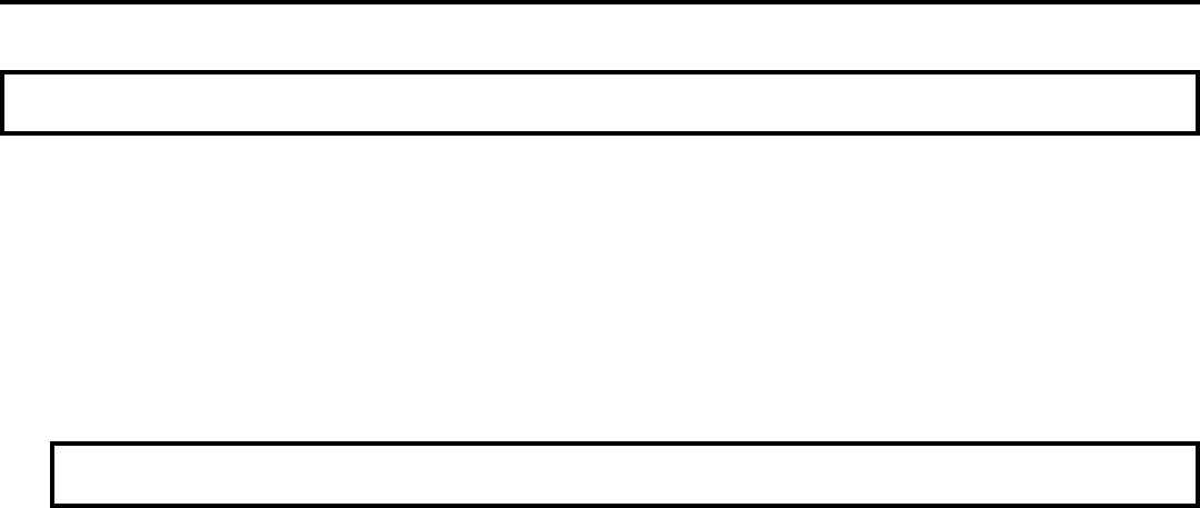
34
Routine Maintenance
1. Clean the unit air intake filter at least every 250 to 300 fan hours of operation or when the unit's indicator light is on if so
equipped. Clean the filters with a mild detergent in warm water and allow to dry thoroughly before reinstalling.
2. The indoor coil (evaporator coil), the outdoor coil (condenser coil) and base pan should be inspected periodically (yearly
or bi-yearly) and cleaned of all debris (lint, dirt, leaves, paper, etc.). Clean the coils and base pan with a soft brush and
compressed air or vacuum. If using a pressure washer, be careful not to bend the aluminium fin pack. Use a sweeping
up and down motion in the direction of the vertical aluminum fin pack when pressure cleaning coils. Cover all electrical
components to protect them from water or spray. Allow the unit to dry thoroughly before reinstalling it in the sleeve.
NOTE: Units are to be inspected and serviced by qualified service personnel only.
Inspect the indoor blower housing, evaporator blade, condenser fan blade, and condenser shroud periodically (yearly or
bi-yearly) and clean of all debris (lint, dirt, mold, fungus, etc.) Clean the blower housing area and blower wheel with an
antibacterial / antifungal cleaner. Use a biodegradable cleaning agent and degreaser on condenser fan and condenser
shroud. Use warm or cold water when rinsing these items. Allow all items to dry thoroughly before reinstalling them.
3. Periodically (at least yearly or bi-yearly): inspect all control components, both electrical and mechanical, as well as the
power supply. Use proper testing instruments (voltmeter, ohmmeter, ammeter, wattmeter, etc.) to perform electrical
tests. Use an air conditioning or refrigeration thermometer to check room, outdoor and coil operating temperatures. Use
a sling psychrometer to measure wet bulb temperatures indoors and outdoors.
4. Inspect the surrounding area (inside and outside) to ensure that the units' clearances have not been compromised or
altered.
5. Inspect the sleeve and drain system periodically (at least yearly or bi-yearly) and clean of all obstructions and debris.
Clean both areas with an antibacterial and antifungal cleaner. Rinse both items thoroughly with water and ensure that
the drain outlets are operating correctly. Check the sealant around the sleeve and reseal areas as needed.
6. Clean the front cover when needed. Use a mild detergent. Wash and rinse with warm water. Allow it to dry thoroughly
before reinstalling it in the chassis.
NOTE: Do not use a caustic coil cleaning agent on coils or base pan. Use a biodegradable cleaning agent and
degreaser.
35
Troubleshooting Touch Test Chart: To Service Reversing Valves
MALFUNCTION OF VALVE
No voltage to coil.
Defective coil.
Low charge.
Pressure differential too high.
Pilot valve okay. Dirt in one
bleeder hole.
Piston cup leak
Hot
Hot
Warm
Hot
Hot
Hot
Hot
Hot
Hot
Hot
Hot
Hot
Hot
Warm
Cool
Cool
Cool
Warm
Warm
Hot
Hot
Cool
Cool
Cool
Cool
Cool
Cool
Cool
Raise head pressure, operate solenoid to free.
If still no shift, replace valve.
Raise head pressure, operate solenoid to free
partially clogged port. If still no shift, replace
valve.
Replace compressor
Check unit for correct operating pressures and
charge. Raise head pressure. If no shift, use
valve with smaller port.
Replace valve
Raise head pressure, operate solenoid. If no
shift, replace valve.
Replace valve
Raise head pressure, operate solenoid. If no
shift, use valve with smaller ports.
Raise head pressure, operate solenoid. If no
shift, replace valve.
Operate valve several times, then recheck. If
excessive leak, replace valve.
Operate valve several times, then recheck. If
excessive leak, replace valve.
Stop unit. Will reverse during equalization
period. Recheck system
Raise head pressure, operate solenoid to free
dirt. If still no shift, replace valve.
Raise head pressure, operate solenoid.
Remove valve and wash out. Check on air
before reinstalling, if no movement, replace
valve. Add strainer to discharge tube. Mount
valve horizontally.
Stop unit. After pressures equalize, restart with
solenoid deenergized. If valve shifts, reattempt
with compressor running. If it still will not reverse
while running, replace the valve.
Replace valve.
Replace compressor
Repair electrical circuit.
Replace coil.
Repair leak, recharge system.
Recheck system.
Deenergize solenoid, raise head pressure,
reenergize solenoid to break dirt loose. If
unsuccessful, remove valve, wash out. Check
on air before installing. If no movement, replace
valve, add strainer to discharge tube, mount
valve horizontally.
Stop unit. After pressures equalize, restart with
solenoid energized. If valve shifts, reattempt
with compressor running. If still no shift, replace
valve.
Check Electrical circuit and coil
Check refrigeration charge
Hot
Cool Cool,
as (2)
*TVB
Hot Hot,
as (1)
SUCTION TUBE
to Compressor
Valve will
not shift
from cool to
heat.
Valve will
not shift
from cool to
heat.
Starts to
shift but
does not
complete
reversal.
Will not shift
from heat to
cool.
Apparent
leap in
heating.
Clogged pilot tubes.
Both ports of pilot open. (Back seat
port did not close).
Defective Compressor.
Not enough pressure differential at
start of stroke or not enough flow to
maintain pressure differential.
Body damage.
Both ports of pilot open.
Body damage.
Valve hung up at mid-stroke. Pumping
volume of compressor not sufficient to
maintain reversal.
Both ports of pilot open.
Piston needle on end of slide leaking.
Pilot needle and piston needle leaking.
Pressure differential too high.
Clogged pilot tube.
Dirt in bleeder hole.
Piston cup leak.
Defective pilot.
Defective compressor.
*TVB
Hot
Warm
Hot
Hot
Hot
Hot
*TVB
**
WVB
*TVB
*TVB
*TVB
Hot
*TVB
NORMAL FUNCTION OF VALVE
DISCHARGE TUBE
from Compressor
Tube to INSIDE
COIL
Tube to OUTSIDE
COIL
LEFT Pilot
Capillary Tube
RIGHT Pilot
Capillary Tube
VALVE
OPERATING
CONDITION
*TVB
Hot
*TVB
*TVB
Hot
*TVB
Hot
*TVB
**
WVB
*TVB
Hot
Hot
Hot
Warm
Hot,
as (1)
Hot,
as (1)
Warm,
as (1)
Hot
Hot
Hot
Hot
Cool,
as (2)
Cool,
as (2)
Cool,
as (2)
Cool,
as (2)
Cool,
as (2)
Cool,
as (2)
Cool,
as (2)
Cool,
as (2)
Cool,
as (2)
Cool,
as (2)
Warm
Warm
Hot
Hot,
Hot,
as (1)
Hot,
as (1)
Hot,
as (1)
Hot,
as (1)
Hot,
as (1)
Hot,
as (1)
Warm,
as (1)
NOTES:
* TEMPERATURE OF VALVE BODY
** WARMER THAN VALVE BODY
1 2 3 4 5 6 POSSIBLE CAUSES CORRECTIONS
Normal Hot Cool Cool Hot *TVB TVB
Cooling as (2) as (1)
Normal Heating Hot Cool Hot Cool *TVB TVB
as (1) as (2)
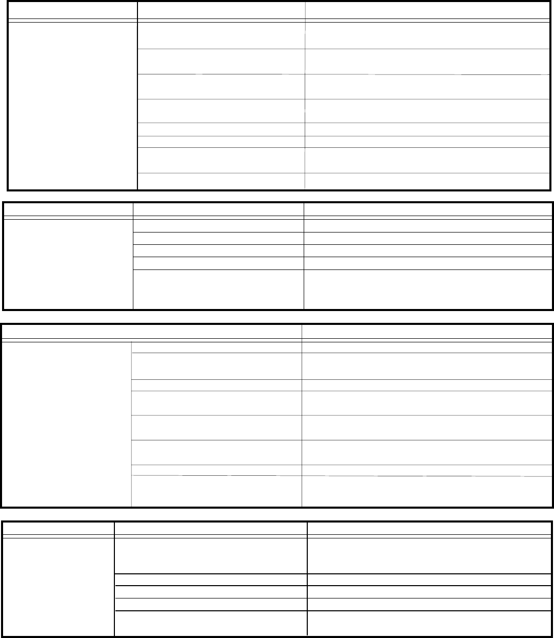
36
Troubleshooting: Cooling
Refer to Sizing Charts.
Set to coldest position. Test thermostat and
replace if necessary.
Clean as recommended in Owner’s Manual.
Use steam or detergents to clean.
Adjust discharge air louvers. Use high fan
speed.
Close doors. Instruct customer on use of this
feature.
Check for leak and make repair.
Check amperage draw against nameplate. If
not conclusive, make pressure test.
Undersized unit.
Thermostat open or inoperative.
Dirty filter.
Dirty or plugged condenser or
evaporator coil.
Poor air circulation in area being
cooled.
Fresh air or exhaust air door open
on applicable models.
Low capacity – undercharge.
Compressor not pumping properly.
Does not cool, or cools
only slightly.
POSSIBLE CAUSE
PROBLEM TO CORRECT
Test switch and replace in inoperative.
Refer to applicable wiring diagram.
Test capacitor and replace if inoperative.
Test switch and replace if inoperative.
Test fan motor and replace if inoperative. (Be
sure internal overload has had time to reset.)
Inoperative system switch.
Broken, loose or incorrect wiring.
Open Capacitor.
Fan speed switch open.
Inoperative fan motor.
Fan motor
does not run.
TO CORRECT
POSSIBLE CAUSE
PROBLEM
Low voltage.
Thermostat not set cold enough or
inoperative.
Compressor hums but cuts off on
overload.
Open or shorted compressor
windings.
Open overload.
Open capacitor.
Inoperative system switch.
Broken, loose or incorrect wiring.
Check for voltage at compressor. 115 volt and 230
volt units will operate at 10% voltage variance
Set thermostat to coldest position. Test thermostat
and replace if inoperative.
Hard start compressor. Direct test compressor. If
compressor starts, add starting components.
Check for continuity and resistance.
Test overload protector and replace if inoperative.
Test capacitor and replace if inoperative.
Test for continuity in all positions. Replace if
inoperative.
Refer to appropriate wiring diagram to check wiring.
Compressor does not
run.
TO CORRECT
POSSIBLE CAUSE
PROBLEM
Unit does not run.
Fuse blown or circuit tripped.
TO CORRECT
Replace fuse, reset breaker. If repeats, check fuse
or breaker size. Check for shorts in unit wiring and
components.
Plug in power cord
Set switch correctly.
Test for continuity in each switch position.
Check wiring and connections. Reconnect per wiring
diagram.
Power cord not plugged in.
System switch in "Off" position.
Inoperative system switch.
Loose or disconnected wiring at switch or
other components.
PROBLEM
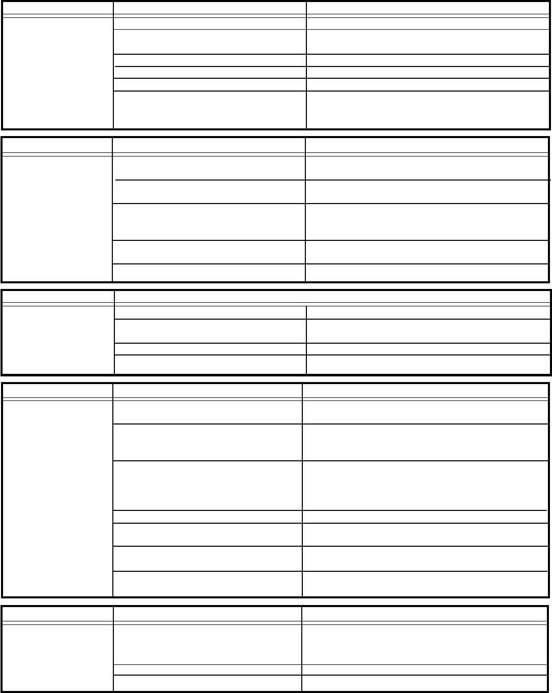
37
Compressor runs
continually.
Does not cycle off.
TO CORRECT:
Unit undersized. Test cooling performance of unit.
Replace with larger unit.
Check for partially iced coil. Check temperature split
across coil.
Check for oil at silver soldered connections. Check
for partially iced coil. Check split across coil. Check
for low running amperage.
Check operation of thermostat. Replace if contacts
remain closed.
Refer to appropriate wiring diagram.
PROBLEM POSSIBLE CAUSE
Excessive heat load.
Restriction in line.
Refrigerant leak.
Thermostat contacts stuck
Thermostat incorrectly wired.
Replace thermostat.
Turn to higher temperature setting to see if the unit
cycles off.
Refer to appropriate wiring diagram.
Refer to Sizing Chart.
TO CORRECT:PROBLEM
Thermostat contacts stuck.
Thermostat set at coldest point.
Incorrect wiring.
Unit undersized for area to be cooled.
POSSIBLE CAUSE
Thermostat does not
turn unit off.
PROBLEM TO CORRECT
Clean as recommended in Owner’s Manual.
Check for dirty or obstructed coil - clean as re-
quired.
Test for shorted thermostat or stuck contacts.
De-ice coil and check for leak.
Test fan motor and replace if inoperative.
De-ice coil. Check temperature differential across
coil. Touch test coil return bends for same tempera-
ture. Test for low running current.
POSSIBLE CAUSE
Evaporator coil
freezes up.
Dirty filter.
Restricted air flow.
Inoperative thermostat.
Short of refrigerant.
Inoperative fan motor.
Partially restricted capillary.
POSSIBLE CAUSE TO CORRECT
Check operation of unit. Replace overload if
system operation is satisfactory.
Allow a minimum of two (2) minutes for pressures
to equalize before attempting to restart. Instruct
customer of waiting period.
Check voltage with unit operating. Check for other
appliances on circuit. Air conditioner should be on
separate circuit for proper voltage, and be fused
separately.
Refer to appropriate wiring diagram.
Check by substituting a known good capacitor of
correct rating.
Check for proper fan speed or blocked condenser.
Check for kinked discharge line or restricted condenser.
Check amperage.
Overload inoperative. Opens too soon.
PROBLEM
Compressor attempts
to start, or runs for
short periods only.
Cycles on overload.
Compressor attempts to start before
system pressures are equalized.
Low or fluctuating voltage.
Incorrect wiring.
Shorted or incorrect capacitor.
Restricted or low air flow through
condenser coil.
Compressor running abnormally hot.
Place jumper across thermostat terminals to check
if unit operates. If unit operates, replace thermostat.
Check as above.
Refer to appropriate wiring diagram.
POSSIBLE CAUSE
Loss of charge in thermostat bulb.
Loose or broken parts in thermostat.
Incorrect wiring.
TO CORRECTPROBLEM
Thermostat does not
turn unit on.
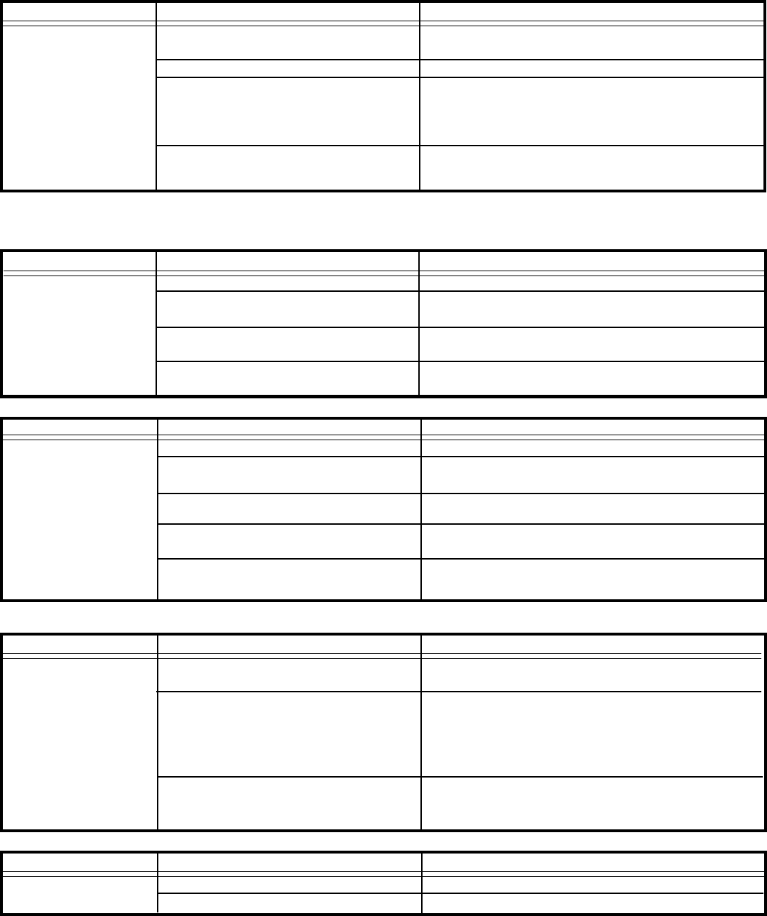
38
Refer to Installation Instructions for proper
installation.
Reposition - adjust motor mount.
Check that compressor grommets have not
deteriorated. Check that compressor mounting
parts are not missing, and that shipping blocks
have been removed.
Check assembly and parts for looseness,
rubbing and rattling.
TO CORRECT
POSSIBLE CAUSE
PROBLEM
Noisy operation.
Poorly installed unit.
Fan blade striking chassis.
Compressor vibrating.
Improperly mounted or loose cabinet
parts.
Clean obstructed drain trough.
Evaporator drain pan broken or cracked. Reseal or
replace.
Check Installation Instructions. Reseal as required.
Dirty evaporator coil - clean.
Very high humidity level.
TO CORRECTPOSSIBLE CAUSE
PROBLEM
Water leaks into room.
Evaporator drain pan overflowing.
Condensation forming on base pan.
Poor installation resulting in rain
entering room.
Condensation on discharge grilles.
PROBLEM POSSIBLE CAUSE TO CORRECT
Replace thermostat.
Check gasket. Reposition or replace.
Clean and advise customer of periodic cleaning of
filter.
Replace tubular insulation on bulb.
(Applicable models.)
Adjust bulb bracket.
(Applicable models.)
Thermostat differential too narrow.
Plenum gasket not sealing, allowing
discharge air to short cycle thermostat.
Restricted coil or dirty filter.
Tubular insulation missing from top of
thermostat bulb.
Thermostat bulb touching thermostat
bulb support bracket.
Thermostat short
cycles.
TO CORRECT
Refer to appropriate wiring diagram.
PROBLEM Anticipator (resistor) wire disconnected
at thermostat or system switch.
Anticipator (resister shorted or open).
(Applicable models.)
Partial loss of charge in thermostat
bulb causing a wide differential.
POSSIBLE CAUSE
Disconnect plug from outlet. Remove resistor from
bracket. Insert plug and depress "Cool" and "Fan -
Auto (MoneySaver)” buttons. Place thermostat to
warmest setting. Feel resistor for temperature.
If no heat, replace resistor.
Replace thermostat.
Prolonged off-cycles.
(automatic operation)
PROBLEM POSSIBLE CAUSE TO CORRECT
Switches from
cooling to heating. Change room thermostat.
Refer to appropriate wiring diagram.
Thermostat sticking.
Incorrect wiring.
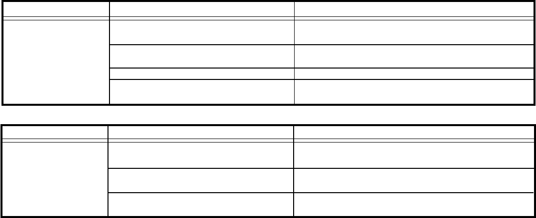
39
TO CORRECTPOSSIBLE CAUSE
PROBLEM
Repair, clean or replace as required.
Evaporator drain pan cracked or
obstructed.
Water in compressor area.
Obstructed condenser coil.
Fan blade and slinger ring improperly
positioned.
Detach shroud from pan and coil. Clean and
remove old sealer. Reseal, reinstall and check.
Steam clean.
Adjust fan blade to 1/2" clearance from condenser
coil.
Outside water leaks.
High indoor
humidity.
TO CORRECT
POSSIBLE CAUSE
PROBLEM
Adjust louvers for best possible air circulation
Operate in "Fan-Auto (MoneySaver)" position.
Advise customer.
Insufficient air circulation in air condi-
tioned area.
Oversized unit.
Inadequate vapor barrier in building
structure, particularly floors.
40
Troubleshooting: Heating (Heat pumps)
PROBLEM TO CORRECTPOSSIBLE CAUSE
Set thermostat to a warmer position.
Replace — do not attempt to adjust.
Check compressor wiring. Check for open internal
or external overload. Check wiring.
Test system switch
Thermostat setting.
Defective thermostat.
Compressor not operating.
Defective system switch.
No heating — fan
operates.
Clean as recommended in Owner’s Manual.
Check if outdoor thermostat is energizing the heating
element at its predetermined temperature setting
Check control setting.
TO CORRECT
POSSIBLE CAUSE
PROBLEM
Restricted filter.
Outdoor thermostat.
(Applicable models.)
Fresh air or exhaust door open.
Insufficient heating.
TO CORRECT
POSSIBLE CAUSE
PROBLEM
Check continuity of switch.
Check applicable wiring diagram.
Inoperative system switch.
Incorrect wiring.
Fan operates in
"constant" position, but
not in "automatic"
(MoneySaver).
TO CORRECT
PROBLEM POSSIBLE CAUSE
Incorrect differential setting. Replace thermostat.
Check voltage to resistor. If voltage okay, remove
resistor from thermostat bulb block. With current on,
feel resistor for warmth. If no heat can be felt,
replace anticipator.
Defective thermostat.
Heat anticipator (resistor) shorted.
(Applicable models)
Temperature varies from
comfortable to overly
warm.
TO CORRECT
PROBLEM POSSIBLE CAUSE
Room temperature
uneven.
(Heating cycle)
Disconnect power to unit. Remove resistor from
thermostat bulb block. Plug in unit and allow to
operate. Feel resistor for heat. If no heat is felt,
replace resistor.
Replace thermostat and check.
Refer to appropriate wiring diagram. Resistor is
energized during the "on" cycle of compressor or
fan.
Heat anticipator (resistor) shorted.
(Applicable models.)
Wide differential — partial loss of ther-
mostat bulb charge.
Incorrect wiring.
TO CORRECT
POSSIBLE CAUSE
PROBLEM Refer to appropriate wiring diagram.
Check for voltage at "TM" and "TM1" on timer. If
voltage, replace control.
If outside coil temperature is 25° F or below, and
preselected time limit has elapsed, replace the
defrost control.
If the contacts remain closed between terminals "2"
and "3" of the defrost control after preselected time
interval has passed, replace control.
Reinstall and assure that good bulb to coil contact is
made.
Incorrect wiring.
Defrost control timer motor not advanc-
ing.
Defrost control out of calibration.
Defrost control contacts stuck.
Defrost control bulb removed from coil,
or not making good coil contact.
Unit will not defrost.
41
Unit does not heat
adequately.
Outdoor thermostat does not cut off
compressor at the preselected tem-
perature and bring on heating element.
Fresh air or exhaust door open.
Dirty filter.
Unit undersized.
Defective thermostat - replace.
Check if operating properly. Instruct customer
on proper use of control.
Clean as recommended in Owner’s Manual.
Check heat rise across coil. Refer to perfor-
mance data sheet on heat rise at various
outdoor ambients. If heat rise is satisfactory,
check if insulation can be added to attic or
walls.
PROBLEM POSSIBLE CAUSE TO CORRECT
Refer to applicable wiring diagram.
Check for continuity of coil.
Block condenser coil and switch unit to cooling.
Allow pressure to build up in system, then
switch to heating. If valve fails to shift, replace
valve.
Check for continuity of system switch.
Unit cools when
heat is called for.
Incorrect wiring.
Defective solenoid coil.
Reversing valve fails to shift.
Inoperative system switch.
PROBLEM POSSIBLE CAUSE TO CORRECT
TO CORRECT
Defective thermostat — replace.
Check if operating properly. Instruct customer on
proper use of control.
Clean as recommended in Owner’s Manual
Check heat rise across coil. Refer to performance
data sheet on heat rise at various outdoor ambients. If
heat rise is satisfactory, check if insulation can be
added to attic or walls.
POSSIBLE CAUSE
PROBLEM
Outdoor thermostat does not cut off
compressor at the preselected tempera-
ture and bring on the heating element.
Fresh air or exhaust door open.
Dirty filter.
Unit undersized.
Unit does not heat
adequately.
TO CORRECT
Refer to applicable wiring diagram.
Check for continuity of coil.
Block condenser coil and switch unit to cooling. Allow
pressure to build up in the system, then switch to
heating. If valve fails to shift, replace valve.
Check for continuity of system switch.
Incorrect wiring.
Defective solenoid coil.
Reversing valve fails to shift.
Inoperative system switch.
POSSIBLE CAUSEPROBLEM
Unit cools when
heat is called for.
TO CORRECT
Check for partially starved outer coil. Replace heating
capillary tube.
Switch unit several times from heating to cooling.
Check temperature rise across the coil. Refer to
specification sheet for correct temperature rise.
Deenergize solenoid coil, raise head pressure, ener-
gize solenoid to break loose. If valve fails to make
complete shift, replace valve.
POSSIBLE CAUSE
PROBLEM
Heating capillary tube partially
restricted.
Check valve leaking internally.
Reversing valve failing to shift
completely — bypassing hot gas.
Cooling is ad-
equate, but heating
is insufficient.
42
TO CORRECT
Outdoor thermostat.
(Applicable models.)
Compressor will not turn
off and operate on heating
element only during low
outside ambients.
Refer to the heating data on applicable models for
the preselected temperature the compressor shuts
off and the electric element is energized.
POSSIBLE CAUSEPROBLEM
Compressor shuts off on
outdoor thermostat but
element does not heat.
TO CORRECT
Check fuse link for continuity. If defective, replace.
Check amperage draw of element. If no amperage,
replace.
Check voltage to element. If voltage is okay, check
wiring.
Fuse link.
Heating element shorted.
Incorrect wiring.
POSSIBLE CAUSEPROBLEM
43
Troubleshooting: Heating (Cooling/Electric Models)
Check and replace.
Replace capacitor and check.
Check if drain pan valve is open. If not, replace.
Check all connections. Check voltage to fan motor.
POSSIBLE CAUSE
PROBLEM TO CORRECT
Fan motor does not
operate in "Constant"
or "MoneySaver"
position.
Defective motor.
Open or shorted capacitor.
Condenser fan frozen to base pan.
Loose connections.
Cooling adequate,
heating insufficient.
TO CORRECT
Check for partially starved outer coil. Replace
heating capillary tube.
Switch unit several times from heating to cooling.
Check temperature rise across coil. Refer to specifi-
cation sheet for correct temperature rise.
Deenergize solenoid coil, raise head pressure,
energize solenoid to break loose. If valve fails to
make complete shift, replace valve.
Heating capillary tube partially restricted.
Check valve leaking internally.
Reversing valve failing to shift
completely – bypassing hot gas.
POSSIBLE CAUSEPROBLEM
Fan Operates –
heating element does
not come on.
TO CORRECTPOSSIBLE CAUSEPROBLEM
Heater relay or contactor coil open.
Heater relay or contactor stuck open,
pitted or burned.
High limit control open.
Open thermal fuse.
Open or shorted element.
Loose connections.
Check continuity of coil.
Inspect, test continuity with ohmmeter.
Check continuity – if open, replace.
Check continuity. Check reason for failure.
Check voltage across heater terminals. Check
amperage draw of heater.
Tighten all terminals.
PROBLEM POSSIBLE CAUSE TO CORRECT
Heating inadequate.
Restricted filter.
Cycling high limit control.
Exhaust or fresh air door open.
Clean as recommended in Owner’s Manual.
Control is set to open at 155°F ± 5°F and close at
130°F ± 8°F. If cycling prematurely, replace control.
Check position of fresh air door control slide. Adjust
cable if door does not close properly.
Fan operates in "Con-
stant" position, but not in
"Automatic" (Money-
Saver).
PROBLEM POSSIBLE CAUSE TO CORRECT
Fan relay contacts open.
Inoperative system switch.
Loose connection.
Check continuity of fan relay. NOTE: Some models
have the fan relay energized during the heating
cycle while others do not.
Check continuity between terminals "L2" and "3" of
the system switch.
Check connections on system switch and fan relay.
Disconnect power to unit. Remove resistor from
thermostat bulb block. Plug in unit and allow to
operate. Feel resistor for heat. If no heat is felt,
replace resistor.
Replace thermostat and check operation.
Long "off" and "on"
cycles.
POSSIBLE CAUSE
PROBLEM
Heat anticipator (resistor) shorted.
Defective thermostat.
TO CORRECT
44
PROBLEM TO CORRECT
Refer to the heating data on applicable models for
the preselected temperature the compressor shuts
off and the electric element is energized.
POSSIBLE CAUSE
Outdoor thermostat.
(Applicable models.)
Compressor will not
turn off and operate on
heating element only
during low outside
ambients.
Troubleshooting Chart — Cooling
Low Suction Pressure High Suction Pressure Low Head Pressure High Head Pressure
Low Load Conditions High Load Conditions Low Load Conditions High Load Conditions
Low Air Flow Across High Air Flow Across Refrigerant System Low Air Flow Across
Indoor Coil Indoor Coil Restriction Outdoor Coil
Refrigerant System Reversing Valve not Reversing Valve not Overcharged
Restriction Fully Seated Fully Seated
Undercharged Overcharged Undercharged Noncondensables (air)
in System
Moisture in System Defective Compressor Defective Compressor
REFRIGERANT SYSTEM
DIAGNOSIS COOLING
45
Electrical Troubleshooting Chart
(Heat Pump)
Reversing Valve Stuck
Replace the Reversing Valve
Replace the Solenoid Coil
NO
Is the Solenoid Coil Good?
Is Line Voltage
Present at the Solenoid
Is the Selector Switch
Set for Heat?
NO
SYSTEM COOLS WHEN
HEATING IS DESIRED.
YES
HEAT PUMP
YES
Troubleshooting Chart — Heating
Noncondensables (air) in
System
Overcharged
Low Airflow Across
Indoor Coil
Outdoor Ambient Too High
For Operation In Heating
High Head Pressure
REFRIGERANT SYSTEM
DIAGNOSIS – HEATING
Moisture in System Defective Compressor Defective Compressor
Undercharged Overcharged Undercharged
Refrigerant System
Restriction Reversing Valve not
Fully Seated
Low Airflow
Across Outdoor Coil
Outdoor Ambient Too High
for Operation in Heating Refrigerant System
Restriction
Low Suction Pressure High Suction Pressure Low Head Pressure
Reversing Valve not
Fully Seated
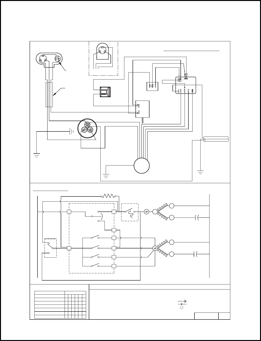
46
MODELS
RS10J10C, RS12J10A-B, RS15J10A, RS16J30A-A, RS18J30A, RM24J30-A
1
2
3
MOTOR MOUNT
TO INNERWALL/
WHITE
BROWN
OR GREEN/YELLOW
TERMINAL
COMPRESSOR
COMPRESSOR
S
R
C
BLACK
BLUE
RED
BLACK
ORIENTATION
MAY VARY.
REFER TO
MARKINGS ON
COMPRESSOR
OVERLOAD
PROTECTOR
BLUE
R
S
C
RED
COMPRESSOR
ALTERNATE
BLACK
COMPRESSOR
WIRE HARNESS
BLACK
OR WHITE BLUE
ANTICIPATOR
RESISTOR
TO CAPACITOR
GREEN
BRACKET
RED
BLUE
TO CHASSIS
CAPACITOR
FAN
c
HERM
GREEN
WIRING DIAGRAM
SUPPLY CORD
TO CAPACITOR
MEDIUM
LOW LOW
SMOOTH CONDUCTOR
OR BROWN
THERMOSTAT
BLUE
RED
BLUE
BROWN
PURPLE
GREY
RED
BLACK
2
1
ROCKER (GE)
SWITCH,
SWITCH
SYSTEM
2
MS
ORANGE
H
L1
C
M
LO
LL
BLACK
BLUE
RED
RED
BLACK
ORANGE
BLUE
FAN
MOTOR
OR GREEN/YELLOW
HIGH
LOW
RIBBED CONDUCTOR
OR BLUE
GREEN
BRACKET
MS M
SCHEMATIC
L1
MS
YES
3
2
L1 1
AR
C
2
2
3H
N0
1
SWITCH POSITION
SWITCH LOGIC
LOW COOL
HI COOL
MED COOL
OFF
FAN ONLY
SYS SW
4
5L
6LL
X = CLOSED
0 = OPEN
CIRCUIT
1234 65
XO XO
XO
OOOO
OO
XO
OX OX OO
OO
O
O
X
O
O
O
O
O
LL COOL XOOO XO
PART NO. REV
- COMBINATION TERMINAL
MTR
COMPR
IDT
21
OVLD
C
MEDIUM
HIGH
OVLD
R
L2
CAP
S
HERM
R
C
L E G E N D
- MONEY SAVER/ROCKER SWITCH
LOW
- COMPRESSOR
- INDOOR THERMOSTAT
- SYSTEM SWITCH
- ANTICIPATOR RESISTOR
- FAN MOTOR
- OVERLOAD PROTECTOR
- CAPACITOR
CAP
MS
AR
SYS SW
OVLD
COMPR
MTR
IDT
CAP
S
FAN C
- GROUND LEAD
- PLASTIC INSULATOR
619-405-00 00
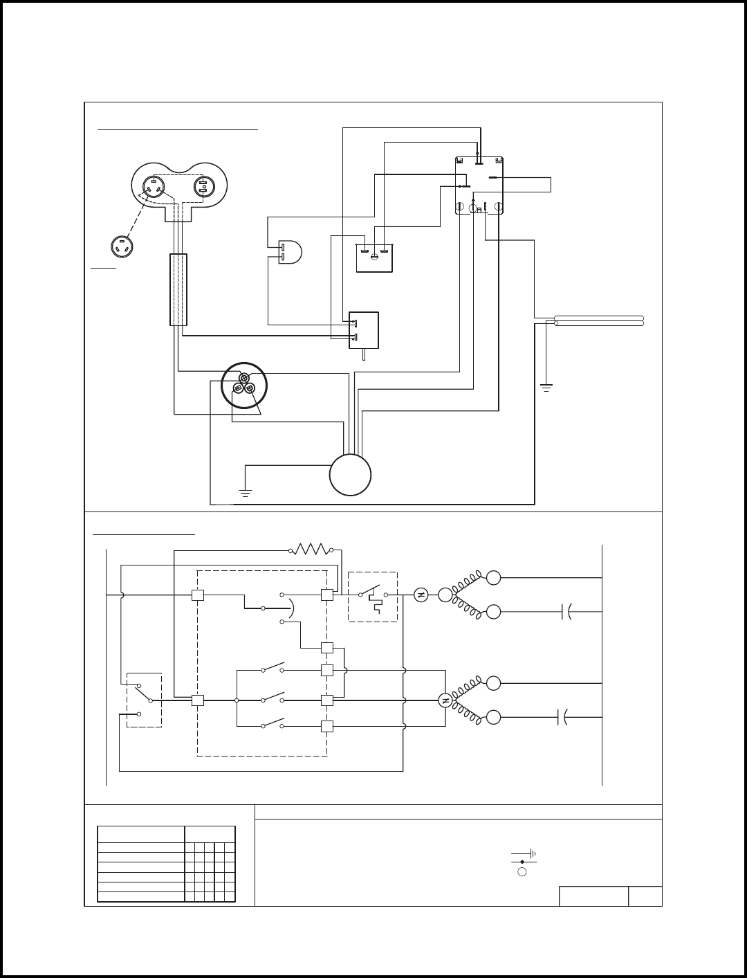
47
MODELS
SQ06J10B-B, SQ06J10B-A, SQ08J10C-A, SQ08J10D-A
GREY
HARNESS, COMPR.
COMPRESSOR
WHITE BLUE
RESISTOR
ANTICIPATOR
CAPACITOR
BLUE
RED
HERM
C
FAN
BLACK
BROWN
WHITE
MOTOR MOUNT
TO INNERWALL/
GREEN
RED
BLUE
BLACK
2
L1
BLUE
RED
PURPLE
CMS
L
M
SWITCH
BROWN
ROCKER (GE)
2
31
RED
SWITCH
H
BLUE
SMOOTH
CONDUCTOR
SYSTEM
SUPPLY CORD
BLACK
THERMOSTAT
2
1
BLUE
RED
FAN
MOTOR
BRACKET
TO CAPACITOR
GREEN
RIBBED CONDUCTOR
MS M
L1
MS
NO
3
2
L1 1
AR
C
2
2
3H
YES
1
SWITCH LOGIC
SYS SW
4
5L
X = CLOSED
0 = OPEN
PART NO. REV.
- COMBINATION TERMINAL
MTR
COMPR
IDT
OVLD
OVLD
L2
CAP
HERM C
L E G E N D
- MONEY SAVER/ROCKER SWITCH
- COMPRESSOR
- INDOOR THERMOSTAT
- SYSTEM SWITCH
- ANTICIPATOR RESISTOR
- FAN MOTOR
- OVERLOAD PROTECTOR
- CAPACITOR
CAP
MS
AR
SYS SW
OVLD
COMPR
MTR
IDT
CAP
FAN C
- GROUND LEAD
- PLASTIC INSULATOR
619-142-15 01
NOTE:
OPTIONAL
CONFIGURATION
WIRING DIAGRAM
SCHEMATIC
SWITCH POSITION
LOW COOL
HI COOL
MED COOL
OFF 13245
CIRCUIT
XOOO
OO OO
XO
XO XO OX
X
O
O
O
FAN ONLY OX OOO
21C
MEDIUM
HIGH
R
S
R
LOW S
C
R
"F""F"
S
"F"
S
C
R
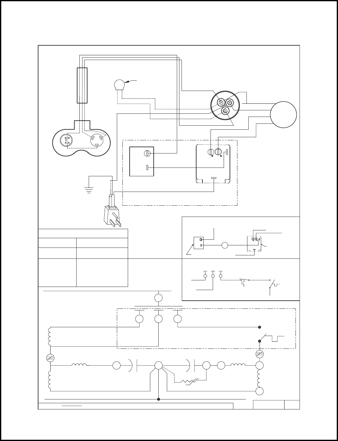
48
MODELS
KQ05J10B-B, KQ05E10-C KQ06J10B-A, KQ06J10B-B, KQ06E10-A, KQ06E10-B
PART NO. REV.
HERM
C
FAN
619-046-01
(OPTIONAL)
PTCR
PTCR (OPTIONAL)
CAPACITOR
COMPRESSOR
FAN MOTOR
SYSTEM SWITCH
SUPPLY CORD
THERMOSTAT
WIRE HARNESS
01
SEE DETAIL " A "
WIRING DIAGRAM
RIBBED (OR BLUE) CONDUCTOR
SCREW
TO GND
GREEN/YELLOW
1
BLACK
2
SMOOTH (OR BROWN) CONDUCTOR
RED
BLUE
WHITE
BROWN
RED
BLACK
H
L
RED
BLACK
C
L1
SCHEMATIC
WHITE
SYSTEM SWITCH SEQUENCE
OFF
CW ROT
LO FAN
HI FAN
LO COOL
HI COOL
CONNECTION
ALL OPEN
L1-L,L1-C
L1-H
L1-L
L1-H,L1-C
BLACK
RED
L
F
BROWN
LINE
DETAIL " A " OPTIONAL WIRING
DETAIL " B " OPTIONAL SCHEMATIC
SYSTEM SWITCH
T\STAT
L1
CONTROL
ANTI-ICE
THERMOSTAT
2
1
BLK
BLK
RED
L H
BLACK
BLK
WHITE
RED BLACK
LC
H
L1
ANTI-ICE
CONTROL
C
SEE DETAIL "B"
H C
CH S C
RIBBED CONDUCTOR
R
LEGEND: = OPTIONAL FACTORY WIRING PTCR = START ASSIST DEVICE
BLACK
BLACK
LINE
R
C
S
BLACK
SYSTEM SWITCH
FAN MOTOR CAPACITOR
T/STAT
COMPRESSOR
OLVD
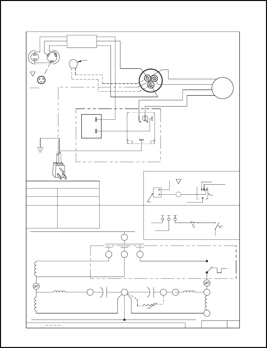
49
MODELS
KQ08J10B-1, KQ08J10B-A, KQ08J10C-A
PTCR
(OPTIONAL)
HERM
C
FAN
04
617-581-04
PTCR (OPTIONAL)
PART NO. REV.
CONFIGURATION
OPTIONAL
NOTE:
BROWN
SEE DETAIL " A "
WIRE HARNESS
SRC
BLUE
BLACK
THERMOSTAT
BLACK
GREEN
TO GND
SCREW
2
1
BLK
BLACK
SUPPLY CORD
BROWN
WIRING DIAGRAM
CAPACITOR
RED
BLACK
BLUE
BLUE RED
FAN MOTOR
RED
BROWN
WHITE
BLACK
DETAIL " A " OPTIONAL WIRING
SYSTEM SWITCH
C
LH
L1
RED
CAPACITOR
C
H
L1
SCHEMATIC
L
L1-H,L1-C
L1-L,L1-C
ALL OPEN
CONNECTION
SYSTEM SWITCH SEQUENCE
HI FAN
LO FAN
CW ROT
OFF
HI COOL
LO COOL
LINE
L1-L
L1-H
SYSTEM SWITCH
= OPTIONAL FACTORY WIRING
FAN MOTOR
WHITE
RED
BLACK
LEGEND:
LINE
BRN
F
C
ANTI-ICE
CONTROL
DETAIL " B " OPTIONAL SCHEMATIC
THERMOSTAT
BLK
BLK OR
2
1
RED L
BLACK
H C CONTROL T/STAT
BLK OR
L1
LHC
BROWN
ANTI-ICE
SYSTEM SWITCH
BLACK
COMPRESSOR
SEE DETAIL "B"
BLUE
PTCR = START ASSIST DEVICE
H S
T\STAT
OLVD
C
R
RED RED
C
R
S
04
04
1
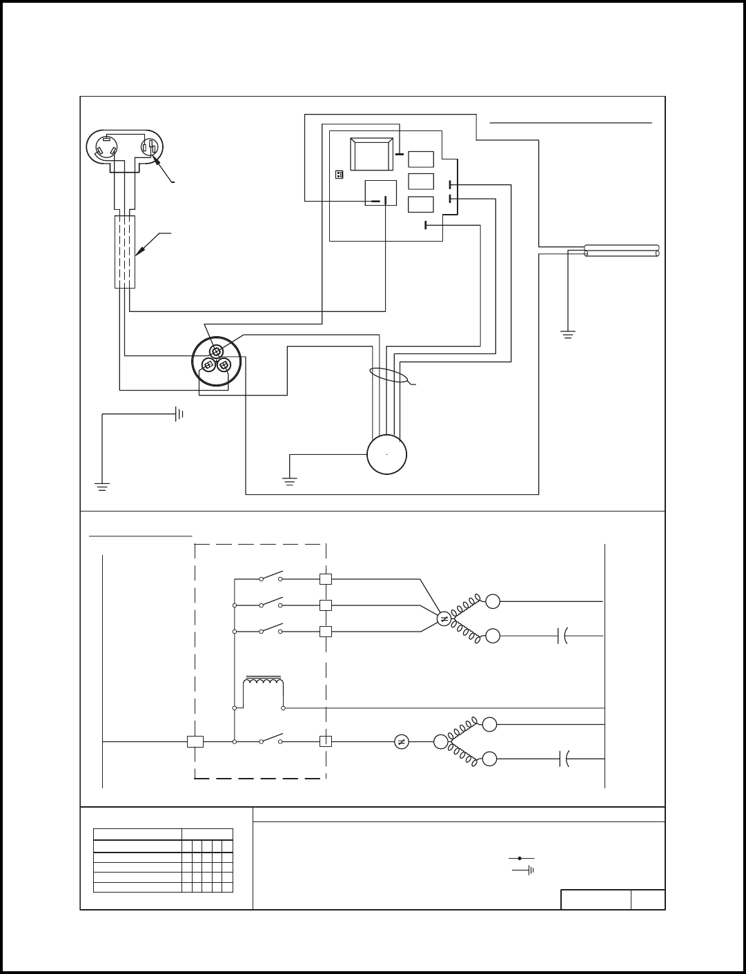
50
MODELS
XQ05J10-B, XQ06J10-A, XQ06J10-B, XQ08J10-1, XQ08J10-A, XQ08J10A-A
ELECTRONIC CONTROL
BLACK
TO CAPACITOR
CAPACITOR
BRACKET
RED
BLUE
GREEN
TO CHASSIS
c
FAN
HERM
BROWN
WHITE
WHITE
GREEN/YELLOW
MOTOR MOUNT
TO INNERWALL/
RIBBED CONDUCTOR
RELAY
RELAY
COM NO
BLUE
BLACK
RED
RELAY
TRANSFORMER
SMOOTH CONDUCTOR
GREEN OR
SUPPLY CORD
MOTOR WIRE
HARNESS
BLACK
RED
BLUE
MOTOR
FAN
TO CAPACITOR
BRACKET
L1
1
2
3
SWITCH LOGIC
ELECTRONIC CONTROL
NO
5
COM
PART NO. REV.
- COMBINATION TERMINAL
(115 V)
OVLD
NEUTRAL
CAP
MTR FAN C
L E G E N D
OVLD
- CAPACITOR
- FAN MOTOR
- OVERLOAD PROTECTOR
- COMPRESSOR
CAP
COMPR
OVLD
MTR
CAP
COMPR HERM C
- GROUND LEAD
619-142-14 03
GREEN/YELLOW
OR BROWN
OR BLUE
GREEN OR
BLACK
BLUE
RED
COMPRESSOR
COMPRESSOR
WIRE HARNESS
COMPRESSOR
TERMINAL
ORIENTATION
MAY VARY.
REFER TO
OVERLOAD
PROTECTOR
COMPRESSOR
MARKINGS ON
LOW
MEDIUM
HIGH
WHITE
BLACK
WIRING DIAGRAM
SCHEMATIC
X = CLOSED
O = OPEN
SWITCH POSITION
MED COOL
LOW COOL
HI COOL
OFF 32154
CIRCUIT
OO OX OO
OO
XO OO OO
XO
O
X
X
X
MEDIUM
HIGH
LOW
R
S
C
R
S
S
C
R
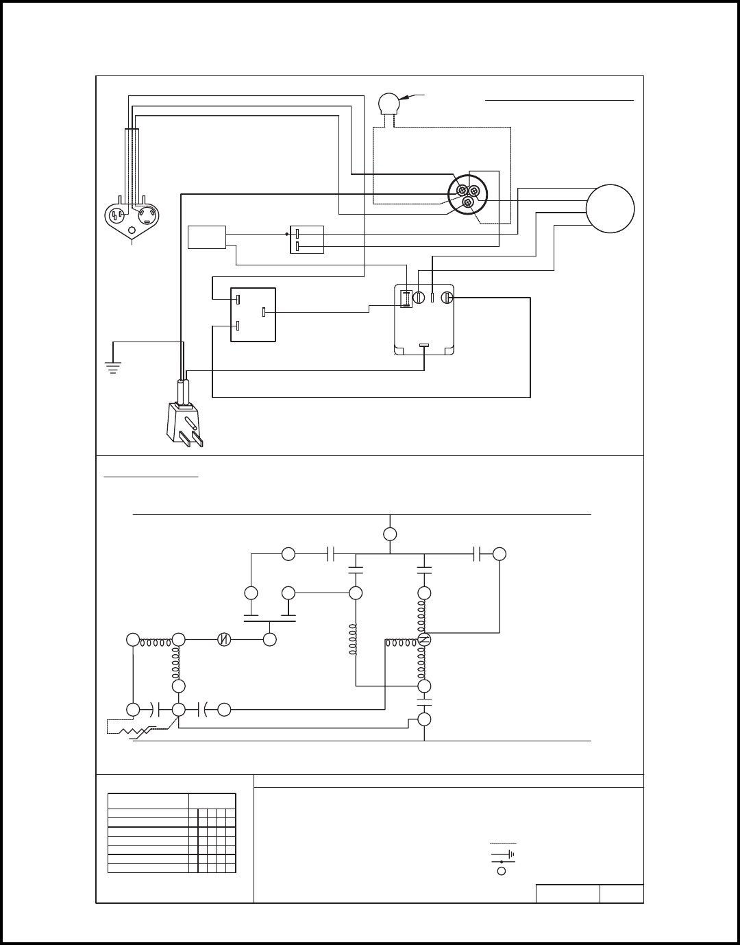
51
MODEL
YQ06J10B-A
PART NO. REV.
617-581-11
- COMBINATION TERMINAL
L E G E N D
- GROUND LEAD
- PLASTIC INSULATOR
- CAPACITOR
- COMPRESSOR
- INDOOR THERMOSTAT
- SYSTEM SWITCH
- FAN MOTOR
- OVERLOAD PROTECTOR
SYS SW
OVLD
IDT
COMPR
MTR
CAP
X = CLOSED
O = OPEN
SWITCH LOGIC
WHITE
TO GND
SCREW
SMOOTH (OR BROWN) CONDUCTOR
GREEN
BLACK
BLUE
BLACK
BLUE
BLACK
BLUE
RED
BLACK
RED
RED
WHITE
BLUE
RED
BLUE
HERM
C
FAN
RED
BLACK
RED
BROWN
WHITE
SOLENOID
SYSTEM SWITCH
LINE
LINE
COMPRESSOR
RUN CAPACITOR
C' OVLD.
THERMOSTAT
DEFROST CONTROL T/STAT.
FAN MOTOR
FAN OVERLOAD
HIGH
LOW
PTCR (OPTIONAL)
- OPTIONAL FACTORY WIRING
00
PTCR - START ASSIST DEVICE
PTCR
(OPTIONAL)
BLACK
BLACK
(HARNESS, COMPR. MOLDED)
COMPRESSOR
BLUE
RED
BLACK
SOLENOID
CAPACITOR
FAN MOTOR
SYSTEM SWITCH
THERMOSTAT
DEFROST CONTROL
SUPPLY CORD
RIBBED (OR BLUE) CONDUCTOR
LO-HEAT
13245
OOOOO
CIRCUIT
OFF
LO-COOL
HI-COOL
HI-FAN
SWITCH POSITION
SCHEMATIC
WIRING DIAGRAM
3
21
1
2
4
C
1 2 3
1
C
2
2
1
C
HF
C
S
3
3142
1
HI-HEAT XX
OOO
X
XX
XX
XX
O
OO
OOOO
OO
OO
O
O
C
S
R
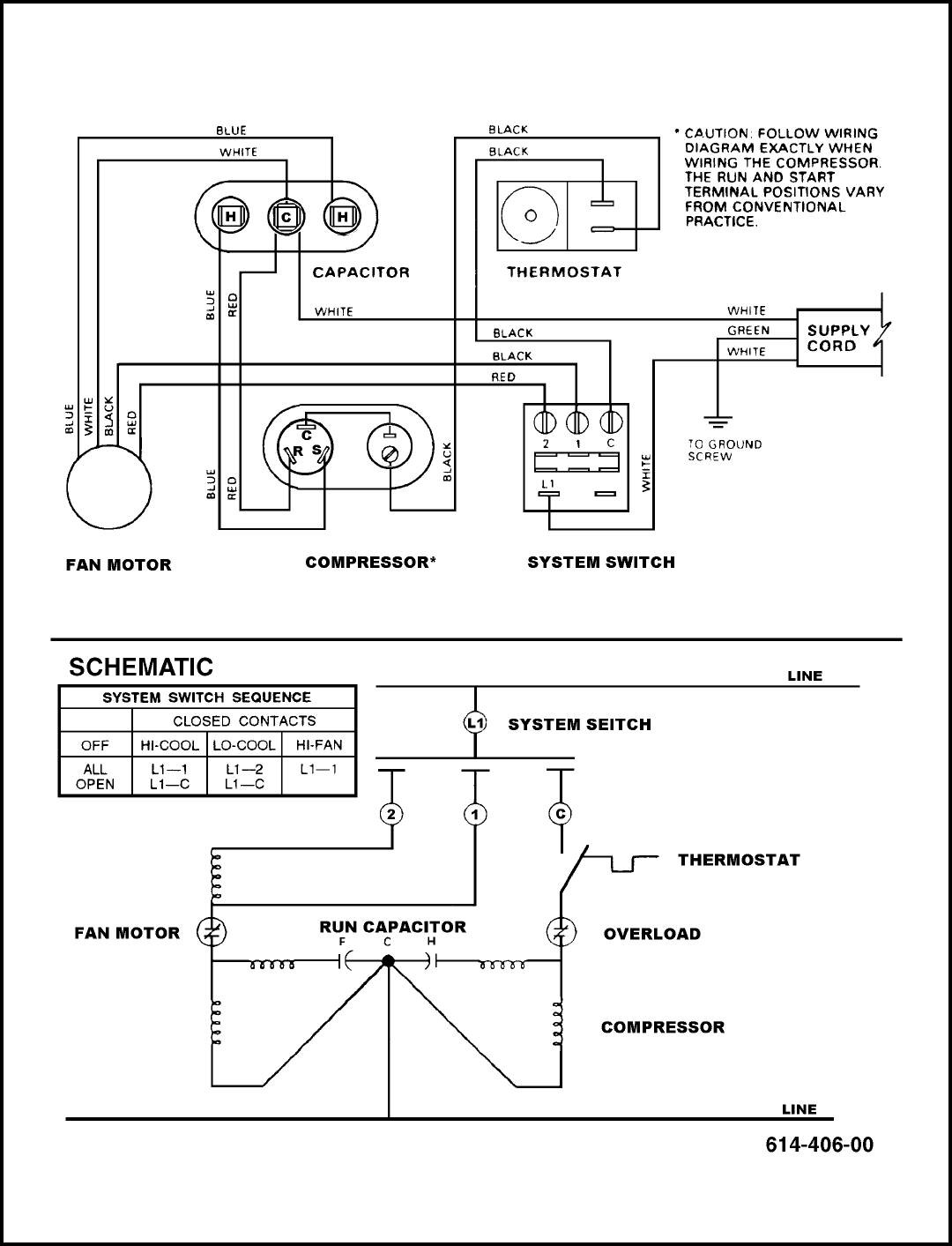
52
MODEL: SC06H10D
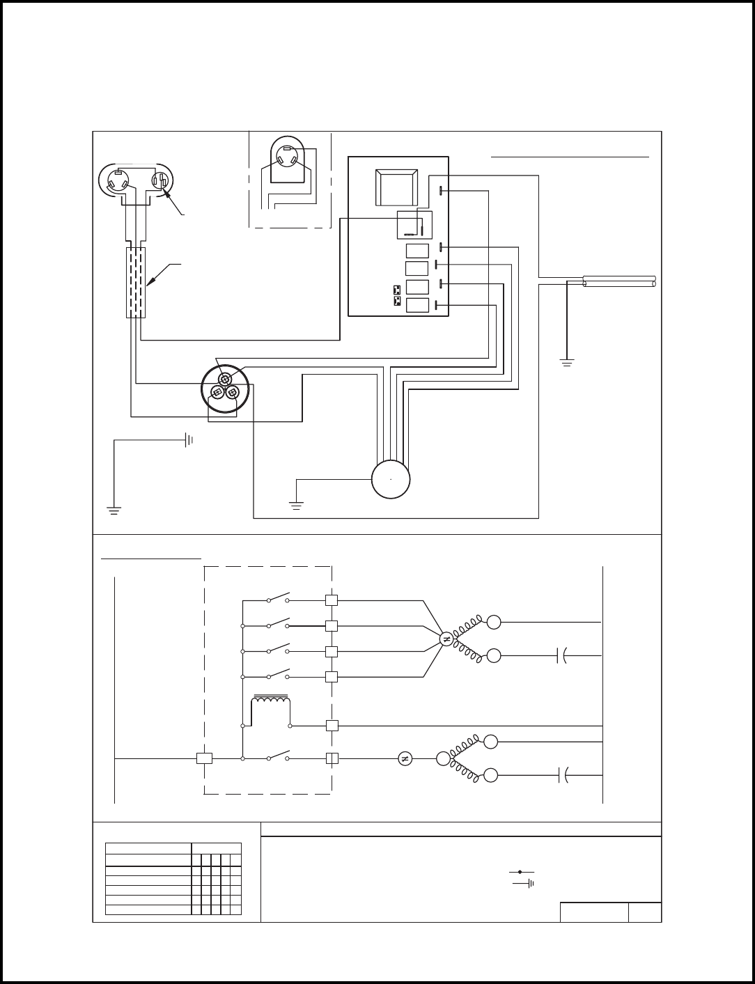
53
MODELS
SS08J10R-B, SS08J10R-A, SS09J10C-A, SS10J10AR-A,
SS12J10AR-B, SS14J10R-A, SS12J30D-A, SS16J30A-A,
SS18J30R-A, SM20J30-A, SM24J30-A
DEFROST
SENSOR
SENSOR
ROOM
TO CHASSIS
BLUE
RED
BRACKET
TO CAPACITOR
GREEN
CAPACITOR
FAN
c
HERM
BRACKET
TO CAPACITOR
GREEN/YELLOW
GREEN OR
RIBBED CONDUCTOR
ELECTRONIC CONTROL
BLACK
OR BROWN
SMOOTH CONDUCTOR
RED
ORANGE
BLACK
WHITE
BLUE
BLACK
ORANGE
WHITE
WHITE
BROWN RED
TO INNERWALL/
GREEN/YELLOW
GREEN OR
MOTOR MOUNT
MOTOR
FAN
OR BLUE
SUPPLY CORD
ELECTRONIC CONTROL
L1
F4
F3
F2
F1
SWITCH LOGIC
NO
5
REV.PART NO.
- GROUND LEAD
NEUTRAL
- COMBINATION TERMINAL
OVLD MTR
CAP
FAN C
- COMPRESSOR
- OVERLOAD PROTECTOR
L E G E N D
COM
OVLD
MTR
OVLD
COMPR
CAP - CAPACITOR
- FAN MOTOR
COMPR
HERM
CAP
C
(230/208)
L2
(115 V)
619-405-06 01
NO
RELAY
RELAY
RELAY
RELAY
COM
TRANSFORMER
BLUE
L1
BLACK
BLUE
RED
COMPRESSOR
S
R
C
COMPRESSOR
WIRE HARNESS
COMPRESSOR
TERMINAL
ORIENTATION
MAY VARY.
REFER TO
OVERLOAD
PROTECTOR
COMPRESSOR
MARKINGS ON
COMPRESSOR
ALTERNATE
RED
BLACK
BLUE
C
S
R
WIRING DIAGRAM
SLEEP OO XOX
SCHEMATIC
LOW COOL
MED COOL
SWITCH POSITION
HI COOL
OFF
X
O
O
O
CIRCUIT
3
O = OPEN
X = CLOSED
12
O
XO
O
O
OX
O
45
X
OO
O
X
XO
O
MEDIUM
HIGH
SLEEP
LOW
R
S
C
R
S
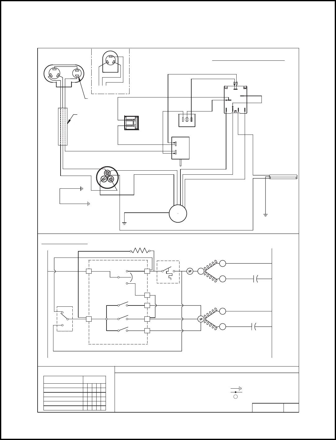
54
MODELS
SL28J30B-A, SL35J30-A, SL35J30-B
BROWN
WHITE
TO INNERWALL/
MOTOR MOUNT
MOLDED
COMPRESSOR
HARNESS,
COMPRESSOR
OVERLOAD
COMPRESSOR
ALTERNATE
BLUE
R
S
C
RED
BLACK
PROTECTOR
BLUE
ANTICIPATOR
RESISTOR
TO CHASSIS
RED
TO CAPACITOR
BLUE
BRACKET
GREEN
CAPACITOR
FAN
c
HERM
BLACK
GREEN/YELLOW
WIRING DIAGRAM
TO CAPACITOR
SUPPLY CORD
SMOOTH CONDUCTOR
BLUE
SYSTEM SWITCH
PURPLE
RED
ROCKER SWITCH (GE)
RED
GREY
BROWN
MS
BLUE
C
2
BLUE
ORANGE
BLACK
L
M
HL1
THERMOSTAT
2
1
BLACK
ORANGE
BLUE
BLUE
MOTOR
FAN
GREEN/YELLOW
OR BROWN
RIBBED CONDUCTOR
OR BLUE
BRACKET
MS M
SCHEMATIC
L1
MS
NO
1
2
L1 1
AR
C
2
2
3H
YES
3
SWITCH POSITION
SWITCH LOGIC
LOW COOL
HI COOL
MED COOL
OFF
SYS SW
4
5L
13245
X = CLOSED
0 = OPEN
CIRCUIT
XOOO
OO OO
XO
XO XO OX
X
O
O
O
FAN ONLY OX OOO
PART NO. REV.
- COMBINATION TERMINAL
MTR
COMPR
IDT
21
OVLD
C
MEDIUM
HIGH
OVLD
R
L2
CAP
SHERM
R
C
L E G E N D
- MONEY SAVER/ROCKER SWITCH
LOW
- COMPRESSOR
- INDOOR THERMOSTAT
- SYSTEM SWITCH
- ANTICIPATOR RESISTOR
- FAN MOTOR
- OVERLOAD PROTECTOR
- CAPACITOR
CAP
MS
AR
SYS SW
OVLD
COMPR
MTR
IDT
CAP
SFAN C
- GROUND LEAD
- PLASTIC INSULATOR
619-405-01 00
R
"F"
S
C
"F" "F"
ORIENTATION MAY VARY. REFER
COMPRESSOR TERMINAL
TO MARKING ON COMPRESSOR.
BLACK OR WHITE
GREEN OR
GREEN OR
3
2
1
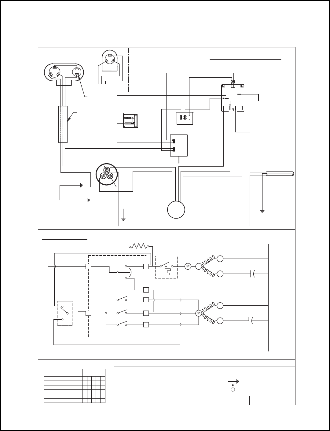
55
MODELS
KS10E10-A, KS10J10-B, KS12E10-A, KS12J10B-A, KS15J10-A,
KS12J30B-A, KS18J30-A, KM20J30-A, KM24J30-A
BROWN
WHITE
TO INNERWALL/
MOTOR MOUNT
MOLDED
COMPRESSOR
HARNESS,
COMPRESSOR
OVERLOAD
COMPRESSOR
ALTERNATE
BLUE
R
S
C
RED
BLACK
PROTECTOR
BLUE
ANTICIPATOR
RESISTOR
TO CHASSIS
RED
TO CAPACITOR
BLUE
BRACKET
GREEN
CAPACITOR
FAN
c
HERM
BLACK
GREEN/YELLOW
WIRING DIAGRAM
TO CAPACITOR
SUPPLY CORD
SMOOTH CONDUCTOR
BLUE
SYSTEM SWITCH
PURPLE
RED
ROCKER SWITCH (GE)
RED
GREY
BROWN
MS
BLUE
C
2
BLUE
ORANGE
BLACK
L
M
HL1
THERMOSTAT
2
1
BLACK
ORANGE
BLUE
BLUE
MOTOR
FAN
GREEN/YELLOW
OR BROWN
RIBBED CONDUCTOR
OR BLUE
BRACKET
MS M
SCHEMATIC
L1
MS
NO
1
2
L1 1
AR
C
2
2
3H
YES
3
SWITCH POSITION
SWITCH LOGIC
LOW COOL
HI COOL
MED COOL
OFF
SYS SW
4
5L
13245
X = CLOSED
0 = OPEN
CIRCUIT
XOOO
OO OO
XO
XO XO OX
X
O
O
O
FAN ONLY OX OOO PART NO. REV.
- COMBINATION TERMINAL
MTR
COMPR
IDT
21
OVLD
C
MEDIUM
HIGH
OVLD
R
L2
CAP
S
HERM
R
C
L E G E N D
- MONEY SAVER/ROCKER SWITCH
LOW
- COMPRESSOR
- INDOOR THERMOSTAT
- SYSTEM SWITCH
- ANTICIPATOR RESISTOR
- FAN MOTOR
- OVERLOAD PROTECTOR
- CAPACITOR
CAP
MS
AR
SYS SW
OVLD
COMPR
MTR
IDT
CAP
S
FAN C
- GROUND LEAD
- PLASTIC INSULATOR
619-405-01 00
R
"F"
S
C
"F" "F"
ORIENTATION MAY VARY. REFER
COMPRESSOR TERMINAL
TO MARKING ON COMPRESSOR.
BLACK OR WHITE
GREEN OR
GREEN OR
3
2
1
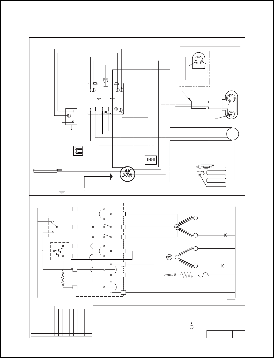
56
MODELS
ES12J33B-A, ES16J33A-A, EM18J34B-A, EL25J35-A, EL35J35-B, EK18J34A
HEATER
BRACKET
TO CAPACITOR
BLACK OR WHITE
M
ORANGE
BLACK
YELLOW
YELLOW
BLUE
RED
THERMOSTAT
YELLOW
RED
BLUE
3
L1
42
C2
L
TO CAPACITOR
CORD
SUPPLY
SMOOTH CONDUCTOR
OR BROWN
12
WHITE
PURPLE
BLUE
ORANGE
BLUE
OR BLUE
ANTICIPATOR
RESISTOR
RIBBED CONDUCTOR
GREEN OR
YELLOW
GREEN/
GREEN
WIRING DIAGRAM
PROTECTOR
BLACK
RED
BLUE
GRAY
WHITE
BLUE
RED
BROWN
SYSTEM SWITCH
BLUE
5
MS
3
1
HAR
C
BROWN
ORANGE
BLACK
S
R
C
RED
BLUE
ALTERNATE
BLACK
COMPRESSOR
WIRE HARNESS
BLACK
PINK
BLACK
WHITE
PURPLE
GRAY
CAPACITOR
ROCKER SWITCH
PINK
c
FAN
RED
RED
BROWN
BLUE
HERM
BLUE
OVERLOAD
BLACK
WHITE
ORANGE
BROWN
RED
ORANGE
MAY VARY.
COMPRESSOR
TERMINAL
ORIENTATION
REFER TO
COMPRESSOR
MARKINGS ON
S
COMPRESSOR
R
C
TO INNERWALL/
FAN
MOTOR
MOTOR MOUNT
GREEN OR
TO CHASSIS
O O O X O X O X O X
LOW HEAT
BRACKET
SCHEMATIC
L1
2
L1
MS
1NO
1
3
MS
3YES
2
IDT 3
1
MEDIUM HEAT
HIGH COOL
MEDIUM COOL
SWITCH POSITION
SWITCH LOGIC
OFF
HIGH HEAT
LOW COOL
AR
C2
AR
SYS SW
CIRCUIT
X = CLOSED
0 = OPEN
1 2 3 4 5 6 7 8 9 10
O O O O O O O O O O
O X O O O X O X O X
O O X O O X O X O X
O O X O X O X O X O
O X O O X O X O X O
O O O X X O X O X O
FAN ONLY X O O O O O O O O O
PART NO. REV.
- GROUND LEAD
- COMBINATION TERMINAL
- PLASTIC INSULATOR
- HEATER LIMIT
- THERMAL FUSE
HERM
HIGH
LOW
MEDIUM
1
2
M
3
4
H
L
5
6C
OVLD R
C
MTR
S
COMPR
R
- OVERLOAD PROTECTOR
- INDOOR THERMOSTAT
L E G E N D
- MONEY SAVER/ROCKER SWITCH
- ANTICIPATOR RESISTOR
7
8
2
4
9
10 5
- SYSTEM SWITCH
- COMPRESSOR
- FAN MOTOR
- CAPACITOR
CAP
MS
AR
OVLD
COMPR
MTR
SYS SW
IDT
HTR
HL
OVLD
TF
S
TF
HTR
HL - HEATER
L2
C
FAN
CAP
CAP
C
619-405-02 00
3
2
1
GREEN/YELLOW
(GE)
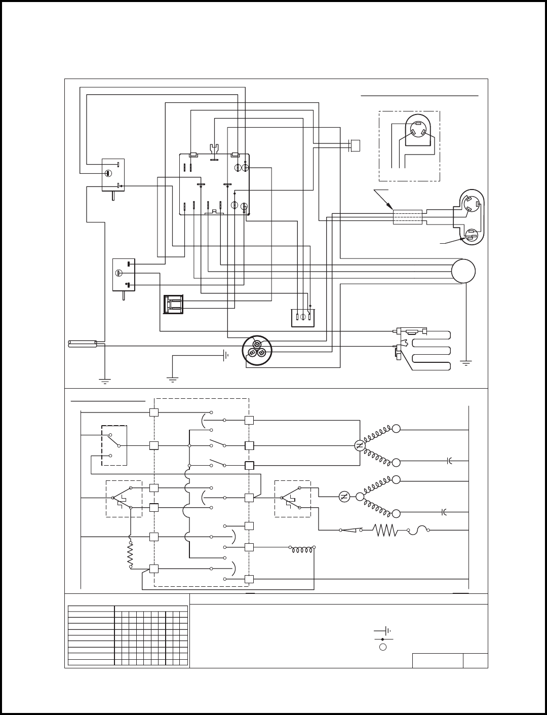
57
MODELS
YS12J33-A, YM18J34B-A, YL24J35C-A
HEATER
PURPLE
CAPACITOR
ROCKER SWITCH
YELLOW
BLUE
RED
PINK
BLACK
PURPLE
BLUE
BLACK
WHITE
ORANGE
BLACK
YELLOW
BLUE
RED
THERMOSTAT
12
3
BLACK
BLACK
BROWN
WHITE
BLUE
RED
WHITE
THERMOSTAT
ORANGE
3
DEFROST
12
CORD
SUPPLY
BLACK
BLACK
BLUE
ANTICIPATOR
RESISTOR
PINK
FAN
MOTOR
SYSTEM SWITCH
BLUE
BLUE
GRAY
VALVE ASY
REVERSING
RED
c
BROWN
HERM
BLUE
RED
BLUE
BLACK
WHITE
ORANGE
BROWN
FAN
ORANGE
RED
5
C
4
2
L
M
H
L1
3
MS
YES2
1NO
IDT
23
1
MS
3
L1
1
2
3
1
4
5
6
1 2 3 4 5 6 7 8 9 10
O O O O O O O O O O
CIRCUIT
O O O X O X O X O X
O X O O O X O X O X
O O X O O X O X O X
O O X O X O X O X O
O X O O X O X O X O
O O O X X O X O X O
AR
SWITCH LOGIC
SWITCH POSITION
MEDIUM COOL
LOW COOL
HIGH COOL
HIGH HEAT
LOW HEAT
MEDIUM HEAT
OFF
SYSTEM SWITCH
C2
AR
9
7
8
10
X = CLOSED
0 = OPEN
X O O O O O O O O O
FAN ONLY PART NO. REV.
- COMBINATION TERMINAL
L2
MEDIUM
HIGH
OVLD
1
3
2
ODT
LOW
OVLD
MTR
R
COMPR
R
S
C
S
FAN C
CAP
HERM C
L E G E N D
RV HL
- CAPACITOR
- FAN MOTOR
- OVERLOAD
- INDOOR THERMOSTAT
- MONEY SAVER
- ANTICIPATOR RESISTOR
- REVERSING VALVE
- COMPRESSOR
AR
MS
CAP
COMPR
OVLD
MTR
RV
IDT
HTR TF
CAP
- HEATER LIMIT
- HEATER
- GROUND LEAD
- PLASTIC INSULATOR
- THERMAL FUSE
TF
HTR
HL
- OUTDOOR THERMOSTAT
ODT 619-405-04
ALTERNATE
COMPRESSOR
(GE)
01
TO CAPACITOR
L
2
C2
HAR M
L1 4
MS
5
3
1
C
RIBBED CONDUCTOR OR BLUE
SMOOTH CONDUCTOR OR BROWN
GREEN OR
GREEN
TO CAPACITOR
BRACKET
WIRING DIAGRAM
GRAY BROWN
BRACKET
SCHEMATIC
TO CHASSIS
GREEN/
YELLOW
BLACK OR WHITE
OVERLOAD
PROTECTOR
COMPRESSOR
WIRE HARNESS
C
BLACK
RED
BLUE
R
S
RED
BLACK
BLUE
S
C
R
MAY VARY.
COMPRESSOR
ORIENTATION
COMPRESSOR
MARKINGS ON
REFER TO
TERMINAL
GREEN OR
GREEN/YELLOW
TO INNERWALL/
MOTOR MOUNT
3
2
1
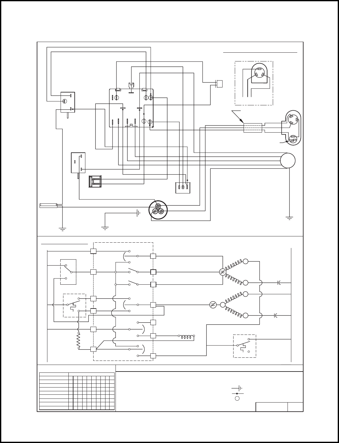
58
MODEL
YS09J10B-A
PART NO. REV.
619-142-17
- COMBINATION TERMINAL
L E G E N D
- GROUND LEAD
- PLASTIC INSULATOR
- CAPACITOR
- FAN MOTOR
- OVERLOAD PROTECTOR
- INDOOR THERMOSTAT
- MONEY SAVER
- ANTICIPATOR RESISTOR
- REVERSING VALVE
- COMPRESSOR
COMPR
RV
OVLD
IDT
MTR
AR
MS
CAP
PURPLE
CAPACITOR
MOTOR
GRAY
FAN
ORANGE
BROWN
BLACK
BLUE
WHITE
ROCKER SWITCH
BROWN
BLUE
HERM
RED
c
GRAY BROWN
SWITCH
BLUE
1
BLACK OR WHITE
ANTICIPATOR
FAN
RED
RESISTOR
BLUE
PINK
WHITE
PURPLE
BLUE
BLACK
WHITE
ORANGE
2
BLUE
THERMOSTAT
BLUE
RED
3
BROWN
RED
YELLOW
RED
BLUE
5
C
4
2
L
M
H
IDT
L1
7
AR
AR
C2
SYSTEM SWITCH
10
9
8
2
1
YES
1
33
1
3
NO2
MS
MS
L1
3
5
6
4
2
1
LOW
HIGH
MEDIUM
C
OVLD
OVLD
C
FAN
HERM
COMPR
C
CAP
MTR
R
SWITCH LOGIC
SWITCH POSITION
FAN ONLY
MEDIUM COOL
OFF
LOW COOL
HIGH COOL
HIGH HEAT
LOW HEAT
MEDIUM HEAT
1 2 3 4 5 6 7 8 9 10
O O O O O O O O O O
X O O O O O O O O O
X = CLOSED
0 = OPEN
CIRCUIT
O O O X O X O X O X
O X O O O X O X O X
O O X O O X O X O X
O O X O X O X O X O
O X O O X O X O X O
O O O X X O X O X O
VALVE
REVERSING
WHITE
BLACK
CORD
SUPPLY
YELLOW
S
S
R
- OUTDOOR THERMOSTAT
ODT
RV
L2
01
RED
BLUE
ALTERNATE
COMPRESSOR
(GE)
BLUE
SYSTEM
BLACK
ODT
3
2
1
THERMOSTAT
1
3
2PINK
DEFROST
WHITE
TO CHASSIS
WIRING DIAGRAM
GREEN
TO CAPACITOR
BRACKET
L
5L1
H
CAR M
3MS 4
C2
2
SCHEMATIC
1
RIBBED CONDUCTOR OR BLUE
SMOOTH CONDUCTOR OR BROWN
YELLOW
GREEN/
GREEN OR
TO CAPACITOR
BRACKET
BLUE
BLACK
RED
COMPRESSOR
WIRE HARNESS
OVERLOAD
PROTECTOR
C
BLACK
BLUE
RED
R
S
COMPRESSOR
R
S
C
TERMINAL
MAY VARY.
ORIENTATION
MARKINGS ON
REFER TO
COMPRESSOR
MOTOR MOUNT
TO INNERWALL/
GREEN/YELLOW
GREEN OR
2
3
1
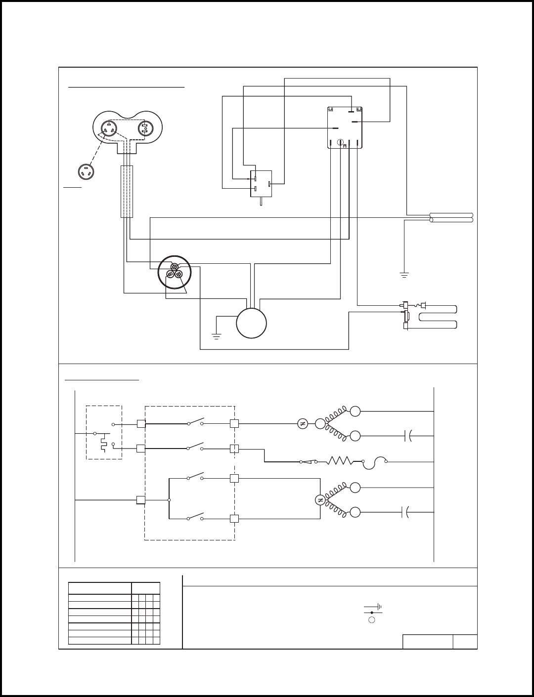
59
MODELS
EQ08J11-A, EQ08J11-B
HARNESS, COMPR.
COMPRESSOR
CAPACITOR
BLUE
RED
HERM
C
FAN
BLACK
BROWN
WHITE
GREEN
RED
BLACK
2
L1
BLUE
C
MS
L
SMOOTH (OR BROWN)
BLUE
SWITCH
H
BLUE
CONDUCTOR
SYSTEM
SUPPLY CORD
BLACK
THERMOSTAT
2
1
RED
FAN
MOTOR
BRACKET
TO CAPACITOR
GREEN
MS
L1
L1 1C
22
3H
SWITCH LOGIC
SYS SW
4L
X = CLOSED
0 = OPEN
PART NO. REV.
- COMBINATION TERMINAL
MTR
COMPR
IDT
OVLD
OVLD
L2
CAP
HERM C
L E G E N D
- COMPRESSOR
- INDOOR THERMOSTAT
- SYSTEM SWITCH
- FAN MOTOR
- OVERLOAD PROTECTOR
- CAPACITOR
CAP
SYS SW
OVLD
COMPR
MTR
IDT
CAP
FAN C
- GROUND LEAD
- PLASTIC INSULATOR
617-581-12 01
NOTE:
OPTIONAL
CONFIGURATION
HTR
HL TF
3
HEATER
ORANGE
RED
RIBBED CONDUCTOR
L2
L2
YELLOW
RED
ORANGE
BLACK
- PRE-INSULATED CONDUCTOR
- HEATER
HTR
- HEATER LIMIT
HL - THERMAL FUSE
TF
RED
WIRING DIAGRAM
SCHEMATIC
SWITCH POSITION
LOW COOL
HI COOL
LOW HEAT
OFF 1324
CIRCUIT
OO O
OO OO
XO
XOXX
XO
O
HI HEAT OXO
2
1C
R
S
R
S
C
"F""F"
S
"F"
S
C
R
FAN
X
XXOO
1
2
3
4
5
6
3
**
*
*
*
*
**
*
R
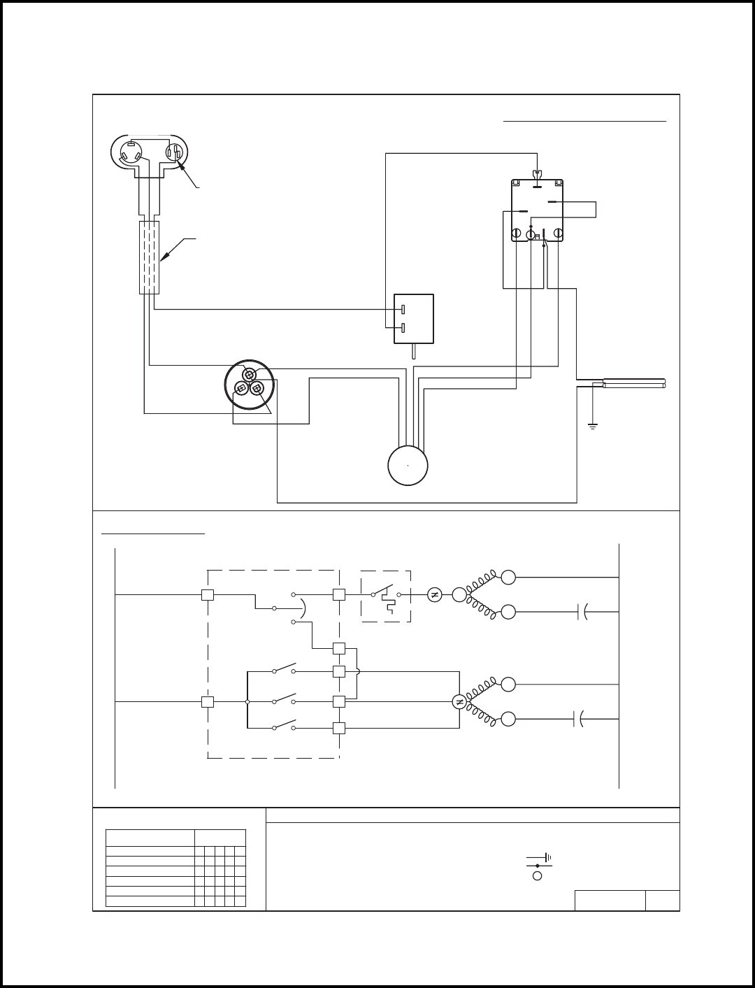
60
MODELS
WS07A10E-B, WS07A10E-C, WS10A10-A, WS12A10E-A,
WS09A30E-B, WS12A30E-A, WS15A30-A
WHITE (OR YELL0W)
BROWN
BLACK
BLUE
RED CAPACITOR
FAN
c
HERM
TO GROUNDING
SUPPLY CORD
SMOOTH CONDUCTOR
BROWN
SYSTEM SWITCH
BLUE
MS
PURPLE
C
2
BLACK
PURPLE
L
M
HL1
RED
THERMOSTAT
1
2
PURPLE
BLACK
RED
MOTOR
FAN
GREEN
RIBBED CONDUCTOR
SCREW
M
MS
L1
L1 1C
2
2
3H
SWITCH LOGIC
SYS SW
4
5L
0 = OPEN
X = CLOSED
REV.PART NO.
- COMBINATION TERMINAL
(208/230 V)
(115 V)
MTR
COMPR
IDT
OVLD
OVLD
NEUTRAL
L2
CAP
HERM C
L E G E N D
- OVERLOAD PROTECTOR
- FAN MOTOR
- SYSTEM SWITCH
- INDOOR THERMOSTAT
- COMPRESSOR
- CAPACITOR
CAP
SYS SW
OVLD
MTR
COMPR
IDT
CAP
FAN C
- PLASTIC INSULATOR
- GROUND LEAD
617-581-14 00
WIRING DIAGRAM
SCHEMATIC
SWITCH POSITION
LOW COOL
MED COOL
HI COOL
OFF 54231
CIRCUIT
XOOO
OO OO
XO
XO XO OX
X
O
O
O
FAN ONLY OX OOO
21C
MEDIUM
HIGH
R
S
R
LOW S
RED
BLUE
BLACK
COMPRESSOR
C
S
R
OVERLOAD
PROTECTOR
COMPRESSOR
WIRE HARNESS
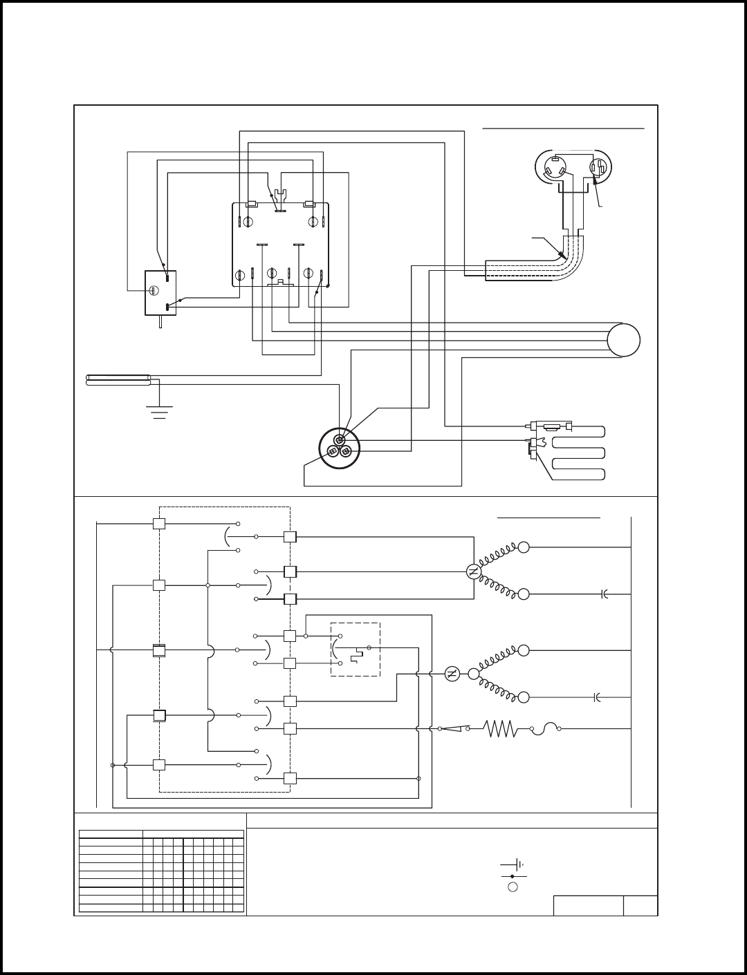
61
MODELS
WE09A33E-B, WE12A33E-A, WE15A33-A
L1 L2
BLUE
PURPLE
WHITE
3
12
PINK
RED
BROWN
SMOOTH CONDUCTOR
RIBBED CONDUCTOR
THERMOSTAT
CORD
SUPPLY YELLOW
CAPACITOR
FAN
MOTOR
BLACK
SYSTEM SWITCH
BLACK
ORANGE
YELLOW
RED
HERM
c
BLUE
YELLOW
PURPLE
RED
BROWN
FAN
HEATER
COMPR
SYS SW
OVLD
L1
MS
C
1
2M
H
L
3
4
7
3
5
1
2
6
1 2 3 4 5 6 7 8 9 10
O O O O O O O O O O
O O O X O X O X O X
O X O O O X O X O X
O O X O O X O X O X
O O X O X O X O X O
O X O O X O X O X O
O O O X X O X O X O
CIRCUIT
C2
AR
SWITCH LOGIC
SWITCH POSITION
MEDIUM COOL
LOW COOL
HIGH COOL
HIGH HEAT
LOW HEAT
MEDIUM HEAT
OFF
8
9
SYS SW
10
4
5
X = CLOSED
0 = OPEN
MS
AR
CAP
MTR
IDT
X O O O O O O O O O
FAN ONLY
PART NO. REV.
- COMBINATION TERMINAL
CAP
OVLD
MEDIUM
HIGH
LOW
1
32
OVLD
C
R
MTR
SFAN
CAP
C
R
COMPR
SHERM C
L E G E N D
HL
- OVERLOAD PROTECTOR
- INDOOR THERMOSTAT
- MONEY SAVER/ROCKER SWITCH
- ANTICIPATOR RESISTOR
- SYSTEM SWITCH
- COMPRESSOR
- CAPACITOR
- FAN MOTOR
HTR TF
- THERMAL FUSE
- HEATER LIMIT
- HEATER
- GROUND LEAD
- PLASTIC INSULATOR
TF
HTR
HL
617-581-15 00
SCHEMATIC
MS
LC2
2
CH
L1
4
M
3
5
1
AR
WIRING DIAGRAM
OVERLOAD
PROTECTOR
COMPRESSOR
WIRE HARNESS
BLACK
RED
BLUE
COMPRESSOR
S
R
C
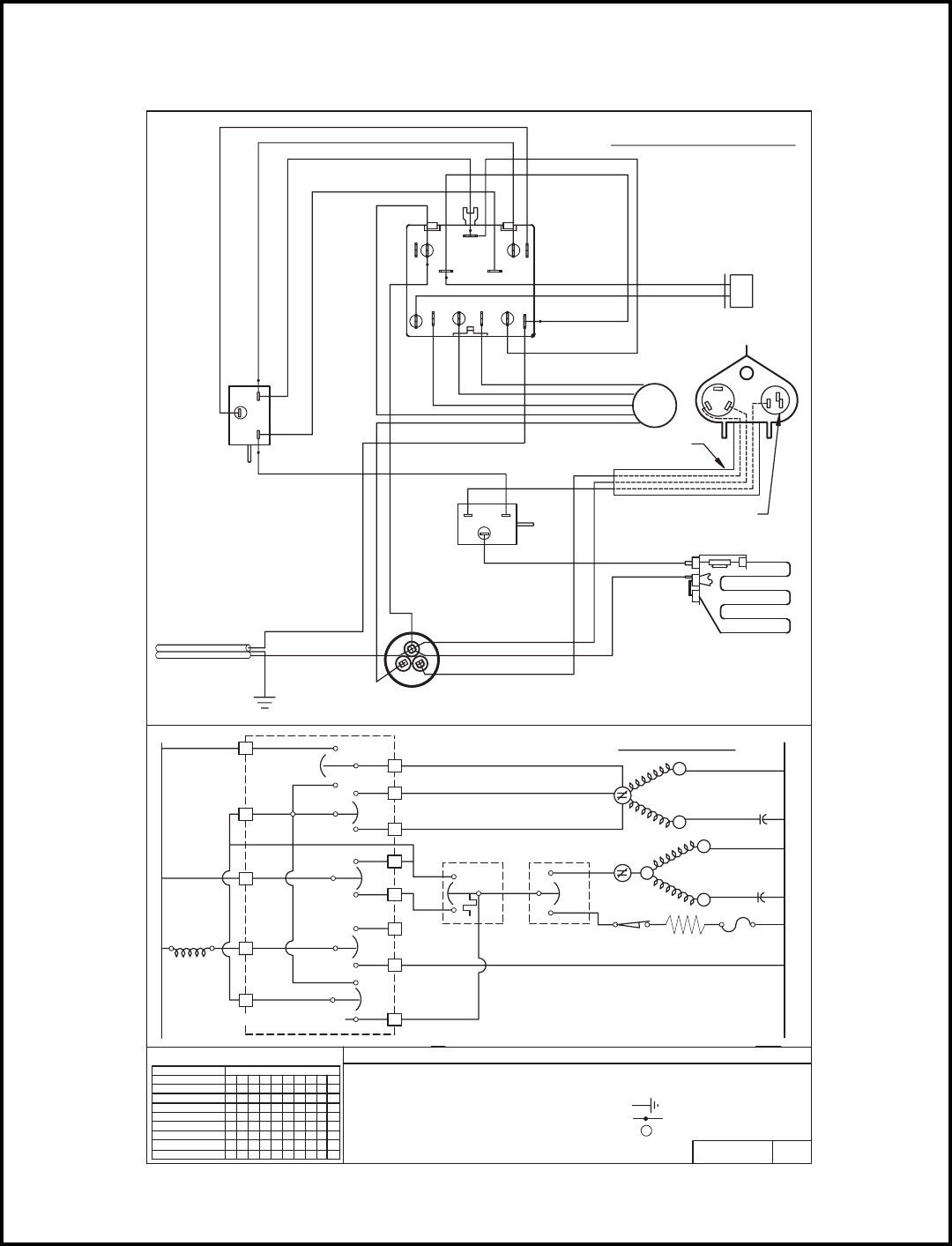
62
MODELS
WY09A33F-A, WY12A33G-A
TO GROUNDING
PART NO. REV.
617-581-02
- OUTDOOR THERMOSTAT
ODT
- COMBINATION TERMINAL
L2
L E G E N D
- HEATER LIMIT
- HEATER
- GROUND LEAD
- PLASTIC INSULATOR
- THERMAL FUSE
TF
HTR
HL
HTR TF
HL
- CAPACITOR
- OVERLOAD PROTECTOR
- INDOOR THERMOSTAT
- MONEY SAVER
- COMPRESSOR
- REVERSING VALVE
- FAN MOTOR
COMPR
OVLD
IDT
RV
MTR
MS
CAP
ODT
OVLD
FAN C
COMPR
HERM
CAP
C
S
CAP
R
C
S
OVLD
MTR
R
3
1
2
LOW
3
2
1
IDT
MEDIUM
HIGH
X O O O O O O O O O
FAN ONLY
2
7
CIRCUIT
O X O O O X O X O X
1 2 3 4 5 6 7 8 9 10
O O O O O O O O O O
O O X O O X O X O X
O O X O X O X O X O
O X O O X O X O X O
O O O X X O X O X O
O O O X O X O X O X
0 = OPEN
X = CLOSED
8
9
5
4
10
MEDIUM COOL
LOW COOL
HIGH COOL
HIGH HEAT
MEDIUM HEAT
LOW HEAT
SWITCH LOGIC
SWITCH POSITION
OFF
AR
C2
RV
4
5
6
1
3
L
3H
M
2
1
MS
C
SCREW
L1
L1
T/STAT
DEFROST
HERM
CAPACITOR
HEATER
RED
BLACK
BLUE
YELLOW
ORANGE
YELLOW
BLUE
RED
ORANGE
1
3
2
FAN MOTOR
BLACK
BLUE
COMPRESSOR
REV VALVE
BROWN
RED
YELLOW
BLACK
PURPLE
BLACK
BLACK
BLUE
SYSTEM SWITCH
BLUE
BLACK
YELLOW
BROWN
RIBBED CONDUCTOR
SMOOTH CONDUCTOR
FAN
c
SUPPLY CORD
BROWN
BLUE
BLACK
YELLOW
WHITE
BLUE
2
THERMOSTAT
3
1
YELLOW
BROWN
BLUE
BLUE
WHITE
03
HARNESS, COMPRESSOR
MOLDED
OVERLOAD,
PROTECTOR
SCHEMATIC
CAR H
5
M
L1
WIRING DIAGRAM
13MS 4
GREEN
C2
L
2
S
R
C

63
Testing The Electronic Control
2001 XQ Boards & QME Boards
Checking Room Temperature:
1. Check the room temperature at the electronic control pad by pressing at the same time the
"FAN SPEED" button and the temperature "UP" button on XQ models.
2. Check the room temperature at the electronic control pad by pressing at the same time the
"FAN SPEED" button and the "WARMER" button on QME models. The indoor temperature
will display for 10 seconds. Indoor temperature can be viewed in all modes, including the TEST
mode. The display can be changed back to SET temperature by pressing any key, except the
ON/OFF button, or after 10 seconds has elapsed.
Activating Test Mode: Activate test mode by pressing at the same time the "MODE" button and
the temperature "DOWN" button on XQ models. LEDs for Hour, Start, and Stop will blink 1
bps while Test Mode is active. Activate test mode by pressing at the same time the "MONEY
SAVER" button and the "FILTER ALERT" button on QME models. LED for the Filter Alert will
blink 1 bps while Test Mode is active.
Test Mode has duration of 90 minutes. Test Mode can be activated under any conditions,
including Off. Test Mode is cancelled by pressing the On/Off button, unplugging the unit, or
when the 90 minutes is timed out. All settings revert to the factory default settings of Cool, 75
degrees F, Timer and Set Hour features are nonfunctional.
Test Mode overrides the three-minute lockout, all delays for compressor and fan motor start /
speed change, and no delay when switching modes.
Test Mode default settings are ON, Money
Saver, 60 degrees F, and High fan speed
.
Activating Error Code Mode: (Submode of Test Mode) Unit has to be in Test Mode to enter Error
Code Mode
1. Activate Error Code Mode by pressing the "TIMER ON/OFF" button on XQ models. LED for
the "TIMER ON/OFF" will flash 1 bps while Error Code Mode is active. Pressing the "TEMP/
HR + " button will display 00. Consecutive presses will scroll through all error codes logged.
Press the "TEMP/HR - " button to see the reverse order of all error codes logged. When the
end of logged error codes is reached the temperature set point will appear.
Activate Error Code Mode by pressing at the same time the "A/C START" button and the "ON/
OFF" button on QME models. LED for the "TIMER ON/OFF" will flash 1 bps while Error Code
Mode is active. Pressing the "WARMER" button will display 00. Consecutive presses will scroll
through all error codes logged. Press the "COOLER" button to see the reverse order of all
error codes logged. When the end of logged error codes is reached the temperature set point
will appear.
IMPORTANT
Error Codes are cleared from the log by exiting from Error Code Mode. To exit on XQ models,
press Timer On/Off button. To exit QME models, press A/C Start and On/Off buttons. Or unplug
unit to exit Error Code Mode. Plug unit in after 5 seconds to resume normal operation of unit.

RACServMn (7-03)
FRIEDRICH AIR CONDITIONING CO.
Post Office Box 1540 · San Antonio, Texas 78295-1540
4200 N. Pan Am Expressway · San Antonio, Texas 78218-5212
(210) 357-4400 · fax (210) 357-4480
www.friedrich.com
Printed in the U.S.A.
