Frigidaire GLTF1670AS0 User Manual WASHER Manuals And Guides L0410185
FRIGIDAIRE Residential Washers Manual L0410185 FRIGIDAIRE Residential Washers Owner's Manual, FRIGIDAIRE Residential Washers installation guides
User Manual: Frigidaire GLTF1670AS0 GLTF1670AS0 FRIGIDAIRE WASHER - Manuals and Guides View the owners manual for your FRIGIDAIRE WASHER #GLTF1670AS0. Home:Laundry & Garment Care Parts:Frigidaire Parts:Frigidaire WASHER Manual
Open the PDF directly: View PDF ![]() .
.
Page Count: 5
i((
Installation
Instructions
Full Size Tumble Action Washers
Before beginning installation, carefully read these instructions• This will simplify the
installation and ensure the washer is installed correctly and safely. Leave these instructions
near the washer after installation for future reference.
NOTE: The electrical service to the washer must conform with local codes and ordinances
and the latest edition of the National Electrical Code, ANSIINFPA 70 or in Canada, CSA
C22.1 Canadian Electrical Code Part 1. Contents
For your safety the information in
this manual must be followed to minimize the
risk of fire or explosion or to prevent property
damage, personal injury or loss of life.
- Do not store or use gasoline or other
flammable vapors and liquid in the vicinity of
this or any other appliance.
-WHAT TO DO IF YOU SMELL GAS
• Do not try to light any appliance.
• Do not touch any electrical switch; do not
use any phone in your building.
• Clear the room, building or area of all
occupants.
• Immediately call your gas supplier from a
neighbor's phone. Follow the gas suppliers
instructions.
• If you cannot reach your gas supplier, call
the fire department.
Installation and service must be performed by
a qualified installer, service agency or the gas
supplier.
Printed in U.S.A.
SUBJECT PAGE
Pre-lnstallationRequirements 2
ElectricalRequirements 2
GroundingRequirements 2
Water SupplyRequirements 2
Drain Requirements 2
Rough-In Dimensions 3
LocationOf Your Washer 4
Unpacking 4
Installation 5
Replacement Parts 5
PIN 131997600 (0010)
PRE-INSTALLATION REQUIREMENTS
Tools Required for Installation:
1. 1/4 in. nut driver
2. 3/8 in. socket with ratchet.
3, 3/8 in. open end wrench.
4. 7/16 in. socketwith ratchet.
5. 9/16 in. open end wrench.
6. Channel-lock adjustable pliers.
7, Carpenter's level.
ELECTRICAL REQUIREMENTS
CIRCUIT - Individual,properly polarized and grounded
15 amp. branchcircuitfused with 15 amp, time delay
fuse or circuitbreaker•
POWER SUPPLY- 2 wire,withground, 120volt,single
phase, 60 Hz, Alternating Current.
OUTLET RECEPTACLE -Properlygrounded 3-prong
receptacle to be located so the power supply cord is
accessiblewhen the washer is inan installed position.
GROUNDING REQUIREMENTS
Improper connection of the equipment
grounding conductor can result in arisk of electrical
shock. Check with a licensed electrician if you are in
doubt as to whether the appliance is propedy grounded.
1. The washer MUST be grounded. In the event of
malfunctionorbreakdown, groundingwillreduce
the risk of electrical shock by a path of least
resistance for electrical current.
2. Since your washer is equipped with a power
supply cord having an equipment-grounding
conductorand a groundingplug, the plug MUST
be plugged into an appropriate, copper wired
receptacle that is properlyinstalledand grounded
inaccordancewith alllocal codes and ordinances
or inthe absenceof local codes, withthe National
Electrical Codes, ANSI/NFPA 70 (latest edition).
If in doubt, call a licensed electrician. DONOT
cut off or alter the groundingprong onthe power
supply cord. In situations where a two-slot
receptacle is present, it is the owner's
responsibility to have a licensed electrician
replace it witha properly grounded three prong
grounding type receptacle.
WATER SUPPLY REQUIREMENTS
Hot and cold water faucets MUST be installedwithin
42 inches (107 cm) of your washer's water inlet. The
faucets MUST be 3/4 inch (1.9 cm) garden hose type
so inlet hoses can be connected. Water pressure
MUST be between 10 and 120 pounds per square
inch (maximum unbalance pressure, hotvs. cold, 10
psi.) Your water department can advise you of your
water pressure.The hotwater temperatureshouldbe
about 140 degrees F (60 degrees C).
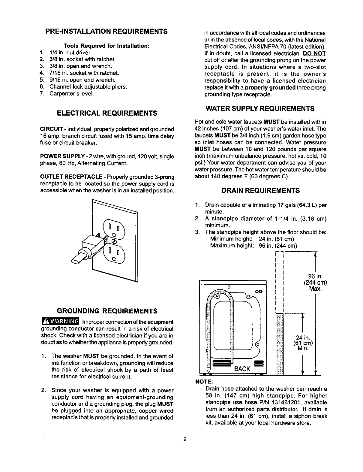
DRAIN REQUIREMENTS
1. Drain capable of eliminating 17 gals (64.3 L) per
minute.
2. Astandpipe diameter of 1-1/4 in. (3.18 cm)
minimum.
3. The standpipeheightabove thefloorshouldbe:
Minimum height: 24 in. (61 cm)
Maximum height: 96 in. (244 cm)
--,9
o
NOTE:
96 in.
(244 cm)
Max.
24 in.
(61 cm)
Min.
Drain hose attached to the washer can reach a
58 in. (147 cm) high standpipe. For higher
standpipe use hose PIN 131461201, available
from an authorized parts distributor. If drain is
less than 24 in. (61 cm), install a siphon break
kit, available at your local hardware store.
17
(43.2) |_24 3/4
2
(5,1) _' -- (62.9)
i
\
m
i
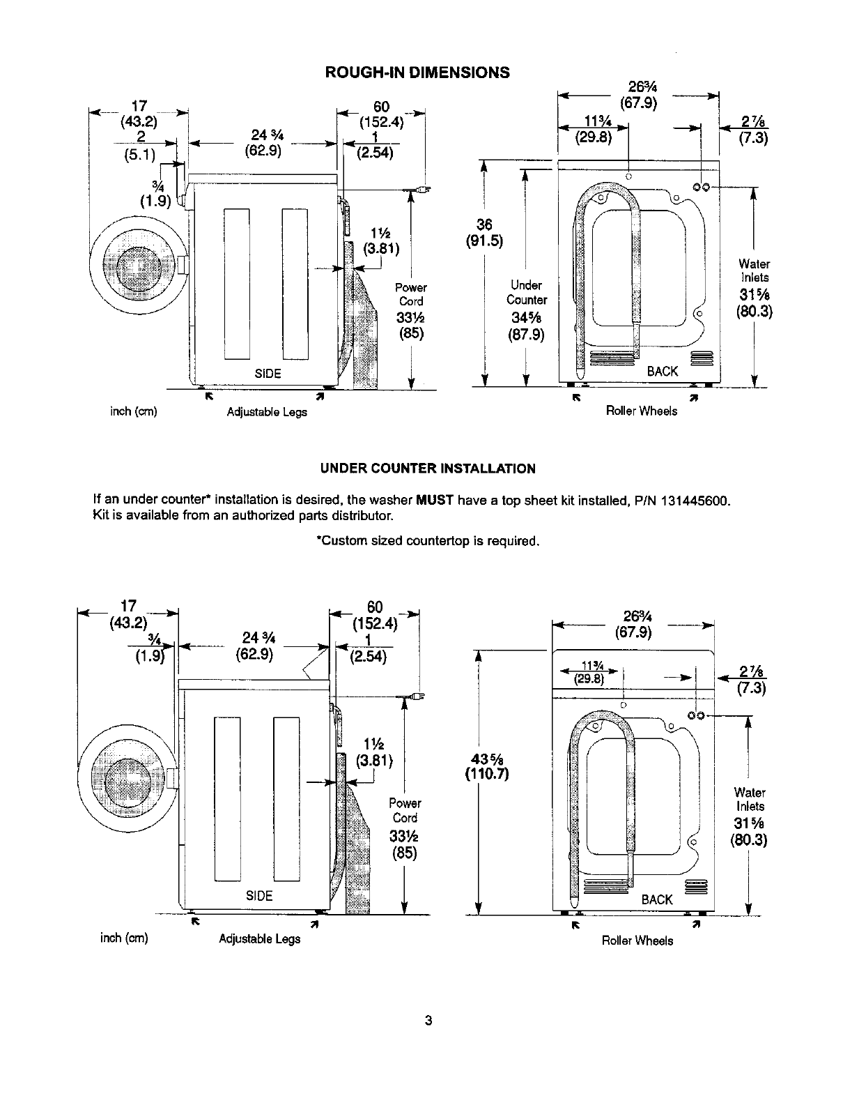
ROUGH-IN DIMENSIONS
SIDE
inch(cm) AdjustableLegs
.< 60 _,
(I52.4)--
(2.54_
(3.81)
'i_ Power
, Cord
331,_
_(65)
I
]
36
(91.5)
I
I
26%
(67.9)
F
Under
Counter
34%
(87.9)
R
2%
(7.3)
I
]
I
o
ii__
Water
_______ ]nlete
31%
(80.3)
BACK 1
L _ mJ
RollerWheels
UNDER COUNTER INSTALLATION
If an under counter* installationis desired, the washer MUST have a top sheet kit installed, PIN 131445600.
Kit is available from an authorized parts distributor.
*Custom sized countertopis required.
(43.2) 24%
(62.9)
]
I
!
m
SIDE
inch (cm) AdjustableLegs
,__ 60 ___
(152.4)
/(2.54)
43%
(110.7)
263.4
<------(67.9)
0
BAc 1
RollerWheels
3
LOCATION OF YOUR WASHER
DO NOT INSTALL YOUR WASHER:
1. In an area exposed to drippingwater or outside
weather conditions. The ambient temperature
should never be below 60 degrees F (15.6
degrees C) for proper washer operation.
2. In an area where it will come in contact with
curtainsor drapes.
3. In an area (garage orgarage-type building)where
gasoline of other flammables are kept or stored
(includingautomobiles).
4. On carpet. Floor MUST be solidwith a maximum
slope of 1/2 in. perfoot (1.27 cm per 30.5 cm). To
ensure vibration or movement does not occur,
reinforcementof the floormay be necessary.
MINIMUM INSTALLATION CLEARANCES
When installed in alcove or closet:
Sides, Rear = 0 in. (0 crn)
Top = 0in. (0 cm) Front Console Model
Top = 15 in. (38.1 cm) Rear Console Model
When installed in closet: Front = 1 in. (2.54 cm)
Closet door ventilationrequired: 2 Iouvered openings
each 60 irf (387 cmZ),3 in. (7.6 cm) from top and bottom
of door.
3. Remove the styrofoam base.
4. Carefully returnthe washer to an upright position
and remove the carton.
5. Carefullymove the washerto within4 feet(122cm)
of the final location.
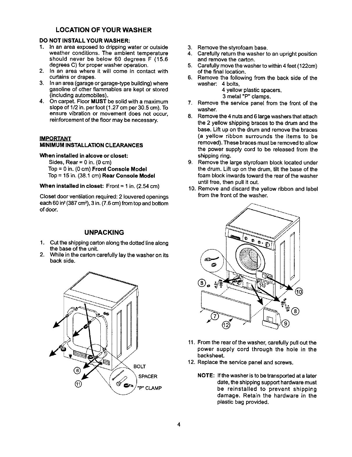
6. Remove the following from the back side of the
washer: 4 bolts,
4 yellow plastic spacers,
3 metal "P" clamps.
7. Remove the service panel from the front of the
washer.
8. Removethe 4 nutsand 6 large washersthat attach
the 2 yellow shipping bracesto the drum and the
base. Liftup on the drum and removethe braces
(a yellow ribbon surrounds the items to be
removed).These braces mustbe removedto allow
the power supply cord to be released from the
shippingring.
9. Remove the large styrofoam block located under
the drum. Liftup on the drum, tilt the base of the
foam block inwardstoward the rear of the washer
untilfree, then pullit out.
10. Remove and discard the yellow ribbonand label
from the front of the washer.
UNPACKING
1. Cut the shippingcartonalongthe dotted line along
the base of the unit.
2. While inthe cartoncarefully lay the washer on its
back side.
(_ ,BOLT
SPACER
(_ "P" CLAMP
11. From the rear of the washer, carefully pull out the
power supply cord through the hole in the
backsheet.
12. Replace the service panel and screws.
NOTE: Ifthe washer is to be transported at a later
date, the shippingsupporthardwaremust
be reinstalled to prevent shipping
damage. Retain the hardware in the
plastic bag provided.
4
INSTALLATION
I.
2.
3,
4.
5.
6.
7.
Run some water from the hot
and cold faucets to flush the
water lines and remove
particles that might clog up
the water valve screens.
Remove the inlet hoses and
rubber washers from the
plastic bag and install the
rubber washers in each end
of the inlet hoses.
(90" elbow end) Carefully
connect theinlet hose marked
"HOT" to theoutside "H"outlet
of the watervalve. Tighten by
hand, then tighten another
2/3 turn with pliers,
Carefully connect the other inlet hose to the inside
"C" outletof the water valve. Tighten by hand, then
tighten another 2/3 turn with pliers.
Do not crossthread or over-tighten these
connections,
Connect the inlet hose ends to the HOT and COLD
water faucets tighfiy by hand, then tighten another
2/3 turnwith pliers. Turn the water on and check for
leaks.
NOTE: Use only new hoses.
Carefully move the washer to its final location. Rollers
onthe rear of the washer allow for easy movement in
undercounter installations.Gently lift upon the front of
the washer and slide back.
NOTE: Lifting up more than 1/8" will engage the rear
legs. Do not use the dispenser drawer or door
to liftwasher.
With the washer in its final position, place a level on
top of the washer (if an undercounter installation, no
rocking of the washer should exist). Adjust the front
leveling legs up or down to ensure the washer is
resting solid.Turn the lock nuts oneach leg up towards
the base of the washer and snug with a wrench.
NOTE: Keep the leg extension at a minimum to
prevent excessive vibration. The farther out
the legs are extended the more the washer
will vibrate.
The washer is designed to operate resting on its rear
rollers. If the floor is not level or is damaged, the rear
leveling legs may have to be extended. For
undercounter installations, rear leg adjustment is
accessible through the front service panel.
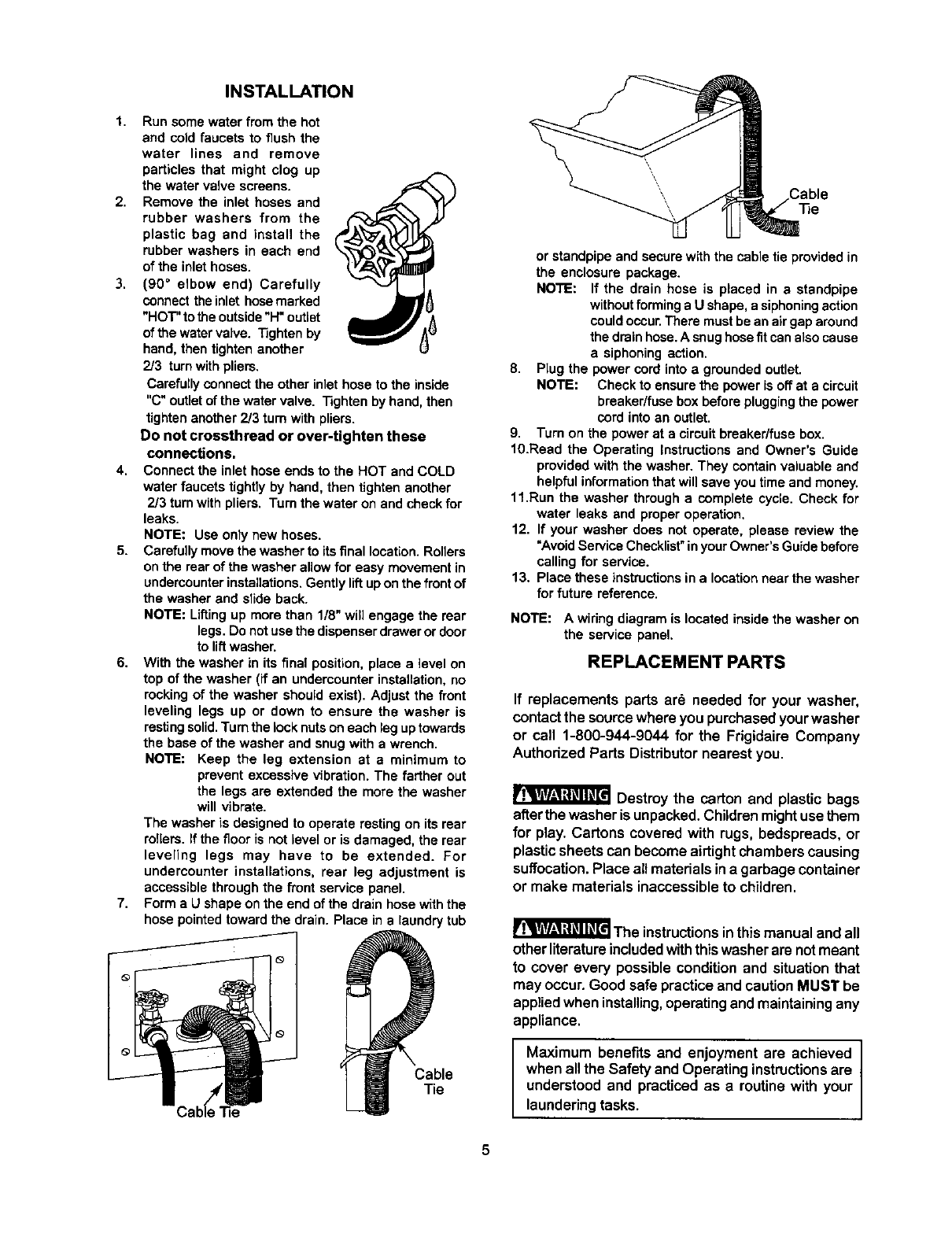
Form a U shape on the end of the drain hose withthe
hose pointedtoward the drain. Place in a laundry tub
Cable
Tie
or standpipe and secure with the cable tie provided in
the enclosure package.
NOTE: If the drain hose is placed in astandpipe
without forming a Ushape, a siphoning action
could occur. There must be an air gap around
the drain hose. A snug hose fit can also cause
a siphoning action.
8. Plug the power cord into agrounded outlet.
NOTE: Check to ensure the power is off at a circuit
breaker/fuse box before plugging the power
cord into an outlet.
9. Turn on the power at a circuit breaker/fuse box.
10.Read the Operating Instructions and Owner's Guide
provided with the washer. They contain valuable and
helpful information that will save you time and money.
11.Run the washer through acomplete cycle. Check for
water leaks and proper operation.
12. If your washer does not operate, please review the
"Avoid Service Checklist" in your Owner's Guide before
calling for service.
13. Place these instructions in alocation near the washer
for future reference.
NOTE: A wiring diagram is located inside the washer on
the service panel,
REPLACEMENT PARTS
If replacements parts are needed for your washer,
contactthe sourcewhere you purchased yourwasher
or cell 1-800-944-9044 for the Frigidaire Company
Authorized Parts Distributornearest you.
Destroy the carton and plastic bags
afterthe washer is unpacked.Children might use them
for play. Cartons covered with rugs, bedspreads, or
plastic sheets can become airtight chambers causing
suffocation. Place all matedals in a garbage container
or make materials inaccessible to children.
I&l_ll, R_q_qvm
r l'=vw-'l_='n=_'==='lThe instructionsinthis manual and all
other literature includedwiththis washerare notmeant
to cover every possible condition and situationthat
may occur. Good safe practice and cautionMUST be
appliedwhen installing,operatingand maintainingany
appliance.
Maximum benefits and enjoyment are achieved I
when all the Safety and Operating instructions are I
understood and practiced as aroutine with your
laundering tasks.
