Fu Hsing A04 Proximity Card Electronic Deadbolt User Manual
Taiwan Fu Hsing Industrial Co., Ltd. Proximity Card Electronic Deadbolt Users Manual
UserManual.wiki
>
Fu Hsing
>
A04 User Manual
Users Manual
Navigation menu
Upload a User Manual
Namespaces
Wiki Guide
HTML
PDF
Info
Views
User Manual
Discussion / Help
Navigation
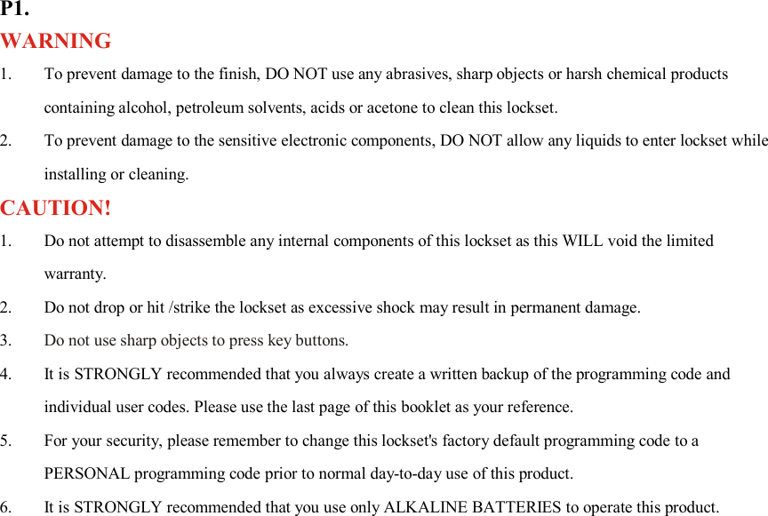
![P23. INSTALLATION INSTRUCTIONS: AUTOMATIC - BOLT DIRECTION DETERMINATION Note: We recommend to do bolt direction determination first once the lockset is installed on the door. Steps: 1. Press and hold [SET] button for over 2 seconds. The Red LED will light up and beep twice. You are now under setup mode. 2. Enter 123456 (or current programming code) and then press button. Enter [00] and press button. The Red LED will light up for 10 seconds. The lockset will have the bolt direction set.](https://usermanual.wiki/Fu-Hsing/A04/User-Guide-1710921-Page-25.png)
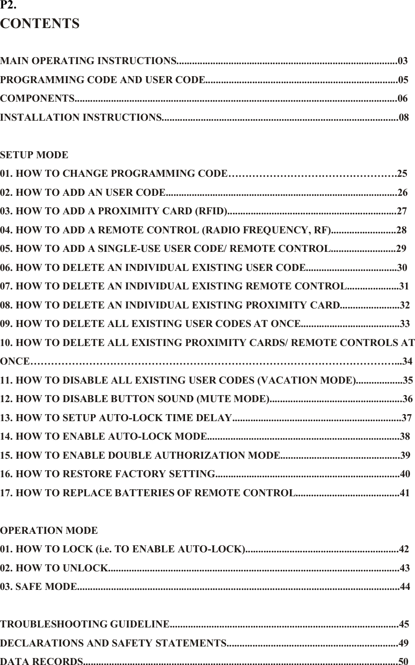
![P25. SETUP MODE HOW TO CHANGE PROGRAMMING CODE Important: The pre-set programming code is 1-2-3-4-5-6. Please change the programming code before operating the lockset. Steps as following: 1. Press and hold [SET] button for over 2 seconds. The Red LED will light up and beep twice. You are now under setup mode. 2. Enter 123456 (or current programming code) and then press button . Enter [10] and press button . Enter new programming code (six digits) and press button . 3. The Red LED will light up for 10 seconds. The lockset will have the new programming code set. Note: 1. The lockset will go back to the standby status if no button is pressed in 10 seconds after accessing setup mode. 2. If you enter new programming code in 10 seconds after accessing setup mode, the last programming code will be stored in the lockset.](https://usermanual.wiki/Fu-Hsing/A04/User-Guide-1710921-Page-27.png)
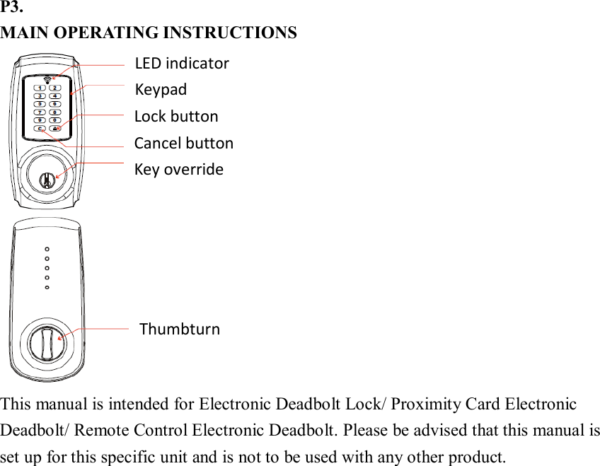
![P26. SETUP MODE HOW TO ADD AN USER CODE Steps as following: 1. Press and hold [SET] button for over 2 seconds. The Red LED will light up and beep twice. You are now under setup mode. 2. Enter 123456 (or current programming code) and then press button . Enter [20] and press button . Enter new user code (four to six digits) and press button . 3. The Red LED will light up for 10 seconds. The lockset will have the new user code set. (If a number of user codes are to be added at the same time, enter new user code and press prior to the indicator light timing out 10 seconds after the last press of a keypad button.) Note: 1. The lockset will go back to the standby status if no button is pressed in 10 seconds after accessing setup mode.](https://usermanual.wiki/Fu-Hsing/A04/User-Guide-1710921-Page-28.png)
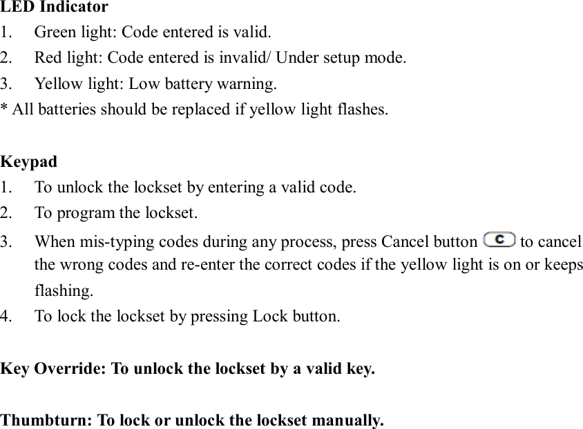
![P27. SETUP MODE HOW TO ADD A PROXIMITY CARD (only available for Proximity Card Electronic Deadbolt) Steps as following: 1. Press and hold [SET] button for over 2 seconds. The Red LED will light up and beep twice. You are now under setup mode. 2. Enter 123456 (or current programming code) and then press button . Enter [20] and press button . Put card to contact with the inductive zone. 3. The Red LED will light up for 10 seconds. The lockset will have the new card set. (If a number of proximity cards are to be added at the same time, use new card to contact with the inductive zone prior to the indicator light timing out 10 seconds after the last press of a keypad button.) Note: 1. The lockset will go back to the standby status if no button is pressed in 10 seconds after accessing setup mode. 2. Please use or purchase proximity cards compatible with standard Mifare -13.56 MHz if you want to have more than one proximity card. 3. Proximity card capacity: 10 sets maximum.](https://usermanual.wiki/Fu-Hsing/A04/User-Guide-1710921-Page-29.png)
![P28. SETUP MODE HOW TO ADD A REMOTE CONTROL (only available for Remote Control Electronic Deadbolt) Steps as following: 1. Press and hold [SET] button for over 2 seconds. The Red LED will light up and beep twice. You are now under setup mode. 2. Enter 123456 (or current programming code) and then press button . Enter [20] and press button . Press any button on the remote control and press button . 3. The Red LED will light up for 10 seconds. The lockset will have the new remote control set. (If a number of remote controls are to be added at the same time, press any button of the every remote control consecutively and press button finally prior to the indicator light timing out 10 seconds after the last press of a keypad button.) Note: 1. The lockset will go back to the standby status if no button is pressed in 10 seconds after accessing setup mode. 2. Please purchase a remote control (produced by our company) from an authorized retailer if you want to have more than one remote control. 3. Remote control capacity: 10 sets maximum.](https://usermanual.wiki/Fu-Hsing/A04/User-Guide-1710921-Page-30.png)
![P29. SETUP MODE HOW TO ADD A SINGLE-USE USER CODE/ REMOTE CONTROL (single-use remote control only available for Remote Control Electronic Deadbolt) Steps as following: 1. Press and hold [SET] button for over 2 seconds. The Red LED will light up and beep twice. You are now under setup mode. 2. Enter 123456 (or current programming code) and then press button . 3. Please turn on auto-lock mode according to page 38 before following the below steps to enable single-use user code/ remote control. single-use Follow the below steps. User code Enter [21] Press button Enter user codes (4 to 6 digits) Press button User codes could be stored to 5 sets Remote control Press any button on the remote control Press button Remote controls could be stored to 5 sets Note: 1. The lockset will go back to the standby status if no button is pressed in 10 seconds after accessing setup mode. 2. Single-use user code capacity: 5 sets maximum. 3. Single-use remote control capacity: 5 sets maximum. 4. Single-entry user code/single-entry user remote control is only allowed to work once and will become invalid after one use (entry). 5. Do not use your multiple-entry user code/ multiple-entry remote control to facilitate single-entry operation, or your user code and remote control will become invalid after only one use (entry).](https://usermanual.wiki/Fu-Hsing/A04/User-Guide-1710921-Page-31.png)
![P30. SETUP MODE HOW TO DELETE AN INDIVIDUAL EXISTING USER CODE Steps as following: 1. Press and hold [SET] button for over 2 seconds. The Red LED will light up and beep twice. You are now under setup mode. 2. Enter 123456 (or a current programming code) and then press button . Enter [30] and press button . Enter existing user code (that you wish to delete) and press button . 3. The Red LED will light up for 10 seconds. The lockset will delete the existing user code that you do not want. (If a number of user codes are to be deleted at the same time, enter each user code to be deleted and press prior to the indicator light timing out 10 seconds after the last press of a keypad button.) Note: 1. The lockset will go back to the standby status if no button is pressed in 10 seconds after accessing setup mode.](https://usermanual.wiki/Fu-Hsing/A04/User-Guide-1710921-Page-32.png)
![P31. SETUP MODE HOW TO DELETE AN INDIVIDUAL EXISTING REMOTE CONTROL (only available for Remote Control Electronic Deadbolt) Steps as following: 1. Press and hold [SET] button for over 2 seconds. The Red LED will light up and beep twice. You are now under setup mode. 2. Enter 123456 (or current programming code) and then press button . Enter [30] and press button . Press any button on the remote control (that you wish to delete) and press button . 3. The Red LED will light up for 10 seconds. The lockset will delete the existing remote control that you do not want. (If a number of remote controls are to be deleted at the same time, press any button of the every remote control consecutively and press button finally prior to the indicator light timing out 10 seconds after the last press of a keypad button.) Note: 1. The lockset will go back to the standby status if no button is pressed in 10 seconds after accessing setup mode. 2. If any remote control is lost, for your safety, please delete all remote controls and re-add current remote controls excluding the lost one.](https://usermanual.wiki/Fu-Hsing/A04/User-Guide-1710921-Page-33.png)
![P32. SETUP MODE HOW TO DELETE AN INDIVIDUAL EXISTING PROXIMITY CARD (only available for Proximity Card Electronic Deadbolt) Steps as following: 1. Press and hold [SET] button for over 2 seconds. The Red LED will light up and beep twice. You are now under setup mode. 2. Enter 123456 (or current programming code) and then press button . Enter [30] and press button . Put the card that you wish to delete to contact with the inductive zone. 3. The Red LED will light up for 10 seconds. The lockset will delete the existing card that you do not want. (If a number of cards are to be deleted at the same time, use every card to contact with the inductive consecutively prior to the indicator light timing out 10 seconds after the last press of a keypad button.) Note: 1. The lockset will go back to the standby status if no button is pressed in 10 seconds after accessing setup mode. 2. If any card is lost, for your safety, please delete all cards and re-add current cards excluding the lost one.](https://usermanual.wiki/Fu-Hsing/A04/User-Guide-1710921-Page-34.png)
![P33. SETUP MODE HOW TO DELETE ALL EXISTING USER CODES AT ONCE Steps as following: 1. Press and hold [SET] button for over 2 seconds. The Red LED will light up and beep twice. You are now under setup mode. 2. Enter 123456 (or current programming code) and then press button . Enter [40] and press button . 3. The Red LED will light up for 10 seconds. The lockset will delete all existing user codes. Note: 1. The lockset will go back to the standby status if no button is pressed in 10 seconds after accessing setup mode.](https://usermanual.wiki/Fu-Hsing/A04/User-Guide-1710921-Page-35.png)
![P34. SETUP MODE HOW TO DELETE ALL EXISTING PROXIMITY CARDS/ REMOTE CONTROLS AT ONCE (only available for Proximity Card Electronic Deadbolt/ Remote Control Electronic Deadbolt) Steps as following: 1. Press and hold [SET] button for over 2 seconds. The Red LED will light up and beep twice. You are now under setup mode. 2. Enter 123456 (or current programming code) and then press button . Enter [41] and press button . 3. The Red LED will light up for 10 seconds. The lockset will delete all existing cards and remote controls. Note: 1. The lockset will go back to the standby status if no button is pressed in 10 seconds after accessing setup mode. 2. If any card/ remote control is lost, for your safety, please delete all cards/ remote controls and re-add current cards/ remote controls excluding the lost one.](https://usermanual.wiki/Fu-Hsing/A04/User-Guide-1710921-Page-36.png)
![P35. SETUP MODE HOW TO DISABLE ALL EXISTING USER CODES (VACATION MODE) Steps as following: 1. Press and hold [SET] button for over 2 seconds. The Red LED will light up and beep twice. You are now under setup mode. 2. Enter 123456 (or current programming code) and then press button . Enter [50] and press button . 3. Enter [0] and press button . The Red LED will light up for 10 seconds. The lockset will turn on vacation mode. 4. Enter [1] and press button . The Red LED will light up for 10 seconds. The lockset will turn off vacation mode. (Default vacation mode is off) Note: 1. The lockset will go back to the standby status if no button is pressed in 10 seconds after accessing setup mode. 2. Vacation mode is used to disable all user codes at the keypad. If a valid user code is entered while the lock is in vacation mode, the lock will not unlock. If you will be away from your home for a period of, it is a good idea to use vacation mode to prevent repeated access attempts.](https://usermanual.wiki/Fu-Hsing/A04/User-Guide-1710921-Page-37.png)
![P36. SETUP MODE HOW TO DISABLE BUTTON SOUND (MUTE MODE) Steps as following: 1. Press and hold [SET] button for over 2 seconds. The Red LED will light up and beep twice. You are now under setup mode. 2. Enter 123456 (or current programming code) and then press button . Enter [60] and press button again. 3. Enter [0] and press button . The Red LED will light up for 10 seconds. The lockset will turn on mute mode. 4. Enter [1] and press button . The Red LED will light up for 10 seconds. The lockset will turn off mute mode. (Default mute mode is off.) Note: 1. The lockset will go back to the standby status if no button is pressed in 10 seconds after accessing setup mode.](https://usermanual.wiki/Fu-Hsing/A04/User-Guide-1710921-Page-38.png)
![P37. SETUP MODE HOW TO SETUP AUTO-LOCK TIME DELAY Steps as following: 1. Press and hold [SET] button for over 2 seconds. The Red LED will light up and beep twice. You are now under setup mode. 2. Enter 123456 (or current programming code) and then press button . Enter [70] and press button . Enter the seconds for delay time of auto-locking (10 to 90) and press button . 3. The Red LED will light up for 10 seconds. The lockset will setup auto-lock time delay. Note: 1. The lockset will go back to the standby status if no button is pressed in 10 seconds after accessing setup mode. 2. The lockset will flash and beep three times if the seconds for delay time of auto-locking is not within 10 to 90 seconds. 3. Default auto-lock time delay is 10 seconds.](https://usermanual.wiki/Fu-Hsing/A04/User-Guide-1710921-Page-39.png)
![P38. SETUP MODE HOW TO ENABLE AUTO-LOCK MODE Steps as following: 1. Press and hold [SET] button for over 2 seconds. The Red LED will light up and beep twice. You are now under setup mode. 2. Enter 123456 (or current programming code) and then press button . Enter [80] and press button . 3. Enter [0] and press button . The Red LED will light up for 10 seconds. The lockset will turn on auto-lock mode. 4. Enter [1] and press button . The Red LED will light up for 10 seconds. The lockset will turn off auto-lock mode. (Default auto-lock mode is off) Note: 1. The lockset will go back to the standby status if no button is pressed in 10 seconds after accessing setup mode. 2. The lockset will auto-lock in 10 seconds (default value) without flashing and beeping after unlocking if you turn on auto-lock mode. 3. The lockset can still be locked by pressing button manually even if you turn on auto-lock mode.](https://usermanual.wiki/Fu-Hsing/A04/User-Guide-1710921-Page-40.png)
![P39. SETUP MODE HOW TO ENABLE DOUBLE AUTHORIZATION MODE (only available for Proximity Card Electronic Deadbolt/ Remote Control Electronic Deadbolt) Steps as following: 1. Press and hold [SET] button for over 2 seconds. The Red LED will light up and beep twice. You are now under setup mode. 2. Enter 123456 (or current programming code) and then press button . Enter [99] and press button . 3. Enter [0] and press button . The Red LED will light up for 10 seconds. The lockset will turn on double authorization mode. (When double authorization mode is turned on, both user code and card, or, both user code and remote control must be authenticated to unlock the lockset.) 4. Enter [1] and press button . The Red LED will light up for 10 seconds. The lockset will turn off double authorization mode. (Default double authorization mode is off.) Note: 1. The lockset will go back to the standby status if no button is pressed in 10 seconds after accessing setup mode. 2. Please make sure that both user code and card, or both user code and remote control, are stored in the lockset before you turn on double authorization mode.](https://usermanual.wiki/Fu-Hsing/A04/User-Guide-1710921-Page-41.png)
![P40. SETUP MODE HOW TO RESTORE FACTORY SETTING Steps as following: 1. Remove one battery from the battery pack. 2. Press [SET] button and put the battery back simultaneously. The Green LED will light up and beep twice. All functions will be restored back to factory setting. Note: 1. All existing user codes and current programming code will be deleted. 2. Lock will be restored to pre-set programming code of 1-2-3-4-5-6. 3. Please change the programming code and add a new user code immediately before operating the lockset.](https://usermanual.wiki/Fu-Hsing/A04/User-Guide-1710921-Page-42.png)
![P45. TROUBLESHOOTING GUIDELINE QUESTIONS ANSWERS The lockset did not operate correctly after installation. 1. Check center of strike hole for alignment with latch hole on the door to ensure free movement for the deadbolt. 2. Make sure the tailpiece is properly inserted (in the horizontal position) in the latch. 3. Do [AUTOMATIC -BOLT DIRECTION DETERMINATION]. Feel a bump while turning of the motor. 1. Please rotate the thumbturn back and forth a few times. Feel a bump while turning the thumbturn or the key. 1. Please execute lock & unlock function to allow the motor for repositioning again. Keypad is not response at all. 1. Check to see if the batteries are well-installed. 2. Check to see if the Yellow LED light is flashing or not. It means "low battery" when the light keeps flashing. 3. Make sure the cable is well-connected to the port. Programming code cannot be changed. 1. Please complete the "HOW TO CHANGE PROGRAMMING CODE" process by inputting codes within 10 seconds. 2. Please make sure you have entered the new programming code twice correctly or go back to the factory setting and reset the programming code again. I cannot delete all user codes. 1. Make sure all code inputting processes should be completed within 10 seconds. 2. Make sure you have entered the correct programming code. 3. button should be held over 3 seconds. I cannot add a new user code. 1. Make sure all code inputting processes should be completed within 10 seconds. 2. Make sure you have entered the correct programming code.](https://usermanual.wiki/Fu-Hsing/A04/User-Guide-1710921-Page-47.png)
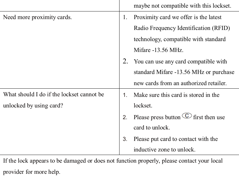
![3. The new user code will not be accepted if 10 sets of user codes are already stored in the memory. The lockset is not able to unlock by the keypad 1. Make sure you have entered the correct user code. 2. Check to see if the Yellow LED light is flashing or not. It means "low battery" if the light keeps flashing. 3. Please make sure the position of strike plate is installed correctly if you see the latch is jammed. I am unable to reset the lockset. 1. Please refer to "HOW TO RESTORE FACTORY SETTING” section and make sure all steps are followed correctly. 2. Check to see if the Yellow LED light is flashing or not. It means "low battery" if the light keeps flashing. Red LED light is still on after setting is completed. 1. Please make sure if [SET] button is jammed. 2. Please re-install the batteries. "Auto lock" is malfunction. 1. Please make sure turn on auto-lock mode. 2. Check to see if the Yellow LED light is flashing or not. It means "low battery" if the light keeps flashing. Yellow LED light keeps flashing. The battery is getting low, please reinstall all new batteries for best performance (AA size Alkaline batteries are only allowed). What should I do if I input the wrong code? 1. Press button once and continue to input code according to regular procedures. How to operate this lock under a dark situation? 1. Press any button on the keypad to initiate LED backlight. Card or remote control is lost. 1. For your safety, please delete all cards/ remote controls and re-add current cards/ remote controls excluding the lost one. Need more remote controls. 1. Please purchase the remote control (produced by our company) from an authorized retailer. Other remote controls](https://usermanual.wiki/Fu-Hsing/A04/User-Guide-1710921-Page-48.png)