Fu Hsing A04 Proximity Card Electronic Deadbolt User Manual
Taiwan Fu Hsing Industrial Co., Ltd. Proximity Card Electronic Deadbolt Users Manual
Fu Hsing >
Users Manual
P1.
WARNING
1. To prevent damage to the finish, DO NOT use any abrasives, sharp objects or harsh chemical products
containing alcohol, petroleum solvents, acids or acetone to clean this lockset.
2. To prevent damage to the sensitive electronic components, DO NOT allow any liquids to enter lockset while
installing or cleaning.
CAUTION!
1. Do not attempt to disassemble any internal components of this lockset as this WILL void the limited
warranty.
2. Do not drop or hit /strike the lockset as excessive shock may result in permanent damage.
3. Do not use sharp objects to press key buttons.
4. It is STRONGLY recommended that you always create a written backup of the programming code and
individual user codes. Please use the last page of this booklet as your reference.
5. For your security, please remember to change this lockset's factory default programming code to a
PERSONAL programming code prior to normal day-to-day use of this product.
6. It is STRONGLY recommended that you use only ALKALINE BATTERIES to operate this product.
P2.
CONTENTS
MAIN OPERATING INSTRUCTIONS.....................................................................................03
PROGRAMMING CODE AND USER CODE..........................................................................05
COMPONENTS............................................................................................................................06
INSTALLATION INSTRUCTIONS...........................................................................................08
SETUP MODE
01. HOW TO CHANGE PROGRAMMING CODE………………………………………….25
02. HOW TO ADD AN USER CODE.........................................................................................26
03. HOW TO ADD A PROXIMITY CARD (RFID).................................................................27
04. HOW TO ADD A REMOTE CONTROL (RADIO FREQUENCY, RF).........................28
05. HOW TO ADD A SINGLE-USE USER CODE/ REMOTE CONTROL.........................29
06. HOW TO DELETE AN INDIVIDUAL EXISTING USER CODE...................................30
07. HOW TO DELETE AN INDIVIDUAL EXISTING REMOTE CONTROL....................31
08. HOW TO DELETE AN INDIVIDUAL EXISTING PROXIMITY CARD.......................32
09. HOW TO DELETE ALL EXISTING USER CODES AT ONCE......................................33
10. HOW TO DELETE ALL EXISTING PROXIMITY CARDS/ REMOTE CONTROLS AT
ONCE……………………………………………………………………………………………...34
11. HOW TO DISABLE ALL EXISTING USER CODES (VACATION MODE)..................35
12. HOW TO DISABLE BUTTON SOUND (MUTE MODE)...................................................36
13. HOW TO SETUP AUTO-LOCK TIME DELAY.................................................................37
14. HOW TO ENABLE AUTO-LOCK MODE..........................................................................38
15. HOW TO ENABLE DOUBLE AUTHORIZATION MODE..............................................39
16. HOW TO RESTORE FACTORY SETTING.......................................................................40
17. HOW TO REPLACE BATTERIES OF REMOTE CONTROL........................................41
OPERATION MODE
01. HOW TO LOCK (i.e. TO ENABLE AUTO-LOCK)...........................................................42
02. HOW TO UNLOCK................................................................................................................43
03. SAFE MODE............................................................................................................................44
TROUBLESHOOTING GUIDELINE........................................................................................45
DECLARATIONS AND SAFETY STATEMENTS..................................................................49
DATA RECORDS.........................................................................................................................50
P3.
MAIN OPERATING INSTRUCTIONS
This manual is intended for Electronic Deadbolt Lock/ Proximity Card Electronic
Deadbolt/ Remote Control Electronic Deadbolt. Please be advised that this manual is
set up for this specific unit and is not to be used with any other product.
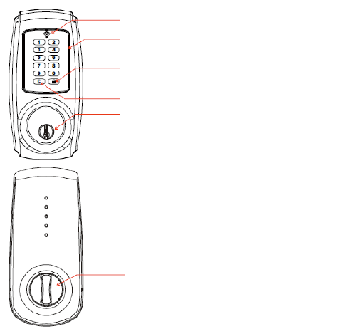
Lock button
Cancel button
Key override
LED indicator
Keypad
Thumbturn

LED Indicator
1. Green light: Code entered is valid.
2. Red light: Code entered is invalid/ Under setup mode.
3. Yellow light: Low battery warning.
* All batteries should be replaced if yellow light flashes.
Keypad
1. To unlock the lockset by entering a valid code.
2. To program the lockset.
3. When mis-typing codes during any process, press Cancel button to cancel
the wrong codes and re-enter the correct codes if the yellow light is on or keeps
flashing.
4. To lock the lockset by pressing Lock button.
Key Override: To unlock the lockset by a valid key.
Thumbturn: To lock or unlock the lockset manually.
P4.
MAIN OPERATING INSTRUCTIONS
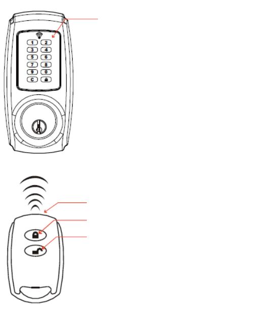
Inductive Zone (only available for Proximity Card Electronic Deadbolt)
1. Inductive zone is around the keypad.
2. The proximity card we offer is the latest Radio Frequency Identification (RFID)
technology, compatible with standard Mifare -13.56 MHz.
3. Please contact the proximity card with the inductive zone.
Remote Control (Radio Frequency, RF) (only available for Remote Control Electronic
Deadbolt)
1. There is one unlock button and one lock button on the remote control.
2. We recommend the operating distance between the remote control and the
lockset is within 50ft (15m.) This is maximum distance under the circumstance
that no objects block the emission of the remote control toward the lockset.
3. The LED of the remote control will light on when holding the lock button on the
remote for 3 seconds.
Inductive Zone
LED
Lock button
Unlock button
P5.
PROGRAMMING CODE AND USER CODE
PROGRAMMING CODE
1. Only one programming code will be allowed, and the lockset can be
programmed by entering the programming code.
2. A programming code is restricted to 6-digits in length only. The pre-set
programming code is 1-2-3-4-5-6 (factory setting), please change it before
operating the lockset.
3. The lockset can be unlocked by entering programming code.
USER CODE
1. A user code can be from four (4) to six (6) digits in length.
2. A user code can be changed (added or deleted) by accessing the setup mode.
3. The lockset cannot be programmed by entering the user code.
4. The lockset will unlock by entering the user code.
Note:
User code capacity: 10 sets maximum.
Proximity card capacity: 10 sets maximum.
Remote control capacity: 10 sets maximum.
P6.
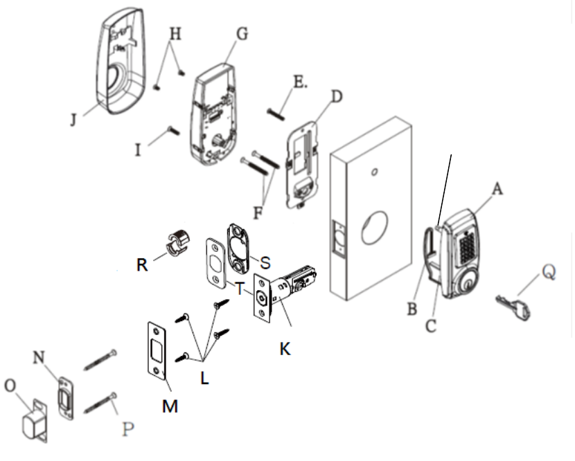
COMPONENTS
A. Exterior Assembly
B. Cable
C. Tailpiece
D. Mounting Plate
U
P7.
E. 1-1/4" (32mm) Screw (1)
F. 2-1/8" (54mm) Mounting Bolt (2)
G. Interior Assembly
H. 5/16" (7.8mm) Screw (2)
I. 13/16" (20mm) Screw (1)
J. Decorative Cover
K. Adjustable Latch (Square or radius faceplate or drive-in)
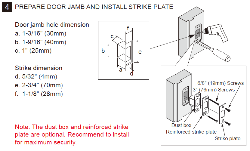
L. 6/8" (19mm) Wood Screw (4)
M. Strike Plate
N. Reinforced Strike Plate
O. Dust Box
P. 3" (76mm) Wood Screw (2)
Q. Key (2)
R. Drive in Collar (Optional)
S. Bottom Plate (Optional)
T. Square or Radius Faceplate (Optional)
U. Screw post
P8.
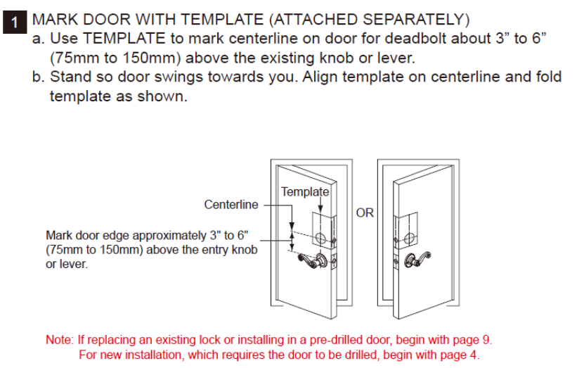
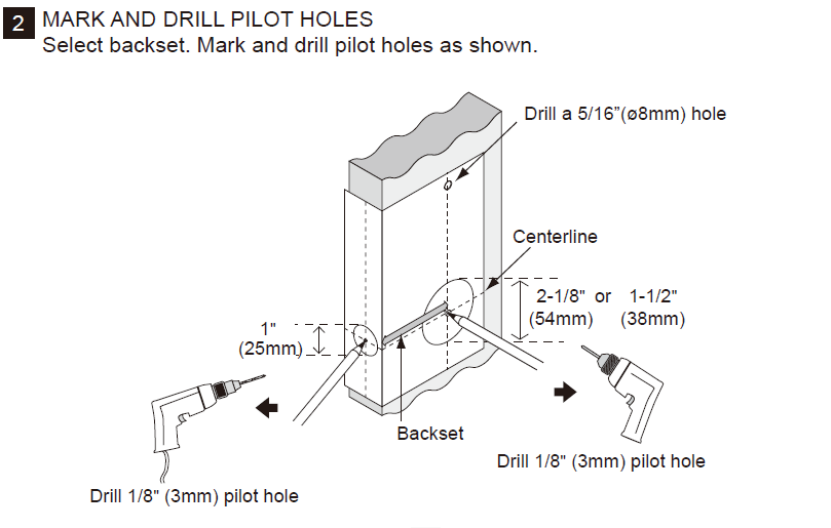
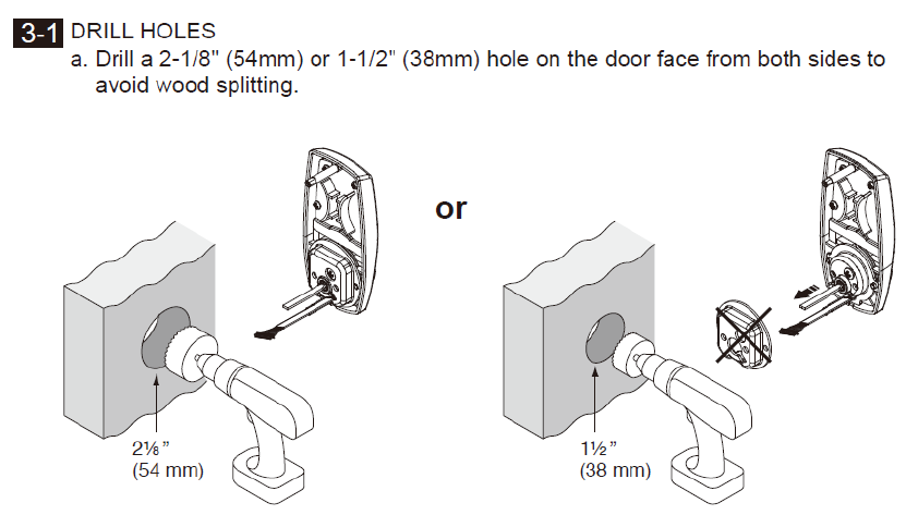
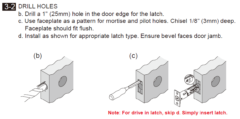
INSTALLATION INSTRUCTIONS: DOOR PREPARATION
P9.
INSTALLATION INSTRUCTION
P10.
INSTALLATION INSTRUCTIONS
P11.
INSTALLATION INSTRUCTION
P12.
INSTALLATION INSTRUCTIONS
P13.
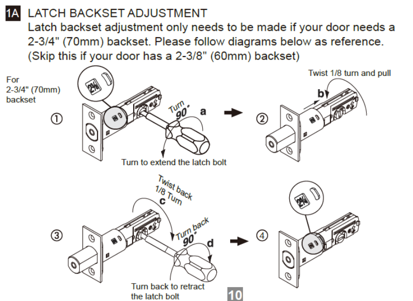
INSTALLATION INSTRUCTIONS: LATCH BASKET ADJUSTMENT
P14.
INSTALLATION INSTRUCTION
P15.
INSTALLATION INSTRUCTION
P16.
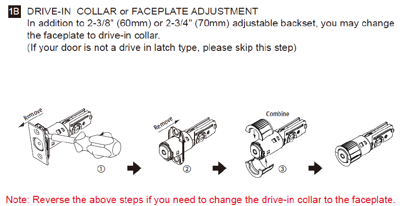
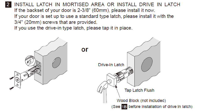
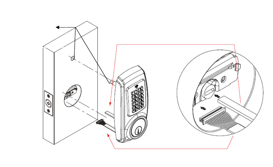
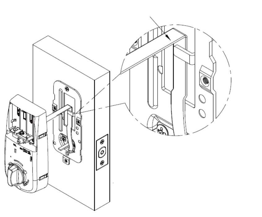
INSTALLATION INSTRUCTIONS: COMBINE THE EXTERIOR ASSEMBLY
WITH LATCH
Drill a 5/16”(ø8mm)
hole on the door when
the screw post is
installed.
Place the cable underneath the latch
Move the tailpiece horizontally into the latch
P17.
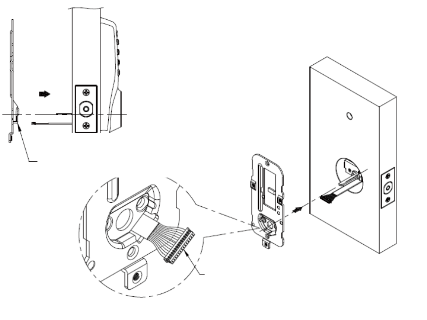
INSTALLATION INSTRUCTION: COMBINE THE MOUNTING PLATE
WITH THE EXTERIOR ASSEMBLY
The bulged part of mounting plate must
face toward the door
Slide cable through the notch of mounting plate
P18.
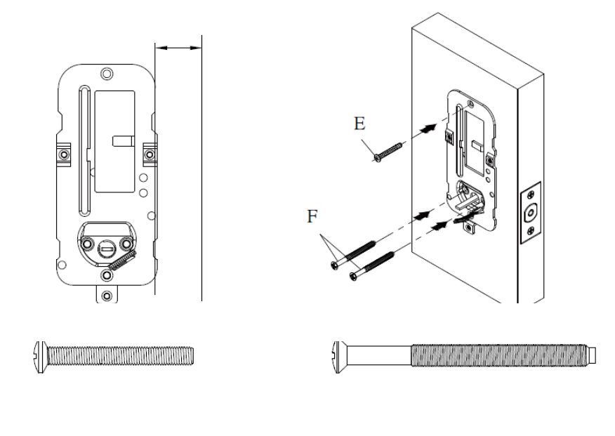
INSTALLATION INSTRUCTION
Fasten the mounting plate with 2-1/8" (54mm) screws*2 and 1-1/4" (32mm) screw*1
Make sure the mounting plate is parallel with the edge of the door
Note: Screw (E) is an optional screw. We recommend using screw (E)
for the stability of the lockset.
P19.
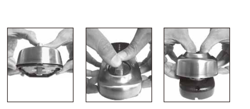
INSTALLATION INSTRUCTIONS: REMOVE THE DECORATIVE COVER
1. Hold on the lip of the
decorative cover
2. Put the thumbs on the
thumbturn
3. Remove the decorative cover
by pushing the thumbturn.
P20.
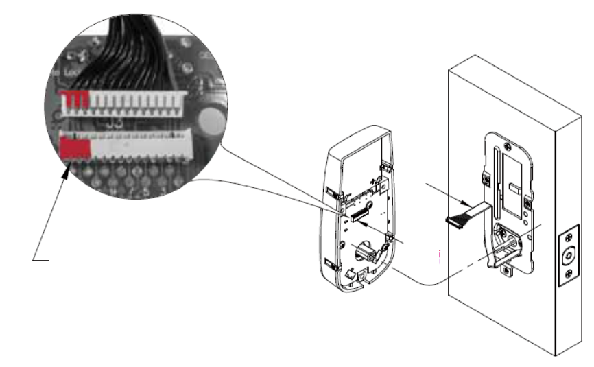
INSTALLATION INSTRUCTIONS: CONNECTING THE CABLE
Connect the cable into the connector port.
The metal connector side should face outside.
Cable
Note: The red portion of the cable is aligned with the red portion of the connector port.
Connector port
P21.
INSTALLATION INSTRUCTIONS
The cable must be arranged as shown in the diagram.
P22.
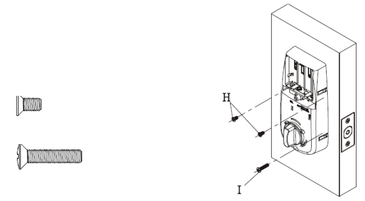
INSTALLATION INSTRUCTIONS: INSTALL THE INTERIOR ASSEMBLY
Tighten three screws as
shown below
Insert 5/16" (7.8mm) screws "H"
and tighten
Insert 13/16" (20mm) screw "I" and tighten.
P23.
INSTALLATION INSTRUCTIONS: AUTOMATIC - BOLT DIRECTION
DETERMINATION
Note: We recommend to do bolt direction determination first once the lockset is
installed on the door.
Steps:
1. Press and hold [SET] button for over 2 seconds. The Red LED will light up and beep twice.
You are now under setup mode.
2. Enter 123456 (or current programming code) and then press button. Enter [00] and
press button. The Red LED will light up for 10 seconds. The lockset will have the bolt
direction set.
P24.
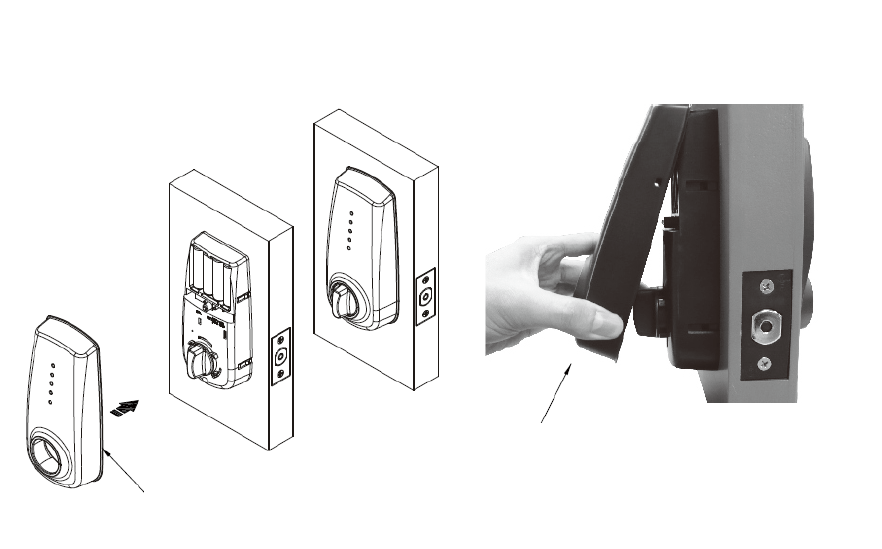
INSTALLATION INSTRUCTIONS: RE-INSTALL THE DECORATIVE COVER
We recommend re-installing the decorative cover after completing setup mode in page 18 to page 30.
If you want to remove the decorative cover,
please hold the bottom of the decorative cover
and pull it toward yourself.
Re-install the
decorative cover
P25.
SETUP MODE
HOW TO CHANGE PROGRAMMING CODE
Important:
The pre-set programming code is 1-2-3-4-5-6.
Please change the programming code before operating the lockset.
Steps as following:
1. Press and hold [SET] button for over 2 seconds. The Red LED will light up and beep twice. You
are now under setup mode.
2. Enter 123456 (or current programming code) and then press button . Enter [10] and press
button . Enter new programming code (six digits) and press button .
3. The Red LED will light up for 10 seconds. The lockset will have the new programming code set.
Note:
1. The lockset will go back to the standby status if no button is pressed in 10 seconds after
accessing setup mode.
2. If you enter new programming code in 10 seconds after accessing setup mode, the last
programming code will be stored in the lockset.
P26.
SETUP MODE
HOW TO ADD AN USER CODE
Steps as following:
1. Press and hold [SET] button for over 2 seconds. The Red LED will light up and beep twice. You
are now under setup mode.
2. Enter 123456 (or current programming code) and then press button . Enter [20] and press
button . Enter new user code (four to six digits) and press button .
3. The Red LED will light up for 10 seconds. The lockset will have the new user code set.
(If a number of user codes are to be added at the same time, enter new user code and press prior to the
indicator light timing out 10 seconds after the last press of a keypad button.)
Note:
1. The lockset will go back to the standby status if no button is pressed in 10 seconds after
accessing setup mode.
P27.
SETUP MODE
HOW TO ADD A PROXIMITY CARD (only available for Proximity Card Electronic Deadbolt)
Steps as following:
1. Press and hold [SET] button for over 2 seconds. The Red LED will light up and beep twice. You
are now under setup mode.
2. Enter 123456 (or current programming code) and then press button . Enter [20] and press
button . Put card to contact with the inductive zone.
3. The Red LED will light up for 10 seconds. The lockset will have the new card set.
(If a number of proximity cards are to be added at the same time, use new card to contact with the inductive zone
prior to the indicator light timing out 10 seconds after the last press of a keypad button.)
Note:
1. The lockset will go back to the standby status if no button is pressed in 10 seconds after
accessing setup mode.
2. Please use or purchase proximity cards compatible with standard Mifare -13.56 MHz if
you want to have more than one proximity card.
3. Proximity card capacity: 10 sets maximum.
P28.
SETUP MODE
HOW TO ADD A REMOTE CONTROL (only available for Remote Control Electronic
Deadbolt)
Steps as following:
1. Press and hold [SET] button for over 2 seconds. The Red LED will light up and beep twice. You
are now under setup mode.
2. Enter 123456 (or current programming code) and then press button . Enter [20] and press
button . Press any button on the remote control and press button .
3. The Red LED will light up for 10 seconds. The lockset will have the new remote control set.
(If a number of remote controls are to be added at the same time, press any button of the every remote control
consecutively and press button finally prior to the indicator light timing out 10 seconds after the last press of
a keypad button.)
Note:
1. The lockset will go back to the standby status if no button is pressed in 10 seconds after
accessing setup mode.
2. Please purchase a remote control (produced by our company) from an authorized
retailer if you want to have more than one remote control.
3. Remote control capacity: 10 sets maximum.
P29.
SETUP MODE
HOW TO ADD A SINGLE-USE USER CODE/ REMOTE CONTROL (single-use remote
control only available for Remote Control Electronic Deadbolt)
Steps as following:
1. Press and hold [SET] button for over 2 seconds. The Red LED will light up and beep twice. You
are now under setup mode.
2. Enter 123456 (or current programming code) and then press button .
3. Please turn on auto-lock mode according to page 38 before following the below steps to enable
single-use user code/ remote control.
single-use Follow the below steps.
User code
Enter [21] Press
button
Enter user
codes (4 to
6 digits)
Press
button
User codes
could be
stored to 5
sets
Remote
control
Press any
button on
the remote
control
Press
button
Remote
controls
could be
stored to 5
sets
Note:
1. The lockset will go back to the standby status if no button is pressed in 10 seconds after
accessing setup mode.
2. Single-use user code capacity: 5 sets maximum.
3. Single-use remote control capacity: 5 sets maximum.
4. Single-entry user code/single-entry user remote control is only allowed to work once and
will become invalid after one use (entry).
5. Do not use your multiple-entry user code/ multiple-entry remote control to facilitate
single-entry operation, or your user code and remote control will become invalid after
only one use (entry).
P30.
SETUP MODE
HOW TO DELETE AN INDIVIDUAL EXISTING USER CODE
Steps as following:
1. Press and hold [SET] button for over 2 seconds. The Red LED will light up and beep twice. You
are now under setup mode.
2. Enter 123456 (or a current programming code) and then press button . Enter [30] and press
button . Enter existing user code (that you wish to delete) and press button .
3. The Red LED will light up for 10 seconds. The lockset will delete the existing user code that you
do not want.
(If a number of user codes are to be deleted at the same time, enter each user code to be deleted and press
prior to the indicator light timing out 10 seconds after the last press of a keypad button.)
Note:
1. The lockset will go back to the standby status if no button is pressed in 10 seconds after
accessing setup mode.
P31.
SETUP MODE
HOW TO DELETE AN INDIVIDUAL EXISTING REMOTE CONTROL (only available for
Remote Control Electronic Deadbolt)
Steps as following:
1. Press and hold [SET] button for over 2 seconds. The Red LED will light up and beep twice. You
are now under setup mode.
2. Enter 123456 (or current programming code) and then press button . Enter [30] and press
button . Press any button on the remote control (that you wish to delete) and press
button .
3. The Red LED will light up for 10 seconds. The lockset will delete the existing remote control
that you do not want.
(If a number of remote controls are to be deleted at the same time, press any button of the every remote control
consecutively and press button finally prior to the indicator light timing out 10 seconds after the last press
of a keypad button.)
Note:
1. The lockset will go back to the standby status if no button is pressed in 10 seconds after
accessing setup mode.
2. If any remote control is lost, for your safety, please delete all remote controls and re-add
current remote controls excluding the lost one.

P32.
SETUP MODE
HOW TO DELETE AN INDIVIDUAL EXISTING PROXIMITY CARD (only available for
Proximity Card Electronic Deadbolt)
Steps as following:
1. Press and hold [SET] button for over 2 seconds. The Red LED will light up and beep twice. You
are now under setup mode.
2. Enter 123456 (or current programming code) and then press button . Enter [30] and press
button . Put the card that you wish to delete to contact with the inductive zone.
3. The Red LED will light up for 10 seconds. The lockset will delete the existing card that you do
not want.
(If a number of cards are to be deleted at the same time, use every card to contact with the inductive consecutively
prior to the indicator light timing out 10 seconds after the last press of a keypad button.)
Note:
1. The lockset will go back to the standby status if no button is pressed in 10 seconds after
accessing setup mode.
2. If any card is lost, for your safety, please delete all cards and re-add current cards
excluding the lost one.

P33.
SETUP MODE
HOW TO DELETE ALL EXISTING USER CODES AT ONCE
Steps as following:
1. Press and hold [SET] button for over 2 seconds. The Red LED will light up and beep twice. You
are now under setup mode.
2. Enter 123456 (or current programming code) and then press button . Enter [40] and press
button .
3. The Red LED will light up for 10 seconds. The lockset will delete all existing user codes.
Note:
1. The lockset will go back to the standby status if no button is pressed in 10 seconds after
accessing setup mode.

P34.
SETUP MODE
HOW TO DELETE ALL EXISTING PROXIMITY CARDS/ REMOTE CONTROLS AT ONCE
(only available for Proximity Card Electronic Deadbolt/ Remote Control Electronic Deadbolt)
Steps as following:
1. Press and hold [SET] button for over 2 seconds. The Red LED will light up and beep twice. You
are now under setup mode.
2. Enter 123456 (or current programming code) and then press button . Enter [41] and press
button .
3. The Red LED will light up for 10 seconds. The lockset will delete all existing cards and remote
controls.
Note:
1. The lockset will go back to the standby status if no button is pressed in 10 seconds after
accessing setup mode.
2. If any card/ remote control is lost, for your safety, please delete all cards/ remote controls
and re-add current cards/ remote controls excluding the lost one.
P35.
SETUP MODE
HOW TO DISABLE ALL EXISTING USER CODES (VACATION MODE)
Steps as following:
1. Press and hold [SET] button for over 2 seconds. The Red LED will light up and beep twice. You
are now under setup mode.
2. Enter 123456 (or current programming code) and then press button . Enter [50] and press
button .
3. Enter [0] and press button . The Red LED will light up for 10 seconds. The lockset will turn
on vacation mode.
4. Enter [1] and press button . The Red LED will light up for 10 seconds. The lockset will turn
off vacation mode. (Default vacation mode is off)
Note:
1. The lockset will go back to the standby status if no button is pressed in 10 seconds after
accessing setup mode.
2. Vacation mode is used to disable all user codes at the keypad. If a valid user code is
entered while the lock is in vacation mode, the lock will not unlock. If you will be away
from your home for a period of, it is a good idea to use vacation mode to prevent
repeated access attempts.
P36.
SETUP MODE
HOW TO DISABLE BUTTON SOUND (MUTE MODE)
Steps as following:
1. Press and hold [SET] button for over 2 seconds. The Red LED will light up and beep twice. You
are now under setup mode.
2. Enter 123456 (or current programming code) and then press button . Enter [60] and press
button again.
3. Enter [0] and press button . The Red LED will light up for 10 seconds. The lockset will turn
on mute mode.
4. Enter [1] and press button . The Red LED will light up for 10 seconds. The lockset will turn
off mute mode. (Default mute mode is off.)
Note:
1. The lockset will go back to the standby status if no button is pressed in 10 seconds after
accessing setup mode.

P37.
SETUP MODE
HOW TO SETUP AUTO-LOCK TIME DELAY
Steps as following:
1. Press and hold [SET] button for over 2 seconds. The Red LED will light up and beep twice. You
are now under setup mode.
2. Enter 123456 (or current programming code) and then press button . Enter [70] and press
button . Enter the seconds for delay time of auto-locking (10 to 90) and press button .
3. The Red LED will light up for 10 seconds. The lockset will setup auto-lock time delay.
Note:
1. The lockset will go back to the standby status if no button is pressed in 10 seconds after
accessing setup mode.
2. The lockset will flash and beep three times if the seconds for delay time of auto-locking is
not within 10 to 90 seconds.
3. Default auto-lock time delay is 10 seconds.
P38.
SETUP MODE
HOW TO ENABLE AUTO-LOCK MODE
Steps as following:
1. Press and hold [SET] button for over 2 seconds. The Red LED will light up and beep twice. You
are now under setup mode.
2. Enter 123456 (or current programming code) and then press button . Enter [80] and press
button .
3. Enter [0] and press button . The Red LED will light up for 10 seconds. The lockset will turn
on auto-lock mode.
4. Enter [1] and press button . The Red LED will light up for 10 seconds. The lockset will turn
off auto-lock mode. (Default auto-lock mode is off)
Note:
1. The lockset will go back to the standby status if no button is pressed in 10 seconds after
accessing setup mode.
2. The lockset will auto-lock in 10 seconds (default value) without flashing and beeping
after unlocking if you turn on auto-lock mode.
3. The lockset can still be locked by pressing button manually even if you turn on
auto-lock mode.
P39.
SETUP MODE
HOW TO ENABLE DOUBLE AUTHORIZATION MODE (only available for Proximity Card
Electronic Deadbolt/ Remote Control Electronic Deadbolt)
Steps as following:
1. Press and hold [SET] button for over 2 seconds. The Red LED will light up and beep twice. You
are now under setup mode.
2. Enter 123456 (or current programming code) and then press button . Enter [99] and press
button .
3. Enter [0] and press button . The Red LED will light up for 10 seconds. The lockset will turn
on double authorization mode.
(When double authorization mode is turned on, both user code and card, or, both user code and remote
control must be authenticated to unlock the lockset.)
4. Enter [1] and press button . The Red LED will light up for 10 seconds. The lockset will turn
off double authorization mode. (Default double authorization mode is off.)
Note:
1. The lockset will go back to the standby status if no button is pressed in 10 seconds after
accessing setup mode.
2. Please make sure that both user code and card, or both user code and remote control, are
stored in the lockset before you turn on double authorization mode.
P40.
SETUP MODE
HOW TO RESTORE FACTORY SETTING
Steps as following:
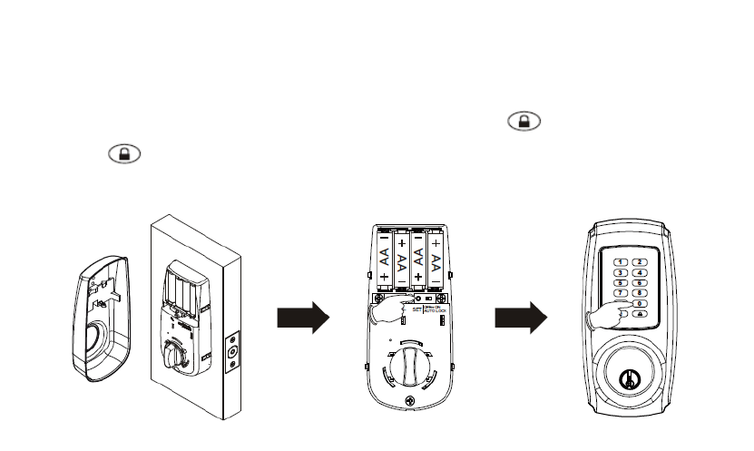
1. Remove one battery from the battery pack.
2. Press [SET] button and put the battery back simultaneously. The Green LED will light up and
beep twice. All functions will be restored back to factory setting.
Note:
1. All existing user codes and current programming code will be deleted.
2. Lock will be restored to pre-set programming code of 1-2-3-4-5-6.
3. Please change the programming code and add a new user code immediately before
operating the lockset.
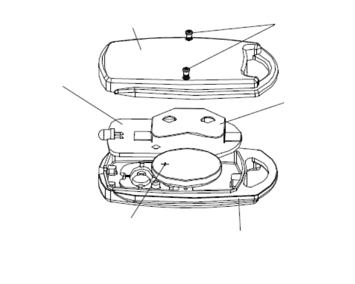
P41.
SETUP MODE
HOW TO REPLACE BATTERIES OF REMOTE CONTROL
Steps as following:
1. Loose two screws before opening the bottom shell.
2. Take the PCB out.
3. Push the battery out by inserting the tool into the crack between the PCB and the electrode
terminal.
4. Push into the new battery.
5. Replace the PCB.
6. Place the bottom shell back and tighten the screws.
Screws
Bottom shell
Front shell
Battery case
PCB
CR2032 Battery
(The carving side should face up and the
connecting point should face down)
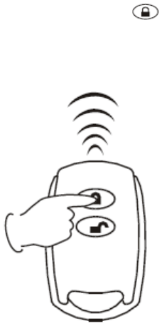
P42.
OPERATION MODE
HOW TO LOCK manually
Keypad: Press button to lock the door.
Remote control: Press lock button to lock the door as shown. (Only available for Remote Control
Electronic Deadbolt)
HOW TO LOCK automatically
1. Auto-lock mode should be turned on and auto-lock time delay should be also set up.
2. The lockset will be auto-locked in few seconds (default 10 seconds or the time you entered) after
unlocking by using codes, card, or remote control.

P43.
OPERATION MODE
HOW TO UNLOCK
1. Enter a valid code, put card to contact with the inductive zone, or press unlock button on the
remote control to unlock the lockset.
2. With double authorization mode is turned on, both user code and card, or both user code and
remote control, must be authenticated to unlock the lockset.
Note:
1. If you cannot unlock the lockset by using card, especially the lockset is mounted outside or
under the sun, please wakeup the lockset by pressing button on the keypad first, then
unlock the lockset by using card.
2. When you enter codes, the keypad backlight will also be activated automatically under
low-light environment.
3. Please press button to clear previous codes and re-enter codes if the previous codes are
incorrect.
4. If you do not press button to clear previous incorrect codes, the red LED will light up
and you have to wait until the red LED lights off, then the lockset is allowed to re-enter codes.

P44.
OPERATION MODE
SAFE MODE
1. The keypad will be automatically deactivated for 1 minute after 4 wrong attempts.
2. Wrong attempts will not be counted when you press button to clear previous incorrect
codes before the red LED lights up.
3. The deadbolt can be locked or unlocked by a valid traditional key under security.

P45.
TROUBLESHOOTING GUIDELINE
QUESTIONS ANSWERS
The lockset did not operate correctly after
installation.
1. Check center of strike hole for alignment
with latch hole on the door to ensure free
movement for the deadbolt.
2. Make sure the tailpiece is properly inserted
(in the horizontal position) in the latch.
3. Do [AUTOMATIC -BOLT DIRECTION
DETERMINATION].
Feel a bump while turning of the motor. 1. Please rotate the thumbturn back and forth
a few times.
Feel a bump while turning the thumbturn or
the key.
1. Please execute lock & unlock function to
allow the motor for repositioning again.
Keypad is not response at all. 1. Check to see if the batteries are
well-installed.
2. Check to see if the Yellow LED light is
flashing or not. It means "low battery" when
the light keeps flashing.
3. Make sure the cable is well-connected to
the port.
Programming code cannot be changed. 1. Please complete the "HOW TO CHANGE
PROGRAMMING CODE" process by
inputting codes within 10 seconds.
2. Please make sure you have entered the new
programming code twice correctly or go back
to the factory setting and reset the
programming code again.
I cannot delete all user codes. 1. Make sure all code inputting processes
should be completed within 10 seconds.
2. Make sure you have entered the correct
programming code.
3. button should be held over 3
seconds.
I cannot add a new user code. 1. Make sure all code inputting processes
should be completed within 10 seconds.
2. Make sure you have entered the correct
programming code.

3. The new user code will not be accepted if
10 sets of user codes are already stored in the
memory.
The lockset is not able to unlock by the
keypad
1. Make sure you have entered the correct
user code.
2. Check to see if the Yellow LED light is
flashing or not. It means "low battery" if the
light keeps flashing.
3. Please make sure the position of strike
plate is installed correctly if you see the latch
is jammed.
I am unable to reset the lockset. 1. Please refer to "HOW TO RESTORE
FACTORY SETTING” section and make
sure all steps are followed correctly.
2. Check to see if the Yellow LED light is
flashing or not. It means "low battery" if the
light keeps flashing.
Red LED light is still on after setting is
completed.
1. Please make sure if [SET] button is
jammed.
2. Please re-install the batteries.
"Auto lock" is malfunction. 1. Please make sure turn on auto-lock mode.
2. Check to see if the Yellow LED light is
flashing or not. It means "low battery" if the
light keeps flashing.
Yellow LED light keeps flashing. The battery is getting low, please reinstall all
new batteries for best performance (AA size
Alkaline batteries are only allowed).
What should I do if I input the wrong code? 1. Press button once and continue to
input code according to regular
procedures.
How to operate this lock under a dark
situation?
1. Press any button on the keypad to initiate
LED backlight.
Card or remote control is lost.
1. For your safety, please delete all cards/
remote controls and re-add current cards/
remote controls excluding the lost one.
Need more remote controls. 1. Please purchase the remote control
(produced by our company) from an
authorized retailer. Other remote controls

maybe not compatible with this lockset.
Need more proximity cards. 1. Proximity card we offer is the latest
Radio Frequency Identification (RFID)
technology, compatible with standard
Mifare -13.56 MHz.
2. You can use any card compatible with
standard Mifare -13.56 MHz or purchase
new cards from an authorized retailer.
What should I do if the lockset cannot be
unlocked by using card?
1. Make sure this card is stored in the
lockset.
2. Please press button first then use
card to unlock.
3. Please put card to contact with the
inductive zone to unlock.
If the lock appears to be damaged or does not function properly, please contact your local
provider for more help.
P49.
DECLARATIONS AND SAFETY STATEMENTS
Federal Communications Commission Statement
This device complies with Part 15 of the FCC. Operation is subject to the following two
conditions: (1) this device may not cause harmful interference, and (2) this device must accept any
interference received, including interference that may cause undesired operation.
Changes or modifications not expressly approved by the party responsible for compliance could
void the user‘s authority to operate the equipment.
NOTE:
This equipment has been tested and found to comply with the limits for a Class B digital device,
pursuant to part 15 of the FCC Rules. These limits are designed to provide reasonable protection
against harmful interference in a residential installation. This equipment generates, uses, and can
radiate radio frequency energy and, if not installed and used in accordance with the instructions, may
cause harmful interference to radio communications. However, there is no guarantee that interference
will not occur in a particular installation. If this equipment does cause harmful interference to radio or
television reception, which can be determined by turning the equipment off and on, the user is
encouraged to try to correct the interference by one or more of the following measures:
Reorient or relocate the receiving antenna.
Increase the separation between the equipment and receiver.
Connect the equipment into an outlet on a circuit different from that to which the receiver is
connected.
Consult the dealer or an experienced radio/TV technician for help.
IC Regulations
This Class B digital apparatus complies with Canadian ICES-003.
This device complies with Industry Canada licence-exempt RSS-210 standard. Operation is
subject to the following two conditions: (1) this device may not cause harmful interference, and (2) this
device must accept any interference received, including interference that may cause undesired
operation of the device.
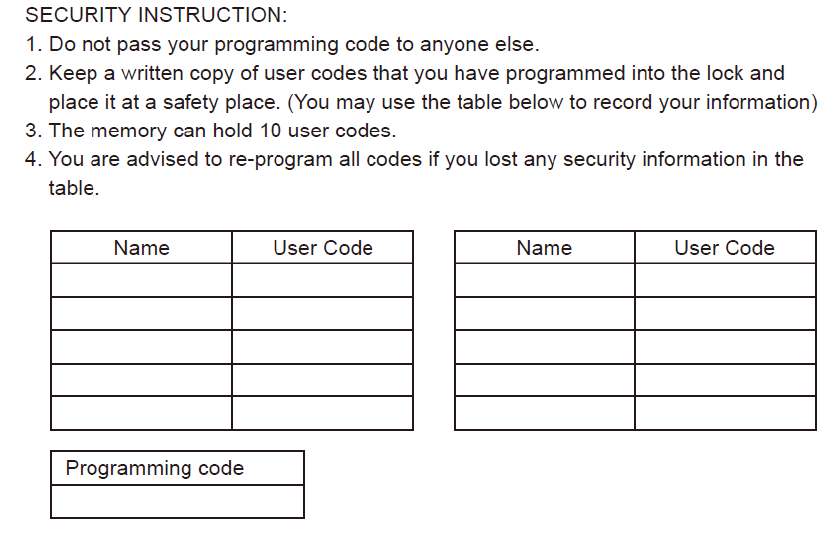
P50.
DATA RECORDS