Fuji Bikes Feh381 Users Manual FEH381_HARDWARE
UG230H-SS4x 2701fcfb-16f6-4677-8d66-77b9e9199e25
UG230H-SS4x to the manual 2701fcfb-16f6-4677-8d66-77b9e9199e25
2015-02-09
: Fuji-Bikes Fuji-Bikes-Feh381-Users-Manual-552547 fuji-bikes-feh381-users-manual-552547 fuji-bikes pdf
Open the PDF directly: View PDF ![]() .
.
Page Count: 124 [warning: Documents this large are best viewed by clicking the View PDF Link!]
- POD UG230 Series <Hardware> Cover (FEH381)
- Overview
- Specifications
- Installation
- Instructions
- Connections
- POD Operations
- Error Correction
- Inspection and Maintenance
- Back Cover

FUJI UG230 SERIES PROGRAMMABLE OPERATION DISPLAY
USER’S MANUAL <Hardware>
TYPE: UG230H-LS4x
UG230H-SS4x
UG230H-TS4x
FEH381
Create Tomorrow with
Trustworthy Technology
Preface
Thank you for selecting the Fuji Programmable Operation Display, POD UG230 Series (called as the UG230 or
POD hereafter).
This User’s Manual <UG230 Hardware> explains system configuration, specifications and handling of the UG230
Series. To enable you to fully utilize the display, carefully read this User’s Manual.
For more information on the UG230 Series, refer to the following manuals as well.
For further details about PLCs (programmable logic controllers), see the manual attached to each PLC.
Name Manual No. Contents
UG Series <Operation> FEH375 Describes operating procedures of the screen editor
(UG00S-CW) for the UG Series.
UG Series <Function> FEH376 Describes the functions available with the UG30/20
Series.
UG Series <PLC Connection> FEH380 Describes connections with PLCs, universal serial
communications, etc.
UG Series <Supplementary Manual> FEH376-1 Supplementary information for the UG Series
<Function>
UG Series <Tutorial> FEH350 Tutorial manual for novices in the UG Series
Notes:
1. This manual may not, in whole or in part, be printed or reproduced without the prior written consent of
Fuji Electric FA Components & Systems Co., Ltd.
2. The information in this manual is subject to change without prior notice.
3. Windows and Excel are registered trademarks of Microsoft Corporation in the United States and other
countries.
4. All other company names or product names are trademarks or registered trademarks of their
respective holders.
5. This manual is intended to give accurate information about POD hardware. If you have any
questions, please contact your local distributor.

Record of Revisions
Reference numbers are shown at the bottom left corner on the back cover of each manual.
Printing Date Reference No. Revised Contents
February, 2004 FEH381 First edition
Notes on Safe Use of POD
In this manual, you will find various notes categorized under the following levels with the signal words “DANGER,”
and “CAUTION.”
Note that there is a possibility that the item listed with may have serious ramifications.
DANGER Indicates an imminently hazardous situation which, if not avoided, will result in death or
serious injury.
CAUTION
Indicates a potentially hazardous situation which, if not avoided, may result in minor or
moderate injury and could cause property damage.
•Never use the input function of POD for operations that may threaten human life or to damage the system,
such as switches to be used in case of emergency. Please design the system so that it can cope with
malfunction of a touch switch. A malfunction of the touch switch will result in machine accident or damage.
•Turn off the power supply when you set up the unit, connect cables or perform maintenance and inspection.
Otherwise, electrical shock or damage may occur.
•Never touch any terminals while the power is on. Otherwise, electric shock may occur.
•You must put a cover on the terminals on the unit when you turn the power on and operate the unit. Without
the terminal cover in place, an electric shock may occur.
•The liquid crystal in the LCD panel is a hazardous substance. If the LCD panel is damaged, never swallow
the leaked liquid crystal. If the liquid crystal spills on your skin or clothing, use soap and wash off thoroughly.
•For POD using a lithium battery, never disassemble, recharge, deform by pressure, short-circuit, nor reverse
the polarity of the battery, and never dispose of the battery in fire. Failure to follow these conditions will lead
to explosion or ignition.
•For POD using a lithium battery, never use a battery that is deformed, leaks, or shows any other signs of
abnormality. Failure to follow these conditions will lead to explosion or ignition.
CAUTION
DANGER

•Check the appearance of the unit when it is unpacked. Do not use the unit if any damage or deformation is
found. Failure to do so may lead to fire, damage or malfunction.
•For use in a facility or for a system related to nuclear energy, aerospace, medical, traffic equipment, or
mobile installations, please consult your local distributor.
•Operate (or store) POD under the conditions indicated in this manual and related manuals. Failure to do so
could cause fire, malfunction, physical damage or deterioration.
•Understand the following environmental limits for use and storage of POD. Otherwise, fire or damage to the
unit may result.
- Avoid locations where there is a possibility that water, corrosive gas, flammable gas, solvents, grinding
fluids or cutting oil can come into contact with the unit.
- Avoid high temperature, high humidity, and outside weather conditions, such as wind, rain or direct
sunlight.
- Avoid locations where excessive dust, salt, and metallic particles are present.
- Avoid installing the unit in a location where vibration or physical shock may be transmitted.
•Equipment must be correctly mounted so that the main terminal of POD will not be touched inadvertently.
Otherwise, an accident or electric shock may occur.
•Tighten the fixtures of the POD with a torque in the specified range. Excessive tightening may distort the
panel surface. Loose tightening may cause POD to come off, malfunction or be short-circuited.
•Check periodically that terminal screws on the power supply terminal block and fixtures are firmly tightened.
Loosened screws may result in fire or malfunction.
•Tighten terminal screws on the power supply terminal block equally to a torque of 0.5 N•m. Improper
tightening of screws may result in fire, malfunction, or trouble.
•POD has a glass screen. Do not drop or give physical shock to the unit. Otherwise, the screen may be
damaged.
•Connect the cables correctly to the terminals of POD in accordance with the specified voltage and wattage.
Over-voltage, over-wattage or incorrect cable connection could cause fire, malfunction or damage to the
unit.
•Be sure to establish a ground of POD. Ground FG terminal which must be used for the unit. Otherwise,
electric shock or a fire may occur.
•Prevent any conductive particles from entering into POD. Failure to do so may lead to fire, damage or
malfunction.
•After wiring is finished, remove the paper used as a dust cover before starting to operate POD. Operation
with the cover attached may result in accident, fire, malfunction, or trouble.
•Do not attempt to repair POD at your site. Ask us or the designated contractor for repair.
•Do not disassemble or modify POD. Otherwise, it may cause a malfunction.
•Fuji Electric FA Components & Systems Co., Ltd. is not responsible for any damages resulting from repair,
overhaul or modification of POD that was performed by an unauthorized person.
•Do not use a sharp-pointed tool when pressing a touch switch. Doing so may damage the screen.
•Only experts are authorized to set up the unit, connect the cables or perform maintenance and inspection.
•For POD using a lithium battery, handle the battery with care. The combustible materials such as lithium or
organic solvent contained in the battery may generate heat, explode, or catch fire, resulting in personal injury
or fire. Read related manuals carefully and handle the lithium battery correctly as instructed.
•When using a POD that has analog switch resolution with resistance film, do not press two or more points on
the screen at the same time. If there is a switch between the two pressed points, it may be activated.
•Take safety precautions during such operations as setting change during running, forced output, start, and
stop. Any misoperation may cause unexpected machine motions, resulting in machine accident or damage.
•In facilities where a failure of POD could lead to accident threatening human life or other serious damage, be
sure that the facilities are equipped with adequate safeguards.
•At the time of disposal, POD must be treated as industrial waste.
•Before touching POD, discharge static electricity from your body by touching grounded metal. Excessive
static electricity may cause malfunction or trouble.
CAUTION

[General Notes]
•Never bundle control cables and input/output cables with high-voltage and large-current carrying cables such
as power supply cables. Keep these cables at least 200 mm away from the high-voltage and large-current
carrying cables. Otherwise, malfunction may occur due to noise.
•Plug connectors or sockets of POD in the correct orientation. Otherwise, it may cause a malfunction.
•Do not use thinners for cleaning because they may discolor the POD surface. Use alcohol or benzine
commercially available.
•If a data receive error occurs when POD and the counterpart (PLC, temperature controller, etc.) are started at
the same time, read the manual for the counterpart unit and handle the error correctly.
•Avoid discharging static electricity on the mounting panel of the POD. Static charges can damage the unit and
cause malfunctions. Otherwise, malfunction may occur due to noise.
•Avoid prolonged display of any fixed pattern. Due to the characteristics of the liquid crystal display, an
afterimage may occur. If a prolonged display of a fixed pattern is expected, use the auto OFF function of the
backlight.

Contents
Preface
Notes on Safe Use of POD
Chapter 1 Overview
1. Features............................................................................................................................................ 1-1
2. Models and Peripheral Equipment.................................................................................................... 1-2
POD Models........................................................................................................................................................1-2
Peripheral Equipment..........................................................................................................................................1-3
3. System Composition ......................................................................................................................... 1-6
System Composition of UG230...........................................................................................................................1-6
System Composition of UG230 + UG230A-DCL.................................................................................................1-7
Chapter 2 Specifications
1. Specifications.................................................................................................................................... 2-1
General Specifications ........................................................................................................................................2-1
Display Specifications .........................................................................................................................................2-2
Touch Switch Specifications ...............................................................................................................................2-2
Function Switch Specifications............................................................................................................................2-2
Interface Specifications .......................................................................................................................................2-3
Clock and Backup Memory Specifications ..........................................................................................................2-3
Drawing Environment ..........................................................................................................................................2-3
Display Function Specifications ..........................................................................................................................2-4
Function Performance Specifications..................................................................................................................2-5
2. Dimensions and Panel Cut-out ......................................................................................................... 2-6
UG230 External View and Dimensions ...............................................................................................................2-6
UG230 + UG230A-DCL External View and Dimensions.....................................................................................2-7
3. Names and Functions of Components.............................................................................................. 2-8
4. Modular Jack (MJ1/MJ2)................................................................................................................. 2-10
Modular Jack 1 (MJ1)........................................................................................................................................2-10
Modular Jack 2 (MJ2: Exclusive to the UG230) ................................................................................................2-11
Notes on Wiring.................................................................................................................................................2-14
Transferring Screen Data ..................................................................................................................................2-17
Barcode Reader Connection.............................................................................................................................2-17
Printer Connection (Serial Printer) ....................................................................................................................2-18
5. USB Connectors ............................................................................................................................. 2-19
USB-A (Master Port) .........................................................................................................................................2-19
USB-B (Slave Port) ...........................................................................................................................................2-20
6. D-sub 25-Pin Connector (CN1) (Optional) ...................................................................................... 2-25
Serial Connector (CN1) .....................................................................................................................................2-25
7. 10BASE-T (LAN) (Optional)............................................................................................................ 2-26
10BASE-T Connector........................................................................................................................................2-26
Notes on Wiring.................................................................................................................................................2-27
8. CF Card .......................................................................................................................................... 2-28
Recommended CF Cards .................................................................................................................................2-28
CF Card Insertion Position ................................................................................................................................2-28
Mounting and Dismounting the CF Card...........................................................................................................2-29
Notes on Handling the CF Card ........................................................................................................................2-30

Chapter 3 Installation
1. Mounting Procedure.......................................................................................................................... 3-1
Mounting Procedure............................................................................................................................................3-1
Mounting Angle ...................................................................................................................................................3-1
2. Power Supply Cable Connection ...................................................................................................... 3-2
Power Supply Cable Connection ........................................................................................................................3-2
Grounding ...........................................................................................................................................................3-3
Chapter 4 Instructions
1. Coin-type Lithium Battery.................................................................................................................. 4-1
Battery Mounting Procedure ...............................................................................................................................4-1
Battery Replacement ..........................................................................................................................................4-2
2. DIP Switch Setting ............................................................................................................................ 4-4
DIP Switch (DIPSW) Setting ...............................................................................................................................4-4
3. Function Switches ............................................................................................................................. 4-5
Types ..................................................................................................................................................................4-5
[SYSTEM] Switch................................................................................................................................................4-5
Chapter 5 Connections
1. 1 : 1 Connection ................................................................................................................................ 5-1
2. 1 : n Connection (Multi-drop)............................................................................................................. 5-2
3. n : 1 Connection (Multi-link 2) ........................................................................................................... 5-3
4. n : 1 Connection (Multi-link) .............................................................................................................. 5-4
5. Universal Serial Communications ..................................................................................................... 5-5
6. UG-Link ............................................................................................................................................. 5-6
7. PLC2Way .......................................................................................................................................... 5-7
8. Temperature Control Network........................................................................................................... 5-8
9. Ethernet............................................................................................................................................. 5-9
Chapter 6 POD Operations
1. Operational Procedures .................................................................................................................... 6-1
POD Operation ...................................................................................................................................................6-1
2. Main Menu Screen ............................................................................................................................ 6-4
Displaying the Main Menu Screen ......................................................................................................................6-4
Moving Back to the Screen in the RUN Mode ....................................................................................................6-4
Main Menu Screen..............................................................................................................................................6-5
1. I/O Test ............................................................................................................................... 6-5
1-1. USB Test................................................................................................................... 6-6
1-2. Serial Connection Test.............................................................................................. 6-7
1-3. SYSTEM & Function Switch Test ........................................................................... 6-13
1-4. Touch Switch Test .................................................................................................. 6-13
2. Card Menu Screen ............................................................................................................ 6-15
2-1. Card Recorder Menu Screen .................................................................................. 6-16
2-2. Transferring Screen Data from a CF Card.............................................................. 6-18
2-3. Saving Backup Copies of SRAM ............................................................................ 6-24
2-4. Messages during Data Transfer.............................................................................. 6-26
3. Communication Parameter Screen................................................................................... 6-27

4. Extension Program Information ........................................................................................ 6-28
5. Ethernet (Optional)............................................................................................................ 6-29
5-1. Ethernet Information Screen................................................................................... 6-29
5-2. IP Address Setting .................................................................................................. 6-30
6. SRAM/Clock...................................................................................................................... 6-36
7. Extended Function Setting................................................................................................ 6-38
Chapter 7 Error Correction
1. Error Messages................................................................................................................................. 7-1
1. Communication Error .......................................................................................................... 7-1
2. Check.................................................................................................................................. 7-3
3. Warning............................................................................................................................... 7-3
4. SYSTEM ERROR ............................................................................................................... 7-4
5. Touch Switch is Active ........................................................................................................7-4
2. Troubleshooting ................................................................................................................................ 7-5
In the Event of an Error .......................................................................................................................................7-5
Probable Symptoms ............................................................................................................................................7-5
Chapter 8 Inspection and Maintenance
1. Inspection and Maintenance ............................................................................................................. 8-1
Daily Inspection ...................................................................................................................................................8-1
Periodical Inspection ...........................................................................................................................................8-1
2. Warranty Policy................................................................................................................................. 8-2
Inquiries about Failure.........................................................................................................................................8-2
Warranty Period ..................................................................................................................................................8-2
Free-of-charge Repair.........................................................................................................................................8-2
Chargeable Repair ..............................................................................................................................................8-2


1
1. Features 1-1
Overview
1. Features
The UG230 series inherits and heightens the features of the UG20 series as described below.
1. 32k-color Display (except for UG230H-LS4x)
32,768-color display makes colorful expression possible.
JPEG files and bitmap files are clearly displayed in brilliant colors.
2. USB Master/Slave Port as Standard
Two ports are provided as standard for diverse applications.
At the master port, a USB-compatible EPSON STYLUS PHOTO series printer or CF card
reader/writer can be used.
On-site versatility is extended further.
At the slave port, large quantities screen data can be transferred from the computer at a high
speed.
3. SRAM and Clock Function as Standard
A 128 kbyte SRAM is standard, allowing backup copies of recipe data or sampling data to be
saved with ease.
4. CF Card Interface Supported (USB master port/optional)
The CF card can be used for saving multiple screen data, sampling data, recipe data, hard copy
images, and other various usages.
JPEG files and font files can also be saved.
5. 10BASE-T Connector Supported (optional)
This connector enables Ethernet connection with a host computer or PLC.
High-speed communications are possible via Ethernet for transferring screen data and
reading/writing data from/to the server.
6. Analog Switch/Matrix Switch Supported
The switch type can be selected from the lineup according to your application.
A variety of switch types is available to suit your requirements.
1-2 2. Models and Peripheral Equipment
2. Models and Peripheral Equipment
POD Models
The model name consists of the following information.
The following models are available.
UG 2 30 H - L S 4 D
Touch switch specification
None: Analog switch
D: Matrix switch
Power supply specification
4: 24 VDC specification
(in compliance with CE/UL/cUL)
Functional specification
S: Standard
Device specification
T: TFT color LCD (QVGA)
S: STN color LCD (QVGA)
L: STN monochrome LCD (QVGA)
Screen size
2: 5.7-inch
Version information
POD unit type
Series and Size Model Name Specifications Remarks
UG230 series
5.7-inch
UG230H-TS4 TFT color, 320 × 240 dots, analog switch
DC power supply
Compliant with
CE/UL/cUL
UG230H-TS4D TFT color, 320 × 240 dots, matrix switch
DC power supply
Compliant with
CE/UL/cUL
UG230H-SS4 STN color, 320 × 240 dots, analog switch
DC power supply
Compliant with
CE/UL/cUL
UG230H-SS4D STN color, 320 × 240 dots, matrix switch
DC power supply
Compliant with
CE/UL/cUL
UG230H-LS4 STN monochrome, 320 × 240 dots, analog switch
DC power supply
Compliant with
CE/UL/cUL
UG230H-LS4D STN monochrome, 320 × 240 dots, matrix switch
DC power supply
Compliant with
CE/UL/cUL
1
2. Models and Peripheral Equipment 1-3
Overview
Peripheral Equipment
The following options are available for using the UG230 series more effectively.
UG00S-CWV3 (configuration software: English/Japanese)
Application software for editing display data for the POD.
(Windows98/NT4.0/Me/2000/XP compatible)
The UG230 series is supported with ver. 3.2.0.0 and later.
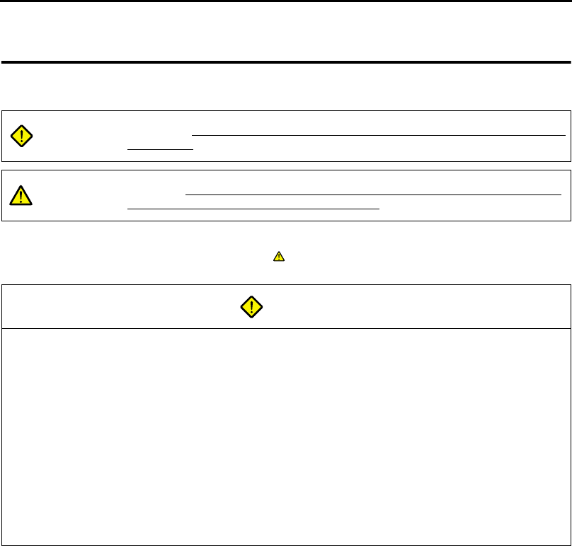
UG230A-DCL (option unit)
Optional unit to be used for D-sub 25-pin connector, CF card and Ethernet.
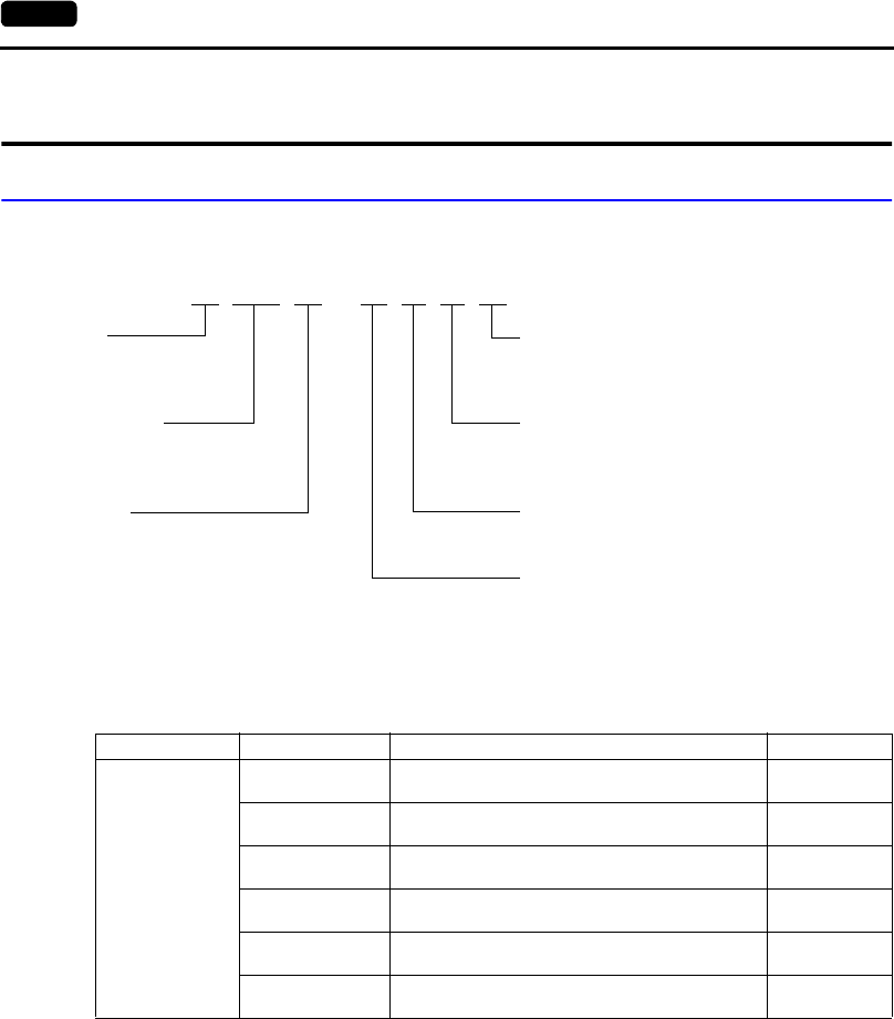
UG230P-D4 (FLASH memory cassette)
Extension print circuit board to extend the memory for screen data.
The capacity of FLASH memory is 4 Mbyte.
* Only when the UG230A-DCL (option unit) is provided
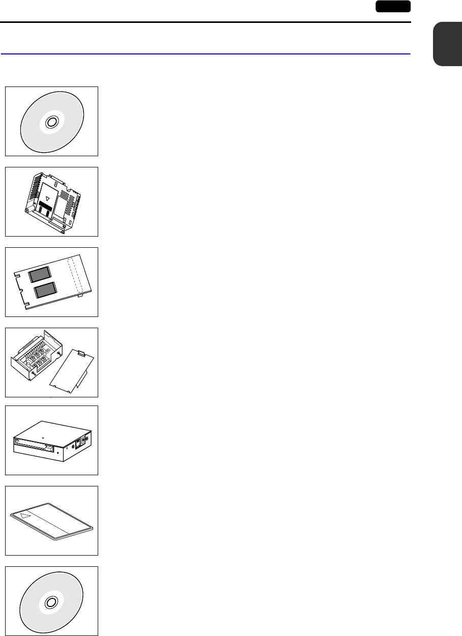
UG00P-TC (terminal converter)
Used for connection between the UG30 series and a PLC at the RS-422/485 terminal block.
* Only when the UG230A-DCL (option unit) is provided
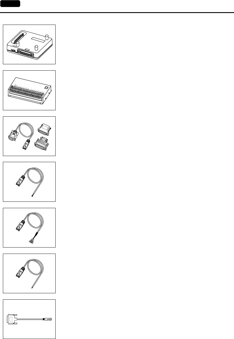
UG00P-MR (card recorder)
The card recorder creates a backup copy of screen data or works as an external memory
storage system for memory manager and data logging functions.
UG00K-xx (memory card) compliant with JEIDA ver. 4.0
Used with the card recorder when having a backup copy of screen data or saving data on an
external medium for memory manager and data logging functions.
SRAM 256 K, 512 K, 1 M, 2 M, 4 Mbyte
FLASH ROM 256 K, 512 K, 1 Mbyte
UG00P-MS (memory card editor: English/Japanese)
Application software for editing data stored on a memory card, SRAM or CF card.
(Windows98/NT4.0/Me/2000/XP compatible)
TB1
SW1
CN1
1-4 2. Models and Peripheral Equipment
UG00P-DI (ACPU/QnACPU/FXCPU dual port interface)
Add-on connector with two ports, specifically designed for the connector on the
MITSUBISHI’s ACPU/QnACPU/FXCPU programmer. Operability can be improved when
directly connecting the POD to the ACPU/QnACPU/FXCPU programmer.
* Only when the UG230A-DCL (option unit) is provided
UG00P-U2 (serial extension I/O)
Used as an external I/O unit for PLC. It has 16 inputs and 16 outputs.
UG00C-T (screen data transfer cable) 3 m
Used for connection between the POD and a personal computer, or a personal computer
and the card recorder (UG00P-MR).
UG00C-B (barcode reader connection cable) 3 m
Used for connection between the POD and a barcode reader.
This is also used for connection between the POD and a temperature controller via
RS-232C.
UG00C-H (multi-link 2 master cable/temperature controller connection cable) 3 m
Used for Multi-Link 2 connection between the POD master station and the POD slave
station.
This is also used for connection between the POD and a temperature controller via RS-422
(485).
UG00C-P (temperature controller connection cable) 3 m
Used for connection between the POD and a temperature controller or a PLC using the
PLC2Way function via RS-422 (4-wire connection).
This is also used for connection with a PLC at the MJ2 port on the UG230.
UG30C-J (MJ2-to-D-sub conversion cable) 0.3 m
Used for connection between the UG230 and a PLC at MJ2.
GD
GPP
1 2 3
FGI
N0IN2IN4
IN6IN8
IN10IN12IN14COM+
OUT0
IN1IN3IN5IN7IN9IN11IN13IN15
OUT2OUT4OUT6COM1OUT9OUT11OUT13OUT15
OUT1OUT3OUT5OUT7OUT8OUT10OUT12OUT14COM2
DC24V
MJ1
1
2. Models and Peripheral Equipment 1-5
Overview
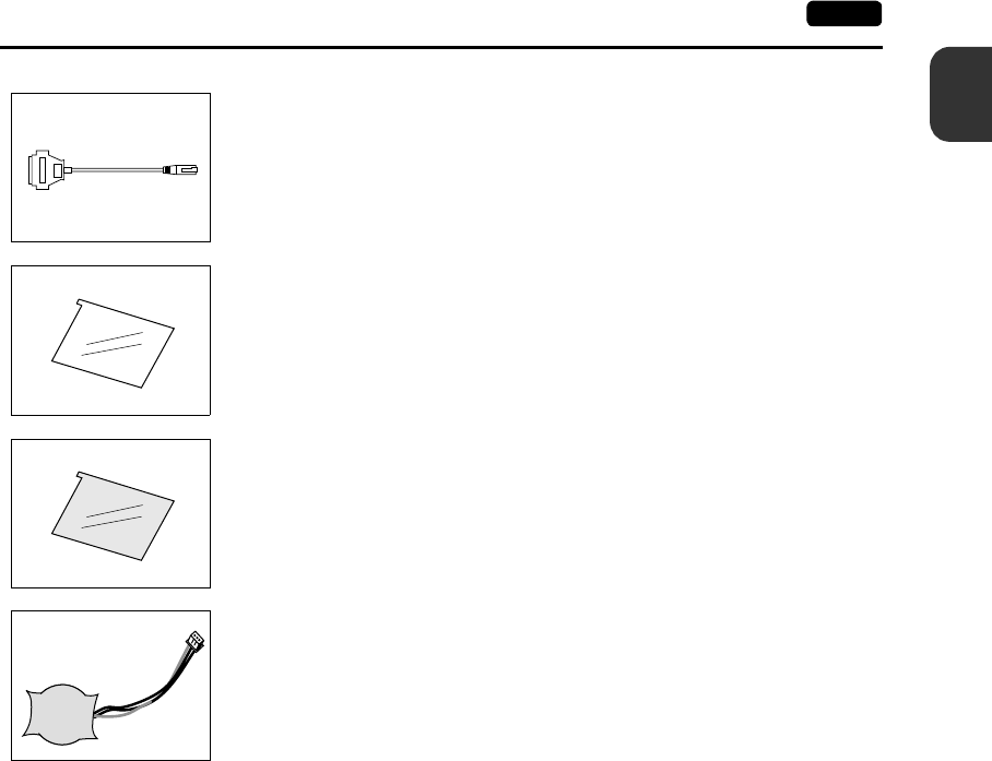
UG30C-M (MJ-to-D-sub conversion cable) 0.3 m
Used for connection of the POD via PLC2Way.
UGxxP-PS (protective sheet)
This sheet protects the operation panel surface. (5 sheets/set)
UGxxP-PT (protective sheet)
This anti-glare sheet protects the operation panel surface. (5 sheets/set)
UG30P-BT (battery for replacement)
Replacement lithium battery for the UG30 series.
1-6 3. System Composition
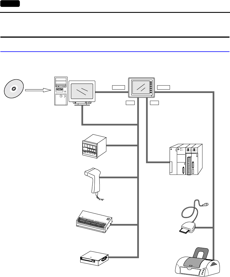
3. System Composition
System Composition of UG230
The following illustration shows possible system configurations using the UG230.
RESET
disc
UG00S-CW
RS-232C/RS-422
UG00C-T
UG230
USB-B
UG00P-MR
UG00C-B
UG00C-P
FGIN0IN2IN4
IN6IN8
IN10IN12IN14COM+
OUT0
IN1IN3IN5IN7IN9IN11IN13IN15
OUT2OUT4OUT6COM1OUT9OUT11OUT13OUT15
OUT1OUT3OUT5OUT7OUT8OUT10O
UT12OUT14COM2
DC24V
MJ1
UG00P-U2
USB-A
MJ2MJ1
C F R W
96
MB
Computer (PC)
(USB master)
During operation
(Link/universal serial communication)
UG series
configuration
software
Creating screens
CF card
reader/writer
Link unit/
general-purpose computer
Transferring
screen data
Card recorder
Printer
Barcode reader
Temperature controller,
inverter
(USB slave)
1
3. System Composition 1-7
Overview
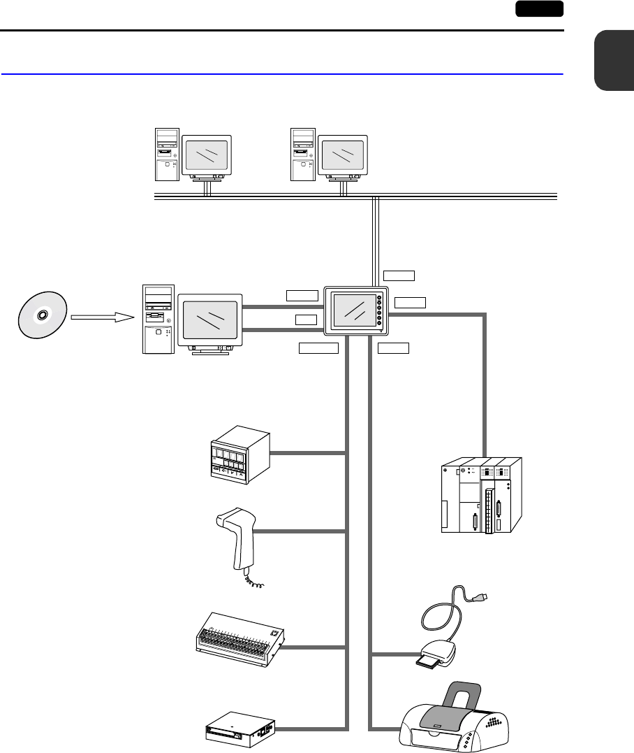
System Composition of UG230 + UG230A-DCL
The following illustration shows possible system configurations using the UG230 and the
UG230A-DCL.
RESET
disc
UG00S-CW
RS-232C/RS-422
UG00C-T
UG230+UG230A-DCL
USB-B
UG00P-MR
UG00C-B
UG00C-P
FGIN0IN2IN4
IN6IN8
IN10IN12IN14COM+
OUT0
IN1IN3IN5IN7IN9IN11IN13IN15
OUT2OUT4OUT6COM1OUT9OUT11OUT13OUT15
OUT1OUT3OUT5OUT7OUT8OUT10O
UT12OUT14COM2
DC24V
MJ1
UG00P-U2
USB-AMJ1/MJ2
MJ1
C F R W
96
MB
RESET
disc
RESET
disc
LAN
D-sub
Ethernet
Computer (PC) (USB master)
During operation
(Link/universal serial
communication)
UG series
configuration
software
Creating screens
CF card
reader/writer
Link unit/
general-purpose computer
Transferring
screen data
Card recorder
Printer
Barcode reader
Temperature controller,
inverter
(USB slave)
Computer (PC) Computer (PC)

1-8 3. System Composition
Please use this page freely.

2
1. Specifications 2-1
Specifications
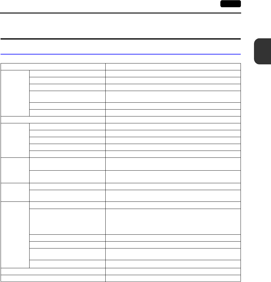
1. Specifications
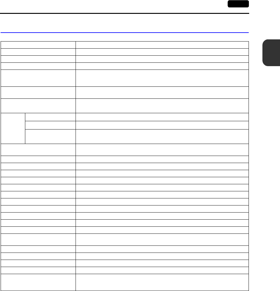
General Specifications
* As for UG230H-SS4x and UG230H-LS4x, operation for long hours at ambient temperatures of 40 to 50°C may
degrade the display quality, such as lowering contrast.
Item Specifications
Power
Supply
Rated Voltage 24 VDC
Permissible Range of Voltage 24 VDC ± 10%
Permissible Momentary Power Failure Within 1 ms
Power Consumption
(Maximum Rating) 16 W or less
Rush Current 20 A or less (with a rise time 0.1 ms)
Withstand Voltage DC external terminals to FG: 500 VAC, 1 minute
Insulation Resistance 500 VDC, 10 MΩ or above
Physical
Environment
Ambient Temperature 0°C to +50°C *
Storage Ambient Temperature −10°C to +60°C
Ambient Humidity 85% RH or less (without dew condensation)
Solvent Resistance No cutting oil or organic solvent attached to the unit
Atmosphere No corrosive gas or conductive dust
Mechanical
Working
Conditions
Vibration Resistance Vibration frequency: 10 to 150 Hz, Acceleration: 9.8 m/s2
Single amplitude: 0.075 mm, X, Y, Z: 3 directions for one hour
Shock Resistance Pulse shape: Sine half wave
Peak acceleration: 147 m/s2, X, Y, Z: 3 directions six times each
Electrical
Working
Conditions
Noise Resistance 1000 Vp-p (pulse width 1µs, rise time: 1 ns)
Static Electricity Discharge Resistance Compliant with IEC61000-4-2,
contact: 6 kV, air: 8 kV
Mounting
Conditions
Grounding Grounding resistance: less than 100 Ω
Structure
Protection structure: Front panel: compliant with IP65 (when using
waterproof gasket)
Rear case: compliant with IP20
Form: In a single body
Mounting procedure: Inserted in a mounting panel
Cooling System Cooling naturally
Weight Unit only: approx. 680 g, with UG230A-DCL installed: approx. 820 g
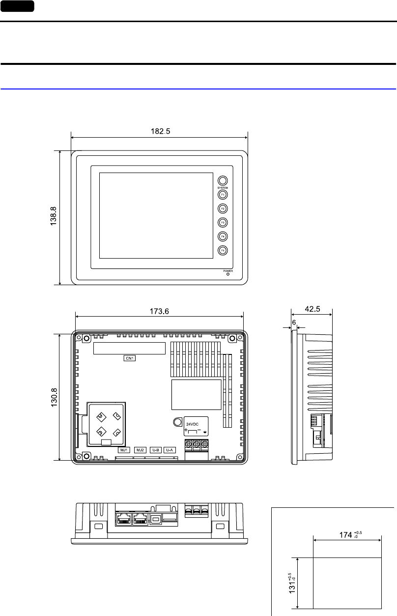
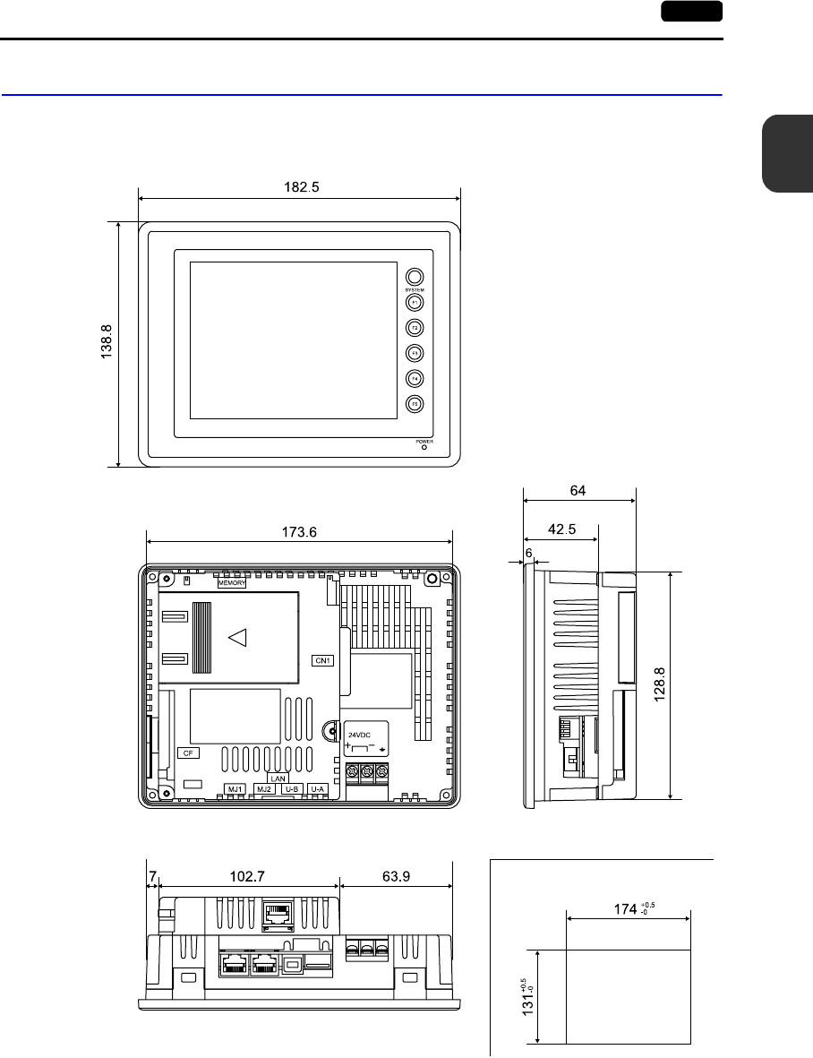
External Dimensions W × H × D (mm) Unit only: 182.5 × 138.8 × 42.5,
with UG230A-DCL installed: 182.5 × 138.8 × 64.0
Panel Cut-out Dimensions (mm) 174 × 131
Case Color Black (Munsell N2.0)
Material PC/PS resin (Tarflon)
+0.5
−0
+0.5
−0
2-2 1. Specifications
Display Specifications
*1 When the normal temperature is 25°C, and the surface luminance of the display is 50% of the initial
setting
*2 Adjustable with function switches
*3 By using the macro command
Touch Switch Specifications
Function Switch Specifications
Item Model
UG230H-TS4x UG230H-SS4x UG230H-LS4x
Display Device TFT color LCD STN color LCD STN monochrome LCD
Display Size 5.7-inch
Colors 32,768 colors
+16-color blinks
Monochrome 8-grade
+ blink
Resolution W × H (dots) 320 × 240
Dot Pitch W × H (mm) 0.36 × 0.36 0.36 × 0.36 0.36 × 0.36
Brightness (cd/m2)350 160 220
Contrast Ratio 60 : 1 30 : 1 5 : 1
Angle of Vertical Visibility (°) +65, −40 +20, −35 +20, −40
Angle of Horizontal Visibility (°)±65 ±50 ±45
Backlight Cold cathode rectifier (cannot be replaced by users)
Average Backlight Life*1 Approx. 50,000 h Approx. 54,000 h Approx. 58,000 h
Backlight Auto OFF Function Always ON, random setting
Contrast Adjustment Not provided Provided *2
Brightness Adjustment 128 levels *3 Not provided
Surface Sheet Material: Polycarbonate, 0.3 mm thick
POWER Lamp
Illuminated in green when the power is on;
illuminated in orange when the voltage of the battery (with its cable connected) has
become low.
MJ2 Function Selection Slide switch Down: RS-422 (4-wire)
Up: RS-232C
Item Specifications
Method Analog resistance film type, matrix resistance film type
Switch Resolution Analog: 1024 (W) × 1024 (H)
Matrix: 20 (W) × 12 (H)
Mechanical Life One million activations or more
Surface Treatment Hard-coated, anti-glare treatment 5%
Item Specifications
Number of Switches 6
Method Digital resistance film
Mechanical Life One million activations or more
2
1. Specifications 2-3
Specifications
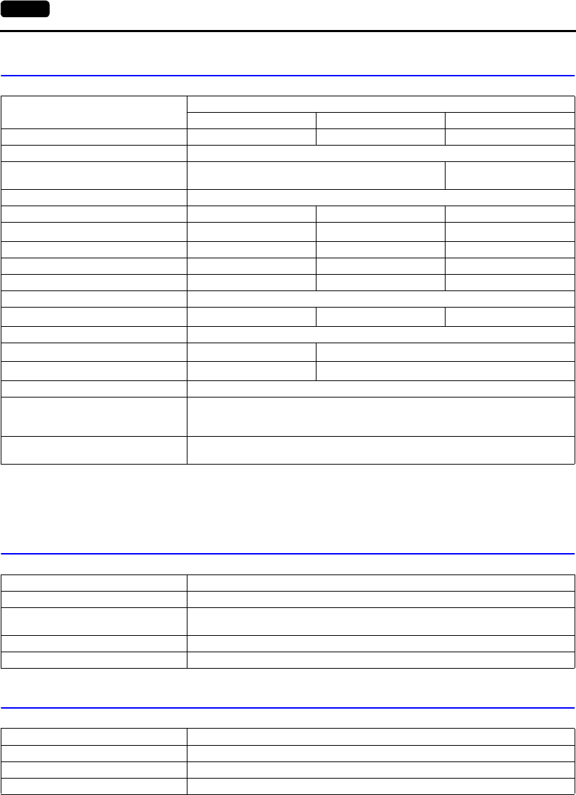
Interface Specifications
Clock and Backup Memory Specifications
Drawing Environment
Item Specifications
Screen Data Transfer/External
Connection
Serial Interface
(Modular jack, 8-pin: MJ1)
RS-232C, RS-422/485 (2-wire connection)
UG00P-MR, Barcode, UG00P-U2, Multi-link 2,
Temperature control network/PLC2Way, UG-link, etc.
PLC Connection
Serial Interface
(Modular jack, 8-pin: MJ2)
RS-232C, RS-422 (4-wire connection)
Asynchronous type
Data length: 7, 8 bits
Parity: Even, odd, none
Stop bit: 1, 2 bits
Baud Rate: 4800, 9600, 19200, 38400, 57600, 76800, 115200 bps
Printer/CF Card Reader Connection
USB Master Port (USB-A) Type A, USB Ver. 1.1
Screen Data Transfer
USB Slave Port (USB-B) Type B, USB Ver. 1.1
Item Specifications
Battery Specification Coin-type lithium primary cell
Backup Memory SRAM 128 kbyte
Backup Time Period 5 years (ambient temperature at 25°C)
Battery Voltage Drop Detection Provided (internal memory allocated)
Calendar Accuracy Monthly deviation ±90 sec (ambient temperature at 25°C)
Item Specifications
Drawing Method Exclusive drawing software
Drawing Tool
Name of exclusive configuration software: UG00S-CW (Ver. 3.2.0.0 and later)
Personal computer: Pentium II 450 MHz or above
recommended
OS: Windows98/Me/NT Ver.4.0/2000/XP
Capacity of hard disk required: Free space of approx. 460 Mbyte or more
(For minimum installation:
approx. 105 Mbyte)
Display: Resolution 800 × 600 or above
recommended
2-4 1. Specifications
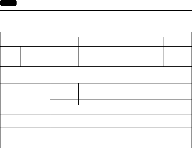
Display Function Specifications
* In addition, the following fonts are available. For more information, refer to the User’s Manual <Operation>
(FEH375) and the User’s Manual <Supplementary Manual> (FEH376-1).
Gothic, English/Western Europe (HK Gothic), English/Western Europe (HK Times), Central Europe, Cyrillic,
Greek, Turkish
Item Specifications
Display Language* USEnglish English/Western
Europe
Chinese
(traditional)
Chinese
(simplified) Korean
Characters
1/4-size, 1-byte ANK code Latin1 ASCII code ASCII code ASCII code
2-byte 16-dot JIS #1, 2 levels −Chinese
(traditional)
Chinese
(simplified)
Hangul
(without Kanji)
2-byte 32-dot JIS #1 level −−−−
Character Size
1/4-size: 8 × 8 dots
1-byte: 8 × 16 dots
2-byte: 16 × 16 dots or 32 × 32 dots
Enlarge: W: 1 to 8 times, H: 1 to 8 times
Number of Displayable
Characters
Resolution 320 × 240
1/4-size 40 characters × 30 lines
1-byte 40 characters × 15 lines
2-byte 20 characters × 15 lines
Characters Properties Display properties: Normal, reverse, blink, bold, shadow
Colors: 32,768 colors + blink 16 colors / monochrome 8-grade + blink
Graphics
Lines: Line, continuous line, box, parallelogram, polygon
Circles: Circle, arc, sector, ellipse, elliptical arc
Others: Tile patterns
Graphic Properties
Line types: 6 (thin, thick, dot, chain, broken, two-dot chain)
Tile patterns: 16 (incl. user-definable 8 patterns)
Display properties: Normal, reverse, blink
Colors: 32,768 colors + blink 16 colors / monochrome 8-grade + blink
Color selection: Foreground, background, boundary (line)
2
1. Specifications 2-5
Specifications
Function Performance Specifications
*1 The number of setting memory locations is limited to 256 per screen.
*2 Layer: 4 per screen (base + 3 overlaps)
Item Specifications
Screens Max. 1024
Screen Memory Flash memory: Appox. 1,472 kbyte (varies depending on the font)
Switches 192 per screen
Switch Actions
Set, reset, momentary, alternate, to light
(Possible to press a function switch and a switch on the display at the same time)
(Matrix type: Possible to press two switches on the display at the same time)
Lamps Reverse, blink, exchange of graphics
192 per screen
Graphs Pie, bar, panel meter and closed area graph: No limitation within 256 kbyte per screen*1
Statistics and trend graphs: Max. 256 per layer*2
Data
Setting
Numerical Data Display No limitation within 256 kbyte per screen*1
Character Display No limitation within 256 kbyte per screen*1
Message Display Resolution: Max. 40 1-byte characters
No limitation within 256 kbyte per screen*1
Sampling Sampling display of buffer data
(Constant sample, bit synchronize, bit sample, relay sample, alarm function)
Graphic Library Max. 2560
Multi-Overlaps Max. 1024
Data Blocks Max. 1024
Messages Max. 6144 lines
Patterns Max. 1024
Macro Blocks Max. 1024
Page Blocks Max. 1024
Direct Blocks Max. 1024
Screen Blocks Max. 1024
Data Sheets Max. 1024
Screen Library Max. 1024
Temperature Control Network/
PLC2Way Table Max. 32
Time Display Time display function: provided
Hard Copy Screen hard copy function: provided
Buzzer Buzzer: provided, 2 sounds (short beep, long beep)
Auto OFF Function Always ON, random setting
Self-diagnostic Function
Switch self-test function
Communication parameter setting check function
Communication check function
2-6 2. Dimensions and Panel Cut-out
2. Dimensions and Panel Cut-out
UG230 External View and Dimensions
(Unit: mm)
•Side View
•Front View
•Panel Cut-out Dimensions
•Rear View
•Bottom View
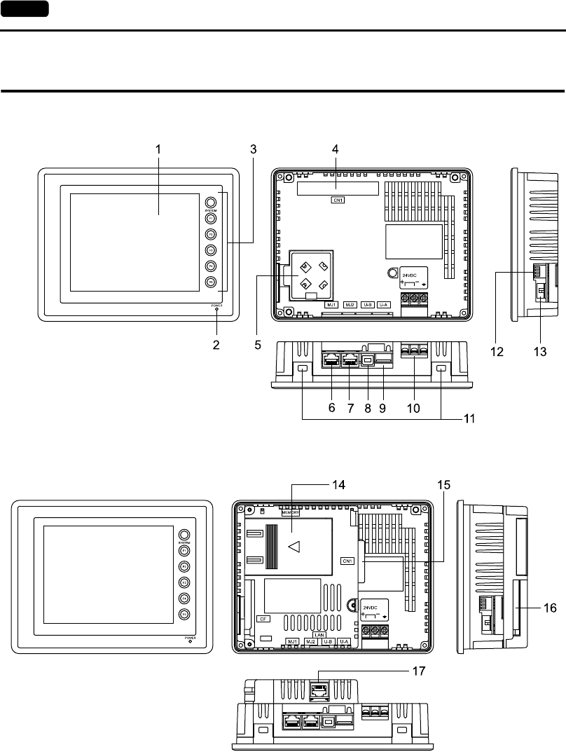
2-8 3. Names and Functions of Components
3. Names and Functions of Components
UG230
UG230+UG230A-DCL
1. Display
This is the display unit.
2. Power lamp (POWER)
Illuminates (green) when the power is supplied. The lamp illuminates (orange) when the voltage of
the battery set in the POD has become low.
3. Function switches
Used for RUN /STOP selection, contrast adjustment, brightness adjustment and backlight ON/OFF
(according to the setting). These switches can be used as user switches in the RUN mode.

2
3. Names and Functions of Components 2-9
Specifications
4. Option unit connector (CN1)
This is the connector where the option unit UG230A-DCL is mounted.
5. Battery holder
Contains a backup battery for SRAM and clock.
When the battery voltage drops, replace the battery with a new one (UG30P-BT).
6. Modular jack connector (MJ1)
This is used for screen data transfer and connection with temperature controller, barcode reader,
UG00P-MR, etc.
7. Modular jack connectors (MJ2)
This is used for connection with the PLC.
With the option unit UG230A-DCL mounted, the modular jack allows you to connect a barcode
reader, serial printer, etc.
8. USB-B (slave port)
This is the connector for screen data transfer.
9. USB-A (master port)
This is the connector where a printer or a CF card reader/writer is connected.
10. Power supply terminal block
Supplies the power (24 VDC) to the UG230.
11. Mounting holes
Used for inserting fixtures when securing the POD to the mounting panel.
12. DIP switch
This is used for setting the terminating resistors of the MJ1/MJ2 RS-422/485 signal line.
13. Slide switch
This is used for switching between the RS-232C and RS-422 ports for the MJ2.
14. Add-on memory connector (MEMORY) (optional)
With the option unit UG230A-DCL mounted, this is used for mounting an optional FLASH memory
cassette (UG230P-D4).
15. PLC communication connector (CN1) (optional)
With the option unit UG230A-DCL mounted, this is used for connecting the UG230 and a PLC or
an external control unit (computer, custom controller, etc.).
16. CF card connector (CF) (optional)
This is the connector where the CF card is inserted when the option unit UG230A-DCL is installed.
17. 10BASE-T connector (LAN) (optional)
With the option unit UG230A-DCL mounted, this is used for Ethernet connection.
2-10 4. Modular Jack (MJ1/MJ2)
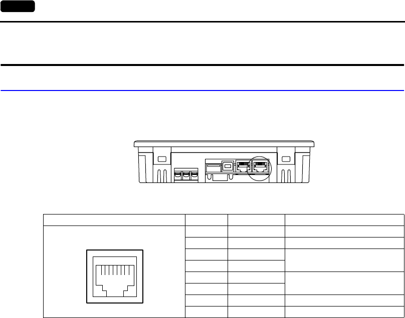
4. Modular Jack (MJ1/MJ2)
Modular Jack 1 (MJ1)
This is a modular connector used for connection for screen data transfer, temperature controller,
barcode reader, card recorder (UG00P-MR) or serial extension I/O (UG00P-U2).
The pins of modular jack 1 correspond to signals as given below.
* The maximum current for external supply (+5V) is 150 mA when the MJ1 or MJ2 is used.
Editor (UG00S-CW) Setting
1. The use of modular jack 1 can be set on the editor.
2. Select [Modular] from the [System Setting] menu. The [Modular Jack] dialog is displayed. Select
the use of modular jack 1 from the following options.
*1 Refer to “Transferring Screen Data” (page 2-17).
*2 Select this option when connecting the card recorder (UG00P-MR).
*3 Refer to “Barcode Reader Connection” (page 2-17).
*4 Select this open when “Multi-link 2” is selected for [Connection] and “1” is set for [Local Port] on the
[Comm. Parameter] dialog.
*5 Select this option when using the ladder transfer function.
*6 Select this option for Modbus slave connection.
*7 Select this option when connecting the printer with serial interface.
Refer to page 2-18.
Bottom View
MJ1 Pin No. Signal Name Contents
1 +SD/RD RS-485 +data
2−SD/RD RS-485 − data
3+5V Externally supplied +5 V
Max. 150 mA*
4+5V
5SG Signal ground
6SG
7 RD RS-232C receive data
8 SD RS-232C send data
12345678
Modular Jack 1
[Editor Port]*1
[Card Recorder]*2
[Barcode]*3
[UG00P-U2]
[Multi-Link]*4
[Temp. /PLC2Way]
[UG-Link]
[Ladder Tool]*5
[Modbus Slave]*6
[Printer (Serial Port)]*7
2
4. Modular Jack (MJ1/MJ2) 2-11
Specifications
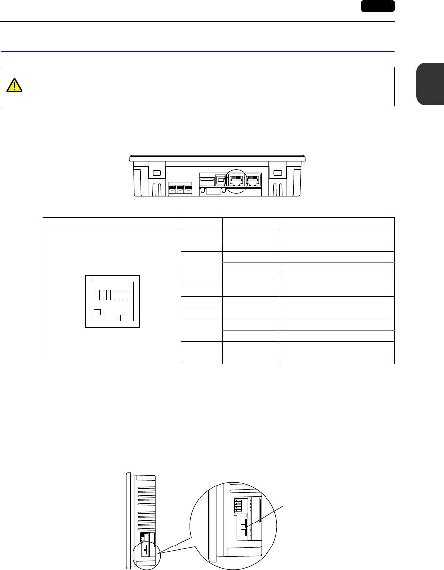
Modular Jack 2 (MJ2: Exclusive to the UG230)
This is a modular jack connector used for connection with the PLC.
Unlike the MJ1, the connector is available as an RS-422 (4-wire) port.
The pins of modular jack 2 correspond to signals as given below.
*1 Switch between RS-232C and RS-422 for pin Nos. 1, 2, 7, and 8 with the slide switch on the POD.
*2 The maximum current for the output power supply (+5 V) is 150 mA when MJ1 or MJ2 is used.
Without the Option Unit UG230A-DCL
The MJ2 is usable as a port for PLC connection.
Slide switch
•Use the switch to set the signal level for the MJ2.
Wiring
For more information, refer to page 2-14.
CAUTION
Before using the MJ2, select whether it is used as an RS-232C or RS-422 port using the
slide switch.
The switch is factory-set to RS-422.
Bottom View
MJ2 Pin No. Signal Name Contents
1Not used Not used
+SD RS-422 + send data
2Not used Not used
−SD RS-422 −send data
3+5V Externally supplied +5 V
Max. 150 mA*2
4
5SG Signal ground
6
7RD RS-232C receive data
+RD RS-422 + receive data
8SD RS-232C send data
−RD RS-422 − receive data
12345678
*1
*1
*1
*1
Side View
Slide switch
Lower position: RS-422 (4-wire)
Upper position: RS-232C
2-12 4. Modular Jack (MJ1/MJ2)
Unusable PLC models
The following PLC models cannot be connected to the MJ2.
When connecting any of the above PLCs, be sure to mount the option unit UG230A-DCL and connect
the PLC to the D-sub 25-pin connector of the unit.
Editor (UG00S-CW) Setting
When “None” is chosen for [Option Unit] on the editor, modular jack 2 is automatically used as a PLC
port.
* When “None” is chosen for [Option Unit] and “Not connect PLC” is chosen for [PLC Type], MJ2
becomes usable as when a type is chosen for [Option Unit].
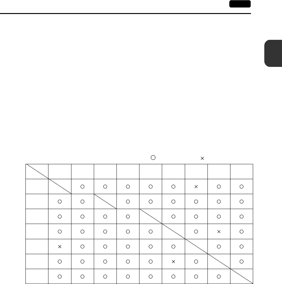
Combination of MJ1 and MJ2 functions
When “Not connect PLC” is chosen for [PLC Type], both MJ1 and MJ2 become usable as when a type
is chosen for [Option Unit]. Page 2-13 shows usable combination of functions.
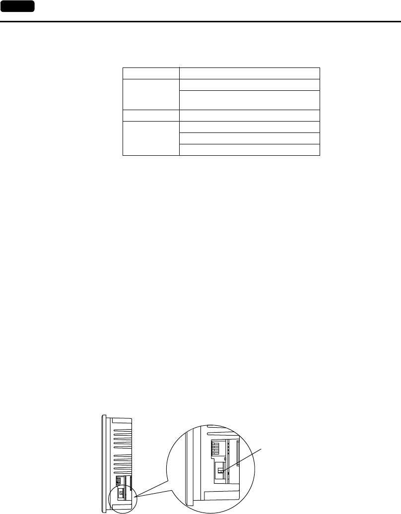
With the Option Unit UG230A-DCL
MJ2 is used to connect a temperature controller or a barcode reader. Since MJ2 is also available as
an RS-422 (4-wire) port, it differs from MJ1 in some respects.
Slide switch
•Use the switch to set the signal level for the MJ2.
•Functions used with RS-232C
Barcode reader, ladder tool (ladder transfer), printer (serial port)
•Functions used with RS-422
Multi-link 2
•Functions used with either RS-232C or RS-422 depending on the devices to be connected or
connecting methods
Temperature controller/PLC2Way, UG-Link, Modbus slave communication
Wiring
For more information, refer to page 2-16.
Manufacturer PLC
Mitsubishi
A Series CPU
FX Series CPU
(however, can be used with FX0N tool port)
Hitachi HIDIC H-series RS-232C
Siemens
S7-300MPI (HMI ADP)
S7-300MPI (PC ADP)
S7-300MPI (Helmholz SSW7 ADP)
Side View
Slide switch
Lower position: RS-422 (4-wire)
Upper position: RS-232C
2
4. Modular Jack (MJ1/MJ2) 2-13
Specifications
Editor (UG00S-CW) Setting
1. The use of modular jack 2 can be set on the editor.
2. Select [Modular] from the [System Setting] menu. The [Modular Jack] dialog is displayed. Select
the use of modular jack 2 from the following options.
Combination of MJ1 and MJ2 functions
: Usable at the same time. : Not usable at the same time
Modular Jack 2
[Not Used]
[Barcode]
[Multi-Link]
[Temp. /PLC2Way]
[UG-Link]
[Ladder Tool]
[Modbus Slave]
[Printer (Serial Port)]
MJ1
MJ2
Multi-
Link 2
Card
Recorder Barcode UG00P-U2 Temp./
PLC2Way UG-Link Ladder
Tool
Modbus
Slave
Printer
(Serial Port)
Multi-
Link 2
Barcode
Temp./
PLC2Way
UG-Link
Ladder
Tool
Modbus
Slave
Printer
(Serial Port)
2-14 4. Modular Jack (MJ1/MJ2)
Notes on Wiring
Notes on the Use of MJ1/MJ2
Notes on the Use of MJ2
Either the RS-232C or RS-422 port can be selected for MJ2 with the slide switch.
When the slide switch is set to RS-232C, MJ2 is connected in the same manner as MJ1.
When the slide switch is set to RS-422, extra care should be taken if connecting a device adapted to
RS-485 (2-wire).
PLC connection
There are two connecting methods.
One method uses an adaptor UG30C-J for connection between MJ2 and the D-sub 25-pin connector
plus a PLC communication cable (as shown in the User’s Manual <PLC Connection> (FEH380)).
The other method uses a UG00C-P cable for connection between MJ2 and a PLC interface cable.
For information on the PLC wiring diagram, refer to the separate User’s Manual <PLC Connection>
(FEH380).
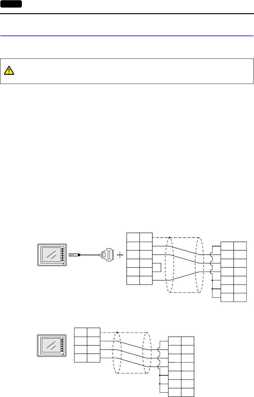
•Connecting to an RS-232C port (example: Mitsubishi A1SJ71UC24-R2):
CAUTION
The metal shell of the UG230 modular jack is used as SG (signal ground).
Fuji’s communication cable for modular jack, shielded cable, is connected to the SG
inside the UG230.
With UG30C-J
With UG00C-P
PLC
1
2
3
4
5
7
RD
SD
RS
CS
DR
SG
CD 1
2
3
5
6
7
8
FG
SD
RD
RS
CS
SG
MJ2
UG30C-J
D-sub 25-pin (Male)
D-sub 9-pin (Male)
POD PLC communication cable
PLC
RD
SD
RS
CS
DR
SG
CD 1
2
3
5
6
7
8
SG
SD
RD
SG
MJ2
SHELL
8
7
5
RJ-45 8-pin UG00C-P
D-sub 9-pin (Male)
2
4. Modular Jack (MJ1/MJ2) 2-15
Specifications
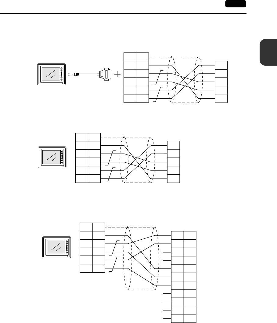
•Connecting to an RS-422 port (example: Mitsubishi QJ71C24):
* When connecting to a Mitsubishi QnA CPU port, a connection between MJ2 and the PLC can
be established by changing the PLC-side connecting method.
MJ2
UG30C-J
PLC
SDA
SDB
SG
RDB
RDA
1
7
12
13
24
25
SG
+SD
-SD
+RD
-RD
FG
D-sub 25-pin (Male)
POD PLC communication cable
PLC
SDA
SDB
SG
RDB
RDA
SG
+SD
-SD
+RD
-RD
MJ2
5
1
2
7
8
SHELL
SG
RJ-45 8-pin UG00C-P
With UG30C-J
With UG00C-P
MJ2
PLC
SG
SG
+SD
-SD
SHELL
5
1
2
2
7
15
+RxD
SG
-RxD
16 -TxD
4 +DSR
17 -DSR
5 +DTR
18
20
-DTR
21
3 +TxD
+RD
-RD
7
8
D-sub 25-pin (Male)
RJ-45 8-pin UG00C-P Mitsubishi QnA CPU
2-16 4. Modular Jack (MJ1/MJ2)
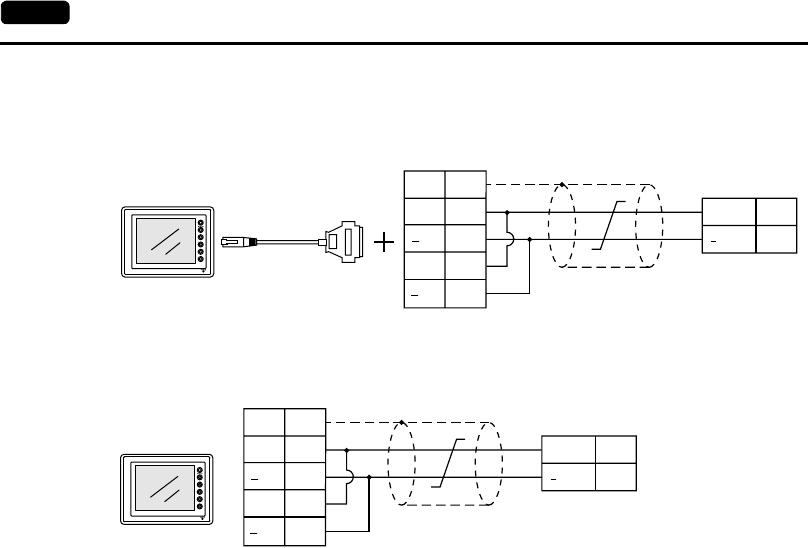
•Connecting to an RS-485 port (example: Siemens S7-300 MPI port):
Temperature controller/PLC2Way/UG-Link/Modbus slave communication
For information on the wiring diagram, contact your local distributor.
MJ2
UG30C-J
FG
+SD
SD
+RD
PLC
+RD/SD
RD/SD
3
8
RD
1
12
13
24
25
D-sub 25-pin (Male)
POD PLC communication cable
SG
+SD
SD
+RD
PLC
+RD/SD
RD/SD
3
8
RD
SHELL
1
2
7
8
MJ2
RJ-45 8-pin UG00C-P
With UG30C-J
With UG00C-P
2
4. Modular Jack (MJ1/MJ2) 2-17
Specifications
Transferring Screen Data
•Use modular jack 1 (MJ1) when transferring screen data.
•When [Editor Port] is selected for [Modular Jack 1] on the editor, it is possible to transfer data in the
RUN mode because the RUN/STOP mode (on the Main Menu screen) can be automatically
selected.
Also RUN/STOP mode is automatically selected for on-line editing and simulation.
•When an option other than [Editor Port] is selected for [Modular Jack 1], select the STOP mode
(on the Main Menu screen) and transfer screen data. Simulation or on-line editing is not available.
•When transferring screen data, use Fuji’s data transfer cable (UG00C-T) 3 m to connect the
UG230 to a personal computer.
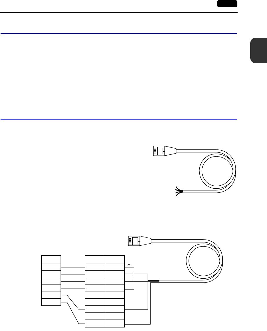
Barcode Reader Connection
•It is possible to receive the signal from a barcode reader by connecting the barcode reader at the
modular jack (MJ1/2) of the UG230.
•To connect a barcode reader to the modular jack
(MJ1/2), use Fuji’s optional cable (UG00C-B).
Length: 3 m
with modular plug
•Notes on connection
- In the case of barcode readers with CTS and
RTS control, it may be necessary to install a
jumper to RTS and CTS. Otherwise the
barcode reader may not work correctly.
- The external power supply (+5 V) is max. 150
mA.
(Refer to page 2-10.)
•When using the barcode reader that was connected to UG400 (POD’s old version), connect it to
the D-sub 9-pin female connector using the UG00C-B cable as shown below.
12345678
Brown: +5V
Red: 0V
Orange: RD
Yellow: TD
Pin No
1
2
3
4
5
6
7
8
9
CS
RD
SD
RS
SG
+5V
12345678
RTS
TXD
RXD
CTS
SG
+5V
Signal
Orange: RD
Signal
Name
* Install a jumper between
CTS and RTS.
Yellow : SD
Red: 0 V
Brown: +5 V
D-sub 9-pin (female)Barcode reader
2-18 4. Modular Jack (MJ1/MJ2)
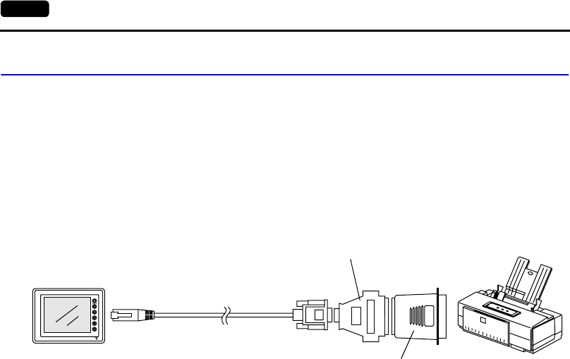
Printer Connection (Serial Printer)
•To connect a printer through serial interface, connect the cable to a modular jack (MJ1/MJ2).
•Refer to the specification sheet of the printer to be used for the connecting cable for serial
interface. For information on MJ1/MJ2 signals, refer to page 2-10.
•To connect to a printer equipped with a parallel interface, use a commercially available
parallel-serial converter.
When the serial connector of the converter is a D-sub 9-pin male connector, use Fuji’s UG00C-T
connection cable.
Compatible Printer Models
Control code system:
•PR201 PC-PR201 series compatible with MS-DOS computer
•ESC-P ESC/P24-J84, ESC/P-J84, ESC/P super function compatible
with MS-DOS computer
Others
•CBM292/293 CBM’s line thermal printer
(Screen hard copying is not possible.)
•MR400 Sato’s barcode printer “MR400 series”
(It is not possible to print a screen hard copy, data sheet or
sampling data.)
•EPSON STYLUS PHOTO series EPSON color ink jet printer STYLUS PHOTO series
(For printer models, refer to the User’s Manual
<Supplementary Manual> (FEH376-1).)
Screen Data Setting
From the [System Setting] menu, select [Printer Setting] and open the [Main] tab window.
•Type: (as desired)
•Port: Serial Port (MJ Port) → Go to the [Serial Port] tab window for communication setting.
↓
[Refer to Modular] button
↓
•Modular Jack 1 (or 2)
Printer (Serial Port)
Set the above options.
MJ
UG230
Printer
UG00C-T
Parallel ←→ serial converter
D-sub 25-pin ←→ 9-pin converter
Parallel port
2
5. USB Connectors 2-19
Specifications
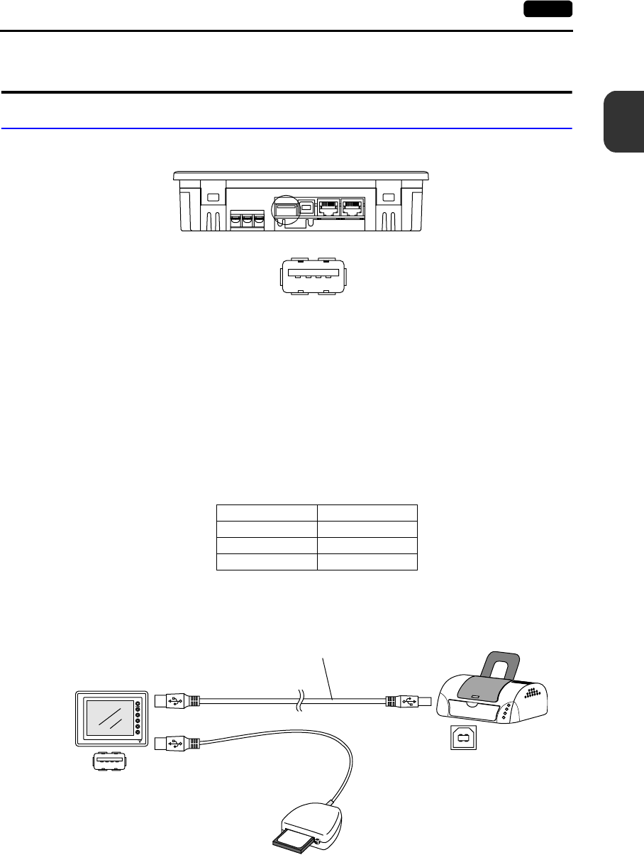
5. USB Connectors
USB-A (Master Port)
Available Devices
Printer
•EPSON color ink jet printer STYLUS PHOTO for USB port
* For more information, refer to User’s Manual <Supplementary Manual> (FEH376-1).
•Printer with parallel interface
Printer models and available print functions are the same as those for a serial printer (page 2-18).
CF card reader/writer
Recommended models are:
Connecting Cable
•Use the cable included with the device to be connected (printer or CF card reader/writer).
Bottom View
Enlarged View
Manufacturer Type
I-O Data Device USB-CFRW
TDK U2RW03CF
ELECOM MR-UCF1SV
USB-A
USB-B
C F R W
96
MB
UG230
Printer
USB cable
CF card reader/writer
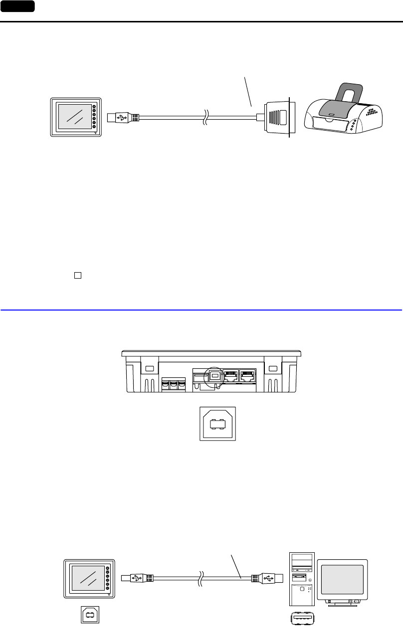
2-20 5. USB Connectors
•To connect to a printer equipped with a parallel interface, use a commercially available parallel
←→ USB cable (ELECOM UC-PGT recommended).
Screen Data Setting
For a printer
From the [System Setting] menu, select [Printer Setting] and open the [Main] tab window.
•Type: (as desired)
•Port: USB Port
For CF card reader/writer
From the [System Setting] menu, select [Unit Setting], and open the [Option Unit] tab window.
•[ Use USB CF Card Reader]: checked
USB-B (Slave Port)
This is a connector for screen data transfer via USB.
* When transferring screen data via the USB-B (USB slave port), be sure to install the USB driver for
POD on the computer. The steps are described in the following section “Installing the USB Slave
Driver.”
Screen data transfer via the USB port is available with Windows 98 Second Edition and later.
Connecting cable
Use a commercially available USB cable.
USB-A
UG230
Printer
Parallel ←→ USB cable
Parallel port
Bottom View
Enlarged View
USB-AUSB-B
RESET
disc
UG230 Computer
USB cable
2
5. USB Connectors 2-21
Specifications
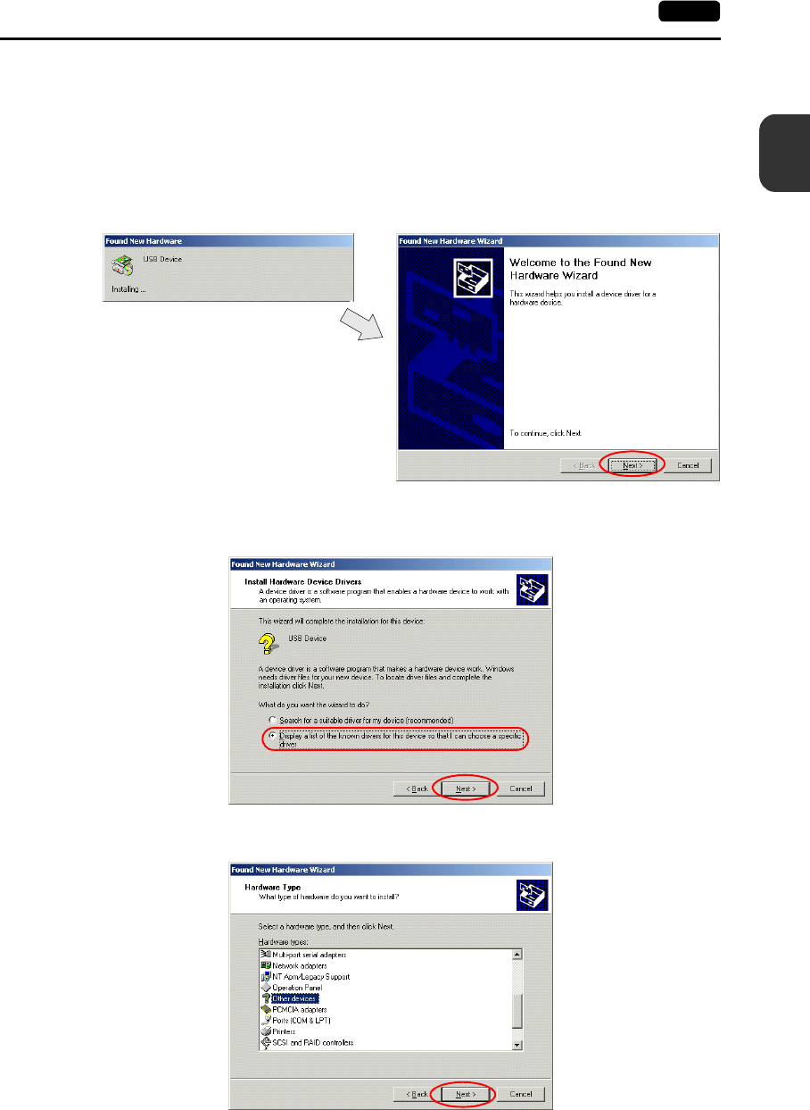
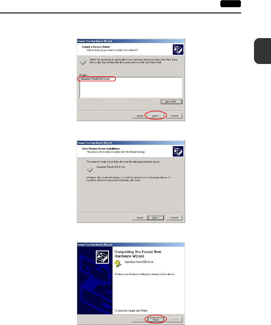
Installing the USB Slave Driver
The installation procedure on Windows 2000 is described as an example below.
1. Connect the USB-B port of the UG230 (with power on) to the computer (with power on) using a
USB cable.
2. The message “Found New Hardware” and then the driver installation wizard appear on the
computer. Click the [Next] button.
3. When the dialog box below is displayed, select [Display a list of the known drivers for this device
so that I can choose a specific driver] and click the [Next] button.
4. The dialog box below is displayed. Select [Other Devices] and click the [Next] button.
2-22 5. USB Connectors
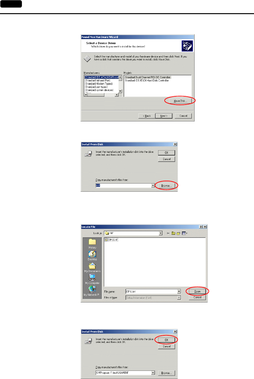
5. The dialog box below is displayed. Click [Have Disk].
6. The [Install From Disk] dialog box is displayed. Click the [Browse] button.
7. The UG230 USB driver “OP-U.inf” is automatically stored in the “inf” folder within the UG00S-CW
editor installation folder (“UGW” for example).
Select the “OP-U.inf” file and click the [Open] button.
8. The previous dialog box is displayed again. Check the path shown under [Copy Manufacturer’s
Files From:] and click the [OK] button.
2-24 5. USB Connectors
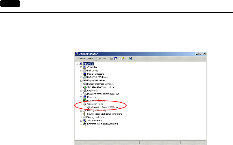
Recognition of USB Driver
When the driver has been installed successfully and the UG230 and the computer are connected with
a USB cable, the [Device Manager] window shows “Operation Panel - Operation Panel USB Driver.”
This will disappear when the UG230 and the computer are disconnected.
If [Other Device] or [?] is shown even while their connection via USB is maintained, the USB driver
may not be recognized. If this happens, uninstall the USB driver once and reinstall it.
2
6. D-sub 25-Pin Connector (CN1) (Optional) 2-25
Specifications
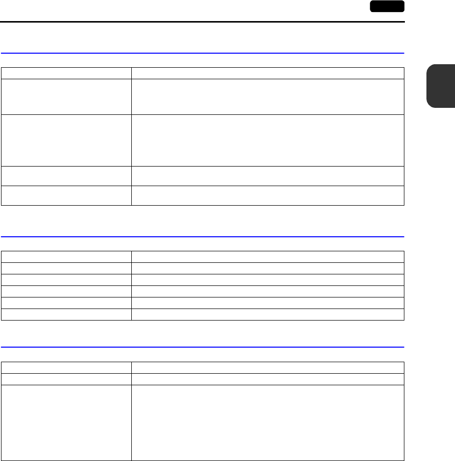
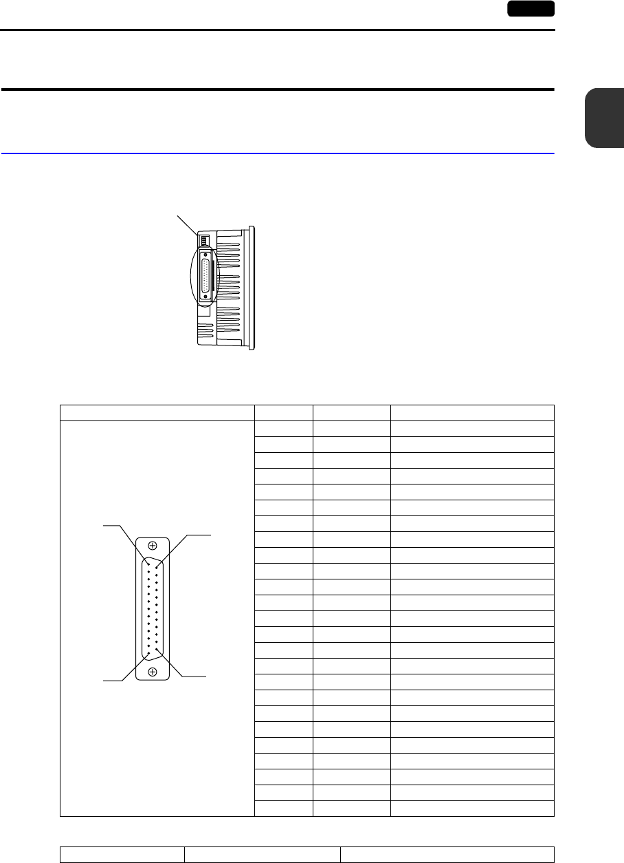
6. D-sub 25-Pin Connector (CN1) (Optional)
When the option unit UG230A-DCL is mounted, the CN1 connector is usable.
Serial Connector (CN1)
To communicate with the PLC (RS-232C, RS-422/485), connect the cable to the serial connector
(CN1).
The correspondence between the serial connector pins and signals is shown below. The interface is
the same as that for the UG30-series CN1.
The following connector is recommended.
CN1 (D-sub 25-pin, female) Pin No. Signal Name Contents
1 FG Frame ground
2 SD RS-232C send data
3 RD RS-232C receive data
4 RS RS-232C RS request to send
5 CS RS-232C CS clear to send
6 Not used
7 SG Signal ground
8 Not used
9 +5V Use prohibited
10 0V Use prohibited
11 Not used
12 +SD RS-422 send data (+)
13 −SD RS-422 send data (−)
14 +RS RS-422 RS send data (+)
15 Not used
16 Not used
17 −RS RS-422 RS send data (−)
18 −CS RS-422 CS receive data (−)
19 +CS RS-422 CS receive data (+)
20 Not used
21 −Use prohibited
22 −Use prohibited
23 Not used
24 +RD RS-422 receive data (+)
25 −RD RS-422 receive data (−)
Recommended connector DDK-make 17JE23250-02 (D8A) D-sub 25-pin, male, metric thread, with hood
UG230A-DCL
114
13
25
2-26 7. 10BASE-T (LAN) (Optional)
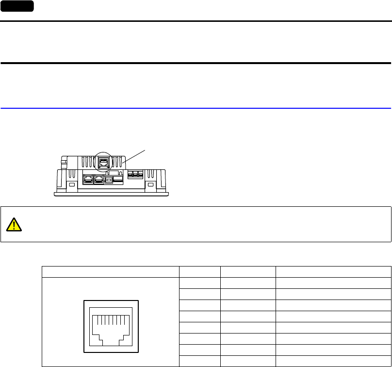
7. 10BASE-T (LAN) (Optional)
When the option unit UG230A-DCL is mounted, the 10BASE-T (LAN) connector is usable.
10BASE-T Connector
Use this connector for Ethernet connection.
The LAN (10BASE-T) pins correspond to signals as given below.
Bottom View UG230A-DCL
CAUTION
MJ1/2 and LAN connector are 8-pin modular jacks.
Check the name plate and insert the connector in the correct position.
LAN Pin No. Signal Name Contents
1 TX+ Ethernet send signal (+)
2TX−Ethernet send signal (−)
3 RX+ Ethernet receive signal (+)
4 NC Not used
5 NC Not used
6RX−Ethernet receive signal (−)
7 NC Not used
8 NC Not used
12345678
2
7. 10BASE-T (LAN) (Optional) 2-27
Specifications
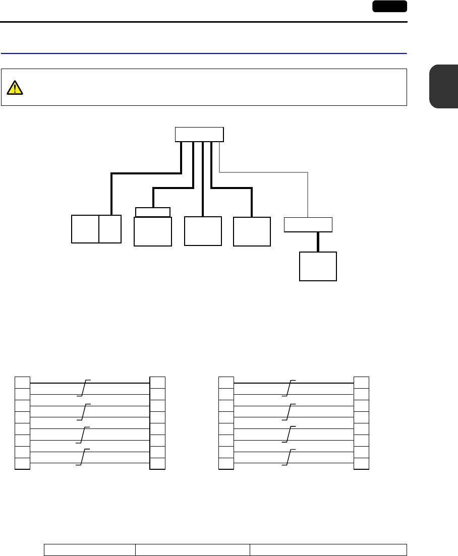
Notes on Wiring
Cable Connection Diagram
Notes on Cables
Use the following recommended cable.
CAUTION
When using the LAN port, keep the LAN cable away from the power supply cable as
much as possible.
UG230A-DCL
UG230
PLC
HUB
HUB
UTP cable
Straight or cross cable
(For more information, refer
the HUB specifications.)
Node
Node
Distance between the node and the HUB: 100 m maximum
Maximum network nodes: 100
UTP cable
Straight
Ethernet
Unit
UG30
high-
performance
type
Straight
(with HUB)
Cross
(without HUB)
10BASE-T
RJ-45 8Pin
1
2
3
6
4
5
7
8
1
2
3
6
4
5
7
8
10BASE-T
RJ-45 8Pin
1
2
3
6
4
5
7
8
3
6
1
2
5
4
8
7
10BASE-T
RJ-45 8Pin
10BASE-T
RJ-45 8Pin
* Unshielded twist-pair cable * Unshielded twist-pair cable
Recommended cable 10BASE-T Type: Twist-pair cable, category 5
2-28 8. CF Card
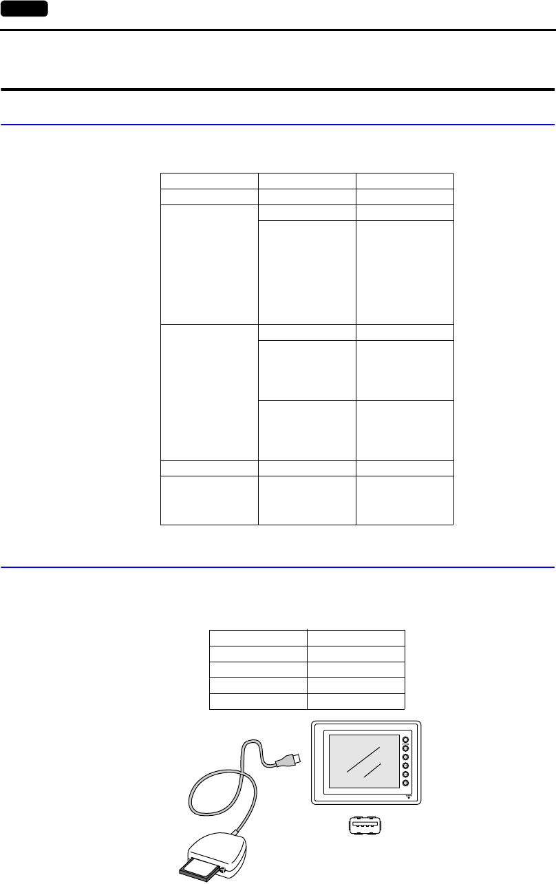
8. CF Card
Recommended CF Cards
CF cards in compliance with CompactFlashTM can be used.
The operation of the following cards has been verified by us.
CF Card Insertion Position
With the USB port:
The following items are recommended.
Manufacturer Type Capacity
Kodak KPCN-32 32 MB
SanDisk
SDCFB-64-505 64 MB
SDCFB-xxxx-801
32 MB
64 MB
96 MB
128 MB
192 MB
256 MB
384 MB
512 MB
1 GB
I-O Data Device
CFS-32MA 32 MB
CFS-xxM(HI)
32 MB
64 MB
128 MB
256 MB
512 MB
CFS-iVxxx
32 MB
64 MB
128 MB
256 MB
512 MB
Hagiwara Sys-Com HPC-CFxxZX 32 MB
Melco RCF-XX
64 MB
128 MB
256 MB
512 MB
Manufacturer Type
I-O Data Device USB-CFRW
TDK U2RW03CF
ELECOM MR-UCF1SV
DAZZLE DM-8000
C F R W
96
MB
USB-A
2
8. CF Card 2-29
Specifications
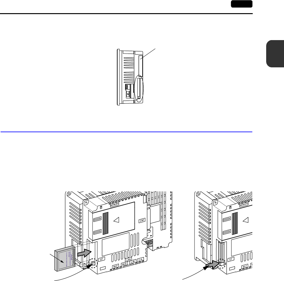
With the option unit:
Insert a CF card into the CF connector of the option unit UG230A-DCL.
Mounting and Dismounting the CF Card
With the USB port:
Follow the instructions provided in the CF card reader/writer manual.
With the option unit:
1. Insert the card securely into the interface with the card backside outwards viewed from the rear of
the unit as shown below.
2. To remove the card, press the eject button. The card pops out.
UG230A-DCL
Card backside
When the card is inserted,
the eject button pops out. 2.

2-30 8. CF Card
Notes on Handling the CF Card
1. POD can recognize a CF card in the FAT file system. It cannot recognize a FAT32-formatted CF
card.
2. Do not insert or remove the CF card during access. Doing so may destroy data on the CF card.
The CF card can be inserted or removed safely when the Main Menu screen is displayed. Before
mounting or removing the CF card, be sure to check that the CF card is not being accessed.
Doing so may destroy data on the CF card or cause CF card failure.
However, if the [Card Menu] switch is pressed on the Main Menu screen and the CF card
operation screen is displayed, it is not possible to insert or remove the CF card.
3. Do not turn the power off or on during access to the CF card.
4. Make a backup copy of the CF card at regular intervals.
5. If there should be a disk error and you cannot read/write data, you can scan the disk in Windows to
restore the disk data.
If not restored, initialize the CF card. Note that the data in the CF card will be completely deleted
by initialization. (For more information on scanning the disk or operating Windows, refer to the
Windows manual.)
6. The number of writing times per CF card is limited (approx. 300,000 times).
Consequently, frequent writing at short intervals may shorten service life of the CF card. When
using a CF card to save sampling data, be aware of the sampling time. Be sure to always avoid
writing to a CF card with the CYCLE macro command.

3
1. Mounting Procedure 3-1
Installation
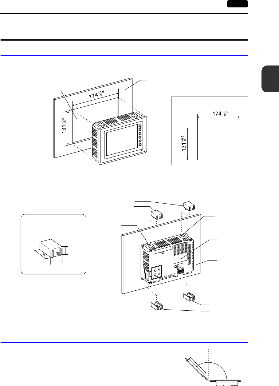
1. Mounting Procedure
Mounting Procedure
1. Insert the UG230 into the mounting panel (max. thick: 5 mm).
2. Insert four fixtures attached to the UG230 into the mounting holes, and tighten them with the
locking screws.
Tightening Torque: 0.3 to 0.5 N•m
3. Mount the gasket so that it will be sandwiched securely between the unit and the mounting panel.
Mounting Angle
Install the unit within the angle of 0° to 135° as shown on the right.
Mounting panel
Panel cut-out hole
• Panel cut-out dimensions
(Unit: mm)
17.8
10.5
30.0
Fixture dimensions
(Unit: mm)
Fixtures
Mounting hole
Mounting hole
UG230
Mounting
panel
Fixtures
* To prevent static electricity, be sure to
connect the mounting panel to the ground.
0°
135°
90°
Display
Display
3-2 2. Power Supply Cable Connection
2. Power Supply Cable Connection
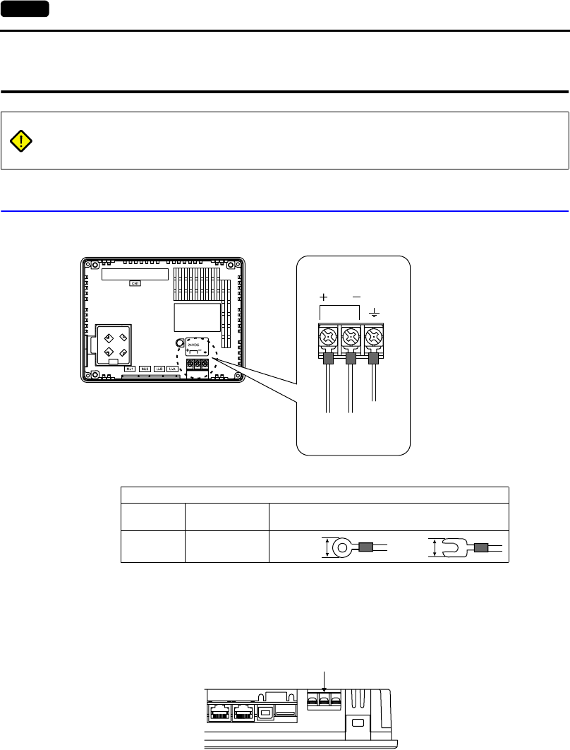
Power Supply Cable Connection
•Connect the power supply cable to the terminal on the backside of the unit.
•Tighten terminal screws on the power supply terminal block with the following torque.
•The power source must be within the allowable voltage fluctuation.
•Use a power source with low noise between the cables or between the ground and the cable.
•Use as thick a power supply cable as possible to minimize drop in voltage.
•Keep power supply cables away from high-voltage, large-current carrying cables.
•Be sure to attach the terminal cover to the terminal block.
DANGER Electric shock hazard
Shut the power off before connecting the power supply cable.
24 VDC
Power supply
24 VDC ± 10%
Grounding
24 VDC
Terminal Screw
Screw Size Tightening
Torque Crimp-style Terminal (Unit: mm)
M3.5 0.5 N•m 7.1 MAX 7.1 MAX
Terminal cover
3
2. Power Supply Cable Connection 3-3
Installation
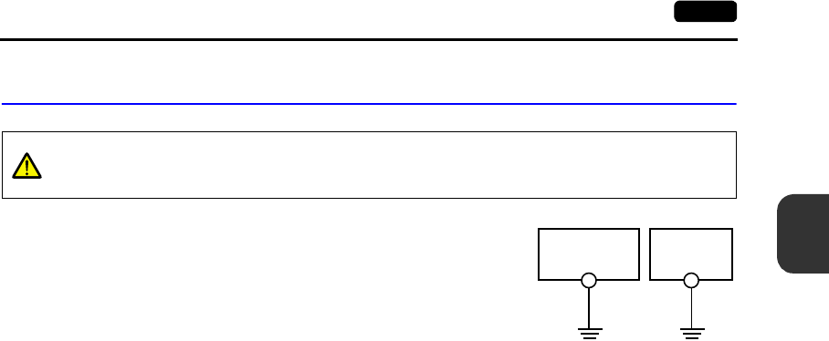
Grounding
•An independent earth pole must be used for POD.
•Use a cable which has a nominal cross section of more than
2mm
2 for grounding.
•Set the grounding point near the POD to shorten the distance
of grounding cables.
CAUTION
Be sure to establish a ground of POD.
(The level of grounding resistance should be less than 100 Ω.)
POD Other
equipment
3-4 2. Power Supply Cable Connection
Please use this page freely.

4
1. Coin-type Lithium Battery 4-1
Instructions
1. Coin-type Lithium Battery
Battery Mounting Procedure
1. Turn the unit off.
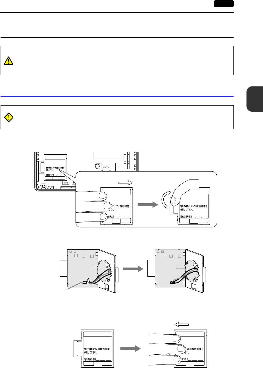
2. Slide the battery holder cover in the direction of the arrow (“→” shown below) to open it.
3. Check that the battery is securely attached to the backside of the cover, and connect the battery
connector.
4. Close the battery holder cover. When closing the cover, slide it in the direction of the arrow (“←“
shown below) to lock it.
CAUTION
The POD is delivered without inserting the battery connector in the battery holder on the
back of the unit.
Be sure to set the battery when using the calendar function or SRAM.
Without battery, the contents in the SRAM or calendar will not be retained.
DANGER Electric shock hazard
Steps 2 to 5 must be performed when the power to the POD is turned off.
See operating or maintenance
instruction for type of battery
to be used.
Battery replacement.
See operating or maintenance
instruction for type of battery
to be used.
Battery replacement.
See operating or maintenance
instruction for type of battery
to be used.
Battery replacement.
Slide and open.
Battery connector
See operating or maintenance
instruction for type of battery
to be used.
Battery replacement.
See operating or maintenance
instruction for type of battery
to be used.
Battery replacement.
Slide and lock.
4-2 1. Coin-type Lithium Battery
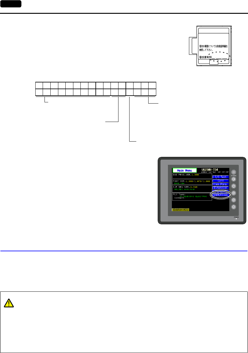
5. Enter a date five years from now for “Battery Replacement”
on the sticker on the battery holder.
* The battery status is output to the internal memory
$s167 of the UG230.
If the battery voltage drops before five years has
elapsed, replace the battery immediately.
6. Turn on the power to the UG230 and check that the
battery is correctly mounted on the Main Menu
screen.
When the battery is not connected, the [SRAM/Clock]
switch blinks and the message “Battery not set” is
displayed at the bottom left corner. When the battery
is correctly connected, the [SRAM/Clock] switch goes
out and the message is cleared.
When the battery voltage has dropped, the message
“Brownout Battery” is displayed.
Battery Replacement
Safety Instructions on Handling the Battery
Lithium batteries contain combustible material such as lithium or organic solvent. Mishandling may
cause heat, explosion or ignition resulting in fire or injury. To prevent accidents, pay attention to the
following cautions when handling the lithium battery.
See operating or maintenance
instruction for type of battery
to be used.
Battery replacement.
Enter a date five years from now
$s167
15 14 13 12 11 10 09 08 07 06 05 04 03 02 01 00
0000000000 0
MSB LSB
Memory cassette information
reserved (Setting: 0) 0: Not mounted
1: FROM 2 Mbyte (UG20)
2: FROM 4 Mbyte (UG230/UG20)
3: SRAM 512 kbyte (UG30/UG20)
4: FROM 8 Mbyte (UG30)
0: The battery is normal.
1: Battery voltage drop
2: Battery not mounted
Memory cassette information reserved (Setting: 0)
Main Menu screen
CAUTION
•Be sure to discharge static electricity from your body before battery replacement.
•Use the battery “UG30P-BT” (replacement battery for the UG30) for replacement.
•Rough handling of the battery may cause a fire or chemical burn hazard.
•Do not disassemble, incinerate or heat the battery.
•Observe the local and governmental regulations when disposing of waste batteries.
•Keep batteries out of reach of children (If swallowed, immediately consult a doctor.)
•Never re-charge the battery.
•When the battery leaks or smells, the leaking battery electrolyte may catch a fire.
Keep from heat or flame.
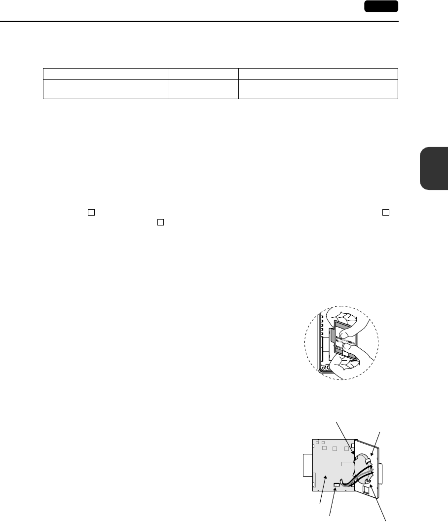
4
1. Coin-type Lithium Battery 4-3
Instructions
Battery Replacement Procedure
Replacement batteries are available from us.
1. Replace the battery “UG30P-BT” within three minutes after the unit is turned off.
If it is not possible to replace within three minutes, use the UG00S-CW editor (cable: UG00C-T) or
a CF card and make a backup copy of data in the SRAM.
•When using the UG00S-CW editor:
1) Start the UG00S-CW editor.
2) Click the [Transfer] icon. The [Transfer] dialog is displayed.
3) Select [Display] for [Transfer Device] and [SRAM Data] for [Transfer Data].
To save a backup copy from the UG00S-CW editor on the server via Ethernet, check
[ Transfer through Ethernet/IP Address of the UG30 Equipped with SRAM]. Keep [
Use Simulator] and [ Read Comments in Data Transfer] unchecked.
4) Click the [PC <-] under [Transfer Mode].
5) Save the read data in the “∗.RAM” file.
•When using a CF card:
For the backup procedure with a CF card, refer to “Chapter 6 POD Operations.”
2. Turn the unit off. Slide and open the battery holder. The battery in the socket will come into view.
3. Unplug the battery connector, and remove the battery from the
socket. Take out the battery while pressing the center of the
battery holder cover as shown in the figure.
4. Set a new battery. Fit the battery into the socket in such a
manner that the red cable side of the battery faces the board
and the cable faces out. Insert the battery in the “a” side first,
and push it down to “a” while inserted in the “b” side.
5. Plug in the battery connector and slide and lock the battery
holder cover.
6. Remove the existing caution sticker. Enter a date five years
from now for “Battery Replacement” on the new caution sticker,
and attach it to the backside of the unit.
7. When the backup copy of the SRAM data has been saved in
step 1, turn on the unit and load the data to the unit.
Name Type Contents
Replacement battery for the UG30 UG30P-BT • Coin-type lithium primary cell 1 pce
• Cautions sticker 1 pce
See operating or maintenance
instruction for type of battery
to be used.
Battery replacement.
“a” side
Battery holder
Battery
connector
Printed circuit
board
“b” side
Socket
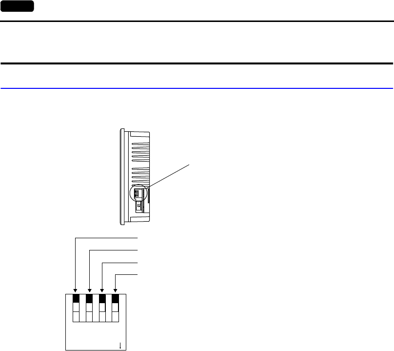
4-4 2. DIP Switch Setting
2. DIP Switch Setting
DIP Switch (DIPSW) Setting
When setting the DIP switch, turn the power off.
Terminating Resistance Setting (DIPSW1, 2, 3)
Set the terminating resistance for RS-422/485 connection.
•MJ1 can be used for RS-232C or RS-485 (2-wire) connection.
For the following connections, set DIPSW 1 to the ON position.
- Master station for multi-link 2 connection
- Temperature controller network/PLC2Way connection via RS-485
- Card Recorder: Connection with the UG00P-MR (optional)
- Serial extension I/O: Connection with the UG00P-U2 (optional)
- Connection to the UG230 at the termination of UG-link connection via RS-485
•MJ2 can be used for RS-232C or RS-422 (4-wire) connection.
- For connection to the PLC through the RS-422 interface (4-wire connection) at MJ2, set
DIPSW2 and 3 to the ON position.
- For connection to the PLC through the RS-422 interface (2-wire connection) at MJ2, set
DIPSW3 to the ON position.
CF Auto Load (DIPSW4)
A screen data file saved on a CF card can be auto-loaded as described below.
1. Transfer screen data from the computer to a CF card. (Refer to the User's Manual <Function>
(FEH376) for more information.)
2. Set DIPSW4 in the ON position, and insert the CF card that contains the screen data file.
3. Turn the unit on. The screen data is automatically loaded into the FLASH memory of the unit.
Side View
DIP switch
1234
ON
CF auto load (for USB/UG230A-DCL)
MJ2 (modular jack 2) SD terminating resistance for RS-422
MJ1 (modular jack 1) terminating resistance for RS-485
MJ2 (modular jack 2) RD terminating resistance for RS-422
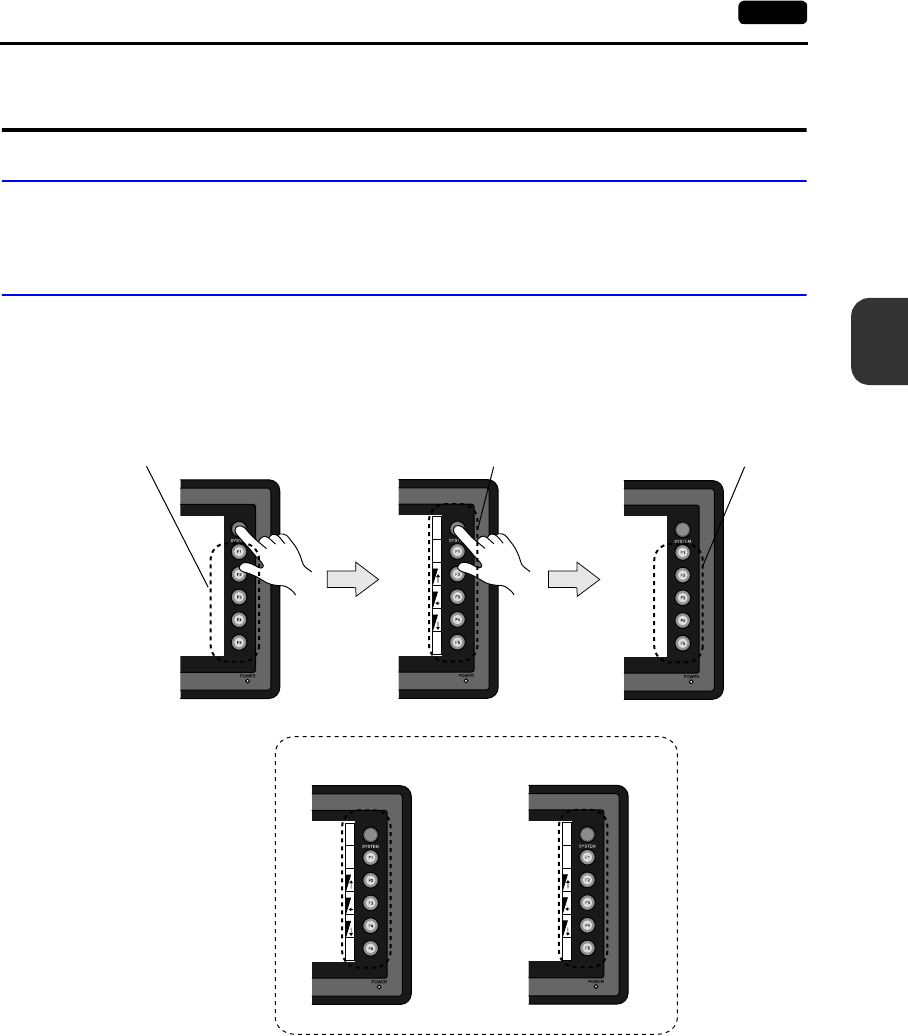
4
3. Function Switches 4-5
Instructions
3. Function Switches
Types
•There are six function switches provided.
[SYSTEM], [F1], [F2], [F3], [F4], [F5]
[SYSTEM] Switch
The [SYSTEM] switch works in “alternate” operations.
When this switch is pressed once, the switch menu is displayed at the side of the function switches
[F1] to [F5], and each function switch corresponds to the menu item displayed in the switch menu.
When the [SYSTEM] switch is pressed again, the switch menu disappears, and the function switches
[F1] to [F5] work as defined by the user (page 4-6).
BR
BR
BR
S
Y
S
M
O
D
E
B
K
L
T
BR
BR
BR
S
Y
S
M
O
D
E
B
K
L
T
CT
CT
CT
S
Y
S
M
O
D
E
B
K
L
T
Function switches for switch
menu selection
User-defined function
switches
User-defined
function switches
For UG230H-TS4: For UG230H-SS/LS:
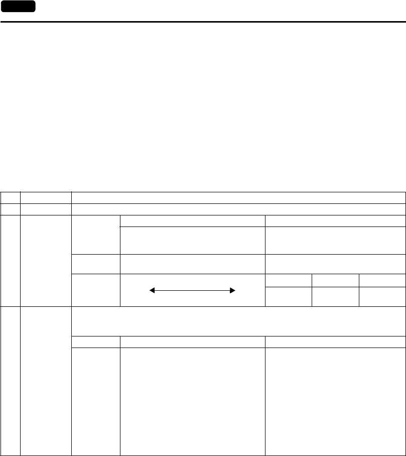
4-6 3. Function Switches
User-defined Function Switches [F1] to [F5]
•When the UG230 is in the STOP mode, the function switches do not work.
•When the UG230 is in the RUN mode and the switch menu by the [SYSTEM] switch is not
displayed, the function switches can be defined by the user.
•User-defined function switches should be set in the following dialogs of the UG00S-CW editor.
- Settings for each screen
[Edit] → [Local Function Switch Setting] → [Function Switch Setting] dialog
- Setting for all screens
[System Setting] → [Function Switch Setting] → [Function Switch Setting] dialog
[F1] to [F5] Switch Functions with Switch Menu
*1 When a medium or dark brightness is set, the backlight service life may become shorter.
Functions Contents
F1 Mode Selects the operation mode between STOP ↔ RUN.
F2
F3
F4
Contrast
Brightness
Item
Contrast Adjustment Brightness Adjustment
Adjust the contrast. Holding down the
switch for one second or more changes the
contrast rapidly.
Adjusts the screen brightness in three
levels.
Applicable
models UG230H-SS/LS UG230H-TS
Adjustment
F2 F3 F4
Dark Medium Pale
F2 F3*1 F4*1
1
Bright
2
Medium
3
Dark
F5 Backlight
Turn the backlight on and off.
Backlight control should be set on the UG00S-CW editor.
([System Setting] → [Unit Setting] → [Unit Setting] dialog, [Backlight] tab window)
Always ON Auto 1/Auto 2/Auto 3 Manual/Manual 2
Ignored • The [F5] switch turns the backlight off.
• This is valid when the backlight control
bit (bit 11) in the read area “n + 1” in the
system memory is reset (OFF: 0).
• Manual
The [F5] switch turns the backlight off.
To turn it on, press somewhere on the
screen or a function switch.
• Manual 2
The [F5] switch turns the backlight on
and off.
• [Backlight Power ON Time Control] that
determines the backlight status at
power-up becomes valid.
When the power is turned on:
ON → Backlight ON
OFF → Backlight OFF

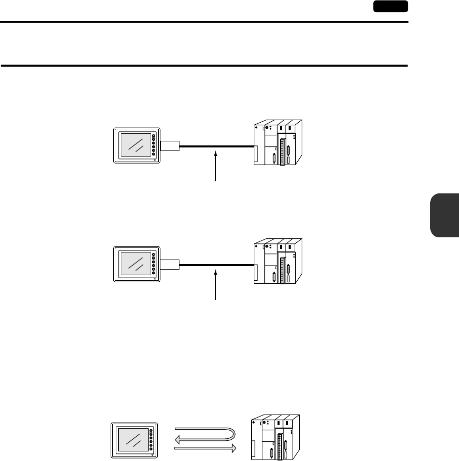
5
1. 1 : 1 Connection 5-1
Connections
1. 1 : 1 Connection
•One set of the UG230 is connected to one PLC (1 : 1 connection).
•The host link unit of the PLC or the CPU port is used and the UG230 (master station) establishes
communications according to the protocol of the PLC. Consequently, it is not necessary to have
the dedicated communication program on the PLC (slave station). The UG230 reads the PLC
memory for screen display. It is also possible to write switch data or numerical data entered
through the keypad directly to the PLC memory.
•For more information on wiring and communication settings, refer to the User’s Manual <PLC
Connection> (FEH380).
. . .
. . .
. . .
. . .
. . .
. . .
. . .
. . .
. . .
. . .
. . .
. . .
. . .
. . .
. . .
. . .
RUN
STOP
PLC
MJ2
. . .
. . .
. . .
. . .
. . .
. . .
. . .
. . .
. . .
. . .
. . .
. . .
. . .
. . .
. . .
. . .
RUN
STOP
PLC
CN1
RS-232C or RS-422 (RS-485)
UG230
RS-232C or RS-422 (RS-485)
UG230
[UG230 only]
[UG230 + UG230A-DCL]
. . .
. . .
. . .
. . .
. . .
. . .
. . .
. . .
. . .
. . .
. . .
. . .
. . .
. . .
. . .
. . .
RUN
STOP
PLC
Read
Write
UG230
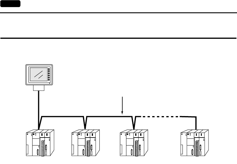
5-2 2. 1 : n Connection (Multi-drop)
2. 1 : n Connection (Multi-drop)
One UG230 is connected to multiple PLCs. (Maximum connectable PLCs: 32)
•For more information on wiring and communication settings, refer to the User’s Manual <PLC
Connection> (FEH380).
. . .
. . .
. . .
. . .
. . .
. . .
. . .
. . .
. . .
. . .
. . .
. . .
. . .
. . .
. . .
. . .
RUN
STOP
. . .
. . .
. . .
. . .
. . .
. . .
. . .
. . .
. . .
. . .
. . .
. . .
. . .
. . .
. . .
. . .
RUN
STOP
. . .
. . .
. . .
. . .
. . .
. . .
. . .
. . .
. . .
. . .
. . .
. . .
. . .
. . .
. . .
. . .
RUN
STOP
. . .
. . .
. . .
. . .
. . .
. . .
. . .
. . .
. . .
. . .
. . .
. . .
. . .
. . .
. . .
. . .
RUN
STOP
MJ2
PLC1 PLC2 PLC3 PLCn (n=1 ~ 32)
Maximum length (UG230 to the terminating PLC) = 500 m
RS-422/RS-485 connection
UG230
(n = 1 to 32)
*
* In the case of UG230 + UG230A-DCL, connect to “CN1”.
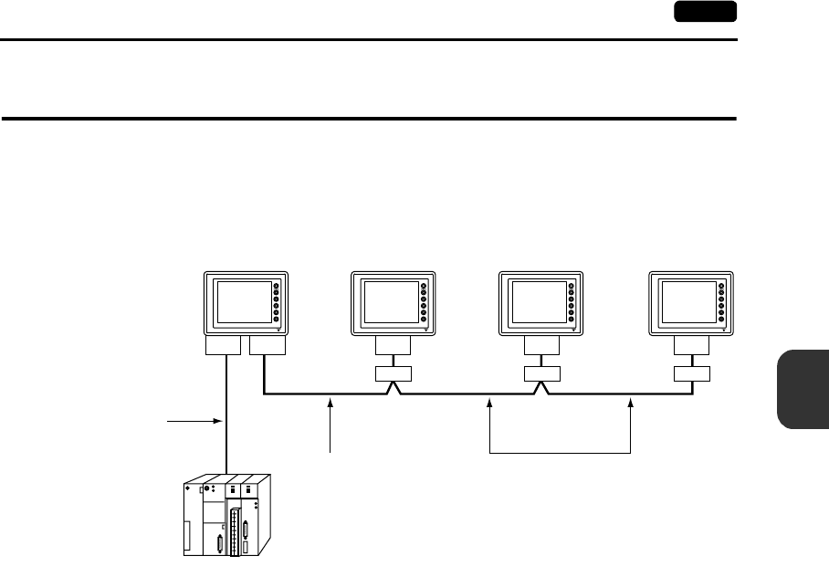
5
3. n : 1 Connection (Multi-link 2) 5-3
Connections
3. n : 1 Connection (Multi-link 2)
•One PLC is connected to a maximum of four UG230 units.
•An original network is created where the UG230 (Local Port 1) that is directly connected to the
PLC is the master station, and other three UG230 are slave stations. Only the master station
makes communications directly with the PLC, and the slave stations make communications with
the PLC via the master station.
•Communications between the UG230 master station and the PLC depend on the communication
speed set on the PLC. The maximum available speed for the UG230 is 115 kbps, which is higher
than the one available with multi-link connection described in “4. n : 1 Connection (Multi-link).”
•This multi-link connection is available with almost all the PLC models that support 1 : 1 connection.
(The connection between the master station and the PLC is the same as the one for 1 : 1
connection.)
•Use the RS-485 2-wire connection between stations of the UG230. Please use Fuji’s multi-link 2
master cable (UG00C-H) for connection between the master station (local port 1) and the slave
station (local port 2).
•The UG230, UG30 series and UG20 series can be used together. The UG20 series can be the
master station.
(However, when UG220/UG221 is the master station, the slave station must be UG220/UG221.
Also, depending on the hardware version of the UG20 series, multi-link 2 connection may not be
supported. Refer to the User’s Manual <UG20 series Hardware> (FEH352).
•For more information on wiring and communication settings, refer to the User’s Manual <PLC
Connection> (FEH380).
. . .
. . .
. . .
. . .
. . .
. . .
. . .
. . .
. . .
. . .
. . .
. . .
. . .
. . .
. . .
. . .
RUN
STOP
PLC
RS-232C
RS-422
RS-485
MJ2 MJ1 MJ2 MJ2 MJ2
Fuji’s cable
“UG00C-H” (3 m)
RS-485 connection
UG230 master UG230 slave UG230 slave
Local port
1
Local port
2
Local port
3
Local port
4
UG230 slave
*
* In the case of UG230 + UG230A-DCL, connect to “CN1”.
***
Terminal block Terminal block Terminal block
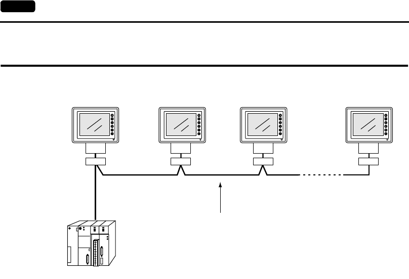
5-4 4. n : 1 Connection (Multi-link)
4. n : 1 Connection (Multi-link)
•One PLC is connected to multiple UG230 units. (Maximum connectable units: 32)
•The PLC must be of the type of signal level RS422/RS485 with port numbers.
RS422 connection between the UG230 ↔ PLC must be in 2-wire connection.
•The UG230, UG30 series and UG20 series can be used together.
•For more information on wiring and communication settings, refer to the User’s Manual <PLC
Connection> (FEH380).
. . .
. . .
. . .
. . .
. . .
. . .
. . .
. . .
. . .
. . .
. . .
. . .
. . .
. . .
. . .
. . .
RUN
STOP
PLC
MJ2 MJ2 MJ2 MJ2
Maximum length (PLC to the terminating UG230) = 500 m
RS-422/RS-485 connection
UG230 1 UG230 2 UG230 3 UG230 n (n = 1 to 32)
*
* In the case of UG230 + UG230A-DCL,
connect to “CN1”.
** *
Terminal block Terminal block Terminal block Terminal block
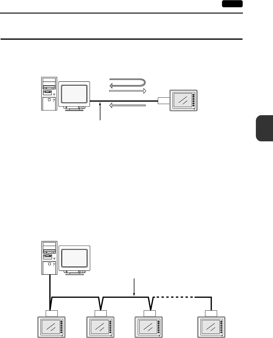
5
5. Universal Serial Communications 5-5
Connections
5. Universal Serial Communications
•A general purpose computer or an ASCII unit of the PLC (master station) controls the POD (slave
station) using dedicated commands.
•The UG230 internal user memory addresses ($u) must be used for memory allocation for switch,
lamp or data display parts.
When the master station specifies a screen number, data is written to the internal memory address
($u) allocated for the screen. If the screen is switched internally, the new screen number is read
and is written to the internal memory address ($u) allocated for the screen.
•For 1 : 1 connection, the UG230 can send an interrupt to the master station through switch
activation, write command from the keypad, and screen change.
•Use MJ2 (or CN1 when the UG230A-DCL is provided) of the UG230 for connection with a
general-purpose computer. Either signal level RS-232C or RS-422 (RS-485) can be selected.
•In addition to 1 : 1 connection, 1 : n connection is available between the general-purpose
computer and the UG230 via RS-422.
(A maximum of 32 UG230 units can be connected.)
For 1 : n connection, interrupts cannot be used.
•For more information, refer to the User’s Manual <PLC Connection> (FEH380).
RESET
disc
MJ2
RS-232C or RS-422 (RS-485)
UG230
Write
General-purpose
computer
Dedicated commands
Interrupt
Read
RESET
disc
MJ2 MJ2 MJ2 MJ2
RS-422 (RS-485) connection
UG230 1
General-purpose computer
UG230 2 UG230 3 UG230 n (n = 1 to 32)
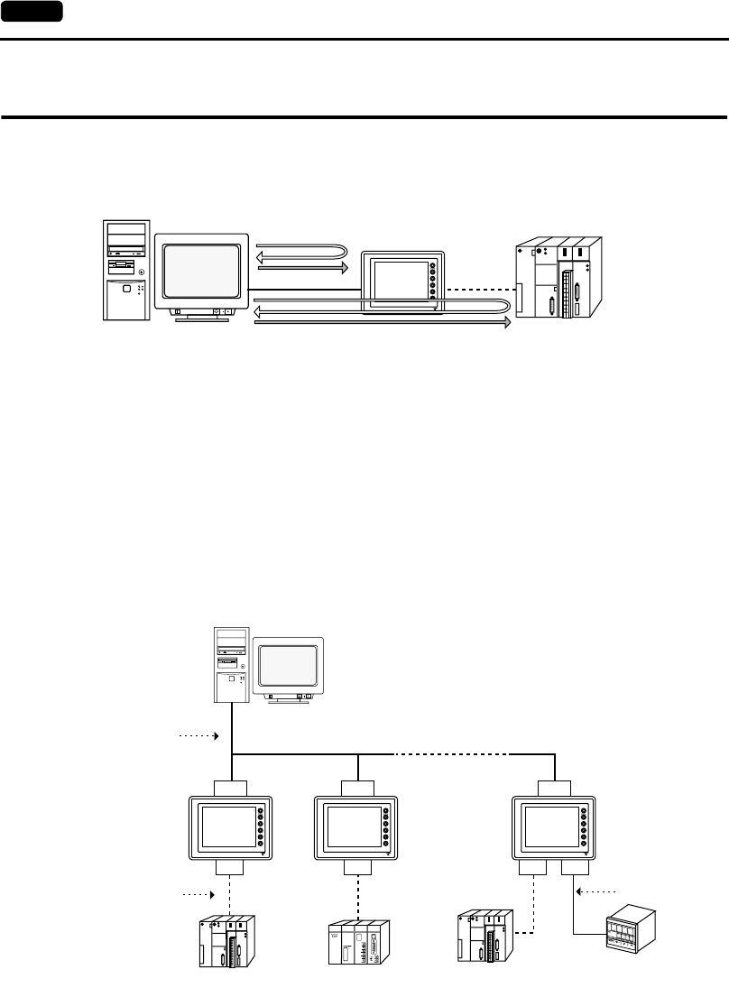
5-6 6. UG-Link
6. UG-Link
•“UG-Link” is the network where the computer reads from and writes to the internal memory of the
UG230, memory card, PLC memory or temperature control/PLC2 memory using a dedicated
protocol.
•Use MJ1 of the UG230 for connection with a general-purpose computer. Use MJ2 for
communications with the PLC.
When the option unit UG230A-DCL is installed, it is possible to use CN1 for communications with
the PLC, MJ2 for connection to the PLC using the temperature controller or PLC2Way, and MJ2 for
communications with a computer. Data of the PLC or temperature controller can be collected
through communications with the UG230. Data collection is available even between the products
of different manufacturers.
•Either signal level RS-232C or RS-485 can be selected.
With RS-232C, one UG230 unit can be connected; with RS-485, a maximum of 31 UG230 units
can be connected.
<RS-485 connection>
•For more information, refer to the User’s Manual <PLC Connection> (FEH380).
RESET
disc . . .
. . .
. . .
. . .
. . .
. . .
. . .
. . .
. . .
. . .
. . .
. . .
. . .
. . .
. . .
. . .
RUN
STOP
PLCPC UG230
Dedicated commands
Read
Write
PLC
RS-232C
RS-422
RS-485
PLC PLC
RS-485
RS-232C
RS-422
RS-485
MJ2 MJ2 CN1 MJ1
MJ1 MJ1 MJ2
RESET
disc
. . .
. . .
. . .
. . .
. . .
. . .
. . .
. . .
. . .
. . .
. . .
. . .
. . .
. . .
. . .
. . .
RUN
STOP
. . .
. . .
. . .
. . .
. . .
. . .
. . .
. . .
. . .
. . .
. . .
. . .
. . .
. . .
. . .
. . .
RUN
STOP
Temperature controller,
inverter or PLC
Local port
1
Local port
2
Local port
31
* [UG230 + UG230A-DCL]
*
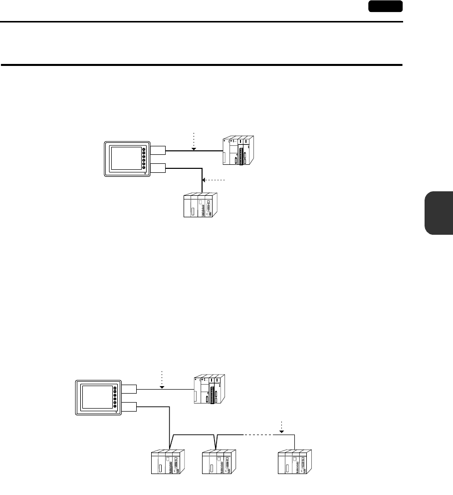
5
7. PLC2Way 5-7
Connections
7. PLC2Way
•The “PLC2Way” function is an original network function where one UG230 can be connected to
two PLCs. Even if the manufacturers of these PLCs are not the same, they can be connected to
one UG230.
•Connect the first PLC to MJ2 (or CN1 when the UG230A-DCL is provided), and the second PLC
(PLC2Way) to MJ1.
•With the PLC2Way function, it is possible to communicate with PLCs without special program in
the same way as 1 : 1 connection.
Two PLCs that are connected to the UG230 are controlled at the same time, and memory
read/write operations are available with these two PLCs.
•Connection at MJ1 (PLC2Way) can be performed via RS-232C or RS-485 (2-wire).
With RS-232C, one PLC can be connected; with RS-485, a maximum of 31 PLCs can be
connected.
•Periodical reading/sampling of PLC data on the PLC2Way side
When read/write memory addresses are preset on the temperature control network/PLC2Way
table, background data reading is performed at regular intervals. It is also possible to save the
read data in the UG230 internal buffer, SRAM or CF card.
•Data transfer between PLCs
The PLC memory data can be transferred to another PLC in blocks using a macro command.
•For more information, refer to the User’s Manual <PLC Connection> (FEH380).
run
PLC
RS-232C
RS-422/RS-485
RS-232C
RS-422/RS-485
PLC
MJ2
PROGRAMMER
FACTORY
ACE
MJ1
UG230
(Mitsubishi)
(2-wire connection)
(Yokogawa)
run
PLC
RS-232C
RS-422/RS-485
MJ2
MJ1
RS-422/RS-485
PLC1
PROGRAMMER
FACTORY
ACE
PLC2
PROGRAMMER
FACTORY
ACE
PLCn n = 1 ~ 31
PROGRAMMER
FACTORY
ACE
UG230
(2-wire connection)
(n = 1 to 31)
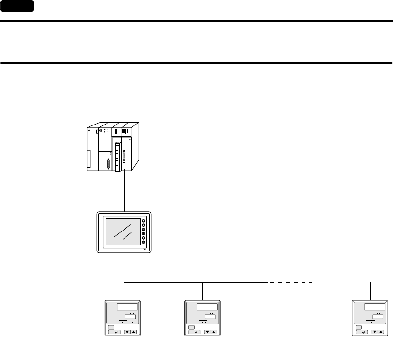
5-8 8. Temperature Control Network
8. Temperature Control Network
•Using the temperature control network, the UG230 can be connected to the temperature controller
or inverter.
With RS-232C, one PLC can be connected; with RS-485, a maximum of 31 temperature
controllers can be connected.
•Data of temperature controllers connected to the UG230 can be set or monitored.
•Periodical reading/sampling of temperature controller data
When read/write memory addresses are preset on the temperature control network/PLC2Way
table, background data reading is performed at regular intervals. It is also possible to save the
read data in the UG230 internal buffer, SRAM or CF card.
•Data transfer
It is also possible to transfer data in the PLC memory, UG230 internal memory or a memory card
to the temperature controller at one time using a macro command. Conversely, data in the
temperature controller can be transferred to the PLC memory, UG230 internal memory or a
memory card at one time.
•For more information, refer to the User’s Manual <Temperature Control Network> (FEH365).
A/M
SET/ENT
PV
SP
SP2 3 4
AL1 2 3 MAN
100
90
A/M
SET/ENT
PV
SP
SP2 3 4
AL1 2 3 MAN
100
90
A/M
SET/ENT
PV
SP
SP2 3 4
AL1 2 3 MAN
100
90
A/M
SET/ENT
PV
SP
SP2 3 4
AL1 2 3 MAN
100
90
A/M
SET/ENT
PV
SP
SP2 3 4
AL1 2 3 MAN
100
90
12n
(
Max
= 31)
UG230
PLC
Temperature
controller
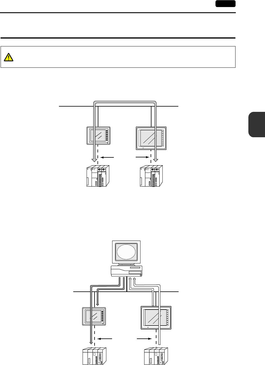
5
9. Ethernet 5-9
Connections
9. Ethernet
•Transferring data in memory
Data in memory can be transferred to the UG230 on the Ethernet or to the PLCs linked to the
UG230 as a host by using macro commands (EREAD/EWRITE).
•Communications between the server and the UG230
- “HKEtn10.dll” (for UDP/IP protocol) is provided so that the user can create an original
application by using Visual C++ or Visual Basic, etc. to allow the server to access the memory
device, such as UG230 internal memory, memory card or the PLC memory linked with the
UG230 as a host........ (a)
- The macro command (SEND) enables the UG230 to access the server........ (b)
CAUTION
To perform Ethernet communications on the UG230, the option unit UG230A-DCL must
be installed.
<PLC>
Ethernet
<UG230>
RS-232C
RS-485
F1
F2
F3
F4
F5
F6
F7
SYSTEM
POWER
<PLC>
Ethernet
<UG230>
RS-232C
RS-485
PROGRAMMER
(a) (b)
PROGRAMMER
F1
F2
F3
F4
F5
F6
F7
SYSTEM
POWER
Server
Application
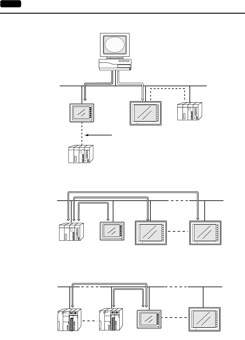
5-10 9. Ethernet
- Screen data can be transferred from the UG00S-CW editor on the server to the UG230.
•Communications between the Ethernet-ready PLC and the UG230
- The UG230 can communicate with the PLC on the Ethernet.
- The UG230 can communicate with multiple PLCs on the Ethernet.
•For more information, refer to the User’s Manual <PLC Connection> (FEH380).
<PLC>
Ethernet
<UG230>
RS-232C
RS-485
UG00S-CW
PROGRAMMER
PROGRAMMER
F1
F2
F3
F4
F5
F6
F7
SYSTEM
POWER Ethernet-ready PLC
Server
<PLC:1>
Ethernet
<UG230:2> <UG230:n>
<UG230:1>
PROGRAMMER
FACTORY
ACE
F1
F2
F3
F4
F5
F6
F7
SYSTEM
POWER
F1
F2
F3
F4
F5
F6
F7
SYSTEM
POWER
* Ethernet-ready PLC only
<PLC:1>
Ethernet
<UG230:1> <UG230:n>
<PLC:n>
F1
F2
F3
F4
F5
F6
F7
SYSTEM
POWER
* Ethernet-ready PLC only

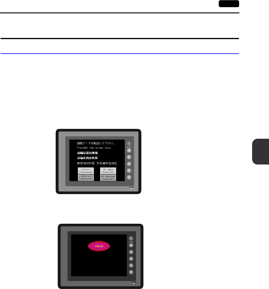
6
1. Operational Procedures 6-1
POD Operations
1. Operational Procedures
POD Operation
Follow the procedure below to operate the POD.
1. Installation and wiring
For details, refer to Chapter 3.
2. Connection with devices including a PLC and a temperature controller
For instructions and precautions on wiring between the POD and other devices, refer to the
separate User’s Manual <PLC Connection> (FEH380).
3. POD power-on
•New POD
•Other than the above
When the check screen below and then the next user screen are displayed correctly, go to
step 5.
4. Screen data creation and transfer
•New POD
Refer to “Initial Screen” (page 6-2).
•Other than the above
Refer to Chapter 5, “Data Transference” in User’s Manual <Operation> (FEH375).
5. Operation start
The POD becomes operable with a PLC or a computer connected to it.
* If the POD does not operate normally and shows an error message, eliminate the cause by
referring to Chapter 7.
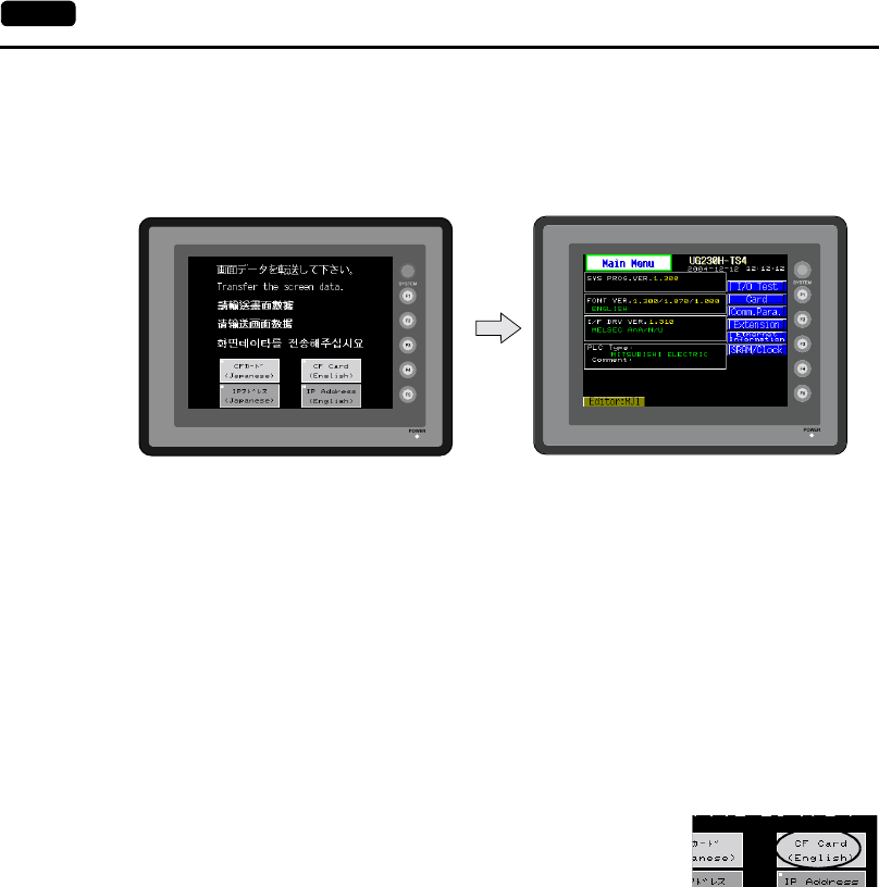
6-2 1. Operational Procedures
Initial Screen
When the power of POD is turned on for the first time, the Main Menu screen shown below on the left
is displayed.
Transferring Screen Data for the First Time
There are some methods for transferring screen data for the first time.
•UG230 only
1. Transferring screen data via the UG00C-T or USB cable
Transfer screen data from the computer while the initial screen is displayed.
2. Transfer screen data from a CF card (USB CF card reader/writer) or a memory card
(UG00P-MR).
1) Transfer screen data from the computer to the desired card.
2) Connect a USB CF card reader/writer or a UG00P-MR to the UG230, and insert the card.
3) Press the [CF Card (English)] switch. The “Card Menu” screen
is displayed.
4) Follow the instructions as described in “Card Menu Screen”
(page 6-15) and transfer screen data.
Initial screen displayed when power is turned
on for the first time
Main Menu screen after transferring screen
data

6
1. Operational Procedures 6-3
POD Operations
•UG230 + UG230A-DCL (option unit)
1. Transferring screen data via the UG00C-T or USB cable
Transfer screen data from the computer while the initial screen is displayed.
2. Transfer screen data from a CF card.
1) Transfer screen data from the computer to a CF card.
2) Insert the CF card into the option unit.
3) Press the [CF Card (English)] switch. The “Card Menu” screen
is displayed.
4) Follow the instructions as described in “Card Menu Screen”
(page 6-15) and transfer screen data.
3. Transferring screen data via Ethernet
1) Press the [IP Address (English)] switch.
2) The “Ethernet” screen is displayed.
Follow the instructions as described in “Ethernet (Optional)”
(page 6-29) and set the IP address.
Press the [Setting Finished] switch. The initial screen is displayed again.
3) Transfer screen data from the computer via Ethernet.
•Auto-uploading screen data from the CF card to the UG230
1) Transfer screen data from the computer to a CF card.
2) Turn the UG230 off. Set the DIPSW1 on the UG230 to the ON position, and insert the CF
card into the USB CF card reader/writer or the option unit.
3) Turn the UG230 on. The screen data is automatically uploaded from the CF card to the
UG230.
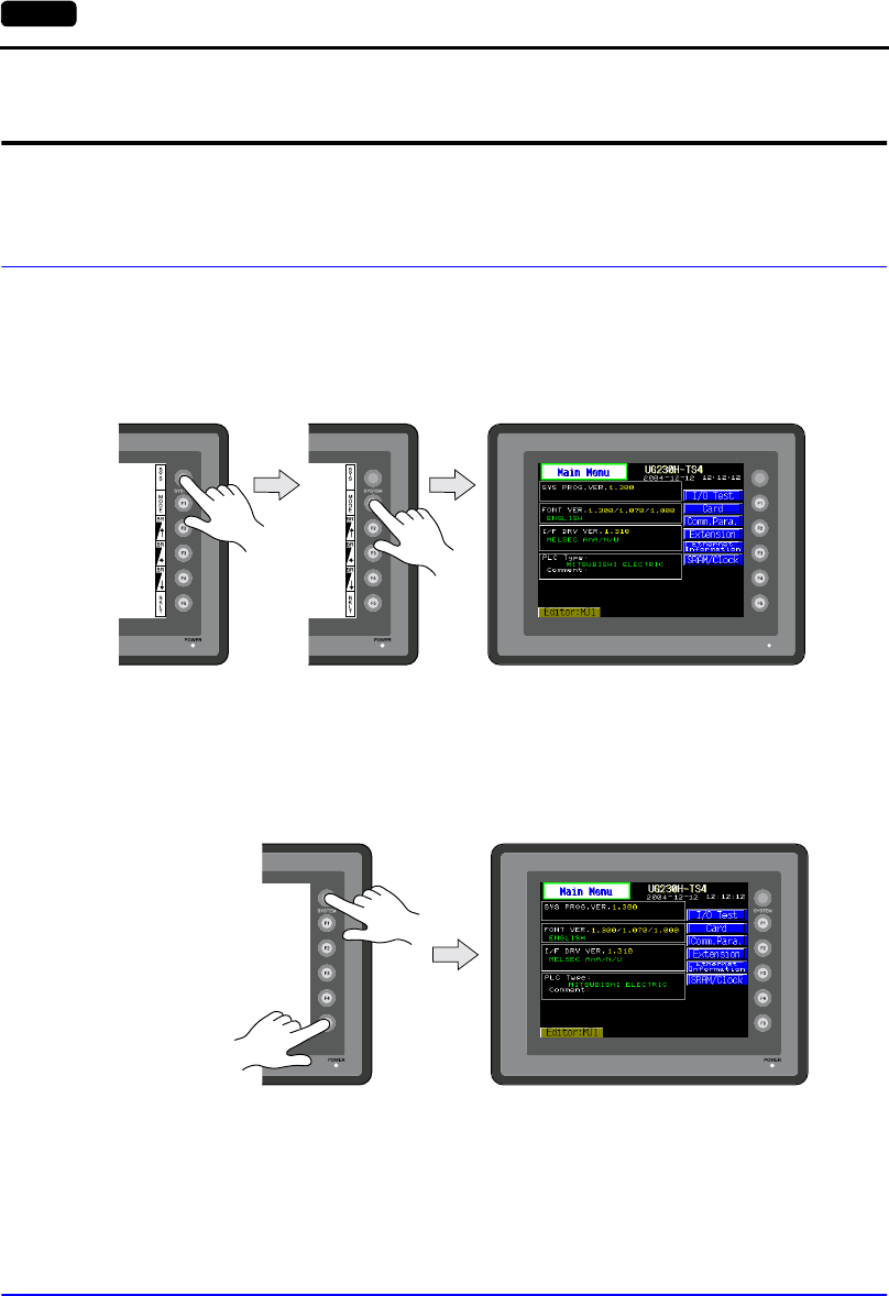
6-4 2. Main Menu Screen
2. Main Menu Screen
The Main Menu screen is displayed when the POD is in the STOP mode. In this state, the POD is
disconnected from the PLC and other external devices.
Displaying the Main Menu Screen
In the RUN Mode
To bring up the Main Menu screen in the RUN mode, press the [SYSTEM] switch and then the [F1]
switch while the vertical menu is displayed.
When the [SYSTEM] switch is disabled:
Pressing the [SYSTEM] switch does not bring up the vertical menu.
In this case, press the [SYSTEM] and [F5] switches at the same time. (If the time for simultaneous
pressing of these switches is preset, hold down the switches for the required time.)
When the [MODE] (F1) switch is disabled:
When the vertical menu is displayed by the [SYSTEM] switch, the [MODE] (F1) switch does not work.
In this case, press the [MODE] (F1) and [F5] switches at the same time. (If the time for simultaneous
pressing of these switches is preset, hold down the switches for the required time.)
Moving Back to the Screen in the RUN Mode
Press the [SYSTEM] switch and the [F1] switch.
Main Menu screen
Main Menu screen
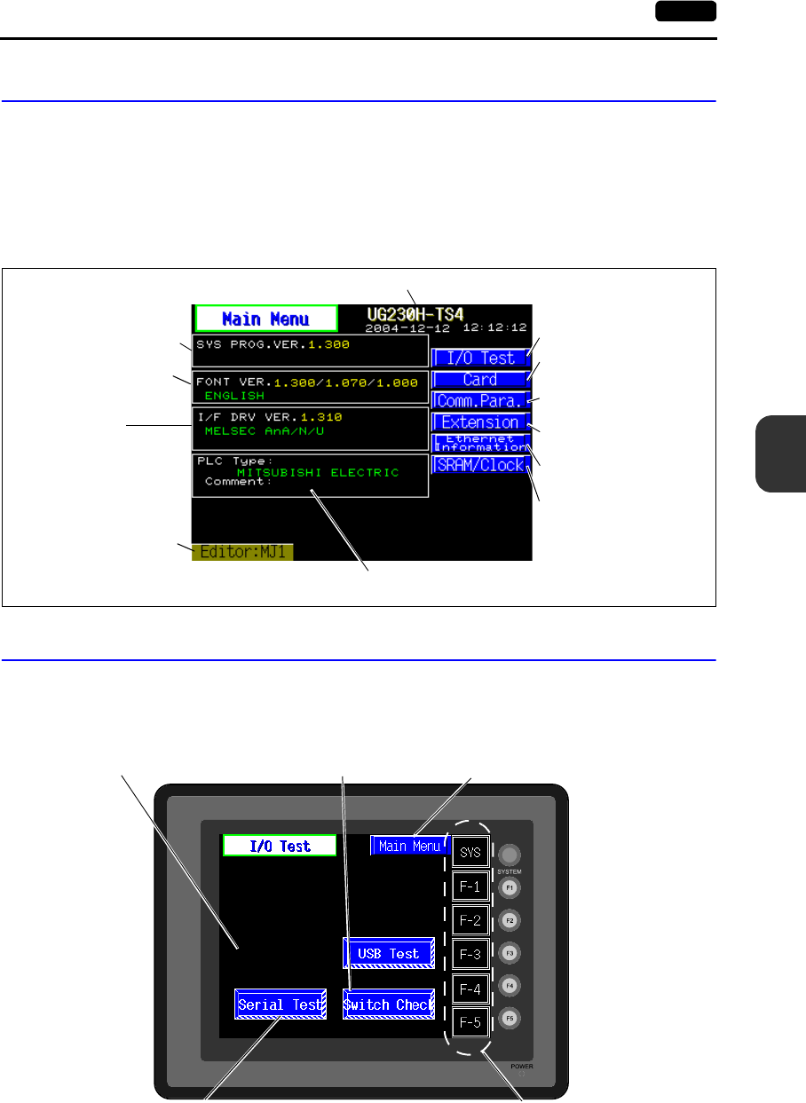
6
2. Main Menu Screen 6-5
POD Operations
Main Menu Screen
•The Main Menu screen indicates the UG230 model, system information, and screen data
information.
•The Main Menu screen is the system menu screen for transferring screen data between a
personal computer and the UG230.
When transferring screen data from a personal computer to the UG230, this Main Menu screen
must be displayed. (However, if [Editor Port] is selected for [Modular Jack 1] or on-line editing is
used, it is not necessary to bring up this screen.)
1. I/O Test
When the [I/O Test] switch on the Main Menu screen is pressed, the following “I/O Test” screen
appears. This screen is used to check that there is no problem with the UG230 interfaces and touch
switch operation.
Font data versions,
country/local/font
UG230 model
System program version
PLC I/F driver version
and model
Communication parameter
(See page 6-27.)
Port name used
for data transfer
PLC model and file comment set
for the screen data file
I/O Test (See page 6-5.)
Card Menu (See page 6-15.)
Extension (See page 6-28.)
Ethernet (See page 6-29.)
SRAM/Clock (See page 6-36.)
Performs a USB-A (master port)
connection test. (See page 6-6.)
Moves to the “Touch Switch” screen.
(See page 6-13.) The Main Menu screen is displayed again.
(See page 6-5.)
Performs a CN1/MJ1/MJ2 interface test.
(See page 6-7.)
Performs a function switch test.
(See page 6-13.)
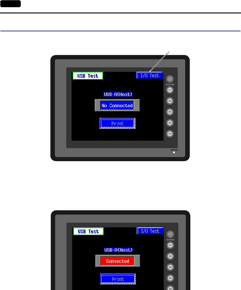
6-6 2. Main Menu Screen
1-1. USB Test
When the [USB Test] switch is pressed, the following screen is displayed.
This screen is used to check the status of USB-A (master port) connection.
Checking the Connection Status
If the lamp on the screen shows [No Connected] in blue, the device has not been connected to the
USB port correctly.
When the lamp shows [Connected] in red, the device is connected to the USB port correctly.
Moves back to the “I/O Test” screen.
(See page 6-5.)
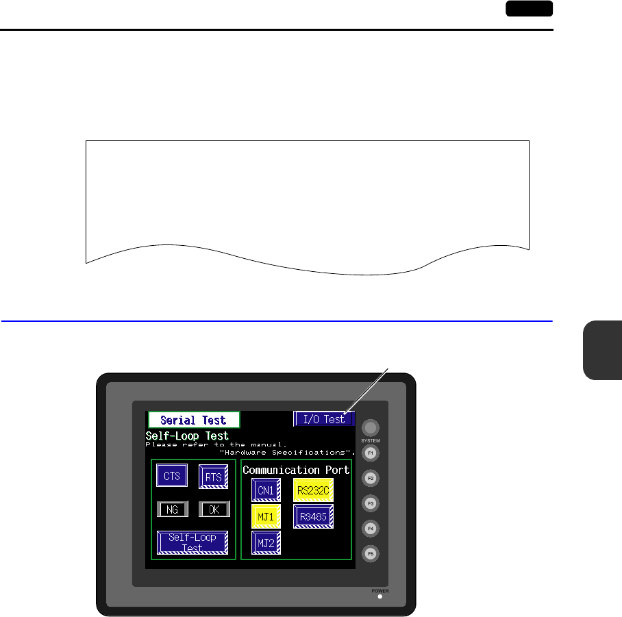
6
2. Main Menu Screen 6-7
POD Operations
Printer Test
When a printer is connected to the USB-A port, a print test can be done.
Check if the UG230 sends signals normally to the printer using the [Print] switch. The test is
successful if a test page is printed without problems.
Example:
1-2. Serial Connection Test
When the [Serial Test] switch is pressed, the following screen is displayed.
This is a signal test for communications through the MJ1, MJ2 or CN1 connector.
Perform this test if the communication is not successful when transferring screen data through MJ1,
connecting the PLC using MJ2 or CN1, or selecting multi-link 2, temperature controller/PLC2Way or
PLC for MJ1, or connecting the card recorder or serial extension I/O.
!"#$%&@ 0123456789 ABCDEFGHIJKLMNO
!"#$%&@ 0123456789 ABCDEFGHIJKLMNO
!"#$%&@ 0123456789 ABCDEFGHIJKLMNO
!"#$%&@ 0123456789 ABCDEFGHIJKLMNO
!"#$%&@ 0123456789 ABCDEFGHIJKLMNO
!"#$%&@ 0123456789 ABCDEFGHIJKLMNO
!"#$%&@ 0123456789 ABCDEFGHIJKLMNO
Moves back to the “I/O Test” screen.
(See page 6-5.)
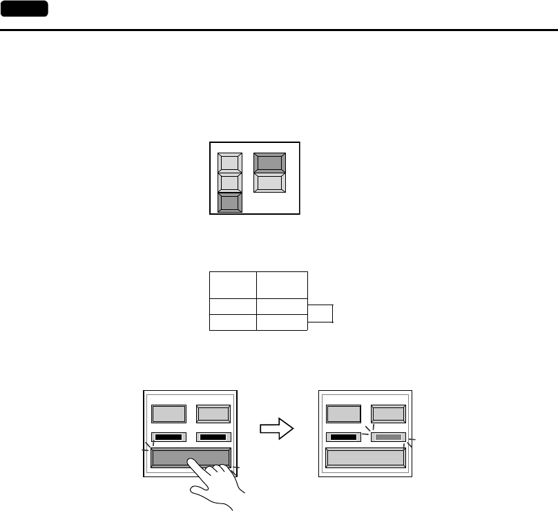
6-8 2. Main Menu Screen
MJ2 Test
RS-232C signal test
1. Slide the slide switch on the POD to the upper position for RS-232C.
2. Turn on the [MJ2] and [RS232C] switches under [Communication Port].
3. Check the signals [RD] and [SD]. Wire inside MJ2 as shown below.
4. Press the [Self-Loop Test] switch. When the [OK] lamp lights up, the test is successfully
completed.
* If the [NG] lamp lights up, consult your local distributor.
Communication Port
CN1
MJ1
MJ2
RS232C
RS485
Signal
Name Pin No.
RD 7
SD 8
MJ2
Self-Loop
Test
CTS RTS
NG OK
CTS RTS
NG OK
Self-Loop
Test
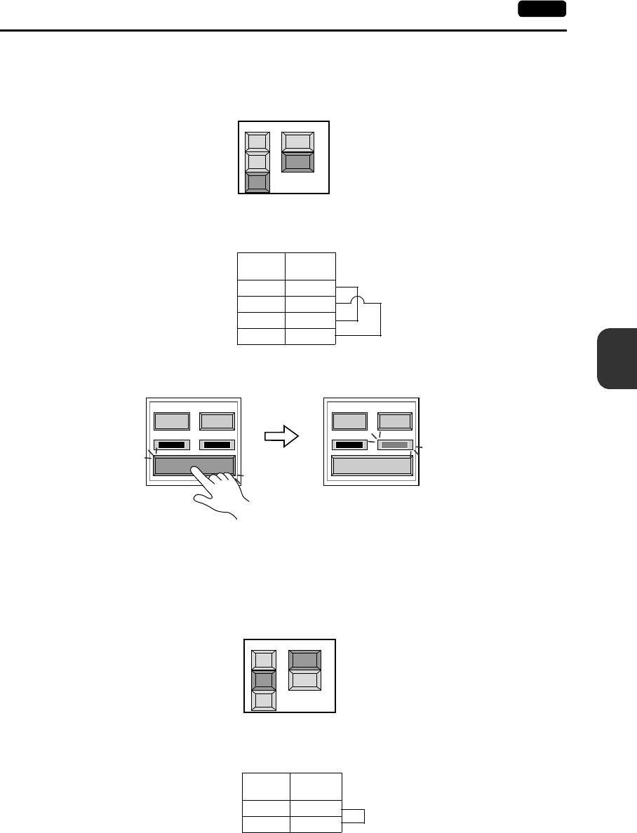
6
2. Main Menu Screen 6-9
POD Operations
RS-422 signal test
1. Slide the slide switch on the POD to the lower position for RS-422.
2. Turn on the [MJ2] and [RS485] switches under [Communication Port].
3. Check the signals [+RD], [−RD], [+SD] and [−SD]. Wire inside MJ2 as shown below.
4. Press the [Self-Loop Test] switch. When the [OK] lamp lights up, the test is successfully
completed.
* If the [NG] lamp lights up, consult your local distributor.
MJ1 Test
RS-232C signal test
1. Turn on the [MJ1] and [RS232C] switches under [Communication Port].
2. Check the signals [RD] and [SD]. Wire inside MJ1 as shown below.
RS232C
RS485
Communication Port
CN1
MJ1
MJ2
Signal
Name Pin No.
+SD 1
−SD 2
+RD 7
−RD 8
MJ2
Self-Loop
Test
CTS RTS
NG OK
CTS RTS
NG OK
Self-Loop
Test
CN1
MJ1
MJ2
RS232C
RS485
Communication Port
Signal
Name Pin No.
RD 7
SD 8
MJ1
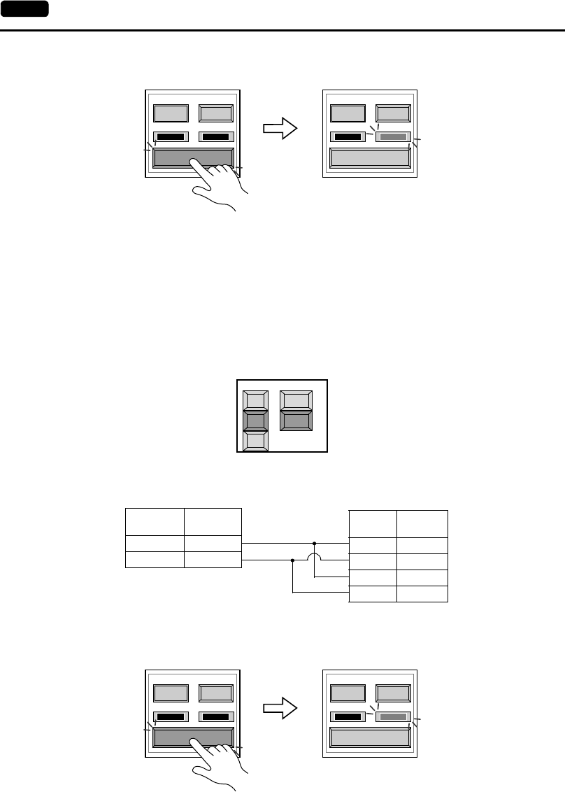
6-10 2. Main Menu Screen
3. Press the [Self-Loop Test] switch. When the [OK] lamp lights up, the test is successfully
completed.
* If the [NG] lamp lights up, consult your local distributor.
RS-485 signal test
MJ1 must be connected to MJ2 for an RS-485 signal test through MJ1. Therefore, perform a serial
connection test to check that there is no problem with MJ2 before conducting an MJ1 test.
1. Slide the slide switch on the POD to the lower position for RS-422.
2. Turn on the [MJ1] and [RS485] switches under [Communication Port].
3. Check the signals [+RD], [-RD], [+SD] and [-SD]. Connect MJ1 and MJ2 as illustrated below.
4. Press the [Self-Loop Test] switch. When the [OK] lamp lights up, the test is successfully
completed.
* If the [NG] lamp lights up, consult your local distributor.
Self-Loop
Test
CTS RTS
NG OK
CTS RTS
NG OK
Self-Loop
Test
Communication Port
CN1
MJ1
MJ2
RS232C
RS485
Signal
Name Pin No.
+SD 1
−SD 2
+RD 7
−RD 8
MJ2
Signal
Name Pin No.
+RD/+SD 1
−RD/−SD 2
MJ1
Self-Loop
Test
CTS RTS
NG OK
CTS RTS
NG OK
Self-Loop
Test
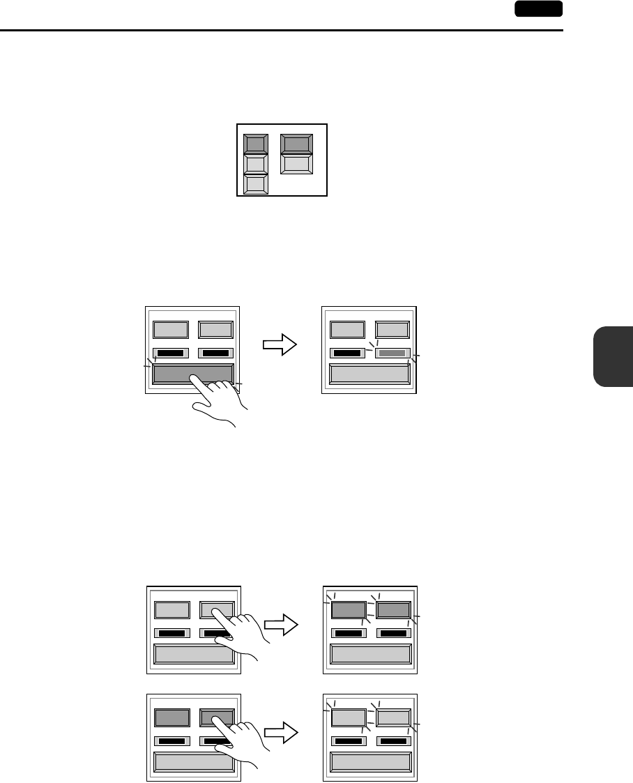
6
2. Main Menu Screen 6-11
POD Operations
CN1 Test (with the option unit)
RS-232C signal test
Turn the [CN1] and [RS232C] switches on.
•SD/RD Test
Check the signals [SD] and [RD].
1. Install a jumper between pins 2 and 3 of CN1 on the backside of the UG230.
2. Press the [Self-Loop Test] switch. When the [OK] lamp lights up, the test is successfully
completed.
* If the [NG] lamp lights up, consult your local distributor.
•CTS/RTS Test
Check the signals [CTS] and [RTS].
1. Install a jumper between pins 4 (RTS) and 5 (CTS) of CN1 on the backside of the UG230.
2. Press the [RTS] switch and check that both [RTS] and [CTS] lamps light up at the same time.
Press the [RTS] switch again and check that both [RTS] and [CTS] lamps go off at the same
time.
CN1
MJ1
MJ2
RS232C
RS485
Communication Port
Self-Loop
Test
CTS RTS
NG OK
CTS RTS
NG OK
Self-Loop
Test
CTS RTS
NG OK
CTS RTS
NG OK
CTS RTS
NG OK
CTS RTS
NG OK
Self-Loop
Test
Self-Loop
Test
Self-Loop
Test
Self-Loop
Test
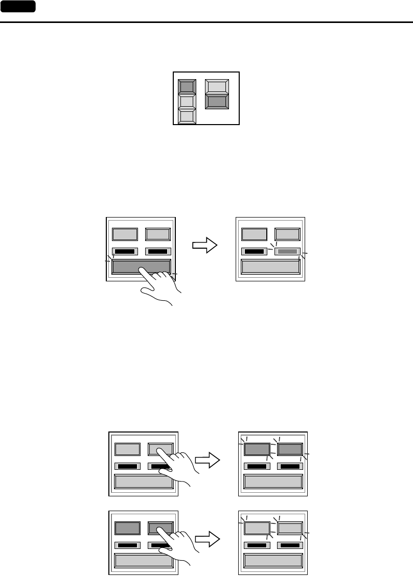
6-12 2. Main Menu Screen
RS-485 signal test
Turn the [CN1] and [RS485] switches on.
•SD/RD Test
Check the signals [SD] and [RD].
1. Install a jumper between pins 12 and 24 and between pins 13 and 25 of CN1 on the backside
of the UG230.
2. Press the [Self-Loop Test] switch. When the [OK] lamp lights up, the test is successfully
completed.
* If the [NG] lamp lights up, consult your local distributor.
•CTS/RTS Test
Check the signals [CTS] and [RTS].
1. Install a jumper between pins 14 (+RTS) and 19 (+CTS) of CN1 and between pins 17 (−RTS)
and 18 (−CTS) on the backside of the UG230.
2. Press the [RTS] switch and check that both [RTS] and [CTS] lamps light up at the same time.
Press the [RTS] switch again and check that both [RTS] and [CTS] lamps go off at the same
time.
CN1
MJ1
MJ2
Communication Port
RS232C
RS485
Self-Loop
Test
CTS RTS
NG OK
CTS RTS
NG OK
Self-Loop
Test
CTS RTS
NG OK
CTS RTS
NG OK
CTS RTS
NG OK
CTS RTS
NG OK
Self-Loop
Test
Self-Loop
Test
Self-Loop
Test
Self-Loop
Test
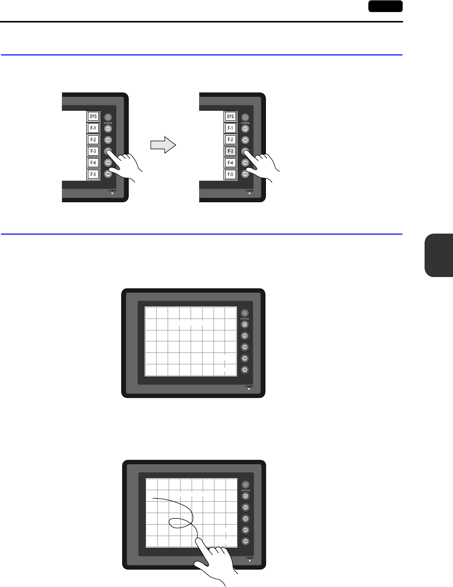
6
2. Main Menu Screen 6-13
POD Operations
1-3. SYSTEM & Function Switch Test
Check operations of six switches provided vertically on the right side of the panel.
Press the switch, and check that the lamp on the screen lights up while the switch is held down.
1-4. Touch Switch Test
If a touch switch does not activate at all or if an operation is performed without pressing any touch
switch, check that the touch switches on the UG230 panel are working properly.
1. Press the [Switch Check] switch. Grids appear on the screen as shown below.
2. Press a position on the panel, and check that the pressed position turns white.
The switch is activated normally when the pressed position turns white.
To move back to the “I/O Test” screen, press the [F4] switch.
To delete white dots press the [F5] switch.
3. If a position different from the pressed position turns white, refer to “Touch Switch Adjustment” on
the next page and adjust the touch switch position.
Erase
Return
X: Y:
Erase
Return
X: 180 Y: 206
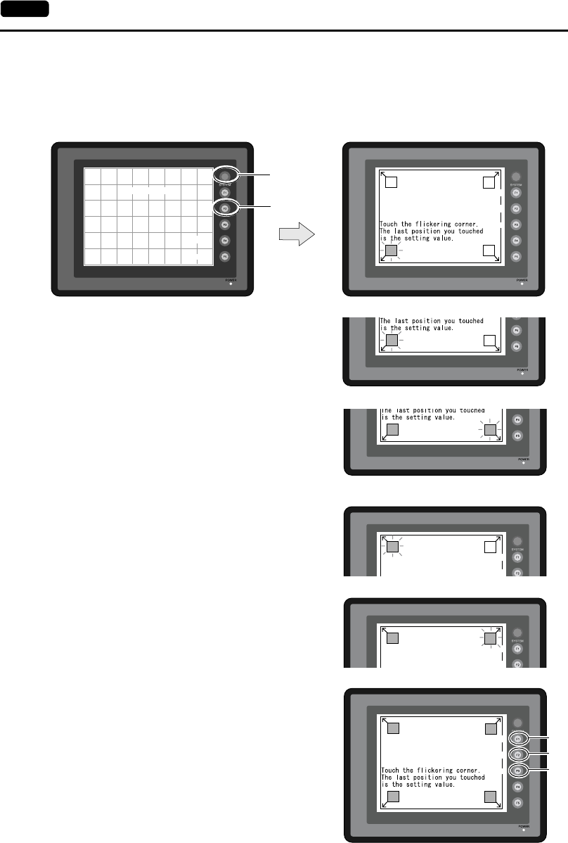
6-14 2. Main Menu Screen
Touch Switch Adjustment
If a position different from the pressed position turns white on the touch switch test screen, follow the
steps described below to adjust the touch switch position.
1. Hold down the [SYSTEM] switch and press the [F2] switch on the touch switch test screen.
2. Press on “1” that is flashing at the corner on the
touch switch adjustment screen. When the finger
is released, a beep sounds and the position is set.
“2” flashes.
3. Press on “2” that is flashing at the corner. When
the finger is released, a beep sounds and the
position is set. “3” flashes.
4. Press on “3” that is flashing at the corner. When
the finger is released, a beep sounds and the
position is set. “4” flashes.
5. Press on “4” that is flashing at the corner. When
the finger is released, a beep sounds and the
position is set.
6. To re-set the positions, press the [F2] switch and
follow step 2 and later.
7. Press the [F1] switch. A long beep sounds and
the positions are determined. The touch switch
test screen is displayed again.
8. To cancel the setting, press the [F3] switch. The
touch switch test screen is displayed again.
Erase
Return
X: Y:
Touch Switch Adjustment
34
12
Fix
Reset
Return
X: Y:
SYSTEM
F2
12
12
34
Fix
Reset
X: Y:
Touch Switch Adjustment
4
Fix
Reset
X: Y:
Touch Switch Adjustment
3
4
1
Fix
Reset
Return
X: Y:
2
Touch Switch Adjustment
3
F1
F2
F3
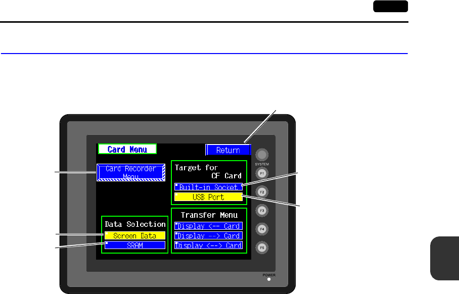
6
2. Main Menu Screen 6-15
POD Operations
2. Card Menu Screen
When the [Card Menu] switch on the Main Menu screen is pressed, the following “Card Menu” screen
appears.
This screen is used to transfer screen data between the UG230 and a CF card or a memory card.
1. [Card Recorder Menu] switch
Press this switch when connecting the card recorder to the MJ port of the UG230 and transferring
screen data between the UG230 and a memory card.
2. [Screen Data] switch
Press this switch when transferring screen data between the UG230 and a CF card.
3. [SRAM] switch
Press this switch when saving backup copies of the SRAM memory or when uploading the backup
data from the CF card to the UG230.
4. [Built-in Socket] switch
The CF card insertion position can be selected. If using a CF card while the option unit is
mounted, press this switch.
5. [USB Port] switch
The CF card insertion position can be selected. If using a CF card while a CF card reader/writer
(commercially available) is connected to the USB-A (master port), press this switch.
The Main Menu screen is displayed again.
1.
2.
3.
4.
5.
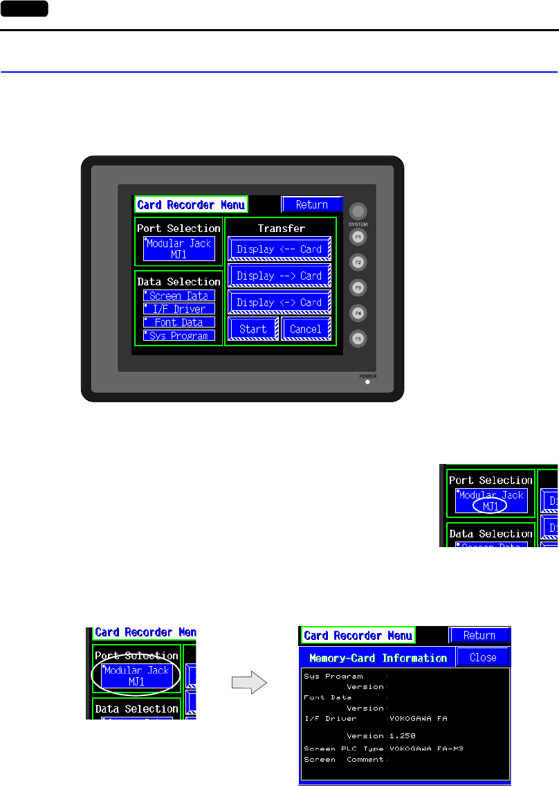
6-16 2. Main Menu Screen
2-1. Card Recorder Menu Screen
When the [Card Recorder Menu] switch on the “Card Menu” screen is pressed, the following “Card
Recorder Menu” screen appears.
This screen is used to transfer screen data between the UG230 and a memory card.
The procedure for transferring data is described below.
1. Connecting the UG00P-MR
Connect the UG00P-MR using the attached cable to the MJ port that is displayed in the “Port
Selection” field.
•MJ1: Connect the UG00P-MR to the MJ1 port. Normally MJ1 is
selected.
•MJ2: Connect the UG00P-MR to the MJ2 port. Only when
[Memory Card] is selected for [Modular Jack 2], “MJ2” is
indicated in the “Port Selection” field.
2. Mounting the Memory Card
Insert a memory card in to the card recorder.
3. Memory Card Information
Press the [Modular Jack MJ1] switch.
The memory card information contained in the inserted memory card is indicated.
To move back to the previous screen, press the [Close] button.
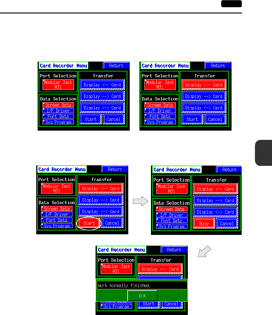
6
2. Main Menu Screen 6-17
POD Operations
4. Data Selection and Transfer Selection
In the “Transfer” field, select [Display <-- Card], [Display --> Card] or [Display <--> Card]. Press
the desired switch to turn the switch on. Multiple switches can be pressed in the “Data Selection”
field.
5. Starting Data Transfer
Press the [Start] switch. Data transfer is started. During data transfer, the [Start] switch changes
into [Busy] and flashes. When data is transferred, the following message is displayed.
Press the [OK] switch.
6. Press the [Return] switch. The “Card Menu” screen is displayed again.
Data selection Transfer selection
6-18 2. Main Menu Screen
2-2. Transferring Screen Data from a CF Card
CF Card Folder Configuration
Folders in the CF card are configured as shown below.
*1 These are access folders set by the UG00S-CW editor. Any folder name within eight 1-byte characters can be
given.
*2 These folders are automatically created when access folders are created. The folder names are fixed.
*3 The folder name for screen data auto uploading cannot be changed.
DAT0000 (access folder)
DSPDEF (screen data auto upload folder)
(Other folders are the same as access folders.)
DSP
CARD
SRAM
MEMO
RECIPE
SAMPLE
HDCOPY
BITMAP
JPEG
SNAP
WAV
FONT
WEBSERV
AAAAAAAA
BBBBBBBB
FFFFFFFF
DSPDEF DSP
*1 *2
DSP0000.BIN
MCMHEAD.BIN
MCMxxxx.BIN
SRM0000.BIN
MEMxxxx.BIN
RECxxxx.CSV
xxxxxxxx.CSV
BMPxxxx.BIN
VDxxxx.JPG
WAxxxx.WAV
DSPDEF.BIN
xxxx.FTD
*3
SMPxxxx.BIN
SMPxxxx.CSV
HDxxxx.JPG
HDxxxx.BIN
xxxx.JPG
JPxxxx.JPG
xxxxxxxx.SHT
xxxxxxxx.HTM
xxxxxxxx.TXT
CF card
Folder Name Folder Name File Name
Same as access folders
Folder Name Contents Folder Name Contents
BITMAP Saves pattern data (bitmap data) to reduce the
screen data capacity. RECIPE Reads and writes recipe data.
CARD Writes recipe data from the UG30 using the
UG20-compatible memory manager function. SAMPLE Saves history data of the data logging
function.
DSP Reads and writes screen data. SNAP Saves video snap images.
FONT Saves Gothic fonts or language data to reduce
the screen data capacity. SRAM Saves backup data of SRAM.
HDCOPY Writes hard copy images in the JPEG file format
from the UG30 (UG330H-SS only: BIN file). WAV Saves WAV files for sound output to reduce
the screen data capacity.
JPEG Saves JPEG files for display on the screen
(except for UG330H-SS). WEBSERV Saves files to be accessed from the Web
browser.
MEMO Saves memo pad data drawn with the UG30.
Folder Name Contents
DSP When setting the dipswitch on the POD and inserting a CF card, it automatically reads the screen data in this
folder.
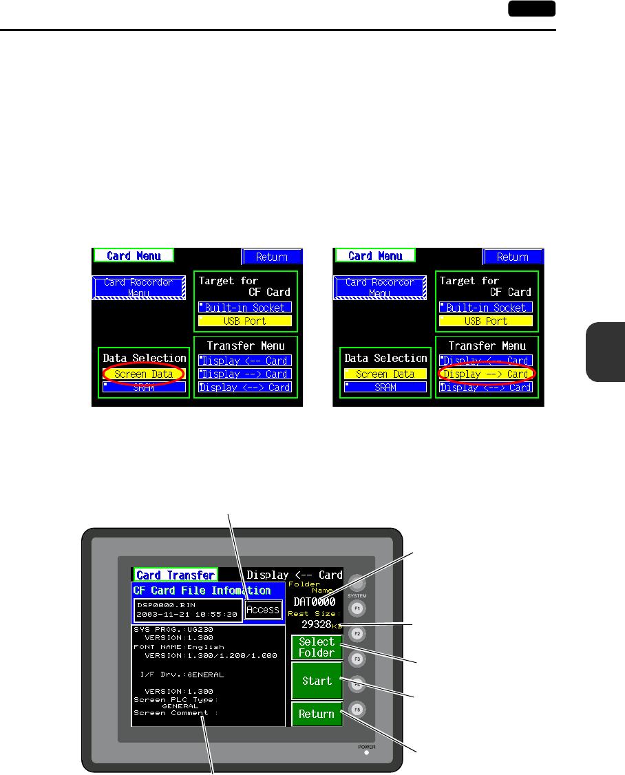
6
2. Main Menu Screen 6-19
POD Operations
Transferring Screen Data from a CF Card
The procedure of transferring data between the UG230 and a CF card is described below.
1. Mounting the CF Card
Insert the CF card into the CF card connector at the side of the UG230.
* Do not remove or insert the CF card in the later steps.
2. Data selection
Select [Screen Data]. When the lamp is red, it is selected.
3. Transfer selection
Select [Display <-- Card], [Display --> Card] or [Display <--> Card].
When [Display <-- Card] is Selected:
Transfer screen data from the computer to the CF card.
1. When [Display <-- Card] is selected, the following screen is displayed.
Data selection Transfer selection
Flashes during communication with the CF card.
Moves back to the previous
screen.
Indicates the free space
in the CF card.
Indicates the name of the
currently selected folder.
The access folder that is set
for screen data defaults.
If there is no screen data,
“DAT0000” defaults.
Indicates the information of the currently selected folder.
Starts transferring data
[Display <-- Card].
Used for checking or
renaming folder names.
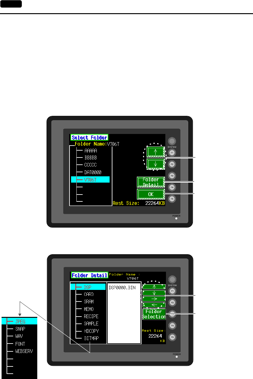
6-20 2. Main Menu Screen
2. Check the folder name, free space, and CF card file information. If the correct folder is selected,
move to step 4.
•Folder Name
Indicates the name of the currently selected folder.
The access folder that is set for screen data defaults.
If there is no screen data, “DAT0000” defaults.
•Rest Size
Indicates the free space in the CF card.
•CF Card File Information
Indicates the information of the currently selected folder.
3. To change to another folder, press the [Select Folder] switch.
The “Select Folder” screen is displayed.
•To see the details of the folder, press the [Folder Detail] switch.
The “Folder Detail” screen is displayed.
•Select the desired folder using the [↑]/[↓] switch, and press the [OK] switch.
The Card Transfer screen is displayed again and the CF card file information of the selected
file is indicated.
Moves the cursor.
Indicates the details
of the folder.
Determines the folder
selection.
Moves the cursor.
Moves back to the “Select
Folder” screen.
Scrolls with the
[↑]/[↓] switch.
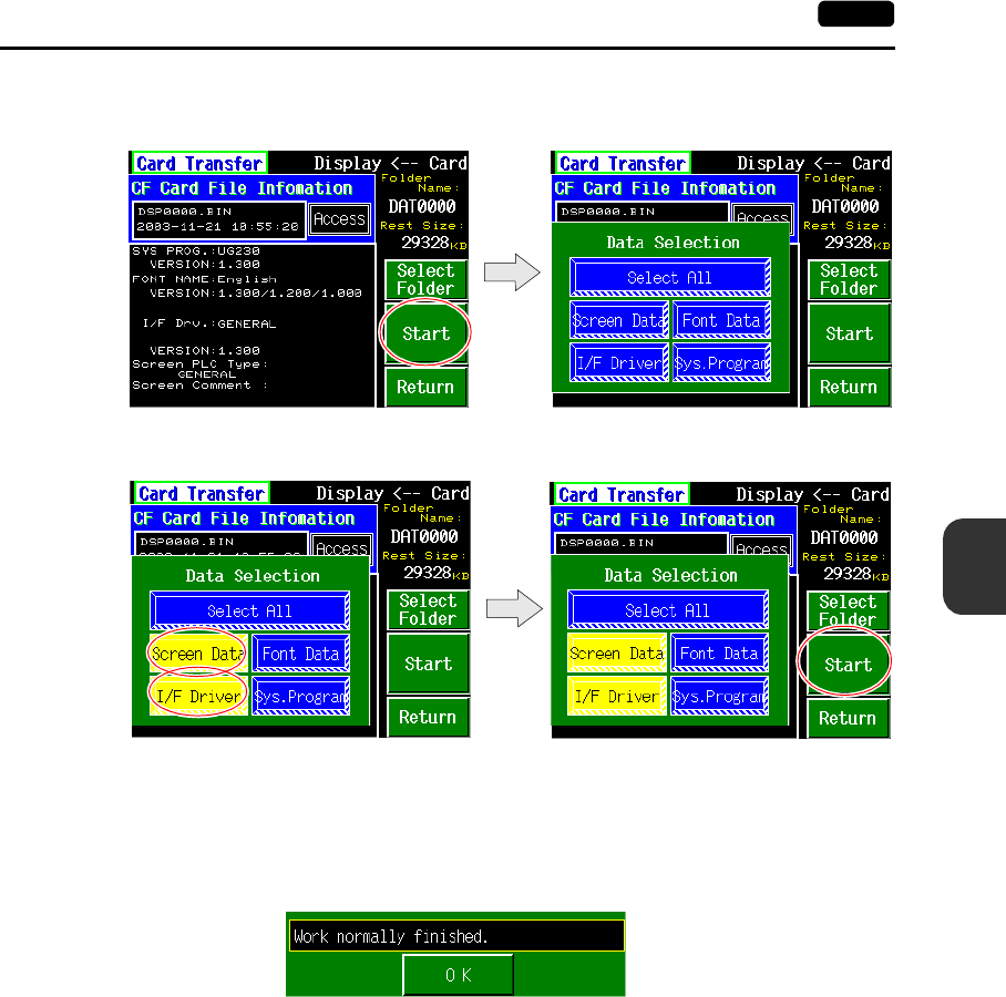
6
2. Main Menu Screen 6-21
POD Operations
4. Press the [Select Data] switch.
The [Data Selection] window is displayed and the [Select Data] switch changes to [Start].
Select the desired data, and press the [Start] switch.
To cancel the [Data Selection] window, press the [Return] switch.
5. During data transfer, the [Start] switch changes into [Busy] and flashes. When data has been
transferred successfully, the following window is displayed. However, when [Sys. Program] or
[Select All] is selected, the Main Menu screen is displayed without this message window on
completion of data transfer.
Press the [OK] switch.
The “Card Menu” screen is displayed.
If any other message is displayed, refer to page 6-26.
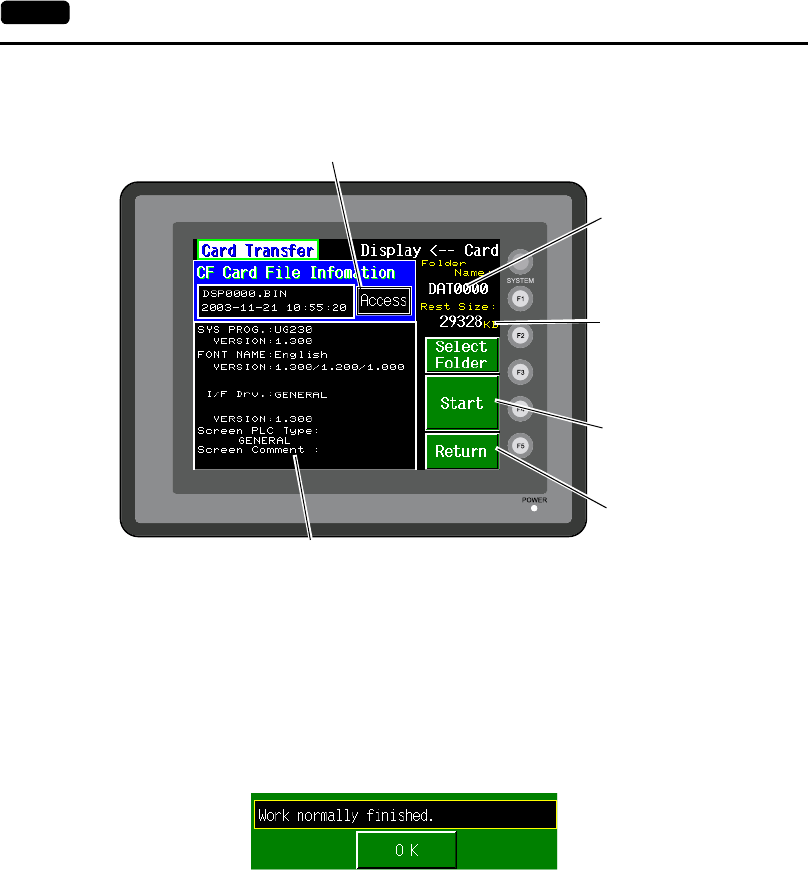
6-22 2. Main Menu Screen
When [Display --> Card] is Selected:
1. When [Display --> Card] is selected, the “Card Transfer” screen is displayed.
2. Check the folder name and CF card file information, and press the [Start] switch.
* When the access folder name of screen data is the same as that in the CF card, the CF card
file information is indicated on the screen, and data in the unit overwrites the CF card data.
Note that the CF card data is lost when data in the unit overwrites.
When the CF card file information is blank, a new file “DSP0000.BIN” is created in the DSP
folder.
3. During data transfer, the [Start] switch changes into [Busy] and flashes. When data has been
transferred successfully, the following window is displayed.
Press the [OK] switch. The CF card file information shows data that has been transferred.
If any other message is displayed, refer to page 6-26.
4. Press the [Return] switch. The “Card Menu” screen is displayed again.
Indicates the information of the currently selected folder.
If there is no screen data, this field becomes blank.
Flashes during communication with the CF card.
Moves back to the previous
screen.
Indicates the free space
in the CF card.
Indicates the name of the
currently selected folder.
Starts transferring data
[Display --> Card].
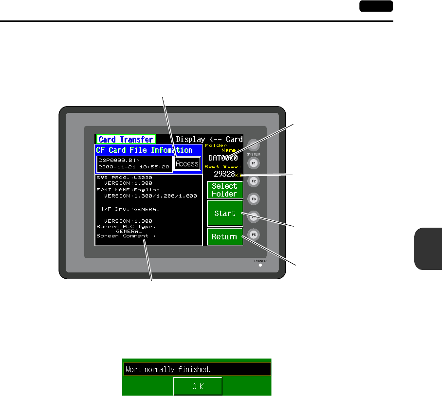
6
2. Main Menu Screen 6-23
POD Operations
When [Display <--> Card] is Selected:
1. When [Display <--> Card] is selected, the “Card Transfer” screen is displayed.
Screen data used for comparison is that in the DSP folder under the folder having the same name
as the access folder that is set by the UG00S-CW editor.
2. Press the [Start] switch.
3. During data transfer, the [Start] switch changes into [Busy] and flashes. When data has been
transferred successfully, the following window is displayed.
Press the [OK] switch.
If any other message is displayed, refer to page 6-26.
4. Press the [Return] switch. The “Card Menu” screen is displayed again.
Flashes during communication with the CF card.
Moves back to the previous
screen.
Indicates the free space
in the CF card.
Indicates the name of the
currently selected folder.
Starts transferring data
[Display --> Card].
Indicates the information of the currently selected folder.
If there is no screen data, this field becomes blank.
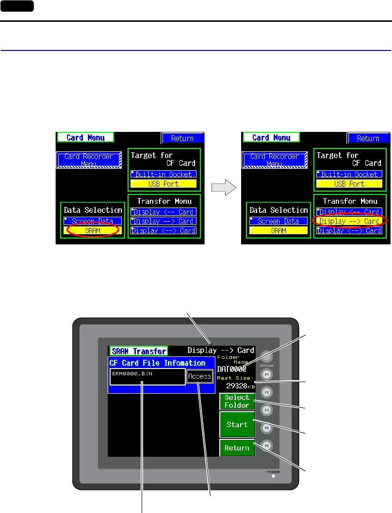
6-24 2. Main Menu Screen
2-3. Saving Backup Copies of SRAM
In this section, the procedure for saving backup copies of the SRAM memory for battery replacement
is explained.
1. Press the [SRAM] switch on the “Card Menu” screen. When the lamp is red, it is selected.
2. Select [Display <-- Card], [Display --> Card] or [Display <--> Card].
3. The “SRAM Transfer” screen is displayed.
•When [Display --> Card] or [Display <--> Card] is selected, the following screen is displayed.
Select the CF card folder having the same name as the access folder for screen data in the
unit. The name is shown on the screen. The transferred file is named as “SRM0000.BIN”.
Data selection Transfer selection
Indicates the name of the
currently selected folder.
Starts transferring data
[Display --> Card].
Flashes during communication with the CF card.
Moves back to the
previous screen.
Shows [Display <--> Card] when [Display <--> Card] is selected.
Indicates the name of the currently selected file.
Used for checking or
renaming folder names.
Indicates the free space
in the CF card.
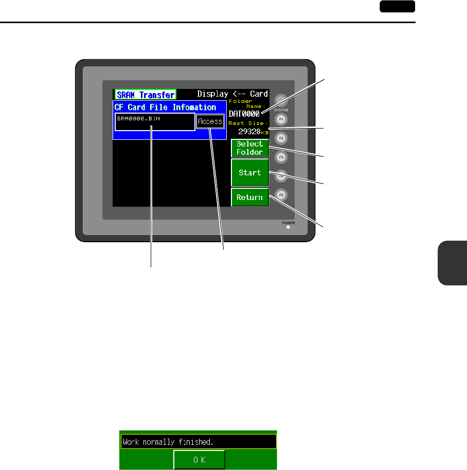
6
2. Main Menu Screen 6-25
POD Operations
•When [Display <-- Card] is selected, the following screen is displayed.
1) To change to another folder, press the [Select Folder] switch.
(The folder name must be “SRM0000.BIN”.)
2) The “Select Folder” screen is displayed as shown on page 6-20.
Select the desired folder (refer to page 6-20), and press the [OK] switch.
3) Moves back to the “SRAM Transfer” screen.
4. Starting Data Transfer
Check the folder name, free space and transfer selection, press the [Start] switch.
Data transfer is started.
5. Ending Data Transfer
When data has been transferred successfully, the following window is displayed.
Press the [OK] switch.
If any other message is displayed, refer to the next page.
6. Pressing the [Return] switch moves back to the “Card Menu” screen.
Indicates the name of the
currently selected folder.
Indicates the free space
in the CF card.
Starts transferring data
[Display <-- Card].
Flashes during communication with the CF card.
Moves back to the
previous screen.
Indicates the name of the currently selected file.
Used for checking or
renaming folder names.
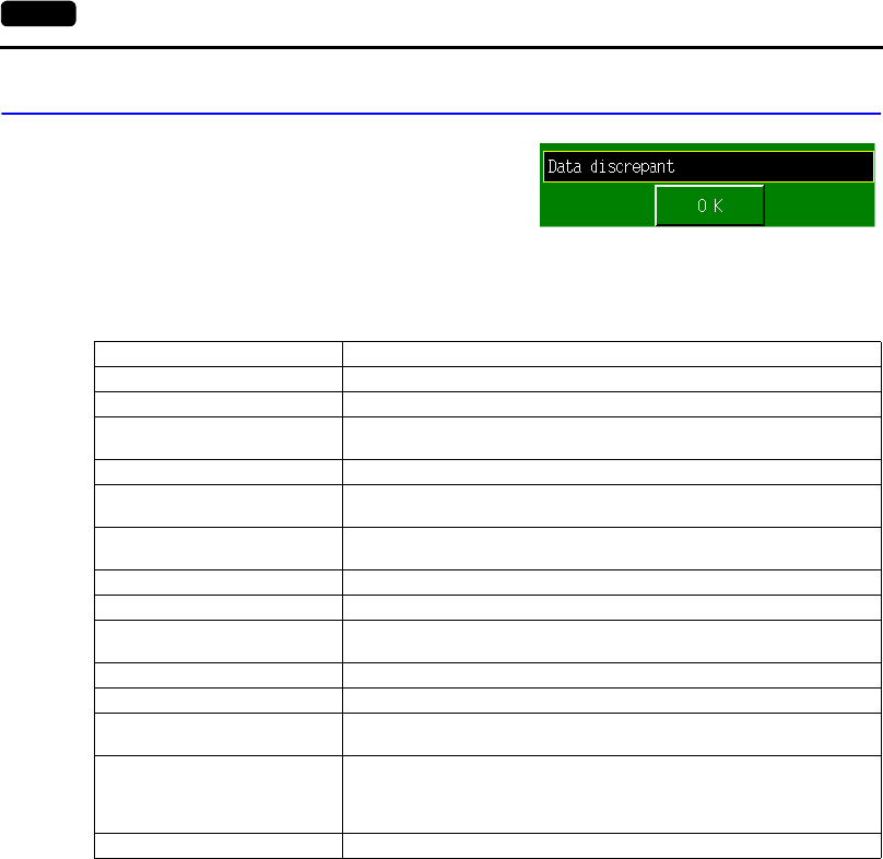
6-26 2. Main Menu Screen
2-4. Messages during Data Transfer
If an error occurs during data transfer, the message
window shown on the right is displayed.
The kinds and the contents of the messages are shown below. The same messages are used for the
memory card and CF card. When using the CF card, the “memory card” in the explanation should
read as the “CF card”.
Message Contents
Work normally finished. The specified operation has been concluded normally.
Card recorder not connecting No card recorder is connected when selecting a modular jack.
UG00P-MR Communication Error A communication error occurred between POD and UG00P-MR when
selecting a modular jack.
Card not setting Memory-Card not setting
Memory-Card Capacity over Cannot write the data into a memory card because the data size in POD is
larger than the capacity of a memory card.
Write Protect: ON Cannot write data into a memory card because the write protect switch in a
memory card is ON.
Writing Error occurred. The error occurred while writing data into a memory card.
Selected data does not exist. The data in the reading target does not exist.
UG type is different. The specified type of the data in POD is different from the type of the memory
card data.
Selected data can not be read. The data in a memory card cannot be read.
Reading Error occurred. The error occurred during writing data into a flash ROM of POD.
Data discrepant There is some discrepancy in data, when comparing data between a memory
card and POD.
Screen data on UG will be broken.
Warning about data destruction in POD that may occur when transferring the
font data larger than the present data from a memory card to POD.
(The [OK] switch continues transferring; the [Cancel] switch stops
transferring.)
Undefined Error occurred. The error occurred due to some cause other than mentioned above.
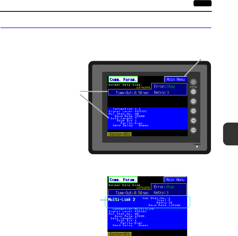
6
2. Main Menu Screen 6-27
POD Operations
3. Communication Parameter Screen
When the [Comm. Para.] switch on the Main Menu screen is pressed, the “Comm. Param.” screen,
shown below, is displayed.
This screen is used to check the UG230 communication parameter settings.
The Main Menu screen is displayed again.
Communication parameter setting
Multi-link 2 or multi-link settings
Displayed when [Multi Link] or [Multi Link 2] is selected
for [Connection] on the [Comm. Parameter] dialog
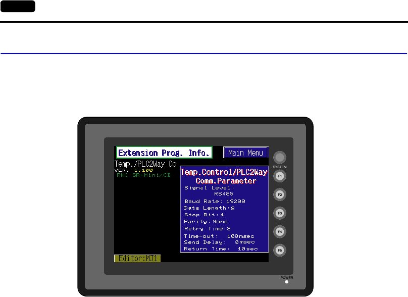
6-28 2. Main Menu Screen
4. Extension Program Information
When the [Extension] switch on the Main Menu screen is pressed, the following “Extension Prog. Info.”
screen appears.
The driver setting and parameter setting for temperature controller/PLC2Way communication, ladder
transfer function, Modbus slave communication, etc. are displayed.
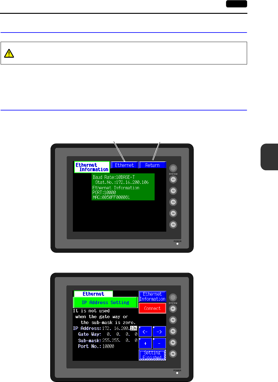
6
2. Main Menu Screen 6-29
POD Operations
5. Ethernet (Optional)
The “Ethernet Information” screen is displayed by pressing the [IP Address (English)] switch on the
initial screen when transferring screen data via Ethernet for the first time, or by pressing the [Ethernet
Information] switch on the Main Menu screen when transferring screen data to a UG230 equipped with
the option unit UG230A-DCL.
5-1. Ethernet Information Screen
This screen is used to check the current IP address, port number, or error.
Pressing the [Ethernet] switch brings up the “Ethernet” screen for IP address setting.
To move back to the previous “Ethernet Information” screen, press the [Ethernet Information] switch.
CAUTION
When performing Ethernet communication on the UG230, the option unit UG230A-DCL
must be installed.
The Main Menu screen is displayed again.
Moves to the “Ethernet” screen for IP Address
Setting. (See “IP Address Setting” (page 6-30))
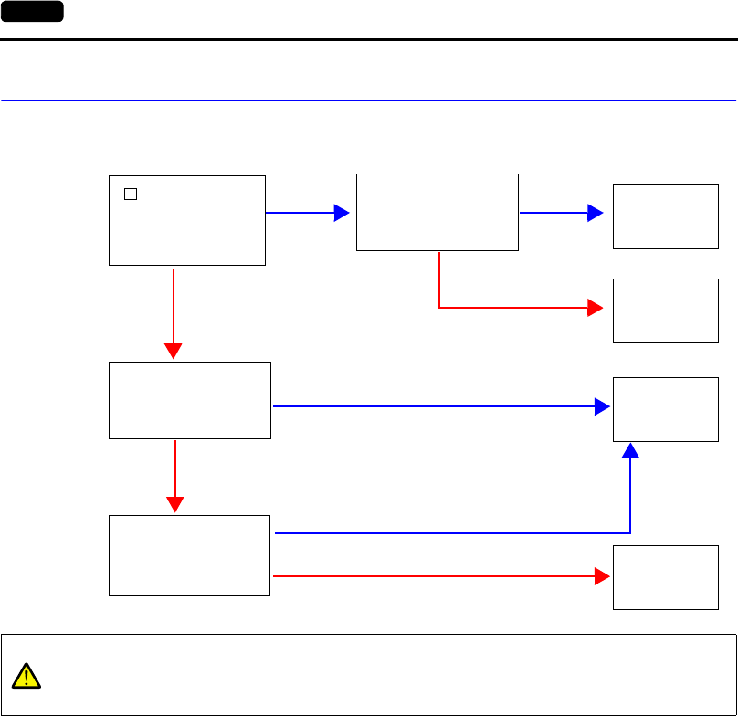
6-30 2. Main Menu Screen
5-2. IP Address Setting
IP address (number for identifying UG230 on the network) setting is required before conducting
communications via Ethernet. The setting procedure varies depending on the screen data conditions.
[ IP Setting] is
checked in the [Unit
Setting] window on
the editor.
Network table on the
editor contains a local
port setting.
No No *
Yes
Yes
No *
Yes
Yes
Network table is set
on the editor.
Network table is set on
the editor. No *
“Setting 1”
(page 6-31)
“Setting 2”
(page 6-32)
“Setting 3”
(page 6-33)
“Setting 4”
(page 6-34)
CAUTION
* When no network table is set on the editor:
• Ethernet macro commands (EREAD, EWRITE, and SEND) disabled
• Communication with PLC via Ethernet disabled
For more information, refer to page 6-32.
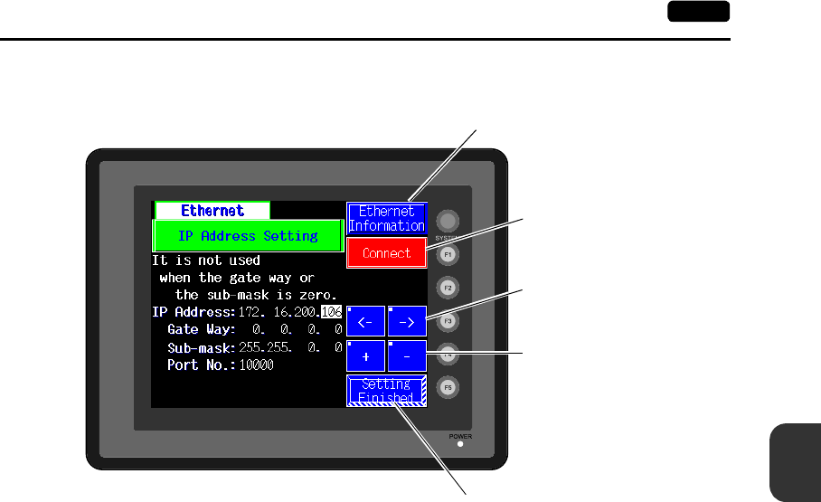
6
2. Main Menu Screen 6-31
POD Operations
Setting 1
Set the IP address on the POD screen.
1. Open the “Ethernet” screen from the “Ethernet Information” screen using the [Ethernet] switch.
2. Set the IP address and other necessary options.
3. Press the [Setting Finished] switch to move back to the Main Menu screen.
Cursor switches
Increment/Decrement switch for
the value in the cursor position
Determines the setting such as IP address,
and moves back to the Main Menu screen.
Used for checking the
10BASE-T interface.
Normal: Connect
Error: Disconnect
The Ethernet screen is displayed.
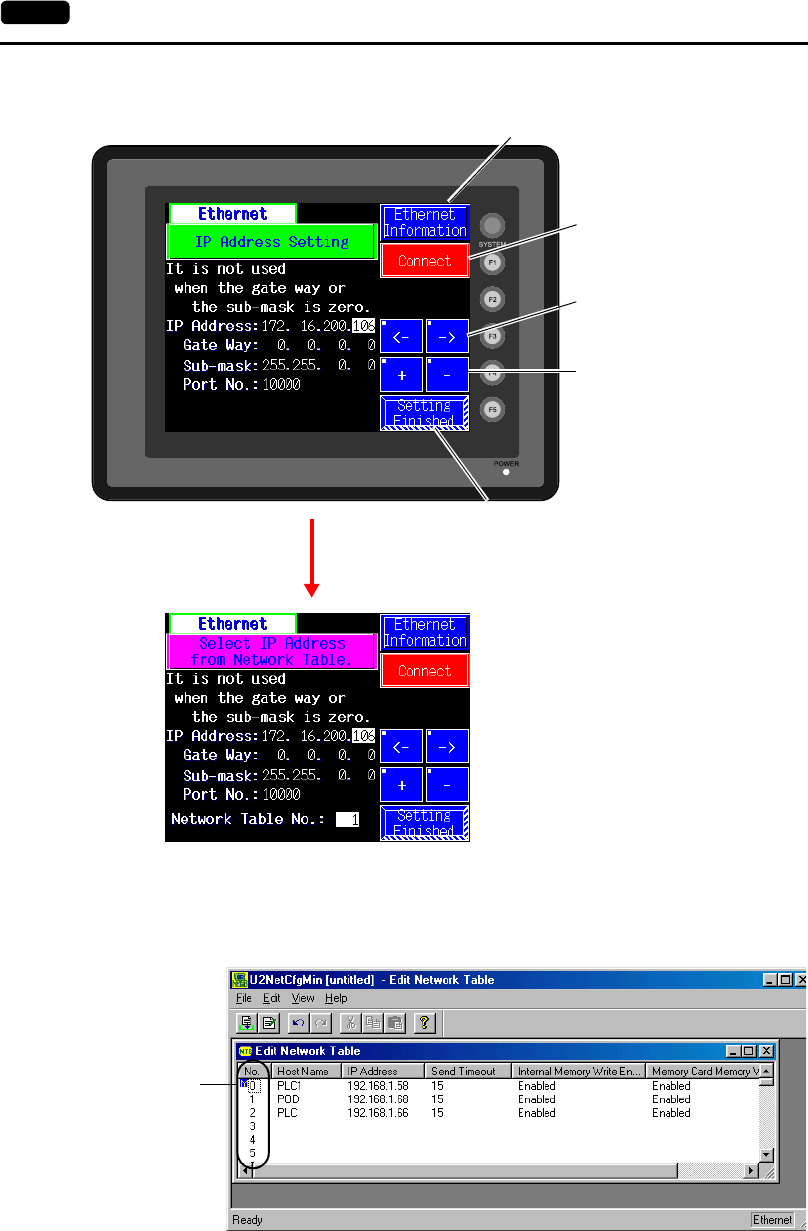
6-32 2. Main Menu Screen
Setting 2
*1 Network Table
Register IP addresses and other information for the UG230, PLCs or computers that should be included for
Ethernet communications on the UG00S-CW editor.
([System Setting] → [Network Table Setting] → [Ethernet] → Edit Network Table)
If you would like to use the IP address of the registered network table, select [IP Address from Network Table].
Cursor switches
Increment/Decrement switch for
the value in the cursor position
Determines the setting such as IP address,
and moves back to the Main Menu screen.
Used for checking the
10BASE-T interface.
Normal: Connect
Error: Disconnect
The Ethernet screen is displayed.
By pressing the [IP Address Setting] switch,
the desired IP address can be selected from
the network table.
The switch changes into [Select IP Address
from Network Table.].*1
Network table
number
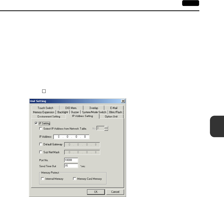
6
2. Main Menu Screen 6-33
POD Operations
Set the IP address on the Main Menu screen.
1. Press the [Ethernet] switch on the Main Menu screen to bring up the Ethernet screen.
2. Change the switch on the screen into [Select IP Address from Network Table.].
3. Select the desired IP address by changing the network table number.
4. Press the [Setting Finished] switch to move back to the Ethernet screen.
Setting 3
Set the IP address on the editor.
1. On the editor, chick [System Setting], [Unit Setting] and [IP Address Setting]. The [IP Address
Setting] dialog is displayed.
2. Check [ IP Setting].
3. Set the following options.
•IP Address
•Default Gateway
•Sub Net Mask
•Port No.
•Send Timeout
•Memory Protect
4. Click the [OK] button and transfer the screen data. The IP address set above can be checked on
the “Ethernet Information” screen to be displayed from the Main Menu screen.
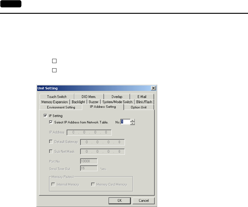
6-34 2. Main Menu Screen
Setting 4
Set the IP address on the editor.
1. On the editor, chick [System Setting], [Unit Setting] and [IP Address Setting]. The [IP Address
Setting] dialog is displayed.
2. Check [ IP Setting].
3. Check [ Select IP Address from Network Table]. Enter the network table number with which
POD’s IP address is registered.
4. Click the [OK] button and transfer the screen data. The IP address set above can be checked on
the “Ethernet Information” screen to be displayed from the Main Menu screen.
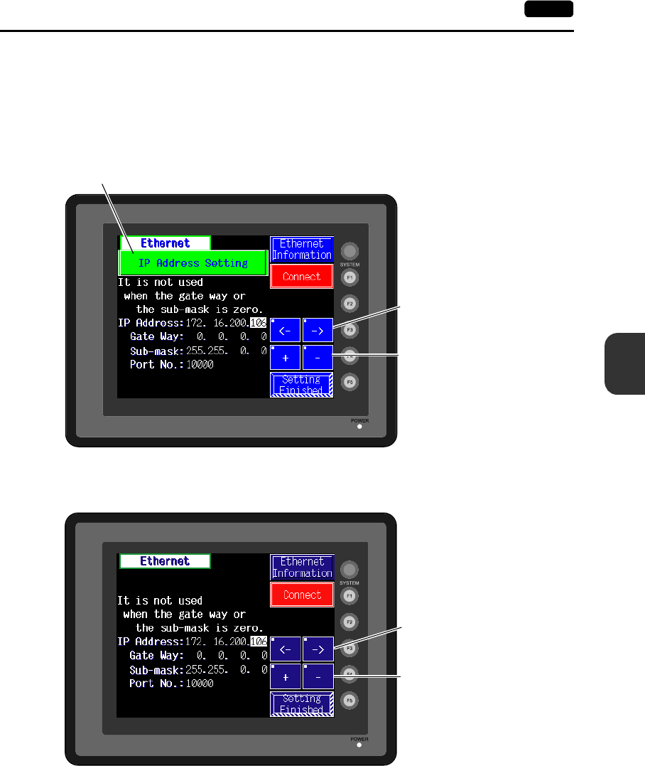
6
2. Main Menu Screen 6-35
POD Operations
Changing the IP Address Temporarily
The IP address can be changed temporarily on the POD screen.
The screen to be used varies depending on the method of IP address setting (page 6-30).
Setting 1/2
Setting 3/4
Cursor switches
Increment/Decrement switch for
the value in the cursor position
Select [IP Address Setting].
Cursor switches
Increment/Decrement switch for
the value in the cursor position
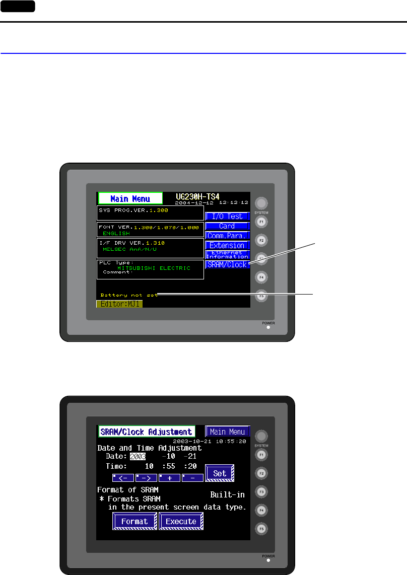
6-36 2. Main Menu Screen
6. SRAM/Clock
•To use the built-in clock of the UG230, it is necessary to select [SRAM/Clock Setting] from the
[System Setting] menu and make the SRAM/clock setting.
For the setting procedure, refer to the User’s Manual <Function> (FEH376).
•Be sure to set the battery when using the built-in clock of the UG230. Without battery, the contents
in the SRAM or clock data will not be retained.
When the battery is not connected, the message “Battery not set” is displayed and the
[SRAM/Clock] switch flashes on the Main Menu screen. Connect the battery immediately.
When the battery is to be replaced, the message “Brownout Battery” is displayed.
•When the [SRAM/Clock] switch on the Main Menu screen is pressed, the following “SRAM/Clock
Adjustment” screen appears.
This screen is used for adjusting the built-in calendar and for initializing the SRAM area.
[SRAM/Clock] switch
Indicates the message,
such as “Battery not set”
or “Brownout Battery.”

6
2. Main Menu Screen 6-37
POD Operations
Date and Time Setting
1. Move the cursor using the [←] / [→] switch, and change the value by pressing the [+] / [−] switch.
2. When the desired date and time are set, press the [Set] switch to determine the setting.
3. The calendar data is updated as set.
Initializing SRAM
When the SRAM memory or cassette is initialized, the data contained is cleared. Double-check before
initializing the SRAM memory or cassette.
1. Press the [Format] switch and the [Execute] switch.
2. The SRAM area is initialized in the current screen data format. When initialization has been
completed, the message “∗∗Format Completed∗∗” is displayed.
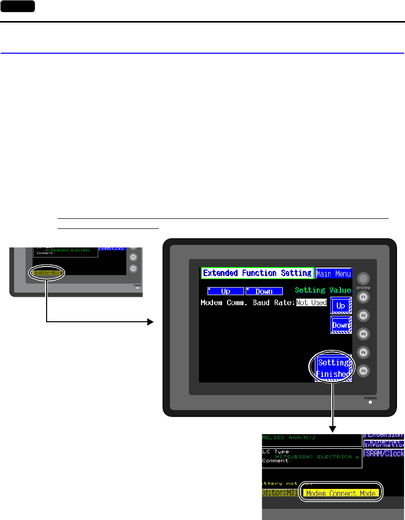
6-38 2. Main Menu Screen
7. Extended Function Setting
When the [Editor: MJ1] switch on the Main Menu screen is pressed, the following “Extended Function
Setting” screen appears.
Set the baud rate to be used when transferring screen data between the UG230 and a modem.
1. Select the desired baud rate using the [↑] / [↓] switch, and press the [Setting Finished] switch.
(Setting range: 4800, 9600, 19200, 38400, 57600, 115200)
* The function switches and switches on the Main Menu screen are not valid for 15 seconds
after the [Setting Finished] switch is pressed.
* When the [Setting Finished] switch is pressed, an AT command is automatically sent to the
modem and the baud rate used between the UG230 and the modem is set.
2. The Main Menu screen is displayed automatically. [Modem Connect Mode] automatically appears
under [Editor: MJ1].
3. To transfer screen data without a modem, select “Not used” for [Modem Comm. Baud Rate].
For screen data transfer while a computer is connected with UG00C-T, specify [Not Used] for
[Modem Comm. Baud Rate].
Pressing the [Editor: MJ1] switch
brings up the “Extended
Function Setting” screen.
Pressing the [Setting Finished] switch
moves back to the Main Menu screen.

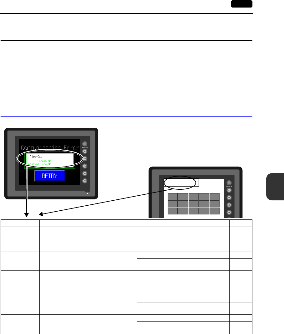
7
1. Error Messages 7-1
Error Correction
1. Error Messages
There are five kinds of error messages displayed on the UG30 series:
1. Communication error
2. Check
3. Warning
4. SYSTEM ERROR
5. Touch switch is active
1. Communication Error
* If the above error messages are displayed on the POD without establishing communication
between POD and PLC, test the solution of remark “1.”
If the error occurs suddenly in communication, test the solution of remark “2.”
MENU
Communication Error
Time-Out
* When you go to [Comm. Parameter],
bring up the [Detail] tab window and set
[Continue] for [Comm. Error Handling],
a screen like the one shown below is
displayed.
Error Message Contents Solution Remarks
Timeout Although a request to send is given to the PLC,
no answer is returned within the specified time.
1. Check the communication parameters.
2. Check the cables and wiring. 1
3. Data may be disrupted because of noise.
Fix noise. 2
Parity An error occurred in parity check.
1. Check the cables and wiring. 1
2. Data may be disrupted because of noise.
Fix noise. 2
Framing Although the stop bit must be [1], it is detected
as [0].
1. Check the communication parameters.
2. Check the cables and wiring. 1
3. Data may be disrupted because of noise.
Fix noise. 2
Overrun
After one character is received, the next
character is received before internal processing
is completed.
1. Check the communication parameters. 1
2. Data may be disrupted because of noise.
Fix noise. 2
Check code error The check code in the PLC response was not
correct.
1. Check the communication parameters. 1
2. Data may be disrupted because of noise.
Fix noise. 2
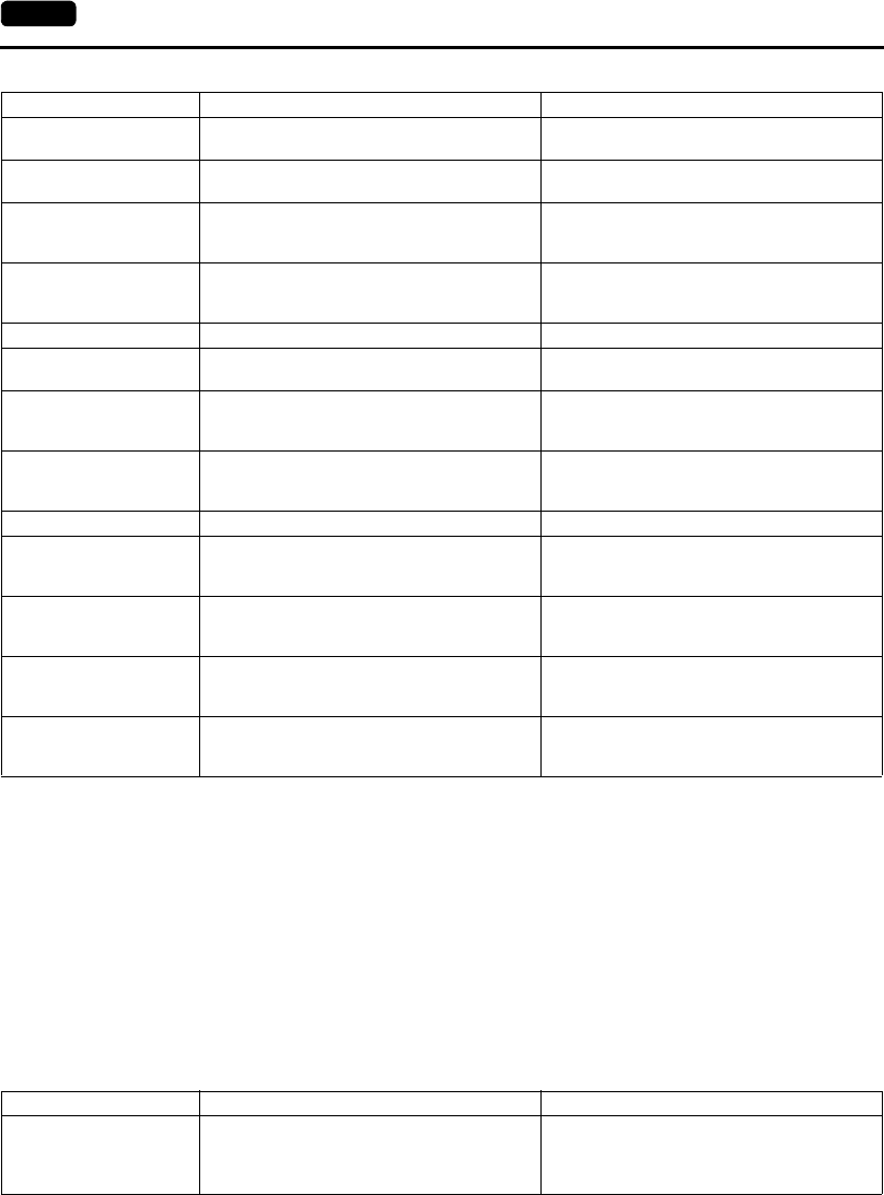
7-2 1. Error Messages
Solution
1. Confirm link unit settings. (After making settings, cut power to the PLC.)
2. Go to the editor and confirm the settings in the [Comm. Parameter] dialog in the [System Setting]
menu.
3. If errors only occur from time to time, it is possible that there is a noise-based communication error.
* If you still cannot solve the error even after following the suggestions above, contact your local
distributor.
Error Messages for Network Communication
•Ethernet
Error Message Contents Solution
Error code received The PLC sent an error code (NAK). Examine the PLC error code and solve the
problem.
Break The PLC’s SD (TXD) remains at the low level. Examine the connection between the PLC’s SD
(TXD) and the UG series RD (RXD).
Invalid memory
(applicable to Mitsubishi
CPU)
You specified an address that exceeds the
memory range of the PLC that you are linked to.
Check the type and range of memory that you
set.
Invalid CPU model
(applicable to Mitsubishi
CPU)
The PLC currently being supported does not
have a corresponding CPU.
Confirm whether or not the CPU that you are
using can be used with the UG series.
Format The code of the received data is invalid. Check 1, 2, 3 described below.
Compare
(applicable to HIDIC S10)
Transmission data and received data are
different. Check 1, 2, 3 described below.
NAK
(applicable to
Allen-Bradley PLC)
A NAK code is received. Check 1, 2, 3 described below.
TNS discrepant
(applicable to
Allen-Bradley PLC)
Transmitted TNS data and received TNS data
are not in agreement. Check 1, 2, 3 described below.
Communication Error An unclear communication error is detected. Check 1, 2, 3 described below.
Count error
(applicable to Mitsubishi
CPU and Q link unit)
The expected data amount is different from the
count value. Check 1, 2, 3 described below.
Command error
(applicable to Mitsubishi
CPU and Q link unit)
The response code differs from the expected
code. Check 1, 2, 3 described below.
Invalid cassette
(applicable to Mitsubishi
ACPU)
This cassette is not included in the memory
cassettes currently being supported. Contact your local distributor.
Password error
(applicable to Mitsubishi
QCPU)
The password is incorrect. Contact your local distributor.
Error Message Contents Solution
Ethernet Error: XXXX
The Ethernet status is saved at system memory
address $s518 and a code other than “0”
(normal) is received.
XXXX: Error No.
For the contents and solution to each error
number, refer to Appendix 5 of the User's
Manual <Function> (FEH376) separately
provided.
7
1. Error Messages 7-3
Error Correction
2. Check
3. Warning
An error may be displayed on the Main Menu screen during data transfer.
This is a warning message.
For the warning details and solutions, refer to the User's Manual <Function> (FEH376) and correct
screen data.
Error Message Contents Solution
Screen No. Error There is no setting for the received screen.
At the start of communications, the UG30 series
regards the value in the read area “n + 2” as the
screen number.
Check that the value in the read area “n + 2” is
an existing screen number on the PLC.
Data has some error.
Error : XX (XX : XXX) There is an error in the created screen data.
“Error : XX (XX : XXX)” indicates the edited
screen and the contents of the error.
For the error details and solutions, refer to the
User's Manual <Function> (FEH376) and
correct screen data.
Communication Error
Check I/F driver
Error Message Contents Solution
Communication Error
Check I/F driver
Although a request to send is given to the
computer, no answer is returned within the
specified time.
The I/F driver for simulator is transferred.
If you do not use the simulator, uncheck [Use
Simulator] before transferring data.
Warning message
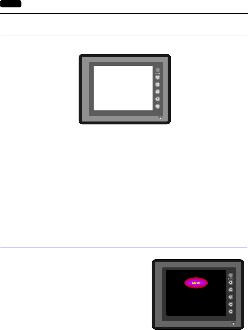
7-4 1. Error Messages
4. SYSTEM ERROR
When a system error is detected, the following error screen is displayed.
ERROR: XX
1: Watch dog timer error
11: Switch table error
30: Request for displaying full error
31: Memory allocation system error
32: General exceptions/MMU address system error
33: RTOS system error
34: Memory error
35: Inaccurate memory error
The source of the error could be one of the following three problems.
1) Program crash due to noise
2) Hardware problem
3) Bad program
Solve relevant problems by following the directions in “Troubleshooting” (page 7-5).
If the problem persists, contact your local distributor.
5. Touch Switch is Active
If the power is turned off while a touch switch is
activated, the following error screen is displayed.
Remove your finger from the screen.
If the error screen remains displayed, contact your
local distributor.
SYSTEM ERROR : 32
TEA : XXXXXXXX
SSR : XXXXXXXX
R0 : XXXXXXXX
R2 : XXXXXXXX
R4 : XXXXXXXX
R6 : XXXXXXXX
R8 : XXXXXXXX
R10 : XXXXXXXX
R12 : XXXXXXXX
R14 : XXXXXXXX
EXPEVT : XXXXXXXX
SPC : XXXXXXXX
R1 : XXXXXXXX
R3 : XXXXXXXX
R5 : XXXXXXXX
R7 : XXXXXXXX
R9 : XXXXXXXX
R11 : XXXXXXXX
R13 : XXXXXXXX
R15 : XXXXXXXX
Touch switch is active.
Keep hand off the screen.
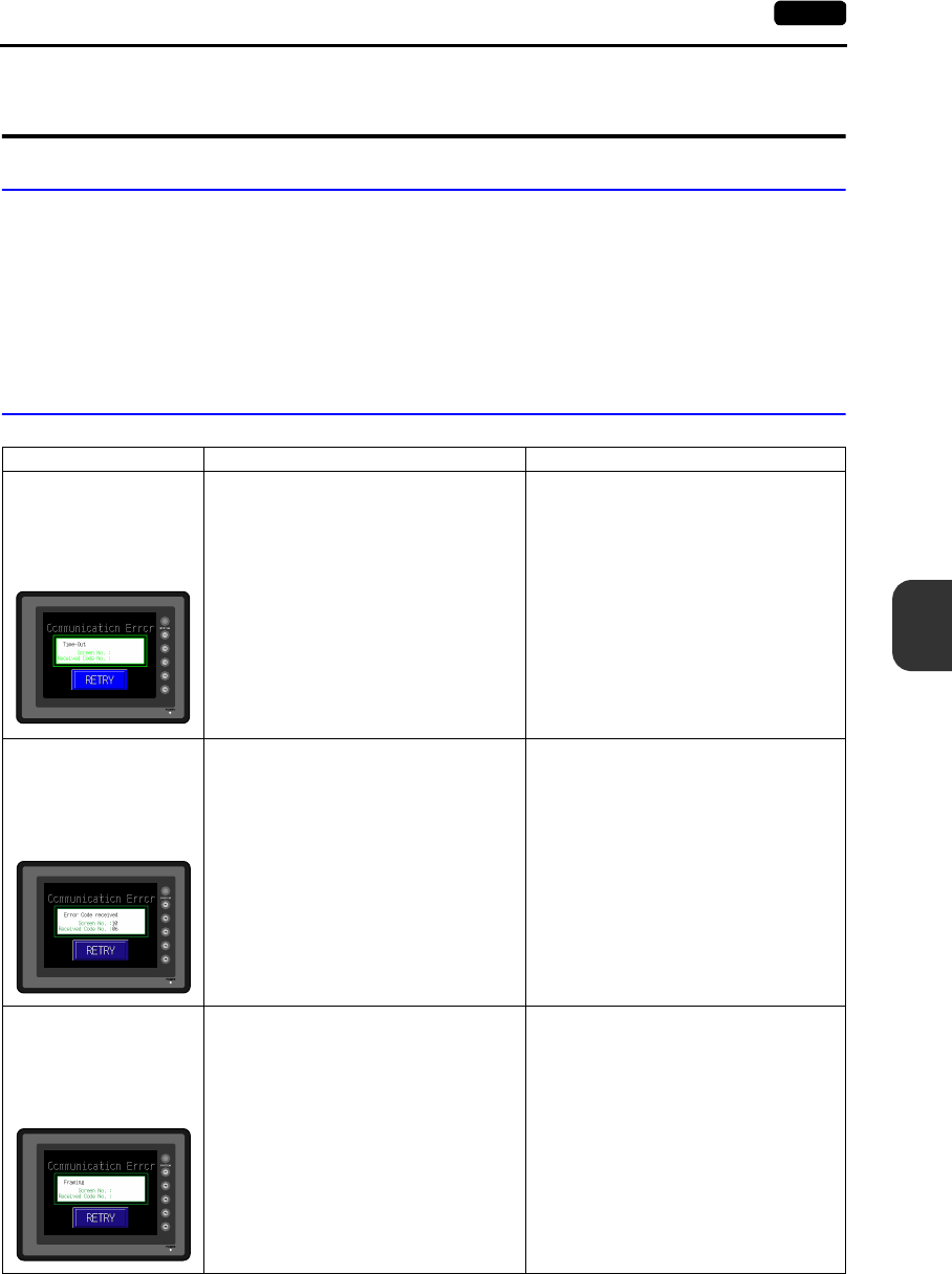
7
2. Troubleshooting 7-5
Error Correction
2. Troubleshooting
In the Event of an Error
Perform the steps below:
1. If the current error matches a symptom in the following table, correct it by following the instructions
provided.
2. If the error does not match the symptoms in the table, contact your local distributor.
Please provide the distributor with the information on the POD model, serial number, symptom of
the error, error message (if shown), etc.
Probable Symptoms
Symptom Cause Solution
POD is connected to the
PLC; however,
communication fails.
“Communication Error:
Time-Out” appears on the
screen.
Probable causes are: Solutions are:
1) Cables are not connected correctly or any
cable is disconnected.
1) Check the cable connection.
2) PLC parameter settings are not correct or
disagree with the POD settings.
2) Recheck the PLC parameter settings.
3) The POD is faulty. 3) Perform a self-loop test on the “I/O Test”
screen (page 6-7).
If the test is not successful, please return
the POD to your local distributor
immediately.
Communications have been
successful. However,
opening a certain page
always causes a
“Communication Error: Error
code received” error.
The error code denotes a PLC error (NAK).
1) When the error code appears only on a
certain screen, a memory address that
does not exist on the PLC may be set on
the POD screen.
1) Check if any address outside the allowable
range for PLC memory is set on the screen.
2) When the error code appears at power-on,
a memory address that does not exist on
the PLC may be set for communication
parameters, buffering area, initial macro,
etc.
2) Check if any address outside the allowable
range for PLC memory is set for
communication parameters, buffering area,
initial macro, etc.
Communications have been
successful. However,
“Communication Error:
Parity” or “Communication
Error: Framing” suddenly
occurs.
Noise may cause the error. Check if appropriate measures are taken
against noise.
Example:
Check if communication and power cables are
bundled together.
Try to attach a ferrite core to the
communication cable.
Try to attach a noise filter to the power supply,
etc.
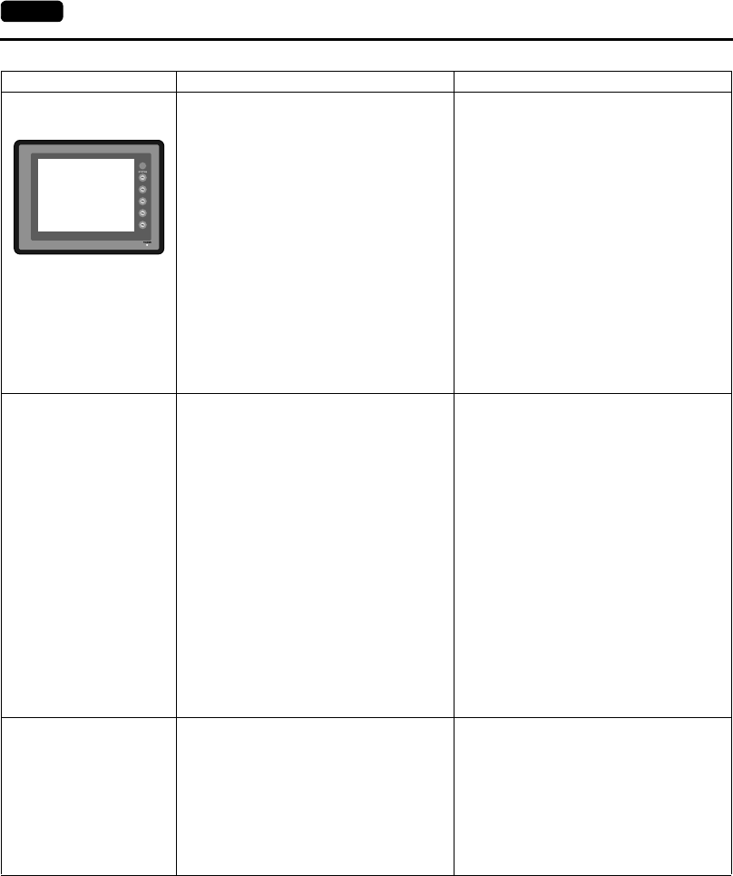
7-6 2. Troubleshooting
“SYSTEM ERROR: xx”
occurs.
The following causes are probable, depending
on the symptoms.
1) Turning the power off and back on corrects
the error.
↓
Communication failed because of improper
timing.
1) If communication is stable after turning the
power on again, continue and observe
operation.
2) Turning the power off and back on does not
correct the error.
↓
A certain condition always causes the error.
Or the POD is faulty.
2) Make a note of the information on error
number, etc. displayed on the screen and
contact your local distributor.
3) A CF card is inserted.
↓
The CF card (front and back) may be
reversed.
If none of the above matches your error,
contact your local distributor.
3) Check that the inserted CF card faces the
correct side.
Switches do not work. 1) Switches do not work in the RUN mode. A
beep sounds.
↓
Is the switch interlock enabled?
1) Check the settings of switch functions, etc.
on the editor.
2) Switch activation position is wrong.
On the “I/O Test” screen displayed from the
Main Menu screen, press the [Switch
Check] switch. On the touch switch test
screen, a position different from the
pressed position is activated.
↓
The switch activation position may be
misaligned.
2) Perform a touch switch adjustment (page
6-14).
3) Switches do not work even in the STOP
mode.
On the “I/O Test” screen displayed from the
Main Menu screen, press the [Switch
Check] switch. When the touch switch test
screen is pressed, nowhere is activated.
↓
POD switches may be faulty.
3) Return the POD to your local distributor.
The screen becomes dark or
black.
1) Touching the screen restores it to the
previous illuminated state.
↓
The backlight operates automatically as
preset.
1) The time for turning off the backlight can be
changed on the editor.
2) Touching the screen does not restore it.
However, the POWER lamp is lit.
↓
The backlight may be at the end of its life.
Or the POD may be faulty.
2) Return the POD to your local distributor.
Symptom Cause Solution
SYSTEM ERROR : XX
TEA : XXXXXXXX
SSR : XXXXXXXX
R0 : XXXXXXXX
R2 : XXXXXXXX
R4 : XXXXXXXX
R6 : XXXXXXXX
R8 : XXXXXXXX
R10 : XXXXXXXX
R12 : XXXXXXXX
R14 : XXXXXXXX
EXPEVT : XXXXXXXX
SPC : XXXXXXXX
R1 : XXXXXXXX
R3 : XXXXXXXX
R5 : XXXXXXXX
R7 : XXXXXXXX
R9 : XXXXXXXX
R11 : XXXXXXXX
R13 : XXXXXXXX
R15 : XXXXXXXX
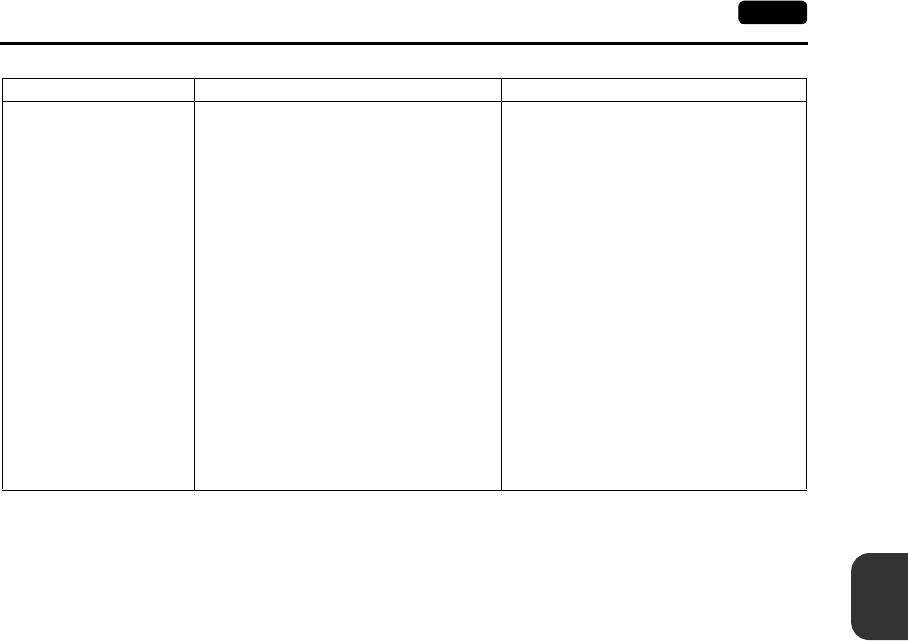
7
2. Troubleshooting 7-7
Error Correction
Screen data cannot be
transferred.
1) Screen data transfer has never succeeded.
↓
There may be some errors in the settings
on the computer.
1) In the [Transfer] dialog box on the editor,
decrease the baud rate by one level. Also
check that the correct COM port is
selected.
2) Screen data transfer was possible, but is
disabled now.
↓
The POD may be faulty. Or, there may be
some errors in settings.
2) Check if the modem connection mode is
selected (“Modem Connect Mode”
displayed at the bottom of the Main Menu
screen denotes the mode).
Also perform an RS-232C self-loop test
(page 6-7).
3) Only serial transfer is successful.
↓
There may be some errors in the Ethernet
or USB settings.
3) Transfer via Ethernet
Check that the IP addresses set on the
editor and the POD are the same.
Also check if any error due to Ethernet
connection occurs on the POD.
Transfer via USB
Is the USB driver recognized? Has the
driver been installed successfully (page
2-21)?
If the problem persists, contact your local
distributor.
Symptom Cause Solution

7-8 2. Troubleshooting
Please use this page freely.

8
1. Inspection and Maintenance 8-1
Inspection and Maintenance
1. Inspection and Maintenance
Daily Inspection
•Check that the screws on the POD are tightened firmly.
•Check that the connectors and terminal screws used for connection with other devices are
tightened firmly.
•If the display surface or frame is dirty, wipe it with a soft cloth soaked in alcohol (commercially
available).
•Conduct periodical inspection once or twice a year. The number of inspections may be increased
as necessary if facilities are relocated or modified, or the environment is hot, humid, or dusty.
Periodical Inspection
Inspect the following points periodically.
•Are the ambient temperature and humidity appropriate?
0 to +50°C, 85%RH or less
•Are the environmental conditions appropriate?
•Does the atmosphere contain no corrosive gas?
•Is the source voltage in the allowable range?
With AC power supply: 100 - 240 VAC
With DC power supply: 24 VDC ± 10%
•Are the POD mounting screws tightened firmly?
•Are the connectors and terminal screws used for connection with other devices tightened firmly?
•Is the lithium primary battery within the expiry date?
DANGER Be sure to turn off the power before conducting inspection or maintenance. Failure to
do so could cause an electric shock or damage to the unit.

8-2 2. Warranty Policy
2. Warranty Policy
Inquiries about Failure
Please direct inquiries about failure or repair to your local distributor.
Your information on the POD model, serial number, symptom of the failure, error message (if shown),
etc. will be appreciated.
Warranty Period
The product is under warranty for one year after the date of purchase or delivery to the specified place.
On the assumption that the maximum stock period of the product after manufacture is 6 months, the
warranty period is limited to 18 months (checked by the serial number) after manufacture. When a
warranty period is specified in the contract, however, the period in the contract takes precedence.
Free-of-charge Repair
If the product fails before the expiry of the warranty, it will be repaired free of charge.
However, repair of any failure resulting from the causes below will be chargeable even within the
warranty period.
•Breakage of or damage to the appearance (case or surface sheet), touch switches, LCD, or other
components due to dropping, impact, or mishandling
•LCD or backlight at the end of life
•Fusion of a printed circuit board pattern associated with connection to external devices, or fusion
of a pattern in the terminal block or connector section of a printed circuit board caused by
short-circuiting of external load circuit
•Overvoltage or different voltage applied due to wiring mistake (power supply terminal, external
communication terminal, or other terminal blocks)
•Failure caused by lightning surge
•Failure due to the entry of conductive substances, water, solvent, particles, etc. under
inappropriate environmental conditions
•Failure due to inappropriate environmental conditions (e.g. corrosive gas or high humidity)
•Failure due to vibration or impact exceeding the specified level
•Disassembly and modification by the customer or failure obviously resulting from improper
handling by the customer
Chargeable Repair
Any failure that occurs after the expiry of the warranty or does not satisfy the requirements for the
free-of-charge repair will be repaired on an chargeable basis.

Gate City Ohsaki, East Tower,
11-2, Osaki 1-chome, Shinagawa-ku, Tokyo 141-0032, Japan
Phone: +81-3-5435-7135 ~ 8
Fax: +81-3-5435-7456 ~ 9
URL: http : // www.fujielectric.co.jp / fcs / eng
Information in this manual is subject to change without notice. 2004-2(PDF)
