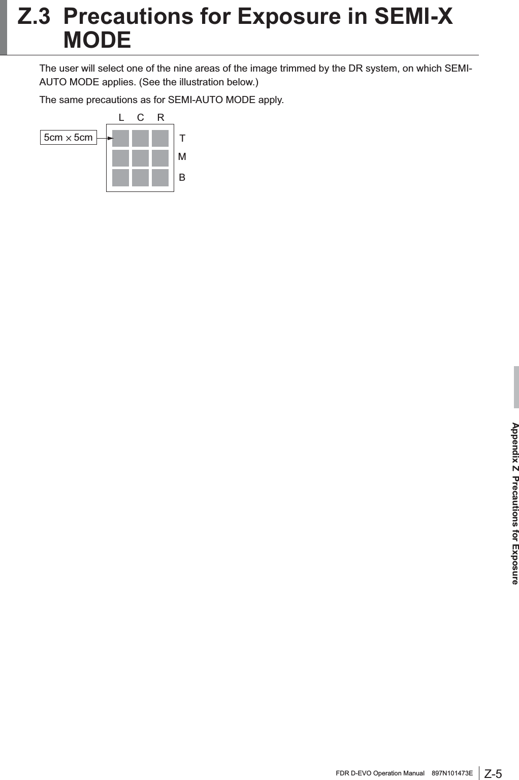
Fuji Film 01000001 D-EVO G35i User Manual 897N101473E Z72N2000E 101026
Fuji Film Corporation D-EVO G35i 897N101473E Z72N2000E 101026
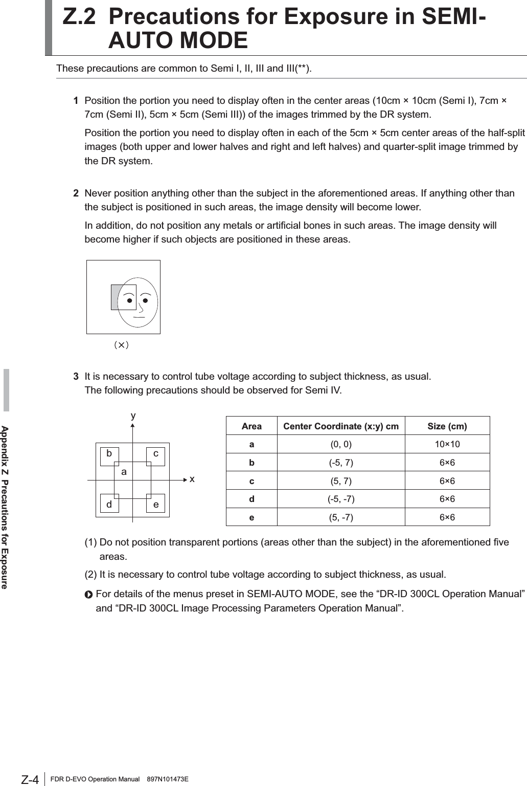
UserManual.wiki
>
Fuji Film
>
01000001 User Manual
Users Manual
Navigation menu
Upload a User Manual
Namespaces
Wiki Guide
HTML
PDF
Info
Views
User Manual
Discussion / Help
Navigation
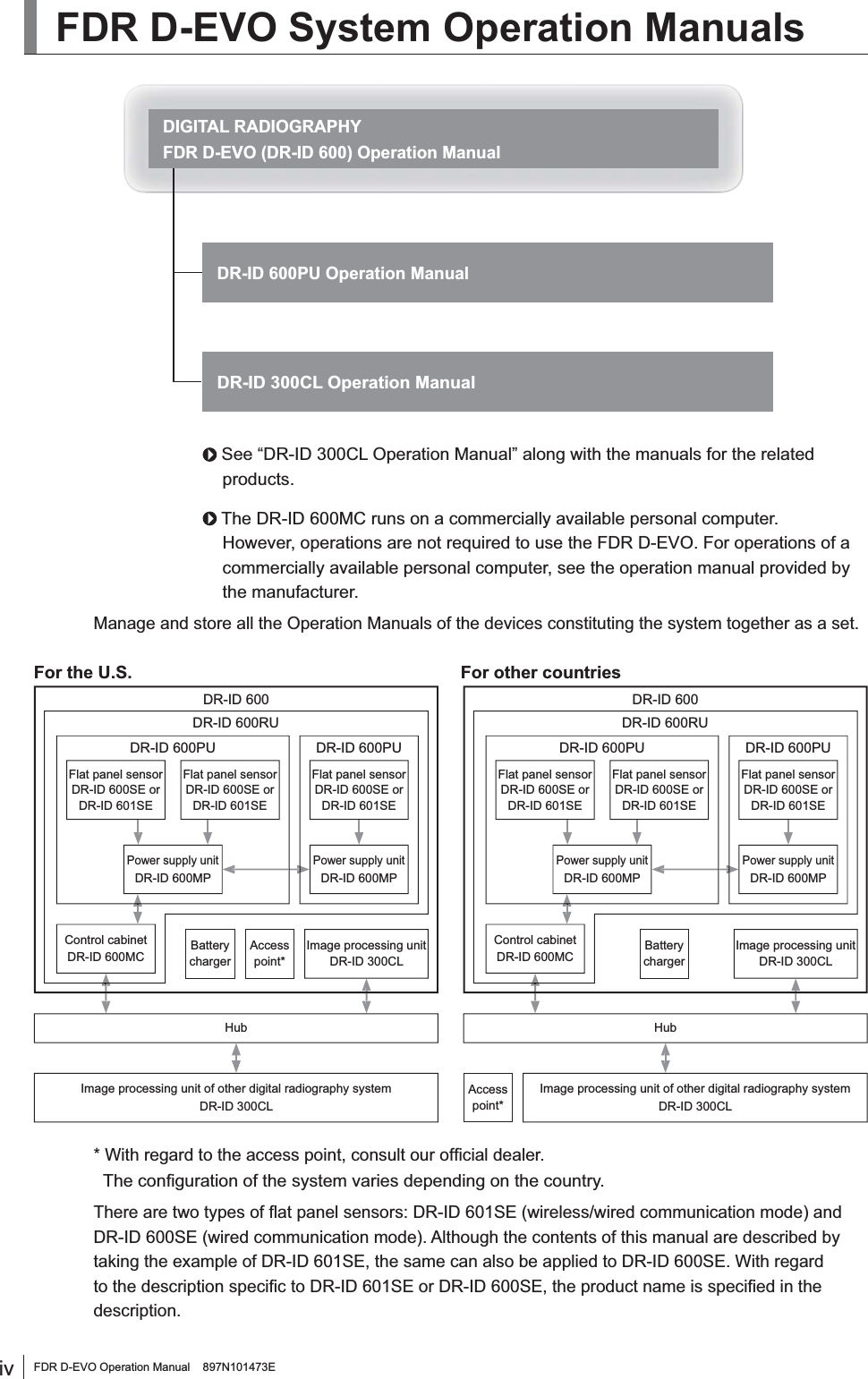
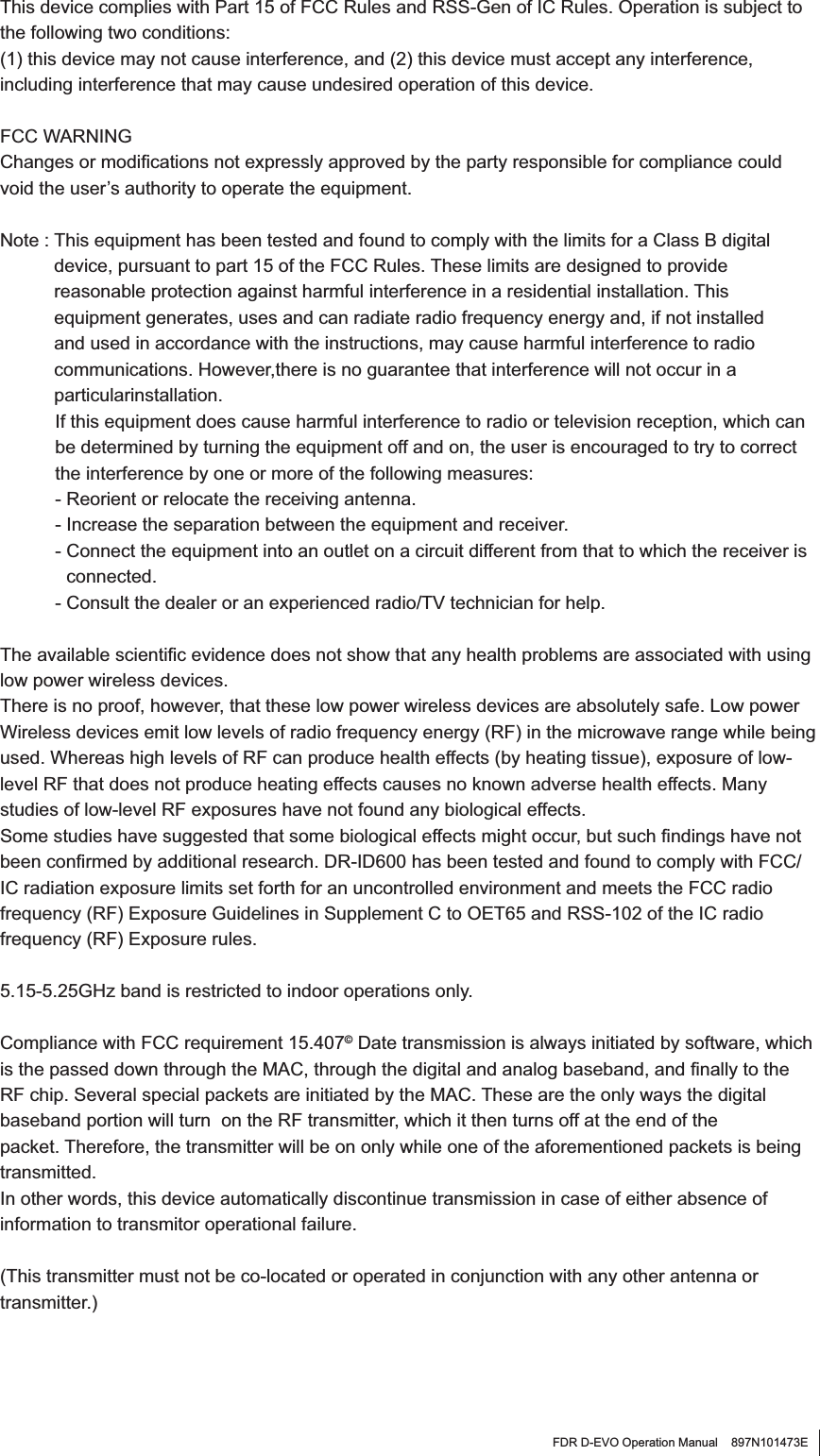
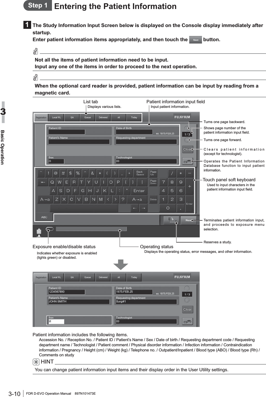
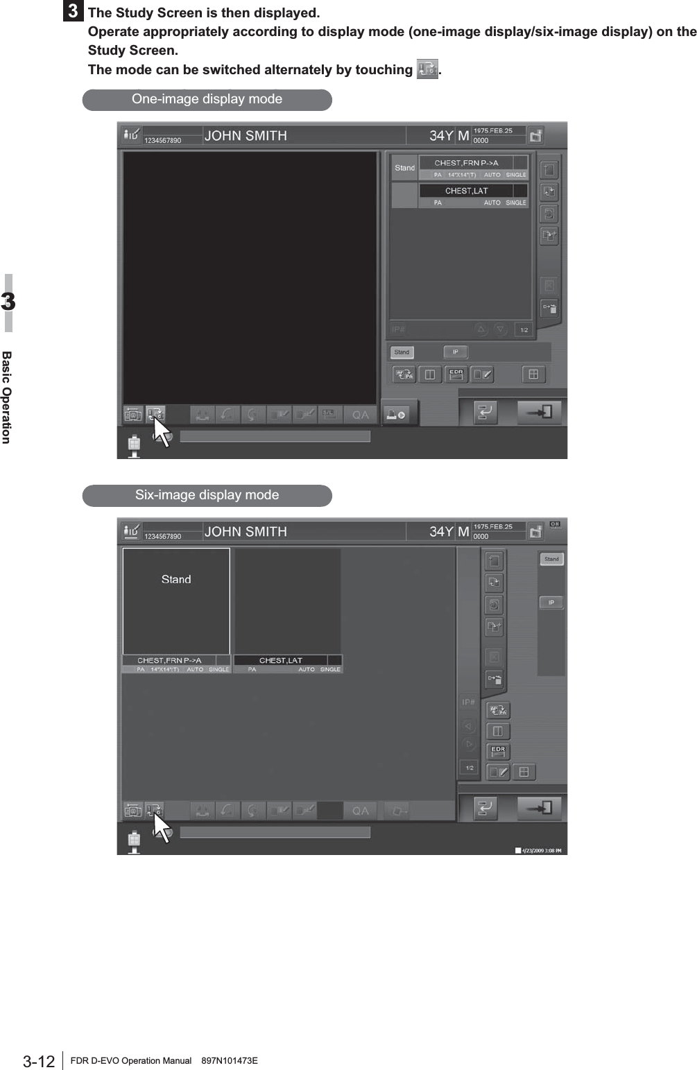
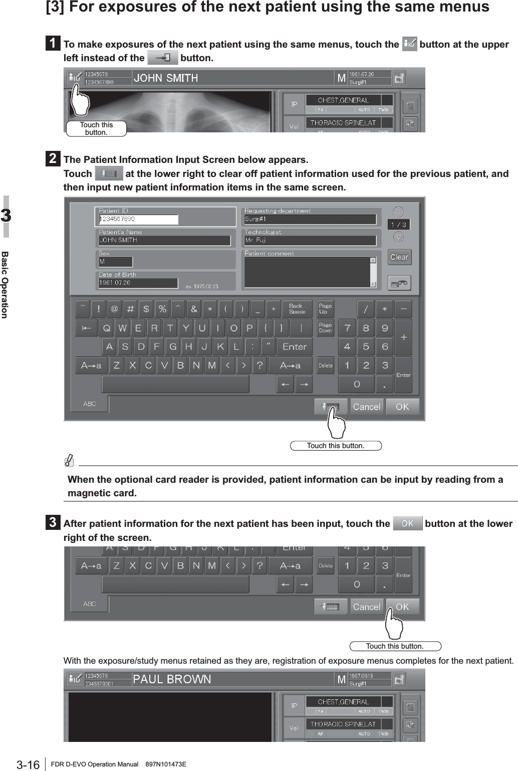
![vi FDR D-EVO Operation Manual 897N101473EHow to Read This Manual%DVLFSDJHOD\RXW3OHDVHKDYHDJRRGJUDVSRIWKHEDVLFSDJHFRQ¿JXUDWLRQRIWKLV2SHUDWLRQ0DQXDODVLOOXVWUDWHGEHORZIRU\RXWRXVHLWPRUHHI¿FLHQWO\3-7FDR D-EVO Operation Manual 897N101473EBasic Operation33.2 Starting Up and Shutting Down the SystemThis section explains how to start up and shut down the system. To start up the system, operations are required on the FDR D-EVO main unit and on the Console. To shut down the entire system, operations are required only on the Console.3.2.1 Starting Up the System1Press the ON side of the main switch of the power supply unit, if its power status LED is not lit.2After FRQ¿UPLQJ the IROORZLQJ LWHPV SUHVV the power VZLWFK for the &RQVROH to VWDUW theinitialization process.$OOFDEOHVVKRXOGEHFRQQHFWHGSURSHUO\1RPHGLDVKRXOGEHLQVHUWHGLQWRWKH)''7KHFRQWUROFDELQHWVWDUWVXSDXWRPDWLFDOO\CAUTIONSIf the power status LED of the power supply unit does not come on after turning on the &RQVROH turn on the control FDELQHW3Turn on the radiographic examination stand.4After displaying the start-up progression status, software version, and initialization progression VWDWXV the DFWLYDWLRQ FRPSOHWLRQ VFUHHQ EHORZ ZLOO EH GLVSOD\HG on the &RQVROH$FWLYDWLRQFRPSOHWLRQVFUHHQRIWKH&RQVROHCAUTIONSAn error occurs if the system is started up immediately after shutdown.To restart the system, make sure that the power status LED of the power supply unit is off, and then SUHVV the power VZLWFK for the &RQVROH3DJHQXPEHUDisplayed in conjunction with the chapter number.Section titleShows the title of an operation procedure described in the section.LeadDescribes information we wish you to know in advance of your operating the system or information that may help you to operate it. Displayed screenA screen that appears during operation.Operation procedureDescribes an operation procedure according to sequential numbers.IndexA caption that facilitates you to open a desired [Chapter] quickly.](https://usermanual.wiki/Fuji-Film/01000001/User-Guide-1413644-Page-6.png)

![ixFDR D-EVO Operation Manual 897N101473E3.2 Starting Up and Shutting Down the System ............................................................ 3-73.2.1 Starting Up the System ............................................................................................3-73.2.2 Shutting Down the System ......................................................................................3-83.3 Routine Operations ................................................................................................. 3-9Step 1 Entering the Patient Information ............................................................................3-10Step 2 Selecting the Anatomical Region and Exposure/Study Menu................................ 3-11Step 3 X-ray Exposure ......................................................................................................3-13[1] Positioning the patient ......................................................................................3-13[2] X-ray exposure/Image displaying .....................................................................3-14[3] For exposures of the next patient using the same menus ................................3-16Chapter 4 TroubleshootinJ4.1 When a Message Appears on the Console ............................................................. 4-1[1] If a warning dialog box appears .........................................................................4-1[2] If a communication error occurs between the Console and the connected DR system ................................................................................................................4-1[3] If an error occurs on the Console .......................................................................4-2[4] If an error occurs on an output destination device ..............................................4-24.2 How to Cope with an Error... ................................................................................... 4-3[1] When the system hangs up... .............................................................................4-3[2] When the Console is turned off due to an electrical outage ...............................4-4[3] If a hard disk of the Console is damaged ...........................................................4-4[4] If a white image is displayed after an exposure ..................................................4-4[5] Precautions for operating the system when “Initializing” or “Changing FPD” is displayed in the Console’s operating status display at the time of replacing the ÀDWSDQHOVHQVRU .................................................................................................4-4>@,IZLUHOHVVFRPPXQLFDWLRQZLWKWKHÀDWSDQHOVHQVRU'5,'6(LVQRWpossible ...............................................................................................................4-4>@,IZLUHOHVVFRPPXQLFDWLRQPRGHLVGLVDEOHGZKHQXVLQJWKHÀDWSDQHOVHQVRU(DR-ID 601SE) ....................................................................................................4-4Chapter 5 Daily Inspection and Maintenance5.1 Daily User Inspection and Maintenance .................................................................. 5-15.1.1 Daily Inspection (DR-ID 600) ...................................................................................5-15.1.2 Periodical Inspection ................................................................................................5-25.1.3 Effective Period of Use ............................................................................................5-2$SSHQGL[$6SHFL¿FDWLRQs$ 6SHFL¿FDWLRQV ..........................................................................................................A-1A.1.1 Processing Capacity (DR-ID 600) ........................................................................... A-1A.1.2 Image Output (DR-ID 600) ...................................................................................... A-1A.1.3 Reduced Equivalent (DR-ID 600) ........................................................................... A-3A.1.4 Power Supply Conditions ........................................................................................ A-3A.1.5 Environmental Conditions ....................................................................................... A-3A.2 External View and Weight .......................................................................................A-4A.2.1 DR-ID 600 ............................................................................................................... A-4Appendix Z Precautions for ExposureZ1. Precautions for Exposure in AUTO MODE ..............................................................Z-1Z.1.1 Radiation Field .........................................................................................................Z-1Z.1.2 Depiction of the Cervical Region .............................................................................Z-2Z.1.3 Depiction of the HIP JOINT AXL – 2 Menu ..............................................................Z-2Z.1.4 EDR Image Data Analysis .......................................................................................Z-3Z.2 Precautions for Exposure in SEMI-AUTO MODE ...................................................Z-4](https://usermanual.wiki/Fuji-Film/01000001/User-Guide-1413644-Page-9.png)

![1-5FDR D-EVO Operation Manual 897N101473EFor Safe Operation1:DUQLQJVIRU$EQRUPDOLWLHVWARNING,IDQ\RIWKHIROORZLQJRFFXUVLPPHGLDWHO\WXUQRIIWKHSRZHURIHDFKXQLWXQSOXJWKHSRZHUcable from the outlet, and then contact a FUJIFILM dealer. Ɣ :KHQVPRNHVWUDQJHRGRURUDEQRUPDOVRXQGLVSUHVHQWƔ :KHQDIRUHLJQREMHFWVXFKDVDPHWDOREMHFWRUOLTXLGHQWHUVWKHSURGXFWƔ :KHQWKHHTXLSPHQWLVGURSSHGRUKLWDQGLVGDPDJHGInstallation PrecautionsCAUTIONS'RQRWLQVWDOOWKHV\VWHPLQDORFDWLRQZLWKWKHIROORZLQJFRQGLWLRQVƔ :KHUHWKHWHPSHUDWXUHFKDQJHVVKDUSO\Ɣ &ORVHWRKHDWVRXUFHVVXFKDVDKHDWHUƔ :KHUHWKHV\VWHPPD\EHH[SRVHGWRZDWHUGXHWRZDWHUOHDNDJHRULQJUHVVƔ :KHUHFRUURVLYHJDVPD\EHJHQHUDWHGƔ :KHUHWKHUHLVH[FHVVLYHGXVWƔ :KHUHWKHV\VWHPLVVXEMHFWWRIUHTXHQWRUH[FHVVLYHYLEUDWLRQVKRFNƔ :KHUHWKHV\VWHPLVH[SRVHGWRGLUHFWVXQOLJKWƔ :KHUHWKHUHLVQRYHQWLODWRUCAUTIONS)RUYHWHULQDU\RUPRELOHDSSOLFDWLRQVSOHDVHFRQWDFWDFHUWL¿HG)8-,),/0VHUYLFHrepresentative.CAUTIONSUse the system indoor in wireless communication mode. For details, contact a FUJIFILM dealer. Connection InstructionsWARNING0DNHVXUHWKDWWKHGHYLFHVWREHFRQQHFWHGWRWKHHTXLSPHQWDUHDXWKRUL]HGIRUFRQQHFWLRQSystem Isolation InstructionsWARNINGTo ensure complete system isolation, never install any unauthorized accessories or other such items.When it is necessary to install authorized accessories or optional items, contact a FUJIFILM dealer.](https://usermanual.wiki/Fuji-Film/01000001/User-Guide-1413644-Page-15.png)
![1-6 FDR D-EVO Operation Manual 897N101473EFor Safe Operation1WARNING.HHSHTXLSPHQWRWKHUWKDQWKRVHXVHGIRUSDWLHQWVRXWRIWKHLUUHDFKWRHQVXUHDSSURSULDWHsystem isolation.WARNINGDo not move the Console from where it is installed.Software PrecautionsCAUTIONSDo not install additional software to the system. Do not uninstall any of the software preinstalled in the system. The system is preinstalled with the appropriate software. If other software is installed or if the H[LVWLQJVRIWZDUHLVXQLQVWDOOHGYDULRXVRSHUDWLRQDOHUURUVPD\UHVXOWDisinfection InstructionsWARNING&RQ¿UPWKDWWKHUHVSLUDWRU\GHQVLW\RIGLVLQIHFWDQWLQFOXGLQJVROYHQWLVXQGHUOHJDOUHJXODWLRQ&HUWDLQGLVLQIHFWDQWVPD\GDPDJHKHDOWK:KHQXVLQJDGLVLQIHFWDQWIROORZLQVWUXFWLRQVsupplied by the manufacturers.WARNING'RQRWXVHWKHIROORZLQJGLVLQIHFWDQWVRUVWHULOL]HUVDWWKHWLPHRIGLVLQIHFWLRQ4XDOLW\SHUIRUPDQFHDQGVDIHW\RIWKHHTXLSPHQWFDQQRWEHDVVXUHGƔ &KORULFGLVLQIHFWDQWZKLFKLVVWURQJO\FRUURVLYHWRPHWDOVDQGUXEEHUSDUWVƔ 'LVLQIHFWDQWZKRVHXVHVRQPHWDOVSODVWLFVDQGFRDWLQJDUHIRUELGGHQDFFRUGLQJWRWKHinstructions supplied with the disinfectant.Ɣ )RUPDOLQJDVDQGGLVLQIHFWDQWVSUD\VWKDWPD\JHWLQVLGHWKHHTXLSPHQWƔ 8OWUDYLROHWVWHULOL]HUVDisinfectant ethanol is recommended for disinfection. Carefully read the instructions and cautions supplied with the disinfectant before use.CAUTIONS&OHDQWKHVHQVRUXQLWRIWKHÀDWSDQHOVHQVRUZLWKHWKDQROIRUGLVLQIHFWLRQHWFIRUHDFKSDWLHQWto prevent infection.](https://usermanual.wiki/Fuji-Film/01000001/User-Guide-1413644-Page-16.png)
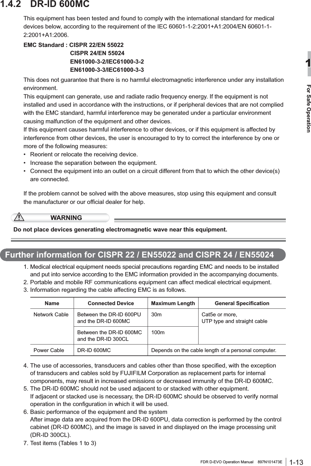
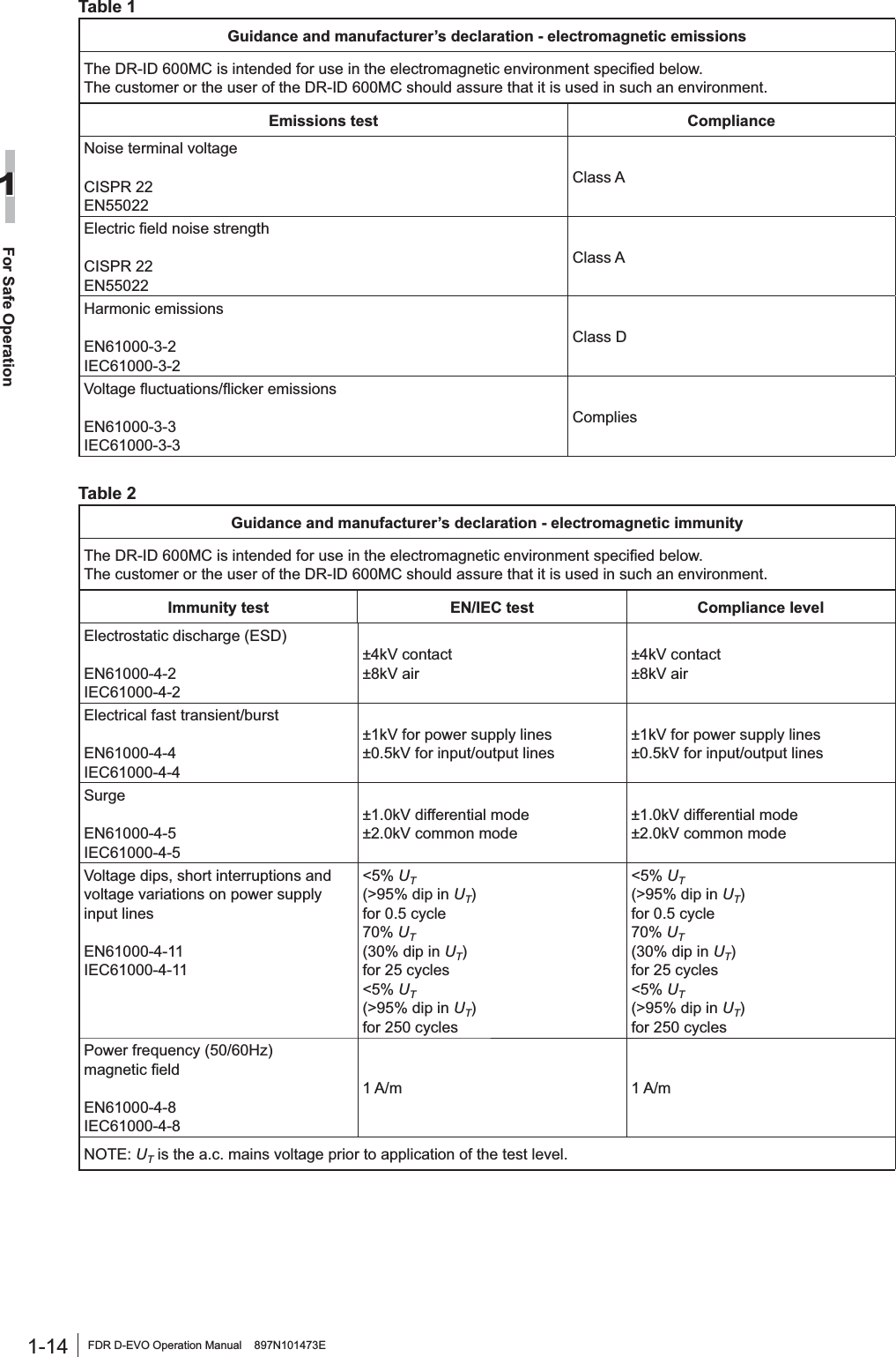
![1-11FDR D-EVO Operation Manual 897N101473EFor Safe Operation1Table 3*XLGDQFHDQGPDQXIDFWXUHU¶VGHFODUDWLRQHOHFWURPDJQHWLFLPPXQLW\7KH'5,'38DQGWKH'5,'&/DUHLQWHQGHGIRUXVHLQWKHHOHFWURPDJQHWLFHQYLURQPHQWVSHFL¿HGEHORZThe customer or the user of the DR-ID 600PU and the DR-ID 300CL should assure that they are used in such an environment.Immunity test IEC 60601 test level Compliance level (OHFWURPDJQHWLFHQYLURQPHQWJXLGDQFHConducted RFIEC61000-4-6Radiated RFIEC61000-4-33 Vrms150 kHz to 80 MHz3 V/m80 MHz to 2.5 GHz3 Vrms3 V/mPortable and mobile RF communications equipment should be used no closer to any part of the DR-ID 600PU and the DR-ID 300CL, including cables, than the recommended separation distance calculated from the equation applicable to the frequency of the transmitter.Recommended separation distanced = 1.2d = 1.2 80 MHz to 800 MHzd = 2.3 800 MHz to 2.5 GHzwhereP is the maximum output power rating of the transmitter in watts (W) according to the transmitter manufacturer and d is the recommended separation distance in metres (m).)LHOGVWUHQJWKVIURP¿[HG5)WUDQVPLWWHUVDVdetermined by an electromagnetic site survey,ashould be less than the compliance level in each frequency range.bInterference may occur in the vicinity of equipment PDUNHGZLWKWKHIROORZLQJV\PERO127($W0+]DQG0+]WKHKLJKHUIUHTXHQF\UDQJHDSSOLHV127(7KHVHJXLGHOLQHVPD\QRWDSSO\LQDOOVLWXDWLRQV(OHFWURPDJQHWLFSURSDJDWLRQLVDIIHFWHGE\DEVRUSWLRQDQGUHÀHFWLRQIURPVWUXFWXUHVREMHFWVDQGSHRSOHD )LHOGVWUHQJWKIURP¿[HGWUDQVPLWWHUVVXFKDVEDVHVWDWLRQVIRUUDGLRFHOOXODUFRUGOHVVWHOHSKRQHVDQGODQGmobile radios, amateur radio, AM and FM radio broadcast and TV broadcast cannot be predicted theoretically with DFFXUDF\7RDVVHVVWKHHOHFWURPDJQHWLFHQYLURQPHQWGXHWR¿[HG5)WUDQVPLWWHUVDQHOHFWURPDJQHWLFVLWHVXUYH\VKRXOGEHFRQVLGHUHG,IWKHPHDVXUHG¿HOGVWUHQJWKLQWKHORFDWLRQLQZKLFKWKH'5,'38DQGWKH'5,'&/are used exceeds the applicable RF compliance, the DR-ID 600PU and the DR-ID 300CL should be observed to verify normal operation. If abnormal performance is observed, additional measures may be necessary, such as reorienting or relocating the DR-ID 600PU and the DR-ID 300CL.E 2YHUWKHIUHTXHQF\UDQJHN+]WR0+]¿HOGVWUHQJWKVKRXOGEHOHVVWKDQ9P](https://usermanual.wiki/Fuji-Film/01000001/User-Guide-1413644-Page-21.png)
![1-12 FDR D-EVO Operation Manual 897N101473EFor Safe Operation1Table 4Recommended separation distances between3RUWDEOHDQGPRELOH5)FRPPXQLFDWLRQVHTXLSPHQWDQGWKH'5,'38DQGWKH'5,'&/The DR-ID 600PU and the DR-ID 300CL are intended for use in the electromagnetic environment in which radiated RF disturbances are controlled.The customer or the user of the DR-ID 600PU and the DR-ID 300CL can help prevent electromagnetic interference by maintaining a minimum distance between portable and mobile RF communications equipment (transmitters) and the DR-ID 600PU and the DR-ID 300CL as recommended below, according to the maximum output power of the communications equipment.Rated maximum output power of transmitterW6HSDUDWLRQGLVWDQFHDFFRUGLQJWRIUHTXHQF\RIWUDQVPLWWHUm150 kHz to 80 MHzd = 1.280 MHz to 800 MHzd = 1.2800 MHz to 2.5 GHzd = 2.30.01 0.12 0.12 0.230.1 0.38 0.38 0.731 1.2 1.2 2.310 3.8 3.8 7.3100 12 12 23For transmitters rated at a maximum output power not listed above, the recommended separation distance d in metres (m) can be estimated using the equation applicable to the frequency of the transmitter, where P is the maximum output power rating of the transmitter in watts (W) according to the transmitter manufacturer.127( $W0+]DQG0+]WKHVHSDUDWLRQGLVWDQFHIRUWKHKLJKHUIUHTXHQF\UDQJHDSSOLHV127( 7KHVHJXLGHOLQHVPD\QRWDSSO\LQDOOVLWXDWLRQV (OHFWURPDJQHWLFSURSDJDWLRQLVDIIHFWHGE\DEVRUSWLRQDQGUHÀHFWLRQIURPVWUXFWXUHVREMHFWVDQGSHRSOH](https://usermanual.wiki/Fuji-Film/01000001/User-Guide-1413644-Page-22.png)

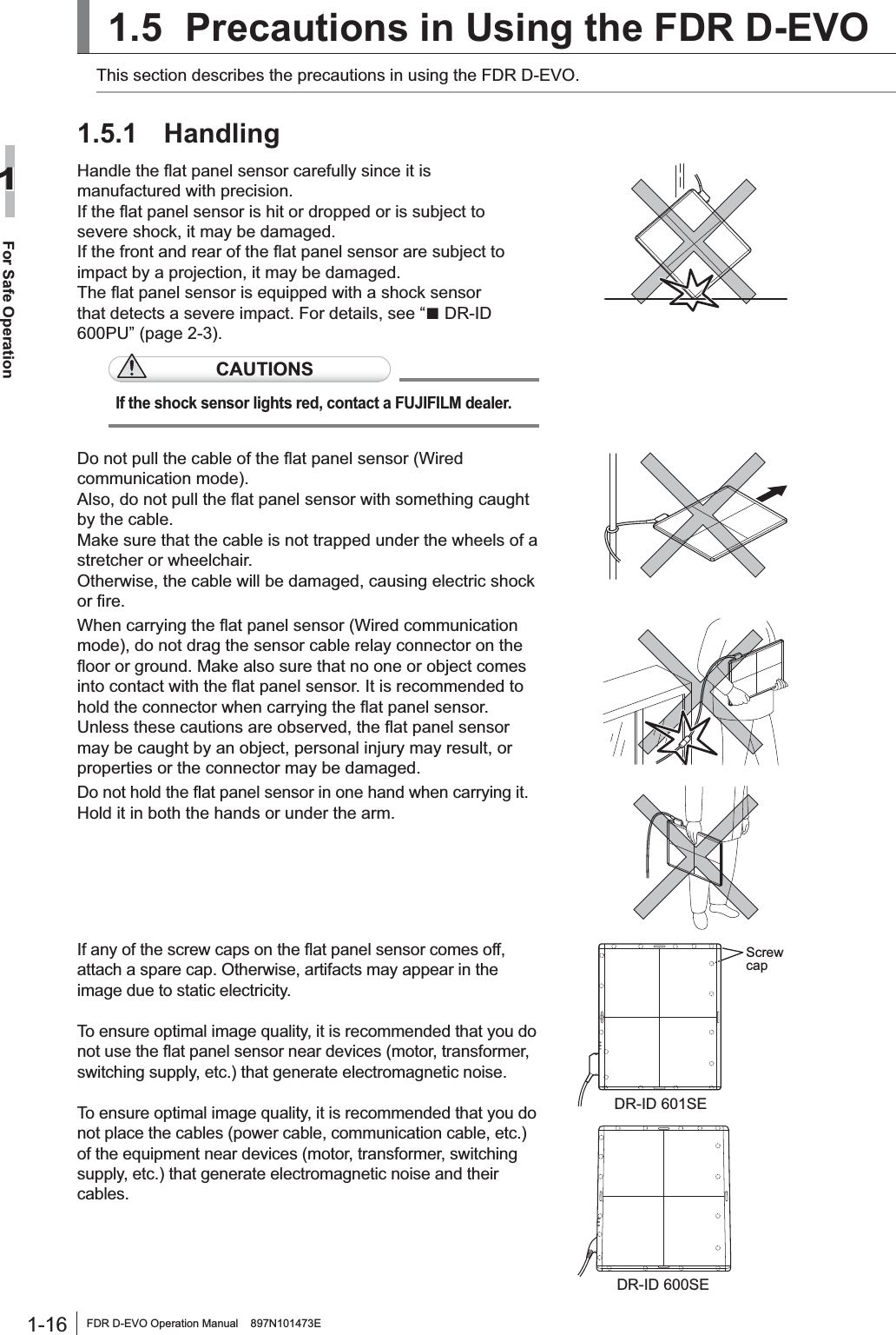
![1-17FDR D-EVO Operation Manual 897N101473EFor Safe Operation11.5.2 Before ExposureThe use of an air-conditioner may dramatically changes the temperature of the room where the system is installed. This may cause dew condensation on the system, resulting in quality problems. When an air-conditioner is used, change the temperature gradually to avoid temperature variation in order not to cause dew condensation.,IDQH[SRVXUHLVPDGHZLWKWKHIURQWDQGUHDURIWKHÀDWSDQHOsensor facing the other way round, re-exposure and electric parts may be damaged.Exposure plane of the flat panel sensor'RQRWXVHWKHÀDWSDQHOVHQVRUIRUWKHUDGLRJUDSKLFH[DPLQDWLRQVWDQGHTXLSSHGZLWKDQDXWRPDWLFloading function. 'XULQJ([SRVXUHBefore making an exposure, make sure that exposure conditions most appropriate for this system are set.Do not apply an excessive force to the exposure plane. 7KHVHQVRULQVLGHWKHÀDWSDQHOVHQVRUPD\EHGDPDJHG<Load restriction>(QWLUHVXUIDFHORDGNJ/RFDOORDG'5,'6(NJ¡PP'5,'6(NJ¡PP8VHWKHÀDWSDQHOVHQVRURQDÀDWÀRRURUSODWIRUPWhen an excessive force is applied to the unit when it LVWLOWHGWKHVHQVRULQVLGHWKHÀDWSDQHOVHQVRUPD\EHdamaged. 'XULQJ&OHDQLQJTo clean the outer surfaces, use commercially available ethanol papers for disinfection or a cleaning cloth tightly wrung out of ethanol (or diluted neutral detergent).CAUTIONSƔ 'RQRWXVHDQH[FHVVLYHDPRXQWRIHWKDQRORUQHXWUDOGHWHUJHQWDVGRLQJVRPD\DOORZWKHOLTXLGWRHQWHUIURPWKHJDSRQWKHRXWHUVXUIDFHVUHVXOWLQJLQWKHGDPDJHWRWKHÀDWSDQHOsensor, or cause the labels to come off.Ɣ 'RQRWXVHDVROYHQWVXFKDVWKLQQHURUEHQ]LQHDVLWFRUURGHVWKHRXWHUVXUIDFHV 6WRUDJH:KHQWKHÀDWSDQHOVHQVRULVQRWLQXVHVWRUHWKHGHYLFHLQDSODFHZKHUHLWGRHVQRWIDOORUGURS](https://usermanual.wiki/Fuji-Film/01000001/User-Guide-1413644-Page-27.png)
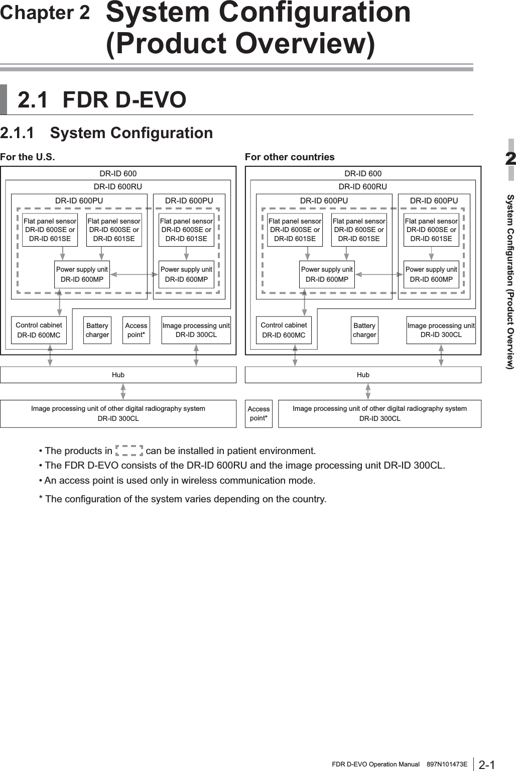
![2-4 FDR D-EVO Operation Manual 897N101473E6\VWHP&RQILJXUDWLRQ3URGXFW2YHUYLHZ2ŶDR-ID 600MCMain switch/power status LEDControl cabinet (DR-ID 600MC)Name DescriptionControl cabinet(DR-ID 600MC)$SHUVRQDOFRPSXWHUXVHGIRUFRQWUROOLQJWKHÀDWSDQHOVHQVRUDQGperforming image processing. Main switch Supplies the power to the control cabinet.Power status LED Displays ON/OFF of the control cabinet.Ŷ %DWWHU\FKDUJHU2SWLRQDOBattery chargerName DescriptionBattery charger &KDUJHVWKHEDWWHU\SDFNRSWLRQDOIRUWKHÀDWSDQHOVHQVRU'5,'601SE). Three packs can be charged at the same time.Charge status indicator LED Indicates charge status.ŶAccess point3URGXFWFRPSOLDQWZLWK,(&8/36(RU-,6Compliant with IEEE802.11n [W52] (in the 5.2GHz band) /36, 40, 44, 48ch:/$1LQWHUIDFH%$6(7%$6(7;PLQLPXPUHTXLUHPHQWV/$1LQWHUIDFH%$6(7%$6(7;PLQLPXPUHTXLUHPHQWV$YDLODEOH26/LQX[Compliant with ULCompliant with FCC part15ŶDR-ID 300CL For the unit names and functions of the DR-ID 300CL, see the “DR-ID 300CL Operation Manual”.](https://usermanual.wiki/Fuji-Film/01000001/User-Guide-1413644-Page-36.png)
![3-1FDR D-EVO Operation Manual 897N101473EBasic Operation3Chapter 3 Basic Operation 3UHSDULQJWKH)ODW3DQHO6HQVRU7KLVVHFWLRQGHVFULEHVKRZWRSUHSDUHWKHÀDWSDQHOVHQVRU3.1.1 Type of Flat Panel Sensor'5,'6(:LUHOHVVFRPPXQLFDWLRQPRGHRUZLUHGFRPPXQLFDWLRQPRGHLVDYDLODEOH:KHQused in wireless communication mode, an access point*1, battery pack (optional) and battery charger (optional) are required.*1 In the countries other than the U.S., an access point is not included as a component of the system. For GHWDLOVLQFOXGLQJLQVWDOODWLRQFRQVXOWRXURI¿FLDOGHDOHUProduct compliant with IEC60950, UL60950, PSE or JISCompliant with IEEE802.11n [W52] (in the 5.2GHz band) /36, 40, 44, 48ch:/$1LQWHUIDFH%$6(7%$6(7;PLQLPXPUHTXLUHPHQWV/$1LQWHUIDFH%$6(7%$6(7;PLQLPXPUHTXLUHPHQWV$YDLODEOH26/LQX[Compliant with ULCompliant with FCC part15CAUTIONSUse only one access point. A communication error may occur if two units or more are used.'5,'6(:LUHGFRPPXQLFDWLRQPRGH3.1.2 Number of the Connectable Flat Panel Sensors7RHQDEOHWKHÀDWSDQHOVHQVRULWV,'QHHGVWREHUHJLVWHUHGLQDGYDQFHE\D)8-,),/0GHDOHU8SWR¿YHÀDWSDQHOVHQVRUVFDQEHUHJLVWHUHG8SWRWKUHHÀDWSDQHOVHQVRUV2 can be connected to the power supply unit at the same time.:KHQWKUHHÀDWSDQHOVHQVRUVDUHFRQQHFWHGDWWKHVDPHWLPHWZRSRZHUVXSSO\XQLWDUHUHTXLUHGFlat panel sensor(DR-ID 600SE or DR-ID 601SE)Image processing unit(DR-ID 300CL)Access pointControl cabinet(DR-ID 600MC)Power supply unit (DR-ID 600MP)HubFlat panel sensor(DR-ID 600SE or DR-ID 601SE)Flat panel sensor(DR-ID 600SE or DR-ID 601SE)Power supply unit (DR-ID 600MP) &RQQHFWLQJ'LVFRQQHFWLQJWKH)ODW3DQHO6HQVRU'5,'601SE) ConnectorWhen used in wireless communication mode, disconnect the connector.1Disconnect the connector.Press the latches on both sides of the connector.2Connect the connector.Press the connector into the insertion section.*Frequency Tolerance: ±20ppm](https://usermanual.wiki/Fuji-Film/01000001/User-Guide-1413644-Page-39.png)
![3-4Basic Operation3FDR D-EVO Operation Manual 897N101473E[2] Bed typeCAUTIONS:KHQLQVHUWLQJWKHÀDWSDQHOVHQVRUWRWKHUDGLRJUDSKLFH[DPLQDWLRQVWDQGdirect the exposure plane upwards.1 3XOORXWWKHWUD\E\XVLQJWKHKDQGOHTray2 3XOOWKHFDVVHWWHVWRSSHUDQGVHWWKHÀDWSDQHOVHQVRUVRWKDWLWVFHQWHUPDUNLVDOLJQHGZLWKWKHFHQWHURIWKHVWRSSHU3RVLWLRQWKHFRQQHFWRURIWKHÀDWSDQHOVHQVRUDVVKRZQLQWKH¿JXUHEHORZCassettestopperConnectorCenter mark:KHQVHWWLQJWKHÀDWSDQHOVHQVRUhorizontally, position the connector as VKRZQLQWKH¿JXUHEHORZConnector3 3XVKWKHWUD\EDFNLQWRSODFHE\XVLQJWKHKDQGOHDIWHUVHWWLQJWKHÀDWSDQHOVHQVRU4 :KHQUHPRYLQJWKHÀDWSDQHOVHQVRUHold the handle and pull out the tray. Remove the ÀDWSDQHOVHQVRUZKLOHSXOOLQJWKHFDVVHWWHVWRSSHUand then push the tray back into place. &KDQJLQJWKH'LUHFWLRQRIWKH)ODW3DQHO6HQVRUConnector7KHGLUHFWLRQRIWKHFRQQHFWRURIWKHÀDWSDQHOVHQVRUFDQEHFKDQJHGGHSHQGLQJRQKRZLWLVinserted into the radiographic examination stand. To change the direction, contact a FUJIFILM dealer.When shipped After changing the direction](https://usermanual.wiki/Fuji-Film/01000001/User-Guide-1413644-Page-42.png)
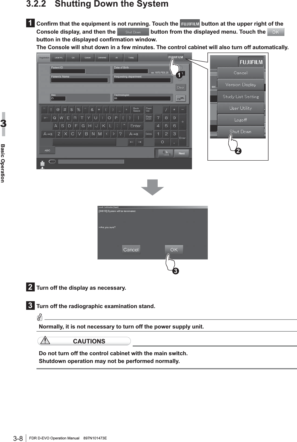
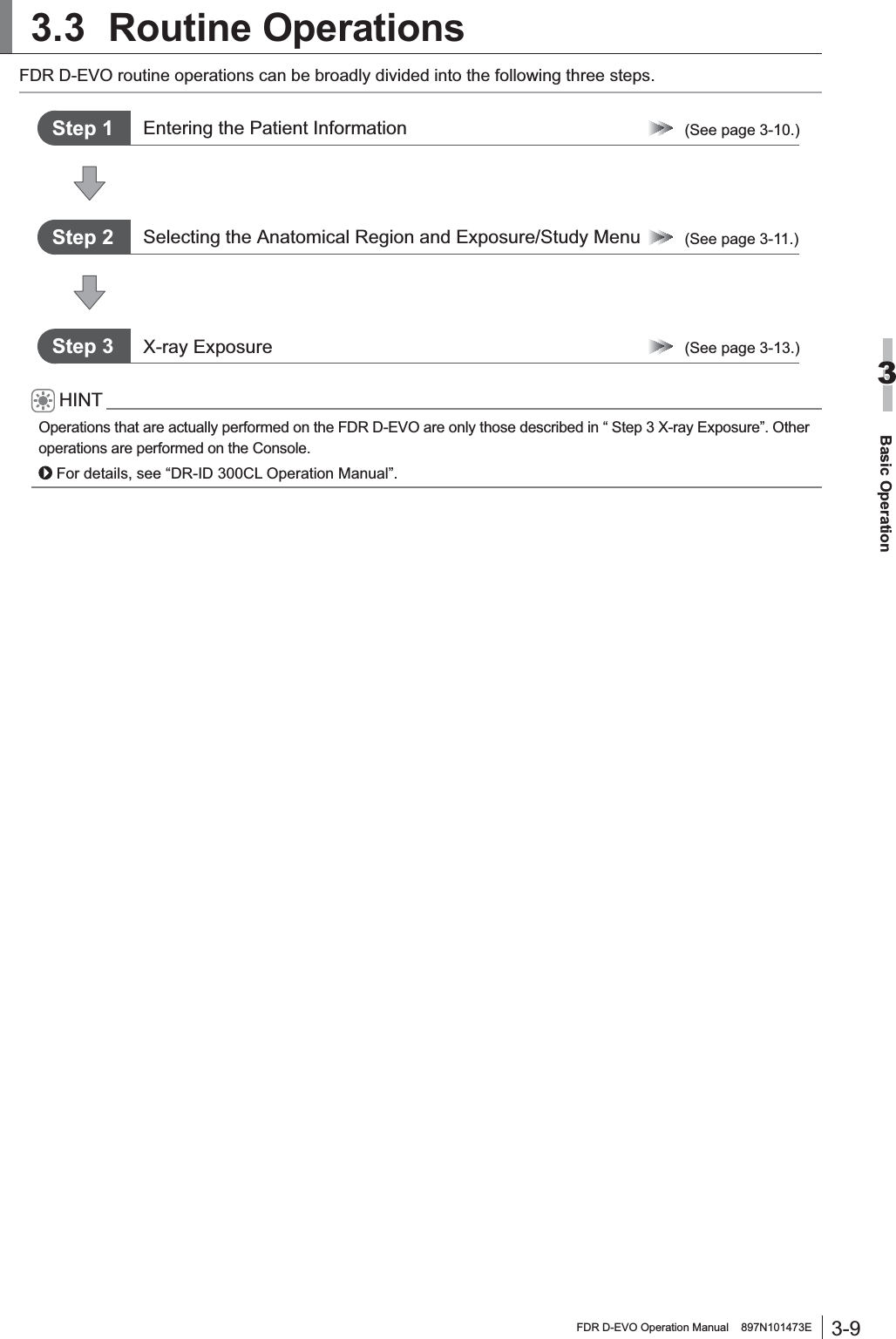
![3-7FDR D-EVO Operation Manual 897N101473EBasic Operation3 6WDUWLQJ8SDQG6KXWWLQJ'RZQWKHSystemThis section explains how to start up and shut down the system. To start up the system, operations are required on the FDR D-EVO main unit and on the Console. To shut down the entire system, operations are required only on the Console. 6WDUWLQJ8SWKH6\VWHP1Press the ON side of the main switch of the power supply unit, if its power status LED is not lit.2 $IWHUFRQ¿UPLQJWKHIROORZLQJLWHPVSUHVVWKHSRZHUVZLWFKIRUWKH&RQVROHWRVWDUWWKHinitialization process.$OOFDEOHVVKRXOGEHFRQQHFWHGSURSHUO\1RPHGLDVKRXOGEHLQVHUWHGLQWRWKH)''The control cabinet starts up automatically.CAUTIONS,IWKHSRZHUVWDWXV/('RIWKHSRZHUVXSSO\XQLWGRHVQRWFRPHRQDIWHUWXUQLQJRQWKHConsole, turn on the control cabinet.3 7XUQRQWKHUDGLRJUDSKLFH[DPLQDWLRQVWDQG4 $IWHUGLVSOD\LQJWKHVWDUWXSSURJUHVVLRQVWDWXVVRIWZDUHYHUVLRQDQGLQLWLDOL]DWLRQSURJUHVVLRQstatus, the activation completion screen below will be displayed on the Console.Activation completion screen of the ConsoleCAUTIONSAn error occurs if the system is started up immediately after shutdown.7RUHVWDUWWKHV\VWHPPDNHVXUHWKDWWKHSRZHUVWDWXV/('RIWKHSRZHUVXSSO\XQLWLVRIIDQGthen press the power switch for the Console.](https://usermanual.wiki/Fuji-Film/01000001/User-Guide-1413644-Page-45.png)
![4-1FDR D-EVO Operation Manual 897N101473E7URXEOHVKRRWLQJ4Chapter 47URXEOHVKRRWLQJ4.1:KHQD0HVVDJH$SSHDUVRQWKH&RQVROHThis section describes the warning dialog box and error messages. If an error which cannot be handled or the same error recurs frequently, contact a FUJIFILM dealer. If an error of unknown cause occurs, do not continue the operation and contact a FUJIFILM dealer. >@,IDZDUQLQJGLDORJER[DSSHDUVIf a communication error or an unexpected error has occurred, a warning dialog box pops up on the screen. In such a case, after checking error details and closing the box, take appropriate action immediately. Be sure not to continue the operation of the Console without taking an appropriate action.If any operation is performed while a warning dialog box is displayed, another screen may be displayed, hiding the dialog box behind. In this case, press the [Enter] key to close the hidden box.[2] If a communication error occurs between the Console and the connected DR system7KHHUURUPHVVDJHER[,'LVGLVSOD\HGQRWRQO\ZKHQWKH&RQVROHVWDUWVXSEXWDOVRZKHQDcommunication error occurs.When the problem is not solved within a short time after the message box is displayed, perform the following procedure.1 6HOHFW>2.@RQWKHPHVVDJHER[2 &KHFNLIWKHHTXLSPHQWFRQQHFWHGZLWKWKH&RQVROHLVWXUQHGRQIf any equipment is turned off, turn it on and wait for a while.3If the problem is not solved, shut down the Console. 4 0DNHVXUHWKDWWKHSRZHUVWDWXV/('RIWKHFRQWUROFDELQHWLVRIIDQGWKHQUHVWDUWWKH&RQVROHIf the power status LED of the control cabinet does not turn off even after approximately PLQXWHVKDYHSDVVHGIROORZLQJWKHVKXWGRZQRIWKH&RQVROHSUHVVDQGKROGWKHPDLQswitch of the control cabinet. When the Console is restarted and the same error message box is displayed, contact a FUJIFILM dealer.](https://usermanual.wiki/Fuji-Film/01000001/User-Guide-1413644-Page-55.png)
![4-2 FDR D-EVO Operation Manual 897N101473E7URXEOHVKRRWLQJ4[3] If an error occurs on the ConsoleIf an error occurs on the Console, an error message box is displayed on the screen.In such a case, check error details and select [OK] in the box, and then take an appropriate action.[4] If an error occurs on an output destination deviceIf an error occurs on an output destination device, is displayed at the upper right of the screen. In such a case, operate as follows.Select .An error display box is displayed.Check the connection status, select , and then take an appropriate action.“Error display box“](https://usermanual.wiki/Fuji-Film/01000001/User-Guide-1413644-Page-56.png)
![4-3FDR D-EVO Operation Manual 897N101473E7URXEOHVKRRWLQJ44.2 How to Cope with an Error...>@:KHQWKHV\VWHPKDQJVXSIf an inappropriate processing is performed while this equipment is operating, the screen may freeze and the system may hang up (processing disabled). In that case, shut down the equipment forcibly according to the following procedure, and then restart it.,IWKHVFUHHQIUHH]HVDQGDKDQJXSRFFXUVUHPRYHWKHNH\ERDUGDQGPRXVHDQGUHFRQQHFWthem. If this operation does not solve the problem, restart the Console.1 3UHVVWKH>&WUO@>$OW@>'HO@NH\VVLPXOWDQHRXVO\2 ³:LQGRZV6HFXULW\´LVGLVSOD\HGSelect [Start Task Manager].3 ³:LQGRZV7DVN0DQDJHU´LVGLVSOD\HGSelect “IIPMAIN.exe” in the list in the “Processes” tab, and then click [End Process].4 7KHPHVVDJHER[LVGLVSOD\HGClick [End Process] to terminate the Console.Depending on equipment status, an error message may not be displayed.5 7KHGHVNWRSVFUHHQRIWKHRSHUDWLQJV\VWHP:LQGRZV9LVWDLVGLVSOD\HGClose the “Windows Task Manager window”, and then select the [Start] button at the lower left of the screen. Select [Restart] from the displayed menu.CAUTIONSƔ 0DNHVXUHWRVKXWGRZQWKHV\VWHPIROORZLQJWKHDERYHSURFHGXUHVLQFDVHRIDKDQJXSRIthe Console. If the personal computer is turned off without shutdown, an error may occur on the computer.Ɣ 1RWHWKDWIRUFLEOHVKXWGRZQSURFHVVLQJRIWKHHTXLSPHQWLVDQHPHUJHQF\DFWLRQ'RQRWXVHthis action under normal situations.6Press and hold the main switch of the control cabinet to turn it off.7Press the OFF side of the main switch of the power supply unit.](https://usermanual.wiki/Fuji-Film/01000001/User-Guide-1413644-Page-57.png)
![4-4 FDR D-EVO Operation Manual 897N101473E7URXEOHVKRRWLQJ4>@:KHQWKH&RQVROHLVWXUQHGRIIGXHWRDQHOHFWULFDORXWDJHWhen the Console is turned off due to an electrical outage, etc., take the following actions according the condition when the power comes back on.Ŷ ,IWKHSRZHUFRPHVEDFNRQVRRQDIWHUDQHOHFWULFDORXWDJHWait until the Console restarts.When the Console has restarted, shut down the Console by following the normal procedure.For details of system shutdown, see the “DR-ID 300CL Operation Manual”.To restart the Console, follow the procedure for the system startup.>@,IDKDUGGLVNRIWKH&RQVROHLVGDPDJHGIf one of the hard disks is damaged, a window indicating so will appear. In such a case, press the )NH\DQGFRQWDFWRXURI¿FLDOGHDOHU>@,IDZKLWHLPDJHLVGLVSOD\HGDIWHUDQH[SRVXUHIf a white image is displayed, a LAN communication error may have occurred. &KHFNLIWKH/$1FRPPXQLFDWLRQFRQQHFWRUVDUHSURSHUO\FRQQHFWHGEHWZHHQWKHÀDWSDQHOVHQVRUand the power supply or and between the power supply unit and the control cabinet. Make an H[SRVXUHDJDLQDIWHUFRQ¿UPDWLRQ>@3UHFDXWLRQVIRURSHUDWLQJWKHV\VWHPZKHQ³,QLWLDOL]LQJ´RU³&KDQJLQJ)3'´LVGLVSOD\HGLQWKH&RQVROH¶VRSHUDWLQJVWDWXVGLVSOD\DWWKHWLPHRIUHSODFLQJWKHÀDWSDQHOVHQVRU:KHQUHSODFLQJWKHÀDWSDQHOVHQVRUE\XVLQJWKHPDLQVZLWFKRIWKHSRZHUVXSSO\XQLWRUWKHoptional remote switch, “Initializing” or “Changing FPD” is displayed in the operating status display of the Console. While either of the status messages is displayed, you cannot register/select exposure menu(s), change the selector, etc. Perform the operations above after the status message disappears.>@,IZLUHOHVVFRPPXQLFDWLRQZLWKWKHÀDWSDQHOVHQVRU'5,'601SE) is not possible,IWKHÀDWSDQHOVHQVRULVQRWUHFRJQL]HGLQZLUHOHVVFRPPXQLFDWLRQPRGHFRQQHFWWKHFRQQHFWRUWRuse the system in wired communication mode.>@,IZLUHOHVVFRPPXQLFDWLRQPRGHLVGLVDEOHGZKHQXVLQJWKHÀDWSDQHOVHQVRU'5,'6(If wireless communication is interrupted, an error message prompting reconnection is displayed after 30 seconds. Select “Yes”. If connection is not established even after the selection is made, connect the connector and retry the connection.](https://usermanual.wiki/Fuji-Film/01000001/User-Guide-1413644-Page-58.png)
 14” × 17” (b) 17” × 14” (c) 14” × 14”one-image output one-image output one-image output(14” × 17” film) (14” × 17” film)(14” × 17” film)ID informationImageImageID informationID informationImage(d) 18 × 43cm (e) 18 × 43cm (f) 18 × 43cmone-image output two-image output two-image output(14” × 17” film)IDinformationIDinformationIDinformationIDinformation(26 × 36cm film)(26 × 36cm film)ImageImageImageImageImage(g) Two-image outputID informationImage(26 × 36cm film)For one-image output using 17” × 14”, 14” × 17”, 14” × 14” or 18 × 43cm, images are output on 14” î´¿OP,QRWKHUFDVHVLPDJHVDUHRXWSXWRQîFP¿OP'HSHQGLQJRQWKHSULQWHUFRQQHFWHGRU&RQVROHVRIWZDUHYHUVLRQXVHGLPDJHRXWSXWVLQWKHIROORZLQJIRUPDWVDUHDYDLODEOHƔ VL]HRXWSXWRI´î´LPDJHRQ´î´¿OPƔ VL]HRXWSXWRI´î´LPDJHRQ´î´¿OPDVZHOODVUHGXFHGLPDJHRXWSXWRQ¿OPVRIRWKHUVL]HVƔ VL]HRXWSXWRI´î´LPDJHRQ´î´¿OP](https://usermanual.wiki/Fuji-Film/01000001/User-Guide-1413644-Page-62.png)
![A-3FDR D-EVO Operation Manual 897N101473EAppendix A Specifications$ 5HGXFHG(TXLYDOHQW'5,'3HDNUHGXFHGHTXLYDOHQWRQWKHIURQWSDQHORIWKHÀDWSDQHOVHQVRUPP$OA.1.4 Power Supply ConditionsŶDR-ID 600PU 5DWHGYROWDJH9a ,QSXWFXUUHQW $ )UHTXHQF\ +]ŶDR-ID 600MC* 5DWHGYROWDJH9a ,QSXWFXUUHQW $ )UHTXHQF\ +]* Since the DR-ID 600MC is general-purpose electrical equipment, the electric rating above is an example. A.1.5 Environmental ConditionsŶDR-ID 600PU2SHUDWLQJ&RQGLWLRQV 7HPSHUDWXUH &5+&5+ +XPLGLW\ 5+&5+&QRGHZFRQGHQVDWLRQ $WPRVSKHULFSUHVVXUHK3DK3D1RQRSHUDWLQJ&RQGLWLRQV (Environmental conditions under which power can be supplied) 7HPSHUDWXUH &&QRGHZFRQGHQVDWLRQ +XPLGLW\ 5+5+QRGHZFRQGHQVDWLRQ $WPRVSKHULFSUHVVXUHK3DK3DŶDR-ID 600MC2SHUDWLQJ&RQGLWLRQV 7HPSHUDWXUH && +XPLGLW\ 5+5+QRGHZFRQGHQVDWLRQ $WPRVSKHULFSUHVVXUHK3DK3D1RQRSHUDWLQJ&RQGLWLRQV (Environmental conditions under which power can be supplied) 7HPSHUDWXUH && +XPLGLW\ 5+5+QRGHZFRQGHQVDWLRQ $WPRVSKHULFSUHVVXUHK3DK3D](https://usermanual.wiki/Fuji-Film/01000001/User-Guide-1413644-Page-63.png)
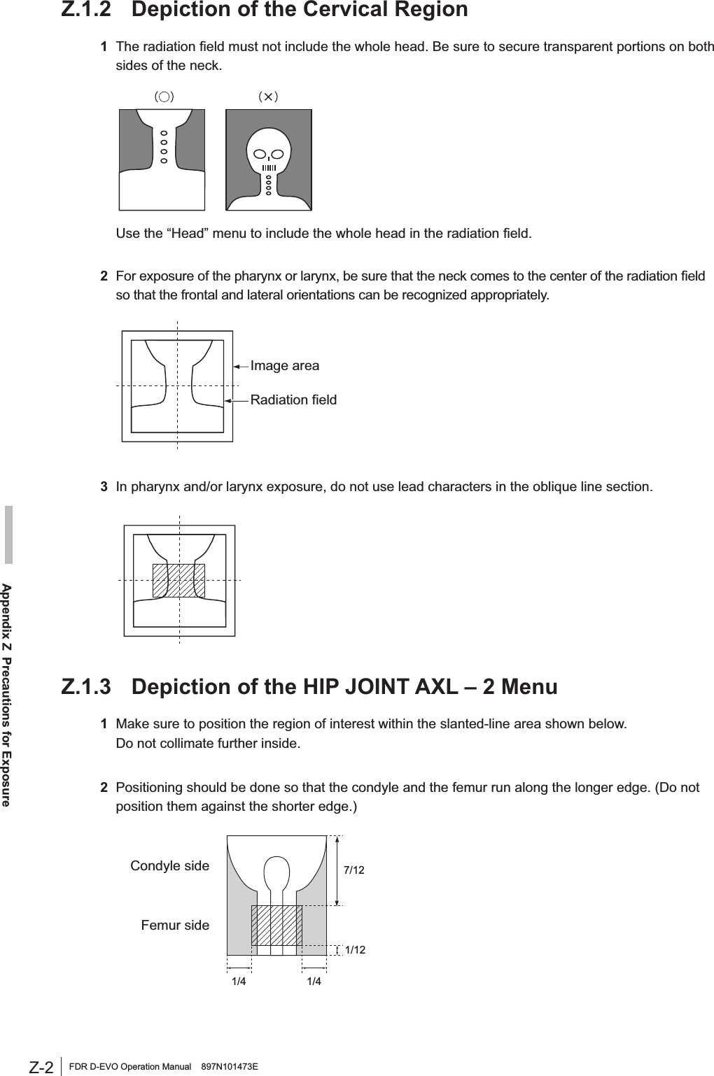
![Z-1FDR D-EVO Operation Manual 897N101473EAppendix Z Precautions for ExposureAppendix Z Precautions for ExposureZ1.Precautions for Exposure in AUTO MODEIn AUTO MODE, stable image output can be obtained by means of the following.5DGLDWLRQ¿HOG(2) EDR image data analysis(3) Detailed depiction of the cervical regionHowever, problems may arise due to differences in the multiple diaphragms or scattered rays of the X-ray equipment. For such problems, contact a FUJIFILM dealer and use other recording modes, such as SEMI-AUTO MODE or FIX MODE.Z.1.1 Radiation Field1'RQRWVHWWKHUDGLDWLRQ¿HOGH[WUHPHO\VPDOO%HVXUHWRVXEMHFWRQHWKLUGRUPRUHRIWKHOHQJWKRIeach side of the bucky of the DR system to X-ray exposure.20DNHVXUHWKDWQRQHRIWKHVLGHVRIWKHUDGLDWLRQ¿HOGRYHUODSZLWKWKHFRQWUDVWPHGLXP(UURUVZLOOresult if they overlap. $YDLODEOHIRU(DFK$QDWRPLFDO5HJLRQ0HWKRGPlain Contrast Medium 7RPRJUDSK\Head 4441HFN 44–Chest 4 4 (1 for esophagus) –Abdomen 4 4 (1 for stomach and intestines) –Pelvis 44–3Notes on PRIEF[PRIEF 4] Used, with some exceptions, for both plain and contrast medium exposure menus, from the head to the pelvis. The diaphragm shape will be any convex polygon, including rectangles, circles, ellipses, tracks, etc.[PRIEF 1] Used with esophagus, stomach and intestines contrast medium menus.](https://usermanual.wiki/Fuji-Film/01000001/User-Guide-1413644-Page-67.png)
![Z-3FDR D-EVO Operation Manual 897N101473EAppendix Z Precautions for Exposure= ('5,PDJH'DWD$QDO\VLV1Image unevenness appearing when the grid used in exposure is not positioned correctly in terms of the bulb, when there are shadows from clothing, or when X-ray radiation of the X-ray exposure area is uneven is a problem that arises during EDR image data analysis, which cause unstable density on the image.Avoid such unevenness in the X-ray exposure area as far as possible.2If the target includes such materials as gypsum, denture, etc., stable density may not be obtained, EHFDXVHVXFKPDWHULDOVPDNHLWGLI¿FXOWWRDQDO\]H('5LPDJHGDWDIn such cases, use S-Shift/C-Shift or FIX MODE.3The EDR performs processing for the image area trimmed by the DR system. :KHQXVLQJOHDGFKDUDFWHUVRUPHWDOVIRUPHDVXUHPHQWSODFHWKHPLQVLGHWKHUDGLDWLRQ¿HOGDQGthen make an exposure.4Precautions when using AUTO MODE.Auto mode PrecautionsIAs this mode is available for extracting information on the skin, secure the positioning so that the direct X-rays are incident to an area other than the target.II No special precautions.III Be sure to use a Ba contrast medium.IV1 Be sure to secure the positioning so that the X-rays are incident to the area directly outside the target.$VWKHUHDGLQJODWLWXGHLV¿[HGLWLVQHFHVVDU\WRFRQWUROWKHWXEHYROWDJHDFFRUGLQJWRWKHthickness of the target, as usual.V$VWKHUHDGLQJODWLWXGHLV¿[HGLWLVQHFHVVDU\WRFRQWUROWKHWXEHYROWDJHDFFRUGLQJWRWKHthickness of the target, as usual.VI No special precautions.VII No special precautions.](https://usermanual.wiki/Fuji-Film/01000001/User-Guide-1413644-Page-69.png)
![Z-7FDR D-EVO Operation Manual 897N101473EAppendix Z Precautions for ExposureZ.5 Other PrecautionsZ.5.1 Precautions for Exposure of a Subject in Relatively /DUJH&RQWUDVW1Exposures using a contrast medium may cause artifacts around it.2When exposing a subject with any metal objects implanted, artifacts may appear around them.3For exposures with objects of large X-ray absorption, such as lead characters and metals for measurement, artifacts may appear around them. Place such objects outside a subject.Z.5.2 Precautions for DR System*HQHUDOO\ZKHQSHUIRUPLQJDKLJKVHQVLWLYLW\H[SRVXUHVKRUWO\DIWHUDQH[SRVXUHWKDWWKHÀDWpanel sensor excessively receives direct X-ray, the output image may contain image lags of the previous exposure. This phenomenon rarely occurs and does not occur insofar as normal sensitivity exposures are performed.Exposures at longer intervals can reduce occurrences of this phenomenon. Also observe precautions as follows. &RQWLQXRXVKLJKVHQVLWLYLW\H[SRVXUHVWRYHUWHEUDOERG\SDUWFKHVWOXPEDUVSLQHVKRXOGEHperformed at longer intervals than normal exposures. $KLJKVHQVLWLYLW\H[SRVXUHVKRUWO\DIWHUDKLJKGRVHH[SRVXUHVKRXOGEHSHUIRUPHGDWVXI¿FLHQWO\long interval. :KHQSHUIRUPLQJKLJKGRVHH[SRVXUHVUHSHDWHGO\GRQRWXVHFROOLPDWLRQRIWKHUDGLDWLRQ¿HOGlead characters or metals for measurement at the same position.= 3UHFDXWLRQVIRU$VVXULQJWKH5DGLDWLRQ)LHOGCAUTIONS,WLVLPSRUWDQWWRUHDGWKHIROORZLQJEHIRUHXVLQJWKH)'5'(92GLJLWDOGHWHFWRUFOLQLFDOO\The FDR D-EVO is a digital X-ray detector designed for use both within and outside of a standard UDGLRJUDSKLFEXFN\7KH)'5'(92PD\EHH[SRVHGWRDQ\¿HOGVL]HXSWRDQGLQFOXGLQJ´17” (35 FP)'5'(92PD\EHXVHGLQDQ\VLWXDWLRQZKHUHD¿OPFDVVHWWHPD\EHXVHGThe collimator will open to the full 14” 17” (35 43cm) size when the FDR D-EVO cassette is inserted in the bucky tray of X-ray systems with positive beam limitation (PBL). )ROORZWKH;UD\V\VWHPPDQXIDFWXUHU¶VLQVWUXFWLRQVWRDVVXUHWKHLQGLFDWHG¿HOGVL]HPDWFKHVDQGGRHVQRWH[FHHGWKHDFWXDOUDGLDWLRQ¿HOGVL]HIRUWKHDYDLODEOHUDQJHRI6,'VZ.5.4 Precautions Related to the X-ray Exposure TimeThe X-ray exposure time can be set within the range of 500msec to 3800msec at the time of installation.](https://usermanual.wiki/Fuji-Film/01000001/User-Guide-1413644-Page-73.png)