Fuji Film 01000001 D-EVO G35i User Manual 897N101473E Z72N2000E 101026
Fuji Film Corporation D-EVO G35i 897N101473E Z72N2000E 101026
Users Manual

897N101473E
This Operation Manual describes details on how to operate the FDR D-EVO and cautions
to be observed when operating it. Please read the Operation Manual thoroughly before
actually operating the FDR D-EVO along with “DR-ID 300CL Operation Manual” and
other manuals for the related products.
After reading this manual, store it nearby the FDR D-EVO so that you can see it whenever
necessary.
DIGITAL RADIOGRAPHY
FUJIFILM DR
(DR-ID 600)
Operation Manual
6st Edition: October 2010
For Safe Operation
System
&RQ¿JXUDWLRQ
(Product Overview)
Basic Operation
7URXEOHVKRRWLQJ
Daily Inspection and
Maintenance
Appendix
Maintenance and
Inspection

ii FDR D-EVO Operation Manual 897N101473E

iii
FDR D-EVO Operation Manual 897N101473E
Introduction
7KH:LUHG:LUHOHVV)'5'(92'5,'ÀDWSDQHOGHWHFWRUV\VWHPLVLQWHQGHGWRFDSWXUH
for display radiographic images of human anatomy. It is intended for use in general projection
UDGLRJUDSKLFDSSOLFDWLRQVZKHUHYHUFRQYHQWLRQDO¿OPVFUHHQRU&5V\VWHPVPD\EHXVHG7KH)'5
'(92'5,'LVQRWLQWHQGHGIRUPDPPRJUDSK\ÀXRURVFRS\WRPRJUDSK\DQGDQJLRJUDSK\
applications.
This Operation Manual includes descriptions of matters necessary when using the FDR D-EVO,
such as the equipment overview, operation procedures and precautions to observe, as well as daily
inspections and maintenance.
Accompanying documents were originally drafted in the English language.
Installation may only be conducted by authorized service personal.
CAUTIONS
1. No part or all of this manual may be reproduced in any form without prior permission.
7KHLQIRUPDWLRQFRQWDLQHGLQWKLVPDQXDOPD\EHVXEMHFWWRFKDQJHZLWKRXWSULRUQRWLFH
)8-,),/0&RUSRUDWLRQVKDOOQRWEHOLDEOHIRUPDOIXQFWLRQVDQGGDPDJHVUHVXOWLQJIURP
LQVWDOODWLRQUHORFDWLRQUHPRGHOLQJPDLQWHQDQFHDQGUHSDLUSHUIRUPHGE\RWKHUWKDQGHDOHUV
VSHFL¿HGE\)8-,),/0&RUSRUDWLRQ
)8-,),/0&RUSRUDWLRQVKDOOQRWEHOLDEOHIRUPDOIXQFWLRQVDQGGDPDJHVRI)8-,),/0
Corporation products due to products of other manufacturers not supplied by FUJIFILM
Corporation.
)8-,),/0&RUSRUDWLRQVKDOOQRWEHOLDEOHIRUPDOIXQFWLRQVDQGGDPDJHVUHVXOWLQJIURP
UHPRGHOLQJPDLQWHQDQFHDQGUHSDLUXVLQJUHSDLUSDUWVRWKHUWKDQWKRVHVSHFL¿HGE\
FUJIFILM Corporation.
)8-,),/0&RUSRUDWLRQVKDOOQRWEHOLDEOHIRUPDOIXQFWLRQVDQGGDPDJHVUHVXOWLQJIURP
QHJOLJHQFHRISUHFDXWLRQVDQGRSHUDWLQJPHWKRGVFRQWDLQHGLQWKLVPDQXDO
)8-,),/0&RUSRUDWLRQVKDOOQRWEHOLDEOHIRUPDOIXQFWLRQVDQGGDPDJHVUHVXOWLQJIURPXVH
XQGHUHQYLURQPHQWFRQGLWLRQVRXWVLGHWKHUDQJHRIXVLQJFRQGLWLRQVIRUWKLVSURGXFWVXFKDV
power supply, installation environment, etc. contained in this manual.
)8-,),/0&RUSRUDWLRQVKDOOQRWEHOLDEOHIRUPDOIXQFWLRQVDQGGDPDJHVUHVXOWLQJIURP
QDWXUDOGLVDVWHUVVXFKDV¿UHVHDUWKTXDNHVÀRRGVOLJKWQLQJHWF
7KLVV\VWHPLVFODVVL¿HGDVDPHGLFDOGHYLFHXQGHU(&'LUHFWLYH((&
Caution : Rx Only in the United States (Federal law restricts this device to sale by or on the order
of a physician.)
Open-Source Software Used in This Product
This product uses third party’s software that is made available as open source software or free
software.
For information on open source software used in this product, please see the attached CD. Source
codes for certain type of open source software used in this product are available at delivery cost.
If you would like to receive such source codes, please contact FUJIFILM dealer or the service
representatives at the agency from which you purchased this product. (Please be noted that any
inquiries concerning the contents of source codes should be directed to original licensers of open
source software.)
Note :)8-,),/0KDVVXFFHVVIXOO\SHUIRUPHGYHUL¿FDWLRQDQGYDOLGDWLRQWHVWLQJRQDOOWKLUGSDUW\
VRIWZDUHDQGKDVFRQ¿UPHGLWVVXLWDELOLW\WREHXVHGLQWKLVV\VWHP
7UDGHPDUNV
All company names and product names described in this manual are the trademarks or registered
trademarks of FUJIFILM Corporation or their respective holders.
Windows Vista is the registered trademark of US Microsoft Corporation in the U.S.A. and other countries.
Windows is the registered trademark of US Microsoft Corporation in the U.S.A. and other countries.
Copyright © 2010 FUJIFILM Corporation. All rights reserved.
iv FDR D-EVO Operation Manual 897N101473E
FDR D-EVO System Operation Manuals
DR-ID 300CL Operation Manual
DR-ID 600PU Operation Manual
DIGITAL RADIOGRAPHY
FDR D-EVO (DR-ID 600) Operation Manual
See “DR-ID 300CL Operation Manual” along with the manuals for the related
products.
The DR-ID 600MC runs on a commercially available personal computer.
However, operations are not required to use the FDR D-EVO. For operations of a
commercially available personal computer, see the operation manual provided by
the manufacturer.
Manage and store all the Operation Manuals of the devices constituting the system together as a set.
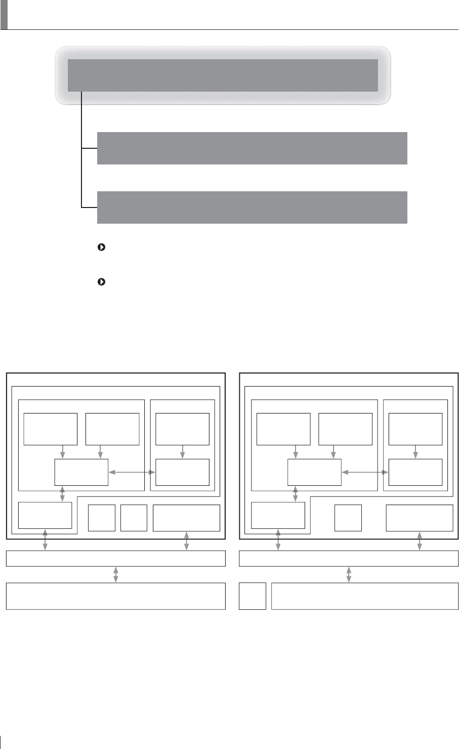
For the U.S. For other countries
DR-ID 600
DR-ID 600RU
DR-ID 600PU DR-ID 600PU
Image processing unit of other digital radiography system
DR-ID 300CL
Flat panel sensor
DR-ID 600SE or
DR-ID 601SE
Flat panel sensor
DR-ID 600SE or
DR-ID 601SE
Flat panel sensor
DR-ID 600SE or
DR-ID 601SE
Battery
charger
Access
point*
Power supply unit
DR-ID 600MP
Power supply unit
DR-ID 600MP
Control cabinet
DR-ID 600MC
Image processing unit
DR-ID 300CL
Hub
:LWKUHJDUGWRWKHDFFHVVSRLQWFRQVXOWRXURI¿FLDOGHDOHU
7KHFRQ¿JXUDWLRQRIWKHV\VWHPYDULHVGHSHQGLQJRQWKHFRXQWU\
7KHUHDUHWZRW\SHVRIÀDWSDQHOVHQVRUV'5,'6(ZLUHOHVVZLUHGFRPPXQLFDWLRQPRGHDQG
DR-ID 600SE (wired communication mode). Although the contents of this manual are described by
taking the example of DR-ID 601SE, the same can also be applied to DR-ID 600SE. With regard
WRWKHGHVFULSWLRQVSHFL¿FWR'5,'6(RU'5,'6(WKHSURGXFWQDPHLVVSHFL¿HGLQWKH
description.

v
FDR D-EVO Operation Manual 897N101473E
Contents at a Glance
Chapter 1
For Safe Operation
This chapter presents Warnings and Cautions we wish you to observe for safe
operation of the FDR D-EVO.
Chapter 2
6\VWHP&RQ¿JXUDWLRQ3URGXFW2YHUYLHZ
This chapter gives the various unit names and describes their functions and
features of the FDR D-EVO.
Chapter 3
Basic Operation
This chapter describes start-up, shut-down and other basic operations of the
FDR D-EVO.
Chapter 4
Troubleshooting
This chapter describes how to troubleshoot in the event of an error on the FDR
D-EVO, and provides explanations about a list of error messages each of which
appears when an error occurs.
Chapter 5
Daily Inspection and Maintenance
This chapter describes daily care and maintenance we wish you to perform so
that you can use the FDR D-EVO optimally.
Appendix
$SSHQGL[$ 6SHFL¿FDWLRQV
Appendix Z Precautions for Exposure
Appendix O Use of Optional Items
Maintenance and Inspection
vi FDR D-EVO Operation Manual 897N101473E
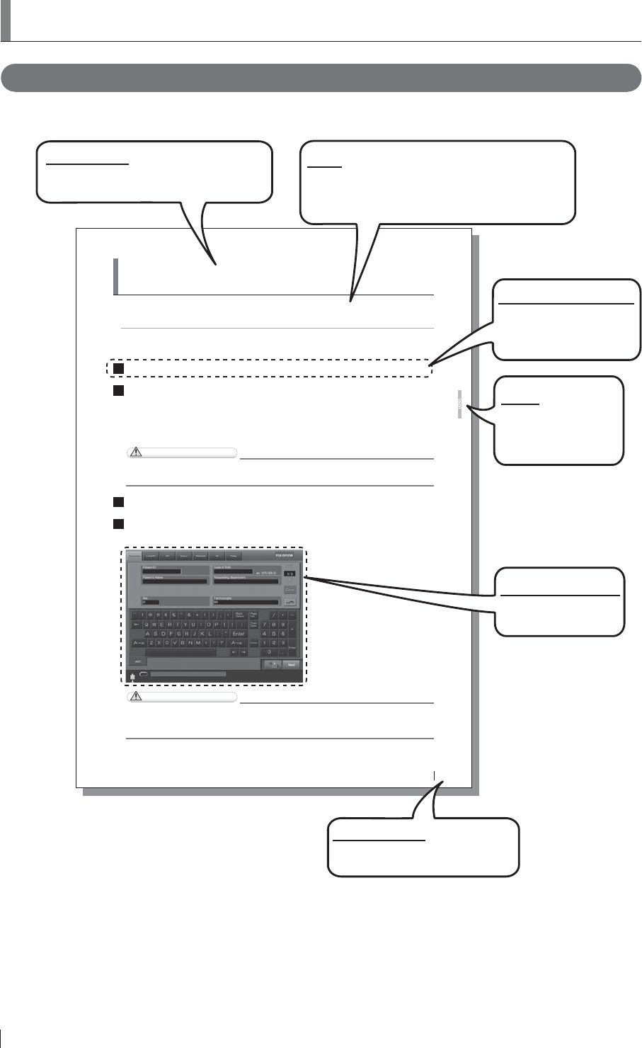
How to Read This Manual
%DVLFSDJHOD\RXW
3OHDVHKDYHDJRRGJUDVSRIWKHEDVLFSDJHFRQ¿JXUDWLRQRIWKLV2SHUDWLRQ0DQXDODVLOOXVWUDWHG
EHORZIRU\RXWRXVHLWPRUHHI¿FLHQWO\
3-7
FDR D-EVO Operation Manual 897N101473E
Basic Operation
3
3.2 Starting Up and Shutting Down the
System
This section explains how to start up and shut down the system. To start up the system, operations are
required on the FDR D-EVO main unit and on the Console.
To shut down the entire system, operations are required only on the Console.
3.2.1 Starting Up the System
1Press the ON side of the main switch of the power supply unit, if its power status LED is not lit.
2After FRQ¿UPLQJ the IROORZLQJ LWHPV SUHVV the power VZLWFK for the &RQVROH to VWDUW the
initialization process.
$OOFDEOHVVKRXOGEHFRQQHFWHGSURSHUO\
1RPHGLDVKRXOGEHLQVHUWHGLQWRWKH)''
7KHFRQWUROFDELQHWVWDUWVXSDXWRPDWLFDOO\
CAUTIONS
If the power status LED of the power supply unit does not come on after turning on the
&RQVROH turn on the control FDELQHW
3Turn on the radiographic examination stand.
4After displaying the start-up progression status, software version, and initialization progression
VWDWXV the DFWLYDWLRQ FRPSOHWLRQ VFUHHQ EHORZ ZLOO EH GLVSOD\HG on the &RQVROH
$FWLYDWLRQFRPSOHWLRQVFUHHQRIWKH&RQVROH
CAUTIONS
An error occurs if the system is started up immediately after shutdown.
To restart the system, make sure that the power status LED of the power supply unit is off, and
then SUHVV the power VZLWFK for the &RQVROH
3DJHQXPEHU
Displayed in conjunction with the
chapter number.
Section title
Shows the title of an operation procedure
described in the section.
Lead
Describes information we wish you to know in
advance of your operating the system or information
that may help you to operate it.
Displayed screen
A screen that appears
during operation.
Operation procedure
Describes an operation
procedure according to
sequential numbers.
Index
A caption that facilitates
you to open a desired
[Chapter] quickly.
vii
FDR D-EVO Operation Manual 897N101473E
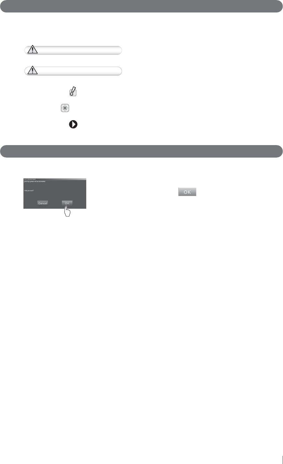
0DUNV
Information items to be observed when you are operating this system and the supplementary
remarks are described in this manual with the respective marks.
For the safe system operation, be sure to observe Warning/Caution.
WARNING Indicates hazardous situations that may lead to serious injuries or
even death if the precaution is not or cannot be followed.
CAUTIONS
Indicates hazardous situations that may lead to mild or moderate
injury or physical damages if the caution is not or cannot be
followed.
Indicates procedures requiring special attention, instructions that
must be followed, supplementary explanations, etc.
HINT Shows an item helpful for further effective system operation.
Shows a more detailed operation method or an item that
describes additional information.
Expressions
Messages appear on the display panel and the buttons are shown as below.
Ɣ %XWWRQVH[DPSOH
------------------------------ Select .
The button to operate is shown.

viii FDR D-EVO Operation Manual 897N101473E
Contents
Introduction ...........................................................................................................................iii
FDR D-EVO System Operation Manuals .............................................................................iv
Contents at a Glance ............................................................................................................ v
How to Read This Manual ....................................................................................................vi
Chapter 1 For Safe Operation
1.1 Precautions Before Operating This Equipment ....................................................... 1-1
1.2 Precautions to be Observed When Using the Electric Medical Equipment ............. 1-2
1.3 Safety ...................................................................................................................... 1-3
1.4 Electromagnetic Compatibility (EMC) ...................................................................... 1-8
1.4.1 DR-ID 600PU and DR-ID 300CL .............................................................................1-8
1.4.2 DR-ID 600MC ........................................................................................................1-13
1.5 Precautions in Using the FDR D-EVO ................................................................... 1-16
1.5.1 Handling .................................................................................................................1-16
1.5.2 Before Exposure ....................................................................................................1-17
1.5.3 During Exposure ....................................................................................................1-17
1.5.4 During Cleaning .....................................................................................................1-17
1.5.5 Storage ..................................................................................................................1-17
1.6 Locations of Labels and Signs .............................................................................. 1-18
1.6.1 Locations of Labels ................................................................................................1-18
1.6.2 DR-ID 600 ..............................................................................................................1-19
1.6.3 DR-ID 600PU .........................................................................................................1-20
1.6.4 Safety and Other Symbols .....................................................................................1-21
1.7 Installation Conditions ...........................................................................................1-22
1.7.1 Installation Space When Setting the Control Cabinet in the X-ray Room ..............1-22
Chapter 2
6\VWHP&RQ¿JXUDWLRQ3URGXFW2YHUYLHZ
2.1 FDR D-EVO ............................................................................................................. 2-1
6\VWHP&RQ¿JXUDWLRQ ..............................................................................................2-1
2.1.2 Features of the FDR D-EVO ....................................................................................2-2
2.2 Unit Names and the Functions ................................................................................ 2-3
2.2.1 DR-ID 600 ................................................................................................................2-3
&RQVROH'LVSOD\&RQ¿JXUDWLRQ ................................................................................ 2-5
2.4 Routine Operation Diagram..................................................................................... 2-6
Chapter 3 Basic Operation
3.1 Preparing the Flat Panel Sensor .............................................................................3-1
3.1.1 Type of Flat Panel Sensor .......................................................................................3-1
3.1.2 Number of the Connectable Flat Panel Sensors .....................................................3-1
3.1.3 Connecting/Disconnecting the Flat Panel Sensor (DR-ID 601SE) Connector.........3-1
3.1.4 Connecting/Disconnecting the Sensor Cable Relay Connector for the Flat Panel
Sensor (DR-ID 600SE) ............................................................................................3-2
3.1.5 Inserting/Removing the Flat Panel Sensor into/from the Radiographic Examination
Stand .......................................................................................................................3-3
3.1.6 Changing the Direction of the Flat Panel Sensor Connector ...................................3-4
3.1.7 Charging the Battery Pack (Optional) for the Flat Panel Sensor (DR-ID 601SE) ....3-5
3.1.8 Installing/Removing the Battery Pack (Optional) for the Flat Panel Sensor (DR-ID
601SE) ..................................................................................................................................3-6

ix
FDR D-EVO Operation Manual 897N101473E
3.2 Starting Up and Shutting Down the System ............................................................ 3-7
3.2.1 Starting Up the System ............................................................................................3-7
3.2.2 Shutting Down the System ......................................................................................3-8
3.3 Routine Operations ................................................................................................. 3-9
Step 1 Entering the Patient Information ............................................................................3-10
Step 2 Selecting the Anatomical Region and Exposure/Study Menu................................ 3-11
Step 3 X-ray Exposure ......................................................................................................3-13
[1] Positioning the patient ......................................................................................3-13
[2] X-ray exposure/Image displaying .....................................................................3-14
[3] For exposures of the next patient using the same menus ................................3-16
Chapter 4 TroubleshootinJ
4.1 When a Message Appears on the Console ............................................................. 4-1
[1] If a warning dialog box appears .........................................................................4-1
[2] If a communication error occurs between the Console and the connected DR
system ................................................................................................................4-1
[3] If an error occurs on the Console .......................................................................4-2
[4] If an error occurs on an output destination device ..............................................4-2
4.2 How to Cope with an Error... ................................................................................... 4-3
[1] When the system hangs up... .............................................................................4-3
[2] When the Console is turned off due to an electrical outage ...............................4-4
[3] If a hard disk of the Console is damaged ...........................................................4-4
[4] If a white image is displayed after an exposure ..................................................4-4
[5] Precautions for operating the system when “Initializing” or “Changing FPD” is
displayed in the Console’s operating status display at the time of replacing the
ÀDWSDQHOVHQVRU .................................................................................................4-4
>@,IZLUHOHVVFRPPXQLFDWLRQZLWKWKHÀDWSDQHOVHQVRU'5,'6(LVQRW
possible ...............................................................................................................4-4
>@,IZLUHOHVVFRPPXQLFDWLRQPRGHLVGLVDEOHGZKHQXVLQJWKHÀDWSDQHOVHQVRU
(DR-ID 601SE) ....................................................................................................4-4
Chapter 5 Daily Inspection and Maintenance
5.1 Daily User Inspection and Maintenance .................................................................. 5-1
5.1.1 Daily Inspection (DR-ID 600) ...................................................................................5-1
5.1.2 Periodical Inspection ................................................................................................5-2
5.1.3 Effective Period of Use ............................................................................................5-2
$SSHQGL[$6SHFL¿FDWLRQs
$ 6SHFL¿FDWLRQV ..........................................................................................................A-1
A.1.1 Processing Capacity (DR-ID 600) ........................................................................... A-1
A.1.2 Image Output (DR-ID 600) ...................................................................................... A-1
A.1.3 Reduced Equivalent (DR-ID 600) ........................................................................... A-3
A.1.4 Power Supply Conditions ........................................................................................ A-3
A.1.5 Environmental Conditions ....................................................................................... A-3
A.2 External View and Weight .......................................................................................A-4
A.2.1 DR-ID 600 ............................................................................................................... A-4
Appendix Z Precautions for Exposure
Z1. Precautions for Exposure in AUTO MODE ..............................................................Z-1
Z.1.1 Radiation Field .........................................................................................................Z-1
Z.1.2 Depiction of the Cervical Region .............................................................................Z-2
Z.1.3 Depiction of the HIP JOINT AXL – 2 Menu ..............................................................Z-2
Z.1.4 EDR Image Data Analysis .......................................................................................Z-3
Z.2 Precautions for Exposure in SEMI-AUTO MODE ...................................................Z-4

xFDR D-EVO Operation Manual 897N101473E
Z.3 Precautions for Exposure in SEMI-X MODE ...........................................................Z-5
Z.4 Precautions for Exposure in FIX MODE ..................................................................Z-6
Z.5 Other Precautions ...................................................................................................Z-7
Z.5.1 Precautions for Exposure of a Subject in Relatively Large Contrast .......................Z-7
Z.5.2 Precautions for DR System .....................................................................................Z-7
Z.5.3 Precautions for Assuring the Radiation Field ...........................................................Z-7
Z.5.4 Precautions Related to the X-ray Exposure Time ....................................................Z-7
Z.5.5 Images Output When the X-ray Shot Switch is Operated Incorrectly ......................Z-8
Z.5.6 Precautions for Urgent Use .....................................................................................Z-8
Z.5.7 Precautions Related to Continuous Operation ........................................................Z-8
Z.5.8 Precautions Related to Grid .....................................................................................Z-8
Appendix O Use of Optional Items
O.1 Optional Items ....................................................................................................... O-1
O.2 Using the Remote Switch ....................................................................................... O-2
O.2.1 Remote Switch ........................................................................................................ O-2
O.2.2 Relay Cable ............................................................................................................O-2
O.3 Using the SE Storage Case ................................................................................... O-3
O.4 Using the DAP Connector Cable ............................................................................ O-4
O.5 Using the Retaining Bracket for MP ....................................................................... O-5
Maintenance and Inspection

1-1
FDR D-EVO Operation Manual 897N101473E
For Safe Operation
1
Chapter 1 For Safe Operation
3UHFDXWLRQV%HIRUH2SHUDWLQJ7KLV
(TXLSPHQW
Before using this equipment, please read “Precautions Before Operating This Equipment” carefully so
that you can operate it correctly.
Whenever you operate this equipment, be sure to observe those precautions. Failure to do so may
cause you to subject to injuries or property damage to occur.
The institution where the equipment is installed is responsible for its use and
maintenance.
In addition, this equipment should not be used by persons other than doctors or
suitably trained staff.
7KLVV\VWHPLVFODVVL¿HGDVDPHGLFDOGHYLFHXQGHU(&'LUHFWLYH((&
This equipment has been designed on the assumption that the patient would not
come into direct contact with it or for operation by appropriately trained operator.
Process waste correctly, as stipulated by local law or any regulations that apply.
Part of the components contains harmful substances which may pollute the ambient
environment if disposed carelessly. For details on product disposal, contact a
FUJIFILM dealer.

1-2 FDR D-EVO Operation Manual 897N101473E
For Safe Operation
1
1.2 Precautions to be Observed When
8VLQJWKH(OHFWULF0HGLFDO(TXLSPHQW
We ask that you observe these usage precautions and use the equipment correctly.
1. This equipment should be used only by people who have the proper skills.
2. Observe the following precautions when installing the equipment.
2-1. Install the equipment where water will not splash it.
2-2. Install the equipment where it will not be adversely affected by air pressure, temperature,
humidity, ventilation, sunlight, dust or the presence of salt, sulfur or like substances in the
atmosphere.
2-3. Make sure the equipment will remain in stable condition on a level surface and not be
subjected to vibration or shock.
2-4. Do not install the equipment in places where chemicals are stored or gases emitted.
2-5. Make sure that the power frequency, voltage and power consumption are appropriate.
2-6. Connect the ground wire correctly.
3. Observe the following precautions before beginning to use the device.
&RQ¿UPWKDWWKHJURXQGZLUHKDVEHHQFRPSOHWHO\FRQQHFWHG
3-2. Make sure that all cords have been connected properly and safely.
3-3. Be aware that correct diagnosis can be hindered and danger can result from using different
pieces of equipment together.
3-4. Make sure that the battery and power supply are installed properly.
4. Observe the following precautions when using the equipment.
4-1. Make sure not to exceed the time and dose required for diagnosis.
4-2. Always monitor the patient and the equipment for abnormalities.
4-3. Take an appropriate action, such as stopping the equipment after ensuring the patient’s
safety, if any abnormalities are found in his/her health or in the equipment.
5. Observe the following precautions after using the equipment.
5-1. Using the established procedure, then turn the power off.
5-2. When unplugging cords, do not pull on the body of the cord itself or apply unnecessary
force.
5-3. Observe the following precautions when storing the equipment.
I Store the equipment where water will not splash it.
II Store the equipment where it will not be adversely affected by air pressure, temperature,
humidity, ventilation, sunlight, dust or the presence of salt, sulfur or like substances in
the atmosphere.
III Make sure the equipment will remain in stable condition on a level surface and not be
subjected to vibration or shock.
IV Do not store the equipment in places where chemicals are stored or gases emitted.
5-4. After using the accessories, recollect them and put them back in order.
5-5. Make sure to clean the equipment for the next use.
,IWKHUHLVWURXEOHZLWKWKHHTXLSPHQWGRQRWDWWHPSWWR¿[LWUDQGRPO\,QVWHDGGRZKDWLV
indicated and entrust repairs to a professional.
7. Do not remodel the equipment.
8. Maintenance and Inspection
8-1. Make inspect the equipment and parts periodically.
8-2. If the equipment has not been used for a long time, make sure that it operates normally and
safely prior to using it again.
9. Other Items
9-1. When subjecting patients (particularly infants and pregnant women) to radiation, make sure
not to exceed the necessary time and dose. Also, ensure that radiation is contained within
WKHH[SRVXUHSODQHRIWKHÀDWSDQHOVHQVRU
9-2. Follow the Operation Manual and operate the equipment correctly.

1-3
FDR D-EVO Operation Manual 897N101473E
For Safe Operation
1
1.3 Safety
Before using the FDR D-EVO, read this section thoroughly to ensure that you use the product properly.
(OHFWULF6KRFN:DUQLQJVDQG&DXWLRQV
WARNING
The power supply to the FDR D-EVO is AC100 to 240V.
7RDYRLGHOHFWULFVKRFNVXVHUVVKRXOGDOZD\VWDNHWKHIROORZLQJSUHFDXWLRQV
Ɣ 1HYHURSHQDQ\FRYHUVRIWKHHTXLSPHQW
Ɣ ,QVWDOOWKHHTXLSPHQWLQDORFDWLRQZKHUHLWZLOOQRWEHH[SRVHGWRZDWHU
Ɣ &KHFNWKDWWKHHTXLSPHQWLVVHFXUHO\HDUWKHG
Ɣ &KHFNWKDWDOORIWKHFRUGVDQGFDEOHVDUHFRPSOHWHO\DQGVHFXUHO\FRQQHFWHG
Ɣ .HHSWKHLPDJHSURFHVVLQJXQLWDQGWKHFRQWUROFDELQHWRXWRIUHDFKRISDWLHQWV
WARNING
'RQRWWRXFKWKHSDWLHQW¶VERG\ZKLOHWRXFKLQJWKHFRQWUROFDELQHW2WKHUZLVHWKHSDWLHQWPD\
UHFHLYHDQHOHFWULFVKRFN
WARNING
'RQRWXVHDPXOWLSOHWDSFRQQHFWRURUH[WHQVLRQFDEOHIRUSRZHULQJWKHGHYLFHVFRQVWLWXWLQJ
WKHV\VWHP2WKHUZLVH¿UHRUHOHFWULFVKRFNPD\RFFXUGXHWRWKHHOHFWULFDOORDGH[FHHGLQJWKH
allowable limit.
WARNING
2EVHUYHWKHIROORZLQJSUHFDXWLRQVZKHQXVLQJWKHFDEOHV
Ɣ 7XUQRIIHDFKXQLWEHIRUHFRQQHFWLQJGLVFRQQHFWLQJWKHFDEOH
'RQRWWRXFKWKHSOXJDQGFRQQHFWRUZLWKZHWKDQGV2WKHUZLVHHOHFWULFVKRFNPD\UHVXOW
FDXVLQJGHDWKRUVHYHUHLQMXU\
Ɣ +ROGWKHSOXJRUFRQQHFWRUZKHQUHPRYLQJWKHFDEOH
3XOOLQJWKHFDEOHRUFDUU\LQJE\KROGLQJLWPD\GDPDJHWKHFDEOHFDXVLQJ¿UHRUHOHFWULF
VKRFN
Ɣ 'RQRWGDPDJHRUUHPRGHOWKHFDEOH
'RQRWSODFHDKHDY\REMHFWRQWKHFDEOHRUOD\LWXQGHUWKHÀDWSDQHOVHQVRU'RQRWVWHSRQ
SXOOIRUFLEO\EHQGRUEXQGOHWKHFDEOH2WKHUZLVH¿UHRUHOHFWULFVKRFNPD\UHVXOW
Ɣ 'RQRWXVHWKHÀDWSDQHOVHQVRUIRUWKHUDGLRJUDSKLFH[DPLQDWLRQVWDQGLILWVFDEOHEHFRPHV
RYHUORDGHG2WKHUZLVHWKHFDEOHPD\EHGDPDJHGFDXVLQJ¿UHRUHOHFWULFVKRFN
WARNING
'RQRWWXUQRQWKHV\VWHPZLWKGHZFRQGHQVDWLRQRQWKHÀDWSDQHOVHQVRU2WKHUZLVH¿UHRU
HOHFWULFVKRFNPD\UHVXOW
WARNING
'RQRWXVHWKHHTXLSPHQWLQDORFDWLRQZKHUHPHWDOSDUWLFOHVFRXOGFRPHLQWRWKHHTXLSPHQW
7KLVPD\FDXVHDQHOHFWULFVKRFN
1-4 FDR D-EVO Operation Manual 897N101473E
For Safe Operation
1
WARNING
'RQRWGLVDVVHPEOHRUUHPRGHOWKHHTXLSPHQW2WKHUZLVH¿UHRUHOHFWULFVKRFNPD\UHVXOW
.HHSDZD\IURPWKHSDUWVLQVLGHWKHSURGXFWZKLFKPD\FDXVHHOHFWULFVKRFN,I\RXWRXFK
them accidentally, death or severe injury may result.
WARNING
'RQRWKLWRUGURSWKHHTXLSPHQWRUVXEMHFWLWWRVHYHUHVKRFN2WKHUZLVHWKHHTXLSPHQWPD\
EHGDPDJHG,IWKHGDPDJHGHTXLSPHQWLVXVHG¿UHRUHOHFWULFVKRFNPD\UHVXOW
WARNING
%HIRUHXVLQJWKHÀDWSDQHOVHQVRU'5,'6(PDNHVXUHWKDWWKHEDWWHU\FRYHURUEDWWHU\
SDFNLVDWWDFKHG,IQRWDWWDFKHGDQHOHFWULFVKRFNPD\UHVXOW
CAUTIONS
$VWKHFDEOHVRIWKHHTXLSPHQWDUHORQJEHFDUHIXOQRWWRHQWDQJOHWKHFDEOHVGXULQJXVH
Also, be careful not to trip over the cables. Falls could result in injury.
CAUTIONS
)ROORZWKHVSHFL¿HGSURFHGXUHZKHQWXUQLQJRIIWKHHTXLSPHQW2WKHUZLVHWKHÀDWSDQHO
VHQVRUFRXOGEHGDPDJHGE\WKHUPDOVKRFN
CAUTIONS
'RQRWVWRUHPDJQHWLFPHGLDQHDUWKH'5V\VWHPDQGFRQWUROFDELQHW2WKHUZLVHPDJQHWLVP
JHQHUDWHGE\WKHHTXLSPHQWPD\FDXVHWKHGDWDWREHORVW
CAUTIONS
.HHSWKHHTXLSPHQWDZD\IURPSDWLHQW¶VERG\ÀXLGVFKHPLFDOVZDWHUHWF
2WKHUZLVHLWPD\EHFRPHGDPDJHGFDXVLQJ¿UHRUHOHFWULFVKRFN
,IQHFHVVDU\SURWHFWWKHÀDWSDQHOVHQVRUE\FRYHULQJLWZLWKDGLVSRVDEOHEDJ
([SORVLRQ:DUQLQJV
WARNING
%HFDXVHWKLVHTXLSPHQWLVQRWH[SORVLRQSURRIGRQRWXVHFRPEXVWLEOHDQGH[SORVLYHJDVHV
QHDUWKHHTXLSPHQW
WARNING
)ODPPDEOHJDVVHVPD\VWD\LQWKHURRPDIWHUGLVLQIHFWLRQ9HQWLODWHWKHURRPZHOOEHIRUH
SRZHULQJRQWKHV\VWHPIROORZLQJGLVLQIHFWLRQ

1-5
FDR D-EVO Operation Manual 897N101473E
For Safe Operation
1
:DUQLQJVIRU$EQRUPDOLWLHV
WARNING
,IDQ\RIWKHIROORZLQJRFFXUVLPPHGLDWHO\WXUQRIIWKHSRZHURIHDFKXQLWXQSOXJWKHSRZHU
cable from the outlet, and then contact a FUJIFILM dealer.
Ɣ :KHQVPRNHVWUDQJHRGRURUDEQRUPDOVRXQGLVSUHVHQW
Ɣ :KHQDIRUHLJQREMHFWVXFKDVDPHWDOREMHFWRUOLTXLGHQWHUVWKHSURGXFW
Ɣ :KHQWKHHTXLSPHQWLVGURSSHGRUKLWDQGLVGDPDJHG
Installation Precautions
CAUTIONS
'RQRWLQVWDOOWKHV\VWHPLQDORFDWLRQZLWKWKHIROORZLQJFRQGLWLRQV
Ɣ :KHUHWKHWHPSHUDWXUHFKDQJHVVKDUSO\
Ɣ &ORVHWRKHDWVRXUFHVVXFKDVDKHDWHU
Ɣ :KHUHWKHV\VWHPPD\EHH[SRVHGWRZDWHUGXHWRZDWHUOHDNDJHRULQJUHVV
Ɣ :KHUHFRUURVLYHJDVPD\EHJHQHUDWHG
Ɣ :KHUHWKHUHLVH[FHVVLYHGXVW
Ɣ :KHUHWKHV\VWHPLVVXEMHFWWRIUHTXHQWRUH[FHVVLYHYLEUDWLRQVKRFN
Ɣ :KHUHWKHV\VWHPLVH[SRVHGWRGLUHFWVXQOLJKW
Ɣ :KHUHWKHUHLVQRYHQWLODWRU
CAUTIONS
)RUYHWHULQDU\RUPRELOHDSSOLFDWLRQVSOHDVHFRQWDFWDFHUWL¿HG)8-,),/0VHUYLFH
representative.
CAUTIONS
Use the system indoor in wireless communication mode. For details, contact a FUJIFILM
dealer.
Connection Instructions
WARNING
0DNHVXUHWKDWWKHGHYLFHVWREHFRQQHFWHGWRWKHHTXLSPHQWDUHDXWKRUL]HGIRUFRQQHFWLRQ
System Isolation Instructions
WARNING
To ensure complete system isolation, never install any unauthorized accessories or other such
items.
When it is necessary to install authorized accessories or optional items, contact a FUJIFILM
dealer.
1-6 FDR D-EVO Operation Manual 897N101473E
For Safe Operation
1
WARNING
.HHSHTXLSPHQWRWKHUWKDQWKRVHXVHGIRUSDWLHQWVRXWRIWKHLUUHDFKWRHQVXUHDSSURSULDWH
system isolation.
WARNING
Do not move the Console from where it is installed.
Software Precautions
CAUTIONS
Do not install additional software to the system. Do not uninstall any of the software
preinstalled in the system.
The system is preinstalled with the appropriate software. If other software is installed or if the
H[LVWLQJVRIWZDUHLVXQLQVWDOOHGYDULRXVRSHUDWLRQDOHUURUVPD\UHVXOW
Disinfection Instructions
WARNING
&RQ¿UPWKDWWKHUHVSLUDWRU\GHQVLW\RIGLVLQIHFWDQWLQFOXGLQJVROYHQWLVXQGHUOHJDOUHJXODWLRQ
&HUWDLQGLVLQIHFWDQWVPD\GDPDJHKHDOWK:KHQXVLQJDGLVLQIHFWDQWIROORZLQVWUXFWLRQV
supplied by the manufacturers.
WARNING
'RQRWXVHWKHIROORZLQJGLVLQIHFWDQWVRUVWHULOL]HUVDWWKHWLPHRIGLVLQIHFWLRQ4XDOLW\
SHUIRUPDQFHDQGVDIHW\RIWKHHTXLSPHQWFDQQRWEHDVVXUHG
Ɣ &KORULFGLVLQIHFWDQWZKLFKLVVWURQJO\FRUURVLYHWRPHWDOVDQGUXEEHUSDUWV
Ɣ 'LVLQIHFWDQWZKRVHXVHVRQPHWDOVSODVWLFVDQGFRDWLQJDUHIRUELGGHQDFFRUGLQJWRWKH
instructions supplied with the disinfectant.
Ɣ )RUPDOLQJDVDQGGLVLQIHFWDQWVSUD\VWKDWPD\JHWLQVLGHWKHHTXLSPHQW
Ɣ 8OWUDYLROHWVWHULOL]HUV
Disinfectant ethanol is recommended for disinfection. Carefully read the instructions and
cautions supplied with the disinfectant before use.
CAUTIONS
&OHDQWKHVHQVRUXQLWRIWKHÀDWSDQHOVHQVRUZLWKHWKDQROIRUGLVLQIHFWLRQHWFIRUHDFKSDWLHQW
to prevent infection.

1-7
FDR D-EVO Operation Manual 897N101473E
For Safe Operation
1
3UHFDXWLRQVIRU&KDUJLQJWKH%DWWHU\
CAUTIONS
2EVHUYHWKHIROORZLQJSUHFDXWLRQVZKHQFKDUJLQJWKHEDWWHU\SDFNRSWLRQDOXVLQJWKHEDWWHU\
FKDUJHURSWLRQDO
Ɣ 'RQRWXVHWKHEDWWHU\SDFN1RUEDWWHU\FKDUJHULQFRPELQDWLRQZLWKDQ\EDWWHU\
SDFNRUEDWWHU\FKDUJHULQFOXGLQJWKH$&DGDSWHURWKHUWKDQWKRVHUHFRPPHQGHGE\
FUJIFILM Corporation.
Ɣ 'RQRWGLVDVVHPEOHRUFRQYHUWWKHEDWWHU\SDFNRUEDWWHU\FKDUJHU
Ɣ ,IWKHEDWWHU\SDFNRUEDWWHU\FKDUJHUEHFRPHVIDXOW\FRQVXOWRXURI¿FLDOGHDOHU
Ɣ 'RQRWFRYHUWKHKROHVLQWKHEDWWHU\FKDUJHUZLWKIRUHLJQPDWWHU
Ɣ $YRLGWKHDFFXPXODWLRQRIGXVWRQWKHEDWWHU\FKDUJHU
Ɣ ,QVHUWWKHEDWWHU\SDFNLQWRWKHEDWWHU\FKDUJHUVHFXUHO\
Ɣ ,IWKHLQVHUWLRQGLUHFWLRQRUSRVLWLRQRIWKHEDWWHU\SDFNLVLQFRUUHFWWKHEDWWHU\LVQRW
FKDUJHGSURSHUO\
Ɣ :KHQLQVHUWLQJWKHEDWWHU\SDFNSUHYHQWIRUHLJQPDWWHUIURPJHWWLQJLQWRWKHEDWWHU\
FKDUJHU
Ɣ :KLOHFKDUJLQJWKHEDWWHU\GRQRWDOORZWKHEDWWHU\SDFNRUEDWWHU\FKDUJHUJHWZHWRUGXVW\
Ɣ 'RQRWVWHSRQWKH$&DGDSWHURIWKHEDWWHU\FKDUJHU$OVREHFDUHIXOQRWWRWULSRYHUWKH
power cable.
Ɣ 'RQRWVXEMHFWWKHEDWWHU\DQGEDWWHU\FKDUJHUWRVHYHUHVKRFNE\GURSSLQJWKHPHWF
%DWWHU\3DFN2SWLRQDO3UHFDXWLRQV
CAUTIONS
2EVHUYHWKHIROORZLQJSUHFDXWLRQVZKHQXVLQJWKHEDWWHU\SDFNRSWLRQDO
Ɣ :KHQVWRULQJWKHEDWWHU\SDFNIRUDORQJSHULRGFKDUJHWKHEDWWHU\IXOO\UHPRYHLWIURP
WKHÀDWSDQHOVHQVRUDQGWKHQVWRUHLWLQDFRRODQGGDUNSODFH5HFKDUJHWKHVWRUHGEDWWHU\
every six months or every year. Otherwise a decrease in battery capacity or other problems
may result.
Ɣ 'RQRWOHDYHWKHUHPRYHGEDWWHU\SDFNLQWKHFDURURWKHUSODFHVH[SRVHGWRKLJK
WHPSHUDWXUH7KHEDWWHU\SDFNPD\LJQLWHUHVXOWLQJLQ¿UH
Ɣ :KHQGLVSRVLQJRIWKHEDWWHU\SDFNFRQVXOWRXURI¿FLDOGHDOHU
Other Cautions
CAUTIONS
Install the system in accordance with what is provided by IEC60601-1-1. Contact a FUJIFILM
GHDOHUIRULQVWDOODWLRQDQGUHORFDWLRQH[FHSWWKHÀDWSDQHOVHQVRURIWKHV\VWHP
CAUTIONS
'RQRWKLWRUGURSWKHHTXLSPHQW2WKHUZLVHLQMXU\RUGDPDJHWRLPDJHVHWFPD\UHVXOW
CAUTIONS
Be sure to inspect the system periodically.
7RDVVXUHRSWLPXPSHUIRUPDQFHRIWKHHTXLSPHQWLWLVQHFHVVDU\WRV\VWHPDWLFDOO\SHUIRUP
maintenance and inspection. For information on maintenance and inspection, contact a
FUJIFILM dealer.

1-8 FDR D-EVO Operation Manual 897N101473E
For Safe Operation
1
(OHFWURPDJQHWLF&RPSDWLELOLW\(0&
1.4.1 DR-ID 600PU and DR-ID 300CL
This equipment has been tested and found to comply with the limits for medical devices to the IEC
$(1$0HGLFDO'HYLFH'LUHFWLYH((&
These limits are designed to provide reasonable protection against harmful interference in a typical
medical installation.
This equipment generates, uses and can radiate radio frequency energy and, if not installed and
used in accordance with the instructions, may cause harmful interference to other devices in the
vicinity.
However, there is no guarantee that interference will not occur in a particular installation.
If this equipment does cause harmful interference to other devices, which can be determined by
tuning the equipment off and on, the user is encouraged to try to correct the interference by one or
PRUHRIWKHIROORZLQJPHDVXUHV
5HRULHQWRUUHORFDWHWKHUHFHLYLQJGHYLFH
,QFUHDVHWKHVHSDUDWLRQEHWZHHQWKHHTXLSPHQW
&RQQHFWWKHHTXLSPHQWLQWRDQRXWOHWRQDFLUFXLWGLIIHUHQWIURPWKDWWRZKLFKWKHRWKHUGHYLFHV
are connected.
If the problem cannot be solved with the above measures, stop using this equipment and consult
WKHPDQXIDFWXUHURURXURI¿FLDOGHDOHUIRUKHOS
WARNING
Ɣ 'RQRWSODFHGHYLFHVJHQHUDWLQJHOHFWURPDJQHWLFZDYHQHDUWKLVHTXLSPHQW
Ɣ ,IDGHYLFHVRWKHUWKDQWKRVHVSHFL¿HGLVFRQQHFWHGSUHGHWHUPLQHG(0&SHUIRUPDQFH
FDQQRWEHJXDUDQWHHG

1-9
FDR D-EVO Operation Manual 897N101473E
For Safe Operation
1
Further information for IEC 60601-1-2 (EN60601-1-2)
1. Medical electrical equipment needs special precautions regarding EMC and needs to be installed
and put into service according to the EMC information provided in the accompanying documents.
2. Portable and mobile RF communications equipment can affect medical electrical equipment.
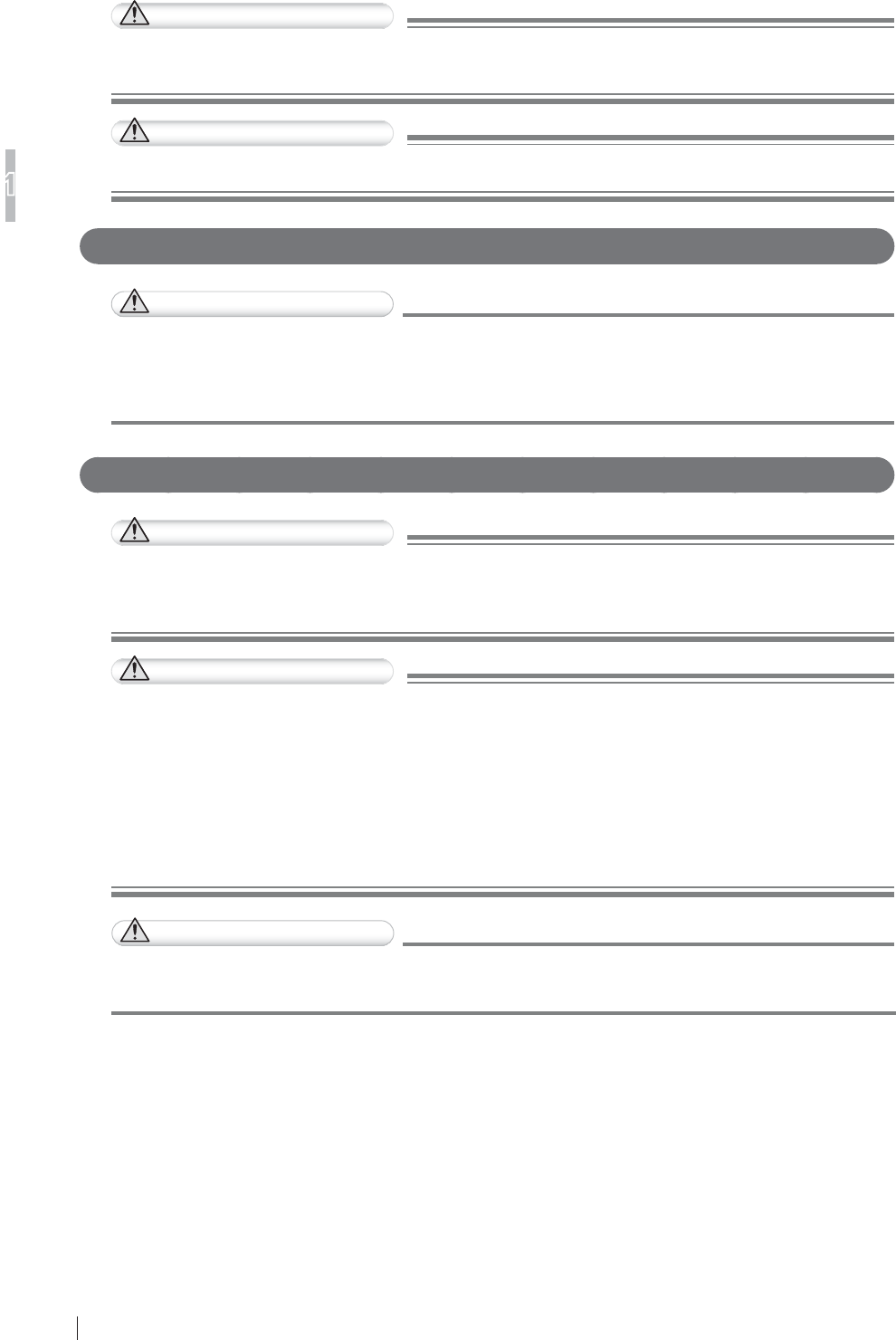
3. Information regarding the cable affecting EMC is as follows.
Name Connected Device 0D[LPXP/HQJWK *HQHUDO6SHFL¿FDWLRQ
Network Cable Between the DR-ID 600PU
and the DR-ID 600MC
30m Cat5e or more,
UTP type and straight cable
Between the DR-ID 600MC
and the DR-ID 300CL
100m
Power Cable DR-ID 600PU 3m Use a hospital grade power cable.
(for North America)
A non-hospital grade power cable
can be used. (for other countries)
DR-ID 300CL Depends on the cable length of a personal computer.
4.
7KHXVHRIDFFHVVRULHVWUDQVGXFHUVDQGFDEOHVRWKHUWKDQWKRVHVSHFL¿HGZLWKWKHH[FHSWLRQRI
transducers and cables sold by FUJIFILM Corporation as replacement parts for internal components,
may result in increased emissions or decreased immunity of the DR-ID 600PU and the DR-ID 300CL.
5. The DR-ID 600PU and the DR-ID 300CL should not be used adjacent to or stacked with other
equipment.
If adjacent or stacked use is necessary, the DR-ID 600PU and the DR-ID 300CL should be
REVHUYHGWRYHULI\QRUPDORSHUDWLRQLQWKHFRQ¿JXUDWLRQLQZKLFKLWZLOOEHXVHG
6. Basic performance of the equipment and the system
After image data are acquired from the DR-ID 600PU, data correction is performed by the control cabinet
(DR-ID 600MC), and the image is saved in and displayed on the image processing unit (DR-ID 300CL).
7. Test items (Tables 1 to 4)
Table 1
*XLGDQFHDQGPDQXIDFWXUHU¶VGHFODUDWLRQHOHFWURPDJQHWLFHPLVVLRQV
7KH'5,'38DQGWKH'5,'&/DUHLQWHQGHGIRUXVHLQWKHHOHFWURPDJQHWLFHQYLURQPHQWVSHFL¿HGEHORZ
The customer or the user of the DR-ID 600PU and the DR-ID 300CL should assure that they are used in such an
environment.
Emissions test Compliance (OHFWURPDJQHWLFHQYLURQPHQWJXLGDQFH
RF emissions
CISPR 11 Group 1
The DR-ID 600PU and the DR-ID 300CL use RF energy
only for their internal function.
Therefore, their RF emissions are very low and are not
likely to cause any interference in nearby electronic
equipment.
RF emissions
CISPR 11 Class A
The DR-ID 600PU and the DR-ID 300CL are suitable
for use in all establishments other than domestic and
those directly connected to the public low-voltage power
supply network that supplies buildings used for domestic
purposes.
Harmonic emissions
IEC61000-3-2 Complies
'5,'38&ODVV$
'5,'&/&ODVV'
9ROWDJHÀXFWXDWLRQV
ÀLFNHUHPLVVLRQV
IEC61000-3-3
Complies

1-10 FDR D-EVO Operation Manual 897N101473E
For Safe Operation
1
Table 2
*XLGDQFHDQGPDQXIDFWXUHU¶VGHFODUDWLRQHOHFWURPDJQHWLFLPPXQLW\
7KH'5,'38DQGWKH'5,'&/DUHLQWHQGHGIRUXVHLQWKHHOHFWURPDJQHWLFHQYLURQPHQWVSHFL¿HGEHORZ
The customer or the user of the DR-ID 600PU and the DR-ID 300CL should assure that they are used in such an
environment.
Immunity test IEC 60601 test level Compliance level (OHFWURPDJQHWLFHQYLURQPHQW
JXLGDQFH
Electrostatic
discharge
(ESD)
IEC61000-4-2
±6kV contact
±8kV air
±6kV contact
±8kV air
Floors should be wood, concrete or
FHUDPLFWLOH,IÀRRUVDUHFRYHUHGZLWK
synthetic material, the relative humidity
should be at least 30%.
Electrical fast
transient/burst
IEC61000-4-4
±2kV for power supply
lines
±1kV for input/output
lines
±2kV for power supply
lines
±1kV for input/output
lines
Mains power quality should be that
of a typical commercial or hospital
environment.
Surge
IEC61000-4-5
±1kV differential mode
±2kV common mode
±1kV differential mode
±2kV common mode
Mains power quality should be that
of a typical commercial or hospital
environment.
Voltage dips, short
interruptions and
voltage variations on
power supply input
lines
IEC61000-4-11
<5% UT
(>95% dip in UT)
for 0.5 cycle
40% UT
(60% dip in UT)
for 5 cycles
70% UT
(30% dip in UT)
for 25 cycles
<5% UT
(>95% dip in UT)
for 5 s
<5% UT
(>95% dip in UT)
for 0.5 cycle
40% UT
(60% dip in UT)
for 5 cycles
70% UT
(30% dip in UT)
for 25 cycles
<5% UT
(>95% dip in UT)
for 5 s
Mains power quality should be that
of a typical commercial or hospital
environment. If the user of the DR-ID
600PU and the DR-ID 300CL requires
continued operation during power mains
interruptions, it is recommended that the
DR-ID 600PU and the DR-ID 300CL be
powered from an uninterruptible power
supply or a battery.
Power frequency
(50/60Hz) magnetic
¿HOG
IEC61000-4-8
3 A/m 3 A/m
3RZHUIUHTXHQF\PDJQHWLF¿HOGVVKRXOG
be at levels characteristic of a typical
location in a typical commercial or
hospital environment.
127(UT is the a.c. mains voltage prior to application of the test level.
1-11
FDR D-EVO Operation Manual 897N101473E
For Safe Operation
1
Table 3
*XLGDQFHDQGPDQXIDFWXUHU¶VGHFODUDWLRQHOHFWURPDJQHWLFLPPXQLW\
7KH'5,'38DQGWKH'5,'&/DUHLQWHQGHGIRUXVHLQWKHHOHFWURPDJQHWLFHQYLURQPHQWVSHFL¿HGEHORZ
The customer or the user of the DR-ID 600PU and the DR-ID 300CL should assure that they are used in such an
environment.
Immunity test IEC 60601 test level Compliance level (OHFWURPDJQHWLFHQYLURQPHQWJXLGDQFH
Conducted RF
IEC61000-4-6
Radiated RF
IEC61000-4-3
3 Vrms
150 kHz to 80 MHz
3 V/m
80 MHz to 2.5 GHz
3 Vrms
3 V/m
Portable and mobile RF communications equipment
should be used no closer to any part of the DR-ID
600PU and the DR-ID 300CL, including cables,
than the recommended separation distance
calculated from the equation applicable to the
frequency of the transmitter.
Recommended separation distance
d = 1.2
d = 1.2 80 MHz to 800 MHz
d = 2.3 800 MHz to 2.5 GHz
where
P
is the maximum output power rating of the
transmitter in watts (W) according to the transmitter
manufacturer and
d
is the recommended separation
distance in metres (m).
)LHOGVWUHQJWKVIURP¿[HG5)WUDQVPLWWHUVDV
determined by an electromagnetic site survey,a
should be less than the compliance level in each
frequency range.b
Interference may occur in the vicinity of equipment
PDUNHGZLWKWKHIROORZLQJV\PERO
127($W0+]DQG0+]WKHKLJKHUIUHTXHQF\UDQJHDSSOLHV
127(7KHVHJXLGHOLQHVPD\QRWDSSO\LQDOOVLWXDWLRQV(OHFWURPDJQHWLFSURSDJDWLRQLVDIIHFWHGE\DEVRUSWLRQDQG
UHÀHFWLRQIURPVWUXFWXUHVREMHFWVDQGSHRSOH
D )LHOGVWUHQJWKIURP¿[HGWUDQVPLWWHUVVXFKDVEDVHVWDWLRQVIRUUDGLRFHOOXODUFRUGOHVVWHOHSKRQHVDQGODQG
mobile radios, amateur radio, AM and FM radio broadcast and TV broadcast cannot be predicted theoretically with
DFFXUDF\7RDVVHVVWKHHOHFWURPDJQHWLFHQYLURQPHQWGXHWR¿[HG5)WUDQVPLWWHUVDQHOHFWURPDJQHWLFVLWHVXUYH\
VKRXOGEHFRQVLGHUHG,IWKHPHDVXUHG¿HOGVWUHQJWKLQWKHORFDWLRQLQZKLFKWKH'5,'38DQGWKH'5,'&/
are used exceeds the applicable RF compliance, the DR-ID 600PU and the DR-ID 300CL should be observed to
verify normal operation. If abnormal performance is observed, additional measures may be necessary, such as
reorienting or relocating the DR-ID 600PU and the DR-ID 300CL.
E 2YHUWKHIUHTXHQF\UDQJHN+]WR0+]¿HOGVWUHQJWKVKRXOGEHOHVVWKDQ9P

1-12 FDR D-EVO Operation Manual 897N101473E
For Safe Operation
1
Table 4
Recommended separation distances between
3RUWDEOHDQGPRELOH5)FRPPXQLFDWLRQVHTXLSPHQWDQGWKH'5,'38DQGWKH'5,'&/
The DR-ID 600PU and the DR-ID 300CL are intended for use in the electromagnetic environment in which radiated RF
disturbances are controlled.
The customer or the user of the DR-ID 600PU and the DR-ID 300CL can help prevent electromagnetic interference
by maintaining a minimum distance between portable and mobile RF communications equipment (transmitters) and
the DR-ID 600PU and the DR-ID 300CL as recommended below, according to the maximum output power of the
communications equipment.
Rated maximum output
power of transmitter
W
6HSDUDWLRQGLVWDQFHDFFRUGLQJWRIUHTXHQF\RIWUDQVPLWWHU
m
150 kHz to 80 MHz
d = 1.2
80 MHz to 800 MHz
d = 1.2
800 MHz to 2.5 GHz
d = 2.3
0.01 0.12 0.12 0.23
0.1 0.38 0.38 0.73
1 1.2 1.2 2.3
10 3.8 3.8 7.3
100 12 12 23
For transmitters rated at a maximum output power not listed above, the recommended separation distance
d
in metres
(m) can be estimated using the equation applicable to the frequency of the transmitter, where
P
is the maximum output
power rating of the transmitter in watts (W) according to the transmitter manufacturer.
127( $W0+]DQG0+]WKHVHSDUDWLRQGLVWDQFHIRUWKHKLJKHUIUHTXHQF\UDQJHDSSOLHV
127( 7KHVHJXLGHOLQHVPD\QRWDSSO\LQDOOVLWXDWLRQV
(OHFWURPDJQHWLFSURSDJDWLRQLVDIIHFWHGE\DEVRUSWLRQDQGUHÀHFWLRQIURPVWUXFWXUHVREMHFWVDQGSHRSOH

1-13
FDR D-EVO Operation Manual 897N101473E
For Safe Operation
1
1.4.2 DR-ID 600MC
This equipment has been tested and found to comply with the international standard for medical
GHYLFHVEHORZDFFRUGLQJWRWKHUHTXLUHPHQWRIWKH,(&$(1
$
(0&6WDQGDUG&,635(1
&,635(1
(1,(&
(1,(&
This does not guarantee that there is no harmful electromagnetic interference under any installation
environment.
This equipment can generate, use and radiate radio frequency energy. If the equipment is not
installed and used in accordance with the instructions, or if peripheral devices that are not complied
with the EMC standard, harmful interference may be generated under a particular environment
causing malfunction of the equipment and other devices.
If this equipment causes harmful interference to other devices, or if this equipment is affected by
interference from other devices, the user is encouraged to try to correct the interference by one or
PRUHRIWKHIROORZLQJPHDVXUHV
5HRULHQWRUUHORFDWHWKHUHFHLYLQJGHYLFH
,QFUHDVHWKHVHSDUDWLRQEHWZHHQWKHHTXLSPHQW
&RQQHFWWKHHTXLSPHQWLQWRDQRXWOHWRQDFLUFXLWGLIIHUHQWIURPWKDWWRZKLFKWKHRWKHUGHYLFHV
are connected.
If the problem cannot be solved with the above measures, stop using this equipment and consult
WKHPDQXIDFWXUHURURXURI¿FLDOGHDOHUIRUKHOS
WARNING
'RQRWSODFHGHYLFHVJHQHUDWLQJHOHFWURPDJQHWLFZDYHQHDUWKLVHTXLSPHQW
)XUWKHULQIRUPDWLRQIRU&,635(1DQG&,635(1
1. Medical electrical equipment needs special precautions regarding EMC and needs to be installed
and put into service according to the EMC information provided in the accompanying documents.
2. Portable and mobile RF communications equipment can affect medical electrical equipment.
3. Information regarding the cable affecting EMC is as follows.
Name Connected Device 0D[LPXP/HQJWK *HQHUDO6SHFL¿FDWLRQ
Network Cable Between the DR-ID 600PU
and the DR-ID 600MC
30m Cat5e or more,
UTP type and straight cable
Between the DR-ID 600MC
and the DR-ID 300CL
100m
Power Cable DR-ID 600MC Depends on the cable length of a personal computer.
7KHXVHRIDFFHVVRULHVWUDQVGXFHUVDQGFDEOHVRWKHUWKDQWKRVHVSHFL¿HGZLWKWKHH[FHSWLRQ
of transducers and cables sold by FUJIFILM Corporation as replacement parts for internal
components, may result in increased emissions or decreased immunity of the DR-ID 600MC.
5. The DR-ID 600MC should not be used adjacent to or stacked with other equipment.
If adjacent or stacked use is necessary, the DR-ID 600MC should be observed to verify normal
RSHUDWLRQLQWKHFRQ¿JXUDWLRQLQZKLFKLWZLOOEHXVHG
6. Basic performance of the equipment and the system
After image data are acquired from the DR-ID 600PU, data correction is performed by the control
cabinet (DR-ID 600MC), and the image is saved in and displayed on the image processing unit
(DR-ID 300CL).
7. Test items (Tables 1 to 3)

1-14 FDR D-EVO Operation Manual 897N101473E
For Safe Operation
1
Table 1
*XLGDQFHDQGPDQXIDFWXUHU¶VGHFODUDWLRQHOHFWURPDJQHWLFHPLVVLRQV
7KH'5,'0&LVLQWHQGHGIRUXVHLQWKHHOHFWURPDJQHWLFHQYLURQPHQWVSHFL¿HGEHORZ
The customer or the user of the DR-ID 600MC should assure that it is used in such an environment.
Emissions test Compliance
Noise terminal voltage
CISPR 22
EN55022
Class A
(OHFWULF¿HOGQRLVHVWUHQJWK
CISPR 22
EN55022
Class A
Harmonic emissions
EN61000-3-2
IEC61000-3-2
Class D
9ROWDJHÀXFWXDWLRQVÀLFNHUHPLVVLRQV
EN61000-3-3
IEC61000-3-3
Complies
Table 2
*XLGDQFHDQGPDQXIDFWXUHU¶VGHFODUDWLRQHOHFWURPDJQHWLFLPPXQLW\
7KH'5,'0&LVLQWHQGHGIRUXVHLQWKHHOHFWURPDJQHWLFHQYLURQPHQWVSHFL¿HGEHORZ
The customer or the user of the DR-ID 600MC should assure that it is used in such an environment.
Immunity test (1,(&WHVW Compliance level
Electrostatic discharge (ESD)
EN61000-4-2
IEC61000-4-2
±4kV contact
±8kV air
±4kV contact
±8kV air
Electrical fast transient/burst
EN61000-4-4
IEC61000-4-4
±1kV for power supply lines
±0.5kV for input/output lines
±1kV for power supply lines
±0.5kV for input/output lines
Surge
EN61000-4-5
IEC61000-4-5
±1.0kV differential mode
±2.0kV common mode
±1.0kV differential mode
±2.0kV common mode
Voltage dips, short interruptions and
voltage variations on power supply
input lines
EN61000-4-11
IEC61000-4-11
<5% UT
(>95% dip in UT)
for 0.5 cycle
70% UT
(30% dip in UT)
for 25 cycles
<5% UT
(>95% dip in UT)
for 250 cycles
<5% UT
(>95% dip in UT)
for 0.5 cycle
70% UT
(30% dip in UT)
for 25 cycles
<5% UT
(>95% dip in UT)
for 250 cycles
Power frequency (50/60Hz)
PDJQHWLF¿HOG
EN61000-4-8
IEC61000-4-8
1 A/m 1 A/m
127(UT is the a.c. mains voltage prior to application of the test level.

1-15
FDR D-EVO Operation Manual 897N101473E
For Safe Operation
1
Table 3
*XLGDQFHDQGPDQXIDFWXUHU¶VGHFODUDWLRQHOHFWURPDJQHWLFLPPXQLW\
7KH'5,'0&LVLQWHQGHGIRUXVHLQWKHHOHFWURPDJQHWLFHQYLURQPHQWVSHFL¿HGEHORZ
The customer or the user of the DR-ID 600MC should assure that it is used in such an environment.
Immunity test (1,(&WHVW Compliance level
Conducted RF
EN61000-4-6
IEC61000-4-6
Radiated RF
EN61000-4-3
IEC61000-4-3
3 Vrms
150 kHz to 80 MHz
3 V/m
80 MHz to 1 GHz
3 Vrms
3 V/m
1-16 FDR D-EVO Operation Manual 897N101473E
For Safe Operation
1
3UHFDXWLRQVLQ8VLQJWKH)'5'(92
This section describes the precautions in using the FDR D-EVO.
+DQGOLQJ
+DQGOHWKHÀDWSDQHOVHQVRUFDUHIXOO\VLQFHLWLV
manufactured with precision.
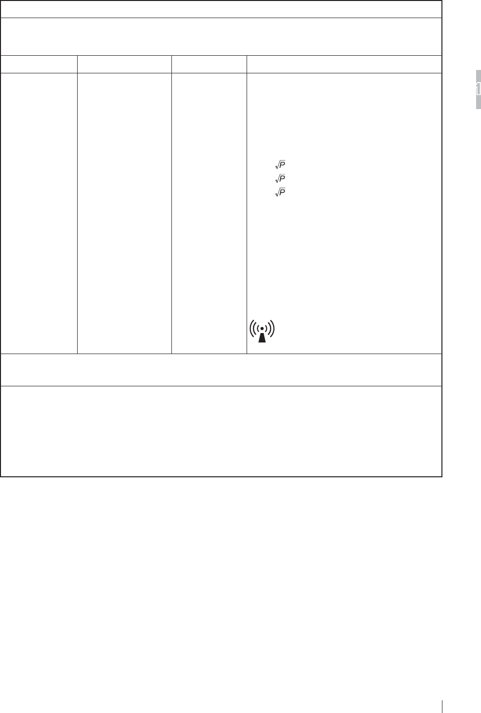
,IWKHÀDWSDQHOVHQVRULVKLWRUGURSSHGRULVVXEMHFWWR
severe shock, it may be damaged.
,IWKHIURQWDQGUHDURIWKHÀDWSDQHOVHQVRUDUHVXEMHFWWR
impact by a projection, it may be damaged.
7KHÀDWSDQHOVHQVRULVHTXLSSHGZLWKDVKRFNVHQVRU
that detects a severe impact. For details, see “Ŷ DR-ID
600PU” (page 2-3).
CAUTIONS
,IWKHVKRFNVHQVRUOLJKWVUHGFRQWDFWD)8-,),/0GHDOHU
'RQRWSXOOWKHFDEOHRIWKHÀDWSDQHOVHQVRU:LUHG
communication mode).
$OVRGRQRWSXOOWKHÀDWSDQHOVHQVRUZLWKVRPHWKLQJFDXJKW
by the cable.
Make sure that the cable is not trapped under the wheels of a
stretcher or wheelchair.
Otherwise, the cable will be damaged, causing electric shock
RU¿UH
:KHQFDUU\LQJWKHÀDWSDQHOVHQVRU:LUHGFRPPXQLFDWLRQ
mode), do not drag the sensor cable relay connector on the
ÀRRURUJURXQG0DNHDOVRVXUHWKDWQRRQHRUREMHFWFRPHV
LQWRFRQWDFWZLWKWKHÀDWSDQHOVHQVRU,WLVUHFRPPHQGHGWR
KROGWKHFRQQHFWRUZKHQFDUU\LQJWKHÀDWSDQHOVHQVRU
8QOHVVWKHVHFDXWLRQVDUHREVHUYHGWKHÀDWSDQHOVHQVRU
may be caught by an object, personal injury may result, or
properties or the connector may be damaged.
'RQRWKROGWKHÀDWSDQHOVHQVRULQRQHKDQGZKHQFDUU\LQJLW
Hold it in both the hands or under the arm.
,IDQ\RIWKHVFUHZFDSVRQWKHÀDWSDQHOVHQVRUFRPHVRII
attach a spare cap. Otherwise, artifacts may appear in the
image due to static electricity.
To ensure optimal image quality, it is recommended that you do
QRWXVHWKHÀDWSDQHOVHQVRUQHDUGHYLFHVPRWRUWUDQVIRUPHU
switching supply, etc.) that generate electromagnetic noise.
To ensure optimal image quality, it is recommended that you do
not place the cables (power cable, communication cable, etc.)
of the equipment near devices (motor, transformer, switching
supply, etc.) that generate electromagnetic noise and their
cables.
Screw
cap
DR-ID 601SE
DR-ID 600SE
1-17
FDR D-EVO Operation Manual 897N101473E
For Safe Operation
1
1.5.2 Before Exposure
The use of an air-conditioner may dramatically changes the temperature of the room where the
system is installed. This may cause dew condensation on the system, resulting in quality problems.
When an air-conditioner is used, change the temperature gradually to avoid temperature variation
in order not to cause dew condensation.
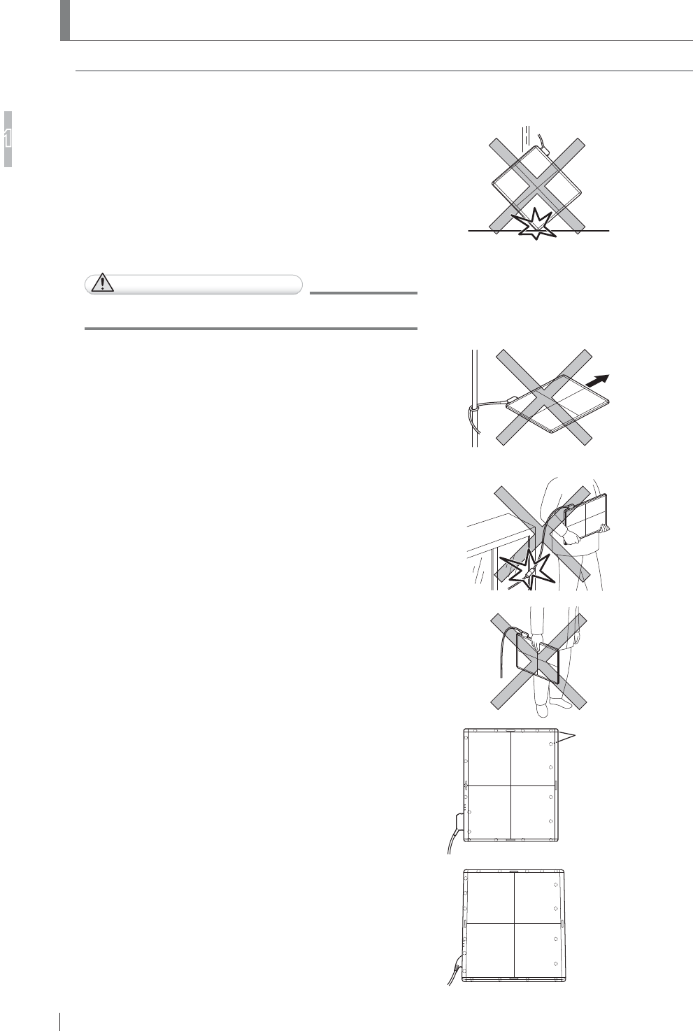
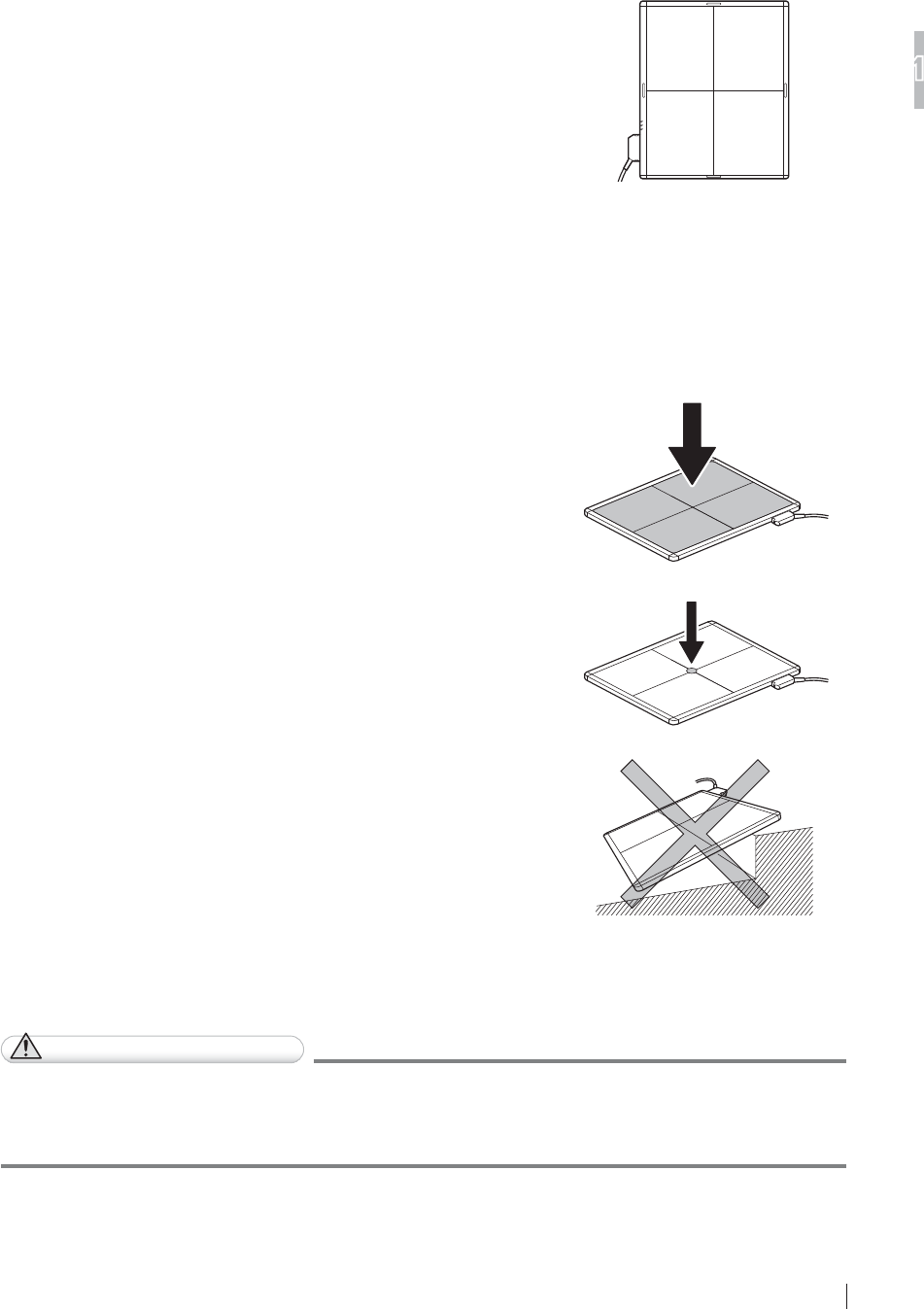
,IDQH[SRVXUHLVPDGHZLWKWKHIURQWDQGUHDURIWKHÀDWSDQHO
sensor facing the other way round, re-exposure and electric
parts may be damaged.
Exposure plane of the
flat panel sensor
'RQRWXVHWKHÀDWSDQHOVHQVRUIRUWKHUDGLRJUDSKLFH[DPLQDWLRQVWDQGHTXLSSHGZLWKDQDXWRPDWLF
loading function.
'XULQJ([SRVXUH
Before making an exposure, make sure that exposure conditions most appropriate for this system
are set.
Do not apply an excessive force to the exposure plane.
7KHVHQVRULQVLGHWKHÀDWSDQHOVHQVRUPD\EHGDPDJHG
<Load restriction>
(QWLUHVXUIDFHORDGNJ
/RFDOORDG'5,'6(NJ¡PP
'5,'6(NJ¡PP
8VHWKHÀDWSDQHOVHQVRURQDÀDWÀRRURUSODWIRUP
When an excessive force is applied to the unit when it
LVWLOWHGWKHVHQVRULQVLGHWKHÀDWSDQHOVHQVRUPD\EH
damaged.
'XULQJ&OHDQLQJ
To clean the outer surfaces, use commercially available ethanol papers for disinfection or a cleaning
cloth tightly wrung out of ethanol (or diluted neutral detergent).
CAUTIONS
Ɣ 'RQRWXVHDQH[FHVVLYHDPRXQWRIHWKDQRORUQHXWUDOGHWHUJHQWDVGRLQJVRPD\DOORZWKH
OLTXLGWRHQWHUIURPWKHJDSRQWKHRXWHUVXUIDFHVUHVXOWLQJLQWKHGDPDJHWRWKHÀDWSDQHO
sensor, or cause the labels to come off.
Ɣ 'RQRWXVHDVROYHQWVXFKDVWKLQQHURUEHQ]LQHDVLWFRUURGHVWKHRXWHUVXUIDFHV
6WRUDJH
:KHQWKHÀDWSDQHOVHQVRULVQRWLQXVHVWRUHWKHGHYLFHLQDSODFHZKHUHLWGRHVQRWIDOORUGURS
1-18 FDR D-EVO Operation Manual 897N101473E
For Safe Operation
1
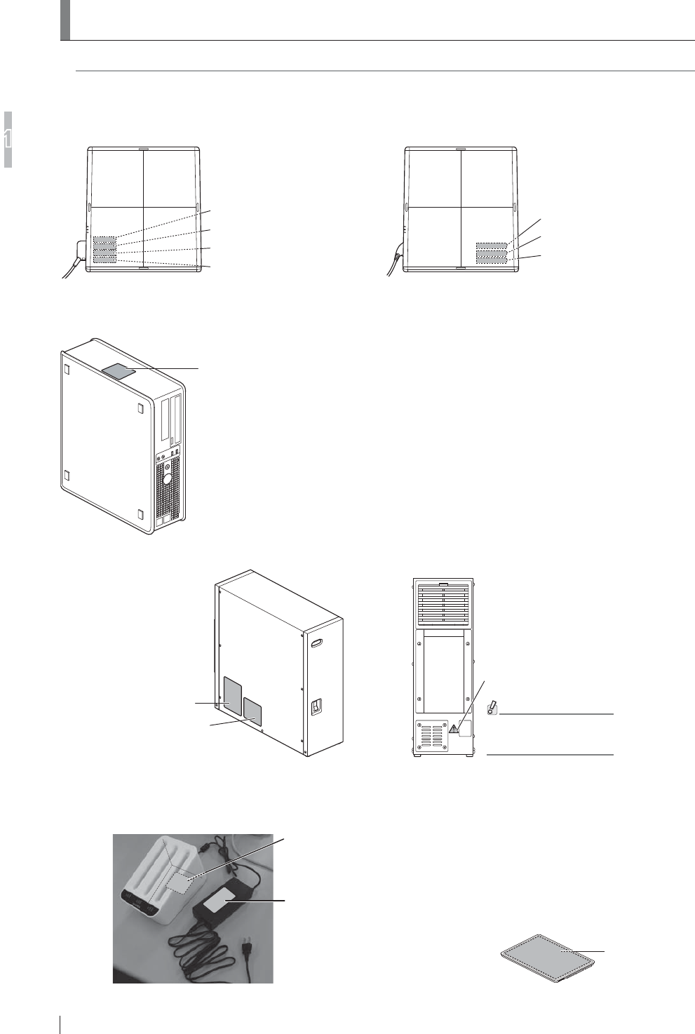
/RFDWLRQVRI/DEHOVDQG6LJQV
/RFDWLRQVRIODEHOVDQGVLJQVDI¿[HGWRWKH)'5'(92DQGWKHUHOHYDQWVDIHW\VLJQVDUHVKRZQEHORZ
1.6.1 Locations of Labels
DR-ID 600SE Caution Label
DR-ID 600SE CE Mark Label
DR-ID 600SE Identification Label
<Exposure plane>
Flat panel sensor (DR-ID 600SE)
DR-ID 601SE Caution Label
DR-ID 601SE CE Mark Label
DR-ID 601SE Identification Label
Radio law certification label
<Exposure plane>
Flat panel sensor (DR-ID 601SE)
DR-ID 600MC
Identification Label
Control cabinet (DR-ID 600MC)
DR-ID 600PU Rating Label
DR-ID 600MP System Label
DR-ID 600MP
Caution Label
For the types of
connectable cables,
consult a FUJIFILM dealer.
<Left-hand side>
Power supply unit (DR-ID 600MP)
<Rear side>
Battery pack
(optional)
Battery pack
Rating Label
Battery charger
(optional)
AC adapter (Battery charger)
Rating Label
Battery charger
Rating Label
1-19
FDR D-EVO Operation Manual 897N101473E
For Safe Operation
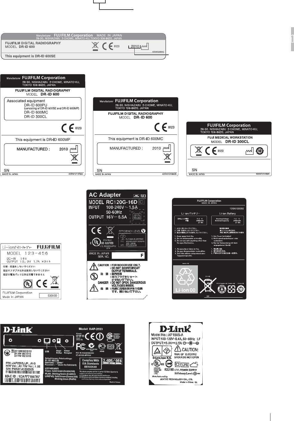
1
1.6.2 DR-ID 600
DR-ID 601SE CE Mark Label
Sample year of manufacture
DR-ID 600SE CE Mark Label
Sample year of manufacture
DR-ID 600MP System Label DR-ID 600MC Identification Label
MAR. 2010
DR-ID 300CL Identification Label
AC adapter (Battery charger)
Rating Label
Battery pack Rating Label
Battery charger Rating Label
AC adapter (Access point) Rating Label*
Access point Rating Label*
* The access point model is subject to change.
1-20 FDR D-EVO Operation Manual 897N101473E
For Safe Operation
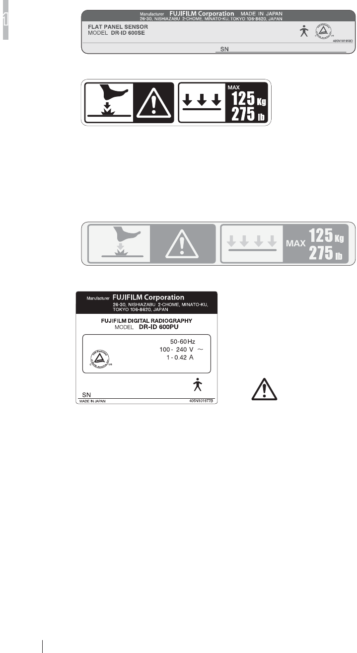
1
1.6.3 DR-ID 600PU
DR-ID 601SE Identification Label
DR-ID 600SE Identification Label
DR-ID 601SE Caution Label
Radio law certification label
DR-ID 600SE Caution Label
DR-ID 600PU Rating Label
MADE IN JAPAN
DR-ID 600MP Caution Label
1-21
FDR D-EVO Operation Manual 897N101473E
For Safe Operation
1
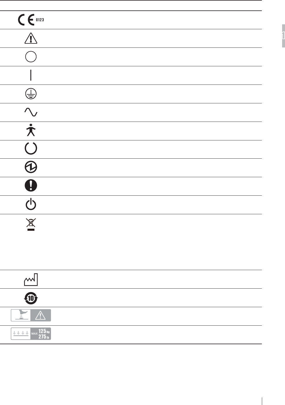
1.6.4 Safety and Other Symbols
The following safety symbols are used in the labels or on its body.
Symbol Description
This symbol indicates compliance of the equipment with Directive 93/42/EEC.
Caution (See “1.6.1 Locations of Labels” (page 1-17).)
OFF (To indicate disconnection from the mains, at least for mains switches or their
positions, and all those cases where safety is involved.)
ON (To indicate connection to the mains, at least for mains switches or their positions, and
all those cases where safety is involved.)
Protective earth (ground)
Alternating current
This symbol indicates that the equipment is a Type B Applied Part.
Ready (To indicate the machine is ready for operation.)
Electric energy
General mandatory action sign
Stand-by
This symbol indicates that this product is not to be disposed of with your household waste,
according to the WEEE Directive (2002/96/EC) and your national law. This product should
be handed over to a designated collection point.
Improper handling of this type of waste could have a possible negative impact on the
environment and human health due to potentially hazardous substances that are generally
associated with EEE.
At the same time, your cooperation in the correct disposal of this product will contribute to
the effective usage of natural resources.
For more information about waste, please contact FUJIFILM dealers.
Year of manufacture
Environmentally Friendly Use Period (EFUP)
Caution for local load (See “1.5.3 During Exposure” (page 1-16).)
Entire surface load
1-22 FDR D-EVO Operation Manual 897N101473E
For Safe Operation
1
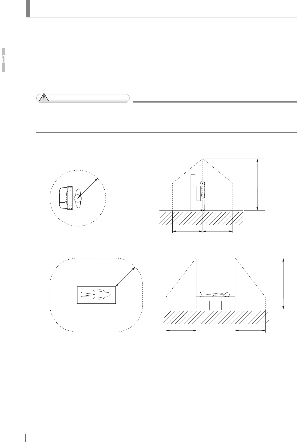
1.7 Installation Conditions
,QVWDOODWLRQ6SDFH:KHQ6HWWLQJWKH&RQWURO&DELQHWLQ
the X-ray Room
In case that the control cabinet is installed in the X-ray room, ensure a certain distance between
WKHFRQWUROFDELQHWDQGWKHXSULJKWW\SHRUEHGW\SHUDGLRJUDSKLFH[DPLQDWLRQVWDQG6HHWKH¿JXUH
below for reference.
)RUWKHSURGXFWVWKDWFDQEHLQVWDOOHGLQSDWLHQWHQYLURQPHQWVHH³6\VWHP&RQ¿JXUDWLRQ´
(page 2-1).
CAUTIONS
'RQRWLQVWDOOWKHSRZHUVXSSO\XQLWFRQWUROFDELQHWLPDJHSURFHVVLQJXQLW%DWWHU\
FKDUJHURSWLRQDODQG$FFHVVSRLQWLQDQDUHDRIWKH;UD\URRPZKHUHWKHXVHUFDQHDVLO\WULS
over. Falls could result in injury.
Ŷ 8SULJKWW\SH
2.5m 2.5m
2.5m
2.5m
Ŷ %HGW\SH
2.5m 2.5m
2.5m
2.5m
2-1
FDR D-EVO Operation Manual 897N101473E
6\VWHP&RQILJXUDWLRQ3URGXFW2YHUYLHZ
2
Chapter 26\VWHP&RQILJXUDWLRQ
(Product Overview)
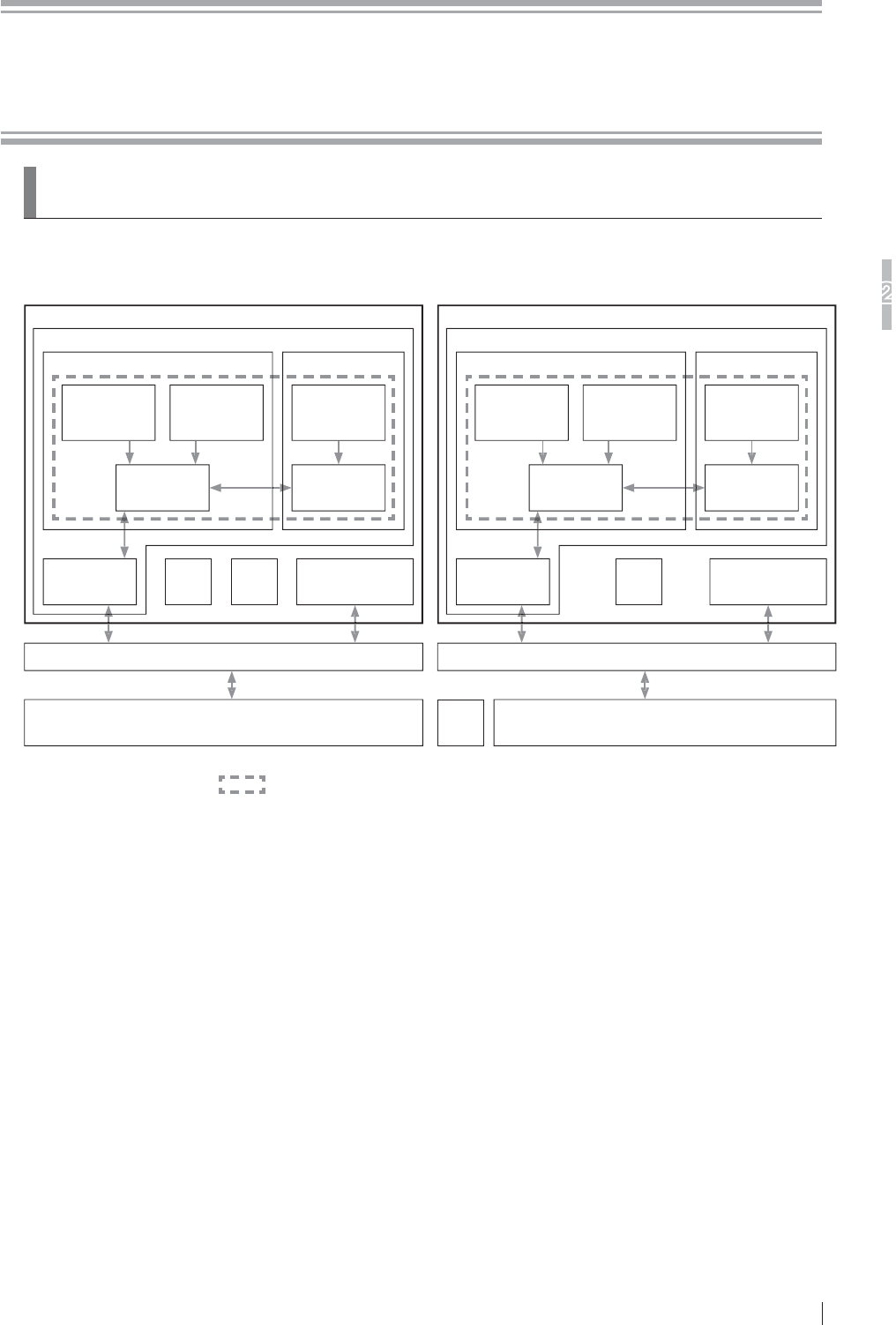
2.1 FDR D-EVO
6\VWHP&RQ¿JXUDWLRQ
For the U.S. For other countries
DR-ID 600
DR-ID 600RU
DR-ID 600PU DR-ID 600PU
Image processing unit of other digital radiography system
DR-ID 300CL
Flat panel sensor
DR-ID 600SE or
DR-ID 601SE
Flat panel sensor
DR-ID 600SE or
DR-ID 601SE
Flat panel sensor
DR-ID 600SE or
DR-ID 601SE
Battery
charger
Access
point*
Power supply unit
DR-ID 600MP
Power supply unit
DR-ID 600MP
Control cabinet
DR-ID 600MC
Image processing unit
DR-ID 300CL
Hub
DR-ID 600
DR-ID 600RU
DR-ID 600PU DR-ID 600PU
Image processing unit of other digital radiography system
DR-ID 300CL
Flat panel sensor
DR-ID 600SE or
DR-ID 601SE
Flat panel sensor
DR-ID 600SE or
DR-ID 601SE
Flat panel sensor
DR-ID 600SE or
DR-ID 601SE
Battery
charger
Access
point*
Power supply unit
DR-ID 600MP
Power supply unit
DR-ID 600MP
Control cabinet
DR-ID 600MC
Image processing unit
DR-ID 300CL
Hub
The products in can be installed in patient environment.
7KH)'5'(92FRQVLVWVRIWKH'5,'58DQGWKHLPDJHSURFHVVLQJXQLW'5,'&/
$QDFFHVVSRLQWLVXVHGRQO\LQZLUHOHVVFRPPXQLFDWLRQPRGH
7KHFRQ¿JXUDWLRQRIWKHV\VWHPYDULHVGHSHQGLQJRQWKHFRXQWU\

2-2 FDR D-EVO Operation Manual 897N101473E
6\VWHP&RQILJXUDWLRQ3URGXFW2YHUYLHZ
2
2.1.2 Features of the FDR D-EVO
This section describes the main features of the FDR D-EVO.
7KHH[WHUQDOGLPHQVLRQVDQGWKHZHLJKWRIWKHÀDWSDQHOVHQVRUDUHWKHVDPHDVWKRVH
RIWKHFRQYHQWLRQDOFDVVHWWHXVHGIRUJHQHUDOH[SRVXUH'XHWRWKLVIHDWXUHWKHÀDWSDQHO
sensor can be inserted into the radiographic examination stand that has been used,
allowing the user to avoid cassette replacement.
7KHÀDWSDQHOVHQVRUFDQEHFRQQHFWHGGLVFRQQHFWHGZLWKWKHUHOD\FRQQHFWRURIWKH
FRQQHFWLRQFDEOH7KLVDOORZVWKHXVHUWRFDUU\WKHÀDWSDQHOVHQVRUDQGLQVHUWUHPRYHLW
into/from the upright-type or bed-type radiographic examination stand more easily.
7KHOLJKWZHLJKWDQGWKHWKLQDQGURXQGGHVLJQLQFUHDVHWKHRSHUDELOLW\RIWKHÀDWSDQHO
sensor, making it possible to place it under a lying patient.
4 An image can be displayed on the Console within approximately 5 seconds after making an
exposure.
2ZLQJWRWKHKLJKO\VHQVLWLYHÀDWSDQHOVHQVRU;UD\H[SRVXUHGRVHFDQEHUHGXFHG
accordingly.
6 Due to the effects of digital image processing, the system produces X-ray images that have
a high diagnostic value and are easy to observe.
7 The system has a wide latitude for incident X-rays so that a large amount of X-ray
diagnostic information is obtained.
8 As the system has a wide latitude and an automatic sensitivity adjustment function, its
X-ray images are not affected by small changes in X-ray exposure conditions. Therefore,
consistent image density is obtained for all images.
9 Image processing parameters are automatically selected through an anatomical region
selection system from the Console.
10 Multi-objective Frequency Processing (MFP), a newly introduced image processing
function, not only improves the image quality also achieves high-speed image processing.
11 A DICOM-conformed open network can be supported by connecting the Console.
:LWKWKHÀDWSDQHOVHQVRU'5,'6(ZLUHOHVVFRPPXQLFDWLRQPRGHRUZLUHG
communication mode can be selected. In wireless communication mode, exposures can be
performed without connecting the cable.
2-3
FDR D-EVO Operation Manual 897N101473E
6\VWHP&RQILJXUDWLRQ3URGXFW2YHUYLHZ
2
2.2 Unit Names and the Functions
Unit names and the functions of the FDR D-EVO are described below.
2.2.1 DR-ID 600
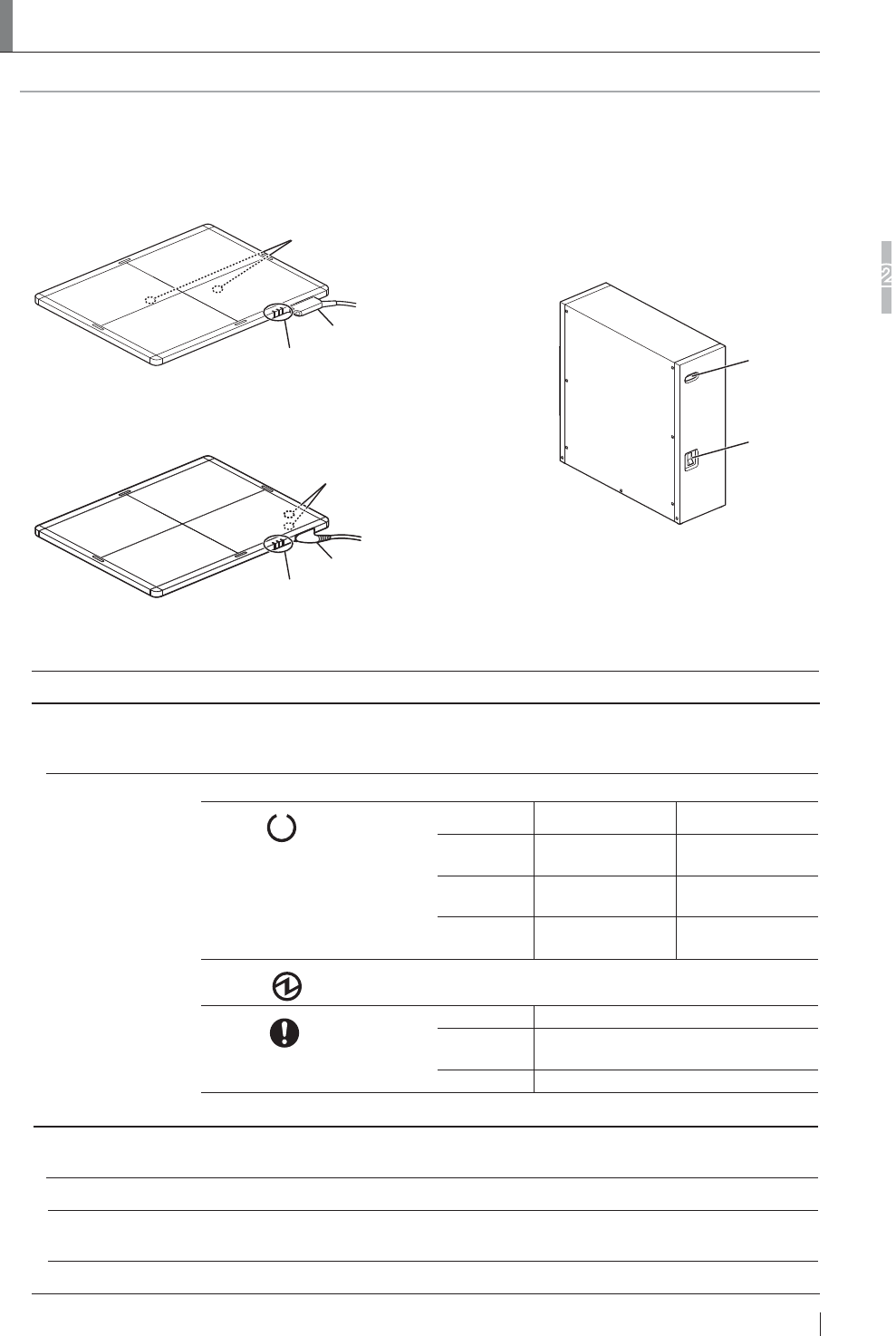
ŶDR-ID 600PU
Status lamp
Shock sensor display (2 places)
: Lights red when the shock
sensor detects a severe impact.
Connector
Flat panel sensor (DR-ID 600SE)
* Exposure plane is shown in this figure.
Status lamp
Shock sensor display (2 places)
: Lights red when the shock
sensor detects a severe impact.
Connector
Flat panel sensor (DR-ID 601SE)
* Exposure plane is shown in this figure.
Main switch
Power
status LED
Power supply unit (DR-ID 600MP)
Name Description
Flat panel sensor
(DR-ID 601SE)
(DR-ID 600SE)
A unit incorporating a GOS indirect panel.
7KHUHDUHWZRW\SHVRIÀDWSDQHOVHQVRUV'5,'6(ZLUHOHVVZLUHGFRPPXQLFDWLRQ
mode) and DR-ID 600SE (wired communication mode).
Status lamp Indicates the equipment status by LEDs.
READY (Green)
(In wireless communication
mode, the status of the battery
pack is indicated. In wired
communication mode, whether or
not exposures can be performed
is indicated.)
Wireless Wired
OK (Exposure
possible)
Exposure possible
Blinks for 1.0
second.
Less than 10 min.
(Charge required)
During exposure
sequence
Off Empty (Power
OFF)
Ready
POWER (Green) Comes on when the system is turned on.
ERROR (Orange)
On Communication not possible.
Blinks for 1.0
second.
Error occurred
Off Normal
* All LEDs are off when the equipment is off.
Power supply unit
(DR-ID 600MP)
6XSSOLHVWKHSRZHUWRWKHÀDWSDQHOVHQVRUDQGFRQQHFWVWKHÀDWSDQHOVHQVRUDQGWKH
control cabinet.
Main switch 6XSSOLHVWKHSRZHUWRWKHÀDWSDQHOVHQVRUDQGWKHLQVLGHRIWKHSRZHUVXSSO\XQLW
Remote switch
(optional)
7XUQVRQRIIWKHSRZHUWRWKHÀDWSDQHOVHQVRU
Power status LED Displays ON/OFF of the power supply unit.
2-4 FDR D-EVO Operation Manual 897N101473E
6\VWHP&RQILJXUDWLRQ3URGXFW2YHUYLHZ
2
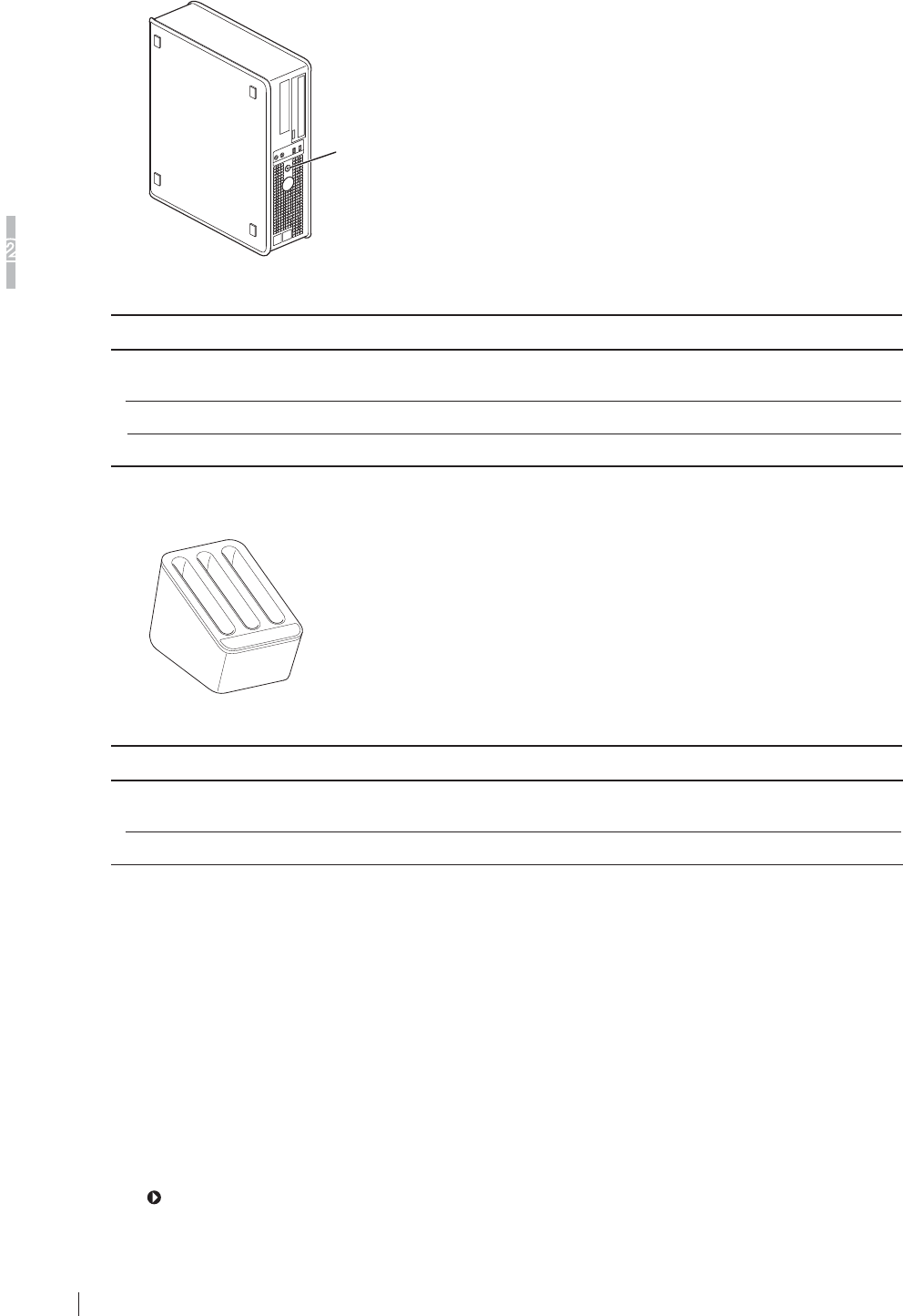
ŶDR-ID 600MC
Main switch/
power status LED
Control cabinet (DR-ID 600MC)
Name Description
Control cabinet
(DR-ID 600MC)
$SHUVRQDOFRPSXWHUXVHGIRUFRQWUROOLQJWKHÀDWSDQHOVHQVRUDQG
performing image processing.
Main switch Supplies the power to the control cabinet.
Power status LED Displays ON/OFF of the control cabinet.
Ŷ %DWWHU\FKDUJHU2SWLRQDO
Battery charger
Name Description
Battery charger &KDUJHVWKHEDWWHU\SDFNRSWLRQDOIRUWKHÀDWSDQHOVHQVRU'5,'
601SE). Three packs can be charged at the same time.
Charge status indicator LED Indicates charge status.
ŶAccess point
3URGXFWFRPSOLDQWZLWK,(&8/36(RU-,6
Compliant with IEEE802.11n [W52] (in the 5.2GHz band) /36, 40, 44, 48ch
:/$1LQWHUIDFH%$6(7%$6(7;PLQLPXPUHTXLUHPHQWV
/$1LQWHUIDFH%$6(7%$6(7;PLQLPXPUHTXLUHPHQWV
$YDLODEOH26/LQX[
Compliant with UL
Compliant with FCC part15
ŶDR-ID 300CL
For the unit names and functions of the DR-ID 300CL, see the “DR-ID 300CL Operation Manual”.
2-5
FDR D-EVO Operation Manual 897N101473E
6\VWHP&RQILJXUDWLRQ3URGXFW2YHUYLHZ
2
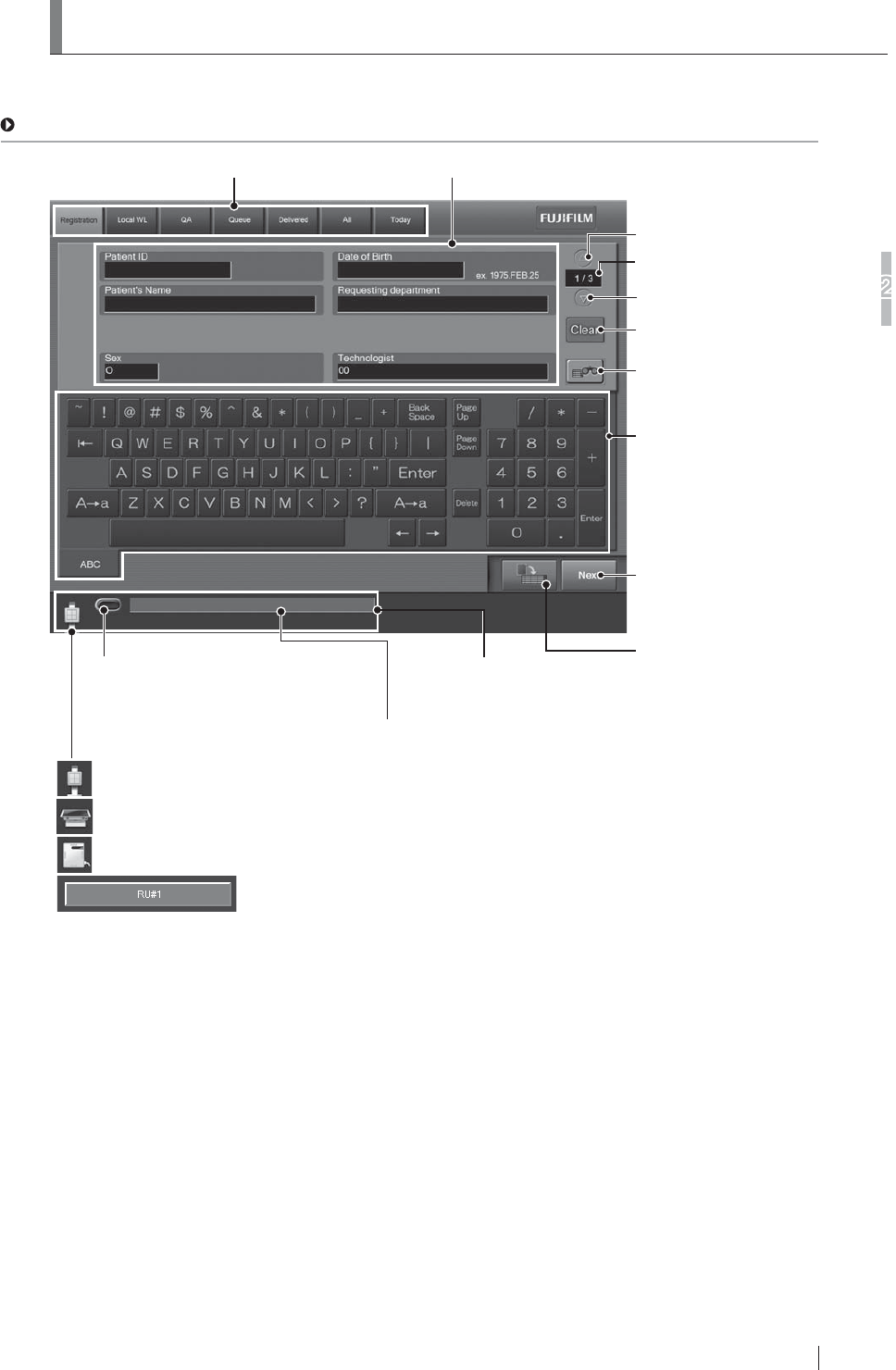
&RQVROH'LVSOD\&RQILJXUDWLRQ
When the self-initialization process ends, the Patient Information Input Screen will appear on the
Console display.
For details, see “DR-ID 300CL Operation Manual”.
List tab
Displays various lists.
Patient information input field
Input patient information.
Shows page number of the
patient information input field.
Turns one page backward.
Turns one page forward.
Clears patient information
(except for technologist).
Operates the Patient Information
Database function to input patient
information.
Touch panel soft keyboard
Used to input characters in the
patient information input field.
Reserves a study.
Terminates patient information
input, and proceeds to exposure
menu selection.
Exposure enable/disable status
Indicates whether exposure is enabled
(lights green) or disabled.
:KHQWKH;UD\HTXLSPHQWXVHGLVXSULJKWW\SH
:KHQWKH;UD\HTXLSPHQWXVHGLVEHGW\SH
:KHQPDNLQJDQH[SRVXUHGLUHFWO\ZLWKWKHIODWSDQHOVHQVRUDIWHUUHPRYLQJLWIURPWKHUDGLRJUDSKLFH[DPLQDWLRQVWDQG
:KHQWKH)&5FDVVHWWHLVXVHGH[DPSOH
For details, see “DR-ID 300CL Operation Manual”.
Operating status
Displays the operating status, error messages, and other information.
X-ray equipment status
Displays the operating status of the X-ray equipment to which the Console
is connected.
2-6 FDR D-EVO Operation Manual 897N101473E
6\VWHP&RQILJXUDWLRQ3URGXFW2YHUYLHZ
2
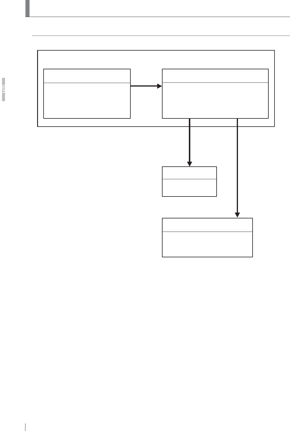
5RXWLQH2SHUDWLRQ'LDJUDP
7KHV\VWHPFRQ¿JXUDWLRQDQGWKHURXWLQHRSHUDWLRQGLDJUDPIRUWKH)'5'(92LVDVIROORZV
Image data
Image data
Imager
Film output
Image Management Workstation
DICOM-conformed
open network supported
DR-ID 300CL
Patient information entry
Exposure region / study menu selection
Image processing, etc.
Image data
DR-ID 600PU and DR-ID 600MC
FDR D-EVO (DR-ID 600)
X-ray exposure
Image reading
3-1
FDR D-EVO Operation Manual 897N101473E
Basic Operation
3
Chapter 3 Basic Operation
3UHSDULQJWKH)ODW3DQHO6HQVRU
7KLVVHFWLRQGHVFULEHVKRZWRSUHSDUHWKHÀDWSDQHOVHQVRU
3.1.1 Type of Flat Panel Sensor
'5,'6(:LUHOHVVFRPPXQLFDWLRQPRGHRUZLUHGFRPPXQLFDWLRQPRGHLVDYDLODEOH:KHQ
used in wireless communication mode, an access point*1, battery pack (optional)
and battery charger (optional) are required.
*1 In the countries other than the U.S., an access point is not included as a component of the system. For
GHWDLOVLQFOXGLQJLQVWDOODWLRQFRQVXOWRXURI¿FLDOGHDOHU
Product compliant with IEC60950, UL60950, PSE or JIS
Compliant with IEEE802.11n [W52] (in the 5.2GHz band) /36, 40, 44, 48ch
:/$1LQWHUIDFH%$6(7%$6(7;PLQLPXPUHTXLUHPHQWV
/$1LQWHUIDFH%$6(7%$6(7;PLQLPXPUHTXLUHPHQWV
$YDLODEOH26/LQX[
Compliant with UL
Compliant with FCC part15
CAUTIONS
Use only one access point. A communication error may occur if two units or more are used.
'5,'6(:LUHGFRPPXQLFDWLRQPRGH
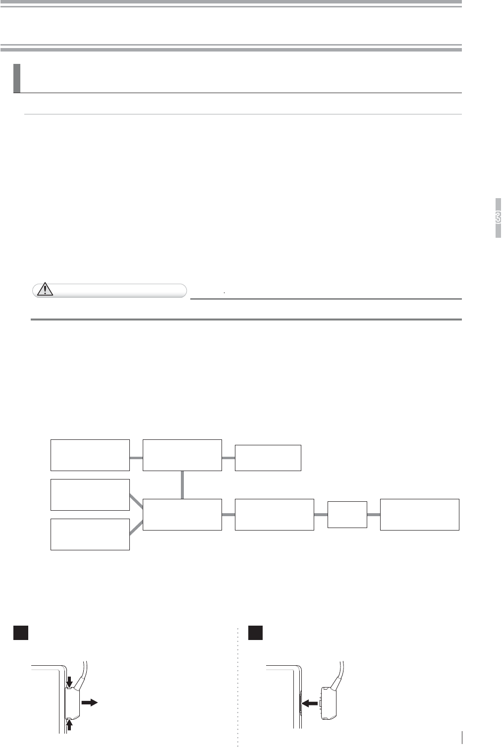
3.1.2 Number of the Connectable Flat Panel Sensors
7RHQDEOHWKHÀDWSDQHOVHQVRULWV,'QHHGVWREHUHJLVWHUHGLQDGYDQFHE\D)8-,),/0GHDOHU
8SWR¿YHÀDWSDQHOVHQVRUVFDQEHUHJLVWHUHG
8SWRWKUHHÀDWSDQHOVHQVRUV2 can be connected to the power supply unit at the same time.
:KHQWKUHHÀDWSDQHOVHQVRUVDUHFRQQHFWHGDWWKHVDPHWLPHWZRSRZHUVXSSO\XQLWDUHUHTXLUHG
Flat panel sensor
(DR-ID 600SE or
DR-ID 601SE)
Image processing unit
(DR-ID 300CL)
Access point
Control cabinet
(DR-ID 600MC)
Power supply unit
(DR-ID 600MP)
Hub
Flat panel sensor
(DR-ID 600SE or
DR-ID 601SE)
Flat panel sensor
(DR-ID 600SE or
DR-ID 601SE)
Power supply unit
(DR-ID 600MP)
&RQQHFWLQJ'LVFRQQHFWLQJWKH)ODW3DQHO6HQVRU'5,'
601SE) Connector
When used in wireless communication mode, disconnect the connector.
1Disconnect the connector.
Press the latches on both sides of the connector.
2Connect the connector.
Press the connector into the insertion section.
*Frequency Tolerance: ±20ppm
3-2
Basic Operation
3
FDR D-EVO Operation Manual 897N101473E
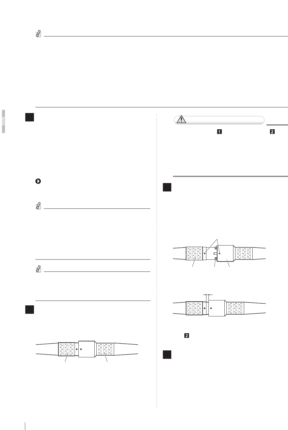
&RQQHFWLQJ'LVFRQQHFWLQJWKH6HQVRU&DEOH5HOD\
Connector for the Flat Panel Sensor (DR-ID 600SE)
Follow the procedure below to connect/disconnect the sensor cable relay connector.
'RQRWFRQQHFWWKHÀDWSDQHOVHQVRUWRWKHSRZHUVXSSO\XQLWRWKHUWKDQRIWKH)'5'(92
2WKHUZLVHWKHFRQQHFWRUPD\EHGDPDJHG
'RQRWFRQQHFWWKHÀDWSDQHOVHQVRUXQUHJLVWHUHGWRWKHV\VWHP2WKHUZLVHWKHSRZHUWRWKH
ÀDWSDQHOVHQVRUZLOOEHGLVFRQQHFWHGDXWRPDWLFDOO\)RUGHWDLOVRQWKHUHJLVWUDWLRQFRQWDFWD
FUJIFILM dealer.
:KHQFRQQHFWLQJGLVFRQQHFWLQJWKHVHQVRUFDEOHUHOD\FRQQHFWRUDOZD\VKROGWKHJULSRIWKHFRQQHFWRU
7KHZLUHLQVLGHPD\EHEURNHQLI\RXFRQQHFWGLVFRQQHFWE\KROGLQJWKHFDEOH
,I\RXWXUQWKHRXWHUEXVKLQJRIWKHJULSWKHFDEOHORFNEHFRPHVORRVHFDXVLQJDVKRUWFLUFXLWRIWKHFDEOH
'RQRWGURSWKHVHQVRUFDEOHUHOD\FRQQHFWRUZKHQFRQQHFWLQJGLVFRQQHFWLQJLW2WKHUZLVH
SHUVRQDOLQMXU\PD\UHVXOWRUSURSHUWLHVRUWKHFRQQHFWRUPD\EHGDPDJHG
1 0DNHVXUHWKDWWKH5($'<ODPSRIWKHÀDW
SDQHOVHQVRULVQRWEOLQNLQJDQGSUHVV
the OFF side of the power supply unit.
$OWHUQDWLYHO\WXUQRIIWKHÀDWSDQHOVHQVRU
E\SUHVVLQJWKHRSHUDWLRQEXWWRQRQWKH
RSWLRQDOUHPRWHVZLWFKDQGPDNHVXUHWKDW
WKH32:(5ODPSRIWKHÀDWSDQHOVHQVRU
turns off.
For the external view of the optional remote
switch, see “O.2 Using the Remote Switch”
(page O-2).
The remote switch can be simultaneously
FRQQHFWHGWRERWKWKHXSULJKWW\SHDQG
the bed type.
7KHUHOD\FRQQHFWRUFDQEHFRQQHFWHG
GLVFRQQHFWHGE\WXUQLQJRIIHLWKHURIWKH
remote switches.
You can proceed to the next step even if
DQHUURUPHVVDJHDSSHDUVDIWHUWXUQLQJ
off the power supply unit.
2 7RGLVFRQQHFWKROGWKHJULSV$DQG%RI
ERWKWKHFRQQHFWRUVDQGWKHQSXOOWKHJULS
$RIWKHÀDWSDQHOVHQVRUWRXQORFN
Flat panel sensor
Grip BGrip A
Power supply unit
CAUTIONS
,I\RXVNLS6WHS and perform Step ,
a communication error occurs. In such a
FDVHWXUQWKHSRZHUEDFNRQWRWKHSRZHU
VXSSO\XQLW1RWHKRZHYHUWKDWUHSHDWLQJ
WKLVDFWLRQPD\UHVXOWLQGDPDJHWRWKH
HTXLSPHQW
3 7RFRQQHFWDOLJQWKHSRVLWLRQLQJPDUNV
and then push the connectors in.
Align the positioning mark on the connector of the
SRZHUVXSSO\XQLWZLWKWKDWRIWKHÀDWSDQHOVHQVRU
and then insert the connectors by slightly turning
them.
Positioning mark
GripGrip Locking latch
Push in until you feel a click.
2 to 3mm
3XVKIXUWKHULQWRWKHSRVLWLRQVKRZQLQWKH¿JXUHLQ
Step until you feel a click again to lock them into
place.
4Press the ON side of the main switch of the
power supply unit, or press the operation
button on the optional remote switch.
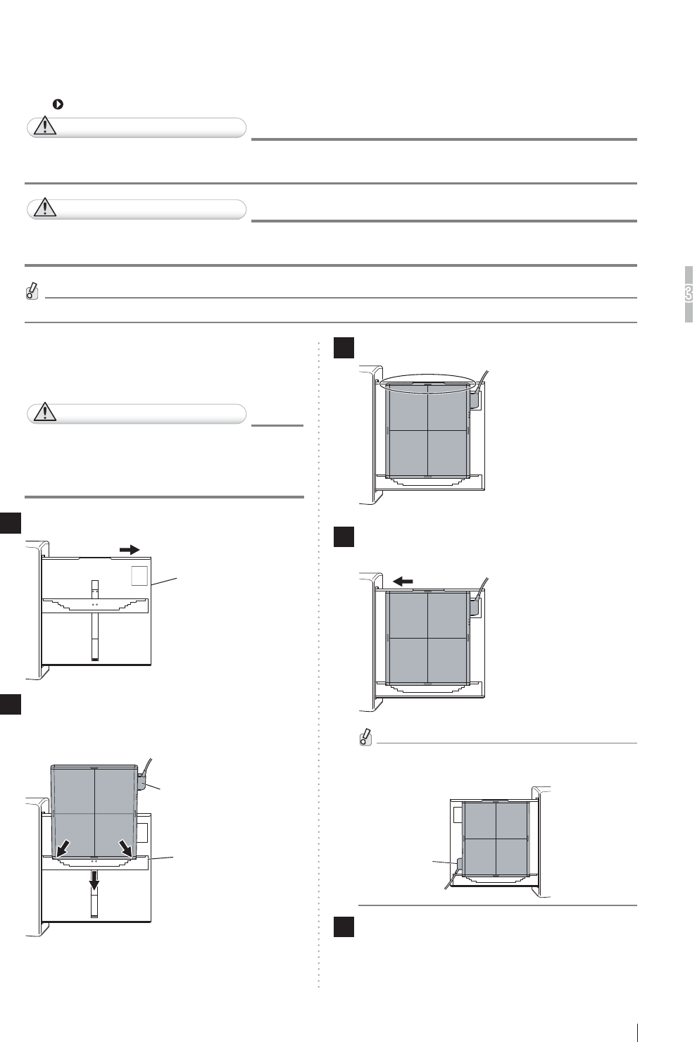
3-3
Basic Operation
3
FDR D-EVO Operation Manual 897N101473E
,QVHUWLQJ5HPRYLQJWKH)ODW3DQHO6HQVRULQWRIURPWKH
5DGLRJUDSKLF([DPLQDWLRQ6WDQG
)ROORZWKHSURFHGXUHEHORZWRLQVHUWUHPRYHWKHÀDWSDQHOVHQVRULQWRIURPWKHUDGLRJUDSKLF
examination stand.
For details, see the Operation Manual for the radiographic examination stand.
CAUTIONS
)RUWKHSRVLWLRQLQJDWWKHWLPHRILQVHUWLQJUHPRYLQJWKHÀDWSDQHOVHQVRUVHHWKH2SHUDWLRQ
0DQXDOIRUWKHUDGLRJUDSKLFH[DPLQDWLRQVWDQG
CAUTIONS
%HFDUHIXOQRWWRKDYH\RXU¿QJHUVFDXJKWZKHQLQVHUWLQJUHPRYLQJWKHÀDWSDQHOVHQVRULQWR
IURPWKHUDGLRJUDSKLFH[DPLQDWLRQVWDQG
)RUWKHHIIHFWLYHDUHDRIWKHÀDWSDQHOVHQVRUVHH³Ŷ'5,'38´SDJHA-4).
>@8SULJKWW\SH
:KHQLQVHUWLQJIURPWKHULJKWKDQGVLGH
CAUTIONS
:KHQLQVHUWLQJWKHÀDWSDQHOVHQVRULQWR
WKHUDGLRJUDSKLFH[DPLQDWLRQVWDQGGLUHFW
the exposure plane toward the X-ray tube.
1Pull out the tray.
Tray
2
,QVHUWWKHÀDWSDQHOVHQVRULQWRWKHFDVVHWWH
receive while the connector directed to the
XSSHUULJKWDQGWKHQPRYHLWGRZQZDUGV
Connector
Cassette receive
3
6HWWKHÀDWSDQHOVHQVRUWRWKHXSSHUSDUWRIWKHWUD\
4 3XVKWKHWUD\EDFNLQWRSODFHDIWHUVHWWLQJ
WKHÀDWSDQHOVHQVRU
:KHQLQVHUWLQJWKHÀDWSDQHOVHQVRUIURPWKHOHIW
hand side, direct the connector to the lower left.
Connector
5 :KHQUHPRYLQJWKHÀDWSDQHOVHQVRU
Pull out the tray, push the cassette receive
GRZQZDUGVDQGWKHQUHPRYHWKHÀDWSDQHOVHQVRU
Push the tray back into place.
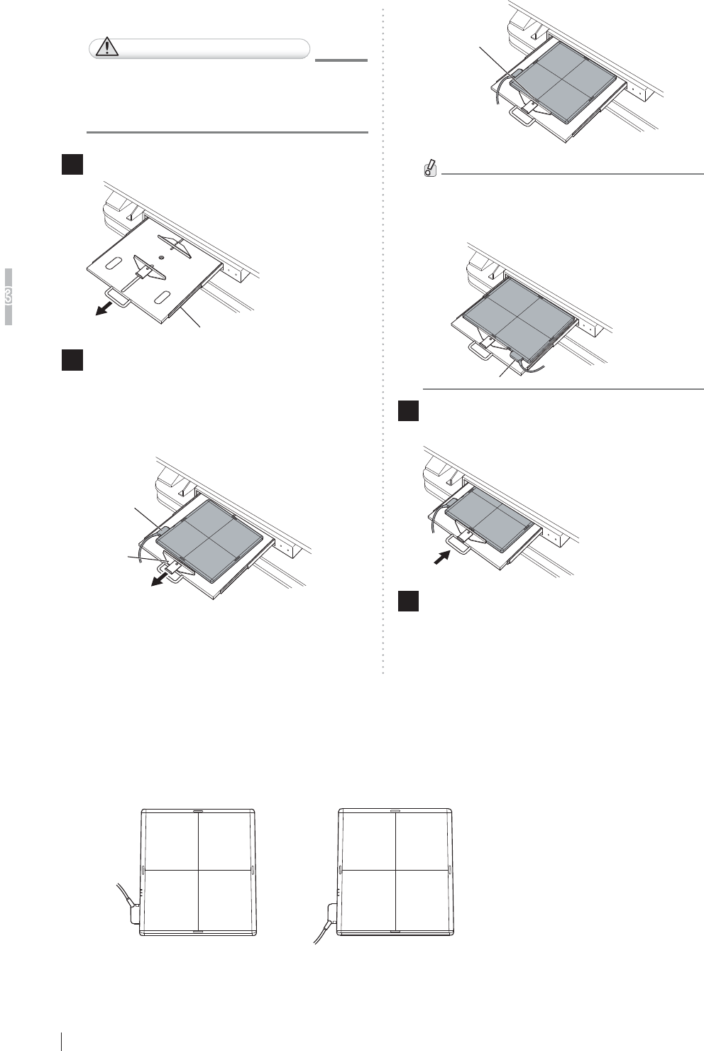
3-4
Basic Operation
3
FDR D-EVO Operation Manual 897N101473E
[2] Bed type
CAUTIONS
:KHQLQVHUWLQJWKHÀDWSDQHOVHQVRU
WRWKHUDGLRJUDSKLFH[DPLQDWLRQVWDQG
direct the exposure plane upwards.
1 3XOORXWWKHWUD\E\XVLQJWKHKDQGOH
Tray
2 3XOOWKHFDVVHWWHVWRSSHUDQGVHWWKHÀDW
SDQHOVHQVRUVRWKDWLWVFHQWHUPDUNLV
DOLJQHGZLWKWKHFHQWHURIWKHVWRSSHU
3RVLWLRQWKHFRQQHFWRURIWKHÀDWSDQHOVHQVRUDV
VKRZQLQWKH¿JXUHEHORZ
Cassette
stopper
Connector
Center mark
:KHQVHWWLQJWKHÀDWSDQHOVHQVRU
horizontally, position the connector as
VKRZQLQWKH¿JXUHEHORZ
Connector
3 3XVKWKHWUD\EDFNLQWRSODFHE\XVLQJWKH
KDQGOHDIWHUVHWWLQJWKHÀDWSDQHOVHQVRU
4 :KHQUHPRYLQJWKHÀDWSDQHOVHQVRU
Hold the handle and pull out the tray. Remove the
ÀDWSDQHOVHQVRUZKLOHSXOOLQJWKHFDVVHWWHVWRSSHU
and then push the tray back into place.
&KDQJLQJWKH'LUHFWLRQRIWKH)ODW3DQHO6HQVRU
Connector
7KHGLUHFWLRQRIWKHFRQQHFWRURIWKHÀDWSDQHOVHQVRUFDQEHFKDQJHGGHSHQGLQJRQKRZLWLV
inserted into the radiographic examination stand.
To change the direction, contact a FUJIFILM dealer.
When shipped After changing the direction
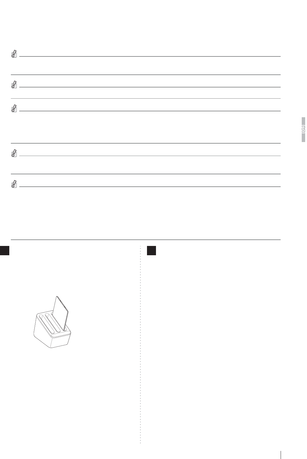
3-5
Basic Operation
3
FDR D-EVO Operation Manual 897N101473E
&KDUJLQJWKH%DWWHU\3DFN2SWLRQDOIRUWKH)ODW3DQHO
Sensor (DR-ID 601SE)
When used in wireless communication mode, charge the battery pack using the battery charger
(optional).
When the battery pack is fully charged, exposures for a maximum of approximately 200 images can be
performed. However, the number varies depending on the usage conditions.
The capacity of the battery is displayed on the READY status lamp and in the Console display.
When the remaining capacity of the battery pack becomes “Less than 10 min.” (the READY status lamp blinks
every one second), exposures cannot be performed. If this happens, perform the following operations.
Replace or charge the battery pack.
&RQQHFWWKHFRQQHFWRUWRWKHÀDWSDQHOVHQVRU
:KHQWKHFRQQHFWRULVFRQQHFWHGWRWKHÀDWSDQHOVHQVRUH[SRVXUHVLQZLUHGFRPPXQLFDWLRQPRGHDQGFKDUJLQJ
the battery pack can be performed. However, this type of charging is not recommended.
Charge the battery pack using the battery charger.
,QZLUHOHVVFRPPXQLFDWLRQPRGHZKHQWKHUHPDLQLQJFDSDFLW\RIWKHEDWWHU\SDFNEHFRPHVLQVXI¿FLHQW
H[SRVXUHVDUHSURKLELWHGDQGWKH5($'<VWDWXVODPSEOLQNVHYHU\RQHVHFRQG,IWKHÀDWSDQHOVHQVRULVXVHGLQ
wireless communication mode for another 10 minutes or so, the battery pack is not charged even if the SE cable
is connected. If this happens, remove the battery pack and charge it using the battery charger. When the battery
pack is charged using the battery charger for about one minute, charging the battery pack by connecting the SE
cable become available.
1 6HWWKHEDWWHU\SDFNLQWKHEDWWHU\FKDUJHU
When the battery pack is set, a buzzer sound is
generated and the charge status indicator LED
lights.
Three battery packs can be charged at the same
time.
2 :KHQEDWWHU\FKDUJHLVFRPSOHWHGUHPRYH
WKHEDWWHU\SDFN
When battery charge is completed, the charge status
indicator LED changes from blinking to lighting.
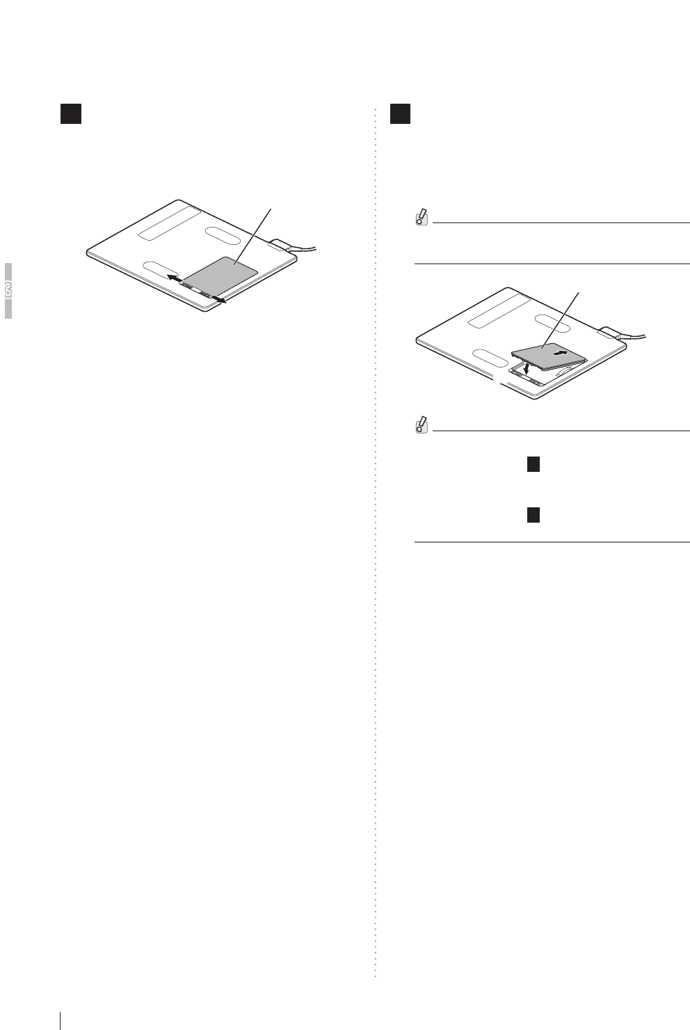
3-6
Basic Operation
3
FDR D-EVO Operation Manual 897N101473E
,QVWDOOLQJ5HPRYLQJWKH%DWWHU\3DFN2SWLRQDOIRUWKH
Flat Panel Sensor (DR-ID 601SE)
)ROORZWKHSURFHGXUHEHORZWRLQVWDOOUHPRYHWKHEDWWHU\SDFNIRUWKHÀDWSDQHOVHQVRU'5,'
601SE).
1Remove the battery cover.
3ODFHWKHÀDWSDQHOVHQVRUZLWKWKHEDFNVLGHIDFLQJ
upward and then press the right-hand and left-hand
slide locks to remove the battery cover.
Battery cover
2 ,QVWDOOWKHEDWWHU\SDFN
$OLJQWKHEDWWHU\SDFNZLWKWKHÀDWSDQHOVHQVRU'5
ID 601SE) by using the guide marks. While pressing
the battery pack (1), press down the opposite side
DVVKRZQLQWKH¿JXUHEHORZ
When the battery pack is installed, the power is
automatically turned on.
Battery pack
(1)
(2)
To remove the battery pack, perform the same
procedure as Step 1(removing the battery
cover).
To install the battery cover, perform the same
procedure as Step 2(installing the battery
pack).
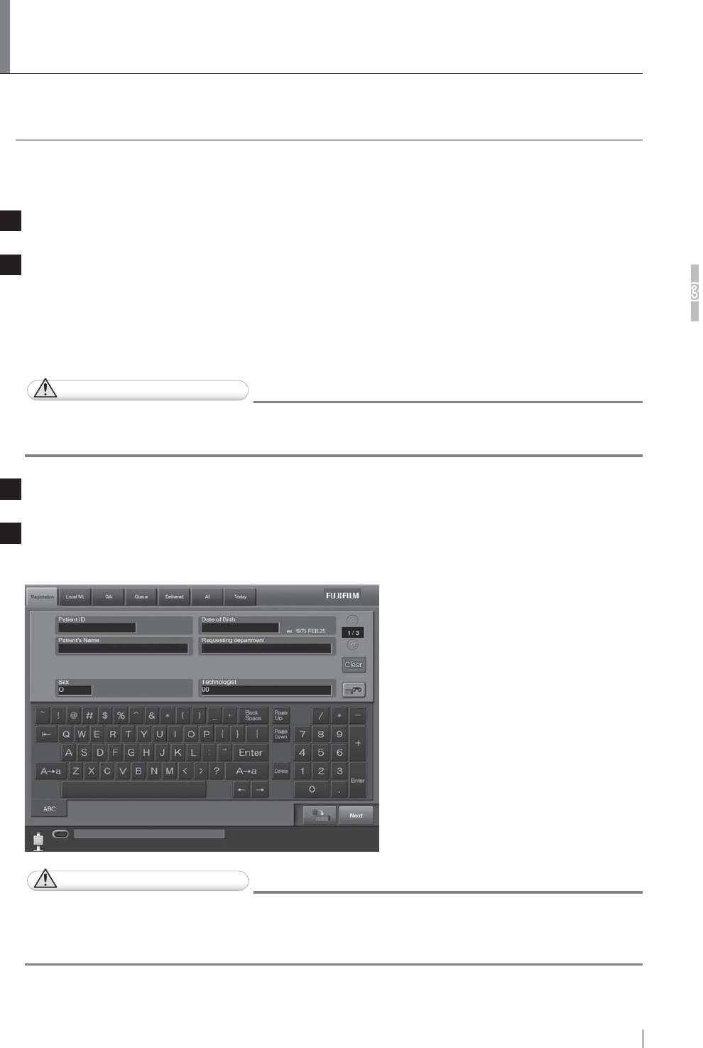
3-7
FDR D-EVO Operation Manual 897N101473E
Basic Operation
3
6WDUWLQJ8SDQG6KXWWLQJ'RZQWKH
System
This section explains how to start up and shut down the system. To start up the system, operations are
required on the FDR D-EVO main unit and on the Console.
To shut down the entire system, operations are required only on the Console.
6WDUWLQJ8SWKH6\VWHP
1Press the ON side of the main switch of the power supply unit, if its power status LED is not lit.
2 $IWHUFRQ¿UPLQJWKHIROORZLQJLWHPVSUHVVWKHSRZHUVZLWFKIRUWKH&RQVROHWRVWDUWWKH
initialization process.
$OOFDEOHVVKRXOGEHFRQQHFWHGSURSHUO\
1RPHGLDVKRXOGEHLQVHUWHGLQWRWKH)''
The control cabinet starts up automatically.
CAUTIONS
,IWKHSRZHUVWDWXV/('RIWKHSRZHUVXSSO\XQLWGRHVQRWFRPHRQDIWHUWXUQLQJRQWKH
Console, turn on the control cabinet.
3 7XUQRQWKHUDGLRJUDSKLFH[DPLQDWLRQVWDQG
4 $IWHUGLVSOD\LQJWKHVWDUWXSSURJUHVVLRQVWDWXVVRIWZDUHYHUVLRQDQGLQLWLDOL]DWLRQSURJUHVVLRQ
status, the activation completion screen below will be displayed on the Console.
Activation completion screen of the Console
CAUTIONS
An error occurs if the system is started up immediately after shutdown.
7RUHVWDUWWKHV\VWHPPDNHVXUHWKDWWKHSRZHUVWDWXV/('RIWKHSRZHUVXSSO\XQLWLVRIIDQG
then press the power switch for the Console.
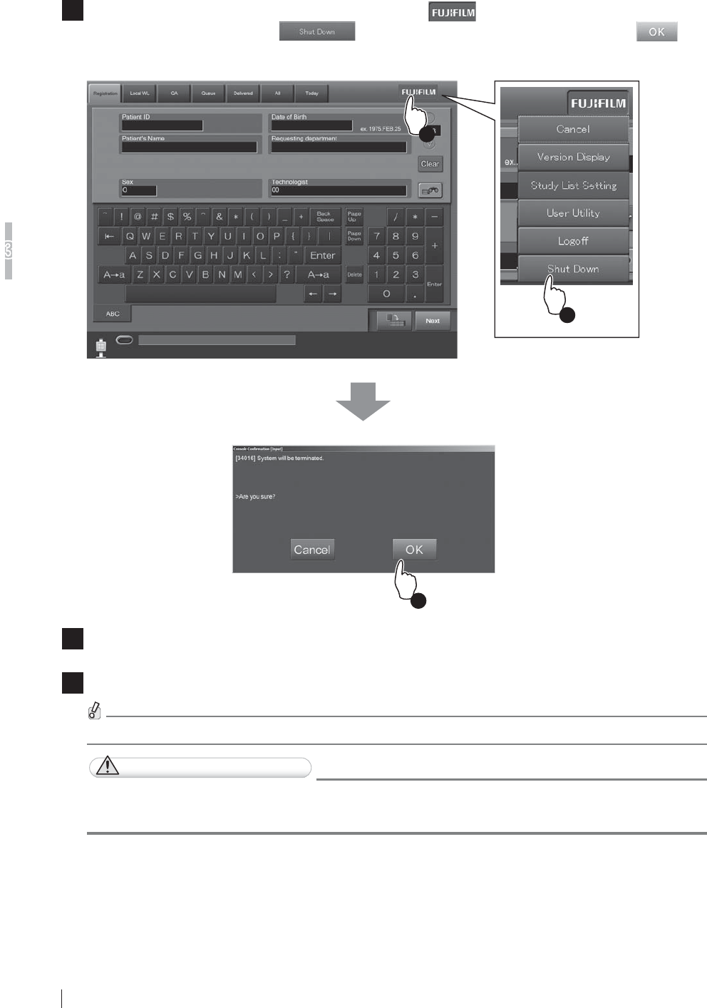
3-8 FDR D-EVO Operation Manual 897N101473E
Basic Operation
3
6KXWWLQJ'RZQWKH6\VWHP
1 &RQ¿UPWKDWWKHHTXLSPHQWLVQRWUXQQLQJ7RXFKWKH EXWWRQDWWKHXSSHUULJKWRIWKH
Console display, and then the button from the displayed menu. Touch the
EXWWRQLQWKHGLVSOD\HGFRQ¿UPDWLRQZLQGRZ
The Console will shut down in a few minutes. The control cabinet will also turn off automatically.
3
2
1
2Turn off the display as necessary.
3 7XUQRIIWKHUDGLRJUDSKLFH[DPLQDWLRQVWDQG
Normally, it is not necessary to turn off the power supply unit.
CAUTIONS
Do not turn off the control cabinet with the main switch.
Shutdown operation may not be performed normally.

3-9
FDR D-EVO Operation Manual 897N101473E
Basic Operation
3
3.3 Routine Operations
FDR D-EVO routine operations can be broadly divided into the following three steps.
Step 1 Entering the Patient Information
Step 2 Selecting the Anatomical Region and Exposure/Study Menu
Step 3 X-ray Exposure
(See page 3-10.)
(See page 3-11.)
(See page 3-13.)
HINT
Operations that are actually performed on the FDR D-EVO are only those described in “ Step 3 X-ray Exposure”. Other
operations are performed on the Console.
For details, see “DR-ID 300CL Operation Manual”.
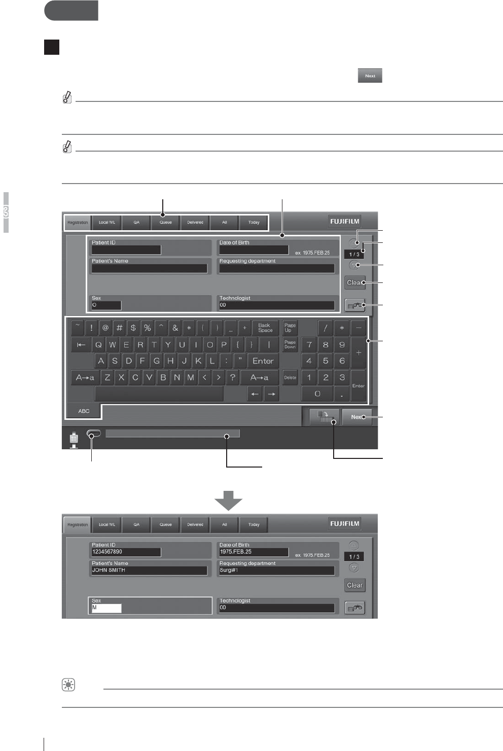
3-10 FDR D-EVO Operation Manual 897N101473E
Basic Operation
3
Step 1 (QWHULQJWKH3DWLHQW,QIRUPDWLRQ
1The Study Information Input Screen below is displayed on the Console display immediately after
startup.
Enter patient information items appropriately, and then touch the button.
Not all the items of patient information need to be input.
Input any one of the items in order to proceed to the next operation.
:KHQWKHRSWLRQDOFDUGUHDGHULVSURYLGHGSDWLHQWLQIRUPDWLRQFDQEHLQSXWE\UHDGLQJIURPD
PDJQHWLFFDUG
List tab
Displays various lists.
Patient information input field
Input patient information.
Shows page number of the
patient information input field.
Turns one page backward.
Turns one page forward.
Clears patient information
(except for technologist).
Operates the Patient Information
Database function to input patient
information.
Touch panel soft keyboard
Used to input characters in the
patient information input field.
Reserves a study.
Terminates patient information input,
and proceeds to exposure menu
selection.
Exposure enable/disable status
Indicates whether exposure is enabled
(lights green) or disabled.
Operating status
Displays the operating status, error messages, and other information.
Patient information includes the following items.
Accession No. / Reception No. / Patient ID / Patient’s Name / Sex / Date of birth / Requesting department code / Requesting
department name / Technologist / Patient comment / Physical disorder information / Infection information / Contraindication
information / Pregnancy / Height (cm) / Weight (kg) / Telephone no. / Outpatient/Inpatient / Blood type (ABO) / Blood type (Rh) /
Comments on study
HINT
You can change patient information input items and their display order in the User Utility settings.
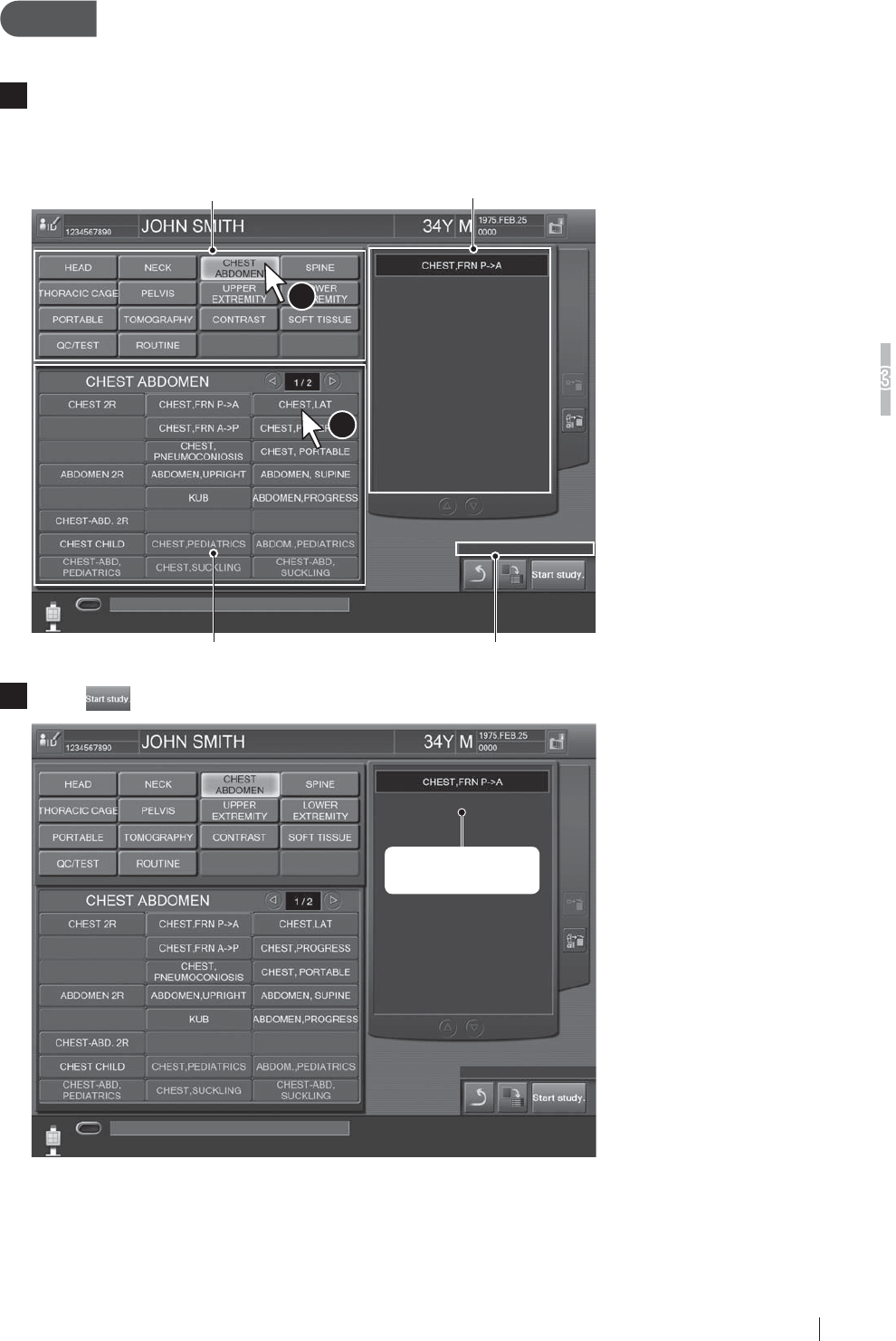
3-11
FDR D-EVO Operation Manual 897N101473E
Basic Operation
3
Step 2 6HOHFWLQJWKH$QDWRPLFDO5HJLRQDQG([SRVXUH6WXG\
Menu
1The Exposure Menu Selection Screen is displayed.
7RXFKDQDQDWRPLFDOUHJLRQWRGLVSOD\WKHGHVLUHGH[SRVXUHPHQXDQGWKHQWRXFKDQH[SRVXUH
menu (more than one menu can be selected). The selected exposure menu(s) is displayed in the
VHOHFWHGH[SRVXUHPHQXOLVWRQWKHULJKWVLGHRIWKHVFUHHQ
1
2
Selected exposure menu listExposure region list
Exposure menu list by region Technologist display field
2Touch DIWHUVHOHFWLQJH[SRVXUHPHQXV
Selected exposure
menus
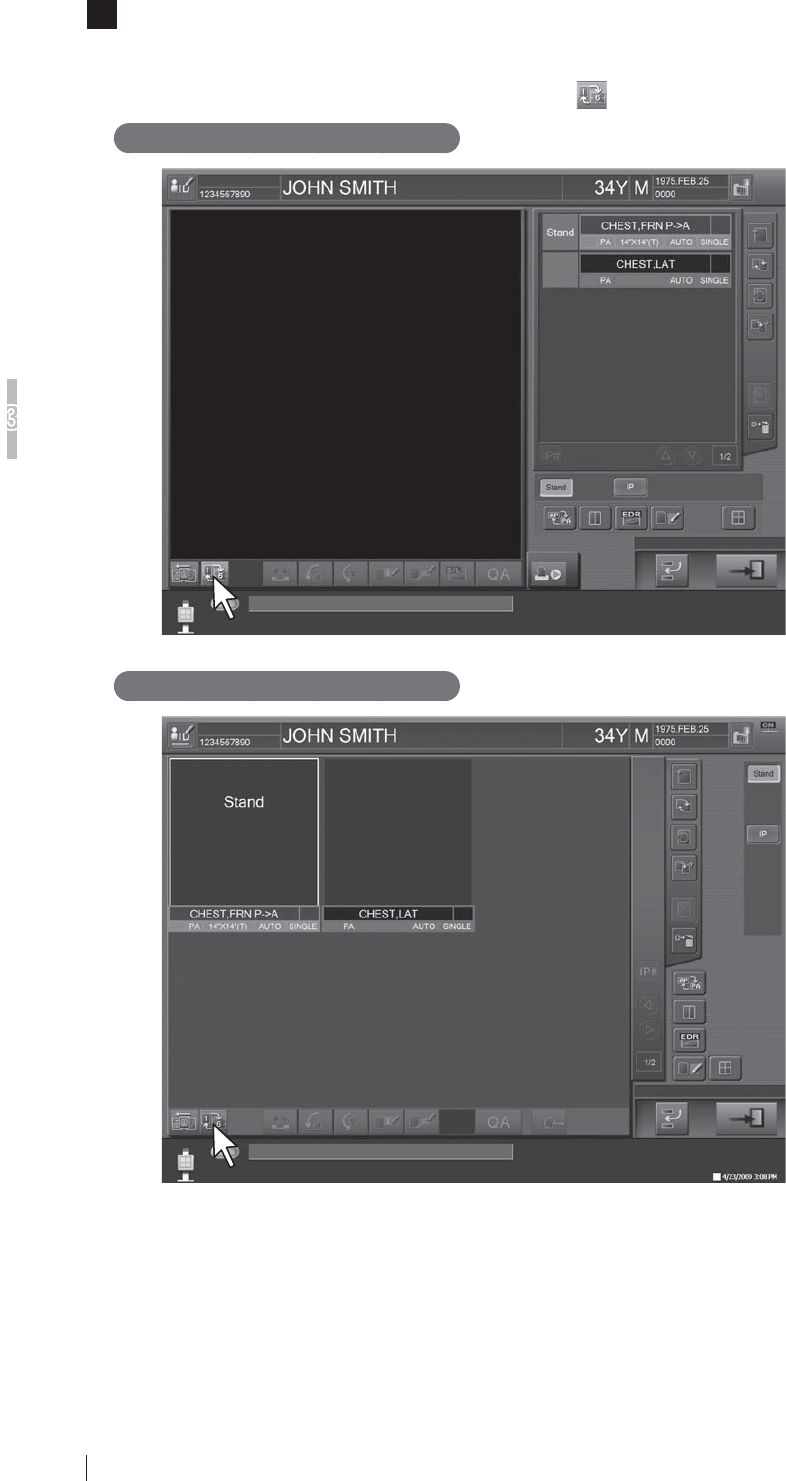
3-12 FDR D-EVO Operation Manual 897N101473E
Basic Operation
3
3The Study Screen is then displayed.
2SHUDWHDSSURSULDWHO\DFFRUGLQJWRGLVSOD\PRGHRQHLPDJHGLVSOD\VL[LPDJHGLVSOD\RQWKH
Study Screen.
7KHPRGHFDQEHVZLWFKHGDOWHUQDWHO\E\WRXFKLQJ .
One-image display mode
Six-image display mode
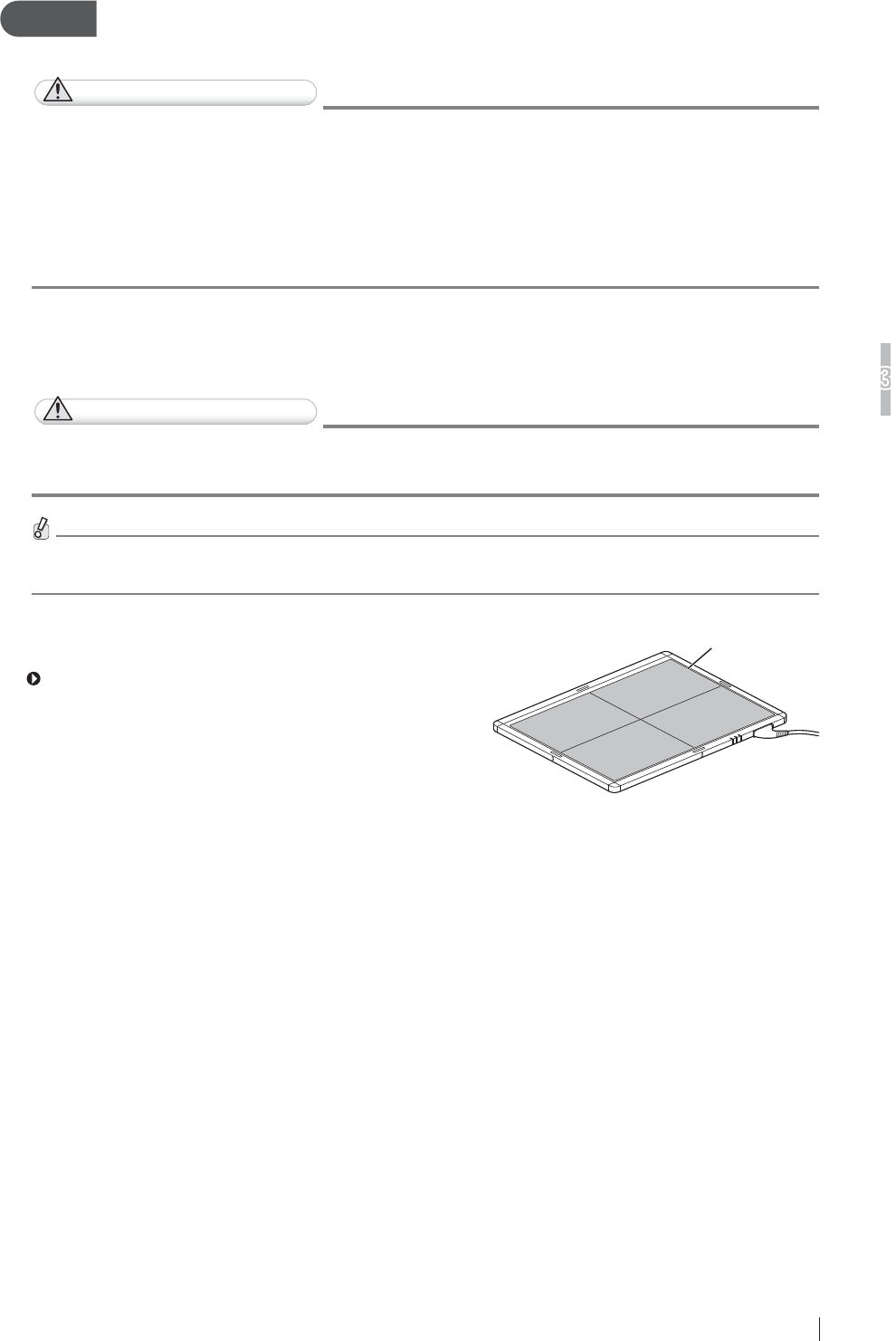
3-13
FDR D-EVO Operation Manual 897N101473E
Basic Operation
3
Step 3 X-ray Exposure
When settings on the Console have been completed, you can perform an exposure.
CAUTIONS
Ɣ 0DNHVXUHWRLGHQWLI\DSDWLHQWDJDLQVWWKHQDPHRUELUWKGDWHDQGWKHQKDYHKLPKHUWDNHD
SURSHUSRVLWLRQLQJIRUH[SRVXUH
Ɣ 0DNHVXUHWRFRQ¿UPWKHH[SRVXUHPHQXWREHXVHGDQGWKHQKDYHDSDWLHQWWDNHDSURSHU
SRVLWLRQLQJIRUH[SRVXUH
Ɣ :KHQPXOWLSOHSDQHOVDUHXVHGPDNHVXUHWKDWWKH5($'<ODPSDPRQJWKHVWDWXVODPSV
RIWKHÀDWSDQHOVHQVRULVOLWLQRUGHUWRFRQ¿UPWKDWLWLVWKHFRUUHFWRQHIRUWKHVHOHFWHG
WHFKQLTXH
>@3RVLWLRQLQJWKHSDWLHQW
Position the patient.
CAUTIONS
([HUFLVHGXHFDUHVRWKDWDQLQWUDYHQRXVOLQHRUGUDLQWXEHSXWWRDSDWLHQWGRHVQRWKRRNLQWR
WKHHTXLSPHQW
)RUWKHH[SRVXUHSRVLWLRQRIWKHXSULJKWW\SHEHGW\SHUDGLRJUDSKLFH[DPLQDWLRQVWDQGVHHLWV
Operation Manual.
:KHQPDNLQJDQH[SRVXUHGLUHFWO\XVLQJWKHÀDWSDQHOVHQVRU
set the exposure position by reference to the effective area.
For details on the effective area, see “Ŷ'5,'38´
(page A-4).
Effective area
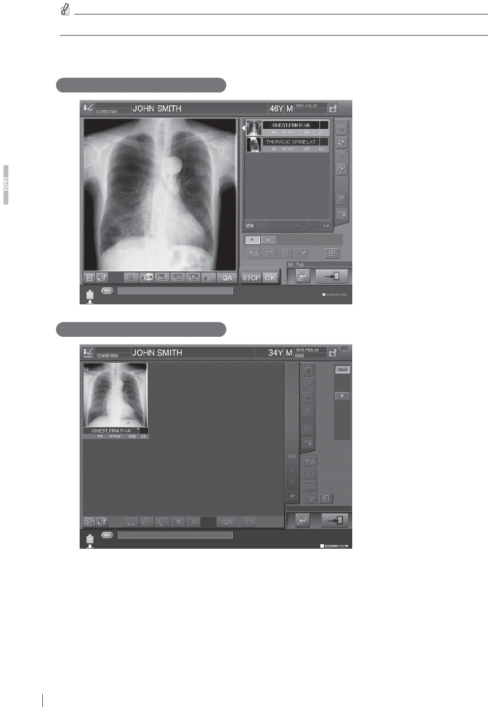
3-14 FDR D-EVO Operation Manual 897N101473E
Basic Operation
3
>@;UD\H[SRVXUH,PDJHGLVSOD\LQJ
0DNHVXUHWKDWH[SRVXUHLVSRVVLEOHRQWKH&RQVROHDQGWKHQSHUIRUP;UD\H[SRVXUH
Perform exposures having the patient hold tight the grip handles if necessary. Exposed images are transferred to the
Console.
One-image display mode
Six-image display mode
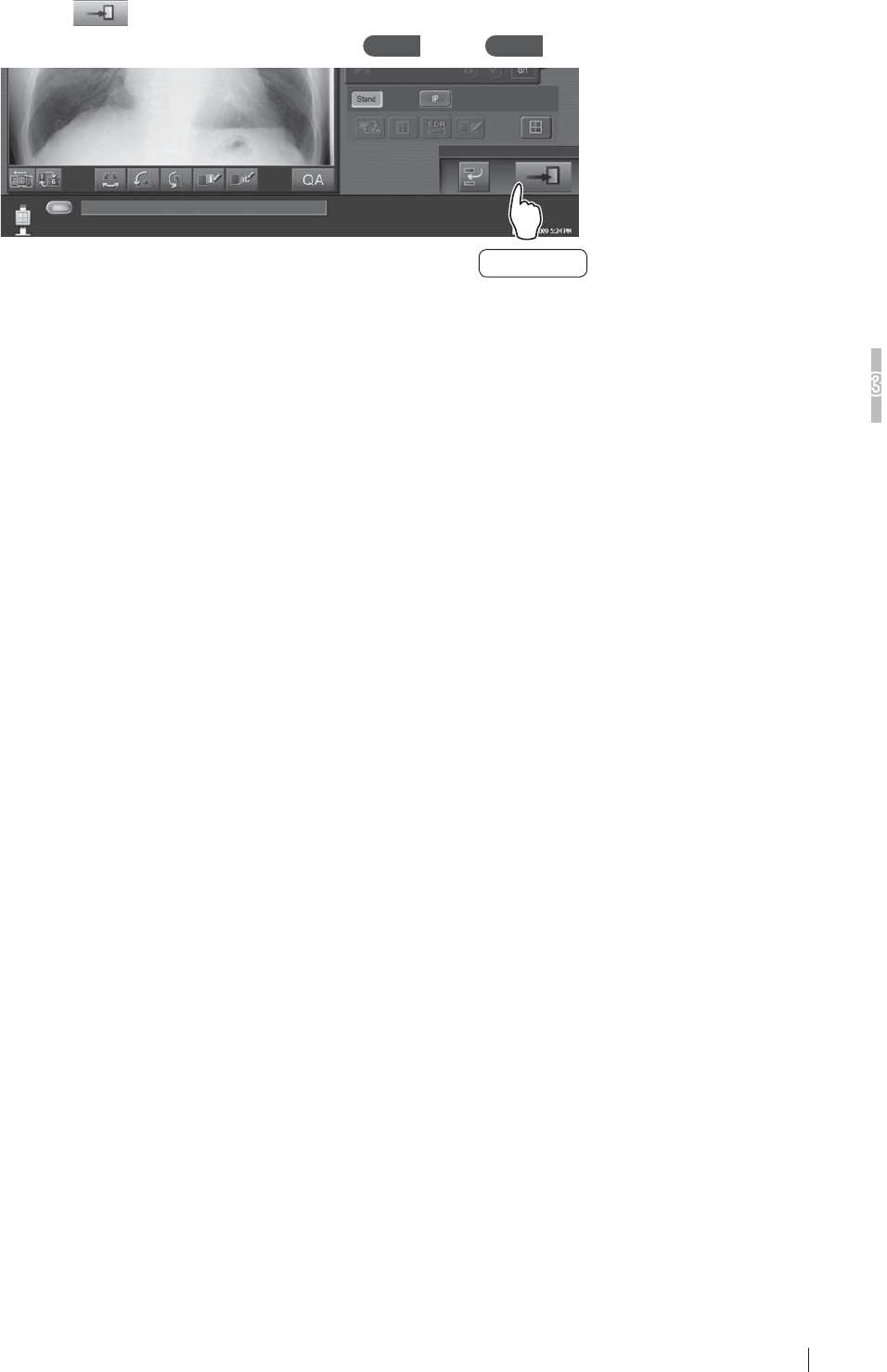
3-15
FDR D-EVO Operation Manual 897N101473E
Basic Operation
3
Touch the button at the lower right to complete the study.
To prepare for exposures of the next patient, repeat Step 1 through Step 3 .
Touch this
button.
The registration of the next new patient should be processed after more than 2 seconds.
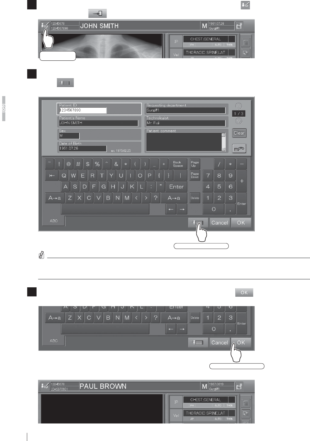
3-16 FDR D-EVO Operation Manual 897N101473E
Basic Operation
3
>@)RUH[SRVXUHVRIWKHQH[WSDWLHQWXVLQJWKHVDPHPHQXV
17RPDNHH[SRVXUHVRIWKHQH[WSDWLHQWXVLQJWKHVDPHPHQXVWRXFKWKH button at the upper
left instead of the button.
Touch this
button.
2The Patient Information Input Screen below appears.
Touch DWWKHORZHUULJKWWRFOHDURIISDWLHQWLQIRUPDWLRQXVHGIRUWKHSUHYLRXVSDWLHQWDQG
then input new patient information items in the same screen.
Touch this button.
:KHQWKHRSWLRQDOFDUGUHDGHULVSURYLGHGSDWLHQWLQIRUPDWLRQFDQEHLQSXWE\UHDGLQJIURPD
PDJQHWLFFDUG
3After patient information for the next patient has been input, touch the button at the lower
ULJKWRIWKHVFUHHQ
Touch this button.
With the exposure/study menus retained as they are, registration of exposure menus completes for the next patient.
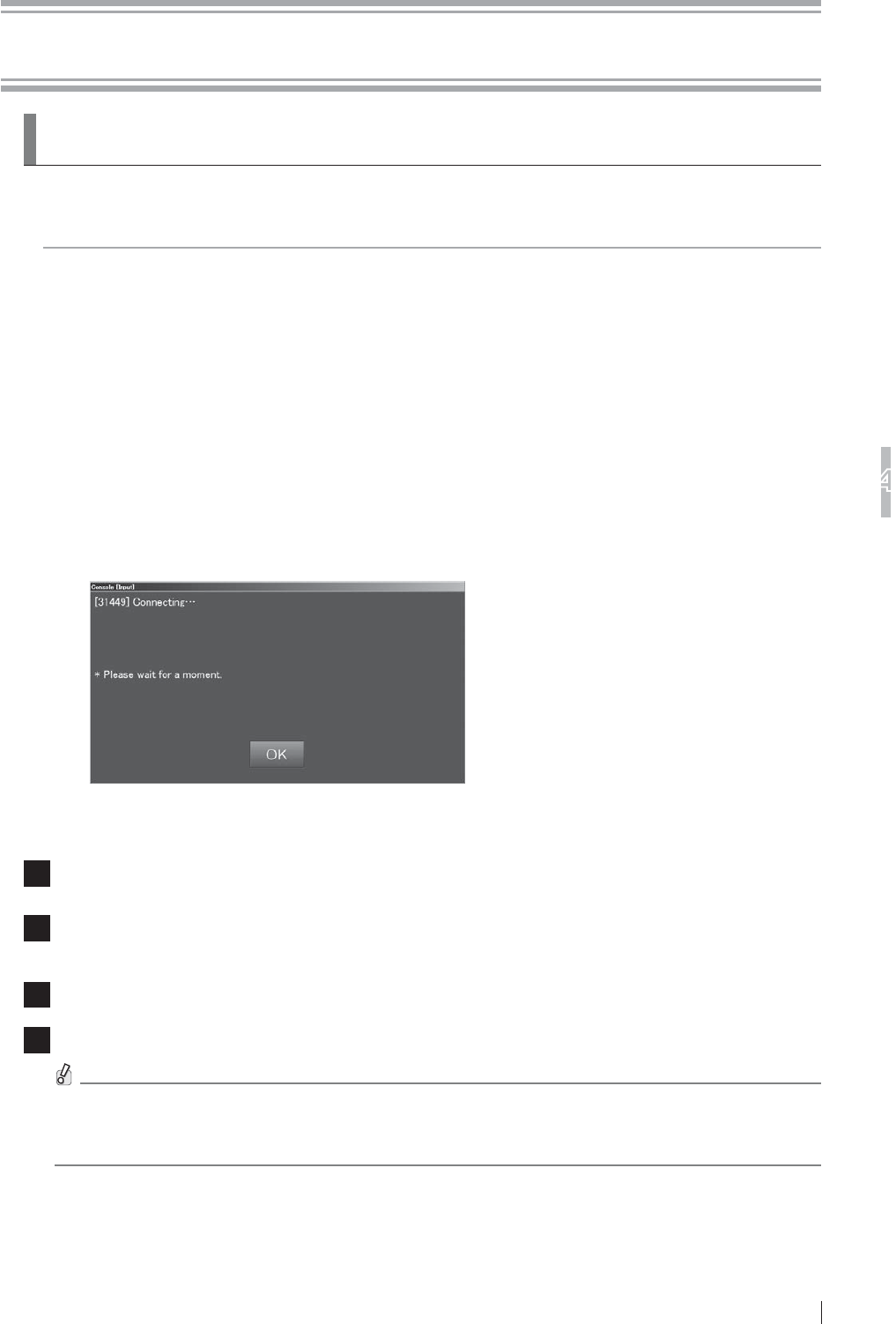
4-1
FDR D-EVO Operation Manual 897N101473E
7URXEOHVKRRWLQJ
4
Chapter 47URXEOHVKRRWLQJ
4.1
:KHQD0HVVDJH$SSHDUVRQWKH&RQVROH
This section describes the warning dialog box and error messages.
If an error which cannot be handled or the same error recurs frequently, contact a FUJIFILM dealer.
If an error of unknown cause occurs, do not continue the operation and contact a FUJIFILM dealer.
>@,IDZDUQLQJGLDORJER[DSSHDUV
If a communication error or an unexpected error has occurred, a warning dialog box pops up on
the screen. In such a case, after checking error details and closing the box, take appropriate action
immediately. Be sure not to continue the operation of the Console without taking an appropriate
action.
If any operation is performed while a warning dialog box is displayed, another screen may be
displayed, hiding the dialog box behind. In this case, press the [Enter] key to close the hidden box.
[2] If a communication error occurs between the Console and
the connected DR system
7KHHUURUPHVVDJHER[,'LVGLVSOD\HGQRWRQO\ZKHQWKH&RQVROHVWDUWVXSEXWDOVRZKHQD
communication error occurs.
When the problem is not solved within a short time after the message box is displayed, perform the
following procedure.
1 6HOHFW>2.@RQWKHPHVVDJHER[
2 &KHFNLIWKHHTXLSPHQWFRQQHFWHGZLWKWKH&RQVROHLVWXUQHGRQ
If any equipment is turned off, turn it on and wait for a while.
3If the problem is not solved, shut down the Console.
4 0DNHVXUHWKDWWKHSRZHUVWDWXV/('RIWKHFRQWUROFDELQHWLVRIIDQGWKHQUHVWDUWWKH&RQVROH
If the power status LED of the control cabinet does not turn off even after approximately
PLQXWHVKDYHSDVVHGIROORZLQJWKHVKXWGRZQRIWKH&RQVROHSUHVVDQGKROGWKHPDLQ
switch of the control cabinet.
When the Console is restarted and the same error message box is displayed, contact a FUJIFILM
dealer.
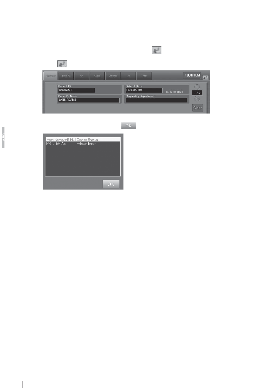
4-2 FDR D-EVO Operation Manual 897N101473E
7URXEOHVKRRWLQJ
4
[3] If an error occurs on the Console
If an error occurs on the Console, an error message box is displayed on the screen.
In such a case, check error details and select [OK] in the box, and then take an appropriate action.
[4] If an error occurs on an output destination device
If an error occurs on an output destination device, is displayed at the upper right of the screen.
In such a case, operate as follows.
Select .
An error display box is displayed.
Check the connection status, select , and then take an appropriate action.
“Error display box“
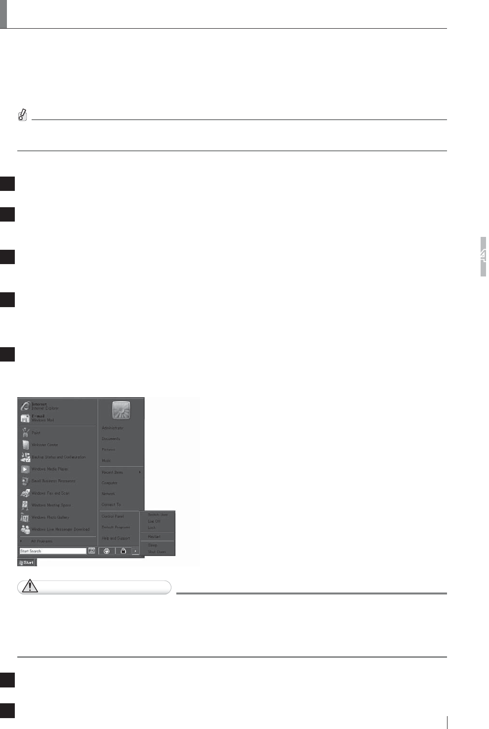
4-3
FDR D-EVO Operation Manual 897N101473E
7URXEOHVKRRWLQJ
4
4.2 How to Cope with an Error...
>@:KHQWKHV\VWHPKDQJVXS
If an inappropriate processing is performed while this equipment is operating, the screen may freeze
and the system may hang up (processing disabled). In that case, shut down the equipment forcibly
according to the following procedure, and then restart it.
,IWKHVFUHHQIUHH]HVDQGDKDQJXSRFFXUVUHPRYHWKHNH\ERDUGDQGPRXVHDQGUHFRQQHFW
them. If this operation does not solve the problem, restart the Console.
1 3UHVVWKH>&WUO@>$OW@>'HO@NH\VVLPXOWDQHRXVO\
2 ³:LQGRZV6HFXULW\´LVGLVSOD\HG
Select [Start Task Manager].
3 ³:LQGRZV7DVN0DQDJHU´LVGLVSOD\HG
Select “IIPMAIN.exe” in the list in the “Processes” tab, and then click [End Process].
4 7KHPHVVDJHER[LVGLVSOD\HG
Click [End Process] to terminate the Console.
Depending on equipment status, an error message may not be displayed.
5 7KHGHVNWRSVFUHHQRIWKHRSHUDWLQJV\VWHP:LQGRZV9LVWDLVGLVSOD\HG
Close the “Windows Task Manager window”, and then select the [Start] button at the lower left of the screen. Select
[Restart] from the displayed menu.
CAUTIONS
Ɣ 0DNHVXUHWRVKXWGRZQWKHV\VWHPIROORZLQJWKHDERYHSURFHGXUHVLQFDVHRIDKDQJXSRI
the Console. If the personal computer is turned off without shutdown, an error may occur on
the computer.
Ɣ 1RWHWKDWIRUFLEOHVKXWGRZQSURFHVVLQJRIWKHHTXLSPHQWLVDQHPHUJHQF\DFWLRQ'RQRWXVH
this action under normal situations.
6Press and hold the main switch of the control cabinet to turn it off.
7Press the OFF side of the main switch of the power supply unit.

4-4 FDR D-EVO Operation Manual 897N101473E
7URXEOHVKRRWLQJ
4
>@:KHQWKH&RQVROHLVWXUQHGRIIGXHWRDQHOHFWULFDORXWDJH
When the Console is turned off due to an electrical outage, etc., take the following actions according
the condition when the power comes back on.
Ŷ ,IWKHSRZHUFRPHVEDFNRQVRRQDIWHUDQHOHFWULFDORXWDJH
Wait until the Console restarts.
When the Console has restarted, shut down the Console by following the normal procedure.
For details of system shutdown, see the “DR-ID 300CL Operation Manual”.
To restart the Console, follow the procedure for the system startup.
>@,IDKDUGGLVNRIWKH&RQVROHLVGDPDJHG
If one of the hard disks is damaged, a window indicating so will appear. In such a case, press the
)NH\DQGFRQWDFWRXURI¿FLDOGHDOHU
>@,IDZKLWHLPDJHLVGLVSOD\HGDIWHUDQH[SRVXUH
If a white image is displayed, a LAN communication error may have occurred.
&KHFNLIWKH/$1FRPPXQLFDWLRQFRQQHFWRUVDUHSURSHUO\FRQQHFWHGEHWZHHQWKHÀDWSDQHOVHQVRU
and the power supply or and between the power supply unit and the control cabinet. Make an
H[SRVXUHDJDLQDIWHUFRQ¿UPDWLRQ
>@3UHFDXWLRQVIRURSHUDWLQJWKHV\VWHPZKHQ³,QLWLDOL]LQJ´RU
³&KDQJLQJ)3'´LVGLVSOD\HGLQWKH&RQVROH¶VRSHUDWLQJ
VWDWXVGLVSOD\DWWKHWLPHRIUHSODFLQJWKHÀDWSDQHOVHQVRU
:KHQUHSODFLQJWKHÀDWSDQHOVHQVRUE\XVLQJWKHPDLQVZLWFKRIWKHSRZHUVXSSO\XQLWRUWKH
optional remote switch, “Initializing” or “Changing FPD” is displayed in the operating status display
of the Console. While either of the status messages is displayed, you cannot register/select
exposure menu(s), change the selector, etc.
Perform the operations above after the status message disappears.
>@,IZLUHOHVVFRPPXQLFDWLRQZLWKWKHÀDWSDQHOVHQVRU'5,'
601SE) is not possible
,IWKHÀDWSDQHOVHQVRULVQRWUHFRJQL]HGLQZLUHOHVVFRPPXQLFDWLRQPRGHFRQQHFWWKHFRQQHFWRUWR
use the system in wired communication mode.
>@,IZLUHOHVVFRPPXQLFDWLRQPRGHLVGLVDEOHGZKHQXVLQJWKH
ÀDWSDQHOVHQVRU'5,'6(
If wireless communication is interrupted, an error message prompting reconnection is displayed
after 30 seconds. Select “Yes”. If connection is not established even after the selection is made,
connect the connector and retry the connection.

5-1
FDR D-EVO Operation Manual 897N101473E
Daily Inspection and Maintenance
5
Chapter 5 Daily Inspection and
Maintenance
5.1
Daily User Inspection and Maintenance
During maintenance and inspection, strictly observe precautions contained in “Chapter 1 For Safe
Operation” in this manual for you to use the FDR D-EVO under best conditions.
5.1.1 Daily Inspection (DR-ID 600)
Inspection Before Use
0DNHVXUHWKDWWKHHTXLSPHQWVWDUWVXSQRUPDOO\
0DNHVXUHWKDWWKHHTXLSPHQWFRPPXQLFDWHVZLWKFRQQHFWHGGHYLFHVQRUPDOO\
0DNHVXUHWKDWWKHWLPHGLVSOD\HGLVFRUUHFW
See “3.2 Starting Up and Shutting Down the System” (page 3-6).
,QVSHFWLRQ'XULQJ8VH
0DNHVXUHWKDWLPDJHVDUHRXWSXWQRUPDOO\
See “3.3 Routine Operations” (page 3-8).
Inspection After Use
0DNHVXUHWKDWWKHSRZHUWXUQVRIIQRUPDOO\E\VKXWWLQJGRZQWKHHTXLSPHQW
See “3.2 Starting Up and Shutting Down the System” (page 3-6).
&OHDQLQJLQVWUXFWLRQV
Use a neutral detergent or ethanol to clean the outer surfaces.
CAUTIONS
Ɣ Do not use a solvent such as thinner or benzine, as it corrodes the outer surfaces.
Ɣ 0DNHVXUHQRWWROHWZDWHUGHWHUJHQWDQGHWKDQROJHWLQVLGHWKHHTXLSPHQW
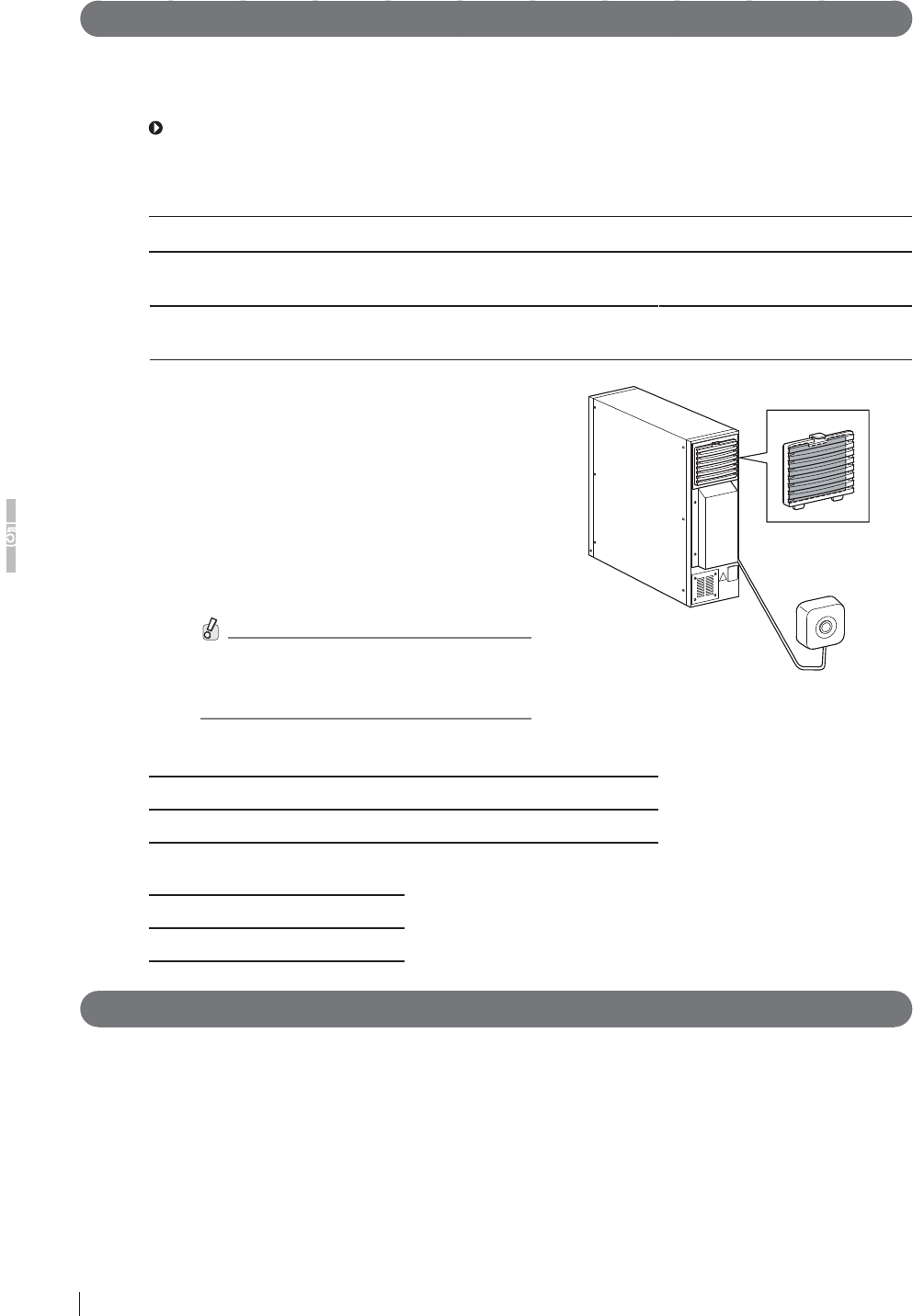
5-2 FDR D-EVO Operation Manual 897N101473E
Daily Inspection and Maintenance
5
5.1.2 Periodical Inspection
Inspection Every Three Months
Using a vacuum cleaner, remove any dirt or dust accumulated in each unit of the equipment once
every three months. Clean then with a slightly moistened soft cloth and wipe off any moisture with a
dry cloth.
See “2.2 Unit Names and the Functions” (page 2-3).
ŶDR-ID 600
DR-ID 600PU
NO. Unit NO. Unit NO. Unit
1Flat panel sensor 2Power supply unit 3Power supply unit
$LU¿OWHU
4Remote switch
(optional)
$LU¿OWHU
&OHDQWKHDLU¿OWHURQWKHUHDURIWKHSRZHU
supply unit with a vacuum cleaner. Push
down the lever at the top of the louver-and-
¿OWHUDVVHPEO\DQGFOHDQWKHDLU¿OWHUZLWKD
vacuum cleaner after detaching it from the
assembly.
Remote switch (optional)
Clean the surface of the remote switch
(optional) with a dry cloth, etc.
%HVXUHWRWXUQRIIWKHHTXLSPHQW
EHIRUHFOHDQLQJWKHDLU¿OWHURUWKH
remote switch (optional).
Air filter
Remote switch
(optional)
DR-ID 600MC
NO. Unit NO. Unit
1Control cabinet 2Periphery of devices
%DWWHU\FKDUJHU2SWLRQDO
NO. Unit
1Battery charger (Optional)
Inspection Every Six Months
Check whether the S value remains unchanged once every six months.
5.1.3 Effective Period of Use
7KHHIIHFWLYHSHULRGVRIXVHRIWKHÀDWSDQHOVHQVRUV'5,'6(DQG'5,'6(DQGWKH
power supply unit “DR-ID 600MP” are 6 years, as far as precautions in using them are strictly
observed and regular maintenance and inspection are properly performed.
>$FFRUGLQJWRVHOIFHUWL¿HGGDWDE\)8-,),/0&RUSRUDWLRQ@
The control cabinet DR-ID 600MC and the image processing unit DR-ID 300CL are general-
purpose PCs. Their effective periods of use are described in the operation manuals provided by the
manufacturers.

A-1
FDR D-EVO Operation Manual 897N101473E
Appendix A Specifications
Appendix A Specifications
A.1 Specifications
6SHFL¿FDWLRQVRIWKH)'5'(92DUHVKRZQEHORZ
$ 3URFHVVLQJ&DSDFLW\'5,'
Ŷ 5RXWLQHSURFHVVLQJZKHQWKHWZRLPDJHRXWSXWIRUPDWLVXVHGLQ
standard mode)
(1) Exposure interval
The exposure interval of the FDR D-EVO is at least 8 seconds.
However, the interval varies depending on the region, the load to network communication, etc.
$ ,PDJH2XWSXW'5,'
Ŷ 6WDQGDUGSURFHVVLQJ
(1) Film output
Connection to the Imager makes it possible to obtain hard copies at the image reduction ratios
and in the formats below.
Ɣ)RUVWDQGDUGSL[HOGHQVLW\LPDJHV
Output size Reduction ratio
7ZRLPDJHRXWSXW 2QHLPDJHRXWSXW
14” × 17” (35 × 43cm) 61% 100%
14” × 14” (35 × 35cm) 61% 100%
10” ×12” 85% 100%
8” × 10” 100% 100%
18 × 43cm 100% 100%
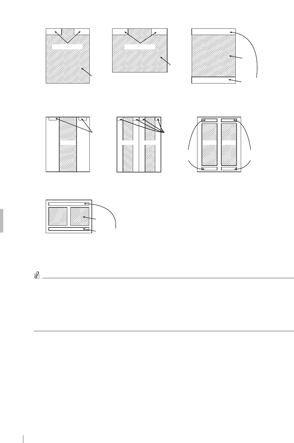
A-2 FDR D-EVO Operation Manual 897N101473E
Appendix A Specifications
[Fig. A.1]
(a) 14” × 17” (b) 17” × 14” (c) 14” × 14”
one-image output one-image output one-image output
(14” × 17” film) (14” × 17” film)
(14” × 17” film)
ID information
Image
Image
ID information
ID information
Image
(d) 18 × 43cm (e) 18 × 43cm (f) 18 × 43cm
one-image output two-image output two-image output
(14” × 17” film)
ID
information
ID
information
ID
information
ID
information
(26 × 36cm film)(26 × 36cm film)
ImageImageImage
ImageImage
(g) Two-image output
ID information
Image
(26 × 36cm film)
For one-image output using 17” × 14”, 14” × 17”, 14” × 14” or 18 × 43cm, images are output on 14”
î´¿OP,QRWKHUFDVHVLPDJHVDUHRXWSXWRQîFP¿OP
'HSHQGLQJRQWKHSULQWHUFRQQHFWHGRU&RQVROHVRIWZDUHYHUVLRQXVHGLPDJHRXWSXWVLQWKH
IROORZLQJIRUPDWVDUHDYDLODEOH
Ɣ VL]HRXWSXWRI´î´LPDJHRQ´î´¿OP
Ɣ VL]HRXWSXWRI´î´LPDJHRQ´î´¿OPDVZHOODVUHGXFHGLPDJHRXWSXWRQ
¿OPVRIRWKHUVL]HV
Ɣ VL]HRXWSXWRI´î´LPDJHRQ´î´¿OP

A-3
FDR D-EVO Operation Manual 897N101473E
Appendix A Specifications
$ 5HGXFHG(TXLYDOHQW'5,'
3HDNUHGXFHGHTXLYDOHQWRQWKHIURQWSDQHORIWKHÀDWSDQHOVHQVRUPP$O
A.1.4 Power Supply Conditions
ŶDR-ID 600PU
5DWHGYROWDJH9a
,QSXWFXUUHQW $
)UHTXHQF\ +]
ŶDR-ID 600MC*
5DWHGYROWDJH9a
,QSXWFXUUHQW $
)UHTXHQF\ +]
* Since the DR-ID 600MC is general-purpose electrical equipment, the electric rating above is an example.
A.1.5 Environmental Conditions
ŶDR-ID 600PU
2SHUDWLQJ&RQGLWLRQV
7HPSHUDWXUH &5+&5+
+XPLGLW\ 5+&5+&QRGHZFRQGHQVDWLRQ
$WPRVSKHULFSUHVVXUHK3DK3D
1RQRSHUDWLQJ&RQGLWLRQV
(Environmental conditions under which power can be supplied)
7HPSHUDWXUH &&QRGHZFRQGHQVDWLRQ
+XPLGLW\ 5+5+QRGHZFRQGHQVDWLRQ
$WPRVSKHULFSUHVVXUHK3DK3D
ŶDR-ID 600MC
2SHUDWLQJ&RQGLWLRQV
7HPSHUDWXUH &&
+XPLGLW\ 5+5+QRGHZFRQGHQVDWLRQ
$WPRVSKHULFSUHVVXUHK3DK3D
1RQRSHUDWLQJ&RQGLWLRQV
(Environmental conditions under which power can be supplied)
7HPSHUDWXUH &&
+XPLGLW\ 5+5+QRGHZFRQGHQVDWLRQ
$WPRVSKHULFSUHVVXUHK3DK3D
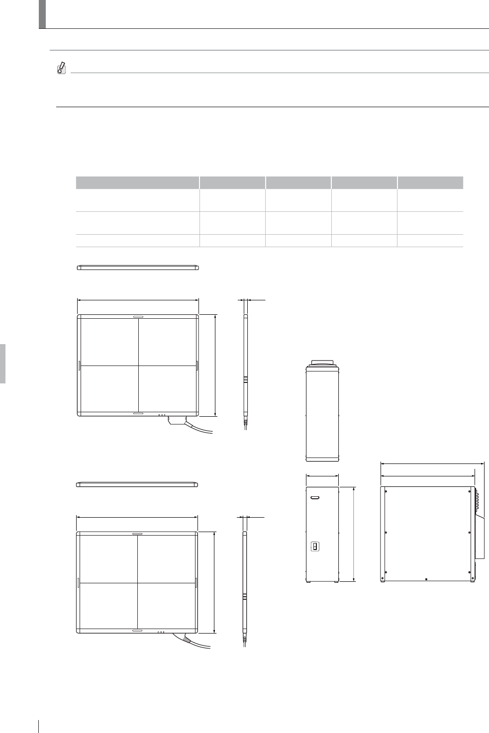
A-4 FDR D-EVO Operation Manual 897N101473E
Appendix A Specifications
$ ([WHUQDO9LHZDQG:HLJKW
The external view and weight of the FDR D-EVO are shown below.
6SHFL¿FDWLRQVGLPHQVLRQVDQGZHLJKWDUHVXEMHFWWRFKDQJHIRULPSURYHPHQWZLWKRXWSULRU
notice.
A.2.1 DR-ID 600
ŶDR-ID 600PU
Width (mm) Depth (mm) +HLJKWPP :HLJKWNJ
Flat panel sensor
(DR-ID 601SE) 460 384 14 Approx. 3.1kg
Flat panel sensor
(DR-ID 600SE) 460 384 14 Approx. 2.8kg
Power supply unit 120 350 (385) 350 Approx. 7.8kg
14460
384
Flat panel sensor
(DR-ID 600SE)
14460
384
Flat panel sensor
(DR-ID 601SE) (385)
350
120
350
Power supply unit
8QLWPP
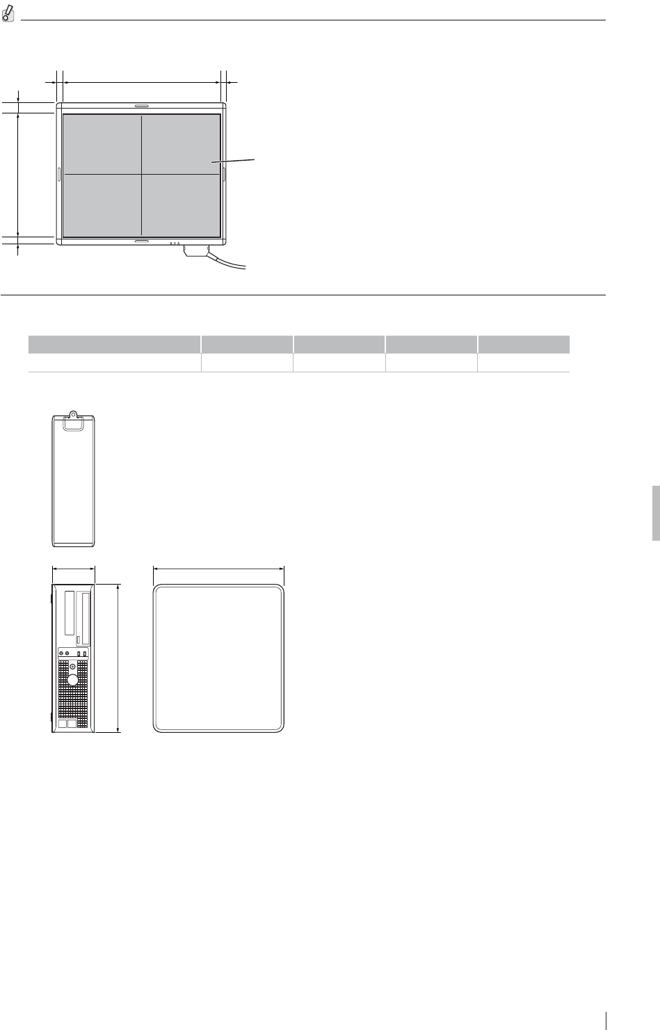
A-5
FDR D-EVO Operation Manual 897N101473E
Appendix A Specifications
7KHHIIHFWLYHDUHDRIWKHÀDWSDQHOVHQVRULVDVVKRZQLQWKH¿JXUHEHORZ
Effective area
432.0 10.7516.75
21.4516.45 345.6
ŶDR-ID 600MC
Width (mm) Depth (mm) +HLJKWPP :HLJKWNJ
Control cabinet 114 353 399 Approx. 8.3kg
353114
399
Control cabinet
8QLWPP
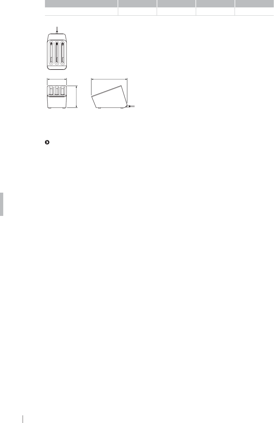
A-6 FDR D-EVO Operation Manual 897N101473E
Appendix A Specifications
Ŷ %DWWHU\FKDUJHU
Width (mm) Depth (mm) +HLJKWPP :HLJKWNJ
Battery charger 120.2 219.8 136.2 Approx. xx kg
Battery charger
8QLWPP
219.8120.2
136.2
ŶDR-ID 300CL
For the external view and weight of the DR-ID 300CL, see the “DR-ID 300CL Operation Manual”.

Z-1
FDR D-EVO Operation Manual 897N101473E
Appendix Z Precautions for Exposure
Appendix Z
Precautions for Exposure
Z1.
Precautions for Exposure in AUTO MODE
In AUTO MODE, stable image output can be obtained by means of the following.
5DGLDWLRQ¿HOG
(2) EDR image data analysis
(3) Detailed depiction of the cervical region
However, problems may arise due to differences in the multiple diaphragms or scattered rays of the
X-ray equipment. For such problems, contact a FUJIFILM dealer and use other recording modes, such
as SEMI-AUTO MODE or FIX MODE.
Z.1.1 Radiation Field
1'RQRWVHWWKHUDGLDWLRQ¿HOGH[WUHPHO\VPDOO%HVXUHWRVXEMHFWRQHWKLUGRUPRUHRIWKHOHQJWKRI
each side of the bucky of the DR system to X-ray exposure.
20DNHVXUHWKDWQRQHRIWKHVLGHVRIWKHUDGLDWLRQ¿HOGRYHUODSZLWKWKHFRQWUDVWPHGLXP(UURUVZLOO
result if they overlap.
$YDLODEOHIRU(DFK$QDWRPLFDO5HJLRQ0HWKRG
Plain Contrast Medium 7RPRJUDSK\
Head 444
1HFN 44–
Chest 4 4 (1 for esophagus) –
Abdomen 4 4 (1 for stomach and intestines) –
Pelvis 44–
3Notes on PRIEF
[PRIEF 4] Used, with some exceptions, for both plain and contrast medium exposure menus,
from the head to the pelvis.
The diaphragm shape will be any convex polygon, including rectangles, circles,
ellipses, tracks, etc.
[PRIEF 1] Used with esophagus, stomach and intestines contrast medium menus.
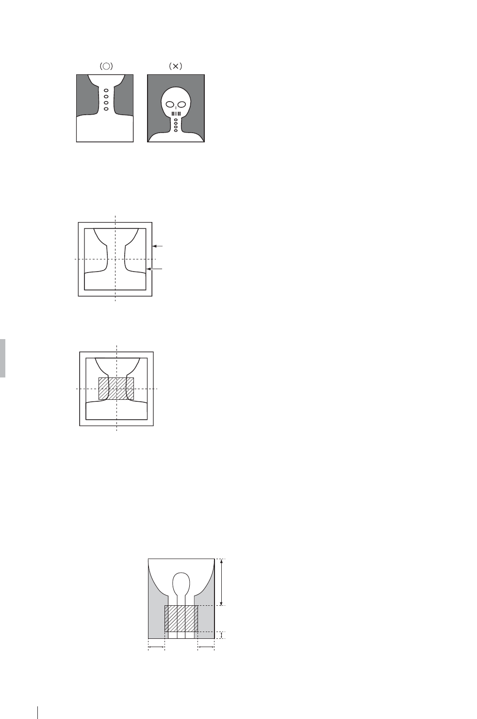
Z-2 FDR D-EVO Operation Manual 897N101473E
Appendix Z Precautions for Exposure
= 'HSLFWLRQRIWKH&HUYLFDO5HJLRQ
17KHUDGLDWLRQ¿HOGPXVWQRWLQFOXGHWKHZKROHKHDG%HVXUHWRVHFXUHWUDQVSDUHQWSRUWLRQVRQERWK
sides of the neck.
8VHWKH³+HDG´PHQXWRLQFOXGHWKHZKROHKHDGLQWKHUDGLDWLRQ¿HOG
2)RUH[SRVXUHRIWKHSKDU\Q[RUODU\Q[EHVXUHWKDWWKHQHFNFRPHVWRWKHFHQWHURIWKHUDGLDWLRQ¿HOG
so that the frontal and lateral orientations can be recognized appropriately.
Image area
Radiation field
3In pharynx and/or larynx exposure, do not use lead characters in the oblique line section.
Z.1.3 Depiction of the HIP JOINT AXL – 2 Menu
1Make sure to position the region of interest within the slanted-line area shown below.
Do not collimate further inside.
2Positioning should be done so that the condyle and the femur run along the longer edge. (Do not
position them against the shorter edge.)
7/12
1/12
1/41/4
Condyle side
Femur side

Z-3
FDR D-EVO Operation Manual 897N101473E
Appendix Z Precautions for Exposure
= ('5,PDJH'DWD$QDO\VLV
1Image unevenness appearing when the grid used in exposure is not positioned correctly in terms of
the bulb, when there are shadows from clothing, or when X-ray radiation of the X-ray exposure area is
uneven is a problem that arises during EDR image data analysis, which cause unstable density on the
image.
Avoid such unevenness in the X-ray exposure area as far as possible.
2If the target includes such materials as gypsum, denture, etc., stable density may not be obtained,
EHFDXVHVXFKPDWHULDOVPDNHLWGLI¿FXOWWRDQDO\]H('5LPDJHGDWD
In such cases, use S-Shift/C-Shift or FIX MODE.
3The EDR performs processing for the image area trimmed by the DR system.
:KHQXVLQJOHDGFKDUDFWHUVRUPHWDOVIRUPHDVXUHPHQWSODFHWKHPLQVLGHWKHUDGLDWLRQ¿HOGDQG
then make an exposure.
4Precautions when using AUTO MODE.
Auto mode Precautions
IAs this mode is available for extracting information on the skin, secure the positioning so
that the direct X-rays are incident to an area other than the target.
II No special precautions.
III Be sure to use a Ba contrast medium.
IV
1 Be sure to secure the positioning so that the X-rays are incident to the area directly
outside the target.
$VWKHUHDGLQJODWLWXGHLV¿[HGLWLVQHFHVVDU\WRFRQWUROWKHWXEHYROWDJHDFFRUGLQJWRWKH
thickness of the target, as usual.
V$VWKHUHDGLQJODWLWXGHLV¿[HGLWLVQHFHVVDU\WRFRQWUROWKHWXEHYROWDJHDFFRUGLQJWRWKH
thickness of the target, as usual.
VI No special precautions.
VII No special precautions.
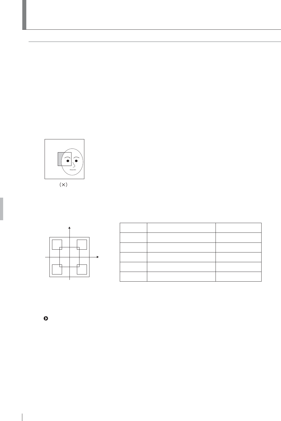
Z-4 FDR D-EVO Operation Manual 897N101473E
Appendix Z Precautions for Exposure
Z.2 Precautions for Exposure in SEMI-
AUTO MODE
These precautions are common to Semi I, II, III and III(**).
1Position the portion you need to display often in the center areas (10cm × 10cm (Semi I), 7cm ×
7cm (Semi II), 5cm × 5cm (Semi III)) of the images trimmed by the DR system.
Position the portion you need to display often in each of the 5cm × 5cm center areas of the half-split
images (both upper and lower halves and right and left halves) and quarter-split image trimmed by
the DR system.
2Never position anything other than the subject in the aforementioned areas. If anything other than
the subject is positioned in such areas, the image density will become lower.
,QDGGLWLRQGRQRWSRVLWLRQDQ\PHWDOVRUDUWL¿FLDOERQHVLQVXFKDUHDV7KHLPDJHGHQVLW\ZLOO
become higher if such objects are positioned in these areas.
3It is necessary to control tube voltage according to subject thickness, as usual.
The following precautions should be observed for Semi IV.
a
bc
de
y
x
Area Center Coordinate (x:y) cm Size (cm)
a(0, 0) 10×10
b(-5, 7) 6×6
c(5, 7) 6×6
d(-5, -7) 6×6
e(5, -7) 6×6
'RQRWSRVLWLRQWUDQVSDUHQWSRUWLRQVDUHDVRWKHUWKDQWKHVXEMHFWLQWKHDIRUHPHQWLRQHG¿YH
areas.
(2) It is necessary to control tube voltage according to subject thickness, as usual.
For details of the menus preset in SEMI-AUTO MODE, see the “DR-ID 300CL Operation Manual”
and “DR-ID 300CL Image Processing Parameters Operation Manual”.

Z-5
FDR D-EVO Operation Manual 897N101473E
Appendix Z Precautions for Exposure
Z.3 Precautions for Exposure in SEMI-X
MODE
The user will select one of the nine areas of the image trimmed by the DR system, on which SEMI-
AUTO MODE applies. (See the illustration below.)
The same precautions as for SEMI-AUTO MODE apply.
LCR
T
M
B
5cm 5cm

Z-6 FDR D-EVO Operation Manual 897N101473E
Appendix Z Precautions for Exposure
Z.4 Precautions for Exposure in FIX MODE
$VUHDGLQJFRQGLWLRQVDUH¿[HGH[SRVXUHFRQGLWLRQVPXVWEHFRQWUROOHGLQWKHVDPHZD\DVIRU
conventional X-ray exposure.
The reading conditions (sensitivity and latitude) have been preset according to the relevant menu in
FIX MODE. Select the exposure conditions which correspond to that menu accordingly.

Z-7
FDR D-EVO Operation Manual 897N101473E
Appendix Z Precautions for Exposure
Z.5 Other Precautions
Z.5.1 Precautions for Exposure of a Subject in Relatively
/DUJH&RQWUDVW
1Exposures using a contrast medium may cause artifacts around it.
2When exposing a subject with any metal objects implanted, artifacts may appear around them.
3For exposures with objects of large X-ray absorption, such as lead characters and metals for
measurement, artifacts may appear around them. Place such objects outside a subject.
Z.5.2 Precautions for DR System
*HQHUDOO\ZKHQSHUIRUPLQJDKLJKVHQVLWLYLW\H[SRVXUHVKRUWO\DIWHUDQH[SRVXUHWKDWWKHÀDW
panel sensor excessively receives direct X-ray, the output image may contain image lags of the
previous exposure. This phenomenon rarely occurs and does not occur insofar as normal sensitivity
exposures are performed.
Exposures at longer intervals can reduce occurrences of this phenomenon. Also observe
precautions as follows.
&RQWLQXRXVKLJKVHQVLWLYLW\H[SRVXUHVWRYHUWHEUDOERG\SDUWFKHVWOXPEDUVSLQHVKRXOGEH
performed at longer intervals than normal exposures.
$KLJKVHQVLWLYLW\H[SRVXUHVKRUWO\DIWHUDKLJKGRVHH[SRVXUHVKRXOGEHSHUIRUPHGDWVXI¿FLHQWO\
long interval.
:KHQSHUIRUPLQJKLJKGRVHH[SRVXUHVUHSHDWHGO\GRQRWXVHFROOLPDWLRQRIWKHUDGLDWLRQ¿HOG
lead characters or metals for measurement at the same position.
= 3UHFDXWLRQVIRU$VVXULQJWKH5DGLDWLRQ)LHOG
CAUTIONS
,WLVLPSRUWDQWWRUHDGWKHIROORZLQJEHIRUHXVLQJWKH)'5'(92GLJLWDOGHWHFWRUFOLQLFDOO\
The FDR D-EVO is a digital X-ray detector designed for use both within and outside of a standard
UDGLRJUDSKLFEXFN\7KH)'5'(92PD\EHH[SRVHGWRDQ\¿HOGVL]HXSWRDQGLQFOXGLQJ´
17” (35 FP)'5'(92PD\EHXVHGLQDQ\VLWXDWLRQZKHUHD¿OPFDVVHWWHPD\EHXVHG
The collimator will open to the full 14” 17” (35 43cm) size when the FDR D-EVO cassette is
inserted in the bucky tray of X-ray systems with positive beam limitation (PBL).
)ROORZWKH;UD\V\VWHPPDQXIDFWXUHU¶VLQVWUXFWLRQVWRDVVXUHWKHLQGLFDWHG¿HOGVL]HPDWFKHVDQG
GRHVQRWH[FHHGWKHDFWXDOUDGLDWLRQ¿HOGVL]HIRUWKHDYDLODEOHUDQJHRI6,'V
Z.5.4 Precautions Related to the X-ray Exposure Time
The X-ray exposure time can be set within the range of 500msec to 3800msec at the time of
installation.

Z-8 FDR D-EVO Operation Manual 897N101473E
Appendix Z Precautions for Exposure
= ,PDJHV2XWSXW:KHQWKH;UD\6KRW6ZLWFKLV2SHUDWHG
Incorrectly
In case that you press the X-ray shot switch only momentarily after selecting exposure menus,
VXI¿FLHQW;UD\GRVHPD\QRWEHDFKLHYHG7KHRXWSXWLPDJHFRQWDLQVLPDJHODJVRIWKHSUHYLRXV
exposure occasionally.
If this happens, select exposure menus again, and then make an exposure.
= 3UHFDXWLRQVIRU8UJHQW8VH
When you start a study before completion of the calibration at the time of startup, the operation will
be in Urgent Use Mode. “Urgent Use is possible” message will appear.
7KHUHLVQRJXDUDQWHHWKDWWKHLPDJHWDNHQLQ8UJHQW8VH0RGHFDQEHXVHGIRUGLDJQRVWLF
purposes. Vertical artifact could appear in the image, if the temperature difference is large from
the previous shutdown of the system. Check the image quality before use.
0RYHIURPWKH6WXG\6FUHHQWRWKH3DWLHQW,QIRUPDWLRQ,QSXW6FUHHQLPPHGLDWHO\DIWHUH[LWLQJ
Urgent Use Mode, so that the calibration will start over automatically.
Z.5.7 Precautions Related to Continuous Operation
If you plan to continuously run the system for over 24 hours, perform post-operation check, and
then restart the system.
Otherwise, calibration will not be performed normally, and image quality cannot be guaranteed as a
result.
Z.5.8 Precautions Related to Grid
Depending on the type of the grid used, its stripes may appear in the image after making an
exposure. To avoid such moire effects, sway the grid from side to side, or use the Grid Pattern
Removal Processing Software in conjunction with the grid with 40 lines.

O-1
FDR D-EVO Operation Manual 897N101473E
Appendix O Use of Optional Items
Appendix O Use of Optional Items
O.1 Optional Items
Name Description
Remote switch $VZLWFKFDEOHXVHGIRUWHPSRUDULO\GLVFRQQHFWLQJWKHSRZHUWRWKHÀDWSDQHO
sensor in order to connect/disconnect its connector while the system is in
operation. Up to two remote switches can be connected.
Using this switch reduces the time required for normal insertion/removal
procedure.
For the external view, see “O.2.1 Remote Switch” (page O-2).
Relay cable A relay cable used for branching the cable for two remote switches, when
each of them is attached to the upright-type and bed-type radiographic
examination stands.
For the external view, see “O.2.2 Relay Cable” (page O-2).
SE storage case $FDVHXVHGIRUFDUU\LQJDQGVWRULQJWKHÀDWSDQHOVHQVRU
For the external view and precautions, see “O.3 Using the SE Storage
Case” (page O-3).
DAP connector cable A cable used for connecting a dose-area product (DAP) meter.
For the external view and precautions, see “O.4 Using the DAP Connector
Cable” (page O-4).
Retaining bracket for MP $VHWRIDQDQFKRUDQGD¿[WXUHZKLFKLVXVHGIRUVHFXULQJWKHSRZHUVXSSO\
XQLWWRWKHÀRRU
For the external view, see “O.5 Using the Retaining bracket for MP” (page
O-5).
&RQQHFWLRQFDEOHIRUWKHÀDW
panel sensor (power supply unit)
$FDEOHWKDWFRQQHFWVWKHÀDWSDQHOVHQVRUDQGWKHSRZHUVXSSO\XQLW
7KLVFDEOHLVXVHGIRUDGGLQJWKHVHFRQGÀDWSDQHOVHQVRUFKDQJLQJRYHUWKH
FRQQHFWLRQEHWZHHQWKHÀDWSDQHOVHQVRUVDQGRWKHUXVDJHV
Connection cable for X-ray
equipment (9 cores)
A signal cable that connects the power supply unit and the X-ray equipment
(Xcon). Two types are available.
&DEOHOHQJWKPDQGP
Connection cable for X-ray
equipment (3 cores)
A signal cable for high current application, which connects the power supply
unit and the X-ray equipment (Xcon). Two types are available.
&DEOHOHQJWKPDQGP
Communication cable for X-ray
equipment and power supply
unit (RS232C cable)
A communication cable that connects the power supply unit and the X-ray
equipment (Xcon). This cable is used for setting the tube voltage and mAs via
communication. Four types are available.
&DEOHOHQJWKPSLQV
&DEOHOHQJWKPSLQV
&DEOHOHQJWKPSLQV
&DEOHOHQJWKPSLQV
Relay unit for AC bucky A relay unit consisting of the relay and terminal block for the AC bucky. Four
W\SHVDUHDYDLODEOH
For 100V, 120V, 200V, and 220V
0DJQHWLFFODPSIRUÀDWSDQHO
sensor cable
$FODPSIRU¿[LQJWKH6(FDEOHWRWKHUDGLRJUDSKLFH[DPLQDWLRQVWDQGHWF
Cassette holder $FDVVHWWHKROGHUDWWDFKHGWRWKHÀDWSDQHOVHQVRUIRULPSURYLQJWKHORDG
EHDULQJFDSDFLW\RIWKHÀDWSDQHOVHQVRUZKHQPDNLQJDQH[SRVXUHGLUHFWO\
with it.
Battery pack $EDWWHU\SDFNIRUWKHÀDWSDQHOVHQVRU'5,'6(XVHGLQZLUHOHVV
communication mode.
Battery charger A battery charger for the battery pack.
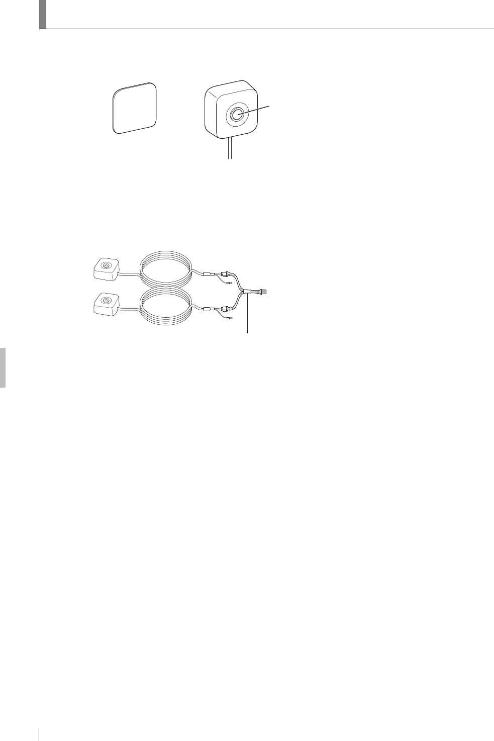
O-2 FDR D-EVO Operation Manual 897N101473E
Appendix O Use of Optional Items
28VLQJWKH5HPRWH6ZLWFK
O.2.1 Remote Switch
Remote switch
Operation button
Remote switch fixture*
(with double-sided tape)
*
7KLVPHWDO¿[WXUHLVXVHGZKHQWKHUHPRWHVZLWFKFDQQRWEHDWWDFKHGWRDZDOOHWFZLWKWKHPDJQHWRQWKHEDFN
7KHUHPRWHVZLWFK¿[WXUHLVDWWDFKHGWRDZDOOHWFZLWKGRXEOHVLGHGWDSH
O.2.2 Relay Cable
Relay cable
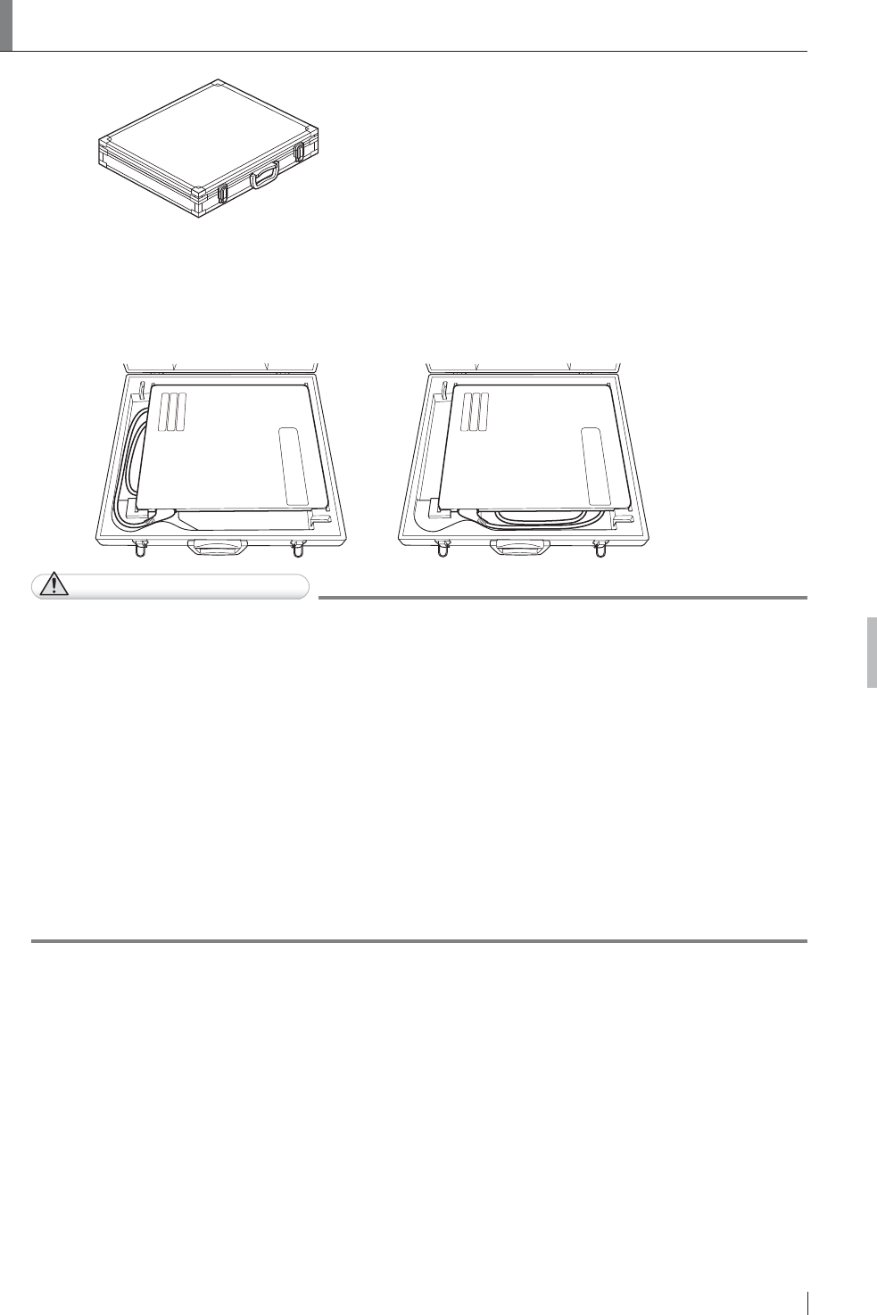
O-3
FDR D-EVO Operation Manual 897N101473E
Appendix O Use of Optional Items
28VLQJWKH6(6WRUDJH&DVH
SE storage case
:KHQVWRULQJWKHÀDWSDQHOVHQVRULQWKH6(VWRUDJHFDVHSODFHLWZLWKWKHH[SRVXUHSODQHGRZQ
1RWHDOVRWKDWWKHVWRUDJHPHWKRGYDULHVGHSHQGLQJRQWKHGLUHFWLRQRIWKHÀDWSDQHOVHQVRU
connector.
For details, see the illustrations below.
CAUTIONS
Ɣ 'RQRWVWRUHWKH6(VWRUDJHFDVHLQDORFDWLRQZLWKWKHIROORZLQJFRQGLWLRQV
Ɣ:KHUHWKH6(VWRUDJHFDVHLVH[SRVHGWRGLUHFWVXQOLJKW
Ɣ:KHUHWKHWHPSHUDWXUHDQGKXPLGLW\FKDQJHGUDPDWLFDOO\
Ɣ:KHUHWKHUHLVH[FHVVLYHGXVW
Ɣ:KHUHFKHPLFDOVDUHVWRUHG
Ɣ:KHUHWKH6(VWRUDJHFDVHPD\EHH[SRVHGWRZDWHUGXHWRZDWHUOHDNDJHRULQJUHVV
Ɣ 'RQRWFRQQHFWWKHÀDWSDQHOVHQVRUWRWKHFRQQHFWRUZKLOHLWLVVWRUHGLQWKH6(VWRUDJH
case.
Ɣ 'RQRWVWRUHDQ\WKLQJRWKHUWKDQWKHÀDWSDQHOVHQVRULQWKH6(VWRUDJHFDVH
Ɣ &DUHIXOO\FDUU\WKH6(VWRUDJHFDVHZKHQWKHÀDWSDQHOVHQVRULVLQVLGH
,IWKH6(VWRUDJHFDVHLVGURSSHGRULVVXEMHFWWRDQLPSDFWLWPD\EHGDPDJHG
Ɣ 'RQRWRSHQFORVHWKH6(VWRUDJHFDVHLQDORFDWLRQZKHUHWKHUHLVH[FHVVLYHGXVWRUGLUW
Ɣ 'RQRWSXWWKH6(VWRUDJHFDVHRQDQXQVWDEOHSODFH,ILWIDOOVRUGURSVSHUVRQDOLQMXU\PD\
result.

O-4 FDR D-EVO Operation Manual 897N101473E
Appendix O Use of Optional Items
28VLQJWKH'$3&RQQHFWRU&DEOH
The DAP connector cable is used for connecting a dose-area product (DAP) meter*1 to the power
supply unit.
This cable is connected to a dose-area product meter via an RS232C insulator*2.
To connect a DAP meter, contact a FUJIFILM dealer.
Power supply unit RS232C insulator
DAP connector cable
$'$3PHWHURIZKLFK)8-,),/0&RUSRUDWLRQKDVFRQ¿UPHGWKHRSHUDWLRQDOSHUIRUPDQFHLV9DFX'$3
Standard of VacuTec Meßtechnik GmbH.
*2 An RS232C insulator which FUJIFILM Corporation has experience in using is Model 88004 of Wiesemann &
Theis GmbH.
Ɣ 7KRURXJKO\UHDGWKHRSHUDWLRQPDQXDORID'$3PHWHUWRXVHLWFRUUHFWO\
Ɣ 0DNHVXUHWKDWWKHLQLWLDOYDOXHLV³´EHIRUHVWDUWLQJPHDVXUHPHQWV,IQRWVHWLWWR³´
DFFRUGLQJWRWKHRSHUDWLRQPDQXDOIRUWKH'$3PHWHU
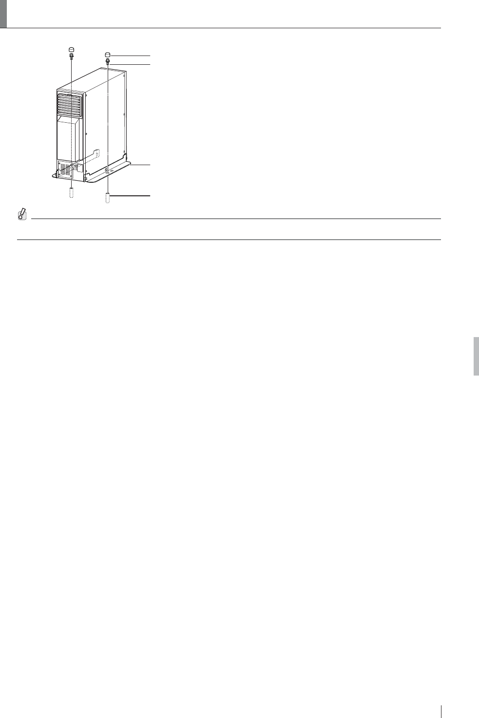
O-5
FDR D-EVO Operation Manual 897N101473E
Appendix O Use of Optional Items
28VLQJWKH5HWDLQLQJ%UDFNHWIRU03
Cap
Bolt
Fixture
Anchor
&RQWDFWD)8-,),/0GHDOHUIRULQVWDOODWLRQRIWKH5HWDLQLQJEUDFNHWIRU03

O-6 FDR D-EVO Operation Manual 897N101473E
Appendix O Use of Optional Items

FDR D-EVO Operation Manual 897N101473E
Maintenance and Inspection
Maintenance and Inspection
0DLQWHQDQFHDQG,QVSHFWLRQ,WHPV$VVLJQHGWR6SHFL¿HG'HDOHU
)RUSHULRGLFDOLQVSHFWLRQRIWKHHTXLSPHQWDQGQHFHVVDU\DUUDQJHPHQWVFRQVXOWRXURI¿FLDOGHDOHU
or local representative.
Periodical Maintenance
0DNHVXUHWKDWWKHSHULRGLFDOPDLQWHQDQFHDQGLQVSHFWLRQDVVLJQHGWRRXURI¿FLDOGHDOHUDUH
SHUIRUPHGDVVSHFL¿HG
0DLQWHQDQFHDQG,QVSHFWLRQ,WHPV$VVLJQHGWR6SHFL¿HG'HDOHU
Periodical Maintenance and Inspection Items Period
Checking of the image Every year
Checking of the operation record by referring to the error log Every year
Checking of the internal units Every 2 years
Main Periodical Replacement Parts
Name of Periodical Replacement Parts Period
Relay (optional) Every 1.5 years
1XPEHURIH[SRVXUHV
* It is recommended that the battery pack (optional) be replaced once a year.
If the duration of use exceeds one year, the capacity of the battery pack will decrease.
The cycles of periodical maintenance and inspection and of parts replacement differ depending on
the usage and the daily operation time.
)RUGHWDLOVFRQWDFWXVGLUHFWO\RURXURI¿FLDOGHDOHU

FDR D-EVO Operation Manual 897N101473E
This device complies with Part 15 of FCC Rules and RSS-Gen of IC Rules. Operation is subject to
the following two conditions:
(1) this device may not cause interference, and (2) this device must accept any interference,
including interference that may cause undesired operation of this device.
FCC WARNING
Changes or modifications not expressly approved by the party responsible for compliance could
void the user’s authority to operate the equipment.
Note : This equipment has been tested and found to comply with the limits for a Class B digital
device, pursuant to part 15 of the FCC Rules. These limits are designed to provide
reasonable protection against harmful interference in a residential installation. This
equipment generates, uses and can radiate radio frequency energy and, if not installed
and used in accordance with the instructions, may cause harmful interference to radio
communications. However,there is no guarantee that interference will not occur in a
particularinstallation.
If this equipment does cause harmful interference to radio or television reception, which can
be determined by turning the equipment off and on, the user is encouraged to try to correct
the interference by one or more of the following measures:
- Reorient or relocate the receiving antenna.
- Increase the separation between the equipment and receiver.
- Connect the equipment into an outlet on a circuit different from that to which the receiver is
connected.
- Consult the dealer or an experienced radio/TV technician for help.
The available scientific evidence does not show that any health problems are associated with using
low power wireless devices.
There is no proof, however, that these low power wireless devices are absolutely safe. Low power
Wireless devices emit low levels of radio frequency energy (RF) in the microwave range while being
used. Whereas high levels of RF can produce health effects (by heating tissue), exposure of low-
level RF that does not produce heating effects causes no known adverse health effects. Many
studies of low-level RF exposures have not found any biological effects.
Some studies have suggested that some biological effects might occur, but such findings have not
been confirmed by additional research. DR-ID600 has been tested and found to comply with FCC/
IC radiation exposure limits set forth for an uncontrolled environment and meets the FCC radio
frequency (RF) Exposure Guidelines in Supplement C to OET65 and RSS-102 of the IC radio
frequency (RF) Exposure rules.
5.15-5.25GHz band is restricted to indoor operations only.
Compliance with FCC requirement 15.407© Date transmission is always initiated by software, which
is the passed down through the MAC, through the digital and analog baseband, and finally to the
RF chip. Several special packets are initiated by the MAC. These are the only ways the digital
baseband portion will turn on the RF transmitter, which it then turns off at the end of the
packet. Therefore, the transmitter will be on only while one of the aforementioned packets is being
transmitted.
In other words, this device automatically discontinue transmission in case of either absence of
information to transmitor operational failure.
(This transmitter must not be co-located or operated in conjunction with any other antenna or
transmitter.)

FUJIFILM MEDICAL SYSTEMS U.S.A., INC.
:(67$9(18(67$0)25'&786$