Fuji Film 01000007 Flat Panel Sensor User Manual 05 Short Term Confidential RIC 24C
Fuji Film Corporation Flat Panel Sensor 05 Short Term Confidential RIC 24C
UserManual.wiki
>
Fuji Film
>
01000007 User Manual
05 (Short-Term Confidential) User Manual_RIC 24C
Navigation menu
Upload a User Manual
Namespaces
Wiki Guide
HTML
PDF
Info
Views
User Manual
Discussion / Help
Navigation
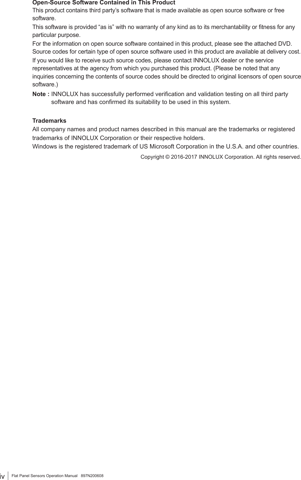
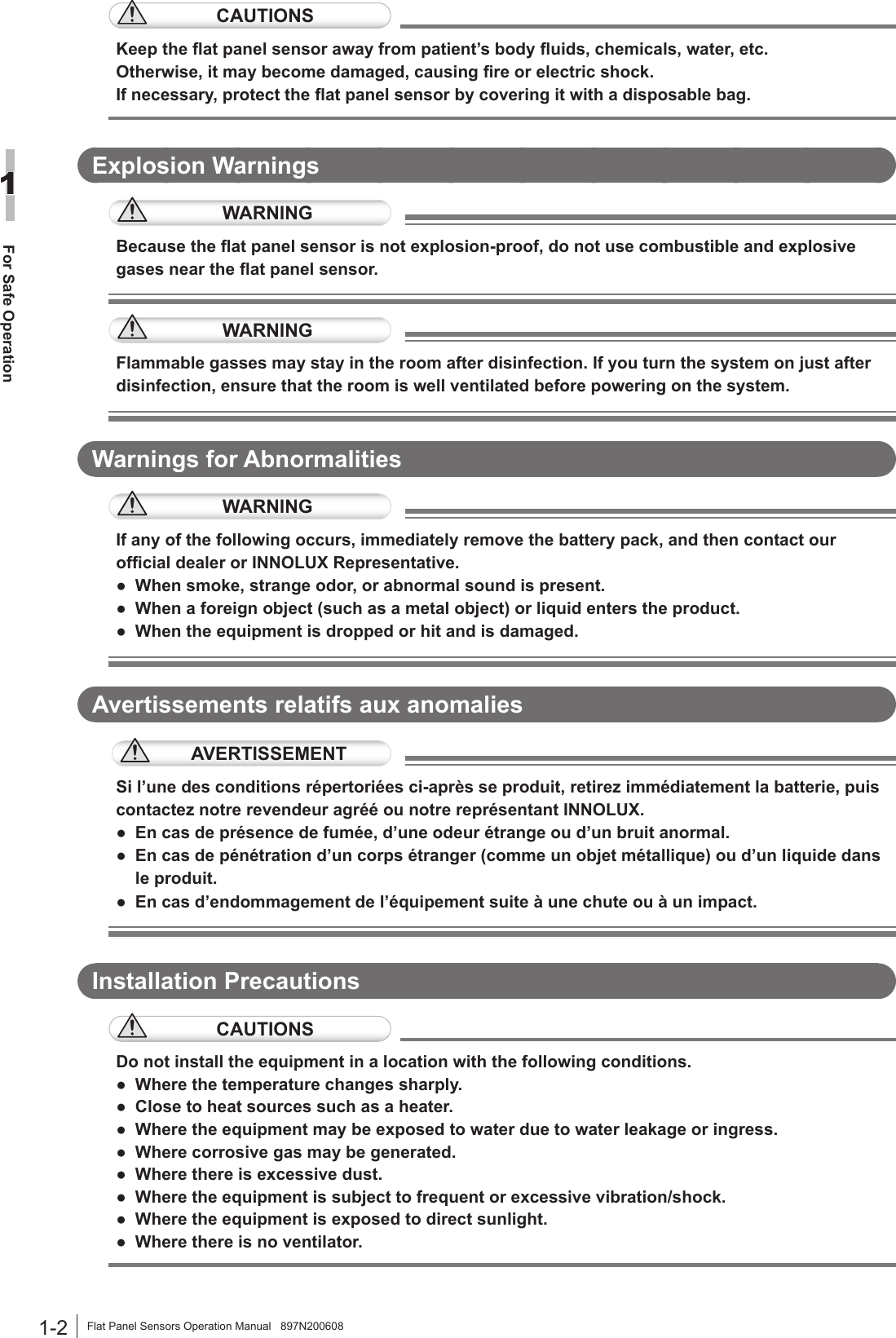
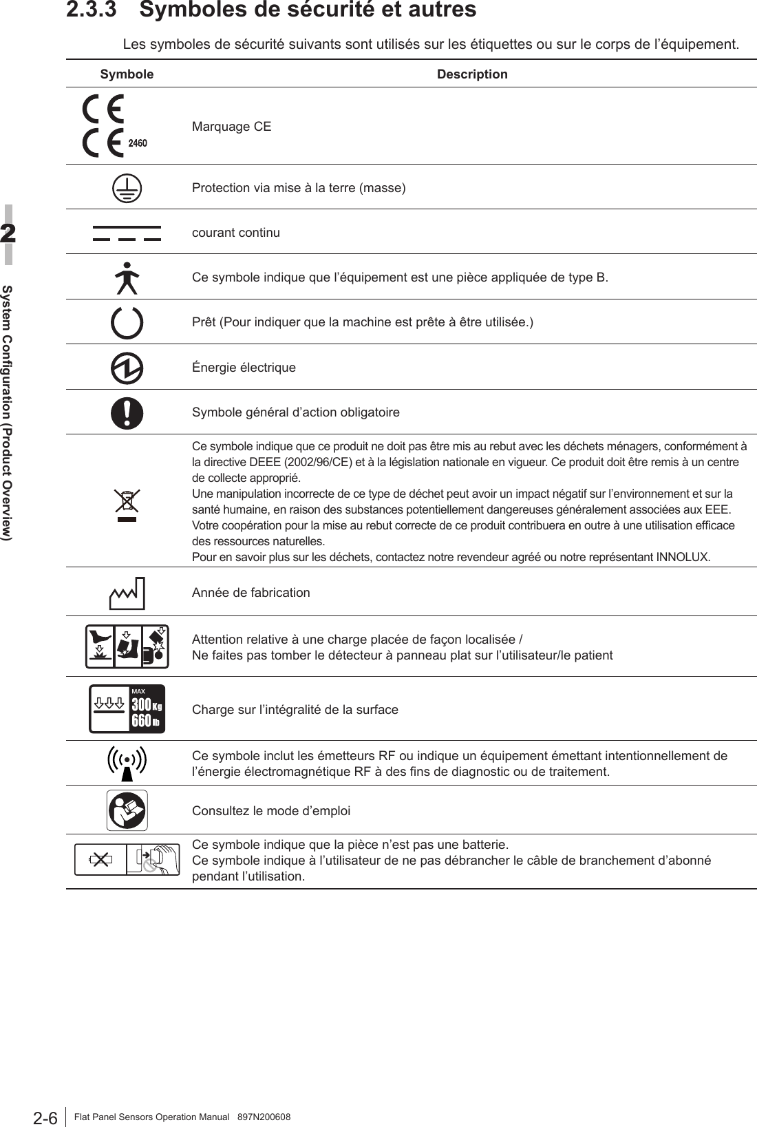
![3-2Basic Operation3Flat Panel Sensors Operation Manual 897N200608 CAUTIONSBefore inserting/removing the at panel sensor into/from the radiographic examination stand, pull out the tray completely. Otherwise, the at panel sensor may be damaged. [1] Upright type CAUTIONS When inserting the at panel sensor into the radiographic examination stand, direct the exposure plane toward the X-ray tube. 1 Pull out the tray. Tray 2 Insert the at panel sensor into the cassette receive with the green mark of the at panel sensor up, and then move it downwards. Cassette receiveGreen mark 3 Set the at panel sensor to the upper part of the tray. 4 Push the tray back into place after setting the at panel sensor. 5 Remove the at panel sensor after use. Pull out the tray, push the cassette receive downwards, and then remove the at panel sensor. Push the tray back into place.](https://usermanual.wiki/Fuji-Film/01000007/User-Guide-3485524-Page-26.png)
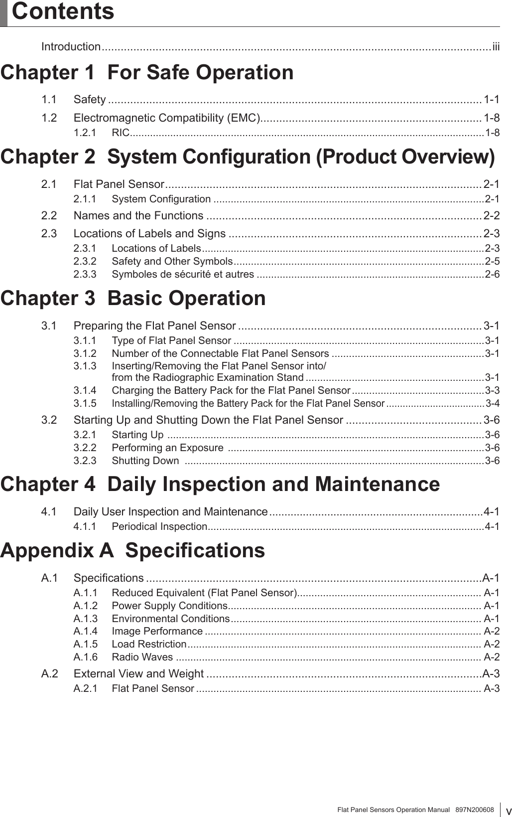
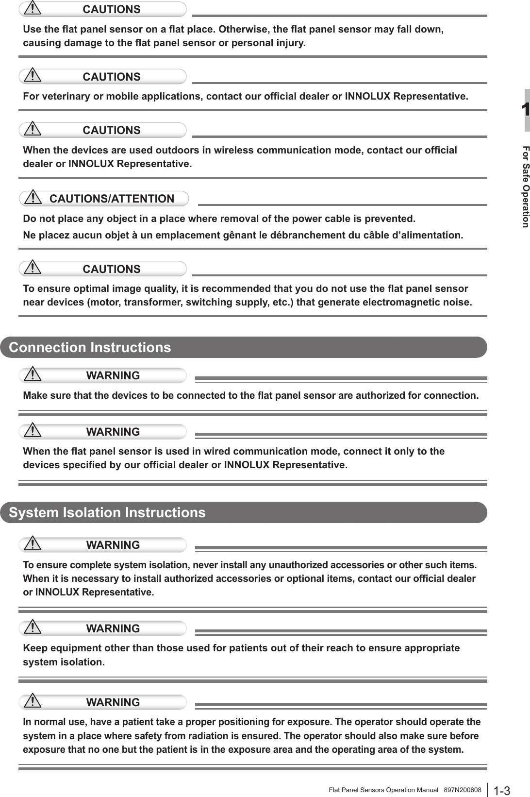
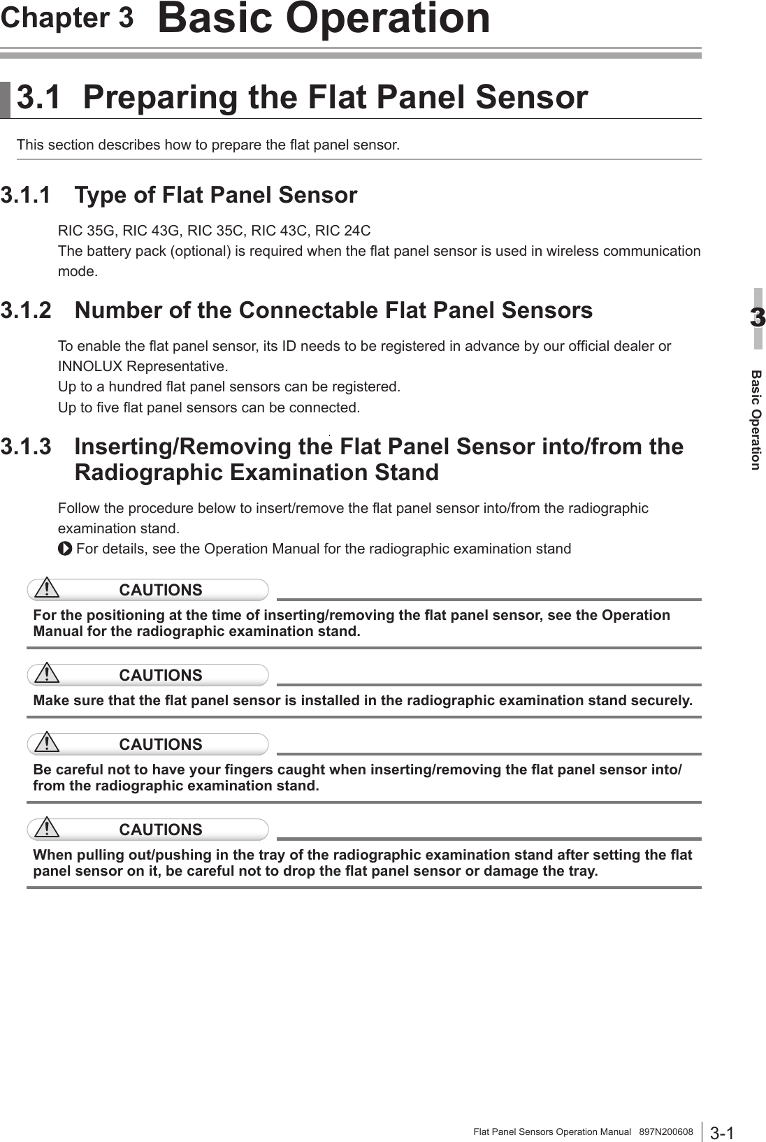
![3-3Basic Operation3Flat Panel Sensors Operation Manual 897N200608[2] Bed typeCAUTIONSWhen inserting the at panel sensor to the radiographic examination stand, direct the exposure plane upwards.1 Pull out the tray by using the handle.Tray2 Pull the cassette stopper, and set the at panel sensor so that its center mark is aligned with the center of the stopper.Cassette stopperCenter mark3 Push the tray back into place by using the handle after setting the at panel sensor.4 Remove the at panel sensor after use.Hold the handle and pull out the tray. Remove the at panel sensor while pulling the cassette stopper, and then push the tray back into place.3.1.4 Charging the Battery Pack for the Flat Panel SensorUse the battery charger recommended by INNOLUX Corporation.For details on operations, refer to the instruction manual for the battery charger.](https://usermanual.wiki/Fuji-Film/01000007/User-Guide-3485524-Page-27.png)
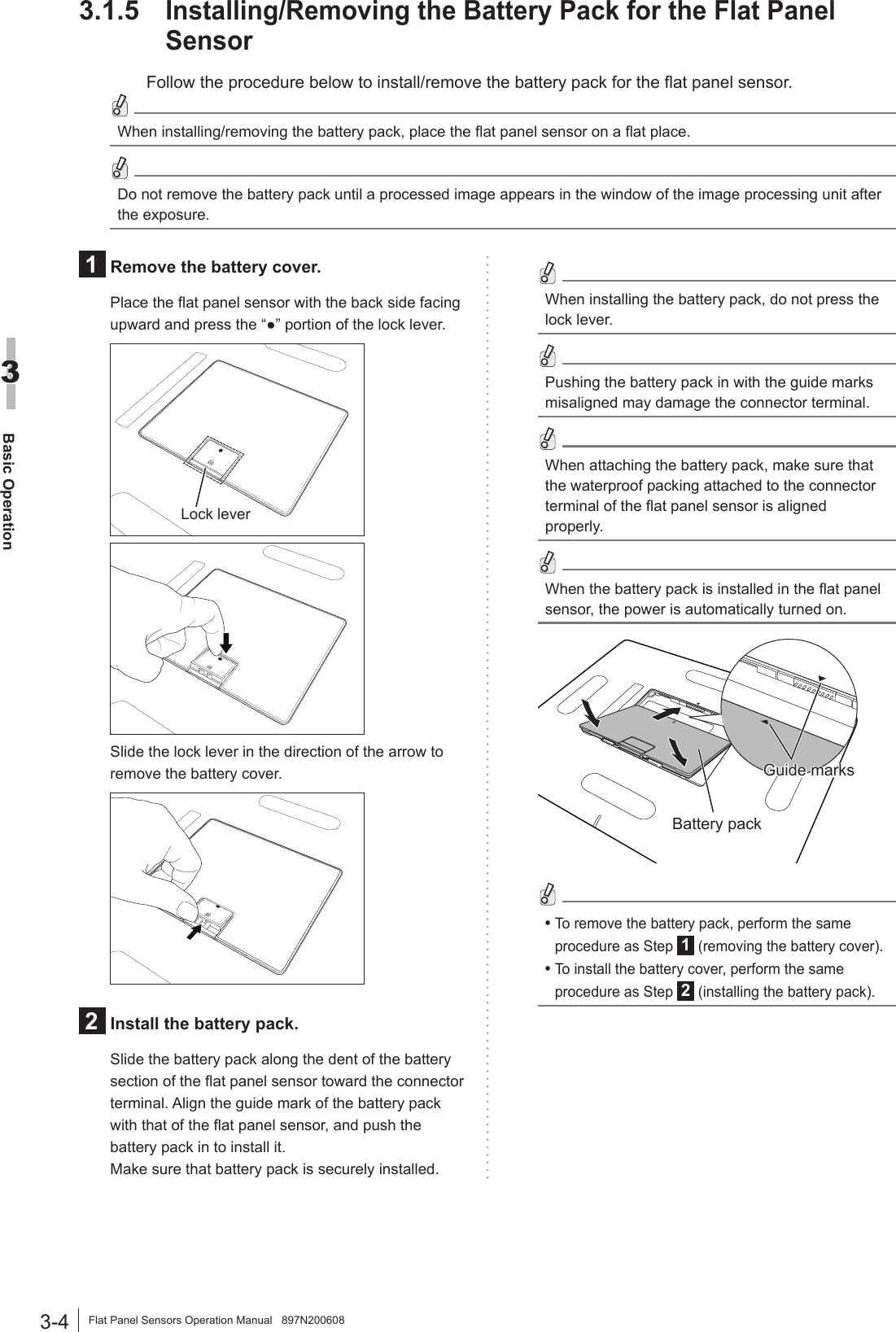

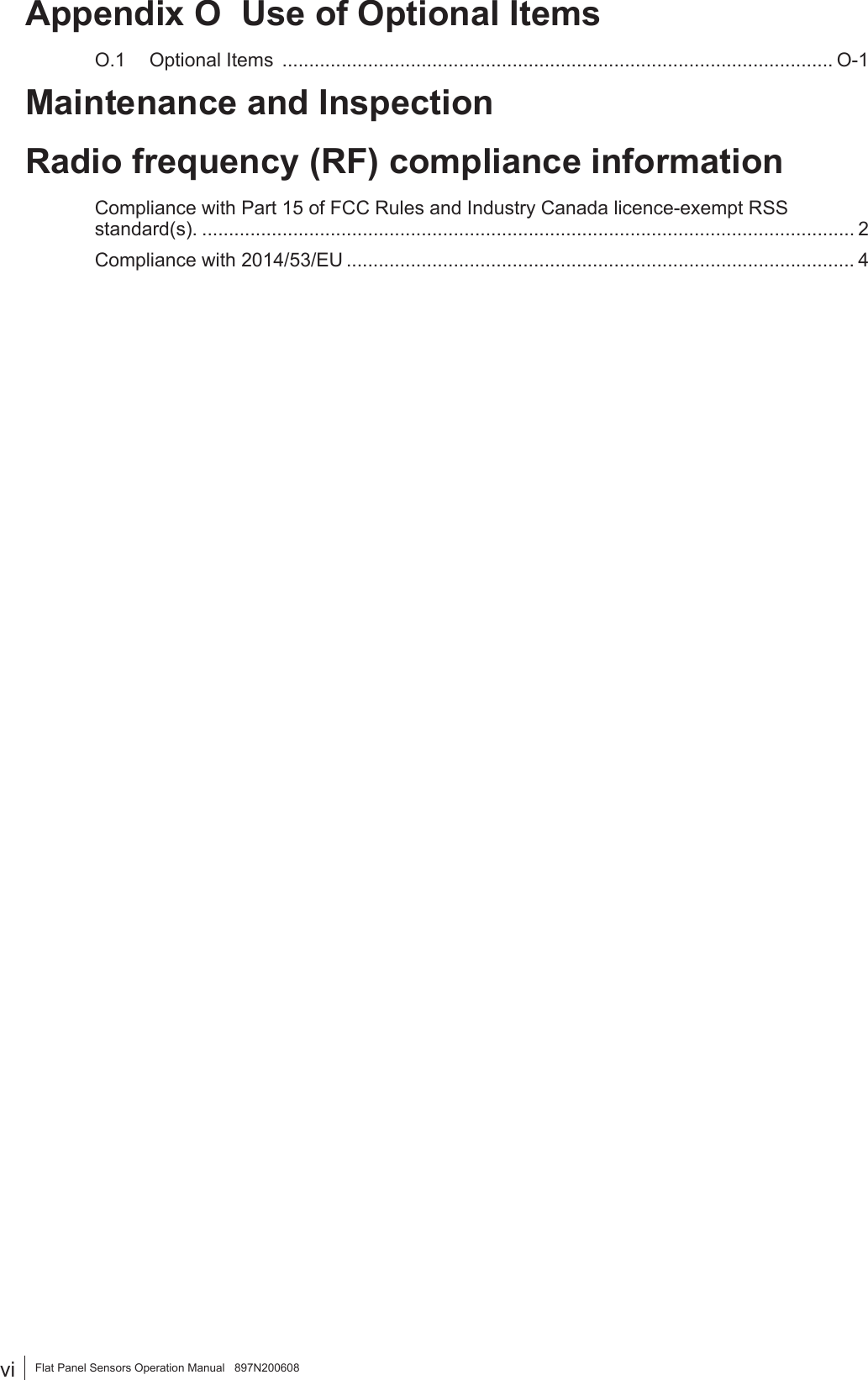
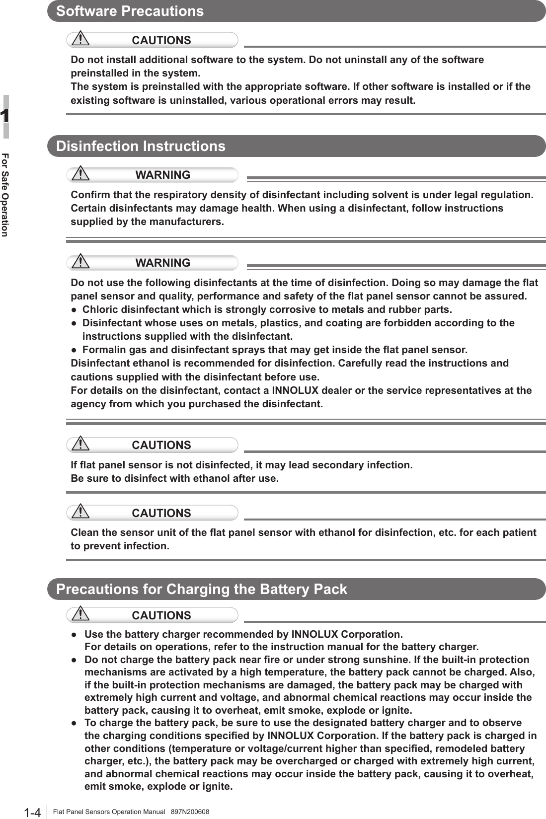
![Maintenance and InspectionFlat Panel Sensors Operation Manual 897N200608 Maintenance and Inspection1 Maintenance and Inspection Items Assigned to Specied DealerFor periodical inspection of the equipment and necessary arrangements, consult our ofcial dealer or local representative. Periodical MaintenanceMake sure that the periodical maintenance and inspection assigned to our ofcial dealer or INNOLUX Representative are performed as specied.Maintenance and Inspection Items Assigned to Specied DealerPeriodical Maintenance and Inspection Items PeriodChecking of the image Every yearChecking of the operation record by referring to the error log Every yearChecking of the at panel sensor Every 2 years* It is recommended that the battery pack be replaced, if the battery storage capacity becomes lower than 60%. The battery pack should be replaced when the operable time is less than the following. ● RIC 35G/RIC 43G/RIC 35C/RIC 43C/RIC 24C : 100 minutes (1 hour and 40 minutes) * Refer to the operable time displayed on the image processing unit when the battery pack is fully charged and no exposure menu is registered. * Depending on the usage environment, etc., the displayed time is slightly different from the actual operable time. (Reference) Time for battery pack replacement Battery storage capacity [%]Operable time [Minute]120100806060402000 30 60 90 120 150 210 240180Time for replacement:Less than 100 minutes(1 hour and 40 minutes)The cycles of periodical maintenance and inspection and of parts replacement differ depending on the usage and the daily operation time.For details, contact our ofcial dealer or INNOLUX Representative.](https://usermanual.wiki/Fuji-Film/01000007/User-Guide-3485524-Page-39.png)
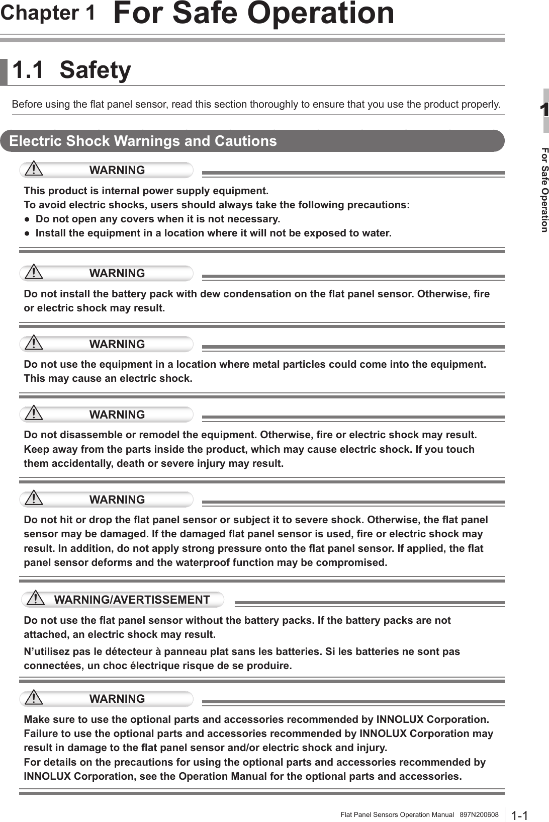
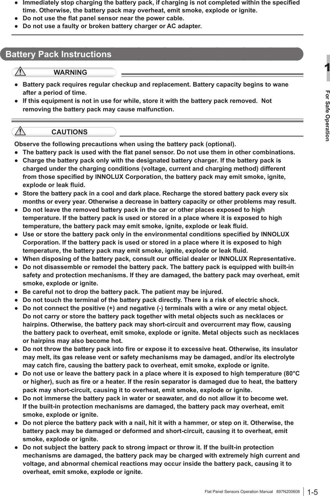
![Maintenance and InspectionFlat Panel Sensors Operation Manual 897N200608Compliance with 2014/53/EUManufacture’s Name: INNOLUX CorporationManufacture’s Address: No.3, Sec. 1, Huansi Rd., Tainan City, Southern Taiwan Science Park, 74147, Taiwan (R.O.C.)declares that the product:Model Number: RIC 35G, RIC 43G, RIC 35C, RIC 43C, RIC 24CThe product complies with the requirements of the RE Directive 2014/53/EU.The shipment schedule country is as follows.AT BE BG CH CYCZ DE DK EE ESFI FR GB GR HRHU IE IS IT LILT LU LV MK MTNL NO PL PT ROSE SI SK TR[BG]BulgarianС настоящето, INNOLUX, декларира, че RIC 35G, RIC 43G, RIC 35C, RIC 43C, RIC 24C е в съответствие със съществените изисквания и другитеприложими разпоредби на Директива 2014/53/EC.[CS]CzechINNOLUX tímto prohlašuje, že RIC 35G, RIC 43G, RIC 35C, RIC 43C, RIC 24C splňuje základní požadavky a všechna příslušná ustanoveni Směrnice 2014/53/EU.[DA]DanishUndertegnede INNOLUX erklærer herved, at følgende udstyr RIC 35G, RIC 43G, RIC 35C, RIC 43C, RIC 24C overholder de væsentlige krav og øvrige relevante krav i direktiv 2014/53/EU.[DE] GermanHiermit erklärt INNOLUX, dass sich das Gerät RIC 35G, RIC 43G, RIC 35C, RIC 43C, RIC 24C in Übereinstimmung mit den grundlegenden Anforderungen und den übrigen einschlägigen Bestimmungen der Richtlinie 2014/53/EU bendet.[EN]EnglishHereby, INNOLUX, declares that this RIC 35G, RIC 43G, RIC 35C, RIC 43C, RIC 24C is in compliance with the essential requirements and other relevant provisions of Directive 2014/53/EU.[ES]SpanishPor la presente, INNOLUX, declara que este RIC 35G, RIC 43G, RIC 35C, RIC 43C, RIC 24C cumple con los requisitos esenciales y otras exigencias relevantes de la Directiva 2014/53/UE.[ET] EstonianKäesolevaga kinnitab INNOLUX seadme RIC 35G, RIC 43G, RIC 35C, RIC 43C, RIC 24C vastavust direktiivi 2014/53/EL põhinõuetele ja nimetatud direktiivist tulenevatele teistele asjakohastele sätetele.[FI]FinishINNOLUX vakuuttaa täten että RIC 35G, RIC 43G, RIC 35C, RIC 43C, RIC 24C tyyppinen laite on direktiivin 2014/53/EU oleellisten vaatimusten ja sitä koskevien direktiivin muiden ehtojen mukainen.](https://usermanual.wiki/Fuji-Film/01000007/User-Guide-3485524-Page-42.png)
![Maintenance and InspectionFlat Panel Sensors Operation Manual 897N200608[FR]FrenchPar la présente, INNOLUX déclare que l’appareil RIC 35G, RIC 43G, RIC 35C, RIC 43C, RIC 24C est conforme aux exigences essentielles et aux autres dispositions pertinentes de la directive 2014/53/UE.[EL]GreekΜΕ ΤΗΝ ΠΑΡΟΥΣΑ Ο ΚΑΤΑΣΚΕΥΑΣΤΗΣ INNOLUX ΔΗΛΩΝΕΙ ΟΤΙ RIC 35G, RIC 43G, RIC 35C, RIC 43C, RIC 24C ΣΥΜΜΟΡΦΩΝΕΤΑΙ ΠΡΟΣ ΤΙΣ ΟΥΣΙΩΔΕΙΣ ΑΠΑΙΤΗΣΕΙΣ ΚΑΙ ΤΙΣ ΛΟΙΠΕΣ ΣΧΕΤΙΚΕΣ ΔΙΑΤΑΞΕΙΣ ΤΗΣ ΟΔΗΓΙΑΣ 2014/53/EE[HU]HungarianA INNOLUX ezzennel kijelenti, hogy a RIC 35G, RIC 43G, RIC 35C, RIC 43C, RIC 24C típusú beren-dezés teljesíti az alapvető követelményeket és más 2014/53/EU irányelvben meghatározott vonatkozó rendelkezéseket.[HR]CroatianOvime, INNOLUX, potvrđuje da je RIC 35G, RIC 43G, RIC 35C, RIC 43C, RIC 24C u sukladnost sa osnovnim zahtjevima i drugim važnim odredbama Direktive 2014/53/EU.[IS] IcelandicHér með lýsir INNOLUX yr því að RIC 35G, RIC 43G, RIC 35C, RIC 43C, RIC 24C er í samræmi við grunnkröfur og aðrar kröfur, sem gerðar eru í tilskipun 2014/53/EU[IT]ItalianCon la presente INNOLUX dichiara che questo RIC 35G, RIC 43G, RIC 35C, RIC 43C, RIC 24C è conforme ai requisiti essenziali ed alle altre disposizioni pertinenti stabilite dalla direttiva 2014/53/UE.[LV]LatvianAr šo INNOLUX deklarē, ka RIC 35G, RIC 43G, RIC 35C, RIC 43C, RIC 24C atbilst Direktīvas 2014/53/ES būtiskajām prasībām un citiem ar to saistītajiem noteikumiem.[LT]LithuanianŠiuo INNOLUX deklaruoja, kad šis RIC 35G, RIC 43G, RIC 35C, RIC 43C, RIC 24C atitinka esminius reikalavimus ir kitas 2014/53/ES Direktyvos nuostatas[МК]MacedonianINNOLUX, изјавува дека овој RIC 35G, RIC 43G, RIC 35C, RIC 43C, RIC 24C е во согласност со суштинските барања и други релевантни одредби на Директивата 2014/53/EU.[MT]MalteseHawnhekk, INNOLUX, jiddikjara li dan RIC 35G, RIC 43G, RIC 35C, RIC 43C, RIC 24C jikkonforma mal-ħtiġijiet essenzjali u ma provvedimenti oħrajn relevanti li hemm d-Dirrettiva 2014/53/UE.[NL]DutchHierbij verklaart INNOLUX dat het toestel l RIC 35G, RIC 43G, RIC 35C, RIC 43C, RIC 24C in overeenstemming is met de essentiële eisen en de andere relevante bepalin-gen van richtlijn 2014/53/EU.[NO]NorwegianINNOLUX erklærer herved at utstyret RIC 35G, RIC 43G, RIC 35C, RIC 43C, RIC 24C er i samsvar med de grunnleggende krav og øvrige relevante krav i direktiv 2014/53/EU.[PL]PolishNiniejszym INNOLUX deklaruje że RIC 35G, RIC 43G, RIC 35C, RIC 43C, RIC 24C jest zgodny z zasadniczymi wymaganiami i innymi właściwymi postanowieniami Dyrektywy 2014/53/UE.[PT]PortugueseEu, INNOLUX, declaro que o RIC 35G, RIC 43G, RIC 35C, RIC 43C, RIC 24C cumpre os requisitos essenciais e outras provisões relevantes da Directiva 2014/53/UE.[RO]RomanianPrin prezenta, INNOLUX, declară că aparatul RIC 35G, RIC 43G, RIC 35C, RIC 43C, RIC 24C este în conformitate cu cerinţele esenţiale şi cu alte prevederi pertinente ale Directivei 2014/53/UE.[SK]SlovakINNOLUX týmto vyhlasuje, že RIC 35G, RIC 43G, RIC 35C, RIC 43C, RIC 24C spĺňa základné požiadavky a všetky príslušné ustanovenia Smernice 2014/53/EÚ.](https://usermanual.wiki/Fuji-Film/01000007/User-Guide-3485524-Page-43.png)
![Maintenance and InspectionFlat Panel Sensors Operation Manual 897N200608[SL]SlovenianINNOLUX izjavlja, da je ta RIC 35G, RIC 43G, RIC 35C, RIC 43C, RIC 24C v skladu z bistvenimi zahtevami in drugimi relevantnimi določili direktive 2014/53/EU.[SV]SwedishHärmed intygar INNOLUX, att denna RIC 35G, RIC 43G, RIC 35C, RIC 43C, RIC 24C är förenligt med de grundläggande kraven och andra relevanta bestämmelser i direktivet 2014/53/EU.[TR]Turkishİşbu belge ile INNOLUX, bu RIC 35G, RIC 43G, RIC 35C, RIC 43C, RIC 24C ürününün 2014/53/AB sayılı Yönerge’nin temel şartlarıyla ve diğer ilgili hükümleriyle uyumlu olduğunu beyan eder.](https://usermanual.wiki/Fuji-Film/01000007/User-Guide-3485524-Page-44.png)
![Maintenance and InspectionFlat Panel Sensors Operation Manual 897N200608Innolux EC Declaration of ConformityManufacturer : Address : Innolux Corporation Product : RIC 35G, RIC 35C, RIC 43G, RIC 43C, RIC 24C Model No. : RIC 35G, RIC 35C, RIC 43G, RIC 43C, RIC 24C Applicable Product Units : Serial No. ***0001 or later Control Software: 0X0221 or later We, Innolux Corporation, herewith declare under our sole responsibility that the product(s) identified in this declaration conforms to the provisions of the following Directive and Standards. Directive : RE Directive: 2014/53/EU Standards : SAR EN 62311:2008 Radio EN 300 328 V1.9.1 EN 301 893 V1.8.1 EMC EN 301 489-1 V1.9.2 EN 301 489-17 V2.2.1 Safety EN 60601-1:2006/A1:2013 Place and Date of issue [Area], Tiwan [date] Signature : Name : Function : Innolux Corporation](https://usermanual.wiki/Fuji-Film/01000007/User-Guide-3485524-Page-45.png)