Fuji Film 01000007 Flat Panel Sensor User Manual 05 Short Term Confidential RIC 24C
Fuji Film Corporation Flat Panel Sensor 05 Short Term Confidential RIC 24C
05 (Short-Term Confidential) User Manual_RIC 24C

Flat Panel Sensors
RIC 35G
RIC 43G
RIC 35C
RIC 43C
RIC 24C
Operation Manual
1st Edition : March 2017
For Safe Operation
System
Conguration
(Product Overview)
Basic Operation
Daily Inspection and
Maintenance
Appendix
Maintenance and
Inspection
This Operation Manual describes details on how to operate the at panel sensor
and cautions to be observed when operating it.
After reading this manual, store it nearby the at panel sensor so that you can see
it whenever necessary.

ii Flat Panel Sensors Operation Manual 897N200608

iii
Flat Panel Sensors Operation Manual 897N200608
Introduction
The indirect-conversion at panel sensor is a device which acquires a general radiograph.
The at panel sensor is a component of RIC.
Available at panel sensor is RIC 35G/RIC 43G/RIC 35C/RIC 43C/RIC 24C.
RIC 35G, RIC 43G, RIC 35C, RIC 43C and
RIC 24C
:
Wireless communication mode or wired communication mode is available. When used in wireless
communication mode, an access point and battery pack (optional) are required.
Each at panel sensor complies with IEC 62220-1 (MEDICAL ELECTRICAL EQUIPMENT -
CHARACTERISTICS OF DIGITAL X-RAY IMAGING DEVICES - ) as a general X-ray radiography
equipment.
The detector of at panel sensors features 150 micron pixel pitch, a wide 16-bit dynamic range and
exposure times up to 3.8 seconds.
This Operation Manual includes descriptions of matters necessary when using the at panel sensor
such as the equipment overview, operation procedures and precautions to observe, as well as daily
inspections and maintenance.
Accompanying documents were originally drafted in the English language.
Installation may only be conducted by authorized service personnel.
CAUTIONS
1. No part or all of this manual may be reproduced in any form without prior permission.
2. The information contained in this manual may be subject to change without prior notice.
3. INNOLUX Corporation shall not be liable for malfunctions and damages resulting from
installation, relocation, remodeling, maintenance, and repair performed by other than dealers
specied by INNOLUX Corporation.
4. INNOLUX Corporation shall not be liable for malfunctions and damages of INNOLUX
Corporation products due to products of other manufacturers not supplied by INNOLUX
Corporation.
5. INNOLUX Corporation shall not be liable for malfunctions and damages resulting from
remodeling, maintenance, and repair using repair parts other than those specied by
INNOLUX Corporation.
6. INNOLUX Corporation shall not be liable for malfunctions and damages resulting from
negligence of precautions and operating methods contained in this manual.
7. INNOLUX Corporation shall not be liable for malfunctions and damages resulting from use
under environment conditions outside the range of using conditions for this product such as
power supply, installation environment, etc. contained in this manual.
8. INNOLUX Corporation shall not be liable for malfunctions and damages resulting from
natural disasters such as res, earthquakes, oods, lightning, etc.
This system is classied as a medical device under EC Directive 93/42/EEC.
Process waste correctly, as stipulated by local law or any regulations that apply.
Caution : Rx Only in the United States (Federal law restricts this device to sale by or on the order
of a physician.)

iv Flat Panel Sensors Operation Manual 897N200608
Open-Source Software Contained in This Product
This product contains third party’s software that is made available as open source software or free
software.
This software is provided “as is” with no warranty of any kind as to its merchantability or tness for any
particular purpose.
For the information on open source software contained in this product, please see the attached DVD.
Source codes for certain type of open source software used in this product are available at delivery cost.
If you would like to receive such source codes, please contact INNOLUX dealer or the service
representatives at the agency from which you purchased this product. (Please be noted that any
inquiries concerning the contents of source codes should be directed to original licensors of open source
software.)
Note : INNOLUX has successfully performed verication and validation testing on all third party
software and has conrmed its suitability to be used in this system.
Trademarks
All company names and product names described in this manual are the trademarks or registered
trademarks of INNOLUX Corporation or their respective holders.
Windows is the registered trademark of US Microsoft Corporation in the U.S.A. and other countries.
Copyright © 2016-2017 INNOLUX Corporation. All rights reserved.

v
Flat Panel Sensors Operation Manual 897N200608
Contents
Introduction ........................................................................................................................... iii
Chapter 1 For Safe Operation
1.1 Safety ......................................................................................................................1-1
1.2 Electromagnetic Compatibility (EMC) ......................................................................1-8
1.2.1 RIC ...........................................................................................................................1-8
Chapter 2
System Conguration (Product Overview)
2.1 Flat Panel Sensor ....................................................................................................2-1
2.1.1 System Conguration ..............................................................................................2-1
2.2 Names and the Functions .......................................................................................2-2
2.3 Locations of Labels and Signs ................................................................................2-3
2.3.1 Locations of Labels .................................................................................................. 2-3
2.3.2 Safety and Other Symbols ....................................................................................... 2-5
2.3.3 Symboles de sécurité et autres ...............................................................................2-6
Chapter 3 Basic Operation
3.1 Preparing the Flat Panel Sensor .............................................................................3-1
3.1.1 Type of Flat Panel Sensor .......................................................................................3-1
3.1.2 Number of the Connectable Flat Panel Sensors .....................................................3-1
3.1.3 Inserting/Removing the Flat Panel Sensor into/
from the Radiographic Examination Stand ..............................................................3-1
3.1.4 Charging the Battery Pack for the Flat Panel Sensor ..............................................3-3
3.1.5
Installing/Removing the Battery Pack for the Flat Panel Sensor ....................................3-4
3.2 Starting Up and Shutting Down the Flat Panel Sensor ...........................................3-6
3.2.1 Starting Up .............................................................................................................. 3-6
3.2.2 Performing an Exposure .........................................................................................3-6
3.2.3 Shutting Down ........................................................................................................3-6
Chapter 4 Daily Inspection and Maintenance
4.1 Daily User Inspection and Maintenance ......................................................................4-1
4.1.1 Periodical Inspection ................................................................................................4-1
Appendix A Specications
A.1 Specications ..........................................................................................................A-1
A.1.1 Reduced Equivalent (Flat Panel Sensor) ................................................................ A-1
A.1.2 Power Supply Conditions ........................................................................................ A-1
A.1.3 Environmental Conditions ....................................................................................... A-1
A.1.4 Image Performance ................................................................................................ A-2
A.1.5 Load Restriction ...................................................................................................... A-2
A.1.6 Radio Waves .......................................................................................................... A-2
A.2 External View and Weight .......................................................................................A-3
A.2.1 Flat Panel Sensor ................................................................................................... A-3

vi Flat Panel Sensors Operation Manual 897N200608
Appendix O Use of Optional Items
O.1 Optional Items ....................................................................................................... O-1
Maintenance and Inspection
Radio frequency (RF) compliance information
Compliance with Part 15 of FCC Rules and Industry Canada licence-exempt RSS
standard(s). .......................................................................................................................... 2
Compliance with 2014/53/EU ............................................................................................... 4
1-1
For Safe Operation
1
Flat Panel Sensors Operation Manual 897N200608
Chapter 1 For Safe Operation
1.1 Safety
Before using the at panel sensor, read this section thoroughly to ensure that you use the product properly.
Electric Shock Warnings and Cautions
WARNING
This product is internal power supply equipment.
To avoid electric shocks, users should always take the following precautions:
● Do not open any covers when it is not necessary.
● Install the equipment in a location where it will not be exposed to water.
WARNING
Do not install the battery pack with dew condensation on the at panel sensor. Otherwise, re
or electric shock may result.
WARNING
Do not use the equipment in a location where metal particles could come into the equipment.
This may cause an electric shock.
WARNING
Do not disassemble or remodel the equipment. Otherwise, re or electric shock may result.
Keep away from the parts inside the product, which may cause electric shock. If you touch
them accidentally, death or severe injury may result.
WARNING
Do not hit or drop the at panel sensor or subject it to severe shock. Otherwise, the at panel
sensor may be damaged. If the damaged at panel sensor is used, re or electric shock may
result. In addition, do not apply strong pressure onto the at panel sensor. If applied, the at
panel sensor deforms and the waterproof function may be compromised.
WARNING/AVERTISSEMENT
Do not use the at panel sensor without the battery packs. If the battery packs are not
attached, an electric shock may result.
N’utilisez pas le détecteur à panneau plat sans les batteries. Si les batteries ne sont pas
connectées, un choc électrique risque de se produire.
WARNING
Make sure to use the optional parts and accessories recommended by INNOLUX Corporation.
Failure to use the optional parts and accessories recommended by INNOLUX Corporation may
result in damage to the at panel sensor and/or electric shock and injury.
For details on the precautions for using the optional parts and accessories recommended by
INNOLUX Corporation, see the Operation Manual for the optional parts and accessories.
1-2
For Safe Operation
1
Flat Panel Sensors Operation Manual 897N200608
CAUTIONS
Keep the at panel sensor away from patient’s body uids, chemicals, water, etc.
Otherwise, it may become damaged, causing re or electric shock.
If necessary, protect the at panel sensor by covering it with a disposable bag.
Explosion Warnings
WARNING
Because the at panel sensor is not explosion-proof, do not use combustible and explosive
gases near the at panel sensor.
WARNING
Flammable gasses may stay in the room after disinfection. If you turn the system on just after
disinfection, ensure that the room is well ventilated before powering on the system.
Warnings for Abnormalities
WARNING
If any of the following occurs, immediately remove the battery pack, and then contact our
ofcial dealer or INNOLUX Representative.
● When smoke, strange odor, or abnormal sound is present.
● When a foreign object (such as a metal object) or liquid enters the product.
● When the equipment is dropped or hit and is damaged.
Avertissements relatifs aux anomalies
AVERTISSEMENT
Si l’une des conditions répertoriées ci-après se produit, retirez immédiatement la batterie, puis
contactez notre revendeur agréé ou notre représentant INNOLUX.
● En cas de présence de fumée, d’une odeur étrange ou d’un bruit anormal.
● En cas de pénétration d’un corps étranger (comme un objet métallique) ou d’un liquide dans
le produit.
● En cas d’endommagement de l’équipement suite à une chute ou à un impact.
Installation Precautions
CAUTIONS
Do not install the equipment in a location with the following conditions.
● Where the temperature changes sharply.
● Close to heat sources such as a heater.
● Where the equipment may be exposed to water due to water leakage or ingress.
● Where corrosive gas may be generated.
● Where there is excessive dust.
● Where the equipment is subject to frequent or excessive vibration/shock.
● Where the equipment is exposed to direct sunlight.
● Where there is no ventilator.
1-3
For Safe Operation
1
Flat Panel Sensors Operation Manual 897N200608
CAUTIONS
Use the at panel sensor on a at place. Otherwise, the at panel sensor may fall down,
causing damage to the at panel sensor or personal injury.
CAUTIONS
For veterinary or mobile applications, contact our ofcial dealer or INNOLUX Representative.
CAUTIONS
When the devices are used outdoors in wireless communication mode, contact our ofcial
dealer or INNOLUX Representative.
CAUTIONS/ATTENTION
Do not place any object in a place where removal of the power cable is prevented.
Ne placez aucun objet à un emplacement gênant le débranchement du câble d’alimentation.
CAUTIONS
To ensure optimal image quality, it is recommended that you do not use the at panel sensor
near devices (motor, transformer, switching supply, etc.) that generate electromagnetic noise.
Connection Instructions
WARNING
Make sure that the devices to be connected to the at panel sensor are authorized for connection.
WARNING
When the at panel sensor is used in wired communication mode, connect it only to the
devices specied by our ofcial dealer or INNOLUX Representative.
System Isolation Instructions
WARNING
To ensure complete system isolation, never install any unauthorized accessories or other such items.
When it is necessary to install authorized accessories or optional items, contact our ofcial dealer
or INNOLUX Representative.
WARNING
Keep equipment other than those used for patients out of their reach to ensure appropriate
system isolation.
WARNING
In normal use, have a patient take a proper positioning for exposure. The operator should operate the
system in a place where safety from radiation is ensured. The operator should also make sure before
exposure that no one but the patient is in the exposure area and the operating area of the system.
1-4
For Safe Operation
1
Flat Panel Sensors Operation Manual 897N200608
Software Precautions
CAUTIONS
Do not install additional software to the system. Do not uninstall any of the software
preinstalled in the system.
The system is preinstalled with the appropriate software. If other software is installed or if the
existing software is uninstalled, various operational errors may result.
Disinfection Instructions
WARNING
Conrm that the respiratory density of disinfectant including solvent is under legal regulation.
Certain disinfectants may damage health. When using a disinfectant, follow instructions
supplied by the manufacturers.
WARNING
Do not use the following disinfectants at the time of disinfection. Doing so may damage the at
panel sensor and quality, performance and safety of the at panel sensor cannot be assured.
● Chloric disinfectant which is strongly corrosive to metals and rubber parts.
● Disinfectant whose uses on metals, plastics, and coating are forbidden according to the
instructions supplied with the disinfectant.
● Formalin gas and disinfectant sprays that may get inside the at panel sensor.
Disinfectant ethanol is recommended for disinfection. Carefully read the instructions and
cautions supplied with the disinfectant before use.
For details on the disinfectant, contact a INNOLUX dealer or the service representatives at the
agency from which you purchased the disinfectant.
CAUTIONS
If at panel sensor is not disinfected, it may lead secondary infection.
Be sure to disinfect with ethanol after use.
CAUTIONS
Clean the sensor unit of the at panel sensor with ethanol for disinfection, etc. for each patient
to prevent infection.
Precautions for Charging the Battery Pack
CAUTIONS
● Use the battery charger recommended by INNOLUX Corporation.
For details on operations, refer to the instruction manual for the battery charger.
● Do not charge the battery pack near re or under strong sunshine. If the built-in protection
mechanisms are activated by a high temperature, the battery pack cannot be charged. Also,
if the built-in protection mechanisms are damaged, the battery pack may be charged with
extremely high current and voltage, and abnormal chemical reactions may occur inside the
battery pack, causing it to overheat, emit smoke, explode or ignite.
● To charge the battery pack, be sure to use the designated battery charger and to observe
the charging conditions specied by INNOLUX Corporation. If the battery pack is charged in
other conditions (temperature or voltage/current higher than specied, remodeled battery
charger, etc.), the battery pack may be overcharged or charged with extremely high current,
and abnormal chemical reactions may occur inside the battery pack, causing it to overheat,
emit smoke, explode or ignite.

1-5
For Safe Operation
1
Flat Panel Sensors Operation Manual 897N200608
● Immediately stop charging the battery pack, if charging is not completed within the specied
time. Otherwise, the battery pack may overheat, emit smoke, explode or ignite.
● Do not use the at panel sensor near the power cable.
● Do not use a faulty or broken battery charger or AC adapter.
Battery Pack Instructions
WARNING
● Battery pack requires regular checkup and replacement. Battery capacity begins to wane
after a period of time.
● If this equipment is not in use for while, store it with the battery pack removed. Not
removing the battery pack may cause malfunction.
CAUTIONS
Observe the following precautions when using the battery pack (optional).
● The battery pack is used with the at panel sensor. Do not use them in other combinations.
● Charge the battery pack only with the designated battery charger. If the battery pack is
charged under the charging conditions (voltage, current and charging method) different
from those specied by INNOLUX Corporation, the battery pack may emit smoke, ignite,
explode or leak uid.
● Store the battery pack in a cool and dark place. Recharge the stored battery pack every six
months or every year. Otherwise a decrease in battery capacity or other problems may result.
● Do not leave the removed battery pack in the car or other places exposed to high
temperature. If the battery pack is used or stored in a place where it is exposed to high
temperature, the battery pack may emit smoke, ignite, explode or leak uid.
● Use or store the battery pack only in the environmental conditions specied by INNOLUX
Corporation. If the battery pack is used or stored in a place where it is exposed to high
temperature, the battery pack may emit smoke, ignite, explode or leak uid.
● When disposing of the battery pack, consult our ofcial dealer or INNOLUX Representative.
● Do not disassemble or remodel the battery pack. The battery pack is equipped with built-in
safety and protection mechanisms. If they are damaged, the battery pack may overheat, emit
smoke, explode or ignite.
● Be careful not to drop the battery pack. The patient may be injured.
● Do not touch the terminal of the battery pack directly. There is a risk of electric shock.
● Do not connect the positive (+) and negative (-) terminals with a wire or any metal object.
Do not carry or store the battery pack together with metal objects such as necklaces or
hairpins. Otherwise, the battery pack may short-circuit and overcurrent may ow, causing
the battery pack to overheat, emit smoke, explode or ignite. Metal objects such as necklaces
or hairpins may also become hot.
●
Do not throw the battery pack into re or expose it to excessive heat. Otherwise, its insulator
may melt, its gas release vent or safety mechanisms may be damaged, and/or its electrolyte
may catch re, causing the battery pack to overheat, emit smoke, explode or ignite.
● Do not use or leave the battery pack in a place where it is exposed to high temperature (80°C
or higher), such as re or a heater. If the resin separator is damaged due to heat, the battery
pack may short-circuit, causing it to overheat, emit smoke, explode or ignite.
● Do not immerse the battery pack in water or seawater, and do not allow it to become wet.
If the built-in protection mechanisms are damaged, the battery pack may overheat, emit
smoke, explode or ignite.
● Do not pierce the battery pack with a nail, hit it with a hammer, or step on it. Otherwise, the
battery pack may be damaged or deformed and short-circuit, causing it to overheat, emit
smoke, explode or ignite.
● Do not subject the battery pack to strong impact or throw it. If the built-in protection
mechanisms are damaged, the battery pack may be charged with extremely high current and
voltage, and abnormal chemical reactions may occur inside the battery pack, causing it to
overheat, emit smoke, explode or ignite.

1-6
For Safe Operation
1
Flat Panel Sensors Operation Manual 897N200608
● Do not use an apparently damaged or deformed battery pack. Otherwise, the battery pack
may overheat, emit smoke, explode or ignite.
● Do not solder the battery pack directly. Otherwise, its insulator may melt, or its gas release
vent or safety mechanisms may be damaged, causing the battery pack to overheat, emit
smoke, explode or ignite.
● Do not reverse the positive (+) and negative (-) terminals. Otherwise, the battery pack may
be reverse-charged during charging. As a result, abnormal chemical reactions may occur
inside the battery pack, or extremely high current may ow during discharging, causing it to
overheat, emit smoke, explode or ignite.
● The battery pack has a predetermined polarity. If you cannot connect the battery pack to the
battery charger or other equipment, do not connect the battery pack forcefully. Make sure
that the terminals are correctly oriented. If the battery pack is connected in reverse, it will
be reverse-charged, and abnormal chemical reactions may occur inside the battery pack,
causing it to overheat, emit smoke, explode or ignite.
● Do not connect the battery pack to an electrical outlet or cigarette lighter socket in a car.
Overcurrent may ow to the battery pack due to high voltage applied, causing the battery
pack to overheat, emit smoke, explode or ignite.
● Do not use the battery pack for equipment other than those specied. Otherwise, the
guaranteed performance will be reduced and/or the service life will be shortened. Depending
on the equipment to which the battery pack is connected, extremely high current may ow,
causing the battery pack to be damaged, overheat, emit smoke, explode or ignite.
● If the electrolyte leaked from the battery pack enters the eyes, do not rub them. Wash the
eyes immediately with clean water such as tap water, and consult a doctor. Otherwise, eye
injury may result.
● Do not use the battery pack in combination with a primary battery such as a dry battery or
other battery of a different capacity, type and/or brand. Otherwise, the battery pack may
be overcharged during charging, and abnormal chemical reactions may occur inside the
battery pack, causing it to overheat, emit smoke, explode or ignite.
● Do not put the battery pack in a microwave oven or high-pressure container. Otherwise, the
battery pack may be rapidly heated or damaged, causing it to overheat, emit smoke, explode
or ignite.
● If the battery pack leaks or emits an unusual odor, remove it from re immediately.
Otherwise, the leaked electrolyte may catch re, causing the battery pack to overheat, emit
smoke, explode or ignite.
● If you notice an unusual odor, heat, discoloration, deformation or any other abnormality
during use, charging or storage, remove the battery pack from the equipment or battery
charger, and stop using it. Otherwise, the battery pack may overheat, emit smoke, explode
or ignite.
● Do not use the battery pack exposed to a strong magnetic eld of an MRI system, etc.
● Do not use the battery pack immersed in liquid.
Other Warnings and Cautions
WARNING
No modication of this equipment is allowed.
CAUTIONS
Install the system in accordance with what is provided by IEC 60601-1:2005 + A1:2012 Chapter
16. Contact our ofcial dealer or INNOLUX Representative for installation (except the at panel
sensor) of the system.
CAUTIONS
Do not hit or drop the at panel sensor. Otherwise, injury or damage to images, etc. may result.

1-7
For Safe Operation
1
Flat Panel Sensors Operation Manual 897N200608
CAUTIONS
Be sure to inspect the system periodically.
To assure optimum performance of the at panel sensor, it is necessary to systematically
perform maintenance and inspection. For information on maintenance and inspection, contact
our ofcial dealer or INNOLUX Representative.
CAUTIONS
Do not perform maintenance and inspection while the equipment is used for a patient.
CAUTIONS
The institution where the equipment is installed is responsible for its use and maintenance.
In addition, this equipment should not be used by persons other than doctors or suitably
trained staff.
CAUTIONS
Be careful not to expose the at panel sensor to X-ray without a subject.
CAUTIONS
Although the at panel sensor conforms to IPX3, no warranty is given as to the prevention of
water intrusion in the at panel sensor. If the at panel sensor is splashed with water, wipe off
moisture and ensure that the at panel sensor is completely dry before use.
Contraindications and Prohibitions
No contraindications present.
Classication
● According to the type of protection against electrical shock
Internal power supply equipment
● According to the degree of protection against electrical shock
Type B applied part
● According to the degree of protection against harmful ingress of water
IP00 (The at panel sensor conforms to IPX3)
● According to the degree of safety of application in the presence of a ammable anesthetics
mixture with air or with oxygen or nitrous oxide.
Equipment not suitable for use in the presence of a ammable anesthetics mixture with air or with
oxygen or nitrous oxide.
● According to the mode of operation
CONTINUOUS OPERATION

1-8
For Safe Operation
1
Flat Panel Sensors Operation Manual 897N200608
1.2 Electromagnetic Compatibility (EMC)
1.2.1 RIC
This equipment has been tested and found to comply with the limits for medical devices to the IEC
60601-1-2 (EN 60601-1-2), Medical Device Directive 93/42/EEC.
These limits are designed to provide reasonable protection against harmful interference in a typical
medical installation.
This equipment generates, uses and can radiate radio frequency energy and, if not installed and
used in accordance with the instructions, may cause harmful interference to other devices in the
vicinity.
However, there is no guarantee that interference will not occur in a particular installation.
If this equipment does cause harmful interference to other devices, which can be determined by
tuning the equipment off and on, the user is encouraged to try to correct the interference by one or
more of the following measures:
• Reorient or relocate the receiving device.
• Increase the separation between the equipment.
• Connect the equipment into an outlet on a circuit different from that to which the other device(s)
are connected.
If the problem cannot be solved with the above measures, stop using this equipment and consult
the manufacturer, our ofcial dealer or INNOLUX Representative for help.
WARNING
● Do not place devices generating electromagnetic wave near this equipment.
● If a device(s) other than those specied is connected, predetermined EMC performance
cannot be guaranteed.
1-9
For Safe Operation
1
Flat Panel Sensors Operation Manual 897N200608
Further Information for IEC 60601-1-2 (EN 60601-1-2)
1. Medical electrical equipment needs special precautions regarding EMC and needs to be installed
and put into service according to the EMC information provided in the accompanying documents.
2. Portable and mobile RF communications equipment can affect medical electrical equipment.
3. Information regarding the cable affecting EMC is as follows.
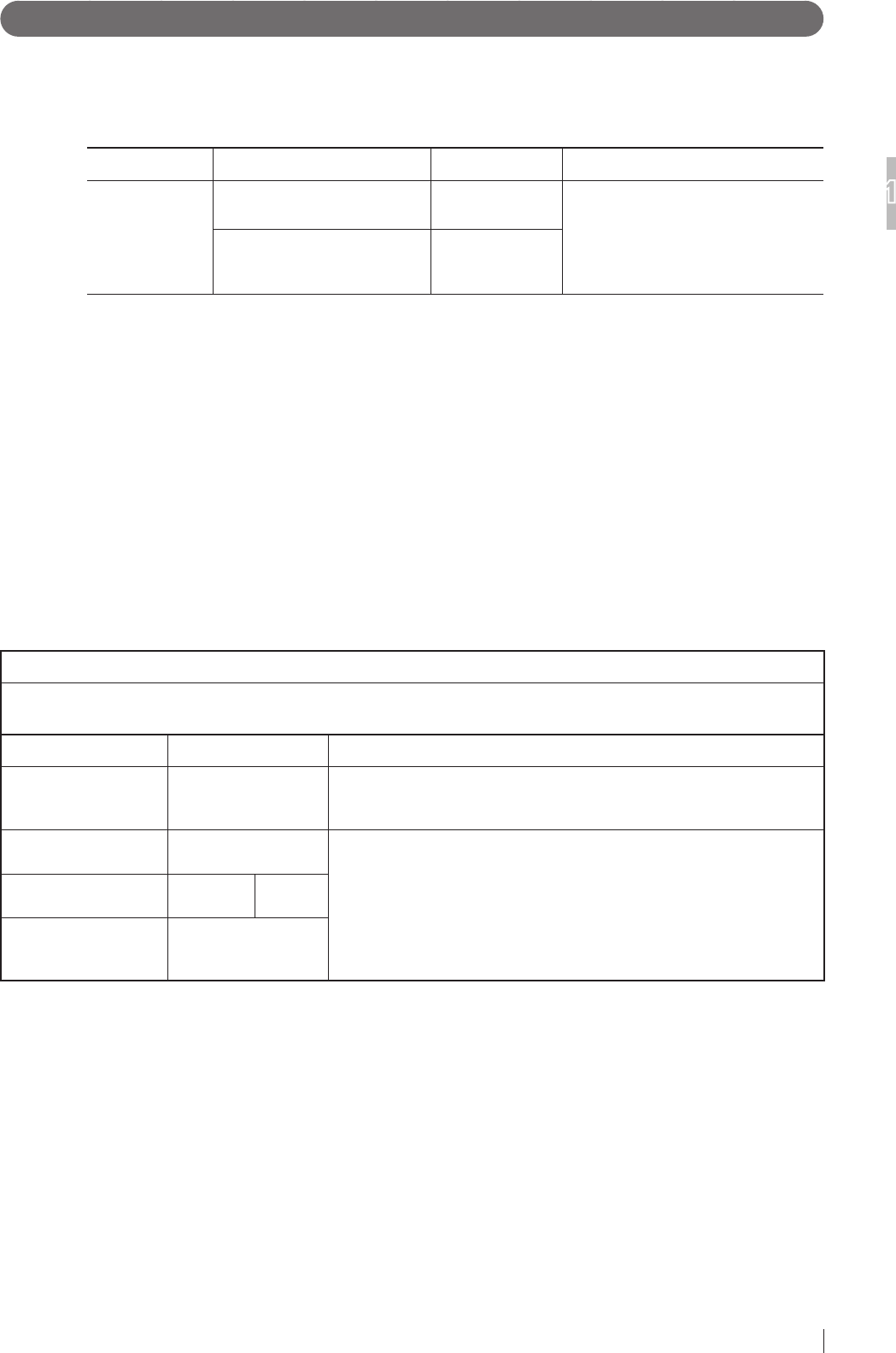
Name Connected Device Maximum Length General Specication
Network Cable Between the RICMP
and the RICMC
20m (65.6 ft) Cat5e or more,
UTP type and straight cable
Between the RICPB
and the Image processing
unit *
2m (6.56 ft)
* When the distance between the RICPB and the RICMC is 2 meters or more, install a commercially
available HUB. In that case, use a cable with a maximum length of 2 meters between the RICPB and HUB,
and a cable with a maximum length of 20 meters between HUB and the RICMC.
4. The use of accessories, transducers and cables other than those specied, with the exception
of transducers and cables sold by INNOLUX Corporation as replacement parts for internal
components, may result in increased emissions or decreased immunity of the RIC.
5. The RIC should not be used adjacent to or stacked with other equipment.
If adjacent or stacked use is necessary, the RIC should be observed to verify normal operation in
the conguration in which it will be used.
6. Basic performance of the equipment and the system
After image data are acquired from the at panel sensor, data correction is performed by the control
cabinet, and the image is saved in and displayed on the image processing unit.
7. Test items (Tables 1 to 4)
Table 1
Guidance and manufacturer’s declaration - electromagnetic emissions
The RIC is intended for use in the electromagnetic environment specied below.
The customer or the user of the RIC should assure that they are used in such an environment.
Emissions test Compliance Electromagnetic environment - guidance
RF emissions
CISPR 11 Group 1
The RIC uses RF energy only for their internal function.
Therefore, their RF emissions are very low and are not likely to cause
any interference in nearby electronic equipment.
RF emissions
CISPR 11 Class B
The RIC is suitable for use in all establishments, including domestic
establishments and those directly connected to the public low-voltage
power supply network that supplies buildings used for domestic
purposes.
Harmonic emissions
IEC 61000-3-2 Complies Class B
Voltage uctuations/
icker emissions
IEC 61000-3-3
Complies

1-10
For Safe Operation
1
Flat Panel Sensors Operation Manual 897N200608
Table 2
Guidance and manufacturer’s declaration - electromagnetic immunity
The RIC is intended for use in the electromagnetic environment specied below.
The customer or the user of the RIC should assure that they are used in such an environment.
Immunity test IEC 60601-1-2
test level Compliance level Electromagnetic environment -
guidance
Electrostatic
discharge
(ESD)
IEC 61000-4-2
±6kV contact
±8kV air
±6kV contact
±8kV air
Floors should be wood, concrete or
ceramic tile. If oors are covered with
synthetic material, the relative humidity
should be at least 30%.
Electrical fast
transient/burst
IEC 61000-4-4
±2kV for power supply
lines
±1kV for input/output
lines
±2kV for power supply
lines
±1kV for input/output
lines
Mains power quality should be that
of a typical commercial or hospital
environment.
Surge
IEC 61000-4-5
±1kV line(s) to line(s)
±2kV line(s) to earth
±1kV line(s) to line(s)
±2kV line(s) to earth
Mains power quality should be that
of a typical commercial or hospital
environment.
Voltage dips, short
interruptions and
voltage variations on
power supply input
lines
IEC 61000-4-11
<5% UT
(>95% dip in UT)
for 0.5 cycle
40% UT
(60% dip in UT)
for 5 cycles
70% UT
(30% dip in UT)
for 25 cycles
<5% UT
(>95% dip in UT)
for 5 s
<5% UT
(>95% dip in UT)
for 0.5 cycle
40% UT
(60% dip in UT)
for 5 cycles
70% UT
(30% dip in UT)
for 25 cycles
<5% UT
(>95% dip in UT)
for 5 s
Mains power quality should be that
of a typical commercial or hospital
environment. If the user of the RIC
requires continued operation during
power mains interruptions, it is
recommended that the RIC be powered
from an uninterruptible power supply or a
battery.
Power frequency
(50/60Hz) magnetic
eld
IEC 61000-4-8
3 A/m 3 A/m
Power frequency magnetic elds should
be at levels characteristic of a typical
location in a typical commercial or
hospital environment.
NOTE: UT is the a.c. mains voltage prior to application of the test level.
1-11
For Safe Operation
1
Flat Panel Sensors Operation Manual 897N200608
Table 3
Guidance and manufacturer’s declaration - electromagnetic immunity
The RIC is intended for use in the electromagnetic environment specied below.
The customer or the user of the RIC should assure that they are used in such an environment.
Immunity test IEC 60601-1-2
test level
Compliance level Electromagnetic environment - guidance
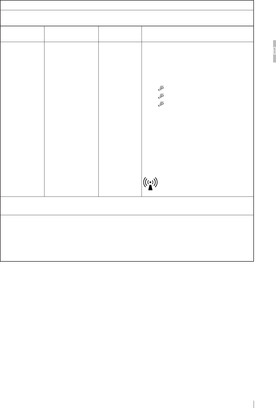
Conducted RF
IEC 61000-4-6
Radiated RF
IEC 61000-4-3
3 Vrms
150 kHz to 80 MHz
3 V/m
80 MHz to 2.5 GHz
3 Vrms
3 V/m
Portable and mobile RF communications equipment
should be used no closer to any part of the RIC,
including cables, than the recommended separation
distance calculated from the equation applicable to
the frequency of the transmitter.
Recommended separation distance
d = 1.2
d = 1.2 80 MHz to 800 MHz
d = 2.3 800 MHz to 2.5 GHz
where
P
is the maximum output power rating of the
transmitter in watts (W) according to the transmitter
manufacturer and
d
is the recommended separation
distance in metres (m).
Field strengths from xed RF transmitters, as
determined by an electromagnetic site survey,a
should be less than the compliance level in each
frequency range.b
Interference may occur in the vicinity of equipment
marked with the following symbol:
NOTE 1: At 80 MHz and 800 MHz, the higher frequency range applies.
NOTE 2: These guidelines may not apply in all situations. Electromagnetic propagation is affected by absorption and
reection from structures, objects and people.
a Field strength from xed transmitters, such as base stations for radio (cellular/cordless) telephones and land
mobile radios, amateur radio, AM and FM radio broadcast and TV broadcast cannot be predicted theoretically with
accuracy. To assess the electromagnetic environment due to xed RF transmitters, an electromagnetic site survey
should be considered. If the measured eld strength in the location in which the RIC is used exceeds the applicable
RF compliance, the RIC should be observed to verify normal operation. If abnormal performance is observed,
additional measures may be necessary, such as reorienting or relocating the RIC.
b Over the frequency range 150 kHz to 80 MHz, eld strength should be less than 3 V/m.

1-12
For Safe Operation
1
Flat Panel Sensors Operation Manual 897N200608
Table 4
Recommended separation distances between
Portable and mobile RF communications equipment and the RIC
The RIC is intended for use in the electromagnetic environment in which radiated RF disturbances are controlled.
The customer or the user of the RIC can help prevent electromagnetic interference by maintaining a minimum distance
between portable and mobile RF communications equipment (transmitters) and the RIC as recommended below,
according to the maximum output power of the communications equipment.
Rated maximum output
power of transmitter
W
Separation distance according to frequency of transmitter
m
150 kHz to 80 MHz
d = 1.2
80 MHz to 800 MHz
d = 1.2
800 MHz to 2.5 GHz
d = 2.3
0.01 0.12 0.12 0.23
0.1 0.38 0.38 0.73
1 1.2 1.2 2.3
10 3.8 3.8 7.3
100 12 12 23
For transmitters rated at a maximum output power not listed above, the recommended separation distance
d
in metres
(m) can be estimated using the equation applicable to the frequency of the transmitter, where
P
is the maximum output
power rating of the transmitter in watts (W) according to the transmitter manufacturer.
NOTE 1: At 80 MHz and 800 MHz, the separation distance for the higher frequency range applies.
NOTE 2: These guidelines may not apply in all situations.
Electromagnetic propagation is affected by absorption and reection from structures, objects and people.
2-1
System Configuration (Product Overview)
2
Flat Panel Sensors Operation Manual 897N200608
Chapter 2 System Configuration
(Product Overview)
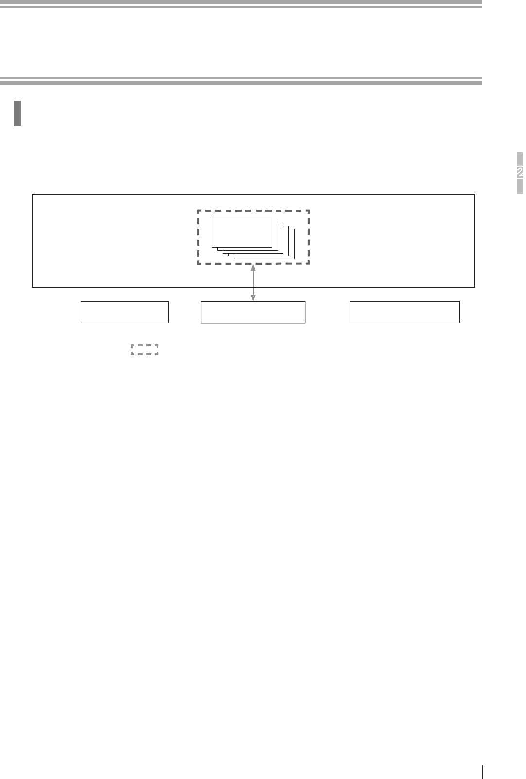
2.1 Flat Panel Sensor
2.1.1 System Con guration
Battery charger
Flat panel
sensor
Access point Image processing unit
DIGITAL RADIOGRAPHY RIC
• The products in can be installed in patient environment.
• Up to ve at panel sensors can be connected.
• The RICMC is installed on the image processing unit.
For the image collecting console, see the System Operation Manual.
2-2
System Configuration (Product Overview)
2
Flat Panel Sensors Operation Manual 897N200608
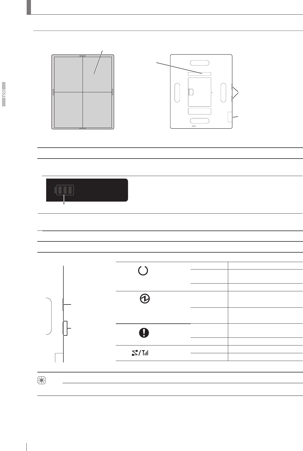
2.2 Names and the Functions
Names and the functions of the at panel sensor are described below.
Applied part
Flat panel sensor
* Exposure plane is shown in this figure.
Status lamp
Battery pack
level indicator
Connector for wired
communication
<Front> <Back>
Name Description
Flat panel sensor The RIC 35G and RIC 43G incorporate a GOS indirect panel.
The RIC 35C, RIC 43C and RIC 24C incorporate a CsI indirect panel.
Battery pack level indicator
Connector for wired
communication
Only the dedicated power supply unit specied by our ofcial dealer or
INNOLUX Representative can be connected.
Name Description
Status lamp
ERROR
POWER
READY
LINK
Indicates the equipment status by LEDs.
READY (Green)
On Exposure possible
Blinks for 1.0
second During exposure sequence
Off Not ready
POWER (Blue)
(The power on/off state of the
at panel sensor is displayed.).
On Power ON
Off Power OFF
ERROR (Orange)
Blinks for 1.0
second Error occurred
Off Normal
LINK (White) On Connected
Off Communication not possible.
* When the battery pack is not attached, all LEDs are off.
HINT
For details on the battery pack level indicator, see “3.1.6 Lamp Indications on the Flat Panel Sensor”.
2-3
System Configuration (Product Overview)
2
Flat Panel Sensors Operation Manual 897N200608
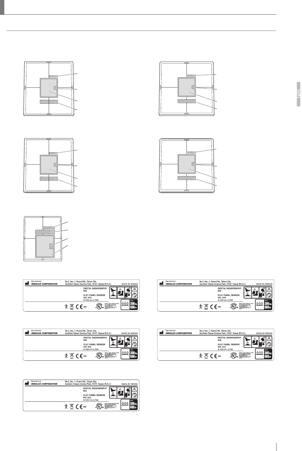
2.3 Locations of Labels and Signs
Locations of labels and signs afxed to each at panel sensor, and the relevant safety signs are shown below.
2.3.1 Locations of Labels
Serial Number Label
RIC 24C Identification Label
RIC 24C Cation Label
Battery Cover Label
<Exposure plane>
Flat panel sensor (RIC 24C)
Serial Number Label
RIC 35G Caution Label
Battery Cover Label
RIC 35G Identification Label
<Exposure plane>
Flat panel sensor (RIC 35G)
Serial Number Label
RIC 43G Caution Label
Battery Cover Label
RIC 43G Identification Label
<Exposure plane>
Flat panel sensor (RIC 43G)
Serial Number Label
RIC 35C Caution Label
Battery Cover Label
RIC 35C Identification Label
<Exposure plane>
Flat panel sensor (RIC 35C)
Serial Number Label
RIC 43C Caution Label
Battery Cover Label
RIC 43C Identification Label
<Exposure plane>
Flat panel sensor (RIC 43C)
RIC 35G Identification Label RIC 43G Identification Label
RIC 35C Identification Label RIC 43C Identification Label
RIC 24C Identification Label
2-4
System Configuration (Product Overview)
2
Flat Panel Sensors Operation Manual 897N200608
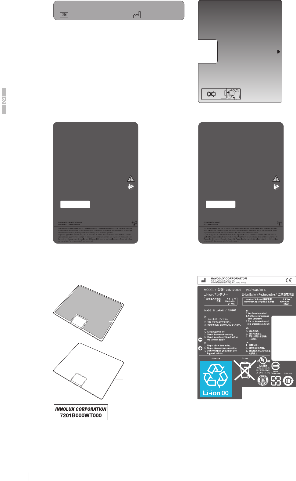
RIC 35G/RIC 43G/RIC 35C/RIC 43C
Caution Label
RIC 24C Caution Label
Battery Cover Label
S
N
Serial Number Label
SE Battery
Dummy Cover
Identification Label
SE Battery Dummy Cover
Identification Label
Battery pack (optional)
Battery pack
Rating Label
Battery Pack Rating Label
* The label varies, depending on the battery pack.
2-5
System Configuration (Product Overview)
2
Flat Panel Sensors Operation Manual 897N200608
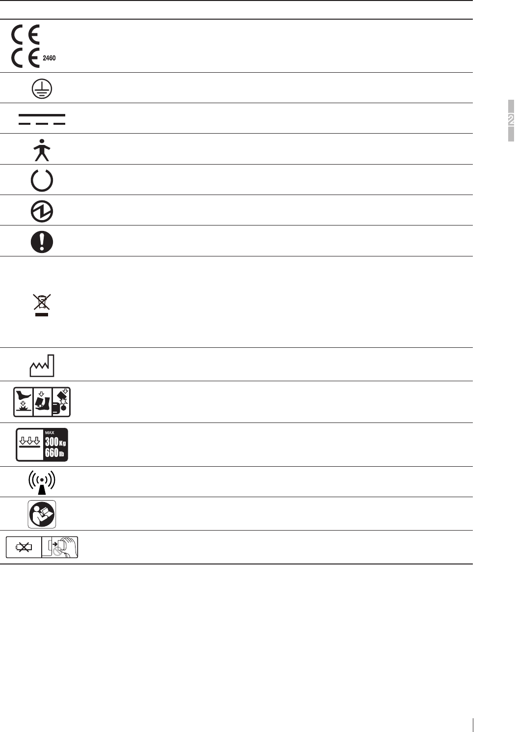
2.3.2 Safety and Other Symbols
The following safety symbols are used in the labels or on its body.
Symbol Description
CE marking
Protective earth (ground)
Direct current
This symbol indicates that the equipment is a Type B Applied Part.
Ready (To indicate the machine is ready for operation.)
Electric energy
General mandatory action sign
This symbol indicates that this product is not to be disposed of with your household waste, according
to the WEEE Directive (2002/96/EC) and your national law. This product should be handed over to a
designated collection point.
Improper handling of this type of waste could have a possible negative impact on the environment
and human health due to potentially hazardous substances that are generally associated with EEE.
At the same time, your cooperation in the correct disposal of this product will contribute to the
effective usage of natural resources.
For more information about waste, please contact our ofcial dealer or INNOLUX Representative.
Year of manufacture
Caution for local load / Do not drop the at panel sensor to the user/patient
Entire surface load
This symbol includes RF transmitters or indicates equipment that intentionally applies RF
electromagnetic energy for diagnosis or treatment.
Refer to Instruction Manual/Booklet
This symbol indicates that the part is not a battery.
This symbol instructs the user not to disconnect the SE cable during use.
2-6
System Configuration (Product Overview)
2
Flat Panel Sensors Operation Manual 897N200608
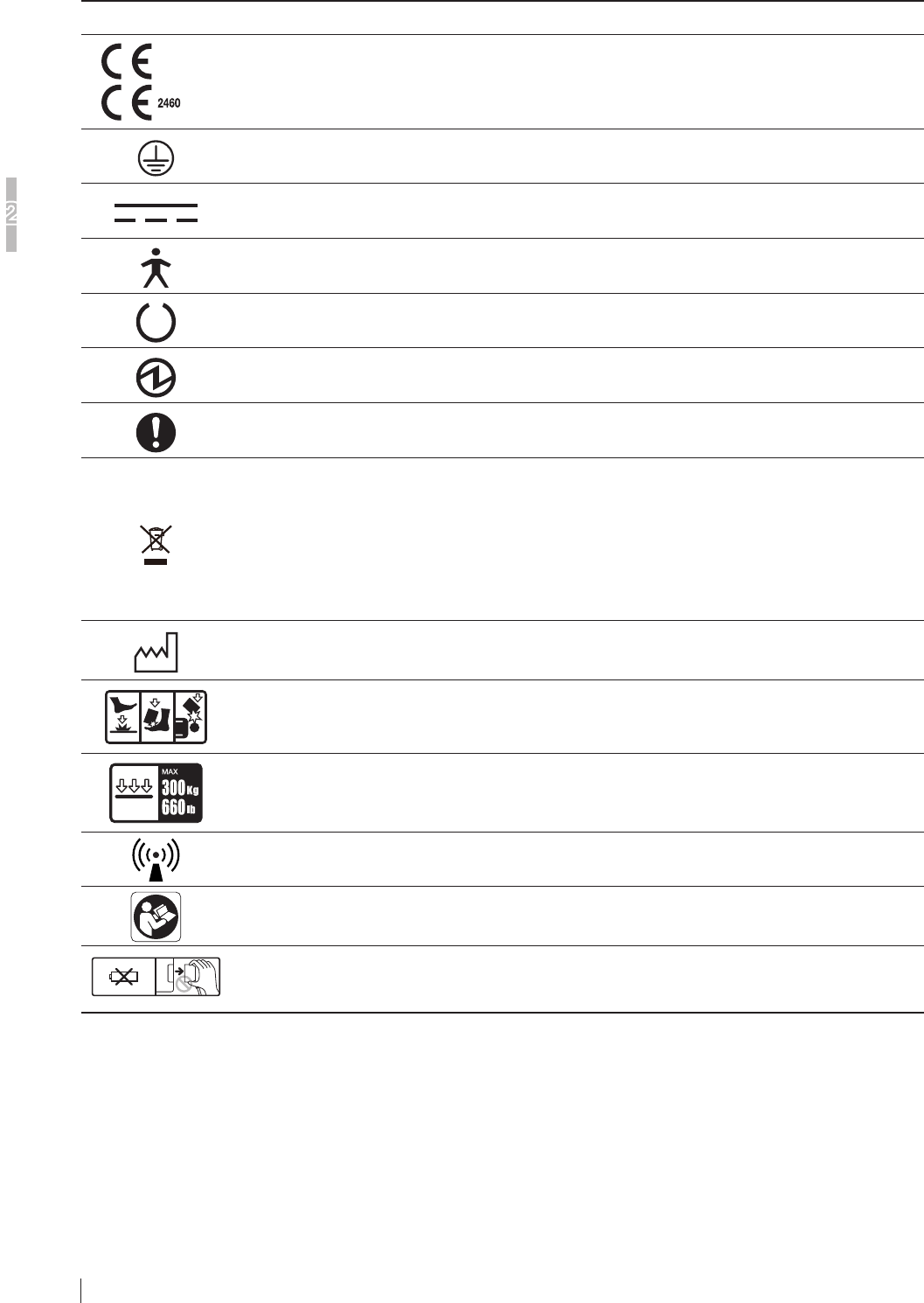
2.3.3 Symboles de sécurité et autres
Les symboles de sécurité suivants sont utilisés sur les étiquettes ou sur le corps de l’équipement.
Symbole Description
Marquage CE
Protection via mise à la terre (masse)
courant continu
Ce symbole indique que l’équipement est une pièce appliquée de type B.
Prêt (Pour indiquer que la machine est prête à être utilisée.)
Énergie électrique
Symbole général d’action obligatoire
Ce symbole indique que ce produit ne doit pas être mis au rebut avec les déchets ménagers, conformément à
la directive DEEE (2002/96/CE) et à la législation nationale en vigueur. Ce produit doit être remis à un centre
de collecte approprié.
Une manipulation incorrecte de ce type de déchet peut avoir un impact négatif sur l’environnement et sur la
santé humaine, en raison des substances potentiellement dangereuses généralement associées aux EEE.
Votre coopération pour la mise au rebut correcte de ce produit contribuera en outre à une utilisation efcace
des ressources naturelles.
Pour en savoir plus sur les déchets, contactez notre revendeur agréé ou notre représentant INNOLUX.
Année de fabrication
Attention relative à une charge placée de façon localisée /
Ne faites pas tomber le détecteur à panneau plat sur l’utilisateur/le patient
Charge sur l’intégralité de la surface
Ce symbole inclut les émetteurs RF ou indique un équipement émettant intentionnellement de
l’énergie électromagnétique RF à des ns de diagnostic ou de traitement.
Consultez le mode d’emploi
Ce symbole indique que la pièce n’est pas une batterie.
Ce symbole indique à l’utilisateur de ne pas débrancher le câble de branchement d’abonné
pendant l’utilisation.
3-1
Basic Operation
3
Flat Panel Sensors Operation Manual 897N200608
Chapter 3 Basic Operation
3.1 Preparing the Flat Panel Sensor
This section describes how to prepare the at panel sensor.
3.1.1 Type of Flat Panel Sensor
RIC 35G, RIC 43G, RIC 35C, RIC 43C, RIC 24C
The battery pack (optional) is required when the at panel sensor is used in wireless communication
mode.
3.1.2 Number of the Connectable Flat Panel Sensors
To enable the at panel sensor, its ID needs to be registered in advance by our ofcial dealer or
INNOLUX Representative.
Up to a hundred at panel sensors can be registered.
Up to ve at panel sensors can be connected.
3.1.3 Inserting/Removing the Flat Panel Sensor into/from the
Radiographic Examination Stand
Follow the procedure below to insert/remove the at panel sensor into/from the radiographic
examination stand.
For details, see the Operation Manual for the radiographic examination stand
CAUTIONS
For the positioning at the time of inserting/removing the at panel sensor, see the Operation
Manual for the radiographic examination stand.
CAUTIONS
Make sure that the at panel sensor is installed in the radiographic examination stand securely.
CAUTIONS
Be careful not to have your ngers caught when inserting/removing the at panel sensor into/
from the radiographic examination stand.
CAUTIONS
When pulling out/pushing in the tray of the radiographic examination stand after setting the at
panel sensor on it, be careful not to drop the at panel sensor or damage the tray.
3-2
Basic Operation
3
Flat Panel Sensors Operation Manual 897N200608
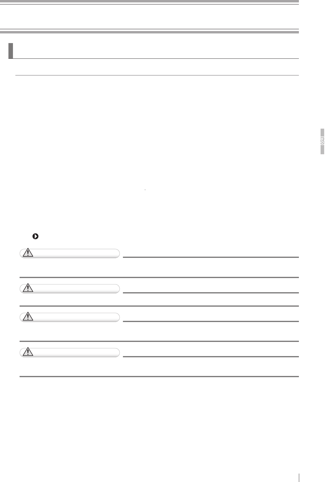
CAUTIONS
Before inserting/removing the at panel sensor into/from the radiographic examination stand,
pull out the tray completely. Otherwise, the at panel sensor may be damaged.
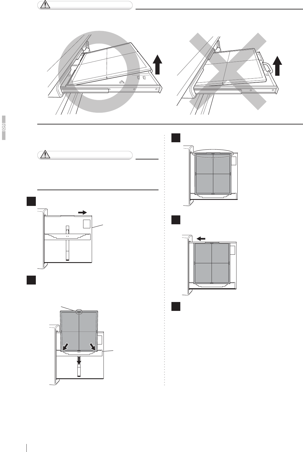
[1] Upright type
CAUTIONS
When inserting the at panel sensor into
the radiographic examination stand, direct
the exposure plane toward the X-ray tube.
1 Pull out the tray.
Tray
2
Insert the at panel sensor into the cassette
receive with the green mark of the at panel
sensor up, and then move it downwards.
Cassette receive
Green mark
3
Set the at panel sensor to the upper part of the tray.
4 Push the tray back into place after setting
the at panel sensor.
5 Remove the at panel sensor after use.
Pull out the tray, push the cassette receive
downwards, and then remove the at panel sensor.
Push the tray back into place.
3-3
Basic Operation
3
Flat Panel Sensors Operation Manual 897N200608
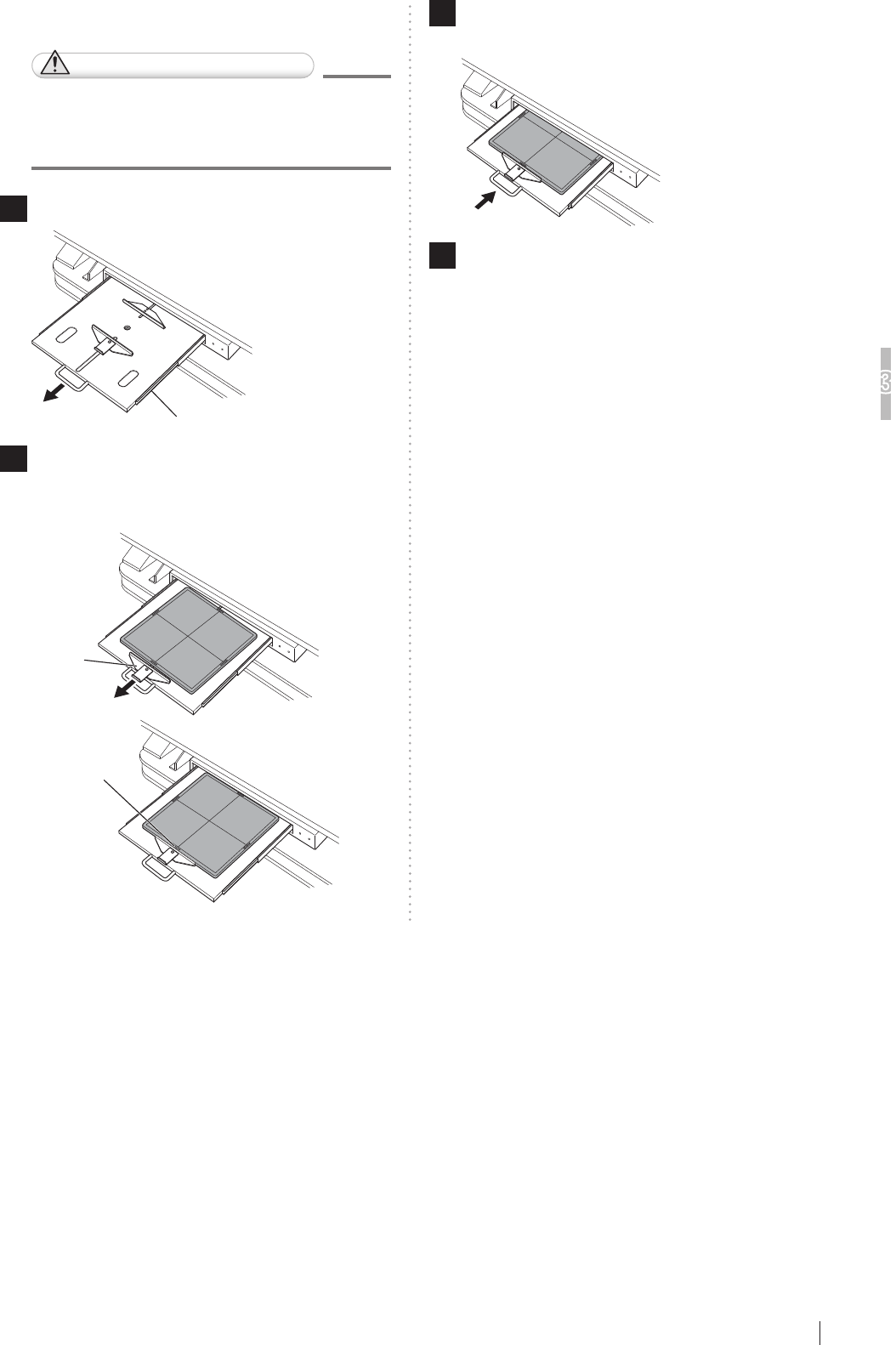
[2] Bed type
CAUTIONS
When inserting the at panel sensor
to the radiographic examination stand,
direct the exposure plane upwards.
1 Pull out the tray by using the handle.
Tray
2 Pull the cassette stopper, and set the at
panel sensor so that its center mark is
aligned with the center of the stopper.
Cassette
stopper
Center mark
3 Push the tray back into place by using the
handle after setting the at panel sensor.
4 Remove the at panel sensor after use.
Hold the handle and pull out the tray. Remove the
at panel sensor while pulling the cassette stopper,
and then push the tray back into place.
3.1.4 Charging the Battery Pack for the Flat Panel Sensor
Use the battery charger recommended by INNOLUX Corporation.
For details on operations, refer to the instruction manual for the battery charger.
3-4
Basic Operation
3
Flat Panel Sensors Operation Manual 897N200608
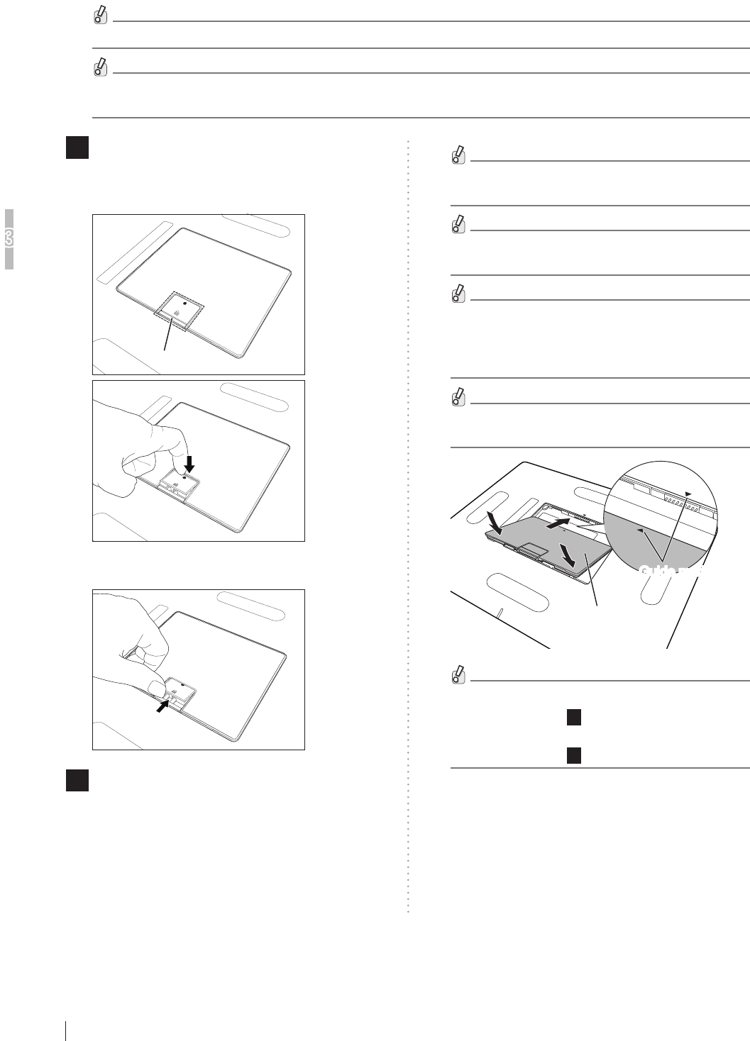
1 Remove the battery cover.
Place the at panel sensor with the back side facing
upward and press the “●” portion of the lock lever.
Lock lever
Slide the lock lever in the direction of the arrow to
remove the battery cover.
2 Install the battery pack.
Slide the battery pack along the dent of the battery
section of the at panel sensor toward the connector
terminal. Align the guide mark of the battery pack
with that of the at panel sensor, and push the
battery pack in to install it.
Make sure that battery pack is securely installed.
When installing the battery pack, do not press the
lock lever.
Pushing the battery pack in with the guide marks
misaligned may damage the connector terminal.
When attaching the battery pack, make sure that
the waterproof packing attached to the connector
terminal of the at panel sensor is aligned
properly.
When the battery pack is installed in the at panel
sensor, the power is automatically turned on.
Battery pack
Guide marksGuide marks
• To remove the battery pack, perform the same
procedure as Step
1
(removing the battery cover).
• To install the battery cover, perform the same
procedure as Step
2
(installing the battery pack).
3.1.5
Installing/Removing the Battery Pack for the Flat Panel
Sensor
Follow the procedure below to install/remove the battery pack for the at panel sensor.
When installing/removing the battery pack, place the at panel sensor on a at place.
Do not remove the battery pack until a processed image appears in the window of the image processing unit after
the exposure.

3-5
Basic Operation
3
Flat Panel Sensors Operation Manual 897N200608
3.1.6 Lamp Indications on the Flat Panel Sensor
This section explains the indications of the battery pack level indicator. For other lamp indications,
see “2.2 Names and the Functions”.
■ Battery pack level indicator
(When the battery pack is being charged)
Fully charged, available time of the at panel sensor:
More than 3 hours
LED1, 2, 3: Lit in green
Available time of the at panel sensor:
60 minutes or more
LED3: Blinking in green, LED1, 2: Lit in green
Available time of the at panel sensor:
30 minutes or more but less than 60 minutes
LED2: Blinking in green, LED1: Lit in green
Available time of the at panel sensor:
Less than 30 minutes
LED1: Blinking in green
(When the battery pack is not charged)
Available time of the at panel sensor:
60 minutes or more
LED1, 2, 3: Lit in green
Available time of the at panel sensor:
20 minutes or more but less than 60 minutes
LED1, 2: Lit in green
Available time of the at panel sensor:
Less than 20 minutes
LED1: Lit in green
Available time of the at panel sensor:
10 minutes or less
LED0: Lit in orange
LED3 LED2 LED1
LED0

3-6
Basic Operation
3
Flat Panel Sensors Operation Manual 897N200608
3.2 Starting Up and Shutting Down the
Flat Panel Sensor
This section explains how to start up and shut down the Flat Panel Sensor.
3.2.1 Starting Up
1 Attach a fully charged battery pack to the at panel sensor.
The POWER status lamp on the at panel sensor is lit in blue.
Start up the at panel sensor with the initial settings properly made by our ofcial dealer or INNOLUX Representative.
3.2.2 Performing an Exposure
1
When performing an exposure, make sure that the READY status lamp on the at panel sensor is lit.
3.2.3 Shutting Down
1 Remove the battery pack from the at panel sensor and set the battery pack in the battery charger.
The POWER status lamp on the at panel sensor is lit.
4-1
Daily Inspection and Maintenance
4
Flat Panel Sensors Operation Manual 897N200608
Chapter 4 Daily Inspection and
Maintenance
4.1 Daily User Inspection and Maintenance
During maintenance and inspection, strictly observe precautions contained in “Chapter 1 For Safe
Operation” in this manual for you to use the at panel sensor under best conditions.
4.1.1 Periodical Inspection
Inspection Every Three Months
Once every three months, remove any dirt or dust accumulated in each part of the equipment using
a vacuum cleaner or air duster, clean each part with a slightly moistened soft cloth and then wipe off
any moisture with a dry cloth.
See “2.2 Names and the Functions” (page 2-2).
CAUTIONS
Be sure to turn off the power before cleaning each part of the device.
No. Unit
1Flat panel sensor
CAUTIONS
Ensure sufcient space when cleaning the equipment on a table, etc.

4-2
Daily Inspection and Maintenance
4
Flat Panel Sensors Operation Manual 897N200608

A-1
Appendix A Specifications
Flat Panel Sensors Operation Manual 897N200608
Appendix A Specifications
A.1 Specifications
Specications of the at panel sensor are shown below.
A.1.1 Reduced Equivalent (Flat Panel Sensor)
Peak reduced equivalent on the front panel of the at panel sensor: 0.5 mmAl
A.1.2 Power Supply Conditions
Rated voltage : 6-12V
Input current : 2.73A
A.1.3 Environmental Conditions
(1) Operating Conditions
Temperature : 15°C (15%RH) - 30°C (80%RH)
Humidity : 15%RH (15°C) - 80%RH (30°C) (no dew condensation)
Atmospheric pressure : 700hPa - 1060hPa
(2) Non-operating Conditions
(Environmental conditions under which power can be supplied)
Temperature : 5°C - 35°C
Humidity : 10%RH - 80%RH (no dew condensation)
Atmospheric pressure : 700hPa - 1060hPa
(3) Storage Conditions
Temperature : -30°C - 50°C
Humidity : 10%RH - 90%RH (no dew condensation)
Atmospheric pressure : 700hPa - 1060hPa
CAUTIONS
When the at panel sensor is used in high temperature condition for long period of time, it may
cause image artifacts and/or failure of the device.
A-2
Appendix A Specifications
Flat Panel Sensors Operation Manual 897N200608
A.1.4 Image Performance
Each at panel sensor complies with IEC 62220-1 (MEDICAL ELECTRICAL EQUIPMENT -
CHARACTERISTICS OF DIGITAL X-RAY IMAGING DEVICES - ) as a general X-ray radiography
equipment.
To ensure optimal image quality, it is recommended that you do not use the at panel sensor near
devices (motor, transformer, switching supply, etc.) that generate electromagnetic noise.
A.1.5 Load Restriction
Entire surface load :
RIC 35G, RIC 43G, RIC 35C, RIC 43C, RIC 24C :
300kg (661.5 lb)
Local load :
RIC 35G, RIC 43G, RIC 35C, RIC 43C, RIC 24C :
120kg (264.6 lb) / ø40mm (1.6in.) (Based on INNOLUX measurement specications)
CAUTIONS
Do not apply an excessive force to the exposure plane.
The sensor inside the at panel sensor may be damaged, and it may not be possible to make
an exposure properly.
A.1.6 Radio Waves
The at panel sensor uses the following types of radio waves.
Flat panel sensor
Wireless specification IEEE802.11n
Transmit frequency 5.2, 5.3, 5.6, 5.8, 2.4 GHz
Modulation OFDM
Frequency tolerance ±20 ppm
Data transfer rate 35 Mbps
Transfer power 17 dBm or less
CAUTIONS
● Transmit frequencies available vary, depending on the country.
● Radio waves available outdoors vary, depending on the country where the system is used.
● When the RIC and any other wireless equipment are operating on the same frequency
channel in a hospital, it may take time to show an image on the image processing unit
monitor.
A-3
Appendix A Specifications
Flat Panel Sensors Operation Manual 897N200608
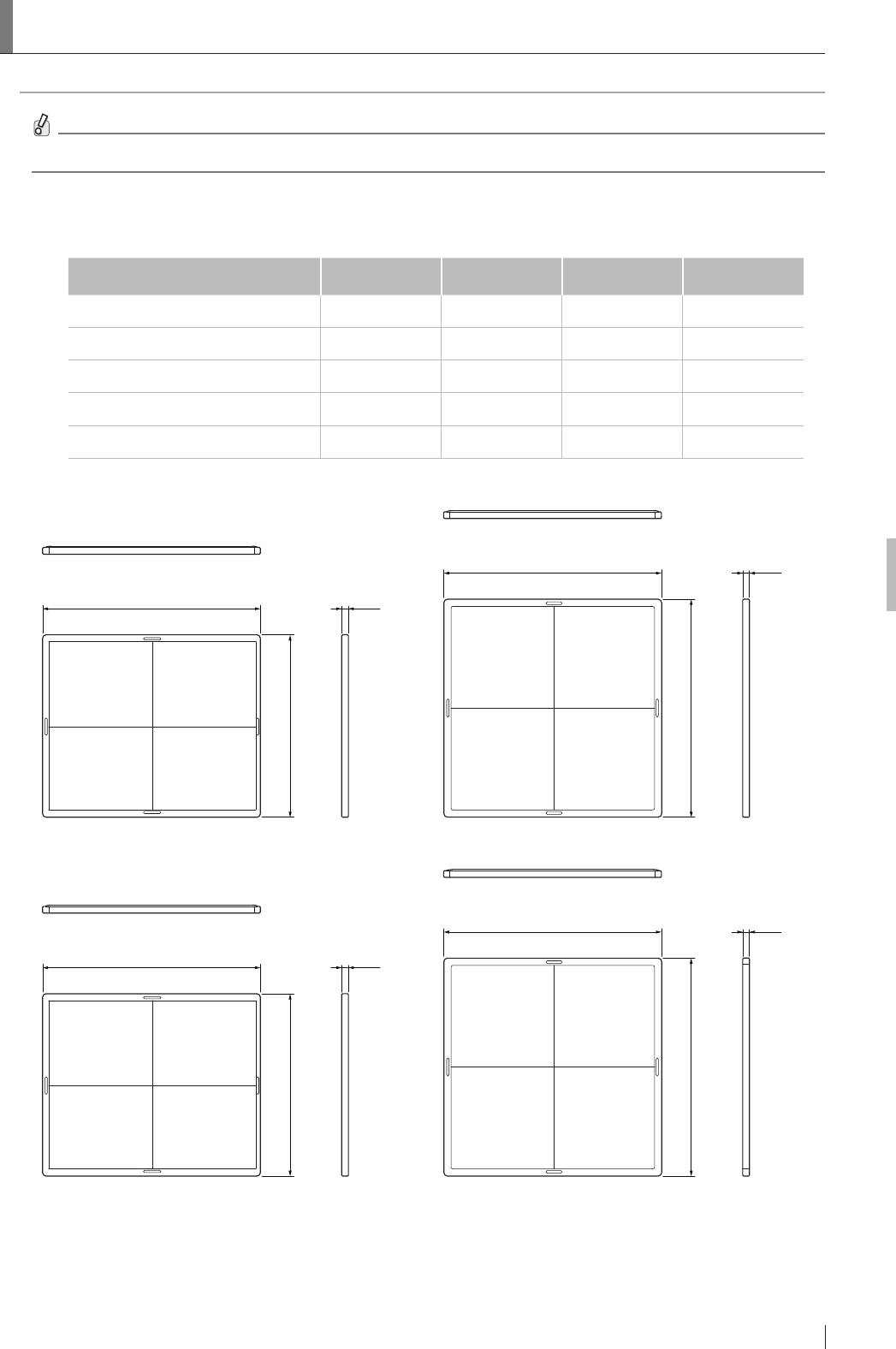
A.2 External View and Weight
The external view and weight of the each at panel sensor are shown below.
Specications, dimensions and weight are subject to change for improvement without prior notice.
A.2.1 Flat Panel Sensor
Width
(mm(in.))
Depth
(mm(in.))
Height
(mm(in.))
Weight
(kg(lb))
Flat panel sensor (RIC 35G) 460(18.1) 384(15.1) 15(0.6) 2.95(6.5)*1
Flat panel sensor (RIC 43G) 460(18.1) 460(18.1) 15(0.6) 3.65(8.0)*1
Flat panel sensor (RIC 35C) 460(18.1) 384(15.1) 15(0.6) 2.95(6.5)*1
Flat panel sensor (RIC 43C) 460(18.1) 460(18.1) 15(0.6) 3.65(8.0)*1
Flat panel sensor (RIC 24C) 328(13.0) 268(10.6) 15(0.6) 1.5(3.3)*1
*1 The weight of the battery pack is included.
15(0.6)460(18.1)
384(15.1)
Flat panel sensor (RIC 35G)
15(0.6)460(18.1)
460(18.1)
Flat panel sensor (RIC 43G)
Unit: mm(in.)
15(0.6)460(18.1)
460(18.1)
Flat panel sensor (RIC 43C)
15(0.6)460(18.1)
384(15.1)
Flat panel sensor (RIC 35C)
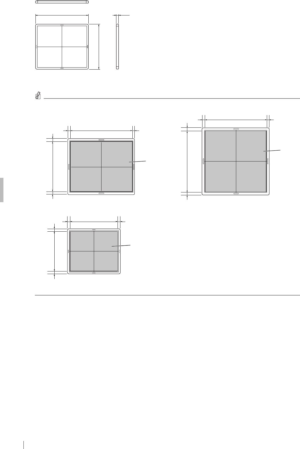
A-4
Appendix A Specifications
Flat Panel Sensors Operation Manual 897N200608
15(0.6)
328(13.0)
268(10.6)
Flat panel sensor (RIC 24C)
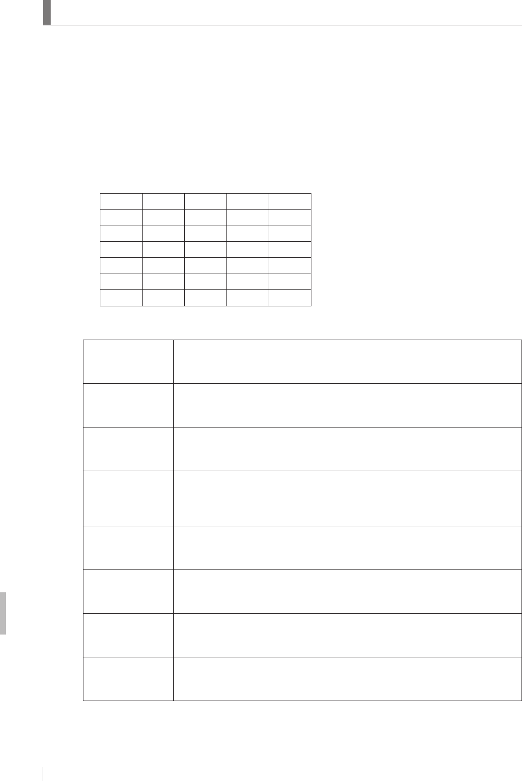
The effective area of the at panel sensor is as shown in the gure below.
20
(0.8)
20
(0.8)
288(11.3)
230.4(9.1)
17.45
(0.7)
20.45
(0.8)
Effective
area
RIC 24C
Effective
area
425.4(16.7) 17.25
(0.68)
17.25
(0.68)
16.75
(0.66)
16.75
(0.66) 350.4(13.8)
425.4(16.7) 17.25
(0.68)
17.25
(0.68)
Effective
area
17.55
(0.69)
17.55
(0.69) 424.8(16.7)
RIC 35G/RIC 35C RIC 43G/RIC 43C
Unit: mm(in.)

O-1
Appendix O Use of Optional Items
Flat Panel Sensors Operation Manual 897N200608
Appendix O Use of Optional Items
O.1 Optional Items
Name Description
Battery pack A battery pack for the at panel sensor.
For precautions, charging and installing/removing, see pages 1-4, 1-5, 1-6,
3-3 and 3-4.

O-2
Appendix O Use of Optional Items
Flat Panel Sensors Operation Manual 897N200608
Maintenance and Inspection
Flat Panel Sensors Operation Manual 897N200608
Maintenance and Inspection
1 Maintenance and Inspection Items Assigned to Specied Dealer
For periodical inspection of the equipment and necessary arrangements, consult our ofcial dealer
or local representative.
Periodical Maintenance
Make sure that the periodical maintenance and inspection assigned to our ofcial dealer or
INNOLUX Representative are performed as specied.
Maintenance and Inspection Items Assigned to Specied Dealer
Periodical Maintenance and Inspection Items Period
Checking of the image Every year
Checking of the operation record by referring to the error log Every year
Checking of the at panel sensor Every 2 years
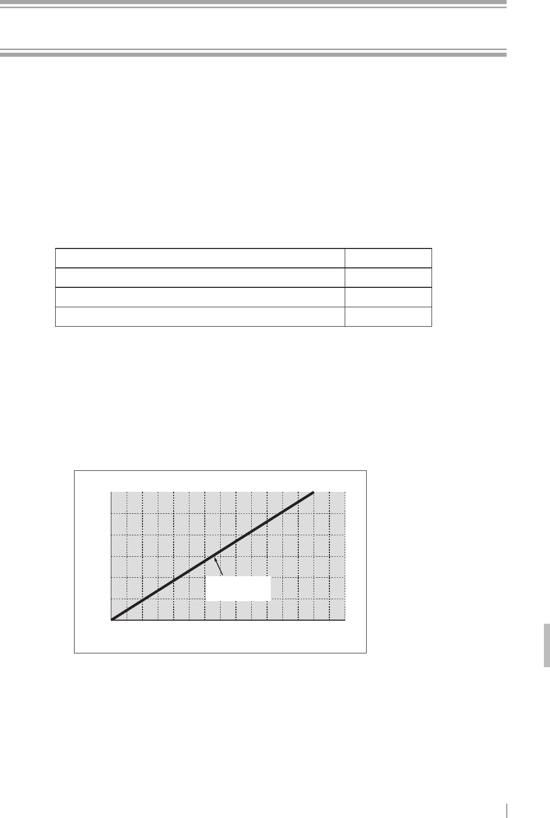
* It is recommended that the battery pack be replaced, if the battery storage capacity becomes
lower than 60%.
The battery pack should be replaced when the operable time is less than the following.
● RIC 35G/RIC 43G/RIC 35C/RIC 43C/RIC 24C :
100 minutes (1 hour and 40 minutes)
* Refer to the operable time displayed on the image processing unit when the battery pack is fully
charged and no exposure menu is registered.
* Depending on the usage environment, etc., the displayed time is slightly different from the
actual operable time.
(Reference) Time for battery pack replacement
Battery storage capacity [%]
Operable time [Minute]
120
100
80
6060
40
20
0
0 30 60 90 120 150 210 240180
Time for replacement:
Less than 100 minutes
(1 hour and 40 minutes)
The cycles of periodical maintenance and inspection and of parts replacement differ depending on
the usage and the daily operation time.
For details, contact our ofcial dealer or INNOLUX Representative.

Maintenance and Inspection
Flat Panel Sensors Operation Manual 897N200608
Radio frequency (RF) compliance information
Compliance with Part 15 of FCC Rules and
Industry Canada licence-exempt RSS standard(s).
This device complies with Part 15 of FCC Rules and Industry Canada’s licence-exempt RSSs.
Operation is subject to the following two conditions: (1) this device may not cause harmful interference,
and (2) this device must accept any interference received, including interference that may cause
undesired operation.
Le présent appareil est conforme à la partie 15 des règles de la FCC et aux normes des CNR d’Industrie
Canada applicables aux appareils radio exempts de licence. L’exploitation est autorisée aux deux
conditions suivantes : (1) l’appareil ne doit pas produire de brouillage, et (2) l’appareil doit accepter tout
brouillage subi, même si le brouillage est susceptible d’en compromettre le fonctionnement.
FCC CAUTION
Changes or modications not expressly approved by the party responsible for compliance could void the
user’s authority to operate the equipment.
The available scientic evidence does not show that any health problems are associated with using
low power wireless devices. There is no proof, however, that these low power wireless devices are
absolutely safe. Low power Wireless devices emit low levels of radio frequency energy (RF) in the
microwave range while being used. Whereas high levels of RF can produce health effects (by heating
tissue), exposure of low-level RF that does not produce heating effects causes no known adverse health
effects. Many studies of low-level RF exposures have not found any biological effects. Some studies
have suggested that some biological effects might occur, but such ndings have not been conrmed by
additional research. RIC 35G/RIC 43G/RIC 35C/RIC 43C/RIC 24C has been tested and found to comply
with FCC/IC radiation exposure limits set forth for an uncontrolled environment and meets the FCC radio
frequency (RF) Exposure Guidelines and RSS-102 of the IC radio frequency (RF) Exposure rules.
Les connaissances scientiques dont nous disposons n’ont mis en évidence aucun problème de santé
associé à l’usage des appareils sans l à faible puissance. Nous ne sommes cependant pas en mesure
de prouver que ces appareils sans l à faible puissance sont entièrement sans danger. Les appareils
sans l à faible puissance émettent une énergie fréquence radioélectrique (RF) très faible dans le
spectre des micro-ondes lorsqu’ils sont utilisés. Alors qu’une dose élevée de RF peut avoir des effets
sur la santé (en chauffant les tissus), l’exposition à de faibles RF qui ne produisent pas de chaleur n’a
pas de mauvais effets connus sur la santé. De nombreuses études ont été menées sur les expositions
aux RF faibles et n’ont découvert aucun effet biologique. Certaines études ont suggéré qu’il pouvait
y avoir certains effets biologiques, mais ces résultats n’ont pas été conrmés par des recherches
supplémentaires. RIC 35G/RIC 43G/RIC 35C/RIC 43C/RIC 24C a été testé et jugé conforme aux
limites d’exposition aux rayonnements énoncées pour un environnement non contrôlé et respecte les
règles les radioélectriques (RF) de la FCC lignes directrices d’exposition et d’exposition aux fréquences
radioélectriques (RF) CNR-102 de l’IC.
Compliance with FCC requirement 15.407(c) and IC requirment RSS-210 A9.4.4 Data transmission is
always initiated by software, which is the passed down through the MAC, through the digital and analog
baseband, and nally to the RF chip. Several special packets are initiated by the MAC. These are the
only ways the digital baseband portion will turn on the RF transmitter, which it then turns off at the end of
the packet. Therefore, the transmitter will be on only while one of the aforementioned packets is being
transmitted. In other words, this device automatically discontinue transmission in case of either absence
of information to transmit or operational failure.
Conformité à la norme CNR-210 A9.4.4 La transmission des données est toujours initiée par le logiciel,
puis les données sont transmises par l’intermédiaire du MAC, par la bande de base numérique et
analogique et, enn, à la puce RF. Plusieurs paquets spéciaux sont initiés par le MAC. Ce sont les seuls
moyens pour qu’une partie de la bande de base numérique active l’émetteur RF, puis désactive celui-ci
à la n du paquet. En conséquence, l’émetteur reste uniquement activé lors de la transmission d’un des
paquets susmentionnés. En d’autres termes, ce dispositif interrompt automatiquement toute transmission
en cas d’absence d’information à transmettre ou de défaillance.

Maintenance and Inspection
Flat Panel Sensors Operation Manual 897N200608
Radio waves in the 5.2GHz and 5.3GHz frequency bands can be used indoors only.
Les bandes de fréquences 5.2GHz et 5.3GHz ne peuvent être utilisées qu’en intérieur.
High-power radars are allocated as primary users (i.e. priority users) of the bands 5250-5350 MHz and
5650-5850 MHz and that these radars could cause interference and/or damage to LE-LAN devices.
Les radars de haute puissance sont designes comme utilisateurs principaux (c’est-a dire utilisateurs
prioritaires) pour les bandes 5250-5350 MHz et 5650-5850 MHz, et que ces radars peuvent provoquer du
brouillage et/ou des dommages aux dispositifs LAN-EL.
Frequency Tolerance : ±20ppm
(This transmitter must not be co-located or operated in conjunction with any other antenna or transmitter.)
Maintenance and Inspection
Flat Panel Sensors Operation Manual 897N200608
Compliance with 2014/53/EU
Manufacture’s Name: INNOLUX Corporation
Manufacture’s Address: No.3, Sec. 1, Huansi Rd., Tainan City, Southern Taiwan Science Park,
74147, Taiwan (R.O.C.)
declares that the product:
Model Number: RIC 35G, RIC 43G, RIC 35C, RIC 43C, RIC 24C
The product complies with the requirements of the RE Directive 2014/53/EU.
The shipment schedule country is as follows.
AT BE BG CH CY
CZ DE DK EE ES
FI FR GB GR HR
HU IE IS IT LI
LT LU LV MK MT
NL NO PL PT RO
SE SI SK TR
[BG]
Bulgarian
С настоящето, INNOLUX, декларира, че RIC 35G, RIC 43G, RIC 35C,
RIC 43C, RIC 24C е в съответствие със съществените изисквания и
другитеприложими разпоредби на Директива 2014/53/EC.
[CS]
Czech
INNOLUX tímto prohlašuje, že RIC 35G, RIC 43G, RIC 35C, RIC 43C, RIC
24C splňuje základní požadavky a všechna příslušná ustanoveni Směrnice
2014/53/EU.
[DA]
Danish
Undertegnede INNOLUX erklærer herved, at følgende udstyr RIC 35G,
RIC 43G, RIC 35C, RIC 43C, RIC 24C overholder de væsentlige krav og
øvrige relevante krav i direktiv 2014/53/EU.
[DE]
German
Hiermit erklärt INNOLUX, dass sich das Gerät RIC 35G, RIC 43G, RIC 35C,
RIC 43C, RIC 24C in Übereinstimmung mit den grundlegenden Anforderungen
und den übrigen einschlägigen Bestimmungen der Richtlinie 2014/53/EU
bendet.
[EN]
English
Hereby, INNOLUX, declares that this RIC 35G, RIC 43G, RIC 35C, RIC 43C,
RIC 24C is in compliance with the essential requirements and other relevant
provisions of Directive 2014/53/EU.
[ES]
Spanish
Por la presente, INNOLUX, declara que este RIC 35G, RIC 43G, RIC 35C,
RIC 43C, RIC 24C cumple con los requisitos esenciales y otras exigencias
relevantes de la Directiva 2014/53/UE.
[ET]
Estonian
Käesolevaga kinnitab INNOLUX seadme RIC 35G, RIC 43G, RIC 35C,
RIC 43C, RIC 24C vastavust direktiivi 2014/53/EL põhinõuetele ja nimetatud
direktiivist tulenevatele teistele asjakohastele sätetele.
[FI]
Finish
INNOLUX vakuuttaa täten että RIC 35G, RIC 43G, RIC 35C, RIC 43C, RIC 24C
tyyppinen laite on direktiivin 2014/53/EU oleellisten vaatimusten ja sitä koskevien
direktiivin muiden ehtojen mukainen.

Maintenance and Inspection
Flat Panel Sensors Operation Manual 897N200608
[FR]
French
Par la présente, INNOLUX déclare que l’appareil
RIC 35G, RIC 43G, RIC 35C,
RIC 43C, RIC 24C est conforme aux exigences essentielles et aux autres
dispositions pertinentes de la directive 2014/53/UE.
[EL]
Greek
ΜΕ ΤΗΝ ΠΑΡΟΥΣΑ Ο ΚΑΤΑΣΚΕΥΑΣΤΗΣ INNOLUX ΔΗΛΩΝΕΙ ΟΤΙ
RIC 35G, RIC 43G, RIC 35C, RIC 43C, RIC 24C ΣΥΜΜΟΡΦΩΝΕΤΑΙ ΠΡΟΣ
ΤΙΣ ΟΥΣΙΩΔΕΙΣ ΑΠΑΙΤΗΣΕΙΣ ΚΑΙ ΤΙΣ ΛΟΙΠΕΣ ΣΧΕΤΙΚΕΣ ΔΙΑΤΑΞΕΙΣ ΤΗΣ
ΟΔΗΓΙΑΣ 2014/53/EE
[HU]
Hungarian
A INNOLUX ezzennel kijelenti, hogy a
RIC 35G, RIC 43G, RIC 35C, RIC 43C,
RIC 24C
típusú beren-dezés teljesíti az alapvető követelményeket és más
2014/53/EU irányelvben meghatározott vonatkozó rendelkezéseket.
[HR]
Croatian
Ovime, INNOLUX, potvrđuje da je RIC 35G, RIC 43G, RIC 35C, RIC 43C,
RIC 24C u sukladnost sa osnovnim zahtjevima i drugim važnim odredbama
Direktive 2014/53/EU.
[IS]
Icelandic
Hér með lýsir INNOLUX yr því að RIC 35G, RIC 43G, RIC 35C, RIC 43C,
RIC 24C er í samræmi við grunnkröfur og aðrar kröfur, sem gerðar eru í
tilskipun 2014/53/EU
[IT]
Italian
Con la presente INNOLUX dichiara che questo RIC 35G, RIC 43G, RIC 35C,
RIC 43C, RIC 24C è conforme ai requisiti essenziali ed alle altre disposizioni
pertinenti stabilite dalla direttiva 2014/53/UE.
[LV]
Latvian
Ar šo INNOLUX deklarē, ka RIC 35G, RIC 43G, RIC 35C, RIC 43C, RIC 24C
atbilst Direktīvas 2014/53/ES būtiskajām prasībām un citiem ar to saistītajiem
noteikumiem.
[LT]
Lithuanian
Šiuo INNOLUX deklaruoja, kad šis RIC 35G, RIC 43G, RIC 35C, RIC 43C,
RIC 24C atitinka esminius reikalavimus ir kitas 2014/53/ES Direktyvos
nuostatas
[МК]
Macedonian
INNOLUX, изјавува дека овој RIC 35G, RIC 43G, RIC 35C, RIC 43C, RIC 24C
е во согласност со суштинските барања и други релевантни одредби на
Директивата 2014/53/EU.
[MT]
Maltese
Hawnhekk, INNOLUX, jiddikjara li dan RIC 35G, RIC 43G, RIC 35C, RIC 43C,
RIC 24C jikkonforma mal-ħtiġijiet essenzjali u ma provvedimenti oħrajn relevanti
li hemm d-Dirrettiva 2014/53/UE.
[NL]
Dutch
Hierbij verklaart INNOLUX dat het toestel l RIC 35G, RIC 43G, RIC 35C,
RIC 43C, RIC 24C in overeenstemming is met de essentiële eisen en de
andere relevante bepalin-gen van richtlijn 2014/53/EU.
[NO]
Norwegian
INNOLUX erklærer herved at utstyret RIC 35G, RIC 43G, RIC 35C, RIC 43C,
RIC 24C er i samsvar med de grunnleggende krav og øvrige relevante krav i
direktiv 2014/53/EU.
[PL]
Polish
Niniejszym INNOLUX deklaruje że RIC 35G, RIC 43G, RIC 35C, RIC 43C,
RIC 24C jest zgodny z zasadniczymi wymaganiami i innymi właściwymi
postanowieniami Dyrektywy 2014/53/UE.
[PT]
Portuguese
Eu, INNOLUX, declaro que o RIC 35G, RIC 43G, RIC 35C, RIC 43C, RIC 24C
cumpre os requisitos essenciais e outras provisões relevantes da Directiva
2014/53/UE.
[RO]
Romanian
Prin prezenta, INNOLUX, declară că aparatul RIC 35G, RIC 43G, RIC 35C,
RIC 43C, RIC 24C este în conformitate cu cerinţele esenţiale şi cu alte
prevederi pertinente ale Directivei 2014/53/UE.
[SK]
Slovak
INNOLUX týmto vyhlasuje, že RIC 35G, RIC 43G, RIC 35C, RIC 43C, RIC 24C
spĺňa základné požiadavky a všetky príslušné ustanovenia Smernice 2014/53/
EÚ.

Maintenance and Inspection
Flat Panel Sensors Operation Manual 897N200608
[SL]
Slovenian
INNOLUX izjavlja, da je ta RIC 35G, RIC 43G, RIC 35C, RIC 43C, RIC 24C
v skladu z bistvenimi zahtevami in drugimi relevantnimi določili direktive
2014/53/EU.
[SV]
Swedish
Härmed intygar INNOLUX, att denna RIC 35G, RIC 43G, RIC 35C, RIC 43C,
RIC 24C är förenligt med de grundläggande kraven och andra relevanta
bestämmelser i direktivet 2014/53/EU.
[TR]
Turkish
İşbu belge ile INNOLUX, bu RIC 35G, RIC 43G, RIC 35C, RIC 43C, RIC 24C
ürününün 2014/53/AB sayılı Yönerge’nin temel şartlarıyla ve diğer ilgili
hükümleriyle uyumlu olduğunu beyan eder.

Maintenance and Inspection
Flat Panel Sensors Operation Manual 897N200608
Innolux
EC Declaration of Conformity
Manufacturer :
Address :
Innolux Corporation
Product : RIC 35G, RIC 35C,
RIC 43G, RIC 43C,
RIC 24C
Model No. : RIC 35G, RIC 35C,
RIC 43G, RIC 43C,
RIC 24C
Applicable Product Units : Serial No. ***0001 or later
Control Software: 0X0221 or later
We, Innolux Corporation, herewith declare under our sole responsibility that the product(s) identified
in this declaration conforms to the provisions of the following Directive and Standards.
Directive :
RE Directive: 2014/53/EU
Standards :
SAR EN 62311:2008
Radio EN 300 328 V1.9.1
EN 301 893 V1.8.1
EMC EN 301 489-1 V1.9.2
EN 301 489-17 V2.2.1
Safety EN 60601-1:2006/A1:2013
Place and Date of issue
[Area], Tiwan
[date]
Signature :
Name :
Function :
Innolux Corporation

INNOLUX
No.3, Sec. 1, Huansi Rd., Tainan City, Southern Taiwan Science Park,
74147, Taiwan (R.O.C.)
INNOLUX Optoelectronics Europe B.V.
Jupiterstraat 106, 2132 HE Hoofddorp, The Netherlands
EU Importer
INNOLUX Optoelectronics Europe B.V.
Jupiterstraat 106, 2132 HE Hoofddorp, The Netherlands
INNOLUX MEDICAL SYSTEMS U.S.A., INC.
419 WEST AVENUE, STAMFORD CT 06902, U.S.A.