Fuji Film 02000001 INSTALL THE MODULE INTO A DIGITAL CAMERA IN MARKET User Manual S 190980 01E
Fuji Film Corporation INSTALL THE MODULE INTO A DIGITAL CAMERA IN MARKET S 190980 01E
USERS MANUAL
- 1 -
FZ09396-100
User’s Manual
Notice:
This device complies with Part 15 of FCC Rules and Industry Canada licence-exempt RSS
standard(s). Operation is subject to the following two conditions: (1) this device may not cause
interference, and (2) this device must accept any interference, including interference that may
cause undesired operation of this device.
Warning:
Changes or modifications not expressly approved by the party responsible for compliance could
void the user’s authority to operate the equipment.
This device is to be used only for mobile and fixed applications. The antenna(s) used for this
transmitter must be installed to provide a separation distance of at least 20cm from all persons
and must not be co-located or operating in conjunction with any other antenna or transmitter.
NOTE:
This equipment has been tested and found to comply with the limits for a Class B digital device,
pursuant to part 15 of the FCC Rules. These limits are designed to provide reasonable
protection against harmful interference in a residential installation.
This equipment generates, uses and can radiate radio frequency energy and, if not installed and
used in accordance with the instructions, may cause harmful interference to radio
communications. However, there is no guarantee that interference will not occur in a particular
installation. If this equipment does cause harmful interference to radio or television reception,
which can be determined by turning the equipment off and on, the user is encouraged to try to
correct the interference by one or more of the following measures:
Reorient or relocate the receiving antenna
Increase the separation between the equipment and receiver.
Connect the equipment into an outlet on a circuit different from that to which the receiver is
connected.
Consult the dealer or an experienced radio/TV technician for help
The host device shall also comply with the certification labeling requirements of each of the
modules it contains.
A reference to the enclosed module displaying its FCC and IC ID certification number.
Recommended wording:
* Contains FCC ID: W2Z-02000001
* Contains IC ID: 7736B-02000001
(1)
This products Standard shall be applied to the Wireless LAN module(DWM-W078)
本規格は、無線LANモジュール(DWM-W078)について規定する。
Contents.
No. No.
1 Product summary
1-1 Scope
1-2 General explanation
2Hardware specification
2-1 Block diagram
2-2 Environmental condition
2-3 Power supply
3 Electrical characteristics
3-1 Channel plan
3-2 Power Sequence
3-3 Interface specification
3-4 SDIO Protocol Timing
3-5 Current consumption
3-6 Antenna specification
3-7 Reciever characteristics
3-8 Transmitter characteristics
4Measurement method
4-1 Tx test condition
4-2 Rx test condition
5Mechanical specification
5-1 Dimension
5-2 Weight
5-3 Terminal number and name
6 Reliability Test
7Revision
MITSUMI ELECTRIC CO.,LTD.
14
12
12
13
11
12
12
4
4
S19
4
7
0980
2
3
3
7
8-10
4-10
DWM-W078 Formed on.
APPROVED BY CHECKED BY DESIGNED BY
Page
2
GROUP NO. DWG.NO.
2
Item Page Item
6
5
11
11
SYM.
2011.11.28
SPECIFICATON
3
3
MODEL:
技術部
町田
'11.11.28
技術部
'10.11.28
主幹 内田
技術部
'10.11.28
統括課長
和気
1
(
2
)
1.Product Summary
製品概要
1-1. Scope
2.4 GHz WLAN module with integrated antenna
(IEEE802.11 b/g/n supported)
2.4GHz帯 アンテナ一体 無線LANモジュール
(IEEE802.11 b/g/n 準拠)
1-2. General explanation
Standard IEEE802.11b/g/n
Frequency 2.4-2.4835GHz
Host Interfase SDIO ver2.0
Frequency Bandwidth 20MHz
Weight 0.5g typ
・Chipset: MARVELL Semiconductor Inc. 88W8787L(CPS Package)
・Modulation Types: DBPSK, DQPSK and CCK with 802.11b mode
OFDM(BPSK, QPSK, 16-QAM and 64-QAM) with 802.11g/n mode
・Data rate: 1,2,5.5 and 11 with 802.11b mode
6,9,12,18,24,36,48 and 54 with 802.11g mode
MCS0-7 with 802.11n mode
・Security: WEP(64 and 128bits), WPA-PSK(TKIP/AES) and WPA2-PSK(TKIP/AES)
MITSUMI ELECTRIC CO.,LTD.
DWG.NO.
0980 1
(
3
)
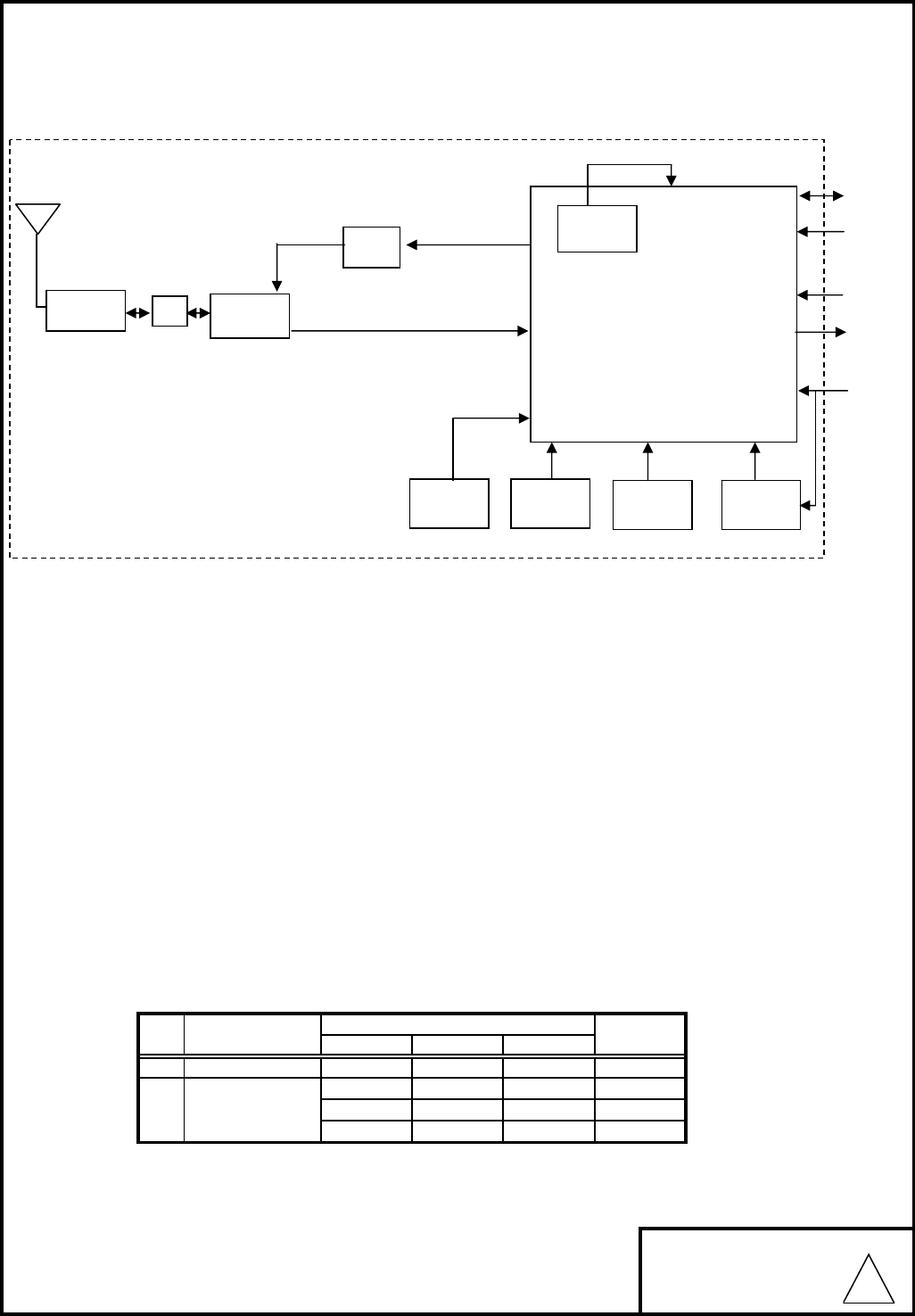
2.Hardware Specification
2-1. Block diagram
ブロック図
2-2. Environmental condition
環境条件
1) Operating environment
動作環境条件
Operating temperature range
動作温度範囲 : -20 ~ 70 ℃
Operating humidity range
動作湿度範囲 : 20%~80%(None dew) 結露無き事
2) Storage environment
保存環境条件
Storage temperature range
保存温度範囲 : -30 ~ 85 ℃
Storage humidity range
保存湿度範囲 : 20%~85%(None dew) 結露無き事
2-3. Power supply
1
MITSUMI ELECTRIC CO.,LTD.
2.70
3.63 V
V
DWG.NO.
0980
No Value
Symbol
2
2.97
1.98
VDD33 3.30
2.60
1.62
TYP.
VIO
2.97
1.80
MIN.
3.30
2.50
UNIT
MAX.
3.63
V
V
SDIO I/F
VDD33
Power
Amp
DPDT
RF Switch
RF TX
RF RX
MARVELL
88W8787 (CSP)
RF Switch
Connector
Anntena
LPF
+1.8V
LDO
38.4MHz
XTAL
88W8787L
PMU(1.2V)
Serial
EEPROM
VIO
32kHz
RTC Clock
Pdn
HostWakeup
1
(
4
)
3.Electrical Characteristics
電気的特性
3-1. Channel Plan チャンネルプラン
IEEE802.11b/g/n
(
HT20
)
2412 MHz 2437 MHz 2462 MHz
2417 MHz 2442 MHz 2467 MHz
2422 MHz 2447 MHz 2472 MHz
2427 MHz 2452 MHz
2432 MHz 2457 MHz
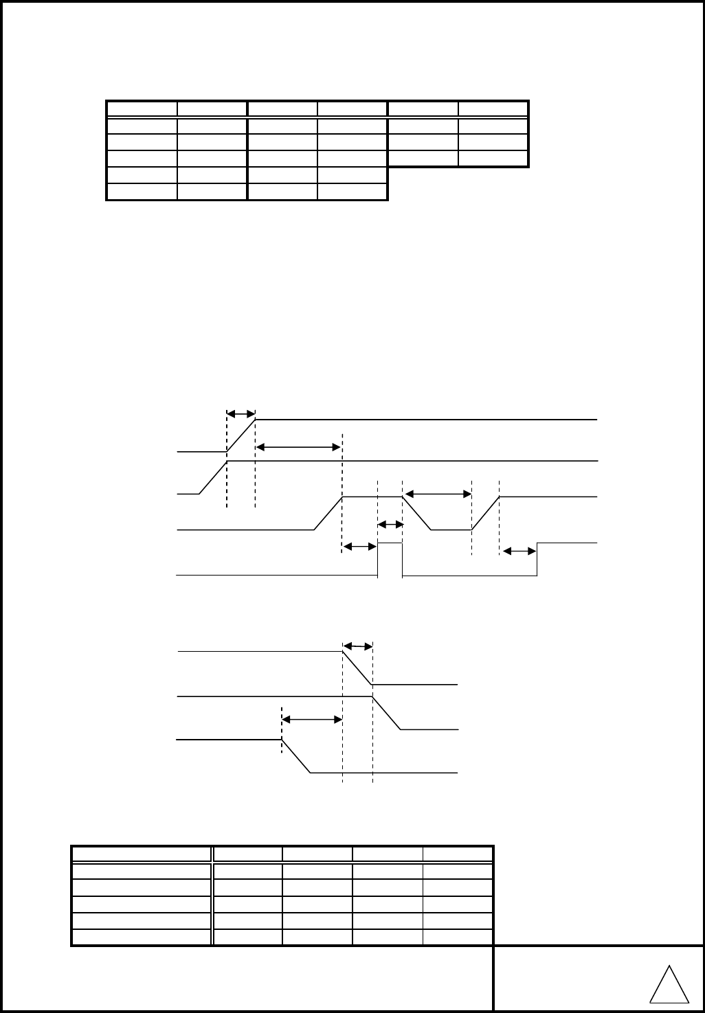
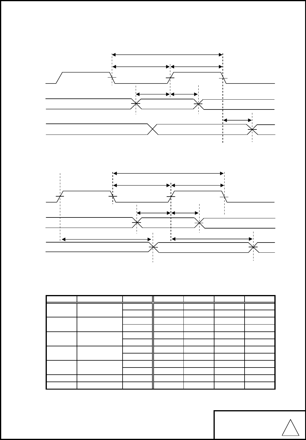
3-2. Power Sequence
電源仕様
3-2-1. Recommended power on timing 電源投入推奨タイミング
T0≧0ms T1 ≧ 750ms T2 ≧ 4ms T3 ≧ 0ms T4 ≧ 250ms
3-2-2. Recommended power off timing 電源切断推奨タイミング
T5 ≧ 0ms T6 ≧ 0ms
3-3. Interface specification (SDIO)
MITSUMI ELECTRIC CO.,LTD.
Parameter
CH ID Freq
5
3
4
1
2
V
-
0.4
Units
mV
0.3*VIO V
-
V
11
12
10
Min
6
9
Max
13
CH ID
-V
CH ID
7
8
VIO+0.3
Freq
Typ
Freq
Input high voltage 0.7*VIO
-
Input low voltage -0.3
-
Input hysteresis
DWG.NO.
0980
Output low voltage -
200
-
-
VIO-0.4
Output high voltage
VDD33
VIO
VDD33
VIO
Pdn
Pdn
T5
Host controll enable
T2 T2
T3
T1
T4
T0
T6
1
(
5
)
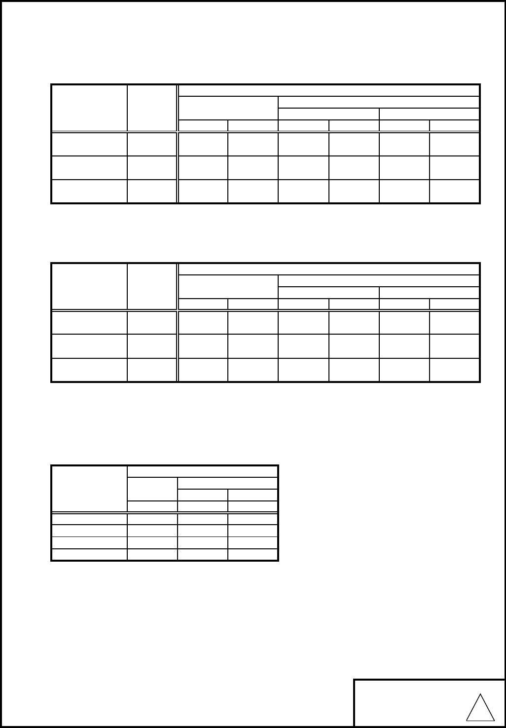
3-4. SDIO Protocol Timing
3-4-1 Normal Mode
3-4-2 High Speed Mode
3-4-3. SDIO Timing Data
MITSUMI ELECTRIC CO.,LTD.
Min Typ
Normal 0
fpp
Parameter
Clock Frequency
ModeSymol
High Speed 0
-
High Speed 7
-
Normal 10
-
High Speed
-
High Speed
7
Toh
Tih
Output Hold Time
Todly
Twl Clock Low Time
Input Hold Time
Output Delay Time
Input Setup Time
Twh
Tisu
Clock High Time
-High Speed
Units
25 MHz
50 MHz
Max
10
-
Normal
2-
5
Normal -
5
High Speed
Normal
6
-ns
-ns
DWG.NO.
0980
-
--
ns
7.33 ns
2.5
ns
-
ns
ns
-
-
-
-
-ns
-ns
--ns
-
fpp
Twl Twh
Tisu Tih
Todly
fpp
Twl Twh
Tisu Tih
Toh
Todly
1
(
6
)
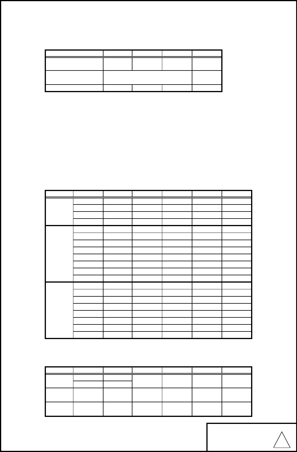
3-5. Current consumption
消費電流
TX mode
送信時消費電流
RX mode
受信時消費電流
Power Save Mode
MITSUMI ELECTRIC CO.,LTD.
Max. Typ. Max.
0.001
-
Current Consumption(mA)
VIO
Typ. Typ.
0.001
1.5000.33
1.8V
-
-220 260 0.0920.33 -
Standard Data rate VIO
3.3V 1.8V
VDD33
Current Consumption(mA)
Typ. Max.Typ.
3.3V
Max.Typ. Typ.
1.8V
Max.
1.600
--
Max.
VIO
0.070
0.33 0.051 -
220 260 0.33
-
0.33
0.33
0.391 --
-
220
Typ.
180
VDD33
140 180
180
260
Current Consumption(mA)
-
802.11b
@14dBm
802.11g
@12dBm
11Mbps
Standard Data rate
802.11n
@12dBm
54Mbps
HT20 MCS7
0.349
Deep sleep 0.400 0.603
Pdn 0.053
DWG.NO.
0980
0.183
0.001
54Mbps
VDD33
0.546
DTIM=3
4.103DTIM=1
0.5861.662
802.11g
802.11b
140
Typ.
140802.11n
Standard 3.3V
11Mbps
HT20 MCS7
1
(
7
)
3-6. Antenna specification (Referential specification)
アンテナ特性(参考特性)
DSC set installed
DSCセット組み込み時
※アンテナ共振周波数調整はDSCセット組み込みで行っております。
モジュール単体特性での保証ではございません。
疑義が生じた場合、DSCセット組み込みを行い確認を行う事とする。
Antenna resonant frequency is adjusted with DSC set installed.
This does not guarantee specification of the module alone.
In case of doubt, verification will be perfomed with DSC set installed.
3-7. Receiver characteristics
受信特性
1)Minimum Receiver Sensitivity
最小受信感度 (Ta=25℃)
1Mbps 8%
2Mbps 8%
5.5 Mbps 8%
11 Mbps 8%
6Mbps 10 %
9Mbps 10 %
12 Mbps 10 %
18 Mbps 10 %
24 Mbps 10 %
36 Mbps 10 %
48 Mbps 10 %
54 Mbps 10 %
10 %
10 %
10 %
10 %
10 %
10 %
10 %
10 %
2)Maximum Receiver Sensitivity
最大受信感度 (Ta=25℃)
MITSUMI ELECTRIC CO.,LTD.
3.0
MHz2412 - 2472
- 2.5
MAX Unit
Nominal 50
公称 50 Ω
MIN TYP
MIN.Data rate
-
Standard
Standard
F
requency
B
an
d
周波数帯域
Impedance
インピーダンス
VSWR
802.11n
HT20 MCS0~7 -20
802.11b
802.11g -20
1M,2M
5.5M,11M
6M~54M
PER
dBm
TYP.
dBm
dBm
-69
MAX. Unit
dBm
-67 dBm-64
-65
dBm
dBm
dBm
PER
8%
dBm 10%
dBm
dBm
10%
DWG.NO.
0980
MAX.
dBm
dBm
-79
dBm
dBm
Unit
dBm
dBm
-80
TYP.
-84
- -94
-
-88-
-
-91
MCS1 -
-
-
-
802.11b
-MCS0
802.11n
HT20
-
-
MCS7
-
MCS5
-
-MCS2
MCS3
MCS6
-MCS4 -75
- -71
Standard Data rate MIN.
802.11g
-
-
-
--
-4 -
-10
--
-
-87
-79
-73
-80
-76
-76
-82-87
-85
-71
-83
-77
-81
-83
-80
-79
-77
-74
-82
-79
-86
dBm
-70
-66 dBm
-65
dBm
dBm
-81
-66
dBm
dBm
-74
-70
1
(
8
)
3-8. Transmitter characteristics / 送信特性
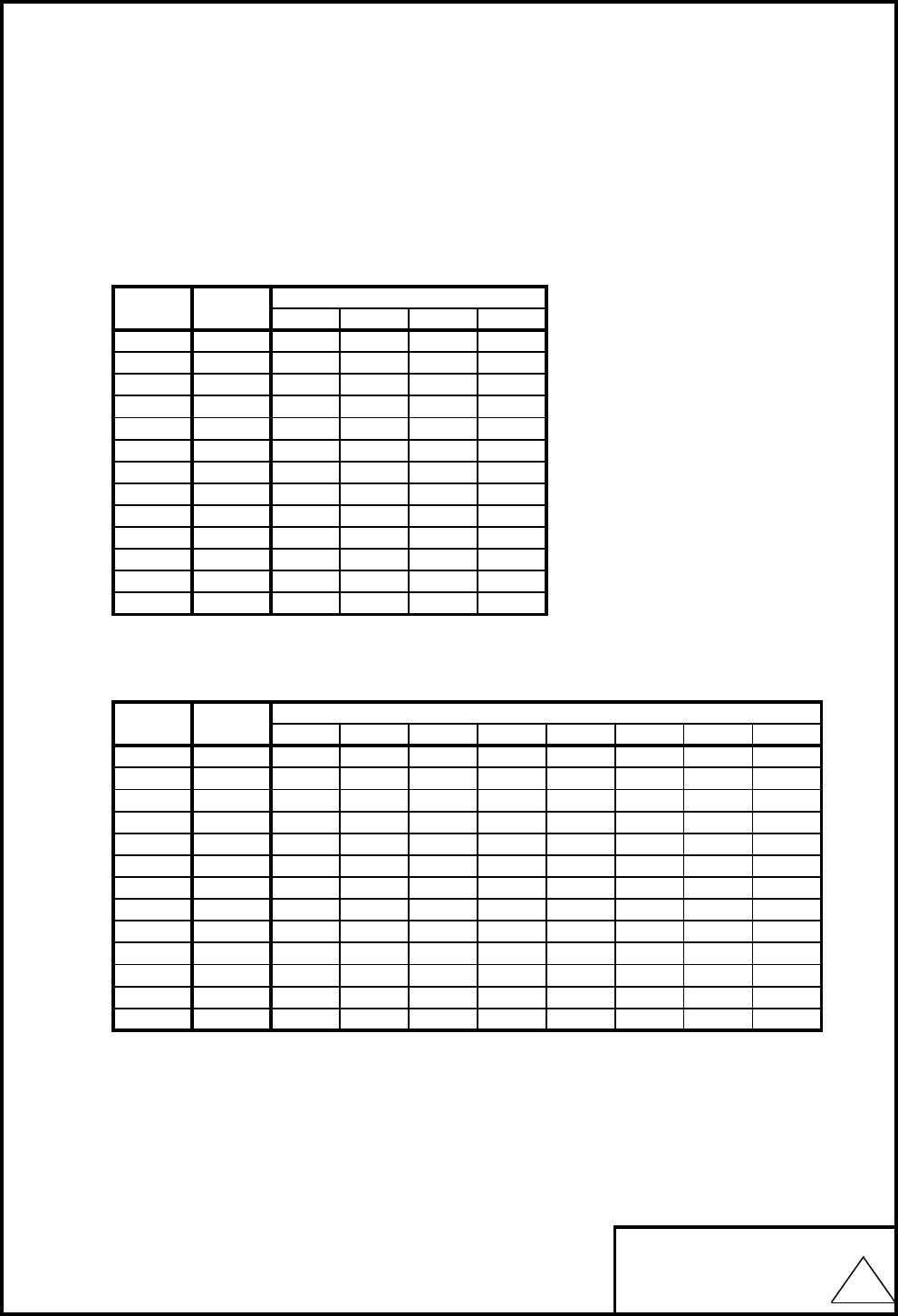
1)Output Target Power Levels
出力レベル
The difference of the output is within ±2.5dB. (Ta=25℃)
出力公差は、±2.5dB以内(Ta=25℃)の事
1) - 1 2.4GHz Band
11b (DSSS)
1M 2M 5.5M 11M
1 2412 14 14 14 14
2 2417 14 14 14 14
3 2422 14 14 14 14
4 2427 14 14 14 14
5 2432 14 14 14 14
6 2437 14 14 14 14
7 2442 14 14 14 14
8 2447 14 14 14 14
9 2452 14 14 14 14
10 2457 14 14 14 14
11 2462 14 14 14 14
12 2467 14 14 14 14
13 2472 14 14 14 14
1) - 2 2.4GHz Band
11g (OFDM)
Ch
6M 9M 12M 18M 24M 36M 48M 54M
1 2412 10 10 10 10 10 10 10 10
2 2417 12 12 12 12 12 12 12 12
3 2422 12 12 12 12 12 12 12 12
4 2427 12 12 12 12 12 12 12 12
5 2432 12 12 12 12 12 12 12 12
6 2437 12 12 12 12 12 12 12 12
7 2442 12 12 12 12 12 12 12 12
8 2447 12 12 12 12 12 12 12 12
9 2452 12 12 12 12 12 12 12 12
10 2457 12 12 12 12 12 12 12 12
11 2462 10 10 10 10 10 10 10 10
12 2467 12 12 12 12 12 12 12 12
13 2472 12 12 12 12 12 12 12 12
MITSUMI ELECTRIC CO.,LTD.
0980
DWG.NO.
Ch Freq.
(MHz)
Target Power (dBm)
Freq.
(MHz)
Target Power (dBm)
1
(
9
)
1) - 3 2.4GHz Band
11n/HT20 (OFDM)
MCS0 MCS1 MCS2 MCS3 MCS4 MCS5 MCS6 MCS7
1 2412 10 10 10 10 10 10 10 10
2 2417 12 12 12 12 12 12 12 12
3 2422 12 12 12 12 12 12 12 12
4 2427 12 12 12 12 12 12 12 12
5 2432 12 12 12 12 12 12 12 12
6 2437 12 12 12 12 12 12 12 12
7 2442 12 12 12 12 12 12 12 12
8 2447 12 12 12 12 12 12 12 12
9 2452 12 12 12 12 12 12 12 12
10 2457 12 12 12 12 12 12 12 12
11 2462 10 10 10 10 10 10 10 10
12 2467 12 12 12 12 12 12 12 12
13 2472 12 12 12 12 12 12 12 12
2)EVM
ITEM Max Unit
11b 1 Mbps -9 35.0 dB %
11b 2 Mbps -9 35.0 dB %
11b 5.5 Mbps -9 35.0 dB %
11b 11 Mbps -9 35.0 dB %
11g 6 Mbps -5 56.2 dB %
11g 9 Mbps -8 39.8 dB %
11g 12 Mbps -10 31.6 dB %
11g 18 Mbps -13 22.4 dB %
11g 24 Mbps -16 15.8 dB %
11g 36 Mbps -19 11.2 dB %
11g 48 Mbps -22 7.9 dB %
11g 54 Mbps -25 5.6 dB %
11n HT20 MCS0 -5 56.2 dB %
11n HT20 MCS1 -10 31.6 dB %
11n HT20 MCS2 -13 22.4 dB %
11n HT20 MCS3 -16 15.8 dB %
11n HT20 MCS4 -19 11.2 dB %
11n HT20 MCS5 -22 7.9 dB %
11n HT20 MCS6 -25 5.6 dB %
11n HT20 MCS7 -28 4.0 dB %
MITSUMI ELECTRIC CO.,LTD.
0980
DWG.NO.
Ch Freq.
(MHz)
Target Power (dBm)
1
(
10
)
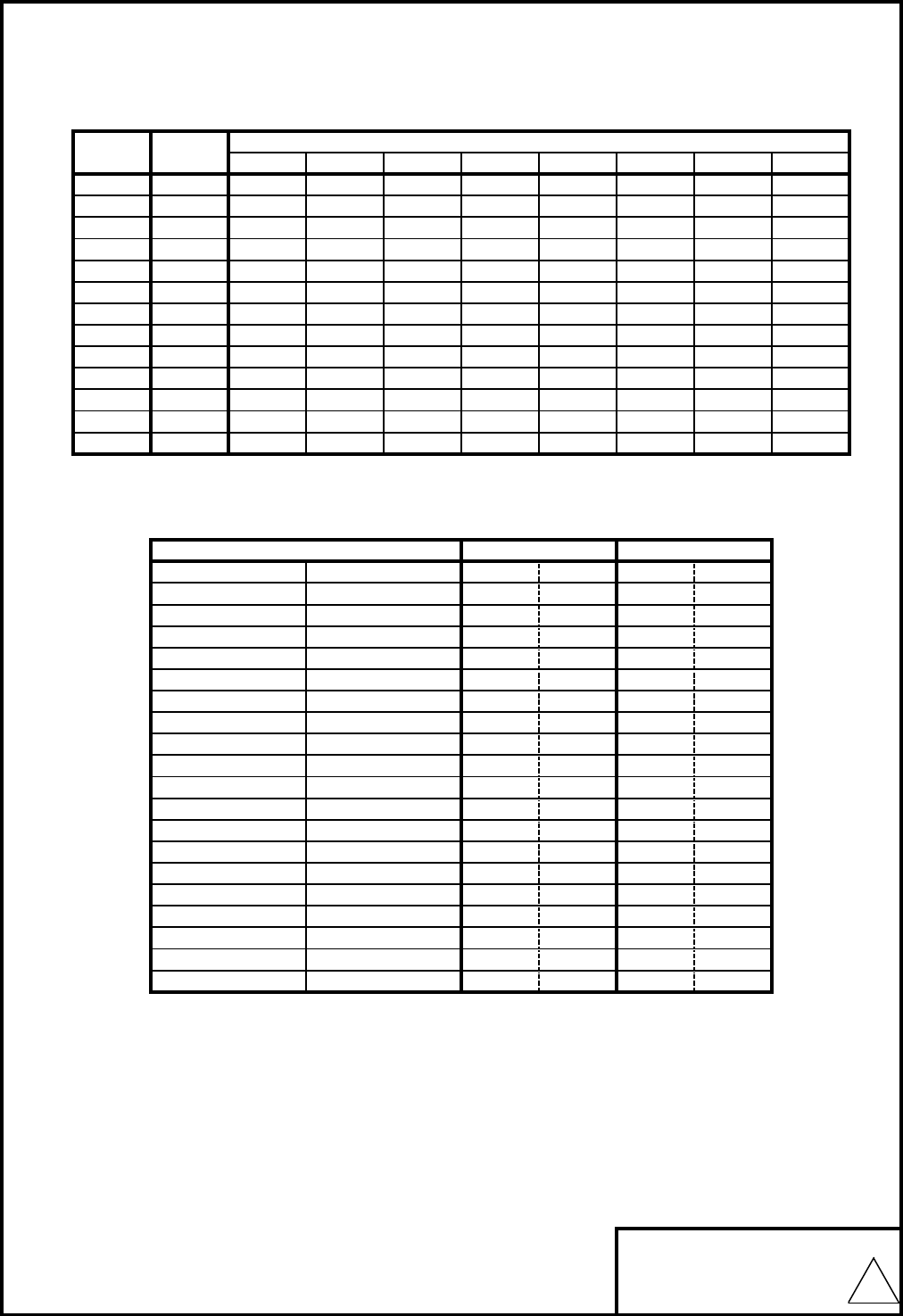
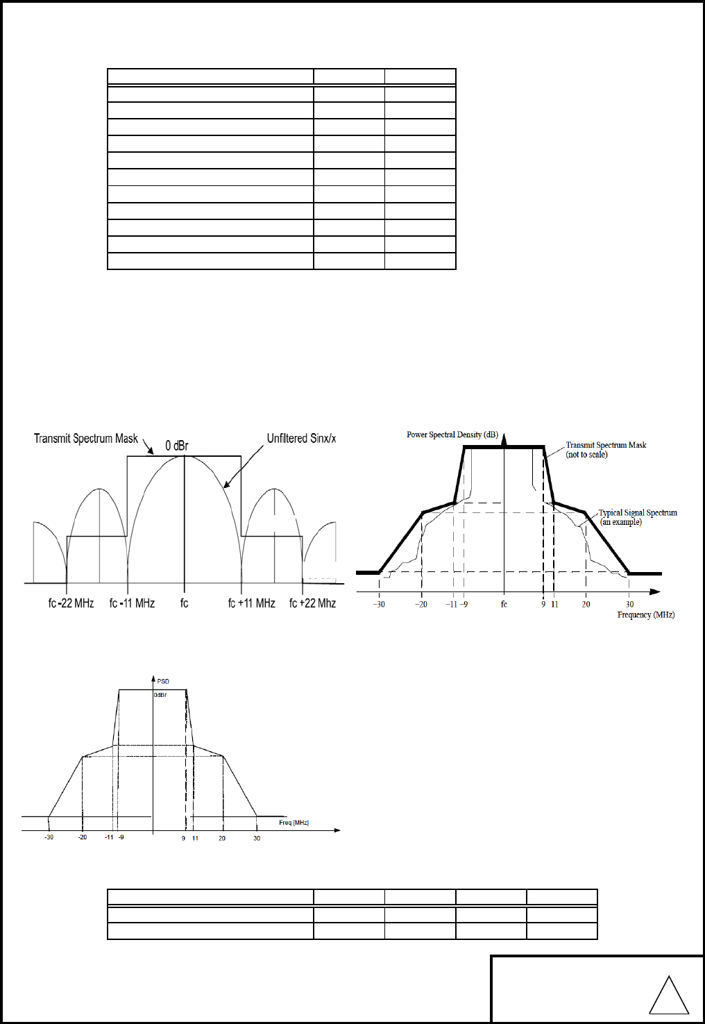
3)Spectrum Mask
ITEM Max Unit
DS 0MHz~±11MHz 0 dBr
DS -28 dBr
DS f±22MHz~ -50 dBr
OFDM 0MHz~±9MHz 0 dBr
OFDM f±11MHz -20 dBr
OFDM f±20MHz -28 dBr
OFDM f±30MHz -40 dBr
HT20 0MHz~±9MHz 0 dBr
HT20 f±11MHz -20 dBr
HT20 f±20MHz -28 dBr
HT20 f±30MHz -45 dBr
<DS> <OFDM>
<HT40>
<HT20>
4)Frequency Accuracy
周波数偏差
Condition Min Typ Max Unit
Ta = 25℃ -10 10 ppm
Ta =-20℃~70℃ -25 25 ppm
MITSUMI ELECTRIC CO.,LTD.
f±11MHz~±22MHz
0980
DWG.NO.
-
-
-50dBr
-28dBr
-20dBr
-28dBr
-40dBr
-45dBr
-20dBr
-28dBr
1
(
11
)
4.Measurement method
測定方法
Standard test shall be conducted under the following conditions. However, if no question arises as to
judgment, the test can be conducted in the range of temperature 20℃-30℃
and relative humidity 45%-70%.
Measurement needs to be performed in a shield room.
標準試験は、下記の条件で行うものとする。但し、判定に疑義を生じない場合は、温度20℃~30℃
相対湿度45%~70%の範囲にて試験してもよい。
測定は、シールドルーム内で行うこと。
Temperature 温度 : 25±3℃
Humidity 湿度 : 65±10%
Power supply voltage 3.3
V
:Refer to 2-3. 2-3を参照の事
電源電圧
4-1. TX test condition.
送信試験環境
SDIO/IF Coaxial
PC
-
--------------------------
-
DUT -------------
-
Spectrum
Analyzer
OR
Power
Meter
OR
WLAN
Tester
4-2. RX test condition
受信試験環境
SDIO/IF Coaxial Golden unit
PC --------
-
-
------------
-
DUT ATT ---- ---- PC
OR
Signal generator
OR
WLAN
Tester
MITSUMI ELECTRIC CO.,LTD.
RF Switch
Connector
RF Switch
Connector
0980
---------
DWG.NO.
1
(
12
)
5. Mechanical Specifications
機械的仕様
5-1. Dimension
寸法
9.0mm×19.5mm, t= 1.6mm MAX
5-2. Weight
重量
Typical 0.5g
5-3. Terminal number and name
端子・端子名
Connector model
コネクタ型名: 14FZ-SM1-GAN-TB JST
MITSUMI ELECTRIC CO.,LTD.
IO
SD_D0
1
No. Name
3
Pdn
SD_CMD
2VIO
IN
Function
I/F power supply
H/W reset
POWER
Type
0980
DWG.NO.
SDIO command
Main power supply 3.3V
9
GND GND
SDIO data 0
IO
GND
SDIO data 1
SD_CLK
4
SD_D2
IO SDIO data 3
IO
SD_D1 IO
GND GND
6
SDIO data 2
IO SDIO clock
GND GND
OUT Host wake up
POWER Main power supply 3.3V
POWER
14 Host WakeUp
13 VDD33
5
VDD33
7
10
GND
12
11
SD_D3
GND
8
1
(
13
)
6.Reliability Test
信頼性試験
N
O
1
2
3
4
5
6
7
8
10
11
Package vibration test conditions./梱包振動試験条件
DWG.NO.
MITSUMI ELECTRIC CO.,LTD.
0.048
-1.29
0980
Free drop three times on hard wooden board from 50 cm. Must operate
normally. Appearance: no functional damage.
木板に対して、50cm高さより自然落下。3回。JIS C 60068-2-32に従う。
動作上問題なき事。/外観:実使用上問題なき事。
Total five drops on bottom and sides of carton on hard wooden board from
50 cm. Must operate normally. Appearance: no functional damage.
木板に対して、50cm高さより自然落下。
梱包箱底面及び側面 計5回
Level[(ms^2)^2/Hz]
0.048
-
1.15
-
Slope[dB/oct]
High temperature
operation
高温動作
Operates properly after 500 hours at +70℃, followed by more than 2 hours at
ambient temperature/humidity.
+70℃で、500時間通電放置、その後常温常湿中に取り出し、2時間以上放置後
に、正常に動作する事。
±2.0kV applied to connector terminal and antenna terminal ±2.0kV、印
加箇所;コネクタ端子、アンテナ端子
High temperature
humidity storage
高温高湿放置
Operates properly after 1000 hours at +85℃, 85%RH followed by more than 2
hours at ambient temperature/humidity .
+85℃、85%RHにて1000時間放置、その後常温常湿中に取り出し、2時間以上
放置後に正常に動作する事。
High temperature
humidity operation
高温高湿動作
Operates properly after 1000 hours at +60℃, 90%RH followed by more
than 2 hours at ambient temperature/humidity .
+60℃、90%RHにて1000時間通電放置、その後常温常湿中に取り出
し、2時間以上放置後に正常に動作する事。
Thermal impact
test 熱衝撃試験
Operates properly after 100 cycles where one cycle is -30℃/30 min and
+85℃/30min.
-30℃/30分、+85℃/30分を1サイクルとして、100サイクル実施後、正常に動作す
る事。
Electrostatic
discharge
静電気放電
Item 項目 Test Conditions 試験
条
件
Low temperature
storage
低温放置
Operates properly after 1000 hours at -30℃, followed by more than 2 hours at
ambient temperature/humidity.
-30℃、1000時間放置、その後常温常湿中に取り出し、2時間以上放置後に、正
常に動作する事。
Test condition: No condensing
試験条件:露無き事。
High temperature
storage
高温放置
Operates properly after 1000 hours at +85℃, followed by more than 2 hours at
ambient temperature/humidity.
+85℃、1000時間放置、その後常温常湿中に取り出し、2時間以上放置後に、正
常に動作する事。
Low temperature
operation
低温動作
Operates properly after 500 hours at -20℃, followed by more than 2 hours at
ambient temperature/humidity .
-20℃で、500時間通電放置、その後常温常湿中に取り出し、2時間以上放置後
に、正常に動作する事。
P
ac
k
age v
ib
rat
i
on
test
梱包振動試験
Must operate normally after testing under conditions listed below.
欄外に示す条件にて試験を行い、試験後正常に動作する事.
9
Drop test
落下試験
Vibration test
振動試験
Must operate normally after vertical and two horizontal direction vibration for 2 hrs each at
frequency 10-50 Hz, amplitude 1.5 mm P-P.
振動周波数 10~50Hzにて、振幅1.5mmP-Pとし、上下:2h,左右:2h,前後:2hにて加振後、
正常に動作する事。
Frequency[Hz]
3
Test conditions/試験条件:
Non operating state/製品非動作状態
Discharged capacity /放電容量:100pF
Discharged resistance /放電抵抗:1.5kΩ
Application /印加回数:3回
Alone
単体落下
Packaged
梱包落下
0.096 -
-
-
-
+13.75
-
-9.34
Test Direction
Three directions
X,Y,Z
3方向
4 hours each
direction
各方向
4時間
Test Duration
40~200
200
3~6
6~18
18~40
40
1