Fuji Film 02000003 Wireless LAN Module User Manual FZ00010935 700 5x
Fuji Film Corporation Wireless LAN Module FZ00010935 700 5x
UserManual.wiki
>
Fuji Film
>
02000003 User Manual
Users Manual
Navigation menu
Upload a User Manual
Namespaces
Wiki Guide
HTML
PDF
Info
Views
User Manual
Discussion / Help
Navigation
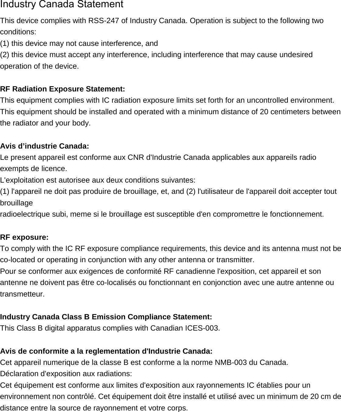

![2-3.Power supply Symbol Min.[V] TYP. Max.[V] VDD33 3.14 - 3.46 VIO 1.60 - 3.46 3.Electrical Characteristics 3-1.Channel Plan IEEE802.11b/g/n(HT20) CH ID Freq.[MHz] CH ID Freq.[MHz] CH ID Freq.[MHz] 1 2412 6 2437 11 2462 2 2417 7 2442 12 2467 3 2422 8 2447 13 2472 4 2427 9 2452 5 2432 10 2457 IEEE802.11n(HT40) CH ID Freq.[MHz] CH ID Freq.[MHz] 1 2422 6 2447 2 2427 7 2452 3 2432 4 2437 5 2442 3-2.Power Sequence Recommended power on timing VDD33 be ready before VIO and then enable PAD_EN for internal PMU blocks](https://usermanual.wiki/Fuji-Film/02000003/User-Guide-3151131-Page-10.png)
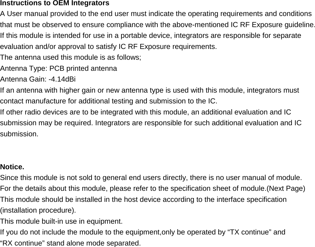
![3-3. Interface specification (SDIO) Parameter Min. [V] Typ. Max. [V] Input high voltage 0.625*VIO - VIO+0.3 Input low voltage -0.3 - 0.25*VIO Output high voltage 0.75*VIO - - Output low voltage - 0.125*VIO 3-4. SDIO Protocol Timing 3-4-1 Normal Mode 3-4-2 High Speed Mode](https://usermanual.wiki/Fuji-Film/02000003/User-Guide-3151131-Page-11.png)
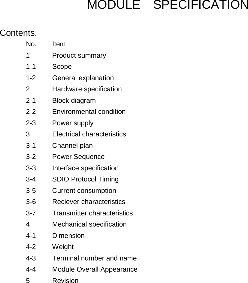
![3-4-3. SDIO Timing Data Symbol Parameter Mode Min Typ. Max fpp Clock Frequency Normal 0 [MHz] - 25 [MHz] High Speed 0 [MHz] - 50 [MHz] Twl Clock Low Time Normal 10 [ns] - High Speed 7 [ns] - Twh Clock High Time Normal 10 [ns] - High Speed 7 [ns] - Tisu Input Setup Time Normal 5 [ns] - High Speed 6 [ns] - Tih Input Hold Time Normal 5 [ns] - High Speed 2 [ns] - 14 [ns] Todly Output Delay Time Normal 0 [ns] - 14 [ns] High Speed - - 14 [ns] Toh Output Hold Time High Speed 2.5 [ns] - 3-5. Current consumption TX mode Standard Data rate VDD33 [mA] VIO [mA] Typ. Max. Typ. Max.802.11b 11Mbps 160 185 135 - 802.11g 54Mbps 115 135 135 - 802.11n HT20 MCS7 110 135 135 - 802.11n HT40 MCS7 97 120 135 - RX mode Standard Data rate VDD33 [mA] VIO [mA] Typ. Max. Typ. Max.802.11b 11Mbps 42 50 135 - 802.11g 54Mbps 42 50 135 - 802.11n HT20 MCS7 42 50 135 - 802.11n HT40 MCS7 42 50 135 -](https://usermanual.wiki/Fuji-Film/02000003/User-Guide-3151131-Page-12.png)
![3-6. Receiver characteristics 1) Minimum Receiver Sensitivity Standard Data rate Min.[dBm] Typ.[dBm] Max.[dBm] PER[%] 802.11b 1 Mbps - -95 -80 8 2 Mbps - -93 -80 8 5.5 bps - -89 -76 8 11 Mbps - -86 -76 8 802.11b 6 Mbps - -89 -82 10 9 Mbps - -88 -81 10 12 Mbps - -86 -79 10 18 Mbps - -84 -77 10 24 Mbps - -81 -74 10 36 Mbps - -80 -70 10 48 Mbps - -74 -66 10 54 Mbps - -72 -65 10 802.11n HT20 MCS0 - -88 -82 10 MCS1 - -85 -79 10 MCS2 - -83 -77 10 MCS3 - -81 -74 10 MCS4 - -77 -70 10 MCS5 - -73 -66 10 MCS6 - -71 -65 10 MCS7 - -69 -64 10 802.11n HT40 MCS0 - -87 -79 10 MCS1 - -84 -76 10 MCS2 - -82 -74 10 MCS3 - -80 -71 10 MCS4 - -76 -67 10 MCS5 - -72 -53 10 MCS6 - -69 -62 10 MCS7 - -67 -61 10 2)Maximum Receiver Sensitivity Standard Data rate Min.[dBm] Typ.[dBm] Max.[dBm] PER[%]802.11b 1M,2M -4 - - 8 5.5M,11M -10 - - 10 802.11g 6M to 54M -20 - - 10 802.11n HT20 MCS0 to 7 -20 - - 10 802.11n HT40 MCS0 to 7 -30 - - 10](https://usermanual.wiki/Fuji-Film/02000003/User-Guide-3151131-Page-13.png)
![3-7. Transmitter characteristics 1)Output Target Power Levels The difference of the output is within ±2.5dB. Output level, will be defined at the antenna feed point. 1)-1 2.4GHz Band 11b (DSSS) Ch Freq.[MHz] Target Power [dBm] 1M 2M 5.5M 11M 1 2412 13.5 13.5 13.5 13.5 2 2417 13.5 13.5 13.5 13.5 3 2422 13.5 13.5 13.5 13.5 4 2427 13.5 13.5 13.5 13.5 5 2432 13.5 13.5 13.5 13.5 6 2437 13.5 13.5 13.5 13.5 7 2442 13.5 13.5 13.5 13.5 8 2447 13.5 13.5 13.5 13.5 9 2452 13.5 13.5 13.5 13.5 10 2457 13.5 13.5 13.5 13.5 11 2462 13.5 13.5 13.5 13.5 12 2467 13.5 13.5 13.5 13.5 13 2472 13.5 13.5 13.5 13.5 11g (OFDM) Ch Freq.[MHz] Target Power [dBm] 6M 9M 12M 18M 24M 36M 48M 56M 1 2412 12 12 12 12 12 12 12 12 2 2417 12 12 12 12 12 12 12 12 3 2422 12 12 12 12 12 12 12 12 4 2427 12 12 12 12 12 12 12 12 5 2432 12 12 12 12 12 12 12 12 6 2437 12 12 12 12 12 12 12 12 7 2442 12 12 12 12 12 12 12 12 8 2447 12 12 12 12 12 12 12 12 9 2452 12 12 12 12 12 12 12 12 10 2457 12 12 12 12 12 12 12 12 11 2462 12 12 12 12 12 12 12 12 12 2467 12 12 12 12 12 12 12 12 13 2472 12 12 12 12 12 12 12 12](https://usermanual.wiki/Fuji-Film/02000003/User-Guide-3151131-Page-14.png)
![11n /HT20(OFDM) 11n /HT20(OFDM) Ch (HT20) Ch (HT40) Freq. [MHz] Target Power [dBm] MCS0 MCS1 MCS2 MCS3 MCS4 MCS5 MCS6 MCS71 - 2412 12 12 12 12 12 12 12 12 2 - 2417 12 12 12 12 12 12 12 12 3 1 2422 12 12 12 12 12 12 12 12 4 2 2427 12 12 12 12 12 12 12 12 5 3 2432 12 12 12 12 12 12 12 12 6 4 2437 12 12 12 12 12 12 12 12 7 5 2442 12 12 12 12 12 12 12 12 8 6 2447 12 12 12 12 12 12 12 12 9 7 2452 12 12 12 12 12 12 12 12 10 - 2457 12 12 12 12 12 12 12 12 11 - 2462 12 12 12 12 12 12 12 12 12 - 2467 12 12 12 12 12 12 12 12 13 - 2472 12 12 12 12 12 12 12 12 2)EVM ITEM rate EVM [%] 11b 1 Mbps 35 11b 2 Mbps 35 11b 5.5 Mbps 35 11b 11 Mbps 35 11b 6 Mbps 56.2 11g 9 Mbps 39.8 11g 12 Mbps 31.6 11g 18 Mbps 22.4 11g 24 Mbps 15.8 11g 36 Mbps 11.2 11g 48 Mbps 7.9 11g 54 mBps 5.6 11n HT20/HT40 MCS0 56.2 11n HT20/HT40 MCS1 31.6 11n HT20/HT40 MCS2 22.4 11n HT20/HT40 MCS3 15.8 11n HT20/HT40 MCS4 11.2 11n HT20/HT40 MCS5 7.9 11n HT20/HT40 MCS6 5.6 11n HT20/HT40 MCS7 4.0](https://usermanual.wiki/Fuji-Film/02000003/User-Guide-3151131-Page-15.png)
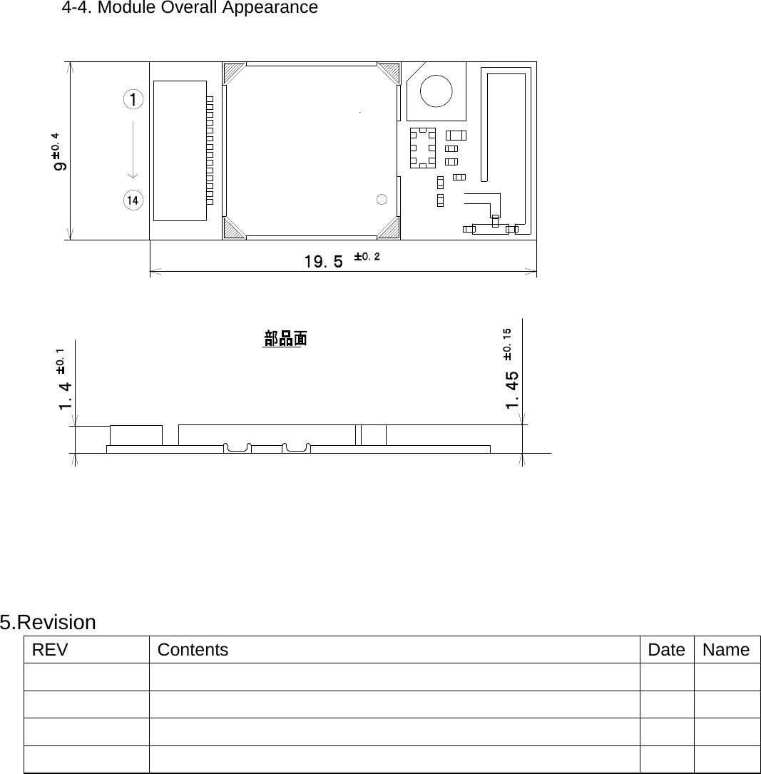
![3)Spectrum Mask Mask [dBr] DS 0MHz to +/-11MHz 0 DS f+/-11MHz to 22MHz -28 DS f+/-22MHz -50 OFDM 0MHz to +/-9MHz 0 OFDM f+/-11MHz -20 OFDM f+/-20MHz -28 OFDM f+/-30MHz -40 HT20 0MHz to +/-9MHz 0 HT20 f+/-11MHz -20 HT20 f+/-20MHz -28 HT20 f+/-30MHz -45 HT40 0MHz to +/-9MHz 0 HT40 f+/-11MHz -20 HT40 f+/-20MHz -28 HT40 f+/-30MHz -45 4)Frequency Accuracy +/- 20 ppm 4.Mechanical Specifications 4-1. Dimension : 9.0mm×19.5mm, t= 1.6mm MAX 4-2. Weight : Typical 0.5g 4-3. Terminal number and name No. Name Type Function 1 Pdn IN Power on reset 2 VIO POWER I/F power supply 3 SD_CMD IO SDIO command 4 SD_D0 IO SDIO data 0 5 SD_D1 IO SDIO data 1 6 GND GND GND 7 SD_CLK IO SDIO clock 8 GND GND GND 9 SD_D3 IO SDIO data 3 10 SD_D2 IO SDIO data 2 11 GND GND GND 12 VDD33 POWER Main power supply 3.3V 13 VDD33 POWER Main power supply 3.3V 14 HostWakeup OUT Host Wake up](https://usermanual.wiki/Fuji-Film/02000003/User-Guide-3151131-Page-16.png)