Fuji Film 02000003 Wireless LAN Module User Manual FZ00010935 700 5x
Fuji Film Corporation Wireless LAN Module FZ00010935 700 5x
Users Manual
User Manual
WIRELESS LAN MODULE
MODEL FZ00010935-700
The purpose of this manual is to explain correct way how to integrate module FZ00010935-700 to
the end product. It includes procedures that shall assist you to avoid unforeseen problems.
This manual presents information that shows how module and OEM product, where module
integrated,complies with regulations in certain regions. Any modifications, not expressly approved
by the manufacturer could void the authority to operate in these regions.
The wireless LAN module, model FZ00010935-700 has to be installed and used in accordance with
the technical description/installation instructions provided by the manufacturer.
For detail information concerning type approval of this module (e.g. where this module is already
pre-approved) please contact the authorized local distributor or the manufacturer.
The system may only be implemented in the configuration that was authorized.
Note that any changes or modifications to this equipment not expressly approved by the
manufacturer could void the user’s authority to operate this equipment.
Regulatory Information
Operational Information
Wireless Interoperability
The end product integrating this module is designed to be interoperable with any wireless LAN
product that is based on direct sequence spread spectrum (DSSS) and orthogonal frequency
division multiplexing (OFDM) radio technology and to comply with the following standards.
・IEEE Std 802.11b Standard on 2.4GHz Wireless LAN
・IEEE Std 802.11g Standard on 2.4GHz Wireless LAN
・IEEE Std 802.11n Standard on 2.4GHz Wireless LAN
Federal Communications Commission (FCC) Statement
15.105(b) This equipment has been tested and found to comply with the limits for a Class B digital
device, pursuant to part 15 of the FCC rules. These limits are designed to provide reasonable
protection against harmful interference in a residential installation. This equipment generates, uses
and can radiate radio frequency energy and, if not installed and used in accordance with the
instructions, may cause harmful interference to radio communications. However, there is no
guarantee that interference will not occur in a particular installation. If this equipment does cause
harmful interference to radio or television reception, which can be determined by turning the
equipment off and on, the user is encouraged to try to correct the interference by one or more of the
following measures:
-Reorient or relocate the receiving antenna.
-Increase the separation between the equipment and receiver.
-Connect the equipment into an outlet on a circuit different from that to which the receiver is
connected.
-Consult the dealer or an experienced radio/TV technician for help.
15.21: You are cautioned that changes or modifications not expressly approved by the part
responsible for compliance could void the user’s authority to operate the equipment.
FCC RF Radiation Exposure Statement:
1.This Transmitter must not be co-located or operating in conjunction with any other antenna or
transmitter.
2.This equipment complies with FCC RF radiation exposure limits set forth for an uncontrolled
environment. This equipment should be installed and operated with a minimum distance of 20
centimeters between the radiator and your body.
FCC RF Exposure requirements:
This device and its antenna(s) must not be co-located or operation in conjunction with any other
antenna or transmitter.
15.19
This device complies with Part 15 of the FCC Rules. Operation is subject to the following two
conditions:
1) this device may not cause harmful interference and
2) this device must accept any interference received, including interference that may cause undesired
operation of the device.
Labeling:
Wireless LAN module FZ00010935-700 labeled as below.
FCC ID: W2Z-02000003
The proposed with FCC ID label format is to be placed on the module. If FCC ID is not visible when
the module is installed into the system, “Contains FCC ID:
W2Z-02000003” shall be placed on the outside of final host system
Instructions to OEM Integrators
A User manual provided to the end user must indicate the operating requirements and conditions
that must be observed to ensure compliance with the above-mentioned FCC RF Exposure
guideline.
If this module is intended for use in a portable device, integrators are responsible for separate
evaluation and/or approval to satisfy FCC RF Exposure requirements.
The antenna used this module is as follows;
Antenna Type: PCB printed antenna
Antenna Gain: -4.14dBi
If an antenna with higher gain or new antenna type is used with this module, integrators must
contact to manufacture for additional testing and submission to the FCC.
If other radio devices are to be integrated with this module, an additional evaluation and FCC
submission may be required. Integrators are responsible for such additional evaluation and FCC
submission.
Industry Canada Statement
This device complies with RSS-247 of Industry Canada. Operation is subject to the following two
conditions:
(1) this device may not cause interference, and
(2) this device must accept any interference, including interference that may cause undesired
operation of the device.
RF Radiation Exposure Statement:
This equipment complies with IC radiation exposure limits set forth for an uncontrolled environment.
This equipment should be installed and operated with a minimum distance of 20 centimeters between
the radiator and your body.
Avis d’industrie Canada:
Le present appareil est conforme aux CNR d'Industrie Canada applicables aux appareils radio
exempts de licence.
L'exploitation est autorisee aux deux conditions suivantes:
(1) l'appareil ne doit pas produire de brouillage, et, and (2) l'utilisateur de l'appareil doit accepter tout
brouillage
radioelectrique subi, meme si le brouillage est susceptible d'en compromettre le fonctionnement.
RF exposure:
To comply with the IC RF exposure compliance requirements, this device and its antenna must not be
co-located or operating in conjunction with any other antenna or transmitter.
Pour se conformer aux exigences de conformité RF canadienne l'exposition, cet appareil et son
antenne ne doivent pas être co-localisés ou fonctionnant en conjonction avec une autre antenne ou
transmetteur.
Industry Canada Class B Emission Compliance Statement:
This Class B digital apparatus complies with Canadian ICES-003.
Avis de conformite a la reglementation d'Industrie Canada:
Cet appareil numerique de la classe B est conforme a la norme NMB-003 du Canada.
Déclaration d'exposition aux radiations:
Cet équipement est conforme aux limites d'exposition aux rayonnements IC établies pour un
environnement non contrôlé. Cet équipement doit être installé et utilisé avec un minimum de 20 cm de
distance entre la source de rayonnement et votre corps.
Labeling:
Wireless LAN module FZ00010935-700 labeled as below.
IC: 7736B-02000003
The proposed with IC ID label format is to be placed on the module. If IC ID is not visible when the
module is installed in to the system, “Contains IC: 7736B-02000003” shall be placed on the outside
of final host system.
Instructions to OEM Integrators
A User manual provided to the end user must indicate the operating requirements and conditions
that must be observed to ensure compliance with the above-mentioned IC RF Exposure guideline.
If this module is intended for use in a portable device, integrators are responsible for separate
evaluation and/or approval to satisfy IC RF Exposure requirements.
The antenna used this module is as follows;
Antenna Type: PCB printed antenna
Antenna Gain: -4.14dBi
If an antenna with higher gain or new antenna type is used with this module, integrators must
contact manufacture for additional testing and submission to the IC.
If other radio devices are to be integrated with this module, an additional evaluation and IC
submission may be required. Integrators are responsible for such additional evaluation and IC
submission.
Notice.
Since this module is not sold to general end users directly, there is no user manual of module.
For the details about this module, please refer to the specification sheet of module.(Next Page)
This module should be installed in the host device according to the interface specification
(installation procedure).
This module built-in use in equipment.
If you do not include the module to the equipment,only be operated by “TX continue” and
“RX continue” stand alone mode separated.
MODULE SPECIFICATION
Contents.
No. Item
1 Product summary
1-1 Scope
1-2 General explanation
2 Hardware specification
2-1 Block diagram
2-2 Environmental condition
2-3 Power supply
3 Electrical characteristics
3-1 Channel plan
3-2 Power Sequence
3-3 Interface specification
3-4 SDIO Protocol Timing
3-5 Current consumption
3-6 Reciever characteristics
3-7 Transmitter characteristics
4 Mechanical specification
4-1 Dimension
4-2 Weight
4-3 Terminal number and name
4-4 Module Overall Appearance
5 Revision
1.Product Summary
1-1.Scope
2.4 GHz WLAN module with integrated antenna
(IEEE 802.11 b/g/n supported)
1-2.General explanation
Standard IEEE802.11b/g/n
Frequency 2.4-2.4835GHz
Host Interfase SDIO ver2.0
Frequency Bandwidth 20MHz,40MHz
Weight 0.5g typ
・
Chipset:MediaTek Inc.RT6370(WLCSP Package)
・
Modulation Types: DBPSK, DQPSK and CCK with 802.11b mode
OFDM(BPSK, QPSK, 16-QAM and 64-QAM) with 802.11g/n mode
・
Data rate: 1,2,5.5 and 11 with 802.11b mode
6,9,12,18,24,36,48 and 54 with 802.11g mode
MCS0-7 with 802.11n mode
・
Security: WEP(64 and 128bits), WPA-PSK(TKIP/AES) and WPA2-PSK(TKIP/AES)
2.Hardware Specification
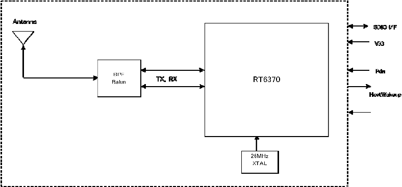
2-1. Block diagram
2-2.Environmental condition
1) Operating environment
Operating temperature range :
-20
~
85
℃ ※Temperature on the bottom of the module
Operating humidity range: 20%
~
80% (None dew)
2) Storage environment
Storage temperature range: -30
~
85
℃
Storage humidity range 20%
~
85%
(None dew)
2-3.Power supply
Symbol Min.[V] TYP
.
Max.[V]
VDD33 3.14 - 3.46
VIO 1.60 - 3.46
3.Electrical Characteristics
3-1.Channel Plan
IEEE802.11b/g/n(HT20)
CH ID Freq.[MHz] CH ID Freq.[MHz] CH ID Freq.[MHz]
1 2412 6 2437 11 2462
2 2417 7 2442 12 2467
3 2422 8 2447 13 2472
4 2427 9 2452
5 2432 10 2457
IEEE802.11n(HT40)
CH ID Freq.[MHz] CH ID Freq.[MHz]
1 2422 6 2447
2 2427 7 2452
3 2432
4 2437
5 2442
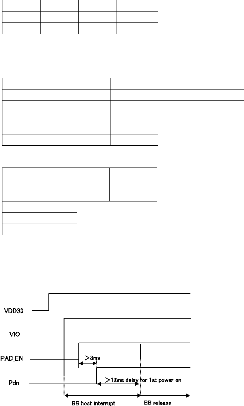
3-2.Power Sequence
Recommended power on timing
VDD33 be ready before VIO and then enable PAD_EN for internal PMU blocks
3-3. Interface specification (SDIO)
Parameter Min. [V] Typ. Max. [V]
Input high voltage 0.625*VIO - VIO+0.3
Input low voltage -0.3 - 0.25*VIO
Output high voltage 0.75*VIO - -
Output low voltage - 0.125*VIO
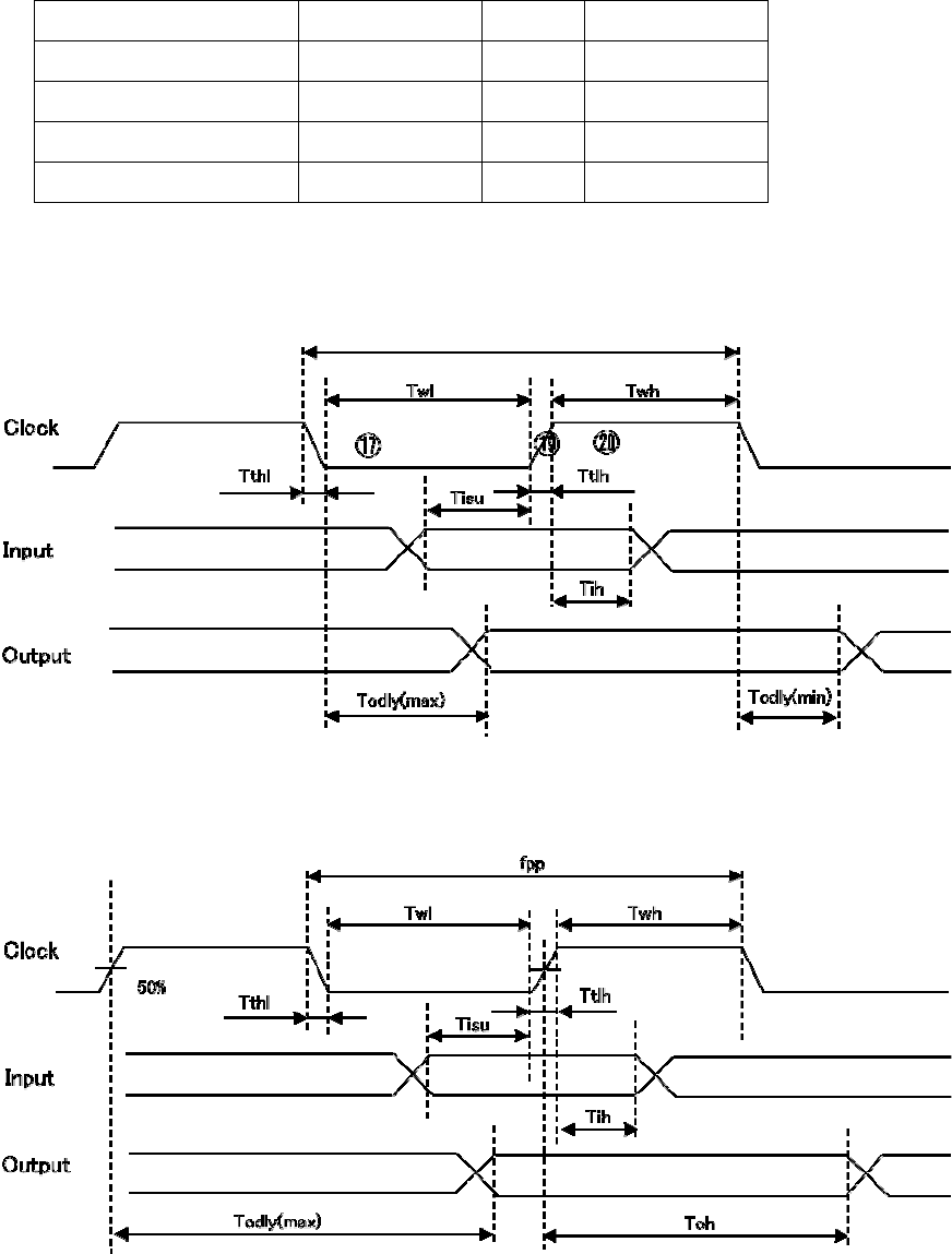
3-4. SDIO Protocol Timing
3-4-1 Normal Mode
3-4-2 High Speed Mode
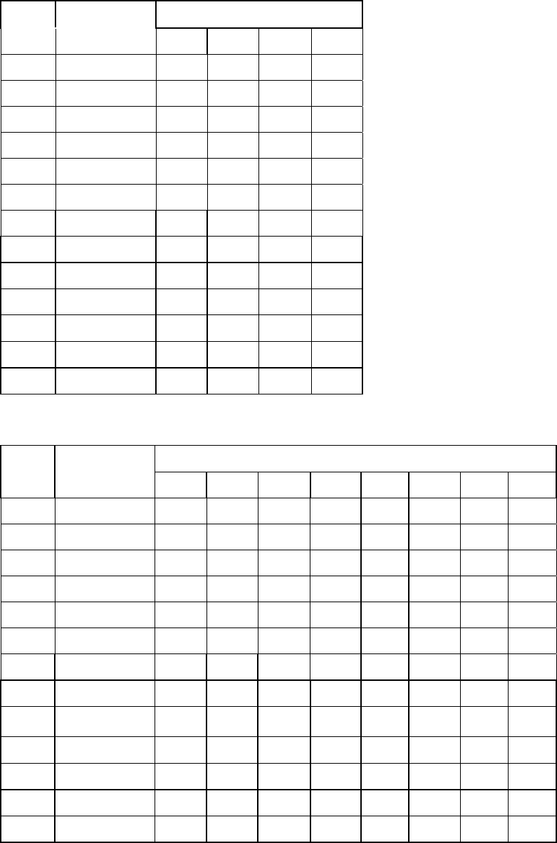
3-4-3. SDIO Timing Data
Symbol Parameter Mode Min Typ. Max
fpp Clock Frequency Normal 0 [MHz] - 25 [MHz]
High Speed 0 [MHz] - 50 [MHz]
Twl Clock Low Time Normal 10 [ns] -
High Speed 7 [ns] -
Twh Clock High Time Normal 10 [ns] -
High Speed 7 [ns] -
Tisu Input Setup Time Normal 5 [ns] -
High Speed 6 [ns] -
Tih Input Hold Time Normal 5 [ns] -
High Speed 2 [ns] - 14 [ns]
Todly Output Delay Time Normal 0 [ns] - 14 [ns]
High Speed - - 14 [ns]
Toh Output Hold Time High Speed 2.5 [ns] -
3-5. Current consumption
TX mode
Standard Data rate VDD33 [mA] VIO [mA]
Typ. Max. Typ. Max.
802.11b 11Mbps 160 185 135 -
802.11g 54Mbps 115 135 135 -
802.11n HT20 MCS7 110 135 135 -
802.11n HT40 MCS7 97 120 135 -
RX mode
Standard Data rate VDD33 [mA] VIO [mA]
Typ. Max. Typ. Max.
802.11b 11Mbps 42 50 135 -
802.11g 54Mbps 42 50 135 -
802.11n HT20 MCS7 42 50 135 -
802.11n HT40 MCS7 42 50 135 -

3-6. Receiver characteristics
1) Minimum Receiver Sensitivity
Standard Data rate Min.[dBm] Typ.[dBm] Max.[dBm] PER[%]
802.11b 1 Mbps - -95 -80 8
2 Mbps - -93 -80 8
5.5 bps - -89 -76 8
11 Mbps - -86 -76 8
802.11b 6 Mbps - -89 -82 10
9 Mbps - -88 -81 10
12 Mbps - -86 -79 10
18 Mbps - -84 -77 10
24 Mbps - -81 -74 10
36 Mbps - -80 -70 10
48 Mbps - -74 -66 10
54 Mbps - -72 -65 10
802.11n
HT20
MCS0 - -88 -82 10
MCS1 - -85 -79 10
MCS2 - -83 -77 10
MCS3 - -81 -74 10
MCS4 - -77 -70 10
MCS5 - -73 -66 10
MCS6 - -71 -65 10
MCS7 - -69 -64 10
802.11n
HT40
MCS0 - -87 -79 10
MCS1 - -84 -76 10
MCS2 - -82 -74 10
MCS3 - -80 -71 10
MCS4 - -76 -67 10
MCS5 - -72 -53 10
MCS6 - -69 -62 10
MCS7 - -67 -61 10
2)Maximum Receiver Sensitivity
Standard Data rate Min.[dBm] Typ.[dBm] Max.[dBm] PER[%]
802.11b 1M,2M -4 - - 8
5.5M,11M -10 - - 10
802.11g 6M to 54M -20 - - 10
802.11n HT20 MCS0 to 7 -20 - - 10
802.11n HT40 MCS0 to 7 -30 - - 10
3-7. Transmitter characteristics
1)Output Target Power Levels
The difference of the output is within ±2.5dB.
Output level, will be defined at the antenna feed point.
1)-1 2.4GHz Band
11b (DSSS)
Ch Freq.[MHz] Target Power [dBm]
1M 2M 5.5M 11M
1 2412 13.5 13.5 13.5 13.5
2 2417 13.5 13.5 13.5 13.5
3 2422 13.5 13.5 13.5 13.5
4 2427 13.5 13.5 13.5 13.5
5 2432 13.5 13.5 13.5 13.5
6 2437 13.5 13.5 13.5 13.5
7 2442 13.5 13.5 13.5 13.5
8 2447 13.5 13.5 13.5 13.5
9 2452 13.5 13.5 13.5 13.5
10 2457 13.5 13.5 13.5 13.5
11 2462 13.5 13.5 13.5 13.5
12 2467 13.5 13.5 13.5 13.5
13 2472 13.5 13.5 13.5 13.5
11g (OFDM)
Ch Freq.[MHz] Target Power [dBm]
6M 9M 12M 18M 24M 36M 48M 56M
1 2412 12 12 12 12 12 12 12 12
2 2417 12 12 12 12 12 12 12 12
3 2422 12 12 12 12 12 12 12 12
4 2427 12 12 12 12 12 12 12 12
5 2432 12 12 12 12 12 12 12 12
6 2437 12 12 12 12 12 12 12 12
7 2442 12 12 12 12 12 12 12 12
8 2447 12 12 12 12 12 12 12 12
9 2452 12 12 12 12 12 12 12 12
10 2457 12 12 12 12 12 12 12 12
11 2462 12 12 12 12 12 12 12 12
12 2467 12 12 12 12 12 12 12 12
13 2472 12 12 12 12 12 12 12 12
11n /HT20(OFDM)
11n /HT20(OFDM)
Ch
(HT20)
Ch
(HT40)
Freq.
[MHz]
Target Power [dBm]
MCS0 MCS1 MCS2 MCS3 MCS4 MCS5 MCS6 MCS7
1 - 2412 12 12 12 12 12 12 12 12
2 - 2417 12 12 12 12 12 12 12 12
3 1 2422 12 12 12 12 12 12 12 12
4 2 2427 12 12 12 12 12 12 12 12
5 3 2432 12 12 12 12 12 12 12 12
6 4 2437 12 12 12 12 12 12 12 12
7 5 2442 12 12 12 12 12 12 12 12
8 6 2447 12 12 12 12 12 12 12 12
9 7 2452 12 12 12 12 12 12 12 12
10 - 2457 12 12 12 12 12 12 12 12
11 - 2462 12 12 12 12 12 12 12 12
12 - 2467 12 12 12 12 12 12 12 12
13 - 2472 12 12 12 12 12 12 12 12
2)EVM
ITEM rate EVM [%]
11b 1 Mbps 35
11b 2 Mbps 35
11b 5.5 Mbps 35
11b 11 Mbps 35
11b 6 Mbps 56.2
11g 9 Mbps 39.8
11g 12 Mbps 31.6
11g 18 Mbps 22.4
11g 24 Mbps 15.8
11g 36 Mbps 11.2
11g 48 Mbps 7.9
11g 54 mBps 5.6
11n HT20/HT40 MCS0 56.2
11n HT20/HT40 MCS1 31.6
11n HT20/HT40 MCS2 22.4
11n HT20/HT40 MCS3 15.8
11n HT20/HT40 MCS4 11.2
11n HT20/HT40 MCS5 7.9
11n HT20/HT40 MCS6 5.6
11n HT20/HT40 MCS7 4.0

3)Spectrum Mask
Mask [dBr]
DS 0MHz to +/-11MHz 0
DS f+/-11MHz to 22MHz -28
DS f+/-22MHz -50
OFDM 0MHz to +/-9MHz 0
OFDM f+/-11MHz -20
OFDM f+/-20MHz -28
OFDM f+/-30MHz -40
HT20 0MHz to +/-9MHz 0
HT20 f+/-11MHz -20
HT20 f+/-20MHz -28
HT20 f+/-30MHz -45
HT40 0MHz to +/-9MHz 0
HT40 f+/-11MHz -20
HT40 f+/-20MHz -28
HT40 f+/-30MHz -45
4)Frequency Accuracy
+/- 20 ppm
4.Mechanical Specifications
4-1. Dimension : 9.0mm×19.5mm, t= 1.6mm MAX
4-2. Weight : Typical 0.5g
4-3. Terminal number and name
No. Name Type Function
1 Pdn IN Power on reset
2 VIO POWER I/F power supply
3 SD_CMD IO SDIO command
4 SD_D0 IO SDIO data 0
5 SD_D1 IO SDIO data 1
6 GND GND GND
7 SD_CLK IO SDIO clock
8 GND GND GND
9 SD_D3 IO SDIO data 3
10 SD_D2 IO SDIO data 2
11 GND GND GND
12 VDD33 POWER Main power supply 3.3V
13 VDD33 POWER Main power supply 3.3V
14 HostWakeup OUT Host Wake up
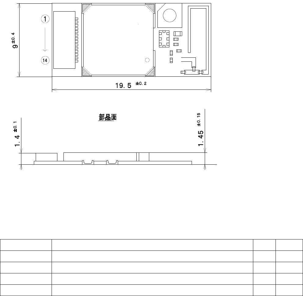
4-4. Module Overall Appearance
5.Revision
REV Contents Date Name