Fujian Newland Auto ID Tech NLS-HR52 Hand-held Barcode Scanner User Manual
Fujian Newland Auto-ID Tech Co., Ltd. Hand-held Barcode Scanner
UserManual.wiki
>
Fujian Newland Auto ID Tech
>
NLS HR52 User Manual
User manual
Navigation menu
Upload a User Manual
Namespaces
Wiki Guide
HTML
PDF
Info
Views
User Manual
Discussion / Help
Navigation
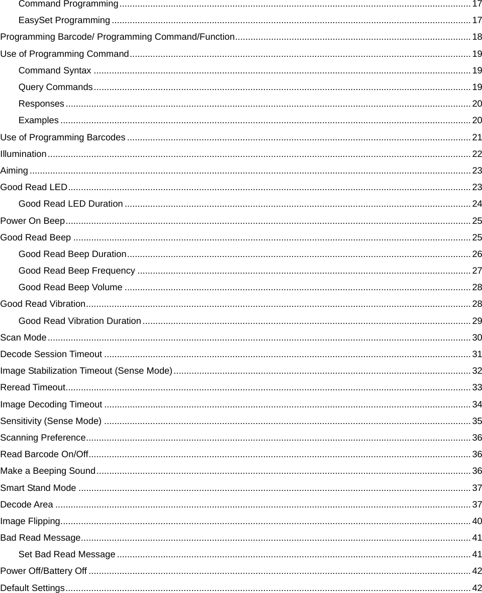
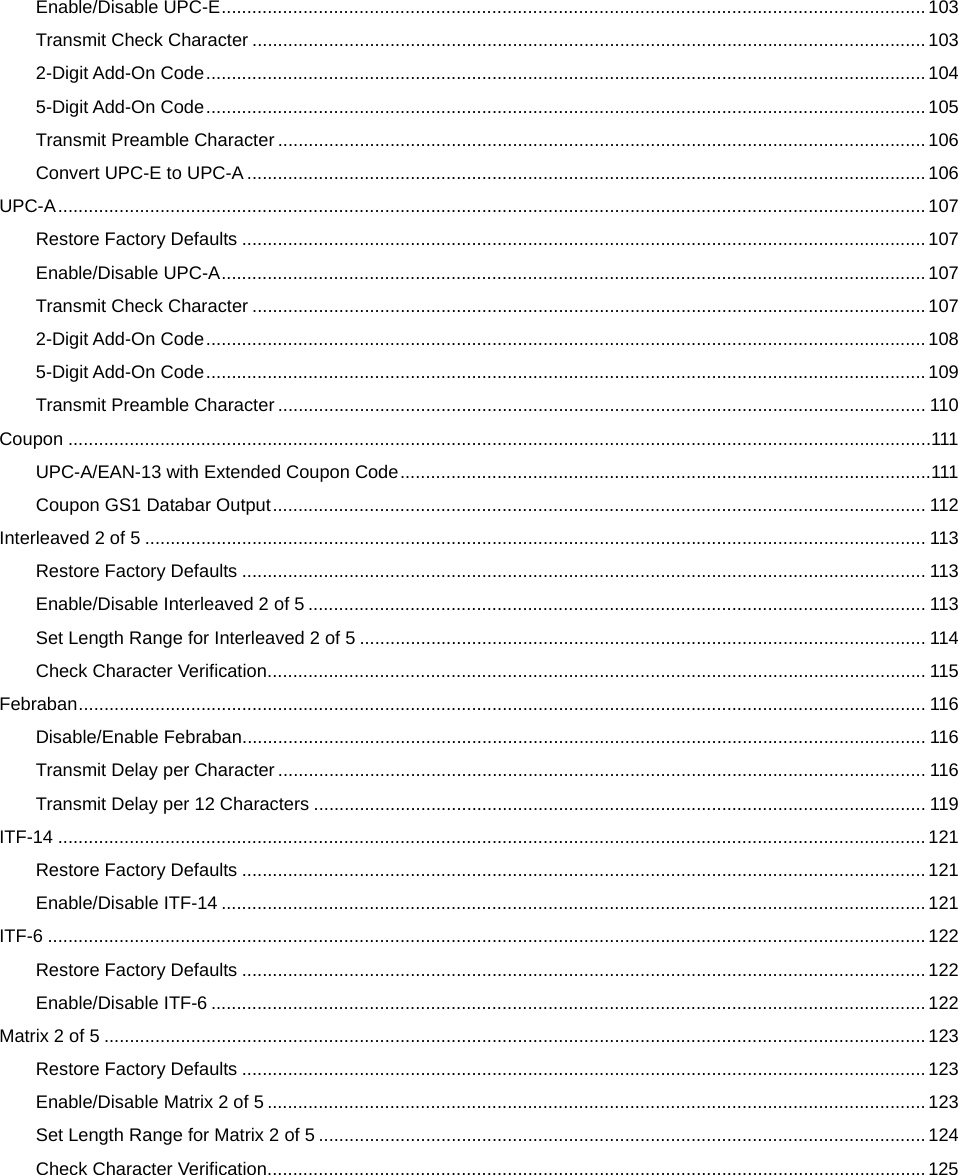
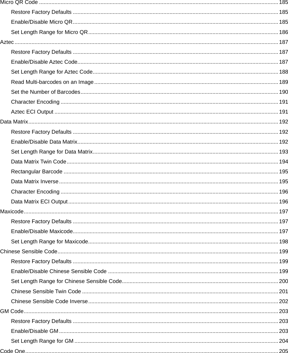
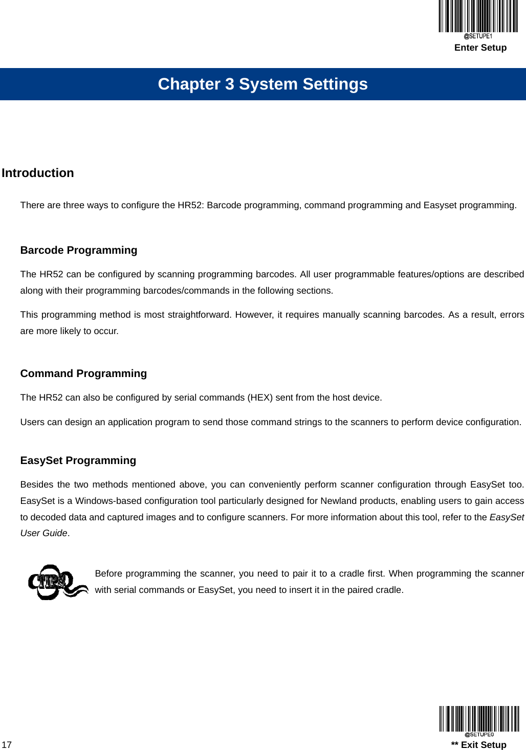
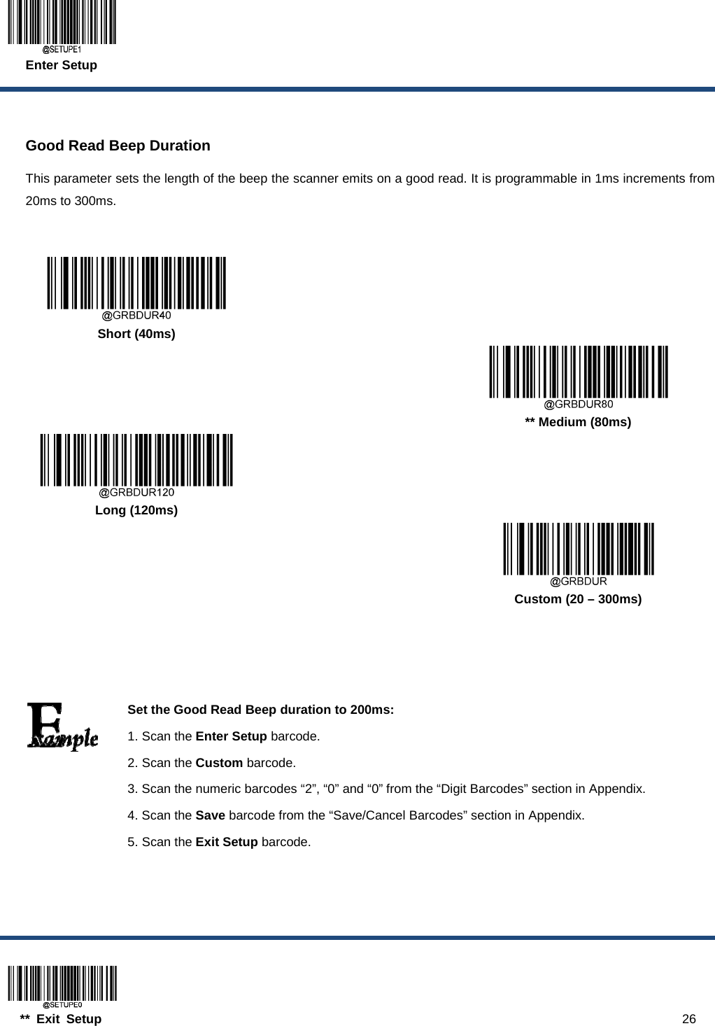
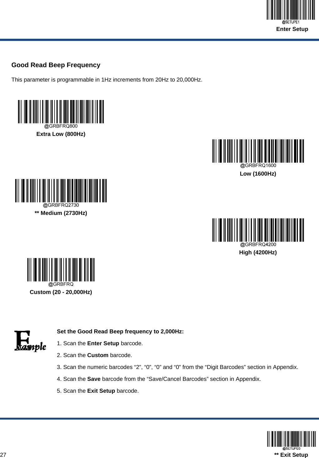
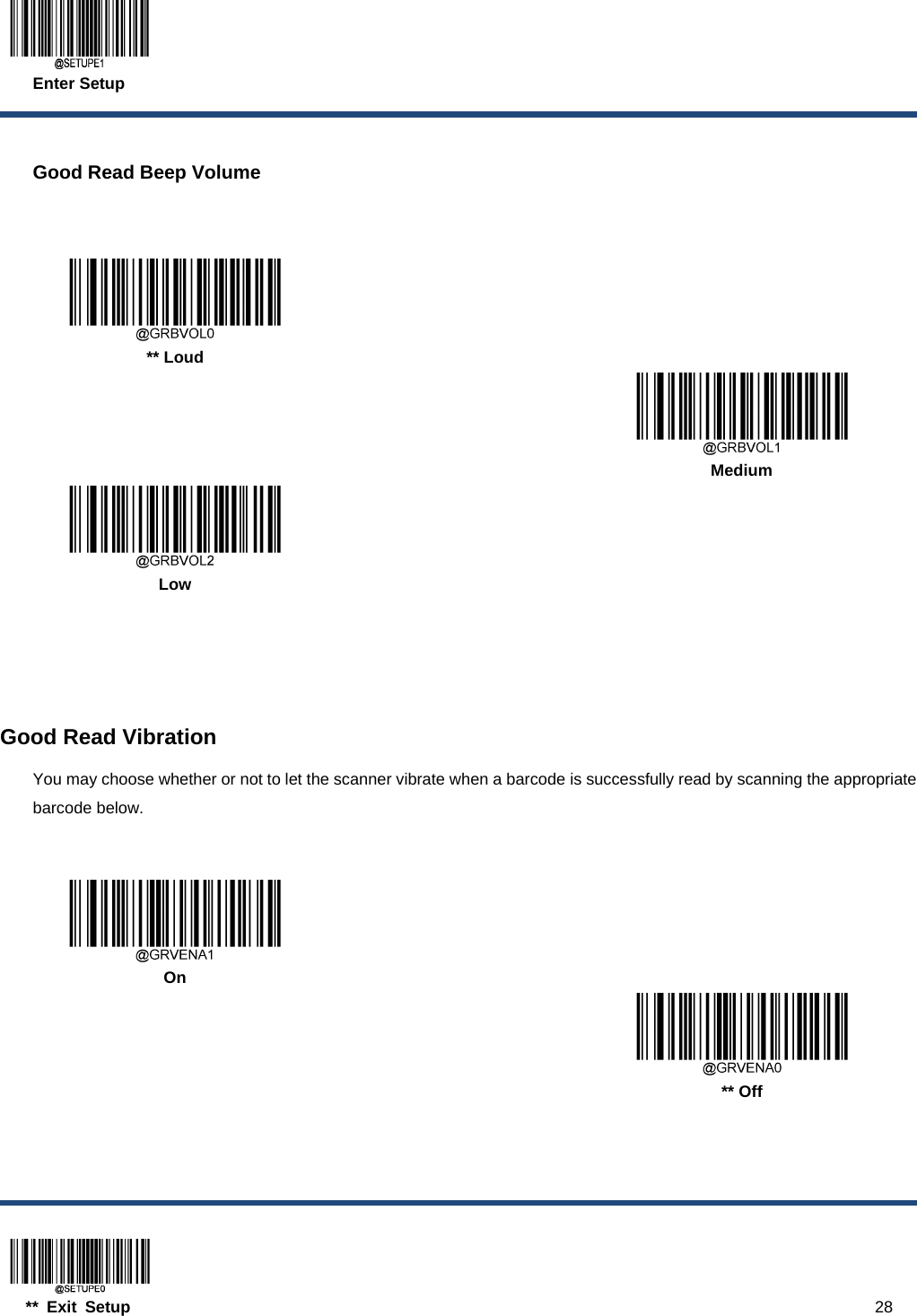
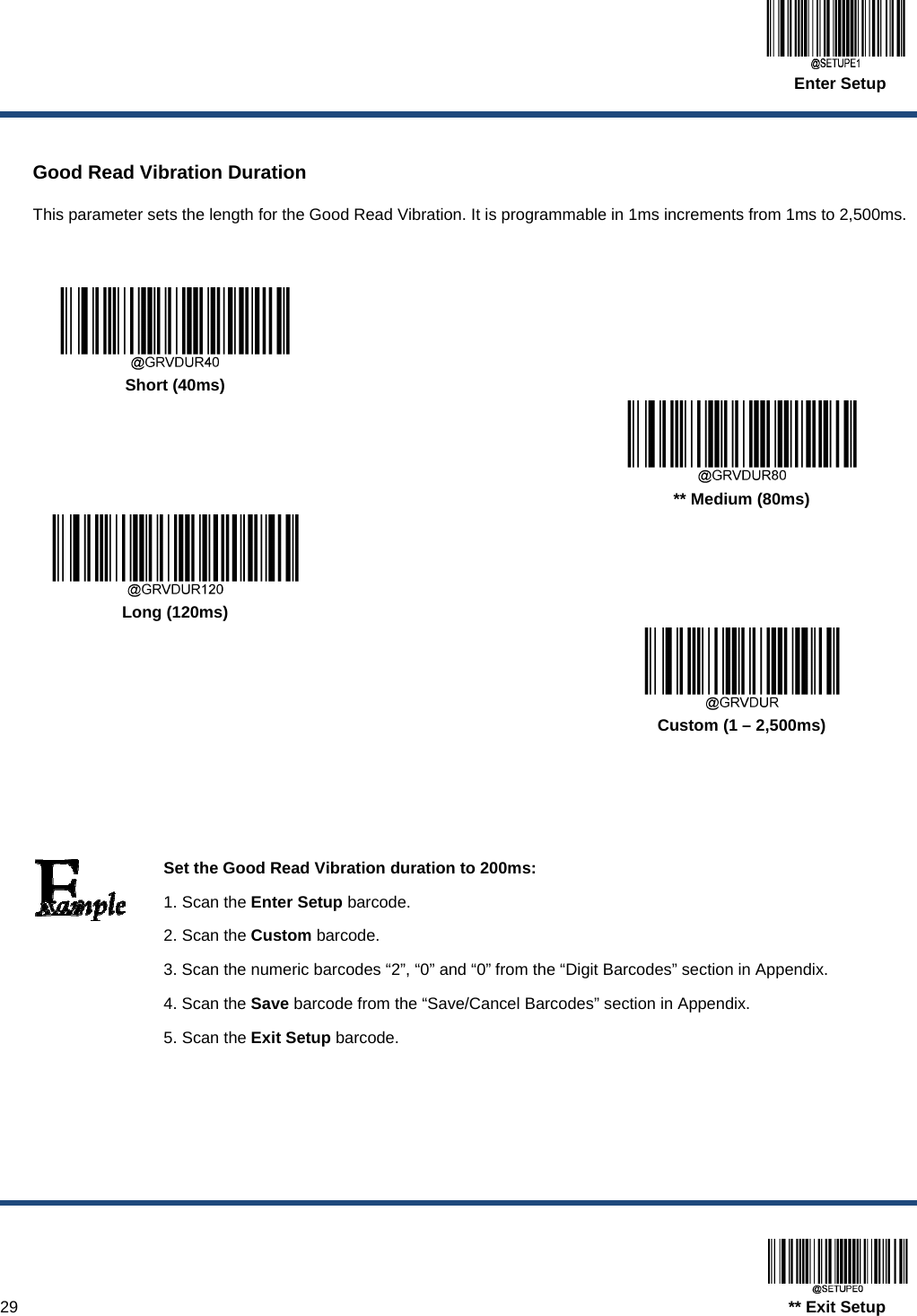
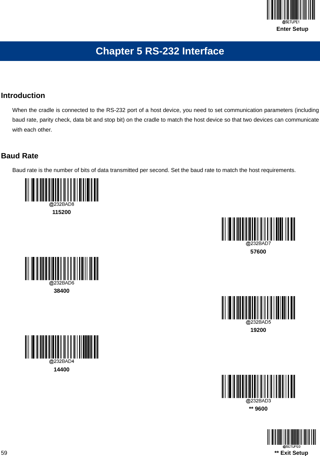
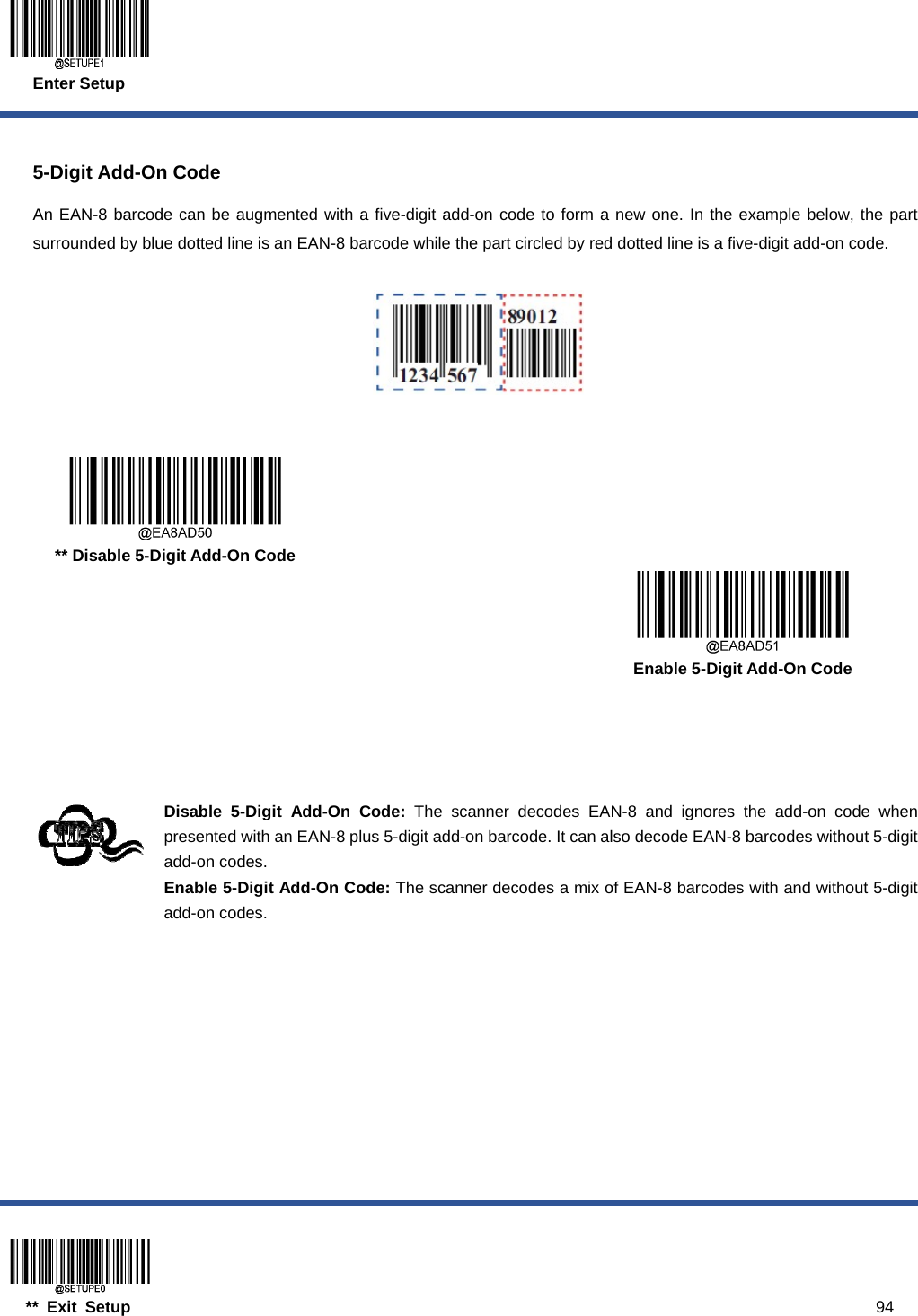
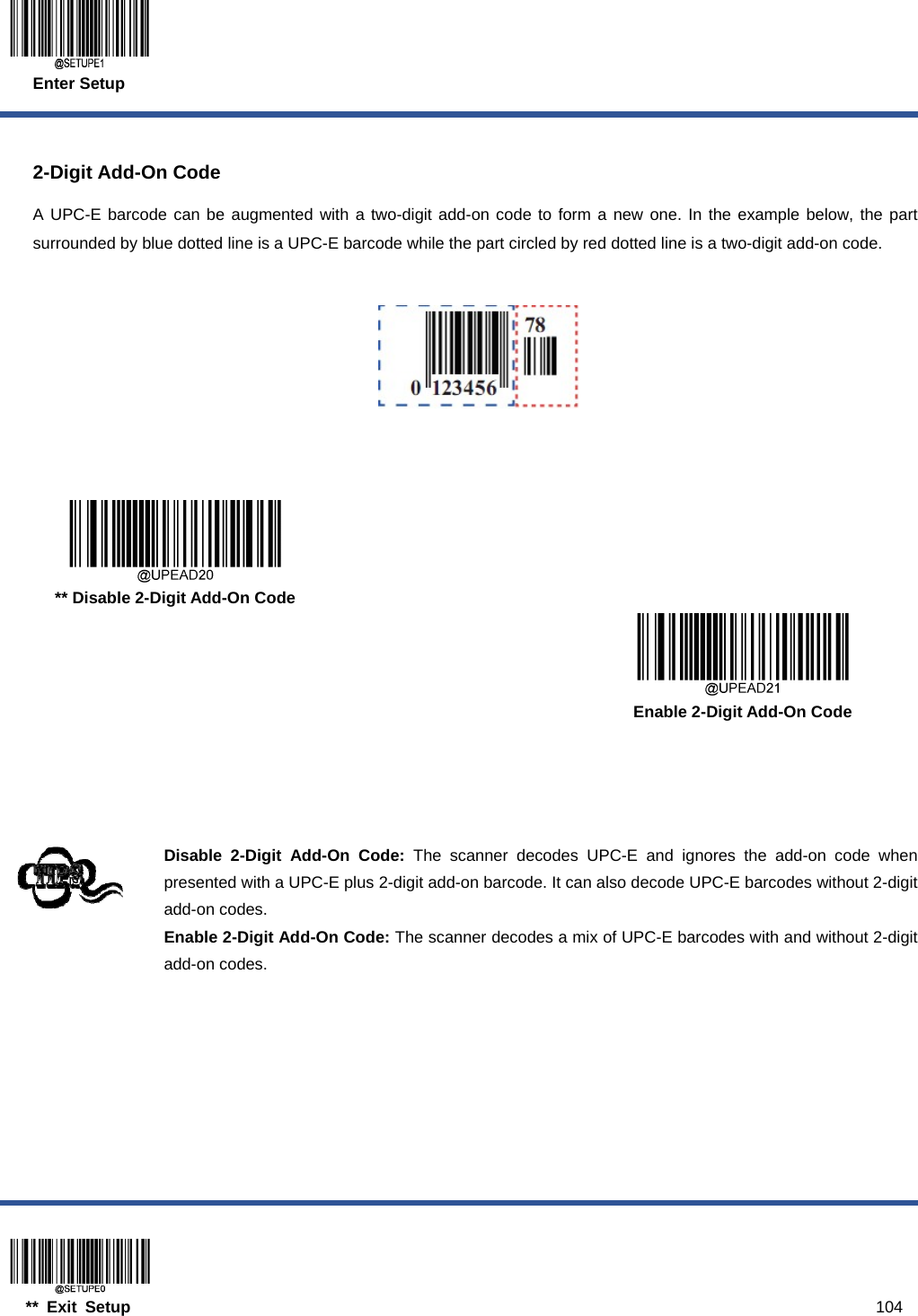
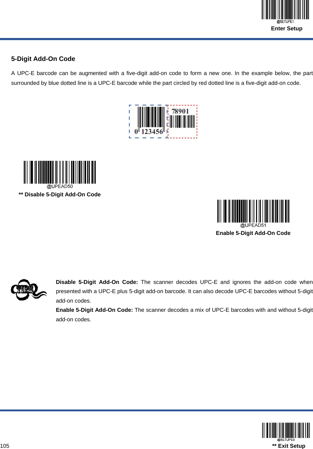
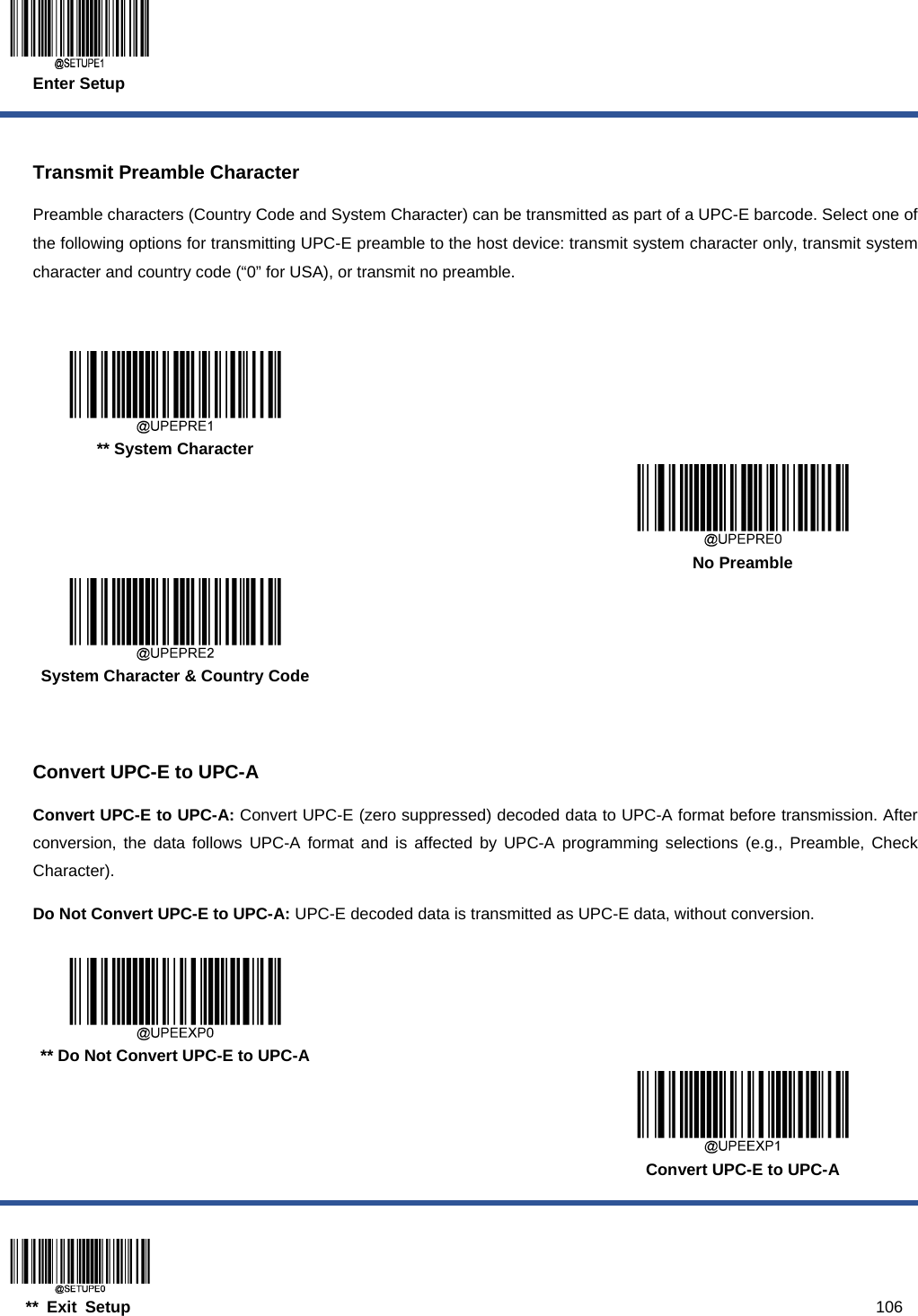
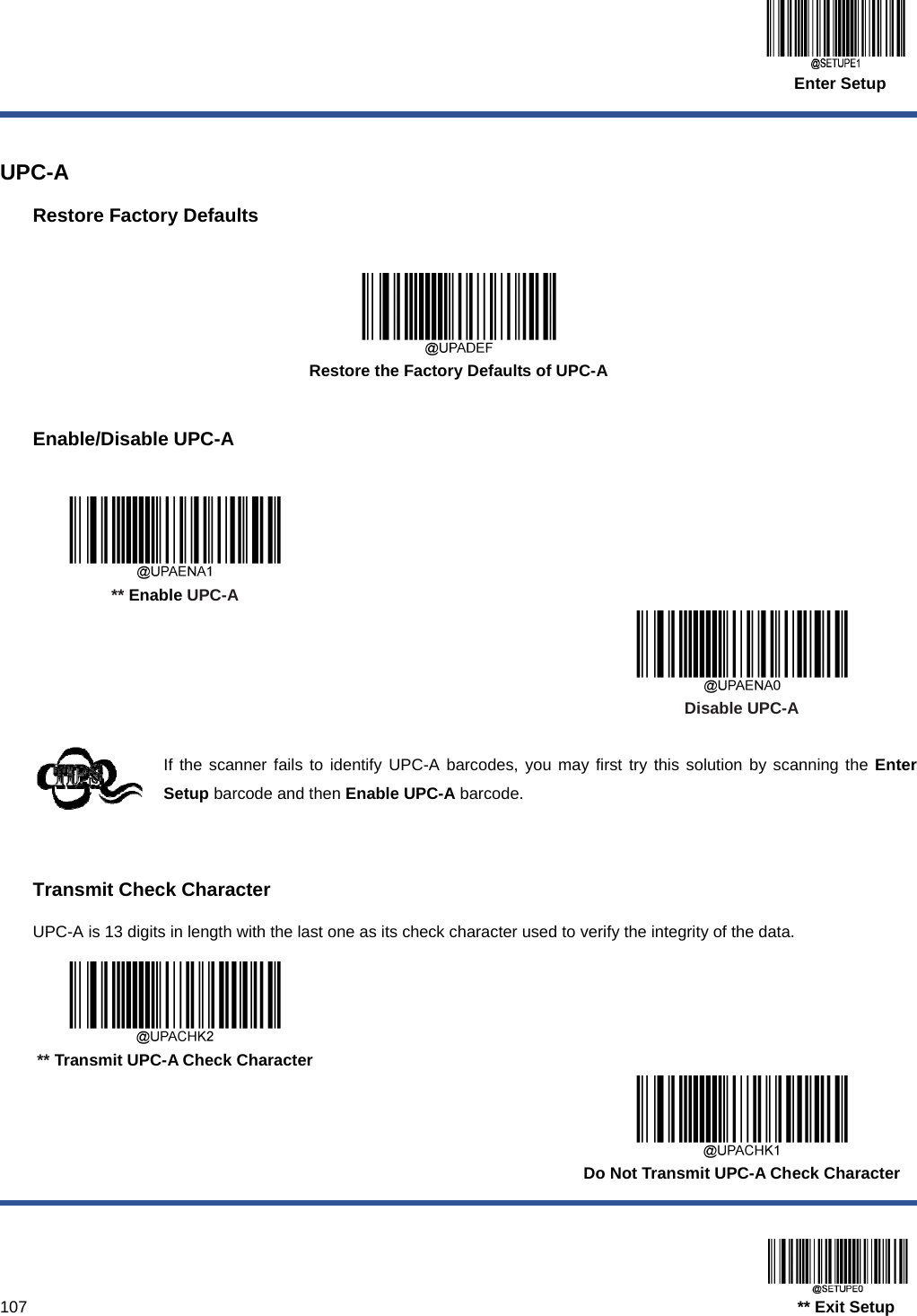
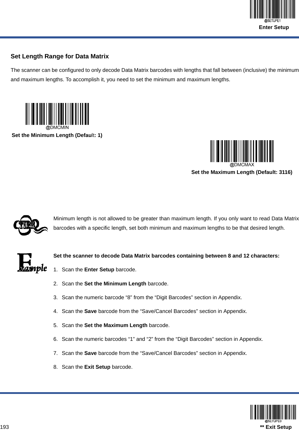
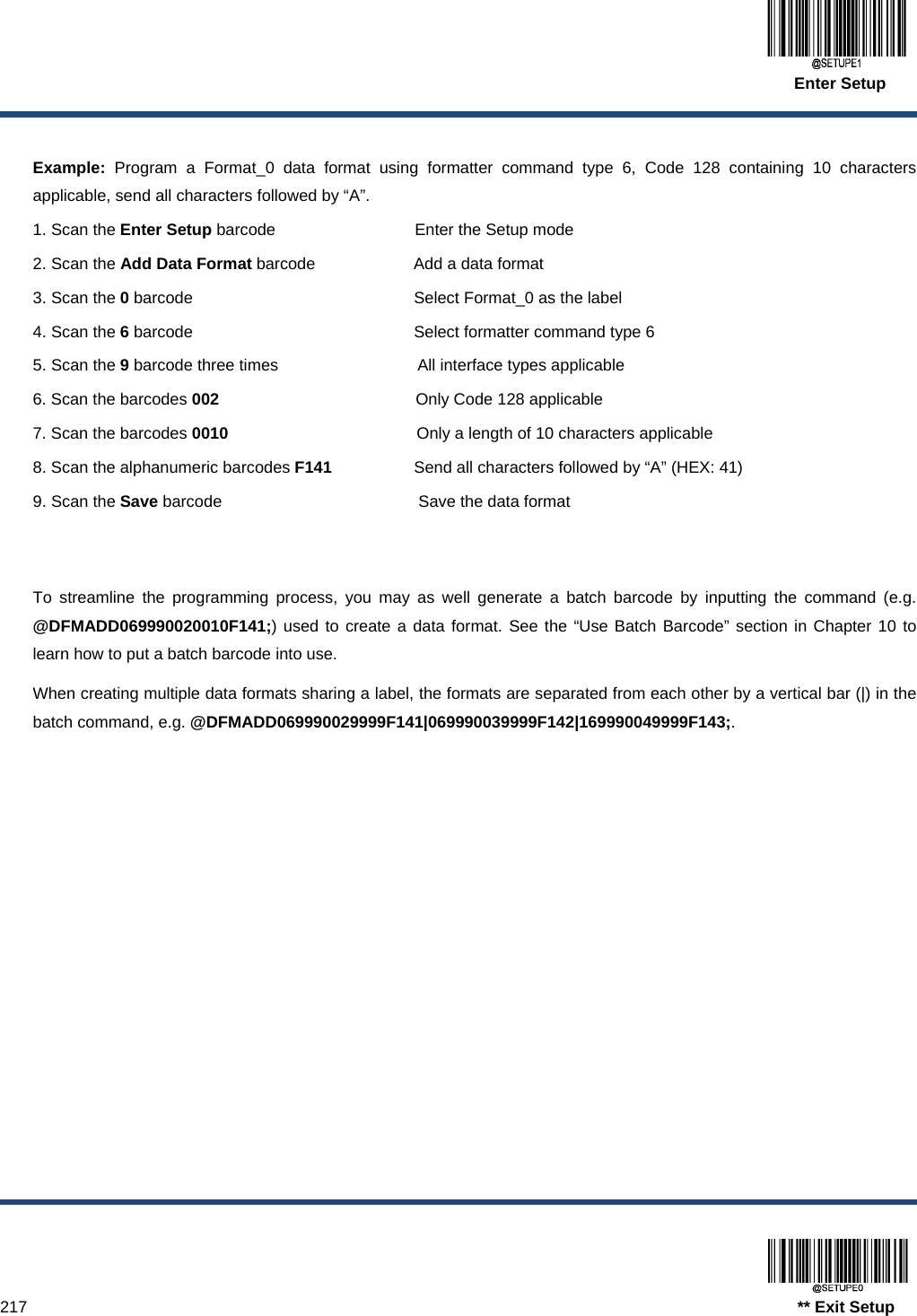
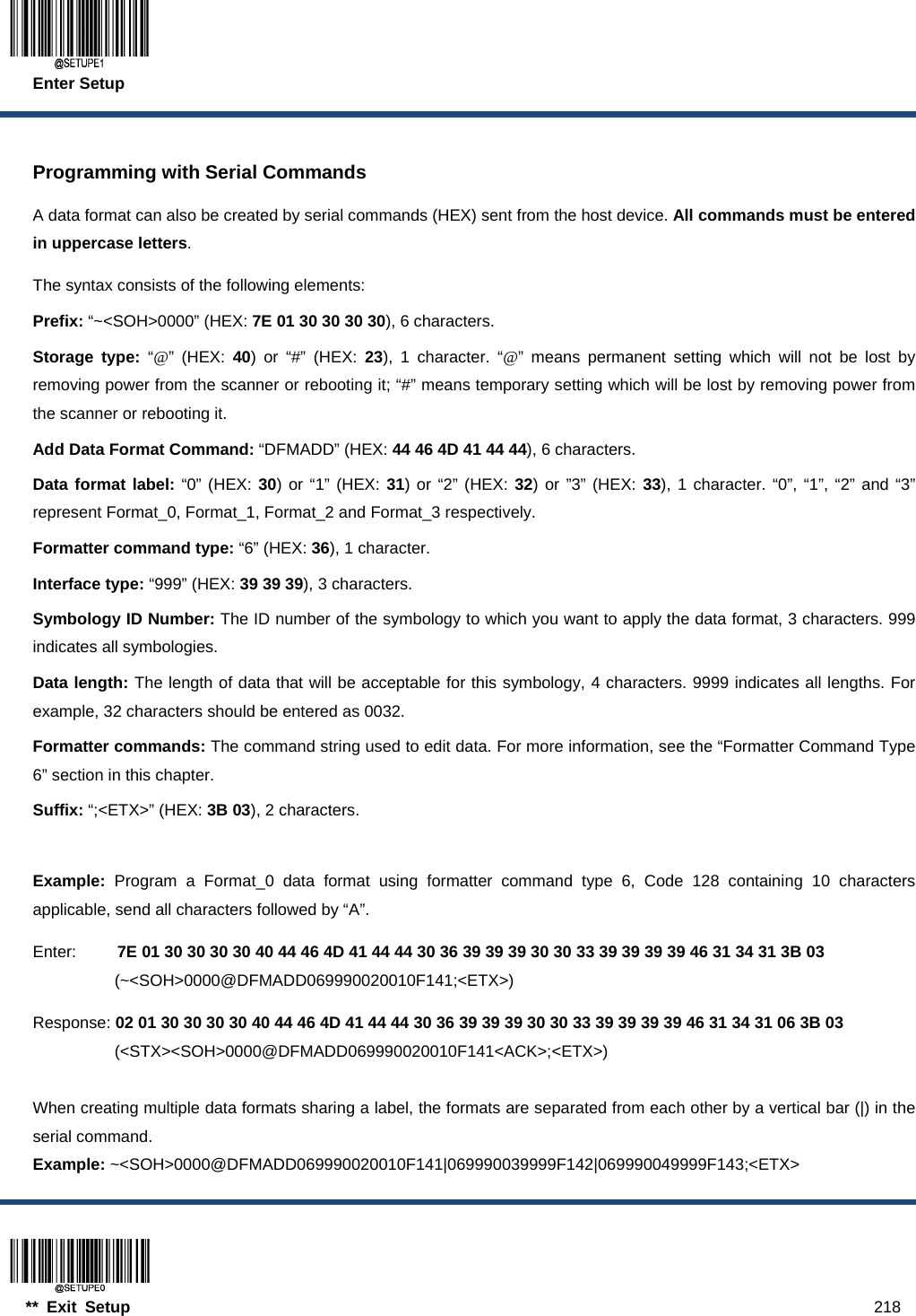
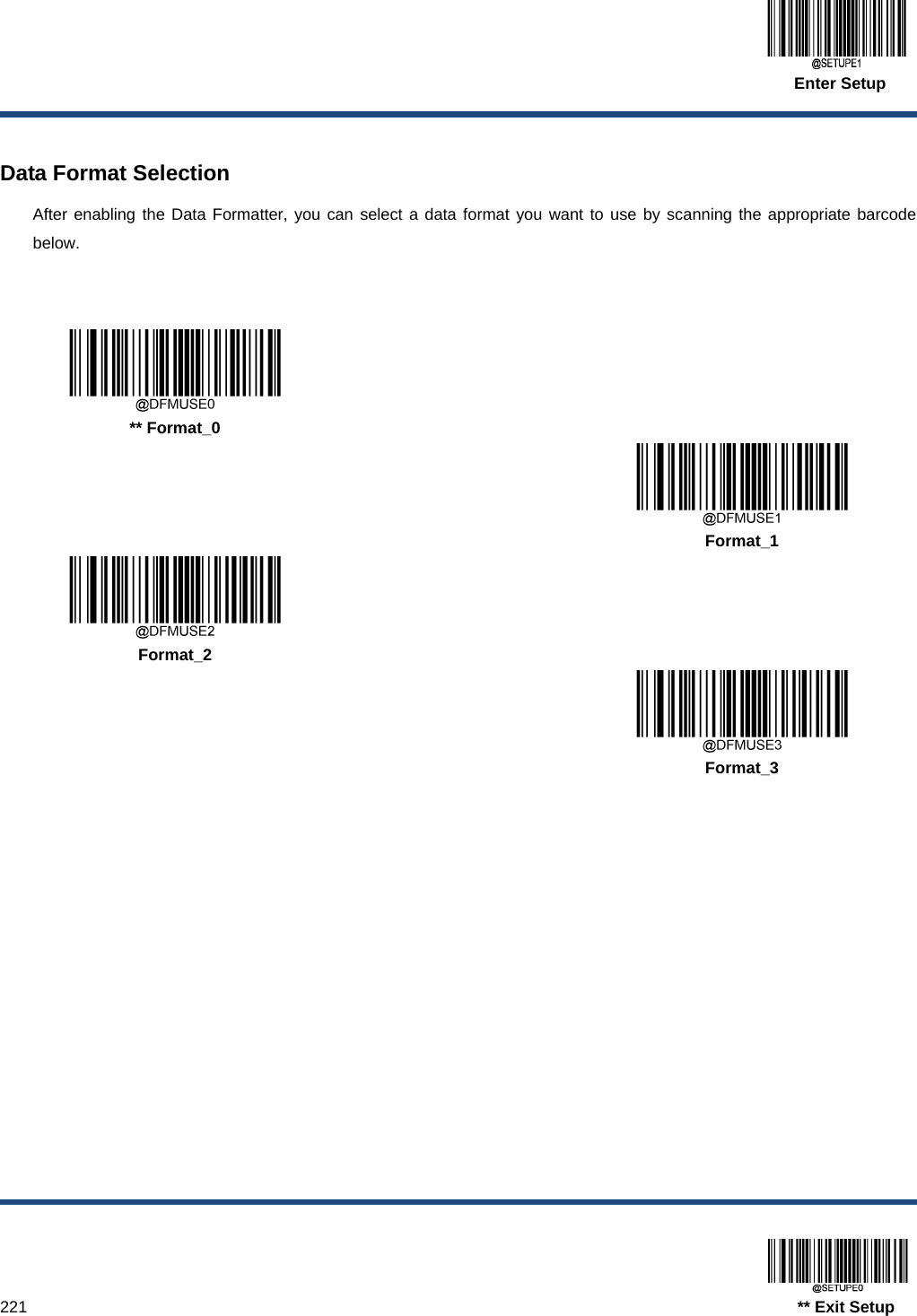
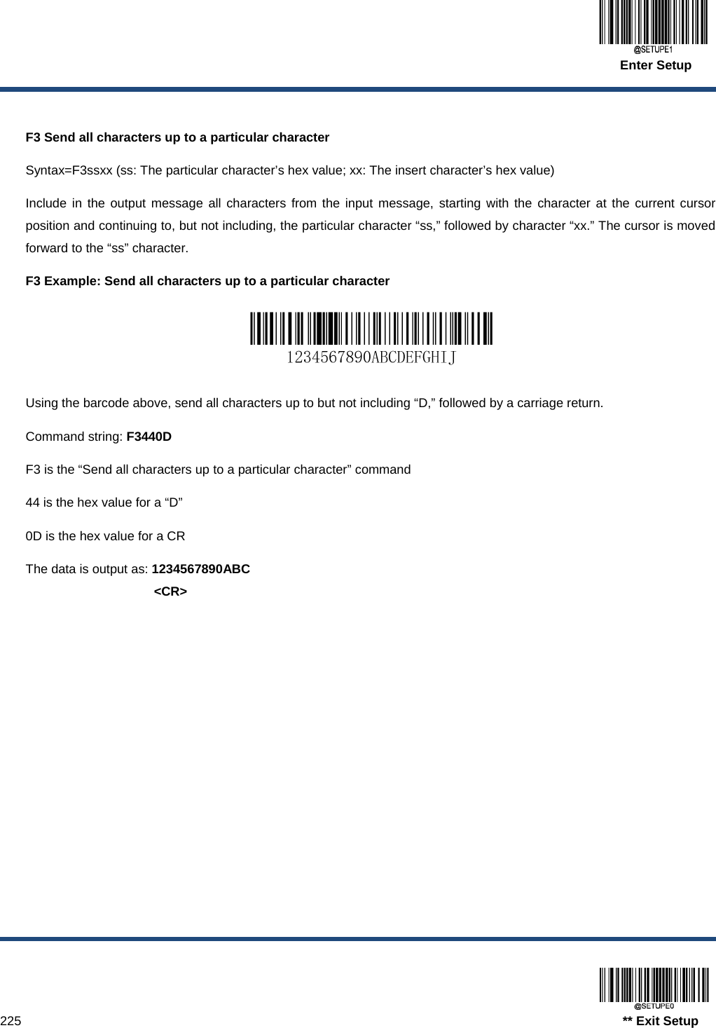
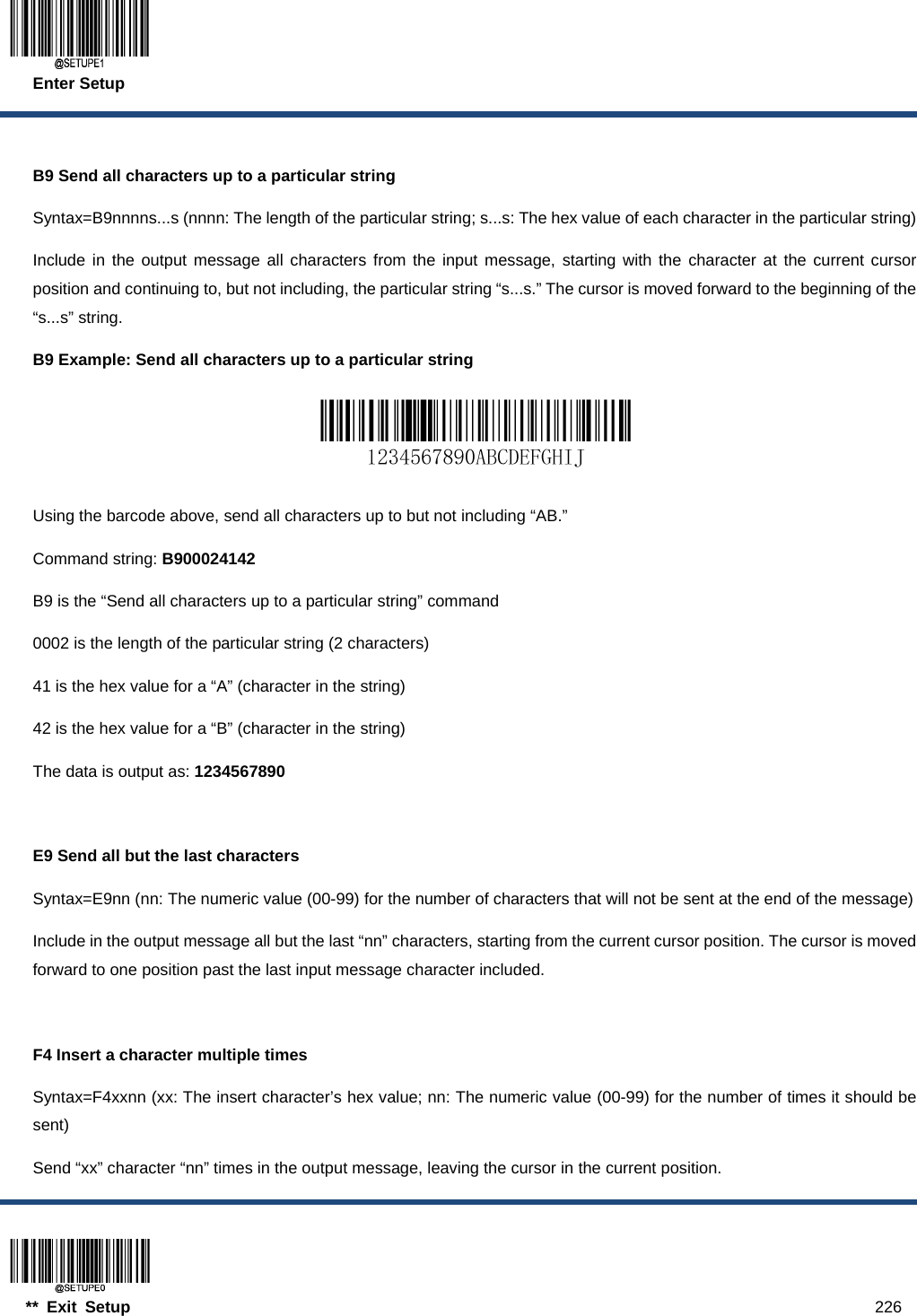
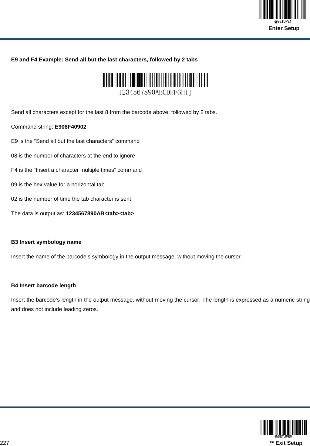
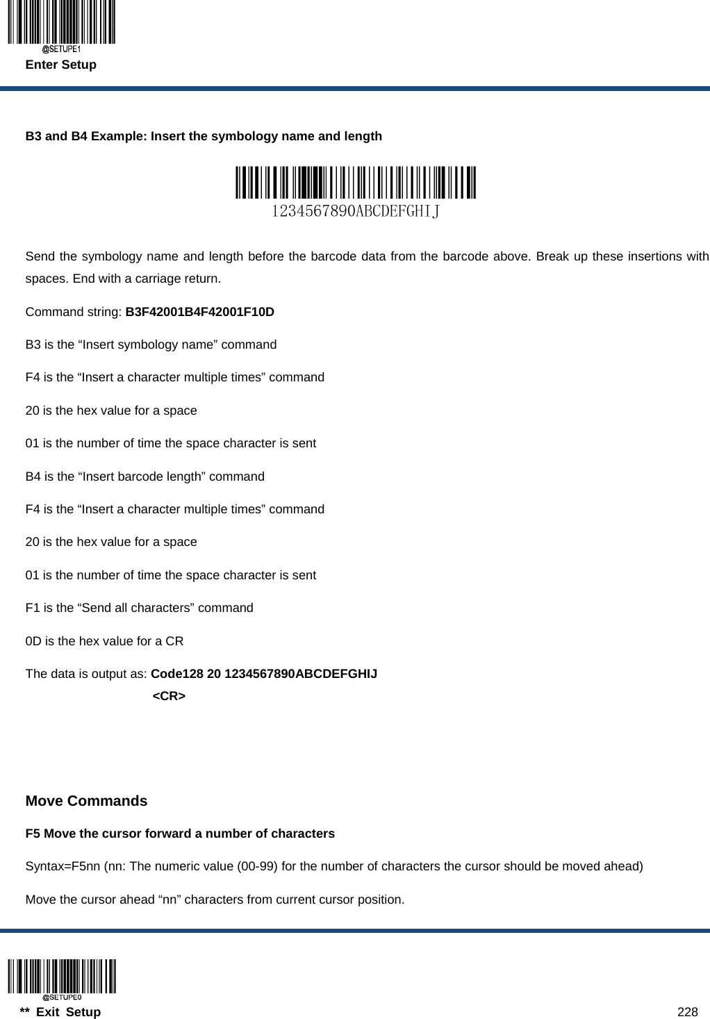
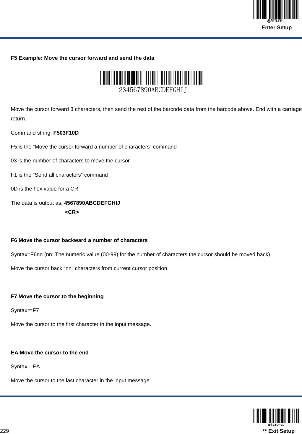
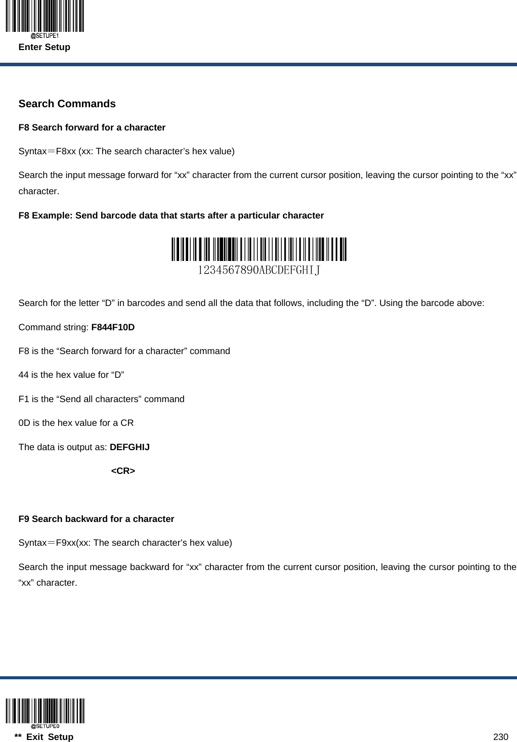
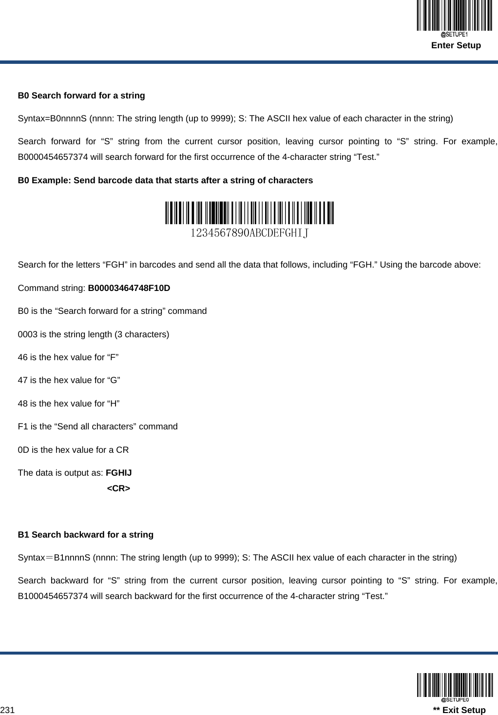
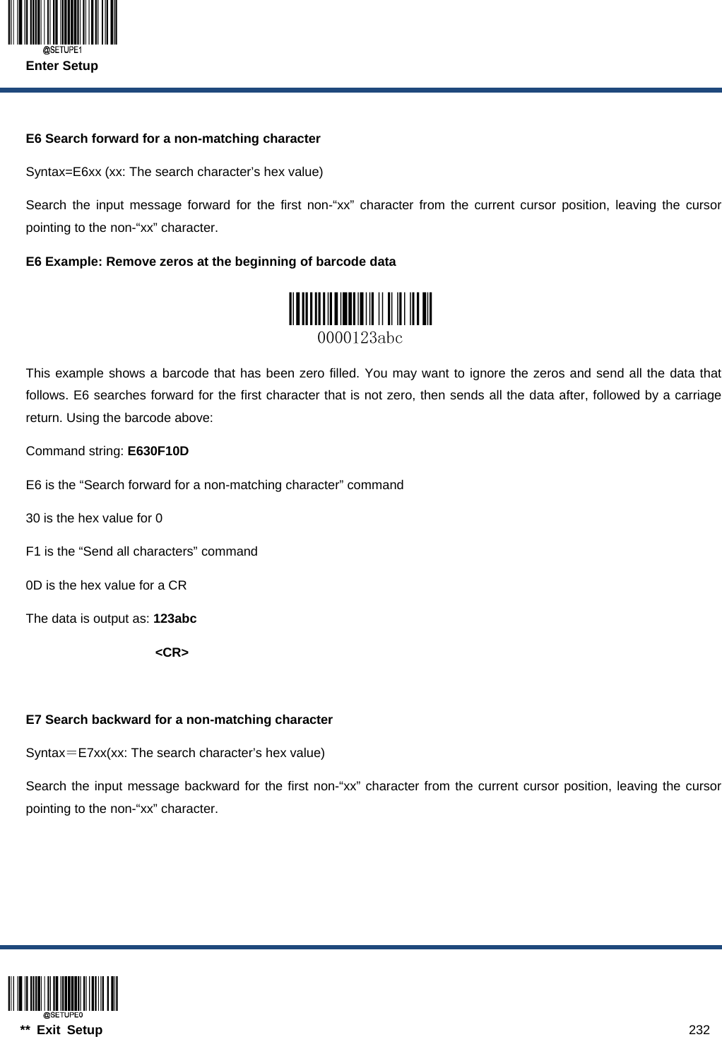
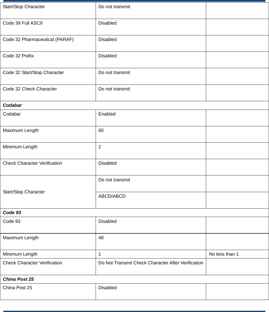
![Enter Setup 19 ** Exit Setup Use of Programming Command Besides the barcode programming method, the scanner can also be configured by serial commands (HEX) sent from the host device. All commands must be entered in uppercase letters. Command Syntax Prefix StorageType Tag SubTag {Data} [,SubTag {Data}] [;Tag SubTag {Data}] […] Suffix Prefix: “~<SOH>0000” (HEX: 7E 01 30 30 30 30), 6 characters. StorageType: “@” (HEX: 40) or “#” (HEX: 23), 1 character. “@” means permanent setting which will not be lost by removing power from the scanner or rebooting it; “#” means temporary setting which will be lost by removing power from the scanner or rebooting it. Tag: A 3-character case-sensitive field that identifies the desired command group. For example, all USB HID Keyboard configuration settings are identified with a Tag of KBW. SubTag: A 3-character case-sensitive field that identifies the desired parameter within the tag group. For example, the SubTag for the keyboard layout is CTY. Data: The value for a feature or parameter setting, identified by the Tag and SubTag. Suffix: “;<ETX>” (HEX: 3B 03), 2 characters. Multiple commands can be issued within one Prefix/Suffix sequence. For configuration commands, only the Tag, SubTag, and Data fields must be repeated for each command in sequence. If an additional command is to be applied to the same Tag, then the command is separated with a comma (,) and only the SubTag and Data fields of the additional commands are issued. If the additional command requires a different Tag field, the command is separated from previous command by a semicolon (;). Query Commands For query commands, the entry in the Data field in the syntax above is one of the following characters means: * (HEX: 2A) What is the scanner’s current value for the setting(s). & (HEX: 26) What is the factory default value for the setting(s). ^ (HEX: 5E) What is the range of possible values for the setting(s).](https://usermanual.wiki/Fujian-Newland-Auto-ID-Tech/NLS-HR52/User-Guide-4129322-Page-35.png)

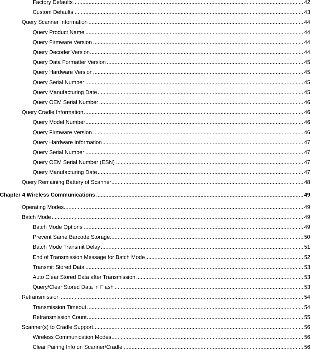
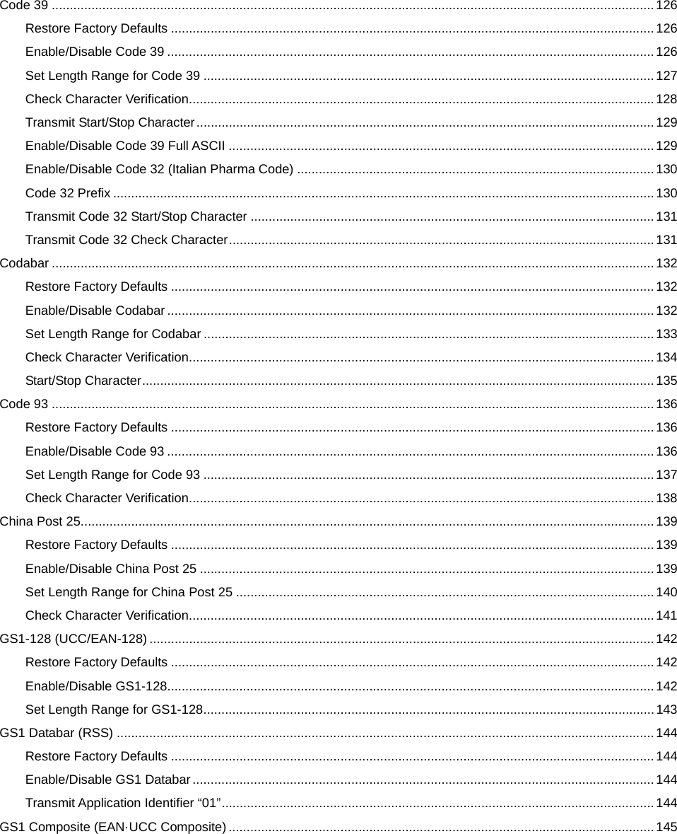
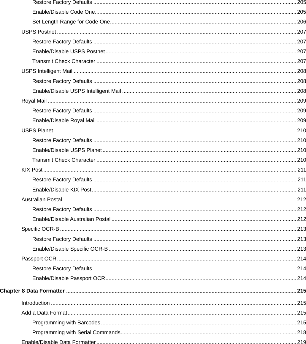
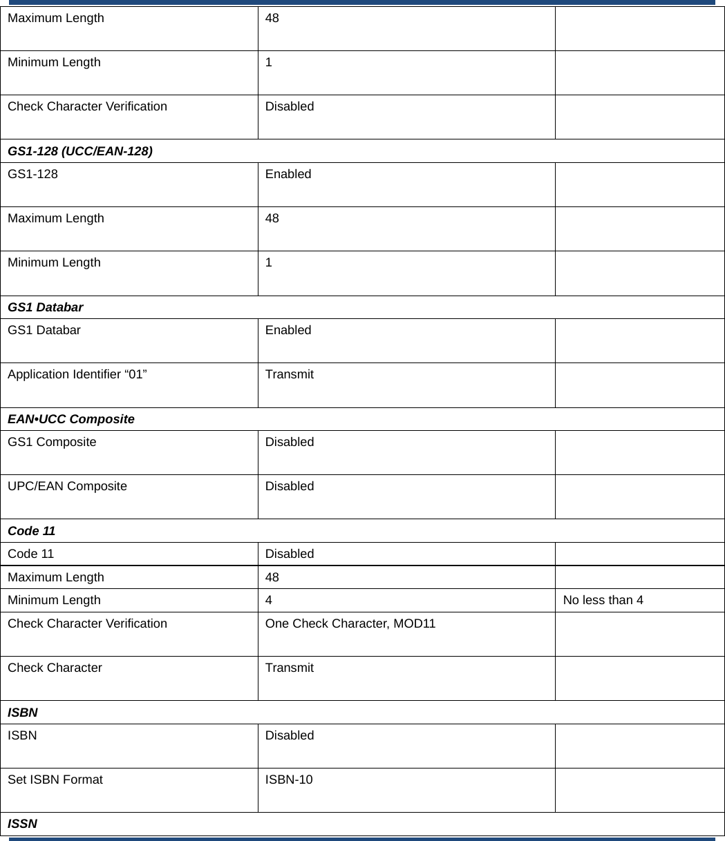
![Enter Setup ** Exit Setup 74 ASCII Function Key Mapping Table ASCII Function ASCII Value (HEX) Function Key Mapping Disabled Ctrl+ASCII NUL 00 Null Ctrl+@ SOH 01 Keypad Enter Ctrl+A STX 02 Caps Lock Ctrl+B ETX 03 ALT Ctrl+C EOT 04 Null Ctrl+D ENQ 05 CTRL Ctrl+E ACK 06 Null Ctrl+F BEL 07 Enter Ctrl+G BS 08 Left Arrow Ctrl+H HT 09 Horizontal Tab Ctrl+I LF 0A Down Arrow Ctrl+J VT 0B Vertical Tab Ctrl+K FF 0C Delete Ctrl+L CR 0D Enter Ctrl+M SO 0E Insert Ctrl+N SI 0F Esc Ctrl+O DLE 10 F11 Ctrl+P DC1 11 Home Ctrl+Q DC2 12 PrintScreen Ctrl+R DC3 13 Backspace Ctrl+S DC4 14 tab+shift Ctrl+T NAK 15 F12 Ctrl+U SYN 16 F1 Ctrl+V ETB 17 F2 Ctrl+W CAN 18 F3 Ctrl+X EM 19 F4 Ctrl+Y SUB 1A F5 Ctrl+Z ESC 11 F6 Ctrl+[ FS 1C F7 Ctrl+\ GS 1D F8 Ctrl+] RS 1E F9 Ctrl+6 US 1F F10 Ctrl+-](https://usermanual.wiki/Fujian-Newland-Auto-ID-Tech/NLS-HR52/User-Guide-4129322-Page-90.png)
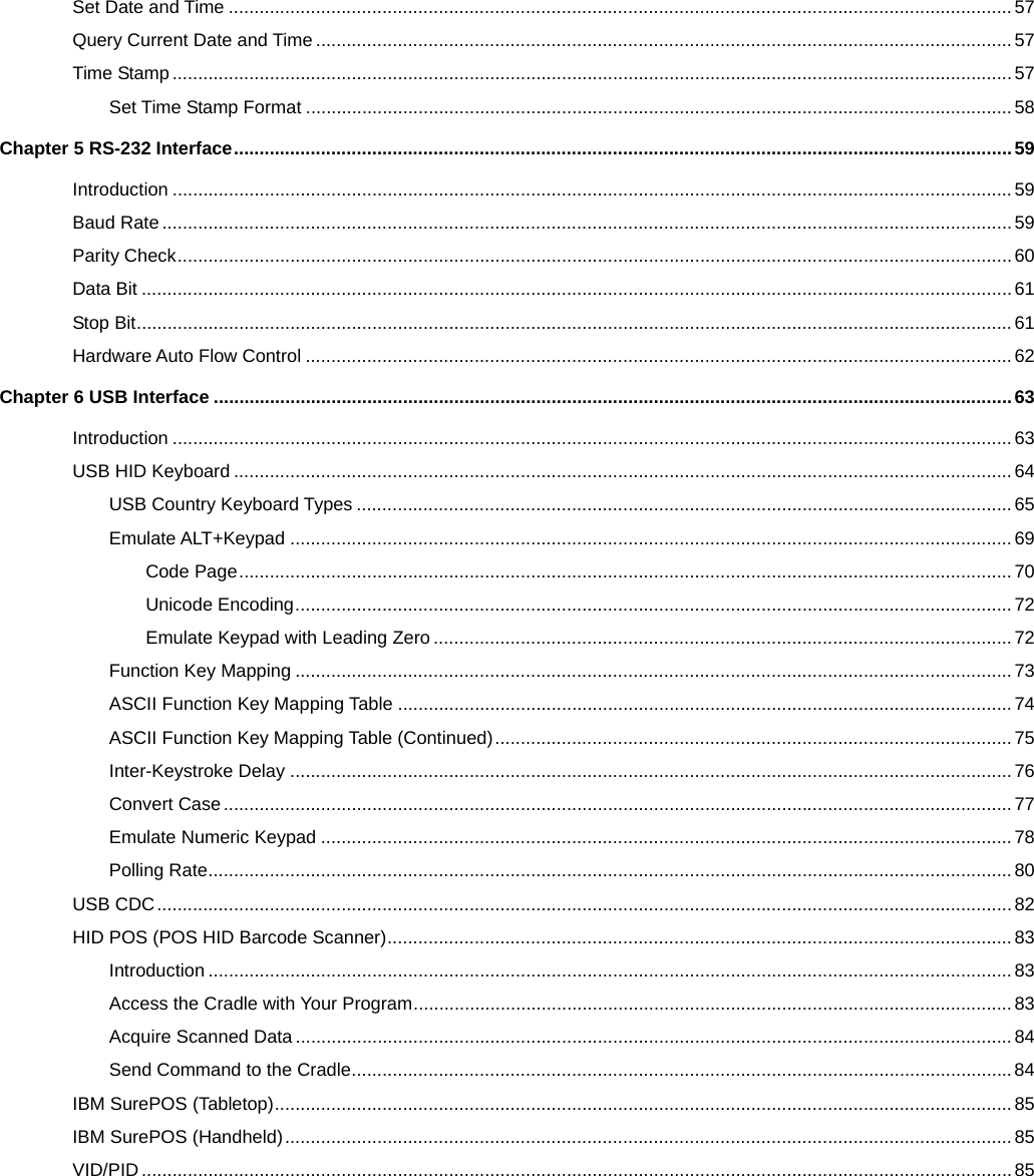
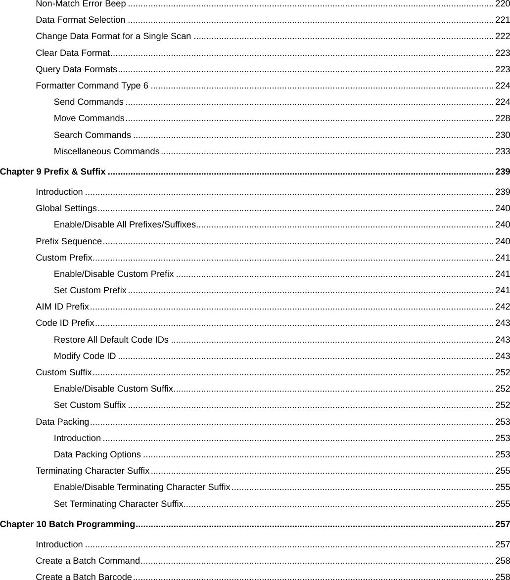
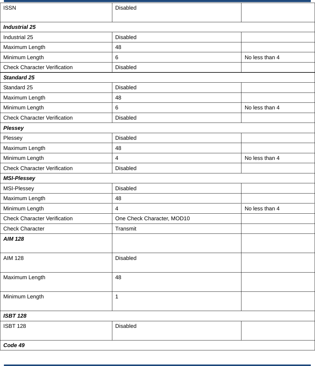
![Enter Setup 75 ** Exit Setup ASCII Function Key Mapping Table (Continued) The last five characters (0x1B~0x1F) in the table above apply to US keyboard layout only. The following chart provides the equivalents of these five characters for other countries. Country Ctrl+ASCII United States Ctrl+[ Ctrl+\ Ctrl+] Ctrl+6 Ctrl+- Belgium Ctrl+[ Ctrl+< Ctrl+] Ctrl+6 Ctrl+- Scandinavia Ctrl+8 Ctrl+< Ctrl+9 Ctrl+6 Ctrl+- France Ctrl+^ Ctrl+8 Ctrl+$ Ctrl+6 Ctrl+= Germany Ctrl+Ã Ctrl++ Ctrl+6 Ctrl+- Italy Ctrl+\ Ctrl++ Ctrl+6 Ctrl+- Switzerland Ctrl+< Ctrl+.. Ctrl+6 Ctrl+- United Kingdom Ctrl+[ Ctrl+¢ Ctrl+] Ctrl+6 Ctrl+- Denmark Ctrl+8 Ctrl+\ Ctrl+9 Ctrl+6 Ctrl+- Norway Ctrl+8 Ctrl+\ Ctrl+9 Ctrl+6 Ctrl+- Spain Ctrl+[ Ctrl+\ Ctrl+] Ctrl+6 Ctrl+-](https://usermanual.wiki/Fujian-Newland-Auto-ID-Tech/NLS-HR52/User-Guide-4129322-Page-91.png)


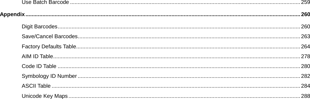
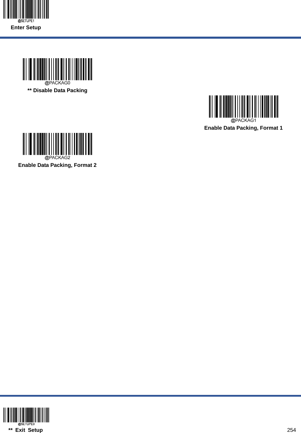
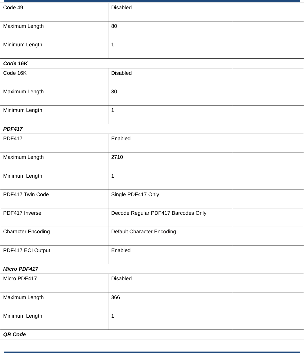
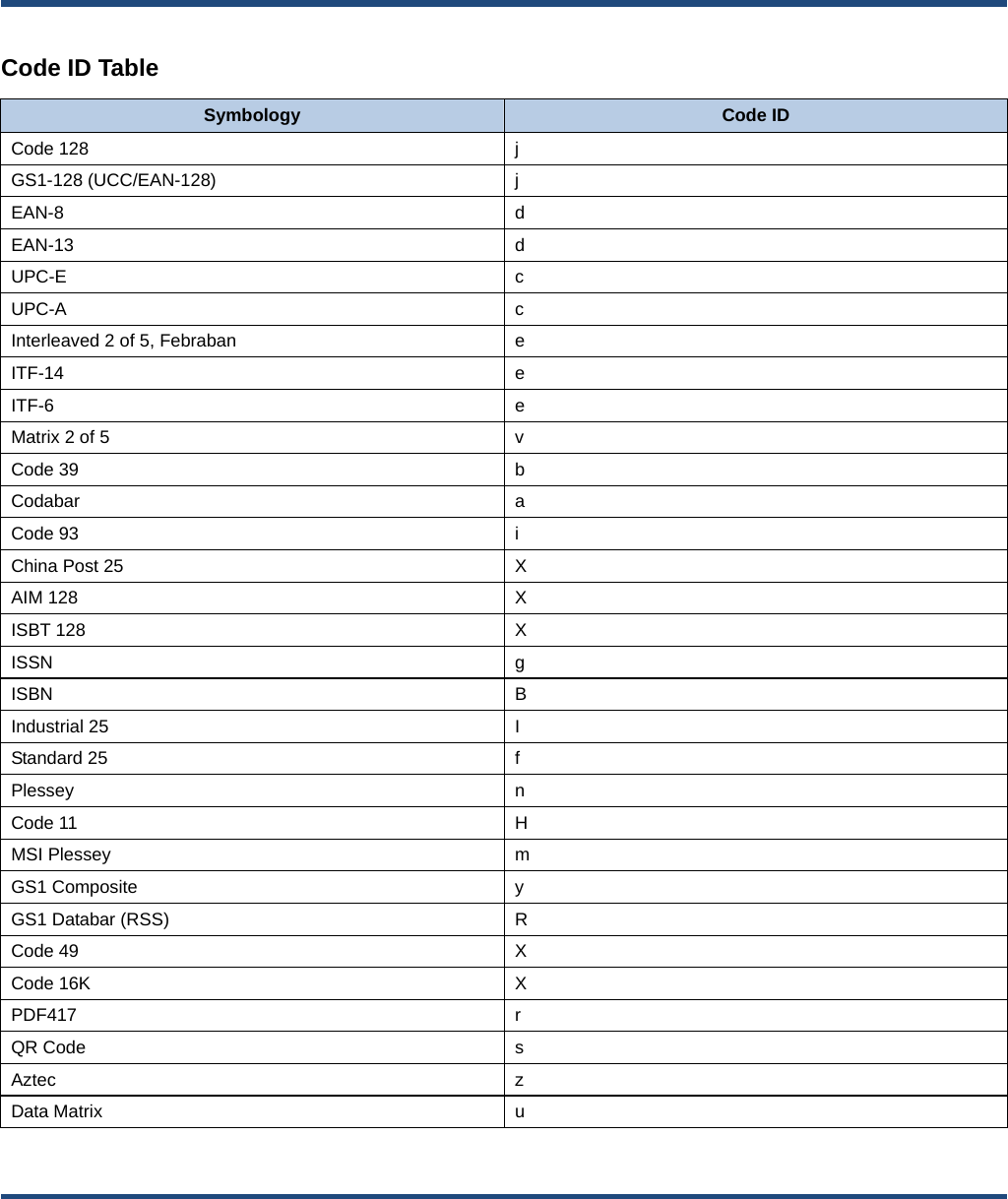
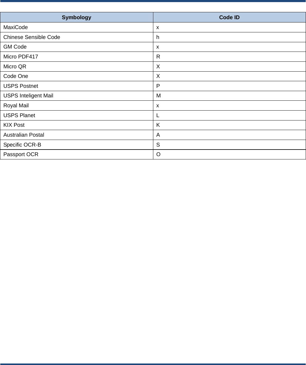
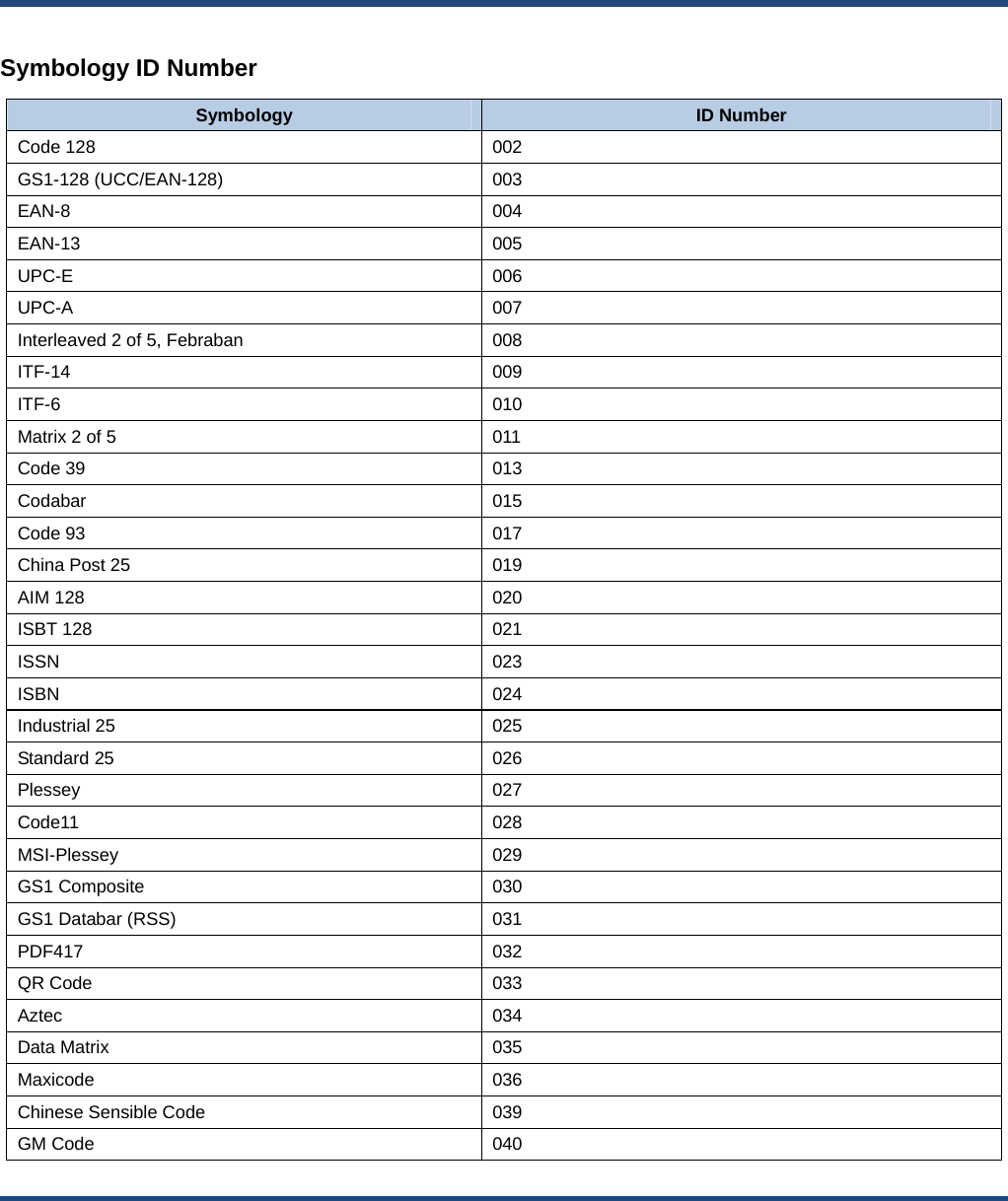
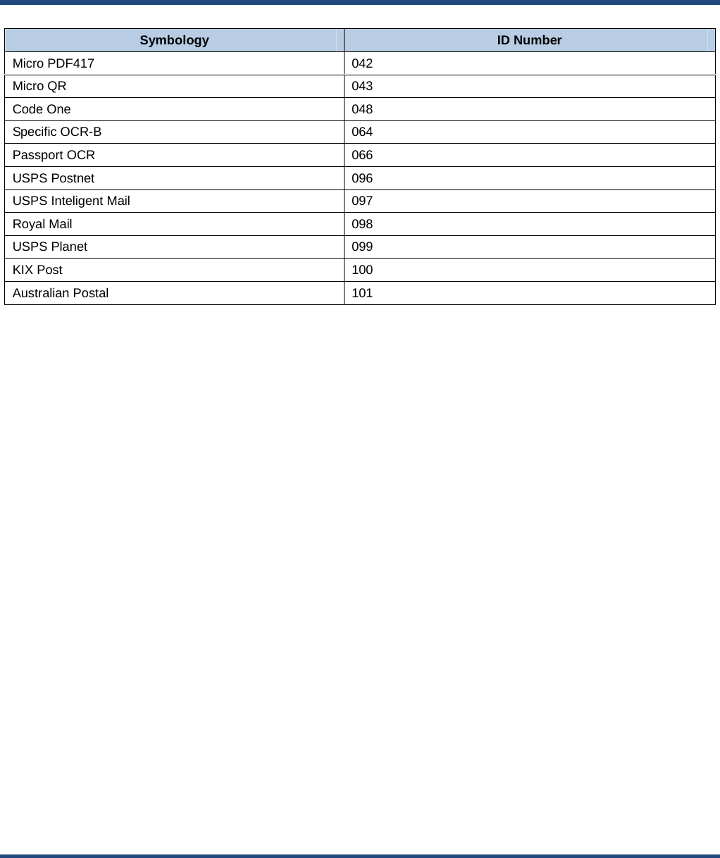
![Enter Setup 253 ** Exit Setup Data Packing Introduction Data packing is designed for a specific group of users who want to have the data packed before transmission. Data packing influences data format, so it is advised to disable this feature when it is not required. Data Packing Options Disable Data Packing: Transmit decoded data in raw format (unpacketed). Enable Data Packing, Format 1: Transmit decoded data with the packet format 1 defined below. Packet format 1: [STX + ATTR + LEN] + [AL_TYPE + DATA] + [LRC] STX: 0x02 ATTR: 0x00 LEN: Barcode data length is expressed in 2 bytes ranging from 0x0000 (0) to 0xFFFF (65535). AL_TYPE: 0x36 DATA: Raw barcode data. LRC: Check digit. LRC calculation algorithm: computation sequence: 0xFF+LEN+AL_TYPE+DATA; computation method is XOR, byte by byte. Enable Data Packing, Format 2: Transmit decoded data with the packet format 2 defined below. Packet format 2: [STX + ATTR + LEN] + [AL_TYPE] + [Symbology_ID + DATA] + [LRC] STX: 0x02 ATTR: 0x00 LEN: Barcode data length is expressed in 2 bytes ranging from 0x0000 (0) to 0xFFFF (65535). AL_TYPE: 0x3B Symbology_ID: The ID number of symbology, 1 byte. DATA: Raw barcode data. LRC: Check digit. LRC calculation algorithm: computation sequence: 0xFF+LEN+AL_TYPE+Symbology_ID+DATA; computation method is XOR, byte by byte.](https://usermanual.wiki/Fujian-Newland-Auto-ID-Tech/NLS-HR52/User-Guide-4129322-Page-269.png)
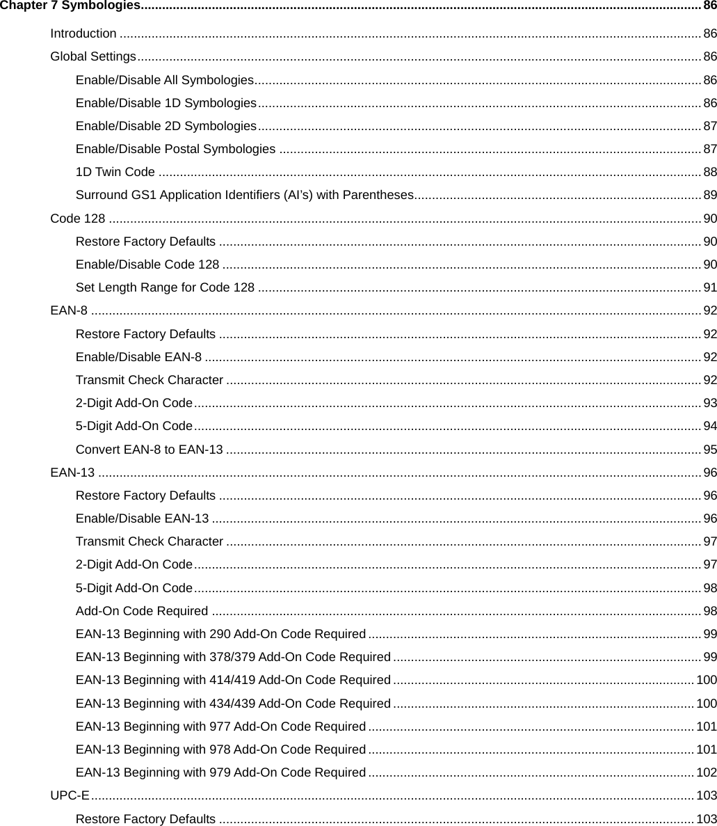
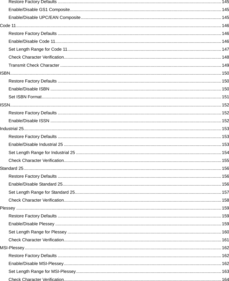
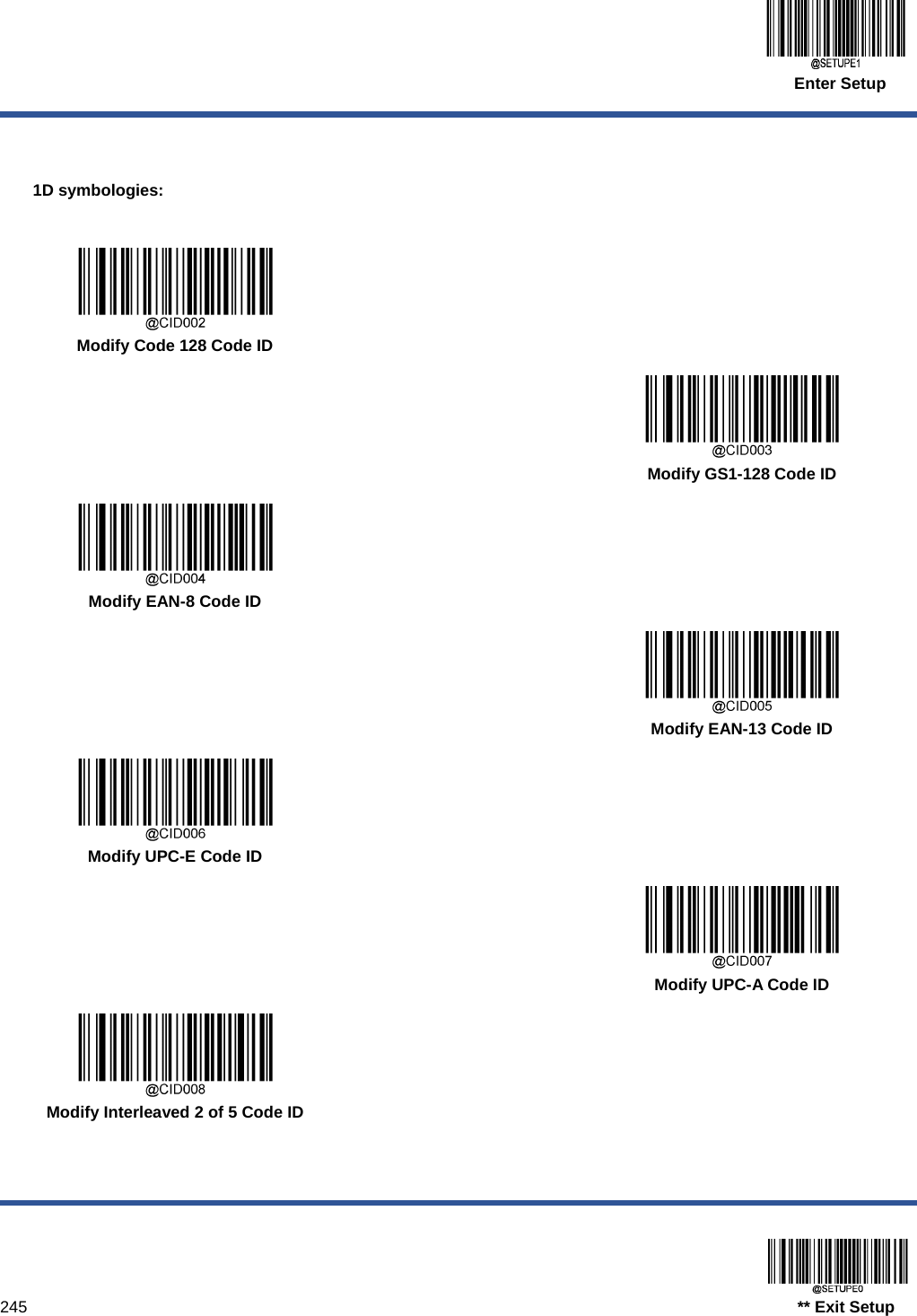
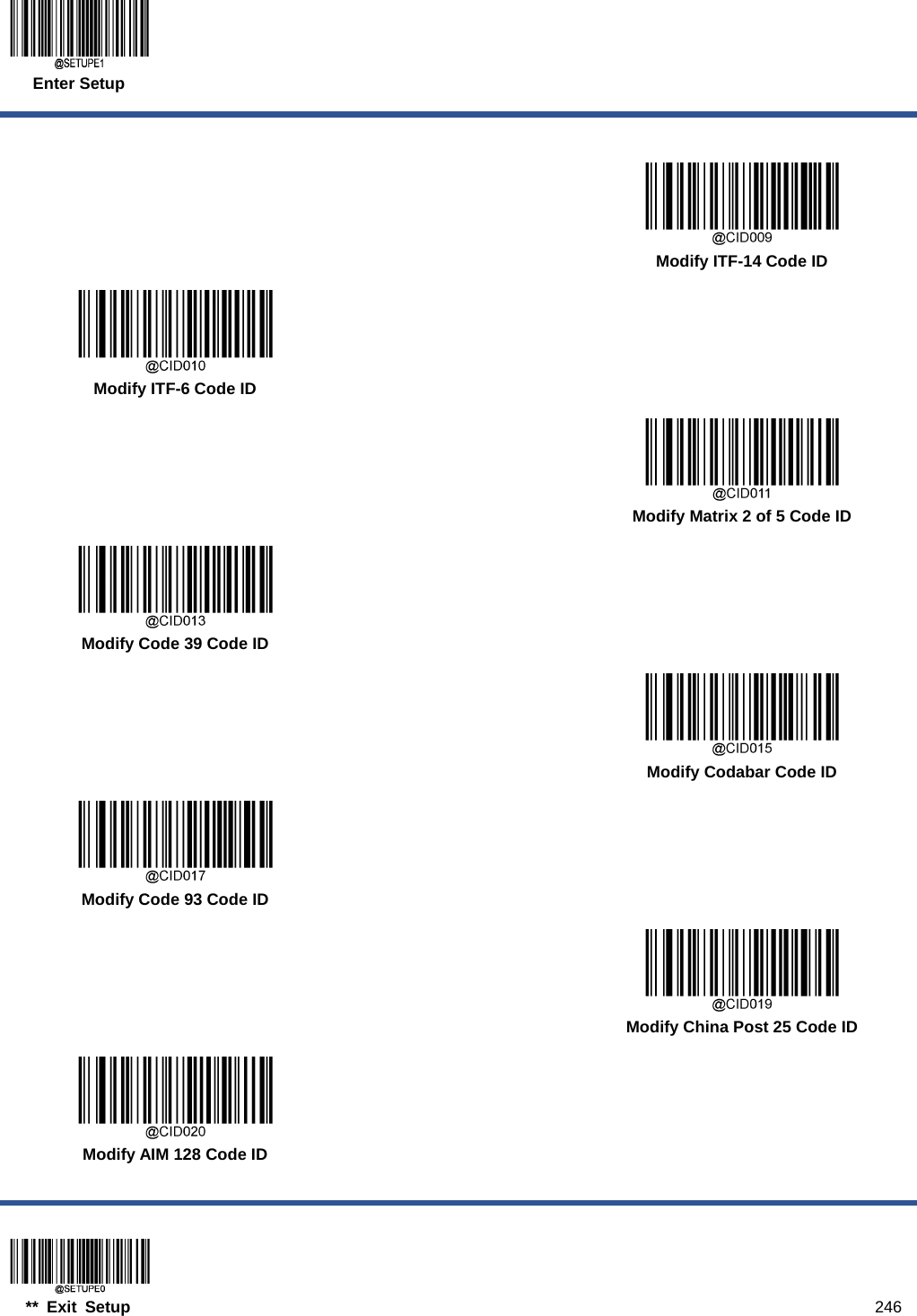
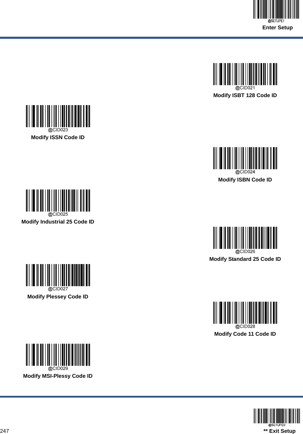
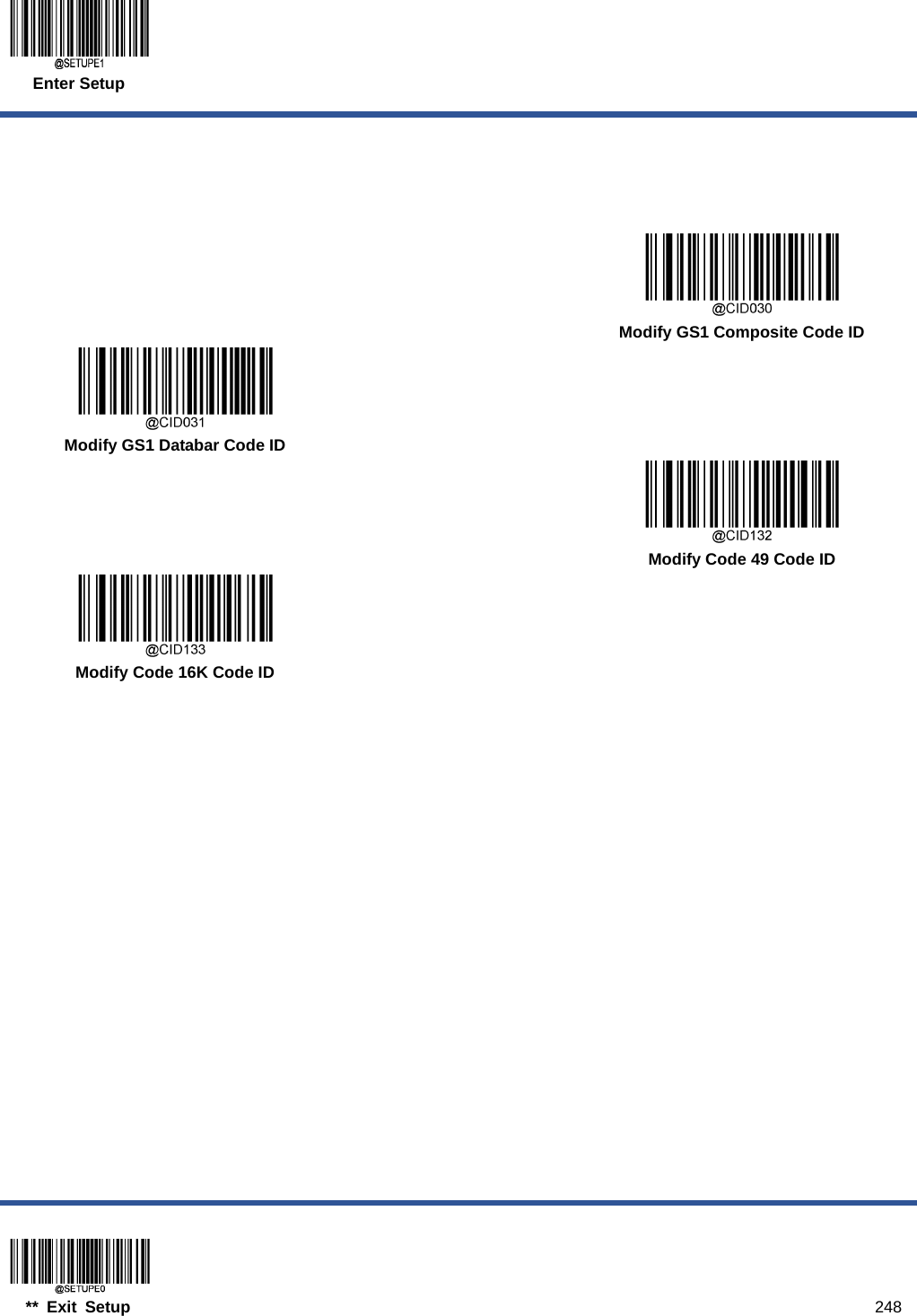
![AIM ID Table Symbology AIM ID Possible AIM ID Modifiers (m) Code 128 ]C0 GS1-128 (UCC/EAN-128) ]C1 EAN-8 ]E4 EAN-8 with Addon ]E3 EAN-13 ]E0 EAN-13 with Addon ]E3 UPC-E ]E0 UPC-E with Addon ]E3 UPC-A ]E0 UPC-A with Addon ]E3 Interleaved 2 of 5, Febraban ]Im 0, 1, 3 ITF-14 ]Im 1, 3 ITF-6 ]Im 1, 3 Matrix 2 of 5 ]X0 Code 39 ]Am 0, 1, 3, 4, 5, 7 Codabar ]Fm 0, 2, 4 Code 93 ]G0 China Post 25 ]X0 AIM 128 ]C2 ISBT 128 ]C4 ISSN ]X0 ISBN ]X0 Industrial 25 ]S0 Standard 25 ]R0 Plessey ]P0 Code 11 ]Hm 0, 1, 3 MSI Plessey ]Mm 0, 1 GS1 Composite ]em 0-3 GS1 Databar (RSS) ]e0 Code 49 ]T0 Code 16K ]K0](https://usermanual.wiki/Fujian-Newland-Auto-ID-Tech/NLS-HR52/User-Guide-4129322-Page-294.png)
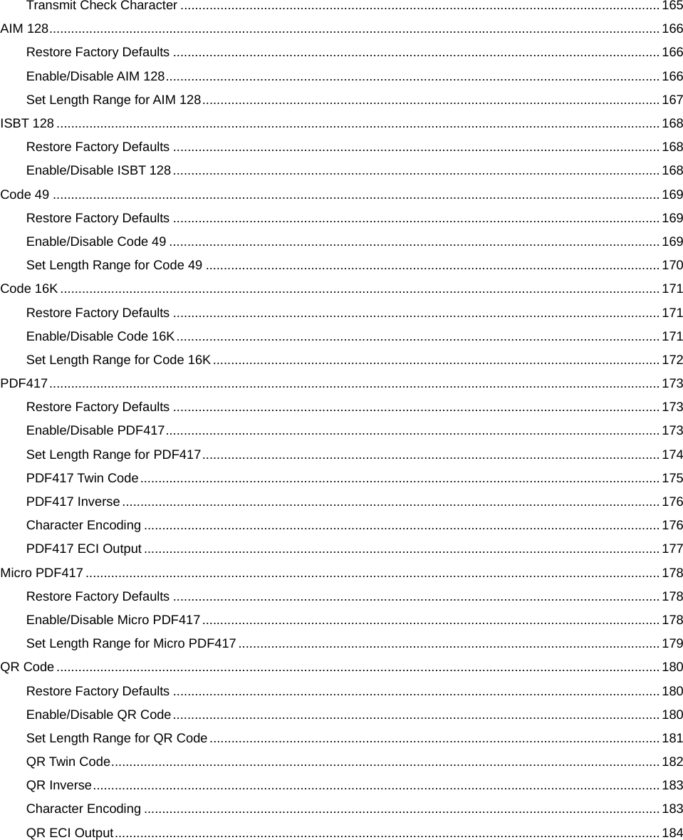
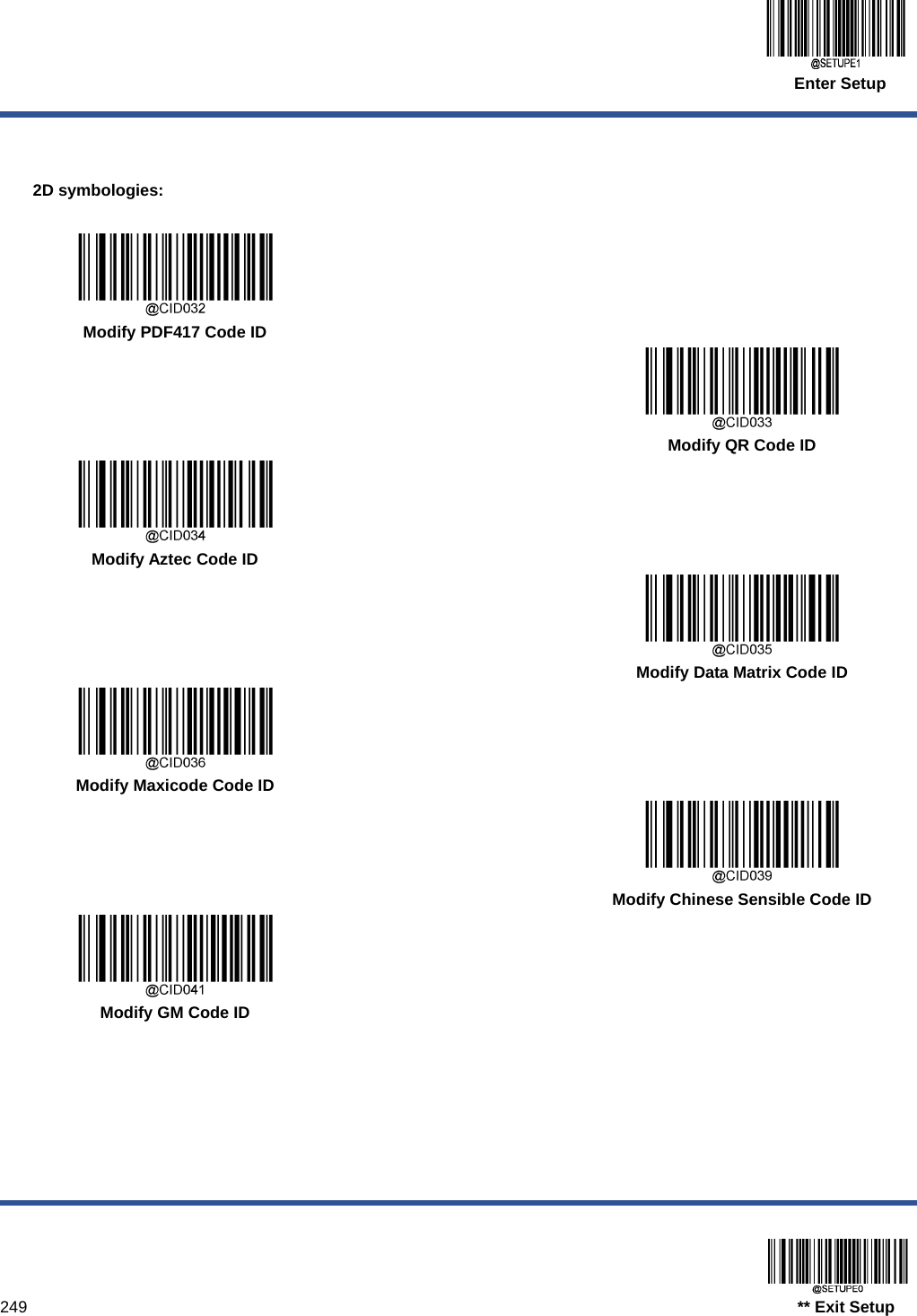
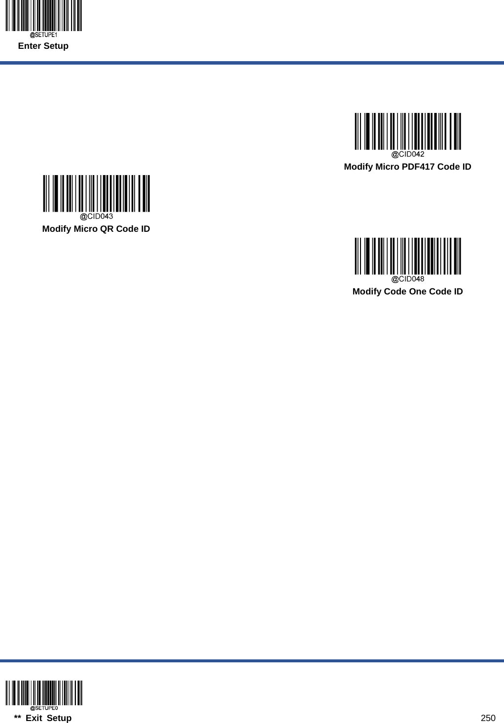
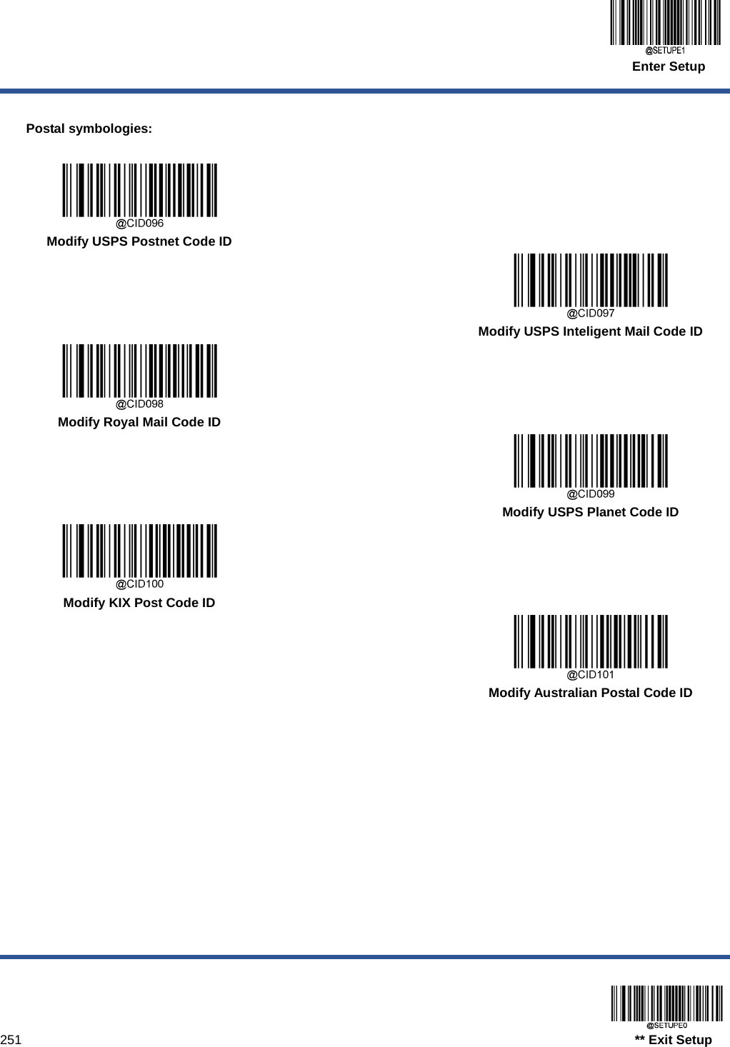
![Symbology AIM ID Possible AIM ID Modifiers (m) PDF417 ]Lm 0-2 QR Code ]Qm 0-6 Aztec ]zm 0-9, A-C Data Matrix ]dm 0-6 Maxicode ]Um 0-3 Chinese Sensible Code ]X0 GM ]gm (0~9) Micro PDF417 ]L0 Micro QR ]Q1 Code One ]X0 USPS Postnet ]X0 USPS Inteligent Mail ]X0 Royal Mail ]X0 USPS Planet ]X0 KIX Post ]X0 Australian Postal ]X0 Specific OCR-B ]o2 Passport OCR ]o2 Note: “m” represents the AIM modifier character. Refer to ISO/IEC 15424:2008 Information technology – Automatic identification and data capture techniques – Data Carrier Identifiers (including Symbology Identifiers) for AIM modifier character details.](https://usermanual.wiki/Fujian-Newland-Auto-ID-Tech/NLS-HR52/User-Guide-4129322-Page-295.png)
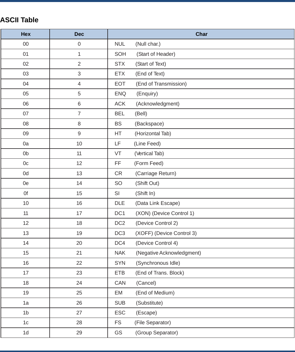
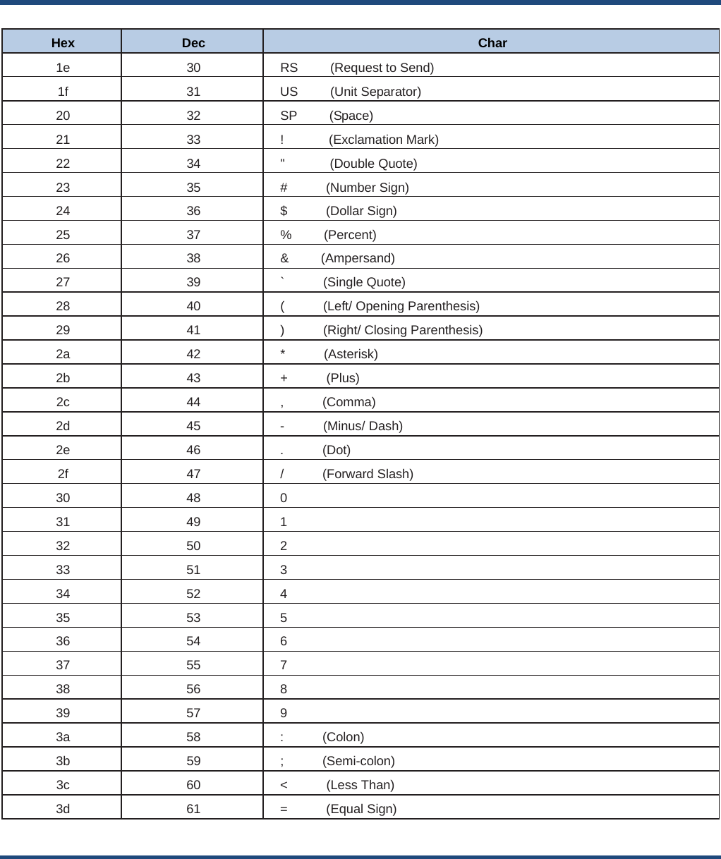
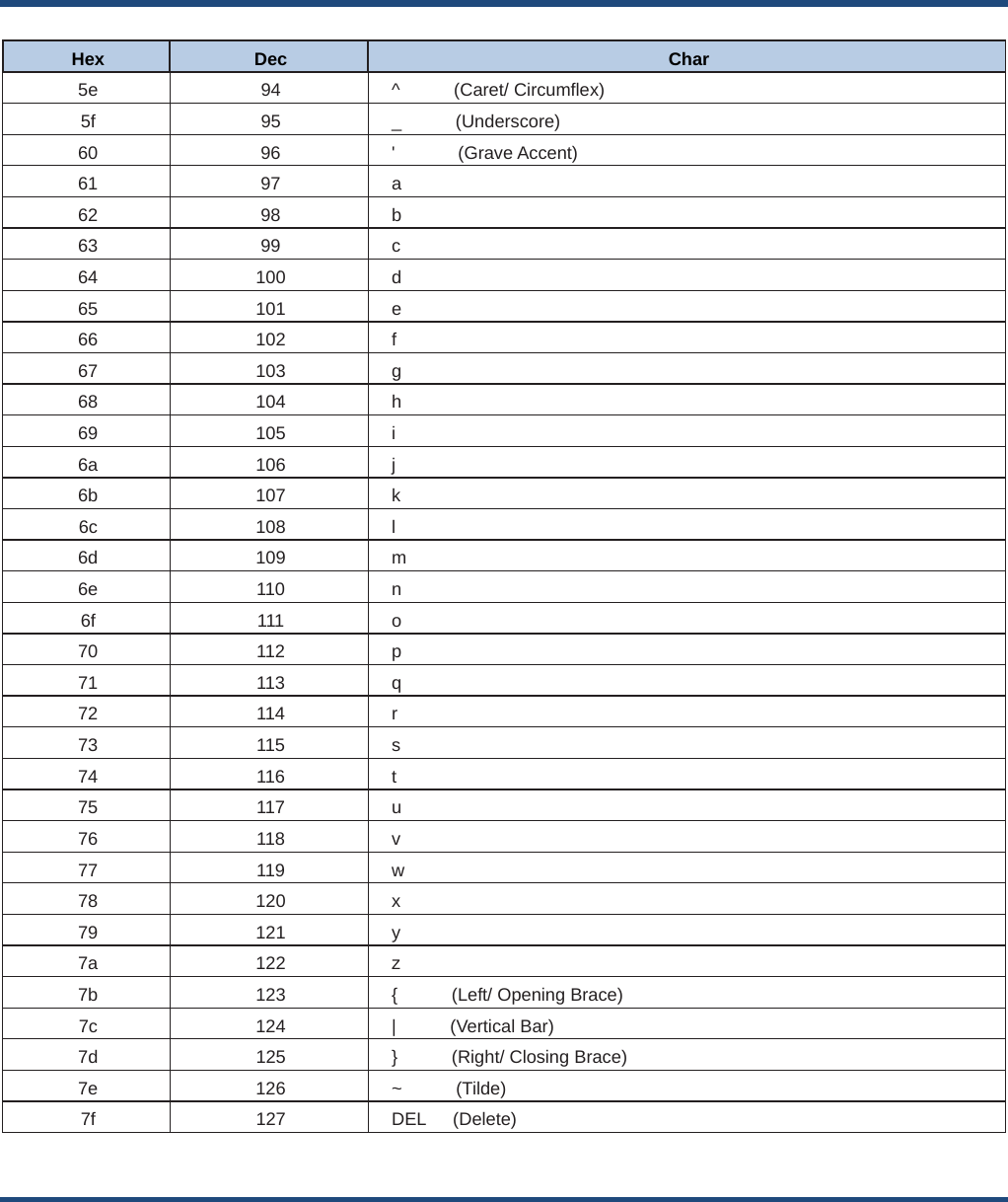
![Hex Dec Char 3e 62 > (Greater Than) 3f 63 ? (Question Mark) 40 64 @ (AT Symbol) 41 65 A 42 66 B 43 67 C 44 68 D 45 69 E 46 70 F 47 71 G 48 72 H 49 73 I 4a 74 J 4b 75 K 4c 76 L 4d 77 M 4e 78 N 4f 79 O 50 80 P 51 81 Q 52 82 R 53 83 S 54 84 T 55 85 U 56 86 V 57 87 W 58 88 X 59 89 Y 5a 90 Z 5b 91 [ (Left/ Opening Bracket) 5c 92 \ (Back Slash) 5d 93 ] (Right/ Closing Bracket)](https://usermanual.wiki/Fujian-Newland-Auto-ID-Tech/NLS-HR52/User-Guide-4129322-Page-302.png)