Fujitsu Client Computing EM7455D1 LTE Module User Manual Hardware Integration Guide
Fujitsu Limited LTE Module Hardware Integration Guide
Contents
- 1. User Manual
- 2. User Manual Hardware Integration Guide
- 3. Host User Manual
User Manual Hardware Integration Guide

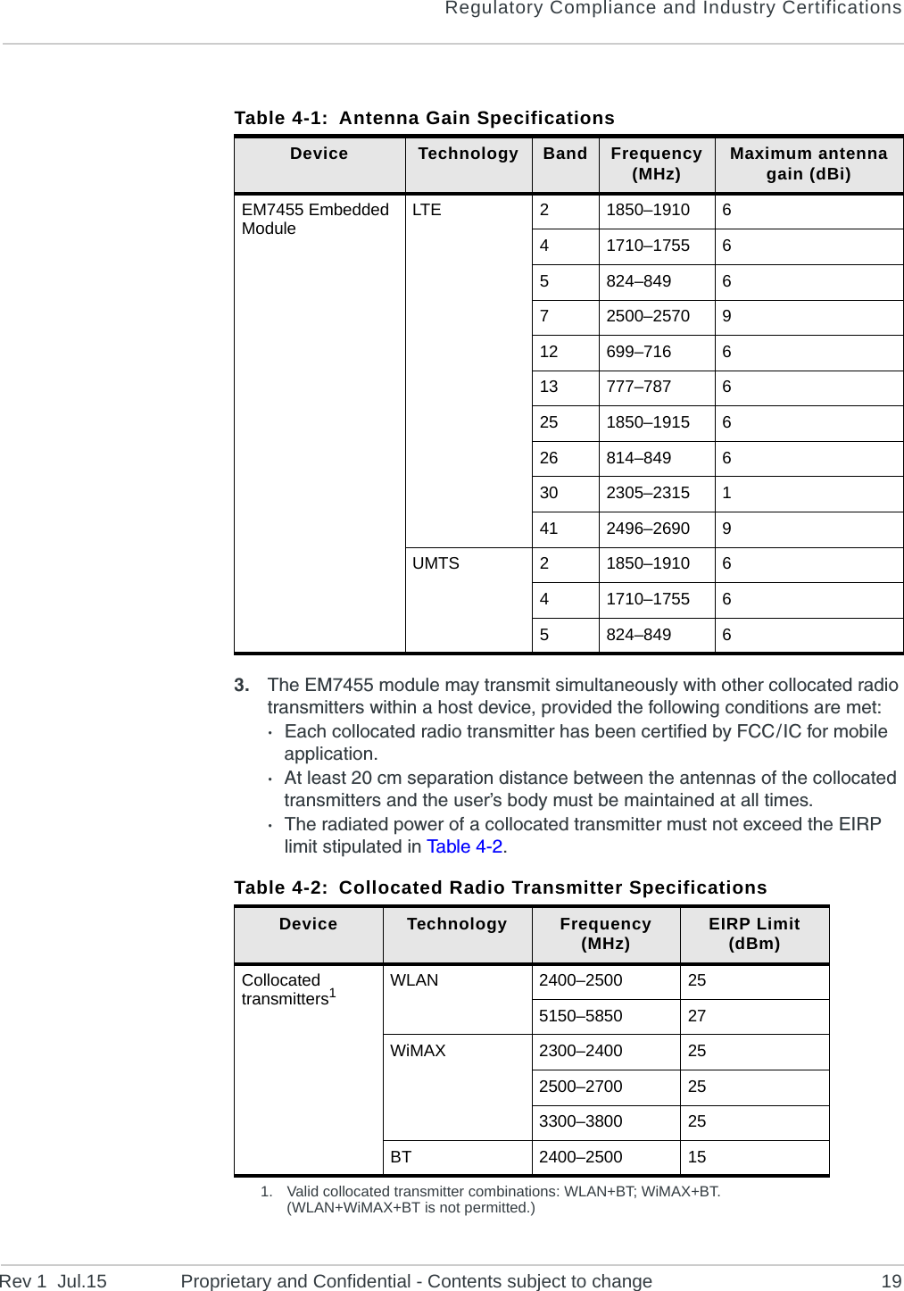
![Rev 1 Jul.15 Proprietary and Confidential - Contents subject to change 711: IntroductionThe Sierra Wireless EM7455 Embedded Module is an M.2 module that provides LTE, UMTS, and GNSS connectivity for notebook, ultrabook, tablet computers, and M2M applications over several radio frequency bands.AccessoriesA hardware development kit is available for AirPrime M.2 modules. The kit contains hardware components for evaluating and developing with the module, including:•Development board•Cables•Antennas•Other accessoriesFor over-the-air LTE testing, ensure that suitable antennas are used.Required ConnectorsTabl e 1-1 describes the connectors used to integrate the EM7455 Embedded Module into your host device.Table 1-1: Required Host–Module Connectors Connector type DescriptionRF cables •Mate with M.2-spec connectors•Three connector jacks (I-PEX 20448-001R-081 or equivalent)EDGE (67 pin) •Slot B compatible — Per the M.2 standard ([8] PCI Express NGFF (M.2) Electromechanical Specification Revision 1.0), a generic 75 pin position EDGE connector on the motherboard uses a mechanical key to mate with the 67 pin notched module connector.•Manufacturers include LOTES (part #APCI0018-P001A01), Kyocera, JAE, Tyco, and Longwell.SIM •Industry-standard connector.](https://usermanual.wiki/Fujitsu-Client-Computing/EM7455D1.User-Manual-Hardware-Integration-Guide/User-Guide-3235835-Page-7.png)

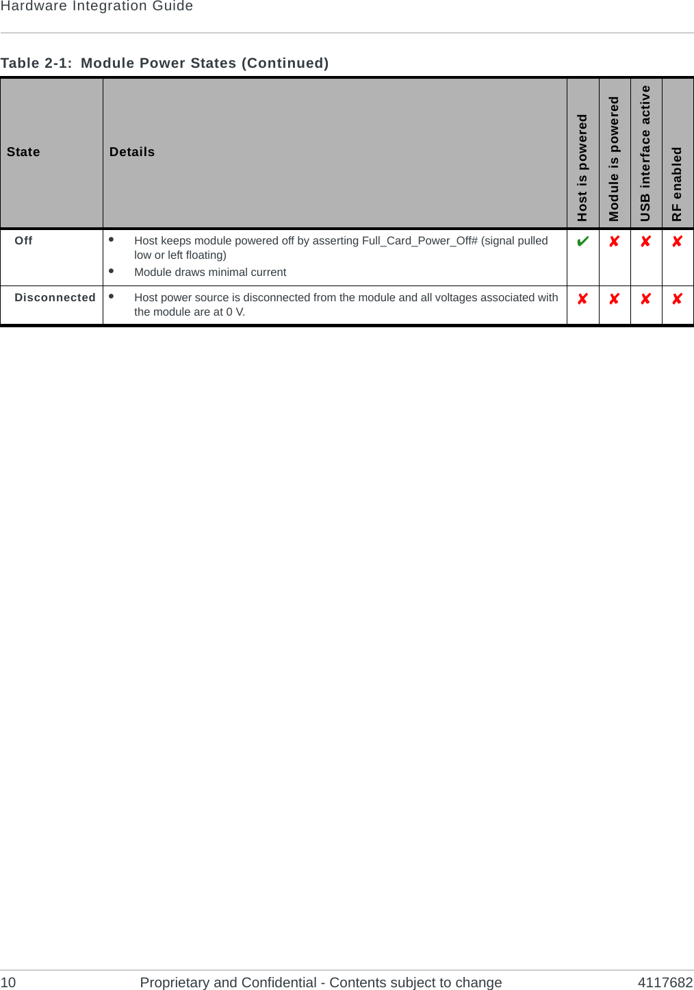
![Rev 1 Jul.15 Proprietary and Confidential - Contents subject to change 922: PowerPower SupplyThe host provides power to the EM7455 through multiple power and ground pins. The host must provide safe and continuous power (via battery or a regulated power supply) at all times; the module does not have an independent power supply, or protection circuits to guard against electrical issues.For detailed pinout and voltage / current requirements of this module, see the AirPrime EM7455 Product Technical Specification.Module Power StatesThe module has five power states, as described in Ta b l e 2-1. Table 2-1: Module Power States State DetailsHost is poweredModule is poweredUSB interface activeRF enabledNormal(Default state)•Module is active•Default state. Occurs when VCC is first applied, Full_Card_Power_Off# is deasserted (pulled high), and W_DISABLE1# is deasserted•Module is capable of placing / receiving calls, or establishing data connections on the wireless network•Current consumption is affected by several factors, including:•Radio band being used•Transmit power•Receive gain settings•Data rate Low power(‘Airplane mode’)•Module is active•Module enters this state:•Under host interface control:·Host issues AT+CFUN=0 ([1] AT Command Set for User Equipment (UE) (Release 6) (Doc# 3GPP TS 27.007))), or·Host asserts W_DISABLE1#, after AT!PCOFFEN=0 has been issued.•Automatically, when critical temperature or voltage trigger limits have been reached)) Sleep •Normal state of module between calls or data connections•Module cycles between wake (polling the network) and sleep, at network provider-determined interval. ](https://usermanual.wiki/Fujitsu-Client-Computing/EM7455D1.User-Manual-Hardware-Integration-Guide/User-Guide-3235835-Page-9.png)