Fujitsu Client Computing WB0003 LifeBook S Series with WLAN WLL3050 and Bluetooth User Manual Appendix P User Manual
Fujitsu Limited LifeBook S Series with WLAN WLL3050 and Bluetooth Appendix P User Manual
Contents
- 1. Users Manual Part 1
- 2. Users Manual Part 2
Users Manual Part 2
57
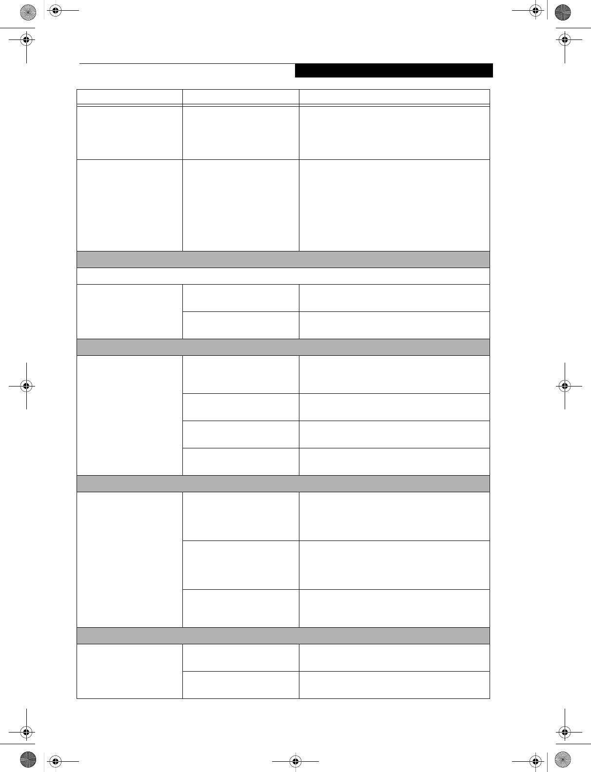
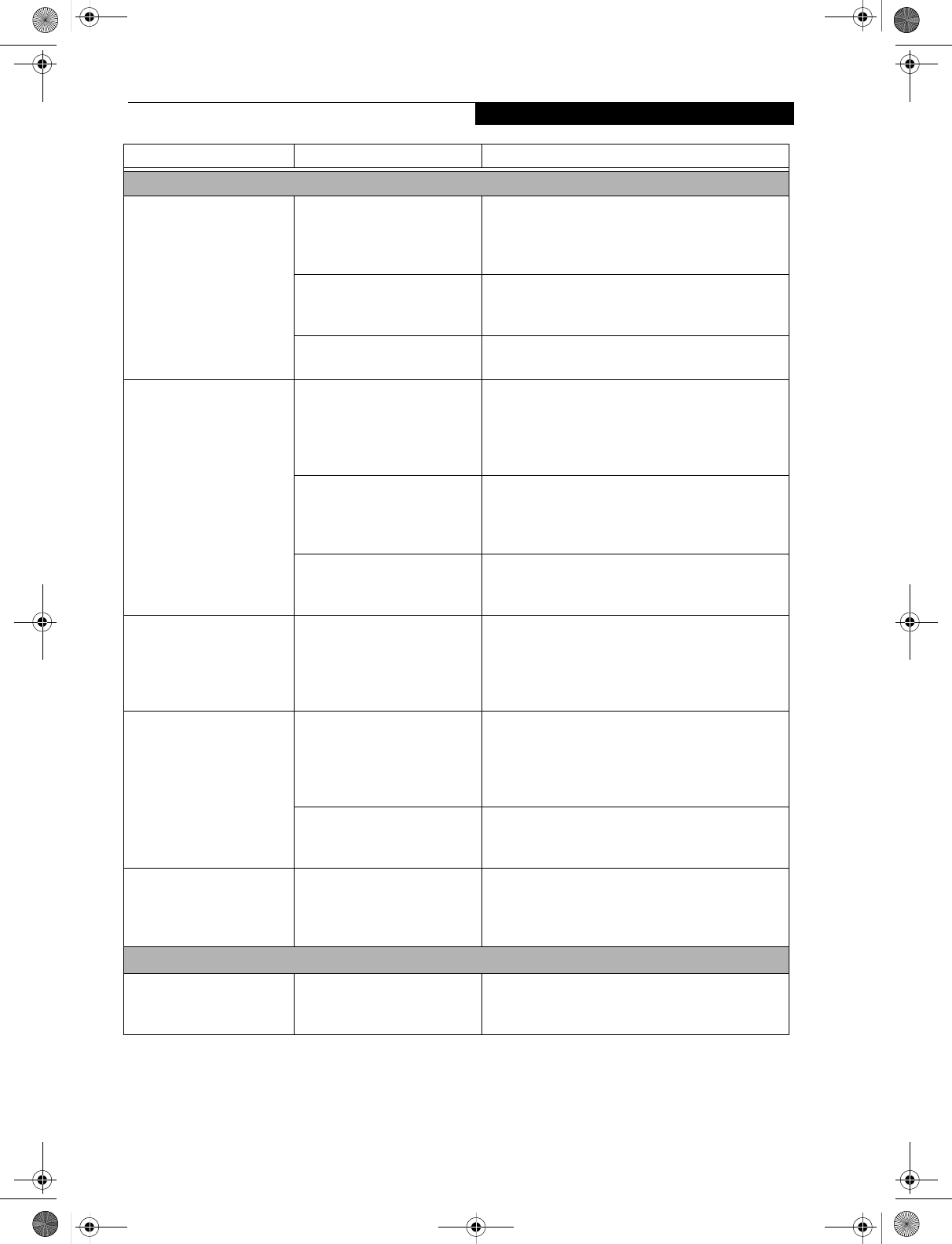
Troubleshooting
LifeBook notebook fails to
recognize DVD/CD-RW/
CD-ROM’s.
(continued)
DVD/CD-RW/CD-ROM is
dirty or defective.
Wipe DVD/CD-RW/CD-ROM with a non-abrasive
CD cleaning cloth and reinsert. It if still will not
work try another DVD/CD-RW/CD-ROM in
the drive.
The DVD/CD-RW/CD-
ROM Access indicator on
the Status Indicator Panel
blinks at regular intervals
when no DVD/CD-RW/
CD-ROM is in the tray or
the DVD/CD-RW/CD-
ROM drive is not installed.
The Windows DVD/CD-RW/
CD-ROM auto insertion func-
tion is active and is checking to
see if a DVD/CD-RW/CD-
ROM is ready to run.
This is normal. However, you may disable this
feature.
Port Replicator Problems
Note: Be sure to power down your LifeBook notebook before adding a printer to the Port Replicator parallel port.
LifeBook notebook does
not turn on when installed
in the optional Port
Replicator
Port Replicator AC adapter is
not plugged in.
Provide power to the Port Replicator.
Notebook is not properly
seated in the Port Replicator.
Remove and re-dock your LifeBook notebook.
Floppy Disk Drive Problems
You cannot access your
floppy disk.
You tried to write to a write
protected floppy disk.
Eject the floppy disk and set it to write enable.
(See Preparing a Disk for Use on page 42 for more
information)
Floppy disk is not
loaded correctly.
Eject floppy disk, check orientation and re-insert.
(See Ejecting a Disk on page 42 for more information)
The floppy disk drive may not
be properly installed.
Remove and re-install your floppy disk drive.
Security is set to protect access
to floppy disk data.
Verify your password and security settings.
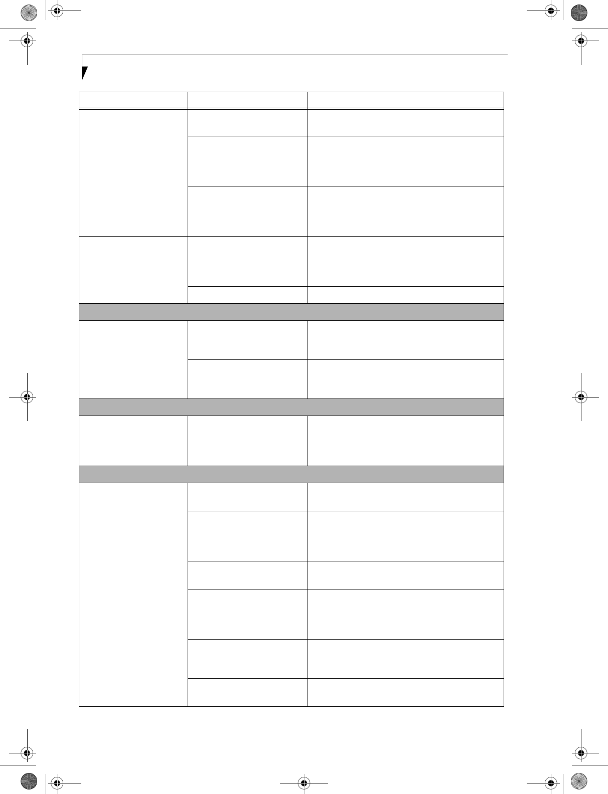
Hard Drive Problems
You cannot access your
hard drive.
The setup utility is incorrectly
set for your internal (Primary
Master) or optional second
hard drive (Primary Slave).
Revise BIOS settings to set both Primary Master
and Primary Slave correctly. (See BIOS Setup Utility
on page 29 for more information)
The wrong drive designator
was used by an application
when a bootable CD-ROM was
used to start the notebook.
Verify drive designator used by application is in
use by the operating system. When the operating
system is booted from a CD, drive designations
are automatically adjusted.
Security is set so your oper-
ating system cannot be started
without a password.
Verify your password and security settings.
Keyboard or Mouse Problems
The built-in keyboard does
not seem to work.
The notebook has gone into
Suspend mode.
Push the Power/Suspend/Resume button.
Your application has locked
out your keyboard.
Try to use your integrated pointing device to restart
your system.
Problem Possible Cause Possible Solutions
S Series.book Page 57 Thursday, February 12, 2004 4:15 PM
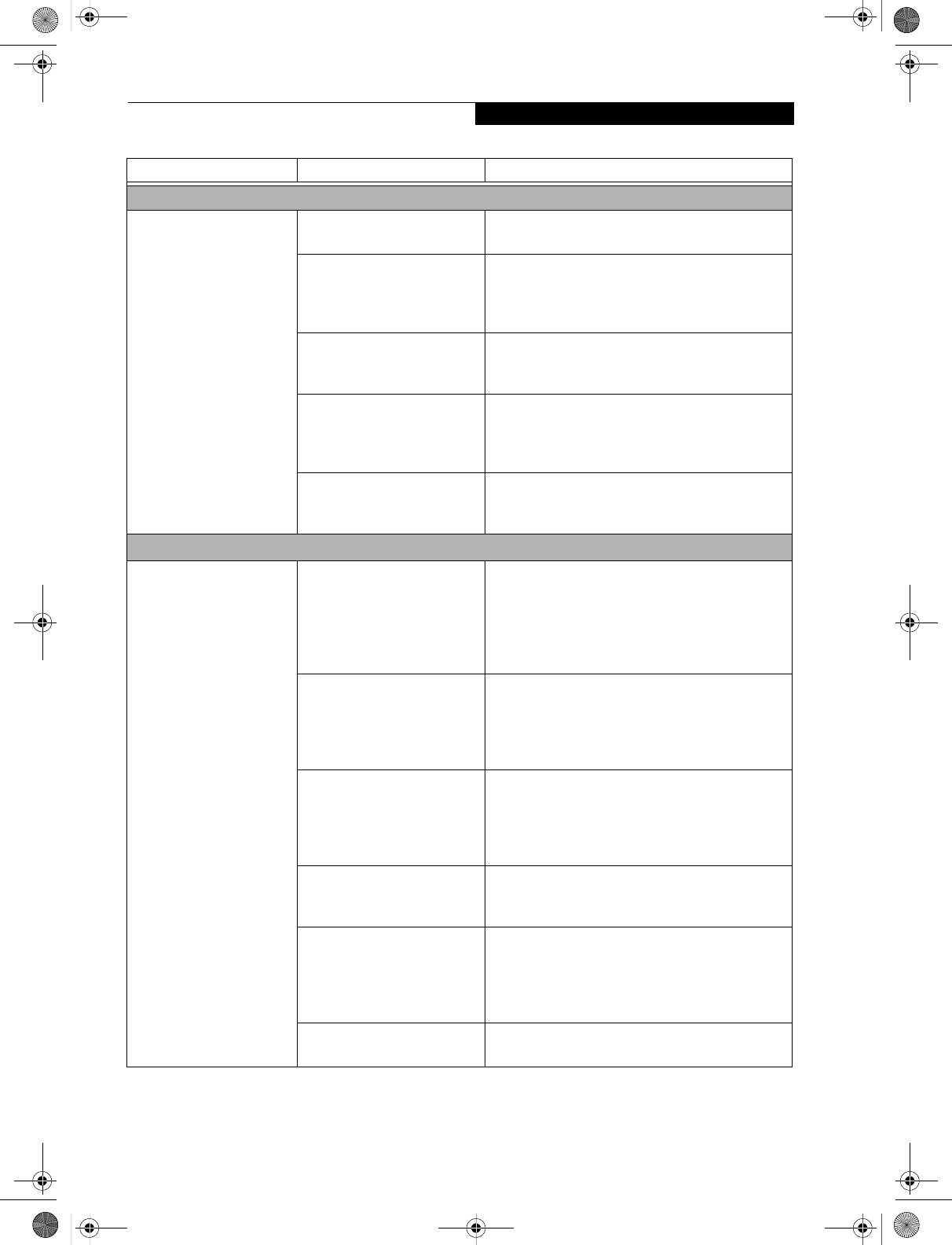
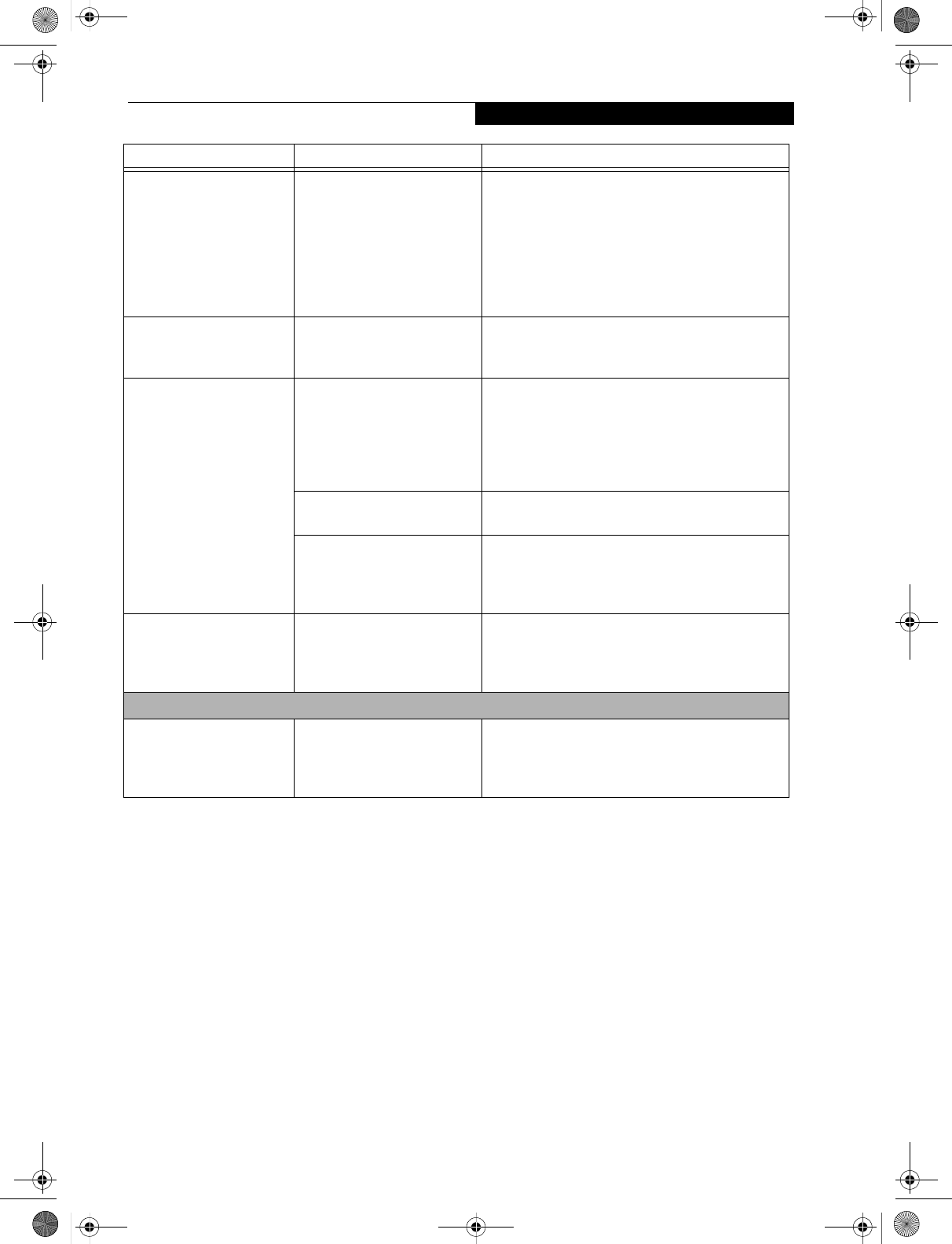
58
LifeBook S7000 Notebook
You have installed an
external keyboard or
mouse, and it does not
seem to work.
Your external device is not
properly installed.
Re-install your device. (See Device Ports on page 50
for more information)
Your operating system
software is not setup with the
correct software driver
for that device.
Check your device and operating system docu-
mentation and activate the proper driver.
Your mouse or keyboard is
connected to the wrong PS/2
port on the optional Port
Replicator.
Plug the mouse into the PS/2 Mouse port and
the external keyboard or numeric key pad into the
PS/2 Keyboard port. (See PS/2 Port on page 51 for
more information)
You have connected an
external keyboard or a
mouse and it seems to be
locking up the system.
Your operating system
software is not setup with
the correct software driver
for that device.
Check your device and operating system
documentation and activate the proper driver.
Your system has crashed. Try to restart your notebook. I
Memory Problems
Your Power On screen, or
Main menu of the BIOS
setup utility information,
does not show the correct
amount of installed
memory.
Your memory upgrade module
is not properly installed.
Remove and re-install your memory upgrade
module. (See Memory Upgrade Module on page 45
for more information)
You have a memory failure. Check for Power On Self Test (POST) messages.
(See Power On Self Test Messages on page 64 for more
information)
Modem Problems
Messages about modem
operation.
Messages about modem
operation are generated by
whichever modem application
is in use.
See your application software documentation for
additional information.
Parallel, Serial, and USB Device Problems
You have installed a parallel
port device, a serial port
device or a USB device.
Your LifeBook notebook
does not recognize the
device, or the device does
not seem to work properly.
The device is not
properly installed.
Remove and re-install the device. (See Device Ports
on page 50 for more information)
The device may have been
installed while an application
was running, so your notebook
is not aware of its installation.
Close the application and restart your notebook.
Your device may not have the
correct software driver active.
See your software documentation and activate the
correct driver.
You may have the wrong I/O
address selected for your
device.
See your device documentation and software docu-
mentation to determine the required I/O address.
Change the settings in the BIOS setup utility. (See
BIOS Setup Utility on page 29 for more information)
Your device and another device
are assigned the same I/O
address.
Check all I/O addresses located within the BIOS
setup utility and any other installed hardware or
software to make sure there are no duplications.
Parallel port is set to output
only.
Check parallel port setting in the BIOS and set to
bi-directional or ECP.
Problem Possible Cause Possible Solutions
S Series.book Page 58 Thursday, February 12, 2004 4:15 PM
59
Troubleshooting
PC Card Problems
A card inserted in the PC
Card slot does not work or
is locking up the system.
The card is not properly
installed.
Remove and re-install the card. (See PC Cards on
page 43 for more information)
The card may have been
installed while an application
was running, so your notebook
is not aware of its installation.
Close the application and restart your notebook.
Your software may not have
the correct software driver
active.
See your software documentation and activate the
correct driver.
You may have the wrong I/O
address selected for your PC
Card device.
See your PC Card documentation to determine
the required I/O address. Change the settings in
the BIOS. (See BIOS Setup Utility on page 29 for
more information)
Your PC Card device and
another device are assigned the
same I/O address.
Check all I/O addresses located within the BIOS
setup utility and any other installed hardware or
software to make sure there are no duplications.
Power Failures
You turn on your
LifeBook notebook and
nothing seems to happen.
The installed primary battery
is completely discharged, there
is no optional second battery
installed or there is no Power
adapter (AC or Auto/Airline)
installed.
Check the Status Indicator Panel to determine the
presence and condition of the batteries. (See Status
Indicator Panel on page 11 for more information)
Install a charged battery or a Power adapter.
The primary battery is
installed but is faulty.
Use the Status Indicator panel to verify the presence
and condition of the batteries. (See Status Indicator
Panel on page 11 for more information) If a battery is
indicating a short, remove that battery and operate
from another power source or replace that battery.
The battery or batteries are low. Check the Status Indicator Panel to determine the
presence and condition of the batteries. (See Status
Indicator Panel on page 11 for more information) Use
a Power adapter to operate until a battery is charged
or install a charged battery.
The power adapter (AC or
auto/airline) is not plugged
in properly.
Verify that your adapter is connected correctly. (See
Power Sources on page 27 for more information)
The Power adapter (AC or
auto/airline) has no power
from the AC outlet, airplane
seat jack, or the car’s cigarette
lighter.
Move the AC cord to a different outlet, check for
a line switch or tripped circuit breaker for the AC
outlet. If you are using an auto/airline adapter in
a car make sure the ignition switch is in the On or
Accessories position.
The Power adapter (AC or
auto/airline) is faulty.
Try a different Power adapter or install a charged
optional second battery.
Problem Possible Cause Possible Solutions
S Series.book Page 59 Thursday, February 12, 2004 4:15 PM
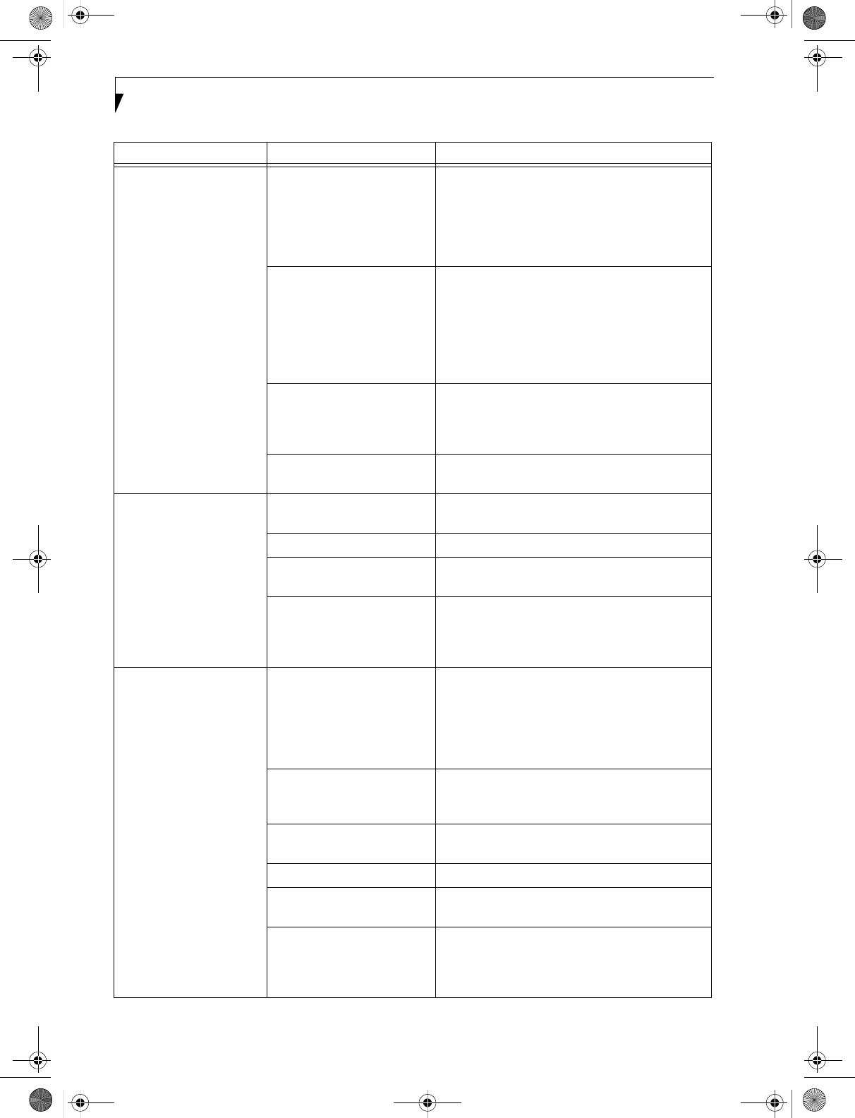
60
LifeBook S7000 Notebook
Your LifeBook notebook
turns off all by itself.
The power management
parameters are set for auto
timeouts which are too short
for your operating needs.
Press any button on the keyboard, or move the
mouse to restore operation. If that fails, push the
Power/Suspend/Resume button. Check your power
management settings, or close your applications and
go to the Power Savings menu of the setup utility to
adjust the timeout values to better suit your needs.
You are operating on battery
power only and have ignored a
low battery alarm until the
batteries are all at the dead
battery state and your machine
has gone into Dead Battery
Suspend mode.
Install a power adapter and then push the Power/
Suspend/Resume button. (See Power Sources on
page 27 for more information)
You have a battery failure. Verify the condition of the batteries using the
Status Indicator panel, and replace or remove
any batteries that are shorted. (See Status Indicator
Panel on page 11 for more information)
Your power adapter has failed
or lost its power source.
Make sure the adapter is plugged in and the outlet
has power.
Your LifeBook notebook
will not work on battery
alone.
The installed batteries
are dead.
Replace the battery with a charged one or install
a Power adapter.
No batteries are installed. Install a charged battery.
The batteries are improperly
installed.
Verify that the batteries are properly connected
by re-installing them.
Your installed batteries
are faulty.
Verify the condition of the batteries using the
Status Indicator panel and replace or remove
any batteries that are shorted. (See Status Indicator
Panel on page 11 for more information)
The batteries seem to
discharge too quickly.
You are running an application
that uses a great deal of power
due to frequent hard drive
access or DVD/CD-ROM
access, use of a modem card
or a LAN PC card.
Use both the primary battery and an optional
second battery and/or use a power adapter for this
application when at all possible.
The power savings features
may be disabled.
Check the power management and/or setup utility
settings in the Power Savings menu and adjust
according to your operating needs.
The brightness is turned all
the way up.
Turn down the brightness adjustment. The higher
the brightness the more power your display uses.
The batteries are very old. Replace the batteries.
The batteries have been
exposed to high temperatures.
Replace the batteries.
The batteries are too hot
or too cold.
Restore the notebook to normal operating tempera-
ture. The Charging icon on the Status Indicator
panel will flash when the battery is outside its
operating range.
Problem Possible Cause Possible Solutions
S Series.book Page 60 Thursday, February 12, 2004 4:15 PM
61
Troubleshooting
Shutdown and Startup Problems
The Suspend/Resume
button does not work.
The Suspend/Resume button
is disabled from the Advanced
submenu of the Power menu
of the setup utility.
Enable the button from the setup utility.
You did not hold the button
in long enough.
Hold the button longer. This may need to be a few
seconds if your application is preventing the CPU
from checking for button pushes.
There may be a conflict with
the application software.
Close all applications and try the button again.
The system powers up, and
displays power on informa-
tion, but fails to load the
operating system.
The boot sequence settings
of the setup utility are not
compatible with your
configuration.
Set the operating source by pressing the [ESC] key
while the Fujitsu logo is on screen or use the [F2]
key and enter the setup utility and adjust the source
settings from the Boot menu. (See BIOS Setup
Utility on page 29 for more information)
You have a secured system
requiring a password to load
your operating system.
Make sure you have the right password. Enter the
setup utility and verify the Security settings and
modify them as accordingly. (See BIOS Setup Utility
on page 29 for more information)
Internal hard drive was
not detected.
Use the BIOS setup utility or Primary Master
submenu, located within the Main menu, to try to
auto detect the internal hard drive.
An error message is
displayed on the screen
during the notebook
(boot) sequence.
Power On Self Test (POST) has
detected a problem.
See the Power On Self Test (POST) messages to
determine the meaning and severity of the problem.
Not all messages are errors; some are simply status
indicators. (See Power On Self Test Messages on
page 64 for more information)
Your notebook appears to
change setup parameters
when you start it.
BIOS setup changes were not
saved when you made them
and exited the BIOS setup
utility returning it to
previous settings.
Make sure you select Save Changes And Exit when
exiting the BIOS setup utility.
The BIOS CMOS hold-up
battery has failed.
Contact your support representative for repairs.
This is not a user serviceable part but has a normal
life of 3 to 5 years.
Your system display won’t
turn on when the system is
turned on or when the
system has resumed.
The system may be password-
protected.
Check the status indicator panel to verify that the
Security icon is blinking. If it is blinking, enter your
password.
Video Problems
The built-in display is
blank when you turn on
your LifeBook notebook.
Something is pushing on the
Closed Cover switch.
Clear the Closed Cover switch. (See figure 2-4 on
page 6 for location)
Problem Possible Cause Possible Solutions
S Series.book Page 61 Thursday, February 12, 2004 4:15 PM

62
LifeBook S7000 Notebook
The built-in display is
blank when you turn on
your LifeBook notebook.
(continued)
The notebook is set for an
external monitor only.
Pressing [F10] while holding down the [Fn] key
allows you to change your selection of where to
send your display video. Each time you press the
combination of keys you will step to the next
choice. The choices, in order are: built-in display
only, external monitor only, both built-in display
and external monitor.
The angle of the display and
the brightness settings are not
adequate for your lighting
conditions.
Move the display and the brightness control until
you have adequate visibility.
The power management time-
outs may be set for very short
intervals and you failed to
notice the display come on
and go off again.
Press any button the keyboard, or move the mouse
to restore operation. If that fails, push the Power/
Suspend/Resume button. (The display may be shut
off by Standy mode, Auto Suspend or Video
Timeout)
The LifeBook notebook
turned on with a series of
beeps and your built-in
display is blank.
Power On Self Test (POST)
has detected a failure which
does not allow the display
to operate.
Contact your support representative.
The display goes blank by
itself after you have been
using it.
The notebook has gone into
Video timeout, Standby mode,
Suspend mode or Save-to-Disk
mode because you have not
used it for a period of time.
Press any button on the keyboard, or move the
mouse to restore operation. If that fails, push the
Power/Suspend/Resume button. Check your power
management settings, or close your applications
and go to the Power Savings menu of the setup
utility to adjust the timeout values to better suit
your operation needs. (See BIOS Setup Utility on
page 29 for more information)
The power management time-
outs may be set for very short
intervals and you failed to
notice the display come on
and go off again.
Press any button on the keyboard, or move the mouse
to restore operation. If that fails, push the Power/
Suspend/Resume button. (The display may be shut
off by Standby Mode, Auto Suspend or Video
Timeout)
Something is pushing on the
Closed Cover switch.
Check the Closed Cover switch. (See figure 2-4 on
page 6 for location)
Your system display won’t
turn on when the system is
turned on or when the
system has resumed.
The system may be password-
protected.
Check the status indicator panel to verify that the
Security icon is blinking. If it is blinking, enter your
password.
The Built-in Display does
not close.
A foreign object, such as a
paper clip, is stuck between the
display and the keyboard.
Remove all foreign objects from the keyboard.
The Built-in Display has
bright or dark spots.
If the spots are very tiny and
few in number, this is normal
for a large LCD display.
This is normal; do nothing.
If the spots are numerous or
large enough to interfere with
your operation needs.
Display is faulty; contact your support representative.
Problem Possible Cause Possible Solutions
S Series.book Page 62 Thursday, February 12, 2004 4:15 PM
63
Troubleshooting
The application display
uses only a portion of your
screen and is surrounded
by a dark frame.
You are running an application
that does not support 800 x
600/1024 x 768 pixel resolution
display and display compres-
sion is enabled.
Display compression gives a clearer but smaller
display for applications that do not support 800 x
600/1024 x 768 pixel resolution. You can fill the
screen but have less resolution by changing your
display compression setting, (See the Video Features
submenu, located within the Advanced menu of the
BIOS. (See BIOS Setup Utility on page 29 for more
information)
The Display is dark when
on battery power.
The Power Management utility
default is set on low brightness
to conserve power.
Press [Fn] + [F7] to increase brightness or double-
click on the battery gauge and adjust Power Control
under battery settings.
You have connected an
external monitor and
it does not display
any information.
Your BIOS setup is not set to
enable your external monitor.
Try toggling the video destination by pressing [Fn]
and [F10] together, or check your BIOS setup and
enable your external monitor. (See the Video Features
submenu, located within the Advanced Menu of the
BIOS. (See BIOS Setup Utility on page 29 for more
information)
Your external monitor is not
properly installed.
Reinstall your device. (See External Monitor Port on
page 52 for more information)
Your operating system soft-
ware is not setup with the
correct software driver for
that device.
Check your device and operating system
documentation and activate the proper driver.
You have connected an
external monitor and it
does not come on.
Your external monitor is not
compatible with your LifeBook
notebook.
See your monitor documentation and the
External Monitor Support portions of the
Specifications section. (See Specifications on page 77
for more information)
Miscellaneous Problems
An error message is
displayed on the screen
during the operation of
an application.
Application software often
has its own set of error
message displays.
See your application manual and help displays
screens for more information. Not all messages are
errors some may simply be status.
Problem Possible Cause Possible Solutions
S Series.book Page 63 Thursday, February 12, 2004 4:15 PM

64
LifeBook S7000 Notebook
POWER ON SELF TEST MESSAGES
The following is an alphabetic list of error-and-status
messages that Phoenix BIOS and/or your operating
system can generate and an explanation of each message.
Error messages are marked with an *. If an error message
is displayed that is not in this list, write it down and
check your operating system documentation both on
screen and in the manual. If you can find no reference
to the message and its meaning is not clear, contact
your support representative for assistance.
nnnn Cache SRAM Passed
Where nnnn is the amount of system cache in kilobytes
success-fully tested by the Power On Self Test. (This can
only appear if you have an SRAM PC Card installed.)
*Diskette drive A error or Diskette drive B error
Drive A: or B: is present but fails the BIOS Power On Self
Test diskette tests. Check to see that the drive is defined
with the proper diskette type in the Setup Utility, (See
BIOS Setup Utility on page 29 for more information) and
that the diskette drive is installed correctly. If the disk
drive is properly defined and installed, avoid using it and
contact your support representative.
*Extended RAM Failed at offset: nnnn
Extended memory not working or not configured prop-
erly. If you have an installed memory upgrade module,
verify that the module is properly installed. If it is prop-
erly installed, you may want to check your Windows
Setup to be sure it is not using unavailable memory
until you can contact your support representative.
nnnn Extended RAM Passed
Where nnnn is the amount of memory in kilobytes
successfully tested.
*Failing Bits: nnnn The hex number nnnn
This is a map of the bits at the memory address (in
System, Extended, or Shadow memory) which failed the
memory test. Each 1 (one) in the map indicates a failed
bit. This is a serious fault that may cause you to lose data
if you continue. Contact your support representative.
*Fixed Disk x Failure or Fixed Disk Controller
Failure (where x = 1-4)
The fixed disk is not working or not configured properly.
This may mean that the hard drive type identified in
your setup utility does not agree with the type detected
by the Power On Self Test. Run the setup utility to check
for the hard drive type settings and correct them if
necessary. If the settings are OK and the message appears
when you restart the system, there may be a serious fault
which might cause you to lose data if you continue.
Contact your support representative.
*Incorrect Drive A type – run SETUP
Type of floppy drive A: not correctly identified in Setup.
This means that the floppy disk drive type identified in
your setup utility does not agree with the type detected
by the Power On Self Test. Run the setup utility to
correct the inconsistency.
*Incorrect Drive B type – run SETUP
Type of floppy drive B: not correctly identified in Setup.
This means that the floppy disk drive type identified in
your setup utility does not agree with the type detected
by the Power On Self Test. Run the setup utility to
correct the inconsistency.
*Invalid NVRAM media type
Problem with NVRAM access. In the unlikely case that
you see this message you may have some display prob-
lems. You can continue operating but should contact
your support representative for more information.
*Keyboard controller error
The keyboard controller test failed. You may have to
replace your keyboard or keyboard controller but may
be able to use an external keyboard until then. Contact
your support representative.
*Keyboard error
Keyboard not working. You may have to replace your
keyboard or keyboard controller but may be able to
use an external keyboard until then. Contact your
support representative.
*Keyboard error nn
BIOS discovered a stuck key and displays the scan code
for the stuck key. You may have to replace your keyboard
but may be able to use an external keyboard until then.
Contact your support representative.
*Monitor type does not match CMOS – Run SETUP
Monitor type not correctly identified in Setup. This error
probably means your BIOS is corrupted, run the setup
utility and set all settings to the default conditions. If you
still get this error, contact your support representative.
*Operating system not found
Operating system cannot be located on either drive A: or
drive C: Enter the setup utility and see if both the fixed
disk, and drive A: are properly identified and that the
boot sequence is set correctly. Unless you have changed
your installation greatly, the operating system should be
on drive C:. If the setup utility is correctly set, your hard
drive may be corrupted.
*Parity Check 1 nnnn
Parity error found in the system bus. BIOS attempts
to locate the address and display it on the screen. If it
cannot locate the address, it displays ????. This is a
potentially data destroying failure. Contact your
support representative.
S Series.book Page 64 Thursday, February 12, 2004 4:15 PM

65
Troubleshooting
*Parity Check 2 nnnn
Parity error found in the I/O bus. BIOS attempts to
locate the address and display it on the screen. If it
cannot locate the address, it displays ????. This is a
potentially data-destroying failure. Contact your
support representative.
*Press <F1> to resume, <F2> to SETUP
Displayed after any recoverable error message. Press
the [F1] key to continue the boot process or the [F2]
key to enter Setup and change any settings.
*Previous boot incomplete –
Default configuration used
Previous Power On Self Test did not complete success-
fully. The Power On Self Test will load default values and
offer to run Setup. If the previous failure was caused by
incorrect values and they are not corrected, the next
boot will likely fail also. If using the default settings does
not allow you to complete a successful boot sequence,
you should turn off the power and contact your support
representative.
*Real time clock error
Real-time clock fails BIOS test. May require board repair.
Contact your support representative.
*Shadow RAM Failed at offset: nnnn
Shadow RAM failed at offset nnnn of the 64k block at
which the error was detected. You are risking data corrup-
tion if you continue. Contact your support representative.
nnnn Shadow RAM Passed
Where nnnn is the amount of shadow RAM in kilobytes
successfully tested.
*System battery is dead – Replace and run SETUP
The BIOS CMOS RAM memory hold up battery is dead.
This is part of your BIOS and is a board mounted
battery which requires a support representative to
change. You can continue operating but you will have to
use setup utility default values or reconfigure your setup
utility every time you turn off your notebook. This
battery has an expected life of 2 to 3 years.
System BIOS shadowed
System BIOS copied to shadow RAM.
*System CMOS checksum bad – run SETUP
BIOS CMOS RAM has been corrupted or modified
incorrectly, perhaps by an application program that
changes data stored in BIOS memory. Run Setup and
reconfigure the system.
*System RAM Failed at offset: nnnn
System memory failed at offset nnnn of in the 64k block
at which the error was detected. This means that there is
a fault in your built-in memory. If you continue to
operate, you risk corrupting your data. Contact your
support representative for repairs.
nnnn System RAM Passed
Where nnnn is the amount of system memory in
kilobytes successfully tested.
*System timer error
The timer test failed. The main clock that operates the
computer is faulty. Requires repair of system board.
Contact your support representative for repairs.
UMB upper limit segment address: nnnn
Displays the address of the upper limit of Upper
Memory Blocks, indicating released segments of the
BIOS memory which may be reclaimed by a virtual
memory manager.
Video BIOS shadowed
Video BIOS successfully copied to shadow RAM.
EMERGENCY MEDIA PLAYER
DRIVE TRAY RELEASE
If for some reason the eject button fails, you can open
the DVD/CD-ROM tray with a paper clip or similar tool
inserted into the eject hole in the far right side of the
front of the tray. Straighten one side of a paper clip
and push it gently into the hole. The tray will pop out
a short distance.
MODEM RESULT CODES
The operating system and application software that is
factory installed detects the modem characteristics and
provides the necessary command strings to operate the
modem. The internal modem operation is controlled by
generic AT commands from the operating system and
application software. The standard long form result
codes may, in some cases, be displayed on your screen to
keep you informed of the actions of your modem. The
operating system and application software may suppress
display of the result codes.
Examples of result codes are:
■OK
■NO CARRIER
■NO DIALTONE
■CONNECT 53000 (Connection complete
at 53,000 bps.)
■ERROR
■FAX
■RING (This means an incoming call.)
■BUSY
■NO ANSWER
When using the internal modem with applications
that are not factory installed refer to the
application documentation.
S Series.book Page 65 Thursday, February 12, 2004 4:15 PM
66
LifeBook S7000 Notebook
RESTORING YOUR
PRE-INSTALLED SOFTWARE
The Drivers and Applications Restore (DAR) CD
contains:
■Sets of device drivers and Fujitsu utilities (in specific
directories) that are unique to your LifeBook note-
book configuration for use as documented below.
■A link to the Drive Image Special Edition (DISE)
utility on your hard disk drive.
■Read-me files that provide additional use information
for items on this CD-ROM.
DRIVE IMAGE SPECIAL EDITION (DISE)
PowerQuest Drive Image Special Edition (DISE)
provides a way to restore your computer if you experi-
ence a hard disk crash or other system failure. Fujitsu has
used DISE to create an image of everything installed on
the computer at the time you purchased it. The image is
saved on a separate partition on the hard disk. You can
use DISE to restore the factory image and return your
computer to the state in which it was shipped from
Fujitsu.
Although it is not necessary, you can use DISE to store
additional image files that you create. For example, if
you install several applications and save data files on
your hard disk, you can create a new image file that
includes them and then save that image file on the hard
disk. Then, in the event of a hard disk failure, you can
restore the image that includes the applications and data
files you use.
Creating a Backup Image
You can create a backup image of your C:\ drive at any
time. The C:\ partition must be a FAT, FAT32, or NTFS
partition, and it must be directly before the backup
partition on your hard disk.
There are two ways to implement the DISE utility: When
booting up the system, or from the desktop.
Creating a backup image when booting up
Before creating a backup image at boot-up, you must
first change the boot-up priority in the BIOS so that the
system will go to the CD drive first, rather than trying to
boot-up from the hard drive or an external floppy disk
drive.
To change the boot-up priority:
1. Start your system and press the [F2] key when the
Fujitsu logo appears. You will enter the BIOS Setup
Utility.
2. Using the arrow keys, go to the Boot menu.
3. Arrow down to the Boot Device Priority submenu
and press [Enter].
4. Arrow down to the CD-ROM drive in the list, and
press the space bar (or the + key) to move the CD-
ROM drive to the top of the list. (The system
attempts to boot from the devices in the order in
which they are listed.)
5. Press [F10], then click on [Yes] to exit the BIOS
Setup Utility and return to the boot process.
After you have changed the boot priority, you can create
a backup image when you are booting up:
1. Install the DAR CD in the drive prior to booting up.
When bootup begins, a message will appear
informing you that continuing to boot from the CD
will overwrite all information on the hard drive,
including saved files, and restore the hard drive to its
factory configuration.
2. When you are asked if you want to restore the
factory image, click [Y]es.
Creating a backup image from the desktop
To create a backup image from the desktop, select Drive
Image SE from the Program list. You will initially be
prompted to create a backup diskette. It is not necessary
If your system was delivered with
Windows 2000 as the operating system,
the Windows 2000 image is on the D:
partition, but the Restore Disc contains
Windows XP. If you decide to restore your
system from the Restore Disc, you will
overwrite Windows 2000 with the
Windows XP operating system.
If the DAR CD is in the drive when you
boot up the system, a message will appear
informing you that continuing to boot
from the CD will overwrite all information
on the hard drive, including saved files,
and restore the hard drive to its factory
configuration. If you wish to install drivers
or applications only from the CD, remove
the disk from the drive, reboot the system,
and insert the CD after Windows has
started.
If you have access to the internet, visit the
Fujitsu Support web site at us.fujitsu.com/
computers to check for the most current
information, drivers and hints on how to
perform recovery and system updates.
Using the DISE feature will reduce the
amount of usable disk space on your hard
disk drive.
S Series.book Page 66 Thursday, February 12, 2004 4:15 PM

67
Troubleshooting
to create the backup diskette, since the DAR CD
performs the same function.
1. At the Drive Image Special Edition main screen,
click Options> Create New Backup. DISE displays a
warning that it must go to DOS to create the image.
3. Click Yes.
DISE creates an image file in the backup partition. If
you created a backup image previously, the new
image overwrites the old one.
Enlarging the Backup Partition
If there is not enough unused space in the backup parti-
tion on your hard disk, DISE will resize the partition.
DISE will display the minimum, maximum, and recom-
mended sizes for the backup partition. You choose the
size you want.
DISE takes the space from the FAT, FAT32, or NTFS
partition that you are backing up. If there is not enough
unused space in that partition to take, you will not be
able to resize the backup partition and create an image
file. You can delete files from the FAT, FAT32, or NTFS
partition to create more unused space on the hard disk.
Restoring a Backup Image
You can restore either a factory image or a backup image
you created. Be aware that restoring a backup image will
replace the contents of the C:\ partition with the image
you restore.
1. Disable virus protection software. If virus protection
software is enabled, DISE will hang.
2. From the DISE main window, click Options >
Restore Backup to restore an image you created, or
click Options > Restore Factory Backup to restore
the factory image.
DISE shuts down to DOS and restores the image file.
Re-Installing Individual Drivers and Applications
The Drivers and Application CD can be used to selec-
tively re-install drivers and/or applications that may have
been un-installed or corrupted.
To re-install drivers and/or applications:
1. Boot up the system and insert the DAR CD after
Windows has started. The LifeBook Easy Installation
screen appears.
2. Select the drivers and applications you want to
install from the list that is displayed.
3. Click [Start]. Follow the prompts that appear to
complete installation of the selected drivers and/or
applications.
AUTOMATICALLY DOWNLOADING
DRIVER UPDATES
Your system has a convenient tool called the Fujitsu
Driver Update (FDU) utility. With FDU, you can choose
to automatically or manually go to the Fujitsu site to
check for new updates for your system.
The FDU icon should appear in the system tray at the
bottom right of your screen (roll the cursor over the
icons to find the correct one). If the FDU icon does not
appear in the system tray, it can be started by going to
[Start] -> All Programs, and clicking on Fujitsu Driver
Update; this will create the icon automatically.
To invoke the FDU menu, you can either right-click on
the FDU icon or hold the pen on the icon for a couple of
seconds until the menu appears. The menu contains the
following items:
■Check for updates now
Allows for manual driver update search. The first
time it is used, you are prompted to agree to a user
agreement. After clicking on the icon, the FDU auto-
matically connects with the Fujitsu site to check for
updates and downloads them. While downloading,
the icon has a red bar through it, indicating that it
cannot be used while the download is in process.
When the update is complete, a message appears
informing you of the fact.
■Enable Automatic Update Notifications
Automatically searches for new updates on a regular
basis (approximately every 3 days).
■Show update history
Brings up a screen that displays a history of updates
that have been made via the FDU.
■About Fujitsu Driver Update
Displays the FDU version number and copyright
information
■Fujitsu Driver Update Readme
Displays the FDU readme.
S Series.book Page 67 Thursday, February 12, 2004 4:15 PM

68
LifeBook S7000 Notebook
S Series.book Page 68 Thursday, February 12, 2004 4:15 PM

69
6
Care and Maintenance
S Series.book Page 69 Thursday, February 12, 2004 4:15 PM

70
LifeBook S7000 Notebook
S Series.book Page 70 Thursday, February 12, 2004 4:15 PM

71
Care and Maintenance
Care and Maintenance
If you use your Fujitsu LifeBook notebook carefully, you
will increase its life and reliability. This section provides
some tips for looking after the notebook and its devices.
Caring for your LifeBook notebook
■Your LifeBook notebook is a durable but sensitive elec-
tronic device. Treat it with respect and care.
■Make a habit of transporting it in a suitable carrying
case.
■Do not attempt to service the computer yourself.
Always follow installation instructions closely.
■Keep it away from food and beverages.
■If you accidentally spill liquid on your LifeBook note-
book:
1. Turn it off.
2. Position it so that the liquid can run out.
3. Let it dry out for 24 hours, or longer if needed.
4. If your notebook will not boot after it has dried
out, call your support representative.
■Do not use your Fujitsu LifeBook notebook in a wet
environment (near a bathtub, swimming pool).
■Always use the AC adapter and batteries that are
approved for your notebook.
■Avoid exposure to sand, dust and other
environmental hazards.
■Do not expose your notebook to direct sunlight for long
periods of time as temperatures above 140° F (60° C)
may damage your notebook.
■Keep the covers closed on the connectors and slots when
they are not in use.
■Do not put heavy or sharp objects on the computer.
■If you are carrying your LifeBook notebook in a brief-
case, or any other carrying case, make sure that there are
no objects in the case pressing on the lid.
■Never position your notebook such that the optical
drive is supporting the weight of the notebook.
■Do not drop your notebook.
■Do not touch the screen with any sharp objects.
Cleaning your LifeBook notebook
■Always disconnect the power plug. (Pull the plug, not
the cord.)
■Clean your LifeBook notebook with a damp, lint-free
cloth. Do not use abrasives or solvents.
■Use a soft cloth to remove dust from the screen.
Never use glass cleaners.
Storing your LifeBook notebook
■If storing your notebook for a month or longer, turn
your LifeBook notebook off, fully charge the
battery(s), then remove and store all Lithium ion batter-
ies.
■Store your notebook and batteries separately. If you
store your LifeBook with a battery installed, the battery
will discharge, and battery life will be reduced. In addi-
tion, a faulty battery might damage your LifeBook.
■Store your Fujitsu LifeBook in a cool, dry location.
Temperatures should remain between 13ºF (-25ºC) and
140ºF (60ºC).
Traveling with your LifeBook notebook
■Do not transport your notebook while it is turned on.
■It is recommended that you carry your notebook with
you while travelling, rather than checking it in as bag-
gage.
■Always bring your System Recovery CD that came with
your notebook when you travel. If you experience sys-
tem software problems while traveling, you may need it
to correct any problems.
■Never put your notebook through a metal detector.
Have your notebook hand-inspected by security per-
sonnel. You can however, put your notebook through a
properly tuned X-ray machine. To avoid problems,
place your notebook close to the entrance of the
machine and remove it as soon as possible or have your
notebook hand-inspected by security personnel. Secu-
rity officials may require you to turn your notebook
On. Make sure you have a charged battery on hand.
■When traveling with the hard drive removed, wrap the
drive in a non-conducting materials (cloth or paper). If
you have the drive checked by hand, be ready to install
the drive if needed. Never put your hard drive through a
metal detector. Have your hard drive hand-inspected by
security personnel. You can however, put your hard
drive through a properly tuned X-ray machine.
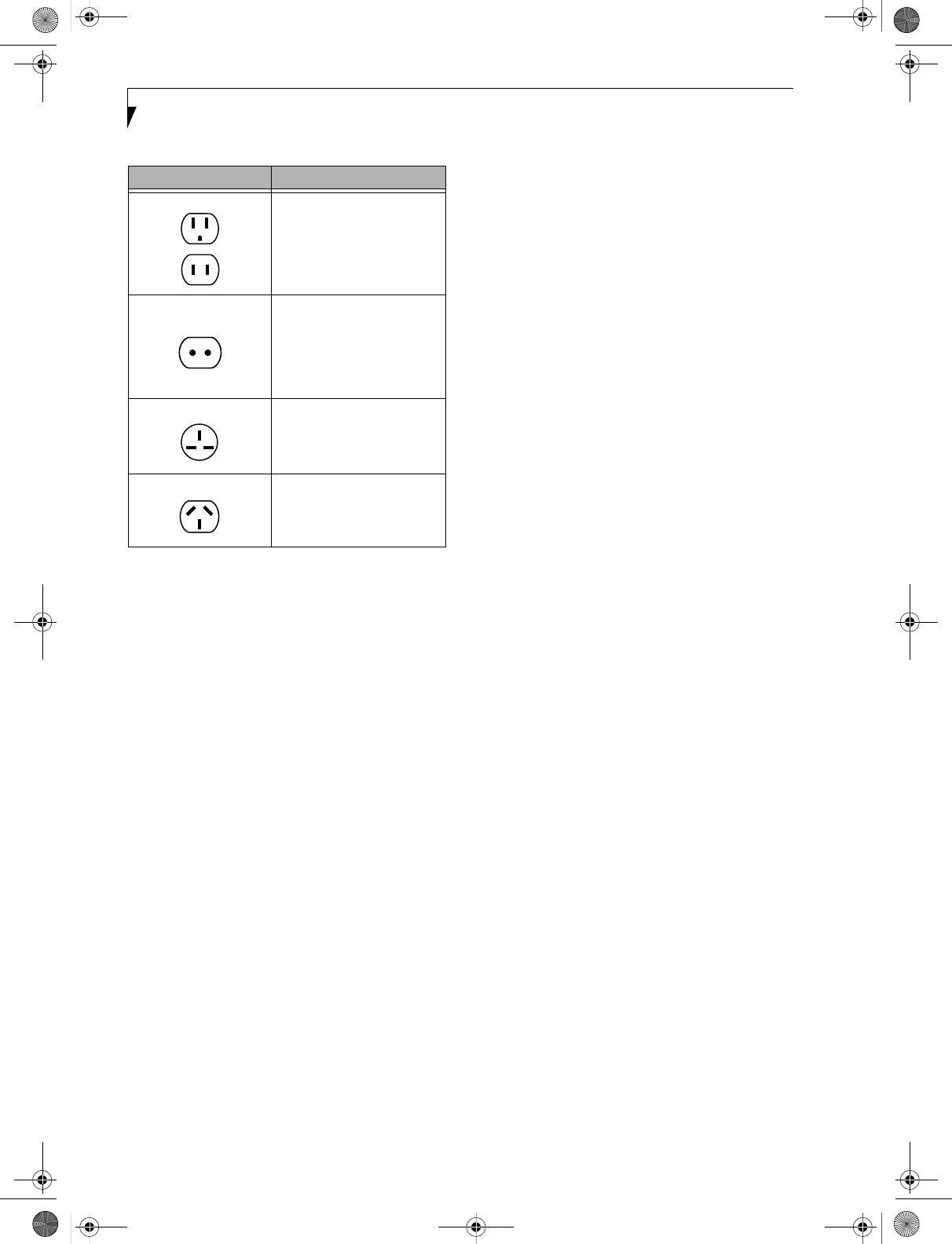
■Take the necessary plug adapters if you're traveling over-
seas. Check the following diagram to determine which
plug adapter you'll need or ask your travel agent.
Electrical equipment may be hazardous if
misused. Operations of this product or simi-
lar products, must always be supervised by
an adult. Do not allow children access to
the interior of any electrical products and
do not permit them to handle any cables.
S Series.book Page 71 Thursday, February 12, 2004 4:15 PM
72
LifeBook S7000 Notebook
BATTERIES
Caring for your Batteries
■Always handle batteries carefully.
■Do not short-circuit the battery terminals (that is, do
not touch both terminals with a metal object). Do not
carry lose batteries in a pocket or purse where they may
mix with coins, keys, or other metal objects. Doing so
may cause an explosion or fire.
■Do not drop, puncture, disassemble, mutilate or incin-
erate the battery.
■Recharge batteries only as described in this manual and
only in ventilated areas.
■Do not leave batteries in hot locations for more than a
day or two. Intense heat can shorten battery life.
■Do not leave a battery in storage for longer than 6
months without recharging it.
Increasing Battery Life
■Power your LifeBook notebook through the AC or
optional auto/airline adapter whenever possible.
■If your notebook is running on battery power all day,
connect it to the AC adapter overnight to recharge the
battery.
■Keep brightness to the lowest level comfortable.
■Set the power management for maximum battery life.
■Put your notebook in Suspend mode when it is turned
on and you are not actually using it.
■Limit your media drive access.
■Disable the Media Player auto insert notification
function.
■Always use fully charged batteries.
■Eject PCMCIATM cards when not in use.
FLOPPY DISKS AND DRIVES
Caring for your Floppy Disks
■Avoid using the floppy disks in damp and dusty
locations.
■Never store a floppy disk near a magnet or magnetic
field.
■Do not use a pencil or an eraser on a disk or disk label.
■Avoid storing the floppy disks in extremely hot or cold
locations, or in locations subject to severe temperature
changes. Store at temperatures between 50º F (10ºC)
and 125ºF (52ºC).
■Do not touch the exposed part of the disk behind the
metal shutter.
■Never use the floppy disk drive with any liquid, metal,
or other foreign matter inside the floppy disk drive
or disk.
■Never disassemble your floppy disk drive.
MEDIA CARE
Caring for your Media (DVD/CD/CD-R)
Media discs are precision devices and will function reli-
ably if given reasonable care.
■Always store your media disc in its case when it is not in
use.
■Always handle discs by the edges and avoid touching the
surface.
■Avoid storing any media discs in extreme temperatures.
■Do not bend media discs or set heavy objects on them.
■Do not spill liquids on media discs.
■Do not scratch media discs.
■Do not get dust on media discs.
■Never write on the label surface with a ballpoint pen or
pencil. Always use a felt pen.
■If a media disc is subjected to a sudden change in tem-
perature, cold to warm condensation may form on the
surface. Wipe the moisture off with a clean, soft, lint
free cloth and let it dry at room temperature. DO NOT
use a hair dryer or heater to dry media discs.
■If a disc is dirty, use only a DVD/CD cleaner or wipe it
with a clean, soft, lint free cloth starting from the inner
edge and wiping to the outer edge.
Outlet Type Location
United States, Canada,
parts of Latin America,
Mexico, Japan, Korea,
the Philippines, Taiwan
Russia and the Commonwealth
of Independent States (CIS),
most of Europe, parts of Latin
America, the Middle East, parts
of Africa, Hong Kong, India,
most of South Asia
United Kingdom,
Ireland, Malaysia, Singapore,
parts of Africa
China, Australia,
New Zealand
S Series.book Page 72 Thursday, February 12, 2004 4:15 PM

73
Care and Maintenance
Caring for your Optical Drive
Your optical drive is durable but you must treat it with
care. Please pay attention to the following points:
■The drive rotates the compact disc at a very high speed.
Do not carry it around or subject it to shock
or vibration with the power on.
■Avoid using or storing the drive where it will be exposed
to extreme temperatures.
■Avoid using or storing the drive where it is damp or
dusty.
■Avoid using or storing the drive near magnets or devices
that generate strong magnetic fields.
■Avoid using or storing the drive where it will be
subjected to shock or vibration.
■Do not disassemble or dismantle the optical drive.
■Use of a commercially available lens cleaner is
recommended for regular maintenance of your drive.
PC CARDS
Caring for your PC Cards
PC Cards are durable, but you must treat them with
care. The documentation supplied with your PC Card
will provide specific information, but you should pay
attention to the following points:
■To keep out dust and dirt, store PC Cards in their
protective sleeves when they are not installed in your
LifeBook notebook.
■Avoid prolonged exposure to direct sunlight or
excessive heat.
■Keep the cards dry.
■Do not flex or bend the cards, and do not place heavy
objects on top of them.
■Do not force cards into the slot.
■Avoid dropping cards, or subjecting them to excessive
vibration.
S Series.book Page 73 Thursday, February 12, 2004 4:15 PM

74
LifeBook S7000 Notebook
S Series.book Page 74 Thursday, February 12, 2004 4:15 PM

75
7
Specifications
S Series.book Page 75 Thursday, February 12, 2004 4:15 PM

76
LifeBook S7000 Notebook
S Series.book Page 76 Thursday, February 12, 2004 4:15 PM
77
Specifications
Specifications
This section provides the hardware and environmental
specifications for your Fujitsu LifeBook notebook. Spec-
ifications of particular configurations will vary.
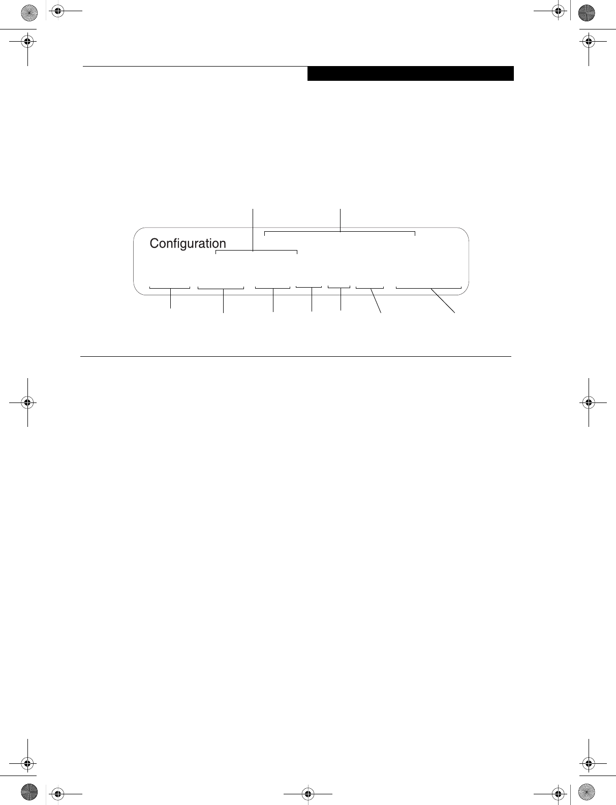
CONFIGURATION LABEL
There is a configuration label located on the bottom of
your LifeBook notebook. (See figure 2-8 on page 10 for
location) This label contains specific information
regarding the options you’ve chosen for your notebook.
Following is an example label and information on how to
read your own configuration label.
Figure 7-1 Configuration Label
MICROPROCESSOR
Intel Pentium M processor (Refer to the system label to
determine the speed of your processor).
CHIPSET
Intel 855GME
MEMORY
System Memory
DDR 333 MHz SDRAM memory module.
256 MB pre-installed in one DIMM slot;
one open DIMM slot available for upgrade.
Upgradeable to 2 GB of total memory (1 GB x 2)
Cache Memory
1MB L2 on-die
VIDEO
Built-in color flat-panel TFT active matrix LCD display
with simultaneous display capability
Video Color and Resolution
14.1" TFT XGA
■Internal: 1024 x 768 pixel resolution, 16M colors
■External: 1600 x 1200 pixel resolution, 16M colors
■Simultaneous Video: 1024 x 768, 16M colors. XGA,
SVGA and VGA compatible
Video RAM
Intel® 855GME video graphics chip with integrated 32-
bit 3D/2D gfx core with Accelerated Graphics Port
(AGP) support. Up to 64 MB shared video memory
using Dynamic Video Memory Technology (DVMT).
AUDIO
■Sigmatel ST9751T codec
■Stereo headphone jack, 3.5 mm, 1 Vrms or less,
minimum impedance 32 Ohms
■Mono microphone jack, 3.5 mm, 100 mVp-p or less,
minimum impedance 10K Ohms
■Two built-in stereo speakers, 20 mm diameter
MASS STORAGE DEVICE OPTIONS
Hard Drive
80 GB, 60 GB, 40 GB, or 30 GB fixed hard drive, Ultra
DMA 100 (4200 rpm), 2.5”, 9.5 mm
Media Player
Depending upon the configuration of your system, one
of the following is installed.
■CD Drive (modular 24x maximum), or,
■Combo DVD/CD-RW Drive (modular 8x maximum
DVD/24x maximum write, 10x maximum rewrite,
24x maximum read CD-RW combo drive), or,
■Super-Multi DVD Drive (modular 4x DVD-R, 2x
DVD-RW, 2.4x DVD+R, 2.4x DVD+RW, 2x DVD-
RAM, 8x DVD-ROM, 16x CD-R, 8x CD-RW, 24x
CD-ROM)
ANAXXXXXXXXXXXXX
S6120, PM 1.4G, 13XGA, XPP, 30G, 256M, LAN/WLAN
P/N:
FPC P/N: FPCM4061A
Operating Hard Drive
Configuration IDPart Number
Processor
Model # Screen Size Memory
System
Communications
S Series.book Page 77 Thursday, February 12, 2004 4:15 PM
78
LifeBook S7000 Notebook
FEATURES
Integrated Pointing Device
■Touchpad pointing device with scroll button
■Optional Quick Point cursor control button
Communications
Modem: Internal V.90 standard 56K fax/modem
(ITU V.90, 56K data, 14.4K fax)
Gigabit LAN: Internal wired 10Base-T/100Base-Tx/
1000Base-T/Tx Ethernet LAN
Wireless LAN:
Certain configurations of the Lifebook S7000 notebook
have an optional Wireless LAN device installed. If you have
an IntelPRO device installed, your system is classified as a
Centrino product. If you have a Wireless LAN device other
than IntelPRO installed, your system is classified as a
Pentium M product. (For additional information about
the Wireless LAN device, refer to the Wireless LAN User’s
Guide on page 93).
■S7010 Model: Integrated Intel PRO Wireless LAN
(802.11b/g), Wi-Fi-compliant
■S7010D Model: Optional integrated Atheros Wireless
LAN (802.11a/b/g), Wi-Fi-compliant
■Optional Bluetooth device for wireless personal area
network communication
LifeBook Security/Application Panel
The Application Launcher buttons on your LifeBook
notebook default to the following applications:
Theft Prevention Lock
Lock slot for use with security restraint systems. The
Kensington locking system is recommended.
DEVICE PORTS
On the LifeBook notebook:
■PC Card slots for two Type I or Type II cards:
PCMCIA Standard 2.1 with CardBus support
■One 15-pin D-SUB connector for VGA external
monitor (see Display specifications)
■Three USB 2.0 (Universal Serial Bus) connectors for
input/output devices
■One IEEE 1394 (4-pin type) jack
■One stereo line-in jack
■One modular modem (RJ-11) connector
■One LAN (RJ-45) connector
■One stereo headphone jack. (See Audio specifications)
■One mono microphone jack. (See Audio specifications)
■Embedded Smart Card Reader (requires third-party
application)
■Wireless LAN antenna with pre-installed on/off switch
■Optional Bluetooth module with antenna
On the Optional Port Replicator:
■One 6-pin mini DIN PS/2 compatible connectors for
external keyboard or mouse
■One 25-pin D-SUB connector for parallel input/
output devices; Bi-directional, output only or ECP
■One 15-pin D-SUB connector for VGA external
monitor (see Display specifications)
■One 9-pin D-SUB connector for RS-232C serial
input/output devices
■Four USB 2.0 (Universal Serial Bus) connectors for
input/output devices
■One LAN (RJ-45) connector
■One DC In connector
■One microphone In jack
■One headphone jack
■One Digital Video (DVI-D) jack
■One power/suspend/resume button
KEYBOARD
Built-in keyboard with all functions of 101 key PS/2
compatible keyboards.
■Total number of keys: 84
■Function keys: F1 through F12
■Feature extension key: Fn
■Two Windows keys: one Start key, one application key
■Key pitch: 19 mm
■Key stroke: 3 mm
■Built-in Touchpad pointing device with left and right
buttons and scroll button.
■Built-in Palm Rest
■Optional Quick Point cursor control button
External Keyboard Support
USB or PS/2-compatible (PS/2 compatible with Port
Replicator only)
External Mouse Support
USB or PS/2-compatible (PS/2 compatible with Port
Replicator only)
POWER
Batteries
One 6-cell Lithium ion battery, rechargeable, 10.8V,
4400 mAh, 47.5 Wh
Optional Flexible Bay battery: 6-cell Lithium ion battery,
rechargeable, 10.8V, 3400 mAh, 36.7 Wh
AC Adapter
Autosensing 100-240V AC, supplying 19V DC, 3.15A,
60W to the LifeBook notebook, Fujitsu Model
FPCAC26AP, which includes an AC cable.
Table 7-1 Application Launcher Defaults
Button
Label Button
Function Default Application
1 Application A Notepad
2 Application B Calculator
3 Internet Internet Explorer
4 E-Mail Netscape Messenger
S Series.book Page 78 Thursday, February 12, 2004 4:15 PM

79
Specifications
Power Management
Conforms to ACPI (Advanced Configuration and Power
Interface).
DIMENSIONS AND WEIGHT
Overall Dimensions
Approximately 12.05"(w) x 9.72"(d) x 1.0”/1.3"(h)
(306 mm x 247 mm x 25.4/33.0 mm)
Weights
Approximately 3.85 lbs (1.75 kg) with battery and
weight saver.
Approximately 4.3 lbs (1.95 kg) with battery and DVD/
CD-RW Combo drive.
ENVIRONMENTAL REQUIREMENTS
Temperature
Operating: 41° to 95° F (5° to 35° C)
Non-operating: 5° to 140° F (–15° to 60° C)
Humidity
Operating: 20% to 85%, relative, non-condensing
Non-operating; 8% to 85%, relative, non-condensing
Altitude
Operating: 10,000 feet (3,048 m) maximum
POPULAR ACCESSORIES
For ordering or additional information on
Fujitsu accessories please visit our Web site at
us.fujitsu.com/computers or call 1-800-733-0884.
Memory Upgrades
■256 MB SDRAM
■512 MB SDRAM
■1GB SDRAM
Docking
■Port Replicator
Power
■Main Lithium ion battery
■Battery Charger
■Auto/Airline Adapter
■AC Adapter
PC Cards
■Wireless PC Card
■4-in-1 Media Card Adapter
■Compact Flash Media Card Adapter
Additional Accessories
■Wireless Keyboard and Mouse
■External USB Floppy Disk Drive
■Presentation Audio System
■Tel eAd ap t 16 ' Tel eCord
■Notebook Guardian Lock
■IBM Modem Saver
Carrying Cases
■Diplomat
■Backpack
■Director
■MobileMax Wheeled Case
PRE-INSTALLED SOFTWARE
Depending on your pre-installed operating system, your
Fujitsu LifeBook notebook comes with pre-installed
software for playing audio and video files of various
formats. In addition there is file transfer software, virus
protection software and Power Management software.
The following list indicates the pre-installed software
associated with your system.
■Adobe Acrobat Reader
■Drive Image Special Edition (DISE)
■EarthLink 5.0
■BatteryAid
■Fujitsu HotKey/Fujitsu BatteryAid
■LifeBook Security/Application Panel
■Symantec Norton AntiVirus 2004 (90-day free trial)
■Netscape 7.0
■Quicken 2004 New User Edition
■Microsoft Works 7.0
■MS Reader*
■Journal Viewer*
■Zinio™ Reader*
■Newsstand™ Reader*
* Indicates that the software is available for user installa-
tion in the “third-party software”.
LEARNING ABOUT YOUR SOFTWARE
Tutorials
All operating systems and most application software
have tutorials built into them upon installation. We
highly recommend that you step through the tutorial
before you use an application.
Manuals
Included with your notebook you will find manuals for
your installed operating system and other pre-installed
software. Any manuals that are not included, are avail-
able online through the help system of the software. We
recommend that you review these manuals for general
information on the use of these applications.
Adobe Acrobat Reader
The Adobe Acrobat Reader, located in the Service and
Support Software folder, allows you to view, navigate,
and print PDF files from across all of the major
computing platforms.
BatteryAid (Windows 2000 only)
BatteryAid allows you to control the display brightness
of your notebook in order to maximize battery life. (See
your BatteryAid online help for more information on the
correct way to use this program)
S Series.book Page 79 Thursday, February 12, 2004 4:15 PM

80
LifeBook S7000 Notebook
Drive Image Special Edition (DISE) by PowerQuest
DISE by PowerQuest provides a way to restore your
computer if you experience a hard disk crash or other
system failure. DISE is used to restore the factory image
and restore the system to its original state.
Earthlink 5.0
Software suite that allows you to connect with the
Internet.
Fujitsu HotKey (Windows XP only)
Fujitsu HotKey allows you to control the display bright-
ness of your notebook in order to maximize battery life.
Quicken 2004 New User Edition
Quicken 2004 New User Edition by Intuit is a personal
money
management program. It has features such as portfolio
management, account registries, on-line banking
and bill paying features. This application is for new users
who are using Quicken software for the first time. Full
version upgrade information is available on line.
LifeBook Security/Application Panel Software
Your LifeBook notebook is pre-installed with software
utilities that let you operate and configure your LifeBook
Security/Application Panel.
The Security Panel portion allows for password protection
while the system is off or in Suspend mode. The Security
Panel utilities are found under the Start menu, under
Programs, then under LifeBook Security Panel.
The Application Panel utilities are found under the Start
menu, Settings/Control Panel, then Application Panel. To
open the CD Player and Application Panel Help, select
Start, Programs, LifeBook Application Panel.
Norton AntiVirus 2004
Your system is preinstalled with a free 90-day trial
version of Symantec’s Norton AntiVirus™ 2003. Norton
AntiVirus is a program designed to protect your Life-
Book notebook from computer viruses. It assists in the
protection of the data currently residing on your hard
disk from destruction or contamination. The 90-day
trial version is activated upon your acceptance of soft-
ware license agreement. After 90 days, it will be neces-
sary to purchase a subscription from Symantec to
download latest virus definitions.
Netscape 7.0
Browser suite, including integrated E-mail accounts,
instant messaging, address book, search, and other tools
and plug-ins.
S Series.book Page 80 Thursday, February 12, 2004 4:15 PM

81
8
Glossary
S Series.book Page 81 Thursday, February 12, 2004 4:15 PM

82
LifeBook S7000 Notebook
S Series.book Page 82 Thursday, February 12, 2004 4:15 PM

83
Glossary
Glossary
AC Adapter
A device which converts the AC voltage from a
wall outlet to the DC voltage needed to power
your LifeBook notebook.
ACPI
Advanced Configuration and Power Interface
Active-Matrix Display
A type of technology for making flat-panel displays
which has a transistor or similar device for every pixel
on the screen.
AdHoc
A name of a wireless LAN configuration.
It is a type of communication using wireless cards only.
Another type of communication is called Infrastructure
(using a wireless card and an access point).
ADSL
Asymmetric Digital Subscriber Line
Technology for transporting high bit-rate services over
ordinary phone lines.
AGP
Accelerated Graphics Port
Graphics port specifically designed for graphics-inten-
sive devices, such as video cards and 3D accelerators.
Auto/Airline Adapter
A device which converts the DC voltage from an auto-
mobile cigarette lighter or aircraft DC power outlet to
the DC voltage needed to power your LifeBook note-
book.
BIOS
Basic Input-Output System. A program and set of
default parameters stored in ROM which tests and
operates your LifeBook notebook when you turn it on
until it loads your installed operating system from disk.
Information from the BIOS is transferred to the installed
operating system to provide it with information on the
configuration and status of the hardware.
Bit
An abbreviation for binary digit. A single piece of
information which is either a one (1) or a zero (0).
bps
An abbreviation for bits per second. Used to describe
data transfer rates.
Boot
To start-up a computer and load its operating system
from disk, ROM or other storage media into RAM.
Bus
An electrical circuit which passes data between the CPU
and the sub-assemblies inside your LifeBook notebook.
Byte
8 bits of parallel binary information.
Cache Memory
A block of memory built into the micro-processor which
is much faster to access than your system RAM and used
in specially structured ways to make your overall data
handling time faster.
CardBus
A faster, 32-bit version of the PC Card interface which
offers performance similar to the 32-bit PCI
architecture.
CD-ROM
Compact disk read only memory. This is a form of
digital data storage which is read optically with a laser
rather than a magnetic head. A typical CD-ROM can
contain about 600MB of data and is not subject to heads
crashing into the surface and destroying the data when
there is a failure nor to wear from reading.
Channel
A radio frequency band used for communication
between wireless cards and access points.
CMOS RAM
Complementary metal oxide semiconductor random
access memory. This is a technology for manufacturing
random access memory which requires very low levels of
power to operate.
COM Port
Abbreviation for communication port. This is your
serial interface connection.
Command
An instruction which you give your operating system.
Example: run a particular application or format a floppy
disk.
S Series.book Page 83 Thursday, February 12, 2004 4:15 PM

84
LifeBook S7000 Notebook
Configuration
The combination of hardware and software that makes
up your system and how it is allocated for use.
CRT
Cathode Ray Tube. A display device which uses a beam
of electronic particles striking a luminescent screen. It
produces a visual image by varying the position and
intensity of the beam.
Data
The information a system stores and processes.
DC
Direct current. A voltage or current that does not
fluctuate periodically with time.
Default Value
A pre programmed value to be used if you fail to set your
own.
DHCP
Dynamic Host Configuration Protocol
A protocol used to automatically acquire parameters
required for the communication, such as IP address.
The sender of IP address is called a DHCP server, and
the receiver is called a DHCP client.
DIMM
Dual-in-line memory module.
DISE
Drive Image Special Edition.
A utility that allows you to restore the original factory
image on your hard drive in the event of corruption or
accidental erasure of files or applications.
Disk
A spinning platter of magnetic data storage media. If the
platter is very stiff it is a hard drive, if it is highly flexible
it is a floppy disk, if it is a floppy disk in a hard housing
with a shutter it is commonly called a diskette.
Disk Drive
The hardware which spins the disk and has the heads
and control circuitry for reading and writing the data
on the disk.
Diskette
A floppy disk in a hard housing with a shutter.
DMA
Direct Memory Access. Special circuitry for memory
to memory transfers of data which do not require
CPU action.
DMI
Desktop Management Interface. A standard that
provides PC management applications with a common
method of locally or remotely querying and configuring
PC computer systems, hardware and software compo-
nents, and peripherals.
DNS
Domain Name System
A function to control the association between the IP
address and the name assigned to the computer.
If you do not know the IP address but if you know the
computer name, you can still communicate to that
computer.
DOS
Disk Operating System (MS-DOS is a Microsoft Disk
Operating System).
Driver
A computer program which converts application and
operating system commands to external devices into the
exact form required by a specific brand and model of
device in order to produce the desired results from that
particular equipment.
DVMT
Dynamic Video Memory Technology
A video memory architecture that increases the
efficiency of the motherboard by using innovative
memory utilization and direct AGP.
ECP
Extended Capability Port. A set of standards for high
speed data communication and interconnection
between electronic devices.
Encryption Key (Network Key)
Key information used to encode data for data transfer.
This device uses the same encryption key to encode and
decode the data, and the identical encryption key is
required between the sender and receiver.
ESD
Electro-Static Discharge. The sudden discharge of elec-
tricity from a static charge which has built-up slowly.
S Series.book Page 84 Thursday, February 12, 2004 4:15 PM

85
Glossary
Example: the shock you get from a doorknob on a dry
day or the sparks you get from brushing hair on a dry
day.
Extended Memory
All memory more than the 640KB recognized by
MS-DOS as system memory.
FCC
Federal Communication Commission.
Floppy Disk
A spinning platter of magnetic data storage media which
is highly flexible.
GB
Gigabyte.
Hard drive
A spinning platter of magnetic data storage media where
the platter is very stiff.
I/O
Input/Output. Data entering and leaving your notebook
in electronic form.
I/O Port
The connector and associated control circuits for data
entering and leaving your notebook in electronic form.
IDE
Intelligent Drive Electronics. A type of control interface
for a hard drive which is inside the hard drive unit.
Infrared
Light just beyond the red portion of the visible light
spectrum which is invisible to humans.
Infrastructure
A name of a wireless LAN configuration. This type of
communication uses an access point.
Another type of communication is called AdHoc.
IP Address
An address used for computers to communicate in the
TCP/IP environment.
Current IPv4 (version 4) uses four values in the range
between 1 and 255. (Example: 192.168.100.123).
There are two types of IP address: global address and
private address.
The global address is an only address in the world. It is
controlled by JPNIC (Japan Network Information
Center). A private address is an only address in the
closed network.
IR
An abbreviation for infrared.
IrDA
Infrared Data Association. An organization which
produces standards for communication using infrared
as the carrier.
IRQ
Interrupt Request. An acronym for the hardware signal
to the CPU that an external event has occurred which
needs to be processed.
KB
Kilobyte.
LAN
Local Area Network. An interconnection of computers
and peripherals within a single limited geographic
location which can pass programs and data amongst
themselves.
LCD
Liquid Crystal Display. A type of display which makes
images by controlling the orientation of crystals in a
crystalline liquid.
Lithium ion Battery
A type of rechargeable battery which has a high power-
time life for its size and is not subject to the memory
effect as Nickel Cadmium batteries.
LPT Port
Line Printer Port. A way of referring to parallel interface
ports because historically line printers were the first and
latter the most common device connected to parallel
ports.
MAC Address
Media Access Control Address
A unique physical address of a network card. For
Ethernet, the first three bytes are used as the vendor
code, controlled and assigned by IEEE. The remaining
three bytes are controlled by each vendor (preventing
overlap), therefore, every Ethernet card is given a unique
physical address in the world, being assigned with a
different address from other cards. For Ethernet, frames
are sent and received based on this address.
MB
Megabyte.
S Series.book Page 85 Thursday, February 12, 2004 4:15 PM

86
LifeBook S7000 Notebook
Megahertz
1,000,000 cycles per second.
Memory
A repository for data and applications which is readily
accessible to your LifeBook notebook’s CPU.
MHz
Megahertz.
MIDI
Musical Instrument Digital Interface. A standard
communication protocol for exchange of information
between computers and sound producers such
as synthesizers.
Modem
A contraction for MOdulator-DEModulator. The
equipment which connects a computer or other data
terminal to a communication line.
Monaural
A system using one channel to process sound from all
sources.
MPU-401
A standard for MIDI interfaces and connectors.
MTU
Maximum Transmission Unit
The maximum data size that can be transferred at a time
through the Internet or other networks. You can set a
smaller MTU size to obtain successful communication,
if you have difficulty transferring data due to the fact
that the maximum size is too large.
Norton AntiVirus
Web-based software that protects you email, instant
messages, and other files by removing viruses, worms,
and Trojan horses.
NTSC
National TV Standards Commission. The standard for
TV broadcast and reception for the USA.
Operating System
A group of control programs that convert application
commands, including driver programs, into the exact
form required by a specific brand and model of micro-
processor in order to produce the desired results from
that particular equipment.
Partition
A block of space on a hard drive which is set aside and
made to appear to the operating system as if it were a
separate disk, and addressed by the operating system
accordingly.
PCI
Peripheral Component Interconnect
Self-configuring PC local bus. Designed by Intel, PCI has
gained wide acceptance as a standard bus design.
PCMCIA
PCMCIA is a trademark of the Personal Computer
Memory Card International Association. The Personal
Computer Memory Card International Association is an
organization that sets standards for add-in cards for
personal computers.
Peripheral Device
A piece of equipment which performs a specific
function associated with but not integral to a computer.
Examples: a printer, a modem, a CD-ROM.
Pitch (keyboard)
The distance between the centers of the letter keys of a
keyboard.
Pixel
The smallest element of a display, a dot of color on your
display screen. The more pixels per area the clearer your
image will appear.
POST
Power On Self Test. A program which is part of the BIOS
which checks the configuration and operating condition
of your hardware whenever power is applied to your
notebook. Status and error messages may be displayed
before the operating system is loaded. If the self test
detects failures that are so serious that operation can not
continue, the operating system will not be loaded.
PPPoE
Point to Point Protocol over Ethernet.
A protocol for Ethernet, using a Point-to-Point Protocol
(PPP), which is used for connection on the phone line.
Program
An integrated set of coded commands to your
computers telling your hardware what to do and how
and when to do it.
Protocol
S Series.book Page 86 Thursday, February 12, 2004 4:15 PM

87
Glossary
Procedures and rules use to send and receive data
between computers.
- Method of sending and receiving data
- Process used to handle communication errors
Conditions required for communication are organized
in procedures for correct transfer of information.
RAM
Random Access Memory. A hardware component of
your LifeBook notebook that holds binary information
(both program and data) as long as it has the proper
power applied to it.
RAM Module
A printed circuit card with memory and associated
circuitry which allows the user to add additional
memory to the computer without special tools.
Reset
The act of reloading the operating system. A reset erases
all information stored in RAM.
Restart
See Reset.
Resume
To proceed after interruption. In your notebook this
refers to returning to active operation after having been
in one of the suspension states.
ROM
Read Only Memory. A form of memory in which infor-
mation is stored by physically altering the material. Data
stored in this way can not be changed by your notebook
and does not require power to maintain it.
SDRAM
Synchronous Dynamic Random Access Memory.
Serial Port
A connection to another device through which data is
transferred one bit at a time on a single wire with any
other wires only for control of the device not for transfer
of data.
SMART
Self-Monitoring, Analysis and Reporting Technology
(SMART) is an emerging technology that provides near-
term failure predictions for hard drives. When SMART is
enabled the hard drive monitors pre-determined drive
attributes that are susceptible to degradation over time.
If a failure is likely to occur, SMART makes a status
report available so that the LifeBook notebook can
prompt the user to back up the data on the drive. Natu-
rally not all failures are predictable. SMART predict-
ability is limited to those attributes which the drive can
self-monitor. In those cases where SMART can give
advance warning, a considerable amount of precious
data can be saved.
SRAM
Static random access memory. A specific technology of
making RAM which does not require periodic data
refreshing.
SSID
Service Set Identifier
Specifies which network you are joining. Some systems
allow you to specify any SSID as an option so you can
join any network.
Standby
To make inoperative for a period of time. Your LifeBook
notebook uses various suspension states to reduce power
consumption and prolong the charge of your battery.
Status Indicator
A display which reports the condition of some portion
of your hardware. On your LifeBook notebook this is an
LCD screen just above the keyboard.
Stereo (audio)
A system using two channels to process sound from two
different sources.
SVGA
Super VGA.
S-Video
Super Video. A component video system for driving a
TV or computer monitor.
System Clock
An oscillator of fixed precise frequency which synchro-
nizes the operation of the system and is counted to
provide time of day and date.
TCP/IP
Transmission Control Protocol/Internet Protocol.
A standard Internet protocol that is most widely used.
TFT
Thin Film Transistor – A technology for flat display
panels which uses a thin film matrix of transistors to
control each pixel of the display screen individually.
S Series.book Page 87 Thursday, February 12, 2004 4:15 PM

88
LifeBook S7000 Notebook
UL
Underwriters Laboratories – An independent organiza-
tion that tests and certifies the electrical safety of devices.
USB
Universal Serial Bus.
Standard that allows you to simultaneously connect up
to 127 USB devices such as game pads, pointing devices,
printers, and keyboards to your computer.
VGA
Video Graphics Array. A video display standard
originally introduced by IBM with the PS/2 series of
personal computers.
VRAM
Video Random Access Memory. A memory dedicated to
video display data and control.
WFM
Wired for Management is Intel’s broad-based initiative
to reduce the total cost of ownership (TCO) of business
computing without sacrificing power and flexibility.
Wi-Fi Compatible
Wi-Fi (Wireless Fidelity) Identifies that the product has
passed the interoperability test, supplied by the WECA
(Wireless Ethernet Compatibility Alliance), which guar-
antees the interoperability of wireless IEEE 802.11 LAN
products. For more information on the Wi-Fi standard,
go to the WECA Web site at: www.wirelessethernet.com.
WLAN
Wireless Local Area Network. A wireless interconnection
of computers and peripherals within a single limited
geographic location which can pass programs and data
amongst themselves.
Write Protect
Prevent alteration of the binary state of all bits in a
storage media. Example: all information on a device
such as a floppy diskette; a block of space in a storage
media such as a partition of a hard drive; a file or direc-
tory of floppy diskette or hard drive.
XGA
Extended VGA.
Zip Drive
A 100MB or 250MB read/write removable media disk
drive.
S Series.book Page 88 Thursday, February 12, 2004 4:15 PM

89
Regulatory Information
Regulatory Information
NOTICE
Changes or modifications not expressly approved by
Fujitsu could void this user’s authority to operate the
equipment.
FCC NOTICES
Notice to Users of Radios and Television
These limits are designed to provide reasonable protec-
tion against harmful interference in a residential installa-
tion. This equipment generates, uses, and can radiate
radio frequency energy and, if not installed and used in
accordance with the instructions, may cause harmful
interference to radio communications. However, there is
no guarantee that interference will not occur in a partic-
ular installation. If this equipment does cause harmful
interference to radio or television reception, which can
be determined by turning the equipment off and on, the
user is encouraged to try to correct the interference by
one or more of the following measures:
nReorient or relocate the receiving antenna.
nIncrease the separation between the equipment and
receiver.
nConnect the equipment into an outlet that is on a
different circuit than the receiver.
nConsult the dealer or an experienced radio/TV
technician for help.
Shielded interconnect cables must be employed with this
equipment to ensure compliance with the pertinent RF
emission limits governing this device.
Notice to Users of the US Telephone Network
This equipment complies with Part 68 of the FCC rules,
and the requirements adopted by ACTA. On the bottom
of this equipment is a label that contains, among other
information, the FCC registration number and ringer
equivalence number (REN) for this equipment; or a
product identifier in the format US:AAAEQ##TXXXX.
If requested, this information or number must be
provided to the telephone company.
This equipment is designed to be connected to the tele-
phone network or premises wiring using a standard jack
type USOC RJ11C. A plug and jack used to connect this
equipment to the premises wiring and telephone
network must comply with the applicable FCC Part 68
rules and requirements adopted by the ACTA. A
compliant telephone cord and modular plug is provided
with this product. It is designed to be connected to a
compatible modular jack that is also compliant.
The ringer equivalent number (REN) of this equipment
is 0.0B as shown on the label. The REN is used to deter-
mine the number of devices that may be connected to a
telephone line. Excessive RENs on a telephone may
result in the devices not ringing in response to an
incoming call. In most but not all areas, the sum of
RENs should not exceed five (5.0). To be certain of the
number of devices that may be connected to a line, as
determined by the total RENs, contact the local tele-
phone company.
If this equipment causes harm to the telephone network,
the telephone company will notify you in advance that
temporary discontinuance of service may be required.
But if advance notice isn’t practical, the telephone
company will notify the customer as soon as possible.
Also, you will be advised of your right to file a complaint
with the FCC if you believe it is necessary.
The telephone company may make changes in its facili-
ties, equipment, operations or procedures that could
effect the operation of the equipment. If this happens
the telephone company will provide advance notice in
order for you to make necessary modifications to main-
tain uninterrupted service.
If trouble is experienced with this equipment, for repair
or warranty information, please refer to the manual or
contact Fujitsu Computer Systems Corporation,
Customer Service. If the equipment is causing harm to
the telephone network, the telephone company may
request that you disconnect the equipment until the
problem is resolved.
The equipment cannot be used on public coin service
provided by the telephone company. Connection to
party line service is subject to state tariffs. (Contact the
state public utility commission, public service commis-
sion or corporation commission for information).
If your home has specially wired alarm equipment
connected to the telephone line, ensure the installation
of this computer does not disable your alarm equip-
ment. If you have any questions about what will disable
alarm equipment, consult your telephone company or a
qualified installer.
The Telephone Consumer Protection Act of 1991 makes
it unlawful for any person to use a computer or other
electronic device to send any message via a telephone fax
machine unless such message clearly contains in a
margin at the top or bottom of each transmitted page or
on the first page of the transmission, the date an time it
is sent and an identification of the business or other
entity, or other individual sending the message and the
telephone number of the sending machine or such busi-
ness, other entity, or individual.
S Series.book Page 89 Thursday, February 12, 2004 4:15 PM
90
LifeBook S7000 Notebook
DOC (INDUSTRY CANADA) NOTICES
Notice to Users of Radios and Television
This Class B digital apparatus meets all requirements of
Canadian Interference-Causing Equipment Regulations.
CET appareil numérique de la class B respecte toutes les
exigence du Réglement sur le matérial brouilleur du
Canada.
Notice to Users of the Canadian Telephone Network
NOTICE: This equipment meets the applicable Industry
Canada Terminal Equipment Technical Specifications.
This is confirmed by the registration number. The
abbreviation, IC, before the registration number signi-
fies that registration was performed based on a Declara-
tion of Conformity indicating that Industry Canada
technical specifications were met. It does not imply that
Industry Canada approved the equipment.
Before connecting this equipment to a telephone line the
user should ensure that it is permissible to connect this
equipment to the local telecommunication facilities.
The user should be aware that compliance with the
certification standards does not prevent service
degradation in some situations.
Repairs to telecommunication equipment should be
made by a Canadian authorized maintenance facility.
Any repairs or alterations not expressly approved by
Fujitsu or any equipment failures may give the telecom-
munication company cause to request the user to
disconnect the equipment from the telephone line.
NOTICE: The Ringer Equivalence Number (REN) for
this terminal equipment is 0.0. The REN assigned to
each terminal equipment provides an indication of the
maximum number of terminals allowed to be connected
to a telephone interface. The termination on an interface
may consist of any combination of devices subject only
to the requirement that the sum of the Ringer Equiva-
lence Numbers of all the devices does not exceed five.
Avis Aux Utilisateurs Du Réseau
Téléphonique Canadien
AVIS: Le présent matériel est conforme aux spécifica-
tions techniques d’Industrie Canada applicables au
matériel terminal. Cette conformité est confirmée par le
numéro d’enregistrement. Le sigle IC, placé devant le
numéro d’enregistrement, signifie que l’enregistrement
s’est effectué conformément à une déclaration de
conformité et indique que les spécifications techniques
d’Industrie Canada ont été respectées. Il n’implique pas
qu’Industrie Canada a approuvé le matériel.
Avant de connecter cet équipement à une ligne télépho-
nique, l’utilisateur doit vérifier s’il est permis de
connecter cet équipement aux installations de télécom-
munications locales. L’utilisateur est averti que même la
conformité aux normes de certification ne peut dans
certains cas empêcher la dégradation du service.
Les réparations de l’équipement de télécommunications
doivent être eVectuées par un service de maintenance
agréé au Canada. Toute réparation ou modification, qui
n’est pas expressément approuvée par Fujitsu, ou toute
défaillance de l’équipement peut entraîner la compagnie
de télécommunications à exiger que l’utilisateur décon-
necte l’équipement de la ligne téléphonique.
AVIS: L’indice d’équivalence de la sonnerie (IES) du
présent matériel est de 0.0. L’IES assigné à chaque
dispositif terminal indique le nombre maximal de
terminaux qui peuvent être raccordés à une interface
téléphonique. La terminaison d’une interface peut
consister en une combinaison quelconque de dispositifs,
à la seule condition que la somme d’indices d’équiva-
lence de la sonnerie de tous les dispositifs n’excède pas 5.
For safety, users should ensure that the
electrical ground of the power utility, the
telephone lines and the metallic water
pipes are connected together. Users should
NOT attempt to make such connections
themselves but should contact the appro-
priate electric inspection authority or elec-
trician. This may be particularly important
in rural areas.
Pour assurer la sécurité, les utilisateurs
doivent vérifier que la prise de terre du ser-
vice d’électricité, les lignes télphoniques et
les conduites d’eau métalliques sont con-
nectées ensemble. Les utilisateurs NE
doivent PAS tenter d’établir ces connex-
ions eux-mêmes, mais doivent contacter
les services d’inspection d’installations
électriques appropriés ou un électricien.
Ceci peut être particulièrement important
en régions rurales.
S Series.book Page 90 Thursday, February 12, 2004 4:15 PM

91
Regulatory Information
UL Notice
This unit requires an AC adapter to operate. Use only UL
Listed Class 2 Adapters with an output rating of 19
VDC, with a current of 3.15 A.
AC Adapter output polarity:
For Authorized Repair Technicians Only
System Disposal
The modem-to-telephone network con-
nection must be a line cord using a mini-
mum #26 AWG wire.
nFor continued protection against risk of
fire, replace only with the same type and
rating fuse.
nDanger of explosion if Lithium (clock)
battery is incorrectly replaced. Replace
only with the same or equivalent type
recommended by the manufacturer. Dis-
pose of used batteries according to the
manufacturer’s instruction.
+
Hg
LAMP(S) INSIDE THIS PRODUCT
CONTAIN MERCURY AND MUST
BE RECYCLED OR DISPOSED OF
ACCORDING TO LOCAL, STATE, OR
FEDERAL LAWS.
S Series.book Page 91 Thursday, February 12, 2004 4:15 PM

92
LifeBook S7000 Notebook
S Series.book Page 92 Thursday, February 12, 2004 4:15 PM

93
Appendix
Integrated Wireless
LAN* User’s Guide
* Optional device
S Series.book Page 93 Thursday, February 12, 2004 4:15 PM

94
LifeBook S7000 Notebook
S Series.book Page 94 Thursday, February 12, 2004 4:15 PM

95
W Ireless L A N User’s Guide
FCC REGULATO RY INFO RM ATIO N
Please note the following regulatory information related to the
optional wireless LAN module.
Regulatory Notes and Statements
Wireless LAN, Health and Authorization for use
Radio frequency electromagnetic energy is emitted from Wire-
less LAN devices. T he energy levels of these emissions, however,
are far much less than the electromagnetic energy emissions
from wireless devices such as mobile phones. Wireless LAN
devices are safe for use by consumers because they operate
within the guidelines found in radio frequency safety standards
and recommendations. The use of Wireless LAN devices may be
restricted in some situations or environments, such as:
On board an airplane, or
In an explosive environment, or
In situations where the interference risk to other devices or
services is perceived or identified as harmful.
In cases in which the policy regarding use of Wireless LAN
devices in specific environments is not clear (e.g., airports,
hospitals, chemical/oil/gas industrial plants, private buildings),
obtain authorization to use these devices prior to operating the
equipment.
Regulatory Information/Disclaimers
Installation and use of this Wireless LAN device must be in
strict accordance with the instructions included in the user
documentation provided with the product. Any changes or
modifications made to this device that are not expressly
approved by the manufacturer may void the user’s authority to
operate the equipment. The manufacturer is not responsible for
any radio or television interference caused by unauthorized
modification of this device, or the substitution or attachment of
connecting cables and equipment other than those specified by
the manufacturer. It is the responsibility of the user to correct
any interference caused by such unauthorized modification,
substitution or attachment. T he manufacturer and its autho-
rized resellers or distributors will assume no liability for any
damage or violation of government regulations arising from
failure to comply with these guidelines.
This device must not be co-located or operating in conjunction
with any other antenna or transmitter.
For Atheros Wireless LAN:
For operation within 5.15~5.25GH z frequency range, it is
restricted to indoor environment, and the antenna of this
device must be integral.
Federal Communications Commission statement
This device complies with Part 15 of FCC Rules.
Operation is subject to the following two conditions: (1) This
device may not cause interference, and, (2) This device must
accept any interference, including interference that may cause
undesired operation of this device.
FCC Interference Statement
This equipment has been tested and found to comply with the
limits for a Class B digital device, pursuant to Part 15 of the
FCC Rules. These limits are designed to provide reasonable
protection against harmful interference in a residential installa-
tion. T his equipment generates, uses, and can radiate radio
frequency energy. If not installed and used in accordance with
the instructions, it may cause harmful interference to radio
communications. However, there is no guarantee that interfer-
ence will not occur in a particular installation.
If this equipment does cause harmful interference to radio or
television reception, which can be determined by turning the
equipment off and on, the user is encouraged to try and correct
the interference by one or more of the following measures:
1. Reorient or relocate the receiving antenna.
2. Increase the distance between the equipment and the
receiver.
3. Connect the equipment to an outlet on a circuit different
from the one the receiver is connected to.
4. Consult the dealer or an experienced radio/TV technician
for help.
FCC Radiation Exposure Statement
This equipment complies with FCC radiation exposure limits
set forth for an uncontrolled environment. T his equipment
should be installed and operated with a minimum distance of
20 centimeters between the Wireless LAN/Bluetooth antenna
(located on the top edge of the LCD screen) and your body.
Export Restrictions
This product or software contains encryption code which may
not be exported or transferred from the US or Canada without
an approved US Department of Commerce export license. This
device complies with Part 15 of FCC Rules., as well as ICES 003
B / NMB 003 B. Operation is subject to the following two
conditions: (1) this device may not cause harmful interference,
and (2) this device must accept any interference received,
including interference that may cause undesirable operation.
Modifications not expressly authorized by Fujitsu PC Corpora-
tion may invalidate the user's right to operate this equipment.
Canadian Notice
To prevent radio interference to the licensed service, this device
is intended to be operated indoors and away from windows to
provide maximum shielding. Equipment (or its transmit
antenna) that is installed outdoors is subject to licensing.
S Series.book Page 95 Thursday, February 12, 2004 4:15 PM
The transmitters in this device must not be co-located or
operated in conjunction with any other antenna or transmitter.
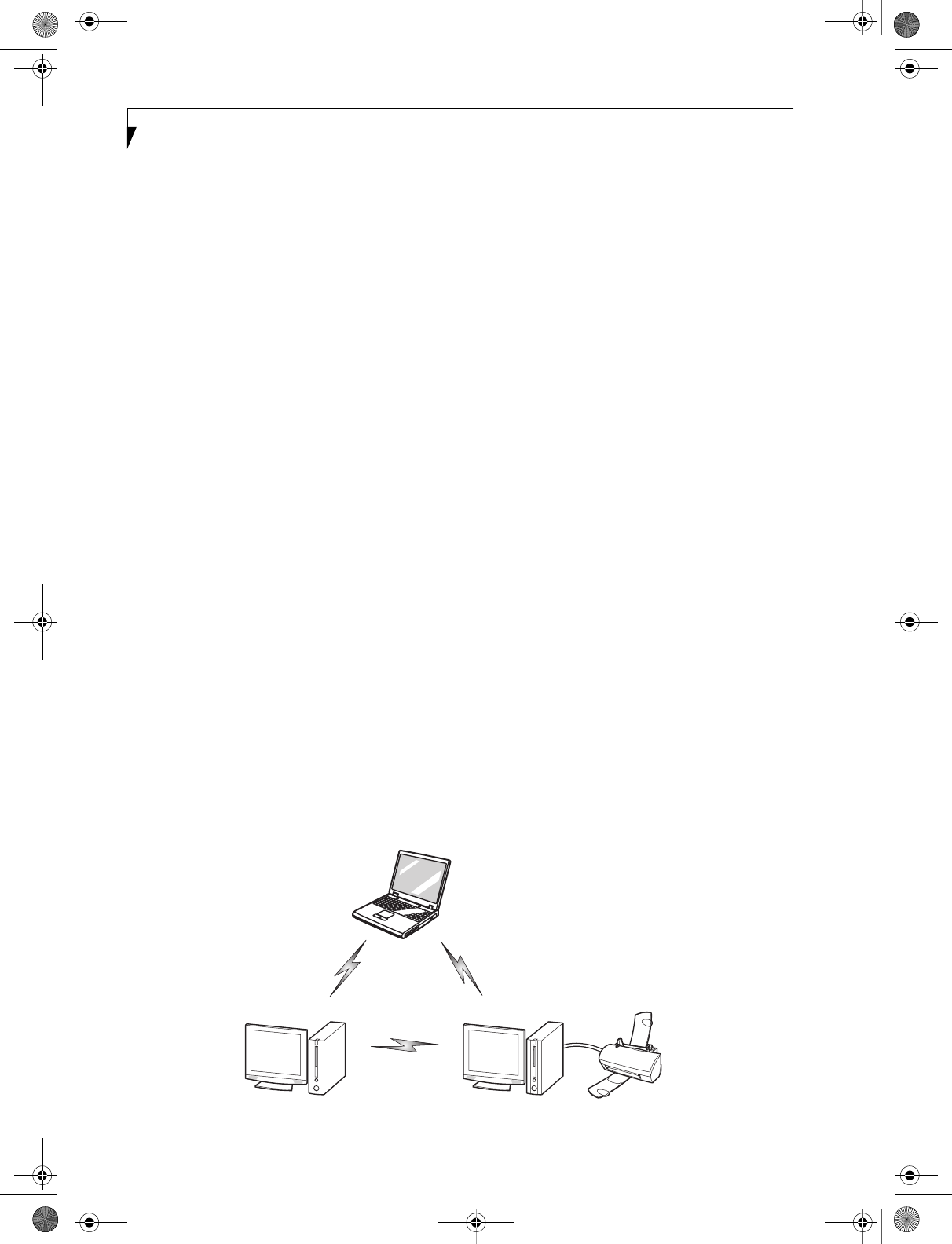
96
LifeBook S7000 Notebook
Before Using the Wireless LAN
The Integrated Wireless LAN is an optional device avail-
able for Fujitsu mobile computers. This manual
describes the basic operating procedures for the Wireless
LAN (referred to as the “device” in this manual) and
how to set up a wireless LAN network. Before using this
device, read this manual carefully to ensure correct oper-
ation of the device. Keep this manual in a safe place for
reference while using the device.
Types of Wireless LANs Covered by this Document
This document is applicable to systems containing one
of the following two devices. Most of the procedures are
identical. Sections that differ between the two devices
have been noted in the text:
■Intel PROSet Wireless LAN
■Atheros Wireless LAN
If your system is a Stylistic S7010, your wireless module
is the Intel PROSet wireless LAN; if your system is a
Stylistic S7010D, your wireless module is the Atheros
wireless LAN;
Characteristics of the Device
This device consists of a wireless LAN card that is
attached inside the computer via a mini-PCI slot.
The main characteristics are as follows:
■It operates in the 2.4 GHz Industrial, Scientific, and
Medical (ISM) RF band; additionally, the Atheros
wireless LAN operates in the 5 GHz RF band.
■It does not require an FCC license to operate.
■It uses Direct Sequence Spread Spectrum (DSSS), an
RF modulation scheme that is resistant to noise.
■This wireless module is Wi-Fi compliant. The module
can communicate at a maximum data rate of 54 Mbps.
■The maximum communication range is approxi-
mately 80 feet (25 meters) inside a building. Please
note that the range you achieve may be shorter or
longer than 80 feet, depending upon factors such as
obstructions, walls, columns, construction material,
and reflective objects.
■The wireless module s support a number of industry-
standard security mechanisms, including WEP, TKIP,
and 802.1x/EAP (LEAP, TLS, PEAP, MD5).
Wireless LAN Modes Using this Device
Ad Hoc Mode (See Figure 1)
“Ad Hoc Mode” refers to a type of wireless network that
involves connecting multiple computers without the use
of an Access Point. Network connectivity between
computers can be established using only wireless LAN
cards in a peer-to-peer fashion.
Ad Hoc networks are an easy and inexpensive method
for establishing network connectivity between multiple
computers.
In the Ad Hoc mode, you can use the function
supported by Microsoft Network, such as File and Print
Sharing to exchange files and share a printer or other
peripheral devices.
To use Ad Hoc Mode, you must set the same SSID and
the same encryption key for all the computers that are
connected. Communication between computers in an
Ad Hoc network will occur provided they are within
each other’s RF coverage area.
Figure 1. Ad Hoc Mode Network
S Series.book Page 96 Thursday, February 12, 2004 4:15 PM
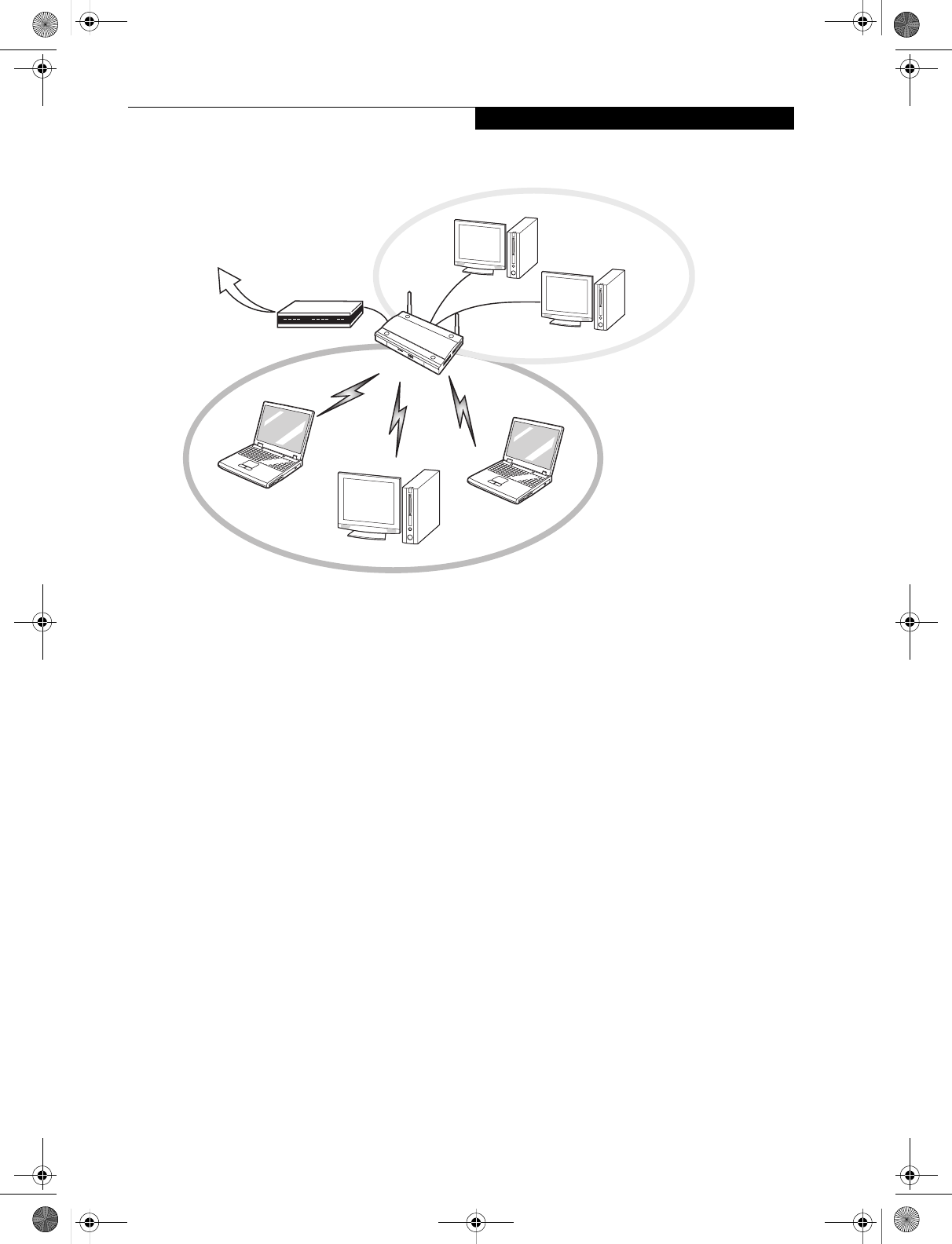
97
WIreless LAN User’s Guide
Access Point (Infrastructure) Mode (See Figure 2)
If a number of computers are connected simultaneously
in the Ad Hoc mode, the transfer rate may be reduced,
communications may become unstable, or the network
connection could fail. This is because all wireless LAN
cards are using the same radio frequency in the network.
To improve this situation, you can use a wireless LAN
access point, which is sold separately. The wireless LAN
network is in the “Access Point mode” when it uses an
access point, and such a connection is called the “Access
Point Network” or “Infrastructure Network”.
By using an access point, you can set and use a different
communication channel for each network group. Each
channel is given a different radio frequency, and it
eliminates the collision of communications and provides
a more stable communications environment.
How to Handle This Device
The Integrated Wireless LAN device is already installed
in your mobile computer. Under normal circumstances,
it should not be necessary for you to remove or re-install
it. The LAN has been configured to support the oper-
ating system with which your system shipped.
FOR BETTER COMMUNICATIONS
This personal computer may not operate properly due to
the operating environment. Strictly observe the
following precautions when installing the main unit of
the computer:
■For optimum wireless communications, it recom-
mended that operation of the wireless LAN module
occur within 25 meters of the Access Point. Wireless
range is dependent on a multitude of factors including
number of obstructions, walls, type of construction
material, reflective objects, etc.
■If the computer is unable to communicate properly,
change the channel to be used or the installation loca-
tion. During the use of a microwave oven or other
equipment generating strong high-frequency energy,
in particular, the personal computer may be highly
susceptible to the energy and unable to communicate
properly.
■Broadcast stations or wireless communication equip-
ment that operate in the 2.4GHz or 5GHz RF Fre-
quency band may interfere with the operation of the
wireless LAN module. Increasing of transmit power or
relocating Access Points may be necessary to combat
the effects of the interference.
Figure 2. Access Point (Infrastructure) Mode Network
Internet ADSL modem,
cable modem,
or similar
Wired LAN
Wireless LAN
Access Point*
* An optional hub for a wired
LAN may be required depending
upon the type of access point used.
S Series.book Page 97 Thursday, February 12, 2004 4:15 PM
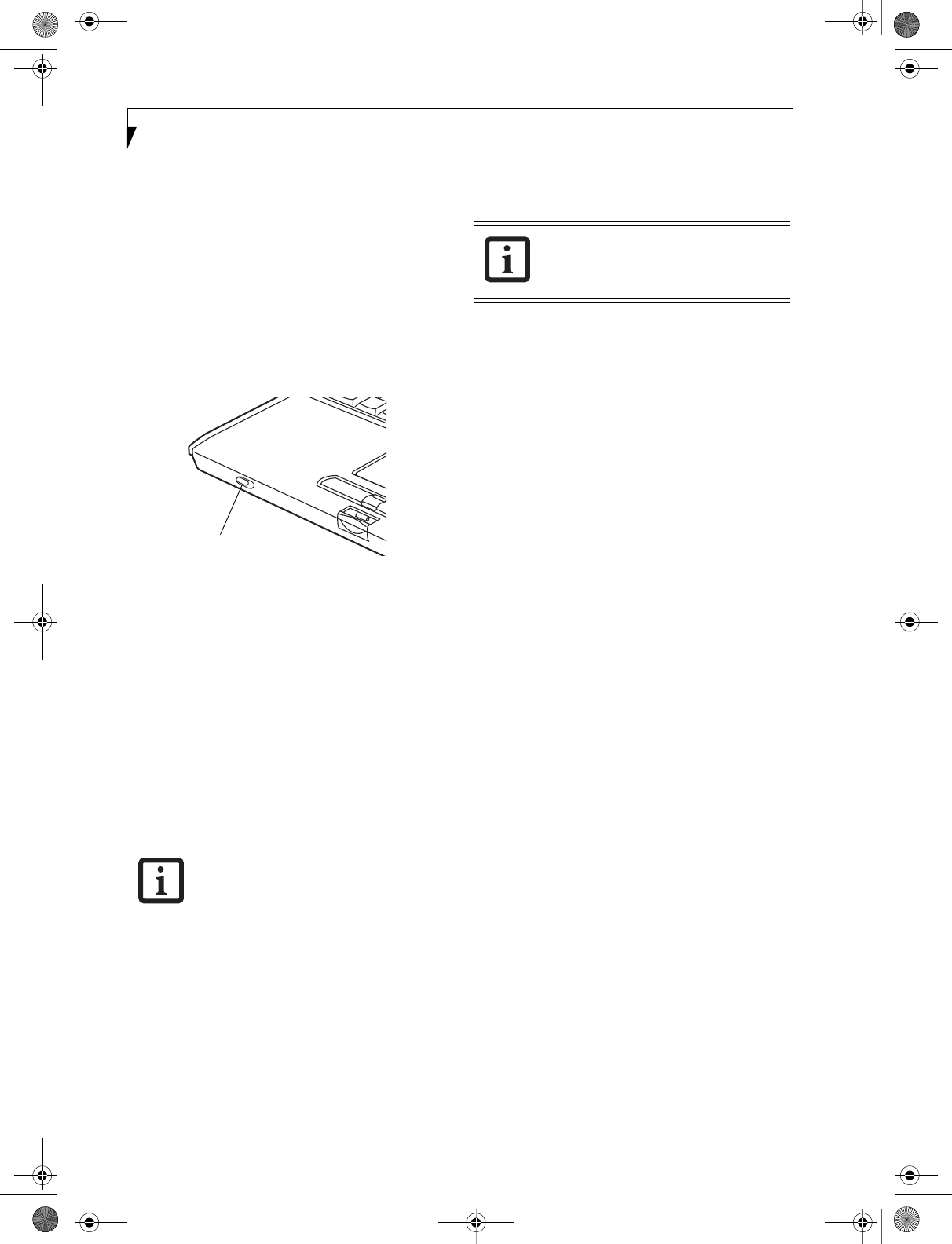
98
LifeBook S7000 Notebook
STOPPING TRANSMISSION
To use this product inside hospitals, clinics, or airplanes,
or in other places where the use of electronic equipment
is regulated, stop the transmission of radio waves from
the wireless LAN beforehand.
Deactivation using the wireless switch
The transmission of radio waves from the wireless LAN
can be stopped by setting the wireless switch to the Off
position. Note that the Wireless LAN On/Off switch has
no effect on non-Wireless LAN models.
(See Figure 3 for Wireless LAN switch location.)
Figure 3. Wireless LAN On/Off Switch
Deactivation using Windows
Intel PROSet Wireless LAN:
1. Click [Start] --> [(All) Programs] --> [Intel Net-
work Adapters] --> [Intel(R) PROSet]. The
Intel(R) PROSet window will be displayed.
2. Click the General tab.
3. Select [Off] for the wireless communications
Switch Radio: function, and then click the [OK]
button. Wireless communications on/off switching
will be deactivated and the transmission of radio
waves from the wireless LAN will be stopped.
Atheros Wireless LAN
1. Click [Start] --> [Settings (Windows 2000 only)]
-> [Control Panel] --> [Atheros Wireless Utility].
The Atheros Wireless Configuration Utility win-
dow will be displayed.
2. Click the Wireless Networks tab.
3. Click the [Enable Radio] box to clear it, then click
the [OK] button. Wireless communications on/off
switching will be deactivated and the transmission
of radio waves from the wireless LAN will be
stopped.
STARTING TRANSMISSION
To communicate using the wireless LAN function, set
the computer to a status from which it can transmit, as
follows:
Intel PROSet Wireless LAN:
1. Set the wireless switch to the On position.
2. Click [Start] --> [(All) Programs] --> [Intel Net-
work Adapters] --> [Intel(R) PROSet]. The
Intel(R) PROSet window will be displayed.
3. Click the [General] tab if it is not already selected.
4. Select [ON] for the Switch radio: function, then
click [OK]. Wireless communications on/off
switching will be activated and the transmission of
radio waves will be restarted.
Atheros Wireless LAN:
1. Click the Wireless Network Connection icon in the
system tray at the lower right of your screen.
2. Click [Enable Radio]. The radio will be turned on.
Access Point Mode: Transmission is enabled.
Ad Hoc Mode: Restart your computer to enable the
radio.
To restart transmission, select [On] for the
wireless communications Switch Radio:
function, and then click the [OK] button.
Wireless LAN
On/Off Switch
To restart transmission, check the [Enable
Radio] checkbox to select it., then click the
[OK] button.
S Series.book Page 98 Thursday, February 12, 2004 4:15 PM

99
WIreless LAN User’s Guide
Connection using Wireless Zero Configuration Tool
FLOW OF OPERATIONS
The wireless LAN connection procedure contained in
this section is outlined below.
1. Make sure the mobile computer is ready for the
transmission of radio waves from the wireless LAN.
For further details, see (See Starting Transmission
on page 98 for more information).
2. Assign the parameters required for wireless LAN
connection. (See Preparation for wireless LAN con-
nection on page 99 for more information).
■Enter the network name (SSID) and other data.
■Enter the network key (the Wired Equivalent
Privacy or WEP key used to encode 802.11b
communications data).
3. Perform setting operations relating to network con-
nection. (See Connection to the network on page 101
for more information)
■Specify TCP/IP as the protocol, and confirm the name
of the work group and other settings.
■Enter the data required for file/printer sharing on the
network. Perform this operation as required.
■For access point (or “infrastructure”) connection,
enter data for the access point. Refer to the manual of
the access point for further details.
■Verify that you are able to connect your computer to
the network.
PREPARATION FOR WIRELESS LAN
CONNECTION
This section explains the preparations required for the
use of the wireless LAN.
Assigning parameters
Configure the network name (SSID), the network key,
and other data required for wireless LAN connection.
Please contact your network administrator for the
correct configuration parameters.
1. Make sure the Wireless LAN switch is switched on.
2. Click the [Start] button first and then [Control
Panel].
3. If the Control Panel is in Category view, switch to
Classic view by clicking “Switch to Classic View”
under Control Panel the left frame. (If you are
already in Classic view, “Switch to Category View”
will be displayed instead.)
4. Double-click the Network Connections icon. A list
of currently installed networks will be displayed.
5. Right-click [Wireless Network Connection] in the
list, and then click [Properties] in the menu dis-
played. The [Wireless Network Connection Proper-
ties] window will be displayed.
6. Click the [Wireless Networks] tab.
7. Click [Refresh], then choose the correct SSID from
the [Available Networks] window. Click [Config-
ure] and proceed to step 8. If the SSID of your
access point does not appear in the list, click [Add].
The [Wireless Network Properties] window will be
displayed.
8. Select the Association tab if it is not already
selected.
9. Enter the information required for connection to
the wireless LAN, as follows.
a. Enter the network name (SSID). (i.e., Enter the
name of the desired network in less than 33
ASCII characters).
For ad hoc connection: Assign the same network
name to all the personal computers to be
connected.
■To use access point (infrastructure) con-
nection, refer to the access point manual
for the access point-setting procedure.
■You do not need to set the channel
when using access point (infrastructure)
mode. Channel selection is controlled by
the access point. In ad hoc networks,
channel selection defaults to channel 11;
however, channel selection can be man-
ually changed if desired. This can be
accomplished only when using the client
utility.
If it is necessary to change the channel,
change the setting of the access point.
For the setting procedure, refer to the
manual of the access point.
S Series.book Page 99 Thursday, February 12, 2004 4:15 PM
100
LifeBook S7000 Notebook
For access point (infrastructure) connection:
Assign the appropriate SSID. The SSID must be
identical to the SSID of the access point. Refer to
the access point manual, or contact your network
administrator.
b. For ad hoc connection, check the following field.
For access point (infrastructure) connection,
clear the check mark for the following field:
[This is a computer-to-computer (ad hoc) net-
work; wireless access points are not used.]
10. Configure Wireless Network Key parameters (Net-
work Authentication and Encryption).
a. Choose the Network Authentication method
appropriate for your wireless LAN. Options
include Open, Shared, WPA, and WPA-PSK.
b. Choose the Encryption method appropriate for
your wireless LAN. Options for Open or Shared
Authentication are Disabled or WEP. Options for
WPA or WPA-PSK are TKIP or AES.
c. If using static WEP keys, clear the check mark
from the [The key is provided for me automati-
cally] check box. If using an authentication
method that uses dynamic WEP (e.g., WPA,
WPA-PSK, 802.1x/EAP), the check box should
remain checked. Please consult your network
administrator for the correct settings.
d. Static WEP keys are to be entered in the
[Network Key] box. Configuration of the
[Network Key] is not required if the [The key is
provided for me automatically] check box is
checked.
■Static WEP keys entered in ASCII code format
will be either five characters (40-bit) or thir-
teen characters (104-bit) in length. Valid char-
acters are 0 - 9, A - Z.
■Static WEP keys entered in hexadecimal code
format will be either ten characters (40-bit) or
twenty-six characters (104-bit) in length. Valid
characters are 0 - 9, A - F.
For ad hoc connection: Assign the same net-
work key to all the personal computers to be
connected.
For access point (infrastructure) connection:
Assign the identical network key that is pro-
grammed into the access point. For this set-
ting, refer to the access point manual or
contact your network administrator.
e. If using static WEP keys, confirm the Network
key by re-entering the same data in the [Confirm
network key:] field.
11. Click the [Authentication] tab and then verify the
settings of [Enable IEEE 802.1x authentication for
this network].
For internal use at an organization such as a com-
pany, when access by wireless LAN clients is to be
limited using IEEE 802.1x authentication, check the
[Enable IEEE 802.1x authentication for this net-
work] check box.
For home use, clear the check mark from [Enable
IEEE 802.1x authentication for this network].
For the setting method relating to IEEE 802.1x
authentication, refer to the manual of the access
point which you are using.
12. After completion of setting operations, click the
[OK] button. Processing will return to the [Wire-
less Network Connection Properties] window.
13. Verify that the network name entered in step 7
above is added in [Preferred Networks], and then
click the [OK] button.
14. Close the [Wireless Network] window.
It is strongly recommended that you enter
the network key for encoding
communications data. If the network key
is not entered, since the network can be
accessed from all personal computers
containing the wireless LAN function,
there is the danger of your data being
stolen or damaged by other users.
In [Preferred Networks], register only the
desired connection settings.
S Series.book Page 100 Thursday, February 12, 2004 4:15 PM
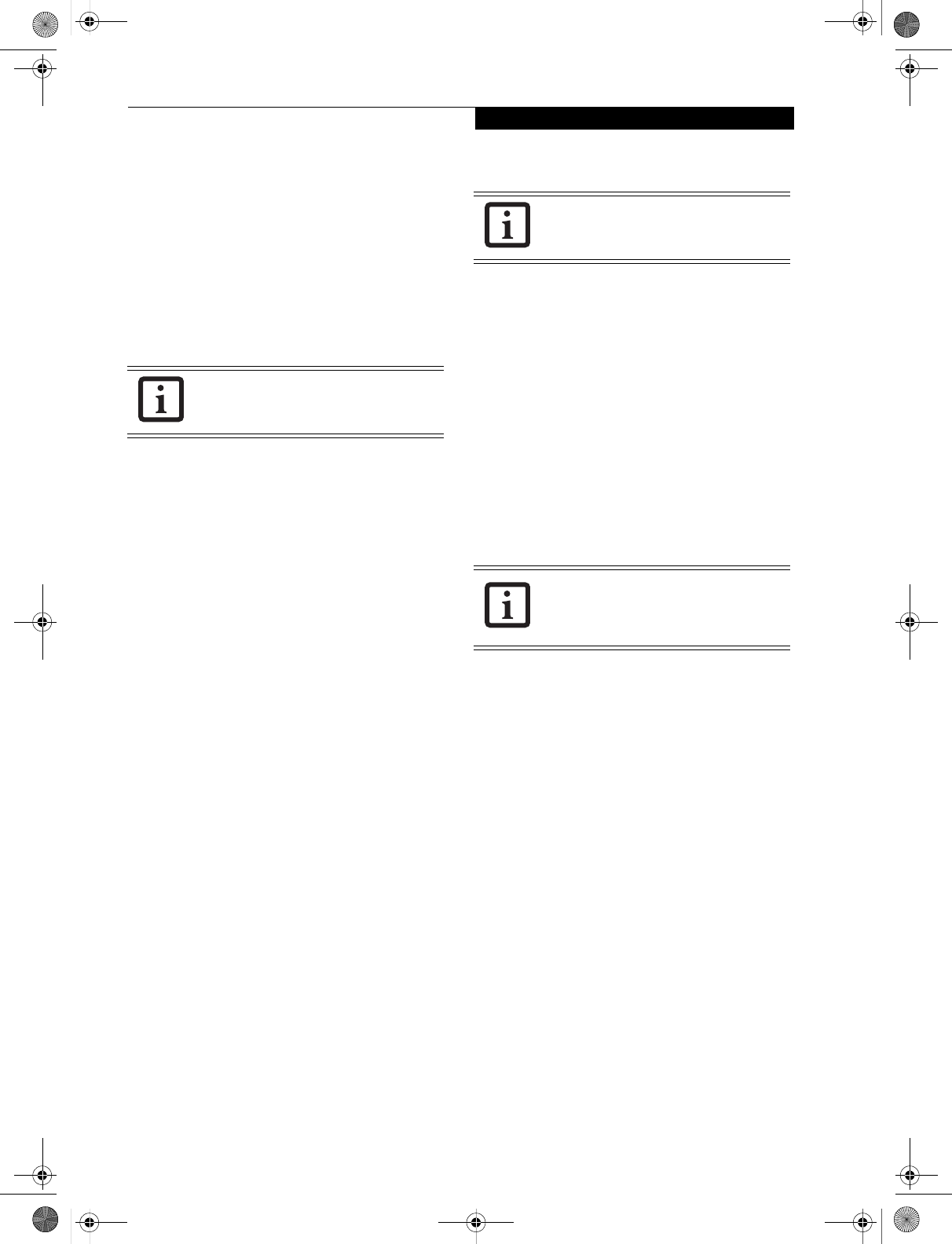
101
WIreless LAN User’s Guide
CONNECTION TO THE NETWORK
This section explains connection to the network.
If there is an administrator of the network, contact the
network administrator for data settings.
Setting the network
Perform the “Setting TCP/IP” and “Confirming the
computer and work group names” operations required for
network connection.
Setting TCP/IP
1. Click the [Start] button first and then [Control
Panel].
2. If the Control Panel is in Category view, switch to
Classic view by clicking “Switch to Classic View”
under Control Panel the left frame. (If you are
already in Classic view, “Switch to Category View”
will be displayed.)
3. Double-click [Network Connections]. A list of cur-
rently installed networks will be displayed.
4. Right-click [Wireless Network Connection] in the
list, and then click [Properties] in the menu dis-
played. The [Wireless Network Connection Proper-
ties] window will be displayed.
5. Click the [General] tab if it is not already selected.
6. Click [Internet Protocol (TCP/IP] and then click
[Properties]. The [Internet Protocol (TCP/IP)
Properties] window will be displayed.
7. Set the IP address as follows:
■For ad hoc connection: Select [Use the following
IP address:] and then enter data for [IP address]
and [Subnet mask]. See page 115 for IP address
setting.
■For access point (infrastructure) connection: If
your network uses DHCP, select [Obtain an IP
address automatically] and [Obtain DNS server
address automatically]. If your network uses static
IP addresses, consult with your network adminis-
trator for the correct IP address settings.
8. Click the [OK] button. Processing will return to the
[Wireless Network Connection Properties] window.
9. Click the [OK] button.
10. Close the [Network Connection] window.
Following this operation, confirm the names of the
computer and the workgroup as follows.
Confirming the computer and work group names
1. Click the [Start] button, then [Control Panel].
2. If the Control Panel is in Category view, switch to
Classic view by clicking “Switch to Classic View”
under Control Panel the left frame. (If you are
already in Classic view, “Switch to Category View”
will be displayed.)
3. Double-click the [System] icon. The [System Prop-
erties] window will be displayed.
4. Click the [Computer Name] tab.
5. Confirm the settings of [Full computer name:] and
[Workgroup:].
a. The setting of [Full computer name:] denotes the
name for identifying the computer. Any name
can be assigned for each personal computer.
Enter the desired name in less than 15 ASCII
character code format. Identifiability can be
enhanced by entering the model number, the
user name, and other factors.
b. [Workgroup name] is the group name of the
network. Enter the desired name in less than 15
ASCII character code format.
For ad hoc connection: Assign the same network
name to all personal computers existing on the
network.
For access point (infrastructure) connection:
Assign the name of the work group to be
accessed.
6. Click the [OK] button. If a message is displayed
that requests you to restart the personal computer,
click [Yes] to restart the computer.
To change the setting of the IP address,
you need to be logged in from Windows
as an administrator.
To modify the computer name and/or the
work group name, you need to be logged
in from Windows as an administrator.
To change the name, click [Change] and
then proceed in accordance with the
instruction messages displayed on the
screen.
S Series.book Page 101 Thursday, February 12, 2004 4:15 PM
102
LifeBook S7000 Notebook
Setting the sharing function
Set the sharing function to make file and/or printer sharing
with other network-connected personal computers valid.
This operation is not required unless the sharing func-
tion is to be used.
The folder and printer for which the sharing function
has been set will be usable from any personal computer
present on the network.
Setting the Microsoft network-sharing service
1. Click the [Start] button first and then [Control
Panel].
2. If the Control Panel is in Category view, switch to
Classic view by clicking “Switch to Classic View”
under Control Panel the left frame. (If you are
already in Classic view, “Switch to Category View”
will be displayed.)
3. Double-click [Network Connections]. A list of cur-
rently installed networks will be displayed.
4. Right-click [Wireless Network Connection] in the
list, and then click [Properties] in the menu dis-
played. The [Wireless Network Connection Proper-
ties] window will be displayed.
5. If [File and Printer Sharing for Microsoft Net-
works] is displayed, proceed to step 6. If [File and
Printer Sharing for Microsoft Networks] is not dis-
played, skip to step 7.
6. Make sure that the [File and Printer Sharing for
Microsoft Networks] check box is checked, and
then click the [OK] button. Skip to “Setting file-
sharing function”.
7. Click [Install]. The [Select Network Component
Type] window will be displayed.
8. Click [Service], then click the [Add] button. The
[Select Network Service] window will be displayed.
9. Click [File and Printer Sharing for Microsoft Net-
works] and then click the [OK] button. Processing
will return to the [Wireless Network Connection
Properties] window, and [File and Printer Sharing
for Microsoft Networks] will be added to the list.
10. Click the [Close] button.
Setting the file-sharing function
The procedure for setting the file-sharing function
follows, with the “work” folder in drive C: as an
example.
1. Click the [Start] button first and then [My Com-
puter].
2. Double-click [Local disk (C:)].
3. Right-click the “work” folder (or whichever folder
you want to share), and then click [Sharing and
Security...] in the menu displayed. The [Folder
Name Properties] window will be displayed.Click
[Sharing] if it isn’t already selected.
4. Click the link stating “If you understand the secu-
rity risks, but want to share files without running
the wizard, click here”.
5. Click “Just enable file sharing” and click [OK].
6. Check the [Share this folder on the network] check
box.
7. Click the [OK] button. The folder will be set as a
sharable folder, and the display of the icon for the
“work.” folder will change.
Setting the printer-sharing function
1. Click [Start] and then [Printers and Faxes]. A list of
connected printers will be displayed.
2. Right-click the printer for which the sharing func-
tion is to be set, and then click [Sharing] in the
menu displayed. The property window correspond-
ing to the selected printer will be displayed.
3. Click the [Sharing] tab.
To share a file and/or the connected
printer, you need to be logged in as an
administrator.
Setting the file-sharing function for the file
which has been used to execute Network
Setup Wizard is suggested on the screen.
For the wireless LAN, however, since
security is guaranteed by entry of the
network name (SSID) and the network
key, the steps to be taken to set the file-
sharing function easily without using
Network Setup Wizard are given below.
To specify the corresponding folder as a
read-only folder, select the [Read only]
checkbox under the General tab.
Setting the printer-sharing function when
Network Setup Wizard has been executed
is suggested on the screen. For the wireless
LAN, however, since security is guaranteed
by entry of the network name (SSID) and
the network key, the steps to be taken to
set the printer-sharing function without
using Network Setup Wizard are laid down
below.
S Series.book Page 102 Thursday, February 12, 2004 4:15 PM
103
WIreless LAN User’s Guide
4. Click [Share this printer].
5. Enter the sharing printer name in [Share name].
6. Click the [OK] button.
Confirming connection
After you have finished the network setup operations,
access the folder whose sharing has been set for other
personal computers. Also, confirm the status of the radio
waves in case of trouble such as a network connection
failure.
Connecting your personal computer to another
personal computer
1. Click [Start] first and then [My Computer]. The
[My Computer] window will be displayed in the left
frame.
2. Click [My Network Places] in the “Other Places”
list. The window [My Network Places] will be dis-
played.
3. Click [View workgroup computers] under Network
Tasks in the left frame.
4. Double-click the personal computer to which your
personal computer is to be connected. The folder
that was specified in “Setting the file-sharing func-
tion” on page 102 will be displayed.
5. Double-click the folder to be accessed.
Confirming the status of the radio
1. Right-click the Atheros icon in the lower right cor-
ner of the screen.
2. Click [Open Client Utility]. The Atheros Client
Utility window opens.
3. On the Current Status tab, you will find the current
operating status of the radio. (When the radio is
turned off or the computer is not yet connected,
some of the conditions will not be displayed.)
■Profile Name
The current configuration profile is displayed.
■Network Type - Configured Network Type
[Access Point] or [AdHoc] will be displayed.
■Current Mode
Indicates the frequency and data rate currently
used by the radio.
■Current Channel
The channel number currently used by the radio.
■Link Status
Displays the current connected state of the
WLAN module.
■Encryption Type
Displays the encryption type currently used by
the radio.
■IP Address
Displays the current TCP/IP address assigned to
the WLAN adapter.
On the Current Status tab, click the [Advanced] button.
The following information will be displayed.
■Country
The country with the country code for which the
radio is configured.
■Transmit Power Level
Displays the current transmit power level of the
radio.
■Network Name (SSID)
Displays the Network Name (SSID) currently
used by the radio.
■Power Save Mode
Displays the configured Power Save Mode
currently used by the radio. [Off], [Normal], or
[Maximum] will be displayed.
■BSSID
Displays the Basic Service Set Identifier. This is
typically the MAC address of the Access Point or
in the case of AdHoc networks, is a randomly
generated MAC address.
■Frequency
Displays the center frequency currently being
used by the radio.
■Transmit Rate
Displays the current data rate used by the radio
to transmit data.
■Receive Rate
Displays the current data rate used by the radio
to receive data.
In the case of access point (infrastructure)
connection, enter the necessary data for
the access point before confirming
connection. Refer to the manual of the
access point for the access point setup
procedure.
S Series.book Page 103 Thursday, February 12, 2004 4:15 PM

104
LifeBook S7000 Notebook
S Series.book Page 104 Thursday, February 12, 2004 4:15 PM

105
WIreless LAN User’s Guide
Connection using Atheros Client Utility
FLOW OF OPERATIONS
The wireless LAN connection procedure is outlined
below.
1. Make sure that the personal computer is ready for
the transmission of radio waves from the wireless
LAN. For further details, see “Starting the trans-
mission” on page 98.
2. Assign the parameters required for wireless LAN
connection. For further details, see “Preparation
for wireless LAN connection” on page 99.
■Enter the network name (SSID) and other data.
■Enter the network key (the key to be used to
encode communications data).
3. Perform setting operations relating to network con-
nection. For further details, see “Connection to the
network” on page 101.
■Specify TCP/IP as the protocol, and confirm the
name of the work group and other settings.
■Enter the data required for file/printer sharing on
the network. Perform this operation as required.
■For access point (infrastructure) connection,
enter data for the access point. Refer to the
manual of the access point for further details.
■Verify that you have been able to connect your
computer to the network.
PREPARATION FOR WIRELESS LAN
CONNECTION
This section explains the preparation (parameter assign-
ment) required for the use of the wireless LAN.
Assigning parameters
Enter the network name (SSID), the network key, and
other data required for wireless LAN connection. If there
is the administrator of the network, contact the network
administrator for data settings.
1. Right-click the Atheros Wireless Utility icon in the
system tray in the lower right corner of your screen.
2. Click [Open Client Utility]. The [Atheros Client
Utility] window will be displayed.
3. Select the [Profile Management] tab.
4. Click the [New] button. The Profile Management
window will appear.
5. Enter the following information required to estab-
lish connection to the wireless LAN:
Profile Name
Enter a name for this configuration profile
Network names
Enter the appropriate SSID(s) of the wireless net-
works to which this device will connect. You have
the option of entering up to three SSID’s.
6. Select the [Advanced] tab.
7. Choose appropriate Power Save Mode setting.
Options are [Off], [Normal], and [Maximum].
[Normal] is the default setting.
8. Choose the appropriate type of network connec-
tion. Options are [Access Point] (same as infra-
structure mode) and [AdHoc].
9. Select the [Security] tab.
10. Select the appropriate security method for your
wireless network.
WPA
Choose the appropriate WPA EAP type - PEAP or
TLS. Please see your network administrator for the
■To use access point (infrastructure) con-
nection, refer to the access point manual
for the access point-setting procedure.
■You do not need to set the channel
when using access point (infrastructure)
mode. Channel selection is controlled by
the access point. In ad hoc networks,
channel selection defaults to channel 11;
however, channel selection can be man-
ually changed if desired. This can be
accomplished only when using the client
utility.
If it is necessary to change the channel,
change the setting of the access point.
For the setting procedure, refer to the
manual of the access point.
S Series.book Page 105 Thursday, February 12, 2004 4:15 PM
106
LifeBook S7000 Notebook
appropriate configuration settings.
WPA-PSK
Enter the appropriate pre-shared key. Please see
your network administrator for the appropriate
configuration settings.
802.1x
Choose the appropriate 802.1x/EAP type: TLS,
PEAP, or LEAP. Please see your network adminis-
trator for the appropriate configuration settings.
Pre-Shared Key
Same as Network Key or WEP Key. Entry methods
include hexadecimal or ASCII text. If you wish to
use ASCII characters, enter the network key in a
string consisting of five or thirteen characters. The
characters that can be used for the Network Key
are: 0 - 9, A - Z, a - z, and _.
If you wish to use a hexadecimal number, enter the
network key in a string consisting of 10 to 26 char-
acters.The characters that can be used for the net-
work key are: 0 - 9, A - F, and a - f. For ad hoc
connections, enter the same network key for all
computers connected to the network. For access
point (infrastructure) connection, enter the value
to match the access point. For information about
the access point, refer to the access point manual.
CONNECTION TO THE NETWORK
If there is the administrator of the network, contact the
network administrator for data settings prior to
connecting to the network.
Setting the network
Perform the “Setting TCP/IP” and “Confirming the
computer and work group names” operations for
network connection.
Setting TCP/IP
1. Click [Start] -> [Control Panel].
2. Double-click the [Network and Dial-up Connec-
tions] icon. The [Network and Dial-up Connec-
tion] window will be displayed.
3. Right-click [Local Area Connection], and click
[Properties] in the menu displayed. The [Local
Area Connection Properties] window will be dis-
played.
4. Click [Internet Protocol (TCP/IP] and then click
[Properties]. The [Properties] window will be dis-
played.
5. Set the IP address:
■For ad hoc connection
Select [Use the following IP address:], then enter
data in [IP address] and [Subnet mask]. See
page 115 for IP address setting.
■For access point (infrastructure) connection
Select [Obtain an IP address automatically] and
[Obtain DNS server address automatically].
Follow directions from the network administrator
about IP address settings, DNS server setting, and
the default gateway.
6. Click the [OK] button. Processing will return to the
[Properties] window.
7. Click the [OK] button. If a message is displayed
that requests you to restart the personal computer,
click [Yes] and then restart the computer.
Confirming the computer and workgroup names
1. Click [Start] -> [Control Panel].
2. Double-click the [System] icon. The [System Prop-
erties] window will be displayed.
3. Click the [Network Identification] tab.
4. Confirm the settings of [Full computer name] and
[Work group].
■The setting of [Full computer name] denotes the
name for identifying the computers on the
network. Any name can be assigned. The
computer name will be identified more easily if
the model number, the user name, and other
factors are already set.
■[Workgroup] denotes the group name of the
network.
5. To change the name, click [Properties], then pro-
ceed in accordance with the instruction messages
displayed on the screen. Processing will return to
the [System Properties] window.
For ad hoc connection:
Assign the same network name to all personal com-
puters existing on the network.
To change the setting of the IP address,
you need to be logged in from Windows
as an administrator.
To modify the computer name and/or the
workgroup name, you need to be logged
in from Windows as an administrator.
S Series.book Page 106 Thursday, February 12, 2004 4:15 PM
107
WIreless LAN User’s Guide
For access point (infrastructure) connection:
Assign the name of the workgroup to be accessed.
6. Click the [OK] button. If a message is displayed
that requests you to restart the personal computer,
click [Yes].
Setting the sharing function
Set the sharing function to make file and/or printer
sharing with other network-connected personal
computers valid. The setting operation is not required
unless the sharing function is to be used.
The folder and printer for which the sharing function
has been set will be usable from any personal computer
present on the network.
Setting the Microsoft network-sharing service
1. Click [Start] -> [Control Panel].
2. Double-click the [Network and Dial-up Connec-
tions] icon. The [Network and Dial-up Connec-
tions] window will be displayed.
3. Right-click [Local Area Connection], and click
[Properties] in the menu displayed. The [Proper-
ties] window will be displayed.
4. If [File and Printer Sharing for Microsoft Net-
works] is displayed, proceed to step 5.
If [File and Printer Sharing for Microsoft Net-
works] is not displayed, skip to step 6.
5. Make sure that the [File and Printer Sharing for
Microsoft Networks] check box is checked, and
then click the [OK] button. Skip to “Setting file-
sharing function” on page 102.
6. Click [Install]. The [Select Network Component
Type] window will be displayed.
7. Click [Service], and then click the [Add] button.
The [Select Network Service] window will be dis-
played.
8. Click [File and Printer Sharing for Microsoft Net-
works] and then click the [OK] button. Processing
will return to the [Wireless Network Connection
Properties] window, and [File and Printer Sharing
for Microsoft Networks] will be added to the list.
9. Click the [OK] button.
Setting the file-sharing function
The procedure for setting the file-sharing function is laid
down below taking the “work” folder within drive C as
an example.
1. Double-click [My Computer] on the Desktop, and
then double-click [Local Disk (C:)].
2. Right-click the “work” folder (or whichever folder
you wish to share), and click [Sharing...] in the
menu displayed. The [Properties] window will be
displayed.
3. Select the [Sharing] tab if it isn’t already selected.
4. Select [Share this folder], then enter data as
required:
■“Share name”
Enter the name of the folder to be shared.
■“Comment”
Enter explanatory statements or notes about the
folder to be shared.
■“User limit”
Enter the number of users who share the folder.
■[Permissions]
Click the [Permissions] button to set permission
levels for access to the folder.
■[Caching]
Click the [Caching] button to configure settings
for the off-line access to the folder.
5. Click the [OK] button. The folder will be set as a
sharable folder, and the display of the icon for the
“work” folder will change.
Setting the printer-sharing function
1. Click [Start] -> [Printers]. A list of connected
printers will be displayed.
2. Right-click the printer for which the sharing func-
tion is to be set, and then click [Sharing...] in the
menu displayed. The property window correspond-
ing to the selected printer will be displayed.
3. Click the Sharing tab if it is not already selected.
4. Check the [Shared as] checkbox and confirm the
name of the printer to be shared or enter a new
name. Click [OK]. Printer sharing will be set and
the display of the icon for the printer will change.
Confirming connection
After you have finished the network setup operations,
access the folder whose sharing has been set, and
confirm the status of the radio in case of trouble such as
a network connection failure.
In the case of an access point (infrastructure) connec-
tion, enter the necessary data for the access point before
confirming connection. Refer to the manual of the access
point for the access point setup procedure
To share a file and/or the connected
printer, you need to be logged in as an
administrator.
S Series.book Page 107 Thursday, February 12, 2004 4:15 PM

108
LifeBook S7000 Notebook
Connecting your personal computer to another
personal computer
1. Double-click [My Network Places] on the Desktop.
The [My Network Places] window will be dis-
played.
2. Double-click the [Computers Near Me] icon. The
personal computers connected to the network will
be listed.
3. Double-click the name of the personal computer to
which you wish to connect your own personal com-
puter. The folder that specified in “Setting the file-
sharing function” on page 102 will be displayed.
4. Double-click the folder to be accessed. The contents
of the folder will be displayed.
Confirming the radio status
1. Right-click the Atheros Wireless icon in the lower
right corner of the screen.
2. Click [Open Client Utility]. The Atheros Client
Utility window opens.
3. On the Current Status tab, you will find the current
operating status of the radio. (When the radio is
turned off or the computer is not yet connected,
some of the conditions will not be displayed.)
■Profile Name
The current configuration profile is displayed.
■Network Type - Configured Network Type
[Access Point] or [AdHoc] will be displayed.
■Current Mode
Indicates the frequency and data rate currently
used by the radio.
■Current Channel
The channel number currently used by the radio.
■Link Status
Displays the current connected state of the
WLAN module.
■Encryption Type
Displays the encryption type currently used by
the radio.
■IP Address
Displays the current TCP/IP address assigned to
the WLAN adapter.
On the Current Status tab, click the [Advanced] button.
The following information will be displayed.
■Country
The country with the country code for which the
radio is configured.
■Transmit Power Level
Displays the current transmit power level of the
radio.
■Network Name (SSID)
Displays the Network Name (SSID) currently
used by the radio.
■Power Save Mode
Displays the configured Power Save Mode
currently used by the radio. [Off], [Normal], or
[Maximum] will be displayed.
■BSSID
Displays the Basic Service Set Identifier. This is
typically the MAC address of the Access Point or
in the case of AdHoc networks, is a randomly
generated MAC address.
■Frequency
Displays the center frequency currently being
used by the radio.
■Transmit Rate
Displays the current data rate used by the radio
to transmit data.
■Receive Rate
Displays the current data rate used by the radio
to receive data.
S Series.book Page 108 Thursday, February 12, 2004 4:15 PM

109
WIreless LAN User’s Guide
Other settings
SETTING OF POWER-SAVING FUNCTION
You can set the power-saving function of wireless LAN.
Default setting is auto-setting. In case of using the
power-saving function, manually control the communi-
cation performance.
Intel PROSet Wireless LAN:
1. Click [Start] -> [(All) Programs] -> [Intel Network
Adapters] -> [Intel(R) PROSet]. The Intel(R)
PROSet window will be displayed.
2. Click the [Adapter] tab.
3. Click the [Configure] button in [Power settings].
The [Power settings] window will be displayed.
4. Select [Manual], and adjust the bar to set the
power-saving function.
Setting of transmission power during ad hoc
connection
By controlling the transmission power during ad hoc
connection, you can broaden or narrow the communi-
cation range. This setting is only effective during ad hoc
connection. It will be ineffective during access point
connection.
Intel PROSet Wireless LAN:
1. Click [Start] -> [(All) Programs] -> [Intel Network
Adapters] -> [Intel(R) PROSet]. The Intel(R)
PROSet window will be displayed.
2. Click the [Adapter] tab.
3. Click the [Configure] button in [Power settings].
The [Power settings] window will be displayed.
4. Adjust the “Transmission Power (Ad Hoc)” bar to
set the transmission power.
Setting of channels during ad hoc connection
You can set channels during ad hoc connection. Channel
11 is set by default. When connecting to an existing ad
hoc network, no channel setting will be effective.
This setting is only effective during ad hoc connection; it
will be ineffective during access point connection.
Intel PROSet Wireless LAN:
1. Click [Start] -> [(All) Programs] -> [Intel Network
Adapters] -> [Intel(R) PROSet]. The Intel(R)
PROSet window will be displayed.
2. Click the [Adapter] tab.
3. Click the [Configure] button in [Ad hoc settings].
The [Ad hoc settings] window will be displayed.
4. Change channels during ad hoc connection by
selecting a new channel from the drop down list.
5. Click [OK].
Atheros Wireless LAN:
1. Click on the My Computer icon. Select [View sys-
tem information] from the left frame.
2. Select the Hardware tab and click [Device Man-
ager].
3. Double-click “Atheros BCM4306 Wireless LAN
Adapter” under [Network Adapters].
4. In the Atheros BCM4306 Wireless LAN Adapter
window, select the Advanced tab.
5. Select IBSS Channel Number from the list, and
change the value from the [Value:] dropdown list to
the desired channel.
6. Click [OK].
When changing channels during ad hoc
connection, change the channel settings of
all connected computers with the same
Network name (SSID) at the same time.
After changing the channels, turn off all
computers and -- after they are all turned
off -- turn them back on.
S Series.book Page 109 Thursday, February 12, 2004 4:15 PM

110
LifeBook S7000 Notebook
Troubleshooting
Causes and countermeasures for troubles you may encounter while using your wireless LAN are described in the
following table.
Problem Possible Cause Possible Solution
Unavailable
network
connection
Incorrect network name
(SSID) or network key
Ad hoc connection: verify that the network names (SSID’s) and network
keys (WEP) of all computers to be connected have been configured
correctly. SSID’s and WEP key values must be identical on each machine.
Access Point (Infrastructure) connection: set the network name (SSID)
and network key to the same values as those of the access point.
Set the Network Authentication value identically to that of the Access
Point. Please consult your network administrator for this value, if
necessary.
For the method of setting network authentication, refer to the following
pages:· Windows XP: “Assigning parameters” on page 99·
Windows 2000: “Assigning parameters” on page 105
Poor radio wave
condition
Ad hoc connection: Retry connection after shortening the distance to
the destination computer or removing any obstacles for better sight.
Access Point (Infrastructure) connection: Retry connection after short-
ening the distance to the access point or removing any obstacles for
better sight.
To check the wave condition, refer to the following pages:· Windows
XP: “Confirming the status of the radio waves” on page 103.· Windows
2000: “Confirming the status of the radio waves” on page 108
Radio wave
transmission has
stopped
Check if the wireless switch is turned ON. Also verify “Disable Radio” is
not checked in “Network setting” window. Refer to “Starting Transmis-
sion” on page 98.
The computer to be
connected is turned off
Check if the computer to be connected is turned ON.
Active channel
duplication due to
multiple wireless LAN
networks
If there is any other wireless LAN network nearby, change channels to
avoid active channel duplication. For the method of checking active
channels, refer to the following pages:· Windows XP: “Confirming the
status of the radio waves” on page 103· Windows 2000: “Confirming
the status of the radio waves” on page 108
No right of access to
the network to be
connected
Check if you have a right of access to the network to be connected with.
Incorrectly-performed
network setting
Check the protocol, work group name or shared setting.
For the method of checking, refer to the following pages:· Windows XP:
“Connection to the Network” on page 101· Windows 2000: “Connec-
tion to the Network” on page 106
Unmatched [Network
authentication (shared
mode)] settings in
Windows XP
If the setting of [Network authentication (shared mode)] is not matched
with that of access point or computer to be connected with, no commu-
nication can be established. Check the parameter setting.Refer to
“Assigning parameters” on page 99.
S Series.book Page 110 Thursday, February 12, 2004 4:15 PM
111
WIreless LAN User’s Guide
Unavailable
network
connection
(continued)
It takes too long to
retrieve the network
and display the
connected computers.
Retrieve computers as follow:
Windows XP:
1. Click [Start] button, then click [Search].
2. Click [Computers or people].
3. Click [Computers on the network].
4. Input the name of computer to be connected with in [Computer
name] and click [Search].
5. Double-click the icon of connected computer.·
Windows 2000:
1. Click [Start] -> [Find] -> [Files and folders].
2. Click [Computer] in [Find other items].
3. Input the name of computer to be connected with in [Computer
name] and click [OK].
4. Double-click the icon of connected computer.
Incorrect setting of IP
address
Check the network setting.
Windows XP: “Setting the network” on page 101.
Windows 2000: “Setting the network” on page 106
In case of using TCP/IP protocol, you can check IP address as follows:
1. Windows XP:
Click [Start] -> [All programs] -> [Accessories] ->
[Command prompt].·
Windows 2000:
Click [Start] button -> [Program] -> [Accessories] ->
[Command prompt].
2. In [Command prompt] or [MS-DOS prompt] window, input
[IPCONFIG] command as follows, then press [Enter] key.
Example: In case of C drive being the hard disk:
C:\ipconfig [Enter]
Check that the IP address is correctly displayed:.
IP Address................: 10.0.1.3
Subnet Mask.............: 255.255.255.0
Default Gateway.........: 10.0.1.1
When IP address is displayed as [169.254.XXX.YYY] or [0.0.0.0],
IP address is not correctly fetched from the access point. In that
case, restart the computer itself. If the display is still unchanged,
check the setting of TCP/IP.
If [Cable Disconnected] or [Media Disconnected] is displayed
without showing IP address, check the setting of network name
(SSID) and network key. Also, set the network authentication
according to the access point.
Problem Possible Cause Possible Solution
S Series.book Page 111 Thursday, February 12, 2004 4:15 PM
112
LifeBook S7000 Notebook
Communication
is disconnected
soon after
connection to
the access point
Access control may be
disabled
In case of Windows XP, check the setting of “Enable network access
control using IEEE 802.1X”.Refer to “Assigning parameters” on
page 99.
When restricting the access of wireless LAN clients using IEEE802.1X
authentication, put a check mark on “Enable network access control
using IEEE 802.1X”.
When using at home, remove a check mark on “Enable network access
control using IEEE802.1X”.
For the method of setting related with IEEE802.1X authentication, refer
to the access point manual.
Problem Possible Cause Possible Solution
S Series.book Page 112 Thursday, February 12, 2004 4:15 PM

113
WIreless LAN User’s Guide
Wireless LAN Glossary
Ad hoc
A designation for wireless LAN network configuration.
It indicates a form of communication limited to those
personal computers which have wireless LAN function.
For details, refer to “Ad hoc connection” on page 96.
Channel
The frequency band of wireless LAN to be used in
communications over wireless LAN or at the access
point.
DHCP (Dynamic Host Configuration Protocol)
A protocol used for automatically fetching communica-
tion parameters such as IP addresses. The side which
assigns IP address is called DHCP server and the side
that is assigned it is called DHCP client.
DNS (Domain Name System)
A function that controls the correspondence of IP
addresses assigned to a computer with the name. Even
for those computers whose IP addresses are unknown, if
their names are known, it is possible to communicate
with them.
IEEE802.11a
One of the wireless LAN standards prescribed by the 802
committee in charge of establishing standards of LAN
technology in IEEE (Institute of Electrical and Electronic
Engineers). It allows communications at the maximum
speed of 54 Mbps by using a 5GHz band which can
freely be used without radio communication license.
IEEE802.11b
One of the wireless LAN standards prescribed by 802
committee in charge of establishing standards of LAN
technology in IEEE (Institute of Electrical and Electronic
Engineers). It allows communications at the maximum
speed of 11Mbps by a band of 2.4 GHz (ISM band)
which can freely be used without radio communication
license.
Access point
A designation of Wireless LAN network configurations.
It indicates a form of communication using an Access
Point. For details, refer to “access point connection” on
page 96.
IP address
An address used by computers for communicating in
TCP/IP environment. IP addresses have global and
private addresses. A global address is a unique address in
the world. A private address is a unique address within a
closed network.
LAN (Local Area Network)
An environment connecting computers within a rela-
tively small range, such as the same floor and building.
MAC address (Media Access Control Address)
A physical address inherent to a network card. For
Ethernet, the top three bytes are controlled/assigned as a
vendor code. The remaining three bytes comprise the
code uniquely (to avoid duplication) controlled by each
vendor. As a result, there is no Ethernet card with the
same physical address in the world. In Ethernet, the
frame transmission/reception is performed based on this
address.
MTU (Maximum Transmission Unit)
The maximum size of data which can be transmitted at
one time in networks including the Internet. In an envi-
ronment whose maximum size of data is too large to
correctly receive data, normal communications can be
restored by setting the size of MTU to a smaller value.
Network authentication
The method of authentication performed by wireless
LAN clients to connect with the access point. There are
two types: open system authentication and shared key
authentication. The type of authentication must be set
to each client and also coincide with the setting of access
point with which to communicate. Network authentica-
tion is sometimes called authentication mode.
Network key
Data that is used for encrypting data in data communi-
cation. The personal computer uses the same network
key both for data encryption and decryption, therefore,
it is necessary to set the same network key as the other
side of communication.
Network name (SSID: Security Set Identifier)
When a wireless LAN network is configured, grouping is
performed to avoid interference or data theft. This
grouping is performed with “Network name (SSID)”. In
order to improve security, the network key is set
allowing no communication unless “Network name
(SSID)” coincides with the network key.
Open system authentication
One of network authentication types for wireless LAN.
Since there is no check of network key upon authentica-
tion, clients can connect to the access point without
S Series.book Page 113 Thursday, February 12, 2004 4:15 PM

114
LifeBook S7000 Notebook
submitting correct network keys. However, in case of
actual communications, the same network key must be
set. Open system authentication is sometimes called
Open key authentication.
PPPoE (Point to Point Protocol over Ethernet)
A method of allowing the authentication protocol
adopted in telephone line connection (PPP) to be used
over an Ethernet.
Protocol
A procedure or rule of delivering data among
computers. Ordered data communication is allowed by
making all conditions required for communication
including the method of data transmission/reception
and actions upon communication errors into proce-
dures.
Shared key authentication
One of the network authentication types for wireless
LAN. Upon authentication, the access point checks
whether the same network key is set to the client. If the
client uses a wrong network key or the network key itself
is not set, authentication is unsuccessful, allowing no
communications with the access point.
SSID (Security Set Identifier)
See “Network name”
Subnet mask
TCP-IP network is controlled by being divided into
multiple smaller networks (subnets). IP address consists
of the subnet address and the address of each computer.
Subnet mask defines how many bits of IP address
comprise the subnet address. The same value shall be set
among computers communicating with each other.
TCP/IP (Transmission Control Protocol/Internet
Protocol)
A standard protocol of the Internet.
Wi-Fi
Indicates that the interconnectivity test of the organiza-
tion which guarantees the compatible connection of
wireless LAN (Wi-Fi Alliance) has been passed.
S Series.book Page 114 Thursday, February 12, 2004 4:15 PM
115
WIreless LAN User’s Guide
IP address information
If IP address is unknown, set IP address as follows:
If you have an access point (DHCP server) on the
network, set the IP address as follows:
Windows 2000: [Obtain an IP address automatically]
Windows XP: [Obtain an IP address automatically]
If the IP address is already assigned to the computer in
the network, ask the network administrator to check the
IP address to be set for the computer.
If no access point is found in the network:
An IP address is expressed with four values in the range
between 1 and 255.
Set the each computer as follows: The value in paren-
theses is a subnet mask.
<Example>
Computer A: 192.168.100.2 (255.255.255.0)
Computer B: 192.168.100.3 (255.255.255.0)
Computer C: 192.168.100.4 (255.255.255.0)
:
:
Computer X: 192.168.100.254 (255.255.255.0)
IP addressing is much more complicated
than can be briefly explained in this
document. You are advised to consult with
your network administrator for additional
information.
A DHCP server is a server that
automatically assigns IP addresses to
computers or other devices in the network.
There is no DHCP server for the AdHoc
network.
S Series.book Page 115 Thursday, February 12, 2004 4:15 PM

116
LifeBook S7000 Notebook
Specifications
* “Wi-Fi based” indicates that the interconnectivity test of the organization which guarantees the interconnectivity of
wireless LAN (Wi-Fi Alliance) has been passed.
** Encryption with network key (WEP) is performed using the above number of bits, however, users can set 40 bits/
104 bits after subtracting the fixed length of 24 bits.
*** Depending on practical environments, the allowable number of computers to be connected may be decreased.
Item Specification
Type of network Conforms to IEEE 802.11a/802.11b/g (Wi-Fi based)*
Transfer rate (Automatic switching)
54 Mbps maximum data rate
Active frequency 802.11b/g: 2400~2473 MHz
802.11a: 4900 ~ 5850 MHz
Number of channels 802.11a: 8 independent channels
802.11b/g: 11 channels, 3 non-overlapping channels
Security Network name (SSID)
Network key (64 bits/128 bits)**
WPA 1.0 compliant
Supports TKIP, and WEP encryption algorithms
802.1x/EAP
Maximum recommended number of computers to be
connected over wireless LAN (during ad hoc
connection)
10 units or less ***
S Series.book Page 116 Thursday, February 12, 2004 4:15 PM

117
W Ireless L A N User’s Guide
Using the Bluetooth Device
The Integrated Bluetooth module is an optional device
available for Fujitsu mobile computers.
W HAT IS BLUETO O TH
Bluetooth technology is designed as a short-range wire-
less link between mobile devices, such as laptop
computers, phones, printers, and cameras. Bluetooth
technology is used to create Personal Area Networks
(PANs) between devices in short-range of each other.
W HERE TO FIND INFO RM ATIO N
ABO UT BLUETO O TH
The Bluetooth module contains a robust Help user’s
guide to assist you in learning about operation of the
Bluetooth device.
To access the Help file, click [Start] -> All Programs, and
click on Toshiba. Select Bluetooth, then select User’s
Guide.
For additional information about Bluetooth Technology,
visit the Bluetooth Web site at: www.bluetooth.com.
S Series.book Page 117 Thursday, February 12, 2004 4:15 PM
FCC Radiation Exposure Statement
This equipment complies with FCC radiation exposure
limits set forth for an uncontrolled environment. This
equipment should be installed and operated with a
minimum distance of 20 centimeters between the
Wireless LAN/Bluetooth antenna (located on the top
edge of the LCD screen) and your body.
The transmitters in this device must not be co-located
or operated in conjunction with any other antenna or
transmitter
Canadian Notice
To prevent radio interference to the licensed service,
this device is intended to be operated indoors and away
from windows to provide maximum shielding.
Equipment (or its transmit antenna) that is installed
outdoors is subject to licensing."
W ARRANTY
Users are not authorised to modify this product. Any
modifications invalidate the Warranty.
This equipment may not be modified, altered or
changed in any way without signed written permission
from Fujitsu. Unauthorised modification will void the
equipment authorisation from the FCC and Industry
Canada and the warranty.

118
LifeBook S7000 Notebook
S Series.book Page 118 Thursday, February 12, 2004 4:15 PM

119
Index
Index
A
About This Guide . . . . . . . . . . . . . . . . . . . . . . . . . . . . . 1
AC
adapter . . . . . . . . . . . . . . . . . . . . . . . . . . . . . . . . . . . 27
indicator . . . . . . . . . . . . . . . . . . . . . . . . . . . . . . . . . . 11
plug adapters . . . . . . . . . . . . . . . . . . . . . . . . . . . . . . 71
ACPI . . . . . . . . . . . . . . . . . . . . . . . . . . . . . . . . . . . . . . . 83
Active-Matrix Display . . . . . . . . . . . . . . . . . . . . . . . . . 83
Anti-theft lock slot . . . . . . . . . . . . . . . . . . . . . . . . . . . . 8
Application Panel . . . . . . . . . . . . . . . . . . . . . . . . . . . . 20
Auto/Airline Adapter . . . . . . . . . . . . . . . . . . . . . . 27, 83
Automatically Downloading Driver Updates . . . . . . 67
B
Battery . . . . . . . . . . . . . . . . . . . . . . . . . . . . . . . . . . . . . 37
alarm . . . . . . . . . . . . . . . . . . . . . . . . . . . . . . . . . . . . 37
bay . . . . . . . . . . . . . . . . . . . . . . . . . . . . . . . . . . . . . . 10
care . . . . . . . . . . . . . . . . . . . . . . . . . . . . . . . . . . . . . . 72
charging indicator . . . . . . . . . . . . . . . . . . . . . . . . . . 12
cold-swapping . . . . . . . . . . . . . . . . . . . . . . . . . . . . . 38
conserving power . . . . . . . . . . . . . . . . . . . . . . . . . . 32
dead . . . . . . . . . . . . . . . . . . . . . . . . . . . . . . . . . . . . . 60
faulty . . . . . . . . . . . . . . . . . . . . . . . . . . . . . . . . . . . . . 60
increasing life . . . . . . . . . . . . . . . . . . . . . . . . . . . . . . 72
level indicators . . . . . . . . . . . . . . . . . . . . . . . . . . . . . 11
lithium ion battery . . . . . . . . . . . . . . . . . . . . . . 37, 85
low . . . . . . . . . . . . . . . . . . . . . . . . . . . . . . . . . . . . . . 37
problems . . . . . . . . . . . . . . . . . . . . . . . . . . . . . . . . . 60
recharging . . . . . . . . . . . . . . . . . . . . . . . . . . . . . . . . 37
replacing . . . . . . . . . . . . . . . . . . . . . . . . . . . . . . . . . . 38
shorted . . . . . . . . . . . . . . . . . . . . . . . . . . . . . . . . . . . 38
suspend mode . . . . . . . . . . . . . . . . . . . . . . . . . . . . . 37
BIOS . . . . . . . . . . . . . . . . . . . . . . . . . . . . . . . . . . . . . . . 83
guide . . . . . . . . . . . . . . . . . . . . . . . . . . . . . . . . . . . . . 29
setup utility . . . . . . . . . . . . . . . . . . . . . . . . . . . . . . . 29
Bluetooth
Using the Bluetooth Device . . . . . . . . . . . . . . . . . 117
Where to Find Information . . . . . . . . . . . . . . . . . 117
Boot . . . . . . . . . . . . . . . . . . . . . . . . . . . . . . . . . . . . . . . 83
Boot Sequence . . . . . . . . . . . . . . . . . . . . . . . . . . . . . . . 29
Built-in Speakers . . . . . . . . . . . . . . . . . . . . . . . . . . . . . 56
C
Cache Memory . . . . . . . . . . . . . . . . . . . . . . . . . . . . . . 83
CapsLock . . . . . . . . . . . . . . . . . . . . . . . . . . . . . . . . . . . .12
CardBus . . . . . . . . . . . . . . . . . . . . . . . . . . . . . . . . . . . . .83
CD-ROM . . . . . . . . . . . . . . . . . . . . . . . . . . . . . . . . .39, 83
problems . . . . . . . . . . . . . . . . . . . . . . . . . . . . . . . . . .56
Centrino . . . . . . . . . . . . . . . . . . . . . . . . . . . . . . . . . . . . .78
Clicking . . . . . . . . . . . . . . . . . . . . . . . . . . . . . . . . . . . . .15
CMOS RAM . . . . . . . . . . . . . . . . . . . . . . . . . . . . . . . . .83
Cold-swap . . . . . . . . . . . . . . . . . . . . . . . . . . . . . . . . . . .18
Cold-swapping . . . . . . . . . . . . . . . . . . . . . . . . . . . . . . .38
COMM Port . . . . . . . . . . . . . . . . . . . . . . . . . . . . . . . . .83
Configuration Label . . . . . . . . . . . . . . . . . . . . . . . .10, 77
Connection using Atheros Client Utility . . . . . . . . .105
Control . . . . . . . . . . . . . . . . . . . . . . . . . . . . . . . . . . . . . .40
Controls and Connectors . . . . . . . . . . . . . . . . . . . . . . . .6
Conventions Used in the Guide . . . . . . . . . . . . . . . . . .1
CRT . . . . . . . . . . . . . . . . . . . . . . . . . . . . . . . . . . . . . . . .84
Cursor . . . . . . . . . . . . . . . . . . . . . . . . . . . . . . . . . . . . . .15
Cursor Keys . . . . . . . . . . . . . . . . . . . . . . . . . . . . . . . . . .13
D
DC Output Cable . . . . . . . . . . . . . . . . . . . . . . . . . . . . .27
DC Power Jack . . . . . . . . . . . . . . . . . . . . . . . . . . . . . . .27
Default Value . . . . . . . . . . . . . . . . . . . . . . . . . . . . . . . . .84
Device Ports . . . . . . . . . . . . . . . . . . . . . . . . . . . . . . .50, 78
DIMM . . . . . . . . . . . . . . . . . . . . . . . . . . . . . . . . . . .45, 84
Disk
care . . . . . . . . . . . . . . . . . . . . . . . . . . . . . . . . . . . . . . .72
Display Panel . . . . . . . . . . . . . . . . . . . . . . . . . . . . . . .6, 28
adjusting . . . . . . . . . . . . . . . . . . . . . . . . . . . . . . . . . .28
brightness . . . . . . . . . . . . . . . . . . . . . . . . . . . . . . . . .28
closing . . . . . . . . . . . . . . . . . . . . . . . . . . . . . . . . . . . .28
latch . . . . . . . . . . . . . . . . . . . . . . . . . . . . . . . . . . . . . . .6
opening . . . . . . . . . . . . . . . . . . . . . . . . . . . . . . . . . . .28
power management . . . . . . . . . . . . . . . . . . . . . . . . .28
problems . . . . . . . . . . . . . . . . . . . . . . . . . . . . . . .61, 62
Display Timeout . . . . . . . . . . . . . . . . . . . . . . . . . . . . . .33
DMA . . . . . . . . . . . . . . . . . . . . . . . . . . . . . . . . . . . . . . .84
DMI . . . . . . . . . . . . . . . . . . . . . . . . . . . . . . . . . . . . . . . .84
Docking Port . . . . . . . . . . . . . . . . . . . . . . . . . . . . . . . . .51
Dolby Headphone . . . . . . . . . . . . . . . . . . . . . . . . . . . . .41
S Series.book Page 119 Thursday, February 12, 2004 4:15 PM

120
LifeBook S7000 Notebook
Double-Clicking . . . . . . . . . . . . . . . . . . . . . . . . . . . . . 15
Dragging . . . . . . . . . . . . . . . . . . . . . . . . . . . . . . . . . . . . 16
Drive Image Special Edition (DISE) . . . . . . . . . . . . . 66
Drivers and Application CD . . . . . . . . . . . . . . . . . . . . 67
DVD drive
access indicator . . . . . . . . . . . . . . . . . . . . . . . . . . . . 12
tray release . . . . . . . . . . . . . . . . . . . . . . . . . . . . . . . . 65
DVD/CD-RW combo . . . . . . . . . . . . . . . . . . . . . . . . . 39
DVD/CD-RW/CD-ROM
access indicator . . . . . . . . . . . . . . . . . . . . . . . . . . . . 12
DVD/CD-RW/CD-ROM drive
problems . . . . . . . . . . . . . . . . . . . . . . . . . . . . . . . . . 56
E
ECP . . . . . . . . . . . . . . . . . . . . . . . . . . . . . . . . . . . . . . . . 84
Emergency tray release . . . . . . . . . . . . . . . . . . . . . . . . . 8
Error Messages . . . . . . . . . . . . . . . . . . . . . . . . . . . . . . . 64
Extended Memory . . . . . . . . . . . . . . . . . . . . . . . . . . . . 85
External Floppy Disk Drive . . . . . . . . . . . . . . . . . . . . 42
problems . . . . . . . . . . . . . . . . . . . . . . . . . . . . . . . . . 57
External Monitor Port . . . . . . . . . . . . . . . . . . . . . . 7, 52
F
FDU . . . . . . . . . . . . . . . . . . . . . . . . . . . . . . . . . . . . . . . 67
Flexible Bay . . . . . . . . . . . . . . . . . . . . . . . . . . . . . . . 8, 18
cold-swapping . . . . . . . . . . . . . . . . . . . . . . . . . . . . . 18
devices . . . . . . . . . . . . . . . . . . . . . . . . . . . . . . . . . . . 18
eject lever . . . . . . . . . . . . . . . . . . . . . . . . . . . . . . . . . . 8
installing . . . . . . . . . . . . . . . . . . . . . . . . . . . . . . . . . . 18
removing . . . . . . . . . . . . . . . . . . . . . . . . . . . . . . . . . 18
Floppy Disk
ejecting . . . . . . . . . . . . . . . . . . . . . . . . . . . . . . . . . . . 42
formatting . . . . . . . . . . . . . . . . . . . . . . . . . . . . . . . . 42
initializing . . . . . . . . . . . . . . . . . . . . . . . . . . . . . . . . 42
loading . . . . . . . . . . . . . . . . . . . . . . . . . . . . . . . . . . . 42
preparing . . . . . . . . . . . . . . . . . . . . . . . . . . . . . . . . . 42
write protect . . . . . . . . . . . . . . . . . . . . . . . . . . . . . . 42
Fujitsu Contact Information . . . . . . . . . . . . . . . . . . . . 1
Fujitsu Driver Update utility . . . . . . . . . . . . . . . . . . . 67
Fujitsu LifeBook
storing . . . . . . . . . . . . . . . . . . . . . . . . . . . . . . . . . . . 71
traveling . . . . . . . . . . . . . . . . . . . . . . . . . . . . . . . . . . 71
Function Key
F10 . . . . . . . . . . . . . . . . . . . . . . . . . . . . . . . . . . . . . . 14
F3 . . . . . . . . . . . . . . . . . . . . . . . . . . . . . . . . . . . . . . . .14
F4 . . . . . . . . . . . . . . . . . . . . . . . . . . . . . . . . . . . . . . . .14
F6 . . . . . . . . . . . . . . . . . . . . . . . . . . . . . . . . . . . . . . . .14
F7 . . . . . . . . . . . . . . . . . . . . . . . . . . . . . . . . . . . . . . . .14
F8 . . . . . . . . . . . . . . . . . . . . . . . . . . . . . . . . . . . . .14, 17
F9 . . . . . . . . . . . . . . . . . . . . . . . . . . . . . . . . . . . . .14, 17
FN . . . . . . . . . . . . . . . . . . . . . . . . . . . . . . . . . . . . . . .14
H
Hard Disk Drive
access indicator . . . . . . . . . . . . . . . . . . . . . . . . . . . . .12
problems . . . . . . . . . . . . . . . . . . . . . . . . . . . . . . . . . .57
Hard Disk Timeout . . . . . . . . . . . . . . . . . . . . . . . . . . . .33
Headphone Jack . . . . . . . . . . . . . . . . . . . . . . . . . . . .7, 52
Hibernation Feature . . . . . . . . . . . . . . . . . . . . . . . . . . .33
disable/enable . . . . . . . . . . . . . . . . . . . . . . . . . . . . . .33
I
IDE . . . . . . . . . . . . . . . . . . . . . . . . . . . . . . . . . . . . . . . . .85
Infrared Port . . . . . . . . . . . . . . . . . . . . . . . . . . . . . . .9, 51
Internal LAN Jack . . . . . . . . . . . . . . . . . . . . . . . . . . . . .50
IrDA . . . . . . . . . . . . . . . . . . . . . . . . . . . . . . . . . . . . .51, 85
IRQ . . . . . . . . . . . . . . . . . . . . . . . . . . . . . . . . . . . . . . . . .85
K
Keyboard . . . . . . . . . . . . . . . . . . . . . . . . . . . . . . . . . .6, 13
cursor keys . . . . . . . . . . . . . . . . . . . . . . . . . . . . . . . . .13
function keys . . . . . . . . . . . . . . . . . . . . . . . . . . . . . . .13
numeric keypad . . . . . . . . . . . . . . . . . . . . . . . . . . . .13
problems . . . . . . . . . . . . . . . . . . . . . . . . . . . . . . . . . .57
windows keys . . . . . . . . . . . . . . . . . . . . . . . . . . . . . .13
L
LAN (RJ-45) Jack . . . . . . . . . . . . . . . . . . . . . . . . . . . . . .9
LifeBook Security Application Panel
buttons . . . . . . . . . . . . . . . . . . . . . . . . . . . . . . . . . . . .22
configuring . . . . . . . . . . . . . . . . . . . . . . . . . . . . . . . .22
deactivating . . . . . . . . . . . . . . . . . . . . . . . . . . . . . . . .23
deactivating and activating . . . . . . . . . . . . . . . . . . .23
launching applications . . . . . . . . . . . . . . . . . . . . . . .22
operating . . . . . . . . . . . . . . . . . . . . . . . . . . . . . . . . . .21
passwords . . . . . . . . . . . . . . . . . . . . . . . . . . . . . . . . .20
uninstalling . . . . . . . . . . . . . . . . . . . . . . . . . . . . . . . .21
LifeBook Security/Application Panel . . . . . . . . . . . . . .6
S Series.book Page 120 Thursday, February 12, 2004 4:15 PM

121
Index
M
Media Player
care . . . . . . . . . . . . . . . . . . . . . . . . . . . . . . . . . . . . . . 73
Control Panel . . . . . . . . . . . . . . . . . . . . . . . . . . . . . 40
loading . . . . . . . . . . . . . . . . . . . . . . . . . . . . . . . . . . . 40
removing . . . . . . . . . . . . . . . . . . . . . . . . . . . . . . . . . 40
Software . . . . . . . . . . . . . . . . . . . . . . . . . . . . . . . 39, 40
using . . . . . . . . . . . . . . . . . . . . . . . . . . . . . . . . . . . . . 41
Media player
care . . . . . . . . . . . . . . . . . . . . . . . . . . . . . . . . . . . . . . 73
Memory
capacity . . . . . . . . . . . . . . . . . . . . . . . . . . . . . . . . . . 46
compartment . . . . . . . . . . . . . . . . . . . . . . . . . . . 10, 45
installing . . . . . . . . . . . . . . . . . . . . . . . . . . . . . . . . . . 45
problems . . . . . . . . . . . . . . . . . . . . . . . . . . . . . . . . . 58
removing . . . . . . . . . . . . . . . . . . . . . . . . . . . . . . 45, 46
upgrade module . . . . . . . . . . . . . . . . . . . . . . . . . . . 45
Microphone Jack . . . . . . . . . . . . . . . . . . . . . . . . . . . 7, 52
MIDI . . . . . . . . . . . . . . . . . . . . . . . . . . . . . . . . . . . . . . . 86
Modem . . . . . . . . . . . . . . . . . . . . . . . . . . . . . . . . . . . . . . 8
problems . . . . . . . . . . . . . . . . . . . . . . . . . . . . . . . . . 58
Modem Jack . . . . . . . . . . . . . . . . . . . . . . . . . . . . . . . . . 50
Modem Result Codes . . . . . . . . . . . . . . . . . . . . . . . . . 65
Modular Devices . . . . . . . . . . . . . . . . . . . . . . . . . . . . . 18
installing . . . . . . . . . . . . . . . . . . . . . . . . . . . . . . . . . . 18
removing . . . . . . . . . . . . . . . . . . . . . . . . . . . . . . . . . 18
Mouse
problems . . . . . . . . . . . . . . . . . . . . . . . . . . . . . . . . . 57
MPU-401 . . . . . . . . . . . . . . . . . . . . . . . . . . . . . . . . . . . 86
N
NTSC . . . . . . . . . . . . . . . . . . . . . . . . . . . . . . . . . . . . . . 86
Numeric Keypad . . . . . . . . . . . . . . . . . . . . . . . . . . . . . 13
NumLk . . . . . . . . . . . . . . . . . . . . . . . . . . . . . . . . . . . . . 12
O
Optical Drive . . . . . . . . . . . . . . . . . . . . . . . . . . . . . . . . 39
P
Parallel Port . . . . . . . . . . . . . . . . . . . . . . . . . . . . . . 50, 86
problems . . . . . . . . . . . . . . . . . . . . . . . . . . . . . . . . . 58
PC Card
access indicator . . . . . . . . . . . . . . . . . . . . . . . . . . . . 12
care . . . . . . . . . . . . . . . . . . . . . . . . . . . . . . . . . . . . . . 73
installing . . . . . . . . . . . . . . . . . . . . . . . . . . . . . . . . . . 43
problems . . . . . . . . . . . . . . . . . . . . . . . . . . . . . . . . . 59
removing . . . . . . . . . . . . . . . . . . . . . . . . . . . . . . . . . 43
slot . . . . . . . . . . . . . . . . . . . . . . . . . . . . . . . . . . . . . . . 7
PCMCIA . . . . . . . . . . . . . . . . . . . . . . . . . . . . . . . . . . . .86
Pointing Device
See Touchpad . . . . . . . . . . . . . . . . . . . . . . . . . . . . . .15
Port Replicator . . . . . . . . . . . . . . . . . . . . . . . . . . . . . . .47
attaching . . . . . . . . . . . . . . . . . . . . . . . . . . . . . . . . . .48
back panel components . . . . . . . . . . . . . . . . . . . . . .47
connector . . . . . . . . . . . . . . . . . . . . . . . . . . . . . . . . . .10
detaching . . . . . . . . . . . . . . . . . . . . . . . . . . . . . . . . . .49
front panel components . . . . . . . . . . . . . . . . . . . . . .48
problems . . . . . . . . . . . . . . . . . . . . . . . . . . . . . . . . . .57
POST . . . . . . . . . . . . . . . . . . . . . . . . . . . . . . . . . . . . . . .86
Power
AC adapter . . . . . . . . . . . . . . . . . . . . . . . . . . . . . . . .27
Auto/Airline adapter . . . . . . . . . . . . . . . . . . . . . . . .27
failure . . . . . . . . . . . . . . . . . . . . . . . . . . . . . . . . . . . . .59
indicator . . . . . . . . . . . . . . . . . . . . . . . . . . . . . . . . . .11
management . . . . . . . . . . . . . . . . . . . . . . . . . . . . . . .32
off . . . . . . . . . . . . . . . . . . . . . . . . . . . . . . . . . . . . . . . .33
on . . . . . . . . . . . . . . . . . . . . . . . . . . . . . . . . . . . . . . . .29
problems . . . . . . . . . . . . . . . . . . . . . . . . . . . . . . . . . .61
sources . . . . . . . . . . . . . . . . . . . . . . . . . . . . . . . . . . . .27
Power Management . . . . . . . . . . . . . . . . . . . . . . . .32, 33
Power On Self Test . . . . . . . . . . . . . . . . . . . . . . . . .29, 64
Power/Suspend/Resume Button . . . . . . . . . . . . . . .6, 32
Pre-Installed Software . . . . . . . . . . . . . . . . . . . . . . . . .79
Adobe Acrobat Reader . . . . . . . . . . . . . . . . . . . . . . .79
BatteryAid . . . . . . . . . . . . . . . . . . . . . . . . . . . . . . . . .79
Drive Image Special Edition (DISE) . . . . . . . . . . . .80
Fujitsu HotKey . . . . . . . . . . . . . . . . . . . . . . . . . . . . .80
Intel SpeedStep . . . . . . . . . . . . . . . . . . . . . . . . . . . . .80
LifeBook Application Panel . . . . . . . . . . . . . . . . . . .80
manuals . . . . . . . . . . . . . . . . . . . . . . . . . . . . . . . . . . .79
Netscape 6.01 . . . . . . . . . . . . . . . . . . . . . . . . . . . . . .80
Quicken New User Edition . . . . . . . . . . . . . . . . . . .80
Preparation for wireless LAN connection (XP) . . . . .99
PS/2 Port . . . . . . . . . . . . . . . . . . . . . . . . . . . . . . . . . . . .51
R
Registration . . . . . . . . . . . . . . . . . . . . . . . . . . . . . . .30, 31
Restarting . . . . . . . . . . . . . . . . . . . . . . . . . . . . . . . . . . . .33
Restoring Your Pre-installed Software . . . . . . . . . . . .66
RJ-11 . . . . . . . . . . . . . . . . . . . . . . . . . . . . . . . . . . . . . . .50
RJ-45 . . . . . . . . . . . . . . . . . . . . . . . . . . . . . . . . . . . . . . .50
S
ScrLk . . . . . . . . . . . . . . . . . . . . . . . . . . . . . . . . . . . . . . .12
SDRAM . . . . . . . . . . . . . . . . . . . . . . . . . . . . . . . . . .10, 45
Security Indicator . . . . . . . . . . . . . . . . . . . . . . . . . . . . .12
S Series.book Page 121 Thursday, February 12, 2004 4:15 PM

122
LifeBook S7000 Notebook
Security Panel . . . . . . . . . . . . . . . . . . . . . . . . . . . . . . . 20
Serial Port . . . . . . . . . . . . . . . . . . . . . . . . . . . . . . . . 51, 87
problems . . . . . . . . . . . . . . . . . . . . . . . . . . . . . . . . . 58
SMART . . . . . . . . . . . . . . . . . . . . . . . . . . . . . . . . . . . . . 87
Specifications . . . . . . . . . . . . . . . . . . . . . . . . . . . . . . . . 77
Audio . . . . . . . . . . . . . . . . . . . . . . . . . . . . . . . . . . . . 77
Chipset . . . . . . . . . . . . . . . . . . . . . . . . . . . . . . . . . . . 77
Dimensions and Weight . . . . . . . . . . . . . . . . . . . . . 79
Environmental Requirements . . . . . . . . . . . . . . . . 79
Keyboard . . . . . . . . . . . . . . . . . . . . . . . . . . . . . . . . . 78
Memory . . . . . . . . . . . . . . . . . . . . . . . . . . . . . . . . . . 77
Microprocessor . . . . . . . . . . . . . . . . . . . . . . . . . . . . 77
Power . . . . . . . . . . . . . . . . . . . . . . . . . . . . . . . . . . . . 78
Video . . . . . . . . . . . . . . . . . . . . . . . . . . . . . . . . . . . . 77
SRAM . . . . . . . . . . . . . . . . . . . . . . . . . . . . . . . . . . . . . . 87
Status Indicator Panel . . . . . . . . . . . . . . . . . . . . . . . 6, 11
Stereo Line-in Jack . . . . . . . . . . . . . . . . . . . . . . . . . . . 52
Stereo Speakers . . . . . . . . . . . . . . . . . . . . . . . . . . . . . . . 6
Super-Multi DVD . . . . . . . . . . . . . . . . . . . . . . . . . . . . 39
Suspend . . . . . . . . . . . . . . . . . . . . . . . . . . . . . . . . . . . . 87
Suspend Mode . . . . . . . . . . . . . . . . . . . . . . . . . . . . . . . 32
S-Video . . . . . . . . . . . . . . . . . . . . . . . . . . . . . . . . . . . . . 87
T
Touchpad . . . . . . . . . . . . . . . . . . . . . . . . . . . . . . . . . . . 15
buttons . . . . . . . . . . . . . . . . . . . . . . . . . . . . . . . . . . . 15
controls . . . . . . . . . . . . . . . . . . . . . . . . . . . . . . . . . . 16
Touchpad Pointing Device . . . . . . . . . . . . . . . . . . . . . . 6
Troubleshooting . . . . . . . . . . . . . . . . . . . . . . . . . . . . . 55
U
Universal Serial Bus Ports . . . . . . . . . . . . . . . . . . . . . . 51
Unpacking . . . . . . . . . . . . . . . . . . . . . . . . . . . . . . . . . . . 5
USB . . . . . . . . . . . . . . . . . . . . . . . . . . . . . . . . . . . . . 51, 58
problems . . . . . . . . . . . . . . . . . . . . . . . . . . . . . . . . . 58
USB 2.0 Ports . . . . . . . . . . . . . . . . . . . . . . . . . . . . . . .8, 9
V
Volume control . . . . . . . . . . . . . . . . . . . . . . . . . . . . . . .17
W
Warranty . . . . . . . . . . . . . . . . . . . . . . . . . . . . . . . . . . . . .1
WFM . . . . . . . . . . . . . . . . . . . . . . . . . . . . . . . . . . . . . . .88
Windows
Windows 2000 Professional . . . . . . . . . . . . . . . . . . . .1
Windows XP Home . . . . . . . . . . . . . . . . . . . . . . . . . .1
Windows XP Professional . . . . . . . . . . . . . . . . . . . . .1
Windows keys . . . . . . . . . . . . . . . . . . . . . . . . . . . . . . . .13
Application key . . . . . . . . . . . . . . . . . . . . . . . . . . . . .13
Start keys . . . . . . . . . . . . . . . . . . . . . . . . . . . . . . . . . .13
Wireless LAN
Ad Hoc Mode . . . . . . . . . . . . . . . . . . . . . . . . . . . . . .96
Before Using the Wireless LAN . . . . . . . . . . . . . . . .96
Broadcom Wireless LAN . . . . . . . . . . . . . . . . . . . . .96
For better communications . . . . . . . . . . . . . . . . . . .97
Infrastructure Mode . . . . . . . . . . . . . . . . . . . . . . . . .97
Intel PROSet Wireless LAN . . . . . . . . . . . . . . . . . . .96
IP address information . . . . . . . . . . . . . . . . . . . . . .115
Other settings . . . . . . . . . . . . . . . . . . . . . . . . . . . . .109
Setting of power-saving function . . . . . . . . . . . . .109
Specifications . . . . . . . . . . . . . . . . . . . . . . . . . . . . .116
Starting Transmission . . . . . . . . . . . . . . . . . . . . . . .98
Stopping transmission . . . . . . . . . . . . . . . . . . . . . . .98
Troubleshooting . . . . . . . . . . . . . . . . . . . . . . . . . . .110
Wireless LAN Glossary . . . . . . . . . . . . . . . . . . . . . .113
S Series.book Page 122 Thursday, February 12, 2004 4:15 PM