Fujitsu Client Computing WB0011 LifeBook T Series w/ WLAN Calexico2 (11abg) & BT User Manual T Series
Fujitsu Limited LifeBook T Series w/ WLAN Calexico2 (11abg) & BT T Series
Contents
User manual part2
13
Getting to Know Your Tablet PC
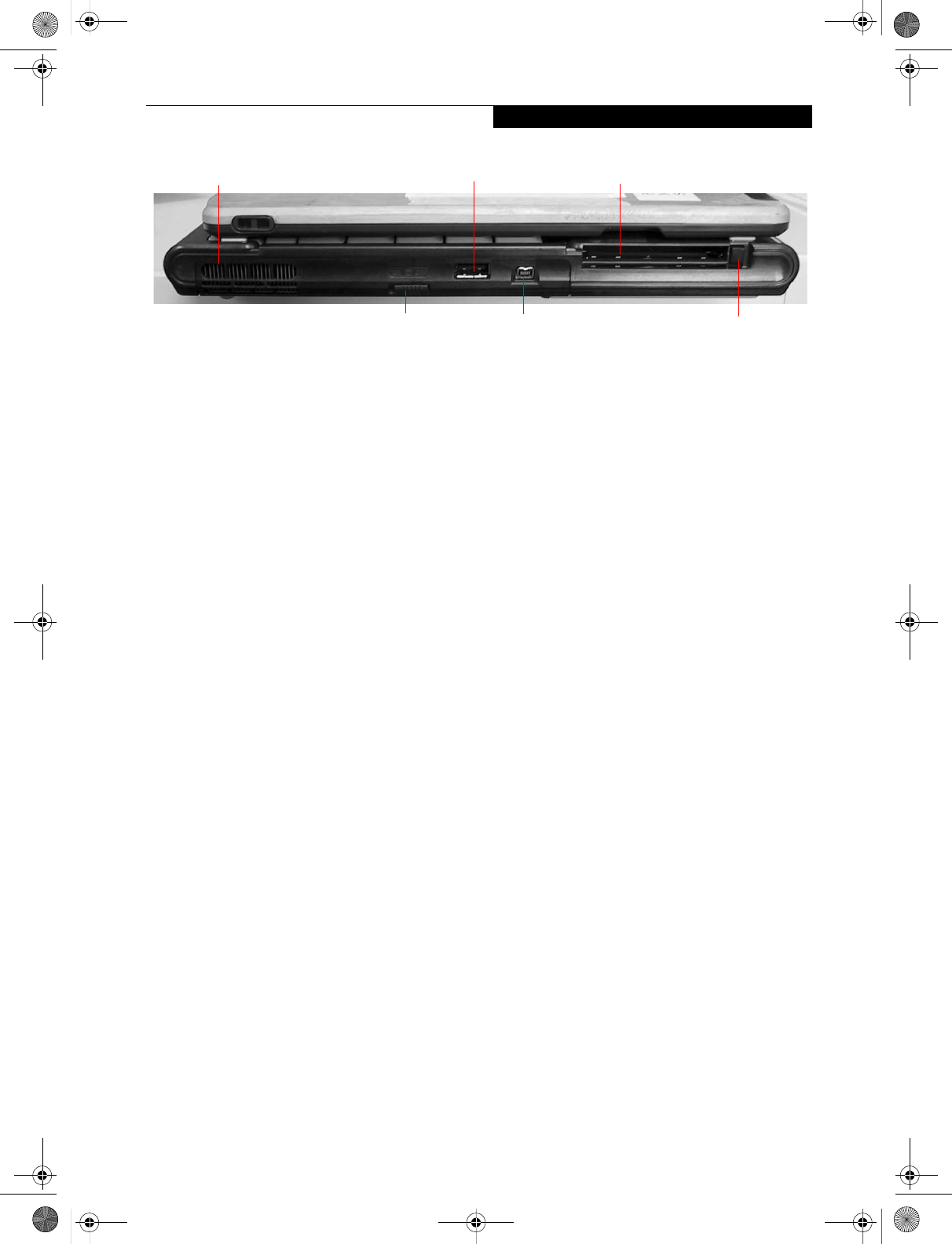
Figure 2-5. LifeBook T Series Tablet PC left-side panel
LEFT-SIDE PANEL COMPONENTS
Following is a brief description of your Tablet PC’s left-
side components. (Figure 2-5)
USB 2.0 Port
The USB 2.0 port allow you to connect Universal Serial
Bus devices. See “Universal Serial Bus Ports” on page 52.
WLAN/Bluetooth On/Off Switch
The wireless LAN/Bluetooth On/Off Switch is used to
power off the wireless antenna when not in use.
IEEE 1394 Jack
Allows you to connect IEEE 1394 (Firewire) peripherals
such as digital video cameras or external hard drives to
your Tablet PC.
PC Card Slot
The PC Card Slot allows you to install a Type I or Type II
PC Card. The PC Card Eject Button is used when
ejecting a PC Card from the slot. See “PC Cards” on
page 47.
PC Card Slot
PC Card Eject/Lock Button
Air Vents
Wireless LAN On/Off Switch
USB 2.0 Port
IEEE 1394 Port
T Series.book Page 13 Wednesday, July 28, 2004 3:35 PM
14
LifeBook T Series Tablet PC - Section 2
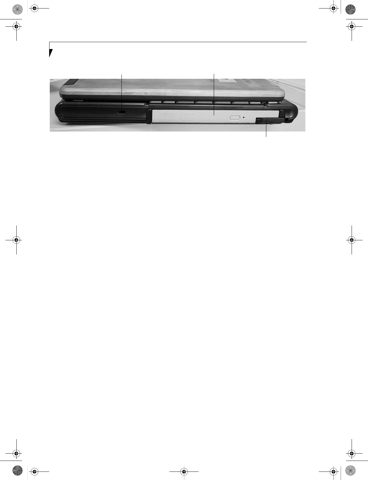
Figure 2-6. LifeBook T Series Tablet PC right-side panel
RIGHT-SIDE PANEL COMPONENTS
Following is a brief description of your Tablet PC’s right-
side components.
Flexible Bay
The Flexible Bay can accommodate one of the following
devices. See “Flexible Bay Devices” on page 18.
■Modular DVD/CD-RW combo drive
■Modular Super-Multi DVD drive
■Modular Lithium ion battery
■Weight Saver
Flexible Bay Eject Lever
The Flexible Bay eject lever releases the Flexible Bay
device.
Anti-theft Lock Slot
The anti-theft lock slot allows you to attach a optional
physical lock-down device.
Flexible Bay Eject Lever
Flexible Bay
Anti-theft Lock Slot
T Series.book Page 14 Wednesday, July 28, 2004 3:35 PM
15
Getting to Know Your Tablet PC
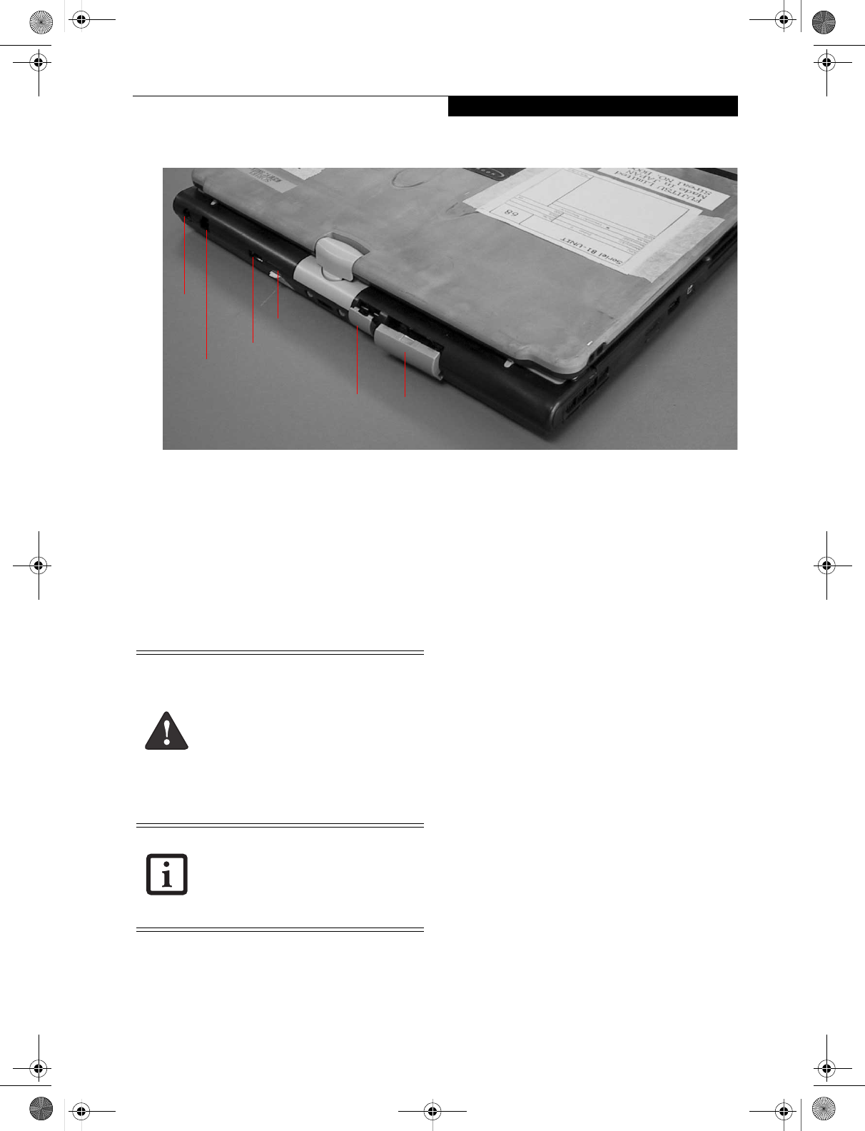
Figure 2-7. LifeBook T Series Tablet PC rear panel
REAR PANEL COMPONENTS
DC Power Jack
The DC power jack allows you to plug in the AC adapter
or the optional Auto/Airline adapter to power your
Tablet PC and charge the internal Lithium ion Battery.
Modem (RJ-11) Telephone Port
The Modem (RJ-11) telephone port is for attaching
a telephone line to the internal multinational 56K
modem.
Infrared Port
The fast IrDA compatible port allows you to communi-
cate with another IrDA-compatible infrared device
without a cable. (See “Infrared Port” on page 52.)
External Monitor Port
The external monitor port allows you to connect an
external VGA or SVGA CRT monitor. Note that when
the optional Port Replicator is attached to the system,
you must use the external monitor port on the Port
Replicator rather than the port on the system. See
“External VGA Monitor Port” on page 53.
USB 2.0 Ports
The two USB 2.0 ports allow you to connect Universal
Serial Bus devices. See “Universal Serial Bus Ports” on
page 52.
LAN (RJ-45) Jack
The internal LAN (RJ-45) port is used for an internal
GigaLAN Ethernet (10/100/1000 Base-T/TX) connec-
tion. See “Internal LAN (RJ-45) jack” on page 52.
DC
External
LAN (RJ-45) Jack
USB 2.0 Port
TBD - NEW GRAPHIC
Power
Jack
Modem (RJ-11) Jack
Monitor Port
Infrared Port
The internal multinational modem is not
intended for use with Digital PBX systems.
Do not connect the internal modem to a
Digital PBX as it may cause serious damage
to the internal modem or your entire
LifeBook T Series Tablet PC. Consult your
PBX manufacturer’s documentation for
details. Some hotels have Digital PBX
systems. Be sure to find out BEFORE you
connect your modem.
The internal modem is designed to the
ITU-T V.90 standard. Its maximum speed
of 53000 bps is the highest allowed by
FCC, and its actual connection rate
depends on the line conditions. The
maximum speed is 33600 bps at upload.
T Series.book Page 15 Wednesday, July 28, 2004 3:35 PM
16
LifeBook T Series Tablet PC - Section 2
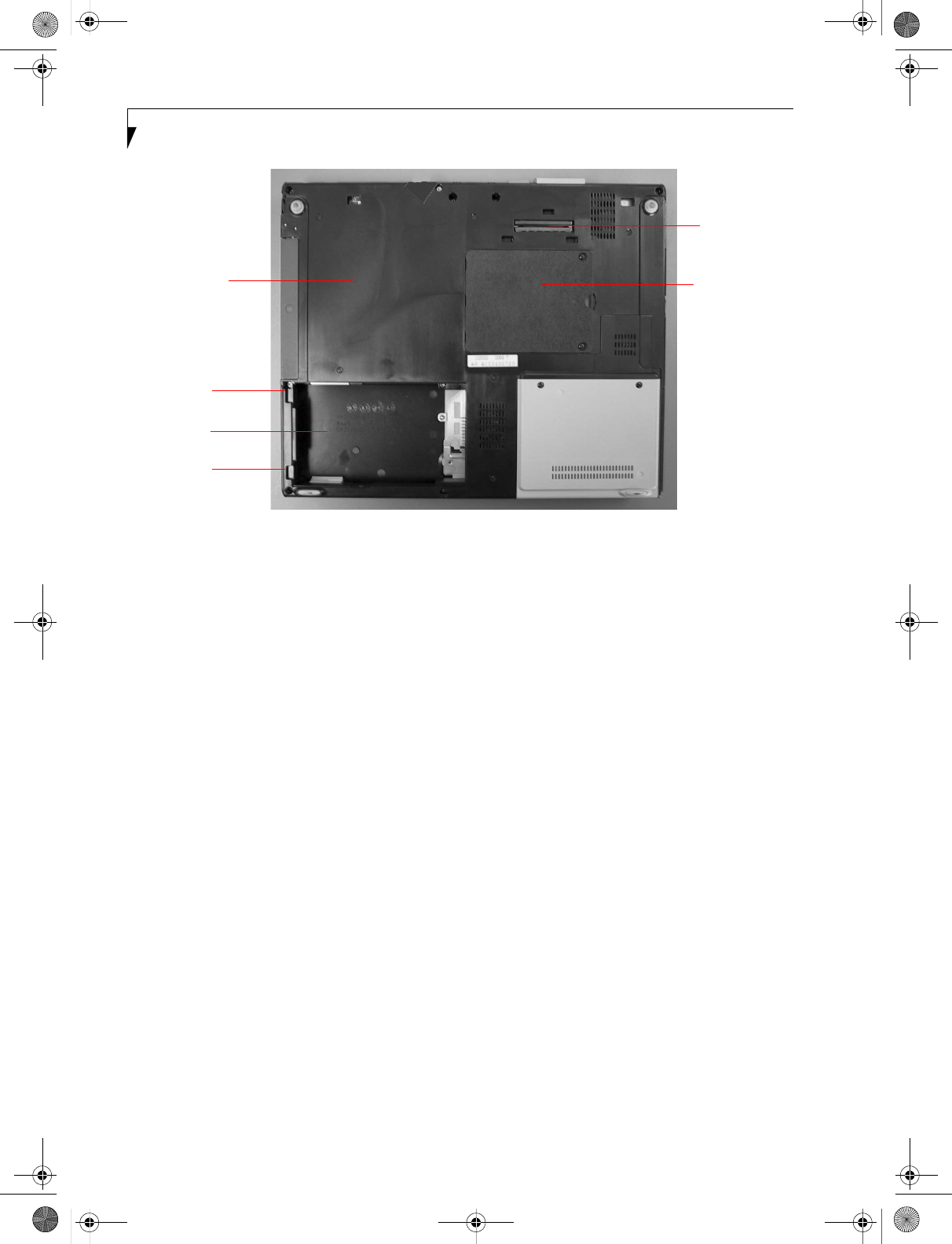
Figure 2-8. LifeBook T Series Tablet PC bottom panel
BOTTOM COMPONENTS
Following is a brief description of your Tablet PC’s
bottom panel components. (Figure 2-8)
Lithium ion Battery Compartment
The battery compartment contains the internal Lithium
ion battery. The battery should be removed when the
computer is stored over a long period of time or for
swapping a discharged battery with a charged Lithium
ion battery. See “Lithium ion Battery” on page 41.
Port Replicator Connector
This connector allows you to connect the optional port
replicator.
Main Unit and Configuration Label
The configuration label shows the model number and
other information about your LifeBook T Series Tablet
PC. In addition, the configuration portion of the label
has the serial number and manufacturer information
that you will need to give your support representative. It
identifies the exact version of various components of
your Tablet PC.
Memory Upgrade Compartment
Your Tablet PC comes with high speed Synchronous
Dynamic RAM (SDRAM). The memory upgrade
compartment allows you to expand the system memory
capacity of your Tablet PC, hence improving overall
performance. See “Memory Upgrade Module” on
page 43.
Memory
Lithium ion
Battery
Main Unit and
Configuration
Label (approximate
Battery
Port Replicator
Connector
location)
Pack
Latch
Battery
Pack
Latch
Compartment
TBD - NEW GRAPHIC
Upgrade
Compartment
T Series.book Page 16 Wednesday, July 28, 2004 3:35 PM
15
Getting to Know Your Tablet PC
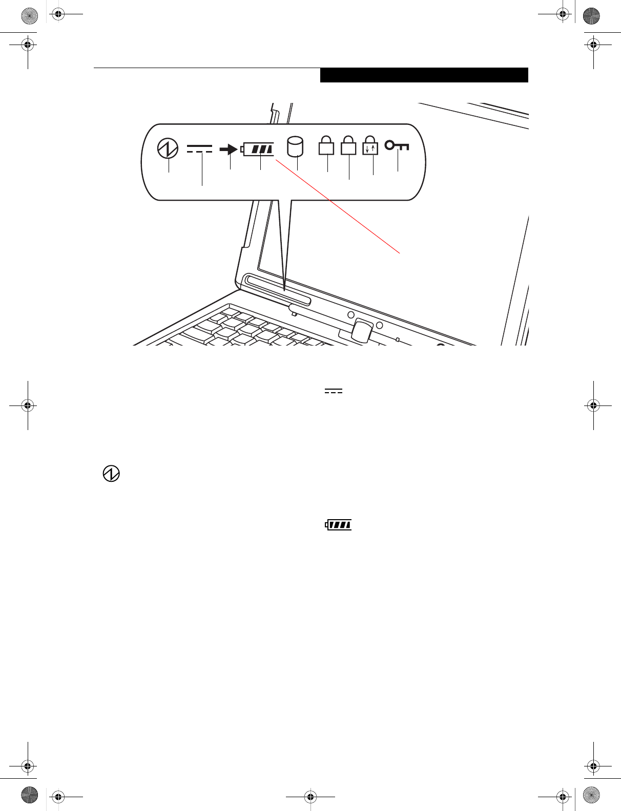
Figure 2-9. Status Indicator Panel
Status Indicator Panel
The Status Indicator Panel displays symbols that corre-
spond to specific components of your LifeBook T Series
Tablet PC. These symbols tell you how each of those
components is operating. (Figure 2-9)
POWER INDICATOR
The Power indicator symbol states whether your system
is operational. It has several different states, each of
which tells you what mode your Tablet PC is in at that
time.
■Steady On: This means that there is power to your
Tablet PC and that it is ready for use.
■Flashing: This means that your Tablet PC is in Standby
mode.
■Steady Off: This means that your system is either in
Hibernate mode, or that your Tablet PC has been
turned off.
If you are charging your battery, the Power indicator
symbol will remain on even if your LifeBook T Series
Tablet PC is shut off. The Power indicator symbol will
also remain on if you have either adapter connected and
are shut down from Windows.
AC ADAPTER INDICATOR
The AC adapter indicator states whether your tablet is
operating from the AC adapter, the auto/airline adapter
or the batteries. This icon has two different states that
can tell you what power source your LifeBook Tablet PC
is using.
■On: This means that either of the adapters are
currently in use.
■Off: Power is only coming from the batteries, and
you do not have an adapter connected.
BATTERY LEVEL INDICATORS
The Battery Level indicators state whether or not the
Lithium ion battery is installed and how much charge is
available within the battery. (Figure 2-10)
Additionally, this indicator displays when an overcur-
rent is detected. If an overcurrent is detected, the battery
stops charging and the Battery Level indicator blinks at
the rate of once per second. To stop the indicator from
blinking, you must disconnect the power adapter.
A1
Battery
Level Hard Drive
Access
Battery
Charging NumLk
ScrLk
Security
Indicator
CapsLk
Power
AC Adapter
NEW GRAPHIC
TBD - Will there be a second battery
indicator for a modular battery?
T Series.book Page 15 Wednesday, July 28, 2004 3:35 PM
16
LifeBook T Series Tablet PC - Section Two
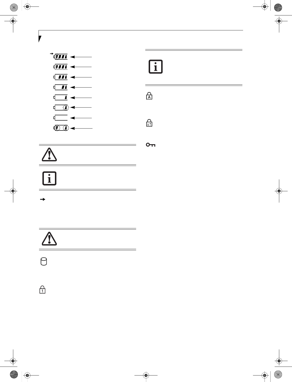
Figure 2-10. Battery Level Indicator
BATTERY CHARGING INDICATOR
Located to the left of the Battery Level indicator is a
small arrow symbol. This symbol states whether the
battery is charging. This indicator will flash if the battery
is too hot or cold to charge.
HARD DRIVE ACCESS INDICATOR
The Hard Drive Access indicator states whether your
internal hard drive is being accessed.
NUMLK INDICATOR
The NumLk indicator states that the integral keyboard is
set in ten-key numeric keypad mode.
If there is no battery activity and the power adapters are
not connected, the Battery Level indicators will also be
off.
CAPSLOCK INDICATOR
The CapsLock indicator states that your keyboard is set
to type in all capital letters.
SCRLK INDICATOR
The ScrLk indicator states that your scroll lock is active.
SECURITY INDICATOR
The Security Indicator flashes (if a password was set)
when the system resumes from Off or Standby modes.
You must enter the password that was set in the Security
Panel before your system will resume operation.
A shorted battery is damaged and must be
replaced. (Figure 2-10)
If there is no battery activity and the
power adapters are not connected, the
Battery Level indicators will also be off.
Batteries subjected to shocks, vibration or
extreme temperatures can be permanently
damaged.
76%–100% Charging
76%–100%
51%–75%
26%–50%
11%–25%
Low Warning <11%
Critical Low or
Dead Battery
Shorted Battery
If you are using the optional external
numerical keypad, pressing the [NumLk]
key will activate the external keypad. The
indicator will come on, however it will not
change any of the functionality of your
keyboard keys.
T Series.book Page 16 Wednesday, July 28, 2004 3:35 PM
17
Getting to Know Your Tablet PC
Figure 2-11. Opening the display
Display Panel
Your LifeBook T Series Tablet PC contains a display
panel that is backlit for easier viewing in bright environ-
ments. The convertible design of your Tablet PC allows
you to open the display fully, rotate it 180 degrees, and
lay it face up on the keyboard. This allows you to use the
system as a tablet, much as you would a pad of paper.
OPENING THE DISPLAY PANEL
1. Press the latch release button. This releases the
locking mechanism. While holding the latch release,
lift display cover.
2. Lift the display backwards, being careful not to
touch the screen, until it is at a comfortable viewing
angle. (Figure 2-11)
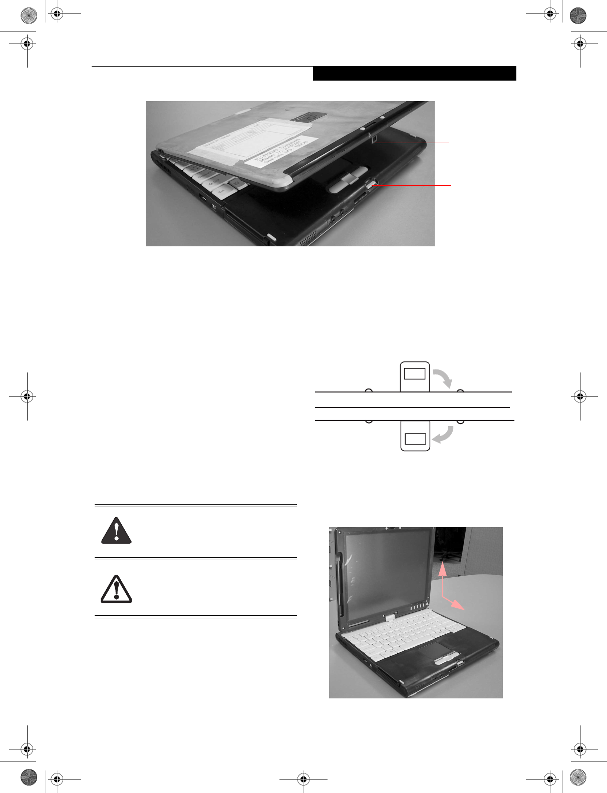
USING THE SYSTEM AS A TABLET
If you would like to use the system as a tablet, perform
the following steps.
1. Lift the display until it is perpendicular to the
keyboard. (Figure 2-13).
2. When the display is perpendicular to the keyboard,
rotate it clockwise (when viewed from the top). Be
very careful to rotate it in the direction indicated.
(Figure 2-14). Turn the display 180 degrees so that it
is facing backwards. (Figure 2-15)
3. Holding the top edge of the display panel, pull it
forward until it is lying nearly atop the keyboard.
4. Push the latch towards the display (See "A" in
Figure 2-12). The latch will pivot so the top latch
disappears, and the bottom latch appears (See "B" in
Figure 2-12). Holding the latch down, lay the display
flush against the system so that the latch engages.
You can now use your system as a tablet. (Figure 2-
16)
Figure 2-12. Latching/Unlatching
5. To return the system to notebook configuration,
repeat step 3 and 2. Be sure to turn the display in the
opposite direction when performing step 2.
Figure 2-13. Fully open display
Display
Panel
Latch
Latch
Release
NEW GRAPHIC
Button
Rotate the system display only in the
direction indicated in the procedure.
Turning the display in the incorrect
direction could cause hinge damage.
In the following step, be sure to position
the display perpendicular to the keyboard,
otherwise the keyboard or display cover
could get scratched.
A
B
Top latch
Bottom latch
Display Side
90
o
T Series.book Page 17 Wednesday, July 28, 2004 3:35 PM