Fujitsu Client Computing WB0011 LifeBook T Seriew with wth (Calexico2 11abg) & BT User Manual T Series
Fujitsu Limited LifeBook T Seriew with wth (Calexico2 11abg) & BT T Series
UserManual.wiki
>
Fujitsu Client Computing
>
WB0011 User Manual
>
user manual part2
Contents
1.
User Manual part1
2.
User manual part2
3.
User manual part3
4.
User manual part4
5.
User manual part5
6.
User manual part1
7.
user manual part2
8.
user manual part3
9.
user manual part4
10.
user manual part5
user manual part2
Navigation menu
Upload a User Manual
Namespaces
Wiki Guide
HTML
PDF
Info
Views
User Manual
Discussion / Help
Navigation
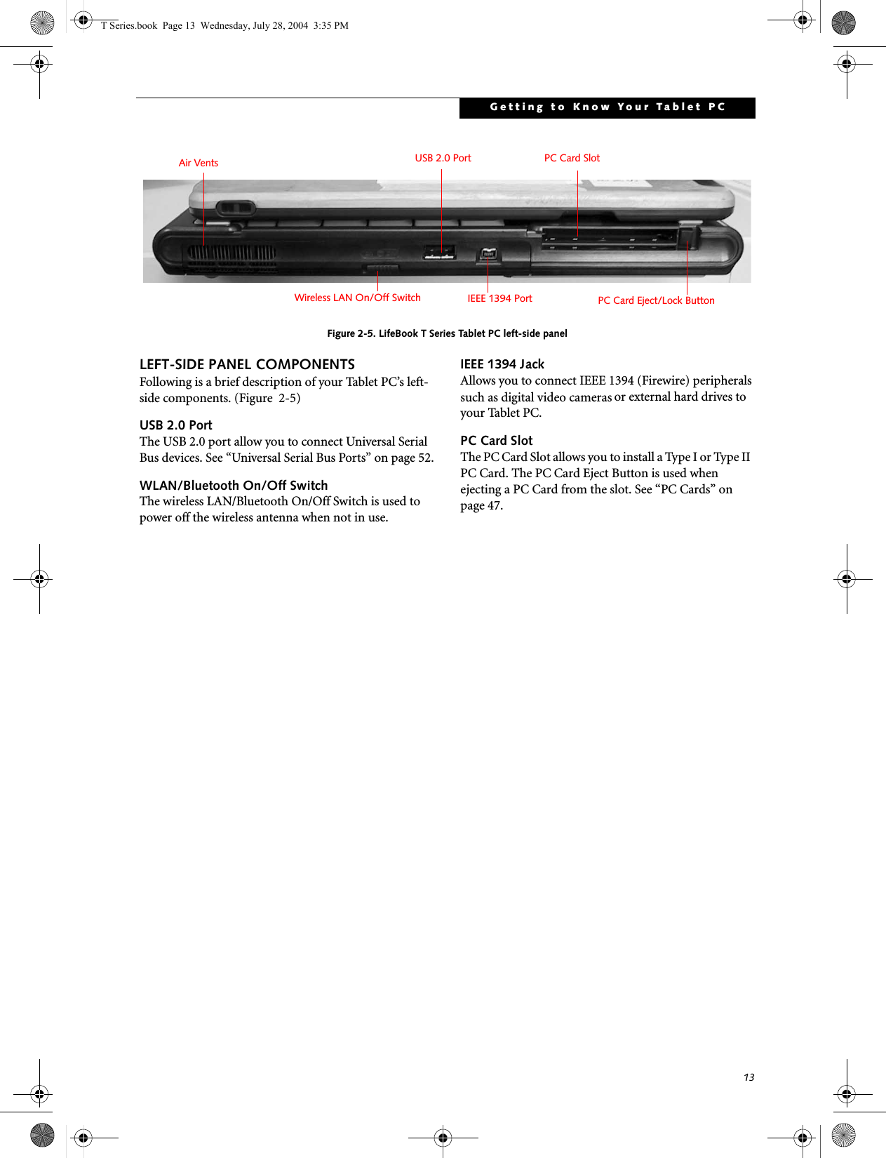
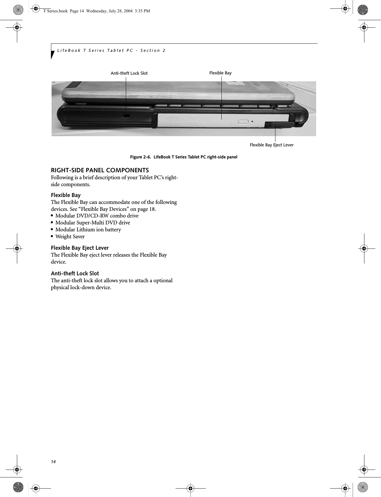
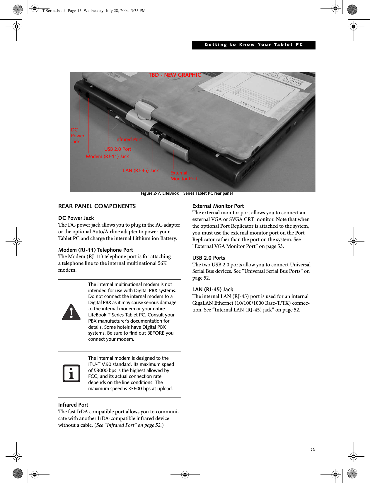
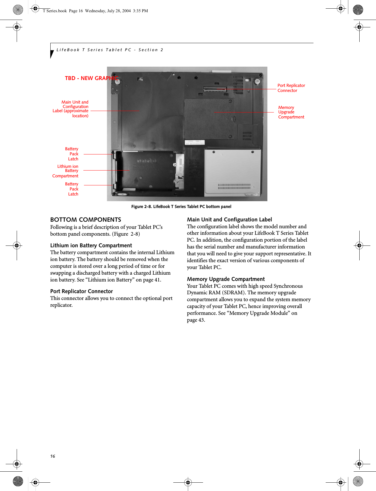
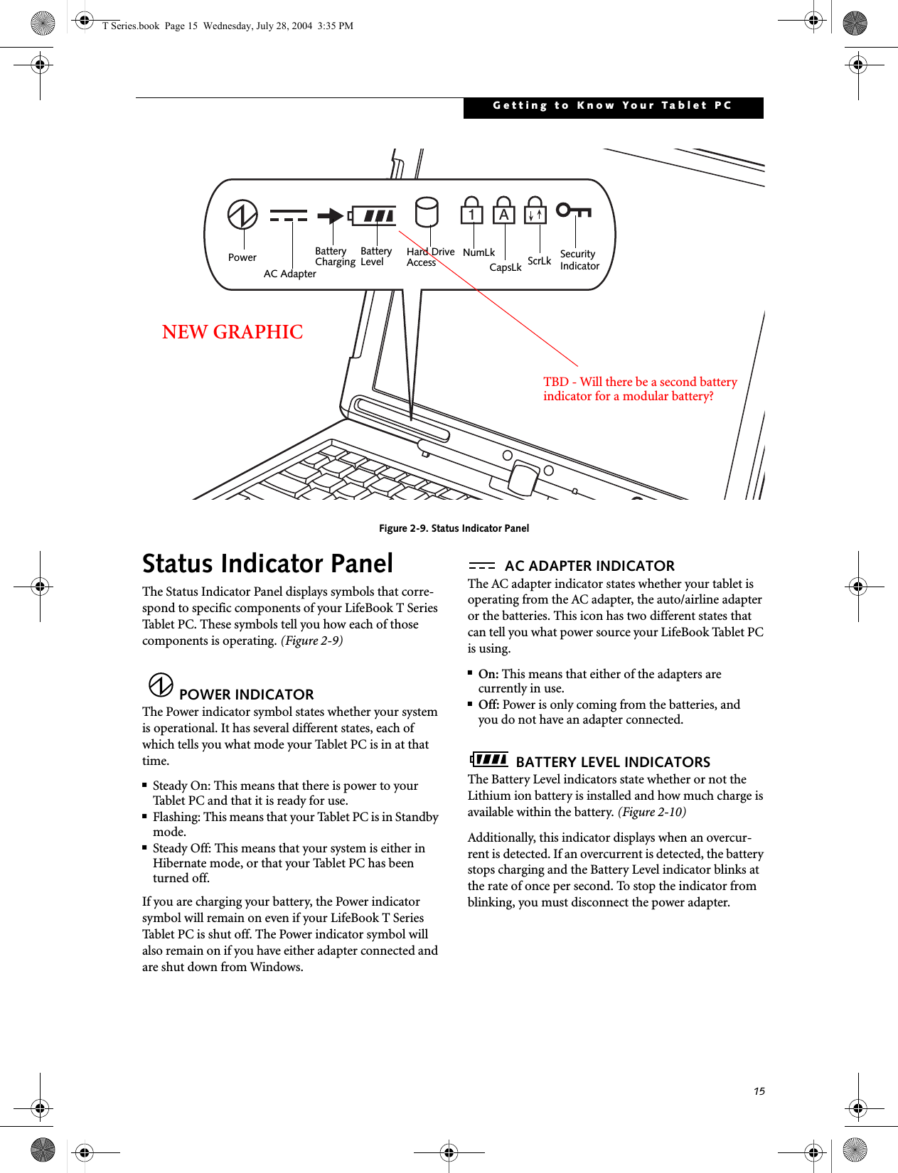
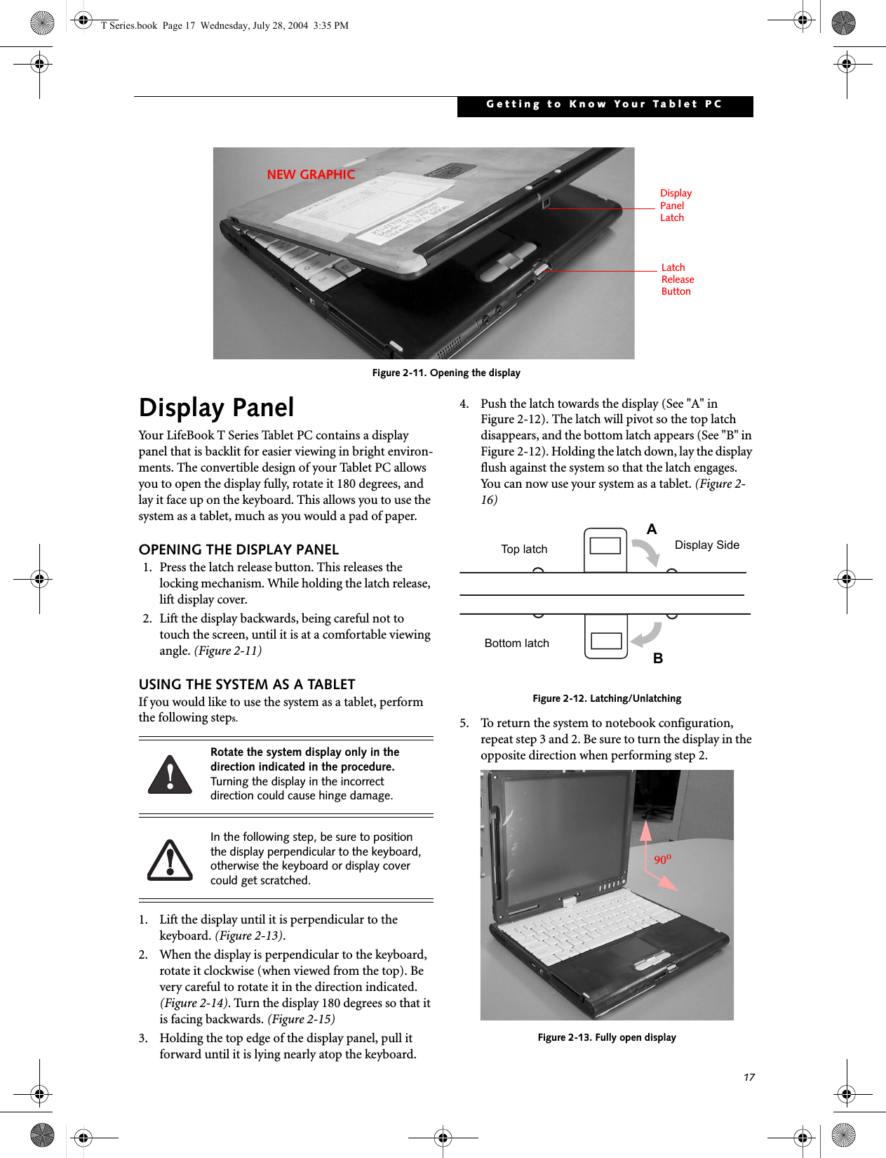
![16LifeBook T Series Tablet PC - Section TwoFigure 2-10. Battery Level IndicatorBATTERY CHARGING INDICATORLocated to the left of the Battery Level indicator is a small arrow symbol. This symbol states whether the battery is charging. This indicator will flash if the battery is too hot or cold to charge.HARD DRIVE ACCESS INDICATORThe Hard Drive Access indicator states whether your internal hard drive is being accessed.NUMLK INDICATORThe NumLk indicator states that the integral keyboard is set in ten-key numeric keypad mode. If there is no battery activity and the power adapters are not connected, the Battery Level indicators will also be off.CAPSLOCK INDICATORThe CapsLock indicator states that your keyboard is set to type in all capital letters. SCRLK INDICATORThe ScrLk indicator states that your scroll lock is active. SECURITY INDICATORThe Security Indicator flashes (if a password was set) when the system resumes from Off or Standby modes. You must enter the password that was set in the Security Panel before your system will resume operation.A shorted battery is damaged and must be replaced. (Figure 2-10) If there is no battery activity and the power adapters are not connected, the Battery Level indicators will also be off.Batteries subjected to shocks, vibration or extreme temperatures can be permanently damaged.76%–100% Charging76%–100%51%–75%26%–50%11%–25%Low Warning <11%Critical Low or Dead BatteryShorted BatteryIf you are using the optional external numerical keypad, pressing the [NumLk] key will activate the external keypad. The indicator will come on, however it will not change any of the functionality of your keyboard keys.T Series.book Page 16 Wednesday, July 28, 2004 3:35 PM](https://usermanual.wiki/Fujitsu-Client-Computing/WB0011.user-manual-part2/User-Guide-465555-Page-6.png)