Fujitsu Client Computing WB0029 LIFEBOOK T SERIES W/ WLL4070 11ABG WLAN & BT User Manual Appendix I 1
Fujitsu Limited LIFEBOOK T SERIES W/ WLL4070 11ABG WLAN & BT Appendix I 1
Contents
- 1. User manual part 1
- 2. User manual part 2
- 3. User manual part 3
- 4. User Manual part 1
User manual part 3


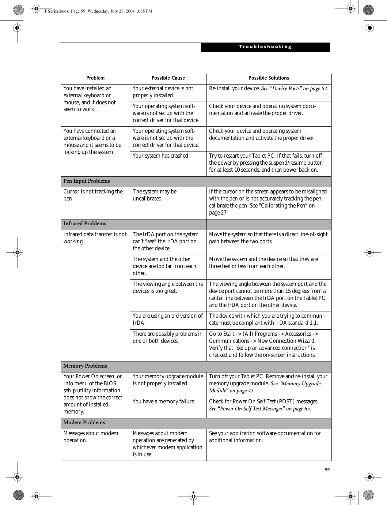
![58LifeBook T Series Tablet PC - Section FiveTROUBLESHOOTING TABLEProblem PageAudio Problems . . . . . . . . . . . . . . . . . . . . . . . . . . page 58Docking Problems . . . . . . . . . . . . . . . . . . . . . . . .page 58Hard Drive Problems. . . . . . . . . . . . . . . . . . . . . . page 58Keyboard or Mouse Problems. . . . . . . . . . . . . . .page 58Pen Input Problems . . . . . . . . . . . . . . . . . . . . . . . page 59Infrared Problems . . . . . . . . . . . . . . . . . . . . . . . . page 59Memory Problems . . . . . . . . . . . . . . . . . . . . . . . . page59Problem PageModem Problems. . . . . . . . . . . . . . . . . . . . . . . . . page 59USB Device Problems . . . . . . . . . . . . . . . . . . . . . page 60PC Card Problems . . . . . . . . . . . . . . . . . . . . . . . . page 60Power Failures . . . . . . . . . . . . . . . . . . . . . . . . . . . page 60Shutdown and Startup Problems . . . . . . . . . . . . page 62Video Problems . . . . . . . . . . . . . . . . . . . . . . . . . . page 63Miscellaneous Problems . . . . . . . . . . . . . . . . . . . page 64Problem Possible Cause Possible SolutionsAudio ProblemsThere is no sound coming from the built-in speakers. The software volume control is set too low. Adjust the sound volume control settings in your software, operating system and applications.Headphones are plugged into your Tablet PC. Plugging in headphones disables the built-in speakers, remove the headphones.Software driver is not config-ured correctly. Refer to your application and operating system documentation for help.Sound could have been muted with function keys. Press [F3] while holding the [Fn] key to toggle the sound on and off.Port Replicator ProblemsTablet PC does not turn on when installed in optional Port ReplicatorPort Replicator AC adapter is not plugged in. Provide power to the Port Replicator.Tablet PC is not properly seated in the Port Replicator. Remove and re-dock your Tablet PC.Hard Drive ProblemsYou cannot access your hard drive. The setup utility is incorrectly set for your internal (Primary Master) hard drive.Revise BIOS settings to set the Primary Mastercorrectly. See “BIOS Setup Utility” on page 34.The wrong drive designator was used by an application when a bootable CD-ROM was used to start the Tablet PC.Verify drive designator used by application is inuse by the operating system. When the operating system is booted from a CD, drive designationsare automatically adjusted. Security is set so your oper-ating system cannot be started without a password.Verify your password and security settings.Keyboard or Mouse ProblemsThe built-in keyboard does not seem to work. The Tablet PC has gone into Standby mode. Push the Suspend/Resume button.Your application has locked out your keyboard. Try to use your integrated pointing device to restart your system. If this fails, turn your Tablet PC off by pressing the suspend/resume button for 10 seconds or more, and then turn it back on.T Series.book Page 58 Wednesday, July 28, 2004 3:35 PM](https://usermanual.wiki/Fujitsu-Client-Computing/WB0029.User-manual-part-3/User-Guide-546104-Page-5.png)
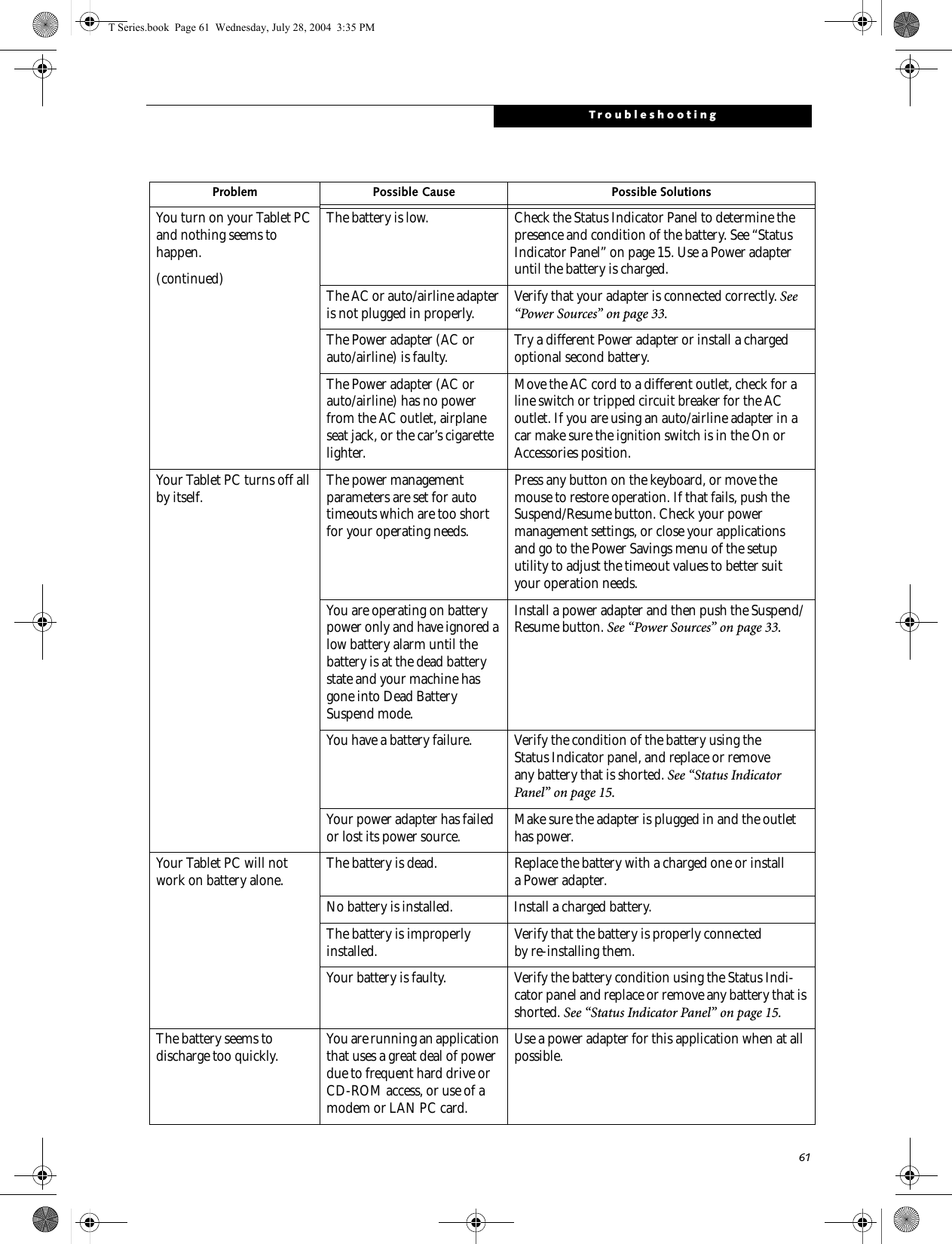
![60LifeBook T Series Tablet PC - Section FiveModem does not appear to work. Modem may not have been intialized. Verify that the modem has been initialized by the operating system. TO do so, right-click on My Computer and select the Hardware tab. Click [Device Manager] and click on the "+" symbol that appears next to Modems. Verify that your device is listed as installed.USB Device ProblemsYou have installed a USB device, but your Tablet PC does not recognize the device, or the device does not seem to work properly.The device is not properly installed. Remove and re-install the device. See “Device Ports” on page 52.The device may have been installed while an application was running, so your Tablet PC is not aware of its installation.Close the application and restart your Tablet PC.Your software may not have the correct software driver active.See your software documentation and activate the correct driver.Your device and another device are assigned the same I/O address.Check all I/O addresses located within the BIOS setup utility and any other installed hardware or software to make sure there are no duplications.PC Card ProblemsA card inserted in the PC Card slot does not work or is locking up the system.The card is not properly installed. Remove and re-install the card. See “PC Cards” on page 47.The card may have been installed while an application was running, so your Tablet PC is not aware of its installation.Close the application and restart your Tablet PC.Your software may not have the correct software driver active.See your software documentation and activate the correct driver.Your PC Card device and another device are assigned the same I/O address.Check all I/O addresses located within the BIOS setup utility and any other installed hardware or software to make sure there are no duplications.Power FailuresYou turn on your Tablet PC and nothing seems to happen.The installed battery is completely discharged or there is no power adapter (AC or Auto/Airline) installed.Check the Status Indicator Panel to determine the presence and condition of the battery. See “Status Indicator Panel” on page 15. Install a charged battery or a Power adapter.The battery is installed but is faulty. Use the Status Indicator Panel to verify the presence and condition of the battery. See “Status Indicator Panel” on page 15. If a battery is indicating a short, remove that battery and operate from another power source or replace that battery.Problem Possible Cause Possible SolutionsT Series.book Page 60 Wednesday, July 28, 2004 3:35 PM](https://usermanual.wiki/Fujitsu-Client-Computing/WB0029.User-manual-part-3/User-Guide-546104-Page-7.png)
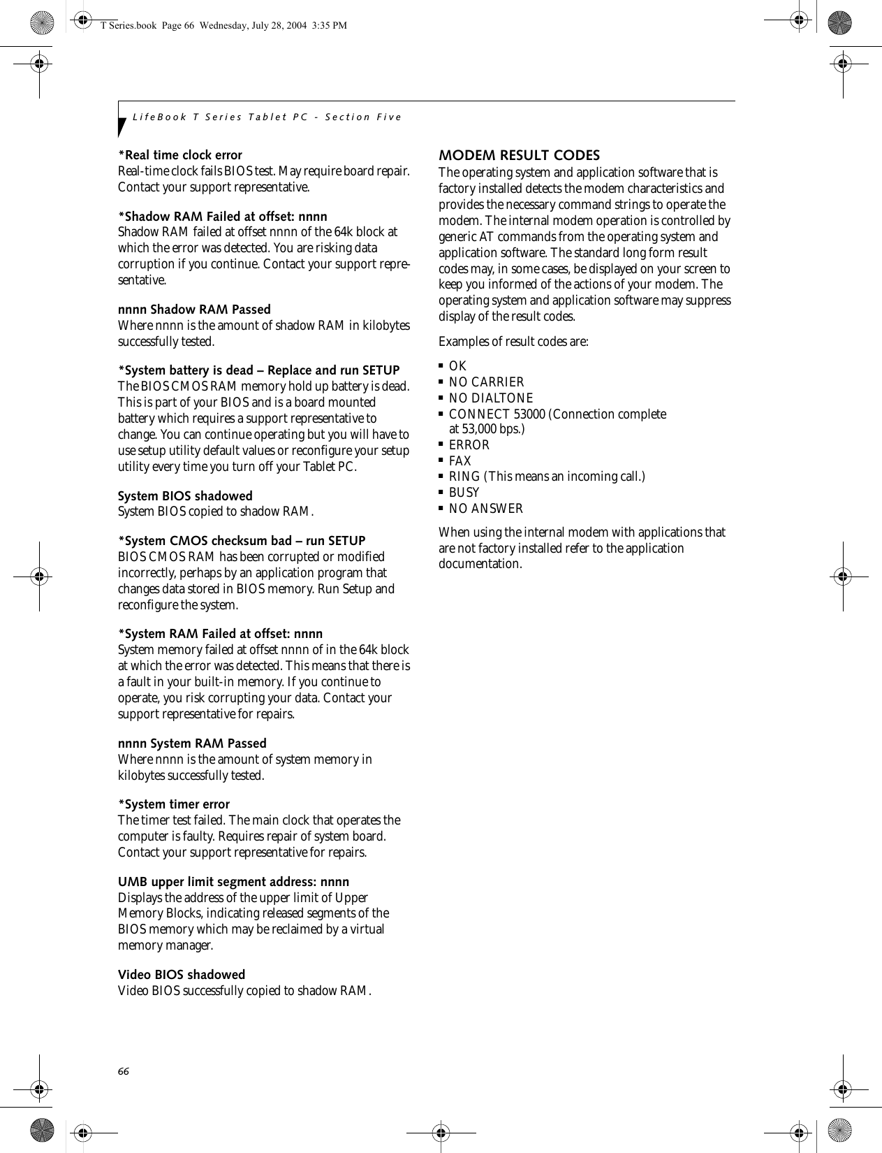
![62LifeBook T Series Tablet PC - Section FiveThe battery seems to discharge too quickly.(continued)The power savings features may be disabled. Check the power management and/or setup utility settings in the Power Savings menu and adjust according to your operating needs.The brightness is turned all the way up. Turn down the brightness adjustment. The higher the brightness the more power your display uses.The battery is very old. Replace the battery.The battery has been exposed to high temperatures. Replace the battery.The battery is too hot or too cold. Restore the Tablet PC to normal operating tempera-ture. The Charging icon on the Status Indicator panel will flash when the battery is outside itsoperating range.The AC Adapter is defective. Replace with another AC Adapter to see if the problem persists. Replace any defective AC Adapters.Shutdown and Startup ProblemsThe Suspend/Resume button does not work. The Suspend/Resume button is disabled from the Advanced submenu of the Power menu of the setup utility. Enable the button from the setup utility.You did not hold the button in long enough. Hold the button longer. This may need to be a few seconds if your application is preventing the CPU from checking for button pushes.There may be a conflict with the application software. Close all applications and try the button again.The system powers up, and displays power-on informa-tion, but fails to load the operating system.The boot sequence settings of the setup utility are not compatible with your configuration.Set the operating source by pressing the [F2] key while the Fujitsu logo is on screen, entering the setup utility and adjusting the source settings from the Boot menu. See “BIOS Setup Utility” on page 34.You have a secured system requiring a password to load your operating system.Make sure you have the right password. Enter the setup utility and verify the Security settings and modify them as accordingly. See “BIOS Setup Utility” on page 34.An error message is displayed on the screen during the Tablet PC boot sequence.Power On Self Test (POST) has detected a problem. See the Power On Self Test (POST) messages to determine the meaning and severity of the problem. Not all messages are errors; some are simply status indicators. See “Power On Self Test Messages” on page 65.Your system display won’t turn on when the system is turned on or when the system has resumed.The system may be password-protected. Check the status indicator panel to verify that the Security icon is blinking. If it is blinking, enter your password.Problem Possible Cause Possible SolutionsT Series.book Page 62 Wednesday, July 28, 2004 3:35 PM](https://usermanual.wiki/Fujitsu-Client-Computing/WB0029.User-manual-part-3/User-Guide-546104-Page-9.png)
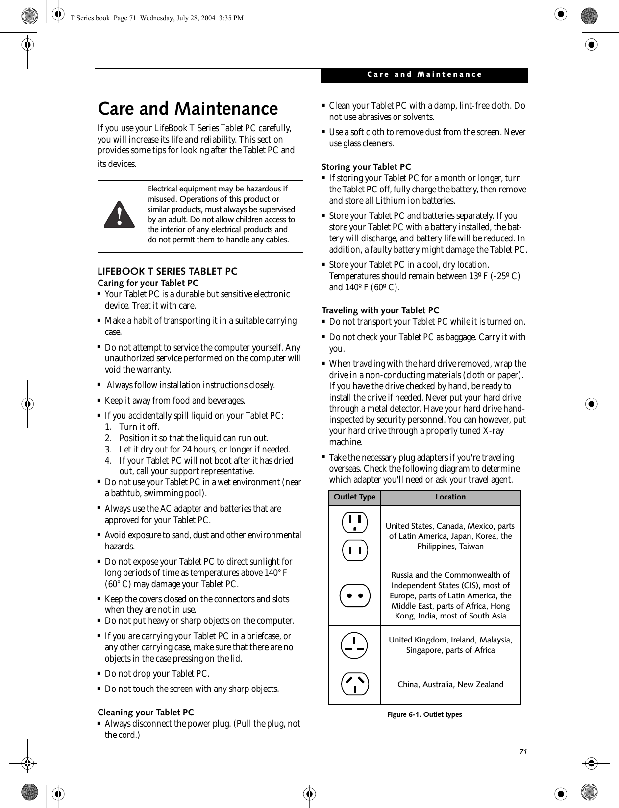
![63TroubleshootingYour Tablet PC appears to change setup parameters when you start it.BIOS setup changes were not saved when you made them and exited the BIOS setup utility returning it to previous settings.Make sure you select Save Changes And Exit when exiting the BIOS setup utility.The BIOS CMOS back-up battery has failed. Contact your support representative for repairs. This is not a user-serviceable part.Video ProblemsThe built-in display is blank when you turn on your Tablet PC.The angle of the display and the brightness settings are not adequate for your lighting conditions.Move the display and the brightness control until you have adequate visibility.The optional Port Replicator is attached, an external monitor is plugged in, and the Tablet PC is set for an external monitor only.Pressing [F10] while holding down the [Fn] key allows you to change your selection of where tosend your display video. Each time you press the combination of keys you will step to the nextchoice. The choices, in order are: built-in display only, external monitor only, both built-in display and external monitor.The power management timeouts may be set for very short intervals and you failed to notice the display come onand go off again.Press any button the keyboard, or move the mouse to restore operation. If that fails, push the Suspend/Resume button. (The display may be shut off by Standy mode, Auto Suspend or Video Timeout)The Tablet PC turned on with a series of beeps and your built-in display is blank.Power On Self Test (POST)has detected a failure which does not allow the displayto operate. Contact your support representative.Your system display won’t turn on when the system is turned on or when the system has resumed.The system may be password-protected. Check the status indicator panel to verify that the Security icon is blinking. If it is blinking, enter your password.The display goes blank by itself after you have been using it.The Tablet PC has gone into Video Timeout, Standby Mode, or Hibernate Mode because you have not used it for a period of time.Press a button on the keyboard, or move the mouse to restore operation. If that fails, push the Suspend/Resume button. Check your power management settings, or close your applications and go to the Power Savings menu of the setup utility to adjust the timeout values to better suit your operation needs. See “BIOS Setup Utility” on page 34.The power management time-outs may be set for very short intervals and you failed to notice the display come onand go off again.Press any button on the keyboard, or move the mouse to restore operation. If that fails, push the Suspend/Resume button. (The display may be shut off by Standby Mode, Auto Suspend or Video Timeout)The display does not close. A foreign object, such as a paper clip, is stuck between the display and the keyboard.Remove all foreign objects from the keyboard.Problem Possible Cause Possible SolutionsT Series.book Page 63 Wednesday, July 28, 2004 3:35 PM](https://usermanual.wiki/Fujitsu-Client-Computing/WB0029.User-manual-part-3/User-Guide-546104-Page-10.png)
![64LifeBook T Series Tablet PC - Section FiveThe display has bright or dark spots. If the spots are very tiny and few in number, this is normal for a large LCD display.This is normal; do nothing.If the spots are numerous or large enough to interfere with your operation needs.The display needs technical diagnosis; contact your support representative.The application display uses only a portion of your screen and is surrounded by a dark frame.You are running an application that does not support 800 x 600/1024 x 768 pixel resolution display and display compres-sion is enabled.When compensation is disabled, a clearer but smaller display for applications that do not support 800 x 600/1024 x 768 pixel resolution will result. You can fill the screen but have less resolution by changing your compensation setting. (See the Video Features submenu, located within the Advanced menu of the BIOS. See “BIOS Setup Utility” on page 34.You have connected an external monitor and it does not display any information.Your BIOS setup is not set to enable your external monitor. Try toggling the video destination by pressing [Fn] and [F10] together, or check your BIOS setup and enable your external monitor. (See the Video Features submenu, located within the Advanced Menu of the BIOS. See “BIOS Setup Utility” on page 34.Your external monitor is not properly installed. Reinstall your device. See “External VGA Monitor Port” on page 53.Your operating system soft-ware is not set up with the correct software driver forthat device. Check your device and operating systemdocumentation and activate the proper driver.You have connected an external monitor and it does not come on.Your external monitor may not be compatible with your Tablet PC.See your monitor documentation and theExternal Monitor Support portions of theSpecifications section. See “Specifications” on page 77.Miscellaneous ProblemsAn error message is displayed on the screen during the operation ofan application.Application software often has its own set of error message displays. See your application manual and help displays screens for more information. Not all messages are errors some may simply be status.Problem Possible Cause Possible SolutionsT Series.book Page 64 Wednesday, July 28, 2004 3:35 PM](https://usermanual.wiki/Fujitsu-Client-Computing/WB0029.User-manual-part-3/User-Guide-546104-Page-11.png)
![65TroubleshootingPOWER ON SELF TEST MESSAGESThe following is an alphabetic list of error-and-status messages that Phoenix BIOS and/or your operating system can generate and an explanation of each message. Error messages are marked with an *. If an error message is displayed that is not in this list, write it down and check your operating system documentation both on screen and in the manual. If you can find no reference to the message and its meaning is not clear, contact your support representative for assistance.nnnn Cache SRAM Passed Where nnnn is the amount of system cache in kilobytes successfully tested by the Power On Self Test. (This can only appear if you have an SRAM PC Card installed.)*Extended RAM Failed at offset: nnnn Extended memory not working or not configured prop-erly. If you have an installed memory upgrade module, verify that the module is properly installed. If it is prop-erly installed, you may want to check your Windows Setup to be sure it is not using unavailable memory until you can contact your support representative.nnnn Extended RAM Passed Where nnnn is the amount of memory in kilobytes successfully tested.*Failing Bits: nnnn The hex number nnnnThis is a map of the bits at the memory address (in System, Extended, or Shadow memory) which failed the memory test. Each 1 (one) in the map indicates a failed bit. This is a serious fault that may cause you to lose data if you continue. Contact your support representative.*Fixed Disk x Failure or Fixed Disk Controller Failure (where x = 1-4) The fixed disk is not working or not configured prop-erly. This may mean that the hard drive type identified in your setup utility does not agree with the type detected by the Power On Self Test. Run the setup utility to check for the hard drive type settings and correct them if necessary. If the settings are OK and the message appears when you restart the system, there may be a serious fault which might cause you to lose data if you continue. Contact your support representative.*Invalid NVRAM media typeProblem with NVRAM access. In the unlikely case that you see this message you may have some display prob-lems. You can continue operating but should contact your support representative for more information.*Keyboard controller error The keyboard controller test failed. You may have to replace your keyboard or keyboard controller but may be able to use an external keyboard until then. Contact your support representative.*Keyboard error Keyboard not working. You may have to replace your keyboard or keyboard controller but may be able touse an external keyboard until then. Contact your support representative.*Keyboard error nn BIOS discovered a stuck key and displays the scan code for the stuck key. You may have to replace your keyboard but may be able to use an external keyboard until then. Contact your support representative.*Operating system not found Operating system cannot be located on either drive A: or drive C: Enter the setup utility and see if both the fixed disk, and drive A: are properly identified and that the boot sequence is set correctly. Unless you have changed your installation greatly, the operating system should be on drive C:. If the setup utility is correctly set, your hard drive may be corrupted and your system may have to be re-installed from your back up media.*Parity Check 1 nnnn Parity error found in the system bus. BIOS attempts to locate the address and display it on the screen. If it cannot locate the address, it displays "????". This is apotentially data destroying failure. Contact yoursupport representative.*Parity Check 2 nnnn Parity error found in the I/O bus. BIOS attempts to locate the address and display it on the screen. If it cannot locate the address, it displays "????". This is apotentially data destroying failure. Contact yoursupport representative.*Press <F1> to resume, <F2> to SETUP Displayed after any recoverable error message. Pressthe [F1] key to continue the boot process or the [F2]key to enter Setup and change any settings.*Previous boot incomplete – Default configuration used Previous Power On Self Test did not complete success-fully. The Power On Self Test will load default values and offer to run Setup. If the previous failure was caused by incorrect values and they are not corrected, the next boot will likely fail also. If using the default settings does not allow you to complete a successful boot sequence, you should turn off the power and contact your support representative.T Series.book Page 65 Wednesday, July 28, 2004 3:35 PM](https://usermanual.wiki/Fujitsu-Client-Computing/WB0029.User-manual-part-3/User-Guide-546104-Page-12.png)
![67TroubleshootingRestoring Your Pre-installed SoftwareThe Drivers and Applications Restore (DAR) DVD contains:■Sets of device drivers and Fujitsu utilities (in specific directories) that are unique to your Tablet PC configu-ration for use as documented below.■Read-me files that provide additional use information for items on this DVD-ROM.RE-INSTALLING INDIVIDUAL DRIVERS AND APPLICATIONS The Drivers and Application DVD can be used to selec-tively re-install drivers and/or applications that may have been un-installed or corrupted. To re-install drivers and/or applications:1. Boot up the system and insert the DAR DVD after Windows has started. A Fujitsu Welcome screen is displayed after the DVD is inserted.2. From the left frame of the Welcome screen, “System Components” and “3rd Party Applications” can be selected. System Components are those drivers and utilities that have been developed by Fujitsu; 3rd Party Applications are applications developed by other vendors.Installing System Components1. To install system components, click on “System Components” in the left frame of the Welcome screen. A list of utilities and drivers will be displayed. Select one or more items from the list, or click [Select All] to select all items in the list. (To de-select your choices, click the [Clear All] button.2. Click [Install Selected Subsystems] to install the selected items.Installing 3rd Party Applications1. To install 3rd party applications, click on “3rd Party Applications” in the left frame of the Welcome screen. A list of applications will be displayed. 2. Select one of the items from the list, and follow the instructions that appear on the screen. Note that only one application may be installed at a time.3. Repeat step 2 to install additional applications.RESTORING THE FACTORY IMAGEThe Restore Disc that came with your system contains two utilities:■The Recovery utility allows you to restore the original contents of the C: drive.■The Hard Disk Data Delete utility on this disc is used to delete all data on your hard disk and prevent it from being reused. Do not use the Hard Disk Data Delete utility unless you are absolutely certain that you want to erase your entire hard disk, including all partitions.BOOT Priority ChangeBefore restoring an image, you must first verify that your system is set up to boot from the DVD drive. To verify/change the boot-up priority (rather than booting-up from the hard drive or an external floppy disk drive), perform the following steps:1. Start your system and press the [F2] key when the Fujitsu logo appears. You will enter the BIOS Setup Utility.2. Using the arrow keys, go to the Boot menu.3. Arrow down to the Boot Device Priority submenu. Press [Enter].4. If “Optical Media Drive” or “CD-ROM Drive” is not at the top of the list, arrow down to the drive in the list, and press the space bar (or the + key) to move it to the top of the list. (The system attempts to boot from the devices in the order in which they are listed.). Note that the BIOS for some systems will indicate “CD-ROM Drive”, even when a DVD drive is connected.5. If you have an external DVD drive connected, proceed to the next step; otherwise, proceed to step 7.6. If you have an external DVD drive connected:• Select the Advanced menu in the BIOS window.In order to install applications and/or drivers from the DAR DVD, you will need to connect an external DVD drive to your system.If you have access to the internet, visit the Fujitsu Support web site at http://us.fujitsu.com/computers to check for the most current information, drivers and hints on how to perform recovery and system updates.• The use of this disc requires that you have a device capable of reading DVDs attached to your system. If you do not have a built-in DVD player, you will need to attach an external player. For more information on available external devices, visit our Web site at: us.fujitsu.com/computers. • This disc can only be used with the system with which it was purchased.T Series.book Page 67 Wednesday, July 28, 2004 3:35 PM](https://usermanual.wiki/Fujitsu-Client-Computing/WB0029.User-manual-part-3/User-Guide-546104-Page-14.png)
![68LifeBook T Series Tablet PC - Section Four• Scroll down to the USB Features submenu and press the Enter key to open it.• If Legacy USB Support is disabled, press the space bar to enable it.• Scroll down to SCSI SubClass Support and press the space bar to enable it. 7. Press [F10], then click on [Yes] to exit the BIOS Setup Utility and return to the boot process.After you have changed the boot priority, you can restore a backup image when you are booting up.Procedure1. Turn on the power to your system.2. Ensure that you have a device that can read DVDs either installed in your system or attached exter-nally to it.3. Insert the Restore Disc into the drive tray.4. Reboot your system.5. After the system reboots, follow the instructions that appear to either restore your system image or erase all data from your hard disk.T Series.book Page 68 Wednesday, July 28, 2004 3:35 PM](https://usermanual.wiki/Fujitsu-Client-Computing/WB0029.User-manual-part-3/User-Guide-546104-Page-15.png)


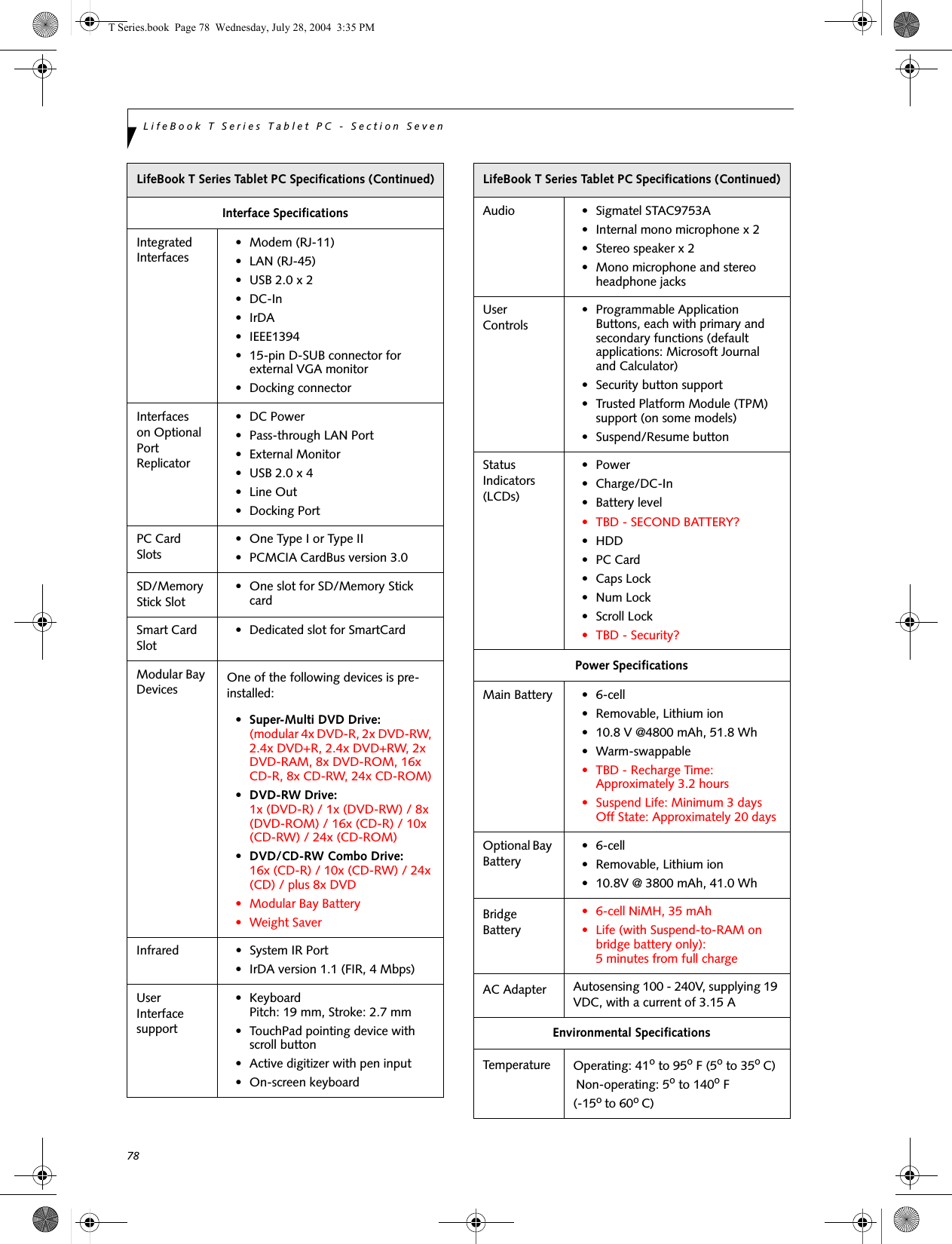


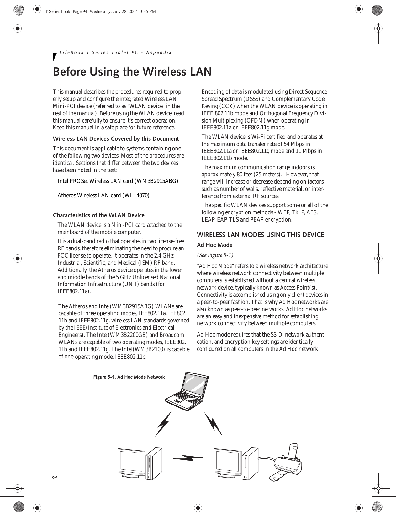
![96LifeBook T Series Tablet PC - AppendixDEACTIVATING THE WLAN DEVICEDeactivation of the WLAN device may be desired in certain circumstances (to extend battery life) or where certain environments require it (e.g., hospitals, clinics, airplanes, etc.). Fujitsu mobile computers employ two methods with which to deactivate the WLAN device, 1) the Wireless On/Off Switch and 2) in Windows using the Intel PROSet, Atheros Client Utility, or Broadcom Wireless Utility software.Deactivation using the Wireless On/Off SwitchThe WLAN device can be deactivated quickly and effi-ciently by toggling the Wireless On/Off Switch to the Off position. (Figure 5-3)The Wireless On/Off switch has no effect on non-Wire-less LAN models.Figure 5-3. Wireless LAN On/Off Switch LocationDeactivation using the Intel PROSet SoftwareThe WLAN device can also be deactivated in Windows using the Intel PROSet Software. The procedure to accomplish this:1. Click [Start]-> [Control Panel].2. If the Control Panel is in Category view, switch to Classic view by clicking "Switch to Classic View" which can be found in the left frame of the Control Panel window. 3. Click on the Intel PROSet for Wireless icon which will execute the Intel PROSet application.4. Select the General tab if it is not already selected.5. Check the Off radio button next to "Switch radio:" then click the [OK] button. Deactivation using Atheros Client Utility software1. Click [Start] -> [Program Files] -> [Atheros] -> Atheros Client Utility.2. Choose Action and click Disable Radio.Deactivation using Broadcom Wireless Utility1. Click [Start] --> [Control Panel] --> [Broadcom Wireless Utility]. The Broadcom Wireless Configu-ration Utility window will be displayed.2. Click the Wireless Networks tab.Click the [Enable Radio] box to clear it, then click the [OK] button. Wireless communications on/off switching will be deactivated and the transmission of radio waves from the wireless LAN will be stoppedACTIVATING THE WLAN DEVICEActivation of the WLAN device can be accomplished using the same methods as the deactivation process■Using the Wireless On/Off Switch■In Windows using the Intel PROSet, Atheros, or Broadcom software.Wireless LANOn/Off SwitchTBD - NEW GRAPHICT Series.book Page 96 Wednesday, July 28, 2004 3:35 PM](https://usermanual.wiki/Fujitsu-Client-Computing/WB0029.User-manual-part-3/User-Guide-546104-Page-43.png)
![97WIreless LAN User’s Guide Configuration of the WLAN DeviceThe WLAN Device can be configured to establish wire-less network connectivity using one of the following tools:■Windows XP Wireless Zero Configuration (WZC) - The WZC allows for multiple profile setup and sup-port for most industry standard security solutions. This configuration should be used for the Broadcom WLAN device.■Intel PROSet Software - The Intel PROSet Software allows for multiple profile setup and supports auto-matic profile switching. Support for most industry standard security solutions as well as Cisco Compati-ble Extensions (CCX) is contained in this software.■Atheros Client Utility - The Atheros Client Utility soft-ware allows for multiple profile setups and supports automatic profile switching. Support for most indus-try standard security solutions, as well as Cisco Com-patible Extensions (CCX), is contained in this software.FLOW OF OPERATIONS1. Activate the WLAN Device (See Activating the WLAN Device on page 96 for more information).2. Configure the Wireless Network parameters (See Configure Wireless Network Parameters on page 98 for more information).■Enter the network name (SSID)■Choose the appropriate WLAN architecture (Ad Hoc or Infrastructure)■Choose Authentication method: Open, Shared, WPA, or WPA-PSK■If using static WEP keys, enter static WEP key and choose key index. 3. Configure network settings (See Configure Net-work Parameters on page 98 for more information)■TCP/IP settings■Workgroup or Domain settings.CONFIGURATION USING WIRELESS ZERO CONFIGURATION TOOLThis section explains the procedure to properly configure the WLAN device using the WZC. Pre-defined parameters will be required for this procedure. Please consult with your network administrator for these parameters:Network Name - Also known as the SSIDNetwork Key (WEP) - Required if using static WEP keys. Authentication Type - Open, Shared, WPA, or WPA-PSKProcedure1. Activate the WLAN device using the Wireless On/Off Switch, the Intel PROSet software, or the Atheros Client Utility.2. Click the [Start] button first and then [Control Panel].3. If the Control Panel is in Category view, switch to Classic view by clicking "Switch to Classic View" which can be found in the left frame of the Control Panel window. 4. Double-click the Network Connections icon. A list of previously configured networks will be dis-played. 5. Right-click [Wireless Network Connection] in the list, and then click [Properties] in the menu dis-played.6. Click the [Wireless Networks] tab.7. Click [Refresh], then choose the correct SSID from the [Available Networks] window. Click [Config-ure] and proceed to step 8. Please note that only wireless networks that broadcast their SSID will be displayed. If the SSID of the wireless network is not visible, you must manually add it. This can be accomplished by clicking [Add]8. From within the Association tab configure the appropriate WLAN parameters. Please have ready the following parameters:■Network name (SSID) - ASCII string of up to 33 characters used by the WLAN to logically separate wireless networks. ■Authentication Type - Options include Open, Shared, WPA, or WPA-PSK■Network Key - If Authentication Type is Open or Shared, choices are None or WEP. If Authentica-tion Type is WPA or WPA-PSK, choices are WEP or TKIP.Ad Hoc Networks: All computers in an Ad Hoc network must be assigned with the same SSID and T Series.book Page 97 Wednesday, July 28, 2004 3:35 PM](https://usermanual.wiki/Fujitsu-Client-Computing/WB0029.User-manual-part-3/User-Guide-546104-Page-44.png)
![98LifeBook T Series Tablet PC - Appendixthe checkbox for the field [This is a computer to computer (ad hoc) network, wireless access points are not used.] must be checked.Access Point (Infrastructure) Networks: The SSID must be identical to the SSID of the access point(s) and the checkbox for the following field must be unchecked [This is a computer to computer (ad hoc) network wireless access points are not used.] Refer to the access point manual, or contact your network administrator9. Configure Wireless Network Key parameters (Net-work Authentication and Encryption).a. Choose the Network Authentication method appropriate for your wireless LAN. Options include Open, Shared, WPA, and WPA-PSK.Ad Hoc Networks: Network Authentication settings must be identical for all computers in the Ad Hoc network. Access Point (Infrastructure Networks): Network Authentication setting must be config-ured to match the setting of the Access Point(s). Please contact your network administrator for this information.b. Choose the Encryption method appropriate for your wireless LAN. Options for Open or Shared Authentication are None or WEP. Options for WPA or WPA-PSK are WEP or TKIP.c. If using static WEP keys, clear the check mark from the [The key is provided for me automati-cally] check box. If using an authentication method that uses dynamic WEP (e.g., WPA, WPA-PSK, 802.1x/EAP), the check box should remain checked. Please contact your network administrator for the correct settings.d. Static WEP keys (if applicable) are entered in the [Network Key] box. Configuration of the [Network Key] is not required if the [The key is provided for me automatically] check box is checked.■Static WEP keys entered in ASCII code format will be either five characters (40-bit) or thirteen characters (104-bit) in length. Valid characters are 0 - 9, A - Z.■Static WEP keys entered in hexadecimal code format will be either ten characters (40-bit) or twenty-six characters (104-bit) in length. Valid characters are 0 - 9, A - F.Ad Hoc Networks: Assign the same net-work key to all the personal computers to be connected.Access Point (Infrastructure) Networks: Assign the identical network key that is programmed into the access point. Please contact your network administrator for this information.e. If using static WEP keys, confirm the Network key by re-entering the same data in the [Confirm network key:] field.f. The Key index used must be identical to the transmit key used in the Access Point or other wireless device. This is only applicable when static WEP keys are used. Please contact your network administrator for this information.10. Access Point (Infrastructure) Networks Only: If the wireless network you are establishing connec-tivity to implements an access control security mechanism, configuration of 802.1x parameters may be necessary. Please contact your network administrator for these settings. Configuration of these parameters is not applicable to home users. 11. Click [OK] to close the [Wireless Network] window which will cause the WLAN device to re-establish wireless network connectivity using the recently configured parameters.CONFIGURATION USING INTEL PROSET SOFTWAREThis section explains the procedure to properly configure the WLAN device using the Intel PROSet Soft-ware. Pre-defined parameters will be required for this procedure. Please consult with your network adminis-trator for these parameters:Network Name - Also known as the SSIDNetwork Key (WEP) - Required if using static WEP keys. Authentication Type - Open, Shared, WPA, or WPA-PSKProcedure1. Activate the WLAN device using either the Wireless On/Off Switch or the Intel PROSet software.2. Click the [Start] button first and then [Control Panel].3. If the Control Panel is in Category view, switch to Classic view by clicking "Switch to Classic View" which can be found in the left frame of the Control Panel window. 4. Double-click the icon [Intel PROSet] to execute the Intel PROSet Software.5. From the General page, click the Networks tab. T Series.book Page 98 Wednesday, July 28, 2004 3:35 PM](https://usermanual.wiki/Fujitsu-Client-Computing/WB0029.User-manual-part-3/User-Guide-546104-Page-45.png)
![99WIreless LAN User’s Guide 6. Click the [Add] button. The General Settings dialog displays. 7. From the General page, click the Networks tab. 8. Click the [Add] button. The General Settings dialog displays. 9. Enter a profile name in the Profile Name field. 10. Enter the network SSID, in the Network Name (SSID) field. 11. Click Infrastructure or Ad Hoc for the operating mode. 12. The Mandatory AP option is only used if Infra-structure mode is selected. Use this option to con-nect to a specific access point. Click the Mandatory AP button, enter the MAC address for the access point. Click OK to save the setting and return to the General Settings page. 13. If you are using Cisco CCX, click the Enable Cisco Client eXtentions option to enable Cisco CKIP data encryption on the Security Settings page. If you have checked the Cisco's "Mixed-Cell" box in the Advanced Setting, this option must also be checked. 14. Click Next.15. Click the Security tab16. Select Open, Shared, WPA, or WPA-PSK in the Network Authentication options. 17. Select either None, WEP, CKIP (if Enable Cisco Cli-ent eXtentions is enabled on the General Settings page), or TKIP for the data encryption. 18. If WEP is selected, select either 64 or 128-bit for the Encryption Level. 19. Select the key index 1, 2, 3 or 4. 20. Enter the WEP key if required. If your network does not employ a 802.1x/EAP security mechanism, please skip to step 24.21. Click the 802.1x Enabled checkbox to enable the 802.1x security option. Please contact your network administrator if configuration of this setting is required.22. Select the appropriate 802.1x/EAP Type. Please contact your network administrator if configura-tion of this setting is required.23. After selecting your authentication type, click the Configure button to open the Settings dialog. Enter the user name and password of the user you have created on the authentication server. The user name and password do not have to be the same as name and password of your current Windows user login. The "Server Identity" can be use the default setting. The "Client Certificate" should be the one obtained from your RADIUS server or other certifi-cation server. 24. Click Close to save the settings. 25. From the General settings page, click the new pro-file name shown in the Profile List. Use the up and down arrows to position the priority of the new profile in the priority list. 26. Click the Advanced button to set the network con-nection preferences. 27. Click the Connect button to connect to the net-work. 28. Click OK to close the Intel(R) PROSet for Wireless utilityCONFIGURATION USING ATHEROS CLIENT UTILITY SOFTWAREThis section explains the procedure to properly configure the WLAN device using the Atheros Client Utility. Pre-defined parameters will be required for this procedure. Please consult with your network adminis-trator for these parameters:Network Name - Also known as the SSIDNetwork Key (WEP) - Required if using static WEP keys. Authentication Type - Open, Shared, WPA, or WPA-PSKProcedure1. Activate the WLAN device using either the Wireless On/Off Switch or the Atheros Client Utility2. Click the [Start] button first and then [Control Panel].3. If the Control Panel is in Category view, switch to Classic view by clicking "Switch to Classic View" which can be found in the left frame of the Control Panel window. 4. Double-click the icon [Atheros Client Utility] to execute the Atheros Client Utility.5. From the Current Status page, click the Profile Management tab. 6. If this is your first time using this utility, highlight the profile [Default] and Click the [Modify] button, otherwise Click the [New] button. The General Set-tings dialog displays. 7. From the General page, enter a profile name in the Profile Name field. T Series.book Page 99 Wednesday, July 28, 2004 3:35 PM](https://usermanual.wiki/Fujitsu-Client-Computing/WB0029.User-manual-part-3/User-Guide-546104-Page-46.png)
![101WIreless LAN User’s Guide CONNECTION TO THE NETWORKThis section explains connection to the network.If there is an administrator of the network, contact the network administrator for data settings.Setting the networkPerform the “Setting TCP/IP” and “Confirming the computer and work group names” operations required for network connection.Setting TCP/IP1. Click the [Start] button first and then [Control Panel].2. If the Control Panel is in Category view, switch to Classic view by clicking “Switch to Classic View” under Control Panel the left frame. (If you are already in Classic view, “Switch to Category View” will be displayed.) 3. Double-click [Network Connections]. A list of cur-rently installed networks will be displayed.4. Right-click [Wireless Network Connection] in the list, and then click [Properties] in the menu dis-played. The [Wireless Network Connection Proper-ties] window will be displayed.5. Click the [General] tab if it is not already selected.6. Click [Internet Protocol (TCP/IP] and then click [Properties]. The [Internet Protocol (TCP/IP) Properties] window will be displayed.7. Set the IP address as follows:■For ad hoc connection: Select [Use the following IP address:] and then enter data for [IP address] and [Subnet mask]. See page 107 for IP address setting.■For access point (infrastructure) connection: If your network uses DHCP, select [Obtain an IP address automatically] and [Obtain DNS server address automatically]. If your network uses static IP addresses, consult with your network adminis-trator for the correct IP address settings.8. Click the [OK] button. Processing will return to the [Wireless Network Connection Properties] window.9. Click the [OK] button.10. Close the [Network Connection] window. Following this operation, confirm the names of the computer and the workgroup as follows.Confirming the computer and work group names1. Click the [Start] button, then [Control Panel].2. If the Control Panel is in Category view, switch to Classic view by clicking “Switch to Classic View” under Control Panel the left frame. (If you are already in Classic view, “Switch to Category View” will be displayed.) 3. Double-click the [System] icon. The [System Prop-erties] window will be displayed.4. Click the [Computer Name] tab.5. Confirm the settings of [Full computer name:] and [Workgroup:].a. The setting of [Full computer name:] denotes the name for identifying the computer. Any name can be assigned for each personal computer. Enter the desired name in less than 15 ASCII character code format. Identifiability can be enhanced by entering the model number, the user name, and other factors.b. [Workgroup name] is the group name of the network. Enter the desired name in less than 15 ASCII character code format.For ad hoc connection: Assign the same network name to all personal computers existing on the network.For access point (infrastructure) connection: Assign the name of the work group to be accessed.6. Click the [OK] button. If a message is displayed that requests you to restart the personal computer, click [Yes] to restart the computer.Setting the sharing functionSet the sharing function to make file and/or printer sharing with other network-connected personal computers valid.This operation is not required unless the sharing func-tion is to be used.To change the setting of the IP address, you need to be logged in from Windows as an administrator.To modify the computer name and/or the work group name, you need to be logged in from Windows as an administrator.To change the name, click [Change] and then proceed in accordance with the instruction messages displayed on the screen.T Series.book Page 101 Wednesday, July 28, 2004 3:35 PM](https://usermanual.wiki/Fujitsu-Client-Computing/WB0029.User-manual-part-3/User-Guide-546104-Page-48.png)
![102LifeBook T Series Tablet PC - AppendixThe folder and printer for which the sharing function has been set will be usable from any personal computer present on the network.Setting the Microsoft network-sharing service1. Click the [Start] button first and then [Control Panel]. 2. If the Control Panel is in Category view, switch to Classic view by clicking “Switch to Classic View” under Control Panel the left frame. (If you are already in Classic view, “Switch to Category View” will be displayed.) 3. Double-click [Network Connections]. A list of cur-rently installed networks will be displayed.4. Right-click [Wireless Network Connection] in the list, and then click [Properties] in the menu dis-played. The [Wireless Network Connection Proper-ties] window will be displayed.5. If [File and Printer Sharing for Microsoft Net-works] is displayed, proceed to step 6. If [File and Printer Sharing for Microsoft Networks] is not dis-played, skip to step 7.6. Make sure that the [File and Printer Sharing for Microsoft Networks] check box is checked, and then click the [OK] button. Skip to “Setting file-sharing function”.7. Click [Install]. The [Select Network Component Type] window will be displayed.8. Click [Service], then click the [Add] button. The [Select Network Service] window will be displayed.9. Click [File and Printer Sharing for Microsoft Net-works] and then click the [OK] button. Processing will return to the [Wireless Network Connection Properties] window, and [File and Printer Sharing for Microsoft Networks] will be added to the list.10. Click the [Close] button.Setting the file-sharing functionThe procedure for setting the file-sharing function follows, with the “work” folder in drive C: as an example.1. Click the [Start] button first and then [My Com-puter]. 2. Double-click [Local disk (C:)].3. Right-click the “work” folder (or whichever folder you want to share), and then click [Sharing and Security...] in the menu displayed. The [Folder Name Properties] window will be displayed.4. Click [Sharing] if it isn’t already selected.5. Click the link stating “If you understand the secu-rity risks, but want to share files without running the wizard, click here”.6. Click “Just enable file sharing” and click [OK].7. Check the [Share this folder on the network] check box.8. Click the [OK] button. The folder will be set as a sharable folder, and the display of the icon for the “work.” folder will change.Setting the printer-sharing function1. Click the [Start] button first and then [Printers and FAX]. A list of connected printers will be displayed.2. Right-click the printer for which the sharing func-tion is to be set, and then click [Sharing] in the menu displayed. The property window correspond-ing to the selected printer will be displayed.To share a file and/or the connected printer, you need to be logged in as an administrator. Setting the file-sharing function for the file which has been used to execute Network Setup Wizard is suggested on the screen. For the wireless LAN, however, since security is guaranteed by entry of the network name (SSID) and the network key, the steps to be taken to set the file-sharing function easily without using Network Setup Wizard are given below.To specify the corresponding folder as a read-only folder, select the [Read only] checkbox under the General tab.Setting the printer-sharing function when Network Setup Wizard has been executed is suggested on the screen. For the wireless LAN, however, since security is guaranteed by entry of the network name (SSID) and the network key, the steps to be taken to set the printer-sharing function without using Network Setup Wizard are laid down below.T Series.book Page 102 Wednesday, July 28, 2004 3:35 PM](https://usermanual.wiki/Fujitsu-Client-Computing/WB0029.User-manual-part-3/User-Guide-546104-Page-49.png)
![103WIreless LAN User’s Guide 3. Click the [Sharing] tab.4. Click [Share this printer].5. Enter the sharing printer name in [Share name].6. Click the [OK] button. Confirming connectionAfter you have finished the network setup operations, access the folder whose sharing has been set for other personal computers. Also, confirm the status of the radio waves in case of trouble such as a network connection failure.Connecting your personal computer to another personal computer1. Click [Start] first and then [My Computer]. The [My Computer] window will be displayed in the left frame.2. Click [My Network Places] in the “Other Places” list. The window [My Network Places] will be dis-played.3. Click [View workgroup computers] under Network Tasks in the left frame.4. Double-click the personal computer to which your personal computer is to be connected. The folder that was specified in “Setting the file-sharing func-tion” on page 102 will be displayed.5. Double-click the folder to be accessed.In the case of access point (infrastructure) connection, enter the necessary data for the access point before confirming connection. Refer to the manual of the access point for the access point setup procedure.T Series.book Page 103 Wednesday, July 28, 2004 3:35 PM](https://usermanual.wiki/Fujitsu-Client-Computing/WB0029.User-manual-part-3/User-Guide-546104-Page-50.png)
![107WIreless LAN User’s Guide IP address informationIf IP address is unknown, set IP address as follows:If you have an access point (DHCP server) on the network, set the IP address as follows:[Obtain an IP address automatically]If the IP address is already assigned to the computer in the network, ask the network administrator to check the IP address to be set for the computer.If no access point is found in the network:An IP address is expressed with four values in the range between 1 and 255.Set the each computer as follows: The value in paren-theses is a subnet mask.<Example>Computer A: 192.168.100.2 (255.255.255.0)Computer B: 192.168.100.3 (255.255.255.0)Computer C: 192.168.100.4 (255.255.255.0)::Computer X: 192.168.100.254 (255.255.255.0)IP addressing is much more complicated than can be briefly explained in this document. You are advised to consult with your network administrator for additional information.A DHCP server is a server that automatically assigns IP addresses to computers or other devices in the network. There is no DHCP server for the AdHoc network.T Series.book Page 107 Wednesday, July 28, 2004 3:35 PM](https://usermanual.wiki/Fujitsu-Client-Computing/WB0029.User-manual-part-3/User-Guide-546104-Page-54.png)
![109W Ireless LAN User’s G uide Using the Bluetooth DeviceThe integrated Bluetooth module is an optional device available for Fujitsu mobile computers. W HAT IS BLUETO O TH?Bluetooth technology is designed as a short-range wire-less link between mobile devices, such as laptop computers, phones, printers, and cameras. Bluetooth technology is used to create Personal Area Networks (PANs) between devices in short-range of each other. W HERE TO FIND INFO RMATIO NABO UT BLUETO O THThe Bluetooth module contains a robust Help user’s guide to assist you in learning about operation of the Bluetooth device.To access the Help file, click [Start] -> All Programs, and click on Toshiba. Select Bluetooth, then select User’s Guide.For additional information about Bluetooth Technology, visit the Bluetooth Web site at: www.bluetooth.com.FCC Radiation Exposure StatementThis equipment complies with FCC radiation exposure limits set forth for an uncontrolled environment. T he The transmitters in this device must not be co-located or operated in conjunction with any other antenna or transmitter.Canadian NoticeTo prevent radio interference to the licensed service, this device is intended to be operated indoors and away from windows to provide maximum shielding. Equipment (or its transmit antenna) that is installed outdoors is subject to licensing.WarrantyUsers are not authorized to modify this product. Any modifications invalidate the warranty.This equipment may not be modified, altered, or changed in any way without signed written permission from Fujitsu. Unauthorized modification will void the equipment authorization from the FCC and Industry Canada and the warranty.T Series.book Page 109 Wednesday, July 28, 2004 3:35 PMmaximum power output is less than 20mW and meets the exemption criteria for radiation exposure limits.](https://usermanual.wiki/Fujitsu-Client-Computing/WB0029.User-manual-part-3/User-Guide-546104-Page-56.png)