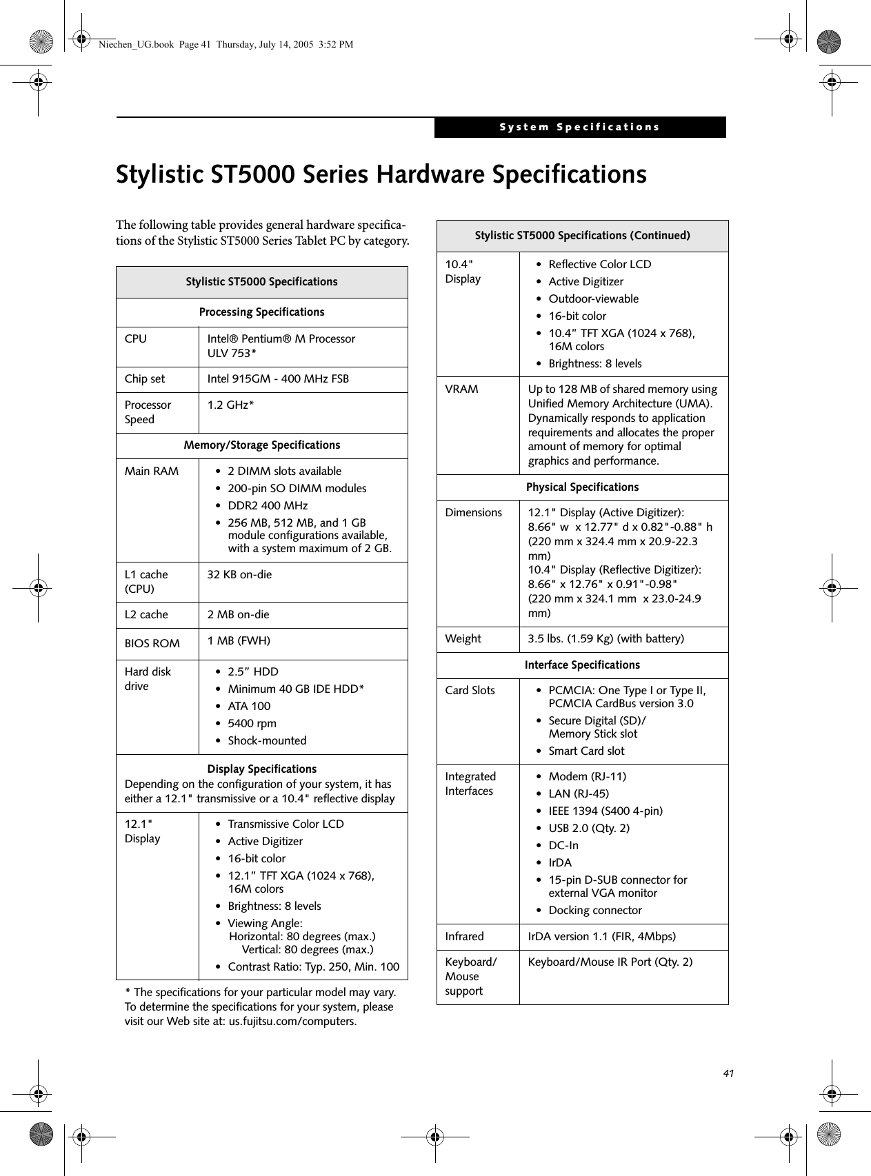
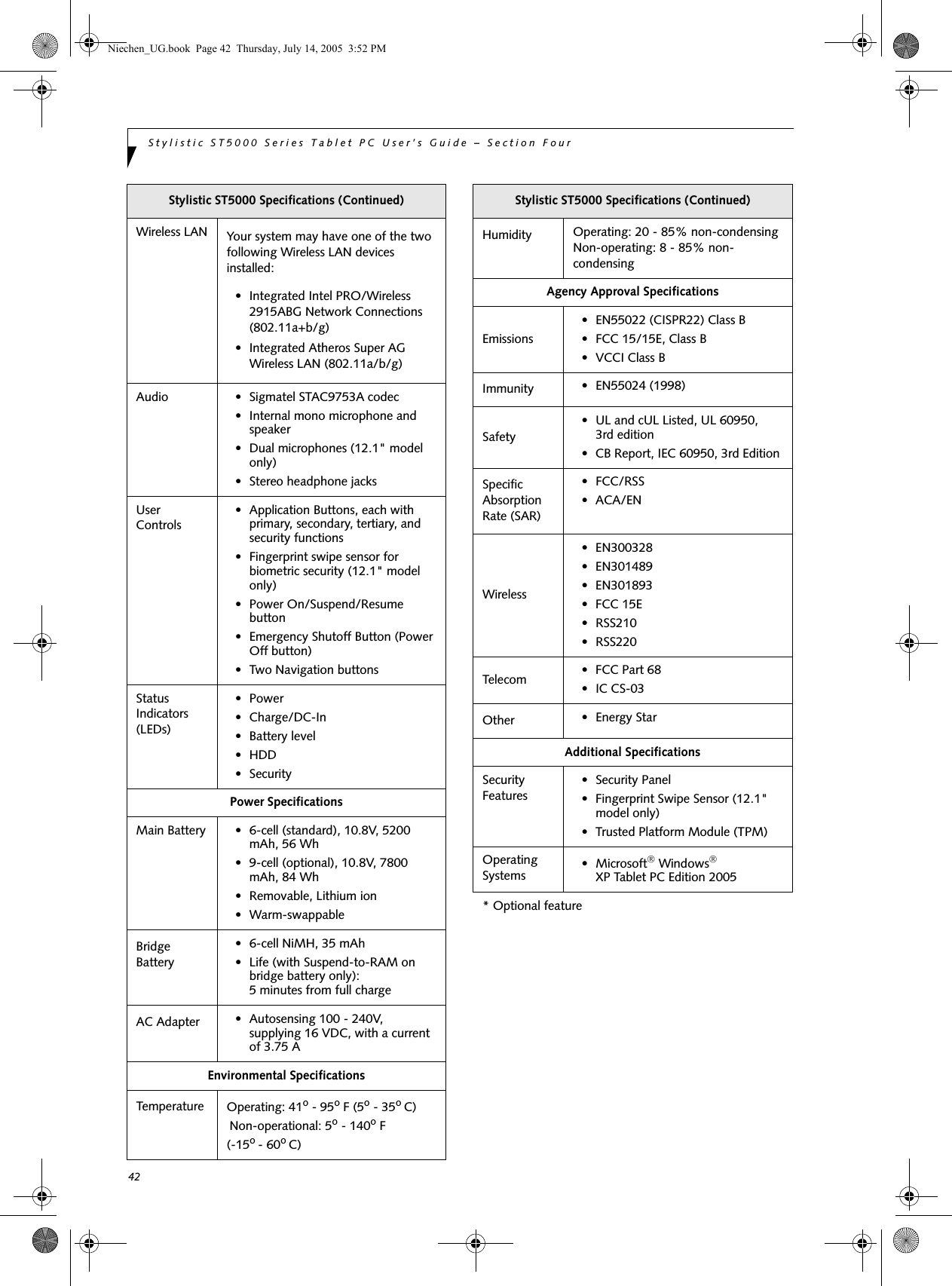
Fujitsu Client Computing WB0043 Stylistic ST Series with AR5BXB6 WLAN & Bluetooth User Manual App I2 part 2

Fujitsu Limited Stylistic ST Series with AR5BXB6 WLAN & Bluetooth App I2 part 2

App I2 user manual part 2
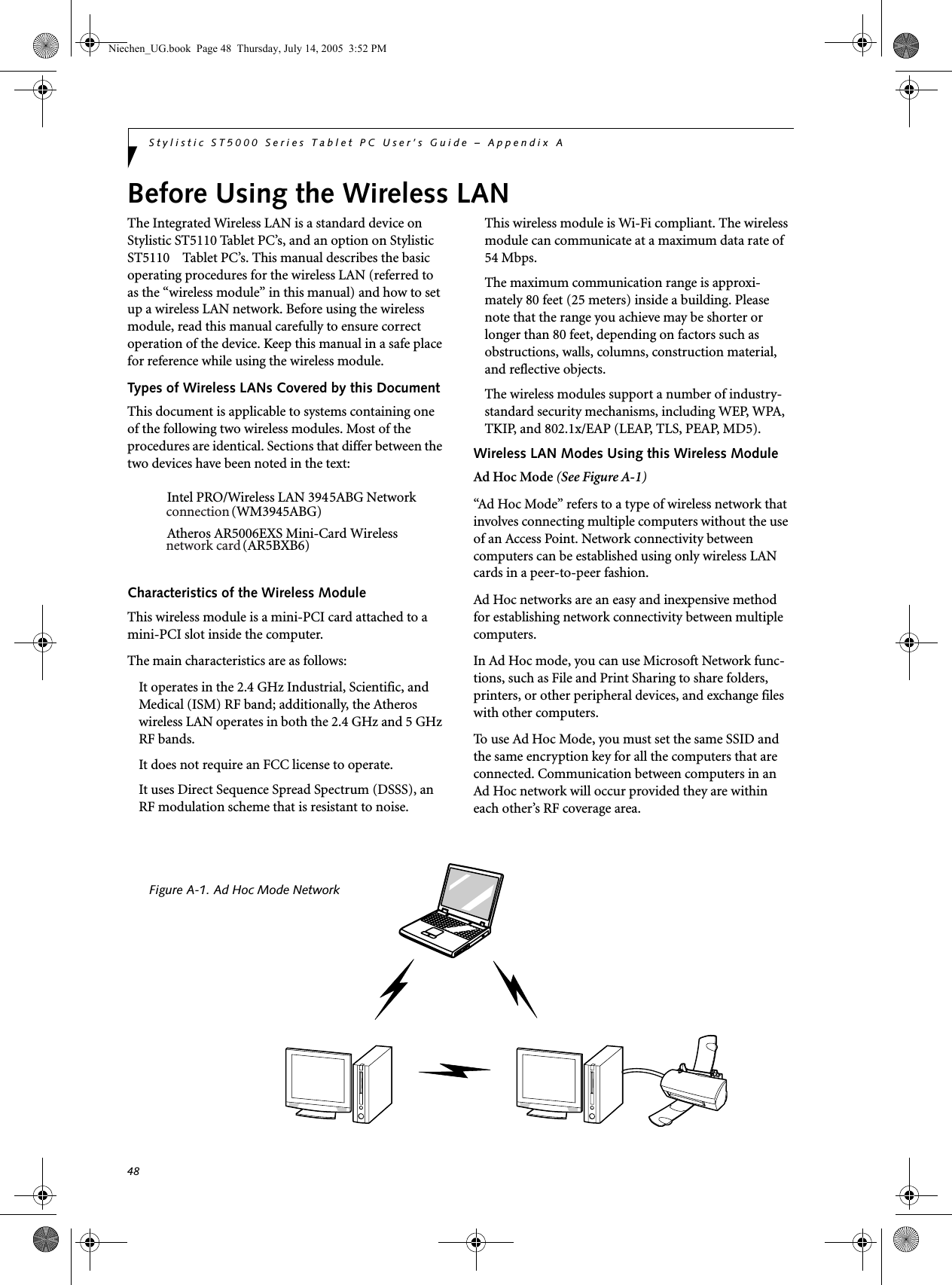
FCC ID: EJE-WB0043  (IC: 337J-WB0043)                                    Report No.  M060760_Cert_AR5BXB6_DTS_BT        EMC Technologies Pty Ltd – 57 Assembly Drive, Tullamarine VIC 3043 Australia www.emctech.com.au   EMC Technologies Report Number: M060760_Cert_AR5BXB6_DTS_BT    APPENDIX I2  FUJITSU NOTEBOOK USER MANUAL (part 2)
394SpecificationsNiechen_UG.book  Page 39  Thursday, July 14, 2005  3:52 PM
40Stylistic ST5000 Series Tablet PC User’s Guide – Section FourNiechen_UG.book  Page 40  Thursday, July 14, 2005  3:52 PM
41System SpecificationsStylistic ST5000 Series Hardware SpecificationsThe following table provides general hardware specifica-tions of the Stylistic ST5000 Series Tablet PC by category.Stylistic ST5000 SpecificationsProcessing SpecificationsCPU Intel® Pentium® M Processor ULV 753*Chip set Intel 915GM - 400 MHz FSBProcessor Speed1.2 GHz*Memory/Storage SpecificationsMain RAM • 2 DIMM slots available • 200-pin SO DIMM modules• DDR2 400 MHz• 256 MB, 512 MB, and 1 GB module configurations available, with a system maximum of 2 GB.L1 cache (CPU)32 KB on-die L2 cache 2 MB on-die BIOS ROM 1 MB (FWH)Hard disk drive• 2.5” HDD• Minimum 40 GB IDE HDD*•ATA 100• 5400 rpm• Shock-mountedDisplay SpecificationsDepending on the configuration of your system, it has either a 12.1" transmissive or a 10.4" reflective display12.1" Display• Transmissive Color LCD• Active Digitizer• 16-bit color• 12.1” TFT XGA (1024 x 768), 16M colors• Brightness: 8 levels• Viewing Angle:    Horizontal: 80 degrees (max.)     Vertical: 80 degrees (max.)• Contrast Ratio: Typ. 250, Min. 100* The specifications for your particular model may vary. To determine the specifications for your system, please visit our Web site at: us.fujitsu.com/computers.10.4" Display• Reflective Color LCD• Active Digitizer• Outdoor-viewable• 16-bit color• 10.4” TFT XGA (1024 x 768), 16M colors• Brightness: 8 levelsVRAM Up to 128 MB of shared memory using Unified Memory Architecture (UMA). Dynamically responds to application requirements and allocates the proper amount of memory for optimal graphics and performance. Physical SpecificationsDimensions 12.1" Display (Active Digitizer):8.66" w  x 12.77" d x 0.82"-0.88" h (220 mm x 324.4 mm x 20.9-22.3 mm)10.4" Display (Reflective Digitizer):8.66" x 12.76" x 0.91"-0.98"(220 mm x 324.1 mm  x 23.0-24.9 mm)Weight 3.5 lbs. (1.59 Kg) (with battery)Interface SpecificationsCard Slots • PCMCIA: One Type I or Type II, PCMCIA CardBus version 3.0• Secure Digital (SD)/Memory Stick slot•Smart Card slotIntegrated Interfaces• Modem (RJ-11)• LAN (RJ-45)• IEEE 1394 (S400 4-pin)• USB 2.0 (Qty. 2)•DC-In•IrDA• 15-pin D-SUB connector for external VGA monitor• Docking connectorInfrared IrDA version 1.1 (FIR, 4Mbps)Keyboard/Mouse supportKeyboard/Mouse IR Port (Qty. 2)Stylistic ST5000 Specifications (Continued)Niechen_UG.book  Page 41  Thursday, July 14, 2005  3:52 PM
42Stylistic ST5000 Series Tablet PC User’s Guide – Section FourWireless LAN Your system may have one of the two following Wireless LAN devices installed:• Integrated Intel PRO/Wireless 2915ABG Network Connections (802.11a+b/g)• Integrated Atheros Super AG Wireless LAN (802.11a/b/g)Audio • Sigmatel STAC9753A codec• Internal mono microphone and speaker• Dual microphones (12.1" model only)• Stereo headphone jacksUser Controls• Application Buttons, each with primary, secondary, tertiary, and security functions • Fingerprint swipe sensor for biometric security (12.1" model only)• Power On/Suspend/Resume button• Emergency Shutoff Button (Power Off button)• Two Navigation buttonsStatus Indicators (LEDs)• Power•Charge/DC-In• Battery level•HDD•SecurityPower SpecificationsMain Battery • 6-cell (standard), 10.8V, 5200 mAh, 56 Wh• 9-cell (optional), 10.8V, 7800 mAh, 84 Wh• Removable, Lithium ion• Warm-swappableBridge Battery• 6-cell NiMH, 35 mAh• Life (with Suspend-to-RAM on bridge battery only): 5 minutes from full chargeAC Adapter • Autosensing 100 - 240V, supplying 16 VDC, with a current of 3.75 AEnvironmental SpecificationsTemperature Operating: 41o - 95o F (5o - 35o C) Non-operational: 5o - 140o F (-15o - 60o C) Stylistic ST5000 Specifications (Continued)Humidity Operating: 20 - 85% non-condensingNon-operating: 8 - 85% non-condensingAgency Approval SpecificationsEmissions• EN55022 (CISPR22) Class B • FCC 15/15E, Class B• VCCI Class BImmunity • EN55024 (1998)Safety• UL and cUL Listed, UL 60950, 3rd edition• CB Report, IEC 60950, 3rd EditionSpecific Absorption Rate (SAR)• FCC/RSS• ACA/ENWireless• EN300328• EN301489• EN301893• FCC 15E• RSS210• RSS220Telecom • FCC Part 68• IC CS-03Other • Energy StarAdditional SpecificationsSecurity Features• Security Panel• Fingerprint Swipe Sensor (12.1" model only)• Trusted Platform Module (TPM)Operating Systems •Microsoft® Windows® XP Tablet PC Edition 2005* Optional featureStylistic ST5000 Specifications (Continued)Niechen_UG.book  Page 42  Thursday, July 14, 2005  3:52 PM
43System SpecificationsRegulatory InformationNOTICEChanges or modifications not expressly approved by Fujitsu could void this user’s authority to operate the equipment.FCC NOTICESNotice to Users of Radios and TelevisionThis equipment has been tested and found to comply with the limits for a Class B digital device, pursuant to part 15 of the FCC Rules.These limits are designed to provide reasonable protec-tion against harmful interference in a residential installa-tion. This equipment generates, uses, and can radiate radio frequency energy and, if not installed and used in accordance with the instructions, may cause harmful interference to radio communications. However, there is no guarantee that interference will not occur in a partic-ular installation. If this equipment does cause harmful interference to radio or television reception, which can be determined by turning the equipment off and on, the user is encouraged to try to correct the interference by one or more of the following measures:Reorient or relocate the receiving antenna.Increase the separation between the equipment and receiver.Connect the equipment into an outlet that is on a different circuit than the receiver.Consult the dealer or an experienced radio/TVtechnician for help.Shielded interconnect cables must be employed with this equipment to ensure compliance with the pertinent RF emission limits governing this device. Notice to Users of the US Telephone NetworkThis equipment    complies with Part 68 of the FCC rules, and the requirements adopted by ACTA. On the bottom of this equipment is a label that contains, among other information, the FCC registration number and ringer equivalence number (REN) for this equipment; or a product identifier in the format US:AAAEQ##TXXXX. If requested, this informa-tion or number must be provided to the telephone company.This equipment is designed to be connected to the tele-phone network or premises wiring using a standard jack type USOC RJ11C. A plug and jack used to connect this equipment to the premises wiring and telephone network must comply with the applicable FCC Part 68 rules and requirements adopted by the ACTA. A compliant tele-phone cord and modular plug is provided with this product. It is designed to be connected to a compatible modular jack that is also compliant.The ringer equivalent number (REN) of this equipment is 0.1B as shown on the label. The REN is used to deter-mine the number of devices that may be connected to a telephone line. Excessive RENs on a telephone may result in the devices not ringing in response to an incoming call. In most but not all areas, the sum of RENs should not exceed five (5.0). To be certain of the number of devices that may be connected to a line, as determined by the total RENs, contact the local telephone company. If this equipment causes harm to the telephone network, the telephone company will notify you in advance that temporary discontinuance of service may be required. But if advance notice isn’t practical, the telephone company will notify the customer as soon as possible. Also, you will be advised of your right to file a complaint with the FCC if you believe it is necessary.The telephone company may make changes in its facili-ties, equipment, operations or procedures that could effect the operation of the equipment. If this happens the telephone company will provide advance notice in order for you to make necessary modifications to maintain uninterrupted service. If trouble is experienced with this equipment, for repair or warranty information, please refer to the manual or contact Fujitsu Computer Systems Corporation, Customer Service. If the equipment is causing harm to the telephone network, the telephone company may request that you disconnect the equipment until the problem is resolved.The equipment cannot be used on public coin service provided by the telephone company. Connection to party line service is subject to state tariffs. (Contact the state public utility commission, public service commission or corporation commission for information). If your home has specially wired alarm equipment connected to the telephone line, ensure the installation of this computer does not disable your alarm equipment. If you have any questions about what will disable alarm equipment, consult your telephone company or a quali-fied installer.The Telephone Consumer Protection Act of 1991 makes it unlawful for any person to use a computer or other electronic device to send any message via a telephone fax machine unless such message clearly contains in a margin at the top or bottom of each transmitted page or on the first page of the transmission, the date an time it is sent and an identification of the business or other entity, or other individual sending the message and the telephone number of the sending machine or such business, other entity, or individual.Niechen_UG.book  Page 43  Thursday, July 14, 2005  3:52 PM
44Stylistic ST5000 Series Tablet PC User’s Guide – Section FourDOC (INDUSTRY CANADA) NOTICESNotice to Users of Radios and TelevisionThis Class B digital apparatus meets all requirements of Canadian Interference-Causing Equipment Regulations.CET appareil numérique de la class B respecte toutes les exigence du Réglement sur le matérial brouilleur du Canada.Notice to Users of the Canadian Telephone Network NOTICE: This equipment meets the applicable Industry Canada Terminal Equip-ment Technical Specifications. This is confirmed by the registration number. The abbreviation, IC, before the registration number signifies that registration was performed based on a Declaration of Conformity indi-cating that Industry Canada technical specifications were met. It does not imply that Industry Canada approved the equipment. Before connecting this equipment to a telephone line the user should ensure that it is permissible to connect this equipment to the local telecommunication facilities. The user should be aware that compliance with the certification standards does not prevent service degradation in some situations.Repairs to telecommunication equipment should be made by a Canadian authorized maintenance facility. Any repairs or alterations not expressly approved by Fujitsu or any equipment failures may give the telecom-munication company cause to request the user to disconnect the equipment from the telephone line.NOTICE: The Ringer Equivalence Number (REN) for this terminal equipment is 0 .1B. The REN assigned to each terminal equipment provides an indication of the maximum number of terminals allowed to be connected to a telephone interface. The termination on an interface may consist of any combination of devices subject only to the requirement that the sum of the Ringer Equiva-lence Numbers of all the devices does not exceed five.Avis Aux Utilisateurs Du Réseau Téléphonique CanadienAVIS: Le présent matériel est conforme aux spécifications techniques d’Industrie Canada applicables au matériel terminal. Cette confor-mité est confirmée par le numéro d’enregistrement. Le sigle IC, placé devant le numéro d’enregistrement, signifie que l’enregistrement s’est effectué conformé-ment à une déclaration de conformité et indique que les spécifications techniques d’Industrie Canada ont été respectées. Il n’implique pas qu’Industrie Canada a approuvé le matériel. Avant de connecter cet équipement à une ligne télépho-nique, l’utilisateur doit vérifier s’il est permis de connecter cet équipement aux installations de télécom-munications locales. L’utilisateur est averti que même la conformité aux normes de certification ne peut dans certains cas empêcher la dégradation du service.Les réparations de l’équipement de télécommunications doivent être eVectuées par un service de maintenance agréé au Canada. Toute réparation ou modification, qui n’est pas expressément approuvée par Fujitsu, ou toute défaillance de l’équipement peut entraîner la compagnie de télécommunications à exiger que l’utilisateur décon-necte l’équipement de la ligne téléphonique.AVIS: L’indice d’équivalence de la sonnerie (IES) du présent matéri el est de 0.1B. L’IES assigné à chaque dispositif terminal indique le nombre maximal de terminaux qui peuvent être raccordés à une interface téléphonique. La terminaison d’une interface peut consister en une combinaison quelconque de dispositifs, à la seule condition que la somme d’indices d’équiva-lence de la sonnerie de tous les dispositifs n’excède pas 5.For safety, users should ensure that the electrical ground of the power utility, the telephone lines and the metallic water pipes are connected together. Users should NOT attempt to make such connections themselves but should contact the appro-priate electric inspection authority or elec-trician. This may be particularly important in rural areas.Pour assurer la sécurité, les utilisateurs doivent vérifier que la prise de terre du ser-vice d’électricité, les lignes télphoniques et les conduites d’eau métalliques sont con-nectées ensemble. Les utilisateurs NE doivent PAS tenter d’établir ces connex-ions eux-mêmes, mais doivent contacter les services d’inspection d’installations électriques appropriés ou un électricien. Ceci peut être particulièrement important en régions rurales.Niechen_UG.book  Page 44  Thursday, July 14, 2005  3:52 PM
45Appendix AWireless LAN/Bluetooth* User’s Guide* Optional devicesNiechen_UG.book  Page 45  Thursday, July 14, 2005  3:52 PM
46Stylistic ST5000 Series Tablet PC User’s Guide – Appendix ANiechen_UG.book  Page 46  Thursday, July 14, 2005  3:52 PM
47Wireless LAN User’s Guide FCC REGULATORY INFORMATIONPlease note the following regulatory information related to the optional wireless LAN module.Regulatory Notes and StatementsWireless LAN, Health and Authorization for use Radio frequency electromagnetic energy is emitted from Wire-less LAN devices. The energy levels of these emissions, however, are far much less than the electromagnetic energy emissions from wireless devices such as mobile phones. Wireless LAN devices are safe for use by consumers because they operate within the guidelines found in radio frequency safety standards and recommendations. The use of Wireless LAN devices may be restricted in some situations or environments, such as:On board an airplane, orIn an explosive environment, orIn situations where the interference risk to other devices or services is perceived or identified as harmful.In cases in which the policy regarding use of Wireless LAN devices in specific environments is not clear (e.g., airports, hospitals, chemical/oil/gas industrial plants, private buildings), obtain authorization to use these devices prior to operating the equipment.Regulatory Information/DisclaimersInstallation and use of this Wireless LAN device must be in strict accordance with the instructions included in the user documentation provided with the product. Any changes or modifications made to this device that are not expressly approved by the manufacturer may void the user’s authority to operate the equipment. The manufacturer is not responsible for any radio or television interference caused by unauthorized modification of this device, or the substitution or attachment of connecting cables and equipment other than those specified by the manufacturer. It is the responsibility of the user to correct any interference caused by such unauthorized modifica-tion, substitution or attachment. The manufacturer and its authorized resellers or distributors will assume no liability for any damage or violation of government regulations arising from failure to comply with these guidelines. This device must not be co-located or operating in conjunction with any other antenna or transmitter.For   Wireless LAN:For operation within 5.15~5.25GHz frequency range, it is restricted to indoor environment, and the antenna of this device must be integral.Federal Communications Commission statementThis device complies with Part 15 of FCC Rules.Operation is subject to the following two conditions: (1) This device may not cause interference, and, (2) This device must accept any interference, including interference that may cause undesired operation of this device.FCC Interference StatementThis equipment has been tested and found to comply with the limits for a Class B digital device, pursuant to Part 15 of the FCC Rules. These limits are designed to provide reasonable protection against harmful interference in a residential installa-tion. This equipment generates, uses, and can radiate radio frequency energy. If not installed and used in accordance with the instructions, it may cause harmful interference to radio communications. However, there is no guarantee that interfer-ence will not occur in a particular installation.If this equipment does cause harmful interference to radio or television reception, which can be determined by turning the equipment off and on, the user is encouraged to try and correct the interference by one or more of the following measures:1. Reorient or relocate the receiving antenna.2. Increase the distance between the equipment and the receiver.3. Connect the equipment to an outlet on a circuit different from the one the receiver is connected to.4. Consult the dealer or an experienced radio/TV technician for help.FCC Radio Frequency Exposure statementThe available scientific evidence does not show that any health problems are associated with using low power wireless devices. There is no proof, however, that these low power wireless devices are absolutely safe. Low power wireless devices emit low levels of radio frequency energy (RF) in the microwave range while being used. Whereas high levels of RF can produce health effects (by heating tissue), exposure to low-level RF that does not produce heating effects causes no known adverse health effects. Many studies of low-level RF exposure have not found any biological effects. Some studies have suggested that some biological effects might occur, but such findings have not been confirmed by addi-tional research. The wireless LAN radio device has been tested and found to comply with FCC radiation exposure limits set forth for an uncontrolled equipment and meets the FCC radio frequency (RF) Exposure Guidelines in Supplement C to OET65.The maximum SAR values measured from the devices are:Intel PROSet Wireless LAN(WM3945ABG) : under evaluation Atheros Wireless LAN(AR5BXB6) :      1.57 W/kgIntel PROSet Wireless LAN(WM3945ABG)    + Bluetooth Simultaneous:  under evaluationAtheros Wireless LAN (AR5BXB6) +Bluetooth Simultaneous: 1.56 W/kgExport restrictionsThis product or software contains encryption code which may not be exported or transferred from the US or Canada without an approved US Department of Commerce export license. This device complies with Part 15 of FCC Rules., as well as ICES 003 B / NMB 003 B. Operation is subject to the following two conditions: (1) this device may not cause harmful interference, and (2) this device must accept any interference received, including interference that may cause undesirable operation. Modifications not expressly authorized by Fujitsu Computer Systems Corporation may invalidate the user's right to operate this equipment.Canadian NoticeNiechen_UG.book  Page 47  Thursday, July 14, 2005  3:52 PMThe device for the band 5150-5250 MHz is only for indoor usage toreduce the potential for harmful interference to co-channel mobilesatellite system.The maximum antenna gain of 6 dBi permitted (for devices in the5250-5350 MHz and 5470-5725 MHz bands) to comply with the e.i.r.p. limit.In addition, users are also cautioned to take note that high powerradars are allocated as primary users (meaning they have priority) of 5250-5350 MHz and 5650-5850 MHz and these radars could causeinterference and/or damage to LE-LAN devices.
48Stylistic ST5000 Series Tablet PC User’s Guide – Appendix ABefore Using the Wireless LAN The Integrated Wireless LAN is a standard device on Stylistic ST5110 Tablet PC’s, and an option on Stylistic ST5110    Tablet PC’s. This manual describes the basic operating procedures for the wireless LAN (referred to as the “wireless module” in this manual) and how to set up a wireless LAN network. Before using the wireless module, read this manual carefully to ensure correct operation of the device. Keep this manual in a safe place for reference while using the wireless module.Types of Wireless LANs Covered by this DocumentThis document is applicable to systems containing one of the following two wireless modules. Most of the procedures are identical. Sections that differ between the two devices have been noted in the text:Intel PRO/Wireless LAN 3945ABG NetworkAtheros AR5006EXS Mini-Card WirelessCharacteristics of the Wireless ModuleThis wireless module is a mini-PCI card attached to a mini-PCI slot inside the computer.The main characteristics are as follows:It operates in the 2.4 GHz Industrial, Scientific, and Medical (ISM) RF band; additionally, the Atheros wireless LAN operates in both the 2.4 GHz and 5 GHz RF bands.It does not require an FCC license to operate.It uses Direct Sequence Spread Spectrum (DSSS), an RF modulation scheme that is resistant to noise.This wireless module is Wi-Fi compliant. The wireless module can communicate at a maximum data rate of 54 Mbps.The maximum communication range is approxi-mately 80 feet (25 meters) inside a building. Please note that the range you achieve may be shorter or longer than 80 feet, depending on factors such as obstructions, walls, columns, construction material, and reflective objects.The wireless modules support a number of industry-standard security mechanisms, including WEP, WPA, TKIP, and 802.1x/EAP (LEAP, TLS, PEAP, MD5).Wireless LAN Modes Using this Wireless ModuleAd Hoc Mode (See Figure A-1)“Ad Hoc Mode” refers to a type of wireless network that involves connecting multiple computers without the use of an Access Point. Network connectivity between computers can be established using only wireless LAN cards in a peer-to-peer fashion.Ad Hoc networks are an easy and inexpensive method for establishing network connectivity between multiple computers.In Ad Hoc mode, you can use Microsoft Network func-tions, such as File and Print Sharing to share folders, printers, or other peripheral devices, and exchange files with other computers.To use Ad Hoc Mode, you must set the same SSID and the same encryption key for all the computers that are connected. Communication between computers in an Ad Hoc network will occur provided they are within each other’s RF coverage area. Figure A-1. Ad Hoc Mode NetworkNiechen_UG.book  Page 48  Thursday, July 14, 2005  3:52 PMconnection network card (WM3945ABG)(AR5BXB6)
49Wireless LAN User’s GuideAccess Point (Infrastructure) Mode (See Figure A-2)Infrastructure mode refers to a wireless network in which devices communicate with each other by first going through an Access Point (AP). In infrastructure mode, wireless devices can communicate with each other or can communicate with a wired network. Most corporate wireless LANs operate in infrastructure mode because they require access to the wired LAN in order to use services such as file servers or printers.How to Handle This Wireless ModuleThe Integrated Wireless LAN device is already installed in your mobile computer. Under normal circumstances, it should not be necessary for you to remove or re-install it. The wireless LAN has been configured to support the operating system with which your system shipped.FOR BETTER COMMUNICATIONSThis personal computer may not operate properly due to the operating environment. It is highly recommended that you observe the following precautions when using your wireless LAN module:■For optimum wireless communications, it recom-mended that operation of the wireless LAN module occur within 25 meters of the Access Point. Wireless range is dependent on a multitude of factors including number of obstructions, walls, type of construction material, reflective objects, etc.■If the computer is unable to communicate properly, change the channel to be used or the installation loca-tion. During the use of a microwave oven or other equipment generating strong high-frequency energy, in particular, the personal computer may be highly sus-ceptible to the energy and unable to communicate properly.■Broadcast stations or wireless communication equip-ment that operate in the 2.4GHz or 5GHz RF Fre-quency band may interfere with the operation of the wireless LAN module. Increasing of transmit power or relocating Access Points may be necessary to combat the effects of the interference.Figure A-2. Access Point (Infrastructure) Mode NetworkInternet ADSL modem,cable modem,or similarWired LANWireless LANAccess Point** An optional hub for a wiredLAN may be required depending upon the type of access point used.Niechen_UG.book  Page 49  Thursday, July 14, 2005  3:52 PM
50Stylistic ST5000 Series Tablet PC User’s Guide – Appendix ASTOPPING TRANSMISSION To use this product inside hospitals, clinics, or airplanes, or in other places where the use of electronic equipment is regulated, stop the transmission of radio waves from the wireless LAN beforehand.Deactivation using the wireless switchThe transmission of radio waves from the wireless LAN can be stopped by setting the wireless switch to the Off position. Note that the wireless LAN On/Off switch has no effect on non-wireless LAN models.(See Figure 3 for Wireless LAN switch location.)Figure A-3. Wireless LAN On/Off SwitchDeactivation using WindowsIntel PROSet Wireless LAN:1. Click [Start] --> [(All) Programs] --> [Intel Net-work Adapters] --> [Intel(R) PROSet]. The Intel(R) PROSet window will be displayed.2. Click the General tab.3. Select [Off] for the wireless communications Switch Radio: function, and then click the [OK] button. Wireless communications on/off switching will be deactivated and the transmission of radio waves from the wireless LAN will be stopped.Atheros Wireless LAN1. Click [Start] --> [Control Panel] --> [Atheros Cli-ent Utility]. The Atheros Wireless Configuration Utility window will be displayed.2. Click the Wireless Networks tab.3. Click the [Enable Radio] box to clear it, then click the [OK] button. Wireless communications on/off switching will be deactivated and the transmission of radio waves from the wireless LAN will be stopped.STARTING TRANSMISSION To communicate using the wireless LAN function, set the computer to a status from which it can transmit, as follows:Intel PROSet Wireless LAN:1. Set the wireless switch to the On position. 2. Click [Start] --> [(All) Programs] --> [Intel Net-work Adapters] --> [Intel(R) PROSet]. The Intel(R) PROSet window will be displayed.3. Click the [General] tab if it is not already selected.4. Select [ON] for the Switch radio: function, then click [OK]. Wireless communications on/off switching will be activated and the transmission of radio waves will be restarted.Atheros Wireless LAN:1. Click the Wireless Network Connection icon in the system tray at the lower right of your screen.2. Click [Enable Radio]. The radio will be turned on.Access Point Mode: Transmission is enabled.Ad Hoc Mode: Restart your computer to enable the radio.To restart transmission, select [On] for the wireless communications Switch Radio: function, and then click the [OK] button.Wireless LANOn/OffSwitchTo restart transmission, check the [Enable Radio] checkbox to select it., then click the [OK] button.Niechen_UG.book  Page 50  Thursday, July 14, 2005  3:52 PM
51Wireless LAN User’s GuideConnecting the WLANFLOW OF OPERATIONSThe wireless LAN connection procedure contained in this section is outlined below.1. Make sure the mobile computer is ready for the transmission of radio waves from the wireless LAN. For further details, see (See Starting Transmission on page 50 for more information.).2. Assign the parameters required for wireless LAN connection. (See Preparation for wireless LAN con-nection on page 51 for more information.).■Configure network name (SSID).■Configure wireless LAN security parameters as appropriate (e.g., WEP, TKIP, 802.1x/EAP).3. Perform setting operations relating to network con-nection. (See Connection to the network on page 53 for more information.)■Specify TCP/IP as the protocol, and confirm the name of the work group and other settings.■Enter the data required for file/printer sharing on the network. Perform this operation as required.■For access point (or “infrastructure”) connection, configure the wireless module with appropriate parameters required to associate to the access point network.■Verify that you are able to connect your computer to the network.PREPARATION FOR WIRELESS LAN CONNECTIONThis section explains the preparations required to use the wireless LAN when using the Windows XP Wireless Zero Configuration Tool. Configuration can also be accomplished using the wireless module (Intel or Atheros) configuration utility.Assigning parametersEnter the network name (SSID), the network key, and other data required for wireless LAN connection. If there is the administrator of the network, contact the network administrator for data settings.1. Make sure the Wireless LAN switch is switched on.2. Click the [Start] button first and then [Control Panel].3. If the Control Panel is in Category view, switch to Classic view by clicking “Switch to Classic View” under Control Panel the left frame. (If you are already in Classic view, “Switch to Category View” will be displayed instead.) 4. Double-click the Network Connections icon. A list of currently installed networks will be displayed.5. Right-click [Wireless Network Connection] in the list, and then click [Properties] in the menu dis-played. The [Wireless Network Connection Proper-ties] window will be displayed.6. Click the [Wireless Networks] tab.7. Click [Refresh], then choose the correct SSID from the [Available Networks] window. Click [Config-ure] and proceed to step 10. If the SSID of your access point does not appear in the list, click [Add]. The [Wireless Network Properties] window will be displayed.8. Select the Association tab if it is not already selected.9. Enter the information required for connection to the wireless LAN.a. Enter the network name (SSID). (i.e., Enter the name of the desired network in less than 33 ASCII characters).■To use access point (infrastructure) con-nection, refer to the access point manual for the access point-setting procedure.■You do not need to set the channel when using access point (infrastructure) mode. Channel selection is controlled by the access point. In ad hoc networks, channel selection defaults to channel 11; however, channel selection can be man-ually changed if desired. This can be accomplished only when using the client utility.If it is necessary to change the channel, change the setting of the access point. For the setting procedure, refer to the manual of the access point.Niechen_UG.book  Page 51  Thursday, July 14, 2005  3:52 PM
52Stylistic ST5000 Series Tablet PC User’s Guide – Appendix AFor ad hoc connection: Assign the same network name to all the personal computers to be connected.For access point (infrastructure) connection: Assign the appropriate SSID. The SSID must be identical to the SSID of the access point. Refer to the access point manual, or contact your network administrator.b. For ad hoc connection, check the following field. For access point (infrastructure) connection, clear the check mark for the following field:[This is a computer-to-computer (ad hoc) net-work; wireless access points are not used.]10. Choose the appropriate Network Authentication type. Options are Open, Shared, WPA, or WPA-PSK. Please contact your network administrator for the correct setting.11. Choose the Data Encryption type. Options are WEP, TKIP, or AES. The latter two encryption methods are available only when the Network Authentication scheme is WPA or WPA-PSK. WEP, TKIP, and AES are different methods used to encrypt communications data. Proceed to Step 11a if using static WEP keys, otherwise proceed to step 12.a. Clear the check mark from the [The key is provided for me automatically] check box.b.  Enter data in [Network Key]. Depending on the number of entered characters or digits, whether the key is an ASCII character code or a hexadec-imal code will be identified automatically.■Use five or thirteen characters to enter the key in the ASCII character code format. The characters that can be used as the “network key” are as fol-lows: 0 - 9, A - Z, _ (underscore), or, ■Use 10 or 26 characters to enter the key in the hexadecimal character code format. The charac-ters that can be used as the “network key” in this case are as follows: 0- 9, A - Z, a - fFor ad hoc connection: Assign the same network key to all the personal computers to be con-nected.For access point (infrastructure) connection: Assign the identical network key that is pro-grammed into the access point. For this setting, refer to the access point manual or contact your network administrator.c. Confirm the Network key by re-entering the same data in the [Confirm network key:] field.d. Make sure that the key index used is identical to the key index used by the Access Point(s).12. Click the [Authentication] tab and then verify the settings of [Enable network access control using IEEE 802.1x].For internal use at an organization such as a com-pany, when access by wireless LAN clients is to be limited using IEEE 802.1x authentication, check the [Enable network access control using IEEE 802.1x] check box.For home use, clear the check mark from [Enable network access control using IEEE 802.1x]. For the setting method relating to IEEE 802.1x authentication, refer to the manual of the access point which you are using.13. After completion of setting operations, click the [OK] button. Processing will return to the [Wire-less Network Connection Properties] window.14. Verify that the network name entered in step 7 above is added in [Preferred Networks], and then click the [OK] button.15. Close the [Wireless Network] window.It is strongly recommended that you enter the network key for encoding communications data. If the network key is not entered, since the network can be accessed from all personal computers containing the wireless LAN function, there is the danger of your data being stolen or damaged by other users.In [Preferred Networks], register only the desired connection settings.Niechen_UG.book  Page 52  Thursday, July 14, 2005  3:52 PM
53Wireless LAN User’s GuideCONNECTION TO THE NETWORKThis section explains connection to the network.If there is an administrator of the network, contact the network administrator for data settings.Setting the networkPerform the “Setting TCP/IP” and “Confirming the computer and work group names” operations required for network connection.Setting TCP/IP1. Click the [Start] button first and then [Control Panel].2. If the Control Panel is in Category view, switch to Classic view by clicking “Switch to Classic View” under Control Panel the left frame. (If you are already in Classic view, “Switch to Category View” will be displayed.) 3. Double-click [Network Connections]. A list of cur-rently installed networks will be displayed.4. Right-click [Wireless Network Connection] in the list, and then click [Properties] in the menu dis-played. The [Wireless Network Connection Proper-ties] window will be displayed.5. Click the [General] tab if it is not already selected.6. Click [Internet Protocol (TCP/IP] and then click [Properties]. The [Internet Protocol (TCP/IP) Properties] window will be displayed.7. Set the IP address as follows:■For ad hoc connection: Select [Use the following IP address:] and then enter data for [IP address] and [Subnet mask]. See page 62 for IP address setting.■For access point (infrastructure) connection: If your network uses DHCP, select [Obtain an IP address automatically] and [Obtain DNS server address automatically]. If your network uses static IP addresses, consult with your network adminis-trator for the correct IP address settings.8. Click the [OK] button. Processing will return to the [Wireless Network Connection Properties] window.9. Click the [OK] button.10. Close the [Network Connection] window. Following this operation, confirm the names of the computer and the workgroup as follows.Confirming the computer and work group names1. Click the [Start] button, then [Control Panel].2. If the Control Panel is in Category view, switch to Classic view by clicking “Switch to Classic View” under Control Panel the left frame. (If you are already in Classic view, “Switch to Category View” will be displayed.) 3. Double-click the [System] icon. The [System Prop-erties] window will be displayed.4. Click the [Computer Name] tab.5. Confirm the settings of [Full computer name:] and [Workgroup:].a. The setting of [Full computer name:] denotes the name for identifying the computer. Any name can be assigned for each personal computer. Enter the desired name in less than 15 ASCII character code format. Identifiability can be enhanced by entering the model number, the user name, and other factors.b. [Workgroup name] is the group name of the network. Enter the desired name in less than 15 ASCII character code format.For ad hoc connection: Assign the same network name to all personal computers existing on the network.For access point (infrastructure) connection: Assign the name of the work group to be accessed.6. Click the [OK] button. If a message is displayed that requests you to restart the personal computer, click [Yes] to restart the computer.Setting the sharing functionSet the sharing function to make file and/or printer sharing with other network-connected personal computers valid.To change the setting of the IP address, you need to be logged in from Windows as an administrator.To modify the computer name and/or the work group name, you need to be logged in from Windows as an administrator.To change the name, click [Change] and then proceed in accordance with the instruction messages displayed on the screen.Niechen_UG.book  Page 53  Thursday, July 14, 2005  3:52 PM
54Stylistic ST5000 Series Tablet PC User’s Guide – Appendix AThis operation is not required unless the sharing func-tion is to be used.The folder and printer for which the sharing function has been set will be usable from any personal computer present on the network.Setting the Microsoft network-sharing service1. Click the [Start] button first and then [Control Panel]. 2. If the Control Panel is in Category view, switch to Classic view by clicking “Switch to Classic View” under Control Panel the left frame. (If you are already in Classic view, “Switch to Category View” will be displayed.) 3. Double-click [Network Connections]. A list of cur-rently installed networks will be displayed.4. Right-click [Wireless Network Connection] in the list, and then click [Properties] in the menu dis-played. The [Wireless Network Connection Proper-ties] window will be displayed.5. If [File and Printer Sharing for Microsoft Net-works] is displayed, proceed to step 6. If [File and Printer Sharing for Microsoft Networks] is not dis-played, skip to step 7.6. Make sure that the [File and Printer Sharing for Microsoft Networks] check box is checked, and then click the [OK] button. Skip to “Setting file-sharing function”.7. Click [Install]. The [Select Network Component Type] window will be displayed.8. Click [Service], then click the [Add] button. The [Select Network Service] window will be displayed.9. Click [File and Printer Sharing for Microsoft Net-works] and then click the [OK] button. Processing will return to the [Wireless Network Connection Properties] window, and [File and Printer Sharing for Microsoft Networks] will be added to the list.10. Click the [Close] button.Setting the file-sharing functionThe procedure for setting the file-sharing function follows, with the “work” folder in drive C: as an example.1. Click the [Start] button first and then [My Com-puter]. 2. Double-click [Local disk (C:)].3. Right-click the “work” folder (or whichever folder you want to share), and then click [Sharing and Security...] in the menu displayed. The [Folder Name Properties] window will be displayed.4. Click [Sharing] if it isn’t already selected.5. Click the link stating “If you understand the secu-rity risks, but want to share files without running the wizard, click here”.6. Click “Just enable file sharing” and click [OK].7. Check the [Share this folder on the network] check box.8. Click the [OK] button. The folder will be set as a sharable folder, and the display of the icon for the “work.” folder will change.Setting the printer-sharing function1. Click the [Start] button first and then [Printers and FAX]. A list of connected printers will be displayed.2. Right-click the printer for which the sharing func-tion is to be set, and then click [Sharing] in the menu displayed. The property window correspond-ing to the selected printer will be displayed.3. Click the [Sharing] tab.4. Click [Share this printer].To share a file and/or the connected printer, you need to be logged in as an administrator.Setting the file-sharing function for the file which has been used to execute Network Setup Wizard is suggested on the screen. For the wireless LAN, however, since security is guaranteed by entry of the network name (SSID) and the network key, the steps to be taken to set the file-sharing function easily without using Network Setup Wizard are given below.To specify the corresponding folder as a read-only folder, select the [Read only] checkbox under the General tab.Setting the printer-sharing function when Network Setup Wizard has been executed is suggested on the screen. For the wireless LAN, however, since security is guaranteed by entry of the network name (SSID) and the network key, the steps to be taken to set the printer-sharing function without using Network Setup Wizard are laid down below.Niechen_UG.book  Page 54  Thursday, July 14, 2005  3:52 PM
55Wireless LAN User’s Guide5. Enter the sharing printer name in [Share name].6. Click the [OK] button. Confirming connectionAfter you have finished the network setup operations, access the folder whose sharing has been set for other personal computers. Also, confirm the status of the radio waves in case of trouble such as a network connection failure.Connecting your personal computer to another personal computer1. Click [Start] first and then [My Computer]. The [My Computer] window will be displayed in the left frame.2. Click [My Network Places] in the “Other Places” list. The window [My Network Places] will be dis-played.3. Click [View workgroup computers] under Network Tasks in the left frame.4.  Double-click the personal computer to which your personal computer is to be connected. The folder that was specified in “Setting the file-sharing func-tion” on page 54 will be displayed.5. Double-click the folder to be accessed.Confirming the status of the radioIntel PROSet Wireless LAN:1. Click [Start] -> [All Programs] -> [Intel Network Adapters] -> [Intel(R) PROSet]. The [Intel(R) PROSet] window will be displayed.2. Click the [General] tab and confirm radio status in the window displayed. The current connection sta-tus will be displayed.■Signal QualityThe quality of the signals is displayed on a graph.■Network name (SSID)The connected network name (SSID) is displayed.■Profile name“<No profile>” is displayed.■ModeIf access point (infrastructure) connection is in use, “Infrastructure (AP)” will be displayed. If ad hoc connection is in use, “Ad hoc (Peer-to-peer)” will be displayed.■SecurityDisplays the encryption type currently used by the radio.■SpeedDisplays the current data rate used by the radio to transmit and receive data.■Band (Frequency)The current operating frequency band is displayed. When communication is possible, “802.11b (2.4 GHz)” is displayed.■ChannelThe channel number currently being used for the communications is displayed.If connection cannot be made to the network or if you want to check for normal connection, see “Trouble-shooting” on page 58.Atheros Wireless LAN:1. Right-click the Atheros icon in the lower right cor-ner of the screen.2. Click [Open Client Utility]. The Atheros Wireless Configuration Utility window opens.3. Contained within the Current Status tab and Advanced Current Status, you will find the current operating status of the radio. (When the radio is turned off or the computer is not yet connected, some of the conditions will not be displayed.)■Profile NameThe current configuration profile is displayed.■Network Type - Configured Network Type[Access Point] or [AdHoc] will be displayed.■Current ModeIndicates the frequency and data rate currently used by the radio.■Current ChannelThe channel number currently used by the radio.■Link StatusDisplays the current connected state of the WLAN module.■Encryption TypeDisplays the encryption type currently used by the radio.In the case of access point (infrastructure) connection, enter the necessary data for the access point before confirming connection. Refer to the manual of the access point for the access point setup procedure.Niechen_UG.book  Page 55  Thursday, July 14, 2005  3:52 PM
56Stylistic ST5000 Series Tablet PC User’s Guide – Appendix A■IP AddressDisplays the current TCP/IP address assigned to the WLAN adapter.■CountryThe country with the country code for which the radio is configured.■Transmit Power LevelDisplays the current transmit power level of the radio.■Network Name (SSID)Displays the Network Name (SSID) currently used by the radio.■Power Save ModeDisplays the configured Power Save Mode currently used by the radio. [Off], [Normal], or [Maximum] will be displayed.■BSSIDDisplays the Basic Service Set Identifier. This is typically the MAC address of the Access Point or in the case of AdHoc networks, is a randomly generated MAC address.■FrequencyDisplays the center frequency currently being used by the radio.■Transmit RateDisplays the current data rate used by the radio to transmit data.■Receive RateDisplays the current data rate used by the radio to receive data.Niechen_UG.book  Page 56  Thursday, July 14, 2005  3:52 PM
57Wireless LAN User’s GuideOther settingsSETTING OF POWER-SAVING FUNCTIONYou can set the power-saving function of wireless LAN. Default setting is auto-setting. In case of using the power-saving function, manually control the communication performance.Intel PROSet Wireless LAN:1. Click [Start] -> [(All) Programs] -> [Intel Network Adapters] -> [Intel(R) PROSet]. The Intel(R) PROSet window will be displayed.2. Click the [Adapter] tab.3. Click the [Configure] button in [Power settings]. The [Power settings] window will be displayed.4. Select [Manual], and adjust the bar to set the power-saving function.Setting of transmission power during ad hoc connectionBy controlling the transmission power during ad hoc connection, you can broaden or narrow the communica-tion range. This setting is only effective during ad hoc connection. It will be ineffective during access point connection.Intel PROSet Wireless LAN:1. Click [Start] -> [(All) Programs] -> [Intel Network Adapters] -> [Intel(R) PROSet]. The Intel(R) PROSet window will be displayed.2. Click the [Adapter] tab.3. Click the [Configure] button in [Power settings]. The [Power settings] window will be displayed.4. Adjust the “Transmission Power (Ad Hoc)” bar to set the transmission power.Setting of channels during ad hoc connectionYou can set channels during ad hoc connection. Channel 11 is set by default. When connecting to an existing ad hoc network, no channel setting will be effective.This setting is only effective during ad hoc connection; it will be ineffective during access point connection.Intel PROSet Wireless LAN:1. Click [Start] -> [(All) Programs] -> [Intel Network Adapters] -> [Intel(R) PROSet]. The Intel(R) PROSet window will be displayed.2. Click the [Adapter] tab.3. Click the [Configure] button in [Ad hoc settings]. The [Ad hoc settings] window will be displayed.4. Change channels during ad hoc connection by selecting a new channel from the drop down list.5. Click [OK].Atheros Wireless LAN:1. Click on the My Computer icon. Select [View sys-tem information] from the left frame.2. Select the Hardware tab and click [Device Manager].3. Double-click “Atheros Wireless LAN Adapter” under [Network Adapters].4. In the Atheros Wireless LAN Adapter window, select the Advanced tab.5. Select IBSS Channel Number from the list, and change the value from the [Value:] dropdown list to the desired channel.6. Click [OK].When changing channels during ad hoc connection, change the channel settings of all connected computers with the same Network name (SSID) at the same time. After changing the channels, turn off all computers and -- after they are all turned off -- turn them back on.Niechen_UG.book  Page 57  Thursday, July 14, 2005  3:52 PM
58Stylistic ST5000 Series Tablet PC User’s Guide – Appendix ATroubleshootingCauses and countermeasures for troubles you may encounter while using your wireless LAN are described in the following table. Problem Possible Cause Possible SolutionUnavailable network connectionIncorrect network name (SSID) or network keyAd hoc connection: verify that the network names (SSID’s) and network keys (WEP) of all computers to be connected have been configured correctly. SSID’s and WEP key values must be identical on each machine.Access Point (Infrastructure) connection: set the network name (SSID) and network key to the same values as those of the access point. Set the Network Authentication value identically to that of the Access Point. Please consult your network administrator for this value, if necessary. For the method of setting network authentication, refer to the following pages:· “Assigning parameters” on page 51· Poor radio wave conditionAd hoc connection: Retry connection after shortening the distance to the destination computer or removing any obstacles for better sight.Access Point (Infrastructure) connection: Retry connection after short-ening the distance to the access point or removing any obstacles for better sight.To check the wave condition, refer to the following pages:· “Confirming the status of the radio waves” on page 55.·Radio wave transmission has stoppedCheck if the wireless switch is turned ON. Also verify “Disable Radio” is not checked in “Network setting” window. Refer to “Starting Transmis-sion” on page 50.The computer to be connected is turned offCheck if the computer to be connected is turned ON.Active channel duplication due to multiple wireless LAN networksIf there is any other wireless LAN network nearby, change channels to avoid active channel duplication. For the method of checking active channels, refer to the following pages:· “Confirming the status of the radio waves” on page 55· No right of access to the network to be connectedCheck if you have a right of access to the network to be connected with.Incorrectly-performed network settingCheck the protocol, work group name or shared setting.For the method of checking, refer to the following pages:· “Connection to the Network” on page 53.Unmatched [Network authentication (shared mode)] settings in Windows XPIf the setting of [Network authentication (shared mode)] is not matched with that of access point or computer to be connected with, no commu-nication can be established. Check the parameter setting. Refer to “Assigning parameters” on page 51.Niechen_UG.book  Page 58  Thursday, July 14, 2005  3:52 PM
59Wireless LAN User’s GuideUnavailable network connection(continued)It takes too long to retrieve the network and display the connected computers.Retrieve computers as follow: 1. Click [Start] button, then click [Search].2. Click [Computers or people].3. Click [Computers on the network].4. Input the name of computer to be connected with in [Computer name] and click [Search].5. Double-click the icon of connected computer.· Incorrect setting of IP addressCheck the network setting.“Setting the network” on page 53. In case of using TCP/IP protocol, you can check IP address as follows:1.  Click [Start] -> [All programs] -> [Accessories] -> [Command prompt].· 2. In [Command prompt] or [MS-DOS prompt] window, input [IPCONFIG] command as follows, then press [Enter] key.Example: In case of C drive being the hard disk: C:\ipconfig [Enter]Check that the IP address is correctly displayed:.IP Address................: 10.0.1.3Subnet Mask.............: 255.255.255.0Default Gateway.........: 10.0.1.1When IP address is displayed as [169.254.XXX.YYY] or [0.0.0.0], IP address is not correctly fetched from the access point. In that case, restart the computer itself. If the display is still unchanged, check the setting of TCP/IP.If [Cable Disconnected] or [Media Disconnected] is displayed without showing IP address, check the setting of network name (SSID) and network key. Also, set the network authentication according to the access point.Communication is disconnected soon after connection to the access point Access control may be disabledCheck the setting of “Enable network access control using IEEE 802.1X”.Refer to “Assigning parameters” on page 51.When restricting the access of wireless LAN clients using IEEE802.1X authentication, put a check mark on “Enable network access control using IEEE 802.1X”.When using at home, remove a check mark on “Enable network access control using IEEE802.1X”.For the method of setting related with IEEE802.1X authentication, refer to the access point manual.Authentication method may have been entered incorrectlyRe-enter your WEP key and verify that your authentication method (Open or Shared) is correct.Problem Possible Cause Possible SolutionNiechen_UG.book  Page 59  Thursday, July 14, 2005  3:52 PM
60Stylistic ST5000 Series Tablet PC User’s Guide – Appendix AWireless LAN GlossaryAccess pointA designation of wireless LAN network configurations. It indicates a form of communication using an Access Point. For details, refer to “access point connection” on page 48.Ad hocA designation for wireless LAN network configuration. It indicates a form of communication limited to those personal computers which have wireless LAN function. For details, refer to “Ad hoc connection” on page 48.ChannelThe frequency band of wireless LAN to be used in communications over wireless LAN or at the access point.DHCP (Dynamic Host Configuration Protocol)A protocol used for automatically fetching communica-tion parameters such as IP addresses. The side which assigns IP address is called DHCP server and the side that is assigned it is called DHCP client.DNS (Domain Name System)A function that controls the correspondence of IP addresses assigned to a computer with the name. Even for those computers whose IP addresses are unknown, if their names are known, it is possible to communicate with them.IEEE802.11aOne of the wireless LAN standards prescribed by the 802.11 committee in charge of establishing standards of LAN technology in IEEE (Institute of Electrical and Electronic Engineers). It allows communications at the maximum speed of 54 Mbps by using a 5GHz band which can freely be used without radio communication license. IEEE802.11bOne of the wireless LAN standards prescribed by the 802.11 committee in charge of establishing standards of LAN technology in IEEE (Institute of Electrical and Electronic Engineers). It allows communications at the maximum speed of 11Mbps by a band of 2.4 GHz (ISM band) which can freely be used without radio communi-cation license. IP addressAn address used by computers for communicating in TCP/IP environment. IP addresses have global and private addresses. A global address is a unique address in the world. A private address is a unique address within a closed network.LAN (Local Area Network)An environment connecting computers within a rela-tively small range, such as the same floor and building.MAC address (Media Access Control Address)A physical address inherent to a network card. For Ethernet, the top three bytes are controlled/assigned as a vendor code. The remaining three bytes comprise the code uniquely (to avoid duplication) controlled by each vendor. As a result, there is no Ethernet card with the same physical address in the world. In Ethernet, the frame transmission/reception is performed based on this address.MTU (Maximum Transmission Unit)The maximum size of data which can be transmitted at one time in networks including the Internet. In an envi-ronment whose maximum size of data is too large to correctly receive data, normal communications can be restored by setting the size of MTU to a smaller value.Network authenticationThe method of authentication performed by wireless LAN clients to connect with the access point. There are two types: open system authentication and shared key authentication. The type of authentication must be set to each client and also coincide with the setting of access point with which to communicate. Network authentica-tion is sometimes called authentication mode.Network keyData that is used for encrypting data in data communi-cation. The personal computer uses the same network key both for data encryption and decryption, therefore, it is necessary to set the same network key as the other side of communication.Network name (SSID: Service Set Identifier)The network name is a unique identifier attached to the WLAN packet header that acts as a password when the client attempts to connect to a WLAN. The SSID differ-entiates one WLAN from another so all WLAN devices attempting to connect to a specific WLAN must use the same SSID. SSID’s are transmitted in cleartext, thus supplying no security to the WLAN.Niechen_UG.book  Page 60  Thursday, July 14, 2005  3:52 PM
61Wireless LAN User’s GuideOpen system authenticationAn 802.11 wireless LAN authentication method. Open System does not exchange any key or other information, it is a simple request by the mobile station to be authenti-cated without verifying identity.PPPoE (Point to Point Protocol over Ethernet)A method of allowing the authentication protocol adopted in telephone line connection (PPP) to be used over an Ethernet.ProtocolA procedure or rule of delivering data among computers. Ordered data communication is allowed by making all conditions required for communication including the method of data transmission/reception and actions upon communication errors into procedures.Shared key authenticationAn 802.11 wireless LAN authentication method. When a client attempts to associate to an access point, the access point will send a challenge to the client. The client encrypts the challenge with the network key and sends it back to the access point. If the access point can decrypt the challenge, then authentication has succeeded.SSID (Service Set Identifier)See “Network name”Subnet maskTCP-IP network is controlled by being divided into multiple smaller networks (subnets). IP address consists of the subnet address and the address of each computer. Subnet mask defines how many bits of IP address comprise the subnet address. The same value shall be set among computers communicating with each other.TCP/IP (Transmission Control Protocol/Internet Protocol)A standard protocol of the Internet. Wi-Fi Short for “Wireless Fidelity”. A term meant to be used generically when referring to any type of 802.11 network, whether 802.11b, 802.11a, 802.11g, etc.Niechen_UG.book  Page 61  Thursday, July 14, 2005  3:52 PM
62Stylistic ST5000 Series Tablet PC User’s Guide – Appendix AIP address informationIf IP address is unknown, set IP address as follows:If you have an access point (DHCP server) on the network, set the IP address as follows:[Obtain an IP address automatically]If the IP address is already assigned to the computer in the network, ask the network administrator to check the IP address to be set for the computer.If no access point is found in the network:An IP address is expressed with four values in the range between 1 and 255.Set the each computer as follows: The value in paren-theses is a subnet mask.<Example>Computer A: 192.168.100.2 (255.255.255.0)Computer B: 192.168.100.3 (255.255.255.0)Computer C: 192.168.100.4 (255.255.255.0)::Computer X: 192.168.100.254 (255.255.255.0)IP addressing is much more complicated than can be briefly explained in this document. You are advised to consult with your network administrator for additional information.A DHCP server is a server that automatically assigns IP addresses to computers or other devices in the network. There is no DHCP server for the AdHoc network.Niechen_UG.book  Page 62  Thursday, July 14, 2005  3:52 PM
63Wireless LAN User’s GuideSpecifications* “Wi-Fi based” indicates that the interconnectivity test of the organization which guarantees the interconnectivity of wireless LAN (Wi-Fi Alliance) has been passed.** Encryption with network key (WEP) is performed using the above number of bits, however, users can set 40 bits/104 bits after subtracting the fixed length of 24 bits.*** The maximum number of computers that can be supported by an Access Point is highly variable, and can be affected by such factors as application bandwidth utilization, broadcast packet traffic, type of applications used, etc. The number of 10 provided by this document is meant only as a guideline and not a limitation of the technology.Item SpecificationType of network  Conforms to IEEE 802.11a/802.11b/g (Wi-Fi based)*Transfer rate (Automatic switching) 54 Mbps maximum data rate Active frequency 802.11b/g: 2400~2473 MHz 802.11a: 4900 ~ 5850 MHzNumber of channels 802.11a: 8 independent channels802.11b/g: 11 channels, 3 non-overlapping channels Security  • Encryption Types: WEP, TKIP, AES• WPA 1.0 compliant • Encryption Keylengths Supported: 64 bits, 128 bits, 152 bits (Atheros module using AES encryption only)• 802.1x/EAP• CCX 1.0 compliantMaximum recommended number of computers to be connected over wireless LAN (during ad hoc connection)10 units or less ***Niechen_UG.book  Page 63  Thursday, July 14, 2005  3:52 PM
64Stylistic ST5000 Series Tablet PC User’s Guide – Appendix AUsing the Bluetooth DeviceThe Integrated Bluetooth module (EYTF3CSFT)  is an optional device available for Fujitsu mobile computers.WHAT IS BLUETOOTH?Bluetooth technology is designed as a short-range wireless link between mobile devices, such as laptop computers, phones, printers, and cameras. Bluetooth technology is used to create Personal Area Networks (PANs) between devices in short-range of each other.WHERE TO FIND INFORMATION ABOUT BLUETOOTHThe Bluetooth module contains a robust Help user’s guide to assist you in learning about operation of the Bluetooth device.To access the Help file, click [Start] -> All Programs, and click on Toshiba. Select Bluetooth, then select User’s Guide.For additional information about Bluetooth Technology, visit the Bluetooth Web site at: www.bluetooth.com.FCC Radiation Exposure StatementThis equipment complies with FCC radiation exposure limits set forth for an uncontrolled environment.The transmitters in this device must not be co-located or operated in conjunction with any other antenna or transmitter.Canadian NoticeTo prevent radio interference to the licensed service, this device is intended to be operated indoors and away from windows to provide maximum shielding. Equipment (or its transmit antenna) that is installed outdoors is subject to licensing.WarrantyUsers are not authorized to modify this product. Any modifications invalidate the warranty.This equipment may not be modified, altered, or changed in any way without signed written permission from Fujitsu. Unauthorized modification will void the equipment authorization from the FCC and Industry Canada and the warranty.Niechen_UG.book  Page 64  Thursday, July 14, 2005  3:52 PM
65Appendix BSecurity Device* User’s Guide* Availability varies by modelNiechen_UG.book  Page 65  Thursday, July 14, 2005  3:52 PM
66Stylistic ST5000 Series Tablet PC User’s Guide – Appendix BNiechen_UG.book  Page 66  Thursday, July 14, 2005  3:52 PM
67Security Device User’s GuideFingerprint Sensor DeviceINTRODUCING THE FINGERPRINT SENSOR DEVICEYour system may have a fingerprint sensor device on the side of the display opposite the function buttons. The device is a standard feature on 12.1” models; it is not available on 10.4” models. (See Figure 1-2 on page 3 for location) Figure B-1  Fingerprint sensorWith a fingerprint sensor, you can avoid having to enter a username and password every time you want to:■Log onto Windows■Recover from suspend mode■Cancel a password-protected screen saver■Log into homepages that require a username and pass-wordAfter you have “enrolled” - or registered - your finger-print, you can simply swipe your fingertip over the sensor for the system to recognize you. The fingerprint sensor uses Softex OmniPass which provides password management capabilities to Microsoft Windows operating systems. OmniPass enables you to use a "master password" for all Windows, applications, and on-line passwords. OmniPass requires users to authenticate themselves using the fingerprint sensor before granting access to the Windows desktop. This device results in a secure authentication system for restricting access to your computer, applications, web sites, and other password-protected resources.OmniPass presents a convenient graphical user inter-face, through which you can securely manage pass-words, users, and multiple identities for each user.GETTING STARTEDThis section guides you through the preparation of your system for the OmniPass fingerprint recognition application. You will be led through the OmniPass installation process. You will also be led through the procedure of enrolling your first user into OmniPass. INSTALLING OMNIPASSIf OmniPass has already been installed on your system, skip this section and go directly to “User Enrollment” on page 68. You can determine whether OmniPass has already been installed by checking to see if the following are present:■The presence of the gold key-shaped OmniPass icon in the system tray at the bottom right of the screen.■The presence of the Softex program group in the Programs group of the Start menuSystem RequirementsThe OmniPass application requires space on your hard drive; it also requires specific Operating Systems (OS’s). The minimum requirements are as follows:■Windows XP Home Edition, Windows XP Profes-sional or Windows 2000 operating system■At least 35 MB available hard disk spaceInstalling the OmniPass ApplicationIf OmniPass is already installed on your system, go to “User Enrollment” on page 68. Otherwise continue with this section on software installation.To install OmniPass on your system you must:1.  Insert the installation media for the OmniPass application into the appropriate drive. If you are installing from CD-ROM or DVD-ROM, you must find and launch the OmniPass installation program (setup.exe) from the media.2.  Follow the directions provided in the OmniPass installation program. Specify a location to which you would like OmniPass installed. It is recom-mended that you NOT install OmniPass in the root directory (e.g. C:\). 3.  Once OmniPass has completed installation you will be prompted to restart you system. Once your system has rebooted you will be able to use OmniPass. If you choose not to restart immediately after installation, OmniPass will not be available for use until the next reboot.The installation program automatically places an icon (Softex OmniPass) in the Windows Control Panel as well as a golden key shaped icon in the taskbar. For installation, OmniPass requires that the user installing OmniPass have administrative privileges to the system. If your current user does not have administrative privileges, log out and then log in as an administrator before proceeding with OmniPass installation.Niechen_UG.book  Page 67  Thursday, July 14, 2005  3:52 PM
68Stylistic ST5000 Series Tablet PC User’s Guide – Appendix BVerifying Information about OmniPassAfter you have completed installing OmniPass and restarted your system, you may wish to check the version of OmniPass on your system.To check the version information of OmniPass:1.  From the Windows Desktop, double-click the key-shaped OmniPass icon in the taskbar (usually located in the lower right corner of the screen),or,Click the Start button, select Settings, and click Control Panel (if you are using Windows XP you will see the Control Panel directly in the Start menu; click it, then click Switch to Classic View). Double-click Softex OmniPass in the Control Panel, and the OmniPass Control Center will appear. If it does not appear, then the program is not properly installed,or,Click the Start button, select Programs, and from the submenu select the Softex program group, from that submenu click OmniPass Control Center.2. Select the About tab at the top of the OmniPass Control Panel. The About tab window appears with version information about OmniPass.Uninstalling OmniPassTo remove the OmniPass application from your system:1. Click Start on the Windows taskbar. Select Settings, and then Control Panel.2. Double-click Add/Remove Programs.3. Select OmniPass, and then click Change/Remove.4.  Follow the directions to uninstall the OmniPass application.5.  Once OmniPass has finished uninstalling, reboot your system when prompted.USER ENROLLMENTBefore you can use any OmniPass features you must first enroll a user into OmniPass.Master Password ConceptComputer resources are often protected with passwords. Whether you are logging into your computer, accessing your email, e-banking, paying bills online, or accessing network resources, you often have to supply credentials to gain access. This can result in dozens of sets of creden-tials that you have to remember.During OmniPass user enrollment a "master password” is created for the enrolled user. This master password “replaces” all other passwords for sites you register with OmniPass. Example: A user, John, installs OmniPass on his system (his home computer) and enrolls an OmniPass user with username “John_01” and password “freq14”. He then goes to his webmail site to log onto his account. He inputs his webmail credentials as usual (username “John_02” and password “tablet”), but instead of clicking [Submit], he directs OmniPass to Remember Password. Now whenever he returns to that site, OmniPass will prompt him to supply access credentials. John enters his OmniPass user credentials (“John_01” and “freq14”) in the OmniPass authentication prompt, and he is allowed into his webmail account. He can do this with as many web sites or password protected resources he likes, and he will gain access to all those sites with his OmniPass user credentials (“John_01” and “freq14”). This is assuming he is accessing those sites with the system onto which he enrolled his OmniPass user. OmniPass does not actually change the credentials of the password protected resource. If John were to go to an Internet cafe to access his webmail, he would need to enter his original webmail credentials (“John_02” and “tablet”) to gain access. If he attempts his OmniPass user credentials on a system other than where he enrolled that OmniPass user, he will not gain access.Basic EnrollmentThe Enrollment Wizard will guide you through the process of enrolling a user. Unless you specified other-wise, after OmniPass installation the Enrollment Wizard will launch on Windows login. If you do not see the Enrollment Wizard, you can bring it up by clicking Start on the Windows taskbar; select Programs; select Softex; click OmniPass Enrollment Wizard.1. Click Enroll to proceed to username and password verification. By default, the OmniPass Enrollment Wizard enters the credentials of the currently logged in Windows user.2. Enter the password you use to log in to Windows. This will become the “master password” for this For uninstallation, OmniPass requires that the user uninstalling OmniPass have administrative privileges to the system. If your current user does not have administrative privileges, log out and then log in as an administrator before proceeding with OmniPass uninstallation.The basic enrollment procedure assumes you have no hardware authentication devices or alternate storage locations that you wish to integrate with OmniPass. If you desire such functionality, consult the appropriate sections after reviewing this section.Niechen_UG.book  Page 68  Thursday, July 14, 2005  3:52 PM
69Security Device User’s GuideOmniPass user. In most cases, the Domain: value will be your Windows computer name. In a corporate environment, or when accessing corporate resources, the Domain: may not be your Windows computer name. Click [Next] to continue.3. In this step OmniPass captures your fingerprint. Refer to “Enrolling a Fingerprint” on page 69 for additional information.4. Next, choose how OmniPass notifies you of various events. We recommend you keep Taskbar Tips on Beginner mode taskbar tips and Audio Tips on at least Prompt with system beeps only until you get accustomed to how OmniPass operates. Click [Next] to proceed with user enrollment. You will then see a Congratulations screen indicating your completion of user enrollment.5. Click [Done] to exit the OmniPass Enrollment Wizard. You will be asked if you’d like to log in to OmniPass with your newly enrolled user; click [Yes].Enrolling a FingerprintEnrolling a fingerprint will increase the security of your system and streamline the authentication procedure. You enroll fingerprints in the OmniPass Control Center. With an OmniPass user logged in, double-click the system tray OmniPass icon. Select the User Settings tab and click Enrollment under the User Settings area. Click Enroll Authentication Device and authenticate at the authentication prompt to start device enrollment.1. During initial user enrollment, you will be prompted to select the finger you wish to enroll. Fingers that have already been enrolled will be marked by a green check. The finger you select to enroll at this time will be marked by a red arrow. OmniPass allows you to re-enroll a finger. If you choose a finger that has already been enrolled and continue enrollment, OmniPass will enroll the fingerprint, overwriting the old fingerprint. Select a finger to enroll and click [Next].2. It is now time for OmniPass to capture your selected fingerprint. It may take a several capture attempts before OmniPass acquires your fingerprint. Should OmniPass fail to acquire your fingerprint, or if the capture screen times out, click [Back] to restart the fingerprint enrollment process. Your system has a “swipe” fingerprint sensor. A swipe sensor is small and resembles a skinny elongated rect-angle. To capture a fingerprint, gently swipe or pull your fingertip over the sensor (starting at the second knuckle) in the direction of the arrow. Swiping too fast or too slow will result in a failed capture. The Choose Finger screen has a [Practice] button; click it to practice capturing your fingerprint. When you are comfortable with how your fingerprint is captured, proceed to enroll a finger.3.  Once OmniPass has successfully acquired the finger-print, the Verif y  Fin ger p r i nt screen will automati-cally appear. To verify your enrolled fingerprint, place your fingertip on the sensor and hold it there as if you were having a fingerprint captured. Successful fingerprint verification will show a green fingerprint in the capture window and the text Ve r i f i c a t i o n  Successful under the capture window.USING OMNIPASSYou are now ready to begin using OmniPass. Used regu-larly, OmniPass will streamline your authentication procedures.Password ReplacementYou will often use the password replacement function. When you go to a restricted access website (e.g., your bank, your web-based email, online auction or payment sites), you are always prompted to enter your login credentials. OmniPass can detect these prompts and you can teach OmniPass your login credentials. The next time you go to that website, you can authenticate with your fingerprint to gain access.OmniPass Authentication ToolbarAfter installing OmniPass and restarting, you will notice a dialog you have not seen before at Windows Logon. This is the OmniPass Authentication Toolbar, and it is displayed whenever the OmniPass authentication system is invoked. The OmniPass authentication system may be invoked frequently: during Windows Logon, during OmniPass Logon, when unlocking your workstation, when resuming from standby or hibernate, when unlocking a password-enabled screensaver, during pass-word replacement for remembered site or application logins, and more. When you see this toolbar, OmniPass is prompting you to authenticate.The Logon Authentication window indicates what OmniPass-restricted function you are attempting. The icons in the lower left (fingerprint and key) show what authentication methods are available to you. Selected authentication methods are highlighted while unselected methods are not. When you click the icon for an unse-lected authentication method, the authentication prompt associated with that method is displayed.When prompted to authenticate, you must supply the appropriate credentials: an enrolled finger for the finger-print capture window or your master password for the master password prompt (the key icon).Remembering a PasswordOmniPass can remember any application, GUI, or pass-word protected resource that has a password prompt.Niechen_UG.book  Page 69  Thursday, July 14, 2005  3:52 PM
70Stylistic ST5000 Series Tablet PC User’s Guide – Appendix BUsing the following procedure, you can store a set of credentials into OmniPass. These credentials will then be linked to your “master password” or fingerprint.Go to a site that requires a login (username and pass-word), but do not log in yet. At the site login prompt, enter your username and password in the prompted fields, but do not enter the site (do not hit [Enter], [Submit], [OK], or Login). Right-click the OmniPass system tray icon and select Remember Password from the submenu. The Windows arrow cursor will change to a golden key OmniPass cursor. Click this OmniPass cursor in the login prompt area, but do not click the [Login] or [Submit] button.Associating a Friendly NameAfter clicking the OmniPass key cursor near the login prompt, OmniPass will prompt you to enter a “friendly name” for this site. You should enter something that reminds you of the website, the company, or the service you are logging into. In its secure database, OmniPass associates this friendly name with this website.Additional Settings for Remembering a SiteWhen OmniPass prompts you to enter a “friendly name” you also have the opportunity to set how OmniPass authenticates you to this site. There are three effective settings for how OmniPass handles a remembered site.The default setting is Automatically click the “OK” or “Submit” button for this password protected site once the user is authenticated. With this setting, each time you navigate to this site OmniPass will prompt you for your master password or fingerprint authentication device. Once you have authenticated with OmniPass, you will automatically be logged into the site. Less secure is the option to Automatically enter this password protected site when it is activated. Do not prompt for authentication. Check the upper box to get this setting, and each time you navigate to this site OmniPass will log you into the site without prompting you to authenticate.If you uncheck both boxes in Settings for this Password Site, OmniPass will prompt you for your master pass-word or fingerprint authentication device. Once you have authenticated with OmniPass your credentials will be filled in to the site login prompt, but you will have to click the website [OK], [Submit], or [Login] button to gain access to the site. Click Finish to complete the remember password proce-dure. The site location, the credentials to access the site, and the OmniPass authentication settings for the site are now stored in the OmniPass secure database. The OmniPass authentication settings (Settings for this Pass-word Site) can always be changed in Vault Management.Logging in to a Remembered SiteWhether or not OmniPass prompts you to authenticate when you return to a remembered site is determined by Settings for this Password Site and can be changed in Vault Management. The following cases are applicable to using OmniPass to login to: Windows, remembered web sites, and all other password protected resources.With Master PasswordOnce you return to a site you have remembered with OmniPass, you may be presented with a master pass-word prompt. Enter your master password and you will be allowed into the site.Logging into Windows with a Fingerprint DeviceWhen logging into Windows with a fingerprint device, the fingerprint capture window will now appear next to the Windows Login screen. Place your enrolled fingertip on the sensor to authenticate. You will be simultaneously logged into Windows and OmniPass. The capture window will also appear if you have used Ctrl-Alt-Del to lock a system, and the fingerprint device can be used to log back in as stated above.In Windows XP, your login options must be set either for classic login, or for fast user switching and logon screen to be enabled to use your fingerprint to log on to Windows. To change this go to Control Panel, select User Accounts and then click Change the way users log on or off. If your Windows screensaver is password protected, the fingerprint capture window will now appear next to screensaver password dialog during resume. You can authenticate to your screensaver pass-word prompt with your enrolled finger.Password ManagementOmniPass provides an interface that lets you manage your passwords. To access this GUI, double-click the This setting is more convenient in that whenever you go to a site remembered with this setting, you will bypass any authentication procedure and gain instant access to the site. But should you leave your system unattended with your OmniPass user logged in, anyone using your system can browse to your password protected sites and gain automatic access.If a machine is locked and OmniPass detects a different user logging back in with a fingerprint, the first user will be logged out and the second user logged in.Niechen_UG.book  Page 70  Thursday, July 14, 2005  3:52 PM
71Security Device User’s GuideOmniPass key in the system tray. Click Vaul t Manage -ment; you will be prompted to authenticate. Once you gain access to Vault Management, click Manage Pass-words under Vault Settings. You will see the Manage Passwords interface, with a list of friendly names.You can view the credentials stored for any remembered website by highlighting the desired resource under Pass-word Protected Dialog and clicking Unmask Values. Should a password be reset, or an account expire, you can remove stored credentials from OmniPass. Highlight the desired resource under Password Protected Dialog and click Delete Page. You will be prompted to confirm the password deletion.The two check boxes in Manage Passwords govern whether OmniPass prompts you to authenticate or directly logs you into the remembered site.OmniPass will overwrite an old set of credentials for a website if you attempt to use Remember Password on an already remembered site. The exception to the above rule is the resetting of your Windows password. If your password is reset in Windows, then the next time you login to Windows, OmniPass will detect the password change and prompt you to “Update” or “Reconfirm” your password with OmniPass. Enter your new Windows password in the prompt(s) and click OK and your OmniPass "master password" will still be your Windows password.OmniPass User IdentitiesIdentities allow OmniPass users to have multiple accounts to the same site (e.g., bob@biblomail.com and boballen@biblomail.com). If OmniPass did not provide you identities, you would be limited to remembering one account per site.To create and manage identities, double-click the OmniPass key in the system tray. Click Vaul t Manage -ment; OmniPass will prompt you to authenticate. Once you gain access to Vault Management, click Manage Identities under Vault Settings. You can only manage the identities of the currently logged in OmniPass userTo add a new identity, click New Identity or double-click Click here to add a new identity. Name the new identity and click [OK], then click [Apply]. You can now switch to the new identity and start remembering passwords.To delete an identity, highlight the identity you want to delete and click [Delete Identity], then click [Apply].To set the default identity, highlight the identity you want as default and click [Set as Default]; click [Apply] to ensure the settings are saved. If you log in to OmniPass with a fingerprint device, you will automati-cally be logged in to the default identity for that OmniPass user. You can choose the identity with which you are logging in if you login using "master password".Choosing User Identity during LoginTo choose your identity during login, type your user-name in the User Name: field. Press [Tab] and see that the Domain: field self-populates. Click the Password: field to bring the cursor to it, and you will see the pull-down menu in the Identity: field. Select the identity you wish to login as and then click OK to login.Switch User IdentityTo switch identities at any time, right-click the OmniPass system tray icon and click Switch User Iden-tity from the submenu. The Switch Identity dialog will appear. Select the desired identity and then click OK.Identities and Password ManagementOn the Manage Passwords interface of the Va u l t  Management tab of the OmniPass Control Center, there is a pull-down selection box labeled, Identity. This field lets you choose which identity you are managing pass-words for. When you select an identity here, only those password protected dialogs that are associated with that identity are shown. You can perform all the functions explained in “Password Management” on page 70.CONFIGURING OMNIPASSThis section gives an overview of both the Export/Import function and the OmniPass Control Center. Exporting and Importing UsersUsing the OmniPass Control Center, you can export and import users in and out of OmniPass. The export process backs up all remembered sites, credentials, and any enrolled fingerprints for an OmniPass user. All OmniPass data for a user is backed up to a single encrypted database file. During the import process, the Windows login of the exported user is required. If the When you delete an identity, all of its associated remembered sites and password protected dialogs are lost.Niechen_UG.book  Page 71  Thursday, July 14, 2005  3:52 PM
72Stylistic ST5000 Series Tablet PC User’s Guide – Appendix Bproper credentials cannot be supplied, the user profile will not be imported. Exporting an OmniPass User ProfileTo export a user, open the OmniPass Control Center, and click Import/Export User under Manage Users. Click Exports an OmniPass user profile. OmniPass will prompt you to authenticate. Upon successfully authenti-cation, you must name the OmniPass user profile and decide where to save it. An .opi file is generated, and you should store a copy of it in a safe place.This .opi file contains all your user specific OmniPass data, and it is both encrypted and password protected. This user profile does NOT contain any of your encrypted data files.Importing an OmniPass User ProfileTo import an OmniPass user open the OmniPass Control Center, and click Import/Export User under Manage Users. Click Imports a new user into OmniPass and then select OmniPass Import/Export File (*.opi) and click Next. OmniPass will then prompt you to browse for the file you had previously exported (.opi file). When you select the .opi file for importation, OmniPass will prompt you for authentication. The credentials that will allow a user profile to be imported are the Windows login credentials of the exported user. They are the credentials that had to be submitted when the user profile was exported. You will need User Name, Password, and Domain. If you don’t remember the value for Domain, in a PC or SOHO environment Domain should be your computer name.OmniPass will notify you if the user was successfully imported.Things to Know Regarding Import/Export■Assume you export a local Windows User profile from OmniPass. You want to import that profile to another machine that has OmniPass. Before you can import the profile, a Windows user with the same login cre-dentials must be created on the machine importing the profile.Example: I have a Windows user with the username “Tom” and the password “Sunshine” on my system. I have enrolled Tom into OmniPass and remembered passwords. I want to take all my passwords to new sys-tem. I export Tom’s OmniPass user profile. I go to my new system and using the Control Panel I create a user with the username "Tom" and the password "Sun-shine". I can now successfully import the OmniPass user data to the new system.■If you export an OmniPass-only user, you can import that user to any computer running OmniPass, pro-vided that a user with that name is not already enrolled in OmniPass. ■If you attempt to import a user profile who has the same name as a user already enrolled in OmniPass, the OmniPass import function will fail.OMNIPASS CONTROL CENTERThis section will serve to explain functions within the OmniPass Control Center that weren’t explained earlier. You can access the OmniPass Control Center any of three ways:■Double-click the golden OmniPass key shaped icon in the Windows taskbar (typically in the lower-right cor-ner of the desktop)■Click the Start button; select the Programs group; select the Softex program group; and click the OmniPass Control Center selection.■Open the Windows Control Panel (accessible via Start button --> Settings --> Control Panel) and double-click the Softex OmniPass icon.User ManagementThe User Management tab has two major interfaces: Add/Remove User and Import/Export User. Import/Export User functionality is documented in “Exporting and Importing Users” on page 71. Add/Remove User functionality is straightforward. If you click Adds a new user to OmniPass you will start the OmniPass Enrollment Wizard. The Enrollment Wizard is documented in “User Enrollment” on page 68. ■You should periodically export your user profile and store it in a safe place. If anything happens to your system, you can import your OmniPass profile to a new system and have all your remem-bered settings and fingerprints instantly.■When you examine the importation, you are prompted for authentication. The credentials that will allow a user profile to be imported are the Windows login credentials of the exported user. They are the credentials that had to be submitted when the user profile was exported. You will need User Name, Password, and Domain.You cannot import a user into OmniPass if there already is a user with the same name enrolled in OmniPass. Niechen_UG.book  Page 72  Thursday, July 14, 2005  3:52 PM
73Security Device User’s GuideIf you click Removes a user from OmniPass, OmniPass will prompt you to authenticate. Authenticate with the credentials (or enrolled fingerprint) of the user you wish to remove. OmniPass will prompt you to confirm user removal. Click OK to complete user removal.User SettingsThe User Settings tab has four interfaces: Audio Settings, Taskba r Tip s, and Enrollment. User settings allow users to customize OmniPass to suit their individual prefer-ences. Under User Settings (Audio Settings and Ta s k b a r  Tips) you can set how OmniPass notifies the user of OmniPass events (e.g., successful login, access denied, etc.). The details of each setting under the Audio Settings and Tas kba r Tip s interfaces are self-explana-tory.The Enrollment interface allows you to enroll finger-prints. For the procedure to enroll and authentication device refer to Chapter 2.3. To enroll additional finger-prints, click Enroll Authentication Device, and authen-ticate with OmniPass. Select the fingerprint recognition device in the Select Authentication Device screen (it should already be marked by a green check if you have a finger enrolled) and click Next.System SettingsThe OmniPass Startup Options interface can be found in the System Settings tab. With these options you can specify how your OmniPass Logon is tied to your Windows Logon.The first option, Automatically log on to OmniPass as the current user, will do just as it says; during Windows login, you will be logged on to OmniPass using your Windows login credentials. If the user logging into Windows was never enrolled into OmniPass, upon login no one will be logged on to OmniPass. This setting is appropriate for an office setting or any setting where users must enter a username and password to log into a computer. This is the default setting.With the second option, Manually log on to OmniPass at startup, OmniPass will prompt you to login once you have logged on to Windows.With the third option, Do not log on to OmniPass at startup, OmniPass will not prompt for a user to be logged on.You can manually log on to OmniPass by right-clicking the OmniPass taskbar icon and clicking Log in User from the right-click menu.Removing a user will automatically destroy all OmniPass data associated with that user. All identities and credentials associated with the user will be lost. If you are sure about removing the user, we recommend you export the user profile.Niechen_UG.book  Page 73  Thursday, July 14, 2005  3:52 PM
74Stylistic ST5000 Series Tablet PC User’s Guide – Appendix BTROUBLESHOOTINGYou cannot use OmniPass to create Windows users. You must first create the Windows user, and you will need administrative privileges to do that. Once the Windows user is created, you can add that user to OmniPass using the same username and passwordCannot add Windows users to OmniPassIf you experience difficulties adding a Windows user to OmniPass, you may need to adjust your local secu-rity settings. You can do this by going to Start, Control Panel, Administrative Tools, and Local Security Settings. Expand Local Policies, expand Security Options, and double-click Network Access: Sharing and Security Model for Local Accounts. The correct setting should be Classic - Local Users Authen-ticate as Themselves.Cannot add a User with a Blank Password to OmniPassIf you experience difficulties adding a user with a blank password to OmniPass, you may need to adjust your local security settings. First attempt the proce-dure explained in the Cannot add Windows user to OmniPass section. If the difficulties persist, then try the following procedure.Click Start, Control Panel, Administrative Tools, and Local Security Settings. Expand Local Policies, expand Security Options, and double-click Accounts: Limit local account use of blank pass-words to console login only. This setting should be set to Disabled.Dialog appears after OmniPass authentication during Windows LogonAfter installing OmniPass on your system, you can choose to logon to Windows using OmniPass. You authenticate with OmniPass (via master password, or an enrolled security device) and OmniPass logs you into Windows. You may, during this OmniPass authentication, see a Login Error dialog box.This dialog box occurs when OmniPass was unable to log you into Windows with the credentials supplied (username and password). This could happen for any of the following reasons:■Your Windows password has changed■Your Windows account has been disabledIf you are having difficulties due to the first reason, you will need to update OmniPass with your changed Windows account password. Click Update Password and you will be prompted with a dialog to reconfirm your password.Enter the new password to your Windows user account and click OK. If the error persists, then it is unlikely the problem is due to your Windows user account password changing.Niechen_UG.book  Page 74  Thursday, July 14, 2005  3:52 PM
75Security Device User’s GuideTrusted Platform Module InstallationThis disc contains several utilities that allow you to enhance the security of your system using the optional Trusted Platform Module (TPM) contained in the sys-tem. TPM is a Trusted Computer Group (TCG)-compli-ant embedded security chip that allows computers to run applications more securely and to make transactions and communications more trustworthy. TPM is an important component of the Fujitsu Security Platform.ProcedureBe sure you have a built-in or external drive attached to your system that can read CDs. You will also need a means to write to removable media during the installa-tion.Enabling the Security Chip in BIOS1. Before installing the TPM software, you will need to enable the security chip in the system BIOS. To do so:• If your system is running, click [Start] -> Shut Down, and select Restart. Click [OK].• If the system is not running, power it up.2. When the Fujitsu logo appears, press the [F2] but-ton. The BIOS Setup Utility will appear.3. Open the Security menu, scroll down to Set Super-visor Password, and enter a password (if not already set).4. While in the Security menu, scroll down to Security Chip Setting, and click on it. The Security Chip Set-ting submenu will appear.5. Click on Security Chip to enable it.6. Click [F10] to save changes and exit.Installing the TPM Applications1. Insert the “Trusted Platform Module Drivers and Applications CD” in the drive.2. The setup program should start the installation automatically. If the installation does not start auto-matically, go to the setup.exe file on the disc and double-click on it.3. Follow the instructions that appear on your screen to load the drivers and applications for TPM.4. After loading the software, you will be prompted to reboot your system. Remove the CD from the drive, then reboot.5. After rebooting, the Security Platform Installation Wizard will open and lead you through the setup and customization of the TPM applications. Getting Help■For detailed help about installing the TPM applica-tions, go to the readme.txt file on the disc.■For in-depth help and information about the TPM applications, double-click on the Security Platform icon in the system tray, and click {Getting Started Guide].• The use of this disc requires that you have a device capable of reading CDs attached to your system. If you do not have a built-in CD or DVD player, you will need to attach an external player. • The use of this disc also requires a device capable of writing to removable media (such as a floppy disk drive, CD-RW drive, or PCMCIA memory card). This drive will be used to store the Emergency Recovery Token file and -- if desired -- the Emergency Recovery Archive file. For more information on available external devices, visit our Web site at: us.fujitsu.com/computers. When installing the software, be sure to create Emergency Recovery Archive and Emergency Recovery Token files when prompted by the Security Platform Initialization Wizard. These files will be necessary in the event of hardware failure. Failure to create these files could result in a loss of the Security Platform owner key, which is the physical root for secrets as well as the logical root for all Security Platform user-specific keys. The Initialization Wizard provides step-by-step instructions for creating the files. Niechen_UG.book  Page 75  Thursday, July 14, 2005  3:52 PM
76Stylistic ST5000 Series Tablet PC User’s Guide – Appendix BNiechen_UG.book  Page 76  Thursday, July 14, 2005  3:52 PM
77IndexIndexAadjusting the display brightness . . . . . . . . . . . . . . . . .  24air flow vents  . . . . . . . . . . . . . . . . . . . . . . . . . . . . . . . . .  5application buttons  . . . . . . . . . . . . . . . . . . . . . . . . . . . .  3application A  . . . . . . . . . . . . . . . . . . . . . . . . . . . . . .  10application B  . . . . . . . . . . . . . . . . . . . . . . . . . . . . . .  11Ctl-Alt-Del button   . . . . . . . . . . . . . . . . . . . . . . . . .  10display mode button . . . . . . . . . . . . . . . . . . . . . . . .  10EMail   . . . . . . . . . . . . . . . . . . . . . . . . . . . . . . . . . . . .  10enter button . . . . . . . . . . . . . . . . . . . . . . . . . . . . . . .  11escape button . . . . . . . . . . . . . . . . . . . . . . . . . . . . . .  10Fujitsu Menu Utility  . . . . . . . . . . . . . . . . . . . . . . . .  11function button . . . . . . . . . . . . . . . . . . . . . . . . . . . .  11Internet   . . . . . . . . . . . . . . . . . . . . . . . . . . . . . . . . . .  10orientation button   . . . . . . . . . . . . . . . . . . . . . . . . .  10security button   . . . . . . . . . . . . . . . . . . . . . . . . . . . .  10tertiary functions . . . . . . . . . . . . . . . . . . . . . . . .  13, 14Automatically Downloading Driver Updates  . . . . . .  37Bbattery gauge  . . . . . . . . . . . . . . . . . . . . . . . . . . . . . . . .  26battery gauge icon  . . . . . . . . . . . . . . . . . . . . . . . . . . . .  23battery icon   . . . . . . . . . . . . . . . . . . . . . . . . . . . . . . . . . .  9battery packcharging  . . . . . . . . . . . . . . . . . . . . . . . . . . . . . . . . . .  25critically low level  . . . . . . . . . . . . . . . . . . . . . . . . . .  23low-battery warning  . . . . . . . . . . . . . . . . . . . . . . . .  23no memory effect   . . . . . . . . . . . . . . . . . . . . . . . . . .  26overcharge protection . . . . . . . . . . . . . . . . . . . . . . .  26removing and installing  . . . . . . . . . . . . . . . . . . . . .  26will not begin charging  . . . . . . . . . . . . . . . . . . . . . .  26battery powerconserving  . . . . . . . . . . . . . . . . . . . . . . . . . . . . . . . .  26used in suspend-to-RAM mode . . . . . . . . . . . . . . .  23battery release latch . . . . . . . . . . . . . . . . . . . . . . . . .  4, 18BIOS  . . . . . . . . . . . . . . . . . . . . . . . . . . . . . . . . . . . . . . .  13application buttons, for  . . . . . . . . . . . . . . . . . .  13, 14BOOT Priority Change . . . . . . . . . . . . . . . . . . . . . . . .  36bridge battery . . . . . . . . . . . . . . . . . . . . . . . . . . . . . . . .  27built-in microphone  . . . . . . . . . . . . . . . . . . . . . . . . . . .  3Ccalibrating the pen . . . . . . . . . . . . . . . . . . . . . . . . . . . .  25care and maintenance  . . . . . . . . . . . . . . . . . . . . . . . . .  33charge/DC input icon  . . . . . . . . . . . . . . . . . . . . . . . . . .  8charging the battery pack  . . . . . . . . . . . . . . . . . . . . . . .25cleaning the display screen . . . . . . . . . . . . . . . . . . . . . .34configuring peripherals interface   . . . . . . . . . . . . . . . .35connectors and peripheral interfaces   . . . . . . . . . . . . .17conserving battery power . . . . . . . . . . . . . . . . . . . . . . .26conventions used in the guide  . . . . . . . . . . . . . . . . . . . .vcritically low battery level . . . . . . . . . . . . . . . . . . . . . . .23cursornot tracking pen  . . . . . . . . . . . . . . . . . . . . . . . . . . . .35DDC input connector  . . . . . . . . . . . . . . . . . . . . . . . . .6, 17DIMM card, removing  . . . . . . . . . . . . . . . . . . . . . . . . .29displayscreen is blank . . . . . . . . . . . . . . . . . . . . . . . . . . . . . .35screen, cleaning . . . . . . . . . . . . . . . . . . . . . . . . . . . . .34Drivers and Application Restore CD   . . . . . . . . . . . . .35Eexternal monitor connector . . . . . . . . . . . . . . . . . . . . . .6FFDU  . . . . . . . . . . . . . . . . . . . . . . . . . . . . . . . . . . . . . . . .37fingerprint sensor device  . . . . . . . . . . . . . . . . . . . . .3, 67enrolling a fingerprint  . . . . . . . . . . . . . . . . . . . . . . .69importing an OmniPass user profile . . . . . . . . . . . .72installing OmniPass  . . . . . . . . . . . . . . . . . . . . . . . . .67introducing the fingerprint sensor device   . . . . . . .67using OmniPass   . . . . . . . . . . . . . . . . . . . . . . . . . . . .69verifying information about OmniPass  . . . . . . . . .68Fujitsu contact information . . . . . . . . . . . . . . . . . . . . . .vFujitsu Driver Update utility  . . . . . . . . . . . . . . . . . . . .37Fujitsu online   . . . . . . . . . . . . . . . . . . . . . . . . . . . . . . . . .vHhard disk drive access icon . . . . . . . . . . . . . . . . . . . . . . .9headphone  . . . . . . . . . . . . . . . . . . . . . . . . . . . . . . . . . . . .6headphone jack  . . . . . . . . . . . . . . . . . . . . . . . . . . . . . . .17Hibernate (Save-to-Disk) mode  . . . . . . . . . .  21, 23, 24Iidle state  . . . . . . . . . . . . . . . . . . . . . . . . . . . . . . . . . . . . .21IEEE 1394 jack . . . . . . . . . . . . . . . . . . . . . . . . . . . . . .6, 18Niechen_UG.book  Page 77  Thursday, July 14, 2005  3:52 PM
78Stylistic ST5000 Series Tablet PCinfrared data transfer not working   . . . . . . . . . . . . . .  35infrared keyboard port  . . . . . . . . . . . . . . . . . . . . . . .  3, 7infrared keyboard/mouse port . . . . . . . . . . . . . . . . . .  18Installing a Memory Stick . . . . . . . . . . . . . . . . . . . . . .  27interfacesconnectors and peripherals  . . . . . . . . . . . . . . . . . .  17IrDA port  . . . . . . . . . . . . . . . . . . . . . . . . . . . . . . . . . . . .  5IrDA/FIR port  . . . . . . . . . . . . . . . . . . . . . . . . . . . . . . .  17LLAN jack . . . . . . . . . . . . . . . . . . . . . . . . . . . . . . . . . . . . .  6Local Area Network (LAN)   . . . . . . . . . . . . . . . . . . . .  18Lock   . . . . . . . . . . . . . . . . . . . . . . . . . . . . . . . . . . . . .  6, 18low-battery warning  . . . . . . . . . . . . . . . . . . . . . . . . . .  23Mmemory cover  . . . . . . . . . . . . . . . . . . . . . . . . . . . . . . . .  4memory module  . . . . . . . . . . . . . . . . . . . . . . . . . . . . .  29Memory Stick   . . . . . . . . . . . . . . . . . . . . . . . . . . . . . . . .  5installing . . . . . . . . . . . . . . . . . . . . . . . . . . . . . . . . . .  27microphone  . . . . . . . . . . . . . . . . . . . . . . . . . . . . . . . . . .  6microphone jack  . . . . . . . . . . . . . . . . . . . . . . . . . . . . .  17modem  . . . . . . . . . . . . . . . . . . . . . . . . . . . . . . . . . . . . .  17connection  . . . . . . . . . . . . . . . . . . . . . . . . . . . . . . . .  27jack  . . . . . . . . . . . . . . . . . . . . . . . . . . . . . . . . . . . . . . .  6Nnavigation buttons   . . . . . . . . . . . . . . . . . . . . . . . . .  3, 12OOff state   . . . . . . . . . . . . . . . . . . . . . . . . . . . . . . . . .  21, 22OmniPassControl Center   . . . . . . . . . . . . . . . . . . . . . . . . . . . .  72importing an OmniPass user profile . . . . . . . . . . .  72installing . . . . . . . . . . . . . . . . . . . . . . . . . . . . . . . . . .  67using . . . . . . . . . . . . . . . . . . . . . . . . . . . . . . . . . . . . .  69verifying information  . . . . . . . . . . . . . . . . . . . . . . .  68optional accessories . . . . . . . . . . . . . . . . . . . . . . . . . . . .  2additional accessories  . . . . . . . . . . . . . . . . . . . . . . . .  2carrying cases . . . . . . . . . . . . . . . . . . . . . . . . . . . . . . .  2docking options . . . . . . . . . . . . . . . . . . . . . . . . . . . . .  2input devices  . . . . . . . . . . . . . . . . . . . . . . . . . . . . . . .  2media options  . . . . . . . . . . . . . . . . . . . . . . . . . . . . . .  2memory  . . . . . . . . . . . . . . . . . . . . . . . . . . . . . . . . . . .  2power options  . . . . . . . . . . . . . . . . . . . . . . . . . . . . . .  2overheating, avoiding  . . . . . . . . . . . . . . . . . . . . . . . . . .34Ppage up/page down . . . . . . . . . . . . . . . . . . . . . . . . . . . .18PC Card eject button   . . . . . . . . . . . . . . . . . . . . . . . . . . .5PC card slot  . . . . . . . . . . . . . . . . . . . . . . . . . . . .  5, 17, 28PC Cardsremoving  . . . . . . . . . . . . . . . . . . . . . . . . . . . . . . . . . .28pen  . . . . . . . . . . . . . . . . . . . . . . . . . . . . . . . . . . . . . . . .5, 7installing a pen tether . . . . . . . . . . . . . . . . . . . . . . . .25not responding  . . . . . . . . . . . . . . . . . . . . . . . . . . . . .35replacing the tip   . . . . . . . . . . . . . . . . . . . . . . . . . . . .25using . . . . . . . . . . . . . . . . . . . . . . . . . . . . . . . . . . . . . .24pen tether . . . . . . . . . . . . . . . . . . . . . . . . . . . . . . . . . . . .25pen tether point . . . . . . . . . . . . . . . . . . . . . . . . . . . . . . . .5peripheral connectors . . . . . . . . . . . . . . . . . . . . . . . . . .17power icon  . . . . . . . . . . . . . . . . . . . . . . . . . . . . . . . . .8, 22blinking  . . . . . . . . . . . . . . . . . . . . . . . . . . . . . . . .22, 23not displayed . . . . . . . . . . . . . . . . . . . . . . . . . . . . . . .22power on/suspend/resumebutton   . . . . . . . . . . . . . . . . . . . . . . . . . . . . . . . . . . . . .3power usage  . . . . . . . . . . . . . . . . . . . . . . . . . . . . . . . . . .21powering up the pen tablet   . . . . . . . . . . . . . . . . . . . . .22preparation for wireless LAN connection . . . . . . . . . .51problems, solving  . . . . . . . . . . . . . . . . . . . . . . . . . . . . .34protecting the display screen  . . . . . . . . . . . . . . . . . . . .33Rremovable battery pack   . . . . . . . . . . . . . . . . . . . . . . . . .4removing a DIMM card  . . . . . . . . . . . . . . . . . . . . . . . .29removing a Memory Stick  . . . . . . . . . . . . . . . . . . . . . .28restoring the factory image   . . . . . . . . . . . . . . . . . . . . .36restoring your pre-installed software  . . . . . . . . . . . . .35resuming system operation  . . . . . . . . . . . . . . . . . .24, 34RJ-45   . . . . . . . . . . . . . . . . . . . . . . . . . . . . . . . . . . . . . . .18SSave-to-Disk mode  . . . . . . . . . . . . . . . . . . . . . . . . . . . .21SD Cardremoving  . . . . . . . . . . . . . . . . . . . . . . . . . . . . . . . . . .28SD Card slot   . . . . . . . . . . . . . . . . . . . . . . . . . . . . . . . . .17SD Card/Memory Stick Slot   . . . . . . . . . . . . . . . . . . . . .5Secure Digital Cardremoving  . . . . . . . . . . . . . . . . . . . . . . . . . . . . . . . . . .28Niechen_UG.book  Page 78  Thursday, July 14, 2005  3:52 PM
79IndexSecurity Application Paneloperating  . . . . . . . . . . . . . . . . . . . . . . . . . . . . . . . . .  15passwords . . . . . . . . . . . . . . . . . . . . . . . . . . . . . . . . .  14uninstalling  . . . . . . . . . . . . . . . . . . . . . . . . . . . . . . .  15Setting up Security Panel  . . . . . . . . . . . . . . . . . . . . . .  14shutting down the system . . . . . . . . . . . . . . . . . . . . . .  22Smart Card slot  . . . . . . . . . . . . . . . . . . . . . . . . . . . . . . .  5solving problems  . . . . . . . . . . . . . . . . . . . . . . . . . . . . .  34speaker  . . . . . . . . . . . . . . . . . . . . . . . . . . . . . . . . . . . . . .  3speaker/headphone volume too low  . . . . . . . . . . . . .  35status display  . . . . . . . . . . . . . . . . . . . . . . . . . . . . . . . . .  8battery icon  . . . . . . . . . . . . . . . . . . . . . . . . . . . . . . . .  9charge/DC input icon  . . . . . . . . . . . . . . . . . . . . . . . .  8hard disk drive access icon  . . . . . . . . . . . . . . . . . . . .  9power icon, blinking . . . . . . . . . . . . . . . . . . . . . . . .  22power icon, system states indicated by  . . . . . . .  8, 22storing the system unit  . . . . . . . . . . . . . . . . . . . . . . . .  34Stylistic ST5000care and maintenance . . . . . . . . . . . . . . . . . . . . . . .  33features . . . . . . . . . . . . . . . . . . . . . . . . . . . .  3, 4, 5, 6, 7items included with . . . . . . . . . . . . . . . . . . . . . . . . . .  1storing   . . . . . . . . . . . . . . . . . . . . . . . . . . . . . . . . . . .  34Stylistic ST5000 specificationsadditional . . . . . . . . . . . . . . . . . . . . . . . . . . . . . . . . .  42agency approval . . . . . . . . . . . . . . . . . . . . . . . . . . . .  42display   . . . . . . . . . . . . . . . . . . . . . . . . . . . . . . . . . . .  41environmental  . . . . . . . . . . . . . . . . . . . . . . . . . . . . .  42interface  . . . . . . . . . . . . . . . . . . . . . . . . . . . . . . . . . .  41physical   . . . . . . . . . . . . . . . . . . . . . . . . . . . . . . . . . .  41power  . . . . . . . . . . . . . . . . . . . . . . . . . . . . . . . . . . . .  42processing   . . . . . . . . . . . . . . . . . . . . . . . . . . . . . . . .  41suspend mode, determining . . . . . . . . . . . . . . . . . . . .  23Suspend/Resumedisabled   . . . . . . . . . . . . . . . . . . . . . . . . . . . . . . . . . .  23Suspend/Resume button . . . . . . . . . . . . . . . . . . . . . . .  18suspending system operation  . . . . . . . . . . . . . . . . . . .  22Suspend-to-RAM   . . . . . . . . . . . . . . . . . . . . . . . . . . . .  21mode   . . . . . . . . . . . . . . . . . . . . . . . . . . . . . . . . .  23, 24system interface connector . . . . . . . . . . . . . . . . . . . . . .  4system states . . . . . . . . . . . . . . . . . . . . . . . . . . . . . .  21, 22Hibernate (Save-to-Disk) . . . . . . . . . . . . . . . . . . . .  21Idle state . . . . . . . . . . . . . . . . . . . . . . . . . . . . . . . . . .  21Off state  . . . . . . . . . . . . . . . . . . . . . . . . . . . . . . . . . .  21On state   . . . . . . . . . . . . . . . . . . . . . . . . . . . . . . . . . .  21Suspend-to-RAM  . . . . . . . . . . . . . . . . . . . . . . . . . .  21system status LEDs   . . . . . . . . . . . . . . . . . . . . . . . . . . . .  3system will not resume operation  . . . . . . . . . . . . . . .  34TTablet Dock latch point  . . . . . . . . . . . . . . . . . . . . . . . . .4Tablet Dock port . . . . . . . . . . . . . . . . . . . . . . . . . . . . . .17tertiary functions of application buttons  . . . . . . .13, 14thermal suede   . . . . . . . . . . . . . . . . . . . . . . . . . . . . . . . . .4troubleshooting . . . . . . . . . . . . . . . . . . . . . . . . . . . . . . .34Trusted Platform Moduleenabling the security chip in BIOS  . . . . . . . . . . . . .75getting help  . . . . . . . . . . . . . . . . . . . . . . . . . . . . . . . .75installation . . . . . . . . . . . . . . . . . . . . . . . . . . . . . . . . .75turning off the system . . . . . . . . . . . . . . . . . . . . . . . . . .22UUniversal Serial Bus   . . . . . . . . . . . . . . . . . . . . . . . . . . . .6USB ports . . . . . . . . . . . . . . . . . . . . . . . . . . . . . . . . . .6, 17using the pen  . . . . . . . . . . . . . . . . . . . . . . . . . . . . . . . . .24WWindows XP Tablet PC Edition   . . . . . . . . . . . . . . . .v, 1Wireless LAN . . . . . . . . . . . . . . . . . . . . . . . . . . . . . . . . . .7Ad Hoc Mode  . . . . . . . . . . . . . . . . . . . . . . . . . . . . . .48Atheros Wireless LAN  . . . . . . . . . . . . . . . . . . . . . . .48connecting the WLAN  . . . . . . . . . . . . . . . . . . . . . . .51for better communications   . . . . . . . . . . . . . . . . . . .49Infrastructure Mode . . . . . . . . . . . . . . . . . . . . . . . . .49Intel PROSet Wireless LAN  . . . . . . . . . . . . . . . . . . .48IP address information . . . . . . . . . . . . . . . . . . . . . . .62Other settings  . . . . . . . . . . . . . . . . . . . . . . . . . . . . . .57setting of power-saving function . . . . . . . . . . . . . . .57specifications . . . . . . . . . . . . . . . . . . . . . . . . . . . . . . .63starting transmission   . . . . . . . . . . . . . . . . . . . . . . . .50stopping transmission   . . . . . . . . . . . . . . . . . . . . . . .50troubleshooting   . . . . . . . . . . . . . . . . . . . . . . . . . . . .58Wireless LAN glossary  . . . . . . . . . . . . . . . . . . . . . . .60wireless LAN  . . . . . . . . . . . . . . . . . . . . . . . . . . . . . . . . . .4before using . . . . . . . . . . . . . . . . . . . . . . . . . . . . . . . .48characteristics  . . . . . . . . . . . . . . . . . . . . . . . . . . . . . .48wireless LAN/Bluetooth on/off switch  . . . . . . . . . .4, 18Niechen_UG.book  Page 79  Thursday, July 14, 2005  3:52 PM
80Stylistic ST5000 Series Tablet PCNiechen_UG.book  Page 80  Thursday, July 14, 2005  3:52 PM
Niechen_UG.book  Page 81  Thursday, July 14, 2005  3:52 PM
Niechen_UG.book  Page 82  Thursday, July 14, 2005  3:52 PM
Niechen_UG.book  Page 83  Thursday, July 14, 2005  3:52 PM
Niechen_UG.book  Page 84  Thursday, July 14, 2005  3:52 PM
Niechen_UG.book  Page 85  Thursday, July 14, 2005  3:52 PM
Niechen_UG.book  Page 86  Thursday, July 14, 2005  3:52 PM

Navigation menu