Fujitsu Client Computing WB0086 Fujitsu LifeBook T series T734/TH734 with Intel WP2 User Manual
Fujitsu Limited Fujitsu LifeBook T series T734/TH734 with Intel WP2
User Manual

System
Operating manual
LIFEBOOK T734

Contact address in North America
FUJITSU AMERICA INC:
1250 East Arques Avenue Sunnyvale
CA 94085-3470, U.S.A.
Telephone: 800 831 3183 or 408 746 6000
"http://solutions.us.fujitsu.com"
"http://solutions.us.fujitsu.com/contact"
Have a question? Email us at: "AskFujitsu@us.fujitsu.com"
Copyright
©2013F
ujitsu America, Inc. All rights reserved.
B5FK-2311-01ENZ0

Copyright and Trademark Information
Fujitsu America, Incorporated has made every effort to ensure the accuracy and completeness
of this document; however, as ongoing development efforts are continually improving the
capabilities of our products, we cannot guarantee the accuracy of the contents of this
document. We disclaim liability for errors, omissions, or future changes.
Fujitsu, the Fujitsu logo and LIFEBOOK are registered trademarks of Fujitsu Limited
or its subsidiaries in the United States and other countries.
Intel and Intel Core are trademarks or registered trademarks of Intel Corporation or
its subsidiaries in the United States and other countries.
Microsoft and Windows are either registered trademarks or trademarks of Microsoft
Corporation in the United States and/or other countries.
The ExpressCard word mark and logo are owned by the Personal Computer
Memory Card International Association (PCMCIA) and any use of such marks by
Fujitsu America, Incorporated is under license.
Google is a trademark or registered trademark of Google Incorporated.
Bluetooth is a trademark of Bluetooth SIG, Inc., USA.
OmniPass is a trademark of Softex, Inc.
Roxio is a trademark of Roxio, a division of Sonic Solutions.
PowerDirector, PowerDVD, YouCam, and MakeDisc are trademarks of CyberLink Corp.
Adobe, Acrobat, and Adobe Reader are either a registered trademarks or trademarks of
Adobe Systems Incorporated in the United States and/or other countries.
Made under license from DTS Licensing Limited. DTS and the symbol are registered trademarks and
& DTS Boost is a trademark of DTS, Inc. Product contains software. © DTS, Inc. All rights reserved.
The DVD player found in some models of the LIFEBOOK notebook incorporates copyright
protection technology that is protected by method claims of certain U.S. patents and other
intellectual property rights owned by Macrovision Corporation and other rights users. Use
of this copyright protection technology must be authorized by Macrovision Corporation, and
is intended for home and other limited viewing uses only unless authorized by Macrovision
Corporation. Reverse engineering or disassembly is prohibited.
All other trademarks specified here are the property of their respective owners.

Fujitsu Contact Information
Fujitsu Contact Information
Service and Support
You can contact Fujitsu Service and Support in the following ways:
• Toll free: 1-800-Fujitsu (1-800-838-5487)
• Website: "http://solutions.us.fujitsu.com/www/content/support/contact/index.php"
Before you place the call, you should have the following information ready so that the
customer support representative can provide you with the fastest possible solution:
• Product name
• Product configuration number
• Product serial number
• Purchase date
• Conditions under which the problem occurred
• Any error messages that have occurred
• Type of device connected, if any
Fujitsu Shopping Online
Please go to "http://www.shopfujitsu.com/store/ ".
Maintaining Latest Configuration
To ensure that you always have the most current driver updates related to your system, you
should occasionally access the Fujitsu Software Download Manager (FSDM) utility. The FSDM
utility is available from the Fujitsu Support site. FSDM will allow you to view a list of the most
current drivers, utilities, and applications to determine whether you have the latest versions. If you
have a Windows 7 operating system, you will need to go to the Support Site to download the
FSDM Utility: "http://support.fujitsupc.com/CS/Portal/support.do?srch=DOWNLOADS".
Limited Warranty
Your LIFEBOOK notebook is backed by a Fujitsu International Limited Warranty. Check the service
kit that came with your notebook for the Limited Warranty period and terms and conditions.
Fujitsu 7
LIFEBOOK T734
Operating manual
Innovative technology 7
Ports and controls 9
Important notes 12
First-time setup of your device 15
Working with the notebook 18
Security functions 68
Connecting external devices 75
Removing and installing components
during servicing 82
Settings in BIOS Setup Utility 90
Troubleshooting and tips 92
Technical data 99
Manufacturer’s notes 102
Index 108

Contents
Contents
Innovative technology ................................................................. 7
Furtherinformation ...................................................................... 7
Notational conventions .................................................................. 8
Ports andcontrols ..................................................................... 9
Importantnotes ........................................................................ 12
Safetynotes ............................................................................ 12
Additional safety notes for devices with radio components . . . . . ............................. 12
Energysaving .......................................................................... 13
Energy saving under Windows ....................................................... 13
Travelling withyournotebook ............................................................ 13
Beforeyoutravel ................................................................... 13
Notebook: transporting ............................................................... 14
Cleaningthenotebook .................................................................. 14
First-time setup ofyour device ......................................................... 15
Unpacking and checkingthe device ...................................................... 15
Selectingalocat
ion ..................................................................... 16
Mains adapter connecting ............................................................... 16
Switchingonthedevice for the firsttime .................................................. 17
Working with the notebook ............................................................ 18
Statusindicators ........................................................................ 18
Openingthenotebook ................................................................... 20
Switching on the notebook . . . . ........................................................... 21
Programming theON/OFFswitch ..................................................... 21
Different ways to use your notebook . . . ................................................... 22
From notebook to Tablet PC . . ....................................................... 22
Selectdisplayorientation (portraitorlandscapeorientation) ............................. 24
From Tablet PCto notebook .......................................................... 25
Switching off the notebook . . . . ........................................................... 26
Closing the notebook . . .................................................................. 27
Handwriting recognition under Windows 7 . . . . . ............................................ 27
LCDscreen ............................................................................ 28
AmbientLight Sensor ................................................................ 28
Usinga deviceasatabletPC ............................................................ 28
Using fingers ....................................................................... 29
Usingthestylus pen ................................................................. 32
Usingthedevice as a notebook .......................................................... 35
Touchpad andtouchpad buttons ...................................................... 35
Keyboard ............................................................................... 37
Virtualnumeric keypad .............................................................. 39
Country and keyboard settings ....................................................... 39
Key combinations ................................................................... 40
Tabletbuttons .......................................................................... 42
Programming thetablet buttons ...................................................... 43
Webcam ............................................................................... 44
Rechargeablebattery ................................................................... 45
Charging, caringfor and maintainingthe battery ....................................... 45
Removingand installingthebattery ................................................... 46
Battery charge status indicator ....................................................... 48
Fujitsu 3

Contents
Module ................................................................................. 49
Removing a module . ................................................................ 49
Installing a module . . ................................................................ 50
Opticaldrive ............................................................................ 50
Handling data carriers . . . ............................................................ 50
CD/DVD indicator ................................................................... 51
Inserting or removing a data carrier ................................................... 51
Manual removal (emergency removal) . . . ............................................. 52
Removing and fitting the dustremovalcover (ventilationslot cover) ......................... 52
Using the power-management features . . ................................................. 54
Memory cards .......................................................................... 55
Supported format .................................................................... 55
Inserting the memorycard ........................................................... 55
Removingthememorycard .......................................................... 56
ExpressCards .......................................................................... 57
Inserting the card ................................................................... 57
Removingthecard .................................................................. 58
Loudspeakers and microphones . . ........................................................ 58
SIM card ............................................................................... 59
Inserting the SIMcard ............................................................... 59
RemovingtheSIM card .............................................................. 59
Optional Wireless LAN / Bluetooth / UMTS / LTE wireless components . . . ................... 60
Switching the wireless components on and off ......................................... 60
SettingupWLANaccess ............................................................ 61
AccessviaUMTS/LTE .............................................................. 61
UMTS/LTEantenna ................................................................. 61
Ethernetand LAN ....................................................................... 62
Your Port Replicator (optional) . . . ........................................................ 62
Ports onthePortReplicator .......................................................... 63
Settingupthe port replicator ......................................................... 64
Connect the notebook to the port replicator . . . ......................................... 64
Switching on the notebook via the port replicator . . . . . .................................. 66
SwitchingoffnotebookviaPortReplicator ............................................. 66
Disconnecting the notebook from the port replicator . . .................................. 67
Securityfunctions ..................................................................... 68
Briefoverviewofsecurityfunctions ....................................................... 68
Configuring the fingerprint sensor ........................................................ 69
UsingtheSecurityLock ................................................................. 69
Configuringpassword protectioninBIOS Setup Utility ...................................... 70
Protecting BIOS Setup Utility (supervisor and user password) . .......................... 70
Password protection for booting of the operating system . .............................. 71
Passwordprotection for theharddisk ................................................. 72
Usingthesecurityfunctionofthe tabletkeys .............................................. 73
Setting the Supervisor password . . . . ................................................. 73
SettingtheUser password ........................................................... 73
Enteringpasswordsusing thetabletbuttons ........................................... 73
Trusted Platform Module (TPM) (device-dependent) . . . . . .................................. 74
EnablingTPM ....................................................................... 74
Disabling TPM ...................................................................... 74
Connecting externaldevices ........................................................... 75
Connecting an external monitor . . ........................................................ 76
Connecting an external monitor to the DisplayPort . . . .................................. 77
4Fujitsu

Contents
HDMI port .......................................................................... 78
Connecting USB devices . . . . . ........................................................... 79
USB port withchargingfunction(AnytimeUSBcharge) ................................. 80
How to removeUSBdevicescorrectly ................................................ 80
Connecting external audio devices ....................................................... 81
Microphone port/Line In . . . ........................................................... 81
Headphone port . . . .................................................................. 81
Removing and installing components during servicing . . . . ............................. 82
Notes on installingandremovingboardsandcomponents .................................. 82
Preparing to remove components . ....................................................... 83
Installing and removing memory expansion . . . . ............................................ 83
Removingacover ................................................................... 84
Removingmemory modules .......................................................... 84
Installingamemorymodule .......................................................... 85
Attaching thecover .................................................................. 85
Removingandinstalling theharddisk .................................................... 86
Removingacover ................................................................... 86
Removingaharddisk ............................................................... 87
Installingaharddisk ................................................................. 88
Attaching thecover .................................................................. 89
Finishing component removal . ........................................................... 89
Settings in BIOS Setup Utility . . . ....................................................... 90
Startingthe BIOSSetupUtility ........................................................... 90
OperatingBIOS SetupUtility ............................................................. 90
ExitingBIOS Setup Utility ................................................................ 91
Exit Saving Changes - save changes and exit BIOS Setup Utility . . ..................... 91
Exit Discarding Changes – Discard changes and exit BIOS Setup Utility . . . .............. 91
Load Setup Defaults – Copy Standard Entries . ........................................ 91
Discard Changes – Discard changes without exiting the BIOS Setup Utility . .............. 91
Save Changes - save changes without exiting the BIOS Setup Utility . . . . . . .............. 91
Save Changes and Power Off ....................................................... 91
Troubleshooting and tips .............................................................. 92
Help ifproblems occur ................................................................... 92
The notebook’s date or time is incorrect ................................................... 93
Battery indicator does not illuminate . . . ................................................... 93
Whencertaincharactersare entered on the keyboard, onlynumeralsarewritten ............. 93
The notebook’s LCD screen remains blank . . . . ............................................ 93
The LCD screen is difficulttoread ........................................................ 94
The externalmonitorremainsblank ...................................................... 94
The externalmonitorisblankortheimage is unstable ..................................... 94
The cursor does not correctly follow the pen movements . . . . . . ............................. 95
Peninputnotworking ................................................................... 95
The notebook cannot be started . . . ....................................................... 95
The notebook stops working . . ........................................................... 96
The printer does not print . . . . . ........................................................... 96
The radio connection to a network does not work . . ........................................ 96
The batterydischarges too quickly ........................................................ 97
Acousticwarnings ....................................................................... 97
Error messages on the screen ........................................................... 97
Technicaldata ......................................................................... 99
Fujitsu 5

Contents
Notebook . . . . ........................................................................... 99
Port Replicator(optional) ................................................................ 100
Rechargeable battery . . . ................................................................ 101
Mains adapter for use with the notebook and port replicator . . .............................. 101
Manufacturer’snotes .................................................................. 102
Disposalandrecycling .................................................................. 102
DeclarationsofConformity ............................................................... 102
CE marking ............................................................................ 102
Regulatory notices ...................................................................... 102
Regulatory information for notebooks without radio device .............................. 103
DOC (Industry CANADA) notices . . . . ................................................. 104
FCC regulatory information for notebooks with radio device . . . .......................... 106
Index .................................................................................. 108
6Fujitsu
Innovative technology
Notational conventions
Pay particular attention to text marked with this symbol. Failure to observe
these warnings could pose a risk to health, damage the device or lead
to loss of data. The warranty will be invalidated if the device becomes
defective through failure to observe these warnings.
Indicates important information for the proper use of the device.
►Indicates an activity that must be performed
Indicates a result
This font indicates data entered using the keyboard in a program dialogue or at
the command line, e.g. your password (Name123) or a command used to
start a program (start.exe)
This font indicates information that is displayed on the screen by a program, e.g.:
Installation is complete.
This font indicates
• terms and texts used in a software interface, e.g.: Click on Save
• names of programs or files, e.g. Windows or setup.exe.
"This font" indicates
• cross-references to another section, e.g. "Safety information"
• cross-references to an external source, e.g. a web address: For more
information, go to "http://www.fujitsu.com/fts/"
• Names of CDs, DVDs and titles or designations for other materials,
e.g.: "CD/DVD Drivers & Utilities" or "Safety/Regulations" manual
Key indicates a key on the keyboard, e.g: F10
This font indicates terms and texts that are emphasised or highlighted, e.g.: Do
not switch off the device
8Fujitsu
Ports and controls
Ports and controls
This chapter presents the individual hardware components of your device. It gives you
an overview of the device’s indicators and connections. Please familiarise yourself with
these components before you start to work with the device.
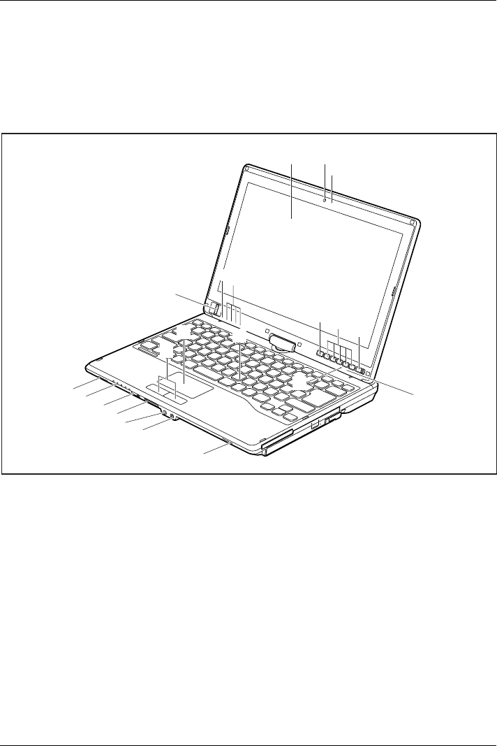
Notebook open
1 2
3
8
6
14
13
12 11
4
6
14
9
5
7
5
15
16
10
17
18
1 = LCD screen
2 = WebCam (optional)
3 = WebCam LED
4 = Fingerprint sensor
5 = Microphone
6 = Status indicators
7 = Windows button
8 = Tablet buttons
9 = ON/OFF switch
10 = Ambient light sensor
11 = Keyboard
12 = Touchpad
13 = Touchpad buttons
14 = Loudspeakers
15 = Microphone jack
16 = Headphone port
17 = Memory card slot
18 = ON/OFF switch for wireless components
Fujitsu 9
Ports and controls
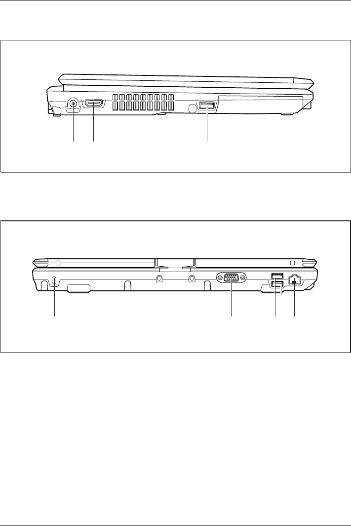
Left panel
1 2 3
1 = DC input connector (DC IN)
2 = HDMI port
3 = USB port with charging function (Anytime
USB charge, USB 3.0)
Rear
3 421
1 = Security Lock device
2 = VGA monitor port
3 = USB ports (USB 2.0)
4 = LAN port
10 Fujitsu
Ports and controls
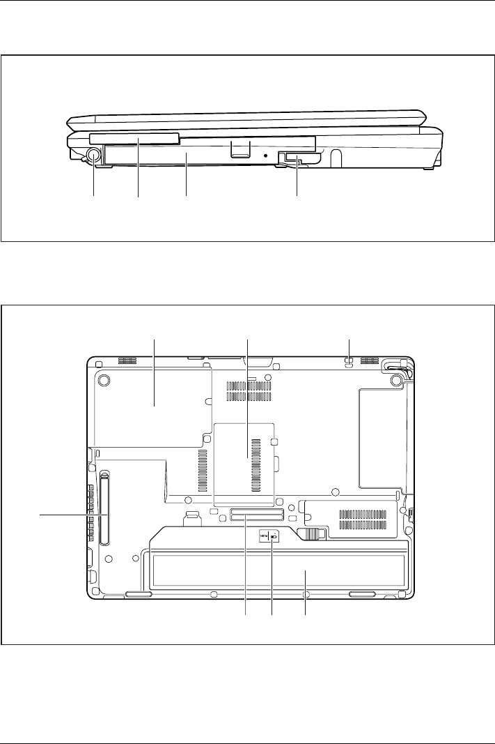
Right-hand side
1 43
2
1=Penslot
2 = ExpressCard slot
3 = Module bay with optical drive
4 = Eject lever for module bay
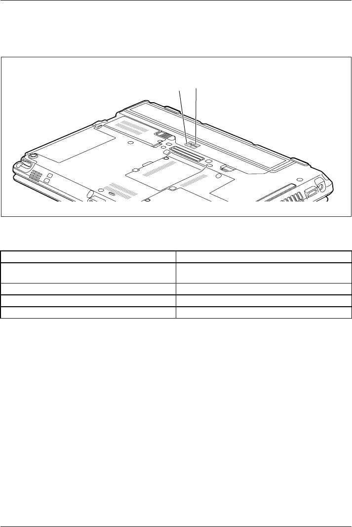
Bottom
1
46
2
7
5
3
1 = Hard disk service compartment
2 = Memory service compartment
3 = Attachment eye for the pen cord
4 = Battery with SIM card slot under the battery
5 = Battery charge status indicator
6 = Port for port replicator
7 = Ventilation slot cover
Fujitsu 11

Important notes
Important notes
ImportantnotesNotes
This chapter contains essential safety information which must be followed
when working with your notebook. Other notes also provide useful information
which will help you with your notebook.
Safety notes
SafetynotesNotes
Please follow the safety notes provided in the "Safety/Regulations" manual
as well as the safety notes given below.
Please pay special attention to the sections in the manual marked
with the symbol on the left.
When connecting and disconnecting cables, observe the relevant
notes in this operating manual.
Read the information on the ambient conditions in the "Technical data",
Page 99 and "First-time setup of your device", Page 15 before preparing your
notebook for use and switching it on for the first time.
When cleaning the device, please observe the relevant notes in the
section "Cleaning the notebook", Page 14.
Pay attention to the additional safety notes for devices with radio components
provided in the "Safety/Regulations" manual.
Please refer to the notes in the chapter "Removing and installing
components during servicing", Page 82.
This notebook complies with the relevant safety regulations for data processing
equipment. If you have questions about using your notebook in a particular area,
please contact your sales outlet or our Hotline/Service Desk.
Additional safety notes for devices with
radio components
Radiocomponent :WirelessLAN:Bluetooth,safetynotes
If a radio component (Wireless LAN, Bluetooth, UMTS/LTE) is incorporated in your notebook,
you must be sure to observe the following safety notes when using your notebook:
• Switch off the radio components when you are in an aircraft or driving in a car.
• Switch off the radio components when you are in a hospital, an operating room or near a medical
electronics system. The transmitted radio waves can impair the operation of medical devices.
• Switch off the radio components when you let the device get near flammable
gases or into hazardous environments (e.g. petrol station, paintshops), as the
transmitted radio waves can cause an explosion or a fire.
For information on how to switch radio components on and off, see chapter
"Switching the wireless components on and off", Page 60.
12 Fujitsu

Important notes
Energy saving
NotesEnergyEnergysaving
Switch the notebook off when it is not in use. Switch off external, connected devices if you
are not using them. If you use the energy saving functions, the notebook uses less energy.
You will then be able to work for longer before having to recharge the battery.
Energy efficiency is increased and the environmental impact is reduced.
You save money while protecting the environment.
Energy saving under Windows
►Make use of the power management features (see ""Using the power-management features",
Page 54").
Travelling with your notebook
MobileoperationNotesTransp ortati onNotebook
Please observe the points listed below when travelling with your notebook.
Before you travel
►Back up important data stored on your hard disk.
NotebookTravel,notebook
►Switch off the radio component for data security reasons. With data traffic via a wireless
connection, it is also possible for unauthorised third parties to receive data.
Information on activating data encryption is provided in the documentation
for your radio component.
►If you wish to use your notebook during a flight, first check with the flight
attendants if it is OK to do so.
When travelling in other countries
►If you are travelling abroad, check that the mains adapter can be operated with the
local mains voltage. If this is not the case, obtain the appropriate mains adapter for
your notebook. Do not use any other voltage converter!
►Check whether the local mains voltage and the power cable are compatible. If this is
not the case, buy a power cable that matches the local conditions.
►Enquire with the corresponding government office of the country you will be
travelling in as to whether you may operate the radio component integrated in your
notebook there (see also "CE marking", Page 102).
Fujitsu 13

Important notes
Notebook: transporting
Protect the notebook from severe shocks and extreme temperatures
(e.g. direct sunlight in a car).
►If your device has an optical drive, remove all data media (e.g. CD, DVD) from the drives.
TransportationNotebook
►Switch the notebook off.
►Unplug the mains adapter and all external devices from the power socket.
►Disconnect the mains adapter cable and the data cables for all external devices.
►Close the LCD screen.
►To protect against damaging jolts and bumps, use a notebook carrying
case to transport your notebook.
Cleaning the notebook
Do not clean any interior parts yourself; leave this job to a service technician.
Only use cleaning products designed for computers. Normal household
cleaners and polishes can damage the markings on the keyboard and the
device, the paintwork or the notebook itself.
Ensure that no liquid enters the notebook.
The LCD screen very sensitive to scratches. Only clean the display
surface with a very soft, slightly damp cloth.
►Switch the notebook off.
CleaningNotesNotebo okKeyboardTouchpadLCDscreenCrystalView display
►In order to prevent accidentially switching the device on, remove the power cable from the mains
adaptor and remove the battery (see "Removing and installing the battery", Page 46).
The surface can be cleaned with a dry cloth. If particularly dirty, use a cloth which has
been moistened in mild domestic detergent and then carefully wrung out.
To clean the keyboard and the touchpad, if available, you can use disinfectant wipes.
Ensure that no liquid enters the device.
14 Fujitsu
First-time setup of your device
First-time setup of your device
First- timese tupGettingstarted
Please read the chapter "Important notes", Page 12.
If your device is equipped with a Windows operating system, the necessary
hardware drivers and supplied software are already pre-installed.
Beforeyouswitchonthedeviceforthefirst time, connect it to the mains voltage
using the mains adapter, see "Mains adapter connecting", Page 16.Themains
adapter must be connected during the entire installation process.
A system test is performed when your device is first switched on. Various messages
can appear. The display may remain dark for a short time or may flicker.
Please follow the instructions on the screen.
NEVER switch off your device during the first-time setup process.
On delivery, the battery can be found in the battery compartment or in the accessories kit.
The battery must be charged if you want to operate your device using the battery.
When used on the move, the built-in battery provides the device with the necessary power. You
can increase the operating time by using the available energy-saving functions.
For instructions on how to connect external devices (e.g. mouse, printer) to your
device, please refer to the operating manual for your device.
Unpacking and checking the device
Should you discover any damage that occurred during transportation,
notify your local sales outlet immediately!
►Unpack all the individual parts.
PackagingTransport
►Check your device for any visible damage which may have occurred during transportation.
You may need the packaging in the future, if you need to transport your device.
Fujitsu 15
First-time setup of your device
Selecting a location
SelectingalocationDeviceMainsad apter
Select a suitable location for the device before setting it up. Follow
the instructions below when doing so:
• Never place the device or the mains adapter on a heat-sensitive surface.
The surface could be damaged as a result.
• Never place the device on a soft surface (e.g. carpeting, upholstered furniture,
bed). This can block the air vents and cause overheating and damage.
• The underside of the device heats up during normal operation. Prolonged contact
with the skin may become unpleasant or even result in burns.
• Place the device on a stable, flat, non-slippery surface. Please note that the
rubber feet of the device may mark certain types of delicate surfaces.
• Keep other objects at least 100 mm away from the device and its
mains adapter to ensure adequate ventilation.
• Never cover the ventilation slots of the device.
• Do not expose the device to extreme environmental conditions. Protect
the device from dust, humidity, and heat.
Mains adapter connecting
Preparingforo perationMainsadapter
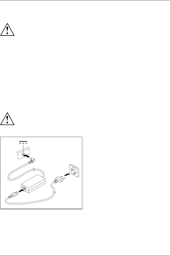
Observe the safety notes in the enclosed "Safety/Regulations" manual.
The supplied power cable conforms to the requirements of the country in
which you purchased your device. Make sure that the power cable is approved
for use in the country in which you intend to use it.
3
1
2
►Connect the power cable (1) to the
mains adapter.
►Plug the mains cable (2) into a mains outlet.
►Connect the mains adapter cable (3) to
the DC jack (DC IN) of the device.
16 Fujitsu
First-time setup of your device
Switching on the device for the first time
Switchingonforthefirstt ime
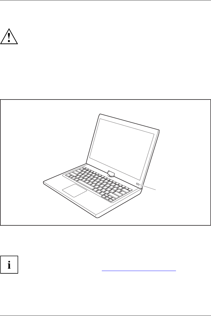
On devices with ON/OFF switch for wireless components: Slide the ON/OFF switch
for wireless components to the ON position before switching on the device.
When you switch on the device for the first time, the supplied software is
installed and configured. Because this procedure must not be interrupted,
you should set aside enough time for it to be fully completed and connect
the device to the mains using the mains adapter.
During the installation process, DO NOT restart the device unless
you are requested to do so!
To make it easier to use your device for the first time, the operating system
is pre-installed on the hard disk.
1
►Slide the ON/OFF switch (1) to the right to switch on the notebook.
The ON/OFF switch returns automatically to its original position.
►During installation, follow the instructions on screen.
If a Windows operating system is installed on your device, you will find more
information on the system and drivers, help programmes, updates, manuals etc. on
the device or on the Internet under "http://www.fujitsu.com/fts/support/".
Fujitsu 17
Working with the notebook
Working with the notebook
Notebook,operati onNotebook
This chapter describes the basics for operating your notebook. Please read the chapter
entitled "Connecting external devices", Page 75 for instructions on how to connect
devices such as a mouse and a printer to the notebook.
Please refer to the notes in "Important notes", Page 12.
Status indicators
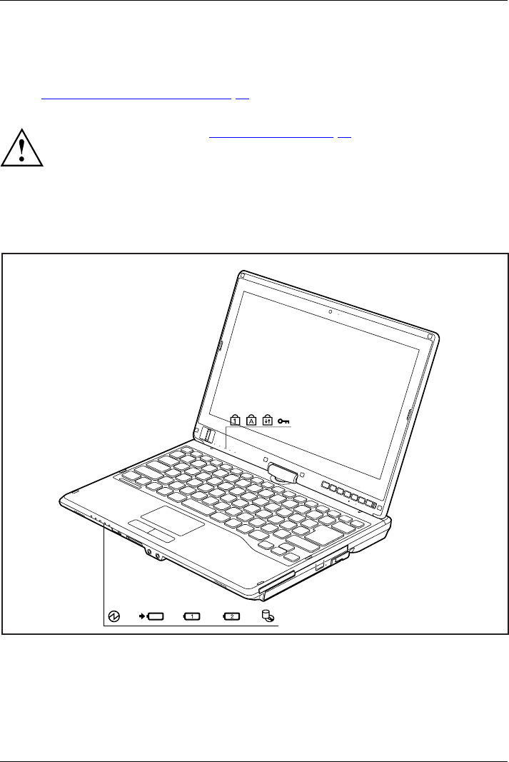
StatusindicatorsSymbols
The status indicators provide information about the status of the power supply,
the drives and the keyboard functions etc.
18 Fujitsu
Working with the notebook
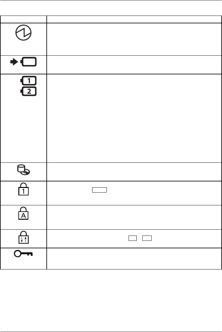
Status displays Description
Power-on indicator
• Indicator is illuminated: The notebook is switched on.
• Indicator flashes: The notebook is in sleep mode (Save-to-RAM).
• The indicator is not illuminated: The notebook is switched off or in
Save-to-Disk mode.
Battery charging indicator
The battery charging indicator shows whether a battery is installed and being
charged.
Battery indicator
This description applies for both batteries.
The battery indicator shows the state of charge of the installed battery.
• The indicator is lit green: The battery is between 51 % and 100 %
charged.
• The indicator is lit orange: The battery is between 13 % and 50 %
charged.
• The indicator is lit red: The battery is between 0 % and 12 % charged.
• The indicator flashes orange: The battery state of charge is being
checked (for four seconds after battery installation).
• The indicator flashes red: The battery is faulty.
• The indicator is not lit: There is no battery installed.
Note: You can also check the state of charge directly at the main battery.
Drive indicator
Indicator is illuminated: The hard disk drive or the CD/DVD in the optical drive
of the notebook is being accessed.
Num Lock indicator
Indicator is lit: The Num key has been pressed. The virtual numerical
keypad is activated. You can output the characters indicated on the upper
rightofthekeys.
Caps Lock indicator
Indicator is lit: The Caps Lock key has been pressed. All letters will be output
as uppercase letters. In the case of keys labelled several times, the character
printed on the upper left of the key will appear when that key is pressed.
Scroll Lock indicator
Indicator is lit: The key combination Fn +Scr has been pressed. The effect
that this key has varies between applications.
Lock Workstation indicator
The indicator is illuminated: The security functions of the Notebook have
locked your workstation.
Fujitsu 19
Working with the notebook
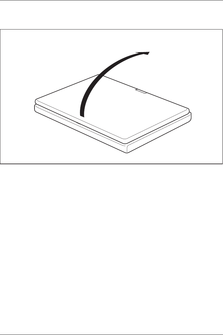
Opening the notebook
1
►Open the LCD screen.
20 Fujitsu
Working with the notebook
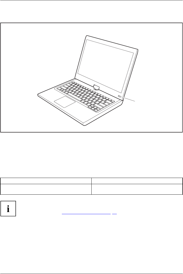
Switching on the notebook
Notebook:sw itching onPower-onindicatorSuspend/Resume button
1
►Slide the ON/OFF switch (1) to the right to switch on the notebook.
The ON/OFF switch returns automatically to its original position.
The ON/OFF switch (1) lights up whenever the system is switched on.
Programming the ON/OFF switch
You can program the ON/OFF switch:
Operating system Menu
Windows 7 Start - (Settings) - Control Panel - System and
Security - Power Options
If you have assigned a password, you must enter this when requested to
do so, in order to start the operating system. Detailed information can be
found in the chapter "Security functions", Page 68.
Fujitsu 21
Working with the notebook
Different ways to use your notebook
During your daily work, you can use your notebook as a tablet PC or as a notebook, just as you wish.
Note the direction of rotation in the following description! No guarantee claims
can be met for damage caused by turning in the wrong direction.
You must note that the display cannot be turned completely on its own axis!
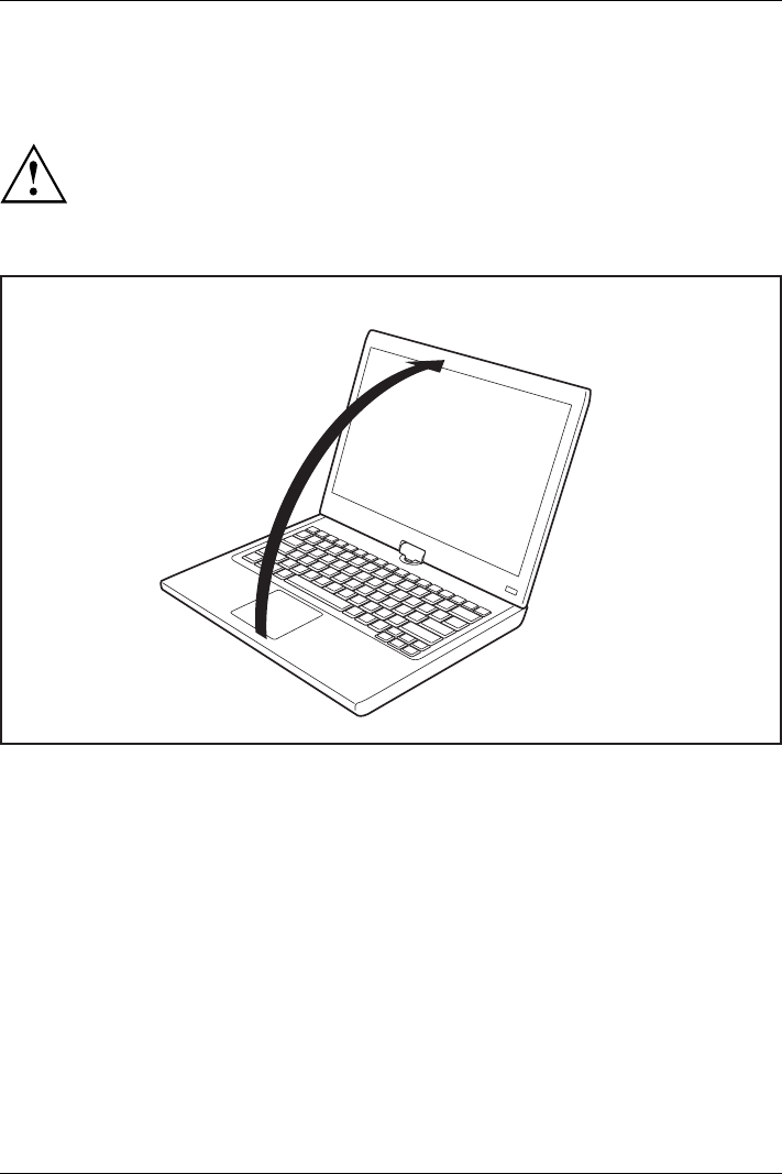
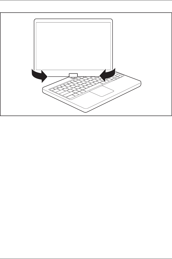
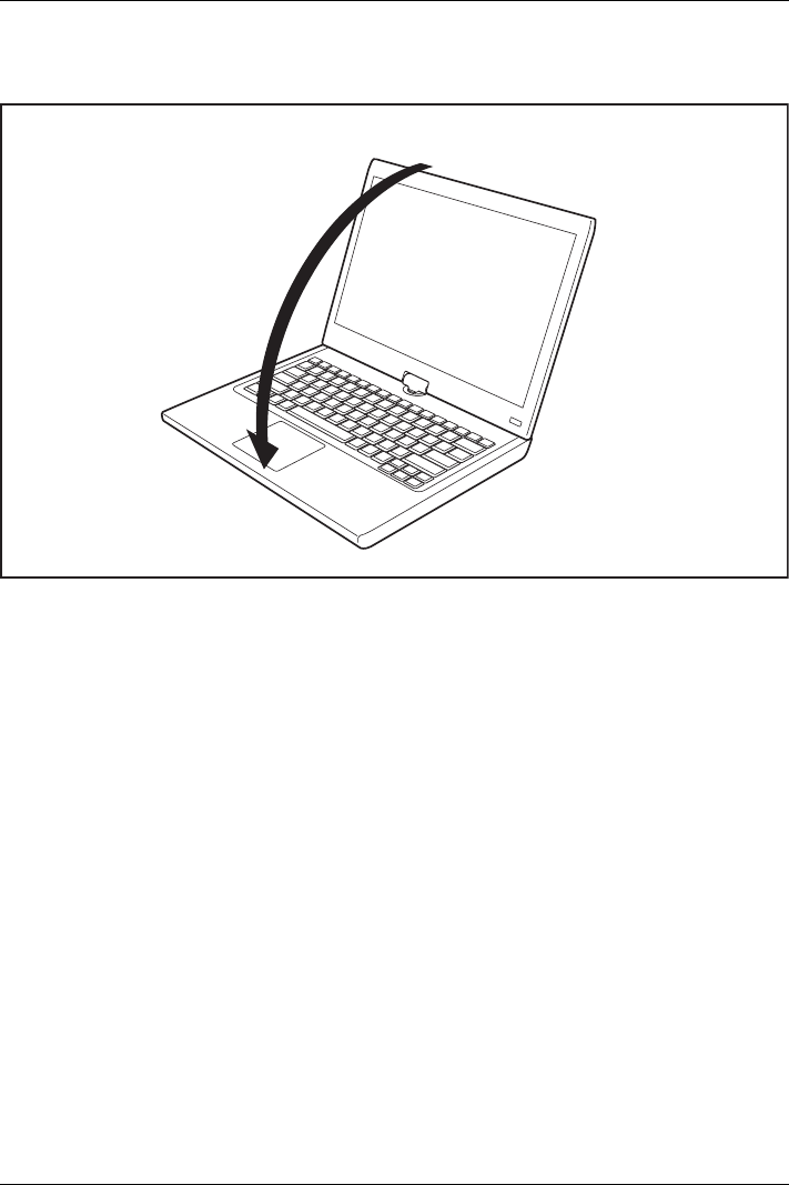
From notebook to Tablet PC
►Raise the LCD display into a vertical position.
22 Fujitsu
Working with the notebook
►Hold the screen as low as possible on both sides. Turn the screen to the left or right in the direction
of the arrow. At first you will feel some slight resistance, then it will turn easily and without friction.
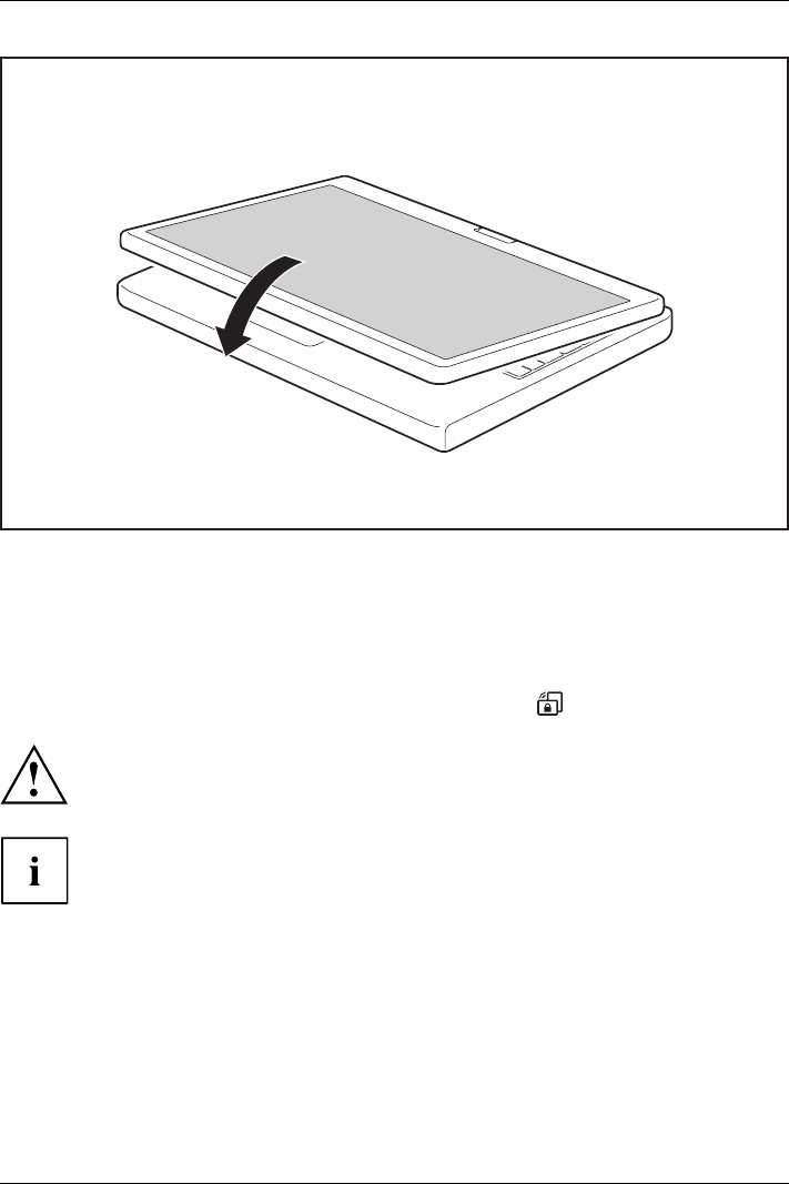
►Turn the display further until it has turned 180° and the hinge latches in.
Fujitsu 23
Working with the notebook
►Now fold the screen down until the back of the screen is flat on top of the keyboard.
The screen is now secured in the tablet position.
Select display orientation (portrait or landscape orientation)
Landscapeorientation
Portraitorientation
Displayorientation
You can choose to use either portrait or landscape orientation for the display. To switch
between portrait or landscape orientation, press the tablet button:
Windows 7
You can change these settings in the Fujitsu menu or under Start -(Settings -)
Control Panel -Hardware and Sound -Display -Settings.
Profiles for operating with various different screen modes can be selected via
the Fujitsu Tablet Control option in the Fujitsu menu. These profiles have preset
standard configurations that can be modified as desired.
These settings do not just affect the monitor settings on the Tablet PC, but
also any external monitors that may be connected.
24 Fujitsu
Working with the notebook
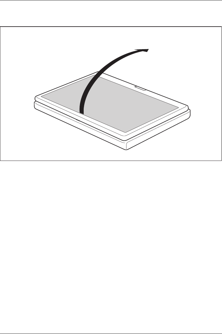
From Tablet PC to notebook
1
►Raise the LCD screen into a vertical position.
Fujitsu 25
Working with the notebook
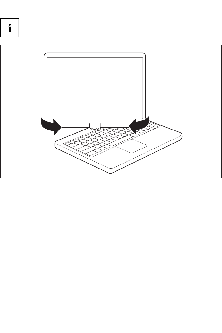
Note the direction of rotation in the following description! No guarantee claims
can be met for damage caused by turning in the wrong direction.
►hold the screen as near to the bottom as possible on both sides and turn the screen in the
direction indicated by the rotational direction indicator. It will turn easily and without resistance.
►Turn or move the display further until it has turned 180° and the hinge latches in.
Switching off the notebook
Notebook
►Close all applications and then shut down the operating system (please
see the "Operating System Manual").
►Slide the ON/OFF switch towards the right.
The ON/OFF switch returns automatically to its original position.
26 Fujitsu
Working with the notebook
Closing the notebook
►Fold the LCD screen down onto the lower part of the notebook until you feel it lock into place.
Handwriting recognition under Windows 7
Handwriting recognition under Windows 7 currently supports the following languages:
English, German, French, Italian, Japanese, Korean, Chinese (traditional and simplified), Dutch,
Portuguese, Spanish, Brazilian, Norwegian (Bokmål and Nynorsk), Swedish, Finnish, Danish,
Polish, Rumanian, Serbian (Cyrillic and Latin script), Catalan, Russian, Czech and Croatian.
Fujitsu 27

Working with the notebook
LCD screen
LCDscreenNotes
High-quality TFT displays are installed in notebooks from Fujitsu Technology Solutions GmbH. For
technical reasons, TFT monitors are manufactured for a specific resolution. An optimal, clear
picture can only be ensured with the correct resolution intended for the relevant TFT monitor. A
monitor resolution which differs from the specification can result in an unclear picture.
The screen resolution of the LCD monitor of your notebook is optimally set at the factory.
The standard of production techniques today cannot guarantee an absolutely fault-free screen
display. A few isolated constant lit or unlit pixels (picture elements) may be present. The maximum
permitted number of pixels faults is stipulated in the international standard ISO 9241-3 (Class II).
Example:
A screen with a resolution of 1280 x 800 has 1280 x 800 = 1024000 pixels. Each pixel consists of
three subpixels (red, green and blue), so there are about 3 million subpixels in total. According to ISO
9241-3 (class II), a maximum of 2 light and 2 dark pixels and in addition 5 light or 10 dark subpixels
or an equivalent mix (1 light subpixel counts as 2 dark subpixels) are allowed to be defective.
At a resolution of 1600 x 900 = 1440000 pixels, a maximum of 3 light and 3 dark pixels
and in addition 7 light or 14 dark subpixels are allowed to be defective.
Pixel A pixel consists of 3 subpixels, normally red, green and
blue. A pixel is the smallest element that can be generated
by complete functionality of the display.
Subpixel A subpixel is a separately addressable internal structure
within a pixel that enhances the pixel function.
Cluster A cluster contains two or more defective pixels or
subpixels in a 5 x 5 pixel block.
Background lighting
TFT monitors are operated with background lighting. The luminosity of the background
lighting can decrease during the period of use of the notebook. However, you can
set the brightness of your monitor individually.
Synchronising the display on the LCD screen and an external monitor
For more information, please refer to the chapter "Key combinations", Page 40
under "Display output, switch between".
Ambient Light Sensor
In the case of delivery with a Windows operating system, the screen brightness is regulated
by means of the ambient light sensor and depending on the particular light conditions. This
results in optimum readability and longer battery life at the same time.
Using a device as a tablet PC
You can execute commands as follows:
• using the stylus pen (supplied with your device).
• using your fingers
28 Fujitsu
Working with the notebook
Using fingers
You can execute certain commands by using your finger tip on the touchscreen of your device.
Everything which you can select or activate using your finger tip can also
be selected or activated using the stylus pen.
Calibrate the Dual Digitizer for finger-based operation of the device.
Please see the appropriate supplementary sheet for instructions on how to
calibrate your device to use Dual Digitizer Technology.
Please note: There are separate calibration programs available for calibrating
the stylus pen and for calibrating finger-based operation. In each case, use the
calibration tool described in the supplementary sheet. Do not use the calibration
tool for the stylus pen to calibrate finger-based operation.
Actions with one finger
Action Description
Selecting objects (click with the left mouse
button)
►With your finger, tap once brieflyonthe
object.
Starting programs (double-click with the left
mouse button)
►With your finger, tap twice briefly in quick
succssion on the program icon.
Moving objects/windows (drag with left mouse
button pressed, Drag & Drop)
►Place a finger directly on the object/window,
hold the finger pressed against the
touchscreen and move the desired
object/window.
Opening a context menu (click with the right
mouse button)
►Touch the desired item once with your finger
tip. Keep the finger tip pressed against the
touchscreen.
The context menu appears.
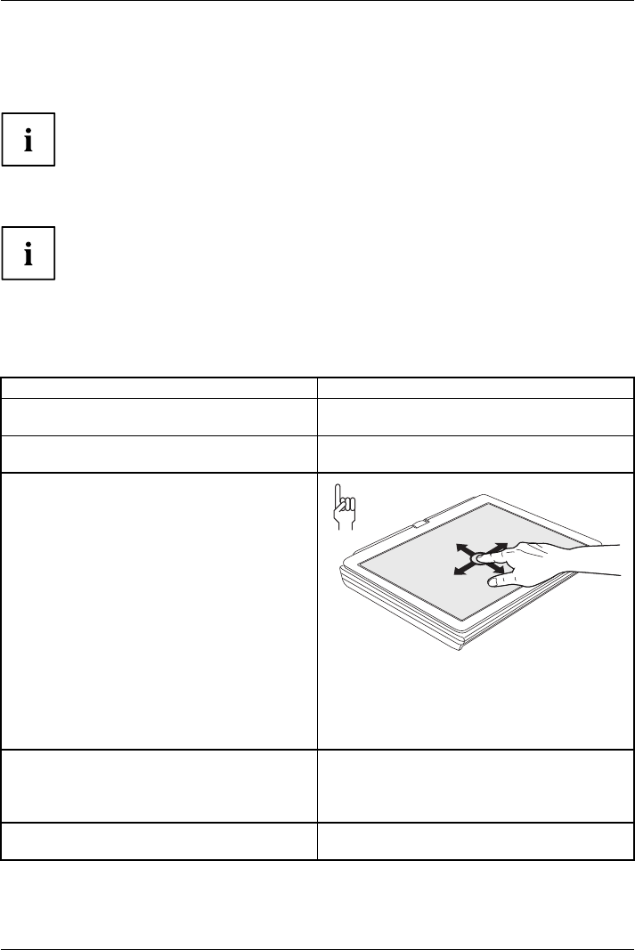
Moving the cursor ►Position one finger on the touchscreen and
move the finger in the desired direction.
Fujitsu 29
Working with the notebook
Actions with two fingers
Action Description
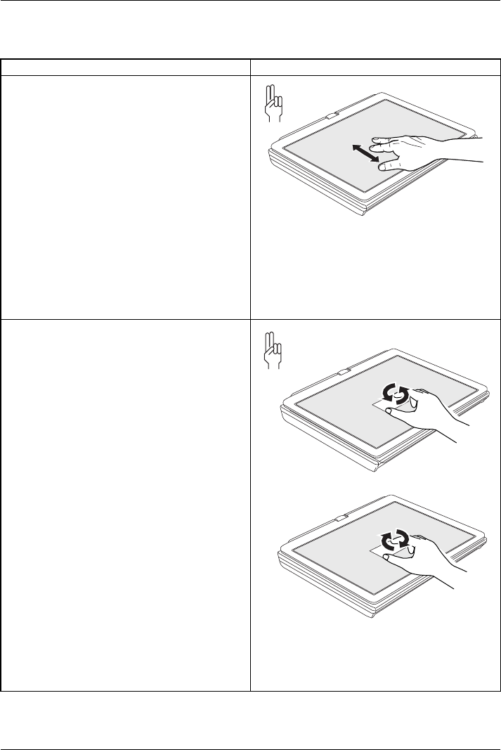
Scrolling
►Position two fingers on the touchscreen.
►Move your fingers upwards to scroll up.
or
►Move your fingers downwards to scroll
down.
Rotating
►Position the thumb on the touchscreen,
then turn the picture clockwise or
counter-clockwise using your index finger.
30 Fujitsu
Working with the notebook
Action Description
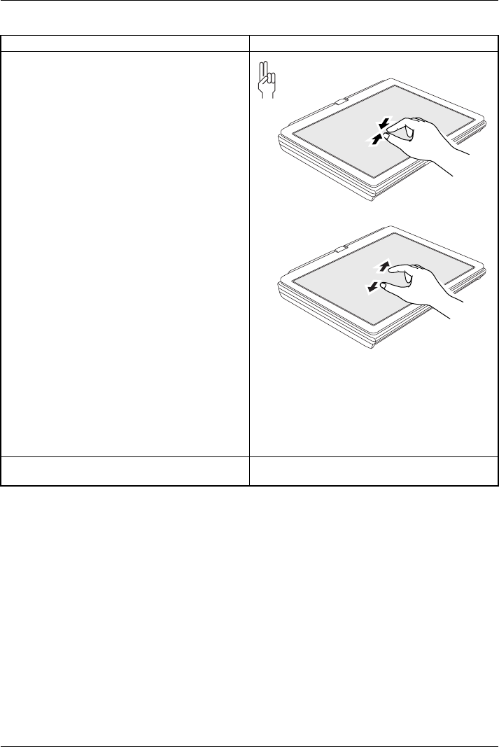
Increasing or decreasing the view
►Position two fingers on the touchscreen and
move them apart to increase the view.
or
►Position two fingers on the touchscreen and
move them together to decrease the view.
Blocking context-sensitive menus ►With two fingers, tap twice briefly in quick
succession on the touchscreen.
Fujitsu 31
Working with the notebook
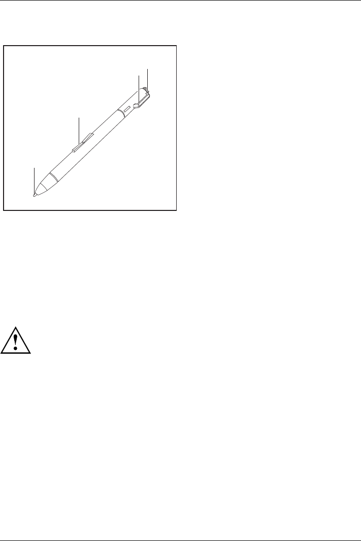
Using the stylus pen
3
1
2
4
1 = pen tip
2 = rocker button
3 = eyelet for pen cord
4 = eraser
You can use the pen on your notebook as an electronic writing implement to select
items and to navigate through menu options and programs. Programs that support
handwriting recognition also allow you to write characters directly on the screen with
the pen. You can also use the pen as a drawing tool.
The notebook pen is retained securely in the pen slot. This ensures that the pen cannot be
lost, regardless of whether you use the notebook as a Tablet PC or as a notebook, or transport
it while travelling. Always replace the pen in its slot when you are not using it.
The notebook is supplied with a pen cord which you can attach to the eyelets
on the pen and on the notebook.
Only use the pen provided with your notebook. Do not use substitute pen tips
that were not specially designed for your notebook. Replace the stylus tip if it
is worn. The warranty does not cover a scratched screen.
While writing, you should take care not to scratch the surface of the
display (e.g. with a wristwatch or bracelet).
32 Fujitsu

Working with the notebook
The pen of your notebook is an electronic instrument which can be damaged
if used incorrectly. Handle the pen with care.
The following list contains guidelines for proper pen handling:
• Do not gesture with the pen.
• Do not use the pen as a pointer.
• Never use the pen on any other surface than the screen of your notebook.
• Do not try to turn the thumb grip on the pen. The thumb grip is used to
place the pen in its slot and to take it out of the slot.
• Never store the pen with the tip bearing the weight of the pen (e.g. with the tip down
in a pen holder). If the pen is stored with the tip pointing down, this may have
an adverse effect on the pen mechanism (particularly under high temperatures).
In this case the pen tip may react as though it is constantly being pressed down.
To avoid damage, the pen should be stored in the pen slot when not in use.
Thepencanbeinfluenced by electromagnetic fields (cursor quivers or
jumps). There may be a few areas on the screen where the cursor quivers
slightly in spite of pressing the pen down firmly.
The screen responds to entries made with the tip of the finger or the pen when the tip
of the finger or the pen is in direct contact with the screen.
You can use the pen to perform all the functions for which you would otherwise use a mouse.
In addition, you can conveniently delete hand-written pen entries using the pen.
Handling Mouse Pen
Selecting menu
entries
Click with the left-hand mouse button. Touch the menu entry with the pen tip.
Starting programs Double click with the left-hand mouse
button.
Briefly touch the program icon twice
with the pen tip.
Moving
objects/windows
Drag with the left-hand mouse button
held pressed.
Place the pen tip directly on the
object/window. Hold the pen tip
pressed against the screen. Move the
desired object/window.
Opening a context
menu
Click with the right-hand mouse
button.
Touch the desired element with the
pen and leave the pen on the element
for a moment.
Moving the cursor -Place the pen tip directly on the
screen.
Setting the pen
Operating system Menu
Windows 7 Under Hardware and Sound – Pen and Input Devices in the Control Panel
you can change various settings for the pen (assignment and function of
the pen button).
Fujitsu 33
Working with the notebook
Calibrating the pen
Before using the pen for the first time, you should calibrate it so that the cursor follows the
movements of the pen as accurately as possible. You should also always repeat the calibration
if the co-ordination between the pen and cursor movement deteriorates.
Operating system Menu
Windows 7 To calibrate, call up the Hardware and Sound / Tablet PC Settings function
in the Control Panel. You need to calibrate both portrait and landscape
formats.
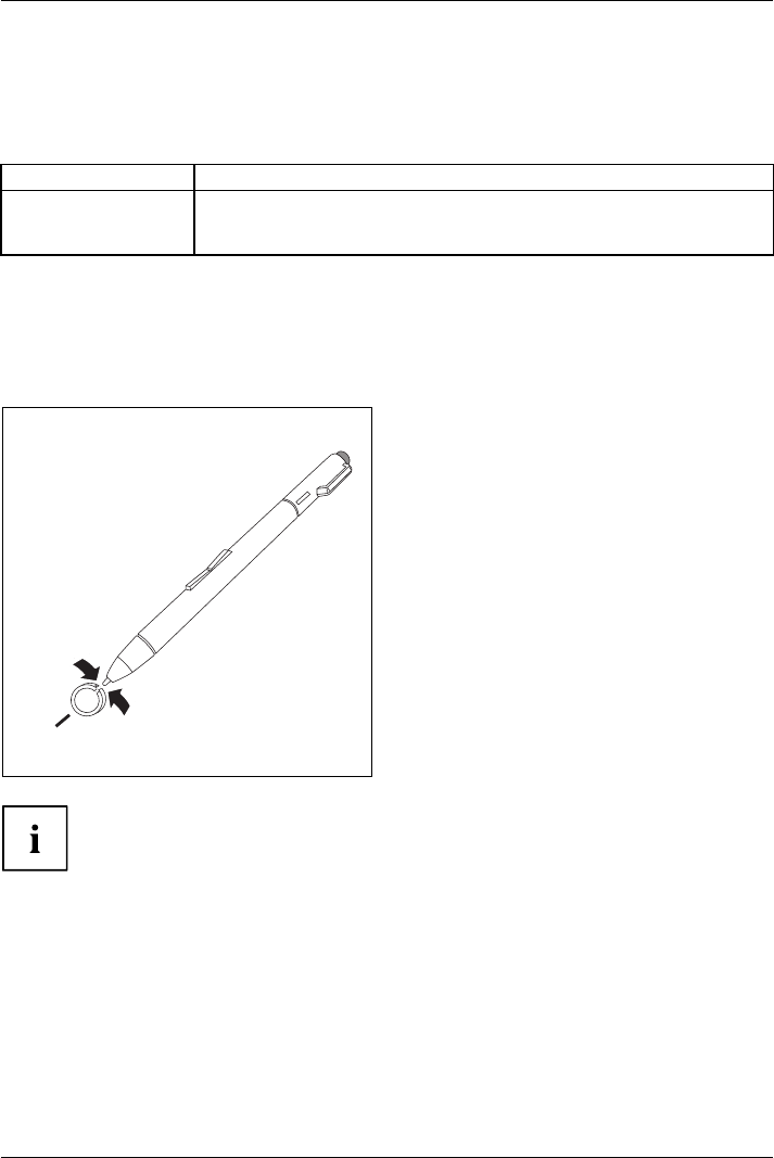
Replacing the pen tip
With use, the pen tip may become worn or may pick up foreign particles that can scratch the screen.
A damaged or worn tip may not move freely, causing unpredictable results when using the pen.
If your pen exhibits these problems, you should replace the pen tip. To do this, use the supplied tool (1).
1
►To remove the tip, position the tip in the gap
between the two ends of the tool supplied.
►Pinch the two ends of the supplied tool
together so that thetipisfirmly clasped,
then pull it from the barrel.
►To replace the tip, retrieve one of the
new tips that were supplied your pen.
Insert the flat end of the tip into the
barrel and exerting gentle pressure, push
it in until it is firmly in place.
If the tip is worn or damaged, discard it.
Installing a pen cord
You should attach the pen with a pen cord to prevent accidentally dropping or losing it.
►Attach the end of the pen cord with the smaller loop to your pen.
►Attach the end of the pen cord with the larger loop to your notebook.
34 Fujitsu
Working with the notebook
Using the device as a notebook
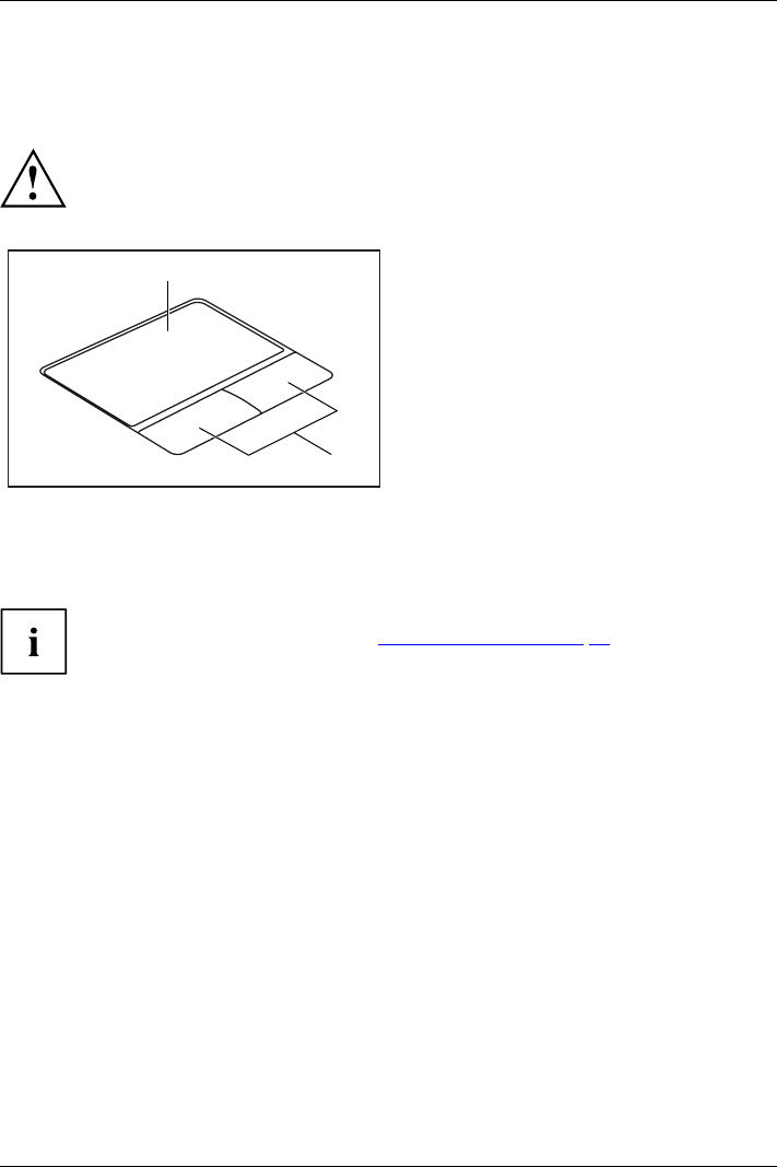
Touchpad and touchpad buttons
Keep the touchpad clean. Protect it from dirt, liquids and grease.
TouchpadTouchpad
Do not use the touchpad if your fingers are dirty.
Do not rest heavy objects (e.g. books) on the touchpad or the touchpad buttons.
1
2
1 = Touchpad
2 = Touchpad buttons
The touchpad enables you to move the mouse pointer on the screen.
The touchpad buttons allow you to select and execute commands. They correspond
to the buttons on a conventional mouse.
You can use a key combination to disable the touchpad, to avoid accidentally moving
the pointer on the screen (see also "Key combinations", Page 40).
Moving the pointer
►Move your finger on the touchpad.
Touchpad
The pointer will move.
Selecting anitem
►Move the pointer to the item you wish to select.
Touchpad
►Ta p t h e t o uchpad once or press the left button once.
The item is selected.
Executing commands
►Move the pointer to the field you wish to select.
Tou chp ad
►Ta p t h e touchpad twice or press the left button twice.
The command is executed.
Fujitsu 35

Working with the notebook
Dragging items
►Select the desired item.
Touchpad
►Press and hold the left button and drag the item to the desired position
with the finger on the touchpad.
The item will be moved.
Switching the Touchpad on and off
You can switch the Touchpad on and off using a key combination,
see "Key combinations", Page 40.
36 Fujitsu
Working with the notebook
Keyboard
KeyboardNumerickeypadNumeric keypadButtons
The keyboard of your notebook is subject to continuous wear through normal
use. The key markings are especially prone to wear. The key markings are
liable to wear away over the life of the notebook.
The keyboard has been designed to provide all the functions of an enhanced keyboard.
Some enhanced keyboard functions are mapped with key combinations.
The following description of keys refers to Windows. Additional functions supported by the keys
are described in the relevant manuals supplied with your application programs.
The figure below shows how to access the different characters on keys with overlaid functions.
The example applies when the Caps Lock key has not been activated.
The illustrations shown below may differ from your actual device.
0
=
}
+
+
Num
Alt Gr
=
0}
=
0}
=
0}
=
0}
Fujitsu 37
Working with the notebook
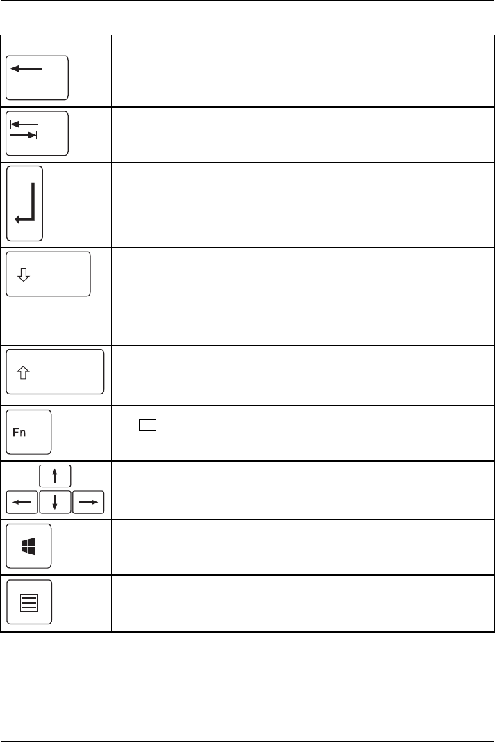
Key Description
Backspace key
The Backspace key deletes the character to the left of the cursor.
BackspaceBac kspace
Tab key
The Tab key moves the cursor to the next tab stop.
Tabkey
Enter key (return)
The Enter key terminates a command line. The command you have entered
is executed when you press this key.
EnterkeyReturnEnterLine feed
Caps Lock key
The Caps Lock key activates the Caps Lock mode, and the corresponding
icon is displayed in the Windows information area. In Caps Lock mode, all
of the characters you type appear in upper case. In the case of overlay
keys, the character printed on the upper left of the key will appear when
that key is pressed. To cancel the Caps Lock function, simply press the
Caps Lock key again.
ShiftkeyCapsLock
Shift key
The Shift key causes uppercase characters to appear. In the case of overlay
keys, the character printed on the upper left of the key appears when that
keyispressed.
ShiftkeyShift
Fn button
The Fn key enables the special functions indicated on overlay keys (see
"Key combinations", Page 40).
Fnkey
Cursor keys
The cursor keys move the cursor in the direction of the arrow, i.e. up, down,
left, or right.
CursorkeysCursorcontrolkeys
Start key
The Start key opens the Windows Start menu.
Startkey
Menu key
The Menu key invokes the menu for the marked item.
38 Fujitsu
Working with the notebook
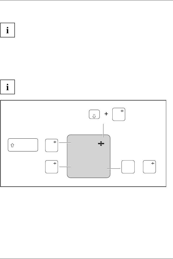
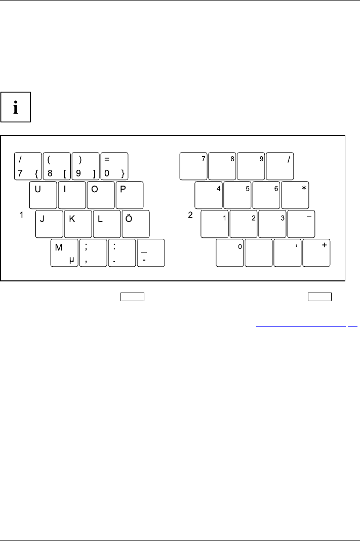
Virtual numeric keypad
NumerickeypadVirtu alnum eric keypadNumLock
To provide the convenience of a numeric keypad, your keyboard is equipped with a virtual
numeric keypad. The special keys of the virtual numeric keypad are recognisable by the numbers
and symbols printed in the upper right corner of each key. If you have switched on the virtual
numeric keypad, you can output the characters shown on the upper right of the keys.
The keyboard layout shown below may differ from your actual device.
1 = Valid characters when the Num
key is not activated
2 = Valid characters when the Num
is activated
Further information about the status indicators can be found in chapter "Status indicators", Page 18.
Country and keyboard settings
If you want to change the country and keyboard settings, proceed as follows:
►Enter the settings by clicking Start – (Settings) – Control Panel – Time, Regional and Language Options.
Fujitsu 39
Working with the notebook
Key combinations
The key combinations described below apply when using Microsoft Windows
operating systems. Some of the following key combinations may not function in
other operating systems or with certain device drivers.
Key combinations are entered as follows:
►Press the first key in the combination and keep it pressed.
►While holding the first key down, press the other key or keys in the combination.
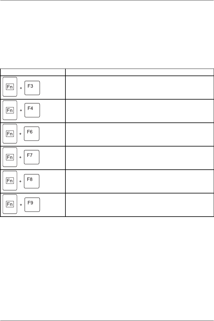
Combination Description
Switching the loudspeakers on/off
This key combination switches the integrated loudspeakers on and
off.
Fn+F3Louds peakerLoudspeaker
Enable/disable touchpad
This key combination enables and disables the touchpad.
Fn+F4TouchpadTouchpadbuttonsTouchpad
Decrease screen brightness
This key combination decreases the brightness of the screen.
Fn+F6LCDscreenScreenbrightn ess
Increase screen brightness
This key combination increases the brightness of the screen.
Fn+F7Scre enbrightness
Decrease volume
This key combination reduces the volume of the internal
loudspeakers.
Fn+F8Volume
Increase volume
This key combination increases the volume of the internal
loudspeakers.
Fn+F9Volume
40 Fujitsu
Working with the notebook
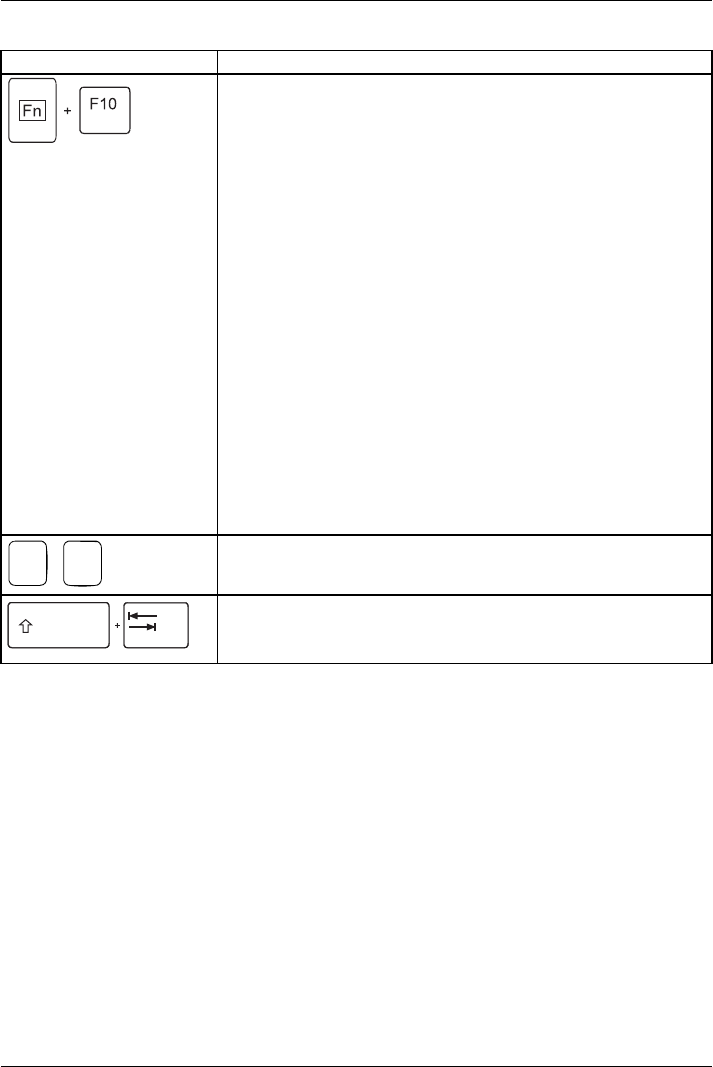
Combination Description
Toggle output screen
Fn+F10Toggleoutputs creen
Use this key combination to select which screen(s) is/are used for
display if an external monitor is connected.
Screen output is possible:
• only on the notebook’s LCD screen
• only on the external monitor
• on the notebook’s LCD screen and the external monitor at the
same time.
Press the key combination several times to switch through all
possible settings.
It is possible to display video on two screens simultaneously,
regardless of the type and number of external screens connected.
If you have connected two external monitors to the port replicator,
the following display outputs are possible:
• only on the notebook’s LCD screen
• only on the external monitor (analogue)
• at the same time on the LCD screen (digital)
• at the same time on the notebook’s LCD screen and on the
external monitor (analogue)
You cannot use the key combination to switch output at the same
time to both external monitors on the Port Replicator.
+
Ctrl CHalt current operation
This key combination can be used to halt an operation instantly
without clearing the keyboard buffer.
Back tab
This key combination moves the cursor back to the previous tab
stop.
Shift+TabTabback
Fujitsu 41
Working with the notebook
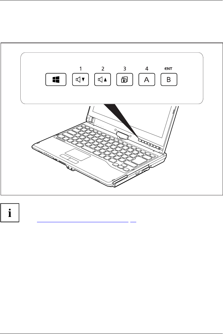
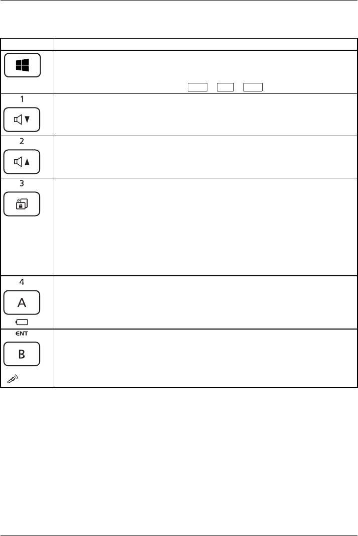
Tablet buttons
Your notebook has six multifunctional tablet buttons. You can navigate on the screen with a
simple press of a button, call preset applications or ones that you have set yourself.
The tablet buttons have different uses in different modes.
In addition, you can still individually program some of the tablet buttons,
see "Programming the tablet buttons", Page 43.
42 Fujitsu
Working with the notebook
Basic functions when the device has booted
Button Basic function
Windows button
This button corresponds to the function of the Windows Start key on a keyboard.
If the button is pressed in combination with the ON/OFF switch, the function
corresponds to the key combination Ctrl +Alt +Del .
Decrease volume
This button reduces the volume of the built-in loudspeakers.
Increase volume
This button increases the volume of the built-in loudspeakers.
Rotation Lock
When you press this button, the orientation of the screen display changes from
portrait (vertical) to landscape (horizontal) or vice versa.
When you would like to use the Tablet PC as an eBook, for example, you would
use the portrait orientation.
When accessing spreadsheets, you would more typically use a landscape
orientation.
Windows 7:
This button locks and unlocks the automatic rotation of the display.
Button "A"
This button starts the Fujitsu Menu application. You can use this application to
change certain system settings.
The button is freely programmable.
Button "B"
Use this button to start the Windows Journal.
The button is freely programmable.
Programming the tablet buttons
You can program the tablet buttons to open a specific application or execute
a specific function when pressed.
Proceed as follows:
►In Control Panel, select the option to manage the settings for the tablet buttons and pen.
►Follow the instructions on the screen and program the tablet buttons as you require.
Fujitsu 43

Working with the notebook
Webcam
Webcam
Depending on the software used, you can use your Webcam to take pictures,
record video clips or take part in web chats.
• The picture quality depends on the lighting conditions and the software being used.
• You can only operate the webcam with a particular application (e.g. an Internet telephony
program or a video conferencing program which supports a webcam).
• When using the webcam the notebook support must not wobble.
• The webcam automatically adjusts itself to the current light level. For this reason
the LCD screen may flicker while the light level is adjusted.
Further information on using the webcam and on the additional settings
which are possible for your webcam can be found in the help function
of the program which uses the webcam.
If you would like to perform a function test of your web cam, there is suitable test
software available at "http://www.fujitsu.com/fts/support/index.html".
44 Fujitsu
Working with the notebook
Rechargeable battery
RechargeablebatteryBatteryLife,batteryRechargeablebatteryRechargeablebattery
When not plugged into a mains socket, the notebook runs on its built-in battery. You
can increase the life of the battery by caring for the battery properly. The average
battery life is around 500 charge/discharge cycles.
You can extend the battery life by taking advantage of the available energy saving functions.
Charging, caring for and maintaining the battery
BatteryBattery
The notebook battery can only be charged, when the ambient temperature
is between 5°C and max. 35°C.
You can charge the battery by connecting the notebook to the mains adapter
(see "Mains adapter connecting", Page 16).
If the battery is running low you will hear a warning alarm. If you do not connect the mains adapter
within five minutes of the warning alarm described above, your notebook will automatically switch off.
monitoring the battery charging level
BatteryBatterystatusmeter
Windows also has a "Battery status meter" in the taskbar for monitoring the battery capacity. When
you place the mouse pointer on the battery symbol, the system displays the battery status.
The battery capacity can be monitored using an indicator which shows the current state
of charge. Use the following menu to enable this feature:
Operating system Menu
Windows 7 Start – (Settings) – Control panel – Mobile PC –
Power options
Battery storage
BatteryBatterySelf-discharge,battery
Chargingcapacity, battery
Keep the battery pack between 0°C and +30°C. The lower the temperature at which
the batteries are stored, the lower the rate of self-discharge.
If you will be storing batteries for a longer period (longer than two months),
the battery charge level should be approx. 30 %. To prevent exhaustive
discharge which would permanently damage the battery, check the level
of charge of the battery at regular intervals.
To be able to make use of the optimal charging capacity of the batteries, the battery
should be completely discharged and then fully recharged.
If you do not use the batteries for long periods, remove them from the
notebook. Never store the batteries in the device.
Fujitsu 45
Working with the notebook
Removing and installing the battery
Only use rechargeable batteries approved by Fujitsu Technology
Solutions for your notebook.
Never use force when fitting or removing a battery.
Make sure that no foreign bodies get into the battery connections.
Never store a battery for longer periods in the discharged state. This
can make it impossible to recharge.
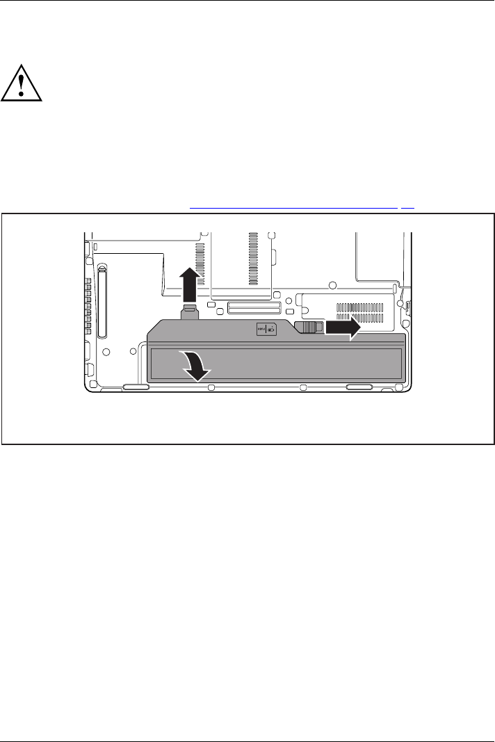
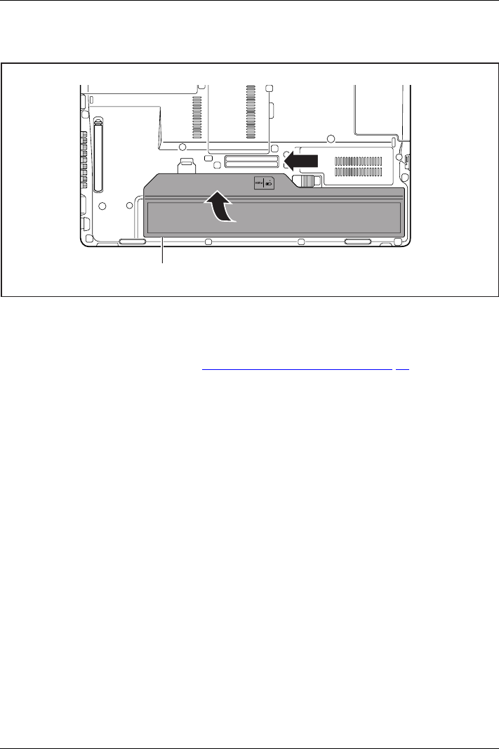
Removing the battery
►Prepare for removal, see chapter "Preparing to remove components", Page 83.
2
1
3
►Slide the release button (1) in direction of the arrow.
►Slide the release button (2) in direction of the arrow.
►Lift the battery out of the battery compartment (3).
46 Fujitsu
Working with the notebook
Inserting battery
2
3
1
►Place the battery on the lower edge of the battery compartment (1).
►Slide the battery into the battery compartment until you feel it engage (2).
►Slide the release button into its locked position (3).
►Complete the removal, see chapter "Finishing component removal", Page 89.
Fujitsu 47
Working with the notebook
Batterychargestatusindicator
You can check the charge status directly on the battery itself.
11
a
►Press the key (1).
The LED (a) lights up in one of the following colours:
LED indicator State of charge
Green The battery is between 50 % and 100 %
charged.
Orange The battery is between 11 % and 49 % charged.
Red The battery is between 1 % and 10 % charged.
LED not lit The battery is fully discharged.
48 Fujitsu
Working with the notebook
Module
ModulebayModules
The design of your notebook enables the flexible use of notebook batteries and drives. The
following modules can be operated in the module bay of your notebook:
• Second battery
• Optical drive
• Empty plug-in unit (save weight)
Only use modules designed for your notebook.
Do not use force when installing or removing the module.
Make sure that no foreign objects enter the module bay.
You can swap modules during operation. This means you do not
need to switch off the notebook.
To replace a module, simply click on the corresponding icon in the
task bar and then on Exit or Select - Exit.
The module can now be removed without any further actions being necessary.
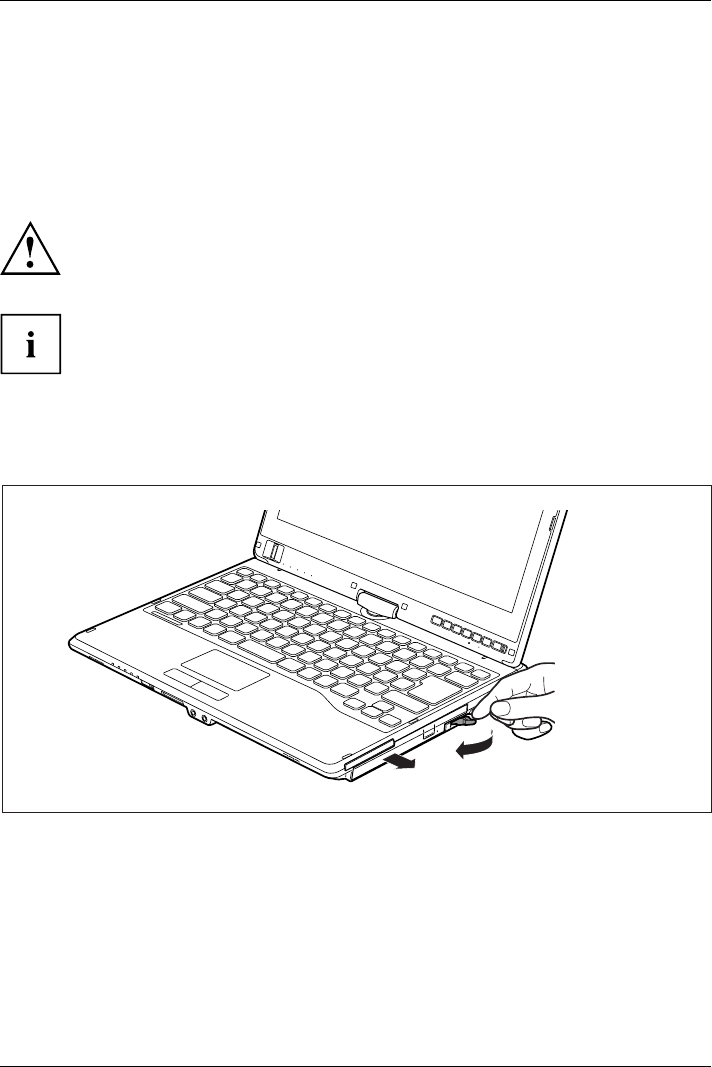
Removing a module
1
2
ModuleDriveWeight Saver
►Slide the release lever in the direction of the arrow (1).
►Now pull the module out of the module bay (2).
Fujitsu 49
Working with the notebook
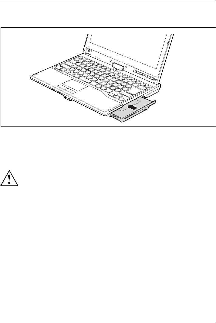
Installing a module
►Place the module into the module bay so that the contacts enter first.
►Push the module into the module bay until you feel it locking into place.
Optical drive
Opticaldrive
This product contains a light emitting diode, classification according to IEC 60825
1:2007: LASER CLASS 1, and must therefore not be opened.
Handling data carriers
Handling
Observe the following guidelines when handling data carriers:
• Avoid touching the surface of a data carrier. Only handle data carriers by their edges.
• Always store data carriers in their cases. This will protect the data carrier against
being covered in dust, scratched or damaged in any other way.
• Protect your data carriers against dust, mechanical vibrations and direct sunlight.
• Avoid storing a data carrier in areas subject to high temperatures or humidity.
You may use both 8-cm and 12-cm data carriers in the optical drive.
When using a data carrier of lesser quality, vibrations and reading errors may occur.
50 Fujitsu
Working with the notebook
CD/DVD indicator
CD/DVDindicator
The CD/DVD indicator flashes when a data carrier is inserted. The indicator goes out when
the drive is ready for reading. The indicator lights up when the drive is being accessed.
You may only remove the data carrier when the indicator is unlit.
If the CD/DVD indicator does not go out after a data carrier has been inserted, but
instead continues to flash, this means that the drive cannot access the data carrier.
Either the data carrier is damaged or dirty or you are using a data
carrier that the drive cannot read.
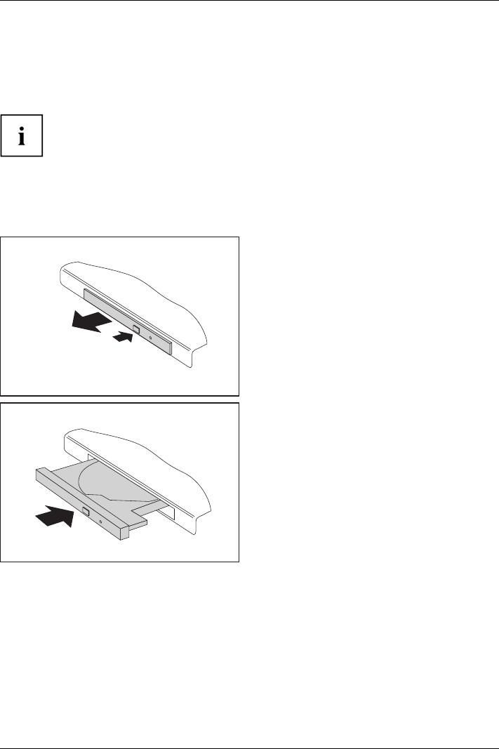
Inserting or removing a data carrier
InsertingRemoving
The notebook must be switched on.
2
1
►Push the insert/eject button (1).
The drive tray will open.
►Gently pull the drive tray (2) completely out.
►Place the data carrier in the drive tray with
the printed side facing upwards.
or
►Remove a data carrier that has
been inserted.
►Push in the drive tray until you
feel it lock into place.
Fujitsu 51
Working with the notebook
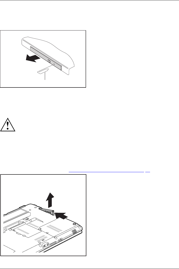
Manual removal (emergency removal)
CD/DVD:ManualremovalofdatacarrierEmergencyrem ovalo fdata carrier
In the event of a power failure or damage to the drive, you can remove the data carrier manually.
1
2
►Switch your notebook off.
►Push a pen or a piece of wire (such as a
paperclip) firmly into the opening (1).
The drive tray is ejected. You can now pull
the drive tray (2) out of the drive.
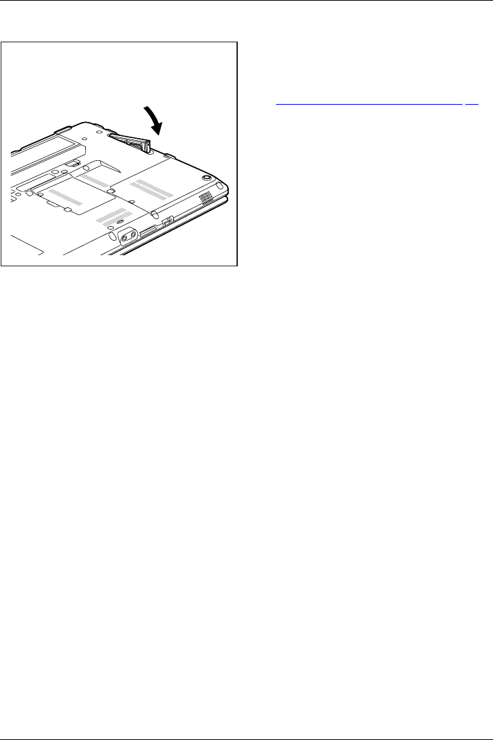
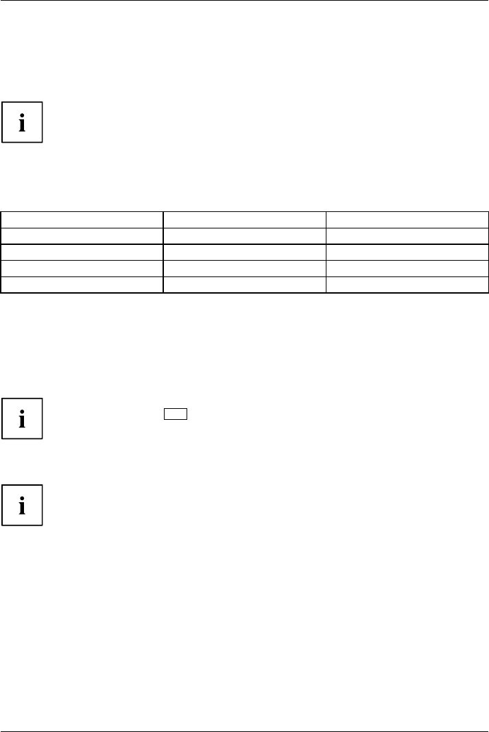
Removing and fitting the dust removal cover
(ventilation slot cover)
In order to ensure optimum cooling of the components in your notebook, you
should periodically clean the ventilation slot of the heatsink.
This ensures optimum fan performance. You can achieve the best cleaning
results with a small hand-held vacuum cleaner.
If necessary, you can also use a dry brush to release dust from the ventilation slots.
Do not use any cleaning liquids! Ensure that no liquid enters the device.
To avoid overheating of the device, do not remove the ventilation slot
cover when the device is switched on.
►Prepare for removal, see chapter "Preparing to remove components", Page 83.
1
2
►Press and hold the lock of the ventilation
slot cover (1) and remove it from its slot (2).
►Clean the dust chamber.
52 Fujitsu
Working with the notebook
Using the power-management features
PowerPowerBattery
The notebook uses less power when the available power-management features are used. You
will then be able to work longer when using the battery before having to recharge it.
Power efficiency is increased and environmental pollution reduced. By
choosing the best power options, you can make significant savings and
at the same time help protect the environment.
When you close the LCD screen, depending on the setting in Windows, the
notebook automatically enters a power saving mode.
We recommend the following settings:
Function On external power On battery power
Turn off monitor After 10 minutes After 5 minutes
Turn off hard disk(s) After 15 minutes After 10 minutes
Energy saving (S3) After 20 minutes After 15 minutes
Hibernate mode (S4) After 1 hour After 30 minutes
►Select the power management functions in your Control Panel.
►Select the Screen Saver in your Control Panel.
or
►Right-click on the desktop. Switch on the screen saver by clicking Personalization –
Change screen saver.
If you need further information about an option, you can get help with most
settings by pressing F1 to open the Microsoft Help.
When the notebook is in power-saving mode, the following must be remembered:
During power saving mode, open files are held in the main memory
orinaswapfile on the hard disk.
Never turn off your notebook while it is in a power saving mode. If the built-in battery is
nearly empty, close the open files and do not go into power saving mode.
If you do not intend to use your notebook for a long period of time:
►Exit power saving mode if necessary via the mouse or keyboard or by switching on the
notebook.
►Close all opened programs and completely shut down the notebook.
54 Fujitsu
Working with the notebook
Memory cards
Slot
Your notebook is equipped with an integrated memory card reader.
Observe the manufacturer’s instructions when handling the memory cards.
Memorycard
Supported format
The memory card reader supports the following format:
• Secure Digital (SDTM card)
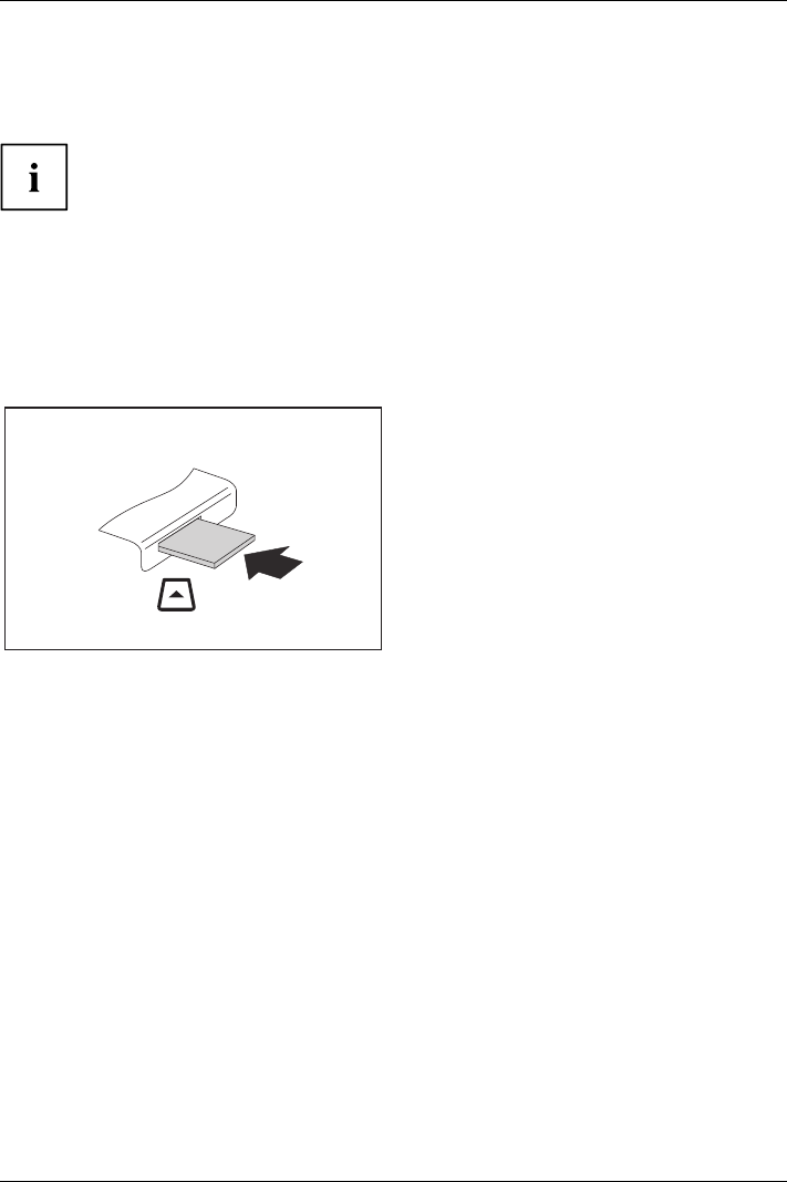
Inserting the memory card
►Carefully slide the memory card into the
slot. The label should be facing upward. Do
not apply excessive force, as otherwise the
delicate contact surfaces could be damaged.
Memorycard
Depending on the particular type
used, the memory card may protrude
slightly from the slot.
Fujitsu 55
Working with the notebook
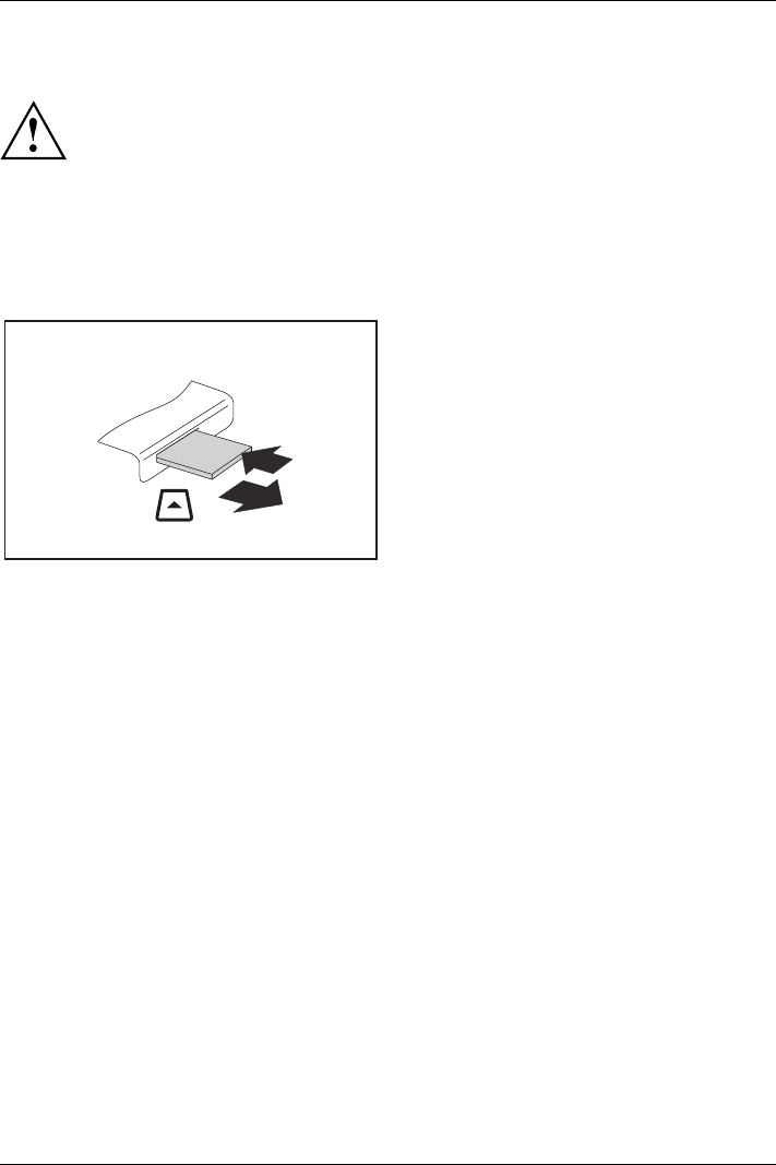
Removing the memory card
Memorycard
In order to protect your data, always follow the correct procedure
for removing the card outlined below.
You can stop the memory card via the corresponding icon in the task bar:
►Left-click on the icon.
►Select the card you want to stop and remove.
►Press the Enter key.
Wait for the dialogue box which tells you that it is now safe to remove the memory card.
1
2
►On devices with card locking: Press
on the storage card (1).
Memorycard
The storage card is released and
can now be removed.
►Pull the storage card out of the slot (2).
56 Fujitsu
Working with the notebook
ExpressCards
SlotExpressCar d
An ExpressCard slot allows an ExpressCard/54 to be used with the computer.
Consult the documentation supplied by the ExpressCard’s manufacturer
and follow the instructions provided.
Never use force when installing or removing an ExpressCard.
Make sure that no foreign objects enter the ExpressCard slot.
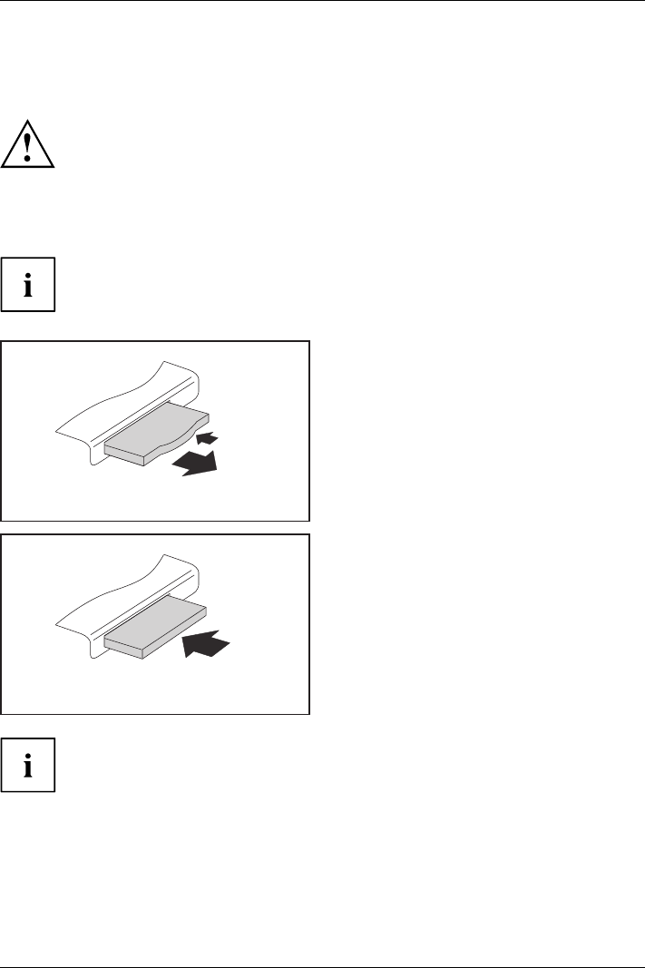
Inserting the card
Keep the placeholder for the slot in a safe place. When you remove the card again, you
must reinstall the place holder. This prevents foreign objects from getting into the slot.
1
2
►Press the edge of the placeholder (1)
to make the card placeholder protrude
from the notebook’s case.
►Pullthecardplac
eholder out of the slot (2).
►Insert the card into the slot guide with
the connection contacts first.
►Gently push the card into the slot until you
feel it click into place. Do not use any force.
Depending on the particular type used, the
card may protrude slightly from the slot.
Please see the documentation relating to the card for driver installation instructions.
Fujitsu 57
Working with the notebook
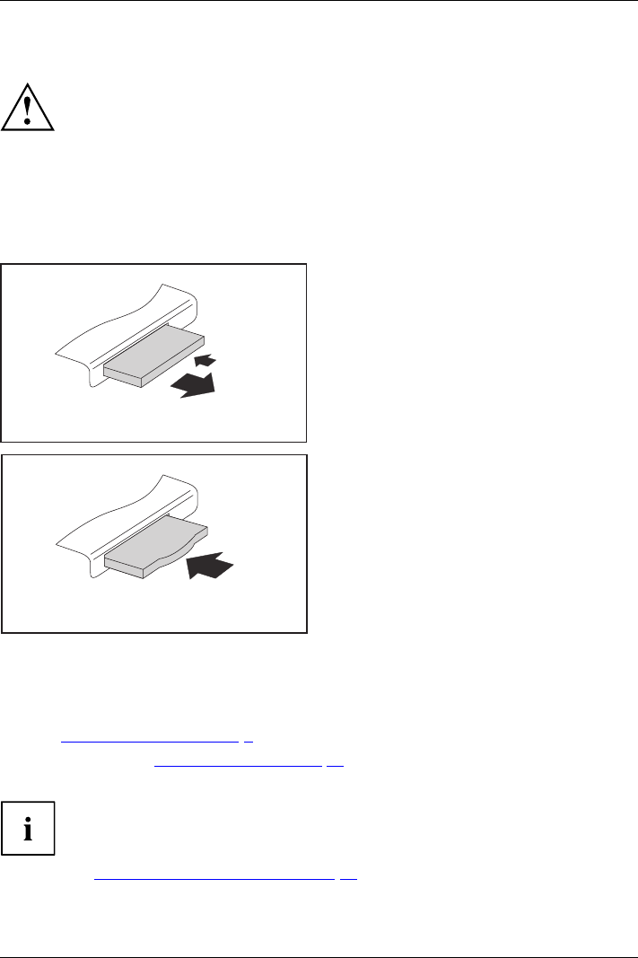
Removing the card
Always remove the card according to the rules described below, to
ensure that none of your data is lost.
You can stop the ExpressCard using the corresponding symbol in the task bar:
►Click on the symbol for safe removal of hardware with the left mouse button.
►Select the ExpressCard you want to stop and remove.
►Press the Enter key.
Wait for the dialogue box which tells you that it is now safe to remove the ExpressCard.
1
2
►Press the edge of the card (1) so that the
card protrudes a little from the notebook.
►Pull the card out of the slot (2).
2
►Insert the card placeholder into the
slot guide.
►Gently slide the card placeholder into the
slot until you feel it click into place.
Loudspeakers and microphones
Microphone
Loudspeakers
Bassloudspeak er(subwoofer)
Volume contro l
Information on the exact position of the speakers and microphone can be
found in "Ports and controls", Page 9.
Please refer to chapter "Key combinations", Page 40 for information on setting the volume
and also enabling/disabling the loudspeakers using key combinations.
If you attach an external microphone, the built-in microphone is disabled.
When you connect headphones or external speakers, the built-in speakers are disabled.
Information on connecting headphones and a microphone can be found
in "Connecting external devices", Page 75.
58 Fujitsu
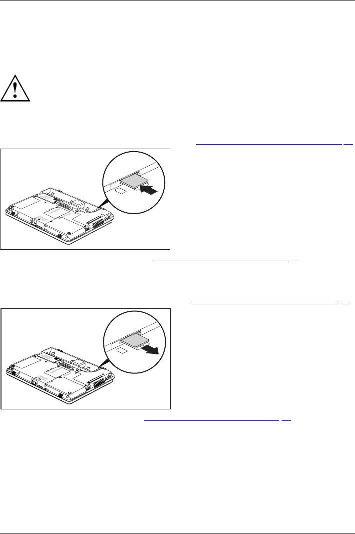
Working with the notebook
SIM card
A SIM card (Subscriber Identity Module) is a chip card which is inserted in a mobile phone or
notebook and, together with an integrated UMTS/LTE module, enables access to a mobile network.
When handling SIM cards, follow the instructions supplied by the provider.
Inserting the SIM card
►Prepare for installation of the SIM card, see chapter "Preparing to remove components", Page 83.
1
►Slide the SIM card into the slot (1)
until it is felt to engage, as shown in
the battery compartment.
►Complete the installation, see chapter "Finishing component removal", Page 89.
Removing the SIM card
►Prepare for removal of the SIM card, see chapter "Preparing to remove components", Page 83.
1
►Press on the edge of the SIM card so that
it jumps up slightly out of the slot.
►Pull the SIM card out of the slot in the
direction of the arrow (1).
►Complete the removal, see chapter "Finishing component removal", Page 89.
Fujitsu 59
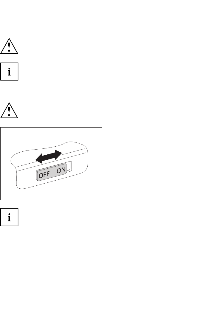
Working with the notebook
Optional Wireless LAN / Bluetooth / UMTS /
LTE wireless components
The installation of radio components not approved by Fujitsu Technology Solutions
will invalidate the certifications issued for this device.
Depending on the device configuration you ordered, your device will be equipped
with Wireless LAN, Bluetooth and/or UMTS / LTE.
Switching the wireless components on and off
Before switching on your device for the first time, the on/off switch for
radio components must be in the "ON" position.
►Slide the ON/OFF switch into the "ON"
position to activate the radio components.
WirelessLA NWirelessLANBluetoothBlueto oth
or
►Slide the ON/OFF switch to the
"OFF" position to deactivate the
radio components.
If you switch off the radio components, the wireless LAN antenna and, when present,
the Bluetooth module and UMTS/LTE module will be switched off.
You can use the PlugfreeNetwork program to switch the installed radio
components on and off individually.
You can also deactivate the wireless components individually in the BIOS Setup.
For this to occur, you must either not have assigned a supervisor password or if a
supervisor password has been assigned, you must know this password.
Pay attention to the additional safety notes for devices with radio components
provided in the "Safety/Regulations" manual.
Details on using Wireless LAN can be found in the online help system
included in the Wireless LAN software.
You can find more information on how to use Bluetooth on the CD you
received with your Bluetooth software.
You can obtain more information on UMTS/LTE from your service provider.
60 Fujitsu
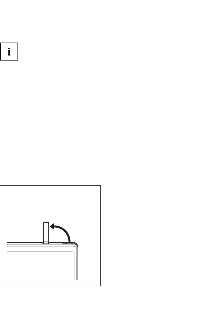
Working with the notebook
Setting up WLAN access
• Requirement: A WLAN must be available and you must have the
corresponding access information.
Information on configuring the WLAN access can be found in the
documentation for your operating system.
Access via UMTS / LTE
If you ordered an integrated UMTS / LTE module with your system, you can enjoy optimum
reception and maximum energy efficiency without awkward cables or antennas. The
optional UMTS / LTE module is ready for use straight away.
If you did not order a UMTS / LTE module, you can purchase the accessories for UMTS /
LTE reception from your retailer or your Fujitsu Technology Solutions dealer.
You will find information on establishing the connection with the UMTS / LTE network
in the documentation for the hardware used.
Your device can connect to the Internet via UMTS / LTE. To do this, use one
of the following types of connection:
• Integrated UMTS / LTE module (availability dependent on your model variant)
• a USB dongle (a USB stick with your mobile phone provider’s SIM card)
• a mobile end-device (e.g. mobile phone with Bluetooth or cable connection)
• UMTS ExpressCard (fits into the ExpressCard slot on your device)
UMTS/LTE antenna
1
►To improve the signal strength of the
UMTS/LTE, fold out the UMTS/LTE antenna
in the direction of the arrow (1).
UMTSUM TS
Fujitsu 61
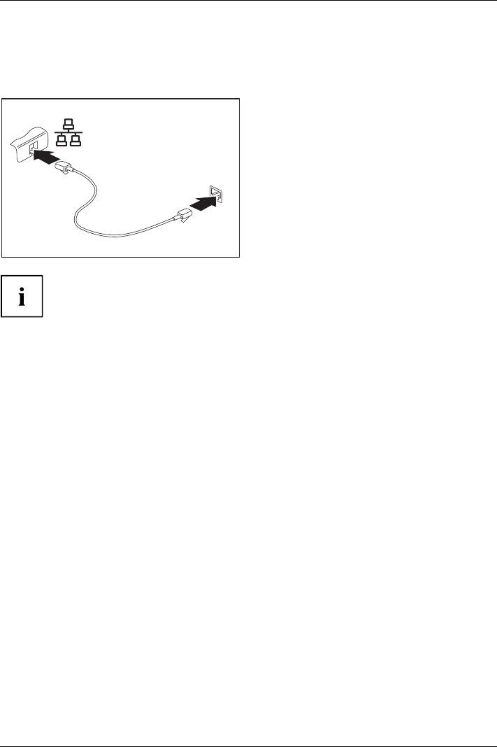
Working with the notebook
Ethernet and LAN
EthernetLAN
The internal network module of your notebook supports Ethernet LAN. You can use it to
establish a connection to a local network (LAN = Local Area Network).
2
1
►Connect the network cable to the LAN
port of the notebook (1).
►Connect the network cable to your
network connection (2).
Your network administrator can help you to configure and use the LAN connections.
The network cable is not included in the delivery scope. This type of
cable can be obtained from a specialist dealer.
Your Port Replicator (optional)
Your Port Replicator is a device that enables you to quickly connect your notebook
to your peripherals, such as a monitor, printer etc.
The features offered by the Port Replicator include standard ports for
monitor, audio, mouse and keyboard.
You need only dock the notebook in order to use your peripheral devices.
62 Fujitsu
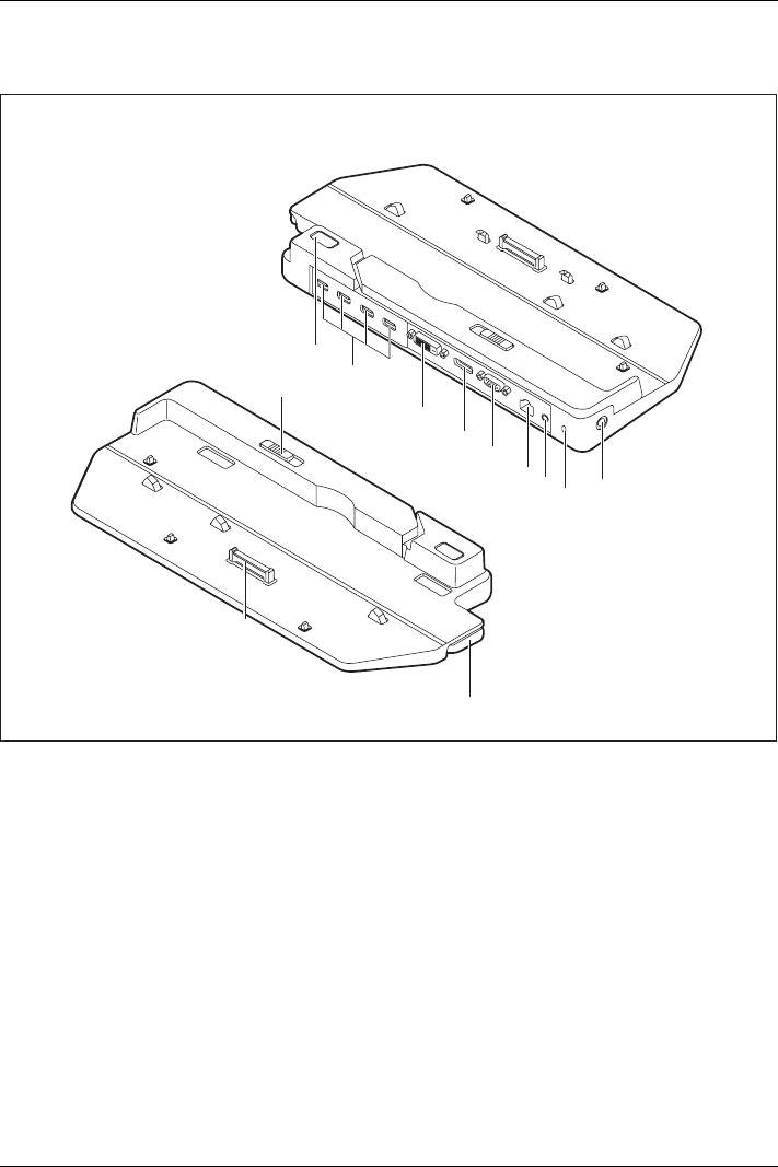
Working with the notebook
Ports on the Port Replicator
PortReplicatorPorts
1
12
2
3
4
5
678
10
11
9
1 = ON/OFF switch
2 = USB ports (USB 3.0)
3=DVIport
4 = DisplayPort
5 = VGA monitor port
6 = LAN port
7 = Headphone port
8 = Security Lock device
9 = DC input connector (DC IN)
10 = Adjusting lever of the Port Replicator
11 = Unlocking lever
12 = Connector on the Port Replicator for the
docking port on the bottom of the notebook
Fujitsu 63

Working with the notebook
Setting up the port replicator
Select a suitable location for the port replicator before setting it up.
Follow the instructions below when doing so:
• Never place the port replicator on a soft surface (e.g. carpeting, upholstered furniture, bed).
This can block the air vents of the notebook and cause overheating and damage.
• Place the port replicator on a stable, flat and non-slip surface. Please note that the
port replicator’s rubber feet may mark certain types of surface.
• Never place the port replicator and the mains adapter on a heat-sensitive surface.
• Do not expose the port replicator to extreme environmental conditions.
Protect the port replicator from dust, humidity and heat.
Connect the notebook to the port replicator
The Port Replicator supports various LIFEBOOK models. The adjusting
lever of the Port Replicator can be used to adapt the Port Replicator
to the size of the particular LIFEBOOK.
Before connecting the notebook to the port replicator, check if the setting
lever of the port replicator is in the right position. If necessary, adjust
the setting lever to the correct position.
►Disconnect the mains adapter cable from the DC socket (DC IN) of the notebook.
64 Fujitsu
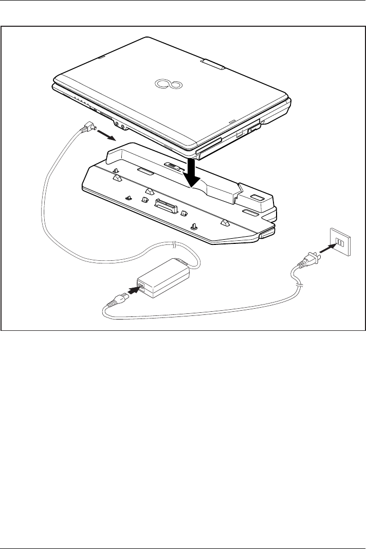
Working with the notebook
1
2
3
►Position the notebook on the port replicator in such a way that the docking connector on the
underside of the notebook is aligned with the docking connector of the port replicator as shown.
►Press down on the notebook’s rear corners so that it locks into position.
►Connect the mains adapter cable to the DC jack (DC IN) of the port replicator (1).
►Connect the power cable to the mains adapter (2).
►Plug the power cable into the mains socket (3).
Fujitsu 65
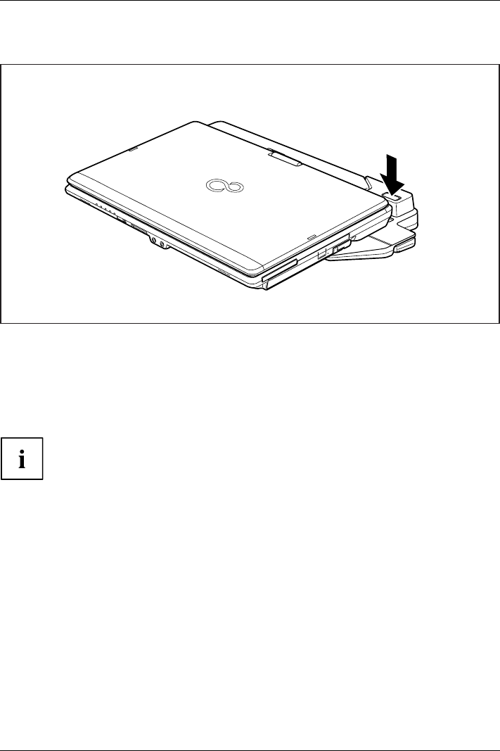
Working with the notebook
Switching on the notebook via the port replicator
►Press the ON/OFF switch on the port replicator to switch the notebook on.
Switching off notebook via Port Replicator
►Close all applications and shut down your operating system (please refer
to the manual for the operating system).
If the notebook cannot be shut down properly, press the ON/OFF button
on the Port Replicator for approx. four seconds. The notebook will switch
off. Any unsaved data may however be lost.
66 Fujitsu
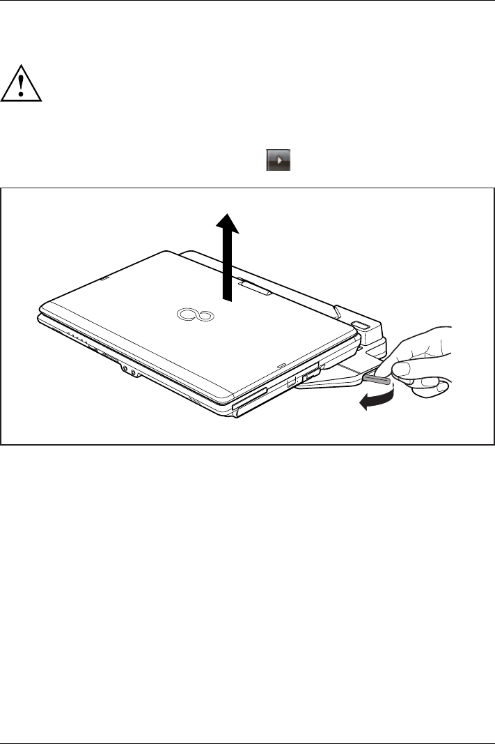
Working with the notebook
Disconnecting the notebook from the port replicator
Problems may occur if the notebook is removed from the port replicator
during operation. We recommend that you switch off the notebook beforehand
or use the Windows function Start – Undock.
Windows 7
Problems may occur if the notebook is removed from the port replicator during
operation. We recommend that you switch off the notebook beforehand or use
the Windows function Start (arrow icon) – Undock.
1
2
►Pull the release button in the direction of the arrow (1).
►Pick up the notebook (2).
Fujitsu 67

Security functions
Security functions
Securityfunctions
Your notebook has several security features that you can use to secure your
system from unauthorised access.
This chapter explains how to use each function, and what the benefits are.
Please remember that in some cases, for example, forgetting your password,
you may be locked out and unable to access your data. Therefore,
please note the following information:
• Make regular backups to external data carriers such as external hard
drives, CDs, DVDs or Blu-ray Discs.
• Some security functions need you to choose passwords. Make a note
of the passwords and keep them in a safe place.
If you forget your passwords you will need to contact the our Service
Desk. Deletion or resetting of passwords is not covered by your warranty
and a charge will be made for assistance.
Brief overview of security functions
Detailed information about the security equipment of your device can be found in
the "Professional Notebook" manual, on the "Drivers & Utilities" CD/DVD or on
the Internet at "http://www.fujitsu.com/fts/support/index.html".
Security functions Type of protection Preparation
Security Lock Mechanical Fit and lock the Kensington
Lock Cable (accessory).
Fingerprint sensor (depending
on the device)
Biometric Install the supplied fingerprint
software.
BIOS password protection Password protection for BIOS
Setup, operating system and
hard disk with supervisor and
user password. The passwords
consist of a maximum of eight
alphanumeric characters.
Specify at least one supervisor
password in the BIOS Setup
and activate the password
protection for the operating
system and hard disk as
desired.
Boot from removable media Prevents unauthorised booting
of an operating system from
external media (e.g. USB stick,
USB CD-ROM drive etc.).
In the BIOS Setup, go to the
Security menu and edit the
option Boot from Removable
Media.
Owner Information Overlay service desk or owner
information during the boot
process.
In the BIOS Setup, go to the
Security menu and edit the
option Owner Information.
Trusted Platform Module
(device dependent)
Identification and authentication
of the notebook
Define a supervisor password
in the BIOS Setup and enable
the TPM (Security Chip).
68 Fujitsu
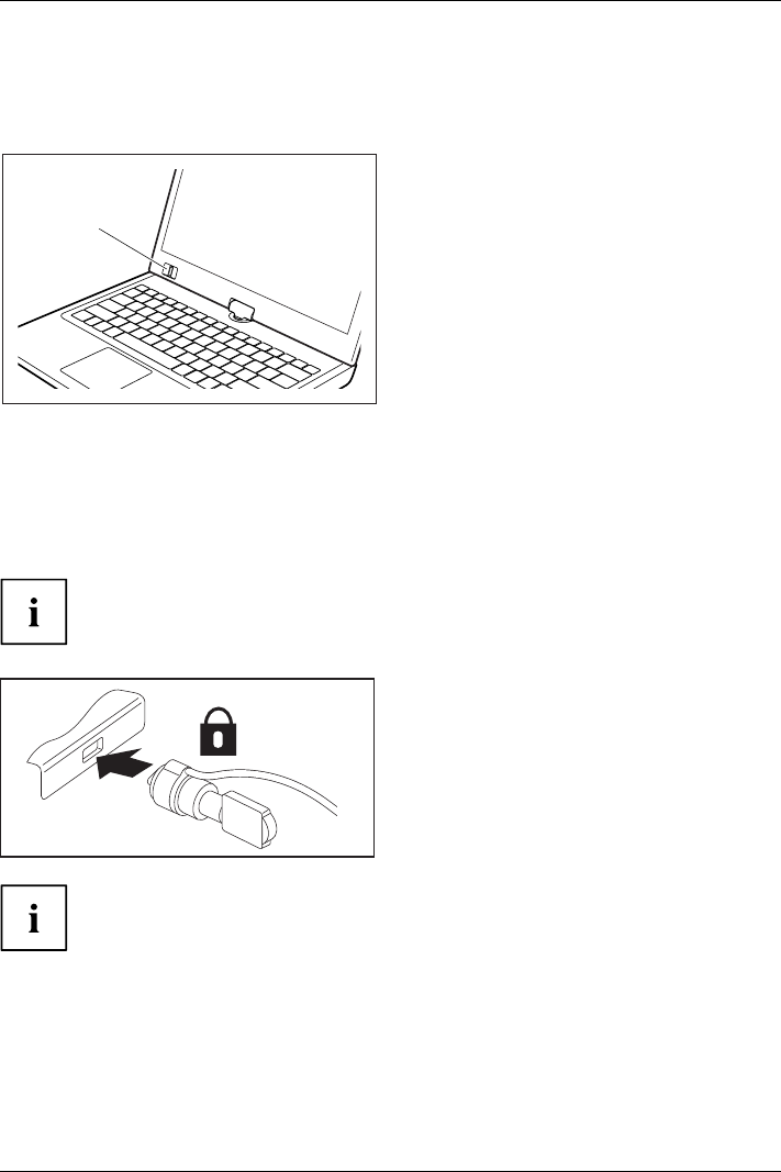
Security functions
Configuring the fingerprint sensor
Fingerprintsens orFingerprintsens or
The fingerprint sensor can record an image of a fingerprint. With additional fingerprint
software, this image can be processed and used instead of a password.
1
►You must install the fingerprint software
in order to be able to use the
fingerprint sensor (1).
Using the Security Lock
Your device comes with a Security Lock device for the Kensington Lock Cable. You can
use the Kensington Lock Cable, a sturdy steel cable, to help protect your notebook from
theft. The Kensington Lock Cable is available as an accessory.
Fujitsu Technology Solutions recommends the use of a combination lock.
►Fit the Kensington Lock Cable on the
device on your notebook.
UsingtheKensingtonLockCableSecurity LockMechan icalbackupAnti-theft protection
Attach another Kensington Lock Cable to your Port Replicator to protect
your Port Replicator from theft as well.
Fujitsu 69
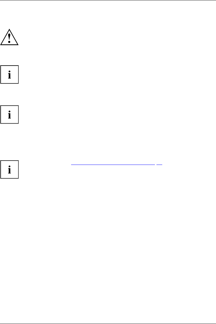
Security functions
Configuring password protection in BIOS Setup Utility
Before using the various options for password protection in the BIOS Setup utility
to increase data security, please observe the following:
Make a note of the passwords and keep them in a safe place. If you forget your
supervisor password you will not be able to access your notebook. Passwords are
not covered by your warranty and a charge will be made for assistance.
Password protectio n
Your password can be up to eight characters long and contain letters and numbers.
No distinction is made between uppercase and lowercase.
Protecting BIOS Setup Utility (supervisor and user password)
If you have opened these operating instructions on the screen, we recommend that
you print out the following instructions. Because you cannot call the instructions
onto the screen while you are setting up the password.
BIOSSetupUtility
You prevent unauthorised use of the BIOS Setup Utility with both the supervisor and the user
password. The supervisor password gives you access to all functions of the BIOS Setup
Utility, while the user password only provides some of the functions. You can only set a
user password if a supervisor password has already been assigned.
Please refer to the ""Settings in BIOS Setup Utility", Page 90 section for a
description of how to call up and operate the BIOS Setup Utility.
Setting supervisor and user password
►Start the BIOS Setup Utility and go to the Security menu.
►Select the Set Supervisor Password field and press the Enter key.
With Enter new Password: you are asked to enter a password.
►Enter the password and press the Enter key.
Confirm new Password requires you to confirm the password.
►Enter the password again and press the Enter key.
Changes have been saved is a confirmation that the new password has been saved.
►To set the user password, select Set User Password and proceed exactly as
when configuring the supervisor password.
If you do not want to change any other settings, you can exit BIOS Setup Utility.
►In the Exit menu, select the option Save Changes & Exit.
►Select Yes and press the Enter key.
PasswordSupervisorpasswordUserpassword
The notebook will be rebooted and the new password will come into effect. It will now be
necessary to first enter your supervisor or user password in order to open the BIOS Setup Utility.
Please note that the user password only provides access to a few of the BIOS settings.
70 Fujitsu

Security functions
Changing the supervisor or user password
You can only change the supervisor password when you have logged into the
BIOS Setup Utility with the supervisor password.
PasswordSupervisorpasswordUserpassword
►Call the BIOS Setup Utility and go to the Security menu.
►When changing the password, proceed exactly as for password assignment.
Removing passwords
To remove a password (without setting a new password) perform the following steps:
PasswordSupervisorpasswordUserpassword
►Start the BIOS Setup Utility and go to the Security menu.
►Highlight the Set Supervisor Password or Set User Password field and press the Enter key.
You will be requested to enter the current password by the Enter Current Password prompt.
You will be requested to enter a new password by the Enter New Password prompt.
►Press the Enter key twice.
►In the Exit menu, select the option Save Changes & Exit.
►Select Yes and press the Enter key.
The notebook will now reboot with the password removed.
Removing the supervisor password simultaneously deactivates the user password.
Password protection for booting of the operating system
With the supervisor password you have set in the BIOS Setup Utility (see
section "Setting supervisor and user password", Page 70), you can also
prevent booting of the operating system.
Operating system
Activating system protection
►Start the BIOS Setup Utility and go to the Security menu.
Operatingsystem
►Select the PasswordonBootoption and press the Enter key.
►Select the desired option (Disabled,First Boot or Every Boot) and press the Enter key
►Select the Save Changes & Exit option under Exit.
The notebook will reboot. You will be prompted to enter your password (the supervisor password).
Deactivating system protection
►Start the BIOS Setup Utility and go to the Security menu.
Operatingsystem
►Select the PasswordonBootoption and press the Enter key.
►Select the Disabled option and press the Enter key.
If you do not want to change any other settings, you can exit BIOS Setup Utility.
►Select the Save Changes & Exit option under Exit.
The notebook will reboot. The system is no longer password-protected.
Fujitsu 71

Security functions
Password protection for the hard disk
Passwordprotect ion:
The had disk password prevents unauthorised access to the hard disk drives
and is checked internally each time the system is booted. The condition for this
is that you have assigned at least the supervisor password.
Activating hard disk protection
►Call up the BIOS Setup and select the Security menu.
If you have not assigned BIOS passwords yet, define the supervisor and the user
password now, if desired (see "Security functions", Page 68).
►Mark the Hard Disk Security field and press the Enter key.
►In the Drive0 area mark the Set Master Password field and press the Enter key.
Enter new Password then appears and you are asked to enter a password.
►Enter the password and press the Enter key.
Confirm new Password requires you to confirm the password.
►Enter the password again and press the Enter key.
Setup Notice: Changes have been saved is displayed to confirm that the
new password has been saved.
►To assign the password for the second hard disk (Drive1), go to the Drive1 area and
select the field Set Master Password, then proceed in exactly the same way as for
setting up the password for the first hard disk (Drive0).
The field Password Entry on Boot is set to Enabled by default. You can exit the BIOS
Setup once you have finished changing the settings.
►From the Exit menu, choose the option Exit Saving Changes.
►Press the Enter key and select Ye s.
The notebook reboots and your hard disk is now protected with a password. The system
will ask you to enter the password when the notebook is restarted again.
Deactivating hard disk protection
To cancel a password without setting a new one, proceed as follows:
►Call up the BIOS Setup and select the Security menu.
►Mark the Hard Disk Security field and press the Enter key.
►In the Drive0 area mark the Set Master Password field and press the Enter key.
You will be initially requested to enter the old password by the Enter current Password prompt.
You will then be requested to enter a new password by the Enter new Password prompt.
►After entering the password, press the Enter key three times.
►From the Exit menu, choose the option Exit Saving Changes.
►Press the Enter key and select Ye s.
The notebook reboots, and password protection for the hard disk is cancelled.
►To cancel the password for the second hard disk (Drive1), go to the Drive1 area
and select the field Set Master Password, then proceed in exactly the same way as
for cancelling the password for the first hard disk (Drive0).
72 Fujitsu

Security functions
Using the security function of the tablet keys
If you have allotted a supervisor and/or user password in the form of tablet key combinations as
described below, you can use the tablet keys to enter this when you start your device.
Setting the Supervisor password
►Select Start - Run.
►Enter the following at the command line: C:\Program Files\Fujitsu\Security
Panel Application\Supervisor\FJSECS.EXE.
►Confirm with Enter .
►Follow the instructions on the screen.
Setting the User password
►Select Start - All Programs.
►Select Security Panel Application – Security Panel Application.
►Follow the instructions on the screen.
Entering passwords using the tablet buttons
The passwords to be entered via the tablet buttons are usually composed of a combination of
button presses, e.g. button 2+ button 3followed by button 1and the ENT button.
►Enter your password using the buttons 1to 4.
►Confirm by pressing ENT .
The device will be unlocked.
Fujitsu 73

Security functions
Trusted Platform Module (TPM) (device-dependent)
TPMTrustedPlatfor m Module
To use the TPM, you must activate the TPM in the BIOS Setup before the software
is installed. The condition for this is that you have assigned at least the supervisor
password (see "Security functions", Page 68).
Enabling TPM
• Requirement: You have assigned a supervisor password, see "Security functions", Page 68.
►Call up the BIOS Setup and select the Security menu.
►Mark the TPM Security Chip Setting field and press the Enter key.
►Select Enabled to activate the TPM.
Once you have activated the TPM the Clear Security Chip option appears.
Select Clear Security Chip to delete the holder in the TPM. By clicking on Enabled,
all secret keys (e.g. SRK - Storage Root Keys, AIK - Attestation Identity Keys
etc.) generated by applications are deleted.
Please note that you will then no longer be able to access the data you have
encrypted with the keys based on that holder.
►Select the Exit Saving Changes option in the Exit menu.
►Press the Enter key and select Ye s.
The notebook will restart, and TPM will be enabled after the reboot.
Disabling TPM
• Requirement: You have assigned a supervisor password, see "Security functions", Page 68.
►Call up the BIOS Setup and select the Security menu.
►Mark the TPM Security Chip Setting field and press the Enter key.
►Select Disabled to deactivate the TPM.
►From the Exit menu, choose the option Exit Saving Changes.
►Press the Enter key and select Ye s.
Your notebook will now restart and TPM will be disabled.
74 Fujitsu

Connecting external devices
Connecting external devices
Always refer to the safety information provided in "Important notes", Page 12 before
connecting or disconnecting any devices to or from your notebook.
Always read the documentation supplied with the device you wish to connect.
Never connect or disconnect cables during a thunderstorm.
Never pull at a cable when disconnecting it. Always grasp the plug.
Follow the steps below in order, when connecting or disconnecting
devices to your notebook:
With some devices such as USB devices, it is not necessary to switch off
the notebook and the device before connecting/disconnecting. For more
information about whether or not devices need to be switched off, please refer
to the documentation supplied with the external device.
Some of the external devices require special drivers (see the operating
system and external device documentation).
Connecting devices to the notebook
1. Turn off your notebook and all external devices.
2. Unplug your notebook and all devices from the mains sockets.
3. Connect the cables for your external devices following the instructions.
4. Plug all power cables into the mains sockets.
DevicesPeripher aldevices
Disconnecting devices from the notebook
1. Turn off your notebook and all external devices.
2. Unplug your notebook and all devices from the mains sockets.
3. Disconnect the cables for your external devices following the instructions.
DevicesPeripher aldevices
Fujitsu 75
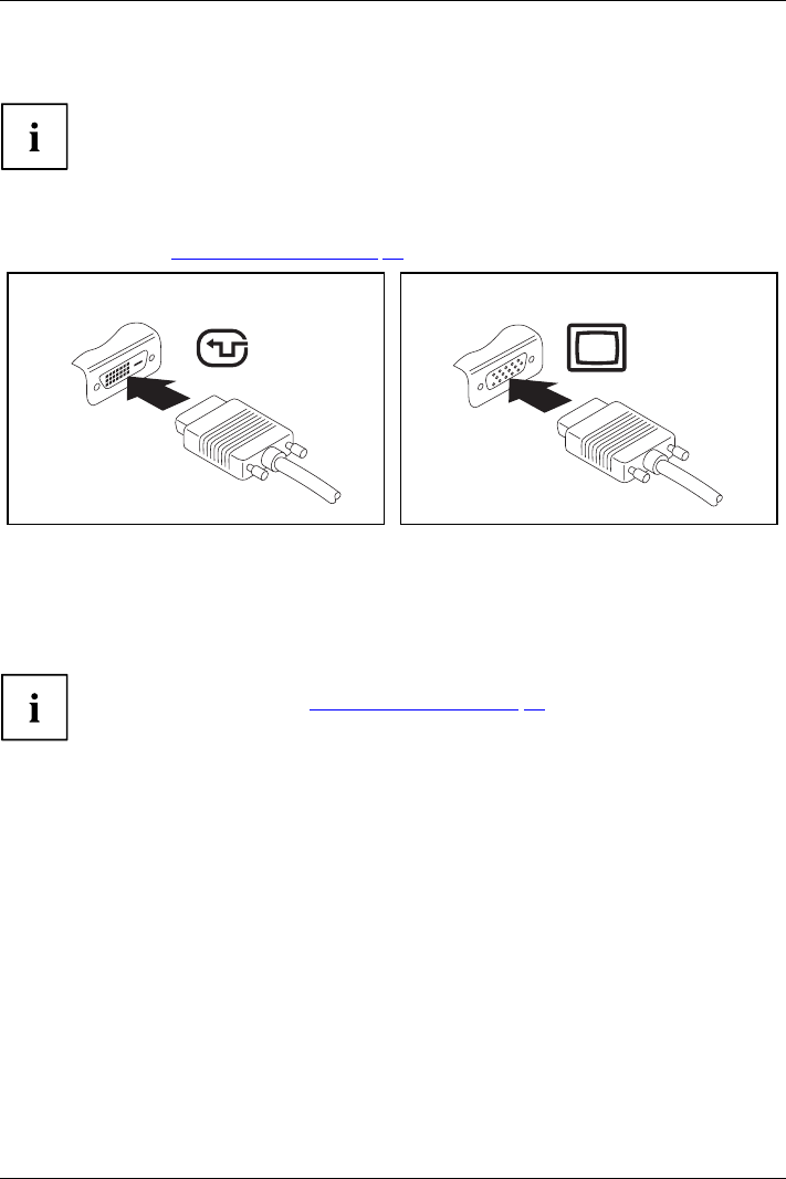
Connecting external devices
Connecting an external monitor
The Port Replicator, available as an option for your notebook, offers
you a DVI port and a DisplayPort.
An analogue monitor is connected to the analogue VGA monitor port, a digital monitor to the
DVI-I monitor port of the port replicator. Screen output is limited to a maximum of two screens
at any one time (see "Key combinations", Page 40, section "Toggle output screen").
MonitorVGAcon nection socketScreenportMonitorport
Digital DVI monitor port Analogue VGA monitor port
►Switch off the notebook and the external monitor.
►Plug the data cable of the external monitor into the monitor port.
►First switch on the external monitor and then the notebook.
You can also switch back and forth between the external monitor and the notebook’s
LCD monitor, see chapter "Key combinations", Page 40.
You can display the same picture on the external monitor and the
notebook LCD screen simultaneously.
76 Fujitsu
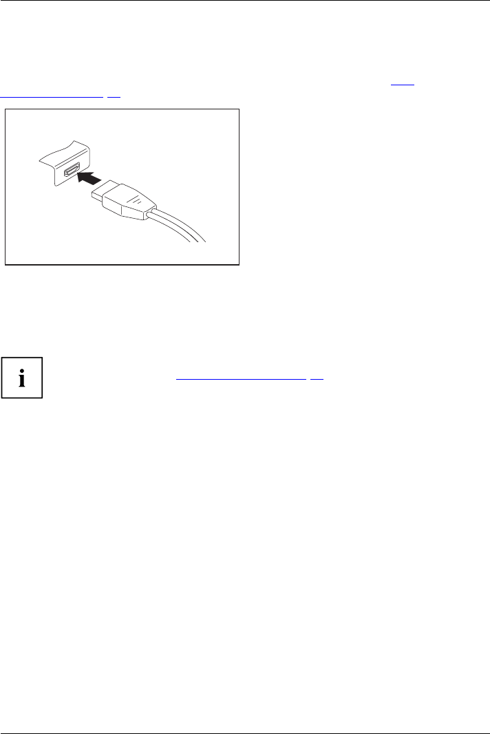
Connecting external devices
Connecting an external monitor to the DisplayPort
It is possible to connect a digital monitor to the DisplayPort on the port replicator.
Screen output is limited to a maximum of two screens at any one time (see "Key
combinations", Page 40, section "Toggle output screen").
Digital DisplayPort
►Switch off the notebook and the external monitor.
►Plug the data cable of the external monitor into the monitor port.
►First switch on the external monitor and then the notebook.
You can also switch between the external monitor and the LCD monitor of the
notebook, see chapter "Key combinations", Page 40.
You can display the same picture on the external monitor and the
notebook LCD monitor simultaneously.
Fujitsu 77
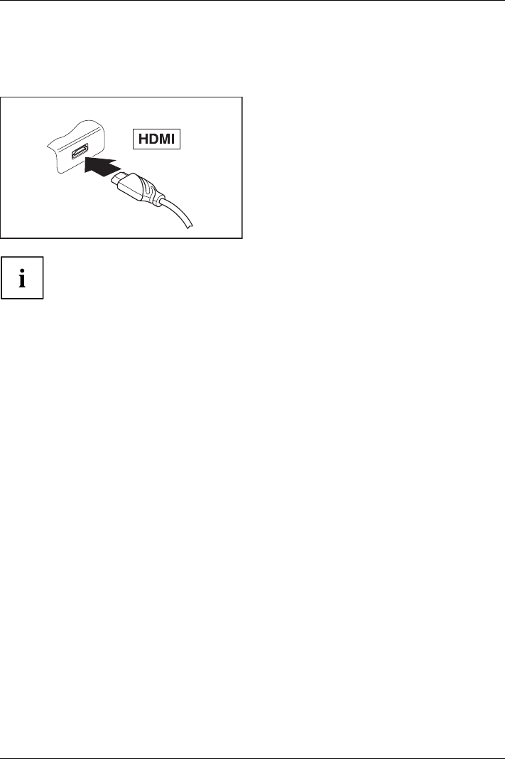
Connecting external devices
HDMI port
HDMIport
The HDMI port on your notebook can be used to connect an external amplifier,
LCD TV or a plasma TV with an HDMI connection.
►Connect the data cable to the
external device.
►Connect the data cable to the HDMI
port of the notebook.
Some LCD televisions have only two loudspeaker connections and therefore
cannot reproduce Dolby digital or DTS. In order to reproduce the sound, you
must go into Windows and adjust the sound settings.
Proceed as follows:
►Select Startsymbol – (Settings) – Control Panel – Hardware and Sound – Sound.
►Mark Realtek HDMI Output.
►Select Properties – Supported formats.
►Deactivate the settings DTS audio and Dolby digital.
►Confirm the settings with OK.
78 Fujitsu
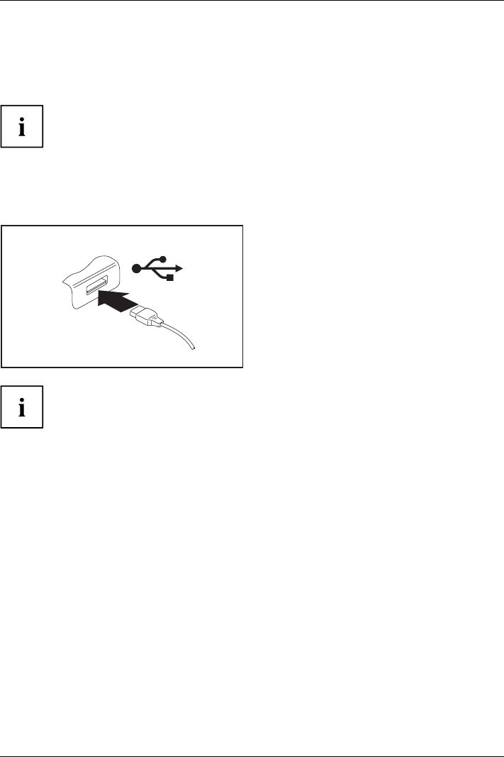
Connecting external devices
Connecting USB devices
USBports
On the USB ports, you can connect external devices that also have a USB port
(e.g. a DVD drive, a printer, a scanner or a modem).
USB devices are hot-pluggable. This means you can connect and disconnect
devices while your operating system is running.
USB 1.x has a maximum data transfer rate of 12 Mbit/s.
USB 2.0 has a data transfer rate of up to 480 Mbit/s.
USB 3.0 has a data transfer rate of up to 5 Gbit/s.
Additional information can be found in the documentation for the USB devices.
►Connect the data cable to the
external device.
►Connect the data cable to a USB
port of the notebook.
Device drivers
USB devices will be automatically recognised and installed by your operating system.
Fujitsu 79
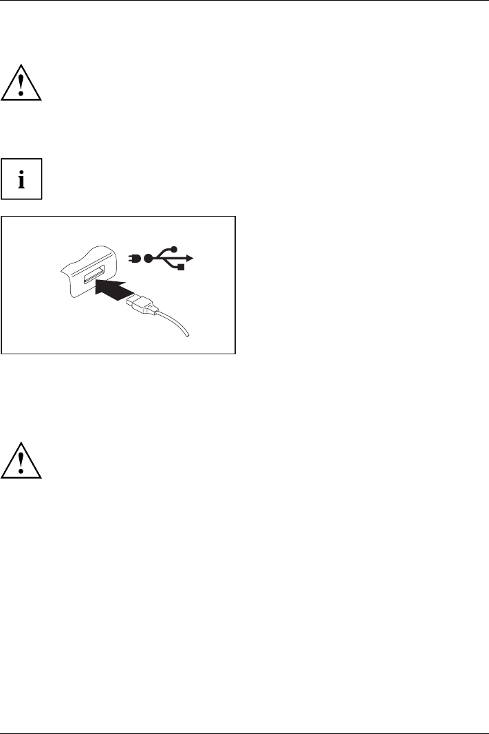
Connecting external devices
USB port with charging function (Anytime USB charge)
USBchargingfunction
It is recommended that the notebook be operated with the power supply connected
whenever the USB port with charging function is in use, as this function will drain
the battery more quickly if an external USB device is being charged.
The power supply unit must already be connected when the notebook is
switched off, as otherwise the USB charging function will be disabled and
the connected USB devices will not be charged.
Some USB devices (e.g. mobile telephones) require a driver in order to utilise the
USB charging function. In this case the USB charging function will not work when the
notebook is switched off, as no drivers are active when the notebook is switched off.
You can use this USB port to charge or supply power to a USB device (e.g. to charge a PDA
or a mobile phone or to connect a USB lamp), even if the notebook is switched off.
How to remove USB devices correctly
Always correctly remove the device according to the rules described below,
to ensure that none of your data is lost.
►Left click on the icon to safely remove hardware, located in the taskbar.
►Select the device which you want to shut down and remove.
►Press the Enter key.
Wait for the dialogue box which tells you that it is now safe to remove the device.
80 Fujitsu
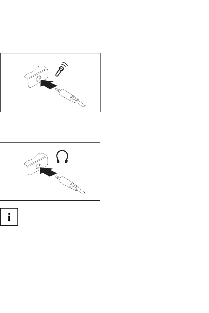
Connecting external devices
Connecting external audio devices
Microphone port/Line In
Audiodevices, connectingAudioportsMicrophone ,connecting
The microphone port/Line In allows you to connect an external microphone, a MiniDisc
player, MP3 player, CD player or a tape deck to your notebook.
►Connect the audio cable to the
external device.
►Connect the audio cable to the microphone
port/Line In of the notebook.
Headphone port
Connectingaudio dev ices
AudioportsConnectin gheadphones
You can connect headphones or external loudspeakers to your notebook via the headphone port.
►Connect the audio cable to the
external device.
►Connect the audio cable to the headphone
port of the notebook.
The internal loudspeakers are disabled.
If you purchase a cable from a retailer, please note the following information:
The headphone port on your notebook is a "3.5 mm jack socket".
If you want to connect headphones or a speaker you will need a "3.5 mm jack plug".
Fujitsu 81
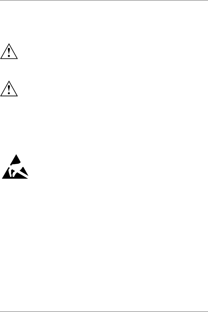
Removing and installing components during servicing
Removing and installing components
during servicing
Only qualified technicians should repair your notebook. Unauthorised
opening or incorrect repair may greatly endanger the user (electric shock,
fire risk) and will invalidate your warranty.
Components
Serv icing
After consulting the Hotline/Service Desk, you may remove and install the
components described in this chapter yourself.
If you remove and install components without consulting the Hotline/Service
Desk, then the warranty of your notebook will be voided.
Notes on installing and removing boards
and components
• Switch the notebook off and pull the power plug out of the mains socket.
• Always remove the battery.
• Take care when you use the locking mechanisms on the battery and any other component.
• Never use sharp objects such as screwdrivers, scissors or knives as leverage to remove covers.
NotesBoardESD
Boards with electrostatic sensitive devices (ESD) are marked with the label
shown.
When handling boards fitted with ESDs, you must always observe the following
points:
• You must always discharge static build up (e.g. by touching a grounded
object) before working.
• The equipment and tools you use must be free of static charges.
• Remove the power plug from the mains supply before inserting or removing
boards containing ESDs.
• Always hold boards with ESDs by their edges.
• Never touch pins or conductors on boards fitted with ESDs.
82 Fujitsu
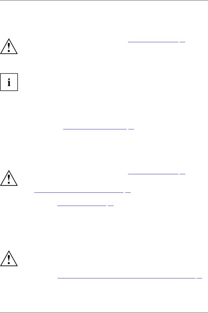
Removing and installing components during servicing
Preparing to remove components
If you are going to remove or change system components, prepare for the removal as follows:
Please observe the safety information in chapter "Important notes", Page 12.
Remove the power plug from the mains outlet !
►Switch the device off.
The device must not be in energy-saving mode !
►Close the LCD screen.
►Remove all the cables from the device.
►Turn the device over and place it on a stable, flat and clean surface. If necessary, lay an
anti-slip cloth on this surface to prevent the device from being scratched.
►Remove the battery (see "Removing the battery", Page 46).
Installing and removing memory expansion
MemorymoduleMainmemoryRemovingmemory
Systemexpansi on
Systemexpansi on
If you are asked by the Hotline/Service Desk to remove and install the memory
expansion yourself, proceed as follows:
Please observe the safety information in chapter "Important notes", Page 12.
When installing/removing memory modules, the battery must be removed from
the notebook and the notebook must not be connected to the power supply,
see "Preparing to remove components", Page 83.
Only use memory expansion modules that have been approved for your
notebook (see "Technical data", Page 99).
Never use force when installing or removing a memory extension.
Make sure that foreign objects do not fall into the memory extension compartment.
You must open the service compartment to remove or install a memory module. On some devices,
opening the compartment may expose other components. These components should be removed
and replaced only by authorised specialists. Therefore, be sure to observe the following:
Individual components can become very hot during operation. Therefore, we
recommend that you wait one hour after switching off the notebook before removing
or installing memory modules. Otherwise, there is a risk of suffering burns!
As some components are exposed that are sensitive to static electricity, please take
note of chapter "Notes on installing and removing boards and components", Page 82.
Fujitsu 83
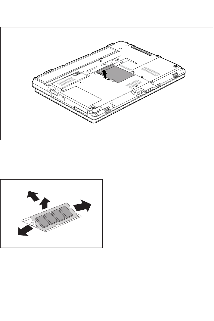
Removing and installing components during servicing
Removing a cover
2
1
►Remove the screw (1).
►Pull off the cover from the notebook in the direction of the arrow (2).
Removing memory modules
3
2
1
1
►Carefully push the two mounting
clips outwards (1).
MemoryexpansionMemorymodule
The memory module snaps upwards (2).
►Pull the memory module out of its slot
in the direction of the arrow (3).
84 Fujitsu
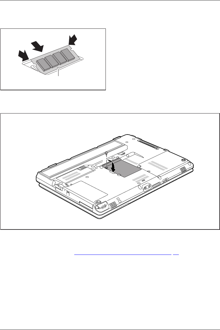
Removing and installing components during servicing
Installing a memory module
2
a
1
2
►Insert the memory module with the contacts
and the recess (a) facing the slot (1).
MemoryexpansionMemorymodule
►Carefully push the memory module
downwards until you feel it click
into place (2).
Attaching the cover
1
2
►Place the cover into position, following the direction of the arrow (1).
►Fasten the cover with the screw (2).
►Install the battery again (see "Removing and installing the battery", Page 46).
►Turn the notebook the right way up again and place it on a flat surface.
►Reconnect the cables that were previously disconnected.
Fujitsu 85
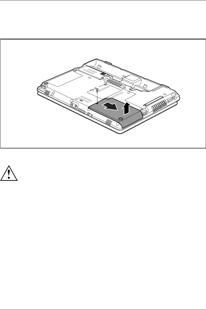
Removing and installing components during servicing
Removing and installing the harddisk
Removing a cover
1
3
2
►Remove the screw (1).
Keep the screw in a safe place. If you are removing more than one component at
the same time, store the screws for the individual components separate from each
other. If you install the wrong screws, components may be damaged.
►Slide the cover in direction of the arrow (2).
►Lift the cover off the notebook (3).
86 Fujitsu

Removing and installing components during servicing
Removing a hard disk
2
1
►To release the hard disk from the contacts, pull it in the direction of the arrow (1).
►Remove the hard disk from the hard disk compartment (2).
Fujitsu 87
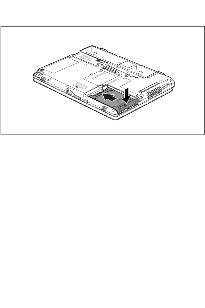
Removing and installing components during servicing
Installing a hard disk
1
2
►Place the hard disk into the hard disk compartment (1).
►Push the hard disk in the direction of the arrow (2) until the contacts of the hard disk engage.
88 Fujitsu
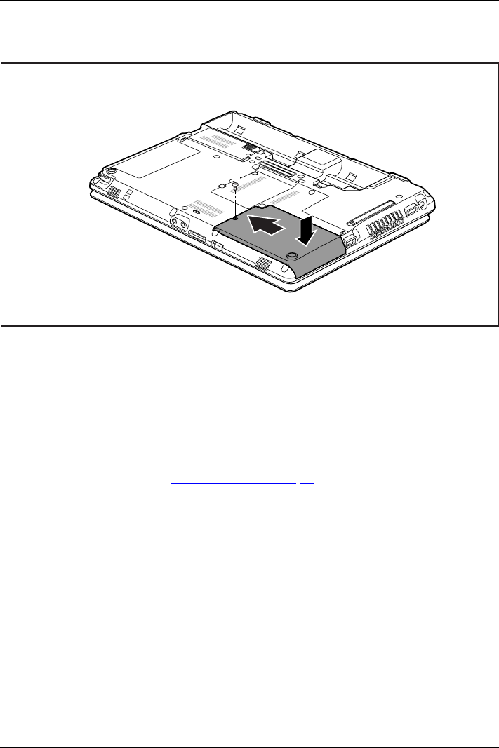
Removing and installing components during servicing
Attaching the cover
3
1
2
►Place the cover in the correct mounting position (1).
►Slide the cover in the direction of the arrow (2).
►Tighten the screw (3).
Finishing component removal
After you have removed or changed the system components as you required, please
prepare your device for operation again as follows:
►Install the battery again (see "Inserting battery", Page 47).
►Turn the notebook the right way up again and place it on a flat surface.
►Reconnect the cables that you disconnected before.
Fujitsu 89
Settings in BIOS Setup Utility
Settings in BIOS Setup Utility
BIOSSetupUtilitySystemsettings,BIOSSetup UtilityConfiguration,BIOSSetupUtilitySetupSystemconfigurationHardwareconfiguration
The BIOS Setup Utility allows you to set the system functions and the hardware
configuration for the notebook.
When it is delivered, the notebook is set to factory default settings. You can
change these settings in BIOS Setup Utility. Any changes you make take effect as
soon as you save and exit the BIOS Setup Utility.
The BIOS Setup Utility program contains the following menus:
About Displays information relating to the BIOS, processor and notebook
System Advanced system settings
Advanced Configuration of various hardware components, such as mouse, keyboard,
processor
Security Password settings and security functions
Boot Configuration of the start-up sequence
Exit Exits the BIOS Setup Utility
Starting the BIOS Setup Utility
►Reboot the device (switch off/on or reboot the operating system).
BIOSSetupUtility
The following or a similar display appears on the screen at start-up:
<F2> BIOS Setup <F12> Boot Menu
►Press the function key F2 .
►If a password has been assigned, enter the password and press the Enter key.
If you have forgotten the password, contact your system administrator
or contact our customer service centre.
The BIOS Setup Utility starts.
Operating BIOS Setup Utility
BIOSSetupUtility
Press the F1 key to display help on the operation of the BIOS Setup Utility. The description
of the individual settings is shown in the right-hand window of the BIOS Setup Utility.
With the F9 key you can load the default settings of the BIOS Setup Utility.
►Use the cursor keys ←or →to select the menu you wish to access to make changes.
The menu is displayed on the screen.
►Select the option you want to change with the cursor keys ↑or ↓.
►Press the Enter key.
►Press the ESC key to exit the selected menu.
►For future reference, make a note of the changes you have made (for example, in this manual).
90 Fujitsu

Settings in BIOS Setup Utility
Exiting BIOS Setup Utility
BIOSSetupUtility
You need to select the desired option in the Exit menu and activate it by pressing the Enter key:
Exit Saving Changes - save changes and exit BIOS Setup Utility
►To save the current menu settings and exit the BIOS Setup Utility,selectExit Saving Changes and Yes .
The notebook is rebooted and the new settings come into effect.
Exit Discarding Changes – Discard changes and
exit BIOS Setup Utility
►To discard the changes, select Exit Discarding Changes and Yes .
The settings in place when BIOS Setup Utility was called remain effective. BIOS
Setup Utility is terminated and the notebook is rebooted.
Load Setup Defaults – Copy Standard Entries
►To copy the standard entries for all menus of the BIOS Setup Utility,
choose Load Setup Defaults and Ye s.
Discard Changes – Discard changes without exiting
the BIOS Setup Utility
►To discard the changes you have made, select Discard Changes and Ye s.
ThesettingsinplacewhenBIOS Setup Utility was called remain effective.
You can now make additional settings in the BIOS Setup Utility.
►If you want to exitBIOS Setup Utilitywith these settings, select Exit Saving Changes and Yes.
Save Changes - save changes without exiting
the BIOS Setup Utility
►To save the changes, select Save Changes and Yes.
The changes are saved. You can now make additional settings in the BIOS Setup Utility.
►If you want to exit BIOS Setup Utility with these settings, choose Exit Saving Changes and Yes.
Save Changes and Power Off
►To save the changes and switch off your device, select Save Changes and Power Off and Yes.
The changes are saved. Your device is shut down.
Fujitsu 91

Troubleshooting and tips
Troubleshooting and tips
TroubleshootingTipsFaultTroubleshooting
If a fault occurs, try to correct it as described. If you fail to correct the problem, proceed as follows:
►Make a note of the steps and the circumstances that led to the fault. Also
make a note of any error messages displayed.
►Switch the notebook off.
►Please contact the Hotline/Service Desk.
You can contact Fujitsu Service and Support in the following ways:
• Toll free: 1-800-Fujitsu (1-800-838-5487)
• Website: "http://solutions.us.fujitsu.com/www/content/support/contact/index.php"
Please have the following information ready when you call:
• The model name and serial number of the notebook. The serial number is
located on a sticker on the underside of the notebook.
• Notes of any messages that appear on the screen and information on acoustic signals.
• Any changes you have made to the hardware or software since
receiving the notebook.
• Any changes you have made to the BIOS Setup settings since receiving the notebook.
• Your system configuration and all peripheral devices connected to your system.
• Your sales contract.
Our notebooks have been designed primarily with mobile applications in mind.
This means that considerable effort has been made to optimize components and
equipment in terms of weight, space and energy requirements. Depending on the
particular configuration you have purchased, it is possible that functionality may be
slightly reduced compared to a desktop PC if you are running processor-intensive
gaming software, e.g. games with intensive 3D graphics. Updating your hardware with
drivers which have not been approved by Fujitsu may result in performance losses,
data losses or malfunction of the equipment. A list of approved drivers and current
BIOS versions can be downloaded from: "http://solutions.us.fujitsu.com"
Help if problems occur
Should you encounter a problem with your computer that you cannot resolve yourself:
►Note the ID number of your device. The ID number is found on the type rating
plate on the back or underside of the casing.
►For further clarification of the problem, contact the Fujitsu Service Desk. When you do
this, please have ready the ID number and serial number of your system.
Recovering your Factory Image
Harddisk:Operatingsystem,recoveringFactoryImage
In the event you need to restore your original Factory Image refer to the steps
in "Appendix: Miscellaneous Information".
Fujitsu 67
Troubleshooting and tips
The notebook’s date or time is incorrect
SummertimeTime,daylightsavingsTimenotcorrectTimenotcorrectInc orre ct d at e/ti meDateisincorrectBufferbattery,load
Cause Troubleshooting
Time and date are incorrect. ►With the BIOS-Setup-Utility,you can set the
date and time in the main menu.
If the time and date are still set incorrectly after
switching on the notebook.
►Please contact your sales outlet or our
Hotline/Service Desk.
Battery indicator does not illuminate
Cause Fault elimination
The battery is not installed correctly. ►Switch the notebook off.
►Check whether the battery is installed
correctly in its compartment.
►Switch the notebook on.
The battery is fully discharged. ►Charge the battery.
or
►Install a charged battery.
or
►Connect the notebook to a mains outlet
using the mains adapter.
When certain characters are entered on the
keyboard, only numerals are written
Abeepsounds e verys eco nd
Cause Troubleshooting
The virtual numeric keypad of your device is
activated, see "Virtual numeric keypad", Page 39
►Press the Num key.
The notebook’s LCD screen remains blank
LCDscreenLCDscreenistoodark
Cause Troubleshooting
Monitor is switched off. ►Press a key or touch the touchpad.
External monitor or television set connected. ►Press the key combination to switch the
screen output, see "Key combinations",
Page 40.
Fujitsu 93
Troubleshooting and tips
The LCD screen is difficult to read
LCDscreenLCDscreen
Cause Troubleshooting
Reflected glare ►Turn the notebook or alter the tilt of the LCD
screen.
►Increase the brightness of the screen.
The external monitor remains blank
Monitor
Cause Troubleshooting
Monitor is switched off. ►Switch the external monitor on.
Power saving has been activated (monitor is
blank).
►Press any key to continue.
Brightness is set to dark. ►Adjust the brightness of the monitor.
Screen output is set to the notebook’s LCD
screen
►Press the key combinationtoswitchthe
screen output, see "Key combinations",
Page 40.
The external monitor’s power cable or data
cable is not connected properly.
►Switch off the external monitor and the
notebook.
►Check whether the power cable is plugged
properly into the external monitor and into
the power socket.
►Check whether the data cable is properly
connected to the notebook and the external
monitor (if it is plugged in with a connector).
►Switch on the external monitor and the
notebook.
The external monitor is blank or the image is unstable
ScreenMonitor
Cause Troubleshooting
The wrong external monitor has been selected
or the wrong screen resolution has been set for
the application program.
►Terminate the application program in
Windows by pressing Alt +F4 .Ifthe
fault persists after closing the program, use
the key combination for switching the screen
output (see "Key combinations", Page 40)to
switch over to the notebook’s LCD screen.
Change the following setting:
►Set the screen resolution: Set the screen
resolution as described in the documentation
foryouroperatingsystem.
►Select monitor: Select monitor 1 or 2 as
described in the documentation for your
operating system.
94 Fujitsu

Troubleshooting and tips
The cursor does not correctly follow the
pen movements
Cause Fault elimination
Pen incorrectly calibrated ►Calibrate the pen as shown under Hardware
and Sound / Tablet PC Settings in the Control
Panel, see "Setting the pen", Page 33 and
"Calibrating the pen", Page 34.
Pen input not working
Cause Troubleshooting
Incorrect driver installed. ►If your device is one which can only be
operated using the pen, install the driver for
the standard model.
or
►If your device is one which can be
operated using the pen and by finger,
install the driver for the "Dual Digitizer"
model.
The notebook cannot be started
Notebook
Cause Troubleshooting
The battery is not installed correctly. ►Check whether the battery is installed
correctly in its compartment.
►Switch the notebook on.
The battery is dead. ►Charge the battery.
or
►Insert a charged battery.
or
►Connect the mains adapter to the
notebook.
The power adapter is not connected correctly. ►Check whether the mains adapter is
connected correctly to the notebook.
►Switch the notebook on.
Fujitsu 95

Troubleshooting and tips
The notebook stops working
NotebookEnergysavingmode
Cause Troubleshooting
Notebook is in energy saving mode. ►Leave energy saving mode.
An application programme has caused the
malfunction.
►Close the application program or restart
the notebook (by restarting the operating
system or switching the device off and back
on again).
The battery is dead. ►Charge the battery.
or
►Insert a charged battery.
or
►Connect the mains adapter to the
notebook.
The printer does not print
Printerdoesnot print
Cause Troubleshooting
The printer is not switched on. ►Make sure that the printer is switched
on and ready for operation (refer to the
documentation supplied with the printer).
The printer is not connected correctly. ►Check that the data cable connecting
the notebook to the printer is properly
connected.
The printer driver is faulty or not correctly
installed, or it is the wrong printer driver.
►Check that the data cable connecting
the notebook to the printer is properly
connected.
►Check whetherthecorrectprinterdriveris
loaded (refer to the printer documentation).
The radio connection to a network does not work
Theradioconnect iont oa netwo rkdoes not wor k
Cause Troubleshooting
The wireless component is disabled. ►Switch the radio component on (see
"Switching the wireless components on and
off", Page 60).
The wireless component is enabled. Despite
this, the wireless connection to a network does
not work.
►Check whether the radio connection is
switched on via the software.
►Further information on using the radio
component can be found in the help files.
96 Fujitsu
Troubleshooting and tips
The battery discharges too quickly
Battery:
Cause Troubleshooting
The battery is either too hot or too cold. In this
case the battery indicator flashes.
►Bring the notebook up/down to a normal
temperature again.
►If the operating time of the battery life is
extremely short, the battery is probably too
old. Replace battery if necessary.
You may have an application running that
consumes a great deal of power due to frequent
accessing of the hard disk or optical drive.
►Use the mains adapter as frequently as
possible.
The maximum brightness may have been set
for the screen.
►Set the screen slightly darker with the
key combination for Decreasing the screen
brightness in order to reduce the amount of
power being drawn.
Acoustic warnings
Acousticerror m essages
Errors
Cause Troubleshooting
A beep sounds every few seconds.
The battery is almost flat.
►Charge the battery.
Error messages on the screen
Errormessagesont hes creen
Errormessage:
This section describes the error messages generated by the BIOS Setup. Error messages displayed
by the operating system or programmes are described in the relevant documentation.
If the error message appears repeatedly, despite troubleshooting measures, please
contact the place of purchase or our customer service centre.
Error message/cause Resolution
CMOS battery bad
If the error message occurs repeatedly, the
buffer battery in the notebook is flat.
►Contact your sales outlet or our customer
service centre.
System CMOS checksum bad - default configuration
used
The system configuration information is
incorrect.
►Switch the notebook off.
►Switch the notebook on.
►Press the function key F2 to access the
BIOS Setup.
►In the BIOS Setup, select the Exit menu.
►Select the entry Load Setup Defaults.
►Select OK and press the Enter key.
Fujitsu 97
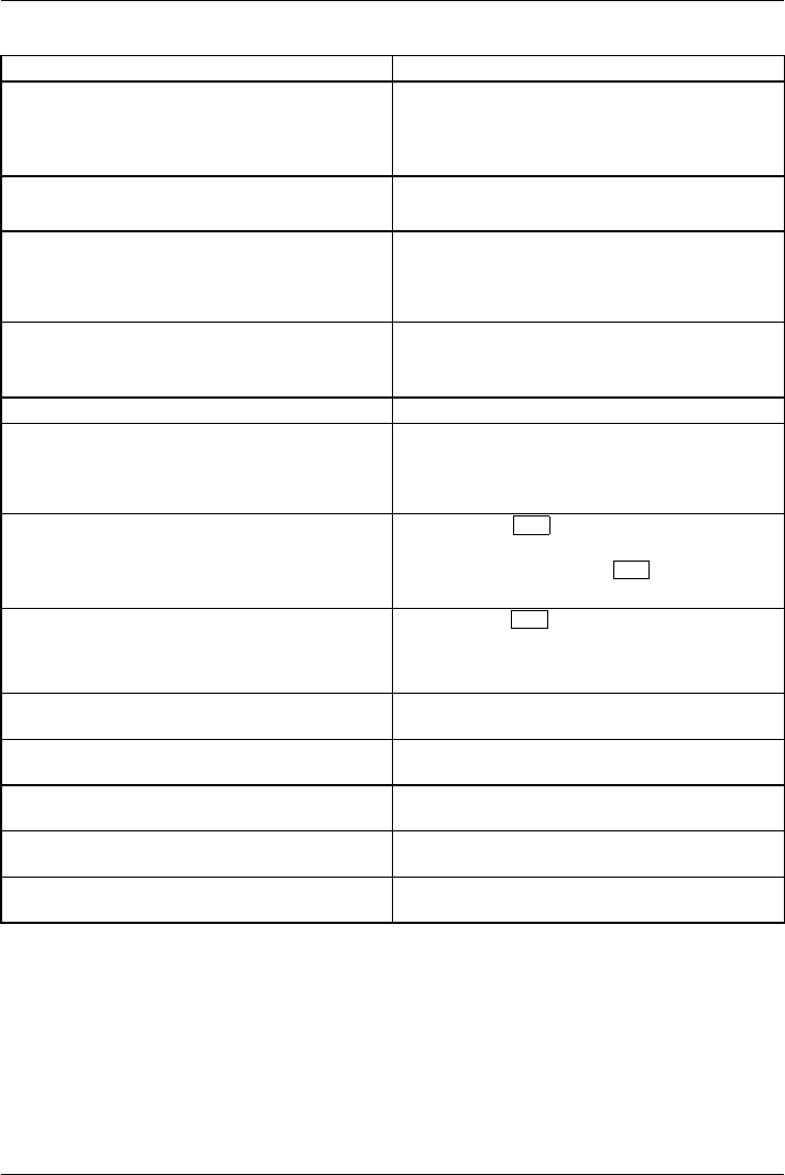
Troubleshooting and tips
Error message/cause Resolution
Extended memory failed at offset: xxxx Failing Bits:
zzzz zzzz
When testing the extended memory an error has
resulted at the address xxxx.
►Check whether the additional memory
module has been inserted correctly.
Failure Fixed Disk n
The settings of the hard disk drive are incorrect.
►Start the BIOS Setup (Primary Master
submenu) and select the correct settings.
Keyboard controller error ►Switch the notebook off with the ON/OFF
switch.
►Wait 3 - 5 seconds and switch on the
notebook again.
Keyboard error If you are using an external keyboard:
►Check the connection and reboot the
notebook.
nn Stuck key ►Make sure that no key is pressed.
Operating system not found ►Check in the BIOS Setup whether your hard
disk has been set correctly.
►Make sure that the operating system is
installed on the corresponding drive.
Press <F1> to resume, <F2> to SETUP
This error message appears if an error occurs
during the self-test before starting the operating
system.
►Press the F1 function key to start the
operating system.
►Press the function key F2 to access the
BIOS Setup.
Previous boot incomplete - Default configuration
used Due to an error during the previous system
boot, default values were used for certain
settings. Check the settings in the BIOS Setup.
►Press the F1 function key when prompted
to do so.
Real time clock error ►Contact your sales outlet or our customer
service centre.
nnnnK Shadow RAM failed at offset: xxxx Failing
Bits: zzzz
►Contact your sales outlet or our customer
service centre.
System battery is dead - Replace and run SETUP ►Contact your sales outlet or our customer
service centre.
System cache error - Cache disabled ►Contact your sales outlet or our customer
service centre.
System timer error ►Contact your sales outlet or our customer
service centre.
98 Fujitsu

Technical data
Technical data
Notebook
General
Processor 3rd Generation Intel® Core™ with vPro™
technology (vPro optional, depending on
configuration)
Main memory (SO DIMM) Maximum 16 Gbyte DDR3
2 slots for 2 Gbyte, 4 Gbyte or 8 Gbyte modules
Electrical data
Safety regulations complied with CE
Protection class II
Maximum power draw (when the notebook is
switched on and the battery is charged):
80 W (with and without connected port replicator)
LCD screen
Size 31.75 cm / 12.5" TFT HD
Resolution 1366 x 768 (HD), 16 mio. colors
Pixel class II
Brightness control 12 levels
Technology Wide-View High-Bright HD Display with LED
Background Lighting
Digitizer and glass panel • Dual Digitizer
• Matter Touchscreen
• Toughened glass
WebCam Full-HD camera (1080 p), with status indicator
Graphics card
Chip Intel® HD Graphics 4000
Maximum resolution on external display: 1920 x 1200 pixels, 16 mio. colors
on port replicator:
• VGA: 1920 x 1200 pixels
•DVI
: 1920 x 1200 pixels
• DisplayPort: 2560 x 1600 pixels
Dimensions
Width x depth x height 315.6 mm x 233 mm x 37.5-33.5 mm with rubber
feet
Weight depending on configuration from 1.8 kg
Input devices
Keyboard 85 buttons, splash-protected
Touchpad 2 keys
Tablet buttons 5 buttons + 1 Windows button
Fujitsu 99

Technical data
Pen 1 freely programmable rocker button / eraser
Slots
Memory card slot 1xSDCard
ExpressCard slot 1 x ExpressCard/54
SIM card slot 1x
Ports
Monitor port (analogue) 15-pin socket
HDMI port 1 x
LAN port Socket, RJ45
Microphone port/Line In3.5mmstereominijack
Headphones port/Line Out 3.5mmstereominijack
Docking port 100-pin socket
USB (Universal Serial Bus) Total: 3 x USB (1 x USB 3.0 with charging
function (Anytime USB charge), 2 x USB 2.0)
Security Lock 1x
Ambient conditions
Environment class DIN IEC 721 7K1
Mechanism class DIN IEC 721 7M2
Operating temperature 5℃.... 35℃
Transport temperature (2K2) –15°C .... 60°C
Port Replicator (optional)
Electrical data
Safety regulations complied with CE
Protection class II
Ports
Monitor port (analogue) 15-pin
Monitor port (digital) 25-pin, DVI-D
DisplayPort 1 x
LAN port RJ45
USB (Universal Serial Bus) 4 x USB 3.0
Audio Headphone port
Docking port 100-pin
Security Lock 1x
Ambient conditions
Environment class DIN IEC 721 7K1
Mechanism class DIN IEC 721 7M2
Operating temperature 5 °C .... 35℃
Transport temperature –15 °C .... 60 ℃
100 Fujitsu
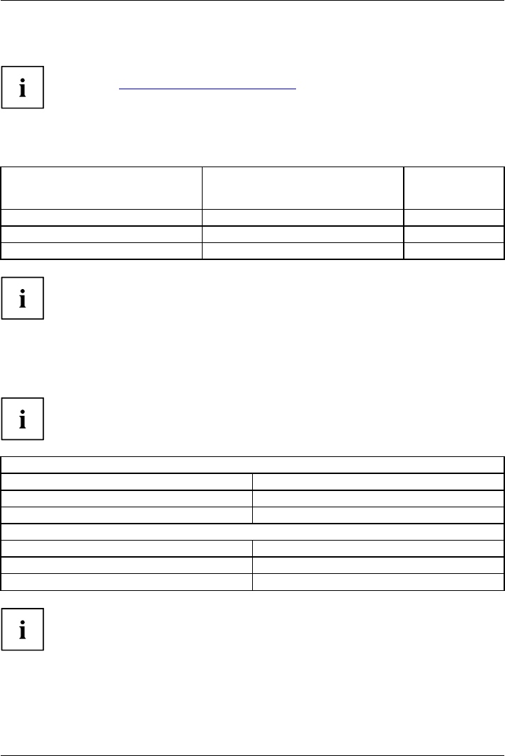
Technical data
Rechargeable battery
You will find information on the batteries used in your device on the
Internet at "http://www.fujitsu.com/fts/support/".
In addition to the main battery, you can order an optional battery which is inserted in the module slot.
All rechargeable batteries are 6-cell batteries.
Main battery
Optional battery
(to be inserted in
the module bay)
Rated voltage 10.8 V 10.8 V
Rated capacity 72.4 Wh 28.1 Wh
Nominal power 6700 mAh 2600 mAh
The operating time depends on the device configuration, the active
applications and the energy-saving settings.
Mains adapter for use with the notebook
and port replicator
The following technical data applies to the mains adapter supplied with the
notebook and to the port replicator which you can order optionally.
Primary
Rated voltage 100 V to 240 V (automatic)
Rated frequency 50 Hz to 60 Hz (automatic)
Max. rated current 0.7 A to 1.2 A
Secondary
Nominal power 80 W
Rated voltage 19 V
Max. rated current 4.22 A
An additional mains adapter or power cable can be ordered at any time.
Fujitsu 101

Manufacturer’s notes
Manufacturer’s notes
Disposal and recycling
Notes
You can find information on this subject on your notebook or on our website
("http://solutions.us.fujitsu.com/www/content/products/trade-in_program/").
Recycling your battery
Over time, the batteries that run your mobile computer will begin to hold a charge for a
shorter amount of time; this is a natural occurrence for all batteries. When this occurs,
you may want to replace the battery with a fresh one*. If you replace it, it is important
that you dispose of the old battery properly because batteries contain materials that
could cause environmental damage if disposed of improperly.
Fujitsu is very concerned with environmental protection, and has enlisted the services of the
Rechargeable Battery Recycling Corporation (RBRC)**, a nonprofit public service organization
dedicated to protecting our environment by recycling old batteries at no cost to you.
RBRC has drop-off points at tens of thousands of locations throughout the United States and
Canada. To find the location nearest you, go to "www.RBRC.org" or call 1-800-822-8837.
If there are no convenient RBRC locations near you, you can also go to the EIA Consumer
Education Initiative website "http://EIAE.org/ " and search for a convenient disposal location.
Remember – protecting the environment is a cooperative effort, and you should
make every effort to protect it for current and future generations.
* To order a new battery for your Fujitsu mobile computer, go to the Fujitsu shopping site
at "www.shopfujitsu.com" in the US or "www.fujitsu.ca/products/notebooks" in Canada.
** RBRC is an independent third party to which Fujitsu provides funding for
battery recycling; RBRC is in no way affiliated with Fujitsu.
Declarations of Conformity
Declaration of co n form i ty
This device complies with Part 15 of the FCC rules. Operations are subject to the following two
conditions: (1) This device may not cause harmful interference, (2) This device must accept any
interference received, including interference that may cause undesired operation.
76 Fujitsu

Manufacturer’s notes
Regulatory notices
FCC Notices
Regulatoryinformation
NOTICE:
Changes or modifications not expressly approved by Fujitsu could void this
user’s authority to operate the equipment.
Notice to Users of Radios and Television
These limits are designed to provide reasonable protection against harmful interference in a
residential installation. This equipment generates, uses, and can radiate radio frequency energy
and, if not installed and used in accordance with the instructions, may cause harmful interference
to radio communications. However, there is no guarantee that interference will not occur in a
particular installation. If this equipment does cause harmful interference to radio or television
reception, which can be determined by turning the equipment off and on, the user is encouraged
to try to correct the interference by one or more of the following measures:
• Reorient or relocate the receiving antenna.
• Increase the separation between the equipment and receiver.
• Connect the equipment into an outlet that is on a different circuit than the receiver.
• Consult the dealer or an experienced radio/TV technician for help.
Fujitsu 77
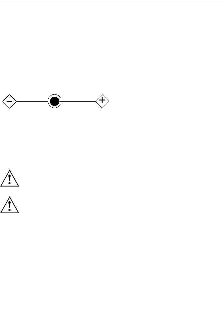
Manufacturer’s notes
DOC (Industry CANADA) notice
DOC(INDUSTRYCANADA)NOTICES
Radios and Television
This Class B digital apparatus meets all requirements of Canadian Interference-Causing Equipment
Regulations.
CET appareil numérique de la class B respecte toutes les exigence du Réglement
sur le matérial brouilleur du Canada.
UL Notice
This unit requires an AC adapter to operate. Only use UL Listed I.T.E. adapters with an output rating
of 19 VDC, with a minimum current of 3.42 (65W). The correct output rating is indicated on the
AC adapter label. Refer to the illustration below for the correct AC Adapter output polarity:
When using your notebook equipment, basic safety precautions should always be followed to
reduce the risk of fire, electric shock and injury to persons, including the following:
• Do not use this product near water for example, near a bathtub, washbowl, kitchen
sink or laundry tub, in a wet basement or near a swimming pool.
• Use only the power cord and batteries indicated in this manual. Do not dispose of batteries in a
fire. They may explode. Check with local codes for possible special disposal instructions.
For Authorized Repair Technicians Only
CAUTION:
For continued protection against risk of fire, replace only with the
same type and rating fuse.
WARNING:
Danger of explosion if Lithium (CMOS) battery is incorrectly replaced. Replace only
with the same or equivalent type recommended by the manufacturer.
Dispose of used batteries according to the manufacturer’s instructions.
FCC Regulatory information
Regulatoryinform ation
Federal Communications Commission statement
This device complies with Part 15 of FCC Rules. Operation is subject to the following
two conditions: (1) this device may not cause interference, and
(2) this device must accept any interference, including interference that may
cause undesired operation of this device.
FCC Interference Statement
This equipment has been tested and found to comply with the limits for a Class B digital
device, pursuant to Part 15 of the FCC Rules. These limits are designed to provide reasonable
protection against harmful interference in a residential installation. This equipment generates,
uses, and can radiate radio frequency energy. If not installed and used in accordance with
the instructions, it may cause harmful interference to radio communications.
78 Fujitsu

Manufacturer’s notes
However, there is no guarantee that interference will not occur in a particular installation.
If this equipment does cause harmful interference to radio or television reception, which
can be determined by turning the equipment off and on, the user is encouraged to try to
correct the interference by one or more of the following measures:
1. Reorient or relocate the receiving antenna.
2. Increase the distance between the equipment and the receiver.
3. Connect the equipment to an outlet on a circuit different from the one the receiver is connected to.
4. Consult the dealer or an experienced radio/TV technician for help.
Please note the following regulatory information related to the optional radio device.
FCC Radio Frequency Exposure statement
This radio device has been evaluated under FCC Bulletin OET 65C and found compliant with the
requirements as set forth in CFR 47 Sections 2.1091, 2.1093, and 15.247 (b) (4) addressing RF
Exposure from radio frequency devices. The radiated output power of this radio device is far below
the FCC radio frequency exposure limits. Nevertheless, this device shall be used in such a manner
that the potential for human contact during normal operation is minimized. When using this device, a
certain separation distance between antenna and nearby persons must be maintained to ensure RF
exposure compliance. In order to comply with RF exposure limits established in the ANSI C95.1
standards, the distance between the antennas and the user should not be less than 20 cm (8 inches).
Regulatory Notes and Statements
Radio device, health and authorisation for use
Radio-frequency electromagnetic energy is emitted from the wireless devices. The energy levels
of these emissions, however, are far much less than the electromagnetic energy emissions from
wireless devices such as mobile phones. Radio devices are safe for use by consumers because
they operate within the guidelines found in radio frequency safety standards and recommendations.
The use of the radio devices may be restricted in some situations or environments, such as:
• on board an airplane, or
• in an explosive environment, or
• in situations where the interference risk to other devices or services is
perceived or identified as harmful.
In cases in which the policy regarding use of radio devices in specific environments is not
clear (e.g., airports, hospitals, chemical/oil/gas industrial plants, private buildings), obtain
authorization to use these devices prior to operating the equipment.
Regulatory Information/Disclaimers
Export restrictions
This product or software contains encryption code which may not be exported or
transferred from the US or Canada without an approved US Department of Commerce
export license. This device complies with Part 15 of FCC Rules, as well as ICES 003 B
/ NMB 003 B. Operation is subject to the following two conditions:
(1) this device may not cause harmful interference, and
(2) this device must accept any interference received, including interference
that may cause undesirable operation.
Modifications not expressly authorized by Fujitsu may invalidate the user’s
right to operate this equipment.
Fujitsu 79

Manufacturer’s notes
ENERGY STAR Compliance
Your Fujitsu system is an ENERGY STAR qualified mobile PC. By choosing a computer with the
latest energy-saving technology, you’re helping to preserve our environment for future generations.
ENERGY STAR is a joint program of the U.S. Environmental Protection Agency, U.S. Department
of Energy, Natural Resources Canada, and other governments around the world helping us save
money while protecting the environment through energy efficient products and practices. With
energy costs and global warming top-of-mind for consumers, Fujitsu is committed to offering
solutions that help consumers conserve energy and improve the quality of our environment.
Sleep Mode:
You will notice that your computer is initially set so that the display turns off after 15 minutes of
user inactivity, and the computer goes into Sleep mode after 20 minutes of user inactivity. When
going into Sleep mode, the computer also reduces the speed of any active Ethernet network
links. To “wake” the computer from Sleep mode, press the Suspend/Resume Button.
Energy saving benefits:
Fujitsu ENERGY STAR qualified mobile PCs use about half as much electricity as standard
equipment – saving half in utility costs. But more than that, ENERGY STAR also makes a difference
for the environment. Did you know that the average house can be responsible for twice the
greenhouse gas emissions as the average car? That’s because every time you flip on a light
switch, run your dishwasher, or turn on your PC, you use energy, which means more greenhouse
gas emissions from power plants. So the more energy we can save through energy efficiency,
the more we help to reduce greenhouse gases and the risks of global warming.
To learn more about the important ENERGY STAR program, visit:"www.energystar.gov".
To read about how Fujitsu is supporting Sustainable Management along with
several other environmental activities, visit the Fujitsu Corporate Citizenship page at:
"http://www.computers.us.fujitsu.com/www/content/aboutus/environmental/environment.php".
80 Fujitsu

Index
Index
A
A beep sounds every second 93
Acoustic error messages 97
Anti-theft protection 69
Audio devices, connecting 81
Audio ports 81
B
Backspace 38
Bass loudspeaker (subwoofer) 58
Battery
battery life 45
caring for and maintaining 45
charge level 45, 54
charging 45
self-discharge 45
storage 45
Battery status meter 45
Battery:
discharges too quickly 97
BIOS Setup Utility
calling 90
exiting 91
operating 90
protecting with password 70
settings 90
Bluetooth
Switching off module 60
Switching on module 60
Bluetooth, safety notes 12
Board 82
Buffer battery, load 93
Buttons 37
C
Caps Lock 38
CD/DVD indicator 51
CD/DVD:
manual emergency removal 52
CE marking 102
Charging capacity, battery 45
Cleaning 14
Components
installing / removing 82
Configuration, BIOS Setup Utility 90
Connecting audio devices 81
Connecting headphones 81
Crystal View display
cleaning 14
Cursor control keys 38
Cursor keys 38
D
Date is incorrect 93
Declaration of conformity 102
Device
setting up 16
Devices
connecting 75
disconnecting 75
Display orientation
selecting 24
DOC (INDUSTRY CANADA) NOTICES 104
Drive
Removing 49
E
Emergency removal of data carrier 52
Energy
energy saving 13
Energy saving 13
Energy saving mode
leaving 96
Enter 38
Enter key 38
Error message:
on the screen 97
Error messages on the screen 97
Errors
Acoustic warnings 97
ESD 82
Ethernet LAN 62
ExpressCard 57
F
Fault
correction 92
Fingerprint sensor 69
configure 69
First-time setup 15
Fn + F10 41
Fn key 38
Fn+F3 40
Fn+F4 40
Fn+F6 40
Fn+F7 40
Fn+F8 40
Fn+F9 40
108 Fujitsu

Index
G
Getting started 15
H
Handling
data carriers 50
Hardware configuration 90
HDMI port 78
I
Important notes 12
Incorrect date/time 93
Inserting
a data carrier 51
K
Keyboard 37
cleaning 14
L
Landscape orientation
screen 24
LCD screen
cleaning 14
difficult to read 94
notes 28
reduce brightness 40
reflected glare 94
remains blank 93
LCD screen is too dark 93
Life, battery 45
Line feed 38
Loudspeaker
switch off 40
switch on 40
Loudspeakers 58
M
Main memory
see Adding memory 83
Mains adapter
connecting 16
setting up 16
Manual removal of data carrier 52
Mechanical backup 69
Memory card
handling 55
inserting 55
removing 56
Memory expansion
installing 85
removing 84
Memory module
important notes 83
installing 85
removing 84
Microphone 58
Microphone, connecting 81
Mobile operation 13
Module
Removing 49
Module bay 49
Modules 49
Monitor
connecting 76
drifting display 94
remains blank 94
Monitor port
see VGA connection socket 76
N
Notebook
before you travel 13
cannot be started 95
cleaning 14
stops working 96
switching off 26
transporting 13–14
using 18
Notebook, operation 18
Notebook: switching on 21
Notes 12
boards 82
cleaning 14
disposal / recycling 102
energy saving 13
LCD screen 28
Safety 12
transport 13
Num Lock
indicator 39
Numeric keypad 37
see Virtual numeric keypad 39
O
Operating system
activating system protection 71
cancel system protection 71
protecting with password 71
Optical drive 50
P
Packaging 15
Fujitsu 109

Index
Password
changing 71
entering 70
removing 71
Password protection 70
Password protection:
hard disk 72
Peripheral devices
connecting 75
disconnecting 75
Port Replicator
Ports 63
Portrait orientation
screen 24
Ports
Port Replicator 63
Power
power consumption 54
power-management features 54
Power-on indicator 21
Preparing for operation 16
Printer does not print 96
R
Radio component:
safety notes 12
Rechargeable battery 45
see Battery 45
Regulatory information
notebooks with radio device 106
Notebooks without radio device 103
Removing
a data carrier 51
Removing memory
see Adding memory 83
Return 38
S
Safety notes 12
Screen
no screen display 94
Screen brightness
increase 40
reduce 40
Screen port
see VGA connection socket 76
Security functions 68
Security Lock 69
Selecting a location 16
Self-discharge, battery 45
Servicing 82
Setup
see BIOS Setup Utility 90
Shift 38
Shift key 38
Shift+Tab 41
Slot
ExpressCard 57
Memory cards 55
Start key 38
Status indicators 18
Summer time 93
Supervisor password
changing 71
entering 70
removing 71
Suspend/Resume button 21
Switchingonforthefirst time 17
Symbols
indicators 18
System configuration 90
System expansion 83
see Adding memory 83
System settings, BIOS Setup Utility 90
T
Ta b b a c k 4 1
Tab key 38
The radio connection to a network does
not work 96
Time not correct 93
Time, daylight savings 93
Tips 92
Toggle output screen 41
Touchpad 35, 40
buttons 35
cleaning 14
dragging items 36
executing commands 35
moving the pointer 35
selecting an item 35
switch off 40
Touchpad buttons 40
TPM 74
Transport
Transport damage 15
Transportation 13–14
Travel, notebook 13
Troubleshooting 92
Trusted Platform Module 74
U
UMTS 61
Antenna 61
110 Fujitsu

Index
USB charging function 80
USB ports 79
User password
changing 71
entering 70
removing 71
Using the Kensington Lock Cable 69
V
VGA connection socket 76
Virtual numeric keypad 39
Volume
decrease 40
increase 40
Volume control 58
W
Webcam 44
Weight Saver
Removing 49
Wireless LAN
Switching off module 60
Switching on module 60
Wireless LAN:
safety notes 12
Fujitsu 111
1
Appendix:
Miscellaneous Information
This appendix contains a variety of information that you will find
useful in operating your Fujitsu LIFEBOOK. The appendix consists of
three sections, as follows:
Fingerprint Sensor Device
The fingerprint sensor is a handy device that lets you avoid having
to enter a username and password every time you want to:
• Log onto Windows
• Resume from sleep mode
• Cancel a password-protected screen saver
• Log into homepages that require a username and password
Restoring Your System Image and Software
This section contains important information about saving your
system’s Factory Image. It also outlines several other important
procedures, such as making a system image, restoring your Factory
Image and system images, managing your images, and restoring
the partitions on a hard drive.
WLAN User’s Guide
This section describes the procedures required to properly set up
and configure the integrated Wireless LAN Mini-PCI device (referred
to as "WLAN device" in the rest of the manual). Before using the
WLAN device, read this section carefully to ensure the device’s
correct operation. Keep this manual in a safe place for future
reference.
Appendix -T734.fm Page 1 Saturday, September 21, 2013 1:38 PM
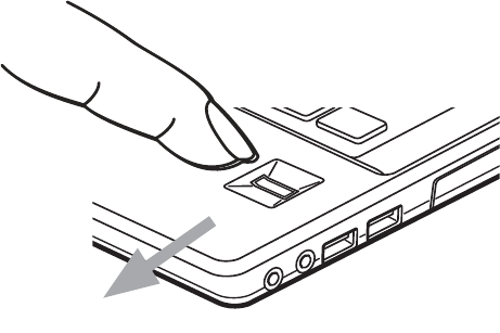
2
Fingerprint Sensor Device
Introducing the Optional Fingerprint Sensor
Device
The fingerprint sensor uses Softex OmniPass which provides
password management capabilities to Microsoft Windows
operating systems. OmniPass enables you to use a "master
password" for all Windows, applications, and on-line passwords.
With a fingerprint sensor, you can avoid having to enter a
username and password every time you want to:
• Log onto Windows
• Resume from sleep mode
• Cancel a password-protected screen saver
• Log into homepages that require a username and password
After you have “enrolled” - or registered - your fingerprint, you can
simply swipe your fingertip over the sensor for the system
recognize you.
Figure 1. Fingerprint Sensor
Appendix -T734.fm Page 2 Saturday, September 21, 2013 1:38 PM
3
OmniPass requires users to authenticate themselves using the
fingerprint sensor before granting access to the Windows desktop.
This device results in a secure authentication system for restricting
access to your computer, applications, web sites, and other
password-protected resources.
OmniPass presents a convenient graphical user interface, through
which you can securely manage passwords, users, and multiple
identities for each user.
Getting Started
This section guides you through the preparation of your system for
the OmniPass fingerprint recognition application. You will be led
through the OmniPass installation process. You will also be led
through the procedure of enrolling your first user into OmniPass.
Installing OmniPass
If OmniPass has already been installed on your system, skip this
section and go directly to “User Enrollment” on page 6. You can
determine whether OmniPass has already been installed by
checking to see if the following are present:
• The gold key-shaped OmniPass icon in the system tray at the
bottom right of the screen in the notification area.
• The Softex program group in the Programs group of the Start
menu
System Requirements
The OmniPass application requires space on your hard drive; it also
requires specific Operating Systems (OS’s). The minimum
requirements are as follows:
• Windows XP Professional or later operating system
• At least 60 MB available hard disk space
• Internet Explorer v6.0 or later
Installing the OmniPass Application
If OmniPass is already installed on your system, go to “User
Enrollment” on page 6
.
Otherwise continue with this section on
software installation.
Appendix -T734.fm Page 3 Saturday, September 21, 2013 1:38 PM

4
1 To install OmniPass on your system you must run the Bonus
Apps tool as detailed in the Starting section of this manual.
Once Bonus Apps have been installed, you may be prompted to
restart you system. Once your system has rebooted you will be
able to use OmniPass. If you choose not to restart immediately
after installation, OmniPass will not be available for use until
the next reboot.
2 The installation program automatically places an icon (Softex
OmniPass) in the Windows Control Panel as well as a golden key
shaped icon in the taskbar notification area.
Verifying Information about OmniPass
After you have completed installing OmniPass and restarted your
system, you may wish to check the version of OmniPass on your
system.
To check the version information of OmniPass:
1 From the Windows Desktop, double-click the key-shaped
OmniPass icon in the taskbar’s notification area (usually located
in the lower right corner of the screen),
or,
Windows 7: Click Start on the Windows taskbar. Select Control
Panel.
Windows 8: From the Modern Start screen, right-click and select
"All Apps", then select Control Panel.
Double-click Softex OmniPass in the Control Panel, and the
OmniPass Control Center will appear. If it does not appear, then
FOR INSTALLATION, OMNIPASS REQUIRES THAT THE USER INSTALLING
OMNIPASS HAVE ADMINISTRATIVE PRIVILEGES TO THE SYSTEM AND THE
SYSTEM SHOULD HAVE THE FINGERPRINT DEVICE. IF YOUR CURRENT USER
DOES NOT HAVE ADMINISTRATIVE PRIVILEGES, LOG OUT AND THEN LOG IN
WITH AN ADMINISTRATOR USER BEFORE PROCEEDING WITH OMNIPASS
INSTALLATION.
Appendix -T734.fm Page 4 Saturday, September 21, 2013 1:38 PM

5
the program is not properly installed,
or,
Windows 7: Click the Start button, select Programs, and from
the submenu select the Softex program group, from that
submenu click OmniPass Control Center.
2 Version information is listed on the left side of OmniPass Control
Center window.
Uninstalling OmniPass
To remove the OmniPass application from your system:
1 Windows 7: Click Start on the Windows taskbar. Select Control
Panel.
Windows 8: From the Modern Start screen, right-click and select
"All Apps", then select Control Panel.
2 Double-click Add/Remove Programs (In Windows 7: Programs
and Features).
3 Select OmniPass, and then click Uninstall.
4 Follow the directions to uninstall the OmniPass application.
5 Once OmniPass has finished uninstalling, reboot your system
when prompted.
FOR UNINSTALLATION, OMNIPASS REQUIRES THAT THE USER UNINSTALLING
OMNIPASS HAVE ADMINISTRATIVE PRIVILEGES TO THE SYSTEM. IF YOUR
CURRENT USER DOES NOT HAVE ADMINISTRATIVE PRIVILEGES, LOG OUT AND
THEN LOG IN WITH AN ADMINISTRATOR USER BEFORE PROCEEDING WITH
OMNIPASS UNINSTALLATION.
Appendix -T734.fm Page 5 Saturday, September 21, 2013 1:38 PM
6
User Enrollment
Before you can use any OmniPass features you must first enroll a
user into OmniPass.
Master Password Concept
Computer resources are often protected with passwords. Whether
you are logging into your computer, accessing your email, e-
banking, paying bills online, or accessing network resources, you
often have to supply credentials to gain access. This can result in
dozens of sets of credentials that you have to remember.
During user enrollment a "master password” is created for the
enrolled user. This master password “replaces” all other passwords
for sites you register with OmniPass.
Example: A user, John, installs OmniPass on his system (his home
computer) and enrolls an OmniPass user with username “John_01”
and password “freq14”. He then goes to his webmail site to log onto
his account. He inputs his webmail credentials as usual (username
“John_02” and password “lifebook”), but instead of clicking
[Submit], he directs OmniPass to Remember Password. Now
whenever he returns to that site, OmniPass will prompt him to
supply access credentials.
John enters his OmniPass user credentials (“John_01” and “freq14”)
in the OmniPass authentication prompt, and is allowed into his
webmail account. He can do this with as many sites or password-
protected resources he likes, and he will gain access to all those
sites with his OmniPass user credentials (“John_01” and “freq14”).
This is assuming he is accessing those sites with the system onto
which he enrolled his OmniPass user. OmniPass does not actually
change the credentials of the password protected resource. If John
were to go to another computer without he OmniPass account to
access his webmail, he would need to enter his original webmail
credentials (“John_02” and “lifebook”) to gain access. If he attempts
his OmniPass user credentials on a system other than a system he’s
enrolled on, he will not gain access.
Appendix -T734.fm Page 6 Saturday, September 21, 2013 1:38 PM
7
Basic Enrollment
The Enrollment Wizard will guide you through the process of
enrolling a user. Unless you specified otherwise, after OmniPass
installation the Enrollment Wizard will launch on Windows login. If
you do not see the Enrollment Wizard, you can bring it up by clicking
Start on the Windows taskbar; select Programs; select Softex; click
Enroll a new user.
1Click [Enroll an existing Windows user] to proceed to
username and password verification. By default, the OmniPass
Enrollment Wizard enters the credentials of the currently logged
in Windows user. (Note: Click [Create and Enroll a new
Windows user] to create a new Windows user account and
enroll that user into OmniPass.)
2 Enter the password you use to log in to Windows. This will
become the “master password” for this user. In most cases, the
Domain: value will be your Windows computer name. In
corporate environments, or when accessing corporate resources,
the Domain: may not be your Windows computer name. Click
[Next] to continue.
3 In this step OmniPass captures your fingerprint. Refer to
“Enrolling a Fingerprint” on page 8 for additional information.
4 Next, choose how OmniPass notifies you of various events. We
recommend you keep Taskbar Tips on Beginner mode taskbar
tips and Audio Tips on at least Prompt with system beeps only
until you get accustomed to how OmniPass operates. Click
[Next] to proceed with user enrollment. You will then see a
Congratulations screen indicating your completion of user
enrollment.
5Click [Done] to exit the OmniPass Enrollment Wizard. You will be
asked if you’d like to log in to OmniPass with your newly enrolled
user; click [Yes].
Appendix -T734.fm Page 7 Saturday, September 21, 2013 1:38 PM
8
Enrolling a Fingerprint
Enrolling a fingerprint will increase the security of your system and
streamline the authentication procedure.
You enroll fingerprints in the OmniPass Control Center. With an
OmniPass user logged in, double-click the system tray OmniPass
icon. Select the User Settings tab and click Enrollment under the
User Settings area. Click Enroll Authentication Device and
authenticate at the authentication prompt to start device
enrollment.
1 During initial user enrollment, you will be prompted to select
the finger you wish to enroll. Fingers that have already been
enrolled will be marked by a green check. The finger you select
to enroll at this time will be marked by a red arrow. OmniPass
will allow you re-enroll a finger. If you choose a finger that has
already been enrolled and continue enrollment, OmniPass will
enroll the fingerprint, overwriting the old fingerprint. Select a
finger to enroll and click [Next].
2 It is now time for OmniPass to capture your selected fingerprint.
It may take a several capture attempts before OmniPass
acquires your fingerprint. Should OmniPass fail to acquire your
fingerprint, or if the capture screen times out, click [Back] to
restart the fingerprint enrollment process.
Your system has a “swipe” fingerprint sensor. A swipe sensor is
small and resembles a skinny elongated rectangle. To capture a
fingerprint, gently swipe or pull your fingertip over the sensor
(starting at the second knuckle) towards yourself. Swiping too
fast or too slow will result in a failed capture. The Choose Finger
screen has a [Practice] button; click it to practice capturing your
fingerprint. When you are comfortable with how your
fingerprint is captured, proceed to enroll a finger.
Appendix -T734.fm Page 8 Saturday, September 21, 2013 1:38 PM

9
3 Once OmniPass has successfully acquired the fingerprint, the
Verify Fingerprint screen will automatically appear. To verify
your enrolled fingerprint, place your fingertip on the sensor and
hold it there as if you were having a fingerprint captured.
Successful fingerprint verification will show a green fingerprint
in the capture window and the text Verification Successful
under the capture window.
4 After you finish enrolling and verifying your fingerprints, you
have the option to Enable PBA with enrolled finger. If you
enable this option, then you must choose two fingers to save in
PBA. If you have enrolled successfully, the Finger Enrollment
Status in PBA screen will state Finger saved in PBA successfully.
Using OmniPass
You are now ready to begin using OmniPass. Used regularly,
OmniPass will streamline your authentications.
Password Replacement
You will often use the password replacement function. When you go
to a restricted access website (e.g., your bank, your web-based
email, online auction or payment sites), you are always prompted
to enter your login credentials. OmniPass can detect these prompts
and you can teach OmniPass your login credentials. The next time
you go to that website, you can authenticate with your fingerprint
to gain access.
OmniPass Authentication Toolbar
After installing OmniPass and restarting, you will notice a dialog
you have not seen before at Windows Logon. This is the OmniPass
Authentication Toolbar, and it is displayed whenever the OmniPass
authentication system is invoked. The authentication system may
IF YOU ENABLE PBA ON YOUR SYSTEM, YOU MUST SET THE SUPERVISOR
PASSWORD AND PASSWORD ON BOOT SETTINGS. SEE “HARD DISK DRIVE
PASSWORDS” ON PAGE 51 FOR ADDITIONAL INFORMATION.
Appendix -T734.fm Page 9 Saturday, September 21, 2013 1:38 PM
10
be invoked frequently: during Windows Logon, during OmniPass
Logon, when unlocking your workstation, when resuming from
sleep or hibernate, when unlocking a password-enabled
screensaver, during password replacement for remembered site or
application logins. When you see this toolbar, you are being
prompted to authenticate.
The Logon Authentication window indicates what OmniPass-
restricted function you are attempting. Icons in the lower left
(fingerprint and key) show what authentication methods are
available to you. Selected methods are highlighted while
unselected methods are not. When you click the icon for an
unselected authentication method, the authentication prompt
associated with that method is displayed.
When prompted to authenticate, you must supply the appropriate
credentials: an enrolled finger for the fingerprint capture window or
your master password for the master password prompt (the key
icon).
Remembering a Password
OmniPass can remember any application, GUI, or password
protected resource that has a password prompt.
Using the following procedure, you can store a set of credentials into
OmniPass. These credentials will then be linked to your “master
password” or fingerprint.
Go to a site that requires a login (username and password), but
do
not log in yet.
At the site login prompt, enter your username and
password in the prompted fields, but
do not enter the site
(do not
hit [Enter], [Submit], [OK], or Login). Right-click the OmniPass
system tray icon and select Remember Password from the
submenu. The Windows arrow cursor will change to a golden key
OmniPass cursor. Click the OmniPass cursor in the login prompt
area, but don’t click [Login] or [Submit].
Appendix -T734.fm Page 10 Saturday, September 21, 2013 1:38 PM

11
Associating a Friendly Name
After clicking the OmniPass key cursor near the login prompt,
OmniPass will prompt you to enter a “friendly name” for this site.
You should enter something that reminds you of the website, the
company, or the service you are logging into. In its secure database,
OmniPass associates this friendly name with this website.
Additional Settings for Remembering a Site
When OmniPass prompts you to enter a “friendly name” you also
have the opportunity to set how OmniPass authenticates you to this
site. There are three effective settings for how OmniPass handles a
remembered site.
The default setting is Automatically click the “OK” or “Submit”
button for this password protected site once the user is
authenticated. With this setting, each time you navigate to this site
OmniPass will prompt you for your master password or fingerprint
authentication device. Once you have authenticated with
OmniPass, you will automatically be logged into the site.
Less secure is the option to Automatically enter this password
protected site when it is activated. Do not prompt for
authentication. Check the upper box to get this setting, and each
time you navigate to this site OmniPass will log you into the site
without prompting you to authenticate.
If you uncheck both boxes in Settings for this Password Site,
OmniPass will prompt you for your master password or fingerprint
authentication device. Once you have authenticated with OmniPass
THIS SETTING IS MORE CONVENIENT IN THAT WHENEVER YOU GO TO A SITE
REMEMBERED WITH THIS SETTING, YOU WILL BYPASS ANY
AUTHENTICATION PROCEDURE AND GAIN INSTANT ACCESS TO THE SITE.
BUT SHOULD YOU LEAVE YOUR SYSTEM UNATTENDED WITH YOUR
OMNIPASS USER LOGGED IN, ANYONE USING YOUR SYSTEM CAN BROWSE
TO YOUR PASSWORD PROTECTED SITES AND GAIN AUTOMATIC ACCESS.
Appendix -T734.fm Page 11 Saturday, September 21, 2013 1:38 PM

12
your credentials will be filled in to the site login prompt, but you will
have to click the website [OK], [Submit], or [Login] button to gain
access to the site.
Click Finish to complete the remember password procedure. The
site location, the credentials to access the site, and the OmniPass
authentication settings for the site are now stored in the OmniPass
secure database. The OmniPass authentication settings (Settings
for this Password Site) can always be changed in Vault
Management.
Logging in to a Remembered Site
Whether or not OmniPass prompts you to authenticate when you
return to a remembered site is determined by Settings for this
Password Site and can be changed in Vault Management.
The following cases are applicable to using OmniPass to login to:
Windows, remembered web sites, and all other password protected
resources.
With Master Password
Once you return to a site you have remembered with OmniPass, you
may be presented with a master password prompt. Enter your
master password and you will be allowed into the site.
Logging into Windows with a Fingerprint Device
When logging into Windows with a fingerprint device, the
fingerprint capture window will now appear next to the Windows
Login screen. Place your enrolled fingertip on the sensor to
authenticate. You will be simultaneously logged into Windows and
OmniPass. The capture window will also appear if you have used
Ctrl-Alt-Del to lock a system, and the fingerprint device can be used
to log back in as stated above.
IF A MACHINE IS LOCKED AND OMNIPASS DETECTS A DIFFERENT USER
LOGGING BACK IN WITH A FINGERPRINT, THE FIRST USER WILL BE LOGGED
OUT AND THE SECOND USER LOGGED IN.
Appendix -T734.fm Page 12 Saturday, September 21, 2013 1:38 PM
13
Password Management
OmniPass provides an interface that lets you manage your
passwords. To access this GUI, double-click the OmniPass key in the
system tray. Click Vault Management; you will be prompted to
authenticate. Once you gain access to Vault Management, click
Manage Passwords under Vault Settings. You will see the Manage
Passwords interface, with a list of friendly names.
You can view the credentials stored for any remembered website by
highlighting the desired resource under Password Protected
Dialog and clicking Unmask Values. Should a password be reset, or
an account expire, you can remove stored credentials from
OmniPass. Highlight the desired resource under Password
Protected Dialog and click Delete Page. You will be prompted to
confirm the password deletion.
The two check boxes in Manage Passwords govern whether
OmniPass prompts you to authenticate or directly logs you into the
remembered site.
OmniPass will overwrite an old set of credentials for a website if you
attempt to use Remember Password on an already remembered
site.
The exception to the above rule is when resetting the Windows
password. If your password is reset in Windows, the next time you
login to Windows, OmniPass will detect the password change and
prompt you to “Update” or “Reconfirm” the password with
OmniPass. Enter your new Windows password in the prompt and
click OK. Your OmniPass "master password" will still be your
Windows password.
OmniPass User Identities
Identities allow OmniPass users to have multiple accounts to the
same site (e.g.,
bob@biblomail.com
and
boballen@biblomail.com
). If OmniPass did not provide you
identities, you would be limited to remembering one account per
site.
Appendix -T734.fm Page 13 Saturday, September 21, 2013 1:38 PM

14
To create and manage identities, double-click the OmniPass key in
the system tray. Click Vault Management; OmniPass will prompt
you to authenticate. Once you gain access to Vault Management,
click Manage Identities under Vault Settings. You can only
manage the identities of the currently logged in OmniPass user
To add a new identity, click New Identity or double-click Click here
to add a new identity. Name the new identity and click [OK], then
click [Apply]. You can now switch to the new identity and start
remembering passwords.
To delete an identity, highlight the identity you want to delete and
click [Delete Identity], then click [Apply].
To set the default identity, highlight the identity you want as
default and click [Set as Default]; click [Apply] to ensure the
settings are saved. If you log in to OmniPass with a fingerprint
device, you will automatically be logged in to the default identity
for that OmniPass user. You can choose the identity with which you
are logging in if you login using "master password".
Choosing User Identity during Login
To choose your identity during login, type your username in the
User Name: field. Press [Tab] and see that the Domain: field self-
populates. Click the Password: field to bring the cursor to it, and you
will see the pull-down menu in the Identity: field. Select the
identity to login as, then click OK.
Switch User Identity
To switch identities at any time, right-click the OmniPass system
tray icon and click Switch User Identity from the submenu. The
Switch Identity dialog will appear. Select the desired identity and
then click OK.
WHEN YOU DELETE AN IDENTITY, ALL OF ITS ASSOCIATED REMEMBERED
SITES AND PASSWORD PROTECTED DIALOGS ARE LOST.
Appendix -T734.fm Page 14 Saturday, September 21, 2013 1:38 PM

15
Identities and Password Management
On the Manage Passwords interface of the Vault Management tab
of the OmniPass Control Center, there is a pull-down selection box
labeled, Identity. This field lets you choose which identity you are
managing passwords for. When you select an identity here, only
those password protected dialogs that are associated with that
identity are shown. You can perform all the functions explained in
“Password Management” on page 13.
Configuring OmniPass
This section gives an overview of both the Export/Import function
and the OmniPass Control Center.
Exporting and Importing Users
Using OmniPass Control Center, you can export and import users in
and out of OmniPass. The export process backs up all remembered
sites, credentials, and enrolled fingerprints for an OmniPass user.
All OmniPass data for a user is backed up to a single encrypted
database file. During the import process, the Windows login of the
exported user is required. If the proper credentials cannot be
supplied, the user profile will not be imported.
YOU CANNOT IMPORT A USER INTO OMNIPASS IF THERE ALREADY IS A USER
WITH THE SAME NAME ENROLLED IN OMNIPASS.
Appendix -T734.fm Page 15 Saturday, September 21, 2013 1:38 PM

16
Exporting an OmniPass User Profile
To export a user, open the OmniPass Control Center, and click
Import/Export User under Manage Users.
Click Exports an OmniPass user profile. OmniPass will prompt you
to authenticate. Upon successfully authentication, you must name
the OmniPass user profile and decide where to save it. An .opi file is
generated, and you should store a copy of it in a safe place.
This .opi file contains all your user specific OmniPass data, and it is
both encrypted and password protected. This user profile does NOT
contain any of your encrypted data files.
Importing an OmniPass User Profile
To import an OmniPass user open the OmniPass Control Center, and
click Import/Export User under Manage Users. Click Imports a new
user into OmniPass and then select OmniPass Import/Export File
(*.opi) and click Next. OmniPass will then prompt you to browse for
the file you had previously exported (.opi file). When you select the
.opi file for importation, OmniPass will prompt you for
authentication. The credentials that will allow a user profile to be
imported are the Windows login credentials of the exported user.
They are the credentials that had to be submitted when the user
•YOU SHOULD PERIODICALLY EXPORT YOUR USER PROFILE AND STORE IT IN
A SAFE PLACE. IF ANYTHING HAPPENS TO YOUR SYSTEM, YOU CAN IMPORT
YOUR OMNIPASS PROFILE TO A NEW SYSTEM AND HAVE ALL YOUR
REMEMBERED SETTINGS AND FINGERPRINTS INSTANTLY.
•Y
OU DON'T FORGET THE WINDOWS LOGIN CREDENTIALS WHEN
EXPORTING. WHEN YOU EXAMINE THE IMPORTATION, YOU ARE
PROMPTED FOR AUTHENTICATION. THE CREDENTIALS THAT WILL ALLOW A
USER PROFILE TO BE IMPORTED ARE THE WINDOWS LOGIN CREDENTIALS
OF THE EXPORTED USER. THEY ARE THE CREDENTIALS THAT HAD TO BE
SUBMITTED WHEN THE USER PROFILE WAS EXPORTED. YOU WILL NEED
USER NAME, PASSWORD, AND DOMAIN.
Appendix -T734.fm Page 16 Saturday, September 21, 2013 1:38 PM
17
profile was exported. You will need User Name, Password, and
Domain. If you don’t remember the value for Domain, in a PC or
SOHO environment Domain should be your computer name.
OmniPass will notify you if the user was successfully imported.
Things to Know Regarding Import/Export
• Assume you export a local Windows User profile from
OmniPass. You want to import that profile to another
machine that has OmniPass. Before you can import the
profile, a Windows user with the same login credentials must
be created on the machine importing the profile.
Example: I have a Windows user with the username “Tom”
and the password “Sunshine” on my system. I have enrolled
Tom into OmniPass and remembered passwords. I want to
take all my passwords to new system. I export Tom’s
OmniPass user profile. I go to my new system and using the
Control Panel I create a user with the username "Tom" and the
password "Sunshine". I can now successfully import the
OmniPass user data to the new system.
• If you export an OmniPass-only user, you can import that user
to any computer running OmniPass, provided that a user with
that name is not already enrolled in OmniPass.
• If you attempt to import a user profile who has the same
name as a user already enrolled in OmniPass, the OmniPass
import function will fail.
OmniPass Control Center
This section will serve to explain functions within the OmniPass
Control Center that weren’t explained earlier.
You can access the OmniPass Control Center any of three ways:
• Double-click the golden OmniPass key shaped icon in the
Windows taskbar (typically in the lower-right corner of the
desktop)
•Click the Start button; select the Programs group; select the
Softex program group; and click the OmniPass Control
Center selection.
Appendix -T734.fm Page 17 Saturday, September 21, 2013 1:38 PM

18
• Open the Windows Control Panel (accessible via [Start] >
Settings > Control Panel) and double-click the Softex
OmniPass icon.
User Management
The User Management tab has two major interfaces: Add/Remove
User and Import/Export User. Import/Export User functionality is
documented in “Exporting and Importing Users” on page 15. Add/
Remove User functionality is straightforward.
If you click Adds a new user to OmniPass you will start the
OmniPass Enrollment Wizard. The Enrollment Wizard is
documented in “User Enrollment” on page 6.
If you click Removes a user from OmniPass, OmniPass will prompt
you to authenticate. Authenticate with the credentials (or enrolled
fingerprint) of the user you wish to remove. OmniPass will prompt
you to confirm user removal. Click OK to complete user removal.
User Settings
The User Settings tab has four interfaces: Audio Settings, Taskbar
Tips, and Enrollment. User settings allow users to customize
OmniPass to suit their individual preferences. Under User Settings
(Audio Settings and Taskbar Tips) you can set how OmniPass
notifies the user of OmniPass events (e.g., successful login, access
denied, etc.). The details of each setting under the Audio Settings
and Taskbar Tips interfaces are self-explanatory.
The Enrollment interface allows you to enroll fingerprints. For the
procedure to enroll and authentication device refer to
Chapter 2.3
.
To enroll additional fingerprints, click Enroll Authentication
Device, and authenticate with OmniPass. Select the fingerprint
REMOVING A USER WILL AUTOMATICALLY DESTROY ALL OMNIPASS DATA
ASSOCIATED WITH THAT USER. ALL IDENTITIES AND CREDENTIALS
ASSOCIATED WITH THE USER WILL BE LOST.
IF YOU’RE SURE YOU WANT TO REMOVE THE USER, WE RECOMMEND YOU
EXPORT THE USER PROFILE.
Appendix -T734.fm Page 18 Saturday, September 21, 2013 1:38 PM
19
recognition device in the Select Authentication Device screen (it
should already be marked by a green check if you have a finger
enrolled) and click Next.
System Settings
The OmniPass Startup Options interface can be found in the
System Settings tab. With these options you can specify how your
OmniPass Logon is tied to your Windows Logon.
The first option, Automatically log on to OmniPass as the current
user, will do just as it says; during Windows login, you will be logged
on to OmniPass using your Windows login credentials. If the user
logging into Windows was never enrolled into OmniPass, upon
login no one will be logged on to OmniPass. This setting is
appropriate for an office setting or any setting where users must
enter a username and password to log into a computer. This is the
default setting.
With the second option, Manually log on to OmniPass at startup,
OmniPass will prompt you to login once you have logged on to
Windows.
With the third option, Do not log on to OmniPass at startup,
OmniPass will not prompt for a user to be logged on.
You can manually log on to OmniPass by right-clicking the
OmniPass taskbar icon and clicking Log in User from the right-click
menu.
Troubleshooting
You cannot use OmniPass to create Windows users. You must first
create the Windows user, and you will need administrative
privileges to do that. Once the Windows user is created, you can add
that user to OmniPass using the same username and password
Cannot add Windows users to OmniPass
If you experience difficulties adding a Windows user to OmniPass,
you may need to adjust your local security settings. You can do this
by going to Start, Control Panel, Administrative Tools, and Local
Security Settings. Expand Local Policies, expand Security
Appendix -T734.fm Page 19 Saturday, September 21, 2013 1:38 PM
20
Options, and double-click Network Access: Sharing and Security
Model for Local Accounts. The correct setting should be
Classic -
Local Users Authenticate as Themselves
.
Cannot add a User with a Blank Password to OmniPas
If you experience difficulties adding a user with a blank password to
OmniPass, you may need to adjust your local security settings. First
attempt the procedure explained in the
Cannot add Windows user
to OmniPass
section. If the difficulties persist, then try the following
procedure.
Click Start, Control Panel, Administrative Tools, and Local
Security Settings. Expand Local Policies, expand Security
Options, and double-click Accounts: Limit local account use of
blank passwords to console login only. This setting should be set
to Disabled.
Dialog appears after OmniPass authentication during Windows
Logon
After installing OmniPass on your system, you can choose to logon
to Windows using OmniPass. You authenticate with OmniPass (via
master password, or an enrolled security device) and OmniPass logs
you into Windows. You may, during this OmniPass authentication,
see a Login Error dialog box.
This dialog box occurs when OmniPass was unable to log you into
Windows with the credentials supplied (username and password).
This could happen for any of the following reasons:
• Your Windows password has changed
• Your Windows account has been disabled
If you are having difficulties due to the first reason, you will need to
update OmniPass with your changed Windows account password.
Click Update Password and you will be prompted with a dialog to
reconfirm your password.
Enter the new password to your Windows user account and click OK.
If the error persists, then it is unlikely the problem is due to your
Windows user account password changing.
Appendix -T734.fm Page 20 Saturday, September 21, 2013 1:38 PM
21
Restoring Your System Image
and Software
Depending upon which operating system you are using
(Windows 7 or Windows 8), there are slight differences in the
restoration procedures. The following procedure is for Windows
7 systems. Equivalent information for Windows 8 configurations
can be found at “Windows 8: Restoring Your System Image and
Software” on page 33.
Windows 7: Restoring Your System Image and
Software (Windows 7)
It is very important that you create DVD copies of your Factory
Image and Bootable Disc (along with other applicable media
such as application discs) before beginning to use your system.
To do so, follow the instructions in the “Saving Your Factory
Image” and “Creating Backup Images of Factory Image and
Discs” sections of this chapter.
Saving and Recovering Your Factory and System Images with My
Recovery
Along with instructions on saving your Factory Image, this
document outlines several other important procedures, such as
making a system image, restoring your Factory Image and system
images, managing your images, and restoring the partitions on a
hard drive.
Appendix -T734.fm Page 21 Saturday, September 21, 2013 1:38 PM

22
Saving your Factory Image
When you purchased your new system, a copy of the pre-installed
Factory Image was loaded into a hidden partition on your hard disk
drive. Having a copy of the original Factory Image available to you
means that in the event of system failure, you will be able to restore
it to its original state.
To make a copy of the Factory Image to DVD discs, you will need
several blank discs (DVD-R or DVD+R discs are recommended) to
create the copy. After creating the copy, be sure to label the discs
and keep them in a safe place to ensure they do not get damaged.
•IN ORDER TO INSTALL APPLICATIONS, MAKE COPIES OF FACTORY AND
SYSTEM IMAGES, AND BURN APPLICATION MEDIA AND BOOTABLE DISCS
YOU MUST HAVE AN INTERNAL OR EXTERNALLY CONNECTED
WRITABLE DVD DRIVE.
•I
T IS EXTREMELY IMPORTANT THAT YOU COPY YOUR FACTORY IMAGE TO
REMOVABLE MEDIA (E.G., DVD DISCS). FAILURE TO DO SO COULD
RESULT IN AN INABILITY TO RESTORE THE IMAGE AT A FUTURE DATE.
•W
E RECOMMEND THAT YOU USE DVD-R OR DVD+R DISCS FOR YOUR
BACKUP, BUT SUPPORTED MEDIA* FOR IMAGE BACKUPS INCLUDE:
FOR FACTORY IMAGE, APPLICATION DATA, AND BOOTABLE DISC: DVD-
R/+R.
FOR USER-CREATED BACKUP IMAGE: DVD-R/+R, DVD-RW/+RW,
DVD-DL.
* DEPENDING UPON YOUR OPTICAL DRIVE AND MEDIA FORMAT USED,
SOME MEDIA TYPES MAY BE INCOMPATIBLE FOR CREATING IMAGE
BACKUPS.
DUE TO CERTAIN LICENSING REQUIREMENTS, SOME THIRD-PARTY
APPLICATIONS WILL NEED TO BE INSTALLED SEPARATELY USING THE
APPLICATION MEDIA BUNDLED WITH YOUR SYSTEM.
Appendix -T734.fm Page 22 Saturday, September 21, 2013 1:38 PM

23
Creating Backup Images of Factory Image and Discs
1 On your desktop, there is a [My Recovery] icon that allows you
to make a backup image of the Factory image for later use.
Launch My Recovery from the desktop icon
2 Select [Manage/Create]-> [Factory Image].
The Backup Images menu displays a list from which you can
choose which type of disc you want to burn: Bootable Disc,
Applications Disc, or Recovery Disc.
3 Select
Recovery Disc
, then click [Make DVD].
4 Confirm that the # box has “2” (Note that in some cases the box
may display a larger number for the factory image, depending
upon its size.)
5 The message “Recovery Disc #1 will be created. Enter your
comments and the number of media on the DVD”. Click [YES] to
burn the Factory Image.
6 While the copy is being made, a “Writing to the media screen
displays a progress bar. When the copy is complete, a dialog will
appear informing you of the successful completion of the
backup.
7 Repeat the process for the remaining images on disc (Bootable
Disc and Applications Disc). The number of images available
may vary depending on your system model; some models do
not have the applications loaded on the hard drive.
•SOME CONFIGURATIONS OF CERTAIN STYLISTIC MODELS DO NOT HAVE
APPLICATIONS LOADED ON THE HARD DRIVE; RATHER, THEY ARE
AVAILABLE AT THE FUJITSU SUPPORT SITE FOR DOWNLOAD. PLEASE TAKE
THAT INTO ACCOUNT WHEN READING THE FOLLOWING PROCEDURES.
•A
LL USER-CREATED DATA WILL BE DELETED FROM YOUR SYSTEM WHEN
THE FACTORY IMAGE IS RESTORED.
Appendix -T734.fm Page 23 Saturday, September 21, 2013 1:38 PM

24
Recovering Your Factory Image
In the event you need to restore your original Factory Image,
perform the following steps. Note that there may be some third-
party applications that need to be installed from the application
media bundled with your system.
In order to recover your Factory Image, perform the steps outlined
in See “Running Recovery and Utility from hard disk” on page 27.
Creating a System Backup Image
Optional Step:
Launch the Fujitsu Bonus Apps utility from your
desktop, and select the components you wish to install.
User-Configured System Backups:
On your desktop,
there is a [MyRecovery] icon that allows you to make
backups of your current system image either to
another location on your hard drive or on removable
media. A system image is the configuration of your C:
drive at a particular point of time. You may want to make system
image backups occasionally in order to have points to which you can
return without having to go all the way back to the Factory Image.
By default, system images are saved in the MyRecovery folder
(either on D:\ or external hard drive, depending on your hardware
type).
1 Click the [MyRecovery] icon on your desktop. The My Recovery
screen will appear (See Figure 2). Note that the screen
illustrated may vary, depending upon your system
configuration.)
2 Click the [Backup] button on the MyRecovery screen.
ALL USER-CREATED DATA WILL BE DELETED FROM YOUR SYSTEM WHEN
THE FACTORY IMAGE IS RESTORED.
My Recovery
Appendix -T734.fm Page 24 Saturday, September 21, 2013 1:38 PM
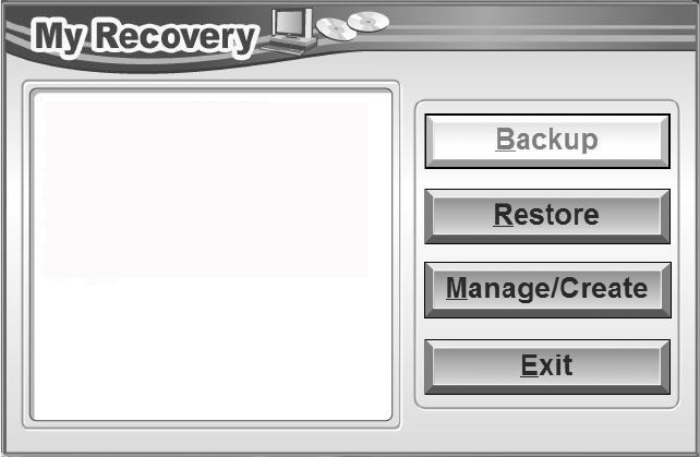
25
Figure 2. MyRecovery screen
3 On the next screen that appears, you can enter up to 200
characters of information about the backup file. This
information will help you to identify the image at a later date.
4 Click the [Next] button and the system will reboot.
5 After rebooting, the “Create the image” window appears, in
which you can either click [Create the image on D drive] or
[Select the drive] if you want to save to an external hard disk
drive. (Note that the [Create the image on D drive may not be
available on all configurations.)
6 An image appears showing you graphically how the image will
be stored. Click the [Next] button.
7 Click [Execute] to start the backup.
Managing Your Backup Images
With the MyRecovery tool you can also make copies of backup
images, archive them on DVD, or delete them from your hard drive.
Create a backup image of the C: drive!
A backup image will be created on D: drive (default).
My Recovery immediately restores the computer to the
point of time when the backup image is created. There
is no need to go through the complicated settings and
reinstallation of drivers and applications.
System restoration becomes simple and easy using
My Recovery!
Appendix -T734.fm Page 25 Saturday, September 21, 2013 1:38 PM
26
1 To begin, double-click the [MyRecovery] icon on your desktop.
2 Click the [Manage/Create] button in the MyRecovery window.
3 When the MyRecovery Manager window appears, click [Manage
Backup Images].
4 In the next window, a list of your backup images appears. Below
the list are three buttons allowing you to [Make DVD], [Copy], or
[Delete] your backup images.
5 Select an image title from the list, then click the action button
you would like to perform.
6 Note that you need to have an external disk drive connected for
the [Copy] button to be enabled. If you elect to copy the image,
you will be prompted to enter the destination. If you are ready
to copy, click [OK] to proceed. A progress screen appears while
the backup copy is being made.
7 Note that if you copy an image to an external hard drive, both
the original and the copy will appear in the [Backup Images]
window with identical names, dates, and file sizes, but with the
different drive letter to distinguish them. Before you select
[Make DVD], make sure you have a recordable DVD drive
connected and blank DVDs available.
Using the Recovery and Utility Tools
The Recovery and Utility tools consist of a variety of tools that will
help you recover your Factory Image, recover system images, and
delete the data from your hard disk.
Methods for accessing the utilities
Recovery and Utility Tools are preinstalled in a hidden partition by
the factory, or they can be accessed by using the bootable disc.
Please note that you can delete Recovery and Utility tools from your
hard disk drive if you modify the partitions. In this case you will not
be able to use the hidden partition for booting to Recovery and
Utility Tools, but you will still be able to boot from the Bootable Disc.
Appendix -T734.fm Page 26 Saturday, September 21, 2013 1:38 PM
27
Determining whether Recovery and Utility is pre-loaded
1 Turn on or reboot your system. When the Fujitsu logo appears,
press [F12] key. The Boot Menu will appear.
2 Press the Tab key to select Application menu.
3 Check whether the <Recovery and Utility> option is present. If it
is not present, it means that the utility must be used from the
disc. Proceed to “Running Recovery and Utility from the
Bootable Disc” if <Recovery and Utility> is unavailable.
Running Recovery and Utility from hard disk
1 Turn on or reboot your system. When the Fujitsu logo appears,
press [F12] key. The Boot Menu will appear.
2 Press the Tab key to select Application menu.
3 Cursor down to <Recovery and Utility> and press the [Enter] key.
4 While the files are being loaded from the disc, a progress bar
will appear at the bottom of the screen.
5 When the System Recovery Options dialog opens, select a new
keyboard layout, if necessary, then click [Next].
6 When the Operating System dialog appears, select “Use
recovery tools...”, then click [Next].
7 If necessary, enter your password, then click [OK].
8 When System Recovery Options window appears, click on
Recovery and Utility.
9 The Recovery and Utility screen appears on the screen with three
tabs: Diagnostics, Recovery and Utility. Please note that
Diagnostics tab is not supported on certain LIFEBOOK/STYLISTIC
models when running Recovery and Utility from the hard disk.
In order to restore the operating system, please use the middle
icon “Restoring the Factory Image (only C:\drive)” under the
Recovery tab.
Appendix -T734.fm Page 27 Saturday, September 21, 2013 1:38 PM
28
Running Recovery and Utility from the Bootable disc
To verify/change the boot-up priority (rather than booting-up from
the hard drive or an external floppy disk drive), perform the
following steps:
1 Power on your system. When the Fujitsu logo appears on the
screen. press the [F12] key to get to the Boot Menu.
2 Highlight the CD/DVD option.
3 Insert the bootable disc into the drive tray.
4 Click [OK]. While the files are being loaded from the disc, a
progress bar will appear at the bottom of the screen.
5 When the System Recovery Options dialog opens, select a new
keyboard layout, if necessary, then click [Next].
6 When the Operating System dialog appears, click [Next].
7 If necessary, enter your password, then click [OK].
8 When System Recovery Options window appears, click on
Recovery and Utility.
9 When the Recovery and Utility screen appears, three tabs will be
present: Diagnostics, Recovery, and Utility.
Recovery and Utility tabs
Diagnostics tab:
The Diagnostics tool is designed for use by IT
professionals. It is not likely you will need to use this tool. When you
select devices from the Diagnosis window then click [Execute],
several tests are performed on the selected components.
Recovery tab:
The Recovery tab contains three tools: Recovering
User-Configured System Backups, Restoring the Factory Image (only
C: drive), and Restoring the Factory Image (full hard drive recovery).
You can use these tools to restore the Factory Image from the
hidden partition, restore backup image(s) created by you or images
stored on DVD discs, and perform a full hard drive recovery. Please
refer to instructions above for details on how to create Factory
Image Recovery DVDs, user backup DVDs and system image backup.
Appendix -T734.fm Page 28 Saturday, September 21, 2013 1:38 PM
29
Utility tab:
The Utility tab contains three tools: Hard Disk Data
Delete, Restore Recovery and Utility, and Windows Complete PC
Restore.
•The Hard Disk Data Delete utility is used to delete all data on
the hard disk and prevent the data from being reused. NOTE:
Do not use the Hard Disk Data Delete utility unless you are
absolutely certain that you want to erase your entire hard
disk, including all partitions.
•Restore Recovery and Utility allows you to restore the first
hidden partition.
•Windows Complete PC Restore utility allows you to restore
an image created with Windows Backup and Restore Center.
Complete PC Restore will overwrite the data on your hard disk
drive.
Using Windows 7 Recovery DVD on Windows 8 64-bit system
(downgrade option).
When using the Windows 7 Recovery DVD on a system that was
supplied with Windows 8 x64 pre-installed, you should first
deactivate Secure Boot and activate CSM and Fast Boot using the
following procedure:
1 To access the BIOS Setup, press the [F2] key after switching on
the system.
2 Use right/left arrow keys to switch to the "Security" page.
NOTE: If your system doesn't have Supervisor Password, you
cannot change the Secure Boot Configurations. In this case you
need to select Set Supervisor Password and set the password.
3 Use up/down arrow keys to select Secure Boot Configurations.
4 Select Secure Boot or Secure Boot Option and using [Enter] key
set it to [Disabled], then the use [ESC] key to exit Secure Boot
Configurations.
5 Use arrow keys to switch to the "Advanced" page.
6 Select CSM and set it to [Enabled].
7 Select the Fast Boot and set it to [Disabled].
Appendix -T734.fm Page 29 Saturday, September 21, 2013 1:38 PM
30
8 Use the arrow keys to switch to the "Exit" page.
9 Exit the BIOS Setup via Exit Saving Changes.
You can then start the system from Windows 7 Recovery DVD and
install Windows 7 on the system.
Recovering your Factory Image using Recovery and Utility (for
new hard drive or non-bootable hard drive)
If you have installed a new hard drive or your hard drive is not
bootable, perform the following steps. Note that first you will need
to create new partitions on the hard drive, then restore the Factory
Image:
1 Power on your system. When the Fujitsu logo appears on the
screen. press the [F12] key.
2 Highlight the CD/DVD option.
3 Insert the bootable disc in your DVD drive, then click [OK].
4 When System Recovery Options window appears, click on
<Recovery and Utility>.
5 When the System Recovery Options dialog opens, select a new
keyboard layout, if necessary, then click [Next].
6 When the Operating System dialog appears, click [Next].
7 If necessary, enter your password, then click [OK].
8 When System Recovery Options window appears, click on
Recovery and Utility.
9 Click the Recovery tab in the Recovery and Utility window, then
click
Restoring the Factory Image
icon.
10 Click [Execute].
11 Read the precautions, then select “I Agree”.
12 Click [Next], then click [Execute] to start the recovery process.
13 “1. Recovery Disc Check” will be in bold and the rest will be
grayed out. Follow the instructions and “Insert the Recovery Disc
#1”. In some cases, you may prompted to “Insert the Recovery
Disc #2”, depending upon the size of the Recovery Image
Appendix -T734.fm Page 30 Saturday, September 21, 2013 1:38 PM
31
14 Click [Next] to begin the check. Click [Next] again when the
check is complete.
15 “2. Initializing hard disk drive” will be in bold with the message
“Please insert the Bootable Disc into your optical drive”. Insert
the bootable disc. Click [Next] to proceed. A dialog box appears,
with a checking disc message.
16 “Warning All DATA on the Hard Disk will be completely erased!!!”
will appear. Select [OK]. The partition creation process will
begin.
17 “3. Restoring Factory Image to hidden partition” will be in bold
with the message “Please insert the Recovery Disk#1 into the
optical drive”. Click [Next] to proceed.
After completion, the tool will automatically go back to "3.Restoring
Factory Image to hidden partition" but will include the note “Please
insert your Third Party Applications Disc or CyberLink DVD, then click
[OK]. After installation of each disc, insert the next and continue
until all have been installed. If you don't have your Third Party
Applications Disc and/or CyberLink DVD, or you have already
inserted these discs, please click [Skip] to continue. NOTE: In some
cases (products without an optical drive) you will not have a
CyberLink DVD".
At this point, you can either:
• Insert Application Disc(s) to restore back to hidden partition,
or,
• Click [Skip] to skip restoring Application disc(s) and continue
with restore.
18 If you select to insert Application Disc, after copying of
application disc(s) to hidden partition is completed, the
message will appear again. Repeat inserting application disc(s)
until all discs have been copied, then click [Skip] to continue
with Restore.
Appendix -T734.fm Page 31 Saturday, September 21, 2013 1:38 PM
32
19 After clicking [Skip], a confirmation message will appear "If you
want to skip copying or you have finished copying, click [OK].
Click [Cancel] to go back to Restoring Factory Image to hidden
partition.”
20 Click [OK] and Restoring Factory Image will begin.
21 When restoration is complete, you will see the message
“Restoration has been completed. Click [OK] to reboot the
computer.” Click [OK].
Downloading Driver Updates
The Fujitsu Software Download Manager (FSDM) utility is available
to allow you to download the latest drivers, utilities, and
applications from the Fujitsu Support site. If you have a Windows 8
or Windows 7 operating system, you will need to go to the Support
Site (http://support.fujitsupc.com/CS/Portal/
support.do?srch=DOWNLOADS).
Appendix -T734.fm Page 32 Saturday, September 21, 2013 1:38 PM

33
Windows 8: Restoring Your System Image and
Software
Equivalent information for Windows 7 configurations can be
found at “Restoring Your System Image and Software” on
page 18.
It is very important that you create DVD copies of your Factory
Image and Bootable Disc before beginning to use your system.
To do so, follow the instructions in the “Saving Your Factory
Image” and “Creating Backup Images of Factory Image and
Discs” sections of this chapter.
Saving and Recovering Your Factory and System Images
Along with instructions on saving your Factory Image, this
document outlines several other important procedures, such as
making a system image, restoring your Factory Image and system
images, managing your images, and restoring the partitions on a
hard drive.
•IN ORDER TO MAKE COPIES OF FACTORY AND SYSTEM IMAGES AND BURN
BOOTABLE DISCS YOU MUST HAVE AN INTERNAL OR EXTERNALLY
CONNECTED WRITABLE DVD DRIVE.
•I
T IS EXTREMELY IMPORTANT THAT YOU COPY YOUR FACTORY IMAGE TO
REMOVABLE MEDIA (E.G., DVD DISCS). FAILURE TO DO SO COULD
RESULT IN AN INABILITY TO RESTORE THE IMAGE AT A FUTURE DATE.
•W
E RECOMMEND THAT YOU USE DVD-R OR DVD+R DISCS FOR YOUR
BACKUP, BUT SUPPORTED MEDIA* FOR IMAGE BACKUPS INCLUDE:
FOR FACTORY IMAGE, APPLICATION DATA, AND BOOTABLE DISC: DVD-
R/+R.
FOR USER-CREATED BACKUP IMAGE: DVD-R/+R, DVD-RW/+RW,
DVD-DL.
* DEPENDING UPON YOUR OPTICAL DRIVE AND MEDIA FORMAT USED,
SOME MEDIA TYPES MAY BE INCOMPATIBLE FOR CREATING IMAGE
BACKUPS.
DUE TO CERTAIN LICENSING REQUIREMENTS, SOME THIRD-PARTY
APPLICATIONS WILL NEED TO BE INSTALLED SEPARATELY.
Appendix -T734.fm Page 33 Saturday, September 21, 2013 1:38 PM

34
Saving your Factory Image
When you purchased your new system, a copy of the pre-installed
Factory Image was loaded into a hidden partition on your hard disk
drive. Having a copy of the original Factory Image available to you
means that in the event of system failure, you will be able to restore
it to its original state.
To make a copy of the Factory Image to DVD discs, you will need four
or five blank discs (DVD-R or DVD+R discs are recommended) to
create the copy. After creating the copy, be sure to label the discs
and keep them in a safe place to ensure they do not get damaged.
Creating Backup Images of Factory Image and Bootable Disc
Using the [Manage/Change] button, you can create backup images
of the Factory Image and/or Bootable Disc.
1Launch System Backup and Restore from the desktop icon and
click [Yes] on the User Account Control dialog.
2 Click [Next] on the Backup Your Data screen.
3 Select the [Create/Manage] tab, then click [Make Recovery Disc
set] to burn your factory image to DVD.
4 On “Step 1: Please select a media type for Recovery Disc” screen
select Media Type from the drop down box, then click [Next].
(Note: This screen shows the number of discs required for
backup.)
5 On “Step 2: Confirm your Recovery Disc” both the Bootable Disc
and Recovery disks are selected by default under “List of
Recovery Discs”. When the backup is created for the first time,
these options should stay selected. Click [Next].
ALL USER-CREATED DATA WILL BE DELETED FROM YOUR SYSTEM WHEN THE
FACTORY IMAGE IS RESTORED.
Appendix -T734.fm Page 34 Saturday, September 21, 2013 1:38 PM
35
6 Click [OK] on the “Attention about media” confirmation screen.
7 Click [Start] on “Step 3: Making Recovery Disc” .
8 The process will prompt you to insert your discs.
9 Once the process completes successfully, click [Finish] on “Step
4: Making Recovery Disc process has been completed” screen.
Recovering Your Factory Image
In the event you need to restore your original Factory Image,
perform the following steps.
In order to recover your Factory Image, perform the steps outlined
in See “Running Recovery and Utility from hard disk” on page 39.
Backing Up a System Image
Optional Step:
Launch the Fujitsu Bonus Apps utility from your
desktop, and select the components you wish to install.
User-Configured System Backups:
On your desktop,
there is a [System Backup and Restore] icon that
allows you to make backups of your current system
image either to another location on your hard drive or
on removable media. A system image is the
configuration of your C: drive at a particular point of
time. You may want to make system image backups occasionally in
order to have points to which you can return without having to go
all the way back to the Factory Image.
DURING THE FOLLOWING PROCESS, YOU SHOULD CONNECT AN AC ADAPTER
SINCE THE PROCESS MAY TAKE A LONG TIME.
ALL USER-CREATED DATA WILL BE DELETED FROM YOUR SYSTEM WHEN
THE FACTORY IMAGE IS RESTORED.
Appendix -T734.fm Page 35 Saturday, September 21, 2013 1:38 PM
36
By default, system images are saved in the D: drive in the System
Backup and Restore folder. You can also elect to save the image to
an external hard drive.
1Launch System Backup and Restore from the desktop icon and
click [Yes] on User Account Control dialog
2 Click [Next] on Backup Your Data screen
3 Select the [Backup] tab on System Backup and Restore screen.
4 Click the [Backup User System] button.
5 On the “Step 1: Select a backup destination” screen select your
destination drive. By default the Destination is set to D: drive.
You can also select the [Other drive] option to back up to an
external drive. Select whether you would like the system to
[Shutdown] or [Restart] after the process is completed.
6 On the “Step 2: Name your backup images” screen that appears,
you can enter up to 300 characters of information about the
backup file. This information will help you to identify the image
at a later date.
7 On “Step 3: Backup the entire C: drive image” verify your backup
settings and click [Next].
8 Click [OK] on “Step 4: Please confirm the following before
starting your backup” to restart you computer and begin backup.
9 Follow the instructions on the screen. If you chose the "Other
drive" option, connect the drive to the notebook and click
[Refresh] for the drive to appear for you to select.
10 After backup completes and the system restarts, “Step 5: Backup
Completed. Confirm the results” screen should appear on your
desktop confirming that backup image has been created
successfully. Click [Close] to close System Backup and Restore
dialog.
11 Click [OK] to quit the System Backup and Restore utility.
Appendix -T734.fm Page 36 Saturday, September 21, 2013 1:38 PM
37
Managing Your Backup Images
With the System Backup and Restore tool you can also make copies
of backup images, archive them on DVD, or delete them from your
hard drive.
1Launch System Backup and Restore from the desktop icon and
click [Yes] on User Account Control dialog.
2 Click [Next] on the Backup Your Data screen.
3 Select the [Create/Manage] tab and click on [Manage User
System Backup].
4 In the next window there are three options allowing you to
[Copy], [Delete], or [Add Comment] to your images. Click the
action button you would like to perform:
Selecting [Copy] option (Note that you must have an
external disk drive connected for the [Copy] button to work,
otherwise an attempt to copy will result in an error.)
a. On “Step 1: Select a backup file that you wish to copy”,
select the location of a backup file. A list of backup files will
appear. Select the file you wish to copy from the list and
click [Next].
b. On “Step 2: Select a drive to copy a backup file”, select the
destination drive and click [Next].
c. On “Step 3: Start to copy the following information” confirm
the information and click [Start].
d. “Step 4: Processing backup data copying” screen displays
the progress bar.
e. Click [Finish] on “Step 5: Copy completed. Confirm the
results” screen.
Selecting “Delete” option
a. On “Step 1: Please select your target data” screen select
location of a backup file. A list of backup files will
Appendix -T734.fm Page 37 Saturday, September 21, 2013 1:38 PM
38
appear. Select the file(s) you wish to delete and click
[Next].
b. Click [Start] on “Step 2: Delete backup data” screen.
c. Click [OK] to the confirmation message.
d. Click [Finish] on “Step 4: Delete process has been
completed” screen.
Selecting “Add Comment” option
a. On the “Step 1: Select target data” screen select location of
a backup file. A list of backup files will appear.
Select the file you wish to add comments to and click
[Next].
b. On the “Step 2: Add comment” screen, type in a maximum
of 300 characters in “Comment” text area and
click [Add].
c. Click [Finish] on the “Step 3: Adding comment has been
completed” screen.
Restoring your backup images
1Launch System Backup and Restore from the desktop icon and
click [Yes] on the User Account Control dialog
2 Click [Next] on the Backup Your Data screen
3 Select the Restore tab and click on “Restore User System Backup”
4 On “Step 1: Please confirm the following before starting restore
process”, confirm information and click [OK]. The system will
restart to begin restoring your backup.
5 After the system restarts, the “Explanation about Restore User
System Backup” screen is shown. Once you read the EULA, select
[Agree] choice and click [Next].
6 Select an image to restore from the Backup data list and click
[Next]
Appendix -T734.fm Page 38 Saturday, September 21, 2013 1:38 PM
39
7 Click [Start] on “Confirm before restoration” screen
8 Once restoration finishes, click [Close] in “Finished restoration”
screen, the computer will restart to Windows.
Using the Recovery and Utility Tools
The Recovery and Utility tools consist of a variety of tools that will
help you recover your Factory Image, recover system images, and
delete the data from your hard disk.
Methods for accessing the utilities
Recovery and Utility Tools are preinstalled in a hidden partition by
the factory, or they can be accessed by using the bootable disc.
Please note that you can delete Recovery and Utility tools from your
hard disk drive if you modify the partitions. In this case you will not
be able to use the hidden partition for booting to Recovery and
Utility Tools, but you will still be able to boot from the Bootable Disc.
Determining whether Recovery and Utility is pre-loaded
1 Turn on or reboot your system. When the Fujitsu logo appears,
press [F12] key.
2 From the Boot Menu that appears, check whether the <Recovery
and Utility> option is present. If it is not present, it means that
the utility must be used from the disc. Proceed to “Running
Recovery and Utility from the Bootable Disc” if <Recovery and
Utility> is unavailable.
Running Recovery and Utility from hard disk
1 Turn on or reboot your system. When the Fujitsu logo appears,
press the [F12] key.
2 Cursor down to <Recovery and Utility> and press the [Enter] key.
3 Choose your Language (English or French).
4 Three tool options appear: Diagnostics, Recovery and Utility
(Please see Recovery and Utility tools section below for
instructions on how to use these tools).
Appendix -T734.fm Page 39 Saturday, September 21, 2013 1:38 PM
40
Running Recovery and Utility from the Bootable disc
To verify/change the boot-up priority (rather than booting-up from
the hard drive or an external floppy disk drive), perform the
following steps:
1 Power on your system. When the Fujitsu logo appears on the
screen. press the [F12] key.
2 Highlight the CD/DVD option from the Boot menu, then press
[Enter].
3 Insert the bootable disc into the drive tray.
4 Click [OK].
NOTE: In the following step, the Fujitsu logo screen may appear on
the display for a couple of minutes before the progress bar appears.
5 Select CD/DVD boot mode: UEFI Mode) and press [Enter]. While
the files are being loaded from the disc, the Fujitsu logo screen
will appear followed by a progress bar screen at the bottom of
the screen.
Recovery and Utility tools
Diagnostics tool: The Diagnostics tool is designed for use by IT
professionals. It is not likely you will need to use this tool. If you
should need to use this tool, perform the following steps:
1 Press the “Diagnostics Tool” button to start the Diagnostics tool.
A progress bar appears while the Diagnostics tool is starting up.
2 Read the note, then click [OK].
3 Choose one or more of the following options for diagnostics on
the “Fujitsu Hardware Diagnostics Tool window”: CPU, Memory,
Display, Hard Disk, CD/DVD/BD, Floppy Disk, Keyboard, and
Mouse. Click the [Option] button to specify how many times the
tool should run diagnostics on each selected component. Press
[Execute] to start the Diagnostics tool.
Appendix -T734.fm Page 40 Saturday, September 21, 2013 1:38 PM
41
4 After the execution is completed, the selected components are
circled in red to indicated that they have been diagnosed and
the result dialog window is opened.
5 Click [End] to close the Diagnostics tool, then click [Yes] to
confirm the end of diagnostics session.
Recovery tool: The Recovery tool contains three options. User
System Backups: Recovering C: Drive from D: Drive or external
storage device), Restore C: Drive: Restore factory image (only C:
drive), and Restore Full Hard Drive: Restore factory image (full
hard drive).You can use these tools to restore the Factory Image
from the hidden partition, restore backup image(s) created by you
or images stored on DVD discs, and perform a full hard drive
recovery. Please refer to instructions above for details on how to
create Factory Image Recovery DVDs, user backup DVDs and system
image backup.
To recover from D: drive or external storage device:
1 Click [User System Backups]
2 The progress bar screen is followed by EULA screen. Click [Agree]
to accept the EULA.
3 On “Select an image to restore” screen select the image to
restore from the list of images and click [Next].
4 Click [Start] on the “Confirm before restoration” screen to begin
the restoration process.
5 Once restoration finishes, click [Close] in the “Finished
restoration” screen; the computer will restart to Windows.
To restore from the Factory Image (hidden partition):
1 Click [Restore C: drive].
2 The progress bar screen is followed by “Restore Factory Image
(only C: drive) screen confirming that the Factory Image will be
restored to the C: drive and D: drive data will remain. Click
[Next].
Appendix -T734.fm Page 41 Saturday, September 21, 2013 1:38 PM
42
3 Read the instruction screen and select [Agree], then [Next].
4 Click [OK] to the warning message to restore factory image to
the C: drive.
5 When the progress bar screen, wait for the process to complete.
6 Click [Finish] when the process completes; the computer will
restart to Windows.
To restore full hard drive:
Follow the steps in section “Recovering your Factory Image using
Recovery and Utility (for new hard drive or non-bootable hard
drive)”
Utility tool: The Utility tool contains two options: Hard Disk Data
Delete and Partition Creation.
•The Hard Disk Data Delete utility is used to delete all data on
the hard disk and prevent the data from being reused. NOTE:
Do not use the Hard Disk Data Delete utility unless you are
absolutely certain that you want to erase your entire hard
disk, including all partitions.
To delete hard disk data:
a. Click the [Hard Disk Data Delete] button
b. The progress bar appears, followed by the EULA screen.
c. Agree to the EULA and click [Next].
d. Choose the hard disk from which the data should be
deleted in the list of hard disks and click [Next].
•The Partition Creation utility is used to change the C: and D:
drive partition sizes. To run this utility:
a. Click the [Partition Creation] button.
b. A progress bar screen appears, followed by the EULA
screen. Agree to the EULA.
c. On the Recovery Tool - Partition Creation screen move
the slider to set disk size, then click [OK].
d. Click YES in the Partition Creation confirmation dialog.
Appendix -T734.fm Page 42 Saturday, September 21, 2013 1:38 PM
43
Recovering your Factory Image using Recovery and Utility (for
new hard drive or non-bootable hard drive)
If you have installed a new hard drive or your hard drive is not
bootable, perform the following steps.
1 Power on your system. When the Fujitsu logo appears on the
screen, press the [Enter] key.
2 Highlight the CD/DVD option from the Boot Menu and press
[Enter].
3 Insert the bootable disc in your DVD drive, then click [OK].
4 Select CD/DVD boot mode: UEFI Mode and press [Enter]. While
the files are being loaded from the disc, Fujitsu logo screen will
appear followed by a progress bar screen at the bottom of the
screen.
5 Choose your language ([English or French).
6 Three tool options appear: Diagnostics, Recovery and Utility.
Select [Recovery].
7 Select [Restore full hard drive].
8 Click [Next] to confirm full hard drive restoration. (All data on
HDD will be deleted).
9 Agree to EULA by selecting [Agree] option and clicking [Next].
10 Click [Next] on the Recovery Disk Check screen to verify that
bootable disk has been inserted into the optical drive.
11 The Checking for Recovery Disk screen appears followed by the
prompt to insert the first disk. Click [OK] to continue. Repeat this
step for all disks. After all recovery disks have been checked and
the check has been completed, click [Next]
12 Reinsert the first recovery disk and click [Next]
13 Click [OK] when you receive the final warning informing you
that all data on drives C: and D: will be lost. This starts the
recovery process.
14 Follow the prompts to insert the next recovery disks and click
[OK].
Appendix -T734.fm Page 43 Saturday, September 21, 2013 1:38 PM

44
15 After the copying of the factory image to the HDD completes and
the factory image is restored, follow the prompt to insert
bootable disk.
16 After the restore process is complete, click [Finish] to restart the
system. The computer will restart automatically and then go
through the first boot process.
Changing BIOS settings between Windows 8 32-bit and Windows
8 64-bit
In order to install a 32-bit version of Windows 8 and to be able to
boot from 32-bit media, you must disable the Security Boot option
in the BIOS settings. Switching back to the 64-bit version of
Windows 8 from the 32-bit version of Windows 8 will require you to
revert the above change and to re-enable Secure Boot. If you do not
re-enable Secure Boot, the following product functionalities will not
be enabled as it relies on native UEFI (Unified Extensible Firmware
Interface) mode boot:
1 Secure Boot
2 Seamless Boot experience
3 Network unlock for Bitlocker for systems with a Trusted Platform
Module (TPM)
4 eDrive support
WARNING: Reverting back to UEFI mode will require a hard drive
reformat. All data and personal settings will be lost. It is highly
recommended that you back up your data before you revert back to
UEFI mode.
For further information please refer to our support pages: http://
www.fujitsu.com/us/support/
1 To access the BIOS Setup, press the [F2] key after switching the
system on.
Appendix -T734.fm Page 44 Saturday, September 21, 2013 1:38 PM

45
2 Use the right/left arrow keys to switch to the Security page.
* If your system doesn't have Supervisor Password, you cannot
change the Secure Boot Configurations.
In this case you need to select Set Supervisor Password and set
the password.
3 Use the up/down arrow keys to select Secure Boot
Configurations.
4 Select Secure Boot or Secure Boot Option and using the [Enter]
key set it to [Disabled] for 32-bit and to [Enabled] for 64-bit,
then use the [ESC] key to exit Secure Boot Configurations.
5 Use the arrow keys to switch to the Advanced page.
6 Select CSM and set it to [Enabled] for 32-bit and [Disabled] for
64-bit.
7 Select the Fast Boot and set it to [Enable] for 32-bit and
[Disabled] for 64-bit.
8 Use the arrow keys to switch to the Exit page.
9 Exit the BIOS Setup via Exit Saving Changes.
Downloading Driver Updates
The Fujitsu Software Download Manager (FSDM) utility is available
to allow you to download the latest drivers, utilities, and
applications from the Fujitsu Support site. If you have a Windows 8
or Windows 7 operating system, you will need to go to the Support
Site (http://support.fujitsupc.com/CS/Portal/
support.do?srch=DOWNLOADS).
Appendix -T734.fm Page 45 Saturday, September 21, 2013 1:38 PM

46
WLAN User’s Guide
FCC Regulatory Information
Please note the following regulatory information related to the optional wireless
LAN device.
Regulatory Notes and Statements
Wireless LAN, Health and Authorization for use
Radio frequency electromagnetic energy is emitted from Wireless LAN devices.
The energy levels of these emissions, however, are far much less than the
electromagnetic energy emissions from wireless devices such as mobile phones.
Wireless LAN devices are safe for use by consumers because they operate within
the guidelines found in radio frequency safety standards and recommendations.
The use of Wireless LAN devices may be restricted in some situations or
environments, such as:
• On board an airplane, or
• In an explosive environment, or
• In situations where the interference risk to other devices or services is
perceived or identified as harmful.
In cases in which the policy regarding use of Wireless LAN devices in specific
environments is not clear (e.g., airports, hospitals, chemical/oil/gas industrial
plants, private buildings), obtain authorization to use these devices prior to
operating the equipment.
Regulatory Information/Disclaimers
Installation and use of this Wireless LAN device must be in strict accordance with
the instructions included in the user documentation provided with the product.
Any changes or modifications made to this device that are not expressly approved
by the manufacturer may void the user’s authority to operate the equipment. The
manufacturer is not responsible for any radio or television interference caused by
unauthorized modification of this device, or the substitution or attachment of
connecting cables and equipment other than those specified by the
manufacturer. It is the responsibility of the user to correct any interference caused
by such unauthorized modification, substitution or attachment. The
manufacturer and its authorized resellers or distributors will assume no liability
for any damage or violation of government regulations arising from failure to
comply with these guidelines. This device must not be co-located or operated in
conjunction with any other antenna or transmitter.
Appendix -T734.fm Page 46 Saturday, September 21, 2013 1:38 PM
47
For IEEE 802.11a Wireless LAN: For operation within 5.15~5.25 GHz frequency
range, it is restricted to indoor environments, and the antenna of this device must
be integral.
Federal Communications Commission statement
This device complies with Part 15 of FCC Rules and Industry Canada License-
exempt RSS Standard.
Operation is subject to the following two conditions: (1) This device may not
cause interference, and, (2) This device must accept any interference, including
interference that may cause undesired operation of this device.
FCC Interference Statement
This equipment has been tested and found to comply with the limits for a Class B
digital device, pursuant to Part 15 of the FCC Rules. These limits are designed to
provide reasonable protection against harmful interference in a residential
installation. This equipment generates, uses, and can radiate radio frequency
energy. If not installed and used in accordance with the instructions, it may cause
harmful interference to radio communications. However, there is no guarantee
that interference will not occur in a particular installation.
If this equipment does cause harmful interference to radio or television reception,
which can be determined by turning the equipment off and on, the user is
encouraged to try and correct the interference by one or more of the following
measures:
1 Reorient or relocate the receiving antenna.
2 Increase the distance between the equipment and the receiver.
3 Connect the equipment to an outlet on a circuit different from the one the
receiver is connected to.
4 Consult the dealer or an experienced radio/TV technician for help.
FCC Radio Frequency Exposure statement
The available scientific evidence does not show that any health problems are
associated with using low power wireless devices. There is no proof, however,
that these low power wireless devices are absolutely safe. Low power wireless
devices emit low levels of radio frequency energy (RF) in the microwave range
while being used. Whereas high levels of RF can produce health effects (by heat-
ing tissue), exposure to low-level RF that does not produce heating effects
causes no known adverse health effects. Many studies of low-level RF exposure
have not found any biological effects. Some studies have suggested that some
biological effects might occur, but such findings have not been confirmed by
additional research. The wireless LAN radio device with antennas located on top
edge of the LCD screen has been tested and found to comply with FCC radiation
exposure limits set forth for an uncontrolled equipment and meets the FCC radio
Appendix -T734.fm Page 47 Sunday, September 29, 2013 12:02 PM
48
frequency (RF) Exposure Guidelines in Supplement C to OET65.
Export restrictions
This product or software contains encryption code which may not be exported or
transferred from the US or Canada without an approved US Department of
Commerce export license. This device complies with Part 15 of FCC Rules., as well
as ICES 003 B / NMB 003 B. Operation is subject to the following two conditions:
(1) this device may not cause harmful interference, and (2) this device must
accept any interference received, including interference that may cause
undesirable operation. Modifications not expressly authorized by Fujitsu
America, Incorporated, may invalidate the user's right to operate this equipment.
Canadian Notice
The device for the 5150 - 5250 MHz band is only for indoor usage to reduce the
potential for harmful interference to co-channel mobile satellite systems.
The maximum antenna gain of 6 dBi permitted (for devices in the 5250 - 5350
MHz, 5470 - 5725 MHz and 5725 - 5825 MHz bands) to comply with the e.i.r.p.
limit as stated in A9.2 of RSS210.
In addition, users are cautioned to take note that high power radars are allocated
as primary users (meaning they have priority) of 5250 - 5350 MHz and 5650 -
5850 MHz and these radars could cause interference and/or damage to LE-LAN
devices.
Appendix -T734.fm Page 48 Sunday, September 29, 2013 12:02 PM
49
Before Using the Optional Wireless LAN
This manual describes the procedures required to properly set up
and configure the optional integrated Wireless LAN Mini-PCI device
(referred to as "WLAN device" in the rest of the manual). Before
using the WLAN device, read this manual carefully to ensure it's
correct operation. Keep this manual in a safe place for future
reference.
Wireless LAN Devices Covered by this Document
This document is applicable to systems containing the following
device:
•Intel® Dual Band Wireless-N 7260
Characteristics of the WLAN Device
• The WLAN devices are PCI Express Mini cards attached to the
main board of the mobile computer.
• The WLAN devices operate in license-free RF bands,
eliminating the need to procure an FCC operating license. The
WLAN operates in the 2.4GHz Industrial, Scientific, and
Medical (ISM) RF band and the lower, middle, and upper
bands of the 5GHz Unlicensed National Information
Infrastructure (UNII) bands.
• The WLAN devices are capable of four operating modes,
IEEE802.11a, IEEE802.11b, IEEE802.11g, and IEEE802.11n
• The WLAN device is Wi-Fi certified and operate (as
applicable) at a the maximum data rate of 450 Mbps in
IEEE802.11n mode (300 Mbps in this configuration); 54
Mbps in IEEE802.11g mode; and 11 Mbps in IEEE802.11b
mode.
• The WLAN devices support the following encryption methods
- WEP, TKIP, CKIP, and AES encryption.
• The Wireless LAN devices are compliant with the following
standards: WPA, WPA2, CCX1.0, CCX2.0, CCX3.0, and CCX4.0.
Appendix -T734.fm Page 49 Saturday, September 21, 2013 1:38 PM
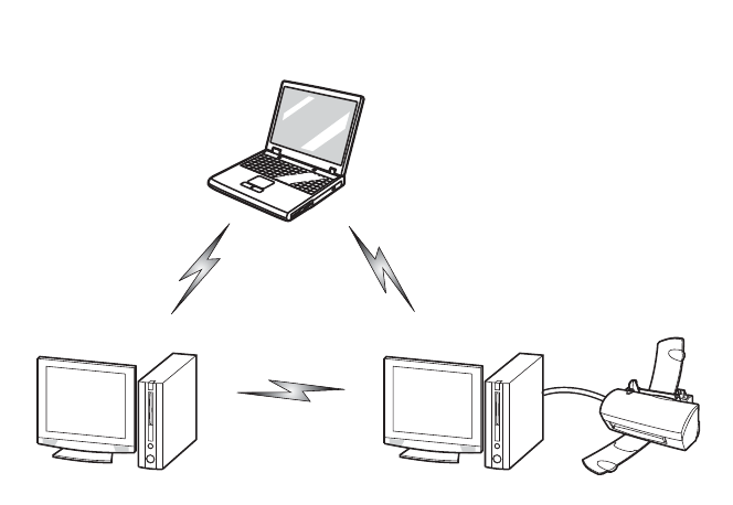
50
Wireless LAN Modes Using this Device
Ad Hoc Mode
"Ad Hoc Mode" refers to a wireless network architecture where
wireless network connectivity between multiple computers is
established without a central wireless network device, typically
known as Access Point(s). Connectivity is accomplished using only
client devices in a peer-to-peer fashion. That is why Ad Hoc
networks are also known as peer-to-peer networks. Ad Hoc
networks are an easy and inexpensive method for establishing
network connectivity between multiple computers. Ad Hoc mode
requires that the SSID, network authentication, and encryption key
settings are identically configured on all computers in the Ad Hoc
network.
Ad Hoc Mode Network
Appendix -T734.fm Page 50 Saturday, September 21, 2013 1:38 PM
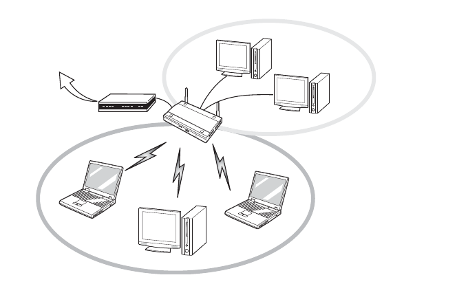
51
Access Point (Infrastructure) Mode
Infrastructure mode refers to a wireless network architecture in
which devices communicate with wireless or wired network devices
by communicating through an Access Point. In infrastructure mode,
wireless devices can communicate with each other or with a wired
network. Corporate wireless networks operate in infrastructure
mode because they require access to the WLAN in order to access
services, devices, and computers (e.g., file servers, printers,
databases).
Access Point (Infrastructure) Mode Network
ADSL modem,
cable modem,
or similar
Internet Wired LAN
Access Point*
Wireless LAN *An optional hub for a wired
LAN may be required depending
upon the type of access point used.
Appendix -T734.fm Page 51 Saturday, September 21, 2013 1:38 PM
52
How to Handle This Device
The WLAN device is an optional device that may come pre-installed
in your mobile computer. Under normal circumstances, it should not
be necessary for you to remove or re-install it. The Operating System
that your mobile computer comes with has been pre-configured to
support the WLAN device.
• Integrated Intel Centrino wireless LAN devices support
IEEE802.11a, IEEE802.11b, IEEE802.11g, and IEEE802.11n.
• The WLAN device operates in the 2.4 GHz ISM band and the 5
GHz lower, middle, and upper UNII bands.
• Microwave ovens may interfere with the operation of WLAN
devices since they operate in the same 2.4 GHz frequency
range as IEEE802.11b/g/n devices. Interference by
microwaves does not occur with IEEE802.11a radio which
operates in the 5 GHz RF band.
• Wireless devices that transmit in the 2.4 GHz range may
interfere with operation of WLAN devices in IEEE802.11b/g/n
modes. Symptoms of interference include reduced
throughput, intermittent disconnects, and many frame
errors. It is HIGHLY recommended that these interfering
devices be powered off to ensure proper operation of the
WLAN device.
Deactivating/Disconnecting the WLAN Device
Disconnecting the WLAN device may be desired in certain
circumstances (to extend battery life) or where certain
environments require it (i.e. hospitals, clinics, airplanes, etc.). The
WLAN device can be deactivated by using the Wireless Device On/Off
Switch, and it can be disconnected in Windows using the WLAN icon
in the system tray (Note that disconnecting via the icon in the
system tray does not turn off the radio; it continues to transmit and
receive even though it’s not connected.)
Appendix -T734.fm Page 52 Saturday, September 21, 2013 1:38 PM
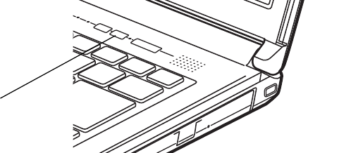
53
Deactivation Using the Wireless Device On/Off Switch
The WLAN device can be deactivated quickly and efficiently by
toggling the Wireless Device On/Off Switch to the Off position.
The
Wireless Device On/Off switch has no effect on non-Wireless LAN
models.
Figure 3. Wireless Device On/Off Switch Location
Disconnection Using the Icon in the Taskbar
Note that disconnecting via the icon in the system tray does not turn
off the radio; it continues to transmit and receive even though it’s
not connected.
1 Right-click the WLAN icon in the taskbar at the bottom right of
your screen.
2 Choose Disconnect from a network.
Activating the WLAN Device
Activation of the WLAN device can be accomplished using the same
methods as the deactivation process
• Using the Wireless Device On/Off Switch
• In Windows, by right-clicking the WLAN icon then clicking
“Connect to a network”
WLAN Switch
Appendix -T734.fm Page 53 Saturday, September 21, 2013 1:38 PM
54
Configuring the Wireless LAN
The optional WLAN device can be configured to establish wireless
network connectivity using the software that is built into Windows.
Support for most industry standard security solutions is contained in
this software.
Pre-defined parameters will be required for this procedure. Please
consult with your network administrator for these parameters:
Configuring the WLAN Using Windows
The WLAN device can be configured to establish wireless network
connectivity using the software that is built into Windows Vista.
Support for most industry standard security solutions is contained in
this software.
Pre-defined parameters are required for this procedure. Consult
your network administrator for these parameters:
1 From the Modern Start screen, press [Windows]+[X], then select
Control Panel from the menu.
2 If the Control Panel is not in Classic View, select Classic View from
the left panel. Double-click the Network and Sharing Center
icon.
3 Select "Setup a new connection or network".
4 Depending upon what type of connection you would like to
make, make a selection. For an infrastructure network, select
“Manually connect to a wireless network”.
5 Enter the required information. It may be necessary to consult
with your network administrator for some of the information.
6 In the event you require assistance, go to the Network and
Sharing Center window (Control Panel > Network and Sharing
Center), and type in relevant keywords in the Search box.
Connection to the network
After you have configured your computer, you can connect to an
active network by performing the following steps:
Appendix -T734.fm Page 54 Saturday, September 21, 2013 1:38 PM

55
1 Click on the WLAN icon in the system tray.
2 Select “Connect to a network”.
3 Select a network from the list that appears, and click the
[Connect] button.
Troubleshooting the WLAN
Causes and countermeasures for troubles you may encounter while
using your wireless LAN are described in the following table.
Problem Possible Cause Possible Solution
Unavailable
network
connection
Incorrect network
name (SSID) or
network key
Ad hoc connection: verify that the network
names (SSID’s) and network keys (WEP) of
all computers to be connected have been
configured correctly. SSID’s and WEP key
values must be identical on each machine.
Access Point (Infrastructure) connection:
set the network name (SSID) and network
key to the same values as those of the
access point.
Set the Network Authentication value
identically to that of the Access Point.
Please consult your network administrator
for this value, if necessary.
Weak received
signal strength
and/or link
quality
Ad hoc connection: Retry connection after
shortening the distance to the destination
computer or removing any obstacles for
better sight.
Access Point (Infrastructure) connection:
Retry connection after shortening the
distance to the access point or removing
any obstacles for better sight.
Appendix -T734.fm Page 55 Saturday, September 21, 2013 1:38 PM

56
Unavailable
network
connection
(continued)
The WLAN device
was deactivated
or is disabled
Check if the wireless switch is turned On.
Go to Start > Control Panel, and double-
click on Windows Mobility Center. If the
wireless network is off, click the [Turn
wireless on] button.
The computer to
be connected is
turned off
Check if the computer to be connected is
turned ON.
Incorrectly
configured
network settings
Recheck the configuration of your network
settings.
RF interference
from Access
Points or other
wireless
networks
The use of identical or overlapping RF
channels can cause interference with the
operation of the WLAN device. Change the
channel of your Access Point to a channel
that does not overlap with the interfering
device.
Wireless network
authentication
has failed
Re-check your Network Authentication,
Encryption, and Security settings.
Incorrectly configured security settings
such as an incorrectly typed WEP key, a
mis-configured LEAP username, or an
incorrectly chosen authentication method
will cause the LAN device to associate but
not authenticate to the wireless network.
Incorrect IP
address
configuration
This only applies to networks using static
IP addresses. Please contact your network
administrator for the correct settings.
Problem Possible Cause Possible Solution
Appendix -T734.fm Page 56 Saturday, September 21, 2013 1:38 PM

57
WLAN Specifications
Specifications
* “Wi-Fi based” indicates that the interconnectivity test of the organization which guarantees
the interconnectivity of wireless LAN (Wi-Fi Alliance) has been passed.
** The communication ranges shown above will increase or decrease depending on factors
such as number of walls, reflective material, or interference from external RF sources.
*** Encryption with network key (WEP) is performed using the above number of bits, however,
users can set 40 bits/ 104 bits after subtracting the fixed length of 24 bits.
**** Depending on practical environments, the allowable number of computers to be
connected may be decreased.
Item Specification
Type of network Integrated Dual-Band Wireless-N 7260 device conforms to IEEE
802.11a, 802.11b/g, and 802.11n, Wi-Fi based*.
Transfer rate (Automatic switching) IEEE802.11 a and g: 54 Mbps max. data
rate; IEEE802.11n: 300 Mbps max. data rate
Active frequency • 802.11n: 2.4 GHz or 5 GHz
• 802.11b/g: 2400~2473 MHz
• 802.11a: 4900 ~ 5850 MHz
Typical operating
distances**
• 802.11a: 40 ft. (12 m) @ 54 Mbps; 300 ft. (91 m) @ 6 Mbps
• 802.11b: 100 ft. (30 m) @ 11 Mbps; 300 ft. (91 m) @ 1 Mbps
• 802.11g: 100 ft. (30 m) @ 54 Mbps; 300 ft. (91 m) @ 1 Mbps
• 802.11n: Estimated double the operating distance of 802.11g
and 802.11a in their respective frequencies.
Number of channels • 802.11a: 8 independent channels
• 802.11b/g: 11 channels, 3 non-overlapping channels
• 802.11n: Channel bonding takes two of the non-overlapping
20MHz channels and combines it into one 40MHz channel. It
is actually 12 non-overlapping channels with channel bonding
and 24 without. Also, it is 1 non-overlapping channel in
2.4GHz when channel bonding is used
Security Encryption Types - WEP, TKIP, AES***, WPA 1.0 and WPA 2.0
compliant
Encryption Key lengths Supported: 64 bits and 128 bits
Maximum recommended
number of computers to be
connected over wireless LAN
(during ad hoc connection)
10 units or less ****
Appendix -T734.fm Page 57 Saturday, September 21, 2013 1:38 PM

58
Using the Bluetooth Device
Bluetooth is integrated into the Wireless LAN module. The Blue-
tooth capabilities are Bluetooth Basic, EDR and Bluetooth Low Energy
(BT v4.0) operational modes.
What is Bluetooth
Bluetooth technology is designed as a short-range wireless link
between mobile devices, such as laptop computers, phones, print-
ers, and cameras. Bluetooth technology is used to create Personal
Area Networks (PANs) between devices in short-range of each
other.
Where to Find Information About Bluetooth
For additional information about Bluetooth Technology, visit the
Bluetooth Web site at: www.bluetooth.com.
TO ENABLE OR DISABLE EITHER THE WIRELESS LAN OR BLUETOOTH
DEVICES INDIVIDUALLY, PERFORM THE FOLLOWING STEPS:
> TURN ON THE WLAN/BLUETOOTH SWITCH.
> GO TO THE MODERN START SCREEN -> CHARMS -> SETTINGS -> CHANGE
PC SETTINGS -> WIRELESS.
> UNDER WIRELESS->WIRELESS DEVICES, CLICK ON "BLUETOOTH" SWITCH
TO TURN IT ON.
Appendix -T734.fm Page 58 Sunday, September 29, 2013 12:35 PM
59
FCC Radiation Exposure Statement
This equipment complies with FCC radiation exposure limits set
forth for an uncontrolled environment. The Bluetooth antenna is
located on the front edge of the right palm rest and is exempt from
minimum distance criteria due to its low power.
The transmitters in this device must not be co-located or operated
in conjunction with any other antenna or transmitter.
Canadian Notice
To prevent radio interference to the licensed service, this device is
intended to be operated indoors and away from windows to provide
maximum shielding. Equipment (or its transmit antenna) that is
installed outdoors is subject to licensing.
Warranty
Users are not authorized to modify this product. Any modifications
invalidate the warranty.
This equipment may not be modified, altered, or changed in any
way without signed written permission from Fujitsu. Unauthorized
modification will void the equipment authorization from the FCC
and Industry Canada and the warranty.
Appendix -T734.fm Page 59 Sunday, September 29, 2013 12:35 PM