Fujitsu Client Computing WL0011 AR5B6 XB62 ATHEROS WLAN IN FUJITSU NOTEBOOKS User Manual USERS MANUAL 2
Fujitsu Limited AR5B6 XB62 ATHEROS WLAN IN FUJITSU NOTEBOOKS USERS MANUAL 2
UserManual.wiki
>
Fujitsu Client Computing
>
WL0011 User Manual
>
USERS MANUAL 2
Contents
1.
USERS MANUAL 1
2.
USERS MANUAL 2
USERS MANUAL 2
Navigation menu
Upload a User Manual
Namespaces
Wiki Guide
HTML
PDF
Info
Views
User Manual
Discussion / Help
Navigation


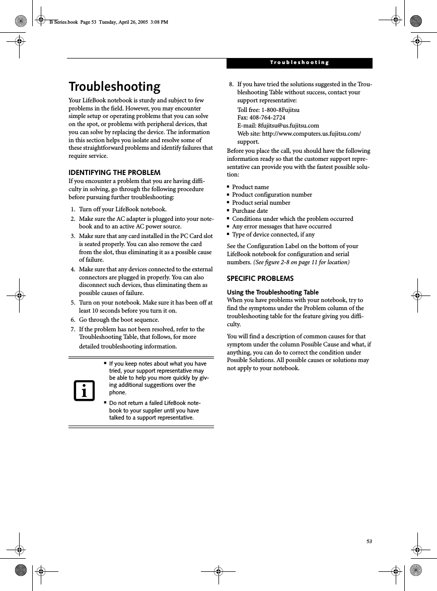
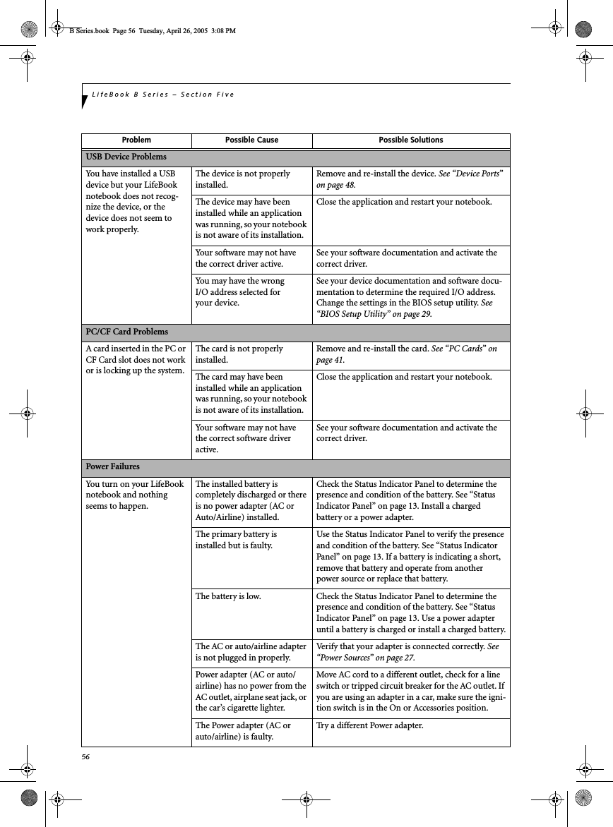
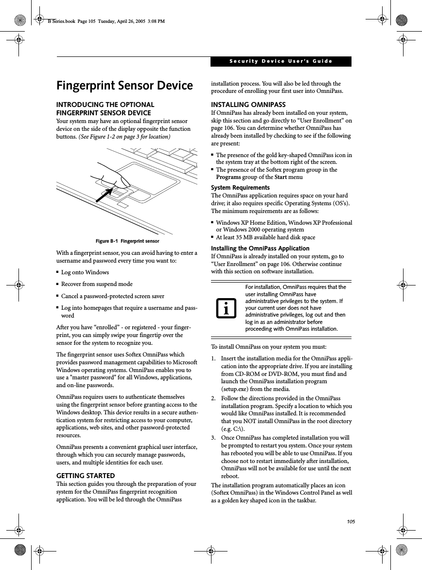
![54LifeBook B Series – Section FiveTROUBLESHOOTING TABLEProblem PageAudio Problems . . . . . . . . . . . . . . . . . . . . . . . . . . page 54Docking Problems . . . . . . . . . . . . . . . . . . . . . . . . page 54Floppy Disk Drive Problems . . . . . . . . . . . . . . . . page 54Hard Drive Problems . . . . . . . . . . . . . . . . . . . . . . page 54Keyboard or Mouse Problems. . . . . . . . . . . . . . . page 55Memory Problems . . . . . . . . . . . . . . . . . . . . . . . . page 55Problem PageModem Problems. . . . . . . . . . . . . . . . . . . . . . . . . page 55USB Device Problems . . . . . . . . . . . . . . . . . . . . . page 56PC Card Problems . . . . . . . . . . . . . . . . . . . . . . . . page 56Power Failures . . . . . . . . . . . . . . . . . . . . . . . . . . . page 56Shutdown and Startup Problems . . . . . . . . . . . . page 58Video Problems . . . . . . . . . . . . . . . . . . . . . . . . . . page 58Miscellaneous Problems . . . . . . . . . . . . . . . . . . . page 60Problem Possible Cause Possible SolutionsAudio ProblemsThere is no sound coming from the built-in speakers.The volume is turned too low. Adjust the volume control on your notebook.The software volume control is set too low.Adjust the sound volume control settings in your software, operating system and applications.Headphones are plugged into your notebook.Plugging in headphones disables the built-in speakers, remove the headphones.BIOS audio settingsare incorrect.Set the BIOS setup utility to the default values within the Advanced/Miscellaneous Configurations menu. See “BIOS Setup Utility” on page 29.Software driver is not config-ured correctly.Refer to your application and operating system documentation for help.Sound could have been muted with function keys.Press [F3] while holding the [Fn] key to toggle the sound on and off.Port Replicator ProblemsLifeBook notebook does not turn on when installed in optional Port ReplicatorPort Replicator AC adapter is not plugged in. Provide power to the Port Replicator.Notebook is not properly seated in the Port Replicator.Remove and re-dock your notebook.Floppy Disk Drive ProblemsYou cannot access your floppy disk.You tried to write to a write protected floppy disk.Eject the floppy disk and set it to write enable. See “Preparing a Disk for Use” on page 39.Floppy disk is not loaded correctly.Eject floppy disk, check orientation and re-insert. See “Ejecting a Disk” on page 39.The floppy disk drive may not be properly installed.Remove and re-install your floppy disk drive. Security is set to protect access to floppy disk data.Verify your password and security settings.The USB floppy disk drive is not selected in the BIOS.Verify that USB Support is enabled in the BIOS Advanced menu. See “BIOS Setup Utility” on page 29.Hard Drive ProblemsYou cannot access your hard drive.The setup utility is incorrectly set for your hard drive.Revise BIOS settings to set both Primary Masterand Primary Slave correctly. See “BIOS Setup Utility” on page 29.B Series.book Page 54 Tuesday, April 26, 2005 3:08 PM](https://usermanual.wiki/Fujitsu-Client-Computing/WL0011.USERS-MANUAL-2/User-Guide-650347-Page-5.png)
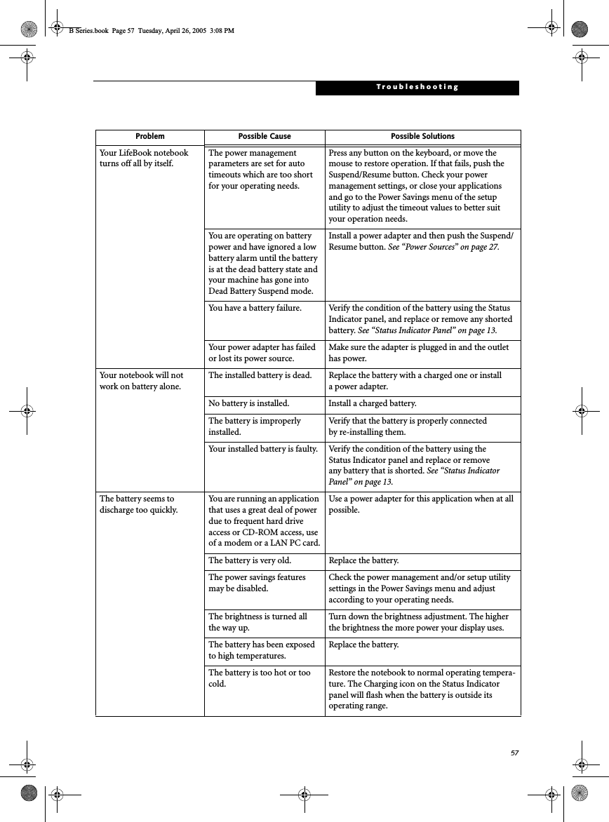
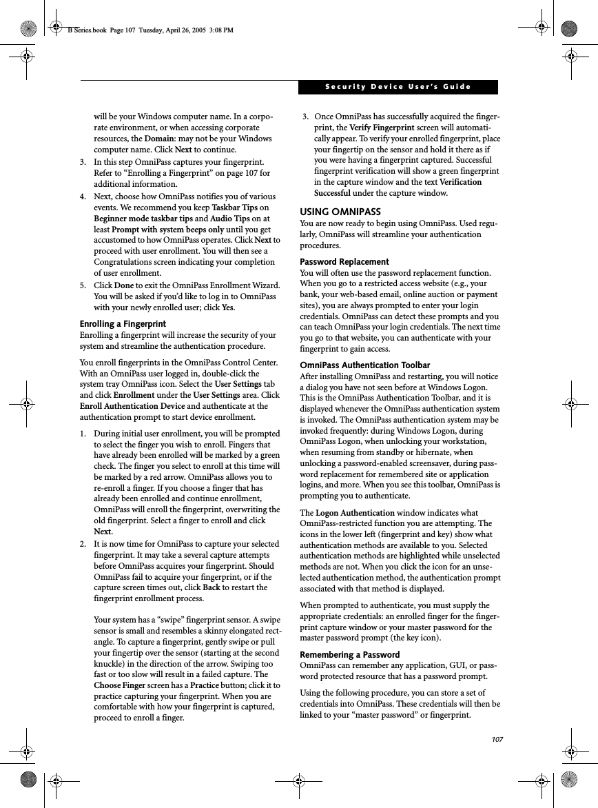
![55TroubleshootingYou cannot access your hard drive.(continued)The wrong drive designator was used by an application when a bootable CD-ROM was used to start the notebook.Verify drive designator used by application is inuse by the operating system. When the operating system is booted from a CD, drive designationsare automatically adjusted. Security is set so your oper-ating system cannot be started without a password.Verify your password and security settings.Keyboard or Mouse ProblemsThe built-in keyboard does not seem to work.The notebook has gone into Standby mode.Push the Suspend/Resume button.Your application has locked out your keyboard.Try to use your integrated pointing device to restart your system. If this fails, turn your notebook off, wait 10 seconds or more, and then turn it back on.You have installed an external keyboard or mouse, and it does not seem to work.Your external device is not properly installed.Re-install your device. See “Device Ports” on page 48.Your operating system soft-ware is not setup with the correct software driver for that device.Check your device and operating system docu-mentation and activate the proper driver.You have connected an external keyboard or a mouse and it seems to be locking up the system.Your operating system soft-ware is not set up with the correct software driver for that device.Check your device and operating systemdocumentation and activate the proper driver.Your system has crashed. Try to restart your notebook. If that fails, turn off power, wait at least 10 seconds, then re-apply power. Memory ProblemsYour Power On screen, or Main menu of the BIOS setup utility information, does not show the correct amount of installed memory.Your memory upgrade module is not properly installed.Turn off your notebook. Remove and re-install your memory upgrade module. See “Memory Upgrade Module” on page 44.You have a memory failure. Check for Power On Self Test (POST) messages. If you are unclear on the message, contact your support representative. See “Power On Self Test Messages” on page 61.Modem ProblemsMessages about modem operation.Messages about modem operation are generated by whichever modem application is in use.See your application software documentation for additional information.The modem driver has not been properly initialized.Go to Start -> Control Panel -> System. Select the Hardware tab and click the [Device Manager] button. Click on Modems and verify that your modem is listed.Problem Possible Cause Possible SolutionsB Series.book Page 55 Tuesday, April 26, 2005 3:08 PM](https://usermanual.wiki/Fujitsu-Client-Computing/WL0011.USERS-MANUAL-2/User-Guide-650347-Page-6.png)
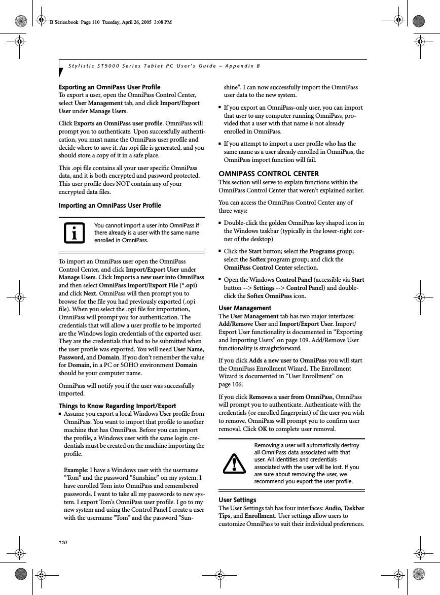
![58LifeBook B Series – Section FiveShutdown and Startup ProblemsThe Suspend/Resume button does not work.The Suspend/Resume button is disabled from the Advanced submenu of the Power menu of the setup utility. Enable the button from the setup utility.You did not hold the button in long enough.Hold the button longer. This may need to be a few seconds if your application is preventing the CPU from checking for button pushes.There may be a conflict with the application software.Close all applications and try the button again.The system powers up, and displays power on informa-tion, but fails to load the operating system.The boot sequence settings of the setup utility are not compatible with your configuration.Set the operating source by pressing the [F2] key while the Fujitsu logo is on screen and enter the setup utility and adjust the source settings from the Boot menu. See “BIOS Setup Utility” on page 29.You have a secured system requiring a password to load your operating system.Make sure you have the right password. Enter the setup utility and verify the Security settings and modify them as accordingly. See “BIOS Setup Utility” on page 29.An error message is displayed on the screen during the LifeBook note-book boot sequence.Power On Self Test (POST) has detected a problem.See the Power On Self Test (POST) messages to determine the meaning of the problem. Not all messages are errors; some are simply status indica-tors. See “Power On Self Test Messages” on page 61.Your system display won’t turn on when the system is turned on or when the system has resumed.The system may be password-protected.Check the status indicator panel to verify that the Security icon is blinking. If it is blinking, enter your password.Your notebook appears to change setup parameters when you start it.BIOS setup changes were not saved when you exited the BIOS setup utility, returning it to previous settings.Make sure you select Save Changes And Exit when exiting the BIOS setup utility.The BIOS CMOS back-up battery has failed.Contact your support representative for repairs. This is not a user serviceable part but has a normal life of 3 to 5 years.Video ProblemsThe built-in display is blank when you turn on your notebook.The optional Port Replicator is attached, an external monitor is plugged in, and the note-book is set for an external monitor only.Pressing [F10] while holding down the [Fn] key allows you to change your selection of where tosend your display video. Each time you press the combination of keys you will step to the nextchoice. The choices, in order are: built-in display only, external monitor only, both built-in display and external monitor.The angle of the display and the brightness settings are not adequate for your lighting conditions.Move the display and the brightness control until you have adequate visibility.Problem Possible Cause Possible SolutionsB Series.book Page 58 Tuesday, April 26, 2005 3:08 PM](https://usermanual.wiki/Fujitsu-Client-Computing/WL0011.USERS-MANUAL-2/User-Guide-650347-Page-9.png)
![59TroubleshootingThe built-in display is blank when you turn on your notebook.(continued)The power management timeouts may be set for very short intervals and you failed to notice the display come onand go off again.Press any button the keyboard, or move the mouse to restore operation. If that fails, push the Suspend/Resume button. (The display may be shut off by Standy mode, Auto Suspend or Video Timeout)The notebook turned on with a series of beeps and your display is blank.Power On Self Test (POST) has detected a failure that does not allow the display to operate. Contact your support representative.Your system display won’t turn on when the system is turned on or when the system has resumed.The system may be password-protected.Check the status indicator panel to verify that the Security icon is blinking. If it is blinking, enter your password.The display goes blank by itself after you have been using it.The notebook has gone into Video Timeout, Standby Mode, or Hibernate Mode because you have not used it for a period of time.Press any button on the keyboard, or move the mouse to restore operation. If that fails, push the Suspend/Resume button. Check your power management settings, or close your applications and go to the Power Savings menu of the setup utility to adjust the timeout values to better suit your opera-tion needs. See “BIOS Setup Utility” on page 29.The power management time-outs may be set for very short intervals and you failed to notice the display come onand go off again.Press any button on the keyboard, or move the mouse to restore operation. If that fails, push the Suspend/Resume button. (The display may be shut off by Standby Mode, Auto Suspend or Video Timeout)The display does not close. A foreign object, such as a paper clip, is stuck between the display and the keyboard.Remove all foreign objects from the keyboard.The display has bright or dark spots.If the spots are very tiny and few in number, this is normal for a large LCD display.This is normal; do nothing.If the spots are numerous or large enough to interfere with your operation needs.Display is faulty; contact your support representa-tive.The application display uses only a portion of your screen and is surrounded by a dark frame.You are running an application that does not support 800 x 600/1024 x 768 pixel resolution display and display compres-sion is enabled.Display compression gives a clearer but smaller display for applications that do not support 800 x 600/1024 x 768 pixel resolution. You can fill the screen but have less resolution by changing your display compression setting, (See the Video Features submenu, located within the Advanced menu of the BIOS. See “BIOS Setup Utility” on page 29.The Display is dark when on battery power.The BatteryAid default is seton low brightness toconserve power.Press [Fn] + [F7] to increase brightness or double-click on BatteryAid battery gauge and adjust Power Control under battery settings.Problem Possible Cause Possible SolutionsB Series.book Page 59 Tuesday, April 26, 2005 3:08 PM](https://usermanual.wiki/Fujitsu-Client-Computing/WL0011.USERS-MANUAL-2/User-Guide-650347-Page-10.png)
![60LifeBook B Series – Section FiveYou have connected an external monitor and it does not display any information.Your BIOS setup is not set to enable your external monitor.Try toggling the video destination by pressing [Fn] and [F10] together, or check your BIOS setup and enable your external monitor. (See the Video Features submenu, located within the Advanced Menu of the BIOS. See “BIOS Setup Utility” on page 29.Your external monitor is not properly installed. Reinstall your device. See “External Monitor Port” on page 49.Your operating system soft-ware is not setup with the correct software driver forthat device. Check your device and operating systemdocumentation and activate the proper driver.You have connected an external monitor and it does not come on.Your external monitor is not compatible with your notebook.See your monitor documentation and theExternal Monitor Support portions of theSpecifications section. See “Specifications” on page 73.Miscellaneous ProblemsAn error message is displayed on the screen during the operation ofan application.Application software often has its own set of error message displays. See your application manual and help displays screens for more information. Not all messages are errors some may simply be status.Problem Possible Cause Possible SolutionsB Series.book Page 60 Tuesday, April 26, 2005 3:08 PM](https://usermanual.wiki/Fujitsu-Client-Computing/WL0011.USERS-MANUAL-2/User-Guide-650347-Page-11.png)

![62LifeBook B Series – Section Five*Parity Check 1 nnnn Parity error found in the system bus. BIOS attempts to locate the address and display it on the screen. If it cannot locate the address, it displays "????". This is apotentially data destroying failure. Contact yoursupport representative.*Parity Check 2 nnnn Parity error found in the I/O bus. BIOS attempts to locate the address and display it on the screen. If it cannot locate the address, it displays "????". This is apotentially data destroying failure. Contact yoursupport representative.*Press <F1> to resume, <F2> to SETUP Displayed after any recoverable error message. Pressthe [F1] key to continue the boot process or the [F2]key to enter Setup and change any settings.*Previous boot incomplete – Default configuration used Previous Power On Self Test did not complete success-fully. The Power On Self Test will load default values and offer to run Setup. If the previous failure was caused by incorrect values and they are not corrected, the next boot will likely fail also. If using the default settings does not allow you to complete a successful boot sequence, you should turn off the power and contact your support representative.*Real time clock error Real-time clock fails BIOS test. May require board repair. Contact your support representative.*Shadow RAM Failed at offset: nnnn Shadow RAM failed at offset nnnn of the 64k block at which the error was detected. You are risking data corruption if you continue. Contact your support repre-sentative.nnnn Shadow RAM Passed Where nnnn is the amount of shadow RAM in kilobytes successfully tested.*System battery is dead – Replace and run SETUP The BIOS CMOS RAM memory hold up battery is dead. This is part of your BIOS and is a board mounted battery which requires a support representative to change. You can continue operating but you will have to use setup utility default values or reconfigure your setup utility every time you turn off your notebook. This battery has an expected life of 2 to 3 years.System BIOS shadowed System BIOS copied to shadow RAM.*System CMOS checksum bad – run SETUP BIOS CMOS RAM has been corrupted or modified incorrectly, perhaps by an application program that changes data stored in BIOS memory. Run Setup and reconfigure the system.*System RAM Failed at offset: nnnn System memory failed at offset nnnn of in the 64k block at which the error was detected. This means that there is a fault in your built-in memory. If you continue to operate, you risk corrupting your data. Contact your support representative for repairs.nnnn System RAM PassedWhere nnnn is the amount of system memory inkilobytes successfully tested.*System timer error The timer test failed. The main clock that operates the computer is faulty. Requires repair of system board. Contact your support representative for repairs.UMB upper limit segment address: nnnn Displays the address of the upper limit of Upper Memory Blocks, indicating released segments of the BIOS memory which may be reclaimed by a virtual memory manager.Video BIOS shadowed Video BIOS successfully copied to shadow RAM.MODEM RESULT CODESThe operating system and application software that is factory installed detects the modem characteristics and provides the necessary command strings to operate the modem. The internal modem operation is controlled by generic AT commands from the operating system and application software. The standard long form result codes may, in some cases, be displayed on your screen to keep you informed of the actions of your modem. The operating system and application software may suppress display of the result codes. Examples of result codes are:■OK■NO CARRIER■NO DIALTONE■CONNECT 53000 (Connection complete at 53,000 bps.)■ERROR■FAX■RING (This means an incoming call.)■BUSY■NO ANSWERWhen using the internal modem with applications that are not factory installed refer to the application documentation.B Series.book Page 62 Tuesday, April 26, 2005 3:08 PM](https://usermanual.wiki/Fujitsu-Client-Computing/WL0011.USERS-MANUAL-2/User-Guide-650347-Page-13.png)
![63TroubleshootingRestoring Your Pre-installed SoftwareThe Drivers and Applications Restore (DAR) DVD contains sets of device drivers and Fujitsu utilities (in specific directories) that are unique to your computer configuration for use as documented below.Re-Installing Individual Drivers and Applications The Drivers and Applications CD can be used to selectively re-install drivers and/or applications that may have been un-installed or corrupted. To re-install drivers and/or applications:1. Boot up the system and insert the DAR CD after Windows has started. A Fujitsu Installer screen is displayed after the CD is inserted.2. After reading the License Agreement, click [I agree].3. A window will appear containing a list of applica-tions, drivers, and utilities that you can install from the Drivers and Applications CD.4. In the list, check off all the components you want to install. If you want to install all components, click [Select All]. Clicking [Select All] will select all of the blue-coded components; you must select grey and green components separately.5. Once you have selected the components you wish to install, click [Install Selected Subsystems]; the components will be installed.6. After the components are installed, click [OK], then click [Yes] when asked if you want to reboot the system. RESTORING THE FACTORY IMAGEThe Restore Disc that came with your system contains two utilities:■The Recovery utility allows you to restore the original contents of the C: drive.■The Hard Disk Data Delete utility on this disc is used to delete all data on your hard disk and prevent it from being reused. Do not use the Hard Disk Data Delete utility unless you are absolutely certain that you want to erase your entire hard disk, including all partitions.BOOT Priority ChangeBefore restoring an image, you must first verify that your system is set up to boot from the DVD drive. To verify/change the boot-up priority (rather than booting-up from the hard drive or an external floppy disk drive), perform the following steps:1. Start your system and press the [F2] key when the Fujitsu logo appears. You will enter the BIOS Setup Utility.2. Using the arrow keys, go to the Boot menu.3. Arrow down to the Boot Device Priority submenu. Press [Enter].4. If “Optical Media Drive” or “CD-ROM Drive” is not at the top of the list, arrow down to the drive in the list, and press the space bar (or the + key) to move it to the top of the list. (The system attempts to boot from the devices in the order in which they are listed.). Note that the BIOS for some systems will indicate “CD-ROM Drive”, even when a DVD drive is connected.5. If you have an external DVD drive connected, proceed to the next step; otherwise, proceed to step 7.6. If you have an external DVD drive connected:In order to install applications and/or drivers from the DAR DVD, you will need to connect an external DVD drive to your system.If you have access to the internet, visit the Fujitsu Support web site at http://www.computers.us.fujitsu.com/support to check for the most current information, drivers and hints on how to perform recovery and system updates.There may be certain free third-party applications pre-installed on your system that are not on the DAR CD. The latest versions of the applications can be downloaded from the third-party’s website.The components listed are color-coded in terms of their install status. Blue indicates that the component can be installed. Green indicates that the component needs to be installed separately. Grey indicates a component that is already installed; grey items can be reinstalled, but prior to installation you will receive a reminder that the component is already installed. • The use of this disc requires that you have a device capable of reading DVDs attached to your system. If you do not have a built-in DVD player, you will need to attach an external player. For more information on available external devices, visit our Web site at: us.fujitsu.com/computers.• This disc can only be used with the system with which it was purchased.B Series.book Page 63 Tuesday, April 26, 2005 3:08 PM](https://usermanual.wiki/Fujitsu-Client-Computing/WL0011.USERS-MANUAL-2/User-Guide-650347-Page-14.png)
![64LifeBook B Series – Section Five• Select the Advanced menu in the BIOS window.• Scroll down to the USB Features submenu and press the Enter key to open it.• If Legacy USB Support is disabled, press the space bar to enable it.• Scroll down to SCSI SubClass Support and press the space bar to enable it. 7. Press [F10], then click on [Yes] to exit the BIOS Setup Utility and return to the boot process.After you have changed the boot priority, you can restore a backup image when you are booting up.Procedure1. Turn on the power to your system.2. Ensure that you have a device that can read DVDs either installed in your system or attached exter-nally to it.3. Insert the Restore Disc into the drive tray.4. Reboot your system.5. After the system reboots, follow the instructions that appear to either restore your system image or erase all data from your hard disk.AUTOMATICALLY DOWNLOADING DRIVER UPDATESYour system has a convenient tool called the Fujitsu Driver Update (FDU) utility. With FDU, you can choose to automatically or manually go to the Fujitsu site to check for new updates for your system.The FDU icon should appear in the system tray at the bottom right of your screen (roll the cursor over the icons to find the correct one). If the FDU icon does not appear in the system tray, it can be started by going to [Start] -> All Programs, and clicking on Fujitsu Driver Update; this will create the icon automatically.To invoke the FDU menu, you can either right-click on the FDU icon or hold the pen on the icon for a couple of seconds until the menu appears. The menu contains the following items:■Check for updates nowAllows for manual driver update search. The first time it is used, you are prompted to agree to a user agreement. After clicking on the icon, the FDU auto-matically connects with the Fujitsu site to check for updates and downloads them. While downloading, the icon has a red bar through it, indicating that it cannot be used while the download is in process. When the update is complete, a message appears informing you of the fact.■Enable Automatic Update NotificationsAutomatically searches for new updates on a regular basis (approximately every 3 days).■Show update historyBrings up a screen that displays a history of updates that have been made via the FDU.■About Fujitsu Driver UpdateDisplays the FDU version number and copyright information■Fujitsu Driver Update ReadmeDisplays the FDU readme.B Series.book Page 64 Tuesday, April 26, 2005 3:08 PM](https://usermanual.wiki/Fujitsu-Client-Computing/WL0011.USERS-MANUAL-2/User-Guide-650347-Page-15.png)


![89WIreless LAN User’s GuideFCC REGULATORY INFORMATIONPlease note the following regulatory information related tothe optional wireless LAN device.Regulatory Notes and StatementsWireless LAN, Health and Authorization for useRadio frequency electromagnetic energy is emitted fromWireless LAN devices. The energy levels of these emissions,however, are far much less than the electromagnetic energyemissions from wireless devices such as mobile phones.Wireless LAN devices are safe for use by consumers becausethey operate within the guidelines found in radio frequencysafety standards and recommendations. The use of WirelessLAN devices may be restricted in some situations or envi-ronments, such as:On board an airplane, orIn an explosive environment, orIn situations where the interference risk to other devicesor services is perceived or identified as harmful.In cases in which the policy regarding use of Wireless LANdevices in specific environments is not clear (e.g., airports,hospitals, chemical/oil/gas industrial plants, private build-ings), obtain authorization to use these devices prior tooperating the equipment.Regulatory Information/DisclaimersInstallation and use of this Wireless LAN device must be instrict accordance with the instructions included in the userdocumentation provided with the product. Any changes ormodifications made to this device that are not expresslyapproved by the manufacturer may void the user’s authorityto operate the equipment. The manufacturer is not respon-sible for any radio or television interference caused byunauthorized modification of this device, or the substitu-tion or attachment of connecting cables and equipmentother than those specified by the manufacturer. It is theresponsibility of the user to correct any interference causedby such unauthorized modification, substitution or attach-ment. The manufacturer and its authorized resellers ordistributors will assume no liability for any damage orviolation of government regulations arising from failure tocomply with these guidelines.This device must not be co-located or operating in conjunc-tion with any other antenna or transmitter.For operation within 5.15~5.25 GHz frequency range, it isrestricted to indoor environments, and the antenna of thedevice must be integral.Federal Communications Commission statementThis device complies with Part 15 of FCC Rules.Operation is subject to the following two conditions: (1)This device may not cause interference, and, (2) This devicemust accept any interference, including interference thatmay cause undesired operation of this device.FCC Interference StatementThis equipment has been tested and found to comply withthe limits for a Class B digital device, pursuant to Part 15 ofthe FCC Rules. These limits are designed to provide reason-able protection against harmful interference in a residentialinstallation. This equipment generates, uses, and canradiate radio frequency energy. If not installed and used inaccordance with the instructions, it may cause harmfulinterference to radio communications. However, there is noguarantee that interference will not occur in a particularinstallation.If this equipment does cause harmful interference to radioor television reception, which can be determined by turningthe equipment off and on, the user is encouraged to try andcorrect the interference by one or more of the followingmeasures:1. Reorient or relocate the receiving antenna.2. Increase the distance between the equipment and thereceiver.3. Connect the equipment to an outlet on a circuitdifferent from the one the receiver is connected to.4. Consult the dealer or an experienced radio/TVtechnician for help.FCC Radio Frequency Exposure statementThis equipment complies with FCC radiation exposurelimits set forth for an uncontrolled environment. Thisequipment should be installed and operated with aminimum distance of 20 centimeters between the WirelessLAN/Bluetooth antenna and your body. The WLANantennas are located on left and right ends of the top edgeof the LCD screen; the Bluetooth antenna is located at rightof the [Back Space] key, above the connector.The transmitters in this device must not be co-located oroperated in conjunction with any other antenna or trans-mitter.Export restrictionsThis product or software contains encryption code whichmay not be exported or transferred from the US or Canadawithout an approved US Department of Commerce exportlicense. This device complies with Part 15 of FCC Rules., aswell as ICES 003 B / NMB 003 B. Operation is subject to thefollowing two conditions: (1) this device may not causeharmful interference, and (2) this device must accept anyinterference received, including interference that may causeundesirable operation. Modifications not expressly autho-rized by Fujitsu Computer Systems Corporation may invali-date the user's right to operate this equipment.Canadian NoticeB Series.book Page 89 Tuesday, April 26, 2005 3:08 PMsideThe device for the band 5150 - 5250 MHz is only for indoor usage toreduce the potential for harmful interference to co-channel mobilesatellite systems.The maximum antenna gain of 6 dBi permitted (for devices in the5250 - 5350 MHz and 5470 - 5725MHz bands) to comply with thee.i.r.p. limit.In addition, users are also cautioned to take note that high powerradars are allocated as primary users (meaning they have priority) of5250 - 5350 MHz and 5650 - 5850 MHz and these radars could causeinterference and/or damage to LE-LAN devices.](https://usermanual.wiki/Fujitsu-Client-Computing/WL0011.USERS-MANUAL-2/User-Guide-650347-Page-40.png)
![92LifeBook T Series Tablet PC - AppendixDeactivation using the Wireless On/Off SwitchThe WLAN device can be deactivated quickly and effi-ciently by toggling the Wireless On/Off Switch to the Offposition. (Figure A-3)The wireless On/Off switch has no effect on non-Wire-less LAN models.The Wireless LAN/Bluetooth On/Off switch has noeffect on systems without wireless devices.Figure A-3. Wireless LAN/Bluetooth SwitchDeactivation using the Intel PROSet SoftwareThe WLAN device can also be deactivated in Windowsusing the Intel PROSet Software. The procedure toaccomplish this:1. Click [Start]-> [All Programs].2. Select Intel ProSet Wireless, then click on IntelProSet Wireless from the menu that appears. TheIntel ProSet Wireless utility will be displayed.3. At the bottom left corner of the window, selectWireless Off from the dropdown list.Deactivation using Atheros Client Utility software1. Click [Start] -> [Program Files] -> [Atheros] ->Atheros Client Utility.2. Choose Action and click Disable Radio.ACTIVATING THE WLAN DEVICEActivation of the WLAN device can be accomplishedusing the same methods as the deactivation processUsing the Wireless On/Off SwitchIn Windows using the Intel PROSet Software orAtheros Software.The Wireless LAN/Bluetooth On/OffSwitch will power off both the optionalwireless LAN and Bluetooth devices at thesame time. To enable or disable either oneof the devices individually, perform thefollowing steps:1. Slide the Wireless LAN/Bluetooth on/off switch to On position.2. In the Control Panel, double-click theFujitsu Radio Control icon.3. In the window that appears, click thebutton associated with Bluetooth and/or Wireless LAN Status to enable or dis-able the individual devices.4. Click [OK].Wireless LAN/BluetoothOn/Off SwitchT Series.book Page 98 Thursday, July 14, 2005 2:24 PM](https://usermanual.wiki/Fujitsu-Client-Computing/WL0011.USERS-MANUAL-2/User-Guide-650347-Page-43.png)
![93WIreless LAN User’s Guide Configuration of the WLAN DeviceThe optional WLAN device can be configured to estab-lish wireless network connectivity using the Atheros Client Utility software. The Atheros Client Utility soft-ware allows for multiple profile setups and supports automatic profile switching. Support for most industry standard security solutions, as well as Cisco Compatible Extensions (CCX), is contained in this software.FLOW OF OPERATIONS1. Activate the WLAN Device (See Activating the WLAN Device on page 92 for more information).2. Configure the Wireless Network Key parameters (See “Configuration Using Atheros Client Utility Software” on page 93 for more information).■Enter the network name (SSID)■Choose the appropriate WLAN architecture (Ad Hoc or Infrastructure)■Choose Authentication method: Open, Shared, WPA, or WPA-PSK■If using static WEP keys, enter static WEP key and choose key index. 3. Configure network settings■TCP/IP settings■Workgroup or Domain settings.CONFIGURATION USING ATHEROS CLIENT UTILITY SOFTWAREThis section explains the procedure to properly configure the WLAN device using the Atheros Client Utility. Pre-defined parameters will be required for this procedure. Please consult with your network adminis-trator for these parameters:Network Name: Also known as the SSIDNetwork Key (WEP): Required if using static WEP keys. Authentication Type: Open, Shared, WPA, or WPA-PSKProcedure1. Activate the WLAN device using either the Wireless On/Off Switch or the Atheros Client Utility2. Click [Start] -> Programs -> Atheros -> Atheros Client Utility.3. Click the Profile Management tab. 4. If this is your first time using this utility, highlight the profile [Default] and Click the [Modify] button, otherwise Click the [New] button. The Profile Management dialog displays. 5. From the General tab, enter a profile name in the Profile Name field. 6. Enter the network SSID, in the SSID1 field. If you wish to create a profile that can connect to up to 3 different wireless networks, SSID's can be entered in the SSID2 and SSID3 fields as well.7. Click the Security tab. 8. The Security tab allows for the configuration of the Security modes listed in the table below. Please select the radio button of the desired security mode. If these settings are not known to you, please consult with your network administrator for the correct settings. 9. Click [OK].10. Click the Advanced tab.11. The Advanced tab allows for the configuration of the options detailed in the table below.Field Name DescriptionWPA/WPA2 Enables the use of Wi-Fi Protected Access. Choosing WPA opens the WPA EAP drop-down menu. If these settings are not known to you, please consult with your network administrator for the correct settings. WPA/WPA2 Passphrase Enables WPA-Pre-Shared Key. Click on the Configure button to enter the WPA Passphrase. If these settings are not known to you, please consult with your network administrator for the correct settings. 802.1x Enables 802.1x security. If these settings are not known to you, please consult with your network administrator for the correct settings. Choosing this option opens the 802.1x EAP type drop-down menu.Pre-Shared Key Enables the use of pre-shared keys that are defined on both the access point and the station. This is where static WEP keys are entered. Click the Configure button to fill in the Define Pre-Shared Keys window.None No securityB Series.book Page 93 Tuesday, April 26, 2005 3:08 PM](https://usermanual.wiki/Fujitsu-Client-Computing/WL0011.USERS-MANUAL-2/User-Guide-650347-Page-44.png)
![94LifeBook B Series Notebook - Appendix A12. Click [OK].13. If the profile you just created does not activate immediately, click the Profile Management tab, highlight the desired Profile, and click Activate.14. Click [OK] to close the Atheros Client Utility.CONNECTION TO THE NETWORKThis section explains connection to the network.If there is an administrator of the network, contact the network administrator for data settings.Setting the networkPerform the “Setting TCP/IP” and “Confirming the computer and work group names” operations required for network connection.Setting TCP/IP1. Click the [Start] button first and then [Control Panel].2. If the Control Panel is in Category view, switch to Classic view by clicking “Switch to Classic View” under Control Panel the left frame. (If you are already in Classic view, “Switch to Category View” will be displayed.) 3. Double-click [Network Connections]. A list of cur-rently installed networks will be displayed.4. Right-click [Wireless Network Connection] in the list, and then click [Properties] in the menu dis-played. The [Wireless Network Connection Proper-ties] window will be displayed.5. Click the [General] tab if it is not already selected.6. Click [Internet Protocol (TCP/IP] and then click [Properties]. The [Internet Protocol (TCP/IP) Properties] window will be displayed.7. Set the IP address as follows:■For ad hoc connection: Select [Use the following IP address:] and then enter data for [IP address] and [Subnet mask]. See page 100 for IP address setting.■For access point (infrastructure) connection: If your network uses DHCP, select [Obtain an IP address automatically] and [Obtain DNS server address automatically]. If your network uses static IP addresses, consult with your network adminis-trator for the correct IP address settings.8. Click the [OK] button. Processing will return to the [Wireless Network Connection Properties] window.9. Click the [OK] button.10. Close the [Network Connection] window. Following this operation, confirm the names of the computer and the workgroup as follows.Confirming the computer and work group names1. Click the [Start] button, then [Control Panel].2. If the Control Panel is in Category view, switch to Classic view by clicking “Switch to Classic View” under Control Panel the left frame. (If you are already in Classic view, “Switch to Category View” will be displayed.) 3. Double-click the [System] icon. The [System Prop-erties] window will be displayed.4. Click the [Computer Name] tab.Field Name DescriptionPower Save ModeOptions are Maximum, Normal, or OffNetwork Type Options are AP (Infrastructure) or Ad Hoc802.11bPreambleSpecifies the preamble setting in 802.11b. The default setting is Short and Long (Access Point mode), which allows both short and long headers in the 802.11b frames. Set to Long Only to override allowingshort frames.Transmit Power LevelSelect the desired transmit power level from the dropdown list.Wireless Mode Specifies 5 GHz 54 Mbps, 2.4 GHz 11 Mbps, or 2.4 GHz 54 Mbps oper-ation in an access point network.Wireless Mode when Starting Ad Hoc NetworkSpecifies 5GHz 54 Mbps, 5 GHz 108 Mbps, or 2.4 GHz 11 Mbps to start an Ad Hoc network if no matching network name is found after scan-ning all available modes.To change the setting of the IP address, you need to be logged in from Windows as an administrator.To modify the computer name and/or the work group name, you need to be logged in from Windows as an administrator.B Series.book Page 94 Tuesday, April 26, 2005 3:08 PM](https://usermanual.wiki/Fujitsu-Client-Computing/WL0011.USERS-MANUAL-2/User-Guide-650347-Page-45.png)
![95WIreless LAN User’s Guide 5. Confirm the settings of [Full computer name:] and [Workgroup:].a. The setting of [Full computer name:] denotes the name for identifying the computer. Any name can be assigned for each personal computer.Enter the desired name in less than 15 ASCII character code format. Identifiability can be enhanced by entering the model number, the user name, and other factors.b. [Workgroup name] is the group name of the network. Enter the desired name in less than 15 ASCII character code format.For ad hoc connection: Assign the same network name to all personal computers existing on the network.For access point (infrastructure) connection: Assign the name of the work group to be accessed.6. Click the [OK] button. If a message is displayed that requests you to restart the personal computer, click [Yes] to restart the computer.Setting the sharing functionSet the sharing function to make file and/or printer sharing with other network-connected personal computers valid.This operation is not required unless the sharing func-tion is to be used.The folder and printer for which the sharing function has been set will be usable from any personal computer present on the network.Setting the Microsoft network-sharing service1. Click the [Start] button first and then [Control Panel]. 2. If the Control Panel is in Category view, switch to Classic view by clicking “Switch to Classic View” under Control Panel the left frame. (If you are already in Classic view, “Switch to Category View” will be displayed.) 3. Double-click [Network Connections]. A list of cur-rently installed networks will be displayed.4. Right-click [Wireless Network Connection] in the list, and then click [Properties] in the menu dis-played. The [Wireless Network Connection Proper-ties] window will be displayed.5. If [File and Printer Sharing for Microsoft Net-works] is displayed, proceed to step 6. If [File and Printer Sharing for Microsoft Networks] is not dis-played, skip to step 7.6. Make sure that the [File and Printer Sharing for Microsoft Networks] check box is checked, and then click the [OK] button. Skip to “Setting file-sharing function”.7. Click [Install]. The [Select Network Component Type] window will be displayed.8. Click [Service], then click the [Add] button. The [Select Network Service] window will be displayed.9. Click [File and Printer Sharing for Microsoft Net-works] and then click the [OK] button. Processing will return to the [Wireless Network Connection Properties] window, and [File and Printer Sharing for Microsoft Networks] will be added to the list.10. Click the [Close] button.Setting the file-sharing functionThe procedure for setting the file-sharing function follows, with the “work” folder in drive C: as an example.1. Double-click [My Computer] on the desktop. 2. Double-click [Local disk (C:)].3. Right-click the “work” folder (or whichever folder you want to share), and then click [Sharing and Security...] in the menu displayed. The [Folder Name Properties] window will be displayed.4. Click [Sharing] if it isn’t already selected.5. Click the link stating “If you understand the secu-rity risks, but want to share files without running the wizard, click here”.6. Click “Just enable file sharing” and click [OK].To change the name, click [Change] and then proceed in accordance with the instruction messages displayed on the screen.To share a file and/or the connected printer, you need to be logged in as an administrator.Setting the file-sharing function for the file which has been used to execute Network Setup Wizard is suggested on the screen. For the wireless LAN, however, since security is guaranteed by entry of the network name (SSID) and the network key, the steps to be taken to set the file-sharing function easily without using Network Setup Wizard are given below.B Series.book Page 95 Tuesday, April 26, 2005 3:08 PM](https://usermanual.wiki/Fujitsu-Client-Computing/WL0011.USERS-MANUAL-2/User-Guide-650347-Page-46.png)
![96LifeBook B Series Notebook - Appendix A7. Check the [Share this folder on the network] check box.8. Click the [OK] button. The folder will be set as a sharable folder, and the display of the icon for the “work” folder will change.Setting the printer-sharing function1. Click [Start] -> Settings and then [Printers and Faxes]. A list of connected printers will be dis-played.2. Right-click the printer for which the sharing func-tion is to be set, and then click [Sharing] in the menu displayed. The property window correspond-ing to the selected printer will be displayed.3. Click the [Sharing] tab.4. Click [Share this printer].5. Enter the sharing printer name in [Share name].6. Click the [OK] button. Confirming connectionAfter you have finished the network setup operations, access the folder whose sharing has been set for other personal computers. Also, confirm the status of the radio waves in case of trouble such as a network connection failure.Connecting your personal computer to another personal computer1. Click [Start] first and then [My Computer]. The [My Computer] window will be displayed in the left frame.2. Click [My Network Places] in the “Other Places” list. The window [My Network Places] will be dis-played.3. Click [View workgroup computers] under Network Tasks in the left frame.4. Double-click the personal computer to which your personal computer is to be connected. The folder that was specified in “Setting the file-sharing func-tion” on page 95 will be displayed.5. Double-click the folder to be accessed.Confirming the status of the radio1. Right-click the Atheros icon in the lower right cor-ner of the screen.2. Click [Open Atheros Client Utility]. The Atheros Client Utility window opens.3. Contained within the Current Status and Profile Management tabs, you will find the current operat-ing status of the radio. (When the radio is turned off or the computer is not yet connected, some of the conditions will not be displayed.)Among the information displayed are the follow-ing:■Network Name (SSID)Displays the Network Name (SSID) currently used by the radio.■Profile NameThe current configuration profile is displayed.■ModeDisplays the current operating mode. [Infra-structure (AP)] or [Ad Hoc] will be displayed.■Data EncryptionDisplays the current security status of the profile being used:None: No encryption used.WEP: WEP encryption algorithm used.CKIP: WEP encryption algorithm used.TKIP: WEP encryption algorithm used.■Signal StrengthDisplays the current strength of the signal being received by the radio.■Current ChannelDisplays the current transmit and receive channel being used.■Radio StatusDisplays the current status of the radio.To specify the corresponding folder as a read-only folder, select the [Read only] checkbox under the General tab.Setting the printer-sharing function when Network Setup Wizard has been executed is suggested on the screen. For the wireless LAN, however, since security is guaranteed by entry of the network name (SSID) and the network key, the steps to be taken to set the printer-sharing function without using Network Setup Wizard are laid down below.In the case of access point (infrastructure) connection, enter the necessary data for the access point before confirming connection. Refer to the manual of the access point for the access point setup procedure.B Series.book Page 96 Tuesday, April 26, 2005 3:08 PM](https://usermanual.wiki/Fujitsu-Client-Computing/WL0011.USERS-MANUAL-2/User-Guide-650347-Page-47.png)
![100LifeBook B Series Notebook - Appendix AIP address informationABOUT IP ADDRESSESIf IP address is unknown, set IP address as follows, or,If you have an access point (DHCP server) on the network, set the IP address as follows:[Obtain an IP address automatically]If the IP address is already assigned to the computer in the network, ask the network administrator to check the IP address to be set for the computer.If no access point is found in the network:An IP address is expressed with four values in the range between 1 and 255.Set the each computer as follows: The value in paren-theses is a subnet mask.<Example>Computer A: 192.168.100.2 (255.255.255.0)Computer B: 192.168.100.3 (255.255.255.0)Computer C: 192.168.100.4 (255.255.255.0)::Computer X: 192.168.100.254 (255.255.255.0)IP addressing is much more complicated than can be briefly explained in this document. You are advised to consult with your network administrator for additional information.A DHCP server is a server that automatically assigns IP addresses to computers or other devices in the network. There is no DHCP server for the AdHoc network.B Series.book Page 100 Tuesday, April 26, 2005 3:08 PM](https://usermanual.wiki/Fujitsu-Client-Computing/WL0011.USERS-MANUAL-2/User-Guide-650347-Page-51.png)
![102LifeBook B Series Notebook - Appendix AUsing the Bluetooth DeviceThe Integrated Bluetooth module (EYTF3CSFT) is anoptional device available for Fujitsu mobile computers.WHAT IS BLUETOOTHBluetooth technology is designed as a short-range wire-less link between mobile devices, such as laptopcomputers, phones, printers, and cameras. Bluetoothtechnology is used to create Personal Area Networks(PANs) between devices in short-range of each other.WHERE TO FIND INFORMATIONABOUT BLUETOOTHThe Bluetooth module contains a robust Help user’sguide to assist you in learning about operation of theBluetooth device.To access the Help file, click [Start] -> All Programs, andclick on Toshiba. Select Bluetooth, then select User’sGuide.For additional information about Bluetooth Technology,visit the Bluetooth Web site at: www.bluetooth.com.FCC Radiation Exposure StatementThis equipment complies with FCC radiation exposurelimits set forth for an uncontrolled environment.The transmitters in this device must not be co-located oroperated in conjunction with any other antenna ortransmitter.Canadian NoticeTo prevent radio interference to the licensed service, thisdevice is intended to be operated indoors and away fromwindows to provide maximum shielding. Equipment (orits transmit antenna) that is installed outdoors is subjectto licensing.WarrantyUsers are not authorized to modify this product. Anymodifications invalidate the warranty.This equipment may not be modified, altered, orchanged in any way without signed written permissionfrom Fujitsu. Unauthorized modification will void theequipment authorization from the FCC and IndustryCanada and the warranty.The Wireless LAN/Bluetooth On/OffSwitch will power off both the optionalwireless LAN and Bluetooth devices at thesame time. To enable or disable either oneof the devices individually, perform thefollowing steps:1. Slide the Wireless LAN/Bluetooth on/off switch to On position.2. In the Control Panel, double-click theFujitsu Radio Control icon.3. In the window that appears, click thebutton associated with Bluetooth and/or Wireless LAN Status to enable or dis-able the individual devices.4. Click [OK].B Series.book Page 102 Tuesday, April 26, 2005 3:08 PM](https://usermanual.wiki/Fujitsu-Client-Computing/WL0011.USERS-MANUAL-2/User-Guide-650347-Page-53.png)

![106Stylistic ST5000 Series Tablet PC User’s Guide – Appendix BVerifying Information about OmniPassAfter you have completed installing OmniPass and restarted your system, you may wish to check the version of OmniPass on your system.To check the version information of OmniPass:1. From the Windows Desktop, double-click the key-shaped OmniPass icon in the taskbar (usually located in the lower right corner of the screen),or,Click the Start button, select Settings, and clickControl Panel (if you are using Windows XP you will see the Control Panel directly in the Start menu; click it, then click Switch to Classic View). Double-click Softex OmniPass in the Control Panel, and the OmniPass Control Center will appear. If it does not appear, then the program is not properly installed,or,Click the Start button, select Programs, and from the submenu select the Softex program group, from that submenu click OmniPass Control Center.2. Select the About tab at the top of the OmniPass Control Panel. The About tab window appears with version information about OmniPass.Uninstalling OmniPassTo remove the OmniPass application from your system:1. Click Start on the Windows taskbar. Select Settings,and then Control Panel.2. Double-click Add/Remove Programs.3. Select OmniPass, and then click Change/Remove.4. Follow the directions to uninstall the OmniPass application.5. Once OmniPass has finished uninstalling, reboot your system when prompted.USER ENROLLMENTBefore you can use any OmniPass features you must first enroll a user into OmniPass.Master Password ConceptComputer resources are often protected with passwords. Whether you are logging into your computer, accessing your email, e-banking, paying bills online, or accessing network resources, you often have to supply credentials to gain access. This can result in dozens of sets of creden-tials that you have to remember.During OmniPass user enrollment a "master password” is created for the enrolled user. This master password “replaces” all other passwords for sites you register with OmniPass. Example: A user, John, installs OmniPass on his system (his home computer) and enrolls an OmniPass user with username “John_01” and password “freq14”. He then goes to his webmail site to log onto his account. He inputs his webmail credentials as usual (username “John_02” and password “tablet”), but instead of clicking [Submit], he directs OmniPass to Remember Password. Now whenever he returns to that site, OmniPass will prompt him to supply access credentials. John enters his OmniPass user credentials (“John_01” and “freq14”) in the OmniPass authentication prompt, and he is allowed into his webmail account. He can do this with as many web sites or password protected resources he likes, and he will gain access to all those sites with his OmniPass user credentials (“John_01” and “freq14”). This is assuming he is accessing those sites with the system onto which he enrolled his OmniPass user. OmniPass does not actually change the credentials of the password protected resource. If John were to go to an Internet cafe to access his webmail, he would need to enter his original webmail credentials (“John_02” and “tablet”) to gain access. If he attempts his OmniPass user credentials on a system other than where he enrolled that OmniPass user, he will not gain access.Basic EnrollmentThe Enrollment Wizard will guide you through the process of enrolling a user. Unless you specified other-wise, after OmniPass installation the Enrollment Wizard will launch on Windows login. If you do not see the Enrollment Wizard, you can bring it up by clicking Starton the Windows taskbar; select All Programs; select Softex; click OmniPass Enrollment Wizard.1. Click Enroll to proceed to username and password verification. By default, the OmniPass Enrollment Wizard enters the credentials of the currently logged in Windows user.2. Enter the password you use to log in to Windows. This will become the “master password” for this OmniPass user. In most cases, the Domain: value For uninstallation, OmniPass requires that the user uninstalling OmniPass have administrative privileges to the system. If your current user does not have administrative privileges, log out and then log in as an administrator before proceeding with OmniPass uninstallation.The basic enrollment procedure assumes you have no hardware authentication devices or alternate storage locations that you wish to integrate with OmniPass. If you desire such functionality, consult the appropriate sections after reviewing this section.B Series.book Page 106 Tuesday, April 26, 2005 3:08 PM](https://usermanual.wiki/Fujitsu-Client-Computing/WL0011.USERS-MANUAL-2/User-Guide-650347-Page-57.png)
![108Stylistic ST5000 Series Tablet PC User’s Guide – Appendix BGo to a site that requires a login (username and pass-word), but do not log in yet. At the site login prompt, enter your username and password in the prompted fields, but do not enter the site (do not hit [Enter], Submit,OK, or Login). Right-click the OmniPass system tray icon and select Remember Password from the submenu. The Windows arrow cursor will change to a golden key OmniPass cursor. Click this OmniPass cursor in the login prompt area, but do not click the Login or Submit button.Associating a Friendly NameAfter clicking the OmniPass key cursor near the login prompt, OmniPass will prompt you to enter a “friendly name” for this site. You should enter something that reminds you of the website, the company, or the service you are logging into. In its secure database, OmniPass associates this friendly name with this website.Additional Settings for Remembering a SiteWhen OmniPass prompts you to enter a “friendly name” you also have the opportunity to set how OmniPass authenticates you to this site. There are three effective settings for how OmniPass handles a remembered site.The default setting is Automatically click the “OK” or “Submit” button for this password protected site once the user is authenticated. With this setting, each time you navigate to this site OmniPass will prompt you for your master password or fingerprint authentication device. Once you have authenticated with OmniPass, you will automatically be logged into the site.Less secure is the option to Automatically enter this password protected site when it is activated. Do not prompt for authentication. Check the upper box to get this setting, and each time you navigate to this site OmniPass will log you into the site without prompting you to authenticate.If you uncheck both boxes in Settings for this Password Site, OmniPass will prompt you for your master pass-word or fingerprint authentication device. Once you have authenticated with OmniPass your credentials will be filled in to the site login prompt, but you will have to click the website OK,Submit, or Login button to gain access to the site.Click Finish to complete the remember password proce-dure. The site location, the credentials to access the site, and the OmniPass authentication settings for the site are now stored in the OmniPass secure database. The OmniPass authentication settings (Settings for this Pass-word Site) can always be changed in Vault Management.Logging in to a Remembered SiteWhether or not OmniPass prompts you to authenticate when you return to a remembered site is determined by Settings for this Password Site and can be changed in Vault Management.The following cases are applicable to using OmniPass to login to: Windows, remembered web sites, and all other password protected resources.With Master PasswordOnce you return to a site you have remembered with OmniPass, you may be presented with a master pass-word prompt. Enter your master password and you will be allowed into the site.Logging into Windows with a Fingerprint DeviceWhen logging into Windows with a fingerprint device, the fingerprint capture window will now appear next to the Windows Login screen. Place your enrolled fingertip on the sensor to authenticate. You will be simultaneously logged into Windows and OmniPass. The capture window will also appear if you have used [WinKey + L]to lock a system, and the fingerprint device can be used to log back in as stated above.In Windows XP, your login options must be set either for classic login, or for fast user switching and logon screen to be enabled to use your fingerprint to log on to Windows. To change this go to Control Panel, select User Accounts and then click Change the way users log on or off. If your Windows screensaver is password protected, the fingerprint capture window will now appear next to screensaver password dialog during resume. You can authenticate to your screensaver pass-word prompt with your enrolled finger.Password ManagementOmniPass provides an interface that lets you manage your passwords. To access this GUI, double-click the OmniPass key in the system tray. Click Vault Manage-ment; you will be prompted to authenticate. Once you gain access to Vault Management, click Manage Pass-words under Vault Settings. You will see the Manage Passwords interface, with a list of friendly names.This setting is more convenient in that whenever you go to a site remembered with this setting, you will bypass any authentication procedure and gain instant access to the site. But should you leave your system unattended with your OmniPass user logged in, anyone using your system can browse to your password protected sites and gain automatic access.If a machine is locked and OmniPass detects a different user logging back in with a fingerprint, the first user will be logged out and the second user logged in.B Series.book Page 108 Tuesday, April 26, 2005 3:08 PM](https://usermanual.wiki/Fujitsu-Client-Computing/WL0011.USERS-MANUAL-2/User-Guide-650347-Page-59.png)
![109Security Device User’s GuideYou can view the credentials stored for any remembered website by highlighting the desired resource under Pass-word Protected Dialog and clicking Unmask Values.Should a password be reset, or an account expire, you can remove stored credentials from OmniPass. Highlight the desired resource under Password Protected Dialog and click Delete Page. You will be prompted to confirm the password deletion.The two check boxes in Manage Passwords govern whether OmniPass prompts you to authenticate or directly logs you into the remembered site.OmniPass will overwrite an old set of credentials for a website if you attempt to use Remember Password on an already remembered site. The exception to the above rule is the resetting of your Windows password. If your password is reset in Windows, then the next time you login to Windows, OmniPass will detect the password change and prompt you to “Update” or “Reconfirm” your password with OmniPass. Enter your new Windows password in the prompt(s) and click OK and your OmniPass "master password" will still be your Windows password.OmniPass User IdentitiesIdentities allow OmniPass users to have multiple accounts to the same site (e.g., bob@biblomail.com and boballen@biblomail.com). If OmniPass did not provide you identities, you would be limited to remembering one account per site.To create and manage identities, double-click the OmniPass key in the system tray. Click Vault Manage-ment; OmniPass will prompt you to authenticate. Once you gain access to Vault Management, click Manage Identities under Vault Settings. You can only manage the identities of the currently logged in OmniPass userTo add a new identity, click New Identity or double-clickClick here to add a new identity. Name the new identity and click OK, then click Apply. You can now switch to the new identity and start remembering passwords.To delete an identity, highlight the identity you want to delete and click Delete Identity, then click Apply.To set the default identity, highlight the identity you want as default and click [Set as Default]; click [Apply] to ensure the settings are saved. If you log in to OmniPass with a fingerprint device, you will automati-cally be logged in to the default identity for that OmniPass user. You can choose the identity with which you are logging in if you login using "master password".Choosing User Identity during LoginTo choose your identity during login, type your user-name in the User Name: field. Press [Tab] and see that the Domain: field self-populates. Click the Password: field to bring the cursor to it, and you will see the pull-down menu in the Identity: field. Select the identity you wish to login as and then click OK to login.Switch User IdentityTo switch identities at any time, right-click the OmniPass system tray icon and click Switch User Iden-tity from the submenu. The Switch Identity dialog will appear. Select the desired identity and then click OK.Identities and Password ManagementOn the Manage Passwords interface of the Va u l t Management tab of the OmniPass Control Center, there is a pull-down selection box labeled, Identity. This field lets you choose which identity you are managing pass-words for. When you select an identity here, only those password protected dialogs that are associated with that identity are shown. You can perform all the functions explained in “Password Management” on page 108.CONFIGURING OMNIPASSThis section gives an overview of both the Export/Import function and the OmniPass Control Center. Exporting and Importing UsersUsing the OmniPass Control Center, you can export and import users in and out of OmniPass. The export process backs up all remembered sites, credentials, and any enrolled fingerprints for an OmniPass user. All OmniPass data for a user is backed up to a single encrypted database file. During the import process, the Windows login of the exported user is required. If the proper credentials cannot be supplied, the user profile will not be imported.When you delete an identity, all of its associated remembered sites and password protected dialogs are lost.■You should periodically export your user profile and store it in a safe place. If anything happens to your system, you can import your OmniPass profile to a new system and have all your remem-bered settings and fingerprints instantly.■When you examine the importation, you are prompted for authentication. The credentials that will allow a user profile to be imported are the Windows login credentials of the exported user. They are the credentials that had to be submitted when the user profile was exported. You will need User Name, Password, and Domain.B Series.book Page 109 Tuesday, April 26, 2005 3:08 PM](https://usermanual.wiki/Fujitsu-Client-Computing/WL0011.USERS-MANUAL-2/User-Guide-650347-Page-60.png)
![112Stylistic ST5000 Series Tablet PC User’s Guide – Appendix BTrusted Platform Module InstallationThis disc contains several utilities that allow you to enhance the security of your system using the Trusted Platform Module (TPM) contained in the system. TPM is a Trusted Computer Group (TCG)-compliant embed-ded security chip that allows computers to run applica-tions more securely and to make transactions and communications more trustworthy. TPM is an impor-tant component of the Fujitsu Security Platform.ProcedureBe sure you have a built-in or external drive attached to your system that can read CDs. You will also need a means to write to removable media during the installa-tion.Enabling the Security Chip in BIOS1. Before installing the TPM software, you will need to enable the security chip in the system BIOS. To do so:• If your system is running, click Start -> Shut Down, and select Restart. Click OK.• If the system is not running, power it up.2. When the Fujitsu logo appears, press the [F2] but-ton. The BIOS Setup Utility will appear.3. Open the Security menu, scroll down to Set Super-visor Password, and enter a password (if not already set).4. While in the Security menu, scroll down to Secu-rity Chip Setting, and click on it. The Security Chip Setting submenu will appear.5. Press the [Space Bar] to Enable the Security Chip.6. Click [F10] to save changes and exit.Installing the TPM Applications1. Insert the “Trusted Platform Module Drivers and Applications CD” in the drive.2. The setup program should start the installation automatically. If the installation does not start automatically, go to the setup.exe file on the disc and double-click on it.3. Follow the instructions that appear on your screen to load the drivers and applications for TPM.4. After loading the software, you will be prompted to reboot your system. Remove the CD from the drive, then reboot.5. After rebooting, the Security Platform Installation Wizard will open and lead you through the setup and customization of the TPM applications. Getting Help■For detailed help about installing the TPM applica-tions, go to the readme.txt file on the disc.■For in-depth help and information about the TPM applications, double-click on the Security Platform icon in the system tray, and click [Getting Started Guide].• The use of this disc requires that you have a device capable of reading CDs attached to your system. If you do not have a built-in CD or DVD player, you will need to attach an external player. • The use of this disc also requires a device capable of writing to removable media (such as a floppy disk drive, CD-RW drive, or PCMCIA memory card). This drive will be used to store the Emergency Recovery Token file and -- if desired -- the Emergency Recovery Archive file. For more information on available external devices, visit our Web site at: us.fujitsu.com/computers.When installing the software, be sure to create Emergency Recovery Archive and Emergency Recovery Token files when prompted by the Security Platform Initialization Wizard. These files will be necessary in the event of hardware failure. Failure to create these files could result in a loss of the Security Platform owner key,which is the physical root for secrets as well as the logical root for all Security Platform user-specific keys. The Initialization Wizard provides step-by-step instructions for creating the files. B Series.book Page 112 Tuesday, April 26, 2005 3:08 PM](https://usermanual.wiki/Fujitsu-Client-Computing/WL0011.USERS-MANUAL-2/User-Guide-650347-Page-63.png)