Fujitsu Client Computing WL0033 LifeBook P Series w/WM3B2915ABG 11ABG WLAN User Manual P7010
Fujitsu Limited LifeBook P Series w/WM3B2915ABG 11ABG WLAN P7010
UserManual.wiki
>
Fujitsu Client Computing
>
WL0033 User Manual
>
Users Manual
Contents
1.
Users Manual
2.
Revised Users Manual1
3.
Revised Users Manual2
Users Manual
Navigation menu
Upload a User Manual
Namespaces
Wiki Guide
HTML
PDF
Info
Views
User Manual
Discussion / Help
Navigation


![1PrefacePrefaceABOUT THIS GUIDEThe LifeBook P7000/P7000D Series notebook from Fujitsu Computer Systems Corporation is a small but powerful computer. It is powered by an Intel Pentium M processor Ultra-low Voltage (ULV) or an Intel Celeron 852 GML processor, has a built-in wide-aspect Crystal View color display, and brings the functionality of desktop personal computers (PCs) to a portable envi-ronment.This manual explains how to operate your LifeBook notebook’s hardware and built-in system software. It comes with Microsoft Windows® XP Home or Window XP Pro pre-installed.Conventions Used in the GuideKeyboard keys and on-screen buttons appear in brackets. Example: [Fn], [F1], [ESC], and [CTRL].Pages with additional information about a specific topic are cross-referenced within the text.Example: (See page xx.)DOS commands you enter appear in Courier type. Example: Shutdown the computer?FUJITSU CONTACT INFORMATIONService and SupportYou can contact Fujitsu Service and Support in the following ways:■Toll free: 1-800-8Fujitsu (1-800-838-5487)■Fax: (408) 764-2724 ■E-mail: 8fujitsu@us.fujitsu.com ■Web site: http://www.computers.us.fujitsu.com/supportBefore you place the call, you should have the following information ready so that the customer support representative can provide you with the fastest possible solution:■Product name■Product configuration number■Product serial number■Purchase date■Conditions under which the problem occurred■Any error messages that have occurred■Type of device connected, if anyFujitsu OnlineYou can go directly to the online Fujitsu Product catalog for your LifeBook notebook by clicking on the Fujitsu Weblinks -> LifeBook Accessories Web site URL link, located in the Windows Start menu.You can also reach Fujitsu Service and Support online by clicking on the Fujitsu Weblinks -> Service and Support Web site URL link, located in the Windows Start menu.WARRANTYYour LifeBook notebook is backed by an International Limited Warranty. Check the service kit that came with your notebook for warranty terms and conditions.The information icon highlights information that will enhance your understanding of the subject material.The caution icon highlights information that is important to the safe operation of your computer, or to the integrity of your files. Please read all caution information carefully.The warning icon highlights information that can be hazardous to either you, your LifeBook notebook, or your files. Please read all warning information carefully.You must have an active internet connec-tion to use the online URL links.P7010.book Page 1 Monday, December 20, 2004 1:57 PM](https://usermanual.wiki/Fujitsu-Client-Computing/WL0033.Users-Manual/User-Guide-552678-Page-9.png)


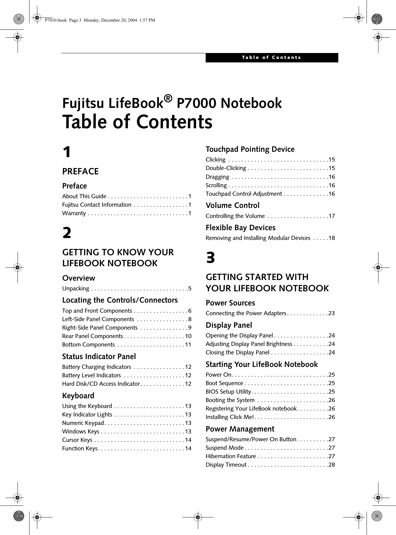
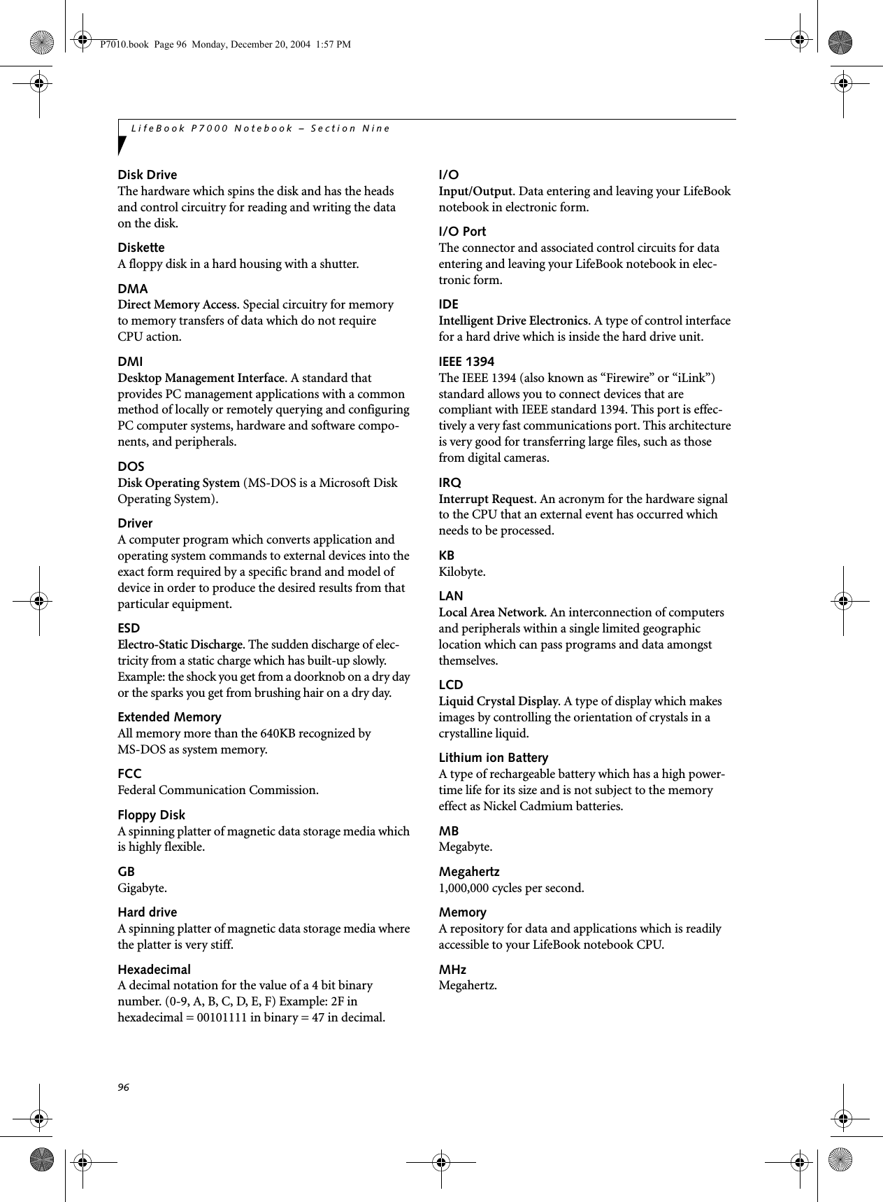
![13Getting to Know Your LifeBookFigure 2-9 KeyboardKeyboard USING THE KEYBOARDYour Fujitsu LifeBook notebook has an integral 82-key keyboard. The keys perform all the standard functions of a 101-key keyboard, including the Windows keys and other special function keys. This section describes the following keys. (Figure 2-9)■Numeric keypad: Your notebook allows certain keys to serve dual purposes, both as standard characters and as numeric and mathematical keys. The ability to tog-gle between the standard character and numerical keys is controlled through the [NumLk] key.■Cursor keys: Your keyboard contains four arrowkeys for moving the cursor or insertion point to the right, left, up, or down within windows, applications and documents. ■Function keys: The keys labeled [F1] through [F12], are used in conjunction with the [Fn] key to produce special actions that vary depending on what program is running. ■Windows keys: These keys work with your Windows operating system and function the same as the onscreen Start menu button, or the right buttonon your pointing device.KEY INDICATOR LIGHTSThere are three small indicator lights located on the lower right of the palm rest. (Figure 2-10). When lit, these lights indicate that the related key is locked. Figure 2-10 Key IndicatorsNUMERIC KEYPADCertain keys on the keyboard perform dual functions as both standard character keys and numeric keypad keys. NumLk can be activated by pressing the [NumLk] keys. Turning off the NumLk feature is done the same way. Once this feature is activated you can enter numerals 0 through 9, perform addition ( + ), subtraction ( - ),multiplication ( * ), or division ( / ), and enter decimal points ( . ) using the keys designated as ten-key function keys. The keys in the numeric keypad are marked on the front edge of the key to indicate their secondary functions. (Figure 2-9) WINDOWS KEYSYour LifeBook notebook has two Windows keys, consisting of a Start key and an Application key. The Start key displays the Start menu. This button functions the same as your onscreen Start menu button. The Fn Key WindowsFunction KeysNumeric KeypadCursor KeysWindowsApplication KeyStart KeyNum Lock IndicatorCaps Lock Indicator Scroll Lock Indicator P7010.book Page 13 Monday, December 20, 2004 1:57 PM](https://usermanual.wiki/Fujitsu-Client-Computing/WL0033.Users-Manual/User-Guide-552678-Page-21.png)
![14LifeBook P7000 Notebook – Section TwoApplication key functions the same as your right mouse button and displays shortcut menus for the selected item. (Please refer to your Windows documentation for additional information regarding the Windows keys.) (Figure 2-9)CURSOR KEYSThe cursor keys are the four arrow keys on the keyboard which allow you to move the cursor up, down, left and right in applications. In programs such as Windows Explorer, it moves the “focus” (selects the next item up, down, left, or right). (Figure 2-9)FUNCTION KEYSYour LifeBook notebook has 12 function keys, F1 through F12. The functions assigned to these keys differ for each application. You should refer to your software documentation to find out how these keys are used. (Figure 2-9)The [Fn] key provides extended functions for thenotebook and is always used in conjunction with another key. ■[Fn+F3]: Pressing [F3] while holding [Fn] will toggle the Audio Mute on and off.■[Fn+F4]: Pressing [F4] while holding [Fn] will toggle the Quick Point feature on and off. Note that the [Fn+F4] combination only works if Manual Setting is selected in the BIOS. (See “Entering the BIOS Setup Utility” on page 25)■[Fn+F5]: Pressing [F5] while holding [Fn] allows you to toggle between video compensation and no compensation. (Video compensation controls spacing on the display. When it is enabled, displays with 1024 x 768 or 800 x 600 pixel resolution will still cover the entire screen.) Note that this function is only applicable if Compensation is disabled in the BIOS. (See BIOS Setup Utility on page 25 for more informa-tion).■[Fn+F6]: Pressing [F6] repeatedly while holding [Fn] will lower the brightness of your display.*■[Fn+F7]: Pressing [F7] repeatedly while holding [Fn] will increase the brightness of the display.*■[Fn+F8]: Pressing [F8] repeatedly while holding [Fn] will decrease the volume of your LifeBook note-book.**■[Fn+F9]: Pressing [F9] repeatedly while holding [Fn] will increase the volume of your LifeBook notebook.**■[Fn+F10]: Pressing [F10] while holding [Fn] allows you to change your selection of where to send your display video. Each time you press the combination of keys you will step to the next choice. The choices, in order, are: built-in display panel only, both built-in display panel and external monitor or external monitor only.* There are eight brightness levels.** There are 26 audio levels.P7010.book Page 14 Monday, December 20, 2004 1:57 PM](https://usermanual.wiki/Fujitsu-Client-Computing/WL0033.Users-Manual/User-Guide-552678-Page-22.png)
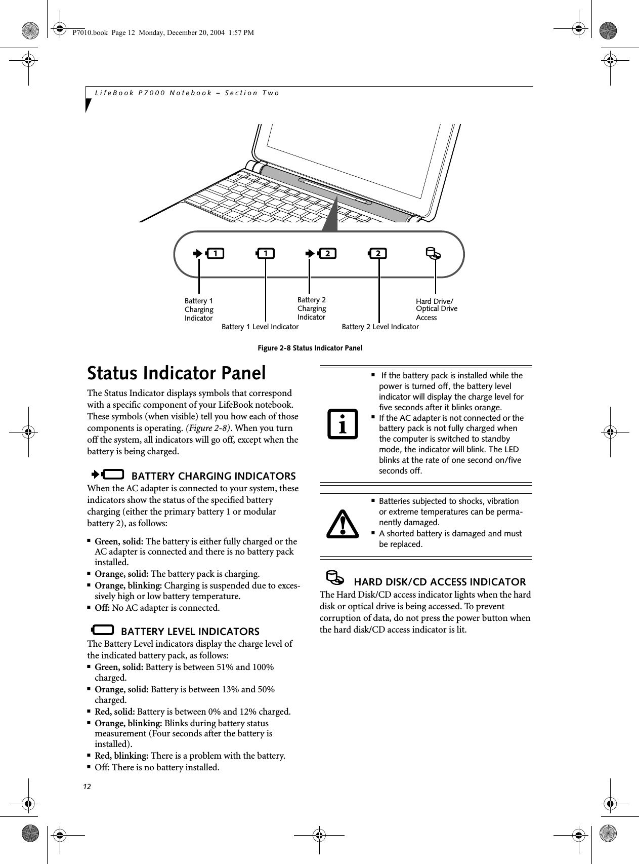
![17Getting to Know Your LifeBookVolume ControlYour Fujitsu LifeBook notebook has multiple volume controls which interact with each other. CONTROLLING THE VOLUMEThe volume can be controlled in several different ways:■Volume can be set from within the Volume Control on the Taskbar.■Volume can be controlled with the [F8] and [F9] functions keys. Pressing [F8] repeatedly while holding [Fn] will decrease the volume of your notebook. Press-ing [F9] repeatedly while holding [Fn] will increase the volume of your notebook.■Volume can be controlled by many volume controls that are set within individual applications.■Certain external audio devices you might connect to your system may have hardware volume controls.Each source discussed above puts an upper limit on the volume level that must then be followed by the other sources. We recommend that you experiment with the various volume controls to discover the optimal sound level.Any software that contains audio files will also contain a volume control of its own. If you install an external audio device that has an independent volume control, the hardware volume control and the software volume control will interact with each other. It should be noted that if you set your software volume to Off, you will override external volume control settings. There are 26 levels through which the function keys cycle. P7010.book Page 17 Monday, December 20, 2004 1:57 PM](https://usermanual.wiki/Fujitsu-Client-Computing/WL0033.Users-Manual/User-Guide-552678-Page-25.png)


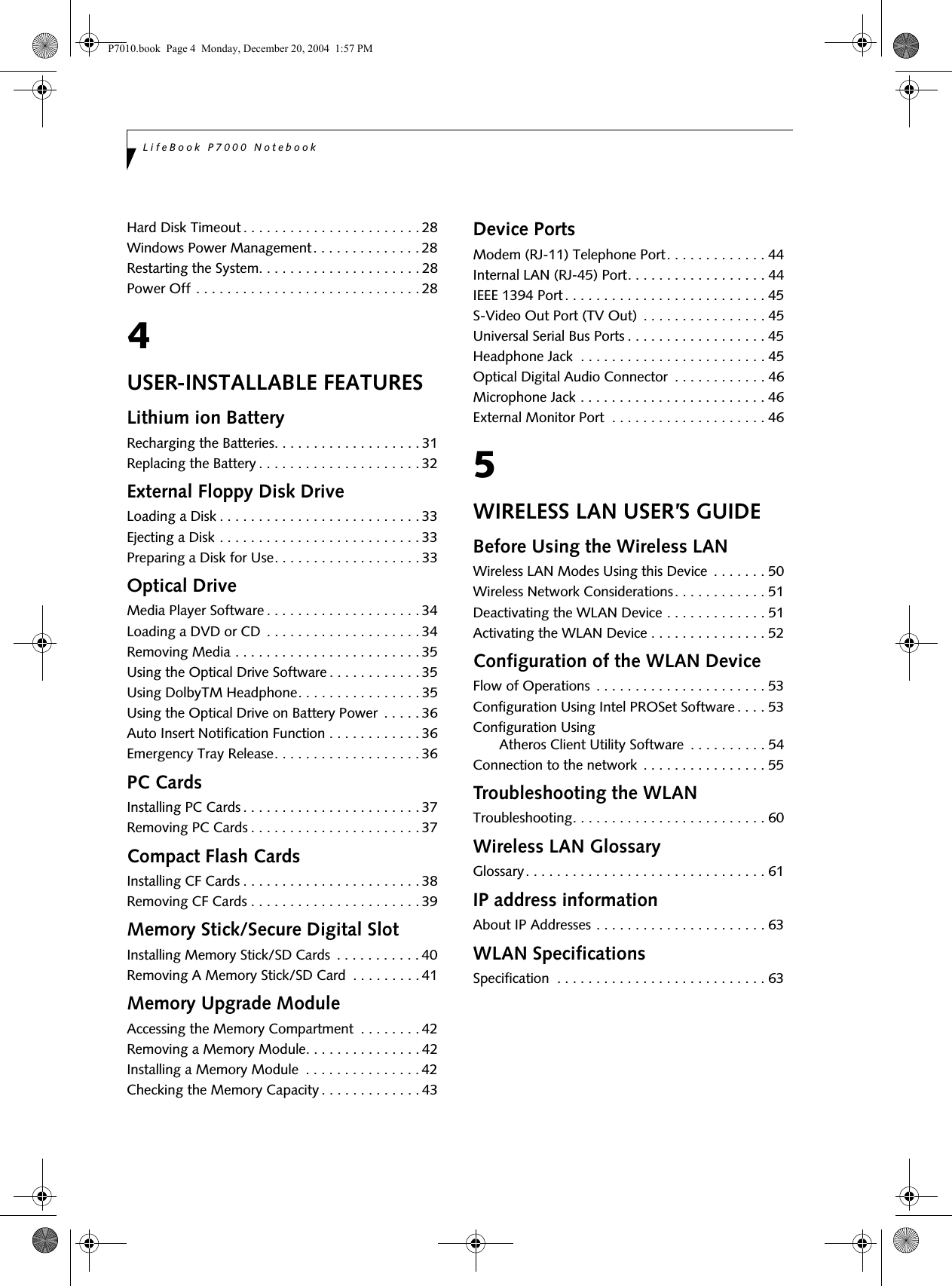
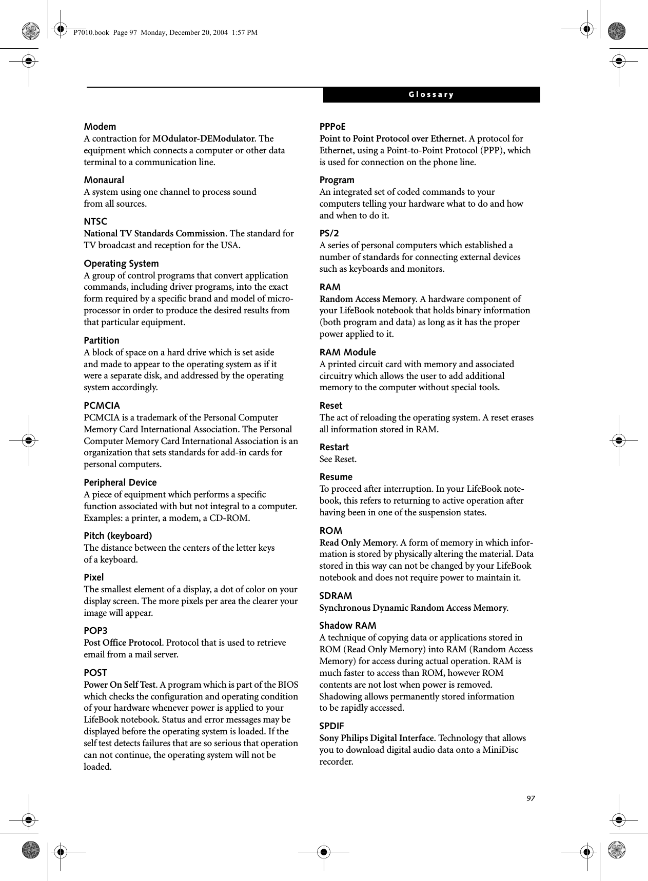
![24LifeBook P7000 Notebook – Section ThreeFigure 3-2 Opening the Display PanelDisplay PanelYour Fujitsu LifeBook notebook contains a display panel that is backlit for easier viewing in bright environments and maintains top resolution through the use of active-matrix technology. OPENING THE DISPLAY PANELLift the display backwards, being careful not to touch the screen, until it is at a comfortable viewing angle. (Figure 3-2)ADJUSTING DISPLAY PANEL BRIGHTNESSOnce you have turned on your LifeBook notebook, you may want to adjust the brightness level of the screen to a more comfortable viewing level. There are two ways to adjust the brightness, by using the keyboard or the power management utility. Using the KeyboardAdjusting the brightness using the keyboard changes the setting only temporarily. ■[Fn+F6]: Pressing repeatedly will lower thebrightness of your display.■[Fn+F7]: Pressing repeatedly will increase thebrightness of the display.CLOSING THE DISPLAY PANELHolding the edge of your display panel, pull it forward until it is flush with the body of your LifeBook notebook. P7010.book Page 24 Monday, December 20, 2004 1:57 PM](https://usermanual.wiki/Fujitsu-Client-Computing/WL0033.Users-Manual/User-Guide-552678-Page-32.png)
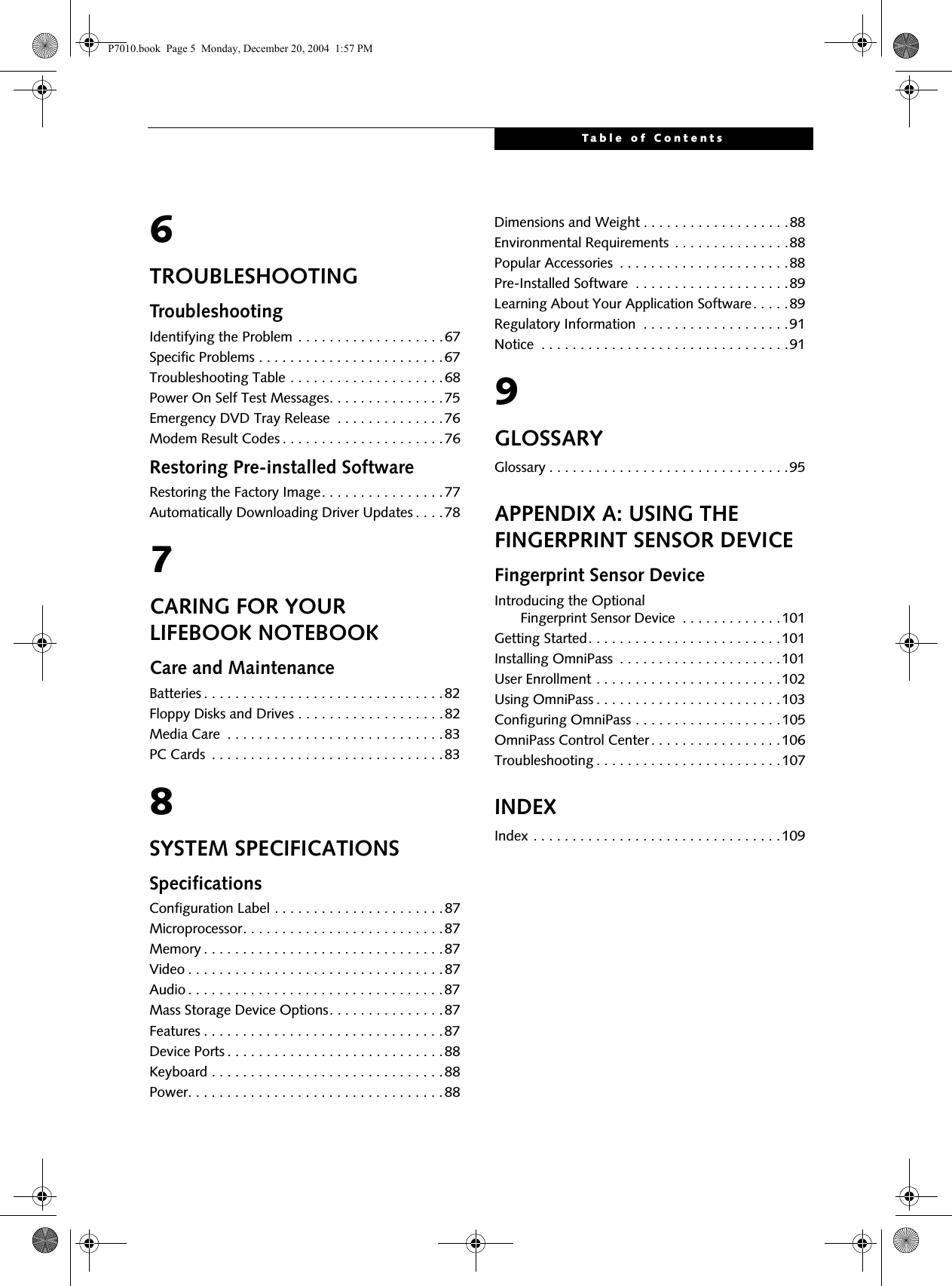
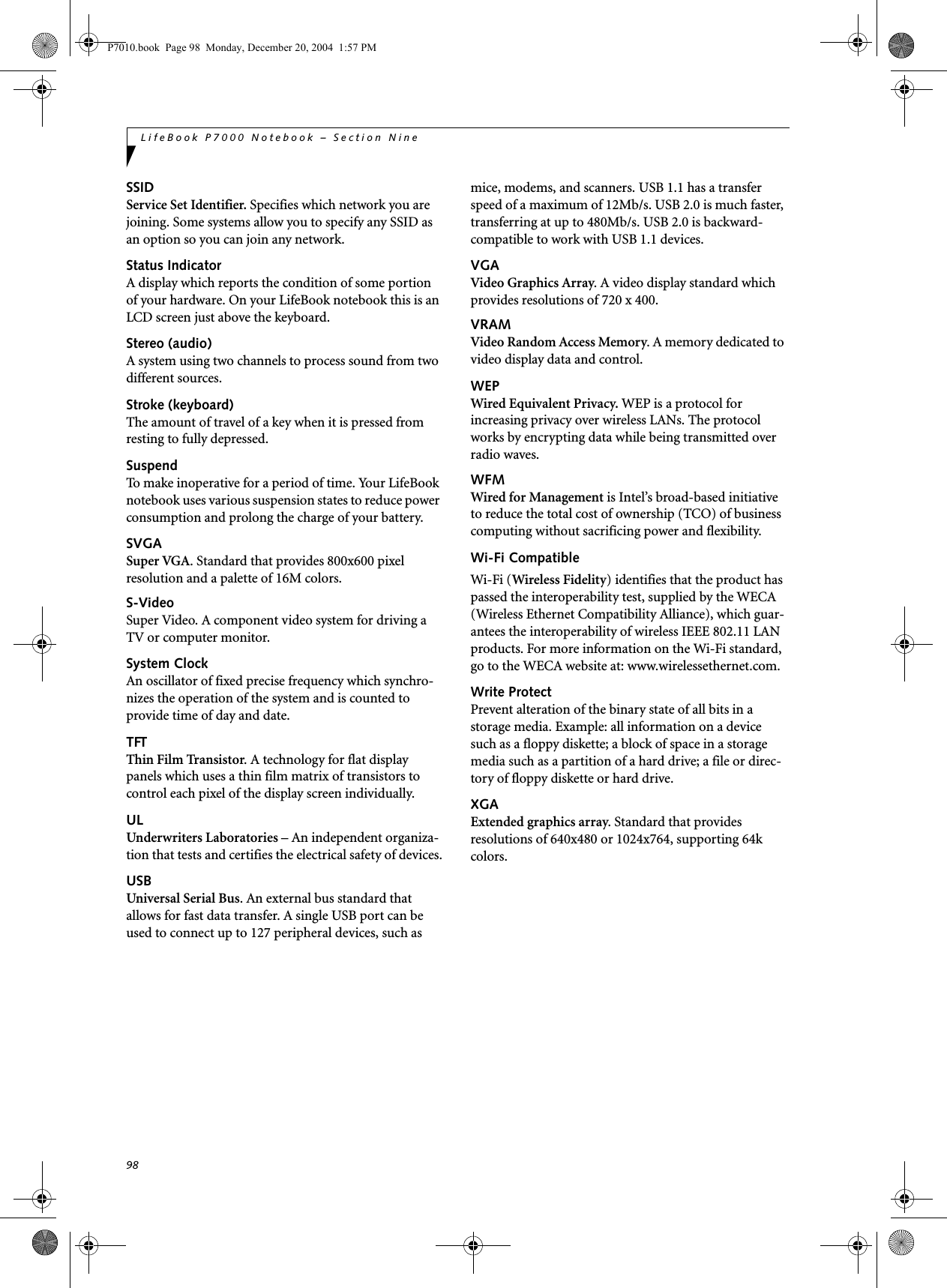
![25Getting StartedStarting Your LifeBook NotebookPOWER ONSuspend/Resume/Power On buttonThe Suspend/Resume/Power On button is used to turn on your LifeBook notebook from its off state. Once you have connected your AC adapter or charged the internal Lithium ion Battery, you can power on your notebook. Figure 3-3 Pressing the suspend/resume/power buttonPress the Suspend/Resume/Power On button that is adjacent to the status indicator panel (Figure 3-3). When you are done working you can either leave your LifeBook notebook in Suspend mode, (See Suspend Mode on page 27 for more information), or you can turn it off. (See Power Off on page 28 for more information)When turn on your LifeBook notebook, it will perform a Power On Self Test (POST) to check the internal parts and configuration for correct functionality. If a fault is found, your LifeBook notebook will emit an audio warning and/or an error message will be displayed. (See Power On Self Test Messages on page 75 for more information) Depending on the nature of the problem, you may be able to continue by starting the operating system or by entering the BIOS setup utility and revising the settings.After satisfactory completion of the Power On Self Test (POST), your notebook will load your operating system.BOOT SEQUENCEThe procedure for starting-up your notebook is termed the Bootup sequence and involves your notebook’s BIOS. When your LifeBook notebook is first turned on, the main system memory is empty, and it needs to find instructions to start up your notebook. This information is in the BIOS program. Each time you power up or restart your notebook, it goes through a boot sequence which displays a Fujitsu logo until your operating system is loaded. During booting, your notebook is performing a standard boot sequence including a Power On Self Test (POST). When the boot sequence is completed without a failure and without a request for the BIOS Setup Utility, the system displays the operating system’s opening screen.The boot sequence is executed when:■You turn on the power to your LifeBook notebook.■You restart your notebook from the WindowsShut Down dialog box.■The software initiates a system restart. Example:When you install a new application.■You reset the system by pressing the three keys [CTRL+ALT+DEL]. BIOS SETUP UTILITYThe BIOS Setup Utility is a program that sets up the operating environment for your LifeBook notebook. Your BIOS is set at the factory for normal operating conditions, therefore there is no need to set or change the BIOS’ environment to operate your notebook.The BIOS Setup Utility configures:■Device control feature parameters, such as changingI/O addresses and boot devices.■System Data Security feature parameters, such as passwords.Entering the BIOS Setup UtilityTo enter the BIOS Setup Utility do the following: 1. Turn on or restart your LifeBook notebook.2. Press the [F2] key once the Fujitsu logo appears on the screen. This will open the main menu of the BIOS Setup Utility with the current settings displayed.When you turn on your LifeBook note-book be sure you have a battery installed and charged, or that the AC or Auto/Air-line adapter is connected and has power.Do not carry your LifeBook notebook around with the power on or subject it to shocks or vibration, as you risk damaging your notebook.Status Indicator PanelSuspend/Resume/Power On ButtonNever turn off your LifeBook notebook during the Power On Self Test (POST) or it will cause an error message to be displayed the next time you turn on your LifeBook notebook. (See Power On Self Test Mes-sages on page 75 for more information)P7010.book Page 25 Monday, December 20, 2004 1:57 PM](https://usermanual.wiki/Fujitsu-Client-Computing/WL0033.Users-Manual/User-Guide-552678-Page-33.png)
![26LifeBook P7000 Notebook – Section Three3. Press the [RIGHT ARROW] or [LEFT ARROW] key to scroll through the other setup menus to review or alter the current settings.BIOS GuideA guide to your notebook’s BIOS is available online. Please visit our service and support Web site at http://www.computers.us.fujitsu.com/support. Once there, select Support, then select Notebooks under User’s Guides. Select LifeBook BIOS Guides from the pull-down menu for your LifeBook series. If you are unsure of your notebook’s BIOS number, refer to your packing slip.BOOTING THE SYSTEM We strongly recommend that you not attach any external devices and do not put a DVD/CD in your drive until you have gone through the initial power on sequence.When you turn on your LifeBook notebook for the first time, it will display a Fujitsu logo on the screen. If you do nothing the system will load the operating system, and then the Windows Welcome will begin.Designed to accommodate the needs of many users, in many different countries, Windows needs to be config-ured the first time you use them. Windows has three parts: ■Getting Started: You have the opportunity to enter custom information for your configuration file and setup your modem so that your LifeBook notebook will be prepared to dial out. ■Registration: Easy online registration for Windows with Microsoft, and for your LifeBook notebook with Fujitsu. ■Windows License Agreement and Final Settings:You have the opportunity to review the Windows License Agreement.Getting StartedRead the instructions on the screens carefully and fill in the information as directed. You will be asked for such items as the language you wish to use, the country in which you live, your first and last name, and about how you dial out from where you will be using your LifeBook notebook. For the modem settings, enter your current location information where you will be using your Life-Book notebook. If you are not connected to a phone line and plan to register at a later time, you may click the Skip button, and you will go directly to the condition of use page.Once you have set up your LifeBook notebook to dial out, Windows will make a free telephone call to test the settings. If the call is unsuccessful, you will be returned to the phone settings page where you may try to fix them. If you are unable to fix the settings please contact Fujitsu Service and Support. (See Fujitsu Contact Infor-mation on page 1 for more information). If you would simply like to move on, and register at a later time, you may click the Skip button, and you will go directly to the Condition of Use page.Windows RegistrationIf your connection is successful, you will go to a Registration Confirmation page. Enter the requested information, then check the box at the bottom to register your copy of Windows with Microsoft. Once you have finished, click the Next button to continue.Final SettingsThe first part of your final settings is the Windows End User License Agreement. Read the agreement carefully. When you finish reading you must accept or reject the terms of the agreement and then click on the Next button.REGISTERING YOUR LIFEBOOK NOTEBOOKHow do I register my LifeBook notebook?You can register your LifeBook by going to our Web site:us.fujitsu.com/computersYou will need to be set up with an Internet Service Provider (ISP) to use the last option. INSTALLING CLICK ME! The first time you boot up your system, you will see an icon called Click Me! in the Start folder or in the system tray in the bottom right of the screen. When you click the Click Me! icon, your system will automatically build the icon tray in the bottom right of the screen. These icons provide links to utilities that you will frequently access. You may click Cancel at any time within this process to shut down Windows. You may restart this process at any time in the future, but you must complete it in order to use your computer.■If you reject the terms of the license agreement you will be asked to review the license agreement for information on returning Windows or to shut down your LifeBook notebook.■You cannot use your LifeBook notebook until you have accepted the License Agreement. If you stop the process your notebook will return to the beginning of the Windows Welcome Process, even if you shut your notebook down and start it up again.P7010.book Page 26 Monday, December 20, 2004 1:57 PM](https://usermanual.wiki/Fujitsu-Client-Computing/WL0033.Users-Manual/User-Guide-552678-Page-34.png)
![27Getting StartedPower ManagementYour Fujitsu LifeBook notebook has many options and features for conserving battery power. Some of these features are automatic and need no user intervention, such as those for the internal modem. However, others depend on the parameters you set to best suit your oper-ating conditions, such as those for the display bright-ness. Internal power management for your notebook may be controlled from settings made in your operating system, pre-bundled power management application, or from settings made in BIOS setup utility.Besides the options available for conserving battery power, there are also some things that you can do to prevent your battery from running down as quickly.For example, you can create an appropriate power saving profile, put your notebook into Suspend mode when itis not performing an operation, and you can limit the use of high power devices. As with all mobile, battery powered computers, there is a trade-off betweenperformance and power savings.SUSPEND/RESUME/POWER ON BUTTONWhen your LifeBook notebook is active, the Suspend/Resume/Power On button can be used to manually put your notebook into Suspend mode. Push the button when your notebook is active, but not actively accessing anything, and immediately release the button. You will hear two short beeps and your system will enterSuspend mode. (See figure 2-3 on page 6 for location)If your LifeBook notebook is suspended, pushing the Suspend/Resume/Power On button will return your notebook to active operation. You can tell whether or not your system is in Suspend mode by looking at the Power indicator. (See figure 2-3 on page 6) If the indi-cator is visible and not flashing, your notebook is fully operational. If the indicator is both visible and flashing, your notebook is in Suspend mode. If the indicator is not visible at all, the power is off or your notebook is in Hibernation mode.SUSPEND MODESuspend or Standby mode in Windows saves the contents of your LifeBook notebook’s system memory during periods of inactivity by maintaining power to critical parts. This mode will turn off the CPU, the display, the hard drive, and all of the other internal components except those necessary to maintain system memory and allow for restarting. Your notebook can be put in Suspend mode by:■Pressing the Suspend/Resume/Power On button when your system is turned on.■Selecting Standby from the Windows Shut Down menu.■Timing out from lack of activity.■Allowing the battery to reach the Dead BatteryWarning condition.You can change the actions the computer takes when the lid is closed or buttons are pressed by clicking [Start] -> Control Panel. Double-click the Power Options icon and select the Advanced tab. Your LifeBook notebook’s system memory typically stores the file(s) on which you are working, open applica-tion(s) information, and any other data required to support the operation(s) in progress. When you resume operation from Suspend mode, your notebook will return to the point where it left off. You must use the Suspend/Resume/Power On button to resume operation, and there must be an adequate power source available, or your notebook will not resume.HIBERNATION FEATUREThe Hibernation feature saves the contents of yourLifeBook notebook’s system memory to the hard drive as a part of the Suspend/Resume mode. You can enable or disable this feature. ■If you are running your LifeBook note-book on battery power, be aware that the battery continues to discharge while your notebook is in Suspend mode, though not as fast as when fully opera-tional. ■Disabling the Suspend/Resume/Power On button prevents it from being used to put your LifeBook notebook in Suspend or Hibernation mode. The resume function of the button cannot be disabled.■If your LifeBook notebook is actively accessing information when you enter the Suspend or Hibernation mode, changes to open files are not lost. The files are left open and memory is kept active during Suspend mode or the memory is transferred to the internal hard drive during Hibernation mode.The Suspend or Hibernation mode should not be used with certain PC Cards. Check your PC Card documentation for more information.When PC Cards or external devices are in use, Hibernation mode cannot return to the exact state prior to suspension, because all of the peripheral devices will be re-initialized when the system restarts.P7010.book Page 27 Monday, December 20, 2004 1:57 PM](https://usermanual.wiki/Fujitsu-Client-Computing/WL0033.Users-Manual/User-Guide-552678-Page-35.png)

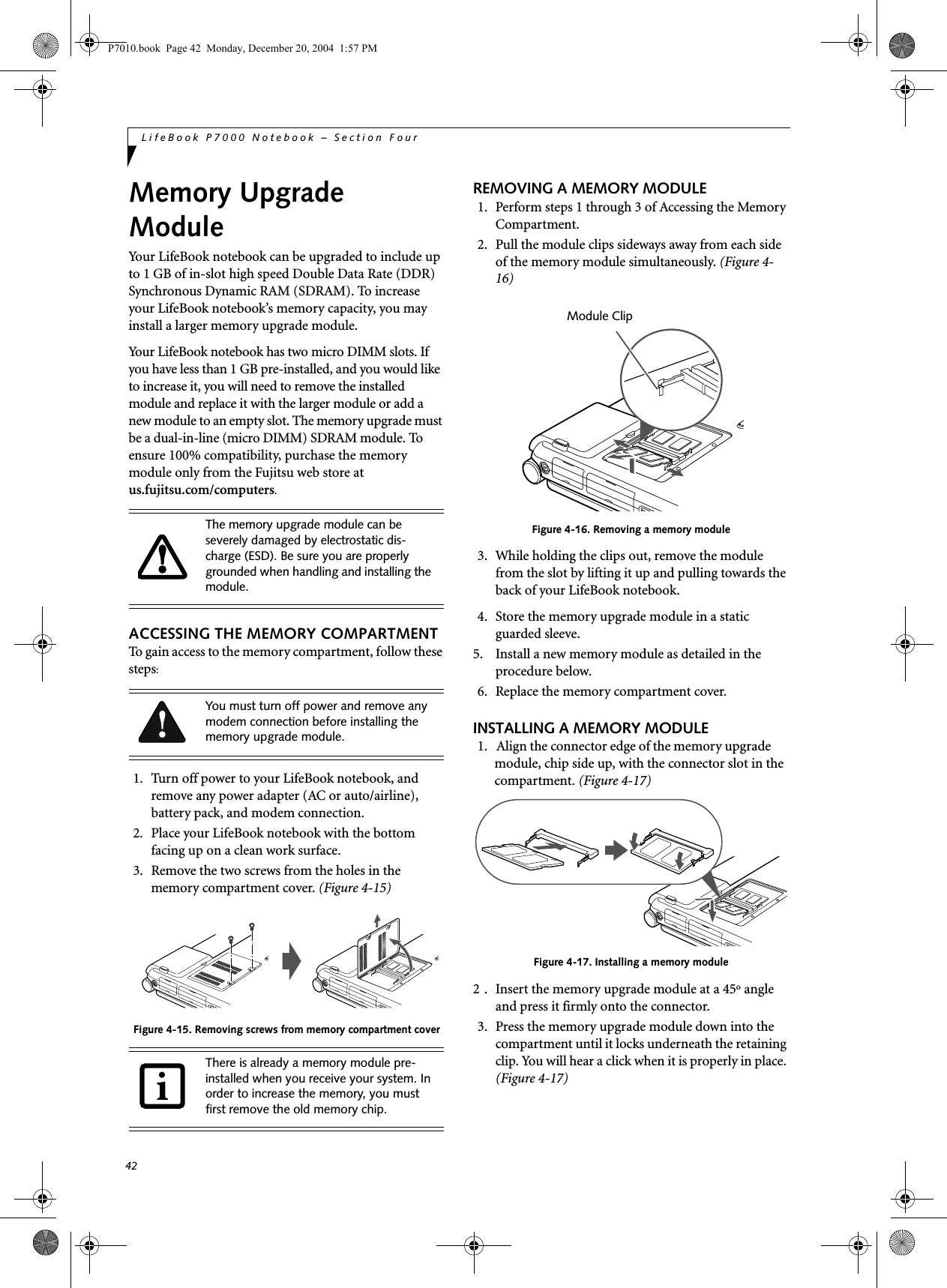
![43User Installable FeaturesCHECKING THE MEMORY CAPACITYOnce you have changed the system memory capacity by replacing the installed module with a larger one, be sure to check that your notebook has recognized the change.Check the memory capacity by clicking [Start] -> Settings -> Control Panel, then double-clicking the System icon. Select the General tab and check the amount of memory under “Computer:”.There may be a variation between the actual memory size and what is displayed. This is due to the fact that your system uses a video graphics chip which dynami-cally allocates system memory to accelerate graphics performance. Up to 64 MB of memory is dynamically shared on an as-needed basis using Dynamic Video Memory Technology (DVMT).The memory upgrade module is not something you routinely remove from your LifeBook notebook. Once it is installed, you should leave it in place unless you want to increase system memory capacity.If the total memory displayed is incorrect, check that your memory upgrade module is properly installed. (If the module is properly installed and the capacity is still not correctly recognized, see Trouble-shooting on page 67.P7010.book Page 43 Monday, December 20, 2004 1:57 PM](https://usermanual.wiki/Fujitsu-Client-Computing/WL0033.Users-Manual/User-Guide-552678-Page-51.png)
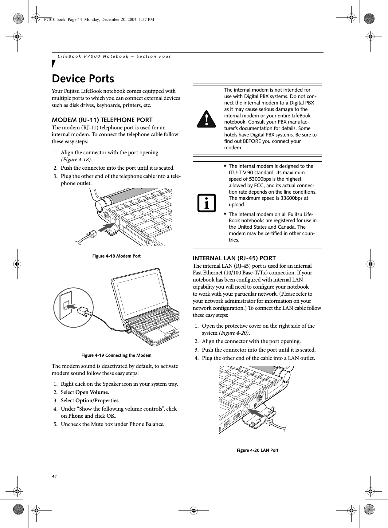
![46LifeBook P7000 Notebook – Section FourOPTICAL DIGITAL AUDIO CONNECTORThe optical digital audio-out connector allows you todownload digital audio to MiniDisc recorders. It uses SPDIF (Sony Philips Digital Interface) format. Use the following setting when using the digital audio-out connector. 1. Connect the MiniDisc recorder or external speaker to the Optical Digital Audio-Out Connector. (Figure 4-24)2. Insert the disk you want to play in the DVD/CD-RW tray.3. Click on Start -> Programs -> InterVideo WinDVD. (In Windows XP systems, you can go directly from Start to InterVideo WinDVD.)4. When the WinDVD interface appears, right-click in the WinDVD window and select [Setup] from the menu.5. Click on the Audio tab and select Enable S/PDIF output.6. Click [Apply].MICROPHONE JACKThe microphone jack allows you to connect an external mono microphone. Your microphone must be equipped with a 1/8”(3.5 mm) mono mini-plug in order to fit into the microphone jack of your notebook. In order to connect a microphone follow these easy steps: Figure 4-25 Microphone jack1. Align the connector with the port opening (Figure 4-25).2. Push the connector into the port until it is seated.EXTERNAL MONITOR PORTThe external monitor port allows you to connect an external monitor. In order to connect a monitor follow these easy steps: 1. Open the protective cover on the right side of the system (Figure 4-26).2. Align the connector with the port opening.3. Push the connector into the port until it is seated. Figure 4-26 Installing the External Monitor Cable■When headphones or a SPDIF cable is installed, the speakers are disabled.■Before using the SPDIF function, make sure that WinDVD software is installed on your system.■Certain older CDs and DVDs will not work in conjunction with the SPDIF con-nector.■The frequency of the digital sound output from the SPDIF output connector is fixed to 48KHz. If a sampling rate convertor is not installed in your connecting digital electronic device (e.g., MD player), recording is not possible. Please see the user manuals for the electronic devices for further details.■The sound recorded through connecting a digital electronic device (e.g., MD player) to the SPDIF output connector cannot be used as digital output. All output data from the SPDIF output connector has copyright protection information included.■Please be careful, as there are several types of cables for connecting a digital electronic device (e.g., MD player) to the digital audio-out connector, depend-ing on the connector type. The connec-tor on your computer is an Optical Mini Plug (3.5mm diameter mini plug)Pressing the [Fn] + [F10] keys allows you to change your selection of where to send your display video. Each time you press the key combination, you will step to the next choice, starting with the built-in display panel only, moving to the external monitor only, finally moving to both the built-in display panel and an external monitor.Microphone JackP7010.book Page 46 Monday, December 20, 2004 1:57 PM](https://usermanual.wiki/Fujitsu-Client-Computing/WL0033.Users-Manual/User-Guide-552678-Page-54.png)


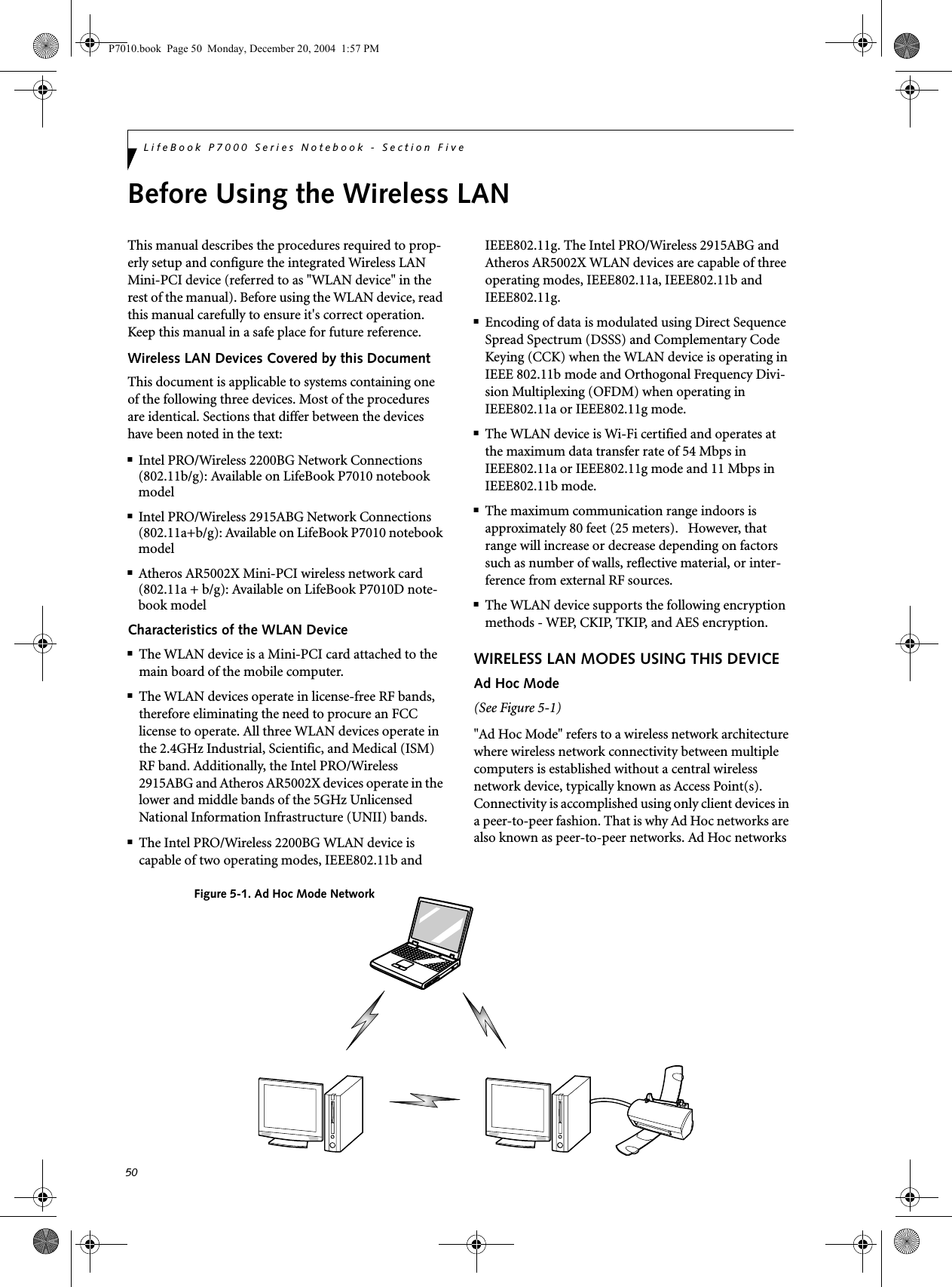
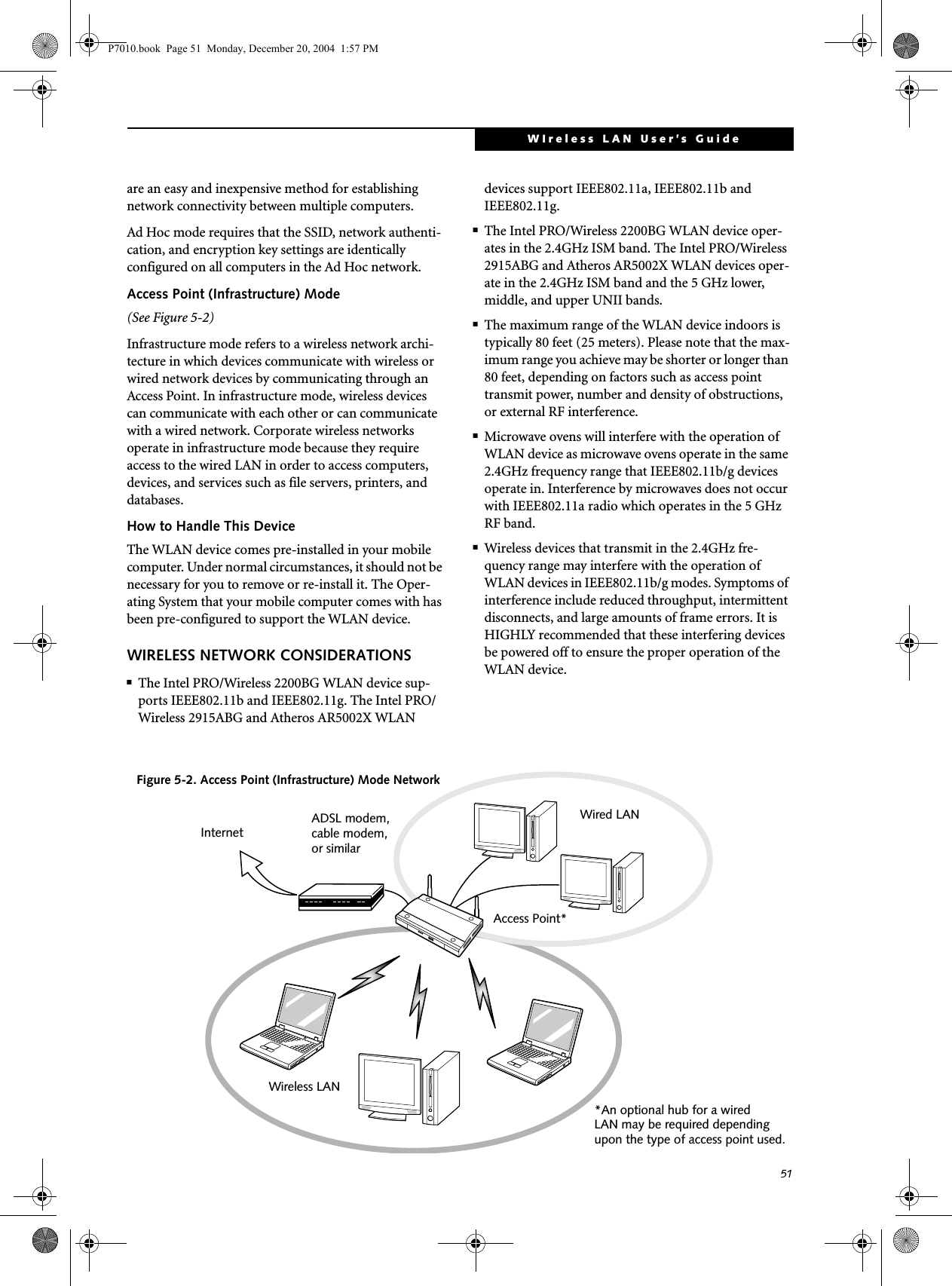
![52LifeBook P7000 Series Notebook - Section FiveDEACTIVATING THE WLAN DEVICEDeactivation of the WLAN device may be desired in certain circumstances (to extend battery life) or where certain environments require it (i.e. hospitals, clinics, airplanes, etc.). Fujitsu mobile computers employ two methods with which to deactivate the WLAN device:■Using the Wireless On/Off Switch■In Windows, using the Intel PROSet Software or Atheros Client Utility software.Deactivation using the Wireless On/Off SwitchThe WLAN device can be deactivated quickly and effi-ciently by toggling the Wireless On/Off Switch to the Off position. (Figure 5-3)The Wireless On/Off switch has no effect on non-Wire-less LAN models.Figure 5-3. Wireless LAN On/Off Switch LocationDeactivation using the Intel PROSet SoftwareThe WLAN device can also be deactivated in Windows using the Intel PROSet Software. The procedure to accomplish this:1. Click [Start]-> [All Programs].2. Select Intel ProSet Wireless, then click on Intel ProSet Wireless from the menu that appears. The Intel ProSet Wireless utility will be displayed.3. At the bottom left corner of the window, select Wireless Off from the dropdown list.Deactivation using Atheros Client Utility software1. Right-click on Atheros Client Utility icon in the system tray. Select “Open Atheros Client Utility” from the menu.2. Choose Action and click Disable Radio.ACTIVATING THE WLAN DEVICEActivation of the WLAN device can be accomplished using the same methods as the deactivation process■Using the Wireless On/Off Switch■In Windows using the Intel PROSet Software or Atheros SoftwareWireless LANOn/Off SwitchOnOffP7010.book Page 52 Monday, December 20, 2004 1:57 PM](https://usermanual.wiki/Fujitsu-Client-Computing/WL0033.Users-Manual/User-Guide-552678-Page-60.png)
![53WIreless LAN User’s Guide Configuration of the WLAN DeviceThe WLAN Device can be configured to establish wire-less network connectivity using one of the following tools:■Intel PROSet Software - The Intel PROSet Software allows for multiple profile setup and supports auto-matic profile switching. Support for most industry standard security solutions is contained in this soft-ware.■Atheros Client Utility - The Atheros Client Utility soft-ware allows for multiple profile setups and supports automatic profile switching. Support for most indus-try standard security solutions is contained in this software.FLOW OF OPERATIONS1. Activate the WLAN Device (See Activating the WLAN Device on page 52 for more information).2. Configure the Wireless Network parameters (See Configure Wireless Network Parameters on page 53 for more information).■Enter the network name (SSID)■Choose the appropriate WLAN architecture (Ad Hoc or Infrastructure)■Choose Authentication method: Open, Shared, WPA-Enterprise, WPA2-Enterprise, WPA-Personal, or WPA2-Personal■If using static WEP keys, enter static WEP key and choose key index. 3. Configure network settings (See Configure Net-work Parameters on page 53 for more information)■TCP/IP settings■Workgroup or Domain settings.CONFIGURATION USING INTEL PROSET SOFTWAREThis section explains the procedure to properly configure the WLAN device using the Intel PROSet Soft-ware. Pre-defined parameters will be required for this procedure. Please consult with your network adminis-trator for these parameters:Network Name - Also known as the SSIDNetwork Key (WEP) - Required if using static WEP keys. Authentication Type - Open, Shared, WPA, or WPA-PSKProcedure1. Activate the WLAN device using either the Wireless On/Off Switch or the Intel PROSet software.2. Click the [Start] button first and then [All Pro-grams].3. Click the icon [Intel PROSet Wireless] to execute the Intel PROSet Wireless software.4. Click the [Add] button. The General Settings dialog displays. 5. Enter a profile name in the Profile Name field. 6. Enter the network SSID, in the Network Name (SSID) field. 7. Click Infrastructure or Ad Hoc for the operating mode. 8. Click [Advanced].9. The Mandatory Access Point option is only used if Infrastructure mode is selected. Use this option to connect to a specific access point. Enter the MAC address for the access point. Click OK to save the setting and return to the General Settings page. 10. Click [Next].11. If you are using Cisco CCX, click Cisco Options to enable Cisco CKIP data encryption on the Security Settings page. Check the Cisco Compatible Exten-sions Options. If you have checked the Cisco's "Mixed-Cell" box in the Advanced Setting, this option must also be checked.12. Click [OK].13. Click Next.14. Select Open, Shared, WPA-Enterprise, WPA2-Enterprise, WPA-Personal, or WPA2-Personal in the Network Authentication options. 15. Select either None, WEP, CKIP (if Enable Cisco Cli-ent eXtentions is enabled, use CKIP or WEP), or TKIP for the data encryption. 16. If WEP is selected, select either 64 or 128-bit for the Encryption Level. 17. Select the key index 1, 2, 3 or 4. 18. Enter the WEP key if required. If your network does not employ a 802.1x/EAP security mechanism, please skip to step 24.P7010.book Page 53 Monday, December 20, 2004 1:57 PM](https://usermanual.wiki/Fujitsu-Client-Computing/WL0033.Users-Manual/User-Guide-552678-Page-61.png)
![54LifeBook P7000 Series Notebook - Section Five19. Click the Enable 802.1x checkbox to enable the 802.1x security option. Please contact your network administrator if configuration of this setting is required.20. Select the appropriate Authentication Type. Please contact your network administrator if configura-tion of this setting is required.21. After selecting your authentication type, enter the user name, domain, and password of the user you have created on the authentication server. The user name and password do not have to be the same as name and password of your current Windows user login.22. Click [OK] to save the settings.23. From the Intel ProSet Wireless page, click the new profile name shown in the Profile List. Use the up and down arrows to position the priority of the new profile in the priority list. 24. Click the Connect button to connect to the net-work. 25. Click [Close] if you want to close the Intel(R) PROSet for Wireless window.CONFIGURATION USING ATHEROS CLIENT UTILITY SOFTWAREThis section explains the procedure to properly configure the WLAN device using the Atheros Client Utility. Pre-defined parameters will be required for this procedure. Please consult with your network adminis-trator for these parameters:Network Name - Also known as the SSIDNetwork Key (WEP) - Required if using static WEP keys. Authentication Type - Open, Shared, WPA, or WPA-PSKProcedure1. Activate the WLAN device using either the Wireless On/Off Switch or the Atheros Client Utility2. Right-click on the “Atheros Client Utility” icon in the system tray, and select “Open Atheros Client Utility” from the menu.3. From the Current Status page, click the Profile Management tab. 4. If this is your first time using this utility, highlight the profile [Default] and Click the [Modify] button, otherwise Click the [New] button. The General Set-tings dialog displays. 5. From the General page, enter a profile name in the Profile Name field. 6. Enter the network SSID, in the SSID1 field. If you wish to create a profile that can connect to up to 3 different wireless networks, SSID's can be entered in the SSID2 and SSID3 fields as well.7. Click the Security tab. 8. The Security tab allows for the configuration of the Security modes listed in the table below. Please select the radio button of the desired security mode. If these settings are not known to you, please consult with your network administrator for the correct settings. 9. Click OK10. Click the Advanced tab11. The Advanced tab allows for the configuration of the options detailed in the table below.Field Name DescriptionWPA Enables the use of Wi-Fi Protected Access. Choosing WPA opens the WPA EAP drop-down menu. Options include TLS and PEAP. If these settings are not known to you, please consult with your network administrator for the correct settings. WPA-PSK Enables WPA-Pre-Shared Key. Click on the Configure button to enter the WPA Passphrase. If these settings are not known to you, please consult with your network administrator for the correct settings. 802.1x Enables 802.1x security. If these settings are not known to you, please consult with your network administrator for the correct settings. Choosing this option opens the 802.1x EAP type drop-down menu. Options include TLS, PEAP, and LEAPPre-Shared Key Enables the use of pre-shared keys that are defined on both the access point and the station. This is where static WEP keys are entered. Click the Configure button to fill in the Define Pre-Shared Keys window.None No securityP7010.book Page 54 Monday, December 20, 2004 1:57 PM](https://usermanual.wiki/Fujitsu-Client-Computing/WL0033.Users-Manual/User-Guide-552678-Page-62.png)
![55WIreless LAN User’s Guide .12. Click OK13. If the profile you just created does not activate immediately, click the Profile Management tab, highlight the desired Profile, and click Activate.14. Click [Close] if you want to close the Atheros Client Utility.CONNECTION TO THE NETWORKThis section explains connection to the network.If there is an administrator of the network, contact the network administrator for data settings.Setting the networkPerform the “Setting TCP/IP” and “Confirming the computer and work group names” operations required for network connection.Setting TCP/IP1. Click the [Start] button first and then [Control Panel].2. If the Control Panel is in Category view, switch to Classic view by clicking “Switch to Classic View” under Control Panel the left frame. (If you are already in Classic view, “Switch to Category View” will be displayed.) 3. Double-click [Network Connections]. A list of cur-rently installed networks will be displayed.4. Right-click [Wireless Network Connection] in the list, and then click [Properties] in the menu dis-played. The [Wireless Network Connection Proper-ties] window will be displayed.5. Click the [General] tab if it is not already selected.6. Click [Internet Protocol (TCP/IP] and then click [Properties]. The [Internet Protocol (TCP/IP) Properties] window will be displayed.7. Set the IP address as follows:■For ad hoc connection: Select [Use the following IP address:] and then enter data for [IP address] and [Subnet mask]. See page 62 for IP address setting.■For access point (infrastructure) connection: If your network uses DHCP, select [Obtain an IP address automatically] and [Obtain DNS server address automatically]. If your network uses static IP addresses, consult with your network adminis-trator for the correct IP address settings.8. Click the [OK] button. Processing will return to the [Wireless Network Connection Properties] window.9. Click the [OK] button.10. Close the [Network Connection] window. Following this operation, confirm the names of the computer and the workgroup as follows.Confirming the computer and work group names1. Click the [Start] button, then [Control Panel].2. If the Control Panel is in Category view, switch to Classic view by clicking “Switch to Classic View” under Control Panel the left frame. (If you are already in Classic view, “Switch to Category View” will be displayed.) 3. Double-click the [System] icon. The [System Prop-erties] window will be displayed.4. Click the [Computer Name] tab.Field Name DescriptionPower Save ModeOptions are Maximum, Normal, or OffNetwork Type Options are AP (Infrastructure) or Ad Hoc802.11b PreambleSpecifies the preamble setting in 802.11b. The default setting is Short and Long (Access Point mode), which allows both short and long headers in the 802.11b frames. Set to Long Only to override allowing short frames.Transmit Power LevelOptions are 100%, 50%, 25%, 12.5% or Lowest transmit power (0mW)Wireless Mode Specifies 5 GHz 54 Mbps, 5 GHz 108 Mbps, 2.4 GHz 11 Mbps, or 2.4 GHz 54 Mbps operation in an access point network.Wireless Mode when Starting Ad Hoc NetworkSpecifies 5GHz 54 Mbps, 5 GHz 108 Mbps, 2.4 GHz 11 Mbps, or 2.4 GHz 54 Mbps to start an Ad Hoc network if no matching network name is found after scanning all available modes.To change the setting of the IP address, you need to be logged in from Windows as an administrator.To modify the computer name and/or the work group name, you need to be logged in from Windows as an administrator.P7010.book Page 55 Monday, December 20, 2004 1:57 PM](https://usermanual.wiki/Fujitsu-Client-Computing/WL0033.Users-Manual/User-Guide-552678-Page-63.png)
![56LifeBook P7000 Series Notebook - Section Five5. Confirm the settings of [Full computer name:] and [Workgroup:].a. The setting of [Full computer name:] denotes the name for identifying the computer. Any name can be assigned for each personal computer. Enter the desired name in less than 15 ASCII character code format. Identifiability can be enhanced by entering the model number, the user name, and other factors.b. [Workgroup name] is the group name of the network. Enter the desired name in less than 15 ASCII character code format.For ad hoc connection: Assign the same network name to all personal computers existing on the network.For access point (infrastructure) connection: Assign the name of the work group to be accessed.6. Click the [OK] button. If a message is displayed that requests you to restart the personal computer, click [Yes] to restart the computer.Setting the sharing functionSet the sharing function to make file and/or printer sharing with other network-connected personal computers valid.This operation is not required unless the sharing func-tion is to be used.The folder and printer for which the sharing function has been set will be usable from any personal computer present on the network.Setting the Microsoft network-sharing service1. Click the [Start] button first and then [Control Panel]. 2. If the Control Panel is in Category view, switch to Classic view by clicking “Switch to Classic View” under Control Panel the left frame. (If you are already in Classic view, “Switch to Category View” will be displayed.) 3. Double-click [Network Connections]. A list of cur-rently installed networks will be displayed.4. Right-click [Wireless Network Connection] in the list, and then click [Properties] in the menu dis-played. The [Wireless Network Connection Proper-ties] window will be displayed.5. If [File and Printer Sharing for Microsoft Net-works] is displayed, proceed to step 6. If [File and Printer Sharing for Microsoft Networks] is not dis-played, skip to step 7.6. Make sure that the [File and Printer Sharing for Microsoft Networks] check box is checked, and then click the [OK] button. Skip to “Setting file-sharing function”.7. Click [Install]. The [Select Network Component Type] window will be displayed.8. Click [Service], then click the [Add] button. The [Select Network Service] window will be displayed.9. Click [File and Printer Sharing for Microsoft Net-works] and then click the [OK] button. Processing will return to the [Wireless Network Connection Properties] window, and [File and Printer Sharing for Microsoft Networks] will be added to the list.10. Click the [Close] button.Setting the file-sharing functionThe procedure for setting the file-sharing function follows, with the “work” folder in drive C: as an example.1. Click the [Start] button first and then [My Com-puter]. 2. Double-click [Local disk (C:)].3. Right-click the “work” folder (or whichever folder you want to share), and then click [Sharing and Security...] in the menu displayed. The [Folder Name Properties] window will be displayed.4. Click [Sharing] if it isn’t already selected.To change the name, click [Change] and then proceed in accordance with the instruction messages displayed on the screen.To share a file and/or the connected printer, you need to be logged in as an administrator. Setting the file-sharing function for the file which has been used to execute Network Setup Wizard is suggested on the screen. For the wireless LAN, however, since security is guaranteed by entry of the network name (SSID) and the network key, the steps to be taken to set the file-sharing function easily without using Network Setup Wizard are given below.P7010.book Page 56 Monday, December 20, 2004 1:57 PM](https://usermanual.wiki/Fujitsu-Client-Computing/WL0033.Users-Manual/User-Guide-552678-Page-64.png)
![57WIreless LAN User’s Guide 5. Click the link stating “If you understand the secu-rity risks, but want to share files without running the wizard, click here”.6. Click “Just enable file sharing” and click [OK].7. Check the [Share this folder on the network] check box.8. Click the [OK] button. The folder will be set as a sharable folder, and the display of the icon for the “work.” folder will change.Setting the printer-sharing function1. Click the [Start] button first and then [Printers and FAX]. A list of connected printers will be displayed.2. Right-click the printer for which the sharing func-tion is to be set, and then click [Sharing] in the menu displayed. The property window correspond-ing to the selected printer will be displayed.3. Click the [Sharing] tab.4. Click [Share this printer].5. Enter the sharing printer name in [Share name].6. Click the [OK] button. Confirming connectionAfter you have finished the network setup operations, access the folder whose sharing has been set for other personal computers. Also, confirm the status of the radio waves in case of trouble such as a network connection failure.Connecting your personal computer to another personal computer1. Click [Start] first and then [My Computer]. The [My Computer] window will be displayed in the left frame.2. Click [My Network Places] in the “Other Places” list. The window [My Network Places] will be dis-played.3. Click [View workgroup computers] under Network Tasks in the left frame.4. Double-click the personal computer to which your personal computer is to be connected. The folder that was specified in “Setting the file-sharing func-tion” on page 56 will be displayed.5. Double-click the folder to be accessed.Confirming the status of the radio1. Right-click the Intel PRO Wireless icon in the lower right corner of the screen.2. Click [Open Intel PROSet for Wireless]. The Intel PROSet for Wireless window opens.3. Contained within the General tab and the Details section (accessed by pressing the [Details] button), you will find the current operating status of the radio. (When the radio is turned off or the com-puter is not yet connected, some of the conditions will not be displayed.)■Profile NameThe current configuration profile is displayed.■Network Name (SSID)Displays the Network Name (SSID) currently used by the radio.■IP AddressThe IP address of the current profile.■Signal QualityDisplays a message stating the current quality of the signal.■Signal StrengthDisplays a graphic representation of the current signal strength.Additionally, in the lower section of the display, you will see a variety of different measurements related to the WLAN. For additional information about the items, click on the “Help?” button:■Adapter MAC Address■Band■Supported Data RatesTo specify the corresponding folder as a read-only folder, select the [Read only] checkbox under the General tab.Setting the printer-sharing function when Network Setup Wizard has been executed is suggested on the screen. For the wireless LAN, however, since security is guaranteed by entry of the network name (SSID) and the network key, the steps to be taken to set the printer-sharing function without using Network Setup Wizard are laid down below.In the case of access point (infrastructure) connection, enter the necessary data for the access point before confirming connection. Refer to the manual of the access point for the access point setup procedure.P7010.book Page 57 Monday, December 20, 2004 1:57 PM](https://usermanual.wiki/Fujitsu-Client-Computing/WL0033.Users-Manual/User-Guide-552678-Page-65.png)

![62LifeBook P7000 Series Notebook - Section FiveIP address informationIf IP address is unknown, set IP address as follows:If you have an access point (DHCP server) on the network, set the IP address as follows:[Obtain an IP address automatically]If the IP address is already assigned to the computer in the network, ask the network administrator to check the IP address to be set for the computer.If no access point is found in the network:An IP address is expressed with four values in the range between 1 and 255.Set the each computer as follows: The value in paren-theses is a subnet mask.<Example>Computer A: 192.168.100.2 (255.255.255.0)Computer B: 192.168.100.3 (255.255.255.0)Computer C: 192.168.100.4 (255.255.255.0)::Computer X: 192.168.100.254 (255.255.255.0)IP addressing is much more complicated than can be briefly explained in this document. You are advised to consult with your network administrator for additional information.A DHCP server is a server that automatically assigns IP addresses to computers or other devices in the network. There is no DHCP server for the AdHoc network.P7010.book Page 62 Monday, December 20, 2004 1:57 PM](https://usermanual.wiki/Fujitsu-Client-Computing/WL0033.Users-Manual/User-Guide-552678-Page-70.png)


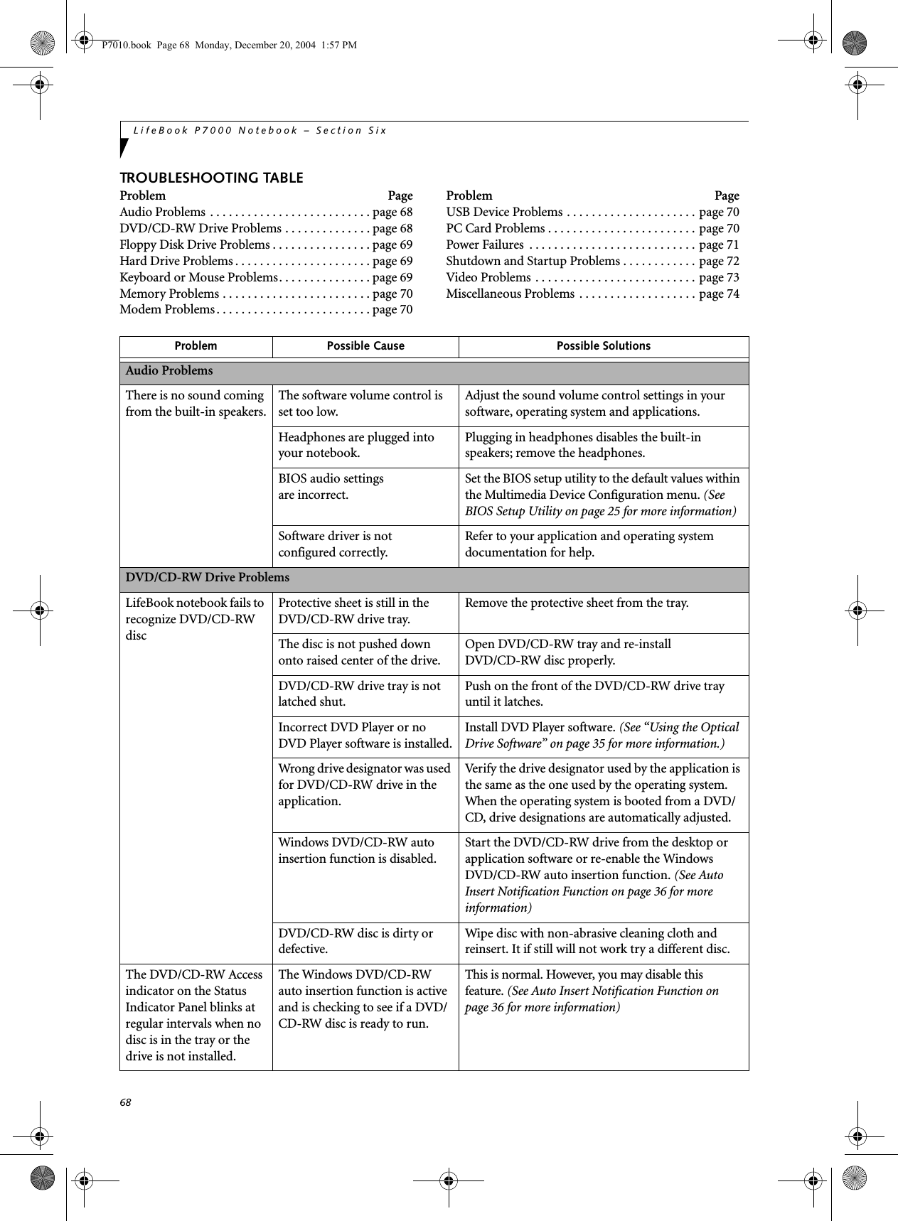
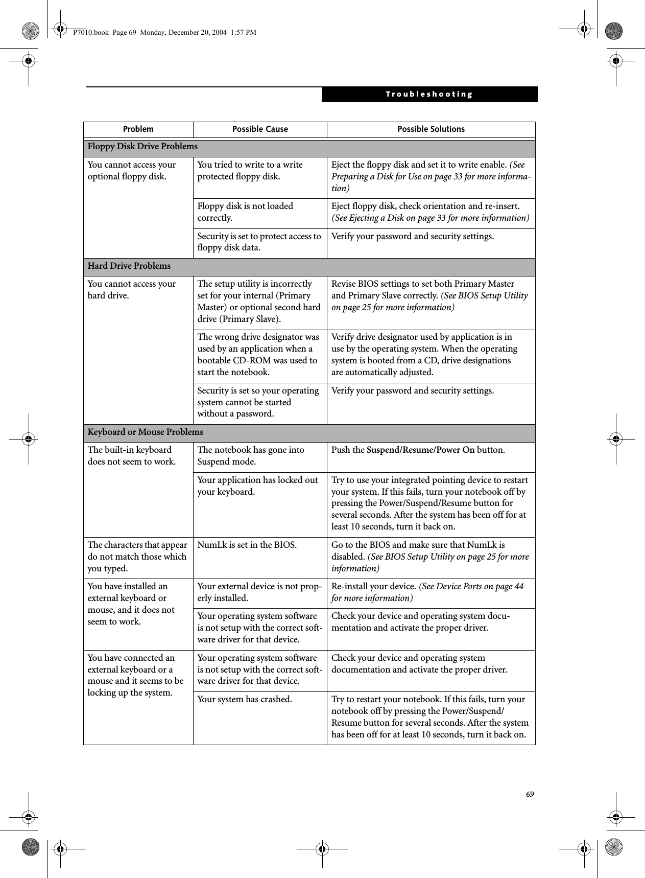
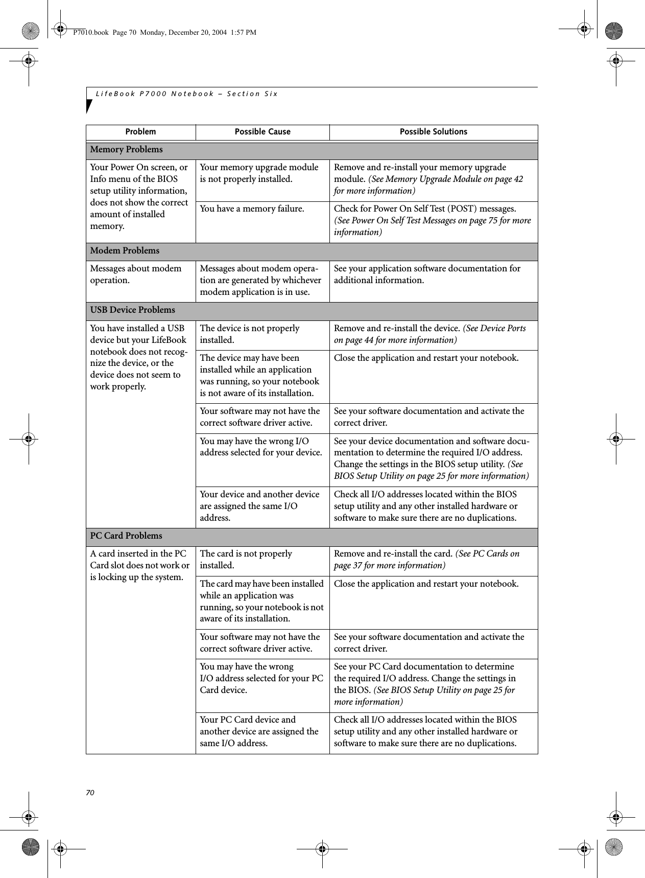
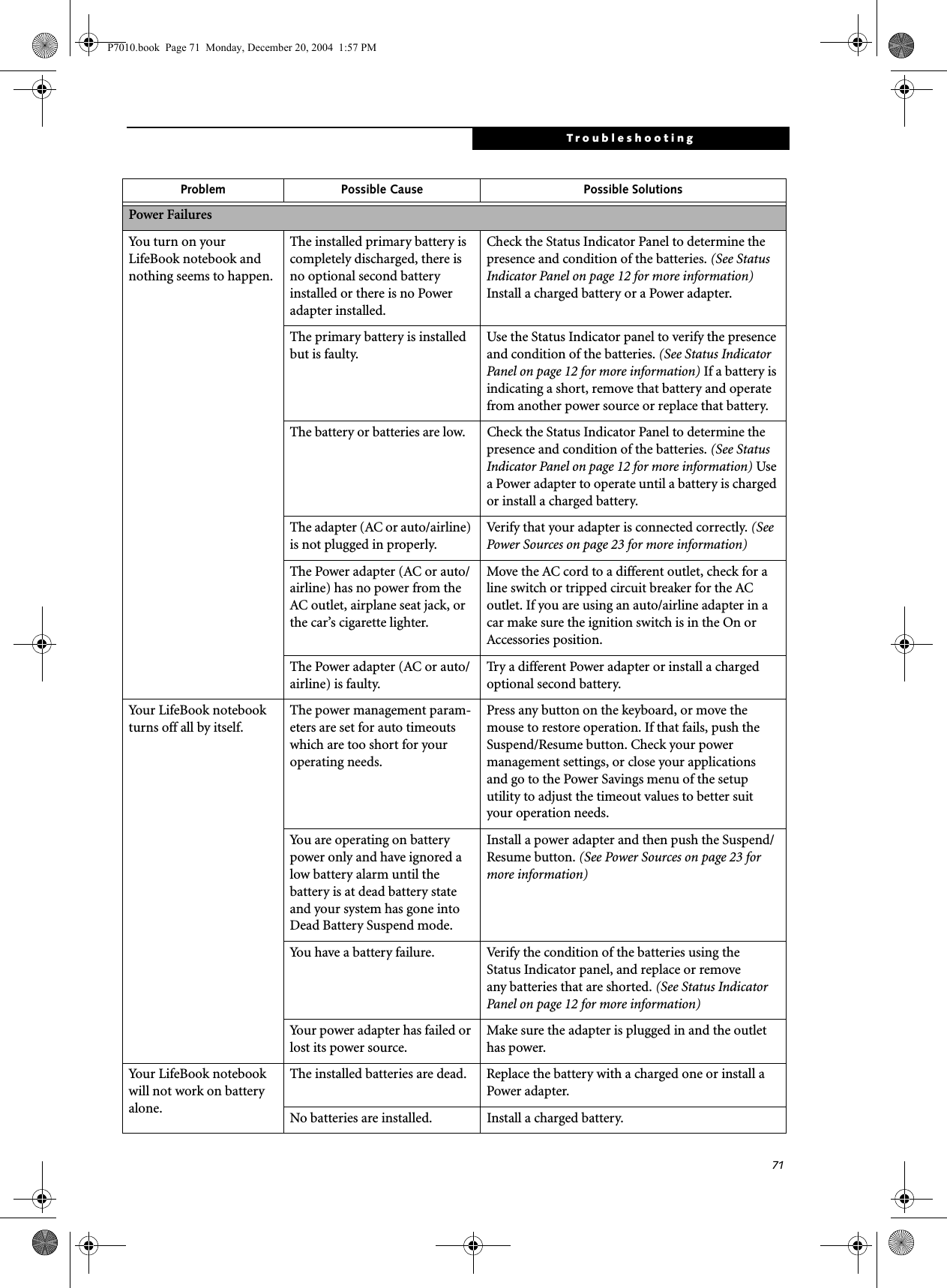
![72LifeBook P7000 Notebook – Section SixYour LifeBook notebook will not work on battery alone.(continued)The batteries are improperly installed.Verify that the batteries are properly connected by re-installing them.Your installed batteries are faulty.Verify the condition of the batteries using the Status Indicator panel and replace or remove any batteries that are shorted. (See Status Indicator Panel on page 12 for more information)The batteries seem to discharge too quickly.You are running an application that uses a lot of power due to frequent hard drive or DVD/CD-RW drive access, or use of a modem or LAN PC card.Use both the primary battery and an optional second battery and/or use a power adapter for this application when at all possible.The power savings features may be disabled.Check the power management and/or setup utility settings in the Power Savings menu and adjust according to your operating needs.The brightness is turned all the way up.Turn down the brightness adjustment. The higher the brightness the more power your display uses.The batteries are very old. Replace the batteries.The batteries have been exposed to high temperatures.Replace the batteries.The batteries are too hot or too cold. Restore the notebook to normal operating tempera-ture. The Charging icon on the Status Indicator panel will flash when the battery is outside itsoperating range.Shutdown and Startup ProblemsThe Suspend/Resume/Power On button does not work.The Suspend/Resume/Power On button is disabled from the Advanced submenu of the Power menu of the setup utility. Enable the button from the setup utility.You did not hold the button in long enough.Hold the button longer. This may need to be a few seconds if your application is preventing the CPU from checking for button pushes.There may be a conflict with the application software.Close all applications and try the button again.The system powers up, and displays power on information, but fails to load the operating system.Boot sequence settings of the setup utility are not compatible with your configuration.Set the operating source by pressing the [F12] key while the Fujitsu logo is on screen or use the [F2] key and enter the setup utility and adjust the source settings from the Boot menu. (See BIOS Setup Utility on page 25 for more information)You have a secured system requiring a password to load your operating system.Make sure you have the right password. Enter the setup utility and verify the Security settings and modify them as accordingly. (See BIOS Setup Utility on page 25 for more information)Internal hard drive was not detected.Use the BIOS setup utility to try to auto detect the internal hard drive. If this does not work, contact Fujitsu Service and Support at 1-800-8FUJITSU.Problem Possible Cause Possible SolutionsP7010.book Page 72 Monday, December 20, 2004 1:57 PM](https://usermanual.wiki/Fujitsu-Client-Computing/WL0033.Users-Manual/User-Guide-552678-Page-80.png)
![73TroubleshootingAn error message is displayed on the screen during the notebook (boot) sequence.Power On Self Test (POST) has detected a problem.See the Power On Self Test (POST) messages to determine the meaning and severity of the problem. Not all messages are errors; some are simply status indicators. (See Power On Self Test Messages on page 75 for more information)Your notebook appears to change setup parameters when you start it.BIOS setup changes were not saved when you made them and exited the BIOS setup utility returning it to previous settings.Make sure you select Save Changes And Exit when exiting the BIOS setup utility.The BIOS CMOS hold-up battery has failed.Contact your support representative for repairs. This is not a user serviceable part but has a normal life of 3 to 5 years.Video ProblemsThe built-in display is blank when you turn on your LifeBook notebook.The notebook is set for an external monitor only.Pressing [F10] while holding down the [Fn] key allows you to change your selection of where tosend your display video. Each time you press the combination of keys you will step to the nextchoice. The choices, in order are: built-in display only, external monitor only, both built-in display and external monitor.The display angle and brightness settings are not adequate for your lighting conditions.Move the display and the brightness control until you have adequate visibility.The power management time-outs may be set for very short intervals and you failed to notice the display come on and go off.Press any button the keyboard, or move the mouse to restore operation. If that fails, push the Suspend/Resume button. (The display may be shut off by Standby mode, Auto Suspend or Video Timeout)The notebook is set for S-Video display only.While holding down the [Fn] key, click on the [F11] key to toggle the S-Video display off.The LifeBook notebook turned on with a series of beeps and your built-in display is blank.Power On Self Test (POST) has detected a failure which does not allow the display to operate.Contact your support representative.The display goes blank by itself after you have been using it.The notebook has gone into Video timeout, Standby mode, Suspend mode or Hibernation mode because you have not used it for a period of time.Press any button on the keyboard, or move the mouse to restore operation. If that fails, push the Suspend/Resume button. Check your power management settings to adjust the timeout values to better suit your operation needs. (See BIOS Setup Utility on page 25 for more information)The power management time-outs may be set for very short intervals and you failed to notice the display come on and go off.Press any button on the keyboard, or move the mouse to restore operation. If that fails, push the Suspend/Resume button. (The display may be shut off by Standby Mode, Auto Suspend or Video Timeout)The Built-in Display does not close.A foreign object, such as a paper clip, is stuck between the display and the keyboard.Remove all foreign objects from the keyboard.Problem Possible Cause Possible SolutionsP7010.book Page 73 Monday, December 20, 2004 1:57 PM](https://usermanual.wiki/Fujitsu-Client-Computing/WL0033.Users-Manual/User-Guide-552678-Page-81.png)
![74LifeBook P7000 Notebook – Section SixThe Built-in Display has bright or dark spots.If the spots are very tiny and few in number, this is normal for a large LCD display.This is normal; do nothing.If the spots are numerous or large enough to interfere with your operation needs.Display is faulty; contact your support representative.The application display uses only a portion of your screen and is surrounded by a dark frame.You are running an application that does not support 800 x 600/1024 x 768 pixel resolution display and display compression is enabled.Display compression gives a clearer but smaller display for applications that do not support 800 x 600/1024 x 768 pixel resolution. You can fill the screen but have less resolution by changing your display compression setting, (See the Video Features submenu, located within the Advanced menu of the BIOS. (See BIOS Setup Utility on page 25 for more information)The display is dark when on battery power.The default is set on low bright-ness to conserve power.Press [Fn] + [F7] to increase brightness and adjust Power Control under battery settings.You have connected an external monitor and it does not display any information.Your BIOS setup is not set to enable your external monitor.Toggle the video destination by pressing [Fn] and [F10] together, or check your BIOS setup and enable your external monitor. (See the Video Features submenu, located within the Advanced Menu of the BIOS. (See BIOS Setup Utility on page 25 for more information)Your external monitor is not properly installed. Reinstall your device. (See External Monitor Port on page 46 for more information)Your operating system software is not setup with the correct soft-ware driver forthat device. Check your device and operating systemdocumentation and activate the proper driver.You have connected an external monitor and it does not come on.Your external monitor is not compatible with your LifeBook notebook.See your monitor documentation and theExternal Monitor Support portions of theSpecifications section. (See Specifications on page 87 for more information)Miscellaneous ProblemsAn error message is displayed on the screen during the operation ofan application.Application software often has its own set of error message displays. See your application manual and help displays screens for more information. Not all messages are errors some may simply be status.Problem Possible Cause Possible SolutionsP7010.book Page 74 Monday, December 20, 2004 1:57 PM](https://usermanual.wiki/Fujitsu-Client-Computing/WL0033.Users-Manual/User-Guide-552678-Page-82.png)
![76LifeBook P7000 Notebook – Section Six*Parity Check 2 nnnn Parity error found in the I/O bus. BIOS attempts to locate the address and display it on the screen. If it cannot locate the address, it displays ????. This is apotentially data-destroying failure. Contact yoursupport representative.*Press <F1> to resume, <F2> to SETUP Displayed after any recoverable error message. Pressthe [F1] key to continue the boot process or the [F2]key to enter Setup and change any settings.*Previous boot incomplete – Default configuration used Previous Power On Self Test did not complete success-fully. The Power On Self Test will load default values and offer to run Setup. If the previous failure was caused by incorrect values and they are not corrected, the next boot will likely fail also. If using the default settings does not allow you to complete a successful boot sequence, you should turn off the power and contact your support representative.*Real time clock error Real-time clock fails BIOS test. May require board repair. Contact your support representative.*Shadow RAM Failed at offset: nnnn Shadow RAM failed at offset nnnn of the 64k block at which the error was detected. You are risking data corrup-tion if you continue. Contact your support representative.nnnn Shadow RAM Passed Where nnnn is the amount of shadow RAM in kilobytes successfully tested.*System battery is dead – Replace and run SETUP The BIOS CMOS RAM memory hold up battery is dead. This is part of your BIOS and is a board mounted battery which requires a support representative to change. You can continue operating but you will have to use setup utility default values or reconfigure your setup utility every time you turn off your notebook. This battery has an expected life of 2 to 3 years.System BIOS shadowed System BIOS copied to shadow RAM.*System CMOS checksum bad – run SETUP BIOS CMOS RAM has been corrupted or modified incorrectly, perhaps by an application program that changes data stored in BIOS memory. Run Setup and reconfigure the system.*System RAM Failed at offset: nnnn System memory failed at offset nnnn of in the 64k block at which the error was detected. This means that there is a fault in your built-in memory. If you continue to operate, you risk corrupting your data. Contact your support representative for repairs.nnnn System RAM PassedWhere nnnn is the amount of system memory inkilobytes successfully tested.*System timer error The timer test failed. The main clock that operates the computer is faulty. Requires repair of system board. Contact your support representative for repairs.UMB upper limit segment address: nnnn Displays the address of the upper limit of Upper Memory Blocks, indicating released segments of the BIOS memory which may be reclaimed by a virtual memory manager.Video BIOS shadowed Video BIOS successfully copied to shadow RAM.EMERGENCY DVD TRAY RELEASEIf for some reason the eject button fails, you can open the DVD/CD-RW tray with a paper clip or similar tool inserted into the eject hole in the far right side of the front of the tray. Straighten one side of a paper clipand push it gently into the hole. The tray will pop outa short distance.MODEM RESULT CODESThe operating system and application software that is factory installed detects the modem characteristics and provides the necessary command strings to operate the modem. The internal modem operation is controlled by generic AT commands from the operating system and application software. The standard long form result codes may, in some cases, be displayed on your screen to keep you informed of the actions of your modem. The operating system and application software may suppress display of the result codes. Examples of result codes are:■OK■NO CARRIER■NO DIALTONE■CONNECT 53000 (Connection complete at 53,000 bps.)■ERROR■FAX■RING (This means an incoming call.)■BUSY■NO ANSWERWhen using the internal modem with applicationsthat are not factory installed refer to theapplication documentation.P7010.book Page 76 Monday, December 20, 2004 1:57 PM](https://usermanual.wiki/Fujitsu-Client-Computing/WL0033.Users-Manual/User-Guide-552678-Page-84.png)
![77TroubleshootingRestoring Your Pre-installed SoftwareThe Drivers and Applications Restore (DAR) DVD contains sets of device drivers and Fujitsu utilities (in specific directories) that are unique to your notebook configuration for use as documented below.Re-Installing Individual Drivers and Applications The Drivers and Applications CD can be used to selec-tively re-install drivers and/or applications that may have been un-installed or corrupted. To re-install drivers and/or applications:1. Boot up the system and insert the DAR CD after Windows has started. A Fujitsu Installer screen is displayed after the CD is inserted.2. After reading the License Agreement, click [I agree].3. A window will appear containing a list of applica-tions, drivers, and utilities that you can install from the Drivers and Applications CD.4. In the list, check off all the components you want to install. If you want to install all components, click [Select All]. Clicking [Select All] will select all of the blue-coded components; you must select grey and green components separately.5. Once you have selected the components you wish to install, click [Install Selected Subsystems]; the components will be installed.6. After the components are installed, click [OK], then click [Yes] when asked if you want to reboot the system. RESTORING THE FACTORY IMAGEThe Restore Disc that came with your system contains two utilities:■The Recovery utility allows you to restore the original contents of the C: drive.■The Hard Disk Data Delete utility on this disc is used to delete all data on your hard disk and prevent it from being reused. Do not use the Hard Disk Data Delete utility unless you are absolutely certain that you want to erase your entire hard disk, including all partitions.BOOT Priority ChangeBefore restoring an image, you must first verify that your system is set up to boot from the DVD drive. To verify/change the boot-up priority (rather than booting-up from the hard drive or an external floppy disk drive), perform the following steps:1. Start your system and press the [F2] key when the Fujitsu logo appears. You will enter the BIOS Setup Utility.2. Using the arrow keys, go to the Boot menu.3. Arrow down to the Boot Device Priority submenu. Press [Enter].4. If “Optical Media Drive” or “CD-ROM Drive” is not at the top of the list, arrow down to the drive in the list, and press the space bar (or the + key) to move it to the top of the list. (The system attempts to boot from the devices in the order in which they are listed.). Note that the BIOS for some systems will indicate “CD-ROM Drive”, even when a DVD drive is connected.5. If you have an external DVD drive connected, proceed to step 6; otherwise, proceed to step 7.6. If you have an external DVD drive connected:• Select the Advanced menu in the BIOS window.• Scroll down to the USB Features submenu and press the Enter key to open it.If you have access to the internet, visit the Fujitsu Support web site at http://www.computers.us.fujitsu.com/support to check for the most current information, drivers and hints on how to perform recovery and system updates. (See Automatically Downloading Driver Updates on page 78 for more information)There may be certain free third-party applications pre-installed on your system that are not on the DAR CD. The latest versions of the applications can be downloaded from the third-party’s website.The components listed are color-coded in terms of their install status. Blue indicates that the component can be installed. Green indicates that the component needs to be installed separately. Grey indicates a component that is already installed; grey items can be reinstalled, but prior to installation you will receive a reminder that the component is already installed. • The use of this disc requires that you have a device capable of reading DVDs attached to your system. If you do not have a built-in DVD player, you will need to attach an external player. For more information on available external devices, visit our Web site at: us.fujitsu.com/computers. • This disc can only be used with the system with which it was purchased.P7010.book Page 77 Monday, December 20, 2004 1:57 PM](https://usermanual.wiki/Fujitsu-Client-Computing/WL0033.Users-Manual/User-Guide-552678-Page-85.png)
![78LifeBook P7000 Notebook – Section Six• If Legacy USB Support is disabled, press the space bar to enable it.• Scroll down to SCSI SubClass Support and press the space bar to enable it. 7. Press [F10], then click on [Yes] to exit the BIOS Setup Utility and return to the boot process.After you have changed the boot priority, you can restore a backup image when you are booting up.Procedure1. Turn on the power to your system.2. Ensure that you have a device that can read DVDs either installed in your system or attached exter-nally to it.3. Insert the Restore Disc into the drive tray.4. Reboot your system.5. After the system reboots, follow the instructions that appear to either restore your system image or erase all data from your hard disk.AUTOMATICALLY DOWNLOADING DRIVER UPDATESYour system has a convenient tool called the Fujitsu Driver Update (FDU) utility. With FDU, you can choose to automatically or manually go to the Fujitsu site to check for new updates for your system.The FDU icon should appear in the system tray at the bottom right of your screen (roll the cursor over the icons to find the correct one). If the FDU icon does not appear in the system tray, it can be started by going to [Start] -> All Programs, and clicking on Fujitsu Driver Update; this will create the icon automatically.To invoke the FDU menu, right-click on the FDU icon. The menu contains the following items:■Check for updates nowAllows for manual driver update search. The first time it is used, you are prompted to agree to a user agreement. After clicking on the icon, the FDU auto-matically connects with the Fujitsu site to check for updates and downloads them. While downloading, the icon has a red bar through it, indicating that it cannot be used while the download is in process. When the update is complete, a message appears informing you of the fact.■Enable Automatic Update NotificationsAutomatically searches for new updates on a regular basis (approximately every 3 days).■Show update historyBrings up a screen that displays a history of updates that have been made via the FDU.■About Fujitsu Driver UpdateDisplays the FDU version number and copyright information■Fujitsu Driver Update ReadmeDisplays the FDU readme.P7010.book Page 78 Monday, December 20, 2004 1:57 PM](https://usermanual.wiki/Fujitsu-Client-Computing/WL0033.Users-Manual/User-Guide-552678-Page-86.png)


![88LifeBook P7000 Notebook – Section EightIntegrated Pointing DeviceTouchpad pointing device with scroll button. (Scroll button is replaced with optional fingerprint sensor in some configurations)Theft Prevention Lock SlotSlot for use with physical restraining security systems. DEVICE PORTS■PC Card slot for one Type II card: PCMCIA Standard 2.1 with CardBus support■One connector for external monitor (see Display specifications)■One Compact Flash Card slot■One SD/Memory Stick slot■Two USB 2.0 connectors for input/output devices■One S-Video Out port■One modular modem (RJ-11) connector■One LAN (RJ-45) port■One IEEE 1394 port■One stereo headphone/Optical Digital (SPDIF) jack. (See Audio specifications)■One mono microphone jack. (See Audio specifications)KEYBOARDBuilt-in keyboard with all functions of 101 key keyboards.■Total number of keys: 82■Function keys: [F1] through [F12]■Feature extension key: [Fn]■Two Windows keys: one Start and one application key ■Key pitch: 17.5 mm■Key stroke: 2 mm■Built-in Touchpad pointing device with left and right buttons and scroll button.■Built-in palm restExternal Keyboard SupportUSB-compatibleExternal Mouse SupportUSB-compatiblePOWERBatteries■One standard 6-cell high-capacity Lithium ion battery, rechargeable, 10.8V, 4800 mAh. (Approximate charge time: system off: 6.5 hours, system running: 17 hours)■Optional second bay battery: 6-cell Lithium ion battery, rechargeable, 10.8V, 2300 mAhAC AdapterAutosensing 100-240V AC, 60W, supplying 16V DC, 3.75A, to the LifeBook notebook, Fujitsu Model FPCAC37AP, which includes an AC cable.Power ManagementConforms to ACPI (Advanced Configuration and Power Interface)DIMENSIONS AND WEIGHTOverall DimensionsApproximately 10.28"(w) x 7.83"(d) x 1.26/1.428"(h) (261mm x 199 mm x 32/36 mm)WeightsApproximately 3.28 lbs (1.50 kg) with standard high capacity battery and DVD/CD-RW combo driveENVIRONMENTAL REQUIREMENTSTemperatureOperating: 41° to 95° F (5° to 35° C)Non-operating: 13° to 140° F (–10° to 60° C)HumidityOperating: 20% to 85%, relative, non-condensingNon-operating; 8% to 85%, relative, non-condensingAltitudeOperating: 10,000 feet (3,048 m) maximumPOPULAR ACCESSORIESFor ordering or additional information on Fujitsu accessories please visit our Web site at:us.fujitsu.com/computers or call 1-877-372-3473.Memory Upgrade■256 MB Double Data Rate (DDR) SDRAM (micro DIMM)■512 MB Double Data Rate (DDR) SDRAM (micro DIMM)Power■Additional standard High Capacity Lithium ion battery■Modular 2nd Lithium ion Battery■Auto/Airline Adapter■AC Adapter■Battery ChargerFlexible Bay Devices■Modular DVD/CD-RW combo drive■Modular Multi-Format DVD Writer■Modular second Lithium ion batteryAdditional Accessories■USB Optical Mouse■Wireless Keyboard and Mouse■Notebook Guardian Lock■External Floppy Disk DriveCarrying Cases■Diplomat■Dual Carrying Case■Director■Moda BackpackP7010.book Page 88 Monday, December 20, 2004 1:57 PM](https://usermanual.wiki/Fujitsu-Client-Computing/WL0033.Users-Manual/User-Guide-552678-Page-96.png)


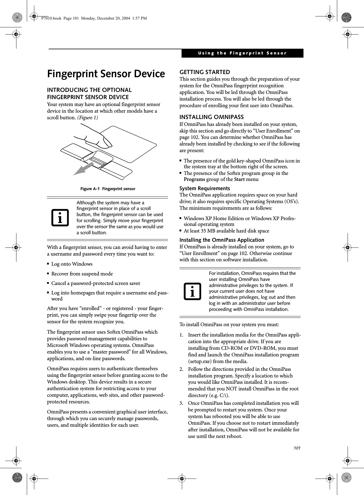
![102LifeBook P7000 Notebook – AppendixThe installation program automatically places an icon (Softex OmniPass) in the Windows Control Panel as well as a golden key shaped icon in the taskbar. Verifying Information about OmniPassAfter you have completed installing OmniPass and restarted your system, you may wish to check the version of OmniPass on your system.To check the version information of OmniPass:1. From the Windows Desktop, double-click the key-shaped OmniPass icon in the taskbar (usually located in the lower right corner of the screen),or,Click the Start button, select Settings, and click Control Panel (if you are using Windows XP you will see the Control Panel directly in the Start menu; click it, then click Switch to Classic View). Double-click Softex OmniPass in the Control Panel, and the OmniPass Control Center will appear. If it does not appear, then the program is not properly installed,or,Click the Start button, select Programs, and from the submenu select the Softex program group, from that submenu click OmniPass Control Center.2. Select the About tab at the top of the OmniPass Control Panel. The About tab window appears with version information about OmniPass.Uninstalling OmniPassTo remove the OmniPass application from your system:1. Click Start on the Windows taskbar. Select Settings, and then Control Panel.2. Double-click Add/Remove Programs.3. Select OmniPass, and then click Change/Remove.4. Follow the directions to uninstall the OmniPass application.5. Once OmniPass has finished uninstalling, reboot your system when prompted.USER ENROLLMENTBefore you can use any OmniPass features you must first enroll a user into OmniPass.Master Password ConceptComputer resources are often protected with passwords. Whether you are logging into your computer, accessing your email, e-banking, paying bills online, or accessing network resources, you often have to supply credentials to gain access. This can result in dozens of sets of creden-tials that you have to remember.During OmniPass user enrollment a "master password” is created for the enrolled user. This master password “replaces” all other passwords for sites you register with OmniPass. Example: A user, John, installs OmniPass on his system (his home computer) and enrolls an OmniPass user with username “John_01” and password “freq14”. He then goes to his webmail site to log onto his account. He inputs his webmail credentials as usual (username “John_02” and password “lifebook”), but instead of clicking [Submit], he directs OmniPass to Remember Password. Now whenever he returns to that site, OmniPass will prompt him to supply access credentials. John enters his OmniPass user credentials (“John_01” and “freq14”) in the OmniPass authentication prompt, and he is allowed into his webmail account. He can do this with as many web sites or password protected resources he likes, and he will gain access to all those sites with his OmniPass user credentials (“John_01” and “freq14”). This is assuming he is accessing those sites with the system onto which he enrolled his OmniPass user. OmniPass does not actually change the credentials of the password protected resource. If John were to go to an Internet cafe to access his webmail, he would need to enter his original webmail credentials (“John_02” and “lifebook”) to gain access. If he attempts his OmniPass user credentials on a system other than where he enrolled that OmniPass user, he will not gain access.Basic EnrollmentThe Enrollment Wizard will guide you through the process of enrolling a user. Unless you specified other-wise, after OmniPass installation the Enrollment Wizard will launch on Windows login. If you do not see the Enrollment Wizard, you can bring it up by clicking Start on the Windows taskbar; select Programs; select Softex; click OmniPass Enrollment Wizard.1. Click Enroll to proceed to username and password verification. By default, the OmniPass Enrollment Wizard enters the credentials of the currently logged in Windows user.2. Enter the password you use to log in to Windows. This will become the “master password” for this OmniPass user. In most cases, the Domain: value For uninstallation, OmniPass requires that the user uninstalling OmniPass have administrative privileges to the system. If your current user does not have administrative privileges, log out and then log in with an administrator user before proceeding with OmniPass uninstallation.The enrollment procedure assumes you have no hardware authentication devices or alternate storage locations that you wish to integrate with OmniPass. If you desire such functionality, consult the appropriate sections of this document.P7010.book Page 102 Monday, December 20, 2004 1:57 PM](https://usermanual.wiki/Fujitsu-Client-Computing/WL0033.Users-Manual/User-Guide-552678-Page-110.png)
![103Using the Fingerprint Sensorwill be your Windows computer name. In a corpo-rate environment, or when accessing corporate resources, the Domain: may not be your Windows computer name. Click [Next] to continue.3. In this step OmniPass captures your fingerprint. Refer to “Enrolling a Fingerprint” on page 103 for additional information.4. Next, choose how OmniPass notifies you of various events. We recommend you keep Taskbar Tips on Beginner mode taskbar tips and Audio Tips on at least Prompt with system beeps only until you get accustomed to how OmniPass operates. Click [Next] to proceed with user enrollment. You will then see a Congratulations screen indicating your completion of user enrollment.5. Click [Done] to exit the OmniPass Enrollment Wizard. You will be asked if you’d like to log in to OmniPass with your newly enrolled user; click [Yes].Enrolling a FingerprintEnrolling a fingerprint will increase the security of your system and streamline the authentication procedure. You enroll fingerprints in the OmniPass Control Center. With an OmniPass user logged in, double-click the system tray OmniPass icon. Select the User Settings tab and click Enrollment under the User Settings area. Click Enroll Authentication Device and authenticate at the authentication prompt to start device enrollment.1. During initial user enrollment, you will be prompted to select the finger you wish to enroll. Fingers that have already been enrolled will be marked by a green check. The finger you select to enroll at this time will be marked by a red arrow. OmniPass will allow you re-enroll a finger. If you choose a finger that has already been enrolled and continue enrollment, OmniPass will enroll the fingerprint, overwriting the old fingerprint. Select a finger to enroll and click [Next].2. It is now time for OmniPass to capture your selected fingerprint. It may take a several capture attempts before OmniPass acquires your fingerprint. Should OmniPass fail to acquire your fingerprint, or if the capture screen times out, click [Back] to restart the fingerprint enrollment process. Your system has a “swipe” fingerprint sensor. A swipe sensor is small and resembles a skinny elon-gated rectangle. To capture a fingerprint, gently swipe or pull your fingertip over the sensor (starting at the second knuckle) towards yourself. Swiping too fast or too slow will result in a failed capture. The Choose Finger screen has a [Practice] button; click it to practice capturing your fingerprint. When you are comfortable with how your fingerprint is captured, proceed to enroll a finger.3. Once OmniPass has successfully acquired the finger-print, the Ver if y Fi n g e r p r i n t screen will automati-cally appear. To verify your enrolled fingerprint, place your fingertip on the sensor and hold it there as if you were having a fingerprint captured. Successful fingerprint verification will show a green fingerprint in the capture window and the text Ver i -fication Successful under the capture window.USING OMNIPASSYou are now ready to begin using OmniPass. Used regu-larly, OmniPass will streamline your authentications.Password ReplacementYou will often use the password replacement function. When you go to a restricted access website (e.g., your bank, your web-based email, online auction or payment sites), you are always prompted to enter your login credentials. OmniPass can detect these prompts and you can teach OmniPass your login credentials. The next time you go to that website, you can authenticate with your fingerprint to gain access.OmniPass Authentication ToolbarAfter installing OmniPass and restarting, you will notice a dialog you have not seen before at Windows Logon. This is the OmniPass Authentication Toolbar, and it is displayed whenever the OmniPass authentication system is invoked. The OmniPass authentication system may be invoked frequently: during Windows Logon, during OmniPass Logon, when unlocking your workstation, when resuming from standby or hibernate, when unlocking a password-enabled screensaver, during pass-word replacement for remembered site or application logins, and more. When you see this toolbar, OmniPass is prompting you to authenticate.The Logon Authentication window indicates what OmniPass-restricted function you are attempting. The icons in the lower left (fingerprint and key) show what authentication methods are available to you. Selected authentication methods are highlighted while unselected methods are not. When you click the icon for an unse-lected authentication method, the authentication prompt associated with that method is displayed.When prompted to authenticate, you must supply the appropriate credentials: an enrolled finger for the finger-print capture window or your master password for the master password prompt (the key icon).Remembering a PasswordOmniPass can remember any application, GUI, or pass-word protected resource that has a password prompt.Using the following procedure, you can store a set of credentials into OmniPass. These credentials will then be linked to your “master password” or fingerprint.P7010.book Page 103 Monday, December 20, 2004 1:57 PM](https://usermanual.wiki/Fujitsu-Client-Computing/WL0033.Users-Manual/User-Guide-552678-Page-111.png)
![104LifeBook P7000 Notebook – AppendixGo to a site that requires a login (username and pass-word), but do not log in yet. At the site login prompt, enter your username and password in the prompted fields, but do not enter the site (do not hit [Enter], [Submit], [OK], or Login). Right-click the OmniPass system tray icon and select Remember Password from the submenu. The Windows arrow cursor will change to a golden key OmniPass cursor. Click this OmniPass cursor in the login prompt area, but do not click the [Login] or [Submit] button.Associating a Friendly NameAfter clicking the OmniPass key cursor near the login prompt, OmniPass will prompt you to enter a “friendly name” for this site. You should enter something that reminds you of the website, the company, or the service you are logging into. In its secure database, OmniPass associates this friendly name with this website.Additional Settings for Remembering a SiteWhen OmniPass prompts you to enter a “friendly name” you also have the opportunity to set how OmniPass authenticates you to this site. There are three effective settings for how OmniPass handles a remembered site.The default setting is Automatically click the “OK” or “Submit” button for this password protected site once the user is authenticated. With this setting, each time you navigate to this site OmniPass will prompt you for your master password or fingerprint authentication device. Once you have authenticated with OmniPass, you will automatically be logged into the site. Less secure is the option to Automatically enter this password protected site when it is activated. Do not prompt for authentication. Check the upper box to get this setting, and each time you navigate to this site OmniPass will log you into the site without prompting you to authenticate.If you uncheck both boxes in Settings for this Password Site, OmniPass will prompt you for your master pass-word or fingerprint authentication device. Once you have authenticated with OmniPass your credentials will be filled in to the site login prompt, but you will have to click the website [OK], [Submit], or [Login] button to gain access to the site. Click Finish to complete the remember password proce-dure. The site location, the credentials to access the site, and the OmniPass authentication settings for the site are now stored in the OmniPass secure database. The OmniPass authentication settings (Settings for this Pass-word Site) can always be changed in Vault Management.Logging in to a Remembered SiteWhether or not OmniPass prompts you to authenticate when you return to a remembered site is determined by Settings for this Password Site and can be changed in Vault Management. The following cases are applicable to using OmniPass to login to: Windows, remembered web sites, and all other password protected resources.With Master PasswordOnce you return to a site you have remembered with OmniPass, you may be presented with a master pass-word prompt. Enter your master password and you will be allowed into the site.Logging into Windows with a Fingerprint DeviceWhen logging into Windows with a fingerprint device, the fingerprint capture window will now appear next to the Windows Login screen. Place your enrolled fingertip on the sensor to authenticate. You will be simultaneously logged into Windows and OmniPass. The capture window will also appear if you have used Ctrl-Alt-Del to lock a system, and the fingerprint device can be used to log back in as stated above.In Windows XP, your login options must be set either for classic login, or for fast user switching and logon screen to be enabled to use your fingerprint to log on to Windows. To change this go to Control Panel, select User Accounts and then click Change the way users log on or off. If your Windows screensaver is password protected, the fingerprint capture window will now appear next to screensaver password dialog during resume. You can authenticate to your screensaver pass-word prompt with your enrolled finger.Password ManagementOmniPass provides an interface that lets you manage your passwords. To access this GUI, double-click the OmniPass key in the system tray. Click Vaul t Manag e -ment; you will be prompted to authenticate. Once you gain access to Vault Management, click Manage Pass-words under Vault Settings. You will see the Manage Passwords interface, with a list of friendly names.This setting is more convenient in that whenever you go to a site remembered with this setting, you will bypass any authentication procedure and gain instant access to the site. But should you leave your system unattended with your OmniPass user logged in, anyone using your system can browse to your password protected sites and gain automatic access.If a machine is locked and OmniPass detects a different user logging back in with a fingerprint, the first user will be logged out and the second user logged in.P7010.book Page 104 Monday, December 20, 2004 1:57 PM](https://usermanual.wiki/Fujitsu-Client-Computing/WL0033.Users-Manual/User-Guide-552678-Page-112.png)
![105Using the Fingerprint SensorYou can view the credentials stored for any remembered website by highlighting the desired resource under Pass-word Protected Dialog and clicking Unmask Values. Should a password be reset, or an account expire, you can remove stored credentials from OmniPass. Highlight the desired resource under Password Protected Dialog and click Delete Page. You will be prompted to confirm the password deletion.The two check boxes in Manage Passwords govern whether OmniPass prompts you to authenticate or directly logs you into the remembered site.OmniPass will overwrite an old set of credentials for a website if you attempt to use Remember Password on an already remembered site. The exception to the above rule is the resetting of your Windows password. If your password is reset in Windows, then the next time you login to Windows, OmniPass will detect the password change and prompt you to “Update” or “Reconfirm” your password with OmniPass. Enter your new Windows password in the prompt(s) and click OK and your OmniPass "master password" will still be your Windows password.OmniPass User IdentitiesIdentities allow OmniPass users to have multiple accounts to the same site (e.g., bob@biblomail.com and boballen@biblomail.com). If OmniPass did not provide you identities, you would be limited to remembering one account per site.To create and manage identities, double-click the OmniPass key in the system tray. Click Vault Manage -ment; OmniPass will prompt you to authenticate. Once you gain access to Vault Management, click Manage Identities under Vault Settings. You can only manage the identities of the currently logged in OmniPass userTo add a new identity, click New Identity or double-click Click here to add a new identity. Name the new identity and click [OK], then click [Apply]. You can now switch to the new identity and start remembering passwords.To delete an identity, highlight the identity you want to delete and click [Delete Identity], then click [Apply].To set the default identity, highlight the identity you want as default and click [Set as Default]; click [Apply] to ensure the settings are saved. If you log in to OmniPass with a fingerprint device, you will automati-cally be logged in to the default identity for that OmniPass user. You can choose the identity with which you are logging in if you login using "master password".Choosing User Identity during LoginTo choose your identity during login, type your user-name in the User Name: field. Press [Tab] and see that the Domain: field self-populates. Click the Password: field to bring the cursor to it, and you will see the pull-down menu in the Identity: field. Select the identity you wish to login as and then click OK to login.Switch User IdentityTo switch identities at any time, right-click the OmniPass system tray icon and click Switch User Iden-tity from the submenu. The Switch Identity dialog will appear. Select the desired identity and then click OK.Identities and Password ManagementOn the Manage Passwords interface of the Va u l t Management tab of the OmniPass Control Center, there is a pull-down selection box labeled, Identity. This field lets you choose which identity you are managing pass-words for. When you select an identity here, only those password protected dialogs that are associated with that identity are shown. You can perform all the functions explained in “Password Management” on page 104.CONFIGURING OMNIPASSThis section gives an overview of both the Export/Import function and the OmniPass Control Center. Exporting and Importing UsersUsing the OmniPass Control Center, you can export and import users in and out of OmniPass. The export process backs up all remembered sites, credentials, and any enrolled fingerprints for an OmniPass user. All OmniPass data for a user is backed up to a single encrypted database file. During the import process, the Windows login of the exported user is required. If the proper credentials cannot be supplied, the user profile will not be imported. When you delete an identity, all of its associated remembered sites and password protected dialogs are lost.■You should periodically export your user profile and store it in a safe place. If anything happens to your system, you can import your OmniPass profile to a new system and have all your remem-bered settings and fingerprints instantly.■You don't forget the Windows login credentials when exporting. When you examine the importation, you are prompted for authentication. The credentials that will allow a user profile to be imported are the Windows login credentials of the exported user. They are the credentials that had to be submitted when the user profile was exported. You will need User Name, Password, and Domain.P7010.book Page 105 Monday, December 20, 2004 1:57 PM](https://usermanual.wiki/Fujitsu-Client-Computing/WL0033.Users-Manual/User-Guide-552678-Page-113.png)