Fujitsu Client Computing WL0033 LifeBook P Series w/WM3B2915ABG 11ABG WLAN User Manual P Series
Fujitsu Limited LifeBook P Series w/WM3B2915ABG 11ABG WLAN P Series
Contents
- 1. Users Manual
- 2. Revised Users Manual1
- 3. Revised Users Manual2
Revised Users Manual2


![88LifeBook P Series Notebook - Appendix ADeactivation using Atheros Client Utility software1. Click [Start] -> [Program Files] -> [Atheros] -> Atheros Client Utility.2. Choose Action and click Disable Radio.ACTIVATING THE WLAN DEVICEActivation of the WLAN device can be accomplished using the same methods as the deactivation process■Using the Wireless On/Off Switch■In Windows using the Atheros software See “Configu-ration Using Atheros Client Utility Software” on page 89.P Series.book Page 88 Wednesday, July 13, 2005 10:43 AM](https://usermanual.wiki/Fujitsu-Client-Computing/WL0033.Revised-Users-Manual2/User-Guide-564447-Page-26.png)
![89Wireless LAN User’s Guide Configuration of the WLAN DeviceThe optional WLAN device can be configured to estab-lish wireless network connectivity using the Atheros Client Utility software. The Atheros Client Utility soft-ware allows for multiple profile setups and supports automatic profile switching. Support for most industry standard security solutions, as well as Cisco Compatible Extensions (CCX), is contained in this software.FLOW OF OPERATIONS1. Activate the WLAN Device (See Activating the WLAN Device on page 88 for more information).2. Configure the Wireless Network Key parameters (See “Configuration Using Atheros Client Utility Software” on page 89 for more information).■Enter the network name (SSID)■Choose the appropriate WLAN architecture (Ad Hoc or Infrastructure)■Choose Authentication method: Open, Shared, WPA, or WPA-PSK■If using static WEP keys, enter static WEP key and choose key index. 3. Configure network settings■TCP/IP settings■Workgroup or Domain settings.CONFIGURATION USING ATHEROS CLIENT UTILITY SOFTWAREThis section explains the procedure to properly configure the WLAN device using the Atheros Client Utility. Pre-defined parameters will be required for this procedure. Please consult with your network adminis-trator for these parameters:Network Name: Also known as the SSIDNetwork Key (WEP): Required if using static WEP keys. Authentication Type: Open, Shared, WPA, or WPA-PSKProcedure1. Activate the WLAN device using either the Wireless On/Off Switch or the Atheros Client Utility2. Click [Start] -> Programs -> Atheros -> Atheros Client Utility.3. Click the Profile Management tab. 4. If this is your first time using this utility, highlight the profile [Default] and Click the [Modify] button, otherwise Click the [New] button. The Profile Management dialog displays. 5. From the General tab, enter a profile name in the Profile Name field. 6. Enter the network SSID, in the SSID1 field. If you wish to create a profile that can connect to up to 3 different wireless networks, SSID's can be entered in the SSID2 and SSID3 fields as well.7. Click the Security tab. 8. The Security tab allows for the configuration of the Security modes listed in the table below. Please select the radio button of the desired security mode. If these settings are not known to you, please consult with your network administrator for the correct settings. 9. Click [OK].10. Click the Advanced tab.11. The Advanced tab allows for the configuration of the options detailed in the table below.Field Name DescriptionWPA/WPA2 Enables the use of Wi-Fi Protected Access. Choosing WPA opens the WPA EAP drop-down menu. If these settings are not known to you, please consult with your network administrator for the correct settings. WPA/WPA2 Passphrase Enables WPA-Pre-Shared Key. Click on the Configure button to enter the WPA Passphrase. If these settings are not known to you, please consult with your network administrator for the correct settings. 802.1x Enables 802.1x security. If these settings are not known to you, please consult with your network administrator for the correct settings. Choosing this option opens the 802.1x EAP type drop-down menu.Pre-Shared Key Enables the use of pre-shared keys that are defined on both the access point and the station. This is where static WEP keys are entered. Click the Configure button to fill in the Define Pre-Shared Keys window.None No securityP Series.book Page 89 Wednesday, July 13, 2005 10:43 AM](https://usermanual.wiki/Fujitsu-Client-Computing/WL0033.Revised-Users-Manual2/User-Guide-564447-Page-27.png)
![90LifeBook P Series Notebook - Appendix A12. Click [OK].13. If the profile you just created does not activate immediately, click the Profile Management tab, highlight the desired Profile, and click Activate.14. Click [OK] to close the Atheros Client Utility.CONNECTION TO THE NETWORKThis section explains connection to the network.If there is an administrator of the network, contact the network administrator for data settings.Setting the networkPerform the “Setting TCP/IP” and “Confirming the computer and work group names” operations required for network connection.Setting TCP/IP1. Click the [Start] button first and then [Control Panel].2. If the Control Panel is in Category view, switch to Classic view by clicking “Switch to Classic View” under Control Panel the left frame. (If you are already in Classic view, “Switch to Category View” will be displayed.) 3. Double-click [Network Connections]. A list of cur-rently installed networks will be displayed.4. Right-click [Wireless Network Connection] in the list, and then click [Properties] in the menu dis-played. The [Wireless Network Connection Proper-ties] window will be displayed.5. Click the [General] tab if it is not already selected.6. Click [Internet Protocol (TCP/IP] and then click [Properties]. The [Internet Protocol (TCP/IP) Properties] window will be displayed.7. Set the IP address as follows:■For ad hoc connection: Select [Use the following IP address:] and then enter data for [IP address] and [Subnet mask]. See page 96 for IP address setting.■For access point (infrastructure) connection: If your network uses DHCP, select [Obtain an IP address automatically] and [Obtain DNS server address automatically]. If your network uses static IP addresses, consult with your network adminis-trator for the correct IP address settings.8. Click the [OK] button. Processing will return to the [Wireless Network Connection Properties] window.9. Click the [OK] button.10. Close the [Network Connection] window. Following this operation, confirm the names of the computer and the workgroup as follows.Confirming the computer and work group names1. Click the [Start] button, then [Control Panel].2. If the Control Panel is in Category view, switch to Classic view by clicking “Switch to Classic View” under Control Panel the left frame. (If you are already in Classic view, “Switch to Category View” will be displayed.) 3. Double-click the [System] icon. The [System Prop-erties] window will be displayed.4. Click the [Computer Name] tab.5. Confirm the settings of [Full computer name:] and [Workgroup:].a. The setting of [Full computer name:] denotes the name for identifying the computer. Any name can be assigned for each personal computer. Field Name DescriptionPower Save ModeOptions are Maximum, Normal, or OffNetwork Type Options are AP (Infrastructure) or Ad Hoc802.11b PreambleSpecifies the preamble setting in 802.11b. The default setting is Short and Long (Access Point mode), which allows both short and long headers in the 802.11b frames. Set to Long Only to override allowing short frames.Transmit Power LevelSelect the desired transmit power level from the dropdown list.Wireless Mode Specifies 5 GHz 54 Mbps, 2.4 GHz 11 Mbps, or 2.4 GHz 54 Mbps oper-ation in an access point network.Wireless Mode when Starting Ad Hoc NetworkSpecifies 5GHz 54 Mbps, 5 GHz 108 Mbps, or 2.4 GHz 11 Mbps to start an Ad Hoc network if no matching network name is found after scan-ning all available modes.To change the setting of the IP address, you need to be logged in from Windows as an administrator.To modify the computer name and/or the work group name, you need to be logged in from Windows as an administrator.P Series.book Page 90 Wednesday, July 13, 2005 10:43 AM](https://usermanual.wiki/Fujitsu-Client-Computing/WL0033.Revised-Users-Manual2/User-Guide-564447-Page-28.png)
![91Wireless LAN User’s Guide Enter the desired name in less than 15 ASCII character code format. Identifiability can be enhanced by entering the model number, the user name, and other factors.b. [Workgroup name] is the group name of the network. Enter the desired name in less than 15 ASCII character code format.For ad hoc connection: Assign the same network name to all personal computers existing on the network.For access point (infrastructure) connection: Assign the name of the work group to be accessed.6. Click the [OK] button. If a message is displayed that requests you to restart the personal computer, click [Yes] to restart the computer.Setting the sharing functionSet the sharing function to make file and/or printer sharing with other network-connected personal computers valid.This operation is not required unless the sharing func-tion is to be used.The folder and printer for which the sharing function has been set will be usable from any personal computer present on the network.Setting the Microsoft network-sharing service1. Click the [Start] button first and then [Control Panel]. 2. If the Control Panel is in Category view, switch to Classic view by clicking “Switch to Classic View” under Control Panel the left frame. (If you are already in Classic view, “Switch to Category View” will be displayed.) 3. Double-click [Network Connections]. A list of cur-rently installed networks will be displayed.4. Right-click [Wireless Network Connection] in the list, and then click [Properties] in the menu dis-played. The [Wireless Network Connection Proper-ties] window will be displayed.5. If [File and Printer Sharing for Microsoft Net-works] is displayed, proceed to step 6. If [File and Printer Sharing for Microsoft Networks] is not dis-played, skip to step 7.6. Make sure that the [File and Printer Sharing for Microsoft Networks] check box is checked, and then click the [OK] button. Skip to “Setting file-sharing function”.7. Click [Install]. The [Select Network Component Type] window will be displayed.8. Click [Service], then click the [Add] button. The [Select Network Service] window will be displayed.9. Click [File and Printer Sharing for Microsoft Net-works] and then click the [OK] button. Processing will return to the [Wireless Network Connection Properties] window, and [File and Printer Sharing for Microsoft Networks] will be added to the list.10. Click the [Close] button.Setting the file-sharing functionThe procedure for setting the file-sharing function follows, with the “work” folder in drive C: as an example.1. Double-click [My Computer] on the desktop. 2. Double-click [Local disk (C:)].3. Right-click the “work” folder (or whichever folder you want to share), and then click [Sharing and Security...] in the menu displayed. The [Folder Name Properties] window will be displayed.4. Click [Sharing] if it isn’t already selected.5. Click the link stating “If you understand the secu-rity risks, but want to share files without running the wizard, click here”.6. Click “Just enable file sharing” and click [OK].7. Check the [Share this folder on the network] check box.To change the name, click [Change] and then proceed in accordance with the instruction messages displayed on the screen.To share a file and/or the connected printer, you need to be logged in as an administrator.Setting the file-sharing function for the file which has been used to execute Network Setup Wizard is suggested on the screen. For the wireless LAN, however, since security is guaranteed by entry of the network name (SSID) and the network key, the steps to be taken to set the file-sharing function easily without using Network Setup Wizard are given below.P Series.book Page 91 Wednesday, July 13, 2005 10:43 AM](https://usermanual.wiki/Fujitsu-Client-Computing/WL0033.Revised-Users-Manual2/User-Guide-564447-Page-29.png)
![92LifeBook P Series Notebook - Appendix A8. Click the [OK] button. The folder will be set as a sharable folder, and the display of the icon for the “work” folder will change.Setting the printer-sharing function1. Click [Start] -> Settings and then [Printers and Faxes]. A list of connected printers will be dis-played.2. Right-click the printer for which the sharing func-tion is to be set, and then click [Sharing] in the menu displayed. The property window correspond-ing to the selected printer will be displayed.3. Click the [Sharing] tab.4. Click [Share this printer].5. Enter the sharing printer name in [Share name].6. Click the [OK] button. Confirming connectionAfter you have finished the network setup operations, access the folder whose sharing has been set for other personal computers. Also, confirm the status of the radio waves in case of trouble such as a network connection failure.Connecting your personal computer to another personal computer1. Click [Start] first and then [My Computer]. The [My Computer] window will be displayed in the left frame.2. Click [My Network Places] in the “Other Places” list. The window [My Network Places] will be dis-played.3. Click [View workgroup computers] under Network Tasks in the left frame.4. Double-click the personal computer to which your personal computer is to be connected. The folder that was specified in “Setting the file-sharing func-tion” on page 91 will be displayed.5. Double-click the folder to be accessed.Confirming the status of the radio1. Right-click the Atheros icon in the lower right cor-ner of the screen.2. Click [Open Atheros Client Utility]. The Atheros Client Utility window opens.3. Contained within the Current Status and Profile Management tabs, you will find the current operat-ing status of the radio. (When the radio is turned off or the computer is not yet connected, some of the conditions will not be displayed.)Among the information displayed are the follow-ing:■Network Name (SSID)Displays the Network Name (SSID) currently used by the radio.■Profile NameThe current configuration profile is displayed.■ModeDisplays the current operating mode. [Infra-structure (AP)] or [Ad Hoc] will be displayed.■Data EncryptionDisplays the current security status of the profile being used:None: No encryption used.WEP: WEP encryption algorithm used.CKIP: WEP encryption algorithm used.TKIP: WEP encryption algorithm used.■Signal StrengthDisplays the current strength of the signal being received by the radio.■Current ChannelDisplays the current transmit and receive channel being used.■Radio StatusDisplays the current status of the radio.To specify the corresponding folder as a read-only folder, select the [Read only] checkbox under the General tab.Setting the printer-sharing function when Network Setup Wizard has been executed is suggested on the screen. For the wireless LAN, however, since security is guaranteed by entry of the network name (SSID) and the network key, the steps to be taken to set the printer-sharing function without using Network Setup Wizard are laid down below.In the case of access point (infrastructure) connection, enter the necessary data for the access point before confirming connection. Refer to the manual of the access point for the access point setup procedure.P Series.book Page 92 Wednesday, July 13, 2005 10:43 AM](https://usermanual.wiki/Fujitsu-Client-Computing/WL0033.Revised-Users-Manual2/User-Guide-564447-Page-30.png)
![96LifeBook P Series Notebook - Appendix AIP address informationABOUT IP ADDRESSESIf IP address is unknown, set IP address as follows, or,If you have an access point (DHCP server) on the network, set the IP address as follows:[Obtain an IP address automatically]If the IP address is already assigned to the computer in the network, ask the network administrator to check the IP address to be set for the computer.If no access point is found in the network:An IP address is expressed with four values in the range between 1 and 255.Set the each computer as follows: The value in paren-theses is a subnet mask.<Example>Computer A: 192.168.100.2 (255.255.255.0)Computer B: 192.168.100.3 (255.255.255.0)Computer C: 192.168.100.4 (255.255.255.0)::Computer X: 192.168.100.254 (255.255.255.0)IP addressing is much more complicated than can be briefly explained in this document. You are advised to consult with your network administrator for additional information.A DHCP server is a server that automatically assigns IP addresses to computers or other devices in the network. There is no DHCP server for the AdHoc network.P Series.book Page 96 Wednesday, July 13, 2005 10:43 AM](https://usermanual.wiki/Fujitsu-Client-Computing/WL0033.Revised-Users-Manual2/User-Guide-564447-Page-34.png)


![102LifeBook T Series Tablet PC - Appendix BVerifying Information about OmniPassAfter you have completed installing OmniPass and restarted your system, you may wish to check the version of OmniPass on your system.To check the version information of OmniPass:1. From the Windows Desktop, double-click the key-shaped OmniPass icon in the taskbar (usually located in the lower right corner of the screen),or,Click the Start button, select Settings, and click Control Panel (if you are using Windows XP you will see the Control Panel directly in the Start menu; click it, then click Switch to Classic View). Double-click Softex OmniPass in the Control Panel, and the OmniPass Control Center will appear. If it does not appear, then the program is not properly installed,or,Click the Start button, select Programs, and from the submenu select the Softex program group, from that submenu click OmniPass Control Center.2. Select the About tab at the top of the OmniPass Control Panel. The About tab window appears with version information about OmniPass.Uninstalling OmniPassTo remove the OmniPass application from your system:1. Click Start on the Windows taskbar. Select Settings, and then Control Panel.2. Double-click Add/Remove Programs.3. Select OmniPass, and then click Change/Remove.4. Follow the directions to uninstall the OmniPass application.5. Once OmniPass has finished uninstalling, reboot your system when prompted.USER ENROLLMENTBefore you can use any OmniPass features you must first enroll a user into OmniPass.Master Password ConceptComputer resources are often protected with passwords. Whether you are logging into your computer, accessing your email, e-banking, paying bills online, or accessing network resources, you often have to supply credentials to gain access. This can result in dozens of sets of creden-tials that you have to remember.During OmniPass user enrollment a "master password” is created for the enrolled user. This master password “replaces” all other passwords for sites you register with OmniPass. Example: A user, John, installs OmniPass on his system (his home computer) and enrolls an OmniPass user with username “John_01” and password “freq14”. He then goes to his webmail site to log onto his account. He inputs his webmail credentials as usual (username “John_02” and password “tablet”), but instead of clicking [Submit], he directs OmniPass to Remember Password. Now whenever he returns to that site, OmniPass will prompt him to supply access credentials. John enters his OmniPass user credentials (“John_01” and “freq14”) in the OmniPass authentication prompt, and he is allowed into his webmail account. He can do this with as many web sites or password protected resources he likes, and he will gain access to all those sites with his OmniPass user credentials (“John_01” and “freq14”). This is assuming he is accessing those sites with the system onto which he enrolled his OmniPass user. OmniPass does not actually change the credentials of the password protected resource. If John were to go to an Internet cafe to access his webmail, he would need to enter his original webmail credentials (“John_02” and “tablet”) to gain access. If he attempts his OmniPass user credentials on a system other than where he enrolled that OmniPass user, he will not gain access.Basic EnrollmentThe Enrollment Wizard will guide you through the process of enrolling a user. Unless you specified other-wise, after OmniPass installation the Enrollment Wizard will launch on Windows login. If you do not see the Enrollment Wizard, you can bring it up by clicking Start on the Windows taskbar; select Programs; select Softex; click OmniPass Enrollment Wizard.1. Click Enroll to proceed to username and password verification. By default, the OmniPass Enrollment Wizard enters the credentials of the currently logged in Windows user.2. Enter the password you use to log in to Windows. This will become the “master password” for this OmniPass user. In most cases, the Domain: value For uninstallation, OmniPass requires that the user uninstalling OmniPass have administrative privileges to the system. If your current user does not have administrative privileges, log out and then log in with an administrator user before proceeding with OmniPass uninstallation.The basic enrollment procedure assumes you have no hardware authentication devices or alternate storage locations that you wish to integrate with OmniPass. If you desire such functionality, consult the appropriate sections after reviewing this section.P Series.book Page 102 Wednesday, July 13, 2005 10:43 AM](https://usermanual.wiki/Fujitsu-Client-Computing/WL0033.Revised-Users-Manual2/User-Guide-564447-Page-40.png)
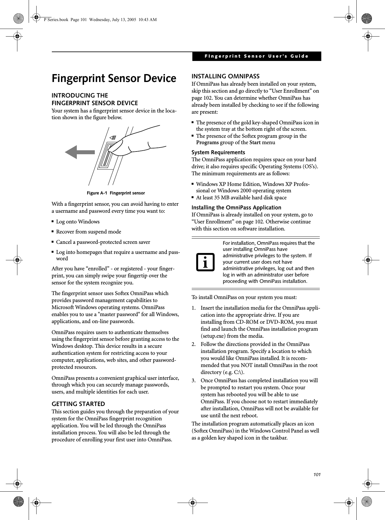
![103FIngerprint Sensor User’s Guide will be your Windows computer name. In a corpo-rate environment, or when accessing corporate resources, the Domain: may not be your Windows computer name. Click [Next] to continue.3. In this step OmniPass captures your fingerprint. Refer to “Enrolling a Fingerprint” on page 103 for additional information.4. Next, choose how OmniPass notifies you of various events. We recommend you keep Taskbar Tips on Beginner mode taskbar tips and Audio Tips on at least Prompt with system beeps only until you get accustomed to how OmniPass operates. Click [Next] to proceed with user enrollment. You will then see a Congratulations screen indicating your completion of user enrollment.5. Click [Done] to exit the OmniPass Enrollment Wizard. You will be asked if you’d like to log in to OmniPass with your newly enrolled user; click [Yes].Enrolling a FingerprintEnrolling a fingerprint will increase the security of your system and streamline the authentication procedure. You enroll fingerprints in the OmniPass Control Center. With an OmniPass user logged in, double-click the system tray OmniPass icon. Select the User Settings tab and click Enrollment under the User Settings area. Click Enroll Authentication Device and authenticate at the authentication prompt to start device enrollment.1. During initial user enrollment, you will be prompted to select the finger you wish to enroll. Fingers that have already been enrolled will be marked by a green check. The finger you select to enroll at this time will be marked by a red arrow. OmniPass will allow you re-enroll a finger. If you choose a finger that has already been enrolled and continue enrollment, OmniPass will enroll the fingerprint, overwriting the old fingerprint. Select a finger to enroll and click [Next].2. It is now time for OmniPass to capture your selected fingerprint. It may take a several capture attempts before OmniPass acquires your fingerprint. Should OmniPass fail to acquire your fingerprint, or if the capture screen times out, click [Back] to restart the fingerprint enrollment process. Your system has a “swipe” fingerprint sensor. A swipe sensor is small and resembles a skinny elon-gated rectangle. To capture a fingerprint, gently swipe or pull your fingertip over the sensor (starting at the second knuckle) towards yourself. Swiping too fast or too slow will result in a failed capture. The Choose Finger screen has a [Practice] button; click it to practice capturing your fingerprint. When you are comfortable with how your fingerprint is captured, proceed to enroll a finger.3. Once OmniPass has successfully acquired the finger-print, the Ver if y F i n g er p r i nt screen will automati-cally appear. To verify your enrolled fingerprint, place your fingertip on the sensor and hold it there as if you were having a fingerprint captured. Successful fingerprint verification will show a green fingerprint in the capture window and the text Ver i -fication Successful under the capture window.USING OMNIPASSYou are now ready to begin using OmniPass. Used regularly, OmniPass will streamline your authentication procedures.Password ReplacementYou will often use the password replacement function. When you go to a restricted access website (e.g., your bank, your web-based email, online auction or payment sites), you are always prompted to enter your login credentials. OmniPass can detect these prompts and you can teach OmniPass your login credentials. The next time you go to that website, you can authenticate with your fingerprint to gain access.OmniPass Authentication ToolbarAfter installing OmniPass and restarting, you will notice a dialog you have not seen before at Windows Logon. This is the OmniPass Authentication Toolbar, and it is displayed whenever the OmniPass authentication system is invoked. The OmniPass authentication system may be invoked frequently: during Windows Logon, during OmniPass Logon, when unlocking your workstation, when resuming from standby or hibernate, when unlocking a password-enabled screensaver, during pass-word replacement for remembered site or application logins, and more. When you see this toolbar, OmniPass is prompting you to authenticate.The Logon Authentication window indicates what OmniPass-restricted function you are attempting. The icons in the lower left (fingerprint and key) show what authentication methods are available to you. Selected authentication methods are highlighted while unselected methods are not. When you click the icon for an unse-lected authentication method, the authentication prompt associated with that method is displayed.When prompted to authenticate, you must supply the appropriate credentials: an enrolled finger for the finger-print capture window or your master password for the master password prompt (the key icon).Remembering a PasswordOmniPass can remember any application, GUI, or pass-word protected resource that has a password prompt.Using the following procedure, you can store a set of credentials into OmniPass. These credentials will then be linked to your “master password” or fingerprint.P Series.book Page 103 Wednesday, July 13, 2005 10:43 AM](https://usermanual.wiki/Fujitsu-Client-Computing/WL0033.Revised-Users-Manual2/User-Guide-564447-Page-41.png)
![104LifeBook T Series Tablet PC - Appendix BGo to a site that requires a login (username and pass-word), but do not log in yet. At the site login prompt, enter your username and password in the prompted fields, but do not enter the site (do not hit [Enter], [Submit], [OK], or Login). Right-click the OmniPass system tray icon and select Remember Password from the submenu. The Windows arrow cursor will change to a golden key OmniPass cursor. Click this OmniPass cursor in the login prompt area, but do not click the [Login] or [Submit] button.Associating a Friendly NameAfter clicking the OmniPass key cursor near the login prompt, OmniPass will prompt you to enter a “friendly name” for this site. You should enter something that reminds you of the website, the company, or the service you are logging into. In its secure database, OmniPass associates this friendly name with this website.Additional Settings for Remembering a SiteWhen OmniPass prompts you to enter a “friendly name” you also have the opportunity to set how OmniPass authenticates you to this site. There are three effective settings for how OmniPass handles a remembered site.The default setting is Automatically click the “OK” or “Submit” button for this password protected site once the user is authenticated. With this setting, each time you navigate to this site OmniPass will prompt you for your master password or fingerprint authentication device. Once you have authenticated with OmniPass, you will automatically be logged into the site. Less secure is the option to Automatically enter this password protected site when it is activated. Do not prompt for authentication. Check the upper box to get this setting, and each time you navigate to this site OmniPass will log you into the site without prompting you to authenticate.If you uncheck both boxes in Settings for this Password Site, OmniPass will prompt you for your master pass-word or fingerprint authentication device. Once you have authenticated with OmniPass your credentials will be filled in to the site login prompt, but you will have to click the website [OK], [Submit], or [Login] button to gain access to the site. Click Finish to complete the remember password proce-dure. The site location, the credentials to access the site, and the OmniPass authentication settings for the site are now stored in the OmniPass secure database. The OmniPass authentication settings (Settings for this Pass-word Site) can always be changed in Vault Management.Logging in to a Remembered SiteWhether or not OmniPass prompts you to authenticate when you return to a remembered site is determined by Settings for this Password Site and can be changed in Vault Management. The following cases are applicable to using OmniPass to login to: Windows, remembered web sites, and all other password protected resources.With Master PasswordOnce you return to a site you have remembered with OmniPass, you may be presented with a master pass-word prompt. Enter your master password and you will be allowed into the site.Logging into Windows with a Fingerprint DeviceWhen logging into Windows with a fingerprint device, the fingerprint capture window will now appear next to the Windows Login screen. Place your enrolled fingertip on the sensor to authenticate. You will be simultaneously logged into Windows and OmniPass. The capture window will also appear if you have used Ctrl-Alt-Del to lock a system, and the fingerprint device can be used to log back in as stated above.In Windows XP, your login options must be set either for classic login, or for fast user switching and logon screen to be enabled to use your fingerprint to log on to Windows. To change this go to Control Panel, select User Accounts and then click Change the way users log on or off. If your Windows screensaver is password protected, the fingerprint capture window will now appear next to screensaver password dialog during resume. You can authenticate to your screensaver pass-word prompt with your enrolled finger.Password ManagementOmniPass provides an interface that lets you manage your passwords. To access this GUI, double-click the OmniPass key in the system tray. Click Vaul t Manag e-ment; you will be prompted to authenticate. Once you gain access to Vault Management, click Manage Pass-words under Vault Settings. You will see the Manage Passwords interface, with a list of friendly names.This setting is more convenient in that whenever you go to a site remembered with this setting, you will bypass any authentication procedure and gain instant access to the site. But should you leave your system unattended with your OmniPass user logged in, anyone using your system can browse to your password protected sites and gain automatic access.If a machine is locked and OmniPass detects a different user logging back in with a fingerprint, the first user will be logged out and the second user logged in.P Series.book Page 104 Wednesday, July 13, 2005 10:43 AM](https://usermanual.wiki/Fujitsu-Client-Computing/WL0033.Revised-Users-Manual2/User-Guide-564447-Page-42.png)
![105FIngerprint Sensor User’s Guide You can view the credentials stored for any remembered website by highlighting the desired resource under Pass-word Protected Dialog and clicking Unmask Values. Should a password be reset, or an account expire, you can remove stored credentials from OmniPass. Highlight the desired resource under Password Protected Dialog and click Delete Page. You will be prompted to confirm the password deletion.The two check boxes in Manage Passwords govern whether OmniPass prompts you to authenticate or directly logs you into the remembered site.OmniPass will overwrite an old set of credentials for a website if you attempt to use Remember Password on an already remembered site. The exception to the above rule is the resetting of your Windows password. If your password is reset in Windows, then the next time you login to Windows, OmniPass will detect the password change and prompt you to “Update” or “Reconfirm” your password with OmniPass. Enter your new Windows password in the prompt(s) and click OK and your OmniPass "master password" will still be your Windows password.OmniPass User IdentitiesIdentities allow OmniPass users to have multiple accounts to the same site (e.g., bob@biblomail.com and boballen@biblomail.com). If OmniPass did not provide you identities, you would be limited to remembering one account per site.To create and manage identities, double-click the OmniPass key in the system tray. Click Vault Mana g e -ment; OmniPass will prompt you to authenticate. Once you gain access to Vault Management, click Manage Identities under Vault Settings. You can only manage the identities of the currently logged in OmniPass userTo add a new identity, click New Identity or double-click Click here to add a new identity. Name the new identity and click [OK], then click [Apply]. You can now switch to the new identity and start remembering passwords.To delete an identity, highlight the identity you want to delete and click [Delete Identity], then click [Apply].To set the default identity, highlight the identity you want as default and click [Set as Default]; click [Apply] to ensure the settings are saved. If you log in to OmniPass with a fingerprint device, you will automati-cally be logged in to the default identity for that OmniPass user. You can choose the identity with which you are logging in if you login using "master password".Choosing User Identity during LoginTo choose your identity during login, type your user-name in the User Name: field. Press [Tab] and see that the Domain: field self-populates. Click the Password: field to bring the cursor to it, and you will see the pull-down menu in the Identity: field. Select the identity you wish to login as and then click OK to login.Switch User IdentityTo switch identities at any time, right-click the OmniPass system tray icon and click Switch User Iden-tity from the submenu. The Switch Identity dialog will appear. Select the desired identity and then click OK.Identities and Password ManagementOn the Manage Passwords interface of the Vau l t Management tab of the OmniPass Control Center, there is a pull-down selection box labeled, Identity. This field lets you choose which identity you are managing pass-words for. When you select an identity here, only those password protected dialogs that are associated with that identity are shown. You can perform all the functions explained in “Password Management” on page 104.CONFIGURING OMNIPASSThis section gives an overview of both the Export/Import function and the OmniPass Control Center. Exporting and Importing UsersUsing the OmniPass Control Center, you can export and import users in and out of OmniPass. The export process backs up all remembered sites, credentials, and any enrolled fingerprints for an OmniPass user. All OmniPass data for a user is backed up to a single encrypted database file. During the import process, the Windows login of the exported user is required. If the proper credentials cannot be supplied, the user profile will not be imported. When you delete an identity, all of its associated remembered sites and password protected dialogs are lost.■You should periodically export your user profile and store it in a safe place. If anything happens to your system, you can import your OmniPass profile to a new system and have all your remem-bered settings and fingerprints instantly.■You don't forget the Windows login credentials when exporting. When you examine the importation, you are prompted for authentication. The credentials that will allow a user profile to be imported are the Windows login credentials of the exported user. They are the credentials that had to be submitted when the user profile was exported. You will need User Name, Password, and Domain.P Series.book Page 105 Wednesday, July 13, 2005 10:43 AM](https://usermanual.wiki/Fujitsu-Client-Computing/WL0033.Revised-Users-Manual2/User-Guide-564447-Page-43.png)