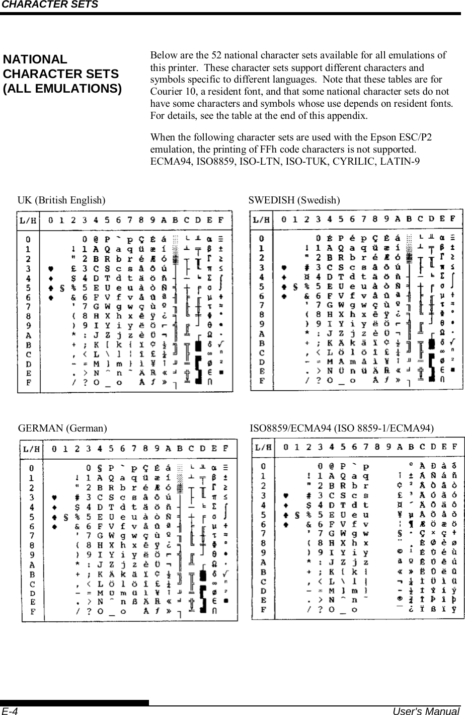
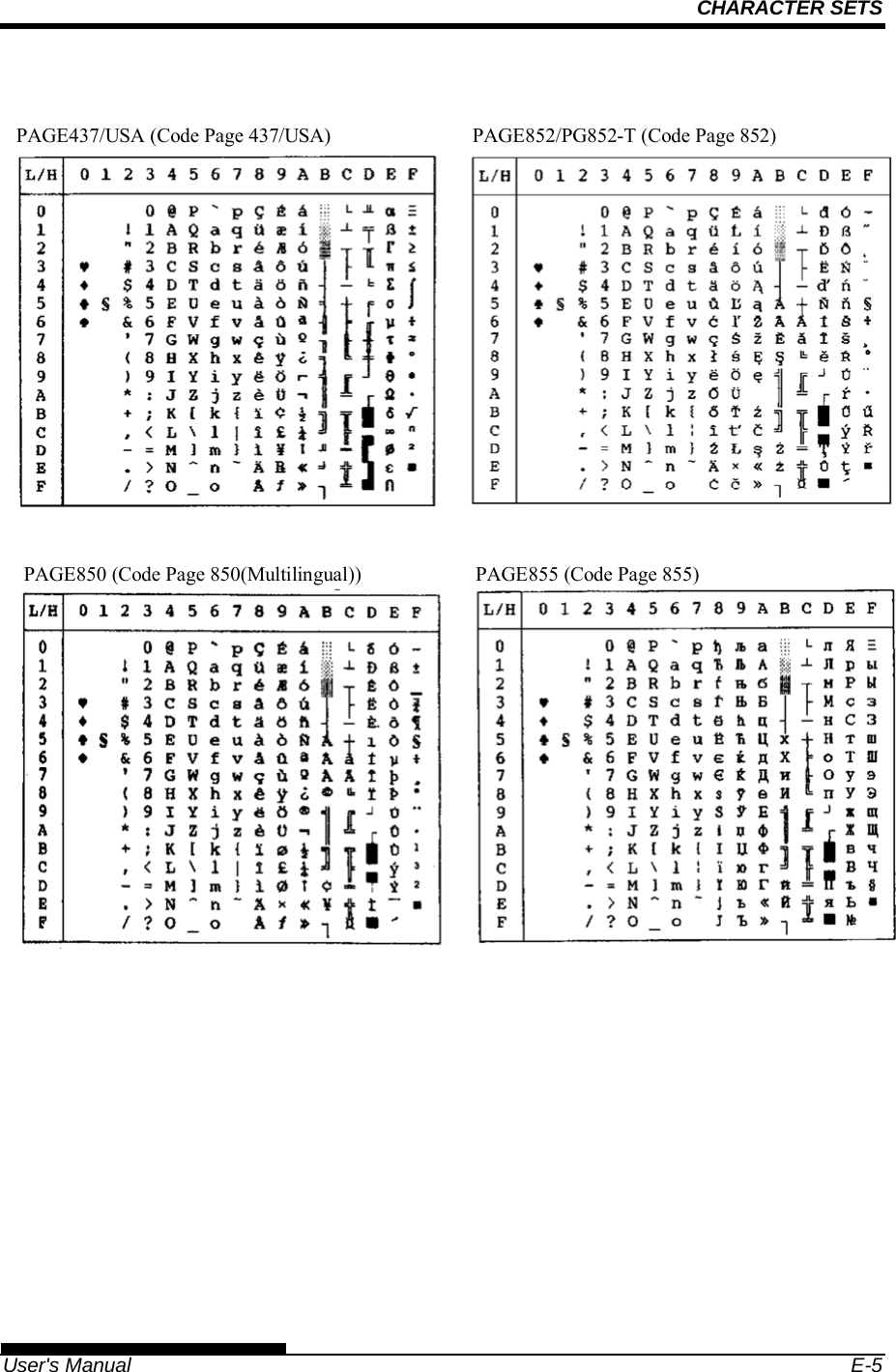
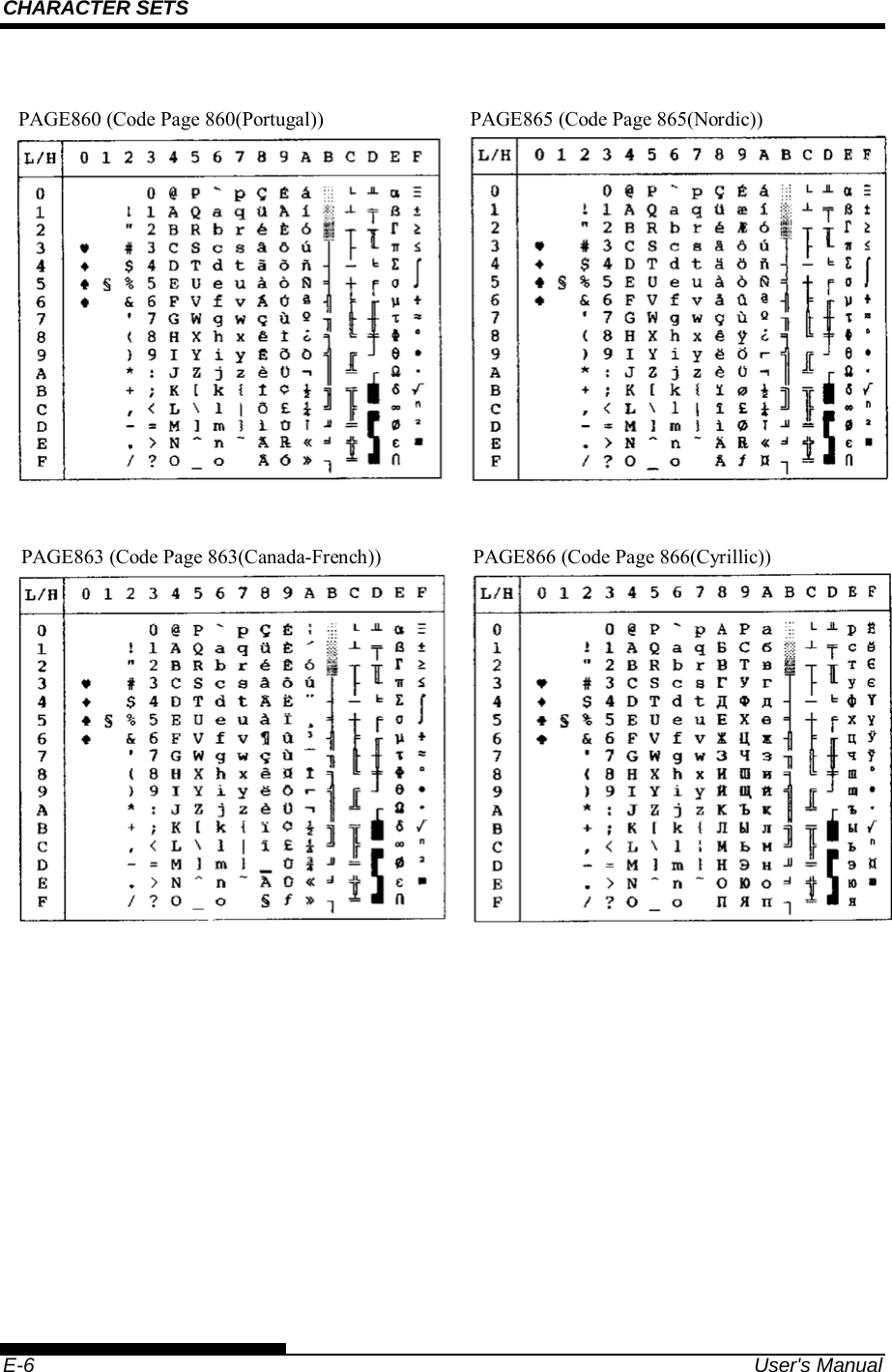
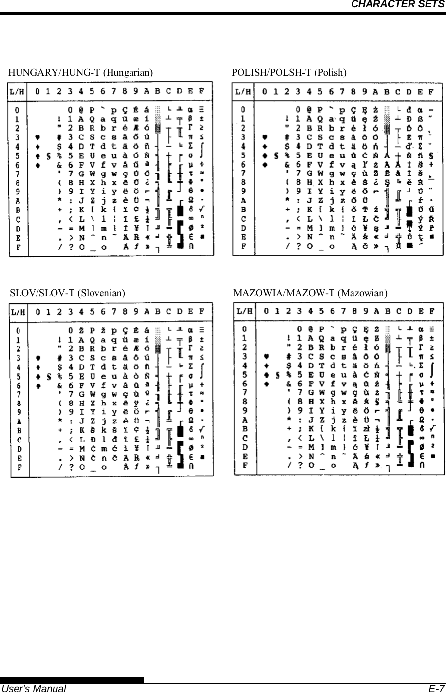
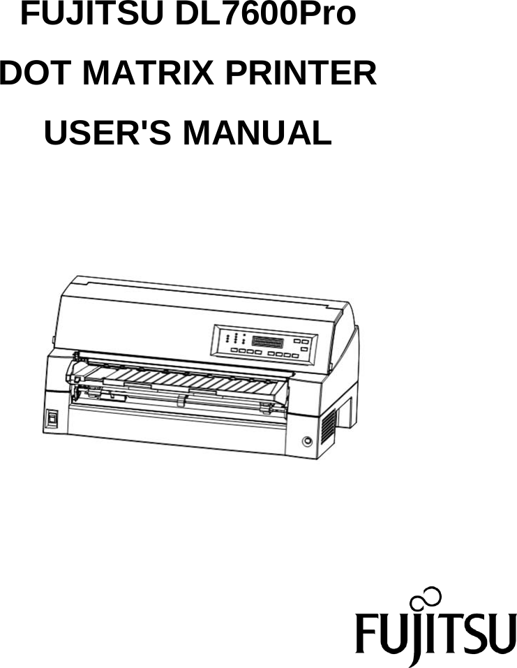
Fujitsu Isotec 020M33335A Dot Matrix Printer User Manual
Fujitsu Isotec Limited Dot Matrix Printer
UserManual.wiki
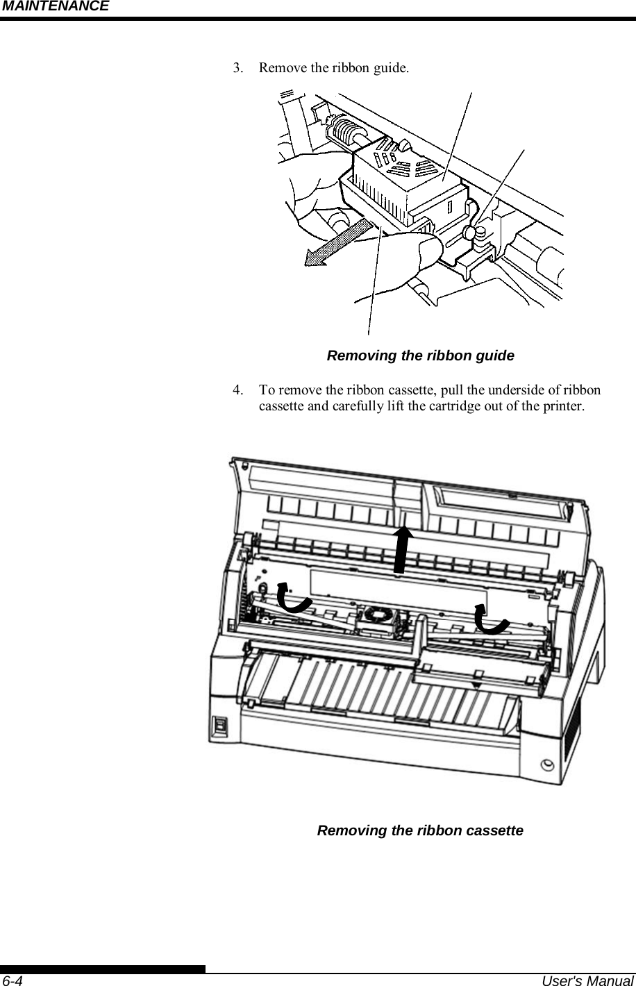
>
Fujitsu Isotec
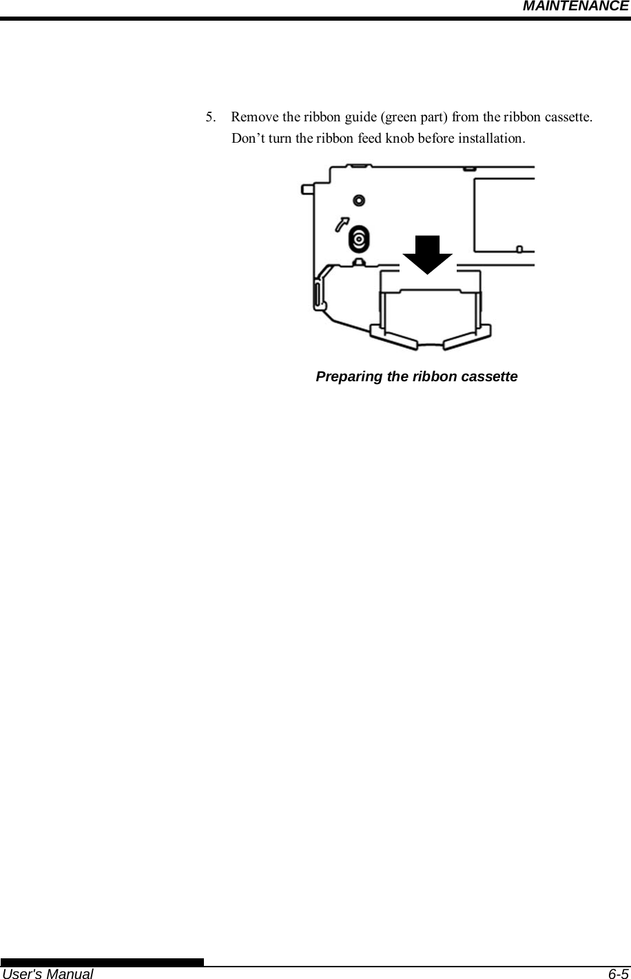
>
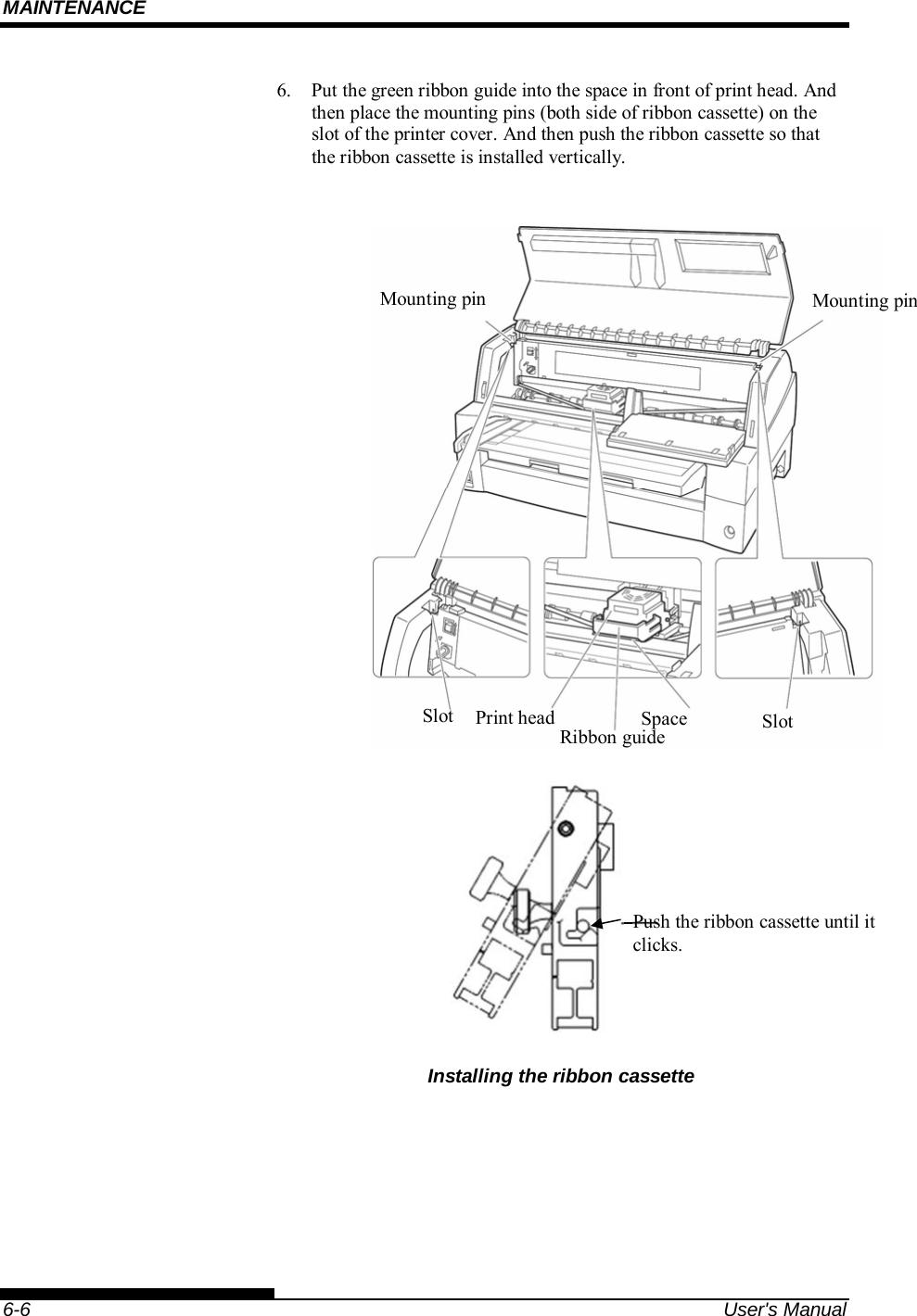
020M33335A User Manual
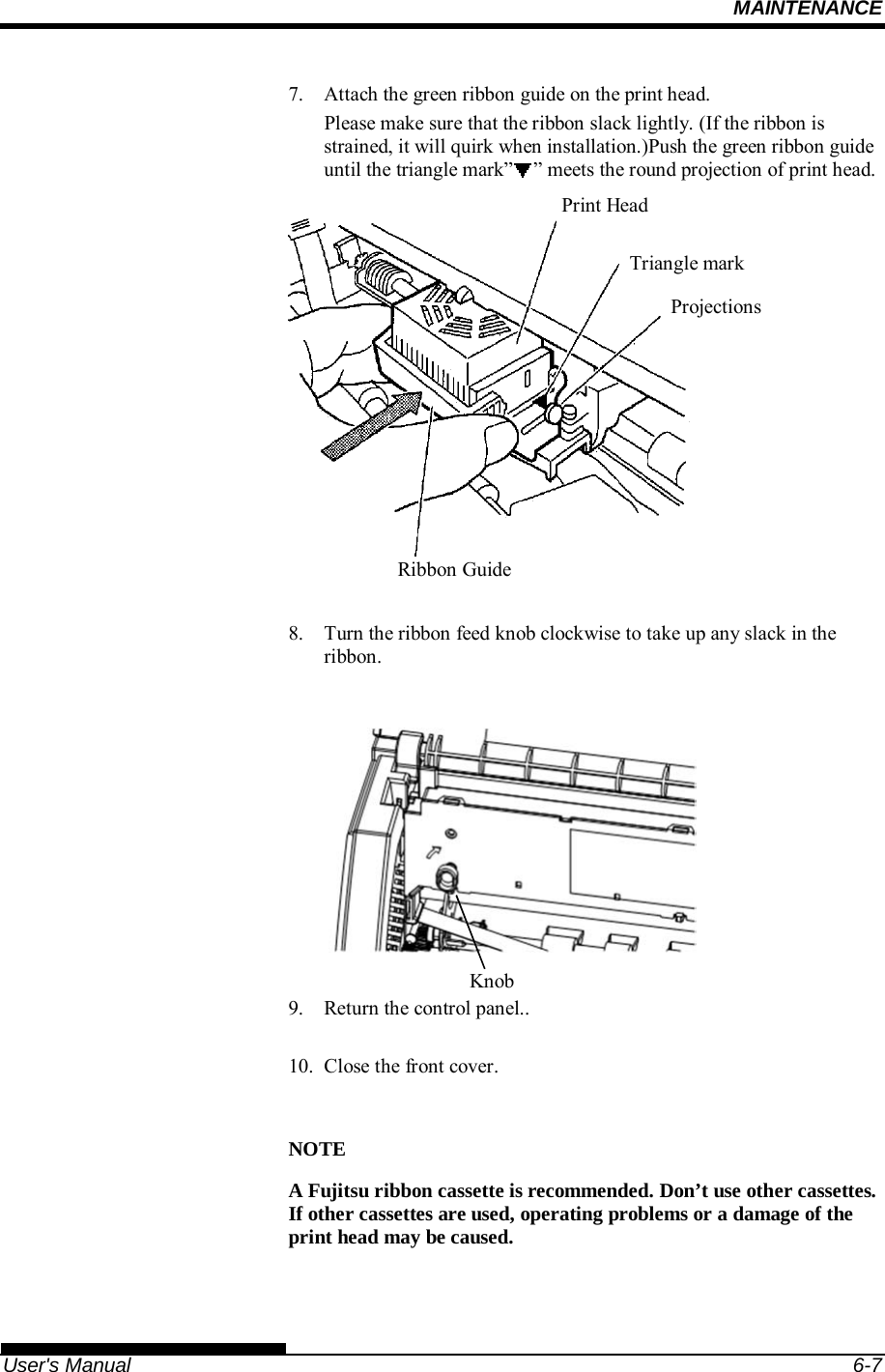
User Manual
Navigation menu
Upload a User Manual
Namespaces
Wiki Guide
HTML
PDF
Info
Views
User Manual
Discussion / Help
Navigation

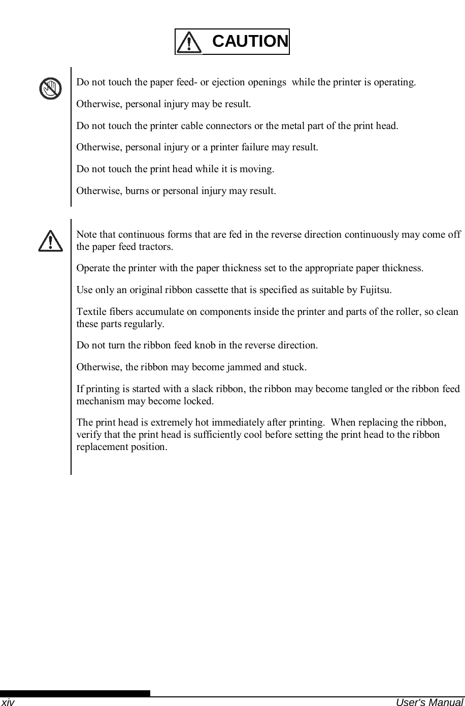
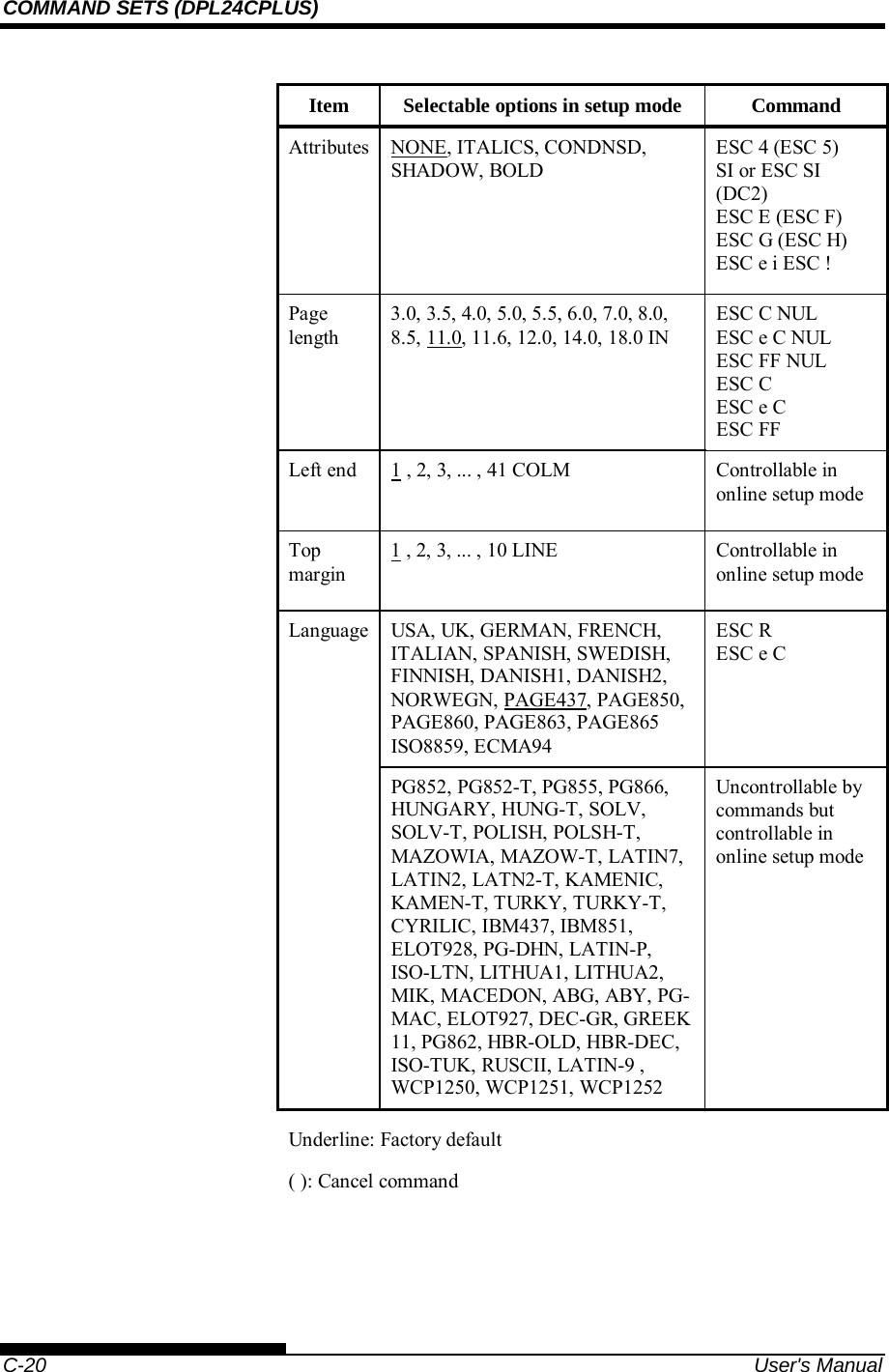
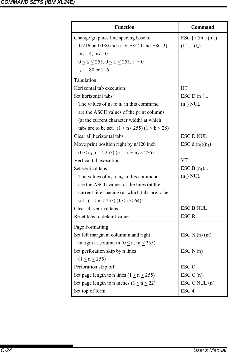
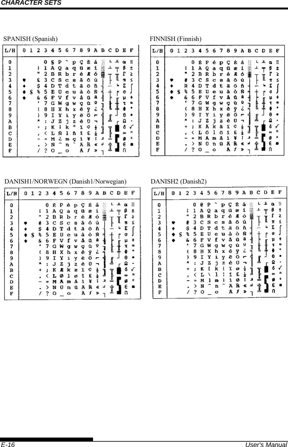
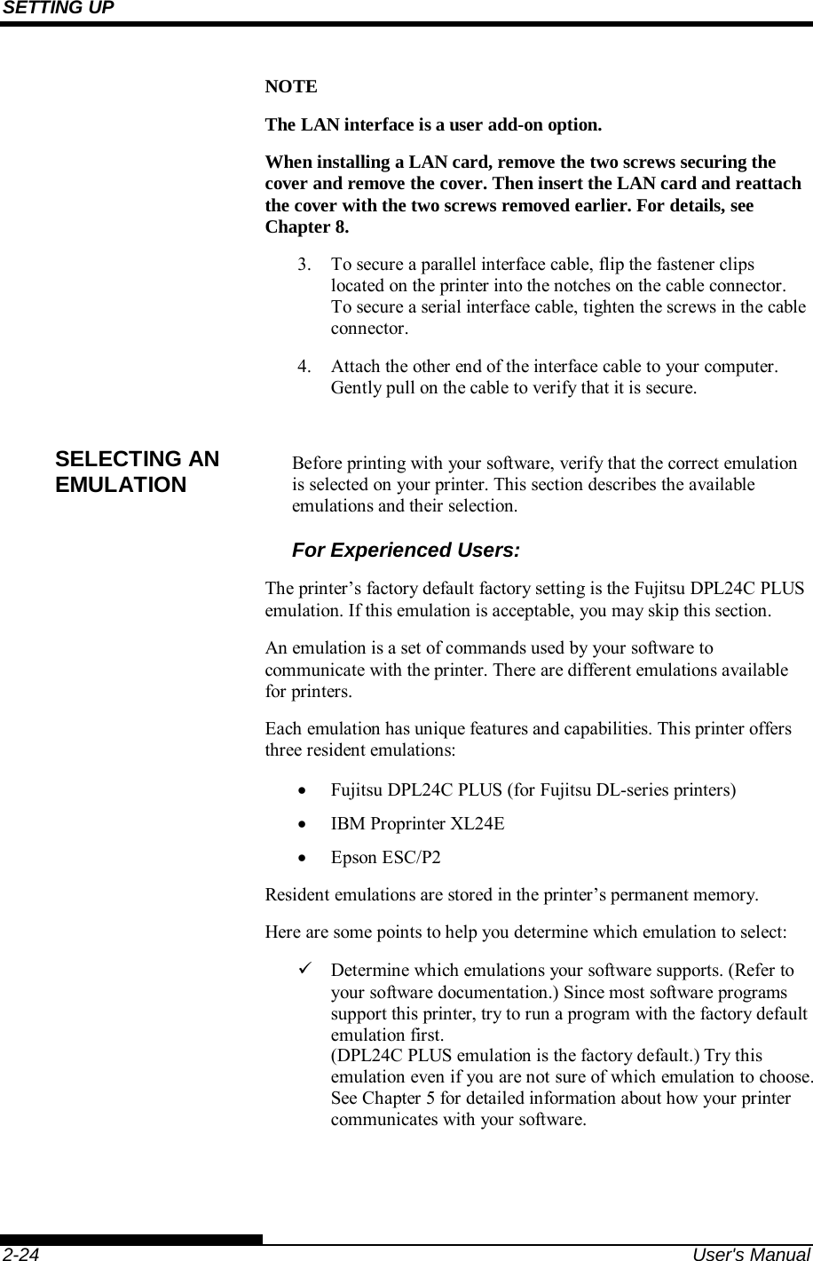
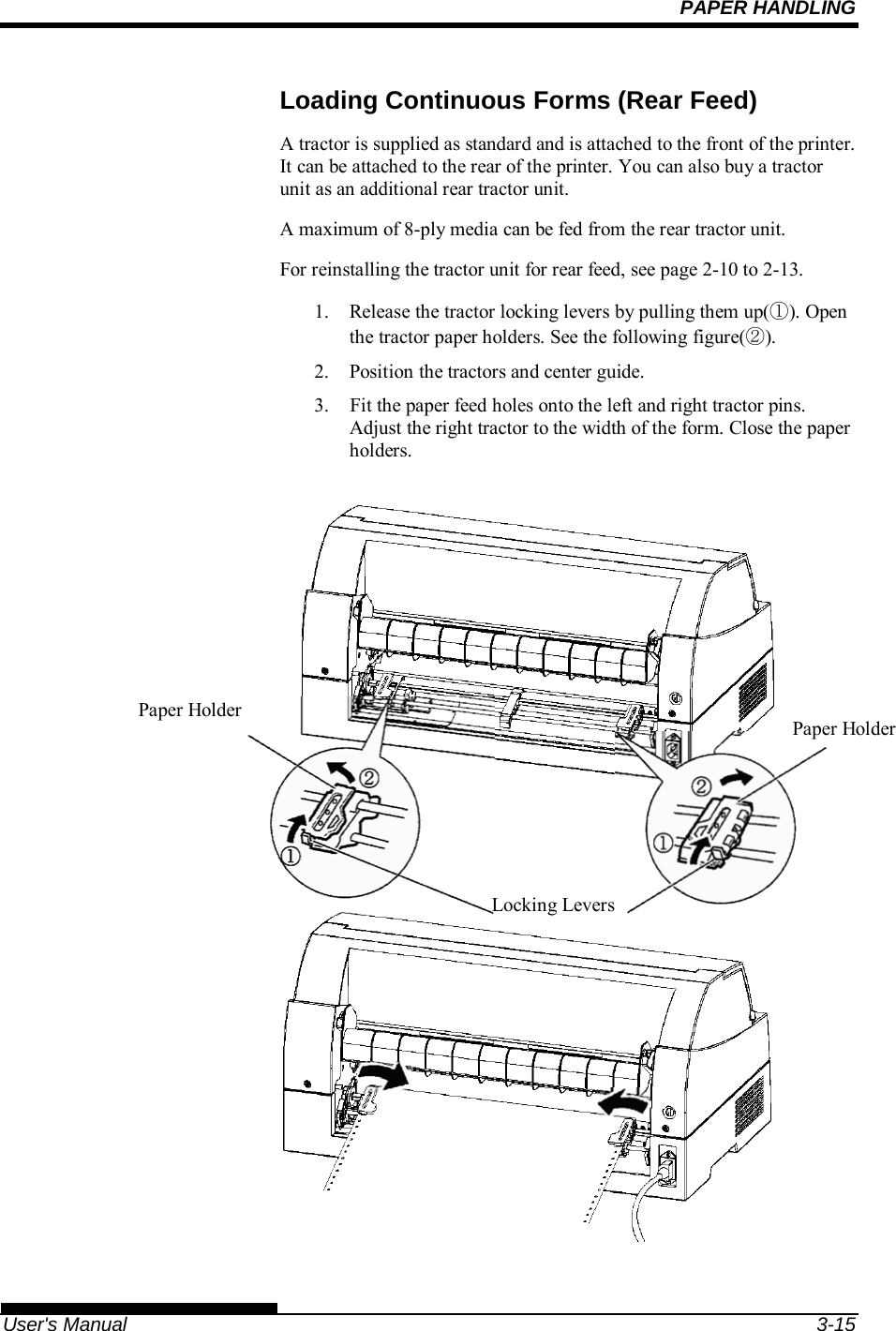
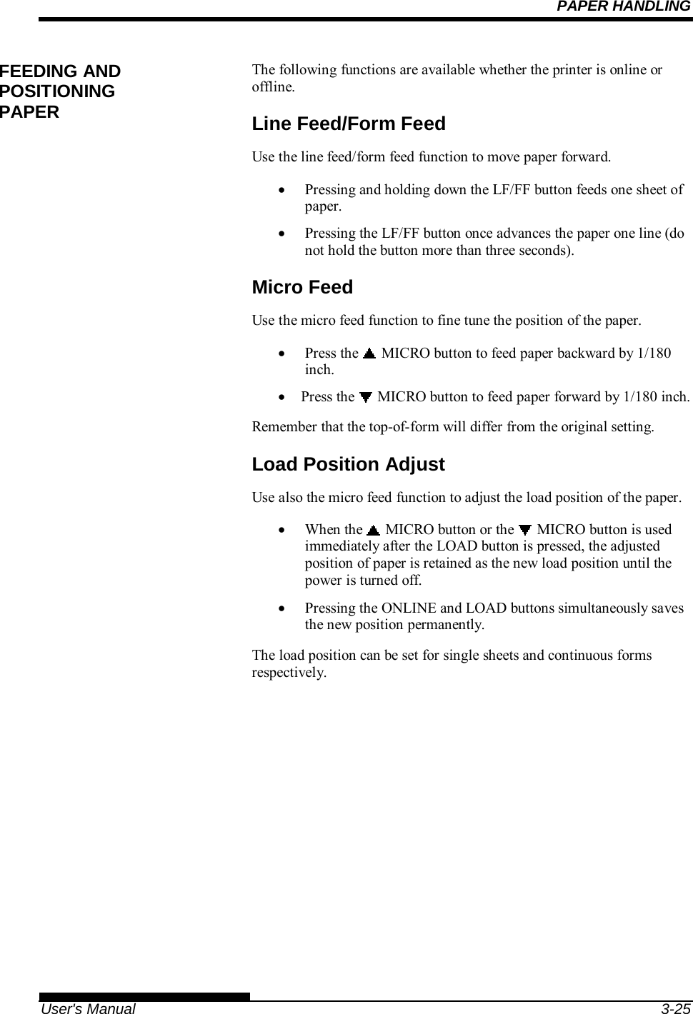
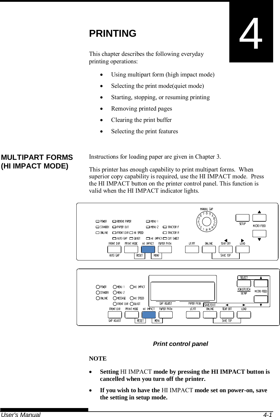
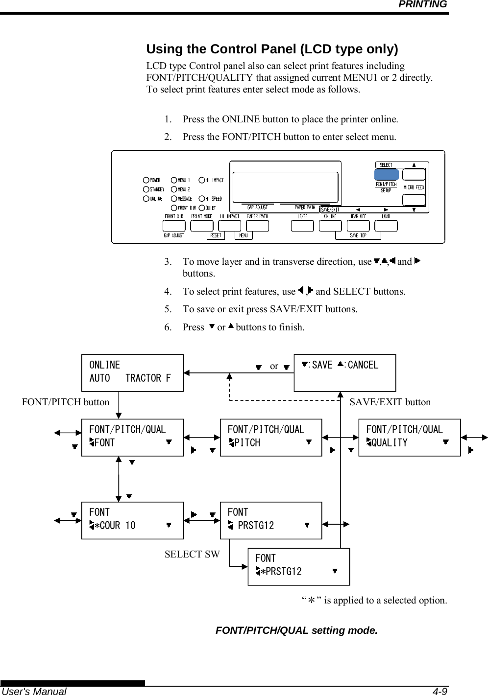
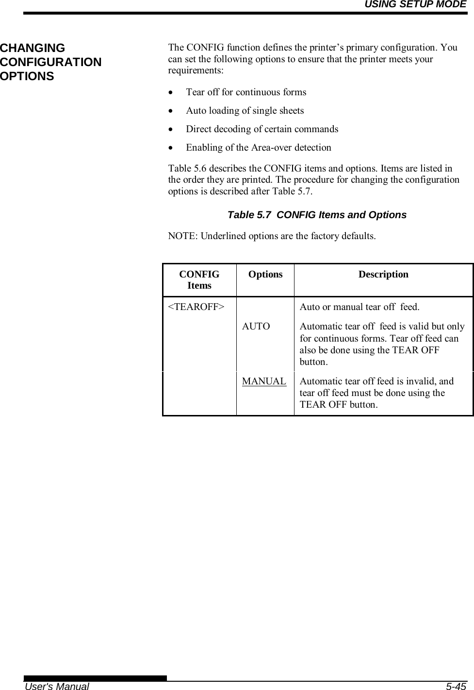
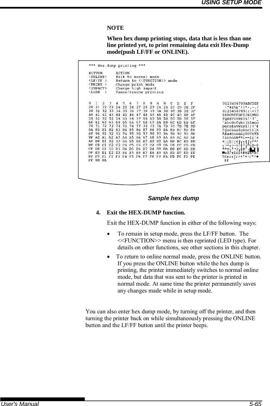
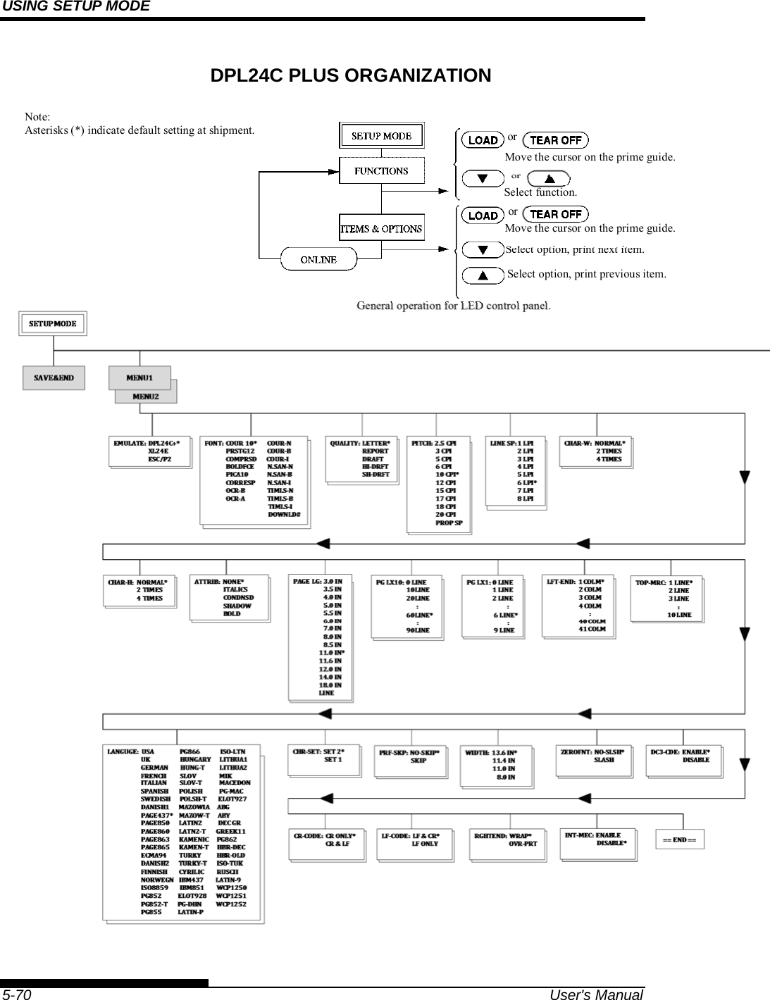
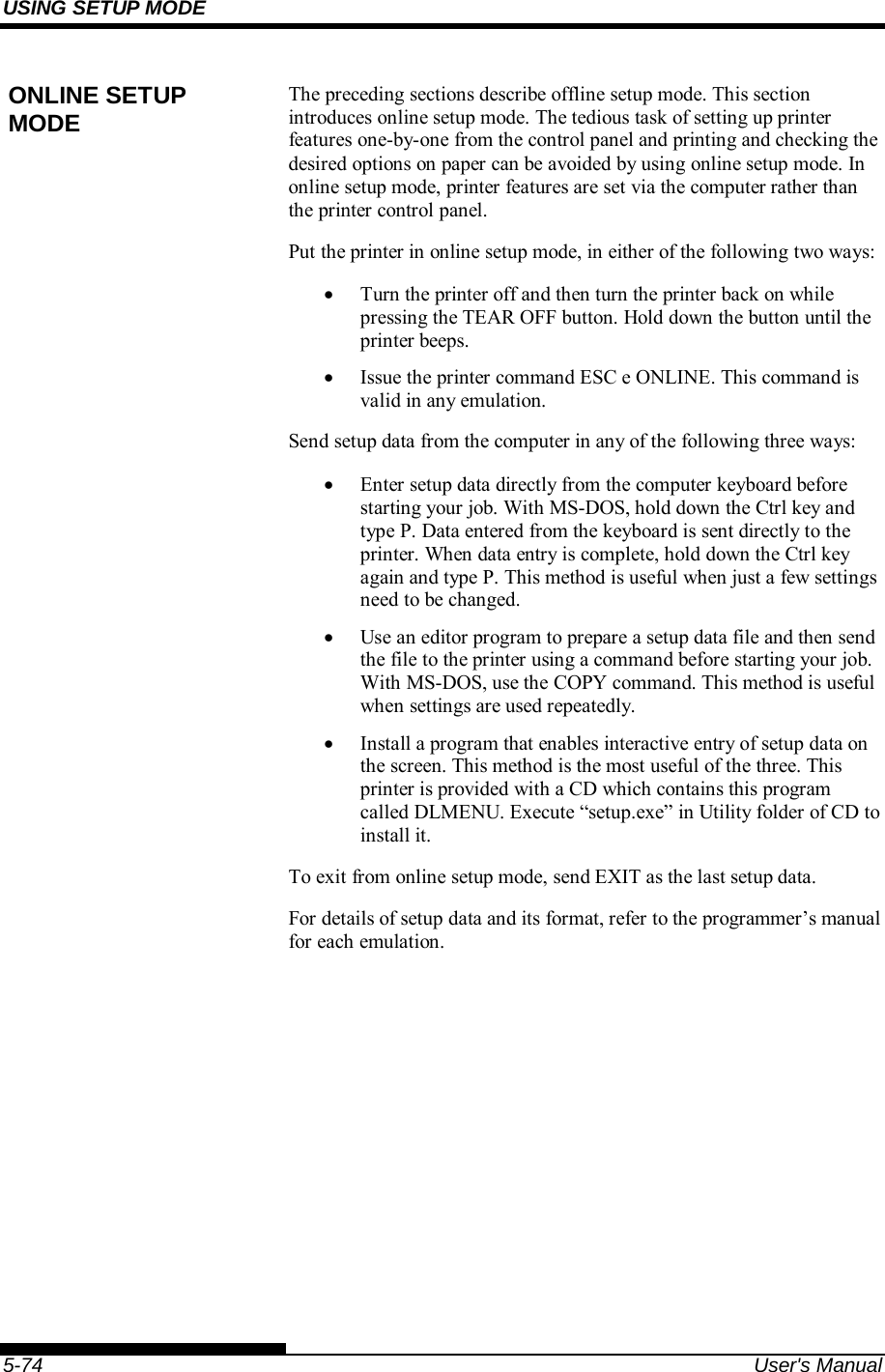
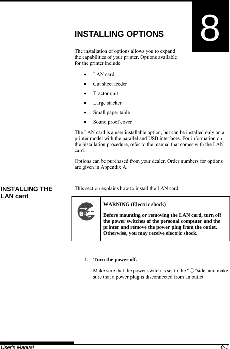
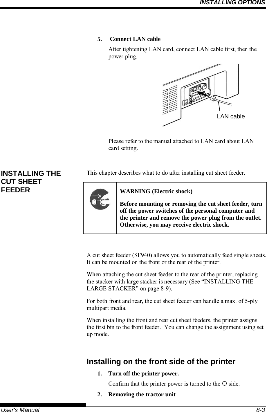
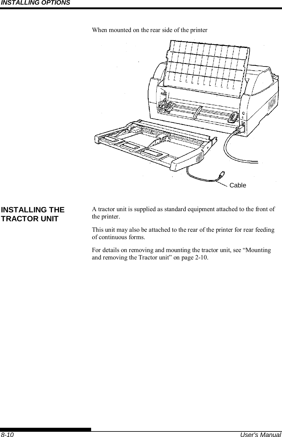
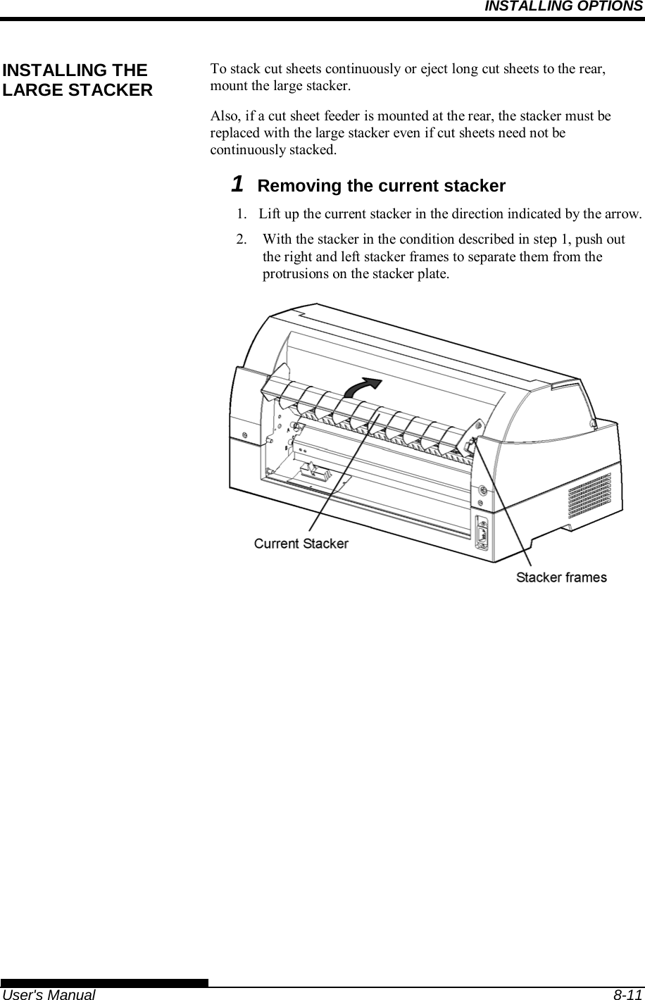
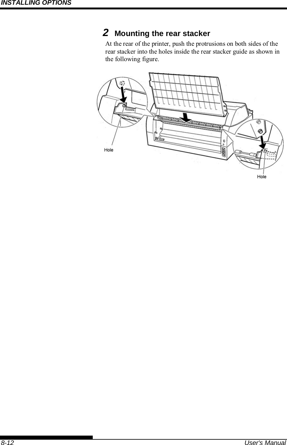
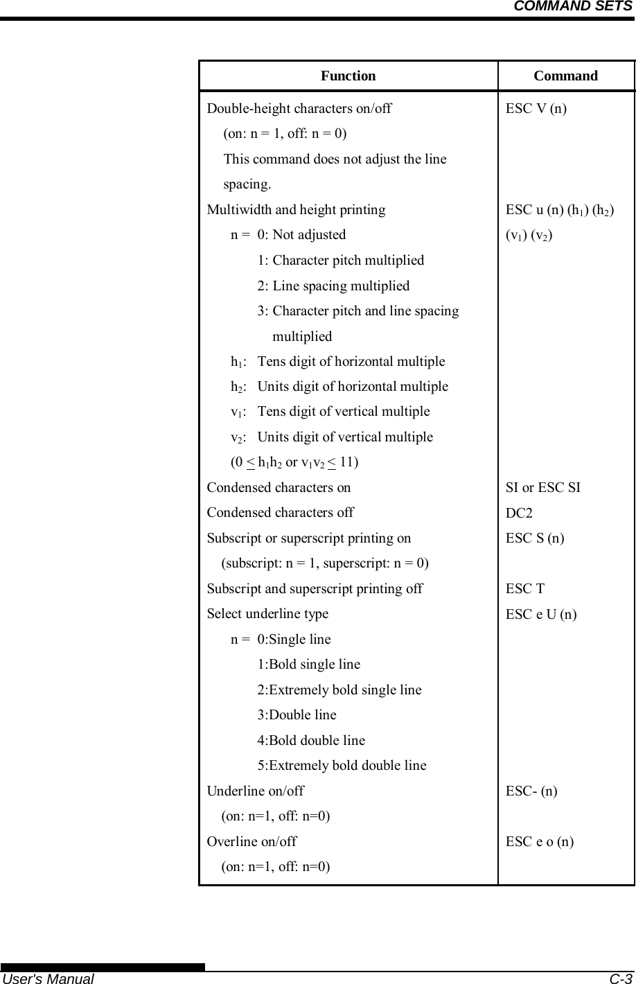
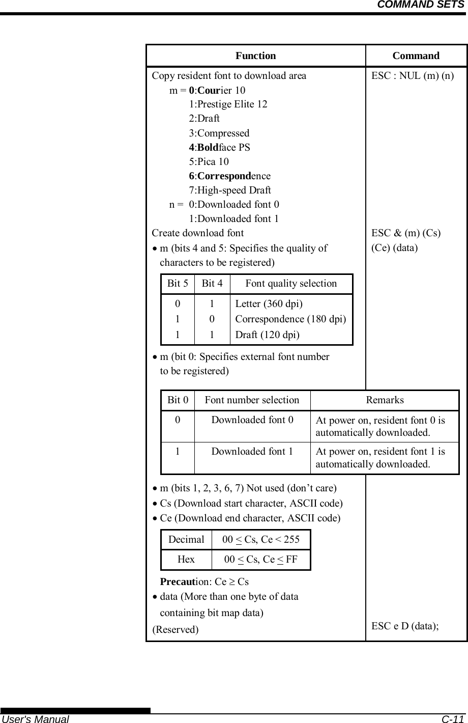
![SETTING UP 2-12 User's Manual Mounting and removing the tractor unit Tractor unit at the front [Removing the tractor unit] Raise the paper table. While pressing the lock levers of the tractor frames located on both sides of the tractor unit, lift out the tractor unit to remove it. [Mounting the tractor unit] 1) Position the U-shaped slots on both sides of the tractor unit over the guide pins of the printer unit. (To set the tractor unit in position, line it up with the groove of the left guide pin. The right guide pin has no groove). 2) Push down the shaft at the front of the tractor unit until it locks with an audible click. (Do not press the lock levers when pushing down the shaft.) Lock lever Lock lever Paper table Guide pin U-shaped slotU-shaped slotGuide pin](https://usermanual.wiki/Fujitsu-Isotec/020M33335A/User-Guide-2859436-Page-38.png)
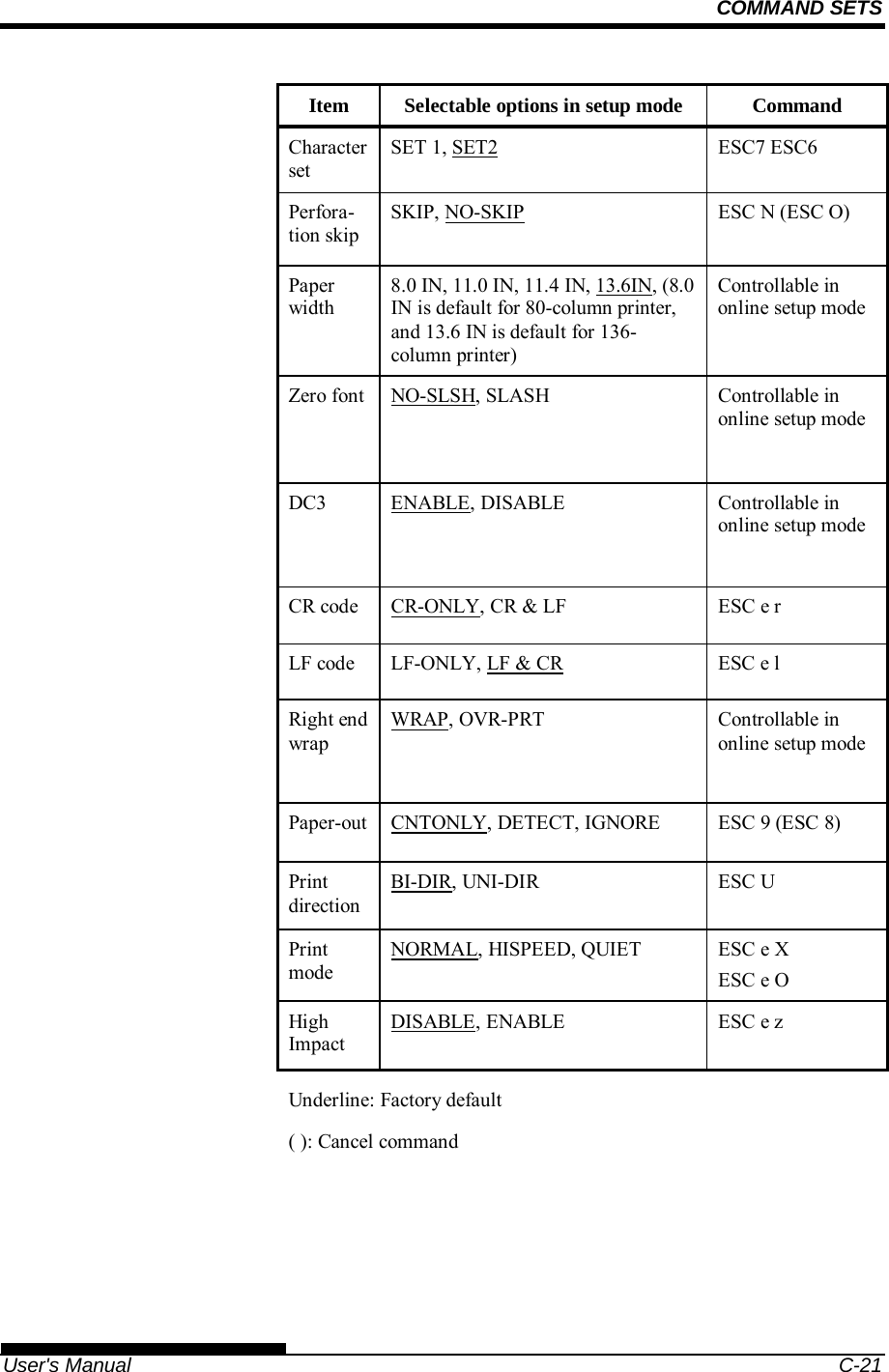
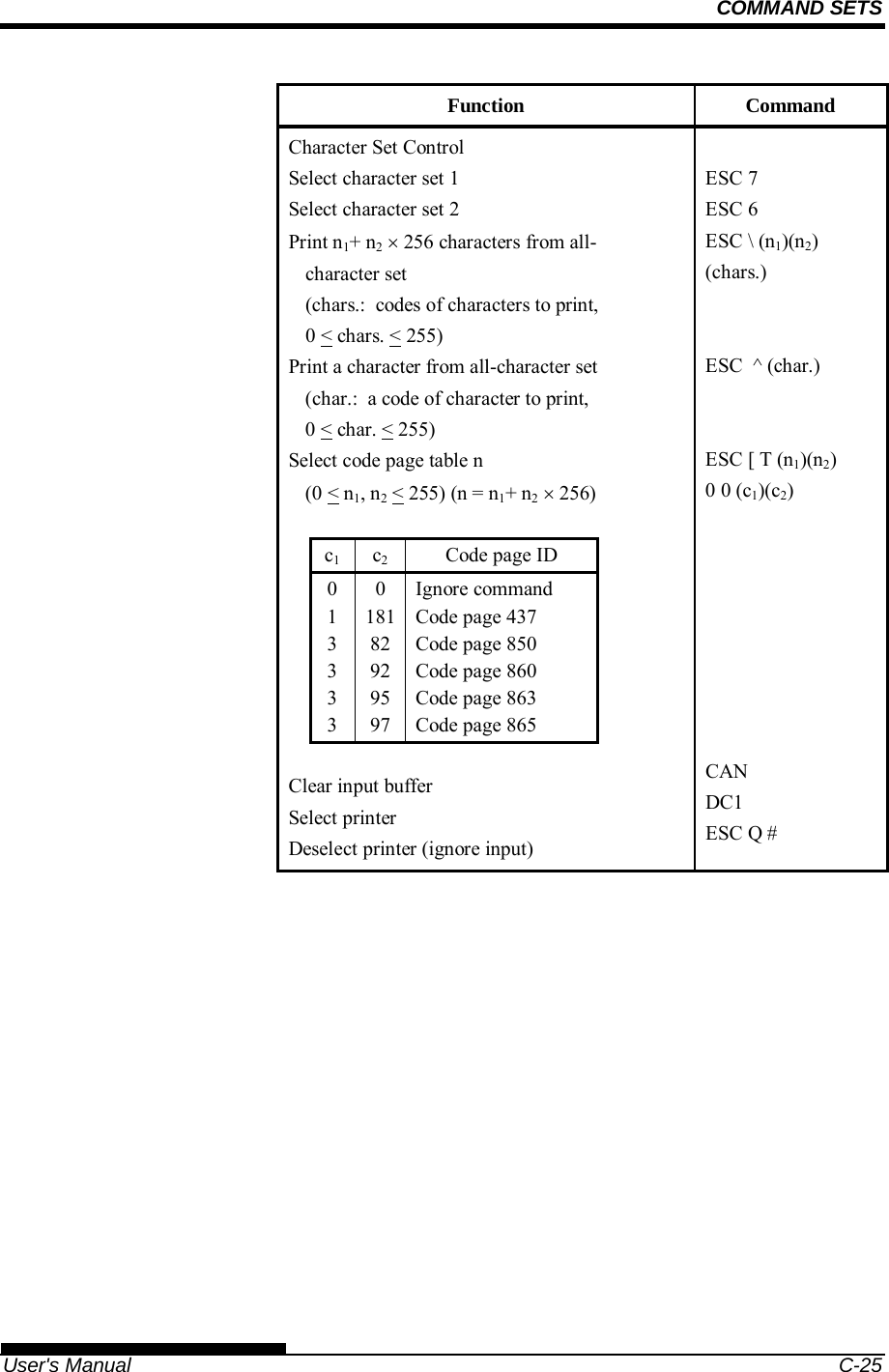
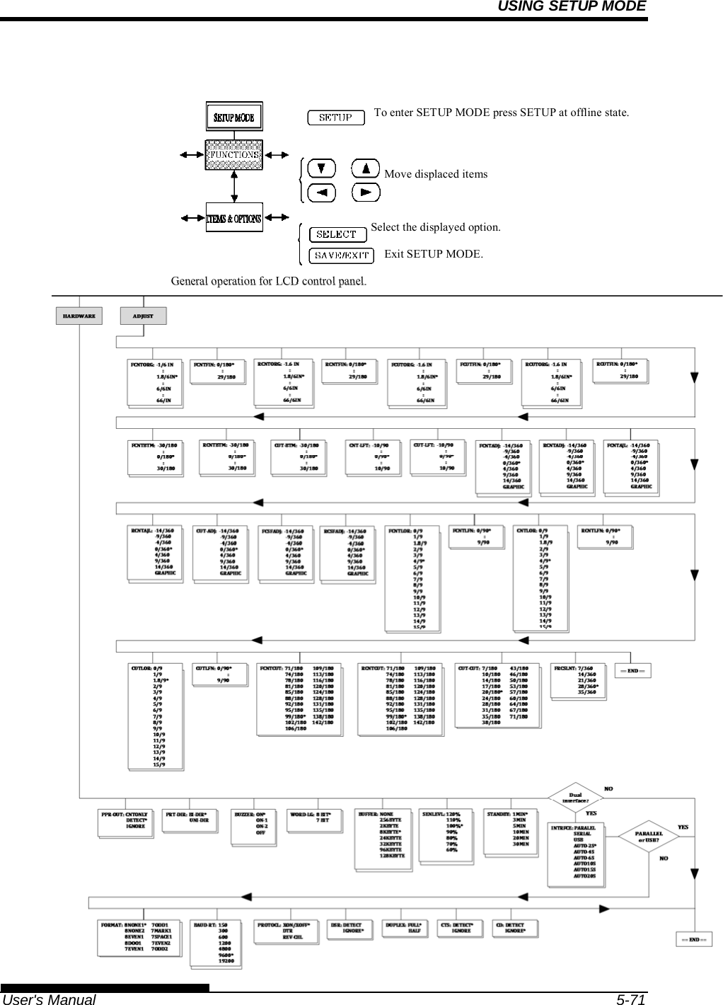
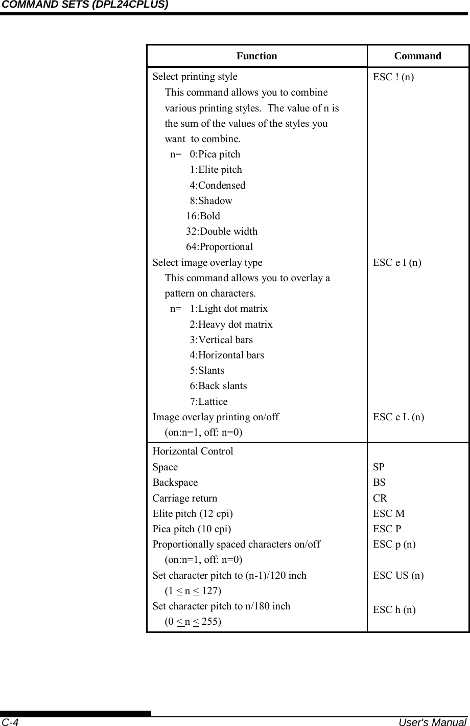
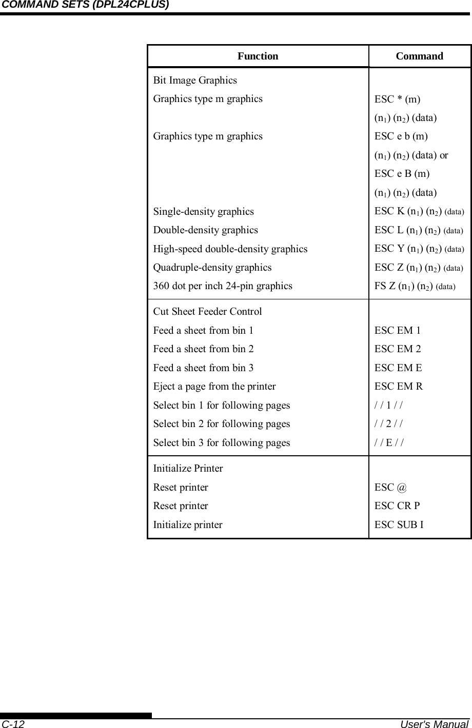
![SETTING UP User's Manual 2-13 3) Verify that the hooks on both sides of the tractor unit are securely hooked onto guide pin 2 as shown in the following figure. Tractor unit at the rear [Removing the tractor unit] While pressing the lock levers of the tractor frames located on both sides of the tractor unit, lift out the tractor unit to remove it.](https://usermanual.wiki/Fujitsu-Isotec/020M33335A/User-Guide-2859436-Page-39.png)
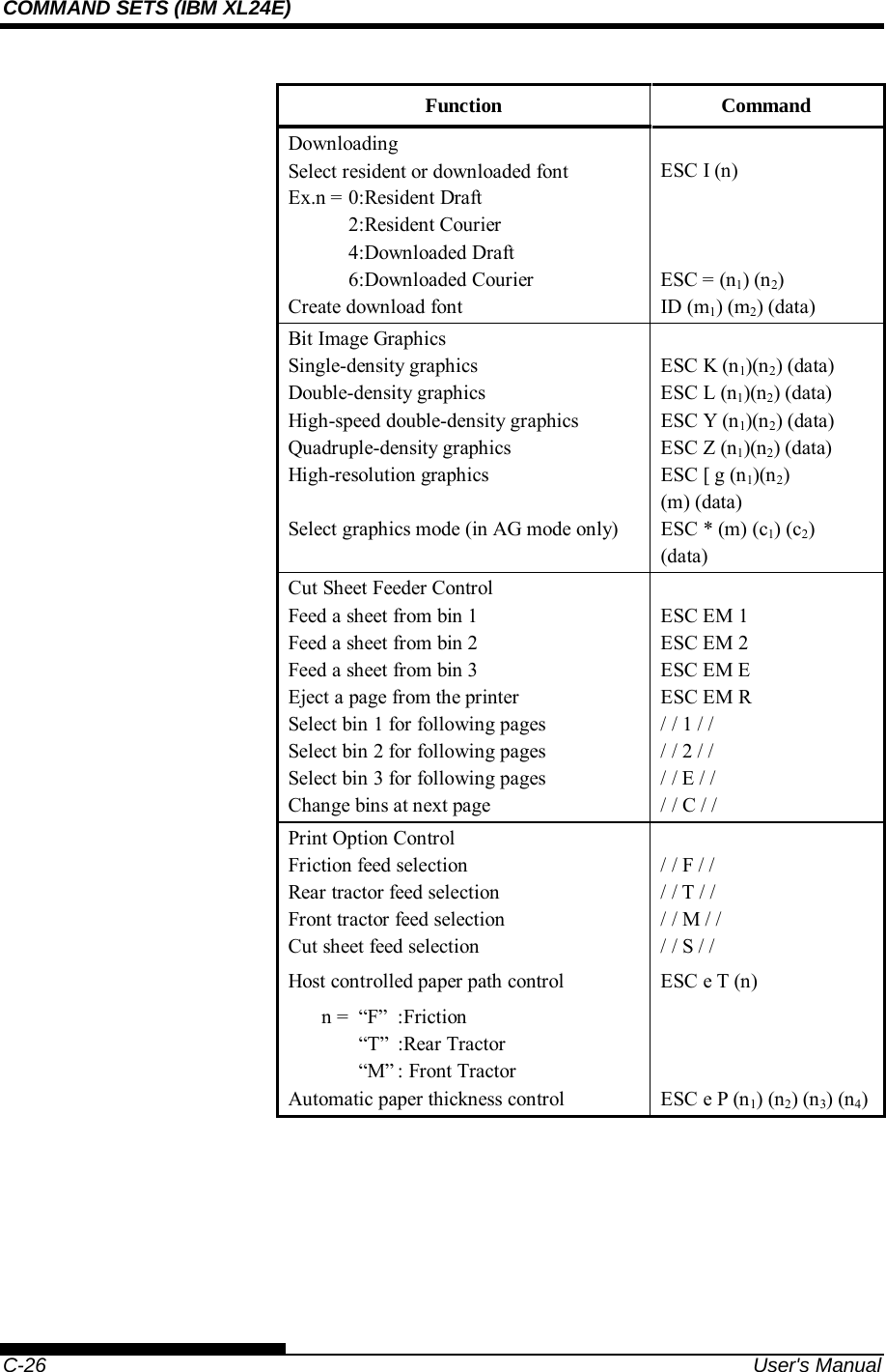
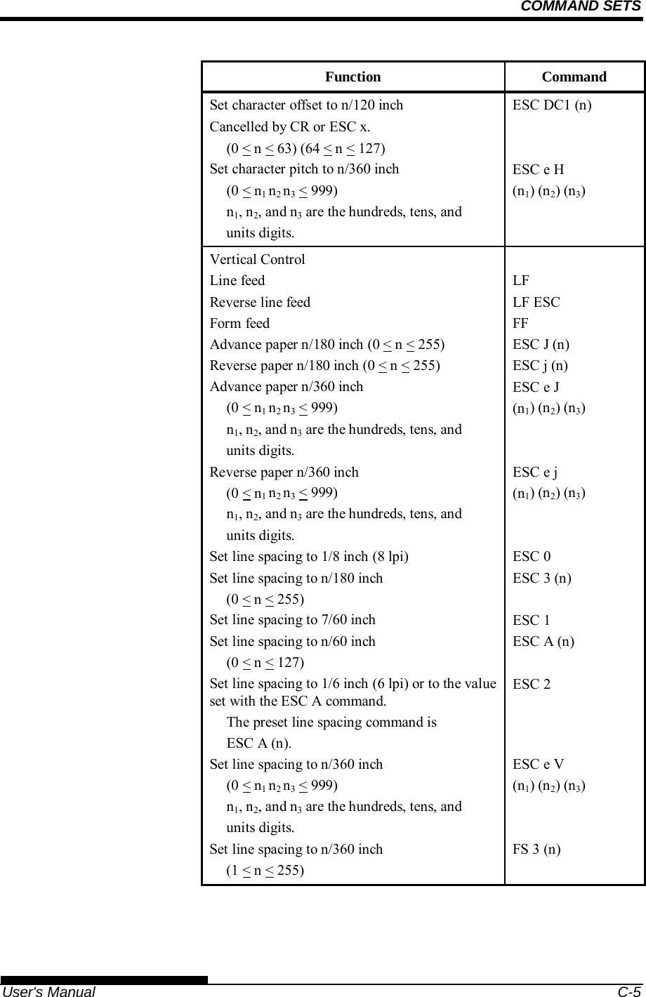
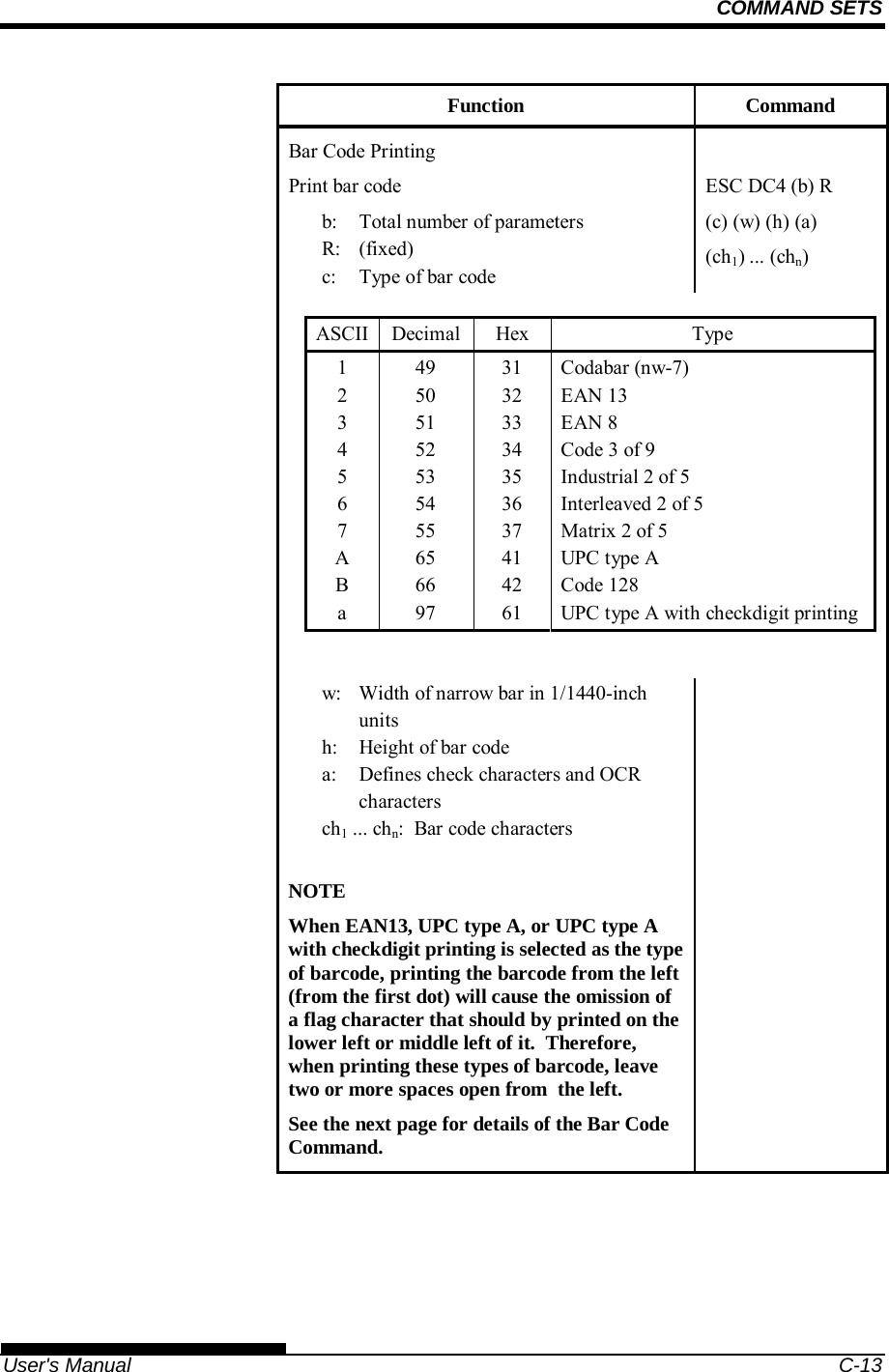
![SETTING UP 2-14 User's Manual [Mounting the tractor unit] 1) Position the U-shaped slots on both sides of the tractor unit over the guide pins of the printer unit. (To set the tractor unit in position, line it up with the groove of the left guide pin. The right guide pin has no groove). 2) Push down the shaft at the front of the tractor unit until it locks with an audible click. (Do not press the lock levers when pushing down the shaft.) 3) Verify that the hooks on both sides of the tractor unit are securely hooked onto guide pin 2 as shown in the following figure.](https://usermanual.wiki/Fujitsu-Isotec/020M33335A/User-Guide-2859436-Page-40.png)
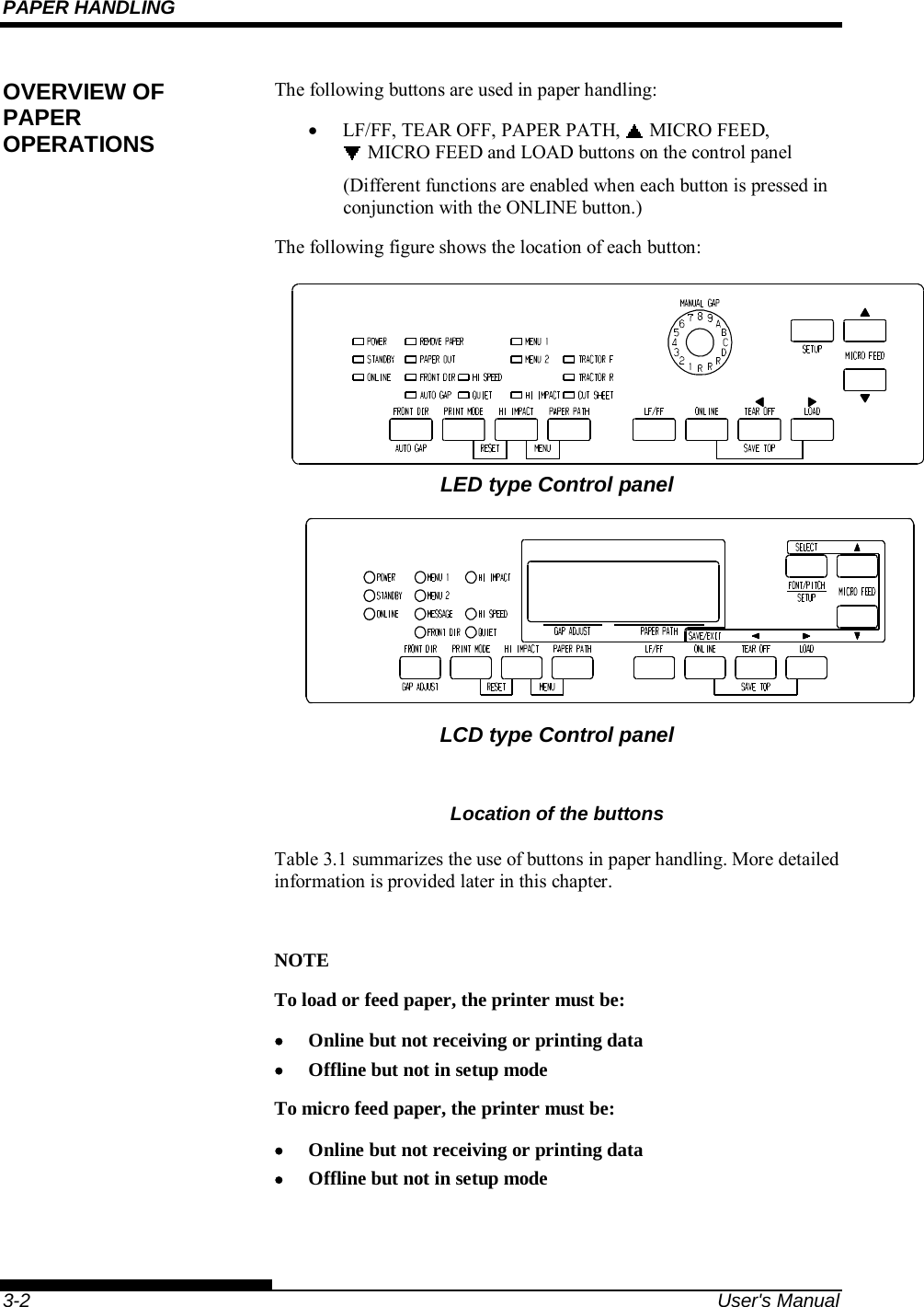
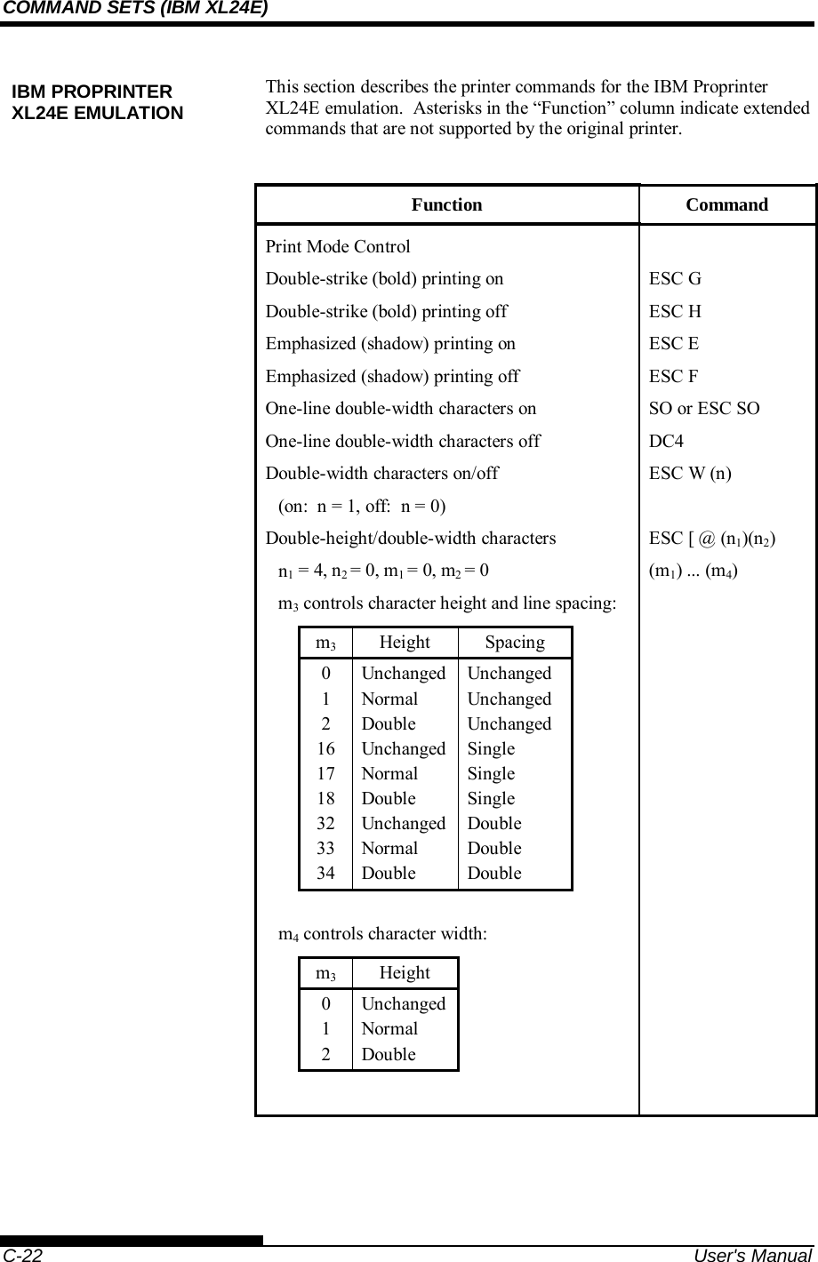
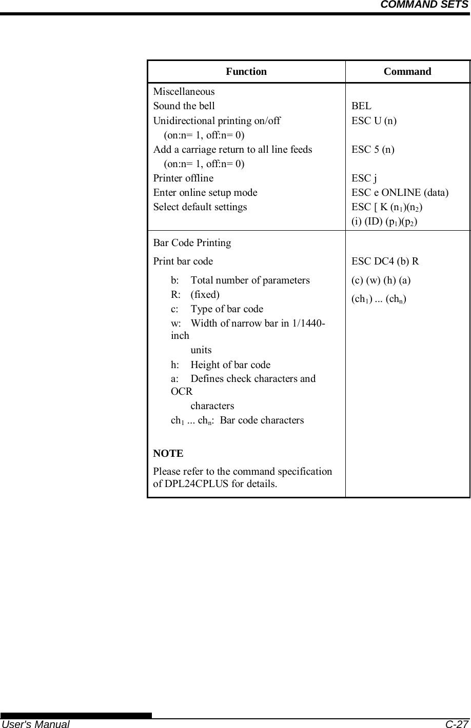
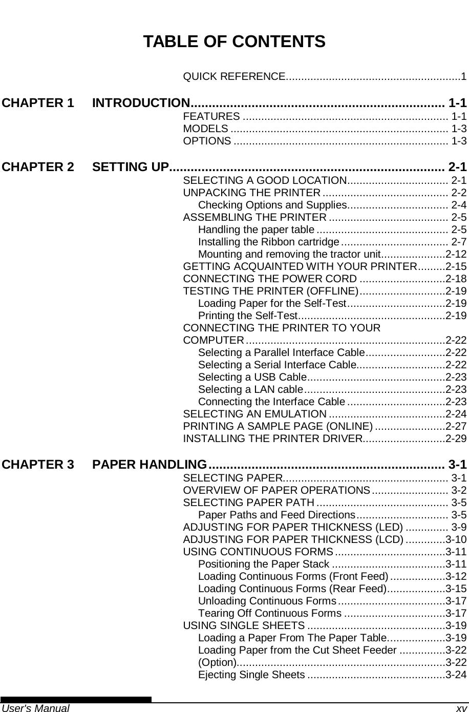
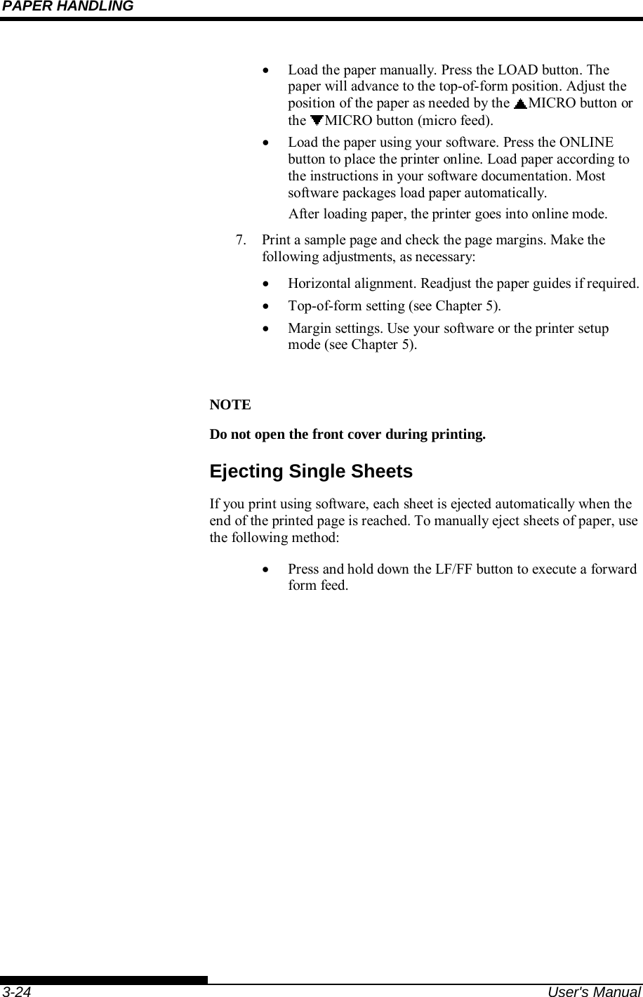
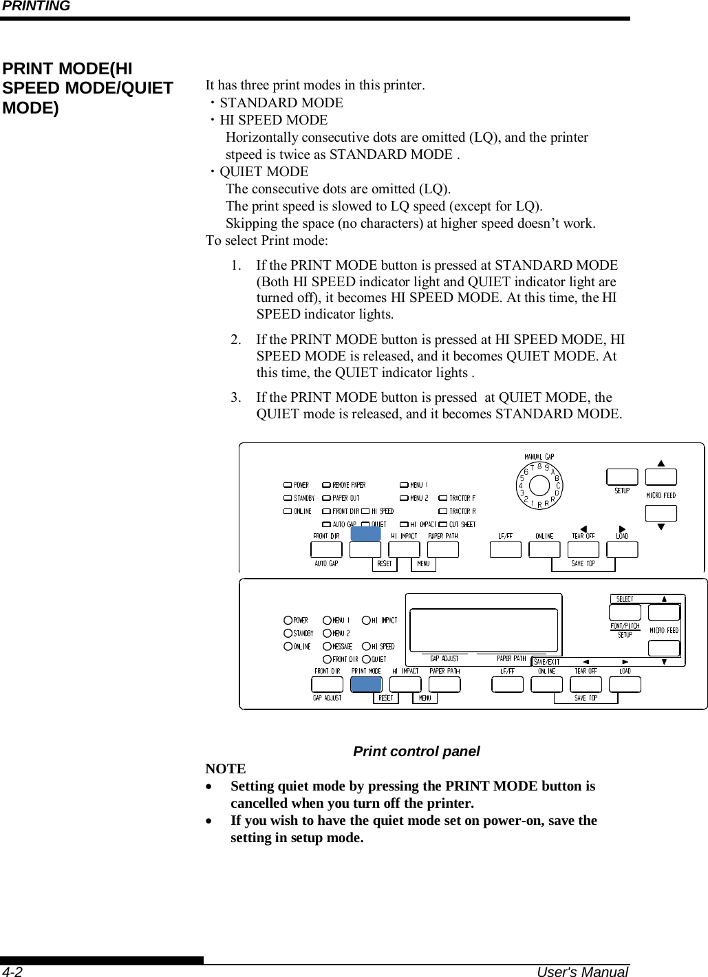
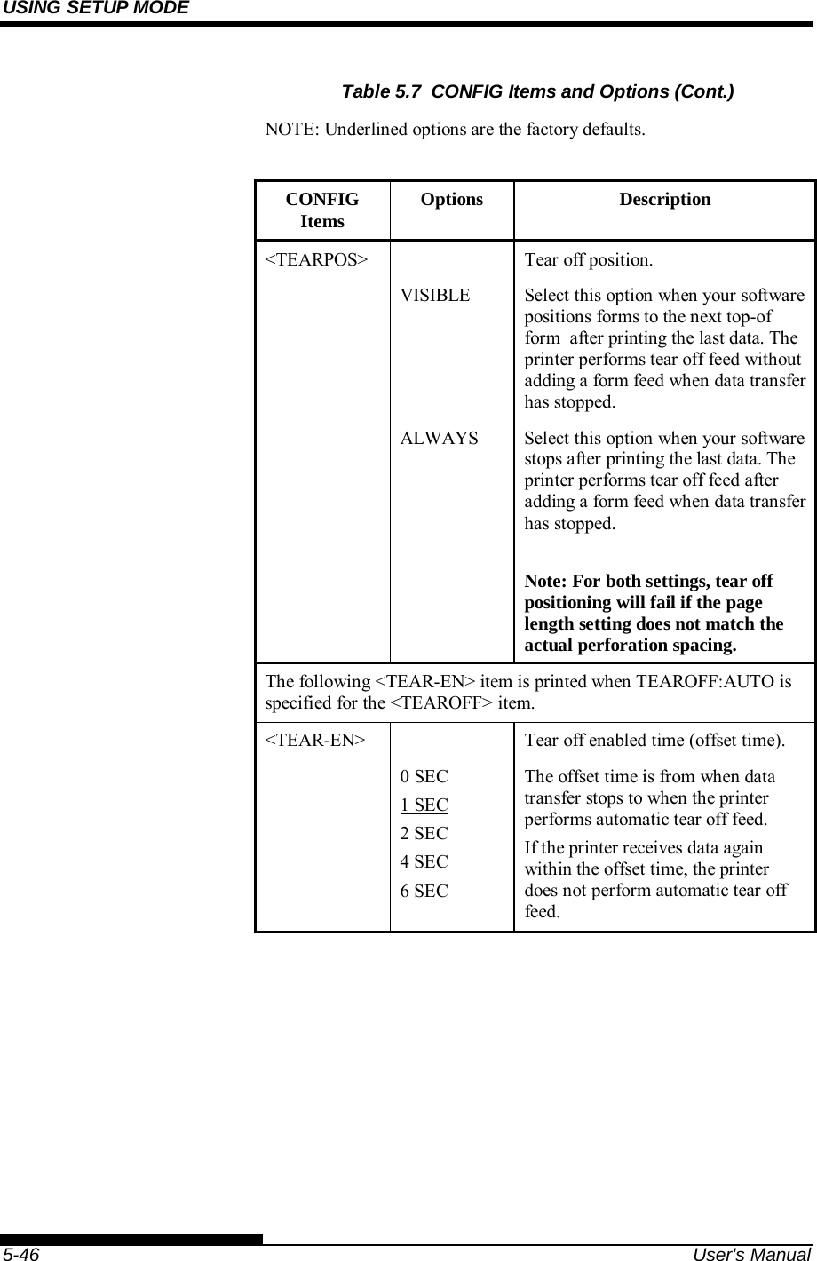
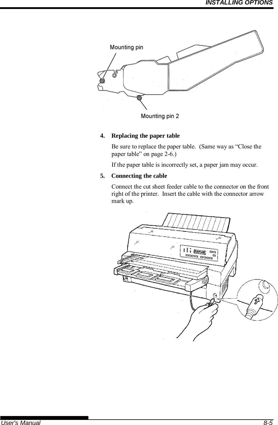
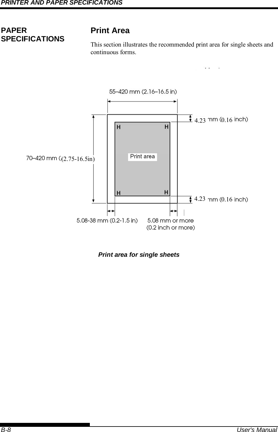
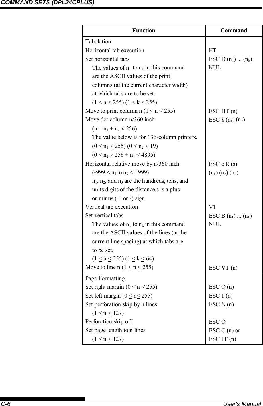
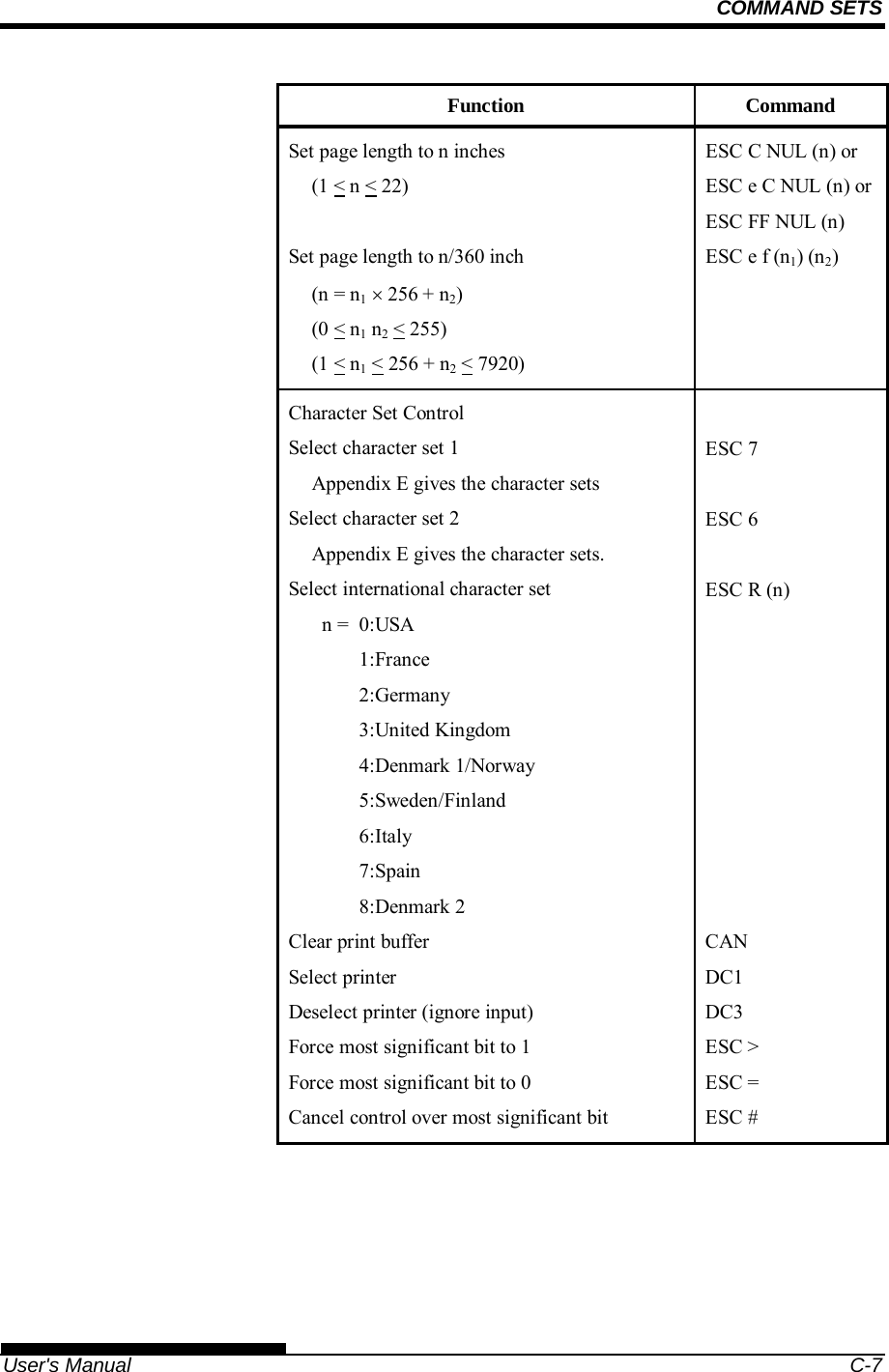
![PAPER HANDLING User's Manual 3-5 This printer has a variety of paper paths and feed directions. Paper Paths and Feed Directions See the following five cases. : Cut sheet : Continuous forms (n) : Input [n] : Output With front tractor (1) Front tractor Print Rear eject With rear tractor (2) Rear tractor Print Front eject SELECTING PAPER PATH (1) [1](2) [2]](https://usermanual.wiki/Fujitsu-Isotec/020M33335A/User-Guide-2859436-Page-61.png)
![PAPER HANDLING 3-6 User's Manual With front and rear tractors (either optional) (1) Front tractor Print Rear eject (2) Rear tractor Print Front eject (3) Paper table Print Paper table (4) Paper table Print Rear stacker (1) (2) [2] [1][3] (3)(4) [4]](https://usermanual.wiki/Fujitsu-Isotec/020M33335A/User-Guide-2859436-Page-62.png)
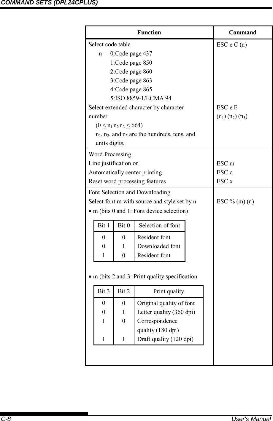
![PAPER HANDLING User's Manual 3-7 In the next two cases, the number of cut sheets stacked in the printer may be reduced depending on printing conditions and environments. Follow the notes. With rear tractor and front optional cut sheet feeder and large stacker(optional) . (2) Rear tractor Print Front eject (3) Paper table Print Paper table (4) Paper table Print Rear stacker (5) Front cut sheet feeder Print Paper table (6) Front cut sheet feeder Print Rear stacker With front or rear tractor (either optional)and rear optional cut sheet feeder and large stacker(optional). In addition, the front and rear tractor (either is optional) can be mounted. (1) Front tractor Print Rear eject (2) Rear tractor Print Front eject (3) Paper table Print Paper table (4) Paper table Print Rear stacker (7) Rear cut sheet feeder Print Paper table (8) Rear cut sheet feeder Print Rear stacker (5)(6) (2) [2] [3] [5](3)(4) [4] [6](1)(2) [2] [1][3][7] (3)(4) [4](7)(8) [8]](https://usermanual.wiki/Fujitsu-Isotec/020M33335A/User-Guide-2859436-Page-63.png)
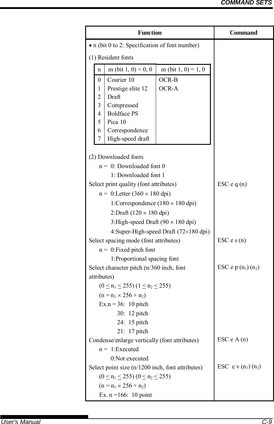
![PAPER HANDLING 3-8 User's Manual With rear tractor and front and rear optional cut sheet feeder and large stacker. In addition, the front and rear tractor (either is optional) can be mounted. (2) Rear tractor Print Front eject (3) Paper table Print Paper table (4) Paper table Print Rear stacker (5) Front cut sheet feeder Print Paper table (6) Front cut sheet feeder Print Rear stacker (7) Rear cut sheet feeder Print Paper table (8) Rear cut sheet feeder Print Rear stacker NOTES When remaining the ejected cut sheet on the paper table, the REMOVE PAPER indicator blinks and the printer stops printing. Before restarting printing, be sure to remove the cut sheet. You must remove cut sheets one by one immediately after ejection. This is required because the printer may load an ejected sheet again or an ejected sheet may push the previous sheets out of the printer. To eject sheets larger than A4 size onto the paper table, the paper table must be replaced with the optional large cut sheet table to prevent ejected sheets from falling off the paper table. When printing thin paper, multipart copy paper, or large size paper, frequently remove the paper from the rear stacker or the paper table. (2) [2] [3][5][7] (3)(4) [4] (7)(8) [8] (5)(6) [6]](https://usermanual.wiki/Fujitsu-Isotec/020M33335A/User-Guide-2859436-Page-64.png)
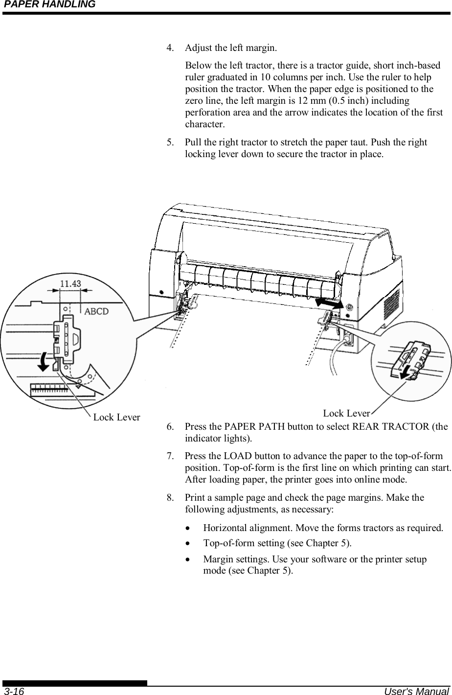
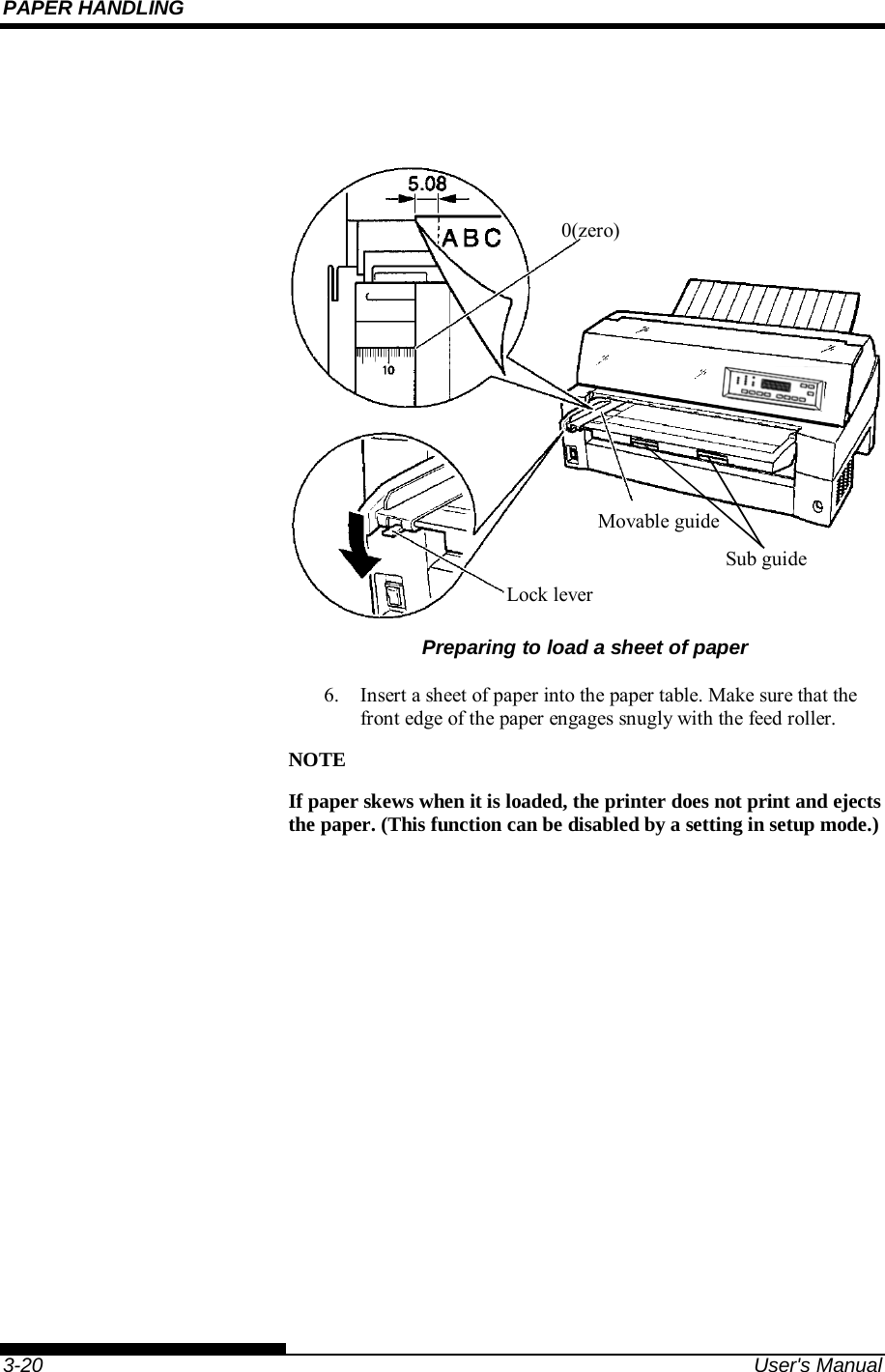
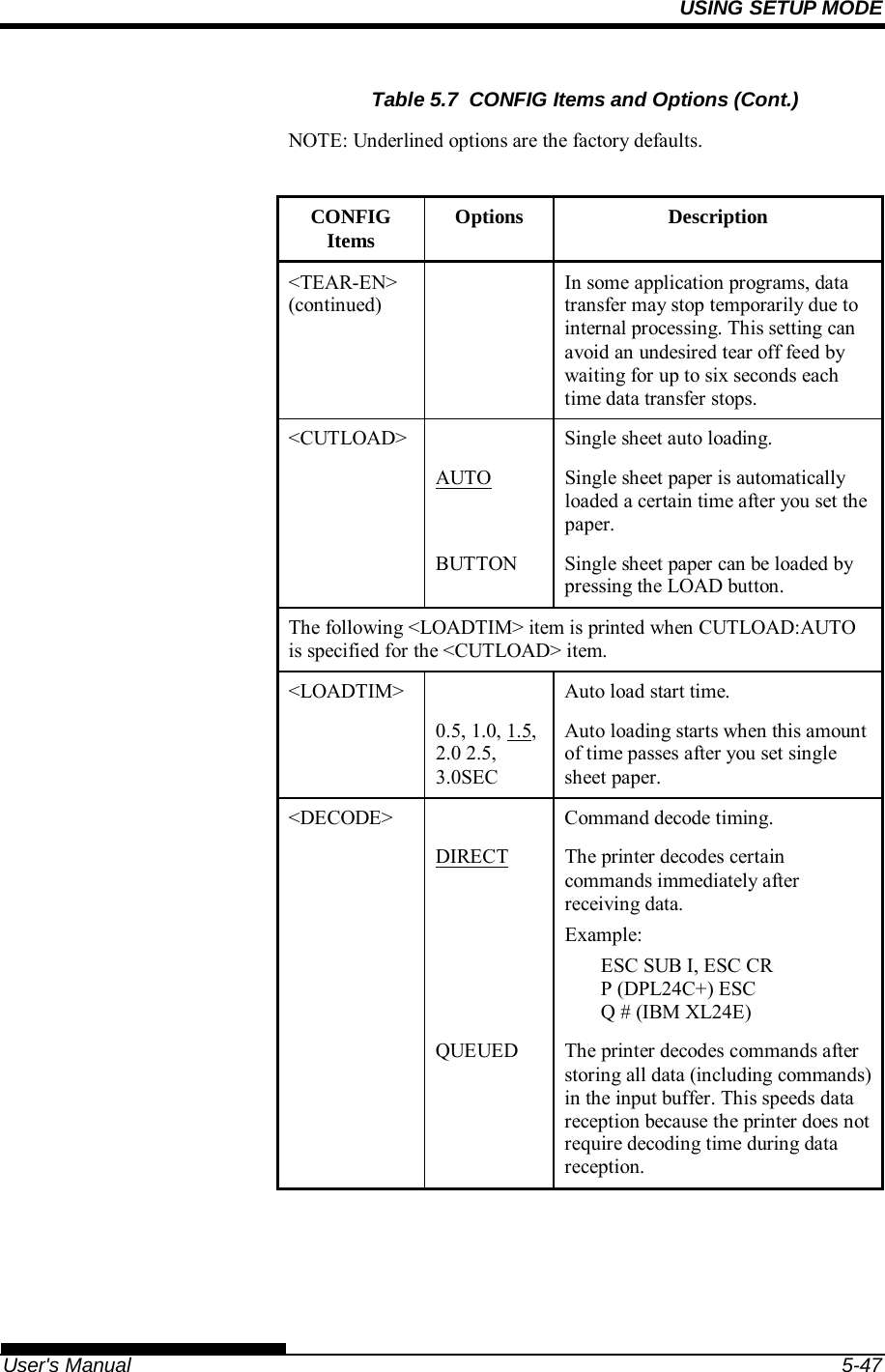
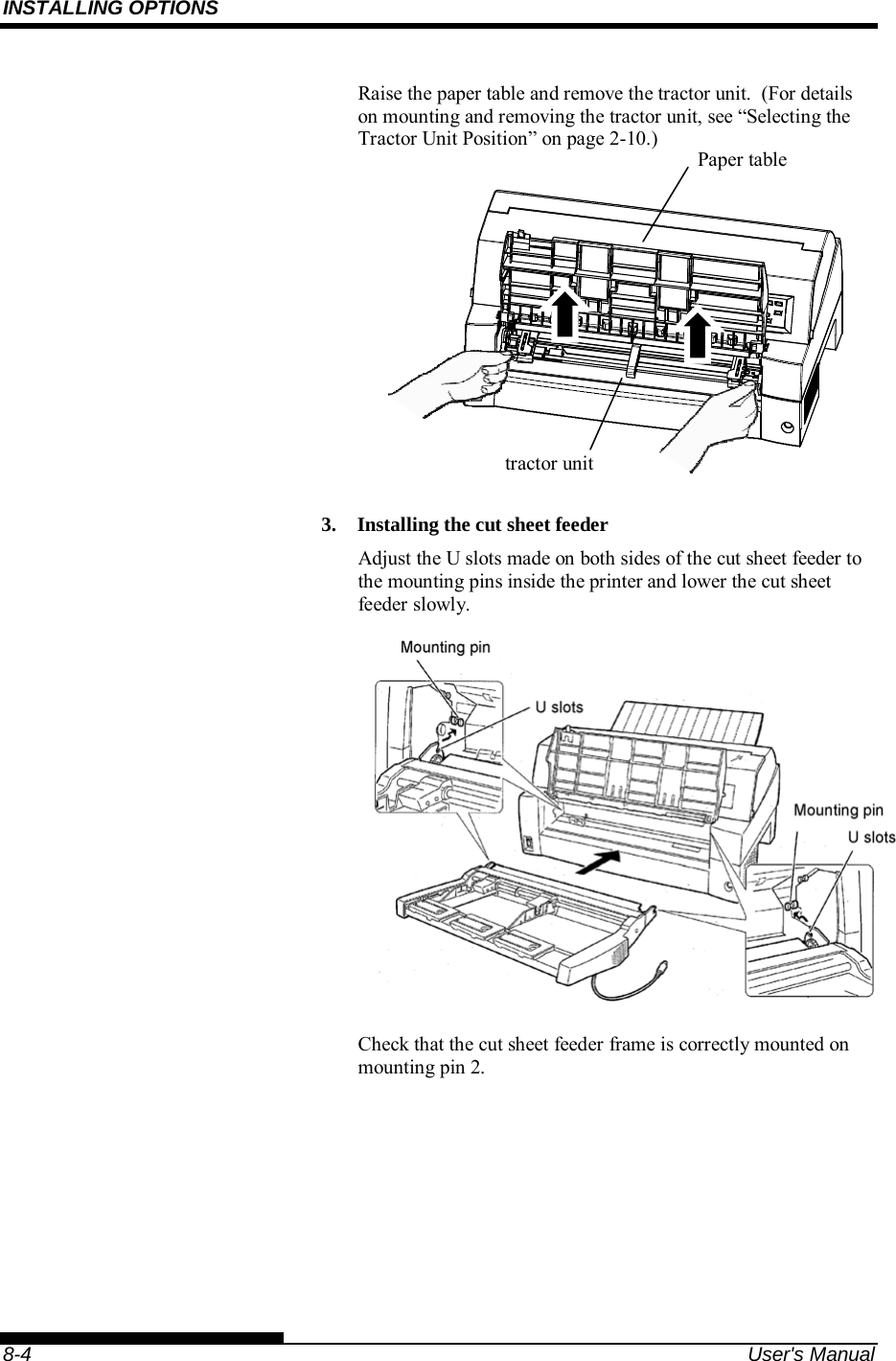
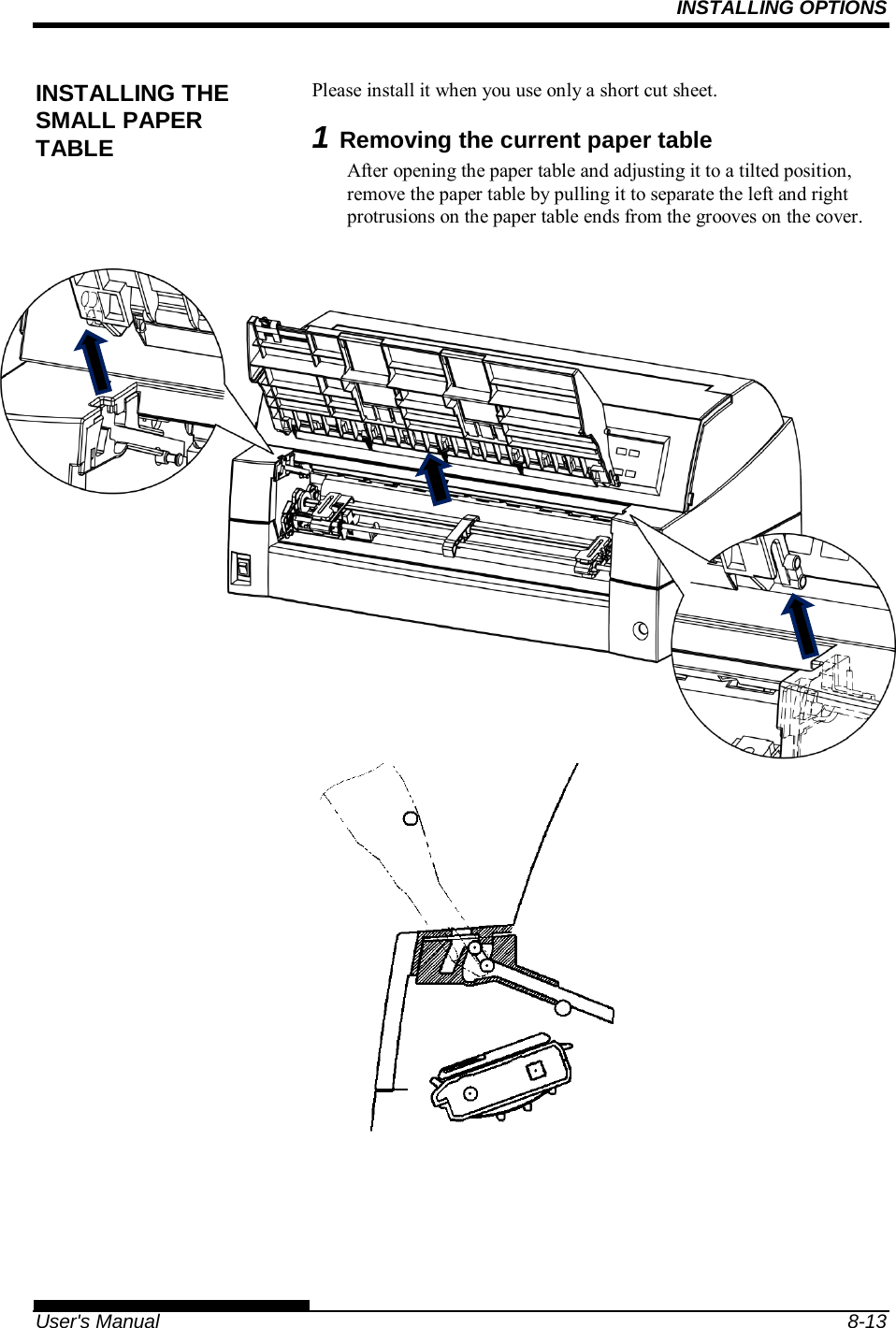
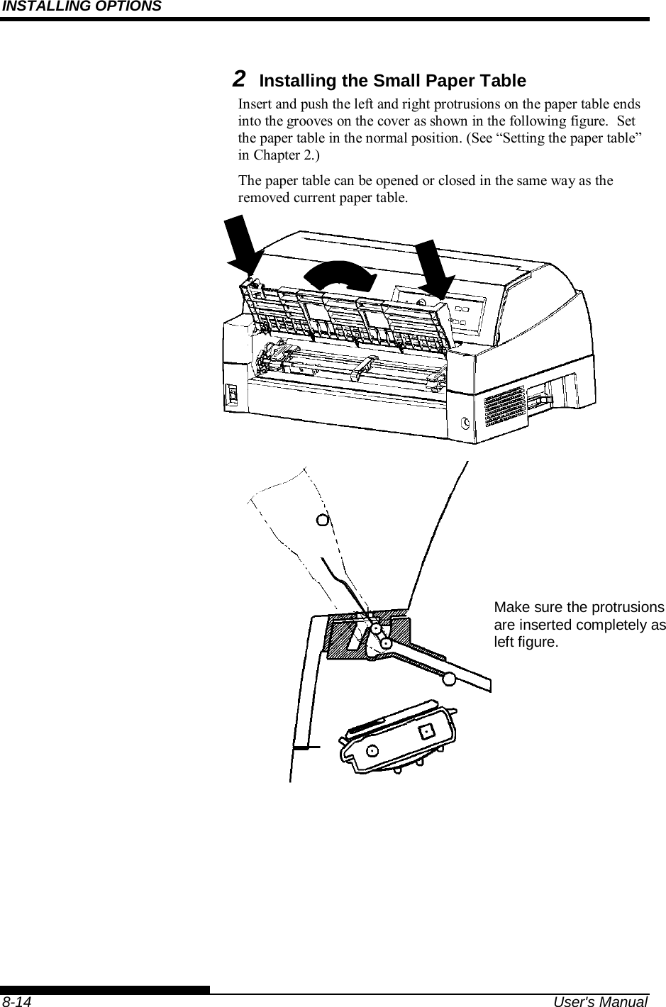
![PAPER HANDLING User's Manual 3-19 This section describes how to load paper from the paper table or cut sheet feeder. The paper table allows paper to be loaded manually, one sheet at a time. A cut sheet feeder allows paper to be loaded automatically from the paper bin. Loading a Paper From The Paper Table. To load a sheet of paper from the paper table: 1. Make sure that the printer is turned on. 2. Press the PAPER PATH button to select CUT SHEET (the indicator lights). 3. Press the FRONT DIR button to select the direction of ejecting single sheets. Front ejection — FRONTDIR indicator lights. Rear ejection — FRONTDIR indicator doesn’t light. 4. Adjust the left margin. On the left hand side of the paper table, a scale graduated in units of 1 [mm]. When the paper guide is positioned at scale 0 [mm], the left margin is 5 mm (0.2 inch). Push the lock lever down to secure the guide. 5. Pull the sub-guide out as required to the paper size. NOTE When using the paper whose width is under 100 mm (4 inch), position the paper guide at scale 0 [mm]. USING SINGLE SHEETS](https://usermanual.wiki/Fujitsu-Isotec/020M33335A/User-Guide-2859436-Page-75.png)
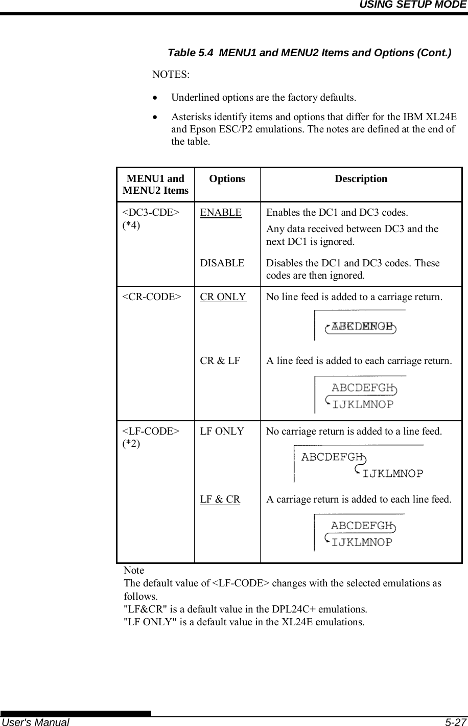
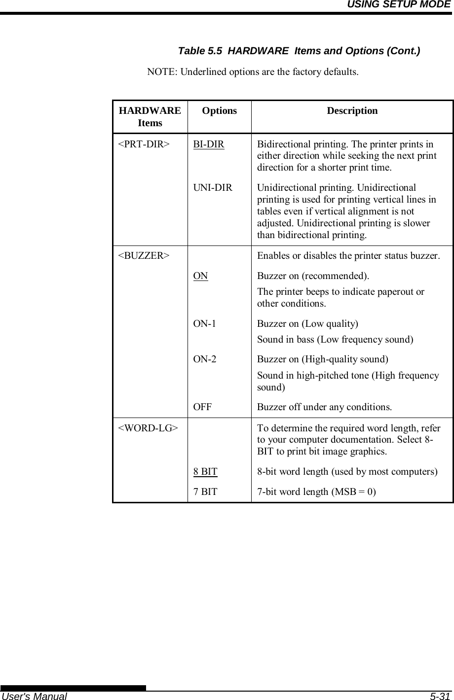
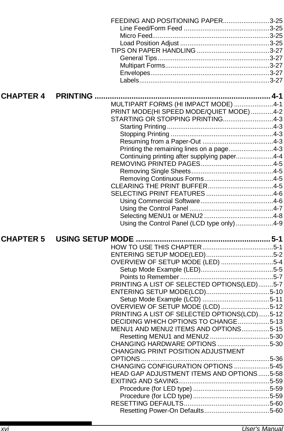
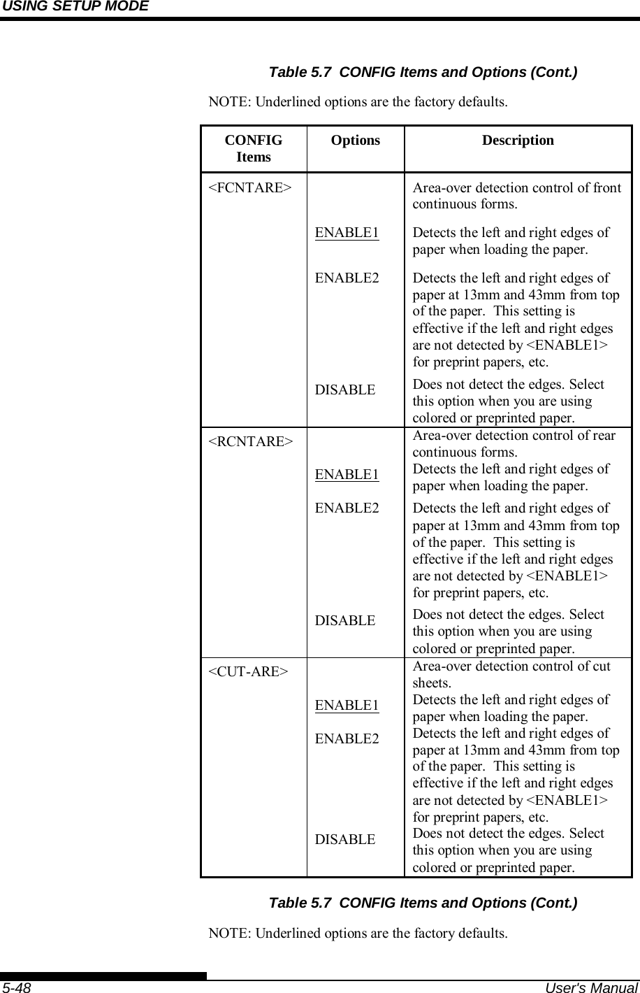
![USING SETUP MODE User's Manual 5-37 Table 5.6 ADJUST Items and Options NOTE: The top of form position is out of paper at [-1/6 IN] and [0/6 IN]. When printing, set the margin more than 1/6inch. ADJUST Items Options Description <FCNTORG> -1/6 IN 0/6 IN 1/6 IN 1.8/6 IN : 6/6 IN : 66/6 IN Sets the top-of-form for front continuous forms in increments of 1/6 inch (4.2 mm) from the physical top of the page. The default is recommended if your top margin is not software-specified. A setting of 1/6 inch is preferable when your top margin is software-specified. <FCNTFIN> 0/180, ..., 29/180 Fine-tunes the top-of-form position for front continuous forms. Increases top-of-form in increments of 1/180 inch (0.14 mm). <RCNTORG> -1/6 IN 0/6 IN 1/6 IN 1.8/6 IN : 6/6 IN : 66/6 IN Sets the top-of-form for rear continuous forms in increments of 1/6 inch (4.2 mm) from the physical top of the page. The default is recommended if your top margin is not software-specified. A setting of 1/6 inch is preferable when your top margin is software-specified. <RCNTFIN> 0/180, ..., 29/180 Fine-tunes the top-of-form position for rear continuous forms. Increases top-of-form in increments of 1/180 inch (0.14 mm).](https://usermanual.wiki/Fujitsu-Isotec/020M33335A/User-Guide-2859436-Page-131.png)
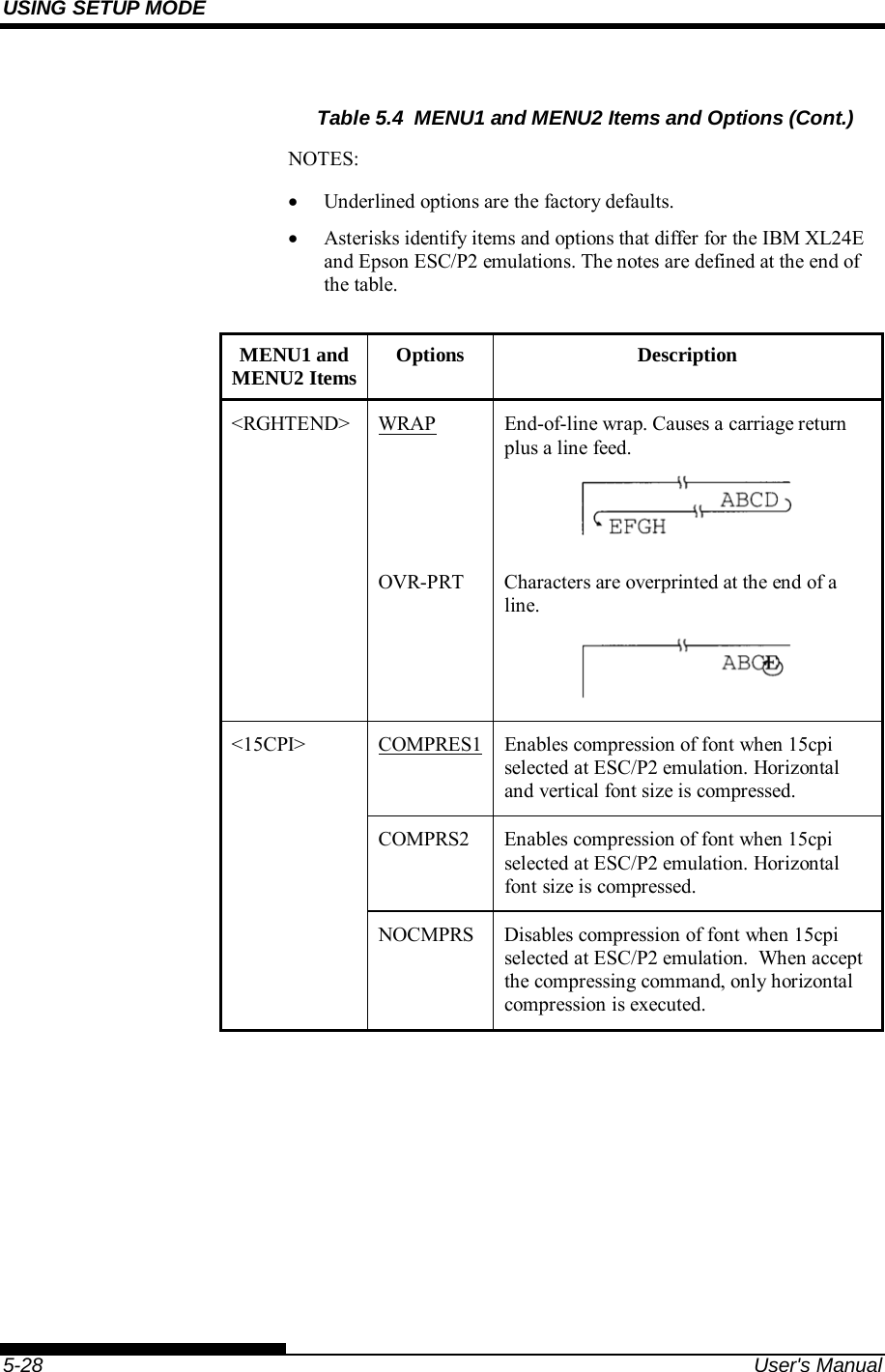
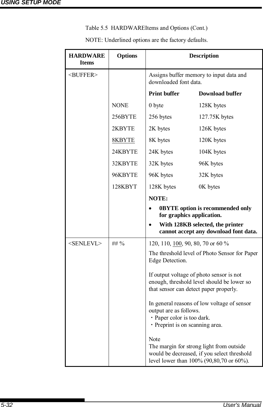
![USING SETUP MODE 5-38 User's Manual Table 5.6 ADJUST Items and Options (Cont.) NOTE: The top of form position is out of paper at [-1/6 IN] and [0/6 IN]. When printing, set the margin more than 1/6inch. ADJUST Items Options Description <FCUTORG> -1/6 IN 0/6 IN 1/6 IN 1.8/6 IN : 6/6 IN : 66/6 IN Sets the top-of-form for front single sheets in increments of 1/6 inch (4.2 mm) from the physical top of the page. The default is recommended if your top margin is not software-specified. A setting of 1/6 inch is preferable when your top margin is software-specified. <FCUTFIN> 0/180, ..., 29/180 Fine-tunes the top-of-form position for front single sheets. Increases top-of-form in increments of 1/180 inch (0.14 mm). <RCUTORG> -1/6 IN 0/6 IN 1/6 IN 1.8/6 IN : 6/6 IN : 66/6 IN Sets the top-of-form for rear single sheets in increments of 1/6 inch (4.2 mm) from the physical top of the page. The default is recommended if your top margin is not software-specified. A setting of 1/6 inch is preferable when your top margin is software-specified. <RCUTFIN> 0/180, ..., 29/180 Fine-tunes the top-of-form position for rear single sheets. Increases top-of-form in increments of 1/180 inch (0.14 mm).](https://usermanual.wiki/Fujitsu-Isotec/020M33335A/User-Guide-2859436-Page-132.png)


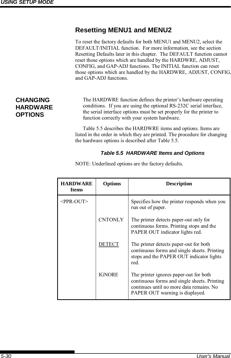
![COMMAND SETS User's Manual C-15 (d) w (Specify the width of the narrow bar of the bar code to be printed in units of 1/1440.) Specify the “Logical value” to be printed (in units of 1/1440). Actual printing: The printer prints with the width given in the following table in units of 1/180 inches. w Width of narrow bar 1 ~ 19 2 Dots (2/180 inches) 20 ~ 27 3 Dots (3/180 inches) 28 ~ 4 Dots (4/180 inches) (e) h (Specify the height of the bar code to be printed in units of 1/1440 taking the narrow bar width as the reference.) Height of bar code = (parameter w) (parameter h) [in units of 1/1440] Height of bar code 11 Inches Actual printing: The printing is done with the following initial values if the bar code height is less than or equal to 24 dots taking 1 dot equal to 1/180 inches of the printing unit of the printer. The following values are the standard heights for the respective bar code standards. Enter the value so that the height is ≤ 23/180 if the standard is correct. Narrow bar width EAN 13/UCP-A EAN 8 Others 2 Dots (16/1440) 162 Dots (1296/1440)130 Dots (1040/1040) 108 Dots (864/1440) 3 Dots (24/1440) 234 Dots (1872/1440)187 Dots (1496/1040) 135 Dots (1080/1440)4 Dots (32/1440) 312 Dots (2496/1440)249 Dots (1992/1040) 162 Dots (1296/1440) Figures in parentheses ( ) are values converted to units of 1/1440. ..](https://usermanual.wiki/Fujitsu-Isotec/020M33335A/User-Guide-2859436-Page-235.png)