Fujitsu Isotec 020M33335A Dot Matrix Printer User Manual
Fujitsu Isotec Limited Dot Matrix Printer
User Manual

FUJITSU DL7600Pro
DOT MATRIX PRINTER
USER'S MANUAL

READ THE ENTIRE MANUAL CAREFULLY BEFORE USING THIS PRODUCT.
INCORRECT USE OF THE PRODUCT MAY RESULT IN INJURY OR DAMAGE TO
USERS, BYSTANDERS OR PROPERTY.
While FUJITSU ISOTEC has sought to ensure the accuracy of all information in this manual,
FUJITSU ISOTEC assumes no liability to any party for any damage caused by any error or
omission contained in this manual, its updates or supplements, whether such errors or omissions
result from negligence, accident, or any other cause. In addition, FUJITSU ISOTEC assumes no
liability with respect to the application or use of any product or system in accordance with
descriptions or instructions contained herein; including any liability for incidental or
consequential damages arising therefrom. FUJITSU ISOTEC DISCLAIMS ALL WARRANTIES
REGARDING THE INFORMATION CONTAINED HEREIN, WHETHER EXPRESSED,
IMPLIED, OR STATUTORY.
FUJITSU ISOTEC reserves the right to make changes to any products described herein without
further notice and without obligation.
This Product is designed, developed and manufactured as contemplated for general use, including
without limitation, general office use, personal use, household use, and ordinary industrial use,
but is not designed, developed and manufactured as contemplated for use accompanying fatal
risks or dangers that, unless extremely high safety is secured, could lead directly to death,
personal injury, sever physical damage or other loss(hereinafter “High Safety Required Use”),
including without limitation, nuclear control in nuclear facility, aircraft flight control, air traffic
control, mass transport control, medical life support system, missile launch control in weapon
system. You shall not use this Product without securing the sufficient safety required for the High
Safety Required Use. If you wish to use this Product for High Safety Required Use, please
consult with our sales representatives in charge before such use.
This manual contains technology which is subject to the Foreign Exchange and Foreign Trade
Law of Japan. This manual should not be exported or transferred to foreign countries in any from
or method, or released to anyone other than the residents of Japan prior obtaining applicable
license from your local government or authorities and/ or the Ministry of Economy, Trade and
Industry of Japan in accordance with the above law.
IMPORTANT NOTE TO USERS
Using This Product in High-risk Situations
EXPORT CONTROL

User's Manual i
Following notes for United States are valid for
100-120V model only.
Federal Communications Commission
Radio Frequency Interference Statement
for United States Users
NOTE: This equipment has been tested and found to comply with the
limits for a Class B digital device, pursuant to Part 15B of the FCC Rules.
These limits are designed to provide reasonable protection against
harmful interference in a residential installation. This equipment
generates, uses, and can radiate radio frequency energy and, if not
installed and used in accordance with the instructions, may cause harmful
interference to radio communications. However, there is no guarantee
that interference will not occur in a particular installation. If this
equipment does cause harmful interference to radio or television
reception, which can be determined by turning the equipment off and on,
the user is encouraged to try to correct the interference by one or more of
the following measure:
Reorient or relocate the receiving antenna.
Increase the separation between the equipment and receiver.
Connect the equipment into an outlet on a circuit different from that
to which the receiver is connected.
Consult the dealer or an experienced radio/TV technician for help.
FCC warning: Changes or modifications not expressly approved by the
party responsible for compliance could void the user’s authority to
operate the equipment.
NOTES
1. Testing of this equipment was performed on model number
M33335A.
2. The use of an unshielded a non-shielded interface cable with the
referenced device is prohibited. The length of the parallel interface
cable must be 3 meters (10 feet) or less. The length of the optional
serial interface cable must be 15 meters (50 feet) or less.
3. The length of the power cord must be 3 meters (10 feet) or less.

ii User's Manual
The contents of this manual may be revised without prior notice and
without obligation to incorporate changes and improvements into units
already shipped.
Every effort has been made to ensure that the information included here
is complete and accurate at the time of publication; however, Fujitsu
Isotec Limited cannot be held responsible for errors and omissions.
Printer model specifications differ with the power supply input voltage
(M33335A; 100-120 V or M33335B; 220-240 V).
KA02087-Y890-01EN DECEMBER 2015
Copyright © 2015 FUJITSU ISOTEC LIMITED
Printed in Japan. All rights reserved. No part of this manual may be
reproduced or translated, stored in a database or retrieval system, or
transmitted, in any form or by any means, electronic, mechanical,
photocopying, recording, or otherwise, without the prior written
permission of Fujitsu Isotec Limited.
FUJITSU is a registered trademark and Fujitsu Creative Faces is a
trademark of Fujitsu Limited. Centronics is a trademark of Centronics
Data Computer Corporation. IBM PC and IBM Proprinter XL24E are
trademarks of International Business Machines Corporation. ESC/P2 is a
trademark of Seiko Epson Corporation. Microsoft is a registered
trademark and MS-DOS and Windows are trademarks of Microsoft
Corporation. Nimbus Sans is a registered trademark of URW
Unternehmensberatung Karow Rubow Weber GmbH, Hamburg.
Other product names mentioned in this manual may also be trademarks
of their respective companies.
TRADEMARK
ACKNOWLEDGEMENT

User's Manual iii
ABOUT THIS MANUAL
Thank you for buying the Fujitsu DL7600Pro dot matrix printer. You can
expect years of reliable service with very little maintenance. This manual
explains how to use your printer to full advantage. It is written for both
new and experienced printer users.
This manual describes how to install, set up, and use your printer and
printer options. It also explains how to keep the printer in good working
condition and what to do should something go wrong. Detailed
procedures are provided for first-time users. Experienced users can skip
some of the details, using the table of contents and chapter introductions
to locate information.
This manual has several appendixes, a glossary, and an index. Appendix
A lists supplies and additional documentation and information available
from your dealer or authorized Fujitsu representative. Fujitsu offices are
listed at the end of the manual.
This manual covers model DL7600Pro, a 136-column printer. Each
model has a 100-120 (M33335A) V or 220-240 (M33335B) V power
supply.
A LAN card, a user add-on option, can be installed only on printer
models with the Centronics parallel + USB interfaces. You must specify
these when purchasing the printer.
Other options include a cut sheet feeder can be added by yourself after
purchasing the printer.
DL7600Pro
Basic specifications
Print line at 10 cpi: 136 columns (DL7600Pro)
Control Panel: LED type
LCD type
Interface: Centronics parallel + RS-232C
Centronics parallel + USB + LAN (LAN user option)
Alternative specification
Power supply: 100-120 V (M33335A)
220-240 V (M33335B)
User add-on option
LAN card
Cut sheet feeder
Tractor unit
Sound proof cover
Large Stacker
Small paper table
cpi: characters per inch
PRINTER MODELS
AND OPTIONS

iv User's Manual
This manual is organized as follows:
Quick Reference summarizes everyday printer operations. After you
become familiar with the printer, use this section as a memory aid.
Chapter 1, Introduction, introduces the printer and identifies key
features and options that enhance the printer’s capabilities.
Chapter 2, Setting Up, gives step-by-step procedures for setting up the
printer for immediate use and identifies the main parts of the printer. If
this is your first printer, you should read the entire chapter before
attempting to use the printer.
Chapter 3, Paper Handling, explains how to load and use paper with
your printer.
Chapter 4, Printing, covers basic printing operations. This chapter
describes everyday operations from the printer’s control panel, such as
loading paper and selecting print features, in detail. After you become
more familiar with the printer, use Quick Reference at the beginning of
the manual to refresh your memory as needed.
Chapter 5, Using Setup Mode, describes how to change the printer’s
optional settings, such as print features, hardware options, and top-of-
form. Most settings only affect print features such as the typestyle and
page format. Note that certain settings directly affect hardware and
software compatibility. Refer to this chapter as indicated in Chapter 2 or
as required.
Chapter 6, Maintenance, explains basic maintenance procedures for
this printer.
Chapter 7, Trouble-Shooting, describes problem-solving techniques.
Before you contact your dealer for help, check the list of problems and
solutions provided in this chapter.
Chapter 8, Installing Options, describes the options available for the
printer and explains how to install them.
At the end of this manual, you will find several appendixes, a glossary,
and an index. Appendix A gives order numbers for printer supplies,
options, and publications. Other appendixes provide additional technical
information about the printer.
ORGANIZATION

User's Manual v
Special information, such as warnings, cautions, and notes, are indicated
as follows:
WARNING
A WARNING indicates that personal injury may result if you do not
follow a procedure correctly.
CAUTION
A CAUTION indicates that damage to the printer may result if you do not
follow a procedure correctly.
NOTE
A NOTE provides “how-to” tips or suggestions to help you perform
a procedure correctly. NOTEs are particularly useful for first-time
users.
For Experienced Users:
If you are familiar with this printer or with dot matrix printers in general,
this information will help you use the manual effectively.
CONVENTIONS
viii User's Manual
Warning symbols
Various graphic symbols are used in this manual. They serve as signs to help users of this product use
the product safely and correctly as well as prevent damage and personal injury to the users or bystanders.
The following tables show and explain each symbol. Be sure that you understand the meaning of each
symbol before reading the manual.
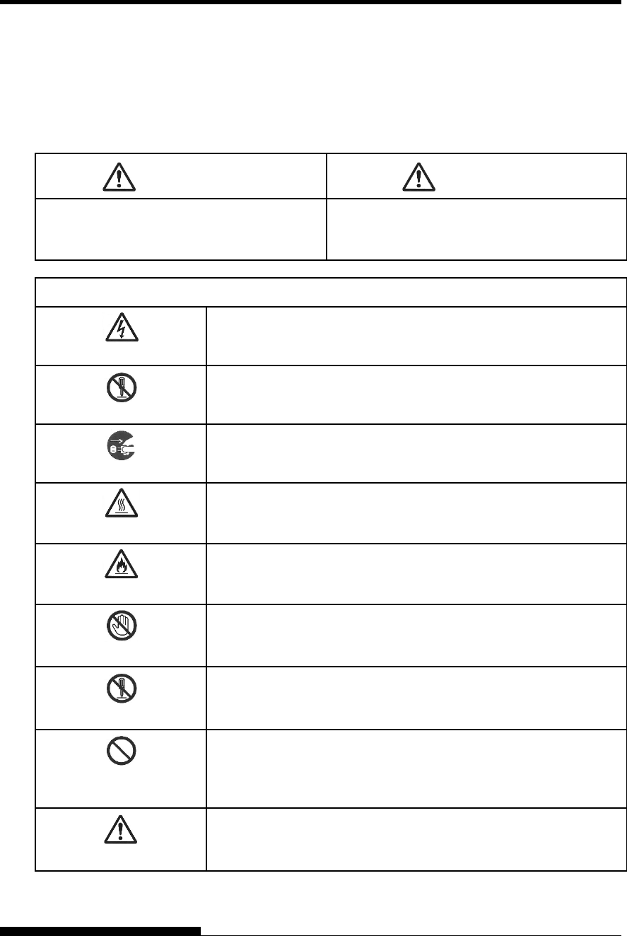
WARNING CAUTION
A WARNING indicates that death or serious
personal injury may result if you do not follow a
procedure correctly.
A CAUTION indicates that personal injury or
property damage may result if you do not follow a
procedure correctly.
Examples and explanations of graphic symbols
Indicates a warning or caution item. By itself, the image in this
symbol suggests the meaning of the warning or caution (the example
on the left is a caution of possible electric shock).
Indicates a prohibited action. The image in or beside this symbol
expresses the prohibited action (the example on the left indicates that
disassembly is prohibited).
Indicates a direction that must be observed. The image in this
symbol shows the direction (the example on the left shows the
direction in which a power plug is disconnected from an outlet).
Caution: Hot
This symbol and accompanying statement indicate a risk of injury from
a hot object.
Caution: Flammable
This symbol and accompanying statement indicate a risk of fire.
Do not touch
This symbol and accompanying statement indicate a risk of injury from
touching part of the equipment.
Do not disassemble
This symbol and accompanying statement indicate a risk of injury,
such as from electric shock, caused by disassembling the equipment.
General prohibited
action
This symbol and accompanying statement indicate a general prohibited
action.
General caution
This symbol and accompanying statement indicate a general caution.
User's Manual ix
Notes on Safety
WARNING
WARNING
Do not place a container containing water, such as a vase, potted plant, and drinking glass,
or a metal object on or near the printer.
Otherwise, electric shock or fire may result.
Do not place the printer in a humid or dusty area, in an area with explosive fumes, an area
with poor ventilation or close to a fire.
Otherwise, electric shock or fire may result.
Use only one of the power cords included with this product, for this product. Do not use
any other power cord for this product.
Otherwise, electric shock or fire may result.
Do not use this product in an area exposed to a high level of moisture, such as a bathroom
and shower room.
Otherwise, electric shock or fire may result.
x User's Manual
WARNING
When mounting or removing an optional device or component, turn off the power to the
printer and personal computer and disconnect their power plugs from the outlets before
performing the work.
Otherwise, electric shock may result.
Connect only Fujitsu-recommended optional devices and components.
Otherwise, electric shock, fire, or failure may result.
CAUTION
Do not block openings in the printer (e.g., ventilation openings).
If ventilation openings are blocked, heat accumulates inside the printer, possibly resulting
in a fire.
Do not place a heavy object on the printer. Also, do not subject the printer to shocks.
Otherwise, the printer may become unbalanced, causing it to fall, and possibly resulting in
personal injury.
Do not place the printer in an area exposed to strong vibration or an unstable area such as
on a slope.
Otherwise, the printer may fall or topple, possibly resulting in personal injury.
Do not leave the printer in an area exposed to direct sunlight for a long time, such as inside
a car under the sun or any other area subjected to high temperatures.
Otherwise, the printer surface heats up, possibly melting covers or resulting in other
deformities, or the inside of the printer may become extremely hot, possibly resulting in
fire.
Before moving the printer, be sure to disconnect the power plug from the outlet and
disconnect all connected cables from the printer.
Otherwise, the power cord may be damaged, possibly resulting in electric shock or fire, or
the printer may fall or topple, possibly resulting in personal injury.
Before connecting or disconnecting a printer cable, be sure to turn off the power to the
printer and personal computer.
Performing that and related work without the power turned off may result in a personal
computer or printer failure.
User's Manual xi
Notes about the printer in operation
WARNING
If the printer is making a strange noise, which indicates a problem, discontinue printer
operation. Request your printer dealer to fix the problem.
Continued operation of the printer without repairs may result in electric shock or fire.
Do not use a power source whose voltage is other than that indicated. Also, an excessive
number of plugged-in power cords must not be connected to a single outlet.
Otherwise, electric shock or fire may result.
Do not spill any liquid, such as water, on the printer.
Otherwise, electric shock or fire may result.
Do not damage or modify the power cord.
The power cord may be damaged by placing a heavy object on it, stretching it excessively,
forcibly bending it, twisting it, or heating it, and this may result in electric shock or fire.
Do not use the power cord if it or the power plug is damaged or the plug does not fit
securely in the outlet receptacle.
Using the power cord in that condition may result in electric shock or fire.
Do not insert the power cord into an outlet or turn on the power to the printer when any of
its covers has been removed.
Otherwise, electric shock or fire may result.
Prevent foreign objects, such as metal shards and inflammable materials, from being
inserted or dropped into any openings in the printer (e.g., ventilation openings).
Otherwise, electric shock or fire may result.
Do not disconnect the power plug from the outlet while the power to the printer is turned
on.
Otherwise, the plug becomes deformed, possibly resulting in fire.
Do not remove the main printer cover or the cover for the cable connectors except as
necessary. To check and repair internal components, request your printer dealer to do so.
Some internal components use high voltage, and touching them may result in electric
shock.
Do not modify the printer by yourself.
Otherwise, electric shock or fire may result.
Do not connect or disconnect the power plug with wet hands.
Otherwise, electric shock may result.
xii User's Manual
WARNING
If excessive heat, smoke, a strange odor, or a strange noise is coming the printer or any
other abnormality is observed, immediately turn off the power to the printer by using the
power switch, and be sure to disconnect the power plug from the outlet.
Then, after verifying the end of the abnormality (e.g., no more smoke is coming from the
printer), request your printer dealer to make repairs. Do not repair the printer by yourself
as doing so is dangerous.
Continued use of the printer when it is operating abnormally may result in electric shock or
fire.
If a foreign object (e.g., water or other liquid, metal shard) has entered the printer,
immediately turn off the power to the printer by using the power switch, and disconnect the
power plug from the outlet. Then, contact your printer dealer.
Continued use of the printer in that condition may result in electric shock or fire.
Customers who use the printer near children should take especial care regarding this point.
If the printer is dropped or a cover is damaged, turn off the power to the printer by using
the power switch, and disconnect the power plug from the outlet. Then, contact your
printer dealer.
Continued use of printer in that condition may result in electric shock or fire.
Before performing cleaning, maintenance, or troubleshooting work on the printer, switch
off the power switch, and be sure to disconnect the power plug from the outlet.
Performing that work on the printer without the power turned off may result in burns or
electric shock.
If dust accumulates on or near the metal parts of the power plug, so wipe away that dust
with a dry cloth.
Continued use of printer in that condition may result in fire.
Do not drop or strike the printer, such as by hitting it against something.
Otherwise, a failure may result.
User's Manual xiii
CAUTION
Insert the power plug completely into an outlet so that it is securely connected.
Otherwise, electric shock or fire may result.
Exercise caution to keep loose clothing, hair, neckties, etc. away from paper feed- or
ejection openings, and tractors while the printer is operating.
Otherwise, personal injury may result.
When disconnecting the power plug from the outlet, pull it out while grasping the plug, not
the cord.
If you pull it out while grasping the cord, the insulation may be damaged or the cable core
may be exposed or damaged, possibly resulting in electric shock or fire.
Do not cover or wrap the printer with a cloth or anything else while it is operating.
Otherwise, heat accumulates, possibly resulting in fire.
Do not use the power cord with it bunched together.
Otherwise, heat accumulates, possibly resulting in fire.
If the printer operates when the front cover is unclosed, immediately turn the printer off,
and unplug the power code from wall outlet.
Then contact your printer dealer to make repair of safety interlock.
Continued use of the printer in that condition, operation of the mechanism inside of the
front cover may become a cause of an injury.
If the printer is not to be used for a long time, disconnect the power plug from the outlet
for safety reasons.
Otherwise, electric shock or fire may result.
If a lightning storm is in nearby, disconnect the power plug from the outlet.
Leaving the plug connected to the outlet may result in damage to the printer or other
property damage.
The print head and internal frames become extremely hot during printer operation and
remain so immediately afterwards. Do not touch these parts until sufficient time has
passed to allow them to cool.
Otherwise, burns or personal injury may result.
xiv User's Manual
CAUTION
Do not touch the paper feed- or ejection openings while the printer is operating.
Otherwise, personal injury may be result.
Do not touch the printer cable connectors or the metal part of the print head.
Otherwise, personal injury or a printer failure may result.
Do not touch the print head while it is moving.
Otherwise, burns or personal injury may result.
Note that continuous forms that are fed in the reverse direction continuously may come off
the paper feed tractors.
Operate the printer with the paper thickness set to the appropriate paper thickness.
Use only an original ribbon cassette that is specified as suitable by Fujitsu.
Textile fibers accumulate on components inside the printer and parts of the roller, so clean
these parts regularly.
Do not turn the ribbon feed knob in the reverse direction.
Otherwise, the ribbon may become jammed and stuck.
If printing is started with a slack ribbon, the ribbon may become tangled or the ribbon feed
mechanism may become locked.
The print head is extremely hot immediately after printing. When replacing the ribbon,
verify that the print head is sufficiently cool before setting the print head to the ribbon
replacement position.

User's Manual xv
TABLE OF CONTENTS
QUICK REFERENCE .........................................................1
CHAPTER 1 INTRODUCTION ....................................................................... 1-1
FEATURES ................................................................... 1-1
MODELS ....................................................................... 1-3
OPTIONS ...................................................................... 1-3
CHAPTER 2 SETTING UP............................................................................. 2-1
SELECTING A GOOD LOCATION ................................. 2-1
UNPACKING THE PRINTER ......................................... 2-2
Checking Options and Supplies ................................. 2-4
ASSEMBLING THE PRINTER ....................................... 2-5
Handling the paper table ........................................... 2-5
Installing the Ribbon cartridge ................................... 2-7
Mounting and removing the tractor unit .....................2-12
GETTING ACQUAINTED WITH YOUR PRINTER .........2-15
CONNECTING THE POWER CORD ............................2-18
TESTING THE PRINTER (OFFLINE) ............................2-19
Loading Paper for the Self-Test ................................2-19
Printing the Self-Test ................................................2-19
CONNECTING THE PRINTER TO YOUR
COMPUTER .................................................................2-22
Selecting a Parallel Interface Cable ..........................2-22
Selecting a Serial Interface Cable.............................2-22
Selecting a USB Cable .............................................2-23
Selecting a LAN cable ..............................................2-23
Connecting the Interface Cable ................................2-23
SELECTING AN EMULATION ......................................2-24
PRINTING A SAMPLE PAGE (ONLINE) .......................2-27
INSTALLING THE PRINTER DRIVER...........................2-29
CHAPTER 3 PAPER HANDLING .................................................................. 3-1
SELECTING PAPER...................................................... 3-1
OVERVIEW OF PAPER OPERATIONS ......................... 3-2
SELECTING PAPER PATH ........................................... 3-5
Paper Paths and Feed Directions .............................. 3-5
ADJUSTING FOR PAPER THICKNESS (LED) .............. 3-9
ADJUSTING FOR PAPER THICKNESS (LCD) .............3-10
USING CONTINUOUS FORMS ....................................3-11
Positioning the Paper Stack .....................................3-11
Loading Continuous Forms (Front Feed) ..................3-12
Loading Continuous Forms (Rear Feed) ...................3-15
Unloading Continuous Forms ...................................3-17
Tearing Off Continuous Forms .................................3-17
USING SINGLE SHEETS .............................................3-19
Loading a Paper From The Paper Table. ..................3-19
Loading Paper from the Cut Sheet Feeder ...............3-22
(Option)....................................................................3-22
Ejecting Single Sheets .............................................3-24

xvi User's Manual
FEEDING AND POSITIONING PAPER ......................... 3-25
Line Feed/Form Feed .............................................. 3-25
Micro Feed............................................................... 3-25
Load Position Adjust ................................................ 3-25
TIPS ON PAPER HANDLING ....................................... 3-27
General Tips ............................................................ 3-27
Multipart Forms ........................................................ 3-27
Envelopes ................................................................ 3-27
Labels ...................................................................... 3-27
CHAPTER 4 PRINTING ................................................................................. 4-1
MULTIPART FORMS (HI IMPACT MODE) ..................... 4-1
PRINT MODE(HI SPEED MODE/QUIET MODE) ............ 4-2
STARTING OR STOPPING PRINTING ........................... 4-3
Starting Printing ......................................................... 4-3
Stopping Printing ....................................................... 4-3
Resuming from a Paper-Out ...................................... 4-3
Printing the remaining lines on a page ........................ 4-3
Continuing printing after supplying paper.................... 4-4
REMOVING PRINTED PAGES ....................................... 4-5
Removing Single Sheets ............................................ 4-5
Removing Continuous Forms ..................................... 4-5
CLEARING THE PRINT BUFFER ................................... 4-5
SELECTING PRINT FEATURES .................................... 4-6
Using Commercial Software ....................................... 4-6
Using the Control Panel ............................................. 4-7
Selecting MENU1 or MENU2 ..................................... 4-8
Using the Control Panel (LCD type only) .................... 4-9
CHAPTER 5 USING SETUP MODE .............................................................. 5-1
HOW TO USE THIS CHAPTER ...................................... 5-1
ENTERING SETUP MODE(LED) .................................... 5-2
OVERVIEW OF SETUP MODE (LED) ............................ 5-4
Setup Mode Example (LED) ....................................... 5-5
Points to Remember .................................................. 5-7
PRINTING A LIST OF SELECTED OPTIONS(LED) ........ 5-7
ENTERING SETUP MODE(LCD) .................................. 5-10
Setup Mode Example (LCD) .................................... 5-11
OVERVIEW OF SETUP MODE (LCD) .......................... 5-12
PRINTING A LIST OF SELECTED OPTIONS(LCD) ...... 5-12
DECIDING WHICH OPTIONS TO CHANGE ................. 5-13
MENU1 AND MENU2 ITEMS AND OPTIONS ............... 5-15
Resetting MENU1 and MENU2 ................................ 5-30
CHANGING HARDWARE OPTIONS ............................ 5-30
CHANGING PRINT POSITION ADJUSTMENT
OPTIONS ..................................................................... 5-36
CHANGING CONFIGURATION OPTIONS ................... 5-45
HEAD GAP ADJUSTMENT ITEMS AND OPTIONS ...... 5-58
EXITING AND SAVING................................................. 5-59
Procedure (for LED type) ......................................... 5-59
Procedure (for LCD type) ......................................... 5-59
RESETTING DEFAULTS .............................................. 5-60
Resetting Power-On Defaults ................................... 5-60

User's Manual xvii
Resetting Factory Defaults .......................................5-60
Resetting Factory Defaults in MENU1 and MENU2 ..5-60
Procedure (for LED type) .........................................5-60
Procedure (for LCD type) .........................................5-61
USING THE DIAGNOSTIC FUNCTIONS ......................5-62
Printing the Self-Test ................................................5-62
Procedure ................................................................5-62
Printing Hex Dumps .................................................5-64
Procedure ................................................................5-64
Checking Vertical Print Alignment (V-ALMNT) ..........5-66
Procedure ................................................................5-66
SETUP MODE REFERENCE ........................................5-69
DPL24C PLUS ORGANIZATION .............................5-70
................................................................................5-72
Differences in IBM Proprinter XL24E Emulation ........5-73
Differences in Epson ESC/P2 Emulation ..................5-73
ONLINE SETUP MODE ................................................5-74
CHAPTER 6 MAINTENANCE ........................................................................ 6-1
CLEANING .................................................................... 6-1
Cleaning and Vacuuming the Printer ......................... 6-1
Cleaning the Platen ................................................... 6-2
REPLACING THE RIBBON ............................................ 6-3
OPENING AND CLOSING THE CONTROL PANEL ....... 6-8
REMOVING THE STACKER UNIT ................................. 6-8
MOUNTING THE STACKER UNIT ................................. 6-9
CHAPTER 7 TROUBLE-SHOOTING ............................................................ 7-1
SOLVING PROBLEMS .................................................. 7-1
Print Quality Problems............................................... 7-1
Paper Handling Problems ......................................... 7-5
Operating Problems .................................................. 7-7
Printer Failures.......................................................... 7-8
Alarm display function(LED) ...................................... 7-9
Alarm display function(LCD) .....................................7-10
Responses to alarm occurrences .............................7-11
DIAGNOSTIC FUNCTIONS ..........................................7-11
GETTING HELP ...........................................................7-12
CHAPTER 8 INSTALLING OPTIONS ........................................................... 8-1
INSTALLING THE LAN card .......................................... 8-1
INSTALLING THE CUT SHEET FEEDER ...................... 8-3
Installing on the front side of the printer ..................... 8-3
Installing on the rear side of the printer ...................... 8-6
Removing the Cut Sheet Feeder ............................... 8-9
INSTALLING THE TRACTOR UNIT ..............................8-10
INSTALLING THE LARGE STACKER ...........................8-11
INSTALLING THE SMALL PAPER TABLE ....................8-13
INSTALLING THE SOUND PROOF COVER .................8-15
APPENDIX A SUPPLIES AND OPTIONS....................................................... A-1
SUPPLIES ..................................................................... A-1

xviii User's Manual
OPTIONS ...................................................................... A-1
APPENDIX B PRINTER AND PAPER SPECIFICATIONS ............................. B-1
PHYSICAL SPECIFICATIONS ....................................... B-1
FUNCTIONAL SPECIFICATIONS .................................. B-3
PERFORMANCE SPECIFICATIONS ............................. B-6
PAPER SPECIFICATIONS ............................................ B-8
Paper Thickness ..................................................... B-10
APPENDIX C COMMAND SETS .................................................................... C-1
FUJITSU DPL24C PLUS ............................................... C-2
Bar Code Printing Control ....................................... C-14
IBM PROPRINTER XL24E EMULATION ..................... C-22
EPSON ESC/P2 EMULATION ..................................... C-28
APPENDIX D INTERFACE INFORMATION ................................................... D-1
PARALLEL INTERFACE ................................................ D-1
Compatible Mode ...................................................... D-2
Nibble Mode ............................................................. D-4
Data Transmission Timing......................................... D-6
SERIAL INTERFACE ..................................................... D-7
Serial Options ........................................................... D-8
Cable Wiring ............................................................. D-8
Serial Protocols....................................................... D-10
USB INTERFACE ........................................................ D-11
Cable ...................................................................... D-11
Specification ........................................................... D-11
LAN INTERFACE ........................................................ D-12
APPENDIX E CHARACTER SETS ................................................................. E-1
CHARACTER SETS 1 AND 2
(DPL24C PLUS AND IBM XL24E EMULATION) ........... E-1
ITALIC AND GRAPHICS CHARACTER SETS
(ESC/P2 EMULATION) .................................................. E-2
NATIONAL CHARACTER SETS
(ALLEMULATIONS) ....................................................... E-4
NATIONAL CHARACTER SETS
(DPL24C PLUS AND IBM XL24E EMULATION) . ........ E-15
NATIONAL CHARACTER SETS
(ESC/P2 EMULATION) ................................................ E-17
NATIONAL CHARACTER SETS AND SUPPORTED
RESIDENT FONTS (ALL EMULATIONS)...................... E20
APPENDIX F RESIDENT FONTS .................................................................... F1
INDEX ................................................................................................ IN-1
FUJITSU OFFICES ....................................................................................................................... 1
User's Manual QR-1
Q
QUICK REFERENCE
QUICK REFERENCE
Quick Reference is written for experienced users —
users who are familiar with how the printer works,
but who may need to refresh their memory
occasionally. Only the printer’s normal (non-setup)
mode is covered. For details on setup mode, see Chapter 5.
Normal mode operation includes everyday operations, such as paper
handling and font selection. The printer comes up in normal mode when
turned on.
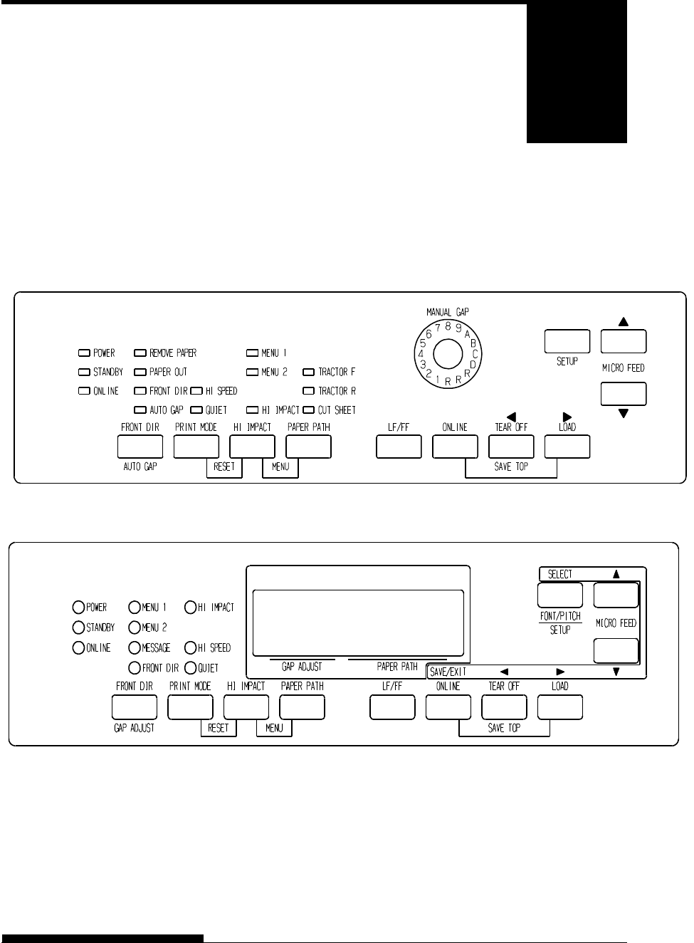
LED type Control panel
LCD type Control panel
The table on the next page lists normal mode operations with online and
offline conditions and gives the required user response.
Operations are listed by functions.
QUICK REFERENCE
QR-2 User's Manual
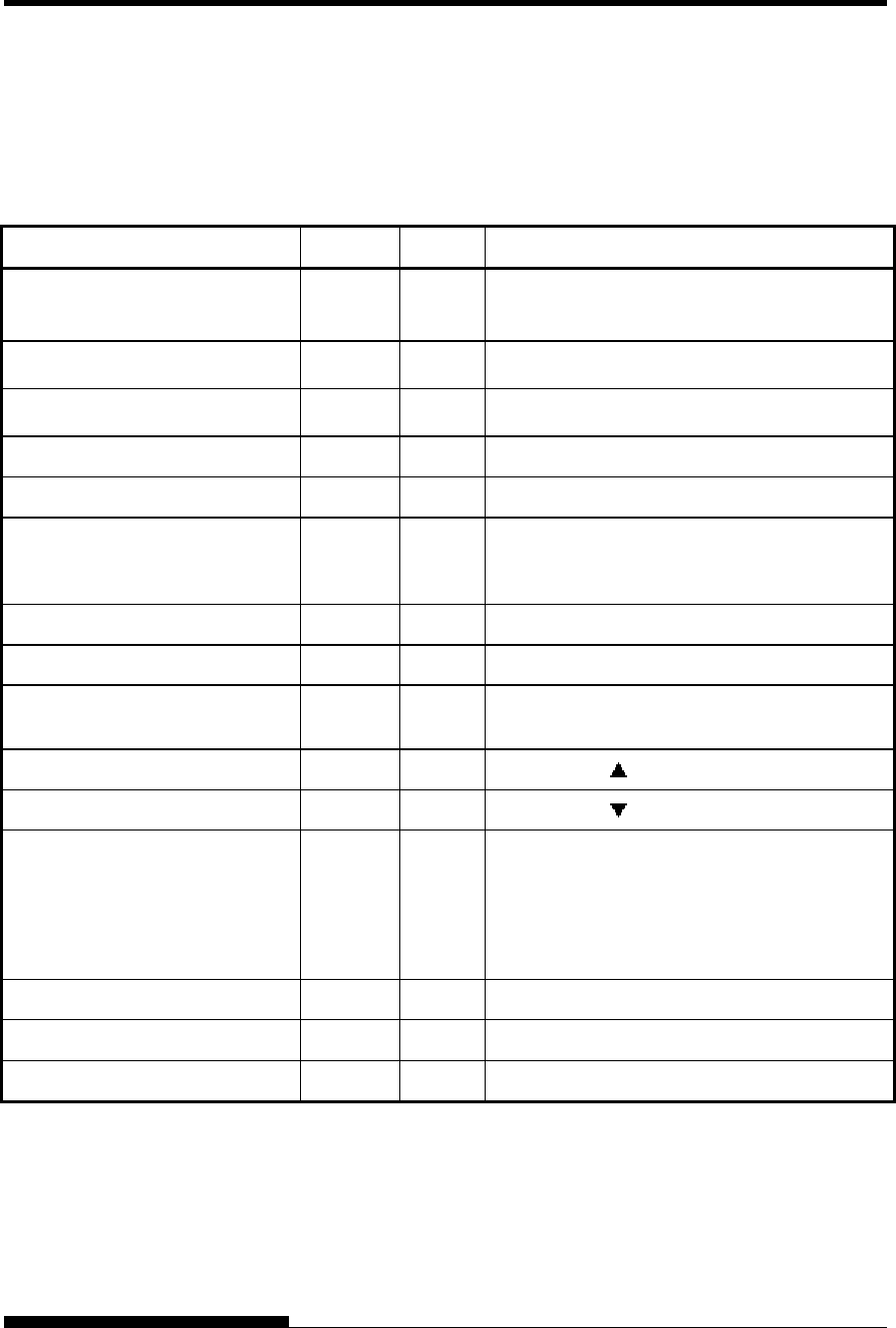
Printer Operations (Normal Mode)
: Operation can be performed when the printer is in this state.
— : Operation cannot be performed when the printer is in this state.
N/A: Does not apply.
Operation Online Offline Required Response
Enter normal mode N/A N/A Turn printer on. (Press I on the power switch.)
If STANDBY lamp lights, Press any buttons.
Place printer offlin
e
(Stop printing)
— Press ONLINE.
So that ONLINE lamp is off.
Place printer onlin
e
(Start printing) — Press ONLINE.
So that ONLINE lamp lights.
Load paper Press LOAD.
Line feed (forward) Press LF/FF within three seconds.
Unload paper to park position
(both front and rear-fed
continuous forms)
Press LOAD.
Form feed (forward) Press and hold LF/FF until the operation starts.
Eject single sheets Press and hold LF/FF until the operation starts.
Tear off forms
(continuous forms only)
Press TEAR OFF. Tear off forms, then press
any button to retract forms.
Micro feed (backward) Press MICRO .
Micro feed (forward) Press MICRO .
Select a direction from which cut
sheet is ejected.
— Press FRONT DIR.
When FRONT DIR lamp lights, cut sheet is
ejected to the front side.
When FRONT DIR lamp is off, cut sheet is
ejected to the rear side.
Select a print mode Press PRINT MODE.
Set/reset high impact mode Press HI IMPACT.
Select a paper input source Press PAPER PATH.
QUICK REFERENCE
User's Manual QR-3
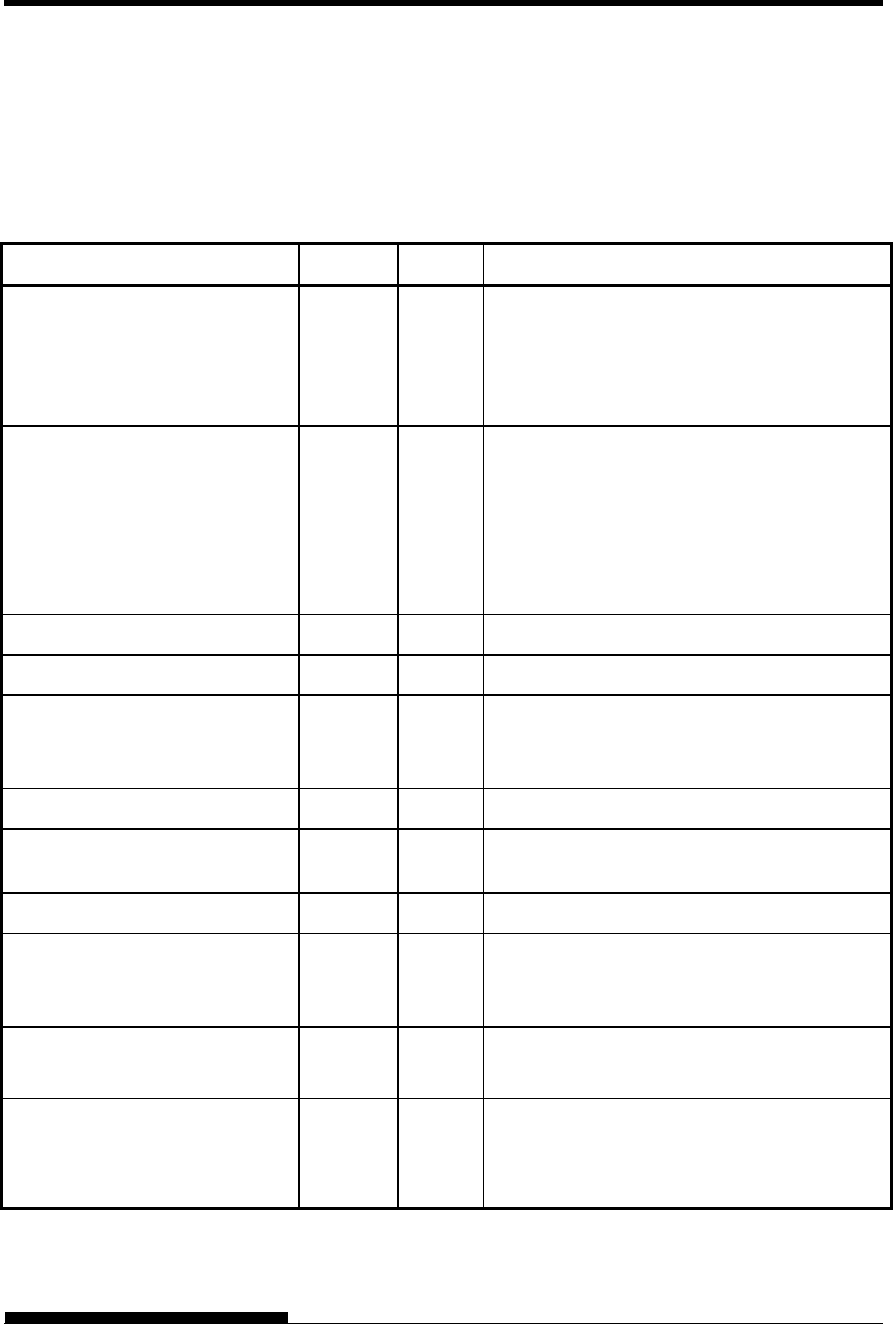
Printer Operations (Normal Mode) (Cont.)
: Operation can be performed when the printer is in this state.
— : Operation cannot be performed when the printer is in this state.
N/A: Does not apply.
Operation Online Offline Required Response
Select auto adjusting for paper
thickness.
(LED type)
Press AUTO GAP 2 second or more.
So that AUTO GAP lamp lights
(LCD type)
Press GAP ADJUST.
So that LCD display “AUTO”
Adjust for paper thickness
manually
(LED type)
Press AUTO GAP 2 second or more.
So that AUTO GAP lamp is off.
Then manual gap dial become effective.
(LCD type)
Press GAP ADJUST repeatedly.
So that LCD display
“GAP-1~GAP9,GAP-A~GAP-D
Save adjusted load positions Press ONLINE and LOAD.
Select MENU1 or MENU2 — Press PAPER PATH and HI IMPACT.
Clear print buffer — (LED type)
Press FRONT DIR and AUTO GAP.
(LCD type)
Press HI IMPACT and PRINT MODE.
Reset power-on defaults Turn printer off, then on.
Start/stop/resume printing Start: Send print command.
Stop/resume: Press ONLINE.
Resume printing after paper — Press ONLINE.
Enter setup mode — (LED type)
Press SET UP .
(LCD type)
Press SET UP.
Enter font/pitch/quality
Setting mode
— (LCD type only)
Press FONT/PITCH.
Exit to normal mode
Self-test printing
Start: Turn printer off. Press LF/FF while
turning printer on.
Pause/resume: Press LOAD.
Exit: Press ONLINE.
User's Manual 1-1
1
CHAPTER 1 INTRODUCTION
INTRODUCTION
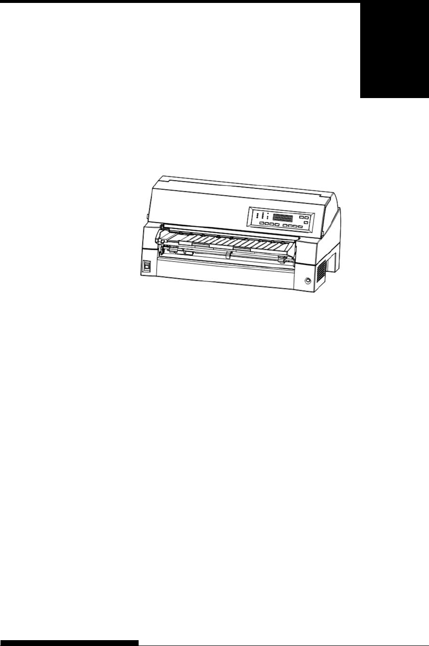
Congratulations on purchasing this printer. This
printer is a compact, versatile, flat paper path
printer that offers maximum compatibility with
today’s software packages and personal computers.
The 24-wire print head provides crisp, clear printing for business, office,
and home environments. This printer is also easy to install and use.
DL7600Pro dot matrix printer (136 columns)
Key printer features, models and options are listed in the next two
sections.
Software compatibility. This printer, which operates primarily with
the Fujitsu DPL24C PLUS command set, is compatible with the
IBM Proprinter XL24E command set and the Epson ESC/P2
command set.
Various character sets. As basic character sets, IBM PC character
sets 1 and 2 are available for the Fujitsu DPL24C PLUS command
set and the IBM Proprinter XL24E emulation, and the italic
character set and graphics character sets 1 and 2 are available for the
Epson ESC/P2 emulation. As national character sets, a total of 56 or
58 national character sets (depending on the emulation), including
IBM PS/2 character sets, are available.
Multiple fonts. The printer has nineteen resident fonts: Ten bit-map
fonts — Courier 10, Pica 10, Prestige Elite 12, Boldface PS, OCR-B
10, OCR-A 10, Correspondence, Compressed, Draft, and High-
speed Draft and nine outline fonts — Timeless, Nimbus Sans, and
Courier, each in upright, italic, and bold.
High-speed printing. At 10 cpi, print speed ranges from 180 cps for
letter quality to 800 cps for Super high draft quality.
FEATURES

INTRODUCTION
1-2 User's Manual
Large print buffer. 128K bytes are available in total for storing
input data and downloading fonts. A large input data buffer allows
you to send files to the printer and return to work in your application.
A large download buffer allows you to use custom fonts.
136-column print line. 136-column printers print in landscape mode
using legal- or standard-size computer forms.
Simple switching of paper types. The ability to “park” continuous
forms makes it easy to switch between continuous forms and single
sheets from the control panel. This switching is possible even for an
optional cut sheet feeder and second tractor.
Dual tractor feeding capability. The tractor unit is removable and
can be converted to front-feed or rear-feed.
Multi-path of paper. The printer has multiple paths to feed paper :
For the continuous form front and rear tractor(second tractor is
option), For cut sheet loading paper table (front), front csf(option),
rear csf(option).Also for cut sheet ejecting front and rear is
selectable(front eject paper require removing for next paper loading)
Tear off function. Available at both the front and the rear of the
printer. TEAR OFF button on the control panel is used.
High copy capability
Up to nine sheets for front/rear continuous forms and cut sheets
fed from front paper table.
Up to five sheets for CSF fed
Auto paper thickness control. Features as standard equipment.
Auto interface selection. The printer automatically selects the
interface proper to the occasion.
Paper skew detection. The printer detects a skew of paper that is
manually fed from the paper table and automatically ejects it without
printing.
Area-over print prevention. The printer senses and memorizes the
left and right edges of paper when loading the paper. If receiving
data beyond either edge, the printer ignores it to prevent breakage of
wires of print head.
Left Margin adjustment. The printer senses and memorizes the left
and right edges of paper when loading the paper. Printer adjusts the
left margin according to paper left edge. This function allows you
inaccurate paper setting. Would you use set-up mode to select this
function.
Maintenance-free. The printer only requires periodic cleaning and
changing of the ribbon cartridge.
INTRODUCTION
User's Manual 1-3
Power Supply type; 100-120 V input (M33335A)
220-240 V input (M33335B)
Interface type; Centronics parallel + USB interfaces
Centronics parallel + RS232C serial interface
Control panel type; LED type.
LCD type.
Printer add-on options are listed below. For details, see Chapter 8.
Cut sheet feeder. The SF940 single-bin feeder is available as an
option. Two cut sheet feeders can be installed in front of and behind
the printer at the same time. A cut sheet feeder allows single cut
sheets and multiple-part cut sheets to be fed automatically.
Tractor unit. A second tractor unit may be bought as an additional
option if dual tractor feeding capability is required.
LAN card. A LAN card is available as a printer add-on option. A
user installable function, the LAN card can be installed only on
printer models with the Centronics parallel + USB interfaces. For
details, see Chapter 8.
OPTIONS of DL7600Pro dot matrix printer
Small paper table. It is used in printing a short cut sheet.
MODELS
OPTIONS
SF940 single-bin feeder (front).
SF940 single-bin feeder (rear).
Tractor unit (rear)
Slot for LAN card is available.
(Centronics parallel + USB interfaces MODEL)
Replacing stacker with large stacker is required
when SF940 is installed in rear side.
INTRODUCTION
1-4 User's Manual
Large stacker. The large stacker accommodates sheets output from
the rear. It is used in continuous printing with a cut sheet feeder.
Sound proof cover. The acoustic noise is reduced.
OPTIONS of DL7600Pro dot matrix printer
Large stacker
Sound proof cover
Small paper table

User's Manual 2-1
2
CHAPTER 2 SETTING UP
SETTING UP
Your new printer is easy to install and set up.
This chapter tells you how to set up the printer
and start printing right away. If this is your first
printer, you should read the entire chapter before
attempting to use the printer.
In this chapter, you will learn how to:
Unpack, assemble, and select a good location for the printer
Identify the printer’s major parts
Connect the power and interface cables
Test the printer before connecting it to your computer
Install the printer driver
Select an emulation and print a sample page using your software
If you have a problem while setting up the printer, review the section
Solving Problems in Chapter 7. If the problem persists, contact your
dealer.
This printer is suitable for most business, office, and home environments.
To obtain peak performance from the printer, select a location that meets
the following guidelines:
Place the printer on a sturdy, level surface.
Place the printer near a well-grounded AC power outlet.
Ensure easy access to the front and rear of the printer by leaving
several inches of space around the printer. Do not block the air
vents on the front, left, and right sides of the printer.
Do not place the printer in direct sunlight or near heaters.
Make sure that the room is well-ventilated and free from
excessive dust.
Do not expose the printer to extremes of temperature and
humidity.
SELECTING A GOOD
LOCATION
SETTING UP
2-2 User's Manual
Use only the power cord supplied with the printer or
recommended by your dealer. Do not use an extension cord.
Do not plug the printer into a power outlet that is shared with
heavy industrial equipment, such as motors, or appliances, or
such as copiers or coffee makers. Such equipment often emits
electrical noise or causes power degradation.
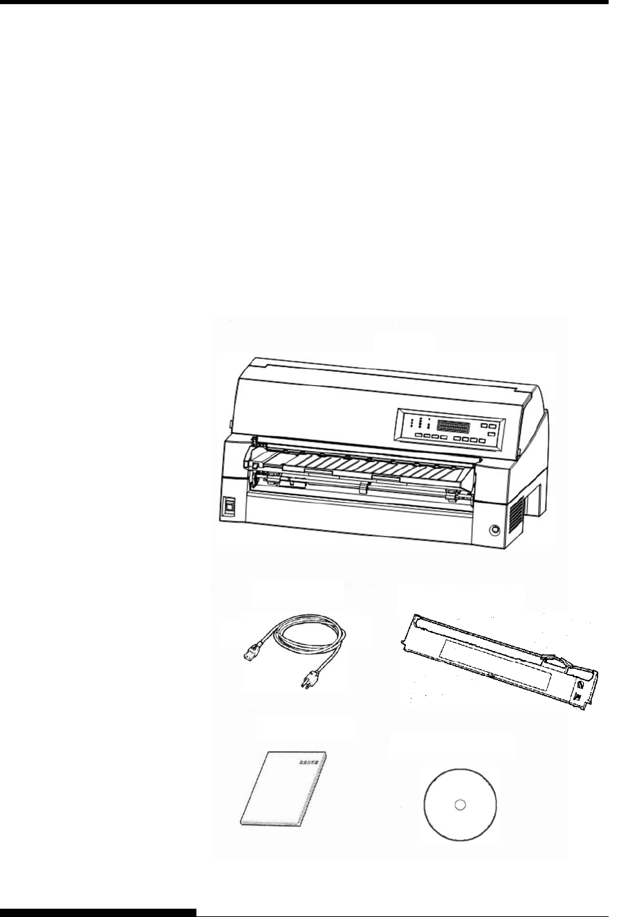
Unpack the printer as follows:
1. Open the carton and remove the printer and its components.
Make sure that you have all of the items shown below. Note that
the power cord supplied depends on the printer model (100-120
V or 220-240 V power supply).
Checking items received
UNPACKING THE
PRINTER
Printer
Power cord Ribbon cassette
CD-ROM
Quick Guide
SETTING UP
User's Manual 2-3
2. Carefully examine each item for damage. Report any problems
to your dealer or shipping agent.
3. Place the printer where you plan to use it.
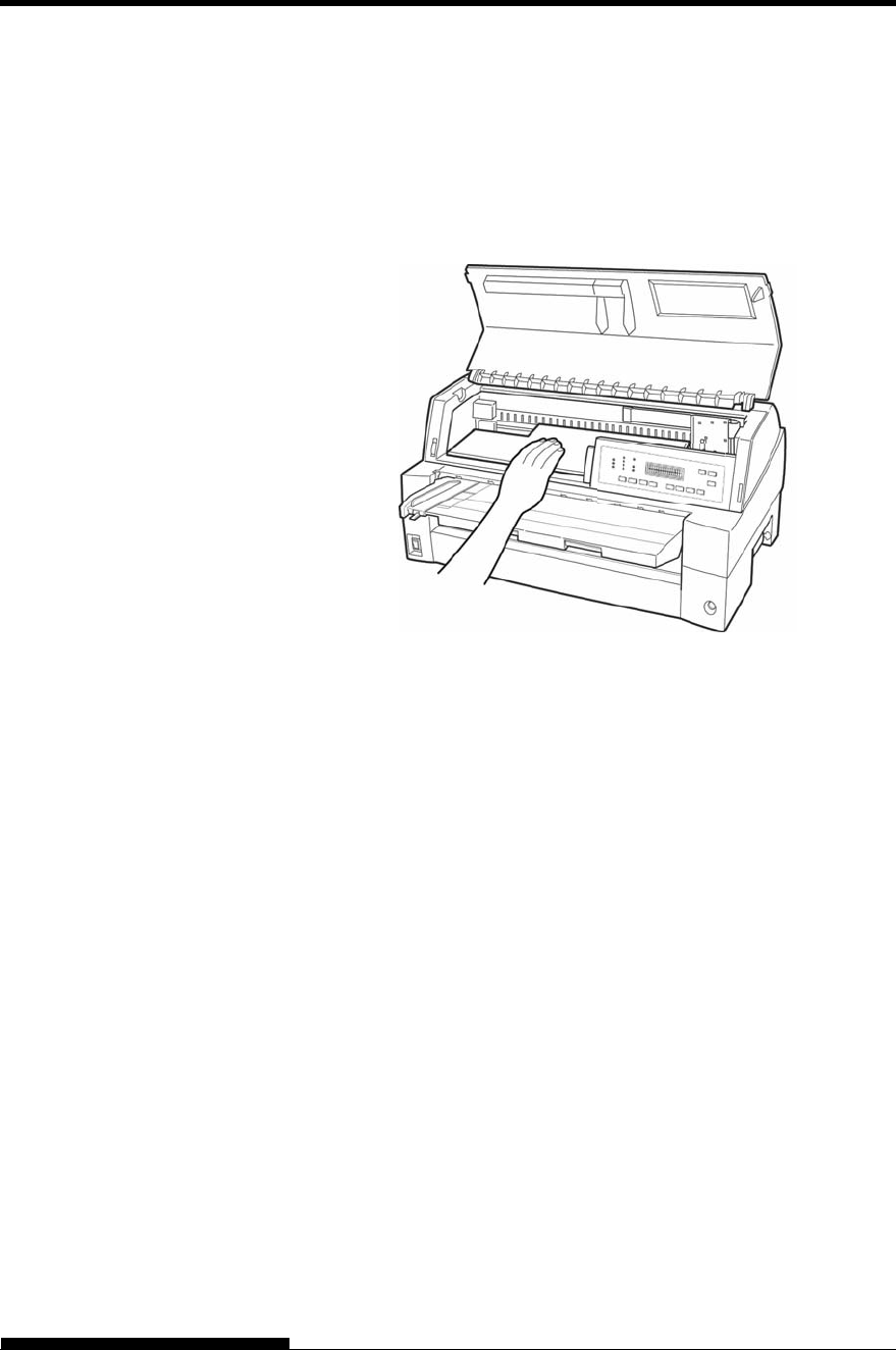
4. Remove the tapes and cushions securing the printer. Open the
front cover and remove the shipping restraint cardboard that
holds the print head carriage in place (shown below).
Removing the shipping restraint cardboard
5. Store the original shipping carton and packaging materials for
future use. For example, the original packaging is ideal for use
when you move or ship your printer to another location.
NOTE
The interface cable is not included with the printer. You must
purchase it separately. Connection of the interface cable is described
later in this chapter.

SETTING UP
2-4 User's Manual
Checking Options and Supplies
The following options and supplies, if ordered, are shipped separately:
LAN card (option)
Cut sheet feeder (option)
Tractor unit (option)
Small Paper Table (option)
Large Stacker (option)
Sound proof cover (option)
Extra monochrome ribbon cartridges
Make sure that you received all the options you ordered. Installation of
options is described in Chapter 8.
Once you are sure you have everything, you are ready to assemble the
printer.
SETTING UP
User's Manual 2-5
This section explains how to handle the paper table, change the tractor
unit position and install the ribbon cartridge.
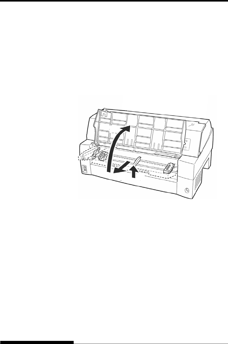
Handling the paper table
You must open or close the paper table when you operate the front
tractor.
1 Open the paper table.
Slightly raise the front end of the paper table (1), then pull (2) and
lift the table (3).
ASSEMBLING THE
PRINTER
(1)(2)
(3)
SETTING UP
2-6 User's Manual
2
Close the paper table.
Lower the paper table as shown in the figure below (1), then push
(2) and close (3) the cover.
The complete setup conditions are shown below. Make sure that the top
end of the paper table is engaged with the printer guide pin and the guide
pin on the paper table is inserted into the cover groove.
NOTE
Do not apply unreasonable force while you are handling the paper
table. It could cause damage. Also, do not leave the paper table in
incomplete setting. Running the printer with the paper table left in
incomplete conditions could cause a paper jam.
Cover groove. Paper table guide pin
Guide pin (metal stud)
(3)
(2)
(1)
SETTING UP
User's Manual 2-7
Installing the Ribbon cartridge
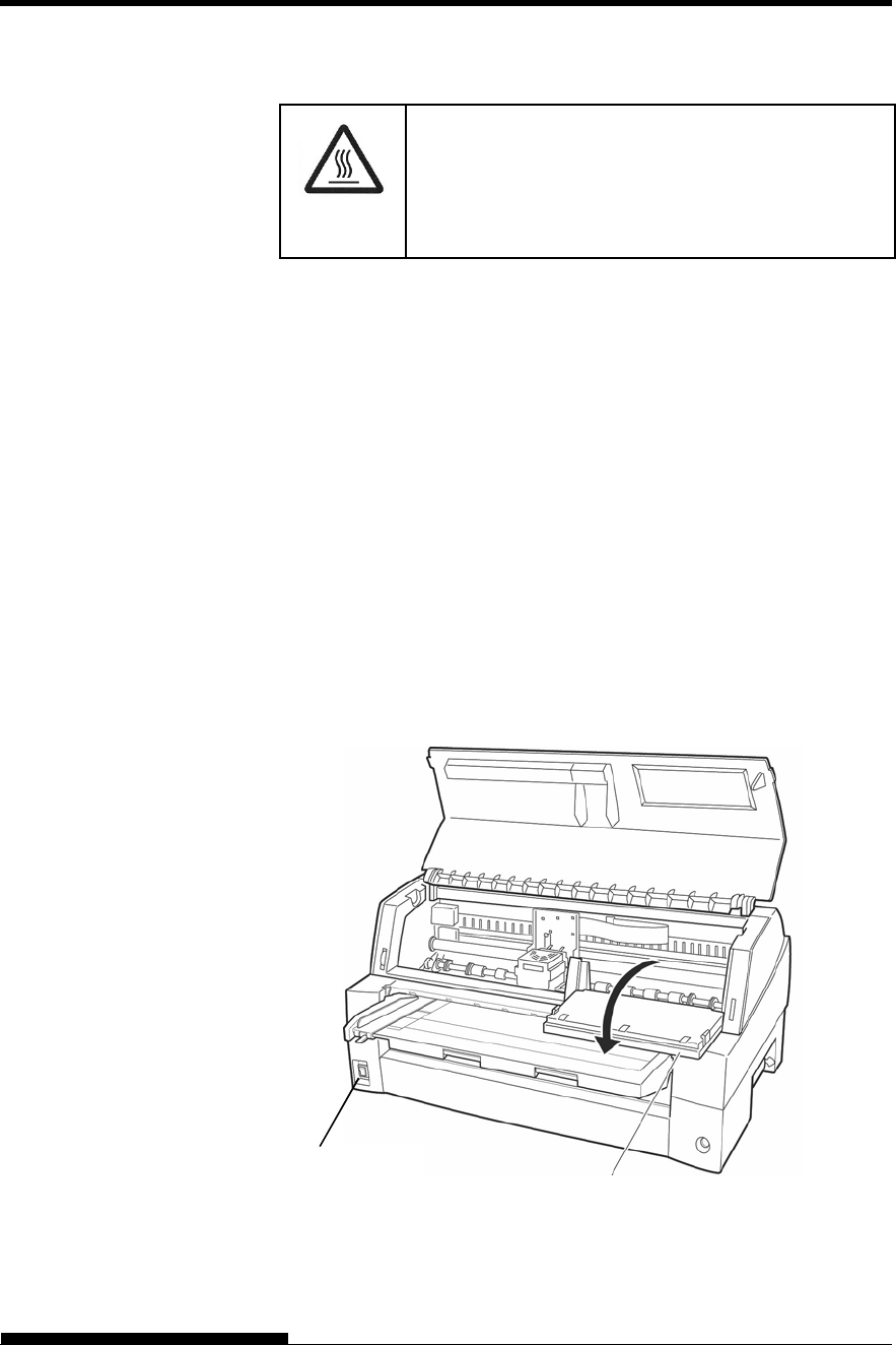
(HOT)
CAUTION <HOT>
The print head and metal frame is hot during
printing or immediately after printing. Do not touch
them until it cools down.
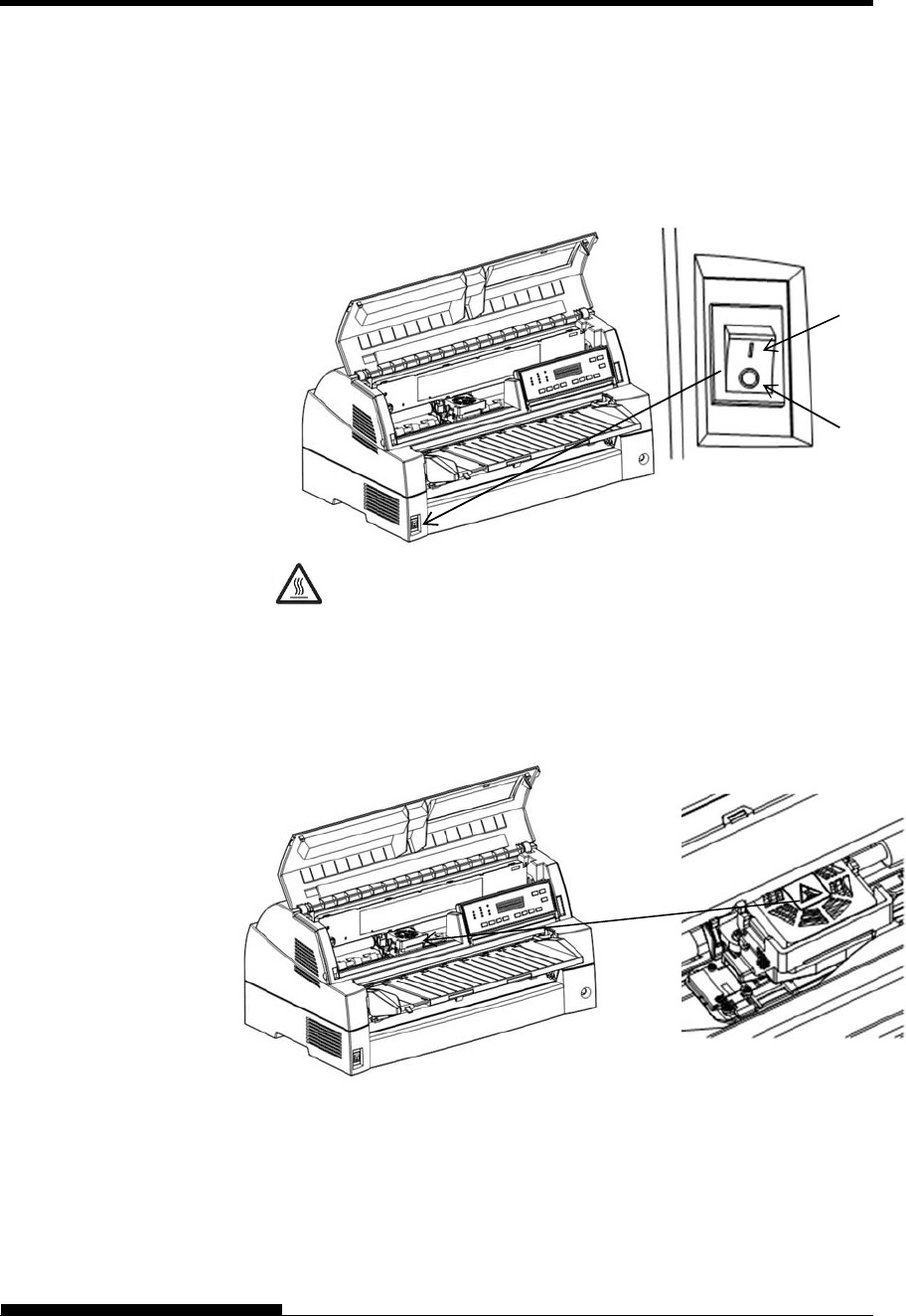
1. Prepare the printer to install the ribbon cartridge.
Make sure that the print head protecting cardboard used for
transportation has been removed, then turn on the printer power with
the top cover closed. Ensure that the print head moves and stops at
the ribbon replacement position.
NOTE
If you turn on the printer power with the top cover open, the
print head does not move. Turn the printer power with the
top cover closed.
2. Turn off the printer power.
Make sure that the power switch is set to the “” side.
3. Open the front cover of the printer. Slide the print head carriage so
that its center is at the position for replacing the ribbon cartridge
(indicated by the triangle marking on the front of the upper cover).
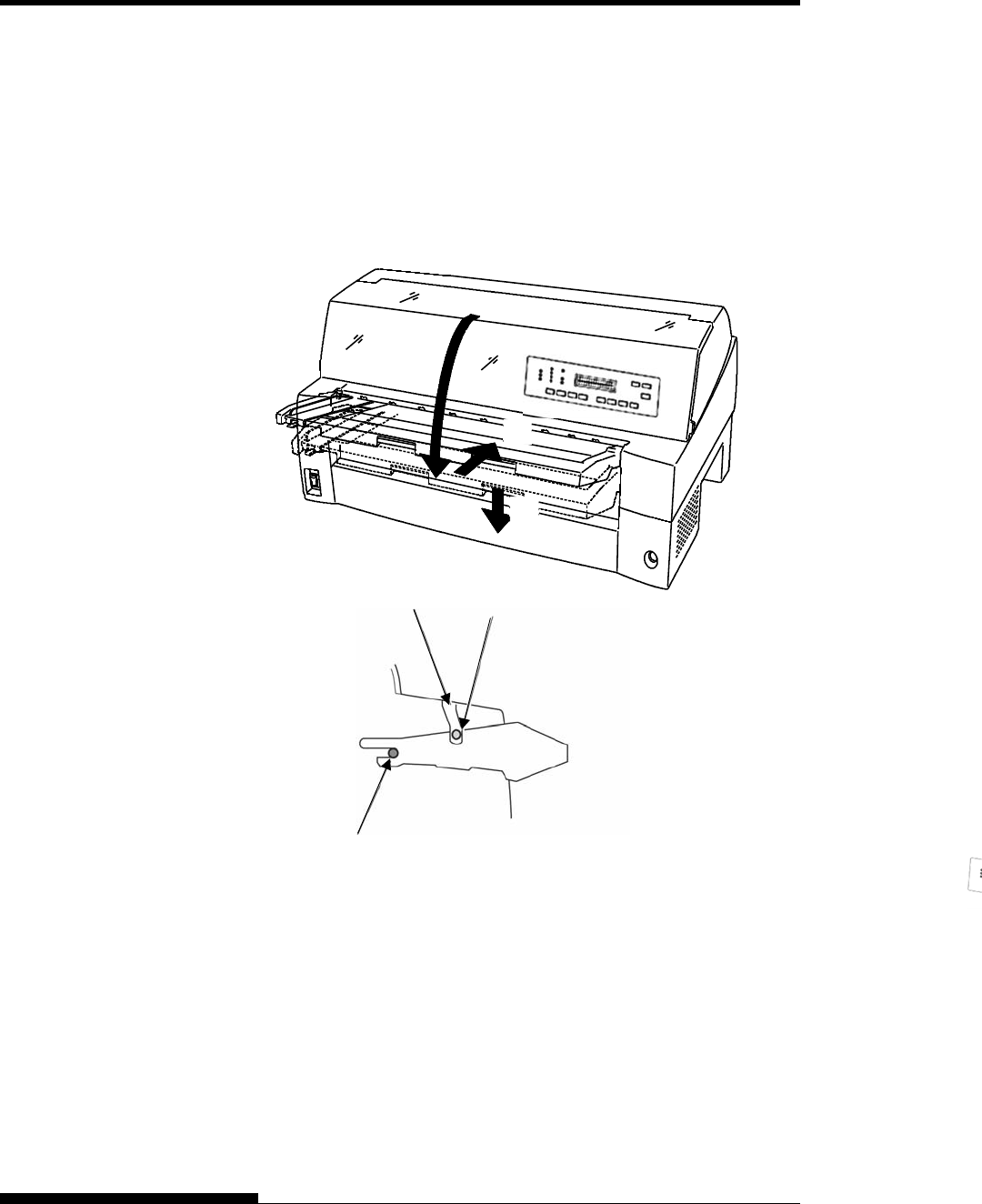
4. Open the control panel for easy installation of ribbon cassette.
Preparing the printer to install the ribbon cartridge
Power Switch
Control panel
SETTING UP
2-8 User's Manual
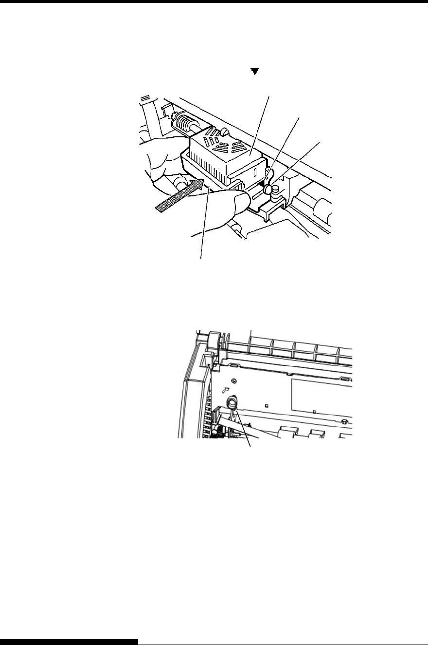
5. Remove the ribbon guide (green part) from the ribbon cassette.
Don’t turn the ribbon feed knob before installation.
Preparing the ribbon cassette
SETTING UP
User's Manual 2-9
5. Put the green ribbon guide into the space in front of print head. And
then place the mounting pins (both side of ribbon cassette) on the
slot of the printer cover. And then push the ribbon cassette so that
the ribbon cassette is installed vertically.
Installing the ribbon cassette
Mounting pi
n
Mounting pin
Ribbon guide
Print head Space Slot
Slot
Push the ribbon cassette until it
clicks.
SETTING UP
2-10 User's Manual
7. Attach the green ribbon guide on the print head.
Please make sure that the ribbon slack lightly. (If the ribbon is
strained, it will quirk when installation.)Push the green ribbon guide
until the triangle mark ” ”meets the round projection of print head.
8. Turn the ribbon feed knob clockwise to take up any slack in the
ribbon.
9. Return the control panel.
10. Close the front cover.
NOTE
A Fujitsu ribbon cassette is recommended. Don’t use other cassettes.
If other cassettes are used, operating problems or a damage of the
print head may be caused.
Triangle mark
Projections
Print Head
Ribbon Guide
Knob

SETTING UP
User's Manual 2-11
Selecting the Tractor Unit Position
NOTE
This printer uses a detachable tractor that can be used on either the
front or back of the printer. You can attach the tractor to either the
front or back of the printer according to your installation or
operating conditions. The printer is delivered to you with the tractor
attached to the front. You can detach it from the front and then
attach it to the back if needed.
See “SELECTING PAPER PATH” in Chapter 3.
SETTING UP
2-12 User's Manual
Mounting and removing the tractor unit
Tractor unit at the front
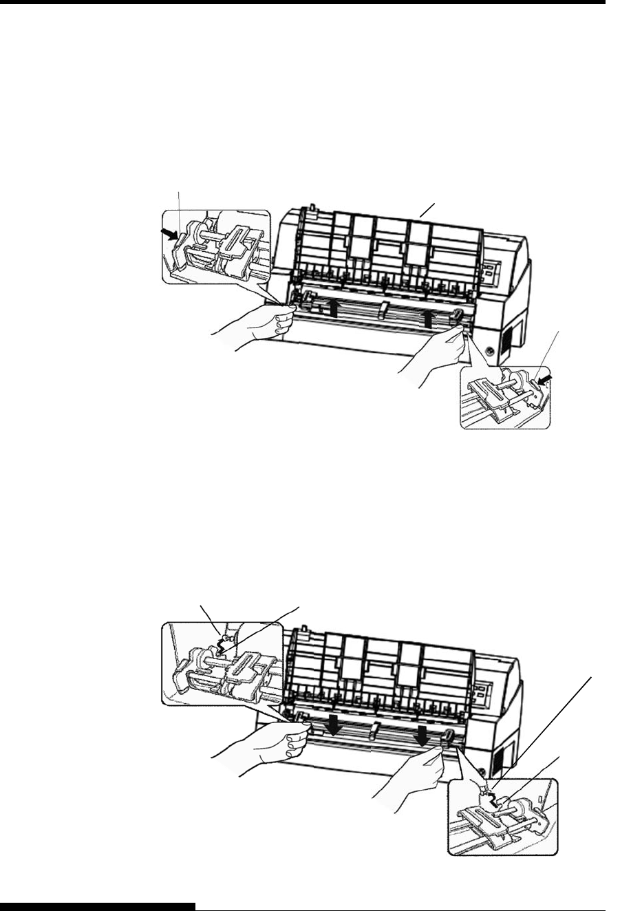
[Removing the tractor unit]
Raise the paper table. While pressing the lock levers of the tractor
frames located on both sides of the tractor unit, lift out the tractor
unit to remove it.
[Mounting the tractor unit]
1) Position the U-shaped slots on both sides of the tractor unit over the
guide pins of the printer unit. (To set the tractor unit in position, line
it up with the groove of the left guide pin. The right guide pin has
no groove).
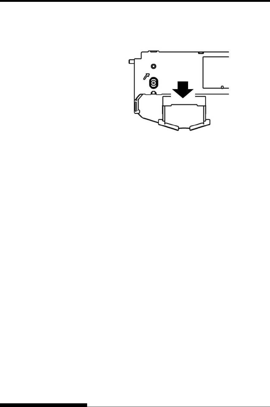
2) Push down the shaft at the front of the tractor unit until it locks with
an audible click. (Do not press the lock levers when pushing down
the shaft.)
Lock lever
Lock lever
Paper table
Guide pin
U-shaped slot
U-shaped slot
Guide pin
SETTING UP
User's Manual 2-13
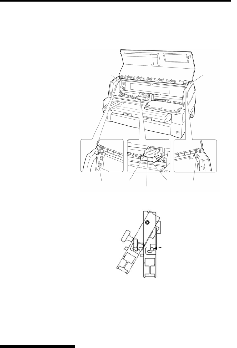
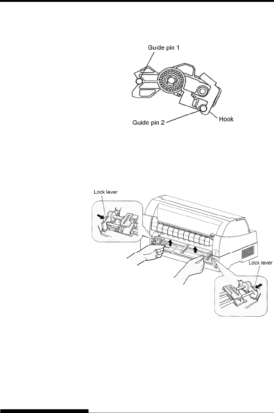
3) Verify that the hooks on both sides of the tractor unit are securely
hooked onto guide pin 2 as shown in the following figure.
Tractor unit at the rear
[Removing the tractor unit]
While pressing the lock levers of the tractor frames located on both
sides of the tractor unit, lift out the tractor unit to remove it.
SETTING UP
2-14 User's Manual
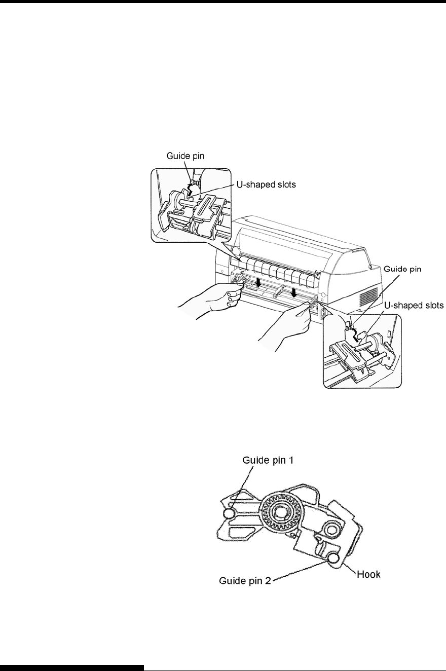
[Mounting the tractor unit]
1) Position the U-shaped slots on both sides of the tractor unit over
the guide pins of the printer unit. (To set the tractor unit in
position, line it up with the groove of the left guide pin. The
right guide pin has no groove).
2) Push down the shaft at the front of the tractor unit until it locks
with an audible click. (Do not press the lock levers when
pushing down the shaft.)
3) Verify that the hooks on both sides of the tractor unit are
securely hooked onto guide pin 2 as shown in the following
figure.
SETTING UP
User's Manual 2-15
Now that your printer is assembled, take a moment to become familiar
with its major parts.
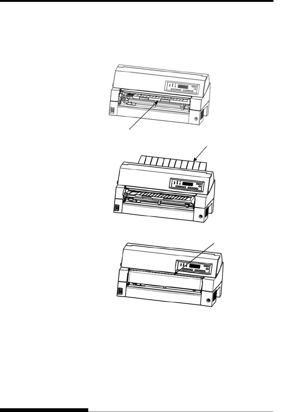
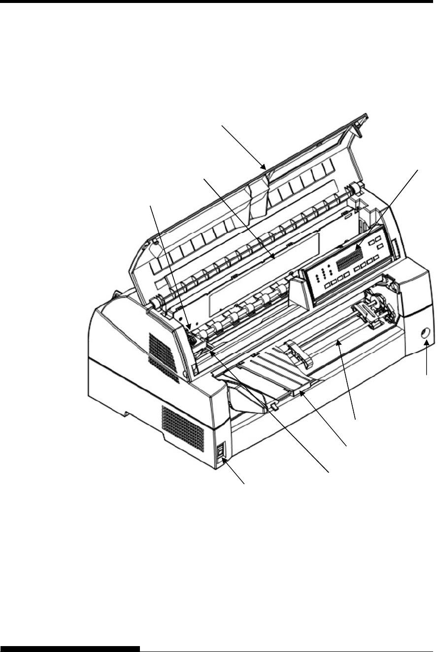
Looking at the printer from the front left side and rear right side, you can
see the parts of the printer shown in the figure below.
Printer components (front)
The printer control panel has the buttons and indicators used to load and
feed paper (see Chapter 3) and select print features (see Chapter 4). The
control panel also allows you to change the printer’s optional settings
(see Chapter 5).
GETTING
ACQUAINTED WITH
YOUR PRINTER
Paper table
Tractor unit
Front cover
Ribbon cassette Control Panel
Power Switch
Front CSF connector
Print Head
Card Guid
e
(Aluminum print guide)
SETTING UP
2-16 User's Manual
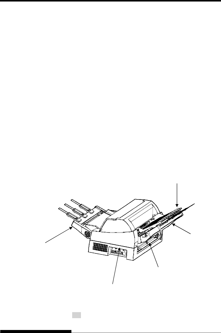
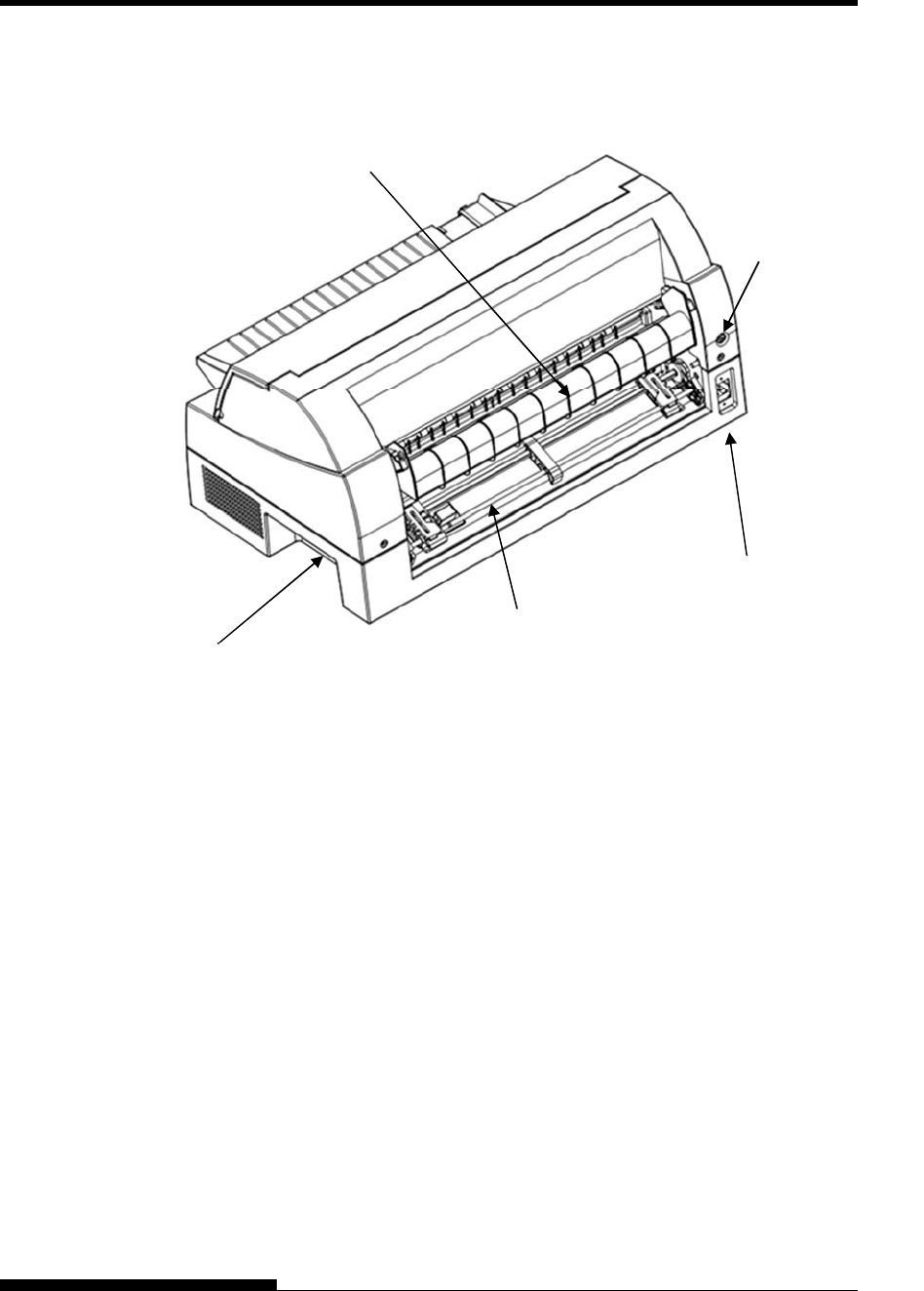
Printer components (rear)
Tractor unit (option).
Power Connector
Rear stacker
Rear CSF connector
INF connector
SETTING UP
User's Manual 2-17
The explanation of Symbols on the printer
• Power Switch
Turns the printer power ON (Printable Condition)/ OFF (Unprintable
Condition).
Print head
The print head become extremely hot during printer operation and
remain so immediately afterwards. Do not touch these parts until
sufficient time has passed to allow them to cool.
Otherwise, burns or personal injury may result.
ON
OFF
SETTING UP
2-18 User's Manual
Before you plug in the printer:
Make sure that the printer power is switched off. The side
marked “” on the power switch should be depressed.
Make sure that the power outlet is properly grounded.
Make sure that you use the power cord shipped with the printer.
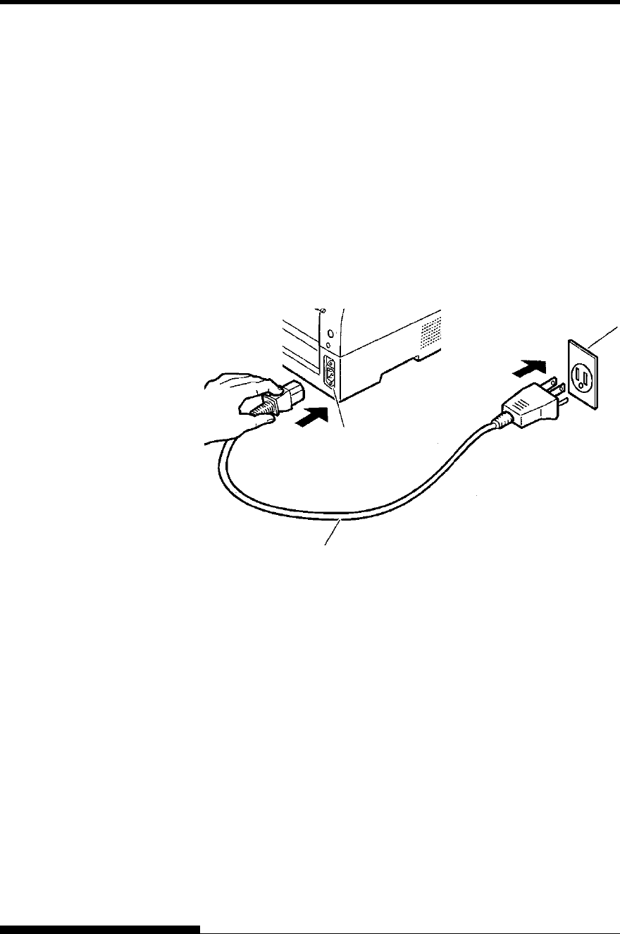
To plug in the power cord:
1. Plug one end of the power cord into the power connector on the
rear of the printer.
2. Plug the other end of the power cord into the power outlet.
Connecting the power cord
3. Make sure that the power cord is securely connected.
4. Turn on the power by pressing the side marked “I” on the power
switch. The POWER indicator on the printer control panel will
light, the print head will move to its home position within a few
seconds, and the ONLINE indicator will light (green).
NOTE
If no forms are loaded, the printer beeps and the PAPER OUT
indicator lights and the ONLINE indicator will not light.
CONNECTING THE
POWER CORD
Power connector
Power cord
Power outlet
SETTING UP
User's Manual 2-19
At this point, load paper and run the printer self-test. The self-test checks
printer performance and print quality before you connect the printer to
the computer.
Loading Paper for the Self-Test
To print the self-test, load continuous form wider than 254 mm (10
inches) and set the left tractor so that the left end of continuous form
may suit “0-10mm” of a scale (see Chapter 3).
Printing the Self-Test
The printer has a built-in self-test program. The self-test prints the
firmware version, the names of the printer’s resident emulations, and all
of the characters available in the emulations. The self-test prints 80
characters per line.
To print a self-test page, make sure that continuous forms are loaded.
Then proceed as follows:
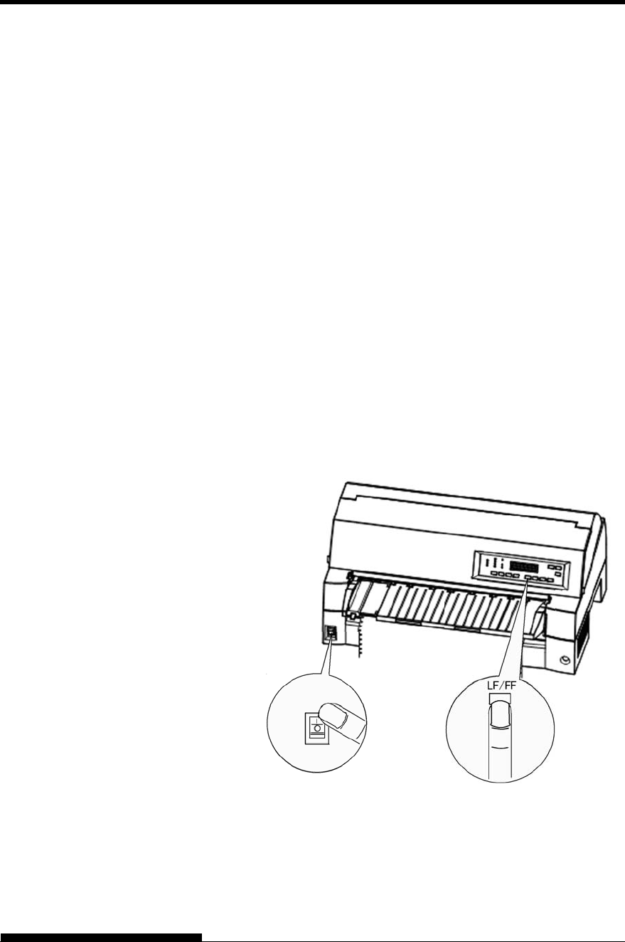
1. Turn the printer off.
2. While pressing the LF/FF button, turn the printer back on.
Keep the LF/FF button pressed until the printer beeps.
Self-test printing will start.
Starting the self-test
3. Allow printing to continue for a dozen or more lines of repeat
printing. To exit the self-test mode, press the ONLINE button.
To remove the test page refer to Chapter 3.
TESTING THE
PRINTER (OFFLINE)
SETTING UP
2-20 User's Manual
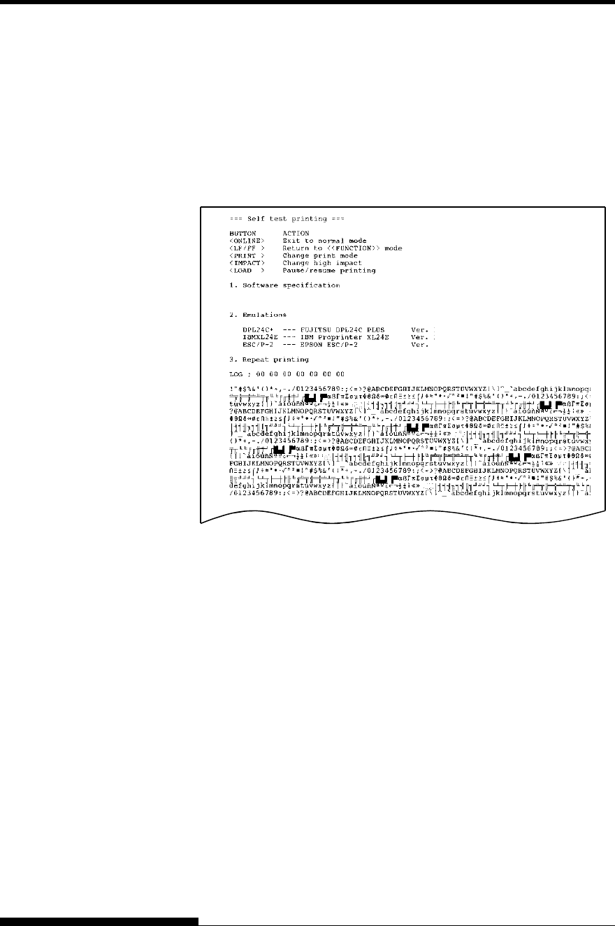
4. Examine the self-test page. It should look like the sample on the
below.
Check that printing is uniform and that there are no light, dark,
or smudged areas. If the print quality is good, go to step 5.
Otherwise, try to correct the problem as follows:
Make sure that the ribbon is installed correctly.
Load a new sheet of paper.
Repeat the self-test procedure.
Sample self-test page
5. To exit the self-test mode, press the ONLINE button. The
printer will return online.
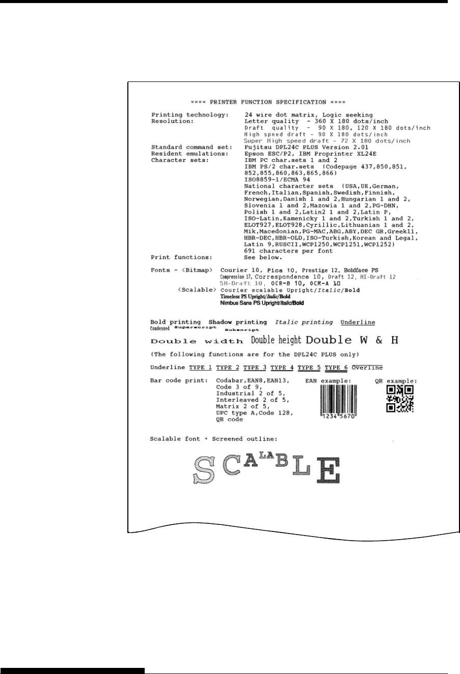
NOTE
The printer can also print a special “demo pattern” that illustrates
some of the printer’s capabilities. To print the demo pattern:
1. Load continuous forms (wider than 254 mm (10 inches)).
2. Turn the printer off .
3. While pressing the PRINT MODE button, turn the printer back
on.
The printer will start printing the demo pattern.
4. The demo pattern stops printing after one page. To pause or
restart the demo during printing of a page, press the ONLINE
button.
5. To exit demo mode, turn the printer off.
XXXXX-XXXX(XXX) XXXXX
X.XX
X.XX
X.XX
SETTING UP
User's Manual 2-21
Demo pattern

SETTING UP
2-22 User's Manual
Your printer supports one of the following interface options:
Centronics parallel interface+RS-232C serial interface
Centronics parallel interface+USB (+LAN) interface
The parallel interface connector has wire clips. The serial interface
connector has tapped holes. Cables for these interfaces are available from
dealers, cable manufacturers, and other suppliers.
The LAN card is a user installable option. For details, see Chapter 8.
For detailed interface specifications, see Appendix D.
Selecting a Parallel Interface Cable
For the parallel interface, use a cable that meets the following
specifications:
At the printer end, use a shielded male Centronics connector,
such as an Amphenol DDK 57FE-30360 or its equivalent. To
prevent RFI (radio frequency interference), the connector cover
must be connected to the cable shield.
Make sure that the cable length does not exceed 3 meters (10
feet).
Selecting a Serial Interface Cable
For the serial interface, use a cable that meets the following
specifications:
At the printer end, use a 25-pin male connector, such as a
Cannon DB-25P or its equivalent.
To determine the type of connector your computer requires,
refer to your computer user manual or ask your dealer.
The cable length can be up to 15 meters (50 feet). This type of
length is required in many networking and shared-printer
configurations.
CONNECTING THE
PRINTER TO YOUR
COMPUTER
SETTING UP
User's Manual 2-23
Selecting a USB Cable
When the USB interface is used to connect to the host computer,
the parallel interface and the serial interface (factory add-on
option) cannot be connected simultaneously.
The USB interface does not guarantee all connections of USB-
supported devices.
Selecting a LAN cable
When the LAN cable is connected, the parallel and USB cables
cannot be used.
The LAN cable, when used in 100BASE-TX environments,
must conform to category 5 or higher.
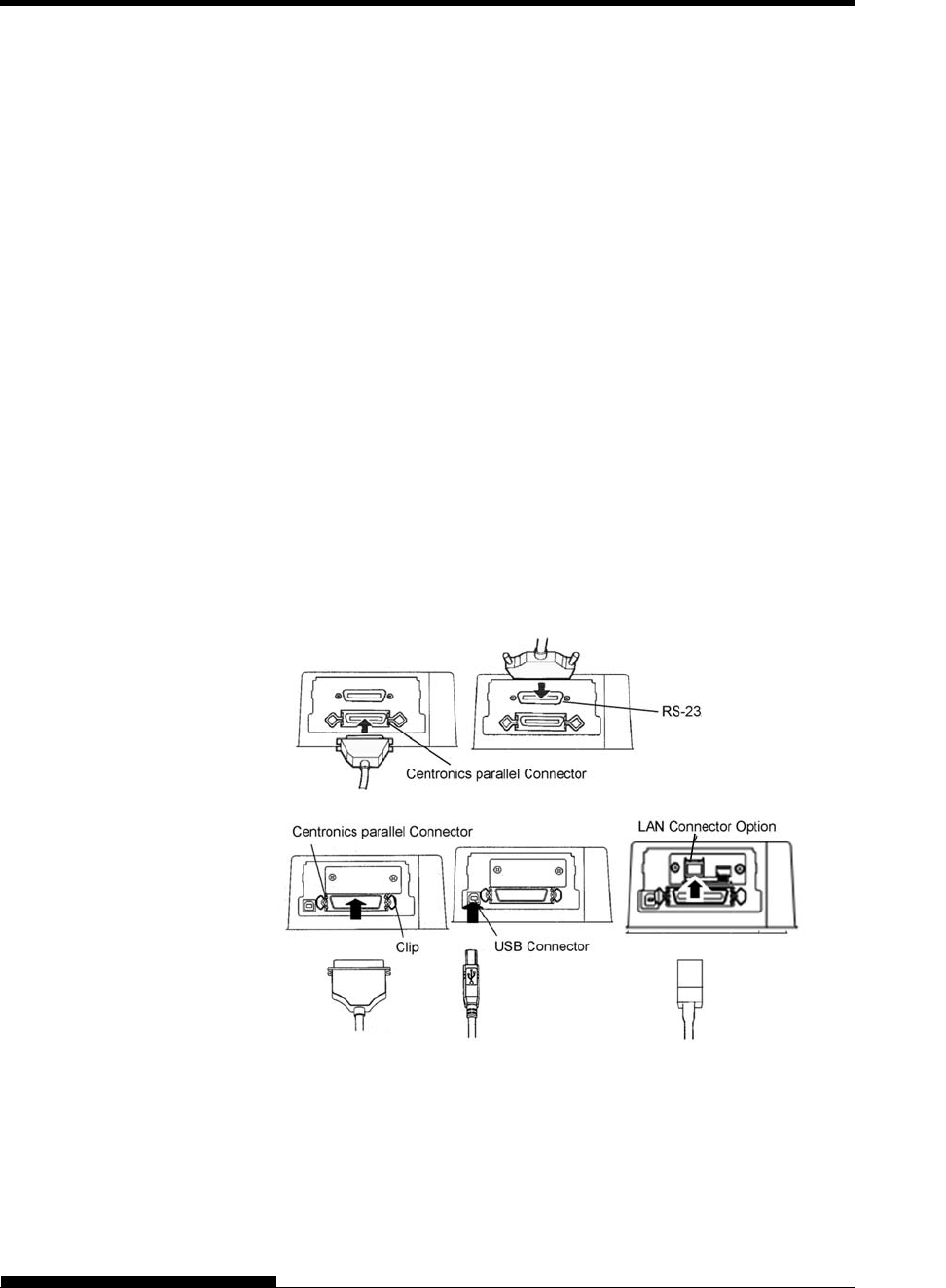
Connecting the Interface Cable
To connect the interface cable:
1. Turn off both the printer and the computer.
2. Attach the interface cable to the connector. Do not connect more
than one interface cable type to the printer at the same time.
Connecting the interface cable
RS232C Serial connector

SETTING UP
2-24 User's Manual
NOTE
The LAN interface is a user add-on option.
When installing a LAN card, remove the two screws securing the
cover and remove the cover. Then insert the LAN card and reattach
the cover with the two screws removed earlier. For details, see
Chapter 8.
3. To secure a parallel interface cable, flip the fastener clips
located on the printer into the notches on the cable connector.
To secure a serial interface cable, tighten the screws in the cable
connector.
4. Attach the other end of the interface cable to your computer.
Gently pull on the cable to verify that it is secure.
Before printing with your software, verify that the correct emulation
is selected on your printer. This section describes the available
emulations and their selection.
For Experienced Users:
The printer’s factory default factory setting is the Fujitsu DPL24C PLUS
emulation. If this emulation is acceptable, you may skip this section.
An emulation is a set of commands used by your software to
communicate with the printer. There are different emulations available
for printers.
Each emulation has unique features and capabilities. This printer offers
three resident emulations:
Fujitsu DPL24C PLUS (for Fujitsu DL-series printers)
IBM Proprinter XL24E
Epson ESC/P2
Resident emulations are stored in the printer’s permanent memory.
Here are some points to help you determine which emulation to select:
Determine which emulations your software supports. (Refer to
your software documentation.) Since most software programs
support this printer, try to run a program with the factory default
emulation first.
(DPL24C PLUS emulation is the factory default.) Try this
emulation even if you are not sure of which emulation to choose.
See Chapter 5 for detailed information about how your printer
communicates with your software.
SELECTING AN
EMULATION
SETTING UP
User's Manual 2-25
If you are using more than one software package, determine
which emulation is supported by the software you use most
frequently.
Select that emulation.
If your software supports more than one emulation, select the
DPL24C PLUS emulation if possible. This emulation has the
greatest capabilities.
If you want to use an emulation that is not supported by your
software, contact your software manufacturer or printer dealer
and ask whether support is available. You may be able to obtain
a printer driver that is not shipped with the original software
package.
To select an emulation, proceed as follows(LED):
1. Turn the printer on and load continues forms.
To print the “OFFLINE SET UP MODE”, load continuous form
wider than 254 mm (10 inches) and set the left tractor so that the
left end of continuous form may suit “0-10mm” of a scale (see
Chapter 3).
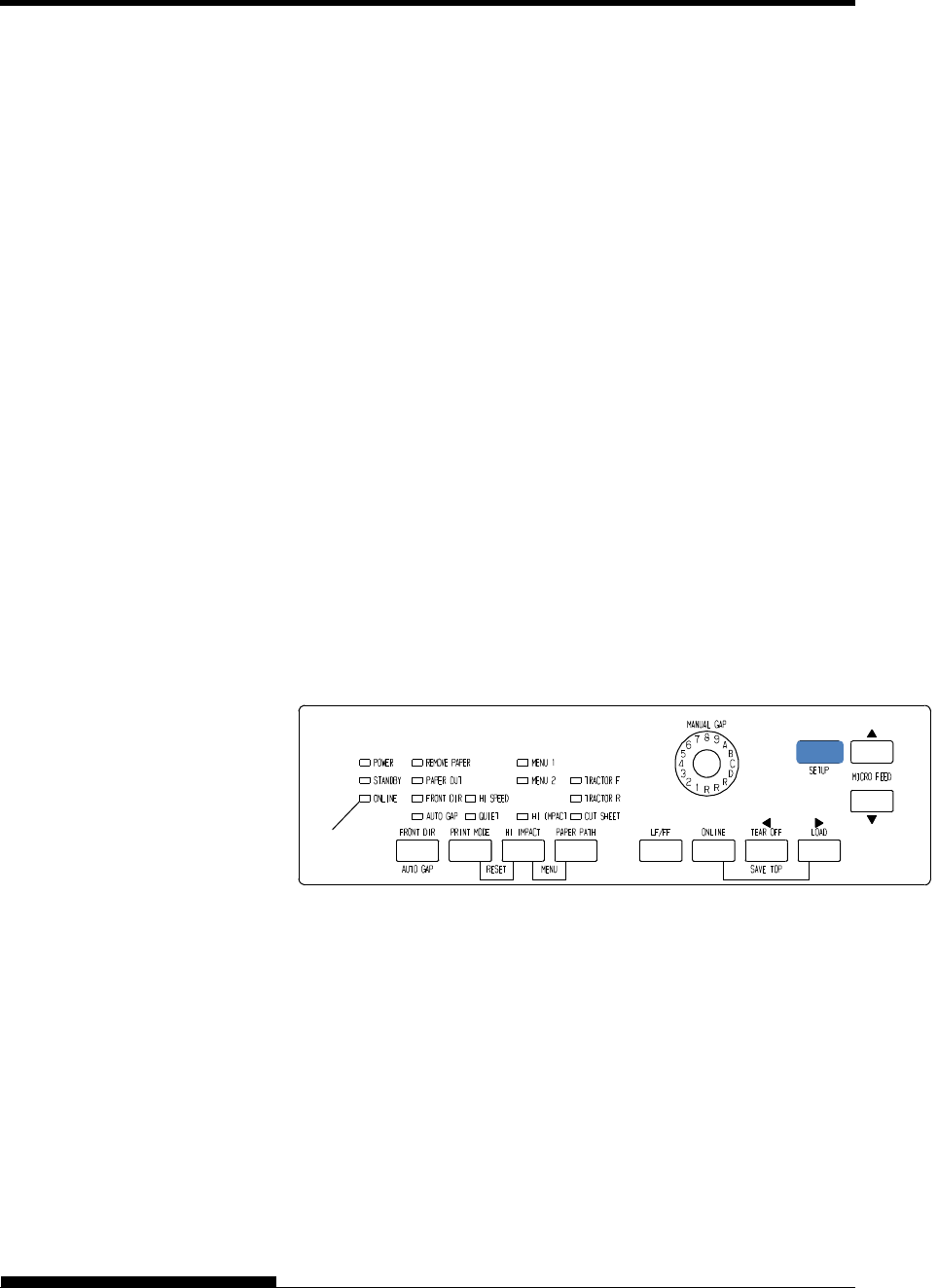
2. Enter setup mode.(LED)
Press the ONLINE button to place the printer offline. Then,
press the SETUP button.
As the printer enters offline setup mode, it prints the following
information:
NOTE
If LCD type control panel. Please refer to Chapter 5.
OFF
SETTING UP
2-26 User's Manual
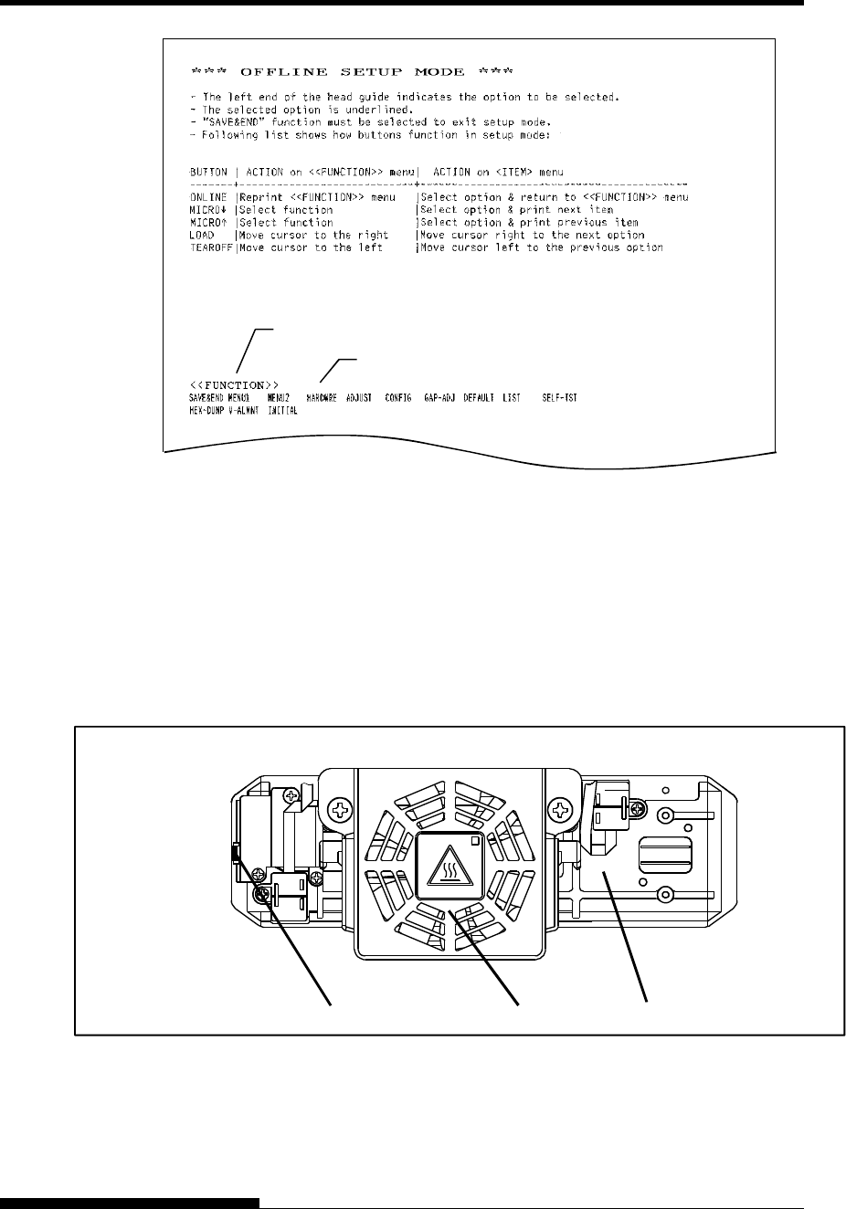
Initial printout in setup mode
Check that the <<FUNCTION>> menu is printed at the bottom
of the page.
3. Select the MENU1 function.(LED)
Locate the cursor on left edge of the Card guide (aluminum
print guide). Initially, this cursor should be positioned at SAVE
& END at the beginning of the <<FUNCTION>> menu. Press
the LOAD button repeatedly to position the cursor at MENU1,
as shown below:
<<FUNCTION>> menu
Function
Cursor Card guide Print head
<<FUNCTION>>
SAVE&END MENU1
HEX-DUMP V-ALMNT
SELF-TEST

SETTING UP
User's Manual 2-27
Press the MICRO FEED button to select MENU1 and print
the following <EMULATE> options:
<EMULATE> DPL24C+ XL24E ESC/P2
The currently selected emulation is indicated by a short
underline. In the figure shown above, the Fujitsu DPL24C
PLUS emulation is selected.
4. Select an emulation.(LED)
Press the LOAD button repeatedly to position the cursor at the
required emulation. Press the MICRO FEED button to select
the emulation and print the next MENU1 item.
5. Exit MENU1.(LED)
Press the ONLINE button to exit the MENU1 function and
reprint the <<FUNCTION>> menu.
6. Exit setup mode to save the emulation.(LED)
To exit setup mode and save the new emulation, make sure that
the cursor is positioned under SAVE & END. Then press the
MICRO FEED button. The printer selects SAVE & END
and then goes online.
To change other printer settings using the printer setup mode, see
Chapter 5.
Once the self-test verifies that the printer is functioning correctly, try
printing using one of your software packages. This exercise will ensure
that the printer is correctly connected to your computer.
If you are using a parallel interface, the printer usually prints the correct
characters automatically. However, you may need to adjust the page
layout or various print features using your software or the printer setup
mode. If you are using a serial interface, the printer may not work at all
or it may print a lot of “?” characters. In this case, the serial settings on
the printer do not match those of your computer or your software. Before
changing any settings, use the procedure described below to try printing
using the printer’s preselected factory settings.
Test communication between the printer and computer as follows:
1. Load continuous forms.
2. Check that the printer is online. If the ONLINE indicator is not
green, press the ONLINE button.
3. Try to print using your word processor, a programming
language, or other software.
PRINTING A
SAMPLE PAGE
(ONLINE)

SETTING UP
2-28 User's Manual
4. Use your software printer selection menus or the printer setup
mode (described in Chapter 5) to make required changes in the
page layout or other print features.
If the printer does not print or prints the wrong characters,
proceed as follows:
Make sure that the interface cable is properly connected.
Make sure that the printer emulation selected in your
software is the same as that selected on the printer.
If you are using a serial interface, make sure that the printer
serial interface settings are the same as those on the
computer. The printer’s factory default settings are 8 data
bits, no parity, 1 stop bit, 9600 baud, and XON/XOFF
protocol.
You can change the serial settings on either the printer or
your computer. To change the printer settings, see Chapter
5. To change the computer settings, use the selection menus
provided by your software or the commands of your
computer operating system.
The following example uses the MS-DOS operating
system:

SETTING UP
User's Manual 2-29
Using MS-DOS to Specify Serial Interface Settings
For an IBM PC or compatible device, use the following MS-DOS
MODE commands to set the computer serial settings to match the
printer factory default settings:
MODE COM1:9600,N,8,1,P
MODE LPT1:=COM1
To activate these settings whenever you turn the computer on, write the
MODE commands in your AUTOEXEC.BAT file. Make sure that the
MODE.COM file is included in your root directory.
If the printer still doesn’t work, consult your dealer or
someone experienced in serial interface communications.
If an error occurs during printing with Windows, simply
printing the page again will cause the printed characters to
be garbled. To avoid this problem, execute reset from the
control panel or turn off the printer, then print the page
again.
You are now finished setting up and testing the printer. To familiarize
yourself with everyday printer operations, such as loading paper,
selecting print features, and printing, see Chapters 3 and 4.
A printer driver is required for using the printer in a Windows
environment. Special printer drivers are provided with the DL7600Pro
printer.
For information about how to install printer drivers, refer to
INSTALLGUIDE_(LANG).PDF or Readme.txt of the printer driver to
be installed.
- These printer drivers run with DLP24C+ emulation. Be sure to
specify DLP24C+ emulation for the printer mode.
- The DL7600Pro printer driver is a printer driver for
monochrome printing.
The color data printing result may differ from its print preview
or the monochrome data printing result.
INSTALLING THE
PRINTER DRIVER
User's Manual 3-1
3
CHAPTER 3 PAPER HANDLING
PAPER HANDLING
This chapter explains how your printer uses paper.
Topics covered are:
Selecting paper
Overview of paper operations
Selecting the paper path
Adjusting for paper thickness
Using continuous forms (front-tractor feed and rear-tractor feed)
Using single sheets
Feeding and positioning paper
Switching paper types
Tips for paper handling are given at the end of this chapter. Check that
section if you are using multipart forms, envelopes, or labels.
The printer can handle either single sheets or continuous forms. Single
sheets, also called cut sheets, include envelopes and non-continuous,
multipart forms. Continuous forms include labels and multipart forms fed
into the printer using the forms tractors.
For best results, use paper that meets the specifications listed below.
(See Appendix B for detailed specifications.) If you are unsure of the
suitability of a particular paper, try testing the paper or consult your
dealer.
Length Single sheets: 70 to 420 mm (3 to 16.5 in)
Continuous forms: 102 mm (4 in) or greater
Width Single sheets: 55 to 420 mm (2.16 to 16.5 in)
Continuous forms: 102 to 420 mm (4 to 16.5 in)
Thickness 0.65 mm (0.026 in) maximum total thickness.
Copies 1 to 9-copies (Paper table/Front/Rear tractor)
1 to 5-copies (Cut sheet feeder)
Note:
To use cut sheets exceeding 297 mm in length, the optional large
stacker are required.
SELECTING PAPER
PAPER HANDLING
3-2 User's Manual
The following buttons are used in paper handling:
LF/FF, TEAR OFF, PAPER PATH, MICRO FEED,
MICRO FEED and LOAD buttons on the control panel
(Different functions are enabled when each button is pressed in
conjunction with the ONLINE button.)
The following figure shows the location of each button:
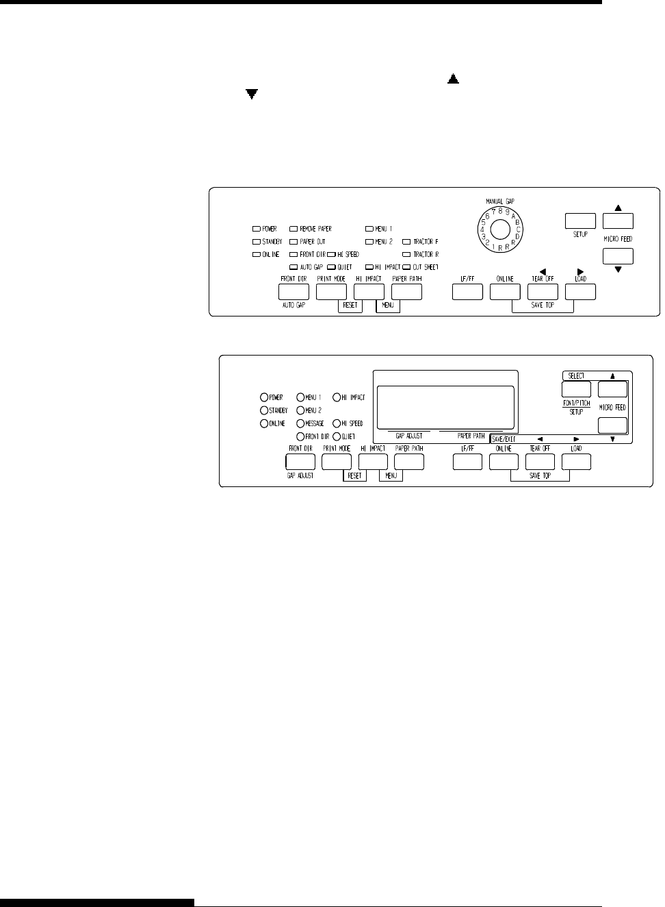
LED type Control panel
LCD type Control panel
Location of the buttons
Table 3.1 summarizes the use of buttons in paper handling. More detailed
information is provided later in this chapter.
NOTE
To load or feed paper, the printer must be:
Online but not receiving or printing data
Offline but not in setup mode
To micro feed paper, the printer must be:
Online but not receiving or printing data
Offline but not in setup mode
OVERVIEW OF
PAPER
OPERATIONS
PAPER HANDLING
User's Manual 3-3
Table 3.1 Buttons Used for Paper Handling
Button/Dial Purpose Action
ONLINE Change the
printer mode
Stop/resume
printing
Press ONLINE to place the printer online or offline.
Press ONLINE to stop or resume printing.
LOAD Load/unload
paper
Save adjusted
load point
Press LOAD to load paper or to retract continuous
forms to the “park position.”
Press LOAD and ONLINE simultaneously to
permanently store a load position adjusted by micro
feeding immediately after loading paper.
LF/FF Form feed
Line feed
Press and hold LF/FF to execute a form feed.
Continuous forms are fed forward by one page.
Single sheets are ejected.
Press LF/FF within three seconds to feed paper
forward by one line.
TEAR OFF Advance
forms for
tear-off
Press TEAR OFF to advance the forms perforation
to the tear-off edge. Tear off the forms, then press
any button to retract the remaining forms.
PAPER
PATH
Selects paper
path
Press PAPER PATH to select the paper path: front
tractor, rear tractor, cut sheet.
PAPER HANDLING
3-4 User's Manual
Table 3.1 Buttons Used for Paper Handling (Cont.)
Button/Dial Purpose Action
(LED)
FRONT
DIR/AUTO
GAP
(LCD)
FRONT
DIR/GAP
ADJUST
Select cut
sheet ejection
(LED)
Press FRONT DIR/AUTO GAP at Offline to select
a direction of ejecting cut sheet.
(LCD)
Press FRONT DIR/ GAP ADJUST at Offline to
select a direction of ejecting cut sheet.
Front ejection – FRONT indicator lights. It blinks
when paper is ejected to the paper table prompting
the user to remove the paper.
Rear ejection – FRONT indicator does not
light.
When you save your setting in the setup mode, it
becomes the new default. The default setting is
invoked whenever you turn on the printer.
MICRO Micro Feed Press MICRO/ MICRO to feed paper by 1/180
inch in the direction of the arrow.
MICRO
(LED)
AUTO GAP
Select paper
thickness
control mode
Select paper thickness control mode.
AUTO GAP — AUTO GAP indicator lights.
Manual Gap — AUTO GAP indicator doesn't
lights.
The Manual Gap dial is enabled.
(LED)
MANUAL
GAP DIAL
Select paper
Thickness at
MANUAL
MODE
Select the paper thickness at MANUAL MODE.
Auto Gap is usually used. Auto Gap is used for
printing on paper of different thicknesses.
(LCD)
GAP
ADJUST
Select paper
Thickness
Select the paper thickness as follows.
AUTO,GAP-1,・・・・・・・,GAP-9,GAP-A,・・,GAP-D
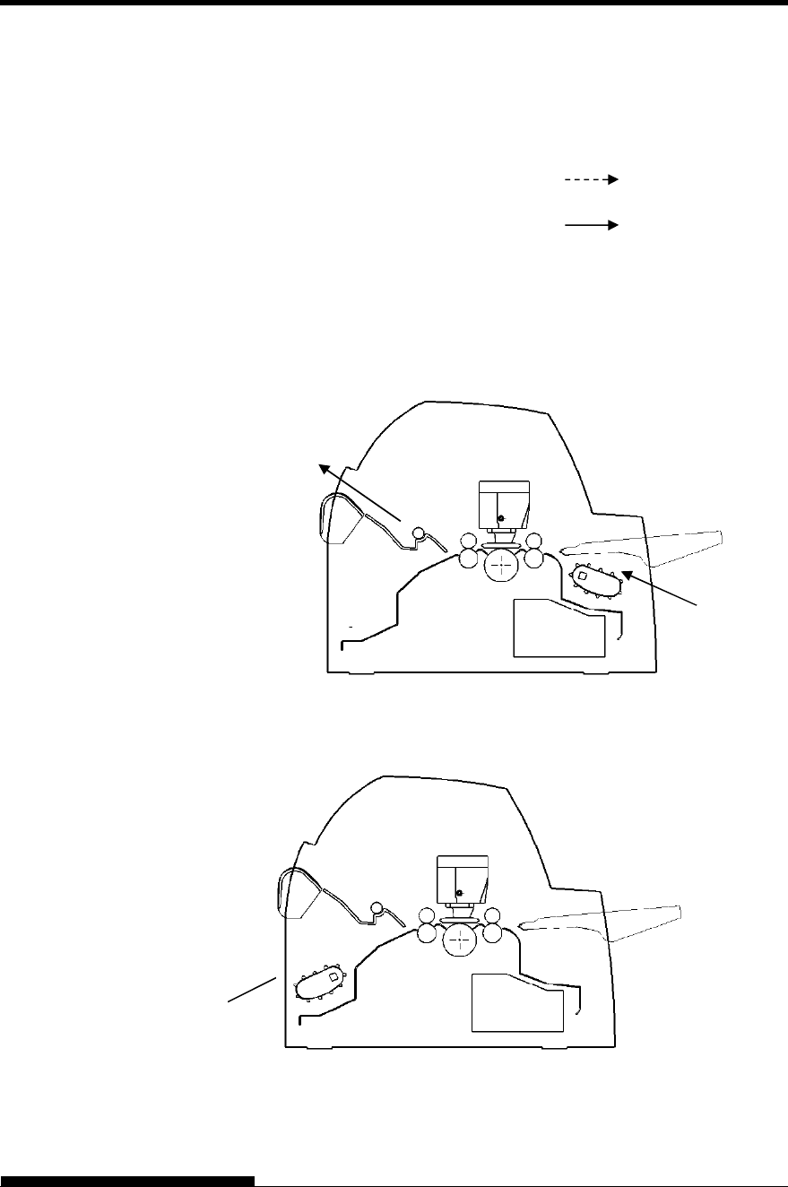
PAPER HANDLING
User's Manual 3-5
This printer has a variety of paper paths and feed directions.
Paper Paths and Feed Directions
See the following five cases. : Cut sheet
: Continuous forms
(n) : Input
[n] : Output
With front tractor
(1) Front tractor Print Rear eject
With rear tractor
(2) Rear tractor Print Front eject
SELECTING PAPER
PATH
(1)
[1]
(2)
[2]
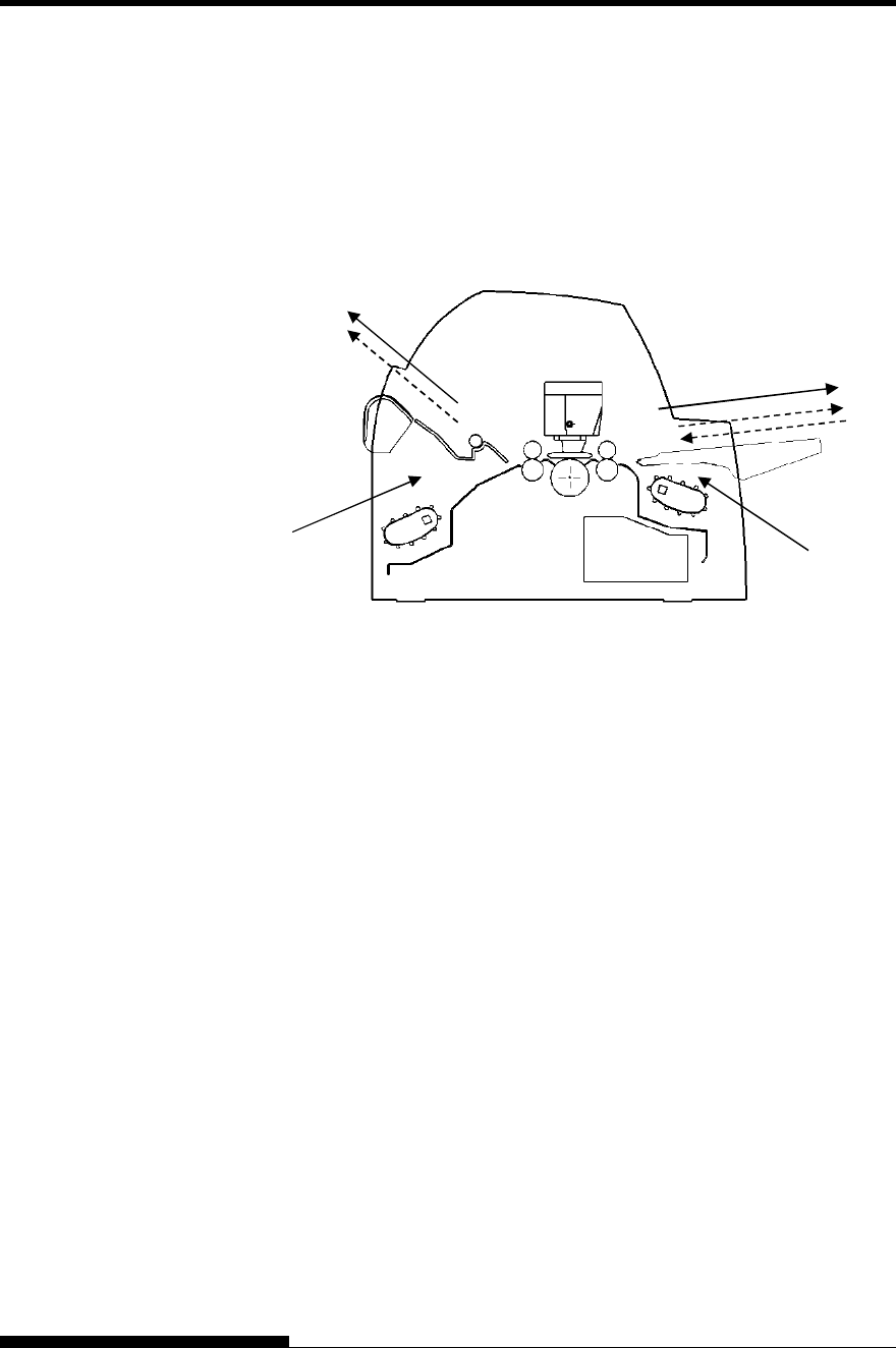
PAPER HANDLING
3-6 User's Manual
With front and rear tractors (either optional)
(1) Front tractor Print Rear eject
(2) Rear tractor Print Front eject
(3) Paper table Print Paper table
(4) Paper table Print Rear stacker
(1)
(2)
[2]
[1]
[3]
(3)(4)
[4]
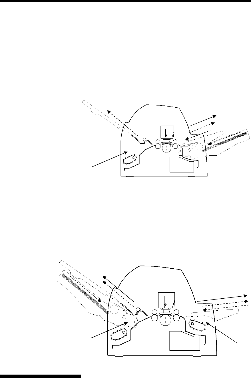
PAPER HANDLING
User's Manual 3-7
In the next two cases, the number of cut sheets stacked in the printer may
be reduced depending on printing conditions and environments. Follow
the notes.
With rear tractor and front optional cut sheet feeder and
large stacker(optional) .
(2) Rear tractor Print Front eject
(3) Paper table Print Paper table
(4) Paper table Print Rear stacker
(5) Front cut sheet feeder Print Paper table
(6) Front cut sheet feeder Print Rear stacker
With front or rear tractor (either optional)and rear optional cut
sheet feeder and large stacker(optional).
In addition, the front and rear tractor (either is optional) can be mounted.
(1) Front tractor Print Rear eject
(2) Rear tractor Print Front eject
(3) Paper table Print Paper table
(4) Paper table Print Rear stacker
(7) Rear cut sheet feeder Print Paper table
(8) Rear cut sheet feeder Print Rear stacker
(5)(6)
(2)
[2]
[
3
]
[
5
]
(3)(4)
[4] [6]
(1)
(2)
[2]
[1]
[3][7]
(3)(4)
[4]
(7)(8)
[8]
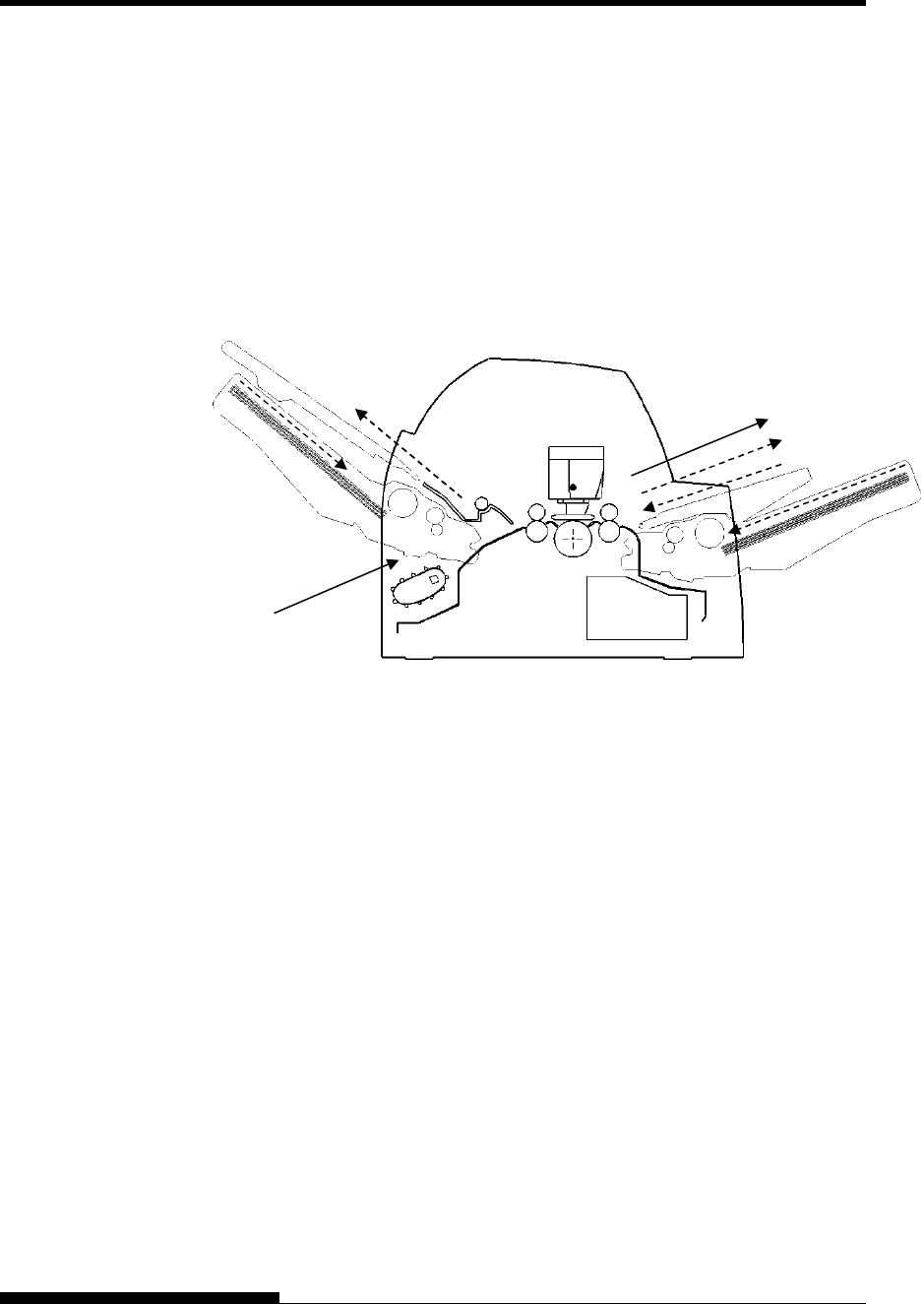
PAPER HANDLING
3-8 User's Manual
With rear tractor and front and rear optional cut sheet feeder
and large stacker. In addition, the front and rear tractor (either is
optional) can be mounted.
(2) Rear tractor Print Front eject
(3) Paper table Print Paper table
(4) Paper table Print Rear stacker
(5) Front cut sheet feeder Print Paper table
(6) Front cut sheet feeder Print Rear stacker
(7) Rear cut sheet feeder Print Paper table
(8) Rear cut sheet feeder Print Rear stacker
NOTES
When remaining the ejected cut sheet on the paper table, the
REMOVE PAPER indicator blinks and the printer stops printing.
Before restarting printing, be sure to remove the cut sheet.
You must remove cut sheets one by one immediately after ejection.
This is required because the printer may load an ejected sheet again
or an ejected sheet may push the previous sheets out of the printer.
To eject sheets larger than A4 size onto the paper table, the paper
table must be replaced with the optional large cut sheet table to
prevent ejected sheets from falling off the paper table.
When printing thin paper, multipart copy paper, or large size paper,
frequently remove the paper from the rear stacker or the paper table.
(2)
[2] [3][5][7]
(3)(4)
[4]
(7)(8) [8]
(5)(6)
[6]
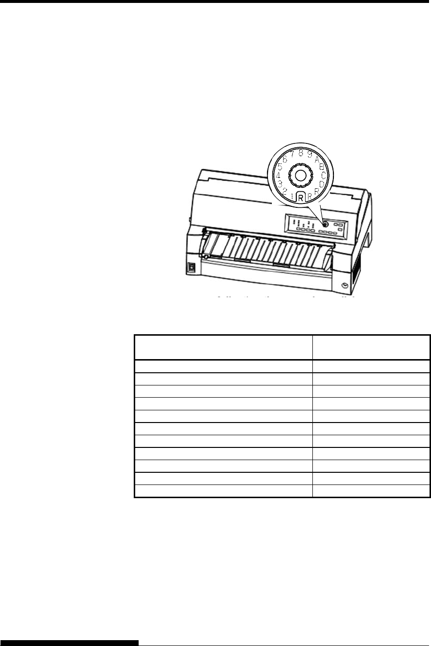
PAPER HANDLING
User's Manual 3-9
The printer can handle paper of different thicknesses, including multipart
forms with up to nine parts (original plus eight copies). For details on
paper thickness specifications, see Appendix B.
The printer automatically adjusts for different paper thicknesses.
You can use the MANUAL GAP DIAL to adjust the paper thickness
manually at manual mode. To place printer manual mode, press AUTO
GAP button 2 seconds or more so that AUTO GAP lamp is off.
Adjusting the manual gap dial
Table 3.2 Manual Gap Dial Settings (LED)
Number of Copies
(Including the Original) *1 Setting *2
1 copy 1
2 copies 2
3 copies 3
4 copies 4
5 copies 5
6 copies 6
7 copies 7
8 copies 8
9 copies, Envelopes A
Slips B, C, D
Ribbon replacement R
*1 For carbon-interleaved paper, the carbon counts as one copy.
*2 Vary the setting up or down (including A to R) to optimize printing
especially for labels and envelopes. Select R when replacing a
ribbon or clearing a paper jam.
NOTE
If printing is messy, the ribbon miss-feeds, or the paper jams, move
the manual gap dial one setting higher.
ADJUSTING FOR
PAPER THICKNESS
(LED)
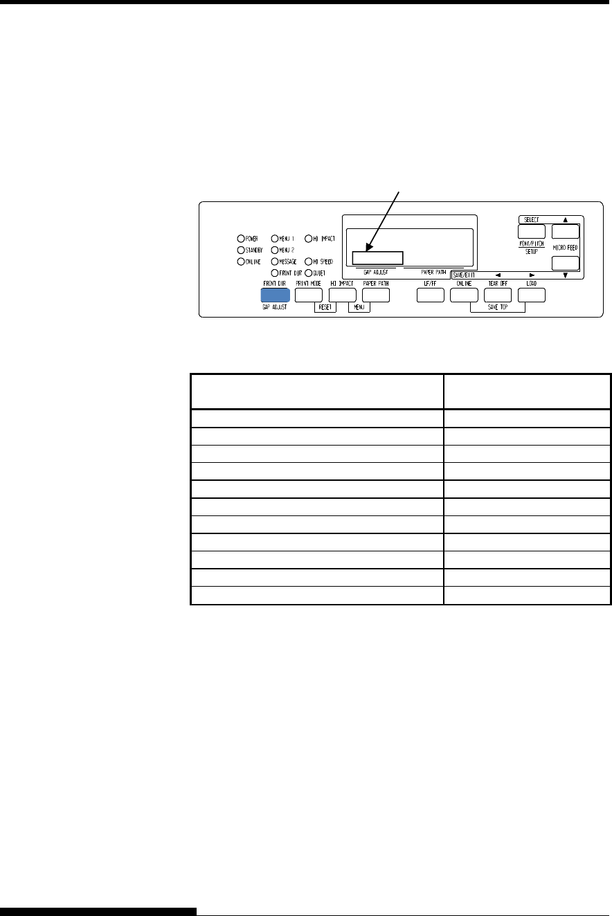
PAPER HANDLING
3-10 User's Manual
The printer can handle paper of different thicknesses, including multipart
forms with up to nine parts (original plus eight copies). For details on
paper thickness specifications, see Appendix B.
The printer automatically adjusts for different paper thicknesses.
You can use the GAP ADJUST button to adjust the paper thickness
manually.
Adjusting the manual gap
Table 3.3 Manual Gap Settings (LCD)
Number of Copies
(Including the Original) *1 Setting *2
1 copy GAP-1
2 copies GAP-2
3 copies GAP-3
4 copies GAP-4
5 copies GAP-5
6 copies GAP-6
7 copies GAP-7
8 copies GAP-8
9 copies, Envelopes GAP-9
Slips GAP-A,B,C
Ribbon replacement GAP-D
*1 For carbon-interleaved paper, the carbon counts as one copy.
*2 Vary the setting up or down (including A to D) to optimize printing
especially for labels and envelopes. Select D when replacing a
ribbon or clearing a paper jam.
NOTE
If printing is messy, the ribbon miss-feeds, or the paper jams, move
the manual gap one setting higher.
ADJUSTING FOR
PAPER THICKNESS
(LCD)
Area for Gap adjust value
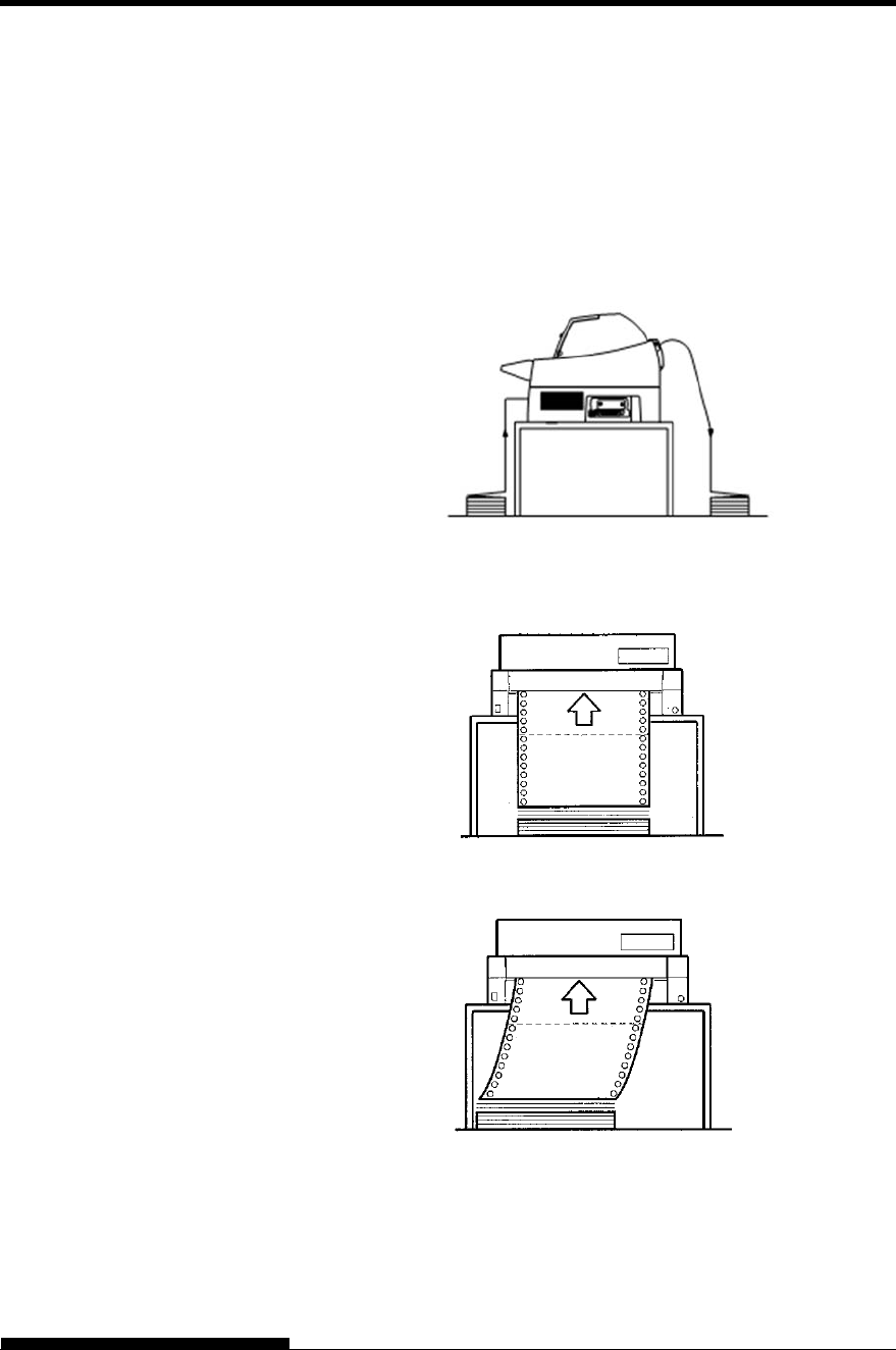
PAPER HANDLING
User's Manual 3-11
Continuous forms paper, fan-folded at the horizontal perforations, is
ideal for printing rough drafts and long files. The paper is fed into the
printer using the forms tractors.
Positioning the Paper Stack
Place the stack of continuous forms paper directly below the rear of the
printer or below the front of the printer. After the paper is installed in the
printer, the paper path should look like this:
Good placement
Bad placement
Placement of continuous forms
USING
CONTINUOUS
FORMS
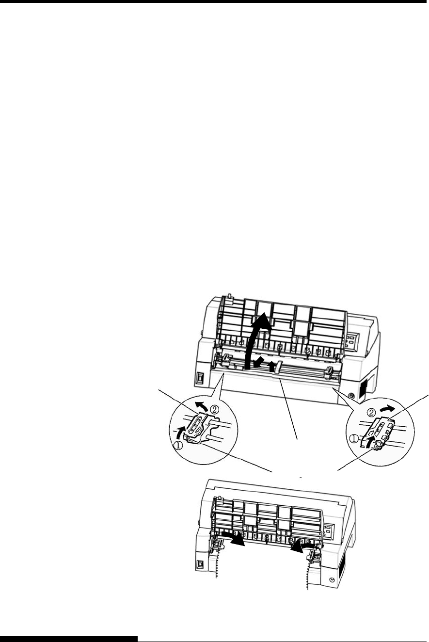
PAPER HANDLING
3-12 User's Manual
Loading Continuous Forms (Front Feed)
This section explains how to use continuous forms as the tractor unit is
installed at the front of the printer. The tractor unit pushes continuous
forms. This condition applies when you first purchase the printer.
Up to 8-ply media can be fed by the front tractor unit.
You can use continuous forms paper even if you have a cut sheet feeder
installed at the rear of the printer.
To load continuous forms paper:
1. Make sure that the printer is turned on. Remove any single-sheet
paper from the printer.
2. Lift up the paper table as shown below.
3. Release the tractor locking levers by pulling them up(①). Open
the tractor paper holders. See the following figure(②).
4. Position the tractors and center guide.
5. Fit the paper feed holes onto the left and right tractor pins.
Adjust the right tractor to the width of the form. Close the paper
holders.
Paper Holders Paper Holders
Locking Levers
Center Guide
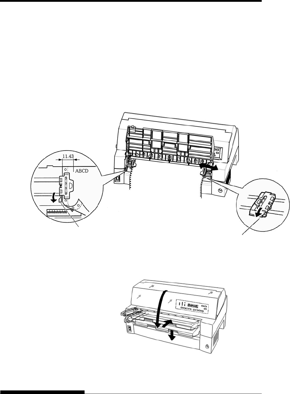
PAPER HANDLING
User's Manual 3-13
Set the continuous forms to front tractors
6. Adjust the left margin.
Below the left tractor, there is a tractor guide, short inch-based
ruler graduated in 10 columns per inch. Use the ruler to help
position the tractor. When the paper edge is positioned to the
zero line, the left margin is 12 mm (0.5 inch) including
perforation area and the arrow indicates the location of the first
character.
7. Pull the right tractor to stretch the paper taut. Push the right
locking lever down to secure the tractor in place.
Adjusting tractor position
8. Lower the paper table to the down position (normal mode).
Lowering the paper table
Locking Lever
Locking Leve
r

PAPER HANDLING
3-14 User's Manual
CAUTION
Before lowering the paper table, make sure that the paper holders
are closed.
If the holders are opened, they may cause damage to the tractors
and the paper table.
Make sure that the paper table is positioned to its normal mode. If
it is not done, jamming may occur when continuous forms paper is
fed.
9. Press the PAPER PATH button to select “FRONT TRACTOR”.
(The indicator lights.)
10. Press the LOAD button to advance the paper to the top-of-form
position. Top-of-form is the first line on which printing can start.
After loading paper, the printer goes into online mode.
11. Print a sample page and check the page margins. Make the
following adjustments, as necessary:
Horizontal alignment. Move the forms tractors as required.
Top-of-form setting (see Chapter 5).
Margin settings. Use your software or the printer setup
mode (see Chapter 5).
NOTE
Do not open the front cover during printing.
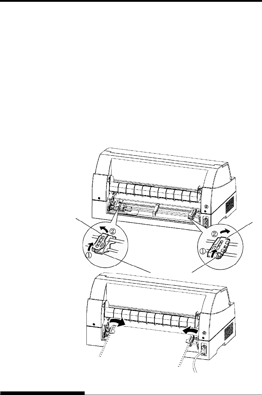
PAPER HANDLING
User's Manual 3-15
Loading Continuous Forms (Rear Feed)
A tractor is supplied as standard and is attached to the front of the printer.
It can be attached to the rear of the printer. You can also buy a tractor
unit as an additional rear tractor unit.
A maximum of 8-ply media can be fed from the rear tractor unit.
For reinstalling the tractor unit for rear feed, see page 2-10 to 2-13.
1. Release the tractor locking levers by pulling them up(①). Open
the tractor paper holders. See the following figure(②).
2. Position the tractors and center guide.
3. Fit the paper feed holes onto the left and right tractor pins.
Adjust the right tractor to the width of the form. Close the paper
holders.
Locking Levers
Paper Holder Paper Holder
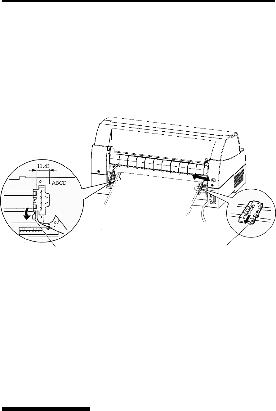
PAPER HANDLING
3-16 User's Manual
4. Adjust the left margin.
Below the left tractor, there is a tractor guide, short inch-based
ruler graduated in 10 columns per inch. Use the ruler to help
position the tractor. When the paper edge is positioned to the
zero line, the left margin is 12 mm (0.5 inch) including
perforation area and the arrow indicates the location of the first
character.
5. Pull the right tractor to stretch the paper taut. Push the right
locking lever down to secure the tractor in place.
6. Press the PAPER PATH button to select REAR TRACTOR (the
indicator lights).
7. Press the LOAD button to advance the paper to the top-of-form
position. Top-of-form is the first line on which printing can start.
After loading paper, the printer goes into online mode.
8. Print a sample page and check the page margins. Make the
following adjustments, as necessary:
Horizontal alignment. Move the forms tractors as required.
Top-of-form setting (see Chapter 5).
Margin settings. Use your software or the printer setup
mode (see Chapter 5).
Lock Lever Lock Lever

PAPER HANDLING
User's Manual 3-17
Unloading Continuous Forms
To unload continuous forms:
1. Make sure that the FRONT TRACTOR or REAR TRACTOR
indicator lights.
2. Press the LOAD button. The continuous forms paper is retracted
to the park position. If the paper cannot be retracted in one
operation, continue to press the LOAD button until the paper is
parked.
NOTE
The printer can retract continuous forms paper up to a
maximum of 55.8 cm (22 inches) per operation.
3. To remove the paper, raise the tractor paper holders and lift out
the paper.
NOTE
If continuous forms are unloaded without stopping, the
paper may slip off the tractors.
Tearing Off Continuous Forms
Your printer has a special “tear-off edge” that allows you to tear off
printed pages without wasting paper. The tear-off edge is located on the
front and rear of the printer.
To tear off continuous forms using the tear-off edge:
1. Press the TEAR OFF button. The bottom perforation of the last
page advances to the tear-off edge. If you specified TEAR OFF:
AUTO using the HARDWARE function in setup mode, the
paper automatically advances to the tear-off edge at the end of
each job (or when the printer has printed all the data received).
NOTE
If the bottom perforation of your paper is not positioned at
the tear-off edge, the length of your paper may not be
specified correctly in your software or the printer setup
mode.
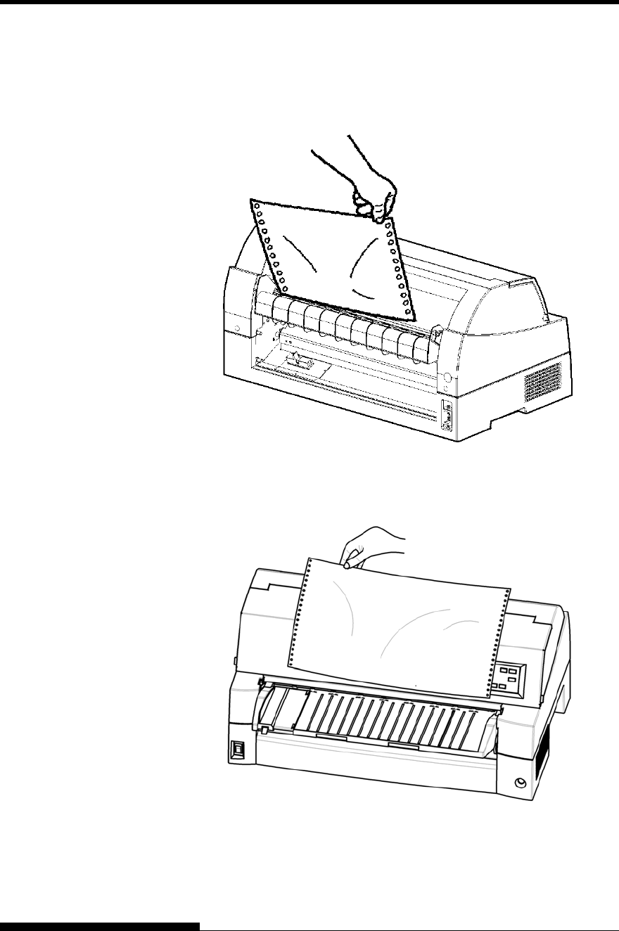
PAPER HANDLING
3-18 User's Manual
Check that the paper length is specified correctly. For
information on specifying page length using setup mode, see
Chapter 5.
2. Tear the paper off at the perforation.
Tearing off continuous forms (front feed)
Tearing off continuous forms (rear feed)
3. Press any button to retract the forms back to the top-of-form
position.

PAPER HANDLING
User's Manual 3-19
This section describes how to load paper from the paper table or cut sheet
feeder. The paper table allows paper to be loaded manually, one sheet at
a time. A cut sheet feeder allows paper to be loaded automatically from
the paper bin.
Loading a Paper From The Paper Table.
To load a sheet of paper from the paper table:
1. Make sure that the printer is turned on.
2. Press the PAPER PATH button to select CUT SHEET (the
indicator lights).
3. Press the FRONT DIR button to select the direction of ejecting
single sheets.
Front ejection — FRONTDIR indicator lights.
Rear ejection — FRONTDIR indicator doesn’t light.
4. Adjust the left margin.
On the left hand side of the paper table, a scale graduated in
units of 1 [mm]. When the paper guide is positioned at scale 0
[mm], the left margin is 5 mm (0.2 inch).
Push the lock lever down to secure the guide.
5. Pull the sub-guide out as required to the paper size.
NOTE
When using the paper whose width is under 100 mm (4 inch),
position the paper guide at scale 0 [mm].
USING SINGLE
SHEETS
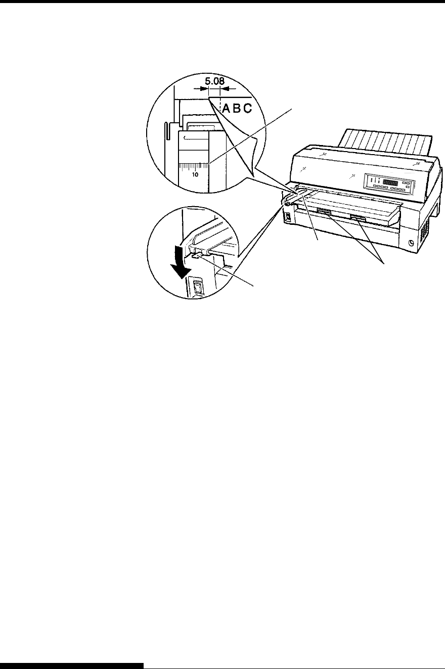
PAPER HANDLING
3-20 User's Manual
Preparing to load a sheet of paper
6. Insert a sheet of paper into the paper table. Make sure that the
front edge of the paper engages snugly with the feed roller.
NOTE
If paper skews when it is loaded, the printer does not print and ejects
the paper. (This function can be disabled by a setting in setup mode.)
0(zero)
Movable guide
Lock lever
Sub guide
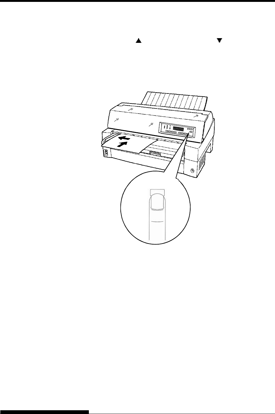
PAPER HANDLING
User's Manual 3-21
7. Press the LOAD button. The paper will advance to the top-of-
form position. The top-of-form position is the first line on which
printing can start. To adjust the position of the paper slightly,
press the MICRO FEED button or the MICRO FEED
button. The paper will move forward or backward in 1/180-inch
increments.
After loading paper, the printer goes into online mode.
Loading a sheet of paper
8. Print a sample page and check the page margins. Make the
following adjustments, as necessary:
Horizontal alignment. Readjust the paper guide if required.
Top-of-form setting (see Chapter 5).
Margin settings. Use your software or the printer setup
mode (see Chapter 5).
NOTE
Do not open the front cover during printing. With the cover open
detection option installed, the printer never prints while the front
cover is open. Close the front cover to perform printing.
LOAD
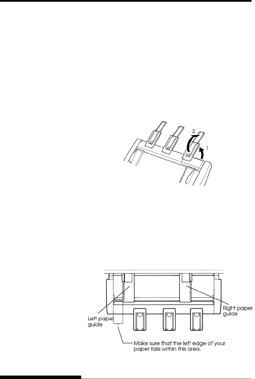
PAPER HANDLING
3-22 User's Manual
Loading Paper from the Cut Sheet Feeder
(Option)
A cut sheet feeder (SF940) allows automatic printing on single sheets
without the need to manually insert the sheets one-by-one. This can save
you a lot of time when printing long files using single sheets. See
Chapter 8 for more information on the cut sheet feeder.
For installation of the feeder, refer to its user’s manual. When a feeder is
mounted and the feeder cable is connected, the printer automatically
knows the feeder type and controls the feeder accordingly.
1. Two steps of extension are available for supporting long sheets
of paper.
Steps of extension
2. Adjust the left margin.
To help align the left paper guide, use the inch-based ruler
located behind the paper guides. The ruler is graduated in 10
columns per inch. For example, setting the left paper guide 12.7
mm (0.5 inch) from the left gives a left margin of 6.3 mm (0.25
inch) plus the left margin specified by your software or the
printer setup mode.
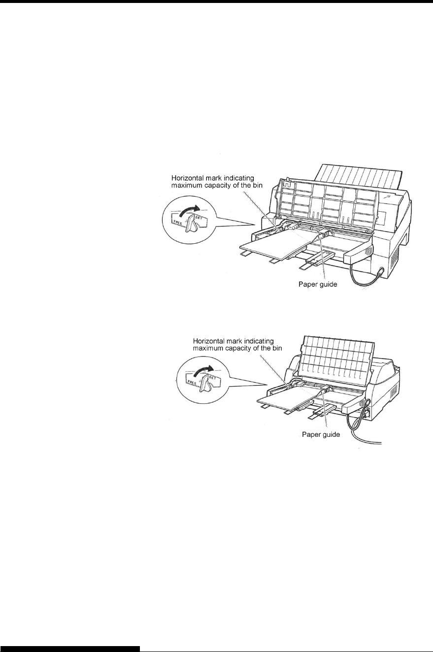
PAPER HANDLING
User's Manual 3-23
Slide the right paper guide until the distance between the
two guides is the approximate width of your paper.
3. Manually fan the stack of paper and place it in the paper bin.
NOTE
A short horizontal mark inside the left paper guide indicates
the maximum capacity of the bin. Make sure that your
paper stack does not exceed this horizontal mark.
Loading the cut sheet feeder (Front feed)
Loading the cut sheet feeder (Rear feed)
4. Readjust the right paper guide, leaving a slight gap between the
paper guide and the right edge of the paper. Slide the guide to
the approximate width of the paper, or the paper will not be
loaded properly. Pull the right locking lever forward.
5. Push the bin lever down to the “SET” position.
6. Load paper to the top-of-form position using either of the
following methods:

PAPER HANDLING
3-24 User's Manual
Load the paper manually. Press the LOAD button. The
paper will advance to the top-of-form position. Adjust the
position of the paper as needed by the MICRO button or
the MICRO button (micro feed).
Load the paper using your software. Press the ONLINE
button to place the printer online. Load paper according to
the instructions in your software documentation. Most
software packages load paper automatically.
After loading paper, the printer goes into online mode.
7. Print a sample page and check the page margins. Make the
following adjustments, as necessary:
Horizontal alignment. Readjust the paper guides if required.
Top-of-form setting (see Chapter 5).
Margin settings. Use your software or the printer setup
mode (see Chapter 5).
NOTE
Do not open the front cover during printing.
Ejecting Single Sheets
If you print using software, each sheet is ejected automatically when the
end of the printed page is reached. To manually eject sheets of paper, use
the following method:
Press and hold down the LF/FF button to execute a forward
form feed.

PAPER HANDLING
User's Manual 3-25
The following functions are available whether the printer is online or
offline.
Line Feed/Form Feed
Use the line feed/form feed function to move paper forward.
Pressing and holding down the LF/FF button feeds one sheet of
paper.
Pressing the LF/FF button once advances the paper one line (do
not hold the button more than three seconds).
Micro Feed
Use the micro feed function to fine tune the position of the paper.
Press the MICRO button to feed paper backward by 1/180
inch.
Press the MICRO button to feed paper forward by 1/180 inch.
Remember that the top-of-form will differ from the original setting.
Load Position Adjust
Use also the micro feed function to adjust the load position of the paper.
When the MICRO button or the MICRO button is used
immediately after the LOAD button is pressed, the adjusted
position of paper is retained as the new load position until the
power is turned off.
Pressing the ONLINE and LOAD buttons simultaneously saves
the new position permanently.
The load position can be set for single sheets and continuous forms
respectively.
FEEDING AND
POSITIONING
PAPER
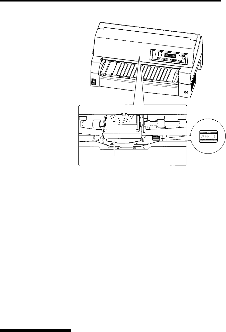
PAPER HANDLING
3-26 User's Manual
Adjusting Load Position by Using Window of Card Guide
The lines of window on the right side of card guide indicate printing line.
So use this as a guide to adjust load position.
Print Head

PAPER HANDLING
User's Manual 3-27
General Tips
Use high-quality paper. Do not use paper that is wrinkled or
curled at the edges.
Do not use paper with staples or metal parts.
Do not use paper with unpredictable variations in thickness,
such as paper with partial multilayers, paper with embossed
printing, and labels with the backing sheet exposed.
Store paper in a clean, dry environment.
Multipart Forms
Avoid using carbon-interleaved single sheets if possible.
Printing tends to become misaligned on the bottom sheet.
To ensure smoother feeding of paper-stapled, multipart forms,
raise the rear stacker to support the forms.
Envelopes
When printing envelopes, use the paper table or the manual feed
slot of the cut sheet feeder. Note the following:
- When loading envelopes, make sure that the envelope flaps
face forward. Otherwise, the envelopes may jam in the
printer.
Labels
Be careful to check operating conditions when using labels.
Labels are sensitive to temperature and humidity.
Only use labels mounted on continuous forms backing sheets.
Do not print labels mounted on single sheet backing. Labels
mounted on single sheet backing tend to slip and printing
becomes crooked.
Do not feed labels backwards using the LOAD button from the
control panel. Jamming may occur.
Do not use the printer tear-off feature when printing labels. If
the labels are retracted, the backing may peel off and the labels
may jam in the printer.
Test-print labels before running a job. If jams occur, go into
setup mode and
- set the paper thickness control to manual mode and
- set the paper thickness indicator to a wider position
manually.
If jamming problems continue, try a different type of label.
TIPS ON PAPER
HANDLING
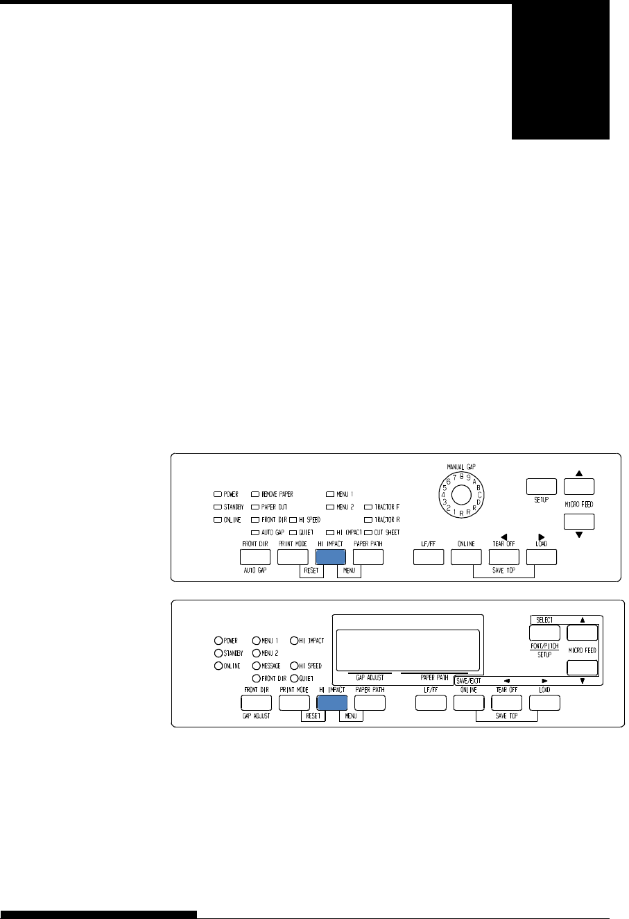
User's Manual 4-1
4
CHAPTER 4 PRINTING
PRINTING
This chapter describes the following everyday
printing operations:
Using multipart form (high impact mode)
Selecting the print mode(quiet mode)
Starting, stopping, or resuming printing
Removing printed pages
Clearing the print buffer
Selecting the print features
Instructions for loading paper are given in Chapter 3.
This printer has enough capability to print multipart forms. When
superior copy capability is required, use the HI IMPACT mode. Press
the HI IMPACT button on the printer control panel. This function is
valid when the HI IMPACT indicator lights.
Print control panel
NOTE
Setting HI IMPACT mode by pressing the HI IMPACT button is
cancelled when you turn off the printer.
If you wish to have the HI IMPACT mode set on power-on, save
the setting in setup mode.
MULTIPART FORMS
(HI IMPACT MODE)
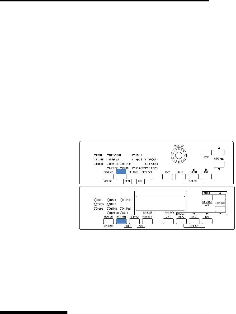
PRINTING
4-2 User's Manual
It has three print modes in this printer.
・STANDARD MODE
・HI SPEED MODE
Horizontally consecutive dots are omitted (LQ), and the printer
stpeed is twice as STANDARD MODE .
・QUIET MODE
The consecutive dots are omitted (LQ).
The print speed is slowed to LQ speed (except for LQ).
Skipping the space (no characters) at higher speed doesn’t work.
To select Print mode:
1. If the PRINT MODE button is pressed at STANDARD MODE
(Both HI SPEED indicator light and QUIET indicator light are
turned off), it becomes HI SPEED MODE. At this time, the HI
SPEED indicator lights.
2. If the PRINT MODE button is pressed at HI SPEED MODE, HI
SPEED MODE is released, and it becomes QUIET MODE. At
this time, the QUIET indicator lights .
3. If the PRINT MODE button is pressed at QUIET MODE, the
QUIET mode is released, and it becomes STANDARD MODE.
Print control panel
NOTE
Setting quiet mode by pressing the PRINT MODE button is
cancelled when you turn off the printer.
If you wish to have the quiet mode set on power-on, save the
setting in setup mode.
PRINT MODE(HI
SPEED MODE/QUIET
MODE)

PRINTING
User's Manual 4-3
Starting Printing
Before you start to print, make sure that paper is loaded.
To start printing, press the ONLINE button to place the printer online.
Then start your software.
Stopping Printing
To stop printing immediately, press the ONLINE button to place the
printer offline. You can also use your software to stop printing, but there
will be a slight delay before printing stops. Any data sent to the print
buffer but not yet printed is stored until you resume printing. Data in the
print buffer is lost if you turn the printer off.
To resume printing, press the ONLINE button again. To cancel printing,
use the cancel commands provided by your software or computer. To
clear the print buffer, place the printer offline and press the PRINT
MODE and HI IMPACT buttons. Any data sent to the print buffer before
you canceled printing will be lost.
Resuming from a Paper-Out
The printer can “sense” when paper runs out. Depending upon how PPR-
OUT (paper-out) is set in setup mode, the printer either:
Stops printing and lights the red PAPER OUT indicator, or
Continues printing until no more data remains in the printer.
See Chapter 5 for details on setting PPR-OUT. The factory default is to
stop printing if continuous forms paper runs out and to continue printing
if single sheet paper runs out.
To resume printing when paper runs out, use either of the methods
described below:
Printing the remaining lines on a page
This method is convenient to continue printing under the paper-out
condition, but is not available when the cut sheet feeder is used.
1. Press the ONLINE button. The printer returns to online mode,
prints or feeds one line, and the PAPER OUT indicator lights up
again.
2. Repeat this procedure until the full page is printed. Line
spacing , however, may be uneven.
STARTING OR
STOPPING
PRINTING

PRINTING
4-4 User's Manual
CAUTION
When printing remaining lines, be careful not to print on the platen.
Printing on the platen may damage both the platen and the print head.
Continuing printing after supplying paper
1. Install paper on the forms tractors or on the cut sheet stand, or in
the cut sheet feeder bin, as described in Chapter 3.
2. To load the first sheet of paper, press the LOAD button. The
PAPER OUT indicator will turn off.
3. Press the ONLINE button to place the printer online. The printer
resumes printing.
NOTE
For continuous forms paper, the page where printing
stopped and the page where printing resumes may be
incorrectly printed. In this case, wait for the entire job to
finish printing. Then reprint the incorrect pages.

PRINTING
User's Manual 4-5
This section describes the best methods for removing single sheets or
continuous forms paper after printing.
Removing Single Sheets
When you print using software, the printer automatically ejects each
sheet of paper when the end of the printed page is reached. To eject
sheets manually, use one of the following methods:
Press and hold down the LF/FF button to execute a form feed.
Removing Continuous Forms
To avoid wasting paper, use the printer tear-off function to remove
continuous forms paper. Press the TEAR OFF button to advance the
perforation to the tear-off edge. Tear the paper off, and then press any
button to retract the paper back to the top-of-form position. See Chapter
3 for more detailed instructions.
Place the printer offline. Press the PRINT MODE and HI IMPACT
buttons simultaneously to clear all data from the print buffer. This
method is useful when you cancel a print operation and do not want to
continue printing data already sent to the printer.
This method does not change or clear MENU1 and MENU2 settings,
paper loading position settings, and downloaded fonts.
REMOVING
PRINTED PAGES
CLEARING THE
PRINT BUFFER

PRINTING
4-6 User's Manual
The print features you select determine how your printed pages will look.
Print features include the following:
Print quality
Fonts
Pitch (characters per horizontal inch)
Page length and width
Line spacing (lines per vertical inch)
To select print features, you can use either commercial software or the
printer control panel. The method you use depends on the capabilities of
your software. If your software has most of the features you require, you
may rarely – if ever – have to use the control panel. In fact, your software
often overrides the printer settings.
If your software has limited options, you can use the printer control panel
to select print features. Sometimes, the control panel enables you to
select features not available through your software. For example, you can
select downloaded fonts not supported by your software.
Using Commercial Software
Many commercial software packages offer a wide variety of print
features, including some features that are not supported by this printer.
For example, software often provides a wider range of font sizes than the
printer can accommodate. Software also allows you to specify multiple
fonts on a page.
To determine which features your software supports and how to select
them, refer to your software documentation.
SELECTING PRINT
FEATURES
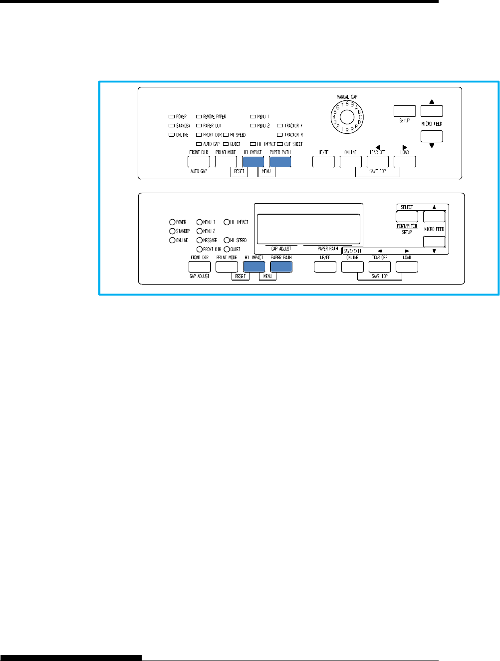
PRINTING
User's Manual 4-7
Using the Control Panel
Use the PAPER PATH and HI IMPACT button to directly select one of
the two menus.
Printer control panel
The PAPER PATH and HI IMPACT buttons specify MENU1 or
MENU2, either of which allows you to specify different sets of options
in advance. Some of the print features include emulation, print quality,
character pitch, and line spacing. To setup the print features to MENU1
and MENU2, refer to the chapter 5.
When you first turn the printer on, the MENU 1 indicator is lit; that is, all
of the print features assigned to MENU1 are enabled. However, you can
easily switch to MENU2 before printing.
NOTE
For easy reference, keep a list of your current MENU 1 and MENU 2
settings near the printer. To print a list of current settings, see the
section Printing a List of Selected Options in Chapter 5. You may
also want to use the space provided in Table 4.1 to record your
settings.
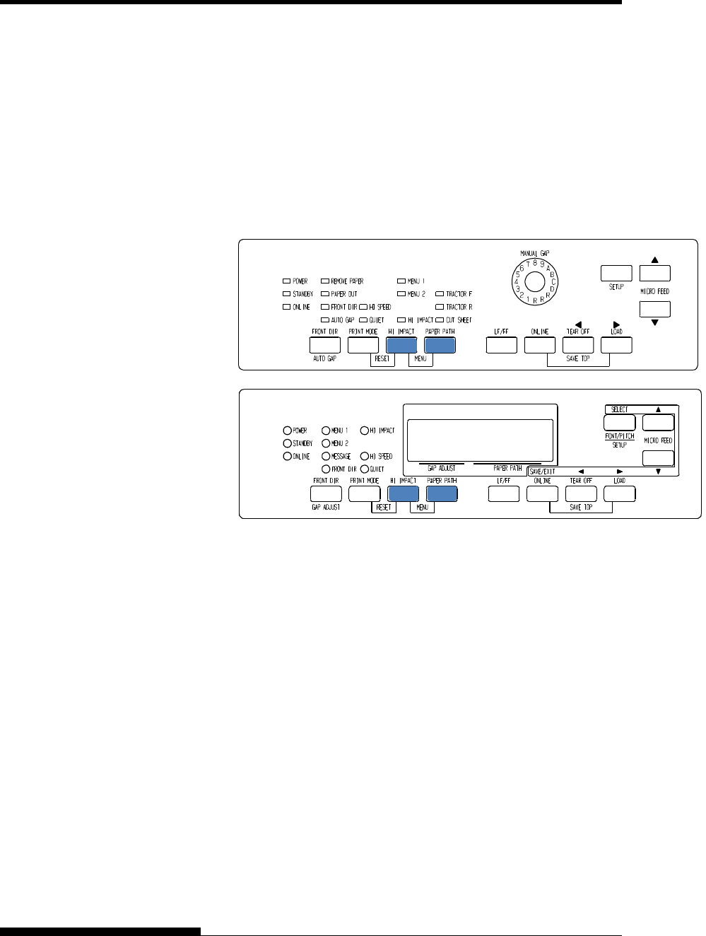
PRINTING
4-8 User's Manual
Selecting MENU1 or MENU2
When you first turn the printer on, MENU1 is selected. To change to
MENU2 or back to MENU1, proceed as follows:
1. Press the ONLINE button to place the printer offline.
2. Repeatedly press the PAPER PATH and HI IMPACT buttons.
The lighted indicator (1 or 2) shows the menu selected. When
the menu selection is changed, the font (font, pitch, and quality)
assigned in the selected menu becomes valid.
3. Press the ONLINE button to return online. You are ready to
print using the selected menu.
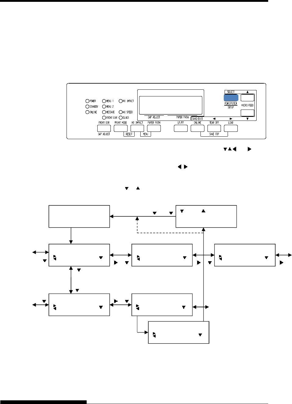
PRINTING
User's Manual 4-9
Using the Control Panel (LCD type only)
LCD type Control panel also can select print features including
FONT/PITCH/QUALITY that assigned current MENU1 or 2 directly.
To select print features enter select mode as follows.
1. Press the ONLINE button to place the printer online.
2. Press the FONT/PITCH button to enter select menu.
3. To move layer and in transverse direction, use , , and
buttons.
4. To select print features, use , and SELECT buttons.
5. To save or exit press SAVE/EXIT buttons.
6. Press or buttons to finish.
FONT/PITCH/QUAL setting mode.
ONLINE
AUTO TRACTOR F
FONT/PITCH/QUAL
FONT
FONT/PITCH/QUAL
PITCH
FONT/PITCH/QUAL
QUALITY
FONT
*COUR 10
FONT
PRSTG12
FONT
*PRSTG12
FONT/PITCH butto
n
SELECT SW
:SAVE :CANCEL
SAVE/EXIT button
or
“*” is applied to a selected option.
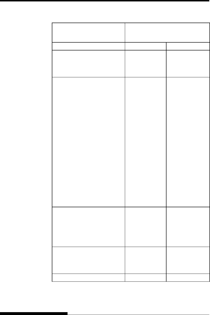
PRINTING
4-10 User's Manual
Table 4.1 MENU1 and MENU2 Settings
Setting Default Settings
For easy reference, check (
) or record
your default settings in the space below.
Print Feature MENU1 MENU2
Emulation
Fujitsu DPL24C PLUS
IBM Proprinter XL24E
Epson ESC/P2
Font
Courier 10
Prestige Elite 12
Compressed 17
Boldface PS
Pica 10
Correspondence
OCR-B 10
OCR-A 10
Courier Normal 10 (outline)
Courier Bold 10 (outline)
Courier Italic 10 (outline)
Nimbus Sans Normal PS (outline)
Nimbus Sans Bold PS (outline)
Nimbus Sans Italic PS (outline)
Timeless Normal PS (outline)
Timeless Bold PS (outline)
Timeless Italic PS (outline)
Downloaded font 0
Downloaded font 1
Print quality
Letter
Report
Draft
High-speed draft
Super high-speed draft
Pitch
2.5, 3, 5, 6, 10, 12
15, 17, 18 or 20 cpi
Proportional spacing
Other features:

User's Manual 5-1
5
CHAPTER 5 USING SETUP MODE
USING SETUP MODE
Your printer has two modes: normal and setup.
Normal mode is used for everyday printer operations
and is explained in Chapters 3 and 4.
Setup mode serves two purposes. It enables you to:
Select the printer’s optional settings
Help diagnose printer problems
These setup mode functions can be done either offline, using the printer
control panel (offline setup), or remotely, using a setup program in your
computer system or software (online setup). Primarily, this chapter
explains how to use the offline setup mode. The online setup mode,
which is reviewed briefly at the end of this chapter, is valid in all
emulations.
Optional settings on the printer include the emulation, fonts, pitch, page
length and page width, serial interface options, and the top-of form
setting. When you save your settings in the printer’s permanent memory,
they become the new settings or defaults. These defaults are invoked
whenever you turn on the printer. For example, if you save DPL24C
PLUS as the default emulation, DPL24C PLUS is invoked when you turn
on the printer.
The printer diagnostic functions are SELF-TST, HEX-DUMP, and
V-ALMNT. These functions are helpful for printer trouble-shooting, as
described in Chapter 7.
The sections in this chapter are presented in logical sequence. If you are
a first-time user, be sure to read the following sections first:
Entering Setup Mode
Overview of Setup Mode
These sections will familiarize you with how setup mode works. Once
you understand the basics, use the following sections to select printer
options that are compatible with your computer system’s hardware and
software setup:
Printing a List of Selected Options
Deciding Which Options to Change
MENU1 and MENU2 Items and Options
Hardware Items and Options
Print Position Adjustment Items and Options
Configuration Items and Options
HOW TO USE THIS
CHAPTER
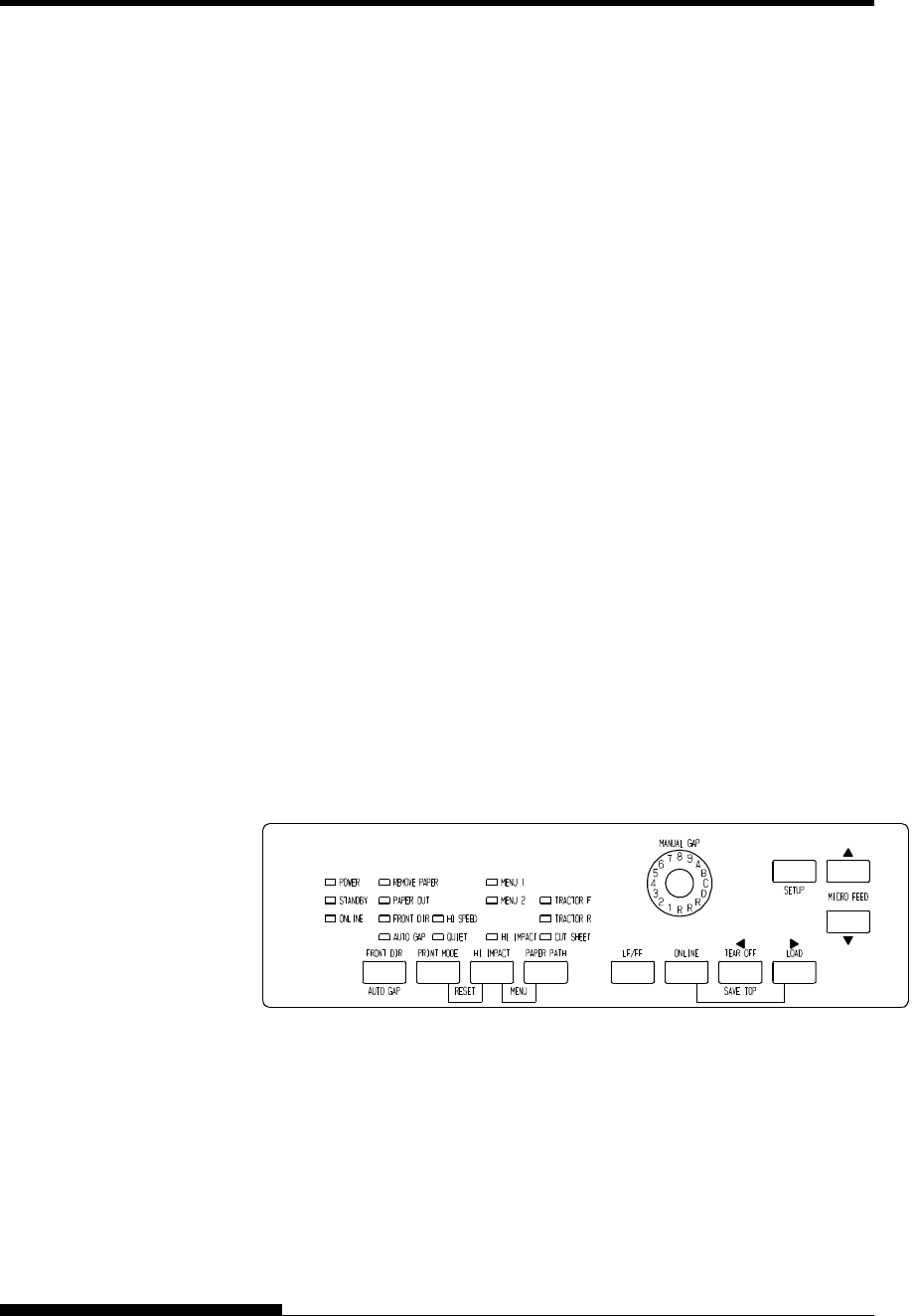
USING SETUP MODE
5-2 User's Manual
Head Gap Adjustment Items and Options
Exiting and Saving
To restore the printer default settings (factory defaults or power-on
defaults), see the section Resetting Defaults later in this chapter.
For information on using the SELF-TST, HEX-DUMP, and V-ALMNT
functions, see the section Using the Diagnostic Functions later in this
chapter.
For Experienced Users:
Once you are familiar with setup mode, you may want to use the
flowchart at the end of this chapter for quick reference. The flowchart
lists all printer setup functions, items, and options.
Before entering setup mode, load continuous forms paper from the front
tractor into the printer as described in Chapter 3. Several sheets of paper
may be required to make all of your setup mode selections.
To enter setup mode, follow these steps:
1. Make sure that front continuous forms paper is loaded and press
the PAPER PATH button to select the appropriate paper path.
If continuous forms paper is fed from the rear or a CSF is
mounted, the printer does not enter SETUP mode.
2. Press the ONLINE button to place the printer offline.
3. Press the SETUP buttons until the printer beeps.
Entering setup mode
イラスト変更済
If you do not hear a beep or an alarm beep (beeps four times),
you are not in setup mode. Place the printer offline and try again.
ENTERING SETUP
MODE(LED)
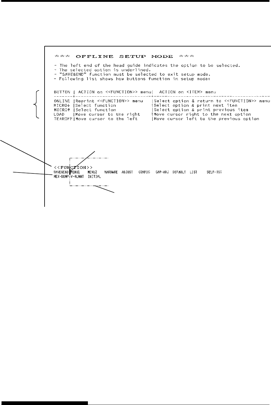
USING SETUP MODE
User's Manual 5-3
4. When the printer enters offline setup mode, it prints the
following information.
Initial printout in setup mode
The initial printout contains a header, help menu, and <<FUNCTION>>
menu. The header tells you that the printer is offline and in setup mode.
The help menu provides a quick summary of how to use setup mode. The
<<FUNCTION>> menu lists all of the functions available to you in setup
mode. Note that the cursor on the left edge of the aluminum print guide is
initially positioned at the SAVE & END function.
Setup mode can also be entered by turning off the printer, then turning
the printer back on while pressing the SETUP button until the printer
beeps.
Function buttons in
Setup mode
<<Function>> menu
Function
Card guide (aluminum print guide (head guide))
Cursor
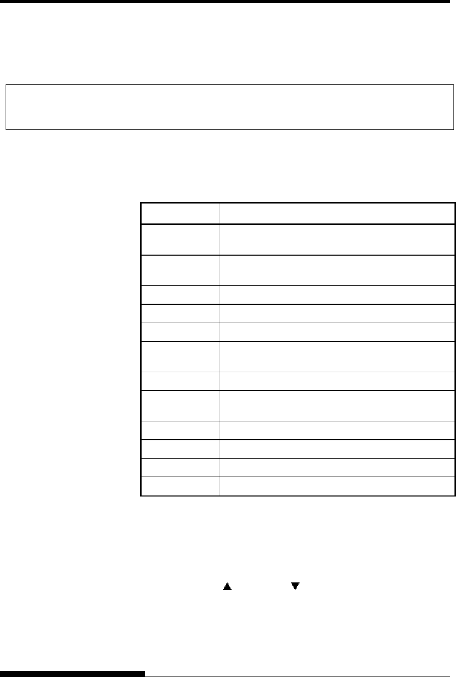
USING SETUP MODE
5-4 User's Manual
When you enter setup mode, the following <<FUNCTION>> menu is
printed:
<< FUNCTION >>
SAVE&END MENU1 MENU2 HARDWRE ADJUST CONFIG GAP-ADJ DEFAULT LIST SELF-TST
HEX-DUMP V-ALMNT INITIAL
Table 5.1 summarizes the purpose of each function.
Table 5.1 Setup Mode Functions
Function Purpose
SAVE & END Exits setup mode and saves any changes made while
in setup mode.
MENU1 and
MENU2
Assigns print features to MENU1 and MENU2 on the
printer control panel.
HARDWRE Changes the printer hardware options.
ADJUST Changes the print position adjustment options.
CONFIG Changes the configuration options.
GAP-ADJ Adjust the gap between the print head and printing
paper.
DEFAULT Resets factory defaults in MENU1 and MENU2.
INITIAL Resets factory defaults in MENU1, MENU2,
HARDWRE, ADJUST, CONFIG, GAP-ADJ.
LIST Prints a list of all currently selected options.
SELF-TST Runs the self-test.
HEX-DUMP Prints hex dumps.
V-ALMNT Checks and corrects vertical print alignment.
To select a function from the <<FUNCTION>> menu:
1. Repeatedly press the “TEAR OFF” or “LOAD” button to
position the cursor on the left edge of the aluminum print guide
at the function you require.
2. Press the button or the button to select the function. If the
function has items and options, the printer prints the first item
and its options. The MENU1, MENU2, HARDWRE, ADJUST,
CONFIG, and GAP-ADJ functions contain items that have
selectable options. The other functions have neither items nor
options.
OVERVIEW OF
SETUP MODE (LED)
USING SETUP MODE
User's Manual 5-5
The first three MENU1 items and their options are shown below.
Items are enclosed in single brackets < >. A short underlined
portion is current option and long underlined portion is selected
option.
< EMULATE>DPL24C+ XL24E ESC/P2
<FONT >
COUR 10 PRSTG12 COMPRSD BOLDFCE PICA 10 CORRESP OCR-B OCR-A COUR-N COUR-B
COUR-I N.SAN-N N.SAN-B N.SAN-I TIMLS-N TIMLS-B TIMLS-I DOWNLD0 DOWNLD1
<QUALITY>LETTER REPORT DRAFT HI-DRFT SH-DRFT
To select an option from the <item> menu:
1. Repeatedly press the “TEAR OFF” or “LOAD” button to
position the cursor on the left edge of the aluminum print guide
at the option you require.
2. Press the button to select the option. The printer prints the
next item and its options. You can press to select the option.
Then, the printer prints the previous item and its options.
3. After selecting the desired options, press the ONLINE button to
reprint the <<FUNCTION>> menu.
For each item, the short-underlined option is the current default
option (the option currently saved in the printer’s permanent
memory). In the previous example, the default options are
Fujitsu DPL24C PLUS emulation, Courier 10 font, and letter
print quality.
Setup Mode Example (LED)
To become familiar with setup mode, try the following example. This
example shows how to change the font and pitch in MENU2 to Prestige
Elite 12 and 12 cpi.
1. Load continuous forms paper.
2. Enter setup mode.
Press the SETUP button until the printer beeps.
3. Select the MENU2 function.
Wait for the printer to stop printing and press the “TEAR OFF”
or “LOAD” button twice to position the cursor on the left edge
of the aluminum print guide at MENU2. Press the “ ” button
or the “ ” button to select the MENU2 function and print the
<EMULATE> item and its options.

USING SETUP MODE
5-6 User's Manual
4. Select the current emulation.
Since you do not want to change the emulation, press the “ ”
button to select the current emulation and print the next item,
<FONT> and its options.
5. Change the font to Prestige Elite 12.
Press the “TEAR OFF” or “LOAD” button once to position the
cursor on the left edge of the aluminum print guide on
PRSTG12. Press the “ ” button to select PRSTG12 and print
the next item, <QUALITY>, and its options.
6. Select the current print quality.
Since you do not want to change the print quality, press the
button to select the current print quality and print the next item,
<PITCH>, and its options.
7. Change the pitch to 12 cpi and exit the MENU2 function.
Press the “TEAR OFF” or “LOAD” button once to position the
cursor on the left edge of the aluminum print guide on 12 CPI.
Since you do not want to make any other changes in MENU2,
press the ONLINE button to select 12 CPI and exit MENU2.
The <<FUNCTION>> menu is then reprinted.
8. Exit setup mode, saving the new font and pitch.
Since the cursor on the left edge of the aluminum print guide is
on SAVE & END, press the MICRO FEED button or the
MICRO FEED button to select SAVE & END. The printer
saves Prestige Elite 12 and 12 cpi as the new power-on defaults
in MENU2. The printer then exits setup mode and returns
online. These settings remain in effect until changed.

USING SETUP MODE
User's Manual 5-7
Points to Remember
Whenever you enter setup mode, short help menus are printed at
the top of the page. Help menus are also printed when you select
the SELF-TST, HEX-DUMP, or V-ALMNT functions.
Use help menus for quick reference while in setup mode.
When printing the items and options for each function, you can
only print one item at a time. However, you can move either
forward or backward in the item list. To move forward (print the
next item), press the button. To move backward (print the
previous item), press the button.
While in the <<FUNCTION>> menu or when selecting a
function that contains items and selectable options, press the
ONLINE button to reprint the <<FUNCTION>> menu.
A short underline under the first two letters of an option
indicates that it is the current default setting. For example, 12
CPI indicates that 12 characters per inch is the default pitch.
To change the default, select and save a new pitch setting.
While in setup mode, you can use the LIST function to print out
a list of the currently selected options (see the next section for
details).
To exit setup mode and permanently save your changes, select
the SAVE & END function. For details, see the section Exiting
and Saving later in this chapter. To exit setup mode without
saving your changes, turn the printer off. Your previous power-
on defaults are active when you turn the printer on again.
The LIST function prints a list of all the printer’s currently selected
options. This function is useful for checking the printer settings when
you first enter setup mode or just before you exit. To print a list of
options, load continuous forms paper and then proceed as follows:
1. Enter setup mode.
Press the SETUP button until the printer beeps. Wait for the
printer to stop printing and check that the following
<<FUNCTION>> menu is printed:
<< FUNCTION >>
SAVE&END MENU1 MENU2 HARDWRE ADJUST CONFIG GAP-ADJ DEFAULT LIST SELF-TST
HEX-DUMP V-ALMNT INITIAL
PRINTING A LIST OF
SELECTED
OPTIONS(LED)

USING SETUP MODE
5-8 User's Manual
2. Select the LIST function.
Repeatedly press the “TEAR OFF” or “LOAD” button to
position the cursor on the left edge of the aluminum print guide
on LIST. Next press the button or the button to select the
LIST function. The printer starts to print a list of the currently
selected options. The preselected factory settings, also called
factory defaults, are shown on the opposite page.
When the printer finishes printing the list of options, it reprints
the <<FUNCTION>> menu.
3. Do either of the following:
Select another function, or
Exit setup mode, saving any changes you made.
For details about other functions, see the other sections in this
chapter. To exit setup mode and save your changes, make sure
that the cursor on the left edge of the aluminum print guide is
positioned on SAVE & END, then press the button or the
button.
USING SETUP MODE
User's Manual 5-9
*1 FORMAT to CD are not printed when PARALEL option is selected
for INTRFCE.
It is printed equipped with RS-232C.
*2 TEAR-EN is printed when AUTO option is selected for TEAROFF.
Func. Item Option Func. Item Option
MENU1 EMULATE DPL24C+ MENU2 EMULATE DPL24C+
MENU1 FONT COUR 10 MENU2 FONT COUR 10
MENU1 QUALITY LETTER MENU2 QUALITY LETTER
MENU1 PITCH 10 CPI MENU2 PITCH 10 CPI
MENU1 LINE SP 6 LPI MENU2 LINE SP 6 LPI
MENU1 CHAR-W NORMAL MENU2 CHAR-W NORMAL
MENU1 CHAR-H NORMAL MENU2 CHAR-H NORMAL
MENU1 ATTRIB NONE MENU2 ATTRIB NONE
MENU1 PAGE LG 11.0 IN MENU2 PAGE LG 11.0 IN
MENU1 LFT-END 1 COLM MENU2 LFT-END 1 COLM
MENU1 TOP-MRG 1 LINE MENU2 TOP-MRG 1 LINE
MENU1 LANGUGE PAGE437 MENU2 LANGUGE PAGE437
MENU1 CHR-SET SET2 MENU2 CHR-SET SET2
MENU1 PRF-SKP NO-SKIP MENU2 PRF-SKP NO-SKIP
MENU1 WIDTH 13.6 IN MENU2 WIDTH 13.6 IN
MENU1 ZEROFNT NO-SLSH MENU2 ZEROFNT NO-SLSH
MENU1 DC3-CDE ENABLE MENU2 DC3-CDE ENABLE
MENU1 CR-CODE CR ONLY MENU2 CR-CODE CR ONLY
MENU1 LF-CODE LF & CR MENU2 LF-CODE LF & CR
MENU1 RGHTEND WRAP MENU2 RGHTEND WRAP
MENU1 INT-MEC DISABLE MENU2 INT-MEC DISABLE
MENU1 ==END== MENU2 ==END==
Func. Item Option Func. Item Option
HARDWRE PPR-OUT DETECT CONFIG TEAROFF MANUAL
HARDWRE PRT-DIR BI-DIR CONFIG TEARPOS VISIBLE
HARDWRE BUZZER ON CONFIG TEAR-EN 1 SEC (*3)
HARDWRE WORD-LG 8 BIT CONFIG CUTLOAD AUTO
HARDWRE BUFFER 8KBYTE CONFIG LOADTIM 1.5 SEC (*4)
HARDWRE SENLEVL 100% CONFIG DECODE DIRECT
HARDWRE STANDBY 1MIN CONFIG FCNTARE ENABLE1
HARDWRE INTRFCE AUTO-2S (*1) CONFIG RCNTARE ENABLE1
HARDWRE FORMAT 8NONE 1 (*2) CONFIG CUT-ARE ENABLE1
HARDWRE BAUD-RT 9600 (*2) CONFIG CUT-ONL ONLINE
HARDWRE PROTOCL XON/XOF (*2) CONFIG CNT-ONL ONLINE
HARDWRE DSR IGNORE (*2) CONFIG LOCK NONE
HARDWRE DUPLEX FULL (*2) CONFIG //S// DISABLE
HARDWRE CTS DETECT (*2) CONFIG FCNT-PE EDGE
HARDWRE CD IGNORE (*2) CONFIG RCNT-PE EDGE
HARDWRE ==END== CONFIG GATHER DISABLE
CONFIG CUT-CTL SPEED
CONFIG SKIP-PR ENABLE
CONFIG STATUS DISABLE
CONFIG BANDCTL DISABLE
Func. Item Option CONFIG TOF-CTL DRIVER
CONFIG FCNT-SF DISABLE
ADJUST FCNTORG 1.8/6IN CONFIG RCNT-SF DISABLE
ADJUST FCNTFIN 0 /180 CONFIG CUT-SF DISABLE
ADJUST RCNTORG 1.8/6IN CONFIG CUTEDIR FRONT
ADJUST RCNTFIN 0 /180 CONFIG CSFEDIR REAR
ADJUST FCUTORG 1.8/6IN CONFIG CUTEJCT AUTO
ADJUST FCUTFIN 0 /180 CONFIG FL-CENT POSN1
ADJUST RCUROTG 1.8/6IN CONFIG RL-CENT POSN1
ADJUST RCUTFIN 0 /180 CONFIG SKEWCNT PRCISIN
ADJUST FCNTBTM 0 /180 CONFIG FF-CODE EJECT
ADJUST RCNTBTM 0 /180 CONFIG CSFBIN1 FRONT
ADJUST CUT-BTM 0 /180 CONFIG CNT-LD SPEED
ADJUST CNT-LFT 0 /90 CONFIG CSF-LD NORMAL
ADJUST CUT-LFT 0 /90 CONFIG CSFAPTC NORMAL
ADJUST FCNTADJ 0 /360 CONFIG LF-CTL SPEED
ADJUST RCNTADJ 0 /360 CONFIG PR-MODE NORMAL
ADJUST FCNTAJL 0 /360 CONFIG HI-IMPT DISABLE
ADJUST RCNTAJL 0 /360 CONFIG LQ-MODE MODE1
ADJUST CUT-ADJ 0 /360 CONFIG DQ-MODE MODE2
ADJUST FCSFADJ 0 /360 CONFIG POW-POS NORMAL
ADJUST RCSFADJ 0 /360 CONFIG ==END==
ADJUST FCNTLOR 4 /9 ---------------------------
ADJUST FCNTLFN 0 /90
ADJUST RCNTLOR 4 /9
<
< Ga
p
Ad
j
ust settin
g
s >>
ADJUST RCNTLFN 0 /90 ---------------------------
ADJUST CUTLOR 1.8/9 Func. Item Option
ADJUST CUTLFN 0 /90 ---------------------------
ADJUST FCNTCUT 99 /180 GAP-ADJ AMOUNT AUTO
ADJUST RCNTCUT 99 /180 GAP-ADJ ==END==
ADJUST CUT-CUT 20 /180 ---------------------------
ADJUST FRCSLNT 28/360
ADJUST ==END==
*** Setu
p
Parameters ***
-------------------------
<
< Config settings >>
-
------------------------
-
-
------------------------
-
-
------------------------
-
-------------------------
-------------------------
<< Menu 1 settings >>
<
< Menu 2 settings >>
-
------------------------
-
-
------------------------
-
-------------------------
-------------------------
<< Hardware settings >>
-------------------------
-------------------------
-------------------------
<< Adjust settings >>
-------------------------
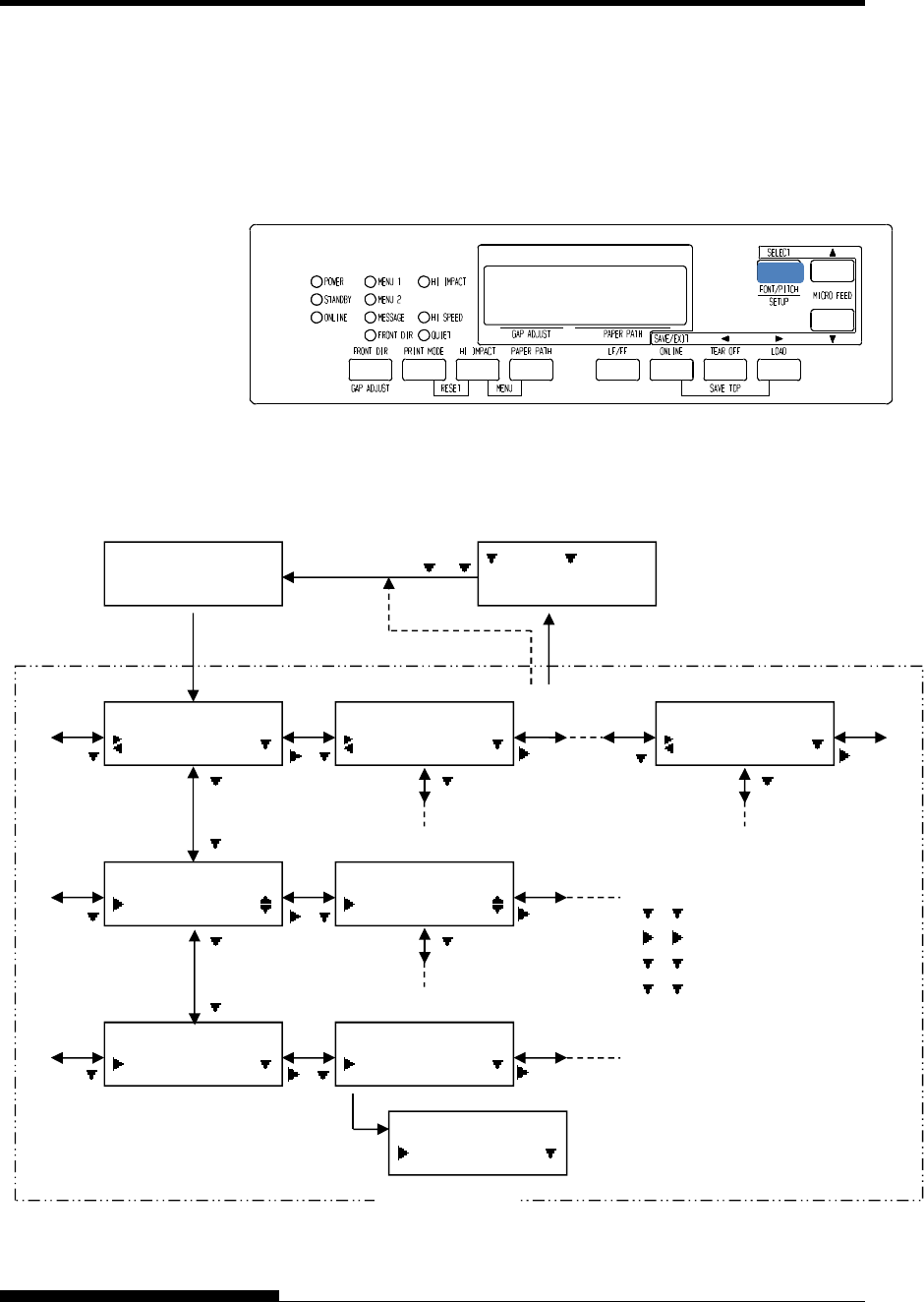
USING SETUP MODE
5-10 User's Manual
Printout of factory defaults using LIST
To enter setup mode, follow these steps:
1. Press the ONLINE button to place the printer offline.
2. Press the SETUP button until the printer beeps.
Entering setup mode
3. When the printer enters offline setup mode, LCD display shall
change as follows.
ENTERING SETUP
MODE(LCD)
OFFLINE
AUTO TRACTOR F
SETUP MODE
MENU1
SETUP MODE
MENU2
SETUP MODE
SELFDIAGNOSTIC
MENU1
EMULATE
EMULATE
*DPL24C+
:SAVE :CANCEL
MENU1
FONT
EMULATE
XL24E
EMULATE
*XL24E
SELECT button
SETUP button SAVE/EXIT button
SETUP MEN
U
“*” is applied to a selected option.
or
explanatory note
: button
: button
: button
: button
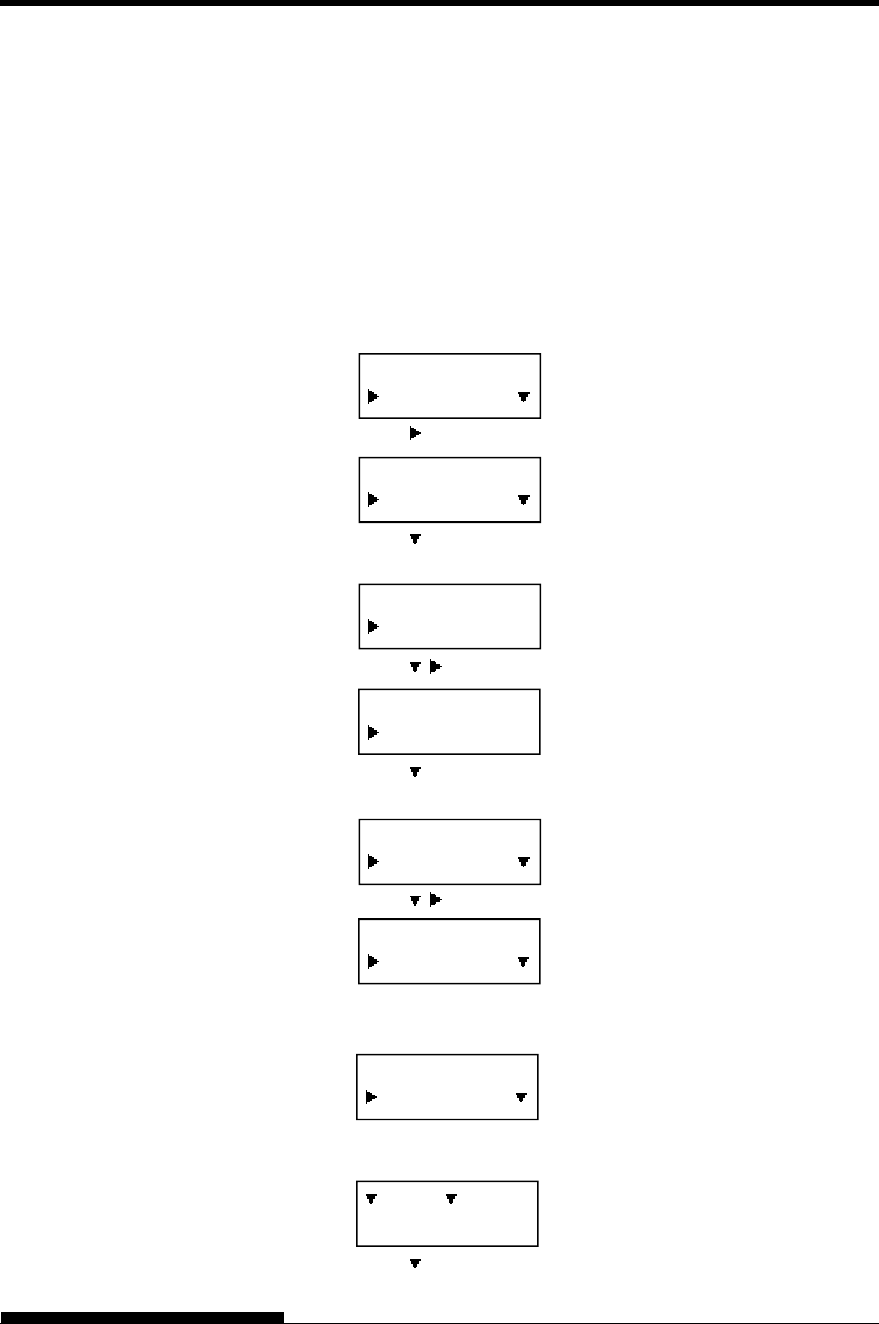
USING SETUP MODE
User's Manual 5-11
Transition of LCD SETUP MODE
Setup Mode Example (LCD)
To become familiar with setup mode, try the following example. This
example shows how to change the Emulation in MENU2 to ESC/P2.
1. Press the ONLINE button to place the printer online.
2. Press the SETUP button to enter select menu. Then following
message is displayed.
3. Press button until following message is displayed.
4. Press buttons to move to lower layer. Then following
message is displayed.
5. Press , to choose Items in this layer.
6. Press buttons to move to lower layer. Then following
message is displayed.
7. Press , to choose Options in this Item.
8. Press SELECT button to select displayed option. Then “*” is
applied to a selected option (not saved yet).
7. Press SAVE/EXIT buttons to register selected option on
printer’s permanent memory.
6. Press to finish.
SETUP MODE
MENU1
SETUP MODE
MENU2
MENU2
EMULATE
MENU2
EMULATE
EMULATE
*DPL24C+
EMULATE
ESC/P2
EMULATE
*ESC/P2
:SAVE :CANCEL
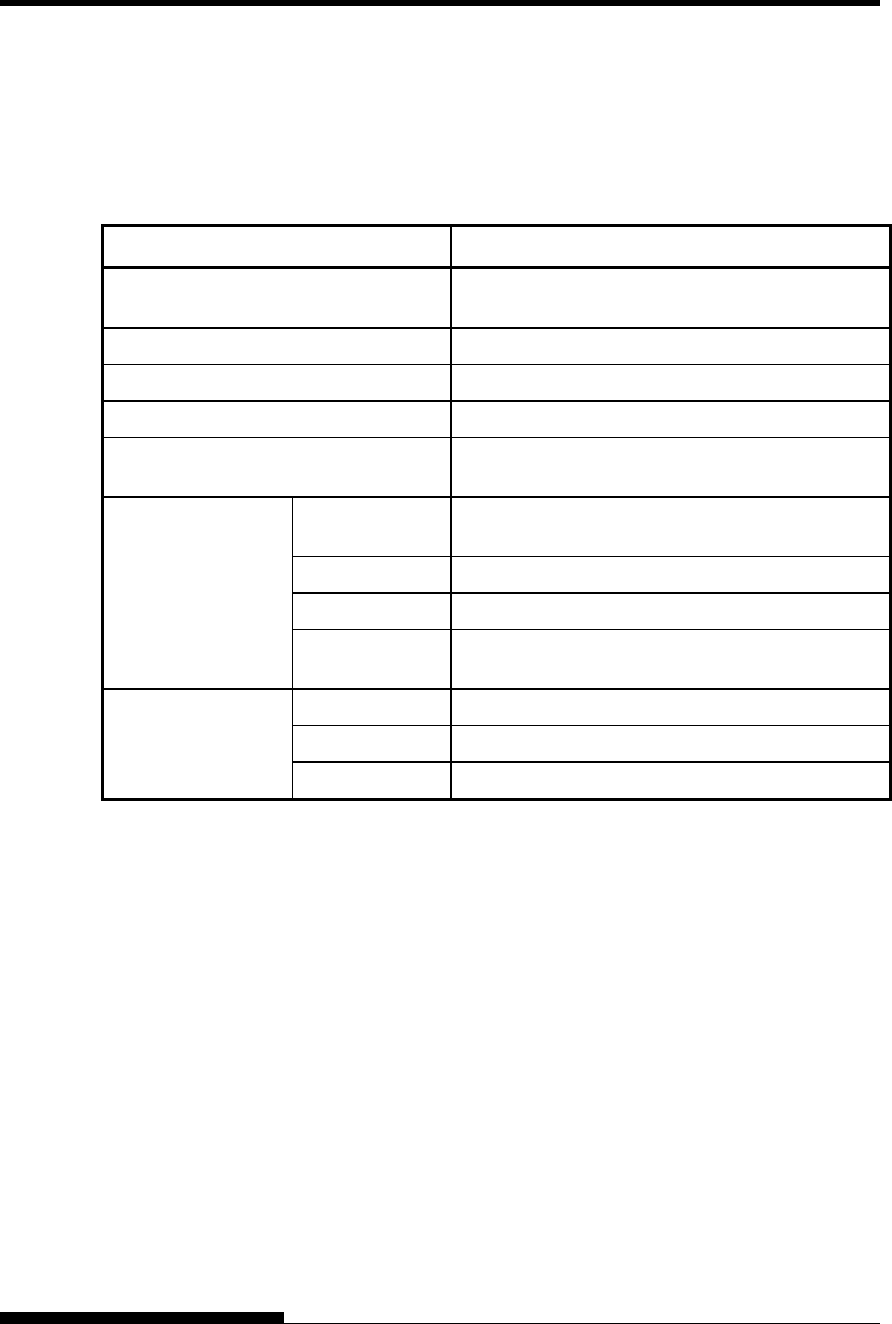
USING SETUP MODE
5-12 User's Manual
Available functions of LCD types SETUP MODE are as follows.
Table 5.2 summarizes the purpose of each function.
Table 5.2 Setup Mode Functions(LCD)
Function Purpose
MENU1 and MENU2 Assigns print features to MENU1 and MENU2 on
the printer control panel.
HARDWRE Changes the printer hardware options.
ADJUST Changes the print position adjustment options.
CONFIG Changes the configuration options.
GAP-ADJ Adjust the gap between the print head and printing
paper.
SUB FUNCTION SAVE&EXIT Exits setup mode and saves any changes made
while in setup mode.
LIST Prints a list of all currently selected options.
DEFAULT Resets factory defaults in MENU1 and MENU2.
INITIAL Resets factory defaults in MENU1, MENU2,
HARDWRE, ADJUST, CONFIG, GAP-ADJ.
SELFDIAGNOSTIC SELF-TST Runs the self-test.
HEX-DUMP Prints hex dumps.
V-ALMNT Checks and corrects vertical print alignment.
Detail of selecting items and options are almost same as LED type.
General difference of LCD type SETUP MODE is only SETUP method.
The LIST function prints a list of all the printer’s currently selected
options. This function is useful for checking the printer settings when
you first enter setup mode or just before you exit. To print a list of
options, load paper A4 size or more in advance and select list function.
NOTE
If paper runs out only LOAD button is available.
OVERVIEW OF
SETUP MODE (LCD)
PRINTING
A
LIST OF
SELECTED
OPTIONS(LCD)
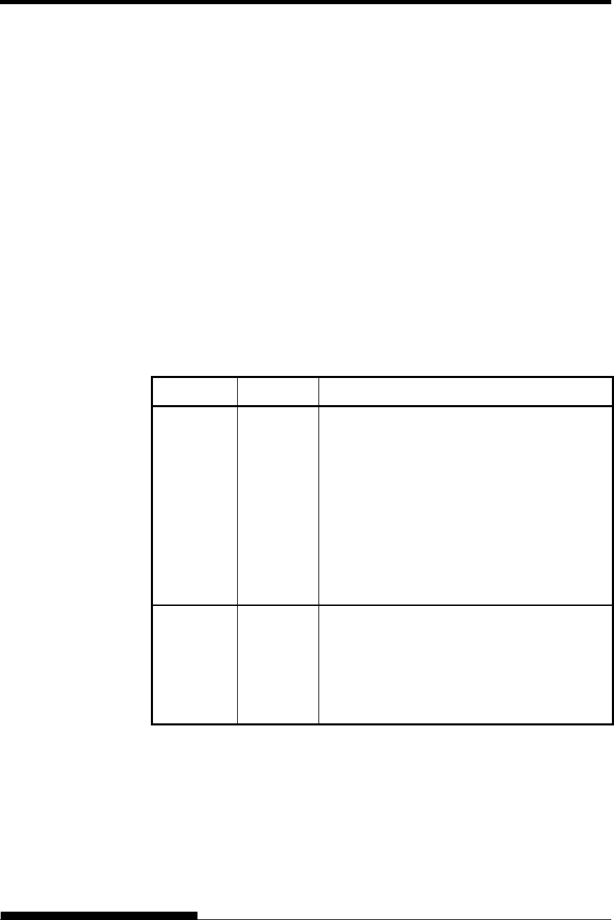
USING SETUP MODE
User's Manual 5-13
The previous page shows a printout of the printer’s factory default
settings. In this printout, options are listed by functional group:
Menu 1 settings (MENU1 function)
Menu 2 settings (MENU2 function)
Hardware settings (HARDWRE function)
Print position adjustment settings (ADJUST function)
Configuration settings (CONFIG function)
Print head gap adjustment settings (GAP-ADJ function)
Most selectable options only alter print features, such as the typestyle,
and page format. However, some options must be selected correctly for
the printer to work properly with your hardware and software.
For each function, Table 5.3 lists items whose options must be selected
correctly for system and printer accessory compatibility.
Table 5.3 Required Options
Function Item Option
MENU1 EMULATE The emulation selected on the printer must be the
same as the emulation selected in your software.
If you selected an emulation when you set up the
printer (Chapter 2), you do not need to change the
EMULATE option unless you want to change to
a different emulation. The emulation assigned to
MENU1 is the default when you turn the printer
on.
See the section MENU1 and MENU2 Items and
Options later in this chapter.
MENU2 None If you use MENU2, the emulation selected for
MENU 2 must be the same as the emulation
selected in your software.
See the section MENU1 and MENU2 Items and
Options later in this chapter.
DECIDING WHICH
OPTIONS TO
CHANGE
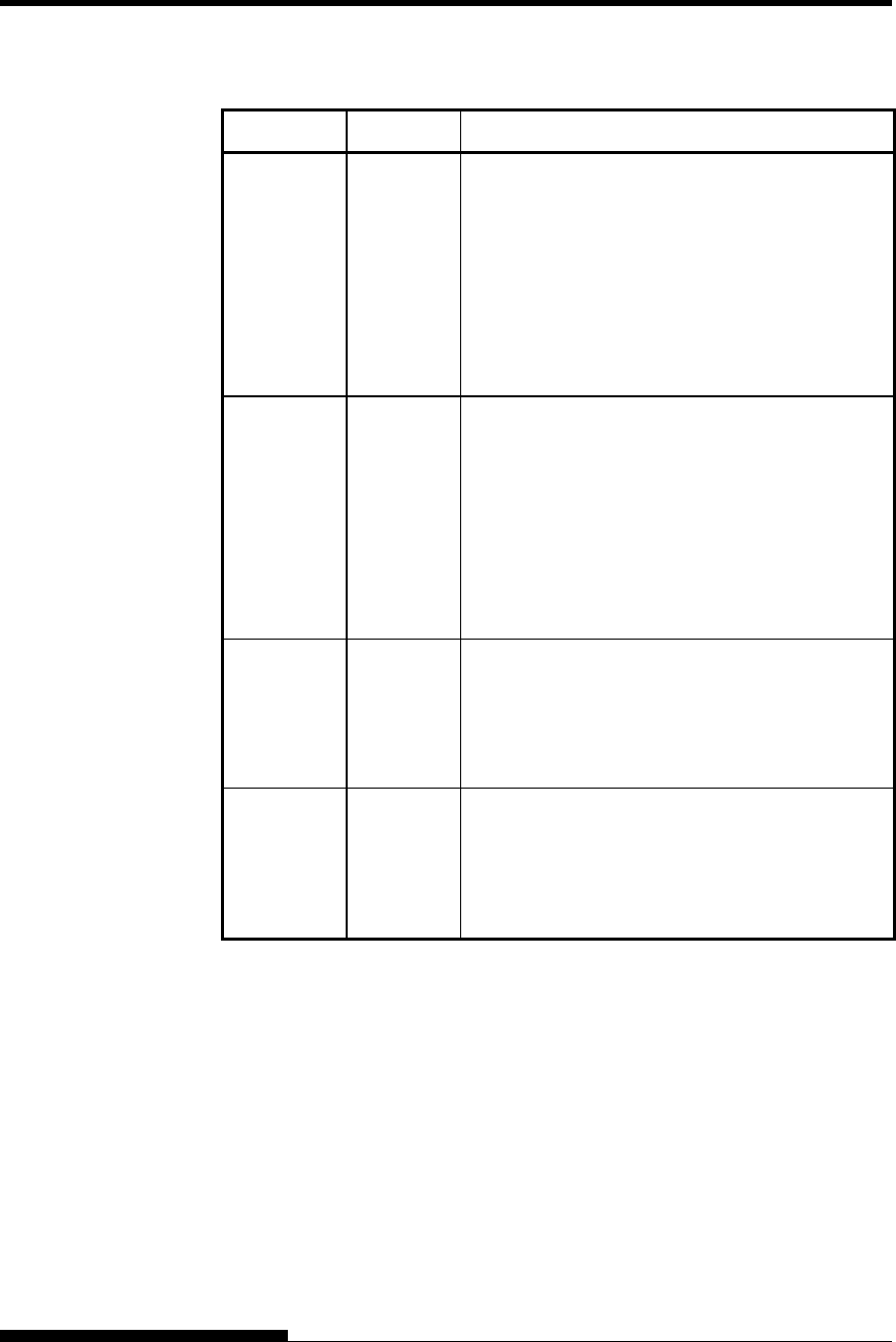
USING SETUP MODE
5-14 User's Manual
Table 5.3 Required Options (Cont.)
Function Item Option
HARDWRE FORMAT
BAUD-RT
PROTOCL
DSR
DUPLEX
CTS
CD
If you have a serial interface, the serial interface
options selected on the printer must be the same
as the settings you selected using your software or
your computer operating system. If the settings
are not the same, the printer will not print or will
print garbage.
See the section Hardware Items and Options
later in this chapter.
ADJUST None If you are not using software to specify the top
margin of the page, use the printer’s default top-
of-form setting, 1 inch (25.4 mm) from the top of
the paper. If you are using software to specify the
top margin of the page, change the default setting
to 1/6 inch (4.2 mm).
See the section Print Position Adjustment Items
and Options later in this chapter.
CONFIG None You can change the printer’s primary
configuration.
See the section Configuration Items and
Options later in this chapter.
GAP-ADJ None If you adjust the gap manually or fix the gap,
change the setting.
See the section Print Head Gap Adjustment
Items and Options.

USING SETUP MODE
User's Manual 5-15
The MENU1 and MENU2 functions allow you to change the print
options assigned to MENU1 and MENU2 on the printer control panel. In
normal (non-setup) mode, you can easily switch between the menus for
printing, as described in Chapter 4.
MENU1 is invoked when you first turn the printer on.
Select the same emulation on the printer as is selected in your software.
If the emulations are not the same, the printer will not work correctly
with your software. If you plan to use two different emulations on a
regular basis, assign the most frequently used emulation to MENU1.
Assign the second emulation to MENU2. All of the other settings
available for MENU1 and MENU2 are optional. Some of the items and
options will vary with the emulation.
To determine which features your software supports, refer to your
software documentation.
Table 5.4 describes the MENU1 and MENU2 items and options. Both
functions offer the same items and options. The items in Table 5.4 are
listed in the order in which they are printed. Not all items are defined for
all emulations and some options vary with the emulation.
The procedure for changing the options is referred to in the section Setup
Mode Example.
MENU1 AND MENU2
ITEMS AND
OPTIONS
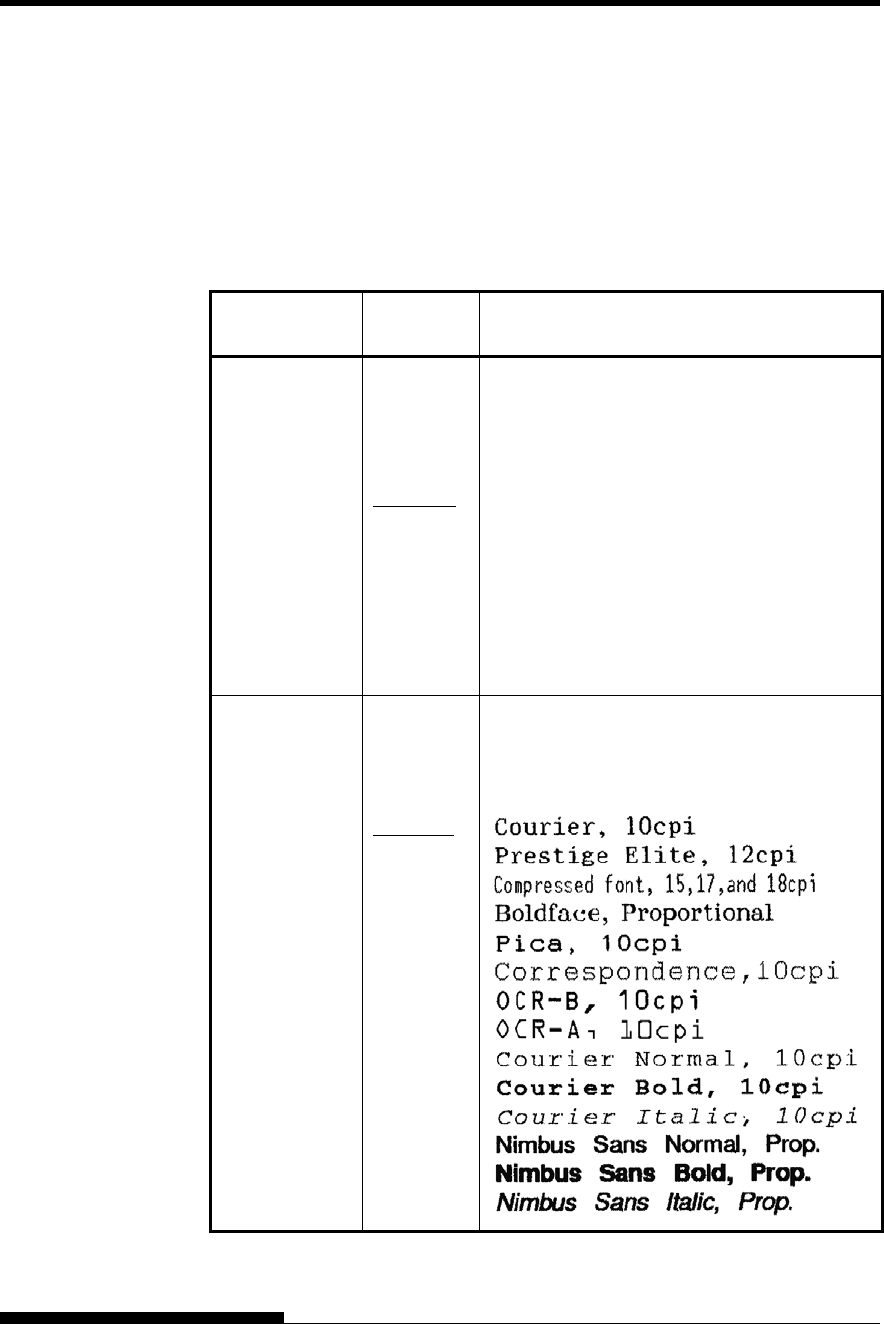
USING SETUP MODE
5-16 User's Manual
Table 5.4 MENU1 and MENU2 Items and Options
NOTES:
Underlined options are the factory defaults.
Asterisks identify items and options that differ for the IBM XL24E
and Epson ESC/P2 emulations. The notes are defined at the end of
the table.
MENU1 and
MENU2 Items Options Description
<EMULATE> Select the same emulation as is selected in your
software. See the section Selecting an
Emulation in Chapter 2 for information on
selecting an emulation.
DPL24C+ Fujitsu DL-series printers
(DPL24C PLUS command set)
XL24E
ESC/P2
IBM Proprinter XL24E printers Epson printers
using the ESC/P2 command set
NOTE: When you change the emulation, all
MENU1 or MENU2 options are reset to the
factory defaults for that emulation.
<FONT>
COUR 10
PRSTG12
COMPRSD
BOLDFCE
PICA 10
CORRESP
OCR-B
OCR-A
COUR-N
COUR-B
COUR-I
N.SAN-N
N.SAN-B
N.SAN-I
For each of the following fonts, the
recommended pitch settings are given after the
font name. When you change the font, be sure
to also change the pitch, if required.
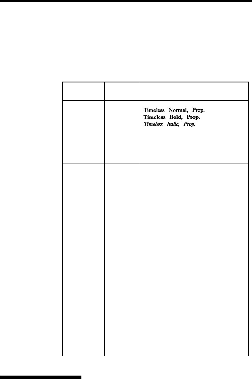
USING SETUP MODE
User's Manual 5-17
Table 5.4 MENU1 and MENU2 Items and Options (Cont.)
NOTES:
Underlined options are the factory defaults.
Asterisks identify items and options that differ for the IBM XL24E
and Epson ESC/P2 emulations. The notes are defined at the end of
the table.
MENU1 and
MENU2 Items Options Description
<FONT>
(continued)
TIMLS-N
TIMLS-B
TIMLS-I
DOWNLD# Font 0 or font 1 in the printer’s download
RAM
See Appendix F for font examples.
<QUALITY> Select the print quality that most often meets
your needs.
LETTER Letter print quality. This option provides the
highest resolution but the slowest print
speed. It cannot be used with the
compressed font.
REPORT Report print quality. This option provides
lower resolution than letter quality, but at
twice the speed. If you want only the double
speed, regardless of fonts, use the
correspondence font. The quality of the
correspondence font is higher than that of
report.
DRAFT Regular draft print quality. This option
provides lower resolution than report
quality, but at 3 times letter speed.
HI-DRFT High-speed draft print quality. This option
provides lower resolution than draft quality,
but at 4 times letter speed.
SH-DRFT
Super high-speed draft print quality. This
option provides lower resolution than hi-
draft quality, but at 4.4 times letter speed.
Condition: The margin is enough to speed
up.
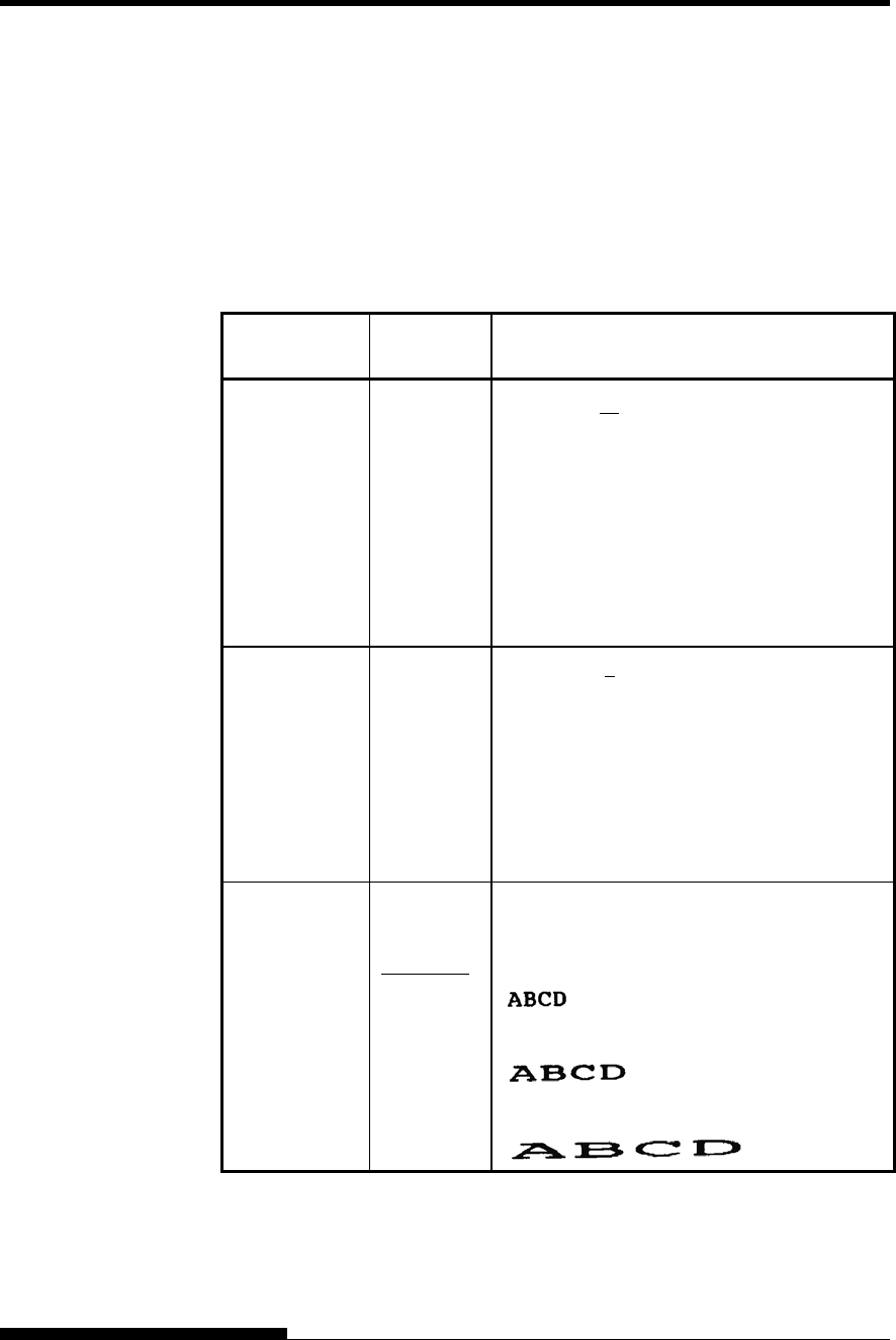
USING SETUP MODE
5-18 User's Manual
Table 5.4 MENU1 and MENU2 Items and Options (Cont.)
NOTES:
Underlined options are the factory defaults.
Asterisks identify items and options that differ for the IBM XL24E
and Epson ESC/P2 emulations. The notes are defined at the end of
the table.
MENU1 and
MENU2 Items Options Description
<PITCH> ## CPI 2.5, 3, 5, 6, 10, 12, 15, 17, 18, or 20 cpi
(characters per horizontal inch)
If 15cpi is selected at ESC/P2 emulation, font
size is compressed and DQ and HDQ printing
is done at LQ speed.
To avoid speed down, select NOCMPRS at
15CPI item.
PROP SP Proportional spacing (1/12 inch per character
space)
<LINE SP> ## LPI 1, 2, 3, 4, 5, 6, 7, or 8 lpi
(lines per vertical inch)
6 lpi 3 lpi (double spacing)
ABCD ABCD
ABCD
ABCD ABCD
ABCD
ABCD ABCD
ABCD
<CHAR-W> Change also the pitch 2 TIMES or 4 TIMES is
selected.
NORMAL Standard character width
2 TIMES Double character width
4 TIMES
(*1)
Quadruple character width
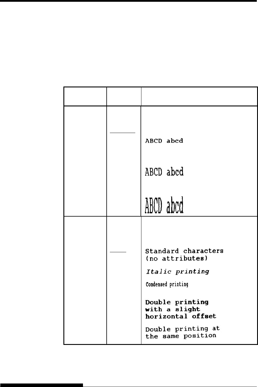
USING SETUP MODE
User's Manual 5-19
Table 5.4 MENU1 and MENU2 Items and Options (Cont.)
NOTES:
Underlined options are the factory defaults.
Asterisks identify items and options that differ for the IBM XL24E
and Epson ESC/P2 emulations. The notes are defined at the end of
the table.
MENU1 and
MENU2 Items Options Description
<CHAR-H> Change also the line spacing if 2 TIMES or 4
TIMES is selected.
NORMAL Standard character height
2 TIMES Double character height
4 TIMES
(*1)
Quadruple character height
<ATTRIB> Selects an attribute to add emphasis to your
documents.
Only one attribute may be selected at a time.
NONE
ITALICS
CONDNSD
(*1)
SHADOW
BOLD
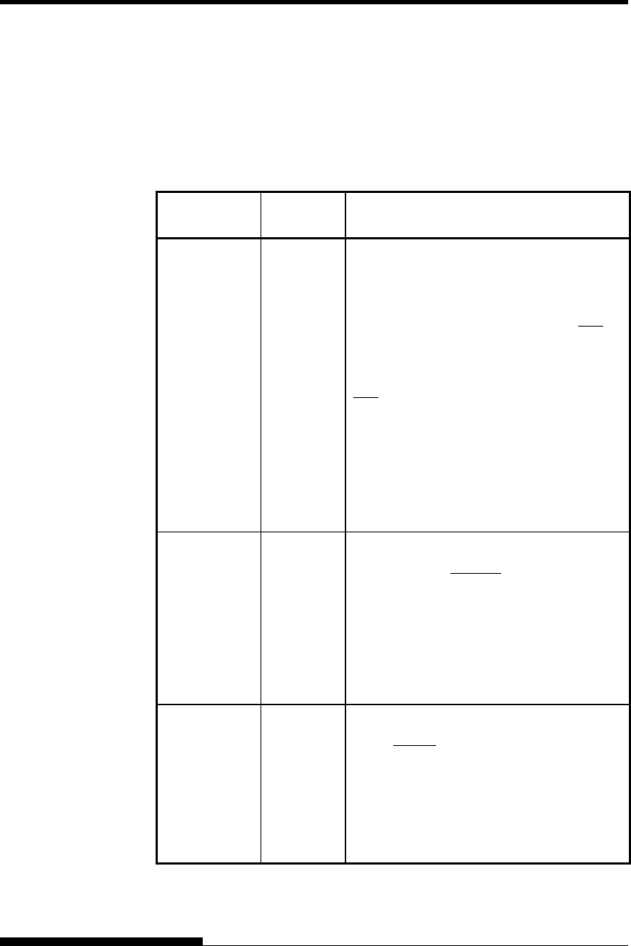
USING SETUP MODE
5-20 User's Manual
Table 5.4 MENU1 and MENU2 Items and Options (Cont.)
NOTES:
Underlined options are the factory defaults.
Asterisks identify items and options that differ for the IBM XL24E
and Epson ESC/P2 emulations. The notes are defined at the end of
the table.
MENU1 and
MENU2 Items Options Description
<PAGE LG> Specifies the length of the page in inches.
## IN For DPL24C PLUS and IBM XL24E
emulations:
3.0, 3.5, 4.0, 5.0, 5.5, 6.0, 7.0, 8.0, 8.5, 11.0
(letter size), 11.6 (A4 size), 12.0, 14.0, 18.0
inches, or LINE
For Epson ESC/P2 emulation: 4.0, 4.5, 5.0, ...,
11.0, 11.5, ..., 22.0 inches
LINE Selecting the page length by specifying
number of lines per page (default: 66 lines per
page) Selecting this option displays the <PG
LX10> and <PG LX1>. Use in combination
the <PG LX10> to set the tens value of the
lines-per-page setting, and the <PG LX1> to
set the ones value of the lines-per-page setting.
<PG LX10> Tens value
setting for
setting
number of
lines per
page
0 LINE, 10 LINE, 20 LINE, 30 LINE 40
LINE, 50 LINE, 60 LINE, 70 LINE 80 LINE,
90 LINE
The LINE setting depends on the line
spacing setting 'LINE SP'.
When 0 LINE is set, the line spacing
value is 11.0 IN (only when both 'PG
LX10' = '0 LINE' and 'PG LX1' = '0
LINE' are set).
<PG LX1> Ones value
setting for
setting
number of
lines per
page
0 LINE, 1 LINE, 2 LINE, 3 LINE 4 LINE, 5
LINE, 6 LINE, 7 LINE 8 LINE, 9 LINE
The LINE setting depends on the line
spacing setting 'LINE SP'.
When 0 LINE is set, the line spacing
value is 11.0 IN (only when both 'PG
LX10' = '0 LINE' and 'PG LX1' = '0
LINE' are set).
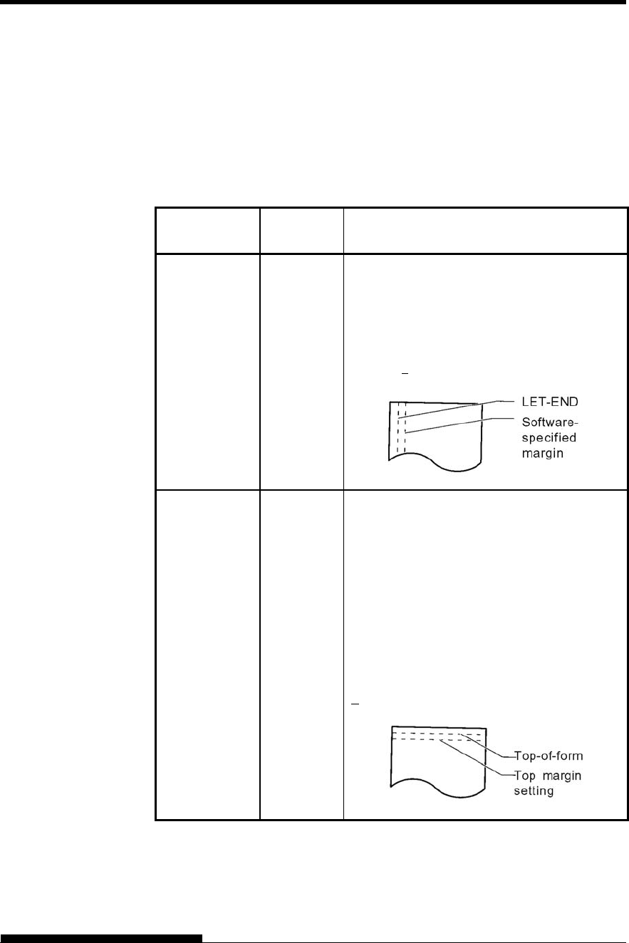
USING SETUP MODE
User's Manual 5-21
Table 5.4 MENU1 and MENU2 Items and Options (Cont.)
NOTES:
Underlined options are the factory defaults.
Asterisks identify items and options that differ for the IBM XL24E
and Epson ESC/P2 emulations. The notes are defined at the end of
the table.
MENU1 and
MENU2 Items Options Description
<LFT-END> Specifies the print start column for changing
the left margin. Printing starts at the position
given by this column plus your software-
specified left margin.
## COLM Column 1, 2, 3, ..., 41
<TOP-MRG> Specifies the number of space lines for the top
margin. The resultant blank space is the
<TOP-MRG> setting minus 1 line.
The total size of your top margin is the above
resultant value plus the following two settings:
top-of-form (default = 1 inch) and the
software-specified top margin. If you are using
software to specify the top margin, use the
default (1 line) for <TOP-MRG>.
## LINE 1, 2, 3,4, 5, 6, 7, 8, 9, or 10 lines
USING SETUP MODE
5-22 User's Manual
Table 5.4 MENU1 and MENU2 Items and Options (Cont.)
NOTES:
Underlined options are the factory defaults.
Asterisks identify items and options that differ for the IBM XL24E
and Epson ESC/P2 emulations. The notes are defined at the end of
the table.
MENU1 and
MENU2 Items Options Description
<LANGUGE> Selects a language. Appendix E shows the
character sets for each language.
Two-pass means that diacritical marks are
printed separately from their letters and that
letters are printed without any reduction.
The first listing is common to all emulations.
Options specific to each emulation are
skipped. See the subsequent listings (*2)
and(*3).
USA American English
(Same as code page 437)
UK British English
GERMAN German
SWEDISH Swedish
PAGE437 Code page 437
PAGE850 Code page 850
PAGE860 Code page 860
PAGE863 Code page 863
PAGE865 Code page 865
ECMA94 ECMA 94
ISO8859 ISO 8859-1
PG852 Code page 852
PG852-T Code page 852 two-pass
PG855 Code page 855
PG866 Code page 866
HUNGARY Hungarian
HUNG-T Hungarian two-pass
USING SETUP MODE
User's Manual 5-23
Table 5.4 MENU1 and MENU2 Items and Options (Cont.)
NOTES:
Underlined options are the factory defaults.
Asterisks identify items and options that differ for the IBM XL24E
and Epson ESC/P2 emulations. The notes are defined at the end of
the table.
MENU1 and
MENU2 Items Options Description
<LANGUGE>
(continued)
SLOV Slovenian
SLOV-T Slovenian two-pass
POLISH Polish
POLSH-T Polish two-pass
MAZOWIA Mazowian
MAZOW-T Mazowian two-pass
LATIN2 Latin 2
LATIN2-T Latin 2 two-pass
KAMENIC Kamenicky
KAMEN-T Kamenicky two-pass
TURKY Turkish
TURKY-T Turkish two-pass
CYRILIC Cyrillic
IBM437 IBM 437
IBM851 IBM 851
ELOT928 ELOT 928
PG-DHN Code page DHN
LATIN-P Latin Polish
ISO-LTN ISO Latin
LITHUA1 Lithuanian1
LITHUA2 Lithuanian2
MIK
MACEDON Macedonian
PG-MAC
ELOT927
USING SETUP MODE
5-24 User's Manual
Table 5.4 MENU1 and MENU2 Items and Options (Cont.)
NOTES:
Underlined options are the factory defaults.
Asterisks identify items and options that differ for the IBM XL24E
and Epson ESC/P2 emulations. The notes are defined at the end of
the table.
MENU1 and
MENU2 Items Options Description
<LANGUGE>
(continued)
ABG
ABY
DEC GR
HBR-OLD
PG862
HBR-DEC
GREEK 11
ISO-TUK ISO Turkish
RUSCII
LATIN-9
WCP1250 Windows-1250
WCP1251 Windows-1251
WCP1252 Windows-1252
(*2)
FRENCH French
ITALIAN Italian
SPANISH Spanish
DANISH1 Danish I
DANISH2 Danish II
FINNISH Finnish
NORWEGN Norwegian
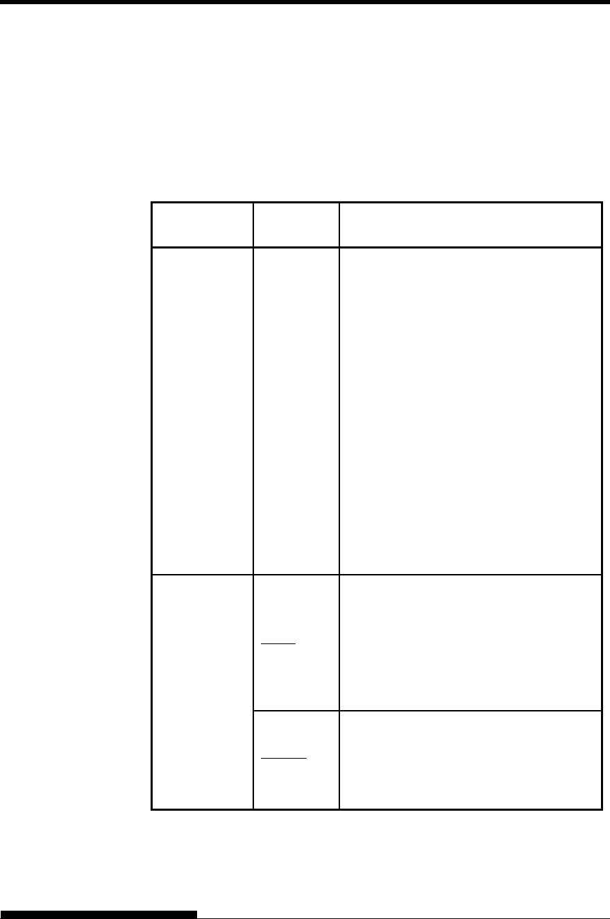
USING SETUP MODE
User's Manual 5-25
Table 5.4 MENU1 and MENU2 Items and Options (Cont.)
NOTES:
Underlined options are the factory defaults.
Asterisks identify items and options that differ for the IBM XL24E
and Epson ESC/P2 emulations. The notes are defined at the end of
the table.
MENU1 and
MENU2 Items Options Description
<LANGUGE>
(continued)
DANISH1 Danish I
ITALIAN Italian
SPANSH1 Spanish I
SPANSH2 Spanish II
JAPAN Japanese
NORWEGN Norwegian
LATIN A Latin American
FRENCH French
DANISH2 Danish II
KOREA Korea
LEGAL Legal
<CHR-SET> (*2)
SET 1
IBM character set 1
SET 2 IBM character set 2
If a downloaded (soft) font is used, the
character set for that font overrides the
<CHR-SET> setting.
(*3)
ITALIC Italic characters are available.
GRAPHIC Graphics characters (ruled lines) are
available.
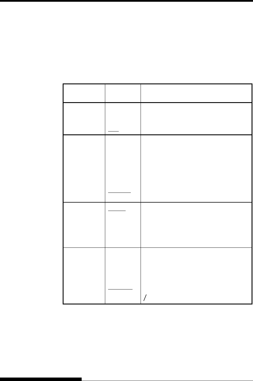
USING SETUP MODE
5-26 User's Manual
Table 5.4 MENU1 and MENU2 Items and Options (Cont.)
NOTES:
Underlined options are the factory defaults.
Asterisks identify items and options that differ for the IBM XL24E
and Epson ESC/P2 emulations. The notes are defined at the end of
the table.
MENU1 and
MENU2 Items Options Description
<AGM>
(*5)
ON Enables the graphic image command.
OFF Disables the graphic image command.
<PRF-SKP> For continuous forms, this option specifies
whether an inch is skipped around the
perforation. If you are not using software to
specify a bottom margin, select SKIP when
using thicker, multipart forms.
SKIP One inch is skipped around the perforation.
NO-SKIP The perforation is not skipped. Printing
continues in the bottom margin of the page.
<WIDTH> 13.6 IN 13.6-inch page width
11.4 IN 11.4-inch page width
11.0 IN 11-inch page width
8.0 IN 8-inch page width
<ZEROFNT> Specifies whether to print the number zero
with a slash. This is useful to distinguish the
capital letter “O” from the number “0”.
Invalid for some soft fonts.
NO-SLSH 0
SLASH 0
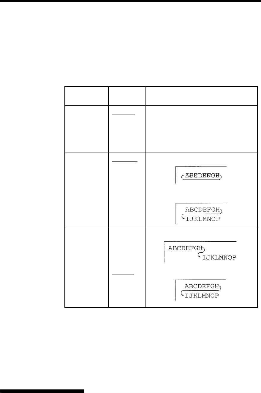
USING SETUP MODE
User's Manual 5-27
Table 5.4 MENU1 and MENU2 Items and Options (Cont.)
NOTES:
Underlined options are the factory defaults.
Asterisks identify items and options that differ for the IBM XL24E
and Epson ESC/P2 emulations. The notes are defined at the end of
the table.
MENU1 and
MENU2 Items Options Description
<DC3-CDE>
(*4)
ENABLE Enables the DC1 and DC3 codes.
Any data received between DC3 and the
next DC1 is ignored.
DISABLE Disables the DC1 and DC3 codes. These
codes are then ignored.
<CR-CODE> CR ONLY No line feed is added to a carriage return.
CR & LF A line feed is added to each carriage return.
<LF-CODE>
(*2)
LF ONLY No carriage return is added to a line feed.
LF & CR A carriage return is added to each line feed.
Note
The default value of <LF-CODE> changes with the selected emulations as
follows.
"LF&CR" is a default value in the DPL24C+ emulations.
"LF ONLY" is a default value in the XL24E emulations.
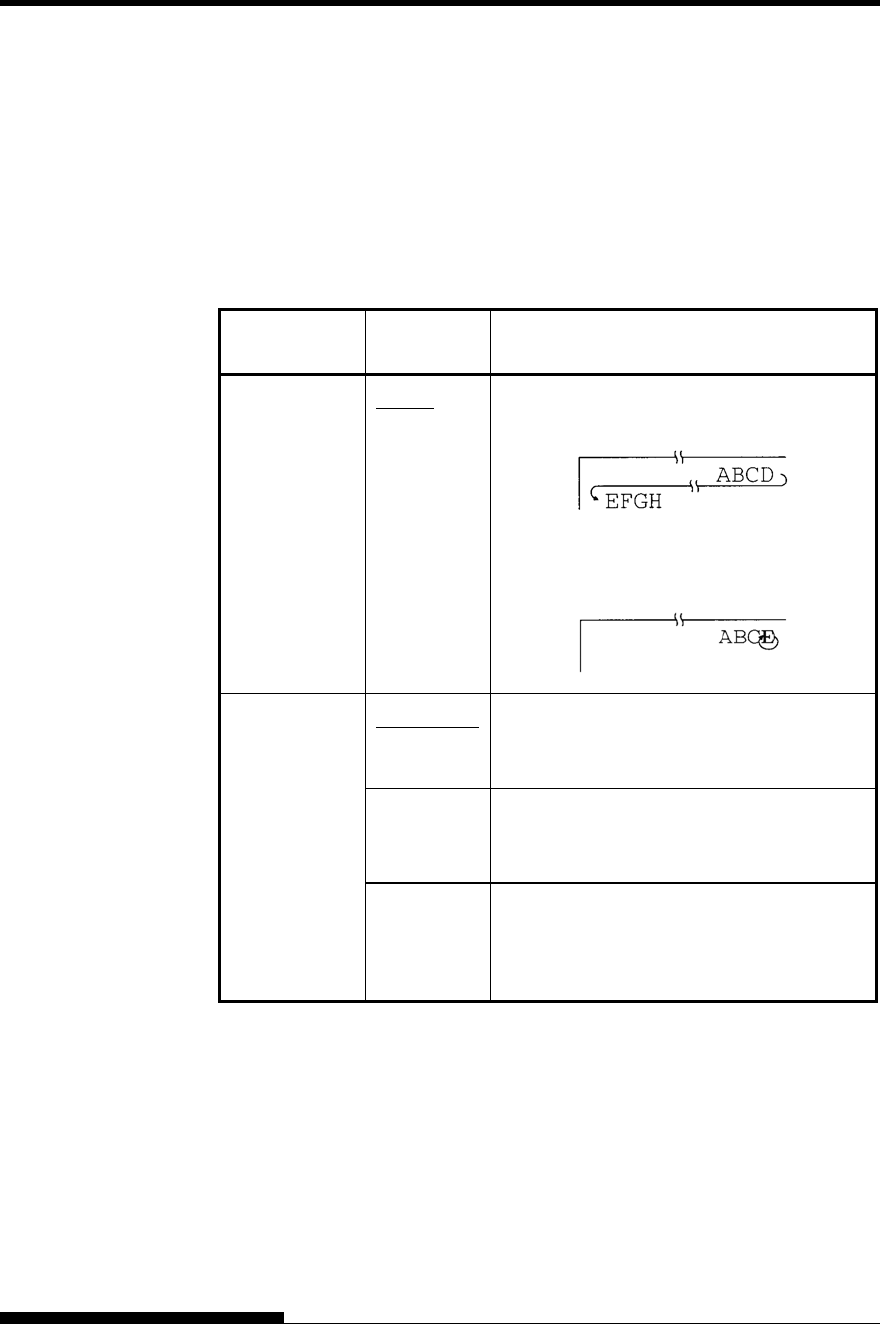
USING SETUP MODE
5-28 User's Manual
Table 5.4 MENU1 and MENU2 Items and Options (Cont.)
NOTES:
Underlined options are the factory defaults.
Asterisks identify items and options that differ for the IBM XL24E
and Epson ESC/P2 emulations. The notes are defined at the end of
the table.
MENU1 and
MENU2 Items Options Description
<RGHTEND> WRAP End-of-line wrap. Causes a carriage return
plus a line feed.
OVR-PRT Characters are overprinted at the end of a
line.
<15CPI> COMPRES1 Enables compression of font when 15cpi
selected at ESC/P2 emulation. Horizontal
and vertical font size is compressed.
COMPRS2 Enables compression of font when 15cpi
selected at ESC/P2 emulation. Horizontal
font size is compressed.
NOCMPRS Disables compression of font when 15cpi
selected at ESC/P2 emulation. When accept
the compressing command, only horizontal
compression is executed.
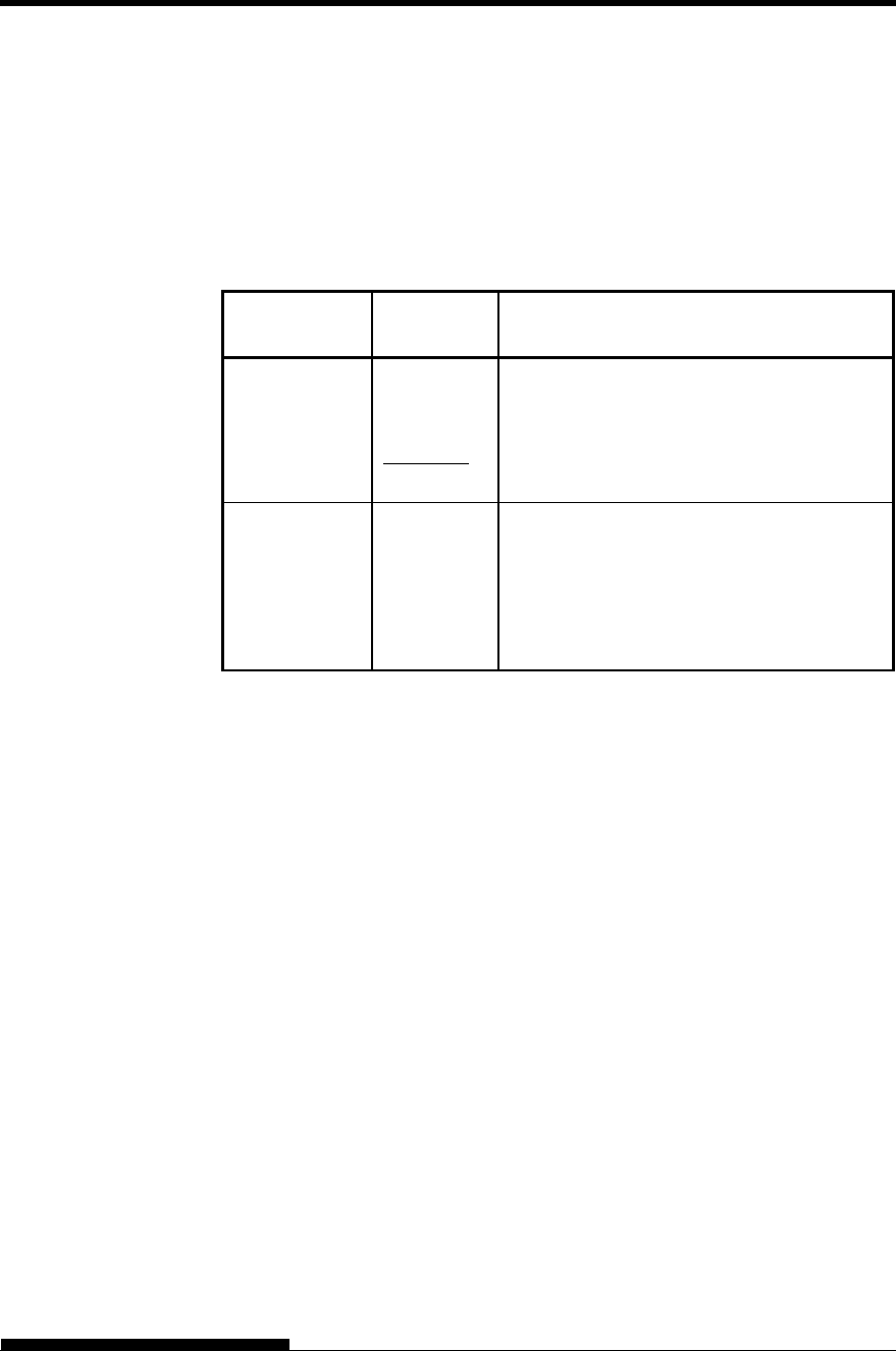
USING SETUP MODE
User's Manual 5-29
Table 5.4 MENU1 and MENU2 Items and Options (Cont.)
NOTES:
Underlined options are the factory defaults.
Asterisks identify items and options that differ for the IBM XL24E
and Epson ESC/P2 emulations. The notes are defined at the end of
the table.
MENU1 and
MENU2 Items Options Description
<INT-MEC> ENABLE Mechanical initial is operated by receiving a
reset command.
DISABLE Mechanical initial isn’t operated by receiving
a reset command.
<==END==> Indicates the end of MENU1 items. Press
the button to print the first item,
<EMULATE>. Press the button to print
the previous item, <INT-MEC>. Press the
ONLINE button to reprint the
<<FUNCTION>> menu.
*1 Unavailable in the IBM XL24E emulation
*2 Unavailable in the Epson ESC/P2 emulations
*3 Available only in the Epson ESC/P2 emulations
*4 Available only in the DPL24C+ emulation
*5 Available only in the IBM XL24E emulation
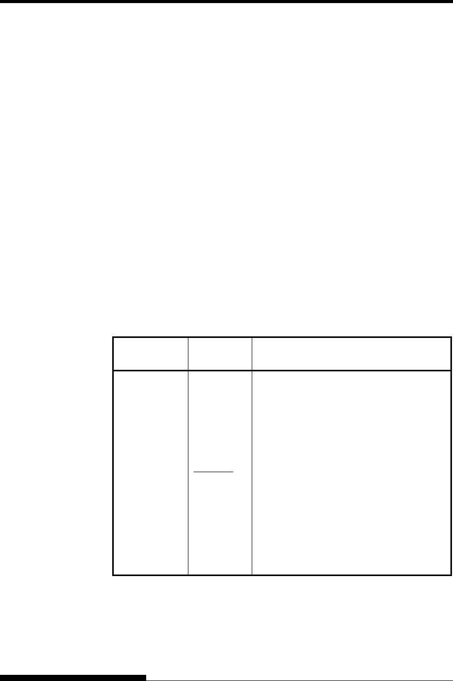
USING SETUP MODE
5-30 User's Manual
Resetting MENU1 and MENU2
To reset the factory defaults for both MENU1 and MENU2, select the
DEFAULT/INITIAL function. For more information, see the section
Resetting Defaults later in this chapter. The DEFAULT function cannot
reset those options which are handled by the HARDWRE, ADJUST,
CONFIG, and GAP-ADJ functions. The INITIAL function can reset
those options which are handled by the HARDWRE, ADJUST, CONFIG,
and GAP-ADJ functions.
The HARDWRE function defines the printer’s hardware operating
conditions. If you are using the optional RS-232C serial interface,
the serial interface options must be set properly for the printer to
function correctly with your system hardware.
Table 5.5 describes the HARDWRE items and options. Items are
listed in the order in which they are printed. The procedure for changing
the hardware options is described after Table 5.5.
Table 5.5 HARDWARE Items and Options
NOTE: Underlined options are the factory defaults.
HARDWARE
Items Options Description
<PPR-OUT> Specifies how the printer responds when you
run out of paper.
CNTONLY The printer detects paper-out only for
continuous forms. Printing stops and the
PAPER OUT indicator lights red.
DETECT The printer detects paper-out for both
continuous forms and single sheets. Printing
stops and the PAPER OUT indicator lights
red.
IGNORE The printer ignores paper-out for both
continuous forms and single sheets. Printing
continues until no more data remains. No
PAPER OUT warning is displayed.
CHANGING
HARDWARE
OPTIONS
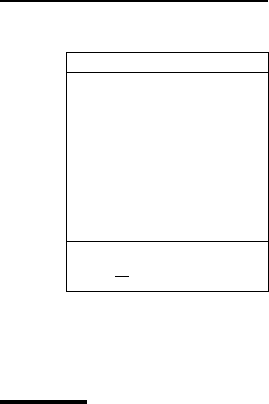
USING SETUP MODE
User's Manual 5-31
Table 5.5 HARDWARE Items and Options (Cont.)
NOTE: Underlined options are the factory defaults.
HARDWARE
Items Options Description
<PRT-DIR> BI-DIR Bidirectional printing. The printer prints in
either direction while seeking the next print
direction for a shorter print time.
UNI-DIR Unidirectional printing. Unidirectional
printing is used for printing vertical lines in
tables even if vertical alignment is not
adjusted. Unidirectional printing is slower
than bidirectional printing.
<BUZZER> Enables or disables the printer status buzzer.
ON Buzzer on (recommended).
The printer beeps to indicate paperout or
other conditions.
ON-1 Buzzer on (Low quality)
Sound in bass (Low frequency sound)
ON-2 Buzzer on (High-quality sound)
Sound in high-pitched tone (High frequency
sound)
OFF Buzzer off under any conditions.
<WORD-LG> To determine the required word length, refer
to your computer documentation. Select 8-
BIT to print bit image graphics.
8 BIT 8-bit word length (used by most computers)
7 BIT 7-bit word length (MSB = 0)
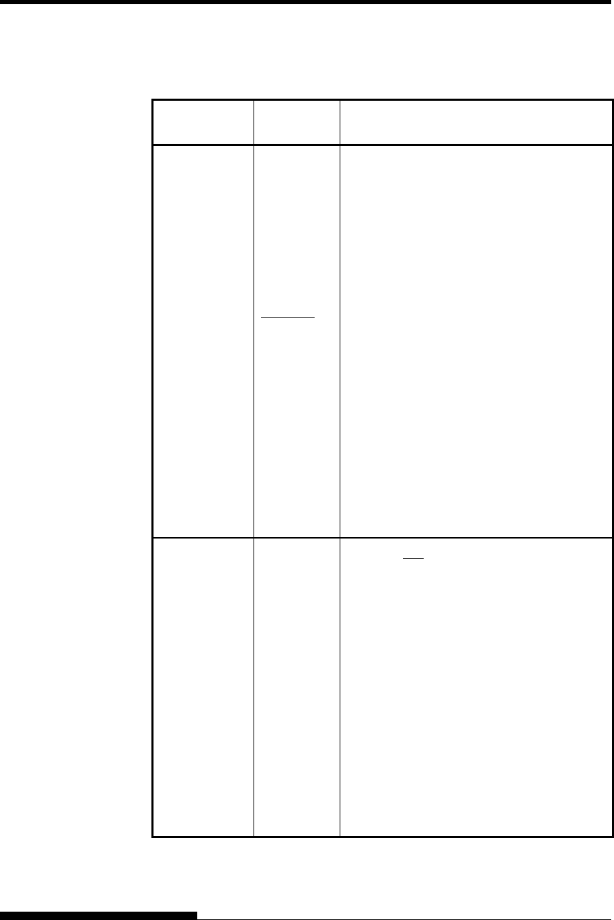
USING SETUP MODE
5-32 User's Manual
Table 5.5 HARDWAREItems and Options (Cont.)
NOTE: Underlined options are the factory defaults.
HARDWARE
Items Options Description
<BUFFER> Assigns buffer memory to input data and
downloaded font data.
Print buffer Download buffer
NONE 0 byte 128K bytes
256BYTE 256 bytes 127.75K bytes
2KBYTE 2K bytes 126K bytes
8KBYTE 8K bytes 120K bytes
24KBYTE 24K bytes 104K bytes
32KBYTE 32K bytes 96K bytes
96KBYTE 96K bytes 32K bytes
128KBYT 128K bytes 0K bytes
NOTE:
0BYTE option is recommended only
for graphics application.
With 128KB selected, the printer
cannot accept any download font data.
<SENLEVL> ## % 120, 110, 100, 90, 80, 70 or 60 %
The threshold level of Photo Sensor for Paper
Edge Detection.
If output voltage of photo sensor is not
enough, threshold level should be lower so
that sensor can detect paper properly.
In general reasons of low voltage of sensor
output are as follows.
・Paper color is too dark.
・Preprint is on scanning area.
Note
The margin for strong light from outside
would be decreased, if you select threshold
level lower than 100% (90,80,70 or 60%).
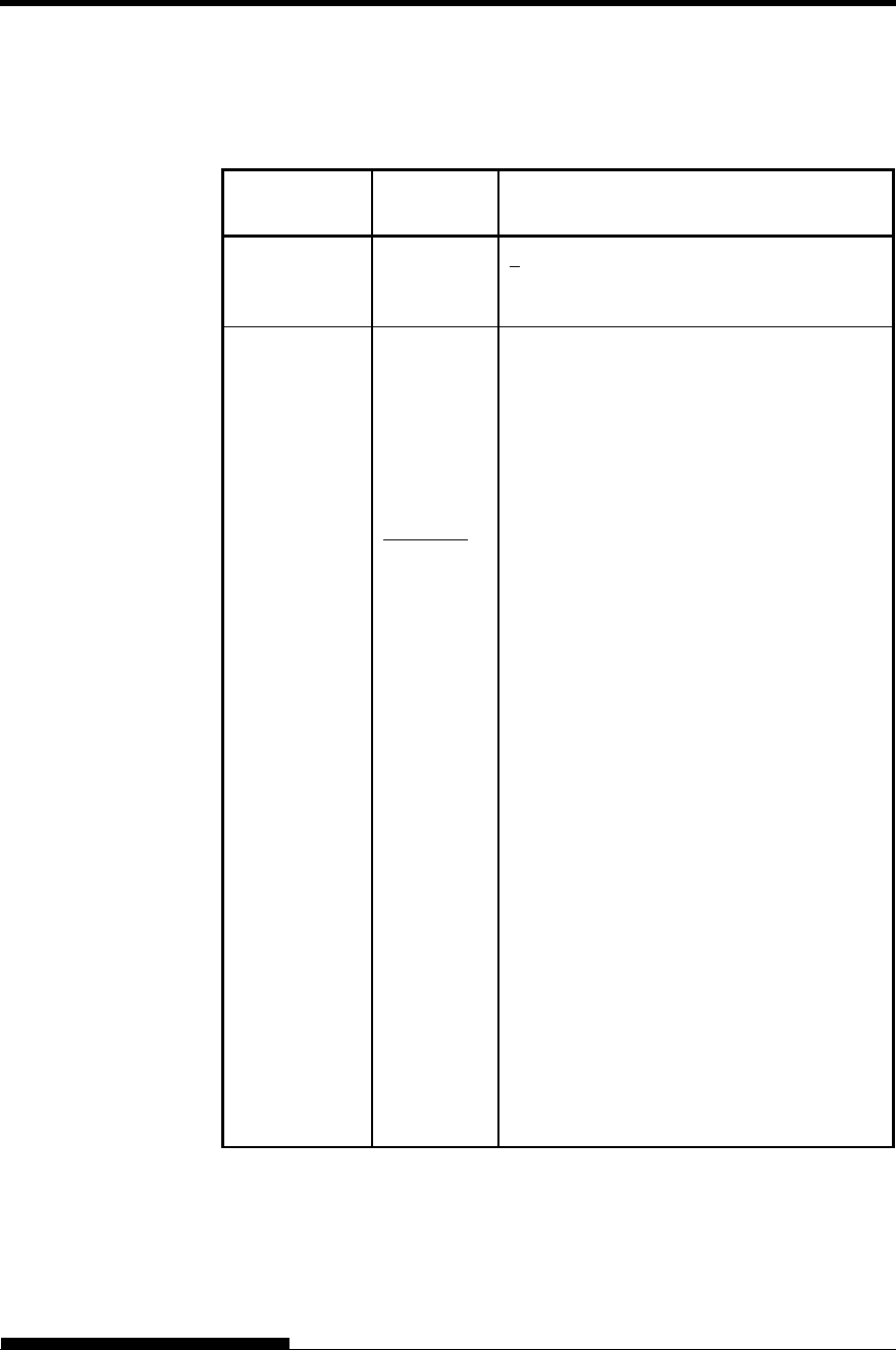
USING SETUP MODE
User's Manual 5-33
Table 5.5 HARDWARE Items and Options (Cont.)
NOTE: Underlined options are the factory defaults.
HARDWARE
Items Options Description
<STANDBY> ## MIN 1, 3, 5, 10, 20 or 30 MIN
Time until shifting to the power saving mode
is set.
<INTRFCE> Selects the type of the interface to the
computer.
PARALEL Centronics parallel interface
SERIAL RS-232C serial interface
USB USB interface
AUTO-2S Auto interface selection mode
AUTO-4S
AUTO-6S
Both interfaces are ready for
communication.
AUTO10S
AUTO15S
Specify the timing regarding the selected
interface as being inactive.
AUTO20S To switch the interface to the optional LAN
interface, mount the LAN card with the setup
mode set to “AUTO-XS” or “AUTOXXS”
under “INTERFCE,” which in turn is under
“HARDWRE” The interface will
automatically switch to the optional LAN
interface.
To switch the interface to something other
than the optional LAN interface, do either of
the following:
To return the setup mode to
“INTERFCE” under “HARDWRE,”
remove the LAN card.
To switch the interface to a fixed
interface, set PARALEL,USB with the
LAN card mounted, and the setup mode
set to “INTERFCE” under
“HARDWRE.”
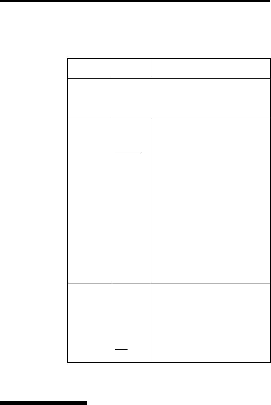
USING SETUP MODE
5-34 User's Manual
Table 5.5 HARDWARE Items and Options (Cont.)
NOTE: Underlined options are the factory defaults.
HARDWARE
Items Options Description
Serial Interface or USB interface Items. The following <FORMAT> to
<DUPLEX> items are not printed when you select the PARALEL option for
the <INTRFCE> item. Be sure that the options selected on the printer are the
same as the options selected using your computer operating system or your
software. Refer to the documentation provided for your computer and software.
<FORMAT> Number
of data
bits
Parity bit Number of stop
bits
8NONE 1 8 None 1
8NONE 2 8 None 2
8EVEN 1 8 Even 1
8ODD 1 8 Odd 1
7EVEN 1 7 Even 1
7ODD 1 7 Odd 1
7MARK 1 7 Mark 1
7SPACE 1 7 Space 1
7EVEN 2 7 Even 2
7ODD 2 7 Odd 2
The data format also includes a start bit. The
mark is logical 1. The space is logical 0.
<BAUD-RT> 150
300
600
1200
2400
4800
9600
19200
The baud rate is in bps (bits per second).
Select the same baud rate as 600 used by your
computer or modem.
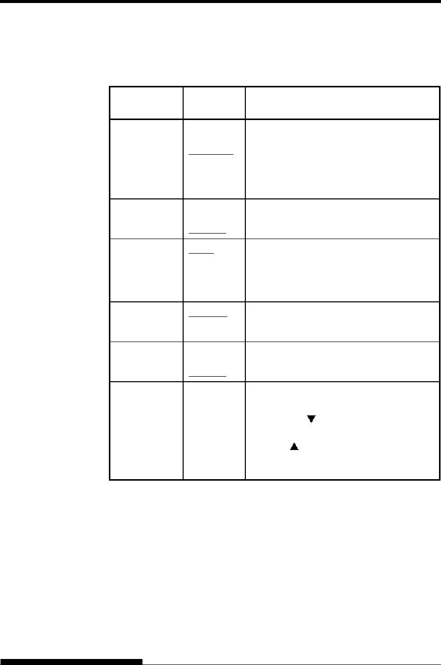
USING SETUP MODE
User's Manual 5-35
Table 5.5 HARDWARE Items and Options (Cont.)
NOTE: Underlined options are the factory defaults.
HARDWARE
Items Options Description
<PROTOCL> Indicates data transmission protocol.
XON/XOF The DC1 and DC3 codes are used.
DTR The Data Terminal Ready signal is used.
REV-CHL The Reverse Channel signal is used.
<DSR> DETECT DSR is detected by the printer.
IGNORE DSR is ignored by the printer.
<DUPLEX> FULL Simultaneous data transmission occurs in
opposite directions.
HALF Data transmission occurs in either direction,
but not simultaneously.
<CTS> DETECT CTS is detected by the printer.
IGNORE CTS is ignored by the printer.
<CD> DETECT CD is detected by the printer.
IGNORE CD is ignored by the printer.
<==END==> (LED only)
Indicates the end of the HARDWRE item
list. Press the button to print the first item,
which is <PPR-OUT>.
Press the button to print the previous
item. Press the ONLINE button to reprint the
<<FUNCTION>> menu.

USING SETUP MODE
5-36 User's Manual
When you print using ruled paper, you often want to adjust the print
position so that the print sits properly on the ruled lines. The ADJUST
function allow you to:
Set top-of-form position
Fine-tune top-of-form position
Fine-tune left print start column (left margin)
Adjust for accumulative line spacing error in a page
The top edge of your paper is the physical top of the page. The logical
top of the page, as “understood” by the printer when loading paper, is
called the top-of-form. Printing starts at this position. Note that printing
actually starts at the position obtained by adding the following:
Top-of-form, default = 1.8/6 inch (7.6mm)
Top margin specified by your software
Printer TOP-MRG (top margin setting), default = 1 line
Table 5.6 describes the ADJUST items and options. Items are listed in
the order they are printed. The procedure for changing top-of-form is
described after Table 5.6.
CHANGING PRINT
POSITION
ADJUSTMENT
OPTIONS
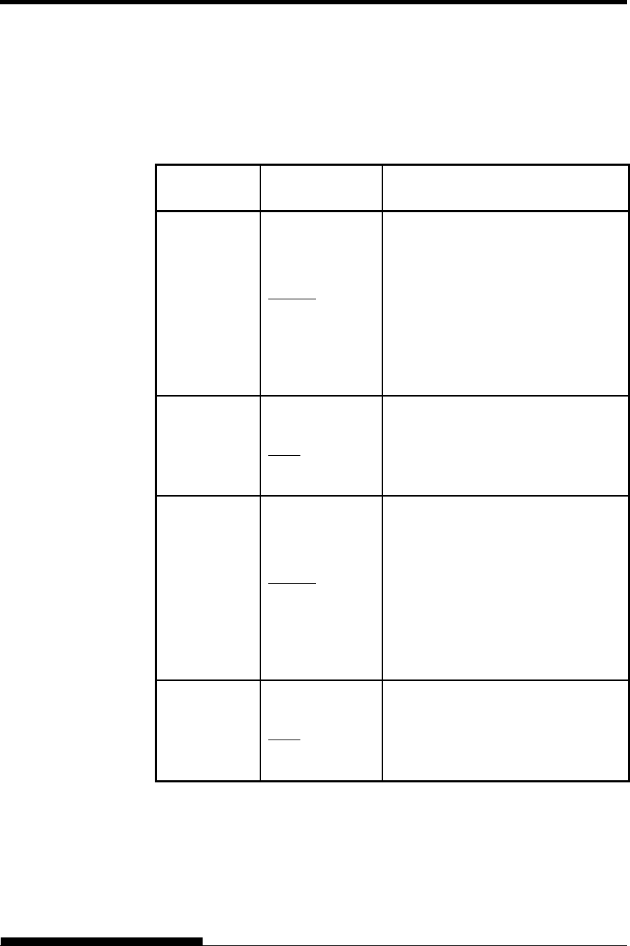
USING SETUP MODE
User's Manual 5-37
Table 5.6 ADJUST Items and Options
NOTE: The top of form position is out of paper at [-1/6 IN] and [0/6 IN].
When printing, set the margin more than 1/6inch.
ADJUST
Items Options Description
<FCNTORG> -1/6 IN
0/6 IN
1/6 IN
1.8/6 IN
:
6/6 IN
:
66/6 IN
Sets the top-of-form for front
continuous forms in increments of 1/6
inch (4.2 mm) from the physical top of
the page.
The default is recommended if your top
margin is not software-specified. A
setting of 1/6 inch is preferable when
your top margin is software-specified.
<FCNTFIN>
0/180, ..., 29/180
Fine-tunes the top-of-form position for
front continuous forms.
Increases top-of-form in increments of
1/180 inch
(0.14 mm).
<RCNTORG> -1/6 IN
0/6 IN
1/6 IN
1.8/6 IN
:
6/6 IN
:
66/6 IN
Sets the top-of-form for rear continuous
forms in increments of 1/6 inch (4.2
mm) from the physical top of the page.
The default is recommended if your top
margin is not software-specified. A
setting of 1/6 inch is preferable when
your top margin is software-specified.
<RCNTFIN>
0/180, ..., 29/180
Fine-tunes the top-of-form position for
rear continuous forms.
Increases top-of-form in increments of
1/180 inch
(0.14 mm).
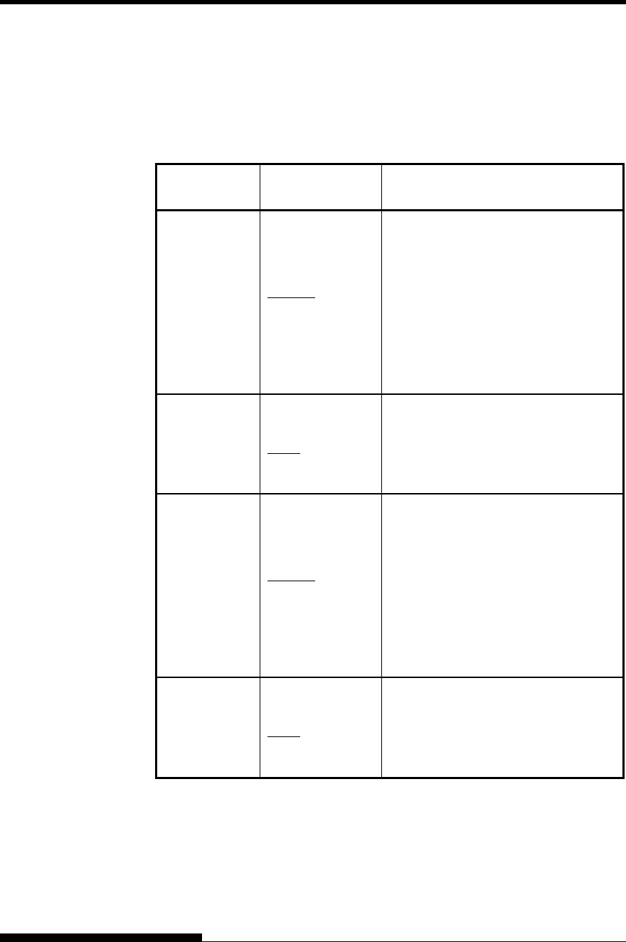
USING SETUP MODE
5-38 User's Manual
Table 5.6 ADJUST Items and Options (Cont.)
NOTE: The top of form position is out of paper at [-1/6 IN] and [0/6 IN].
When printing, set the margin more than 1/6inch.
ADJUST
Items Options Description
<FCUTORG> -1/6 IN
0/6 IN
1/6 IN
1.8/6 IN
:
6/6 IN
:
66/6 IN
Sets the top-of-form for front single
sheets in increments of 1/6 inch (4.2
mm) from the physical top of the page.
The default is recommended if your top
margin is not software-specified. A
setting of 1/6 inch is preferable when
your top margin is software-specified.
<FCUTFIN>
0/180, ..., 29/180
Fine-tunes the top-of-form position for
front single sheets.
Increases top-of-form in increments of
1/180 inch
(0.14 mm).
<RCUTORG> -1/6 IN
0/6 IN
1/6 IN
1.8/6 IN
:
6/6 IN
:
66/6 IN
Sets the top-of-form for rear single
sheets in increments of 1/6 inch (4.2
mm) from the physical top of the page.
The default is recommended if your top
margin is not software-specified. A
setting of 1/6 inch is preferable when
your top margin is software-specified.
<RCUTFIN>
0/180, ..., 29/180
Fine-tunes the top-of-form position for
rear single sheets.
Increases top-of-form in increments of
1/180 inch
(0.14 mm).
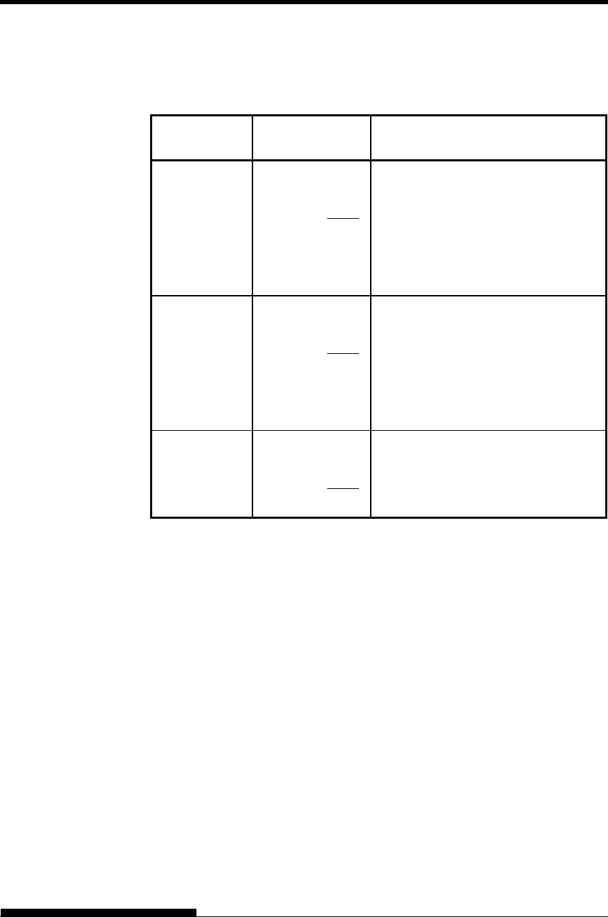
USING SETUP MODE
User's Manual 5-39
Table 5.6 ADJUST Items and Options (Cont.)
NOTE: Underlined options are the factory defaults.
ADJUST
Items Options Description
<FCNTBTM>
-30/180, ..., 0/180,
..., 30/180
It is possible to fine-tune the bottom
blank by every 1/180 inches for its
amount (4.2mm) of the front
continuous form.
NOTE:
This setting is effective only at <
FCNT-PE:EDGE >.
<RCNTBTM>
-30/180, ..., 0/180,
..., 30/180
It is possible to fine-tune the bottom
blank by every 1/180 inches for its
amount (4.2mm) of the back
continuous form.
NOTE:
This setting is effective only at <
FCNT-PE:EDGE >.
<CUT-BTM>
-30/180, ..., 0/180,
..., 30/180
It is possible to fine-tune the bottom
blank by every 1/180 inches for its
amount (4.2mm) of the cut sheet paper.
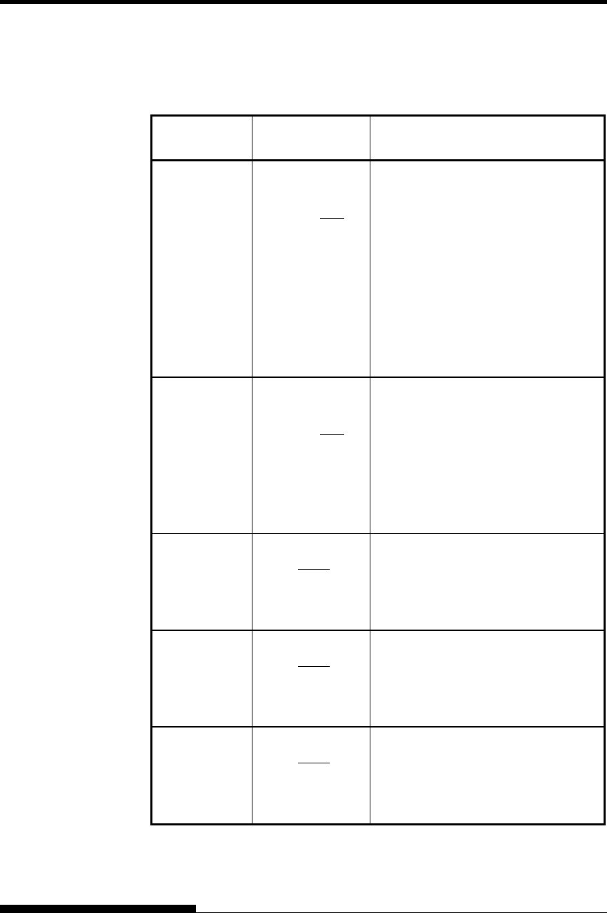
USING SETUP MODE
5-40 User's Manual
Table 5.6 ADJUST Items and Options (Cont.)
NOTE: Underlined options are the factory defaults.
ADJUST
Items Options Description
<CNT-LFT>
-10/90, ..., 0/90,
..., 10/90
Fine-tunes the left print start position
for continuous forms.
Moves the position left or right in
increments of 1/90 inch
(0.28 mm).
NOTE:
This setting is effective only at
< RCNT-SF: DISABLE > when the
back tractor is used.
< FCNT-SF: DISABLE > when the
front tractor is used.
<CUT-LFT>
-10/90, ..., 0/90,
..., 10/90
Fine-tunes the left print start position
for single sheets.
Moves the position left or right in
increments of 1/90 inch
(0.28 mm).
NOTE:
This setting is effective only at < CUT-
SF:DISABLE >.
<FCNTADJ> -14/360, -9/360, -
4/360, 0/360
4/360, 9/360,
14/360,
GRAPHIC(*1)
Compensates for the forms feed error
accumulated through feeding of front
continuous forms.
<RCNTADJ> -14/360, -9/360, -
4/360, 0/360
4/360, 9/360,
14/360,
GRAPHIC(*1)
Compensates for the forms feed error
accumulated through feeding of rear
continuous forms.
<FCNTAJL> -14/360, -9/360, -
4/360, 0/360
4/360, 9/360,
14/360,
GRAPHIC(*1)
Compensates for the forms feed error
accumulated through feeding of front
continuous forms. (Last page)
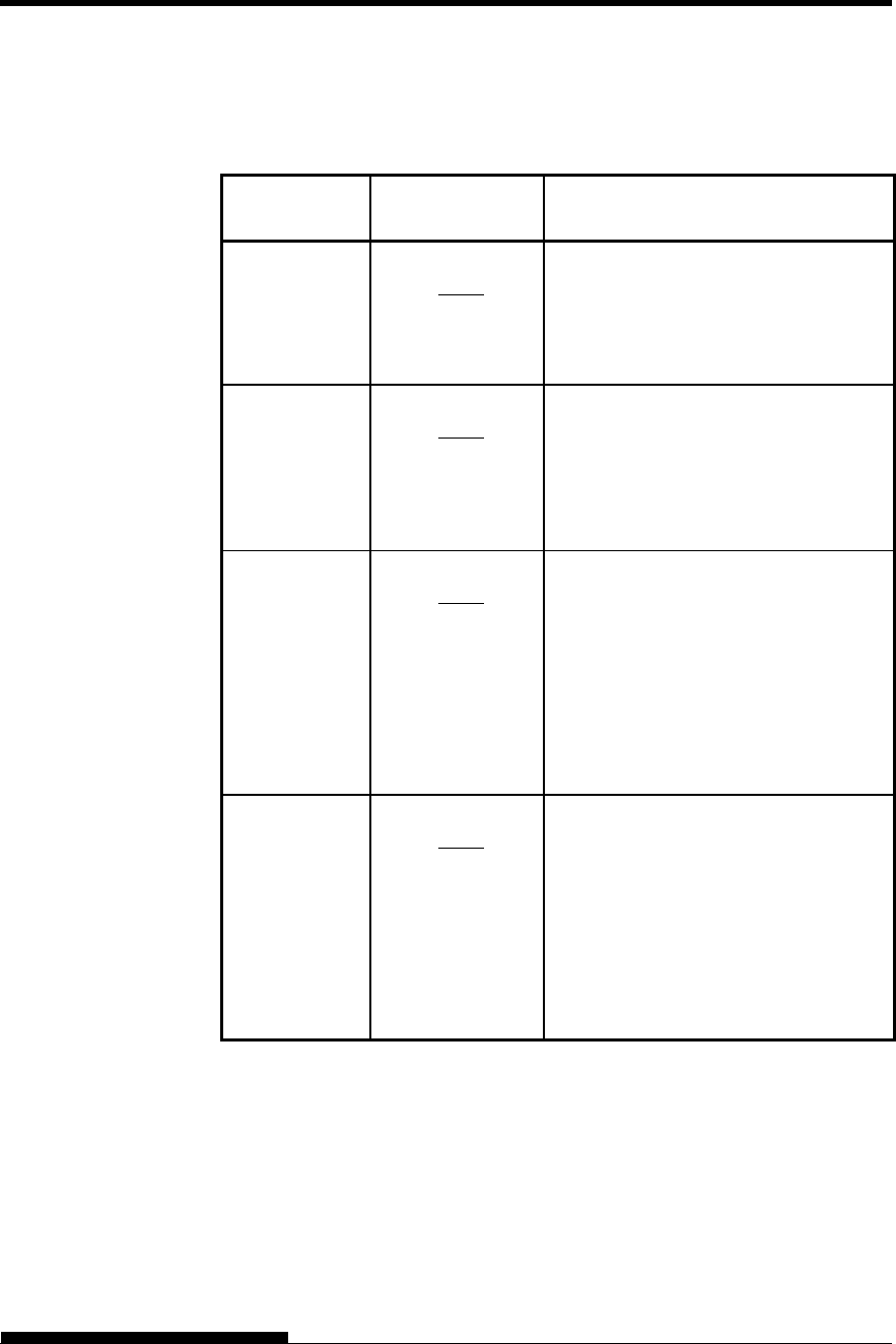
USING SETUP MODE
User's Manual 5-41
Table 5.6 ADJUST Items and Options (Cont.)
NOTE: Underlined options are the factory defaults.
ADJUST
Items Options Description
<RCNTAJL> -14/360, -9/360, -
4/360, 0/360
4/360, 9/360,
14/360,
GRAPHIC(*1)
Compensates for the forms feed error
accumulated through feeding of rear
continuous forms. (Last page)
<CUT-ADJ> -14/360, -9/360, -
4/360, 0/360
4/360, 9/360,
14/360,
GRAPHIC(*1)
Compensates the line spacing pitch on
the basis of the spacing error
accumulated for feeding single sheets
by10 inches.
Decreases or increases in increments of
1/360 inch in total.
<FCSFADJ> -14/360, -9/360, -
4/360, 0/360
4/360, 9/360,
14/360,
GRAPHIC(*1)
Compensates the line spacing pitch on
the basis of the spacing error
accumulated for feeding single sheets
by10 inches.
Decreases or increases in increments of
1/360 inch in total.
This option is available only when
paper is being loaded in the front cut
sheet feeder.
<RCSFADJ> -14/360, -9/360, -
4/360, 0/360
4/360, 9/360,
14/360,
GRAPHIC(*1)
Compensates the line spacing pitch on
the basis of the spacing error
accumulated for feeding single sheets
by10 inches.
Decreases or increases in increments of
1/360 inch in total.
This option is available only when
paper is being loaded in the rear cut
sheet feeder.

USING SETUP MODE
5-42 User's Manual
Table 5.6 ADJUST Items and Options (Cont.)
NOTE: Underlined options are the factory defaults.
ADJUST
Items Options Description
<FCNTLOR>
0/9, 1/9, 1.8/9,
2/9, 3/9, 4/9, ...,
15/9
It is possible to fine-tune the left blank
of the front continues form (the amount
of between the left paper edge to the
first dot for the first character).
This setting is effective only for the
front continues form at < FCNT-
SF:ENABLE >.
<FCNTLFN>
0/90, ..., 29/90
It is possible to fine-tune the left blan
k
of the front continues form by every
1/90 inches.
<RCNTLOR>
0/9, 1/9, 1.8/9,
2/9, 3/9, 4/9, ...,
15/9
It is possible to fine-tune the left blank
of the back continues form (the amount
of between the left paper edge to the
first dot for the first character).
This setting is effective only for the
back continues form at < RCNT-
SF:ENABLE >.
<RCNTLFN>
0/90, ..., 29/90
It is possible to fine-tune the left blan
k
of the back continues form by every
1/90 inches.
<CUTLOR>
0/9, 1/9, 1.8/9,
2/9, 3/9, 4/9, ...,
15/9
It is possible to fine-tune the left blank
of the cut sheet paper (the amount of
between the left paper edge to the first
dot for the first character).
This setting is effective only for the cut
sheet paper at < CUT-SF:ENABLE >.
<CUTLFN>
0/90, ..., 29/90
It is possible to fine-tune the left blan
k
of the cut sheet paper by every 1/90
inches.
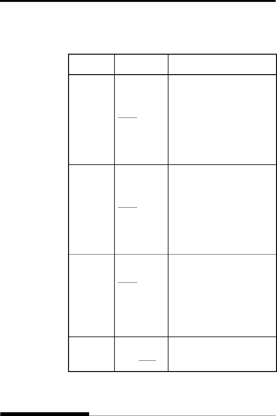
USING SETUP MODE
User's Manual 5-43
Table 5.6 ADJUST Items and Options (Cont.)
NOTE: Underlined options are the factory defaults.
ADJUST
Items Options Description
<FCNTCUT> 71 /180, 74 /180,
78 /180, 81 /180,
85 /180, 88 /180,
92 /180, 95 /180,
99 /180, 102/180,
106/180, 109/180,
113/180, 116/180,
120/180, 124/180,
128/180, 131/180,
135/180, 138/180,
142/180
It is possible to set the amount of blank
area of both sides of the front continues
form.
This setting is effective only for the
front continues form at <
FCNTARE:ENABLE1 or ENABLE2>
<RCNTCUT> 71 /180, 74 /180,
78 /180, 81 /180,
85 /180, 88 /180,
92 /180, 95 /180,
99 /180, 102/180,
106/180, 109/180,
113/180, 116/180,
120/180, 124/180,
128/180, 131/180,
135/180, 138/180,
142/180
It is possible to set the amount of blank
area of both sides of the back continues
form.
This setting is effective only for the
back continues form at <
RCNTARE:ENABLE1 or ENABLE2>.
<CUT-CUT> 7 /180, 10 /180,
14 /180, 17 /180,
20 /180, 24 /180,
28 /180, 31 /180,
35 /180, 38 /180,
43 /180, 46 /180,
50 /180, 53 /180,
57 /180, 60 /180,
64 /180, 67 /180,
71 /180
It is possible to set the amount of blank
area of both sides of the cut sheet paper.
This setting is effective only for the cut
sheet paper at < CUT-ARE:ENABLE1
or ENABLE2>.
<FRCSLNT>
7 /360, 14/360,
21/360, 28/360,
35/360
It is possible to set the threshol
d
of
skew detection during manual paper
insertion of a cut sheet.
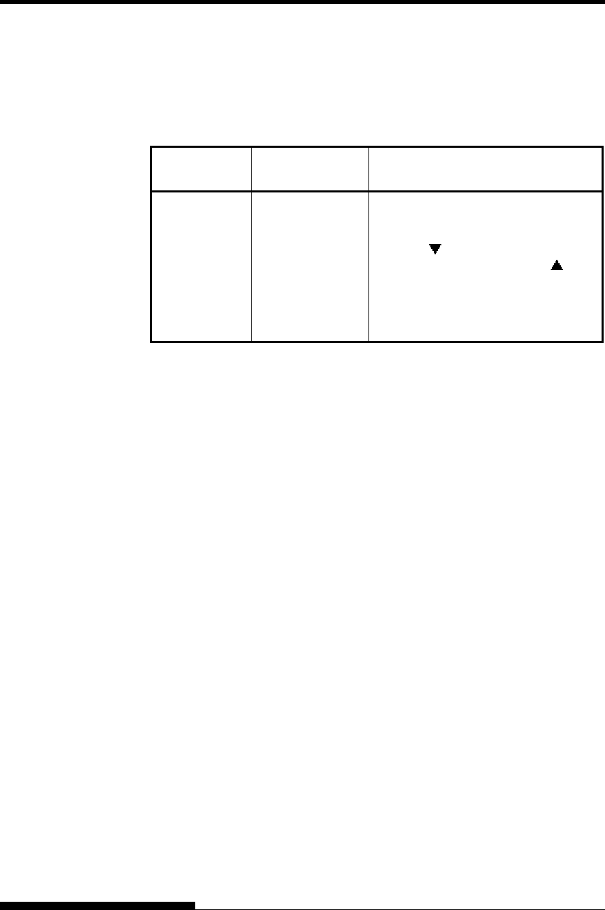
USING SETUP MODE
5-44 User's Manual
Table 5.6 ADJUST Items and Options (Cont.)
NOTE: Underlined options are the factory defaults.
ADJUST
Items Options Description
<==END==> (LED only)
Indicates the end of MENU1 items.
Press the button to print the first
item, <FCNTORG>. Press the
button to print the previous item, <
FRCSLNT > Press the ONLINE
button to reprint the <<FUNCTION>>
menu.
*1: When printing graphics, selecting “GRAPHIC” may result in the
printing of clearer graphics.
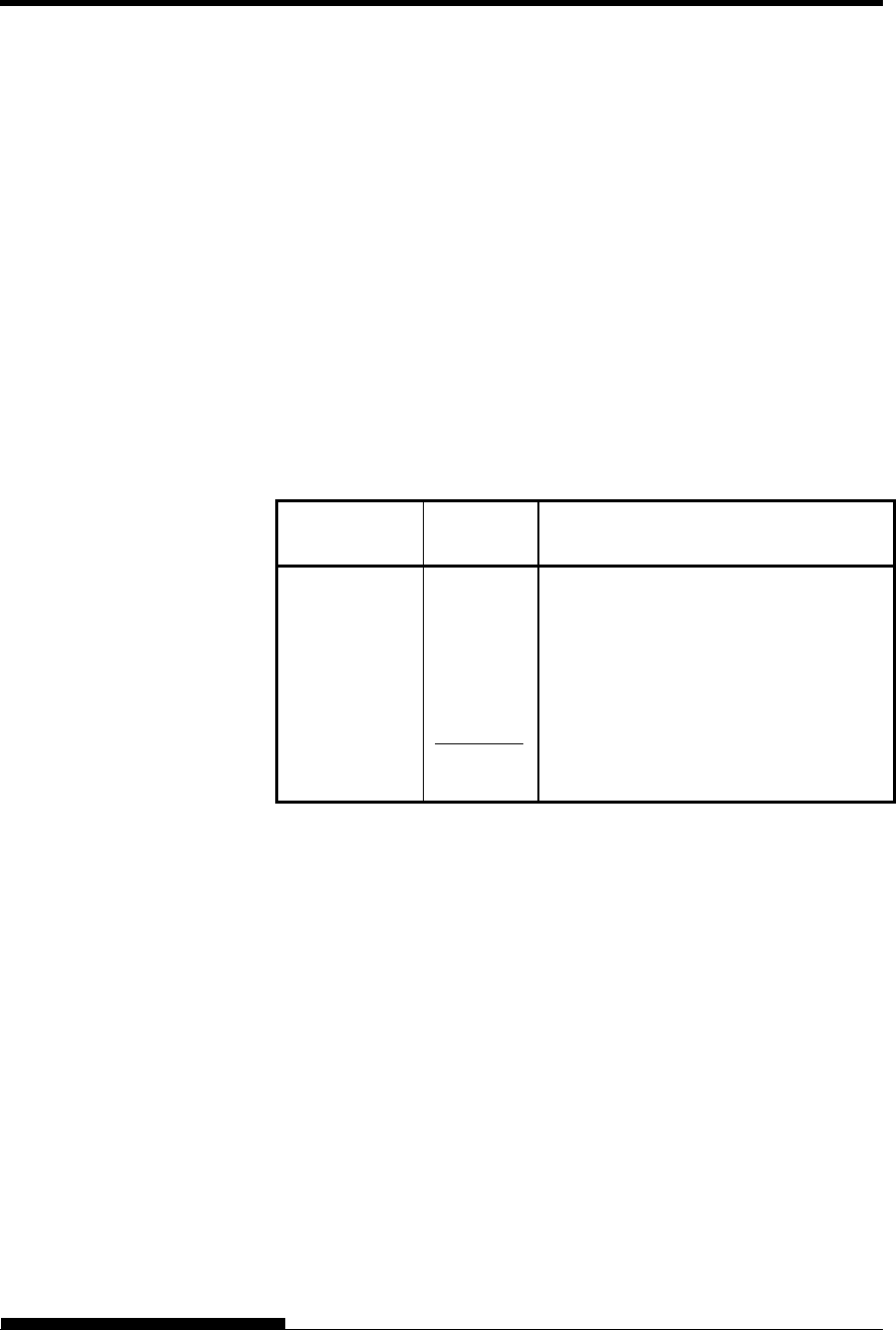
USING SETUP MODE
User's Manual 5-45
The CONFIG function defines the printer’s primary configuration. You
can set the following options to ensure that the printer meets your
requirements:
Tear off for continuous forms
Auto loading of single sheets
Direct decoding of certain commands
Enabling of the Area-over detection
Table 5.6 describes the CONFIG items and options. Items are listed in
the order they are printed. The procedure for changing the configuration
options is described after Table 5.7.
Table 5.7 CONFIG Items and Options
NOTE: Underlined options are the factory defaults.
CONFIG
Items Options Description
<TEAROFF> Auto or manual tear off feed.
AUTO Automatic tear off feed is valid but only
for continuous forms. Tear off feed can
also be done using the TEAR OFF
button.
MANUAL Automatic tear off feed is invalid, and
tear off feed must be done using the
TEAR OFF button.
CHANGING
CONFIGURATION
OPTIONS
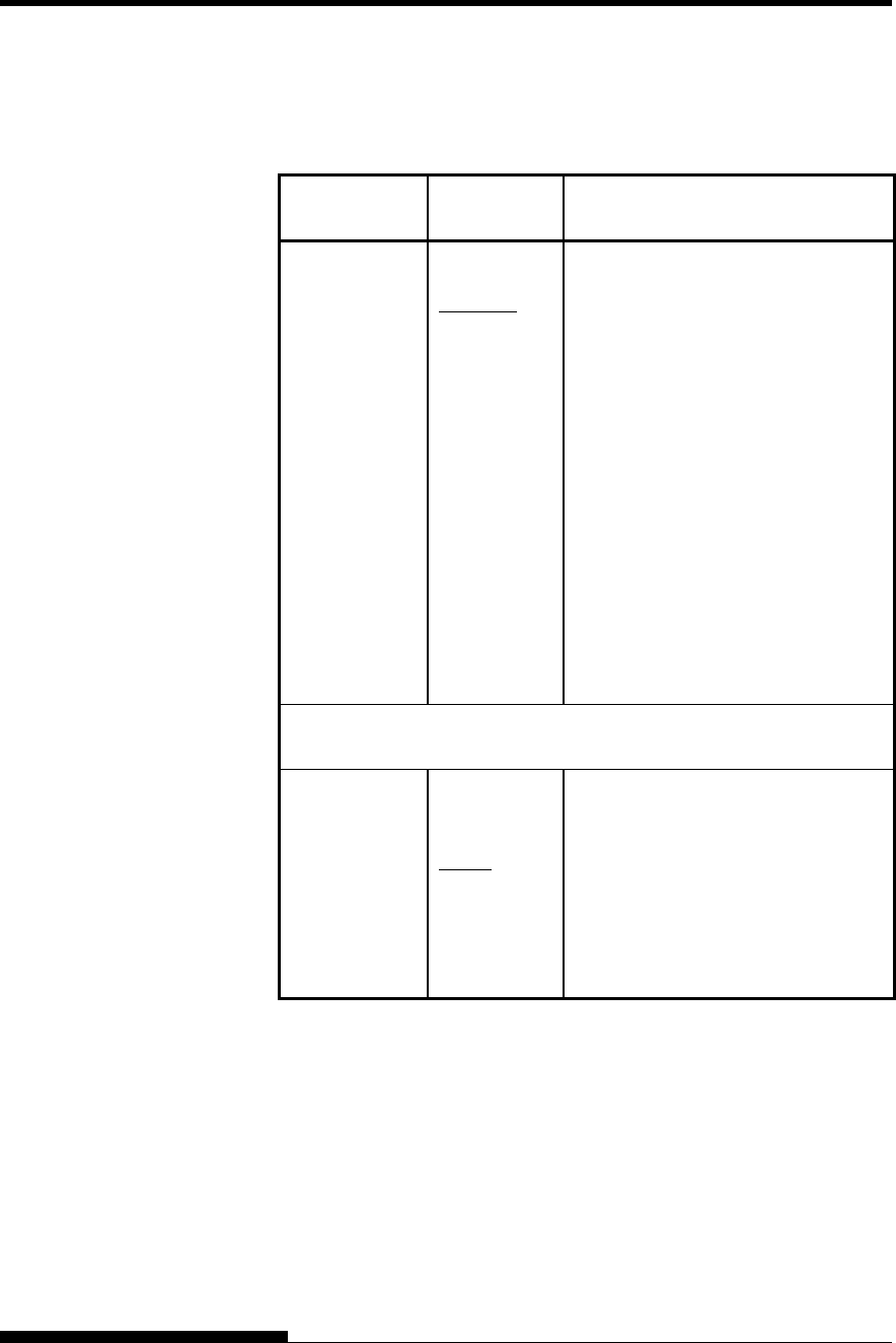
USING SETUP MODE
5-46 User's Manual
Table 5.7 CONFIG Items and Options (Cont.)
NOTE: Underlined options are the factory defaults.
CONFIG
Items Options Description
<TEARPOS> Tear off position.
VISIBLE Select this option when your software
positions forms to the next top-of
form after printing the last data. The
printer performs tear off feed without
adding a form feed when data transfer
has stopped.
ALWAYS Select this option when your software
stops after printing the last data. The
printer performs tear off feed after
adding a form feed when data transfer
has stopped.
Note: For both settings, tear off
positioning will fail if the page
length setting does not match the
actual perforation spacing.
The following <TEAR-EN> item is printed when TEAROFF:AUTO is
specified for the <TEAROFF> item.
<TEAR-EN> Tear off enabled time (offset time).
0 SEC
1 SEC
2 SEC
4 SEC
6 SEC
The offset time is from when data
transfer stops to when the printer
performs automatic tear off feed.
If the printer receives data again
within the offset time, the printer
does not perform automatic tear off
feed.
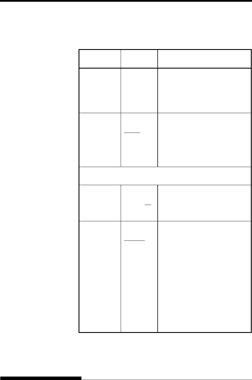
USING SETUP MODE
User's Manual 5-47
Table 5.7 CONFIG Items and Options (Cont.)
NOTE: Underlined options are the factory defaults.
CONFIG
Items Options Description
<TEAR-EN>
(continued)
In some application programs, data
transfer may stop temporarily due to
internal processing. This setting can
avoid an undesired tear off feed by
waiting for up to six seconds each
time data transfer stops.
<CUTLOAD> Single sheet auto loading.
AUTO Single sheet paper is automatically
loaded a certain time after you set the
paper.
BUTTON Single sheet paper can be loaded by
pressing the LOAD button.
The following <LOADTIM> item is printed when CUTLOAD:AUTO
is specified for the <CUTLOAD> item.
<LOADTIM> Auto load start time.
0.5, 1.0, 1.5,
2.0 2.5,
3.0SEC
Auto loading starts when this amount
of time passes after you set single
sheet paper.
<DECODE> Command decode timing.
DIRECT The printer decodes certain
commands immediately after
receiving data.
Example:
ESC SUB I, ESC CR
P (DPL24C+) ESC
Q # (IBM XL24E)
QUEUED The printer decodes commands after
storing all data (including commands)
in the input buffer. This speeds data
reception because the printer does not
require decoding time during data
reception.
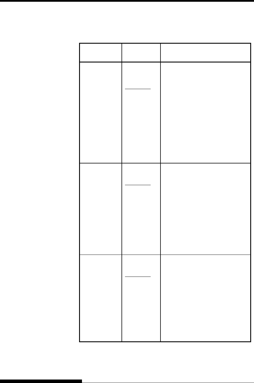
USING SETUP MODE
5-48 User's Manual
Table 5.7 CONFIG Items and Options (Cont.)
NOTE: Underlined options are the factory defaults.
CONFIG
Items Options Description
<FCNTARE> Area-over detection control of front
continuous forms.
ENABLE1 Detects the left and right edges of
paper when loading the paper.
ENABLE2 Detects the left and right edges of
paper at 13mm and 43mm from top
of the paper. This setting is
effective if the left and right edges
are not detected by <ENABLE1>
for preprint papers, etc.
DISABLE
Does not detect the edges. Select
this option when you are using
colored or preprinted paper.
<RCNTARE> Area-over detection control of rear
continuous forms.
ENABLE1
Detects the left and right edges of
paper when loading the paper.
ENABLE2 Detects the left and right edges of
paper at 13mm and 43mm from top
of the paper. This setting is
effective if the left and right edges
are not detected by <ENABLE1>
for preprint papers, etc.
DISABLE
Does not detect the edges. Select
this option when you are using
colored or preprinted paper.
<CUT-ARE> Area-over detection control of cut
sheets.
ENABLE1
Detects the left and right edges of
paper when loading the paper.
ENABLE2
Detects the left and right edges of
paper at 13mm and 43mm from top
of the paper. This setting is
effective if the left and right edges
are not detected by <ENABLE1>
for preprint papers, etc.
DISABLE Does not detect the edges. Select
this option when you are using
colored or preprinted paper.
Table 5.7 CONFIG Items and Options (Cont.)
NOTE: Underlined options are the factory defaults.
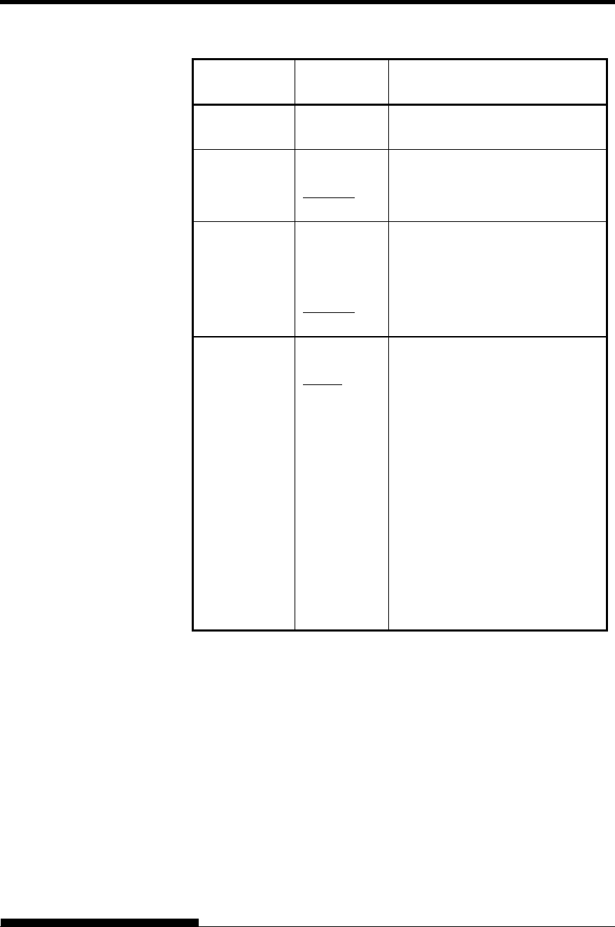
USING SETUP MODE
User's Manual 5-49
CONFIG
Items Options Description
<CUT-ONL> Printer status after loading paper in
offline mode for single sheets.
OFFLINE Remains offline after paper loading.
ONLINE Goes into online after paper
loading.
<CNT-ONL> Printer status after loading paper in
offline mode for continuous forms.
OFFLINE Remains offline after paper loading.
ONLINE Goes into online after paper
loading.
<LOCK> Lock function of setup mode.
NONE Enables all buttons on the control
panel.
SETUP Disables the setup-related buttons
to keep the printer from entering
setup mode during the offline state.
ALL Disables the setup-related buttons
and the MENU button.
Once this setting has been selected,
setup mode cannot be entered from
the control panel. To cancel this
setting, turn the power on while
simultaneously pressing the HI
IMPACT, PAPER PATH, and
LF/FF buttons.
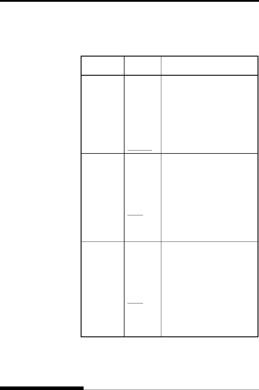
USING SETUP MODE
5-50 User's Manual
Table 5.7 CONFIG Items and Options (Cont.)
NOTE: Underlined options are the factory defaults.
CONFIG
Items Options Description
<//S//> Effectiveness of the Cut Sheet
Selection command (//S//).
ENABLE Makes the command effective.
Note: The Cut Sheet Selection
command (//S//) changes the
paper source to the paper table
and waits for manual insertion
of a cut sheet.
DISABLE Makes the command ineffective.
<FCNT-PE> Detection of end of front continuous
forms.
TRACTOR
Paper end is detected by the sensor on
the tractor unit.
Paper-end unprinted area:
Continuous forms: About 101 mm
EDGE
Regardless of paper end, printing
continues near to the edge of paper.
Paper-end unprinted area: About 4
mm for both continuous forms
<RCNT-PE> Detection of end of rear continuous
forms.
TRACTOR
Paper end is detected by the sensor on
the tractor unit.
Paper-end unprinted area:
Continuous forms: About 157 mm
EDGE
Regardless of paper end, printing
continues near to the edge of paper.
Paper-end unprinted area:
About 4 mm for both continuous
forms
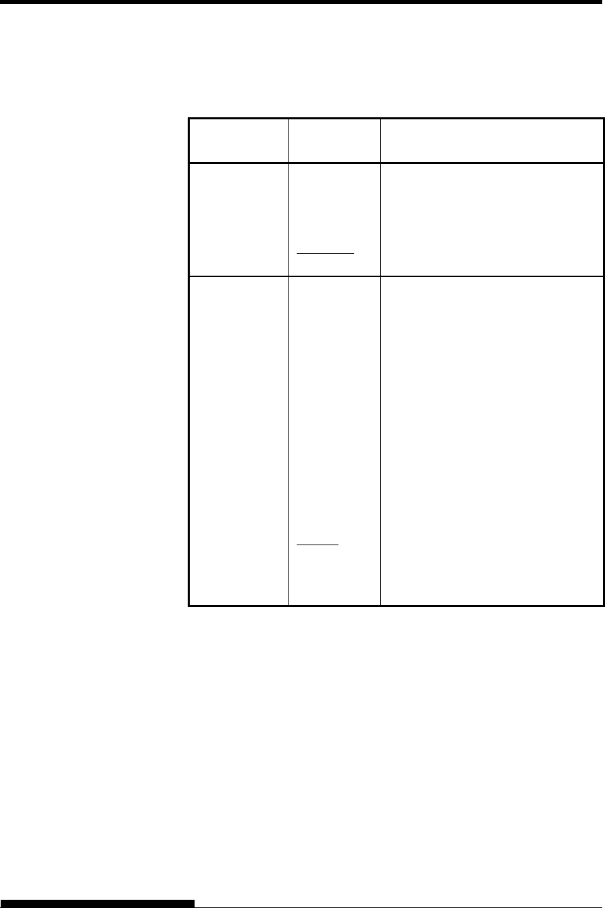
USING SETUP MODE
User's Manual 5-51
Table 5.7 CONFIG Items and Options (Cont.)
NOTE: Underlined options are the factory defaults.
CONFIG
Items Options Description
GATHER Setting of ribbon protective control at
a line feed on continuous forms
ENABLE The protective control is executed.
DISABLE The protective control is not
executed.
CUT-CTL Setting of retracting control at
canceling TEAR OFF of continuous
forms.
PRCISIN The precision-prioritized retracting
control is executed.
It retracts a certain amount of paper
(the top part of the paper which hangs
out from the TOFS), and then moves
back to the position before TEAR
OFF. If TOFS detects paper end
when a certain amount of paper is
retracted, it executes the continuous
forms save operation and then
executes the paper loading operation.
SPEED The speed-prioritized retracting
control is executed.
It retracts the paper by the amount the
paper was advanced.
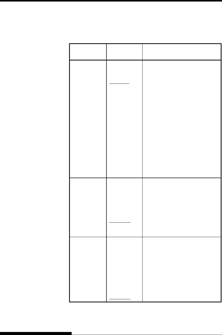
USING SETUP MODE
5-52 User's Manual
Table 5.7 CONFIG Items and Options (Cont.)
NOTE: Underlined options are the factory defaults.
CONFIG
Items Options Description
SKIP-PR Setting of printing speed change
processing (skip)
ENABLE The skip processing is executed.
When a certain amount of blank
spaces are found in a line, it
changes the printing speed for the
blank spaces.
DISABLE The skip processing is not executed.
It does not change the printing
speed for the blank spaces.
- If the printing speed of the
printing data varies before and
after the blank spaces (such as
LQ characters + blank space +
CQ characters), it changes
printing speeds regardless of
this setting.
STATUS Setting of the asynchronous status
function
ENABLE The status information is stored in
the send buffer by a nibble mode
request.
DISABLE The status information is not stored
in the send buffer by a nibble mode
request.
BANDCTL Setting of reducing backward line
feeds as much as possible.
Backward line feeds occur when
printing vertical enlargement
characters or multi-path characters
which involve several printing
paths for a print activation.
ENABLE Reduce control is performed.
DISABLE Reduce control is not performed.

USING SETUP MODE
User's Manual 5-53
Table 5.7 CONFIG Items and Options (Cont.)
NOTE: Underlined options are the factory defaults.
CONFIG
Items Options Description
TOF-CTL Setting of priority on TOF control to
a printer driver specification or a
setup specification. TOF control
determines the amout of the top
margin when paper is fed to the home
position.
DRIVER Driver specification is given priority.
SETUP Setup specification is given priority.
<FCNT-SF> SET-FREE function of front
continues papers is set.
SET-FREE function is to adjust
automatically the start printing
position of print data by detecting the
left edge position of paper during
paper feeding.
EBANLE Enables SET-FREE function
DISABLE Disables SET-FREE function
<RCNT-SF> Enables SET-FREE function of the
back continues paper.
EBANLE Enables SET-FREE function
DISABLE Disables SET-FREE function
<CUT-SF> Enables SET-FREE function of the
cut sheet paper.
EBANLE Enables SET-FREE function
DISABLE Disables SET-FREE function
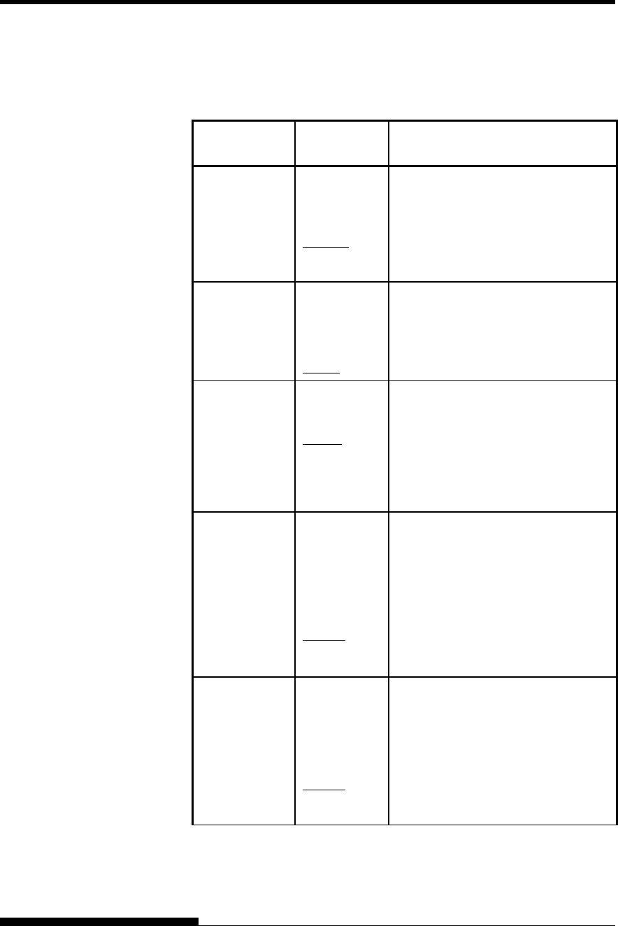
USING SETUP MODE
5-54 User's Manual
Table 5.7 CONFIG Items and Options (Cont.)
NOTE: Underlined options are the factory defaults.
CONFIG
Items Options Description
<CUTEDIR> Selection of the eject direction of cut
sheets with manually feeding of cut
sheets
FRONT Ejected to the front.
REAR Ejected to the rear.
<CSFEDIR> Selection of the eject direction of cut
sheets with use of a CSF
FRONT Ejected to the front.
REAR Ejected to the rear.
<CUTEJCT> Selection for automatic ejection of
cut sheets
AUTO Automatic ejection of cut sheets
when no cut sheet is detected
MANUAL No automatic ejection of cut sheets
when no cut sheet is detected
<FL-CENT> Selection of the print carrier position
when paper is fed via a front path
(with feeding of continuous forms
paper from the front, use of a front
CSF, and manual feeding of cut
sheets)
POSN1 Position 1: Column 31
POSN2 Position 2: Column 42
<RL-CENT> Selection of the print carrier position
when paper is fed via a front path
(with feeding of continuous forms
paper from the rear and use of a rear
CSF)
POSN1 Position 1: Column 31
POSN2 Position 2: Column 42
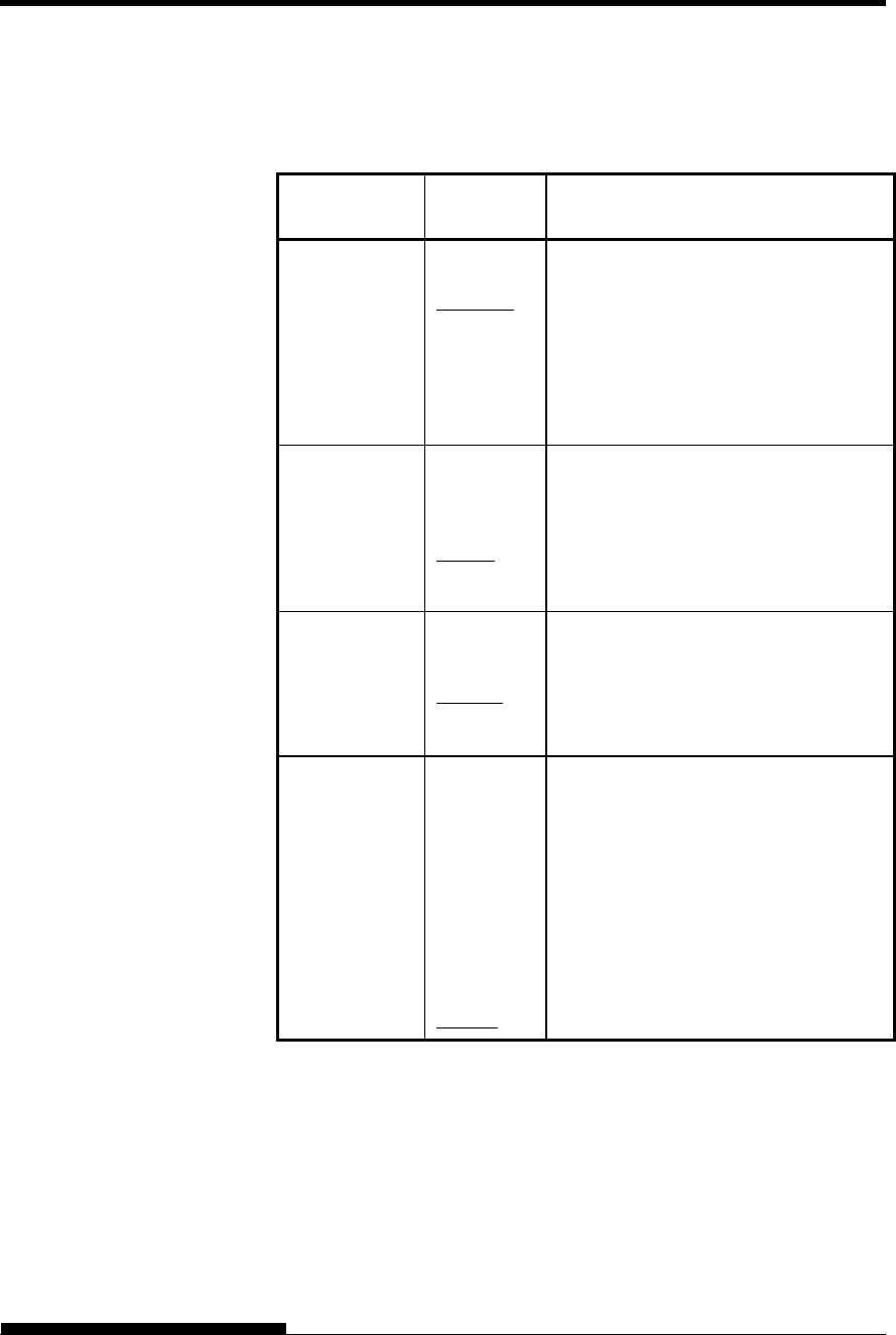
USING SETUP MODE
User's Manual 5-55
Table 5.7 CONFIG Items and Options (Cont.)
NOTE: Underlined options are the factory defaults.
CONFIG
Items Options Description
<SKEWCNT> Detection of paper feed skew
PRCISIN Enables paper feed skew detection.
Precision is the first priority.
SPEED Enables paper feed skew detection.
Speed is the first priority.
DISABLE Disables paper feed skew detection.
<FF-CODE> Selection of the method of processing
for the FF code is received in cut sheet
mode or for the “LF/FF” switch
EJECT Ejects cut sheets.
FORM-FD Uses a page break.
<CSFBIN1> Selection of the CSF for bin 1 if both a
front CSF and rear CSF are mounted
FRONT Front CSF
REAR Rear CSF
<CNT-LD> Selection for the paper feeding of
continuous forms paper
PRCIS-1 Precision is the first priority.
PRCIS-2 Speed is the first priority.
Reduces the disturbance of line break
outstretching fold of the paper by over
feeding during the process of paper
feeding
SPEED Speed is the first priority.
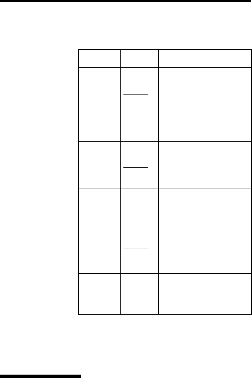
USING SETUP MODE
5-56 User's Manual
Table 5.7 CONFIG Items and Options (Cont.)
NOTE: Underlined options are the factory defaults.
CONFIG
Items Options Description
<CSF-LD> Selection of the method of feeding
from the CSF
NORMAL Feeds paper directly from the CSF
hopper.
SWBACK Feeds paper from the CSF hopper to
either the Paper table used with a
front CSF or the stacker used with a
rear CSF. Then, that paper is fed
again.
<CSFAPTC> Paper thickness detection with use of
a CSF
NORMAL Sheet of paper that is fed immediately
after the feed bin is switched
ALWAYS Every sheet of paper that is fed
<LF-CTL> Selection for LF mode
PRCISIN Precision is the first priority.
SPEED Speed is the first priority.
<PR-MODE> Selection for print mode
(standard/hi speed/low noise)
NORMAL Prints in standard mode.
HISPEED Prints in hi-speed mode.
QUIET Prints in low-noise mode.
<HI-IMPT> Selection for high printing pressure
mode
ENABLE Prints in high impact mode.
DISABLE Prints in standard impact mode.
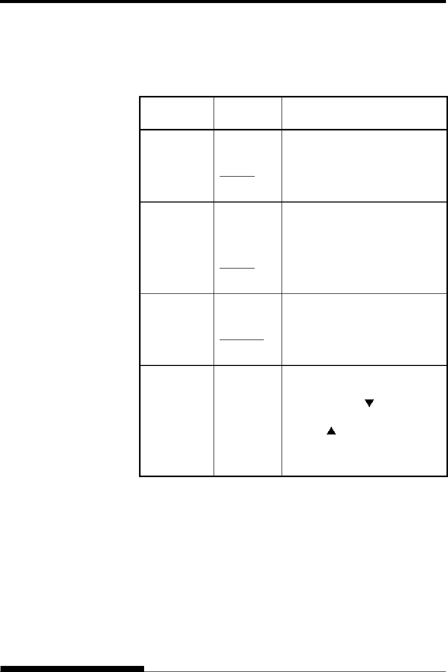
USING SETUP MODE
User's Manual 5-57
Table 5.7 CONFIG Items and Options (Cont.)
NOTE: Underlined options are the factory defaults.
CONFIG
Items Options Description
<LQ-MODE > Selection for letter quality printing
mode
MODE1 Prints in 180CPS printing mode.
MODE2 Prints in 125CPS printing mode.
<DQ-MODE > Selection for draft quality printing
mode
MODE1 Prints in 720CPS printing mode.
MODE2 Prints in 540CPS printing mode.
MODE3 Prints in 800CPS printing mode.
<POW-POS > It is possible to set the paper position
at power on.
NORMAL Current position
TEAROFF Tear off position
<==END==> (LED only)
Indicates the end of the CONFIG
item list. Press the button to print
the first item, which is <TEAROFF>.
Press the button to print the
previous item. Press the ONLINE
button to reprint the
<<FUNCTION>> menu.
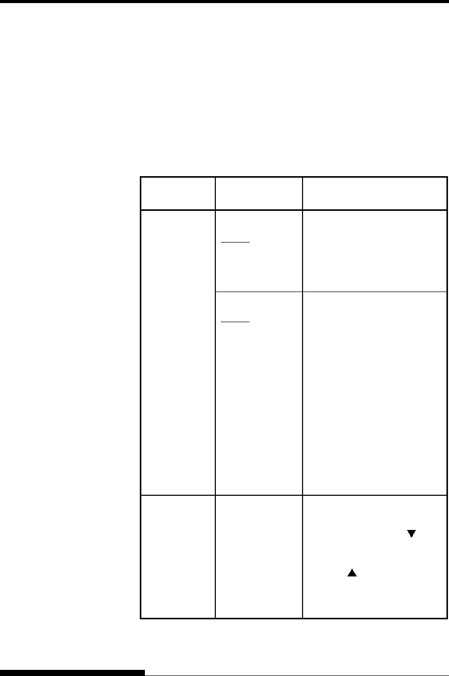
USING SETUP MODE
5-58 User's Manual
The GAP-ADJ function adjusts the gap between the print head and
the paper. The automatic paper thickness control (APTC) feature is
built in this printer. If you adjust the gap manually or fix the gap,
change the option of GAP-ADJ function.
For the procedure how to change the options refer to the section
Setup Mode Example earlier in this chapter.
Table 5.8 GAP-ADJ Items and Options
NOTE: Underlined options are the factory defaults.
GAP-ADJ
Items Options Description
<AMOUNT> (LED type) Specifies the print head gap.
AUTO The print head gap is set
automatically.
MANUAL Turn the paper thickness dial
(indicator) manually.
(LCD type)
AUTO The print head gap is set
automatically.
GAP-1
GAP-2
GAP-3
GAP-4
GAP-5
GAP-6
GAP-7
GAP-8
GAP-9
GAP-A
GAP-B
GAP-C
GAP-D
The print head gap is set
selected manual gap.
<==END==> (LED only)
Indicates the end of the GAP-
ADJ item list. Press the
button to print the first item,
which is <AMOUNT>.
Press the button to print the
previous item. Press the
ONLINE button to reprint the
<<FUNCTION>> menu.
HEAD GAP
ADJUSTMENT
ITEMS AND
OPTIONS

USING SETUP MODE
User's Manual 5-59
This section describes how to exit setup mode and save any changes you
made:
To exit setup mode immediately, select the SAVE & END (for LED
type) SAVE&EXIT (for LCD type) function.
Any settings changed while in setup mode are saved as the new power-
on defaults for the printer. The new defaults remain active until you
change them again.
NOTE (LED only)
The only way to exit setup mode without saving your changes is to
turn off the printer. When you turn the printer back on, the previous
default settings are used.
Procedure (for LED type)
To exit setup mode and save your changes using SAVE/END, proceed as
follows:
1. Print the <<FUNCTION>> menu.
The <<FUNCTION>> menu should be the last printed line on
the page. If the menu is not printed, press the ONLINE button to
print the menu. The <<FUNCTION>> menu is shown below:
<< FUNCTION >>
SAVE&END MENU1 MENU2 HARDWRE ADJUST CONFIG GAP-ADJ DEFAULT LIST SELF-
T
ST
HEX-DUMP V-ALMNT INITIAL
2. Select the SAVE/END function.
Make sure that the cursor on the left edge of the aluminum print
guide is positioned under SAVE & END. Press the button or
the button to select SAVE & END. The printer exits setup
mode and returns online (the ONLINE indicator lights green).
Any changes you made while in setup mode are saved.
Procedure (for LCD type)
To exit setup mode and save or cancel your changes using SAVE/EXIT
function, proceed as follows:
1. Push SAVE/EXIT button.
Push SAVE/EXIT button, then “ :SAVE :CANCEL” is
displayed on LCD PANEL
2. Push or button.
Push to save changing.
Push to cancel changing.
EXITING AND
SAVING

USING SETUP MODE
5-60 User's Manual
This section describes how to reset the printer’s power-on defaults,
all of the factory defaults, or the factory defaults only for MENU1
and MENU2.
Resetting Power-On Defaults
Power-on defaults are the settings saved in the printer’s permanent
memory. The defaults are enabled whenever you turn the printer on.
The only (LED type) way to reset the power-on defaults is to turn the
printer off and then on again. This method is useful if you have made
changes in setup mode that you do not want to save. LCD type, save or
cancel options are available on exit menu.
Resetting Factory Defaults
Factory defaults are those settings preselected at the factory. For a list of
the printer’s factory defaults, see the section Printing a List of Selected
Options earlier in this chapter. To reset the factory defaults for all
functions, proceed as follows:
1. Turn off the printer.
2. While pressing the LOAD and, TEAR OFF buttons, turn on the
printer. Continue to press the two buttons until the printer beeps.
The factory defaults are now reset.
Another available method is to select INITIAL in SETUP mode.
The method of making settings is the same as the method for
selecting DEFAULT on the next page, except that INITIAL
must be selected instead of DEFAULT.
Resetting Factory Defaults in MENU1 and
MENU2
This method resets factory defaults for MENU1 and MENU2 options,
listed in Table 5.4, but does not reset the printer hardware, print position
adjustment, and configuration options.
Procedure (for LED type)
To reset the factory defaults in MENU1 and MENU2, select DEFAULT
in SETUP mode. Detail of method as follows:
1. Enter setup mode (LED type).
Press the SETUP button until the printer beeps. Wait for the
printer to stop printing and check that the following
<<FUNCTION>> menu is printed:
RESETTING
DEFAULTS

USING SETUP MODE
User's Manual 5-61
<< FUNCTION >>
SAVE&END MENU1 MENU2 HARDWRE ADJUST CONFIG GAP-ADJ DEFAULT LIST SELF-
T
ST
HEX-DUMP V-ALMNT INITIAL
2. Select the DEFAULT function (LED type).
Repeatedly press the “TEAR OFF” or “LOAD” button to
position the cursor on the left edge of the aluminum print guide
on DEFAULT. Press the button or the button to select the
DEFAULT function. The printer reprints the <<FUNCTION>>
menu. The default values in MENU1 and MENU2 are now reset
(not saved yet).
3. Save reset values (LED type).
To exit setup mode and save the new defaults, make sure that
the cursor on the left edge of the aluminum print guide are
positioned on SAVE & END, then press the MICRO button
or the MICRO button.
Procedure (for LCD type)
To reset the factory defaults in MENU1 and MENU2, select DEFAULT
in SETUP mode. Detail of method as follows:
1. Enter setup mode (LCD type).
Press the SETUP button at offline state. Check that the “SETUP
MODE” is displayed on LCD panel.
2. Select the DEFAULT function (LCD type).
Repeatedly press the “ ” or “ ” button to display “SUB
FUNCTION”. And then press the“ ” button to move lower
layer. And then repeatedly press the “ ” or “ ” button to
display “DEFAULT”. And then press the “SELECT” button to
reset the default values in MENU1 and MENU2 (not saved yet).
3. Save reset values (LCD type).
Exit setup mode, saving the factory defaults.
Push SAVE/EXIT button. Check that “ :SAVE :CANCEL” is
displayed on LCD panel. Then press the“ ” button.

USING SETUP MODE
5-62 User's Manual
This section describes how to use the following diagnostic functions:
SELF-TST
HEX-DUMP
V-ALMNT
These functions are used for checking print quality and diagnosing
printer problems. HEX-DUMP also provides useful information for
programmers.
Printing the Self-Test
The SELF-TST function prints test pages to check how the printer
operates independently of your computer. The self-test does not check
the interface between the computer and the printer.
The self-test prints the printer’s firmware version, its resident emulations,
and all of the characters available in the currently selected character set.
If the DPL24C PLUS emulation is selected for MENU1, the self-test is
printed using the settings currently assigned to MENU1.
Procedure
This procedure assumes that you are in setup mode. To print the self-test,
make sure that continuous forms paper is loaded into the printer.
Then proceed as follows :
1. Print the <<FUNCTION>> menu.(LED)
The <<FUNCTION>> menu should be the last printed line on
the page. If the menu is not printed, press the ONLINE button to
print the menu. If you are using the HEX-DUMP function,
press the “TEAR OFF” or “LOAD” button instead of the
ONLINE button to print the menu. The following
<<FUNCTION>> menu is printed:
<< FUNCTION >>
SAVE&END MENU1 MENU2 HARDWRE ADJUST CONFIG GAP-ADJ DEFAULT LIST SELF-TST
HEX-DUMP V-ALMNT INITIAL
2. Select the SELF-TST function.(LED)
Repeatedly press the “TEAR OFF” or “LOAD” button to
position the cursor on the left edge of the aluminum print guide
on SELF-TST, and then press the “ ” button or the “ ”
button. The printer selects SELF-TST and starts printing. A
short help menu is printed at the top of the page, followed by the
self-test. Note that the printer is not online during self-test
printing.
USING THE
DIAGNOSTIC
FUNCTIONS

USING SETUP MODE
User's Manual 5-63
1. Move to TOP MENU of SETUP MODE.(LCD)
Press the “ ” button until “SETUPMODE” is displayed on
LCD panel.
2. Select the SELF-TST function.(LCD)
Repeatedly press the “ ” or “ ” button to display
“SELFDIAGNOSTIC”. And then press the“ ” button to move
lower layer. And then repeatedly press the “ ” or “ ” button
to display “SELF-TEST”. And then press the “SELECT” button
to start self-test printing. A short help menu is printed at the top
of the page, followed by the self-test. Note that the printer is not
online during self-test printing.
3. Examine the self-test page.
A sample self-test page is shown in Chapter 2. To pause during
self-test printing, press the “LOAD” button. To resume self-test
printing, press the “LOAD” button again.
4. Exit the SELF-TST function.
Exit the SELF-TST function in either of the following ways:
To exit SELF-TST and remain in setup mode, press the
LF/FF button. The <<FUNCTION>> menu is then
reprinted (LED type).
To exit SELF-TST and return online, press the ONLINE
button. The printer permanently saves any changes made
while in setup mode and returns online.
The self-test can also be started by turning off the printer, and then
pressing the LF/FF button while turning the printer back on. As
described in Chapter 2, this method is useful when you first set up the
printer.

USING SETUP MODE
5-64 User's Manual
Printing Hex Dumps
The HEX-DUMP function prints data and commands in hexadecimal
characters and abbreviated control codes. The IBM character set 2 is
used for printing (see Appendix E). The HEX-DUMP function is useful
for checking whether your computer is sending the correct commands to
the printer and whether the printer is executing the commands correctly.
It is also useful for debugging software programs.
Procedure
To print hex dumps, make sure that continuous forms paper is loaded
into the printer. Then proceed as follows:
1. Enter setup mode(LED).
Press the SETUP button until the printer beeps. Wait for the
printer to stop printing and check that the following
<<FUNCTION>> menu is printed:
2. Select the HEX-DUMP function (LED) .
<< FUNCTION >>
SAVE&END MENU1 MENU2 HARDWRE ADJUST CONFIG GAP-ADJ DEFAULT LIST SELF-TST
HEX-DUMP V-ALMNT INITIAL
Repeatedly press the “TEAR OFF” or “LOAD” button to
position the cursor on the left edge of the aluminum print guide
on HEX-DUMP, then press the button or the button to
select the HEX-DUMP function. The printer goes online and
prints a header and a short help menu.
1. Enter setup mode (LCD) .
Press the SETUP button at offline state. Check that the “SETUP
MODE” is displayed on LCD panel.
2. Select the HEX-DUMP function (LCD).
Repeatedly press the “ ” or “ ” button to display
“SELFDIAGNOSTIC”. And then press the“ ” button to move
lower layer. And then repeatedly press the “ ” or “ ” button
to display “HEX-DUMP”. And then press the “SELECT”
button. The printer goes online and prints a header and a short
help menu.
3. Print the hex dump.
To start hex dump printing, send your file or program to the
printer. The printer goes online and prints the hex dump.
Press the LOAD button to pause during hex dump printing. To
resume hex dump printing, press the “LOAD” button again.
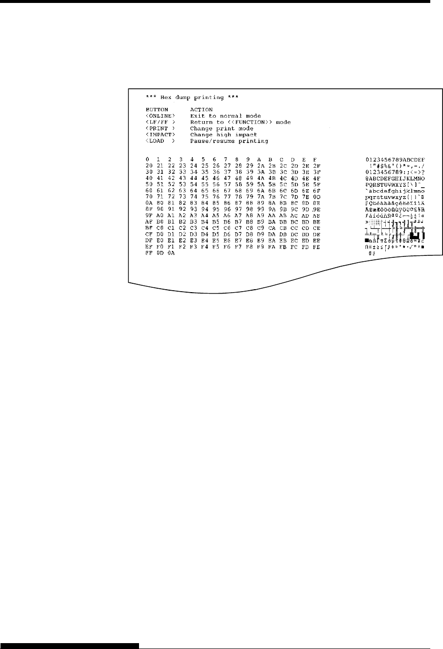
USING SETUP MODE
User's Manual 5-65
NOTE
When hex dump printing stops, data that is less than one
line printed yet, to print remaining data exit Hex-Dump
mode(push LF/FF or ONLINE).
Sample hex dump
4. Exit the HEX-DUMP function.
Exit the HEX-DUMP function in either of the following ways:
To remain in setup mode, press the LF/FF button. The
<<FUNCTION>> menu is then reprinted (LED type). For
details on other functions, see other sections in this chapter.
To return to online normal mode, press the ONLINE button.
If you press the ONLINE button while the hex dump is
printing, the printer immediately switches to normal online
mode, but data that was sent to the printer is printed in
normal mode. At same time the printer permanently saves
any changes made while in setup mode.
You can also enter hex dump mode, by turning off the printer, and then
turning the printer back on while simultaneously pressing the ONLINE
button and the LF/FF button until the printer beeps.

USING SETUP MODE
5-66 User's Manual
Checking Vertical Print Alignment (V-ALMNT)
The V-ALMNT function corrects the vertical character displacement that
sometimes occurs with bidirectional printing. Characters printed from
left to right are not aligned with characters printed from right to left as
shown below:
This example shows how printing looks
when characters are vertically
misaligned. Note that the left
margin is not straight.
If you notice misaligned printing, use the following procedure to check
and correct the vertical print alignment.
Procedure
Make sure that continuous forms paper is loaded in the printer. If
possible, use forms at least 356 mm (14 inches) wide to avoid printing on
the platen. However, you can also use letter or A4 size forms if you set
the WIDTH option in MENU1 to 8 inches. See the section Changing
MENU1 and MENU2 Items and Options for details. Then proceed as
follows to check and correct vertical print alignment:
1. Enter setup mode (LED).
Press the SETUP button until the printer beeps. Wait for the
printer to stop printing and check that the following
<<FUNCTION>> menu is printed:
<< FUNCTION >>
SAVE&END MENU1 MENU2 HARDWRE ADJUST CONFIG GAP-ADJ DEFAULT LIST SELF-TST
HEX-DUMP V-ALMNT INITIAL
2. Select the V-ALMNT function (LED).
Repeatedly press the “TEAR OFF” or “LOAD” button to
position the cursor at V-ALMNT, then press the “ ” button or
the “ ” button to select the V-ALMNT function. The printer
prints the help menu then starts printing rows of parallel bars
using letter quality speed.
1. Enter setup mode (LCD) .
Press the SETUP button at offline state. Check that the “SETUP
MODE” is displayed on LCD panel.
2. Select the V-ALNMNT function (LCD) .
Repeatedly press the “ ” or “ ” button to display
“SELFDIAGNOSTIC”. And then press the“ ” button to move
lower layer. And then repeatedly press the “ ” or “ ” button
to display “V-ALNMNT”. And then press the “SELECT”
button. The printer prints the help menu then starts printing
rows of parallel bars using letter quality speed.
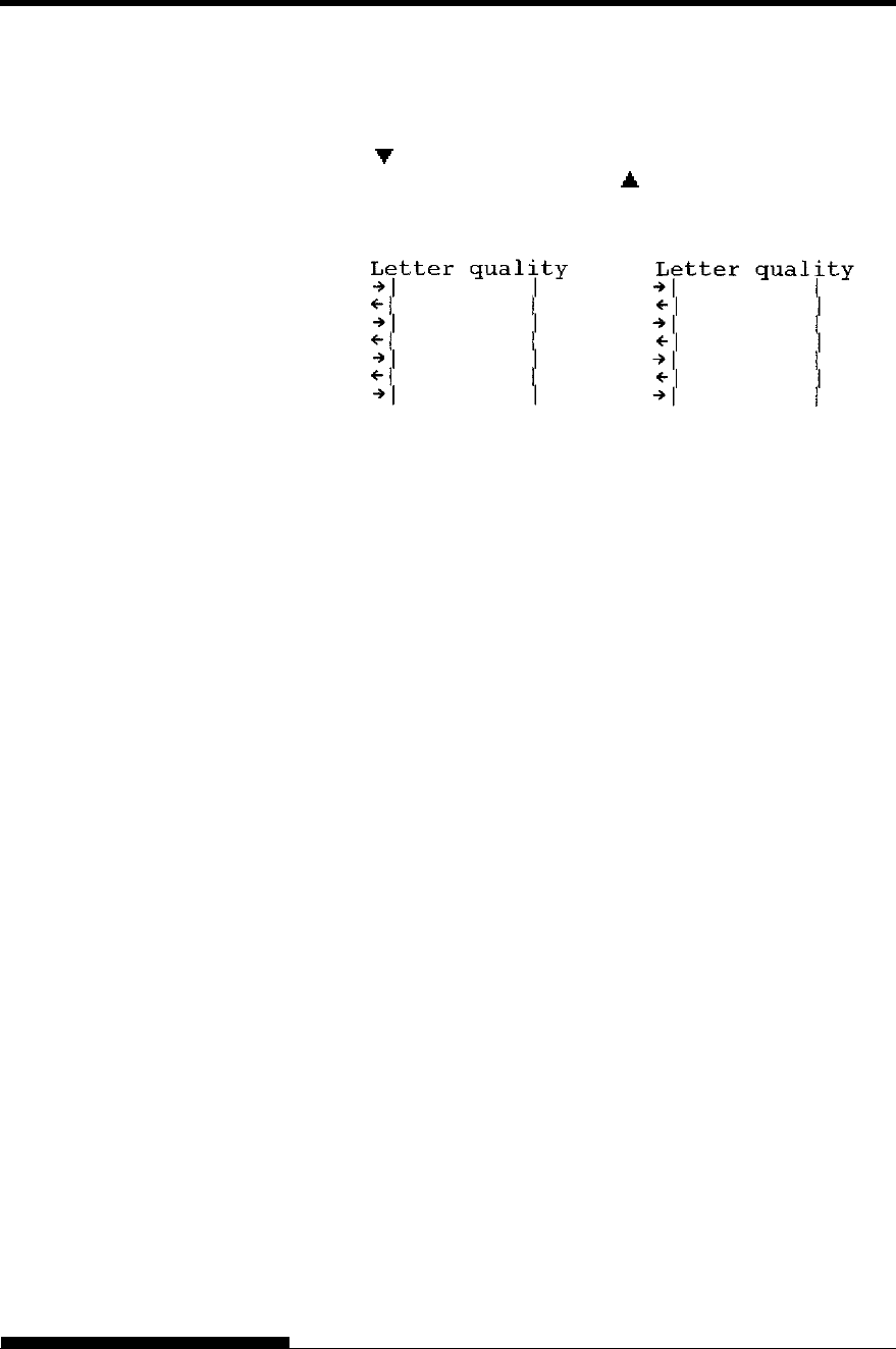
USING SETUP MODE
User's Manual 5-67
3. Adjust the vertical print alignment at letter quality speed.
Examine the parallel bars. If the bars are aligned (not jagged),
go to step 4. If the bars are offset to the left, repeatedly press the
“ ” button until the bars are aligned. If the bars are offset to
the right, repeatedly press the “ ” button until the bars are
aligned. (In the following figure, the first line is assumed to be
printed from left to right.)
Bars offset to the left Bars offset to the right
Press the HI IMPACT button to enter Hi Impact mode. Make
similar adjustments.
4. Adjust the vertical print alignment at letter 2 speed.
Press the “TEAR OFF” button to switch from letter speed to
letter 2 speed.
Examine the parallel bars and adjust the vertical print alignment
as described in step 3.
HI IMPACT button is disable at letter 2 speed in V-ALMNT
function.
HI IMPACT mode of letter quality 2 is the same speed as HI
IMPACT mode of letter quality.
5. Adjust the vertical print alignment at correspondence speed.
Press the “TEAR OFF” button to switch from letter 2 speed to
correspondence speed.
Examine the parallel bars and adjust the vertical print alignment
as described in step 3.
Press the HI IMPACT button to enter Hi Impact mode. Make
similar adjustments.
6. Adjust the vertical print alignment at draft speed.
Press the “TEAR OFF” button to switch from correspondence
speed to draft speed.
Examine the parallel bars and adjust the vertical print alignment
as described in step 3.
Press the HI IMPACT button to enter Hi Impact mode. Make
similar adjustments.
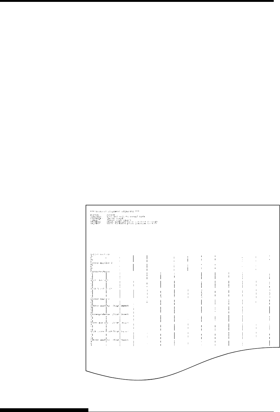
USING SETUP MODE
5-68 User's Manual
7. Adjust the vertical print alignment at high draft speed.
Press the “TEAR OFF” button to switch from draft speed to
high draft speed.
Examine the parallel bars and adjust the vertical print alignment
as described in step 3.
Press the HI IMPACT button to enter Hi Impact mode. Make
similar adjustments.
8. Adjust the vertical print alignment at super high draft speed.
Press the “TEAR OFF” button to switch from high draft speed
to super high draft speed.
Examine the parallel bars and adjust the vertical print alignment
as described in step 3.
Press the HI IMPACT button to enter Hi Impact mode. Make
similar adjustments.
9. Exit the V-ALMNT function.
Press the ONLINE button to exit the V-ALMNT function and
save the new vertical alignment settings. The printer exits setup
mode and returns online.
NOTE
To exit the V-ALMNT function, you must exit setup mode.
Correct vertical print alignment

USING SETUP MODE
User's Manual 5-69
The following flowchart shows how setup mode is organized for the
Fujitsu DPL24C PLUS emulation. Differences in the IBM Proprinter
XL24E and Epson ESC/P2 emulations are summarized after the
flowchart.
SETUP MODE
REFERENCE
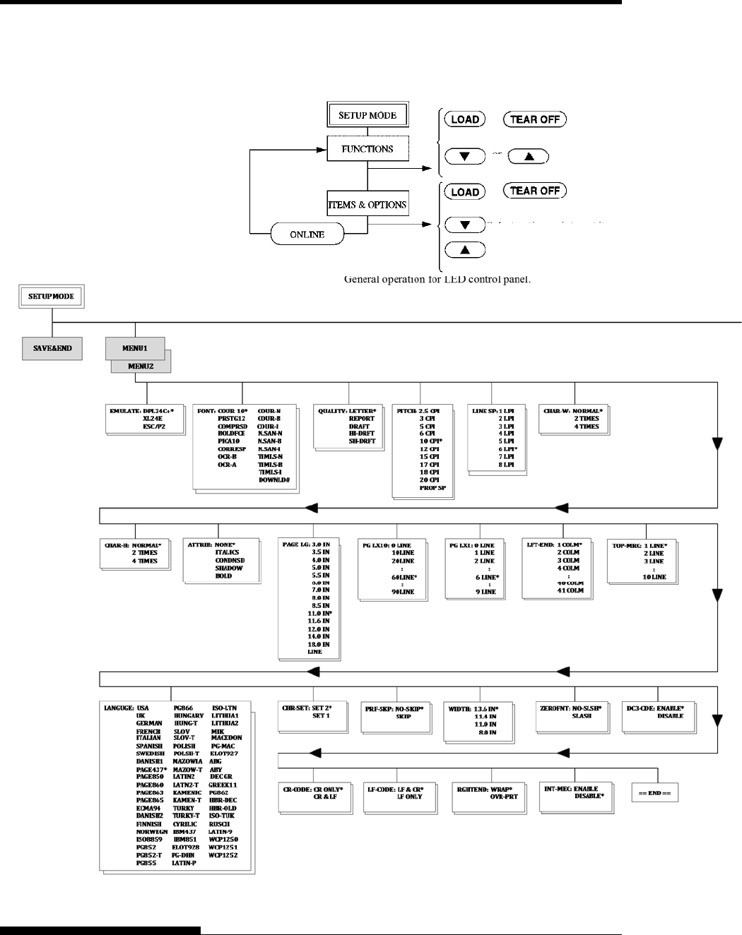
USING SETUP MODE
5-70 User's Manual
DPL24C PLUS ORGANIZATION
Note:
Asterisks (*) indicate default setting at shipment.
or
or
or
Move the cursor on the prime guide.
Select function.
Select option, print next item.
Select option, print previous item.
Move the cursor on the prime guide.
General operation for LED control panel.
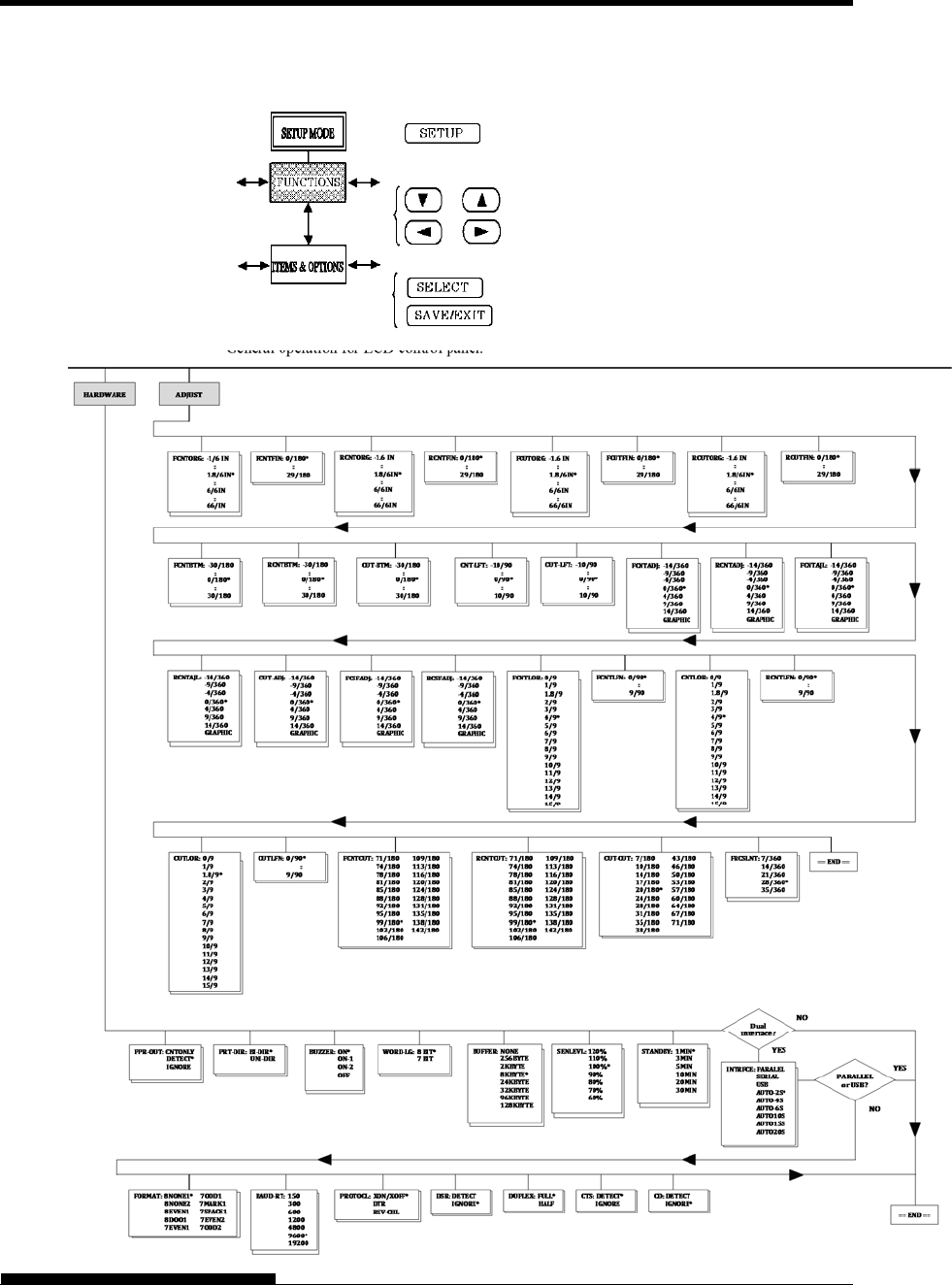
USING SETUP MODE
User's Manual 5-71
To enter SETUP MODE press SETUP at offline state.
Move displaced items
Select the displayed option.
Exit SETUP MODE.
General operation for LCD control panel.
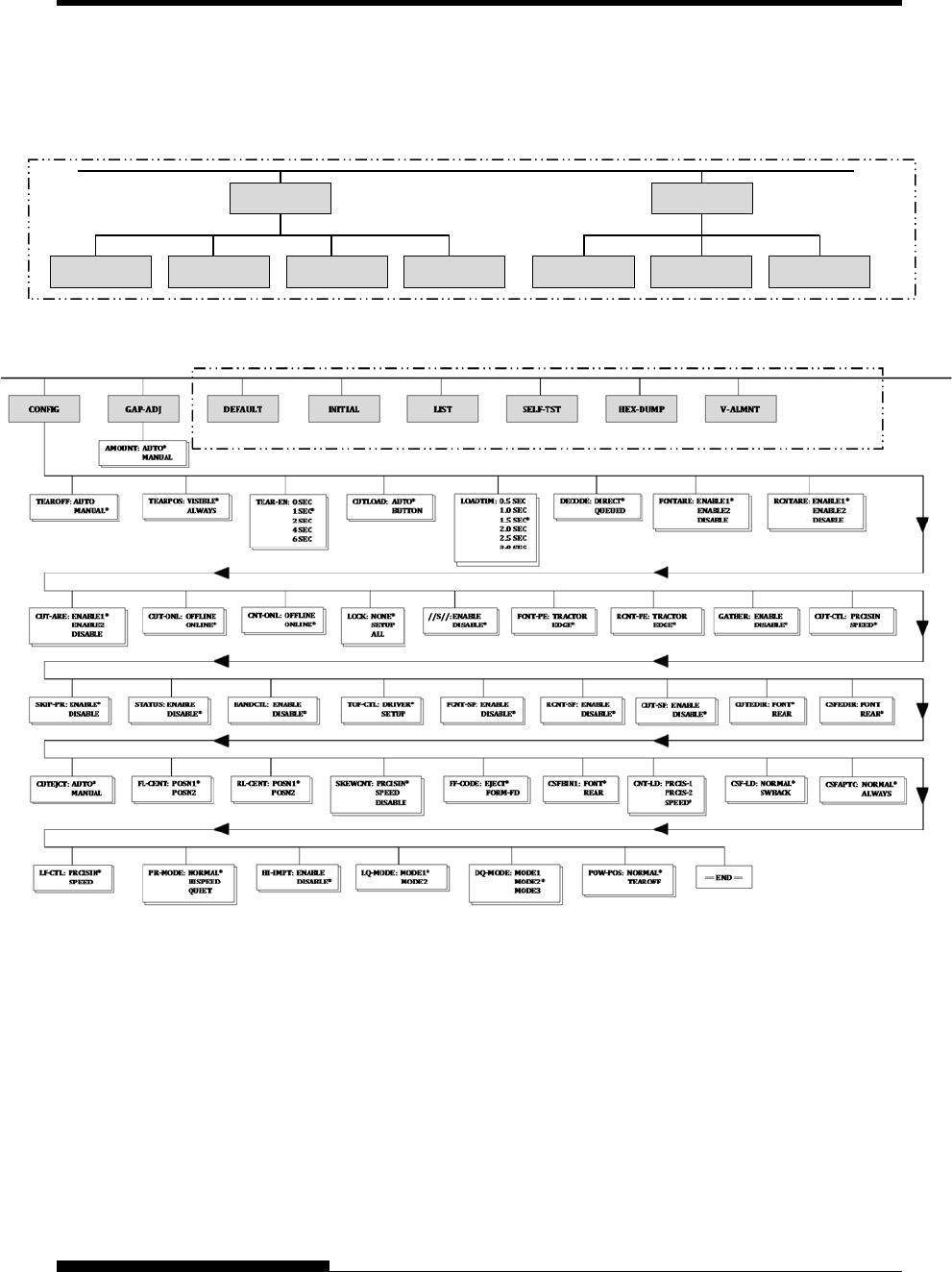
USING SETUP MODE
5-72 User's Manual
This area is only for LED type.
This area is only for LCD type instead of below area.
SUB FUNCTION
SAVE&EXIT LIST DEFAULT INITIAL
SELFDIAGNOSTIC
SELF‐TST HEX‐DUMP V‐ALNMNT
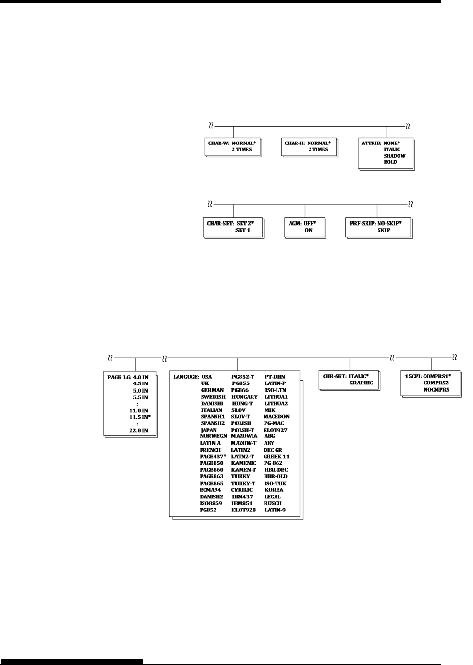
USING SETUP MODE
User's Manual 5-73
Differences in IBM Proprinter XL24E Emulation
In the IBM Proprinter XL24E emulation, MENU1 and MENU2 differ
from the DPL24C PLUS emulation in the following ways:
The following options are different:
The AGM item is provided:
Differences in Epson ESC/P2 Emulation
In the Epson ESC/P2 emulation, MENU1 and MENU2 differ from the
DPL24C PLUS emulation in the following ways:
The LF-CODE item is not defined.
The following options are different:

USING SETUP MODE
5-74 User's Manual
The preceding sections describe offline setup mode. This section
introduces online setup mode. The tedious task of setting up printer
features one-by-one from the control panel and printing and checking the
desired options on paper can be avoided by using online setup mode. In
online setup mode, printer features are set via the computer rather than
the printer control panel.
Put the printer in online setup mode, in either of the following two ways:
Turn the printer off and then turn the printer back on while
pressing the TEAR OFF button. Hold down the button until the
printer beeps.
Issue the printer command ESC e ONLINE. This command is
valid in any emulation.
Send setup data from the computer in any of the following three ways:
Enter setup data directly from the computer keyboard before
starting your job. With MS-DOS, hold down the Ctrl key and
type P. Data entered from the keyboard is sent directly to the
printer. When data entry is complete, hold down the Ctrl key
again and type P. This method is useful when just a few settings
need to be changed.
Use an editor program to prepare a setup data file and then send
the file to the printer using a command before starting your job.
With MS-DOS, use the COPY command. This method is useful
when settings are used repeatedly.
Install a program that enables interactive entry of setup data on
the screen. This method is the most useful of the three. This
printer is provided with a CD which contains this program
called DLMENU. Execute “setup.exe” in Utility folder of CD to
install it.
To exit from online setup mode, send EXIT as the last setup data.
For details of setup data and its format, refer to the programmer’s manual
for each emulation.
ONLINE SETUP
MODE
User's Manual 6-1
6
CHAPTER 6 MAINTENANCE
MAINTENANCE
Your printer requires very little care. Occasional
cleaning and replacement of the ribbon cartridge
are all that is required.
Lubrication of the printer is usually not necessary.
If the print head carriage does not move smoothly back and forth, clean
the printer as described in this chapter. If the problem continues, contact
your dealer to determine whether lubrication might be needed.
The front cover, the rear stacker and the paper table of the printer help
protect against dust, dirt, and other contaminants. However, paper
produces small particles that accumulate inside the printer.
This section explains how to clean and vacuum the printer and how to
clean the platen.
It is easier to clean the printer when the front cover and the rear stacker
are removed.
Cleaning and Vacuuming the Printer
WARNING
To avoid any possibility of injury, before cleaning the
printer, turn off the power to both the printer and the
computer, and unplug the printer.
Use the following procedure to clean and vacuum the printer as required:
1. Remove any paper from the printer. Make sure that the power is
off, and then disconnect the printer power cord.
2. Using a soft vacuum brush, vacuum the exterior of the printer.
Be sure to vacuum the air vents at the front, left sides, and
bottom of the printer. Also vacuum the paper table, rear stacker,
and the cut sheet feeder.
3. Use a soft, damp cloth to wipe the exterior of the printer,
including the cover, paper table, and rear stacker. A mild
detergent may be used.
CAUTION
Do not use solvents, kerosene, or abrasive cleaning materials
that may damage the printer.
CLEANING
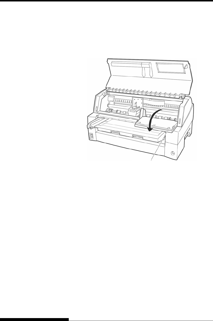
MAINTENANCE
6-2 User's Manual
4. Open the front cover of the printer and remove the ribbon
cartridge. If necessary lay down control panel. Using a soft
vacuum brush, gently vacuum the platen, print head carriage,
and surrounding areas. You can easily slide the print head to the
left or right when the power is off. Be careful not to press too
hard on the flat ribbon cable that extends from the print head
carriage.
Printer interior
5. Re-install the ribbon cartridge. Close the front cover.
6. Raise the soundproof cover or paper table and rear stacker.
Vacuum the forms tractors and surrounding areas.
Cleaning the Platen
Clean the platen about once a month to remove excess ink. Use the
platen cleaner recommended by your supplier and proceed as follows:
1. Apply a small amount of platen cleaner to a soft cloth. Avoid
spilling platen cleaner inside the printer.
CAUTION
Do not use alcohol to clean the platen. Alcohol may cause the
rubber to harden.
2. Place the cloth against the platen.
3. To dry the platen, place a dry cloth against the platen.
Control panel
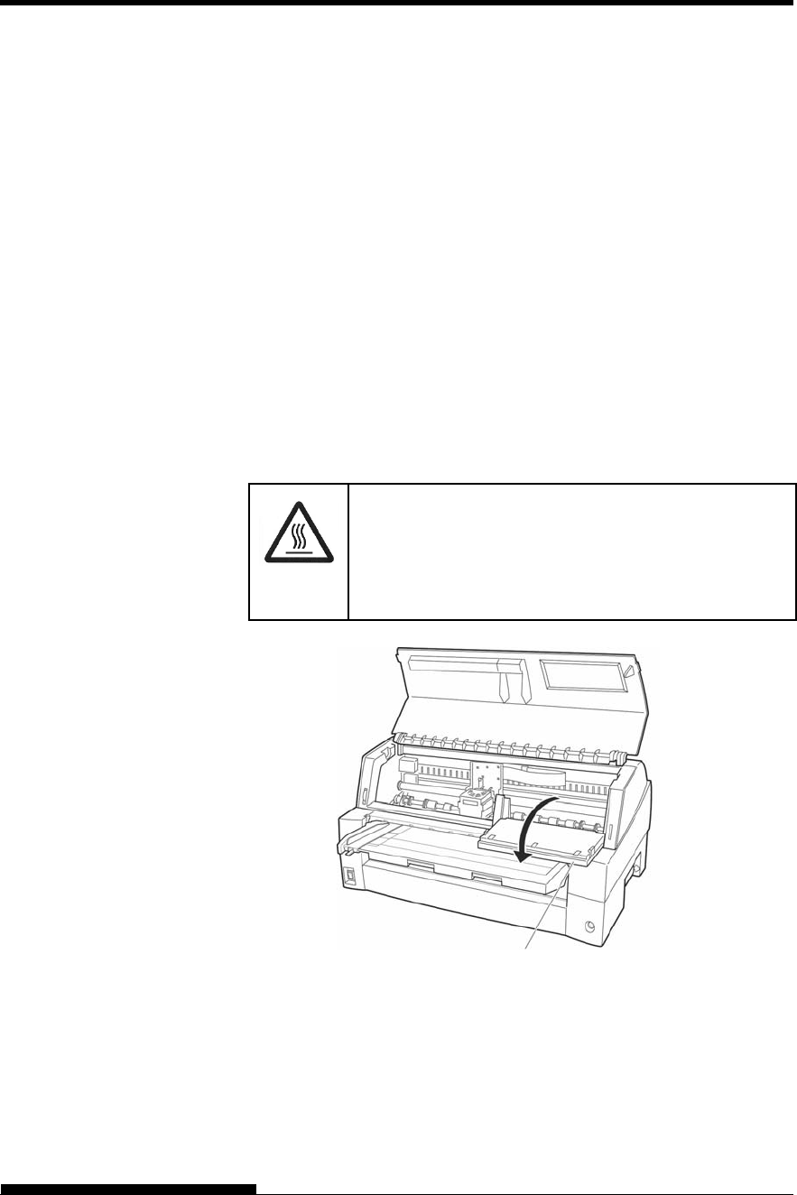
MAINTENANCE
User's Manual 6-3
There are two ways of replacing the ribbon. You can install a new ribbon
cassette in the printer or refill the old ribbon cassette with new ribbon
from a ribbon sub cassette. Appendix A lists order numbers for ribbon
cassettes and ribbon sub cassettes. The following procedure is for ribbon
cassettes. For ribbon sub cassettes, refer to the instructions shipped with
the sub cassette.
To replace the ribbon cassette:
1. Turn off the printer.
Note:
If the power is turned off during or immediately after
printing, turn on the power again. Verify that the print
head has moved to the ribbon replacement position, and
then turn off the power again.
2. Open the front cover and control panel of the printer. Please
make sure that the print head stops at the ribbon replacement
position.
(HOT)
CAUTION <HOT>
The print head and metal frame is hot during printing
or immediately after printing. Do not touch them until
it cools down.
Preparing the printer to install the ribbon cartridge
REPLACING THE
RIBBON
Control
p
anel
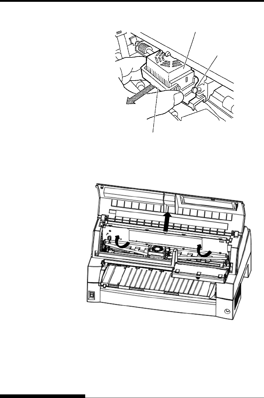
MAINTENANCE
6-4 User's Manual
3. Remove the ribbon guide.
Removing the ribbon guide
4. To remove the ribbon cassette, pull the underside of ribbon
cassette and carefully lift the cartridge out of the printer.
Removing the ribbon cassette
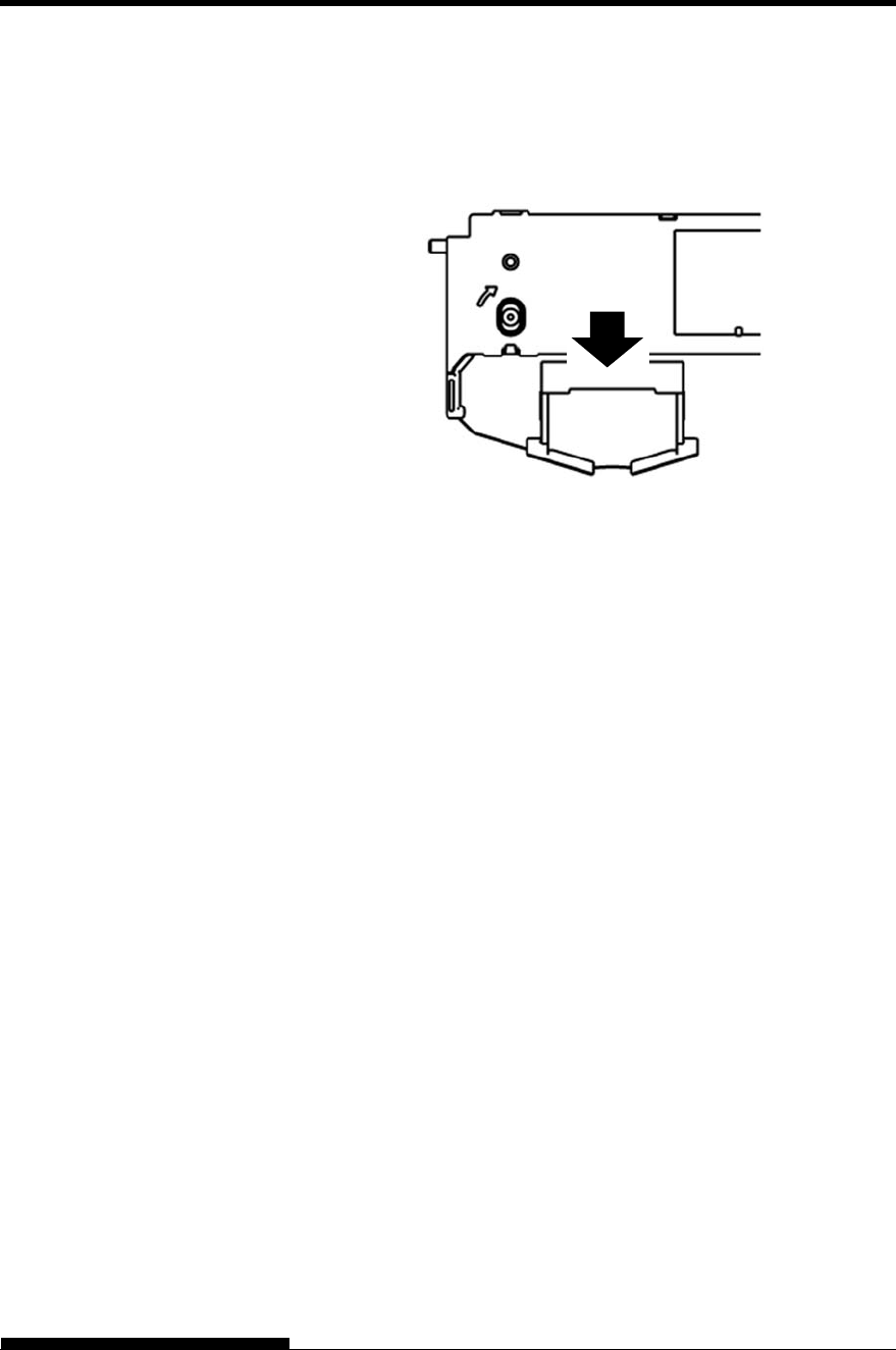
MAINTENANCE
User's Manual 6-5
5. Remove the ribbon guide (green part) from the ribbon cassette.
Don’t turn the ribbon feed knob before installation.
Preparing the ribbon cassette
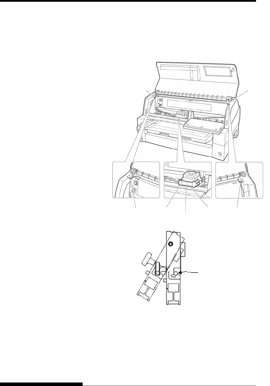
MAINTENANCE
6-6 User's Manual
6. Put the green ribbon guide into the space in front of print head. And
then place the mounting pins (both side of ribbon cassette) on the
slot of the printer cover. And then push the ribbon cassette so that
the ribbon cassette is installed vertically.
Installing the ribbon cassette
Mounting pin
Mounting pin
Ribbon guide
Print head Space Slot
Slot
Push the ribbon cassette until it
clicks.
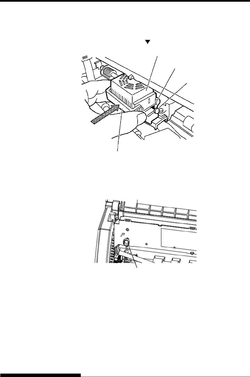
MAINTENANCE
User's Manual 6-7
7. Attach the green ribbon guide on the print head.
Please make sure that the ribbon slack lightly. (If the ribbon is
strained, it will quirk when installation.)Push the green ribbon guide
until the triangle mark” ” meets the round projection of print head.
8. Turn the ribbon feed knob clockwise to take up any slack in the
ribbon.
9. Return the control panel..
10. Close the front cover.
NOTE
A Fujitsu ribbon cassette is recommended. Don’t use other cassettes.
If other cassettes are used, operating problems or a damage of the
print head may be caused.
Triangle mark
Projections
Print Head
Ribbon Guide
Knob
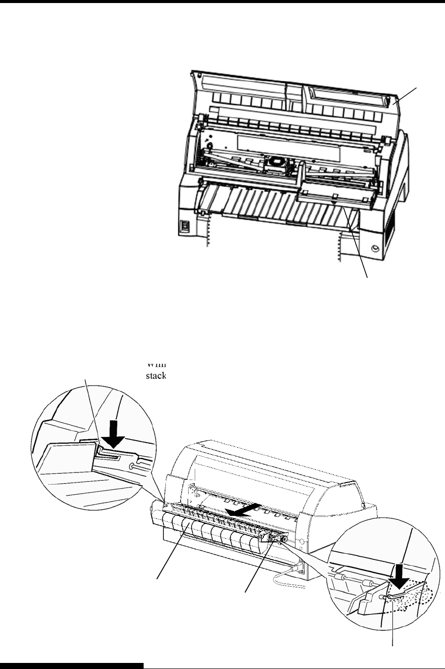
MAINTENANCE
6-8 User's Manual
The control panel of this printer can be pulled down toward the front as
necessary, such as when jammed paper must be removed.
The stacker unit of this printer can be removed in the event that paper is
jammed in it unit.
While pushing down the lock levers of the stacker guide, pull out the
stacker unit from the rear.
OPENING AND
CLOSING THE
CONTROL PANEL
REMOVING THE
STACKER UNIT
Front cover
Control Panel
Stacker guide
Lock lever
Stacker
Lock lever
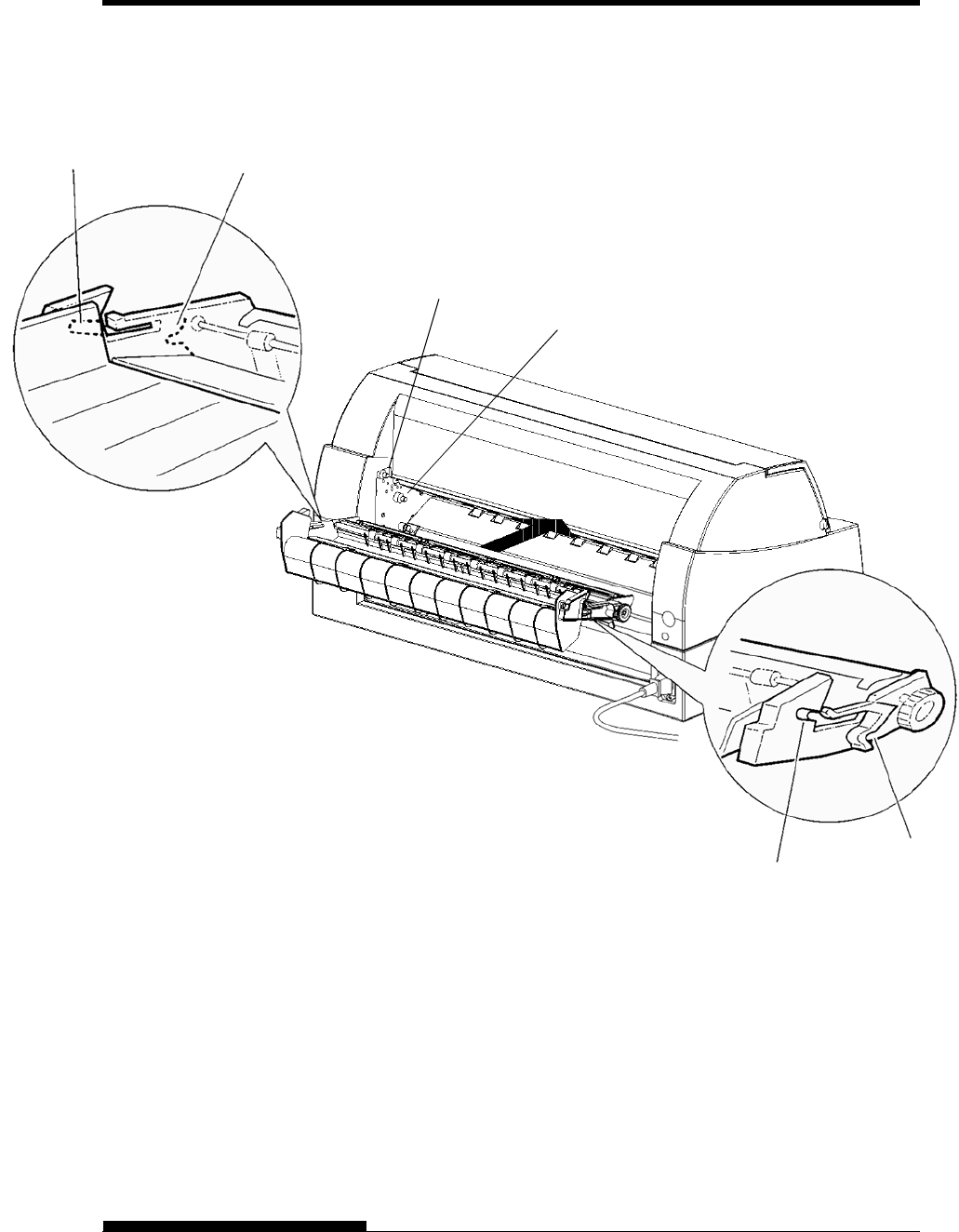
MAINTENANCE
User's Manual 6-9
Position groove 1 over guide pin 1 on the right and left sides of the
stacker unit. Then, push in the stacker unit until guide pin 2 is hooked
onto slot 2.
MOUNTING THE
STACKER UNIT
Guide pin 2
Guide pin 1
Groove 1
Slot 2
Groove 1
Slot 2

User's Manual 7-1
7
CHAPTER 7 TROUBLE-SHOOTING
TROUBLE-SHOOTING
Your printer is extremely reliable, but occasional
problems may occur. You can solve many of
these problems yourself, using this chapter.
If you encounter problems that you cannot resolve,
contact your dealer for assistance.
This chapter is organized as follows:
Solving problems
Diagnostic functions
Getting help
The tables in this section describe common printer problems and their
solutions. The following types of problems are considered:
Print quality problems
Paper handling problems
Operating problems
Printer failures
Print Quality Problems
Poor print quality or other printing problems are often caused by
incorrect printer setup or incorrect software settings. A gradual decrease
in print quality usually indicates a worn ribbon. Table 7.1 identifies
common print quality problems and suggests solutions.
SOLVING
PROBLEMS
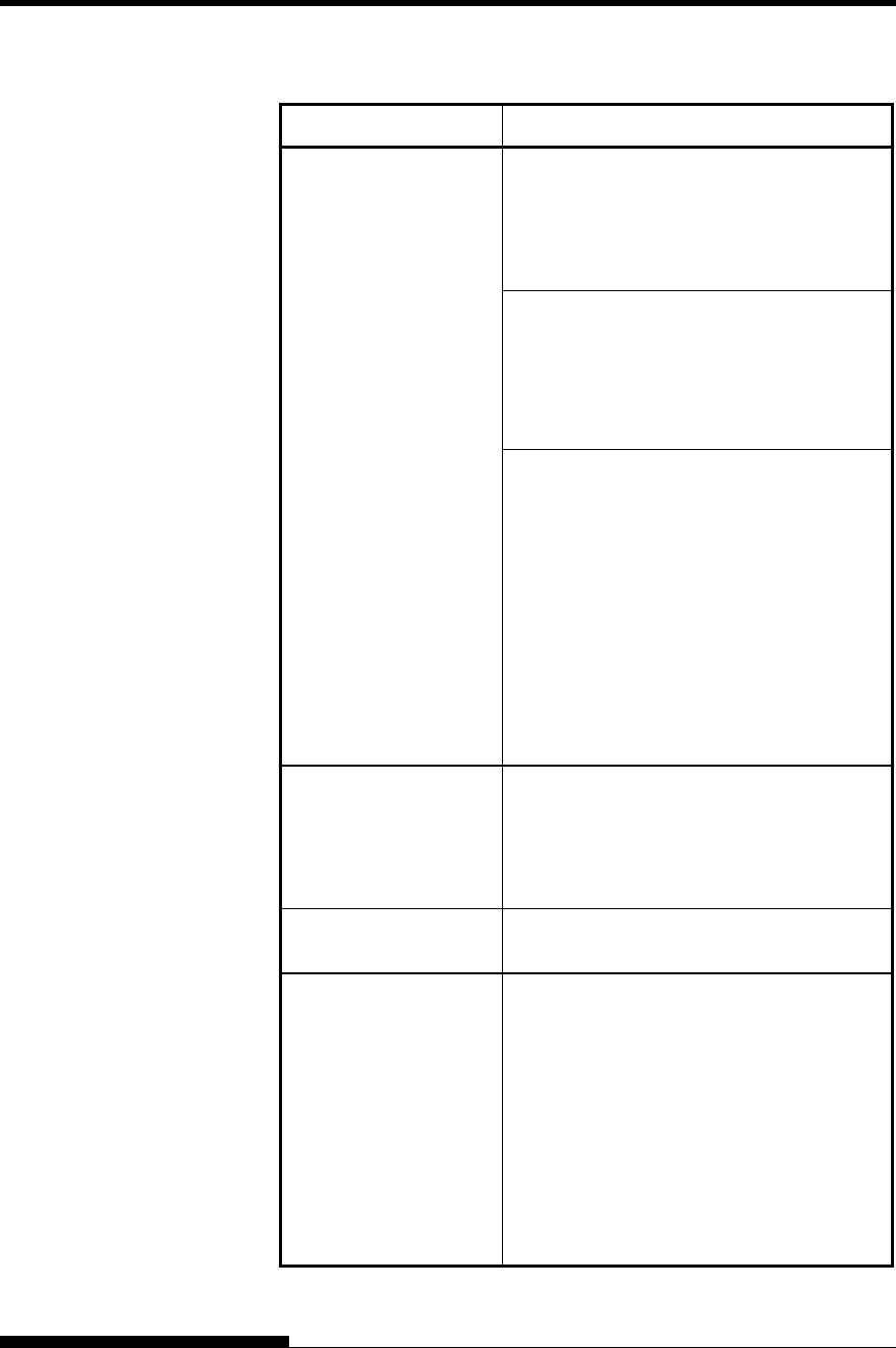
TROUBLE-SHOOTING
7-2 User's Manual
Table 7.1 Print Quality Problems and Solutions
Problem Solution
Printing is too light or
too dark.
Make sure that the ribbon cartridge is
properly installed and that the ribbon feeds
smoothly.
Check ribbon wear. Replace the ribbon if
necessary.
Check the difference of thickness of
medium. If auto adjustment function detects
difference level of medium, it doesn’t work
properly. In this case you must adjust for
paper thickness manually. See ADJUSTING
PAPER THICKNESS in Chapter 3.
If you adjust for paper thickness manually,
tune-up as follows.
If printing is too light, decrease setting.
If printing is dark, increase setting.
Note
Printer accepts the value for paper thickness
from Printer Driver or application program.
In this case, check the setting of the Printer
Driver or application program at your host
computer. And then tune the value by way
above.
Stains or smudges
appear on the page.
Check ribbon wear. Replace the ribbon if
necessary.
Check whether the tip of the print head is
dirty.
Clean the head with a soft cloth if necessary.
The page is blank. Make sure that the ribbon cartridge is
properly installed.
Printing is erratic or the
wrong characters are
printed. One or more
“?” characters are
printed.
Make sure that the interface cable is securely
connected to both the printer and computer.
Make sure that the printer emulation selected
in your software is the same as the emulation
selected on the printer. See the section
Selecting an Emulation in Chapter 2.
If you are using an RS-232C serial interface,
make sure that the serial settings required by
your software or computer are the same as
the settings on the printer. See the section
Hardware Items and Options in Chapter 5.

TROUBLE-SHOOTING
User's Manual 7-3
Table 7.1 Print Quality Problems and Solutions (Cont.)
Problem Solution
Characters are lost at
the left or right end.
If lost area is about 10mm (3mm) from left and
right edge of continuous forms(single sheet),
Area-over detection control woks properly.
In this case make sure that paper size, paper
position, and left and right margins are properly
set.
Note
Preprinted dark color area, shape of corner cut,
paper skew may cause incorrect detection.
Please don’t use medium like this.
If you must use medium like this absolutely,
you can disable Area-over detection by using
setup mode. But risk of print head broken is
increase.
Incorrect paper size selection of the Printer
Driver causes right side area is lost (exactly
Printer Driver divide the page by paper size
setting and postpone divided right page). Please
check the paper size setting.
Printing is vertically
misaligned (jagged).
Use the printer’s V-ALMNT function to check
the vertical print alignment. If necessary, adjust
the print alignment. See the section Using the
Diagnostic Functions in Chapter 5.
Smaller adjustment for paper thickness causes
vertically misalignment too.
Please refer to Printing is too light or too dark.
The top margin is
wrong.
The top margin is the sum of the top-of-form
setting, the software-specified top margin, and
the printer’s TOP-MRG setting. Proceed as
follows:
Make sure that the top-of-form setting is
correct. The factory default is 25.4 mm (1
inch). See the section Changing Top-of
Form in Chapter 5.
Check the software-specified top margin.
Refer to your software documentation.
Check the printer’s TOP-MRG setting. See
the section MENU1 and MENU2 Items
and Options in Chapter 5.
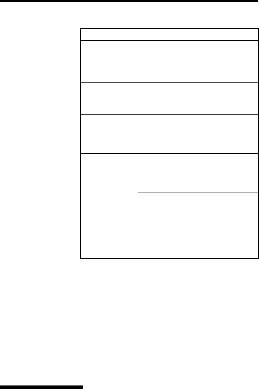
TROUBLE-SHOOTING
7-4 User's Manual
Table 7.1 Print Quality Problems and Solutions (Cont.)
Problem Solution
Lines are double
spaced instead of
single spaced.
Check the line spacing setting in your software.
Change the CR-CODE setting in the printer
setup mode to CR ONLY. See the section
MENU1 and MENU2 Items and Options in
Chapter 5.
The printer
overprints on the
same line.
Change the CR-CODE setting in the printer
setup mode to CR & LF. See the section
MENU1 and MENU2 Items and Options in
Chapter 5.
The next print line
starts where the
previous line ended
instead of at the left
margin.
Change the LF-CODE setting in the printer
setup mode to LF & CR. See the section
MENU1 and MENU2 Items and Options in
Chapter 5.
The top of form of
continuous form
displaces gradually.
Variation of the top of form is saturated in a few
pages and displacement is about 1mm or less. In
this case adjust value is prepared in setup mode.
See ADJUST Items and Options and search
<FCNTADJ> or <RCNTADJ>.
Variation of the top of form isn’t saturated. In
this case setting of page length isn’t correct.
Make sure that page length setting equal actual
page length exactly.
In general page length of continuous form is
multiple of 0.5inch. Anyway don’t set page
length of continuous forms using mm unit.
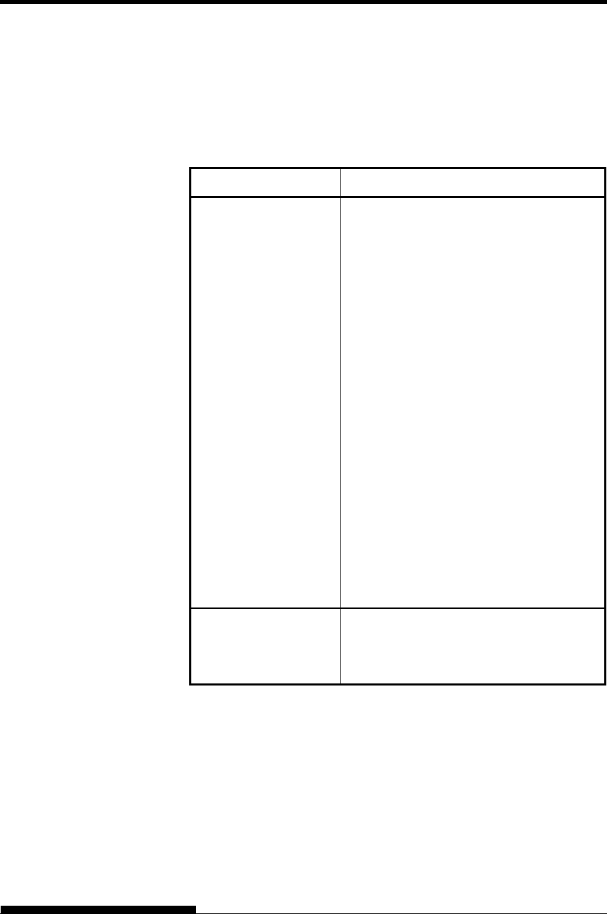
TROUBLE-SHOOTING
User's Manual 7-5
Paper Handling Problems
Table 7.2 describes common paper handling problems and suggests
solutions. See Chapter 3 for detailed procedures on loading and using
paper.
Table 7.2 Paper Handling Problems and Solutions
Problem Solution
Paper cannot be loaded
or fed.
Make sure that the paper path indicator
(FRONT TRACTOR, REAR TRACTOR,
CUT SHEET) lights correctly.
Press the PAPER PATH button to select the
paper path.
Make sure that the paper covers the paper-
out sensor, i.e., the left paper edge is within
52 mm for single sheets or 41 mm for
continuous forms from the left edge of the
platen. (This problem cannot occur if you
use the forms tractor unit or insert a single
sheet with its left edge in contact
with the left paper guide.)
Make sure that the tractor unit is correctly
installed and that the tractor shaft gear
engages the platen shaft gear.
If you are using a cut sheet feeder, make
sure that the bin lever is set to the
“CLOSED” position. (The bin lever is on the
left side of the feeder.)
If you are using a cut sheet feeder, make
sure that the feeder is firmly mounted on the
printer and the cable is correctly connected.
Paper manually loaded
is ejected without
printing
If you are using the paper skew detection
(option), adjust the paper guide on the paper
table for the print start position and correctly
slide the sheet along the guide.
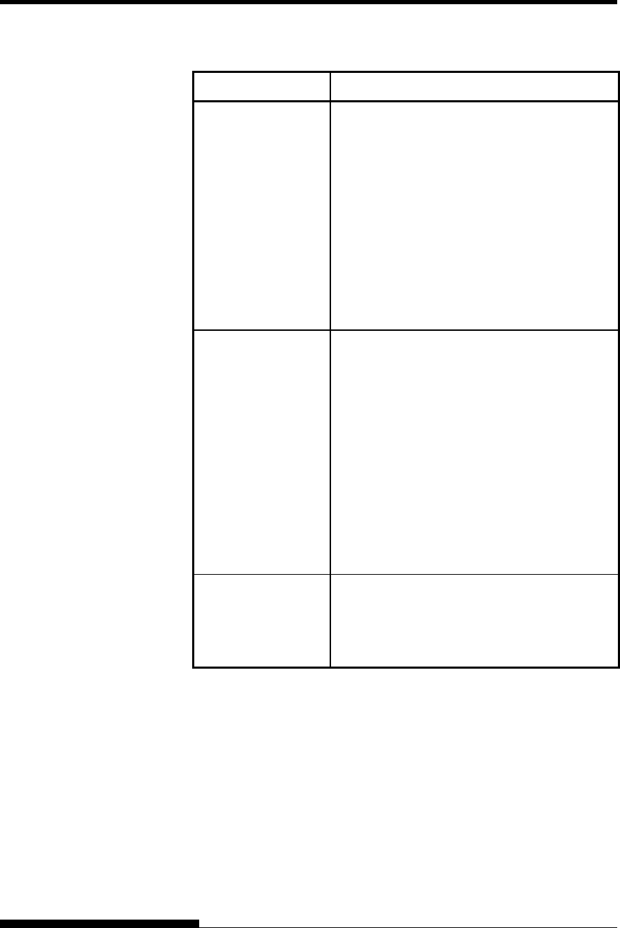
TROUBLE-SHOOTING
7-6 User's Manual
Table 7.2 Paper Handling Problems and Solutions (Cont.)
Problem Solution
Paper jams while
loading.
Turn off the printer and remove the jammed
paper. Remove any obstructions from the paper
path.
If you are using a cut sheet feeder, make sure
that the bin lever is set to the “CLOSED”
position. (The bin lever is on the left side of the
feeder.)
Make sure that the paper is not folded, creased,
or torn.
Reload the paper.
Make sure that the paper table is in normal
mode. Set the paper table to normal mode.
Paper jams while
printing.
Turn off the printer and remove the jammed
paper. Remove any obstructions from the paper
path.
For continuous forms, make sure that the
incoming and outgoing paper stacks are
correctly placed. Paper should feed straight.
Make sure that the paper table is in normal
mode. Set the paper table to normal mode.
If you are using a cut sheet feeder, make sure
that the bin lever is set to the “CLOSED”
position. (The bin lever is on the left side of the
feeder.)
Reload the paper.
Paper slips off the
forms tractors or the
perforated holes of
the paper tear during
printing.
Make sure that the forms tractors are positioned
correctly for the width of your paper and that
the perforated holes of the paper fit directly over
the tractor sprockets.
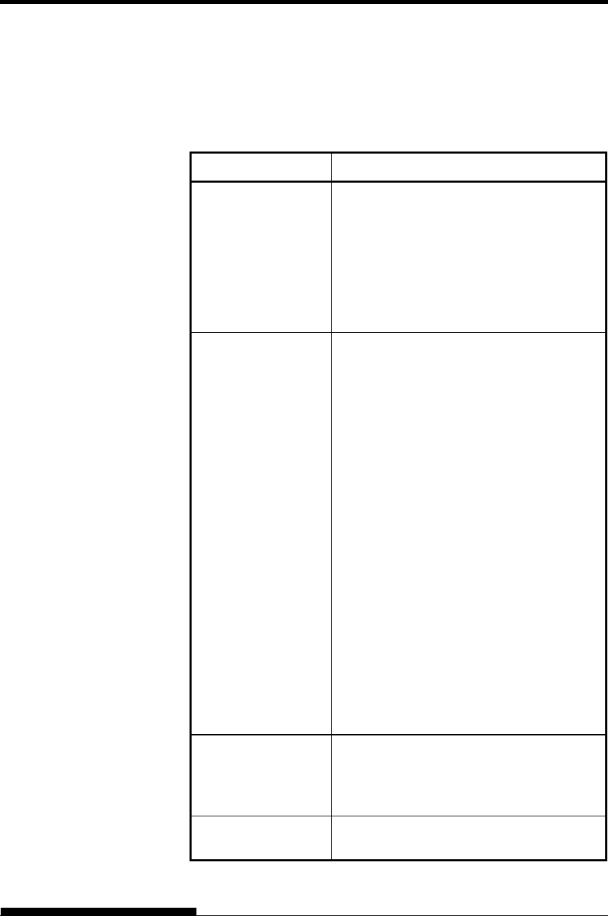
TROUBLE-SHOOTING
User's Manual 7-7
Operating Problems
Table 7.3 identifies common operating problems and suggests solutions.
If you cannot resolve a problem, contact your dealer.
Table 7.3 Operating Problems and Solutions
Problem Solution
The power does not
turn on.
Make sure that the “I” on the printer power
switch is depressed.
Make sure that the power cord is securely
connected to both the printer and the outlet.
Make sure that the power outlet is functional.
Turn the power off. Wait 100 seconds and
then turn the printer on again. If the printer
still has no power, contact your dealer.
The printer is on but it
will not print.
Make sure that the printer is online.
Make sure that the interface cable is securely
connected to both the printer and the
computer.
If the red PAPER OUT indicator is lit, load
paper.
Run the printer self-test (see Chapter 5). If the
self-test executes normally, the problem is
caused by the interface, the computer,
incorrect printer settings, or incorrect software
settings.
Make sure that the printer emulation selected
in your software is the same as the emulation
selected on the printer. See the section
Selecting an Emulation in Chapter 2.
Make sure that the front cover is completely
closed.
If you are using an RS-232C serial interface,
make sure that the serial settings required by
your software or computer are the same as the
settings on the printer. See the section
Hardware Items and Options in Chapter 5.
The cut sheet feeder
does not operate.
Make sure that the cut sheet feeder is firmly
mounted on the printer.
Make sure that the cable is correctly
connected.
The FRONT DIR
indicator blinks.
Remove the printed sheet of paper from the
paper table.

TROUBLE-SHOOTING
7-8 User's Manual
Printer Failures
A user cannot generally resolve a problem involving defective printer
hardware. On detecting a fatal error, the printer will:
Stop printing
Beep four times
Turn the ONLINE indicator off
The control panel displays alarms. The meanings of alarms can be
checked in the following table.
TROUBLE-SHOOTING
User's Manual 7-9
Alarm display function(LED)
This printer has a function for distinguishing between alarms by using
the blinking of individual lamps on the control panel.
From the combination of blinking lamps in an alarm state, the meaning
of the alarm can be determined as shown in the following table.
Lamp
Alarm name
PAPER OUT
REMOVE PAPER
FRONT DIR
QUIET
HI SPEED
AUTO GAP
HI IMPACT
TRACTOR F
TRACTOR R
CUT SHEET
MENU1
MENU2
ONLINE
Condition of occurrence
LRES alarm
LRES could not be detected during the
space initial operation.
Space problem alarm
The shield board could not be detected
normally by the LRES sensor.
Fan alarm
The cooling fan could not rotate.
Fire check alarm
SP motor
Abnormally high current of motor driver
was detected.
Fire check alarm
Ribbon motor
Abnormally high current of motor driver
was detected.
Ribbon jam alarm
Detect the jam of the ribbon.
Detect the ribbons other than the genuine
product
HCPP (cut sheet or
continuous forms paper
switching) alarm
Switching between cut sheet paper and
continuous forms paper was not possible.
Fire check alarm
LF motor
Abnormally high current of motor driver
was detected.
Fire check alarm
CSF motor
Abnormally high current of motor driver
was detected.
Overload alarm
An overload occurred during printing, and
second pass printing was performed.
However, the power source voltage was
not restored.
Low voltage alarm
The power source voltage dropped below
the specified level when no printing was in
progress.
Fire check alarm
Print Head
Abnormally long driving of print head
driver was detected.
Over voltage alarm
Over voltage of power source was
detected.
APTC gap alarm
During the APTC operation, paper was
detected immediately after the start of
approach motion, or no paper was
detected.
APTC home position
sensor alarm
During the APTC operation, no reference
position was detected.
ROM/RAM alarm
A sum-check error or read/write error
occurred, or no CG-ROM is mounted.
: Blinking
Blank: Off
TROUBLE-SHOOTING
7-10 User's Manual
Alarm display function(LCD)
This printer has a function for distinguishing between alarms by using
the blinking of message lamp and LCD on the control panel.
Alarm name
Message Lamp
LCD Condition of occurrence
LRES alarm FATAL!
LRES ALARM
LRES could not be detected during the space initial operation.
Space problem alarm FATAL!
SPACE ALARM
The shield board could not be detected normally by the LRES sensor.
Fan alarm FATAL!
FAN ALARM
The cooling fan could not rotate.
Fire check alarm
SP motor
FATAL!
SPM ALARM
Abnormally high current of motor driver was detected.
Fire check alarm
Ribbon motor
FATAL!
RBFM ALARM
Abnormally high current of motor driver was detected.
HCPP (cut sheet or continuous
forms paper switching) alarm
FATAL!
HCPP ALARM
Switching between cut sheet paper and continuous forms paper was
not possible.
Fire check alarm
LF motor
FATAL!
LFM ALARM
Abnormally high current of motor driver was detected.
Fire check alarm
CSF motor
FATAL!
CSFM ALARM
Abnormally high current of motor driver was detected.
Overload alarm FATAL!
OVERLOAD ALARM
An overload occurred during printing, and tripartite printing was
performed. However, the power source voltage was not restored.
Low voltage alarm FATAL!
LOW VOLT ALARM
The power source voltage dropped below the specified level when no
printing was in progress.
Fire check alarm
Print Head
FATAL!
HEAD ALARM
Abnormally long driving of print head driver was detected.
High voltage alarm FATAL!
HIGH VOLT ALARM
Over voltage of power source was detected.
APTC gap alarm FATAL!
APTC GAP ALARM
During the APTC operation, paper was detected immediately after
the start of approach motion, or no paper was detected.
APTC home position sensor
alarm
FATAL!
APTC HPS ALARM
During the APTC operation, no reference position was detected.
Ribbon jam alarm FATAL!
RIBBON JAM ALARM
Detect the jam of the ribbon.
Detect the ribbons other than the genuine product
ROM/RAM alarm FATAL!
ROM/RAM ALARM
A sum-check error or read/write error occurred, or no CG-ROM is
mounted.
: Blinking
Blank: Off
TROUBLE-SHOOTING
User's Manual 7-11
Responses to alarm occurrences
Your first response to each alarm should be as described in the following
table.
Problem Solution
LRES alarm Remove any paper dust, which may cause problems
in carriage operation.
Space problem
alarm
Same solution same as above should be done.
Check adjustment for paper thickness.
Smaller setting causes spacing problem.
Fan alarm Remove any dust of ventilation near the Fan motor.
APTC gap
alarm
Check the paper thickness (0.04 to 0.65 mm).
Check whether the paper has different thicknesses
or whether the paper has filing holes.
For problems other than the above, request your printer dealer to make
repairs.
Especially Fire Check is happen, please refrain using printer.
The printer diagnostic functions are SELF-TST, HEX-DUMP, and V-
ALMNT.
SELF-TST tells you whether the printer hardware is functioning
correctly. If the printer hardware is functional, any problems
you are having are probably caused by incorrect printer settings,
incorrect software settings, the interface, or the computer.
HEX-DUMP allows you to determine whether the computer is
sending the correct commands to the printer, and whether the
printer is executing the commands correctly. This function is
useful to programmers or others who understand how to
interpret hex dumps.
V-ALMNT allows you to check and, if necessary, correct the
printer’s vertical print alignment.
For details on using these functions, all of which are available in the
printer setup mode, see the section Using the Diagnostic Functions in
Chapter 5.
DIAGNOSTIC
FUNCTIONS

TROUBLE-SHOOTING
7-12 User's Manual
If you are not able to correct a problem using this chapter, contact
your dealer for assistance. Be prepared to provide the following
information:
Your printer model number, serial number, and date of
manufacture. Look for this information on the rating label at the
back of the printer.
Description of the problem
Type of interface you are using
Names of your software packages
List of the printer default settings. To print the default settings,
see the section Printing a List of Selected Options in Chapter
5.
GETTING HELP
User's Manual 8-1
8
CHAPTER 8 INSTALLING OPTIONS
INSTALLING OPTIONS
The installation of options allows you to expand
the capabilities of your printer. Options available
for the printer include:
LAN card
Cut sheet feeder
Tractor unit
Large stacker
Small paper table
Sound proof cover
The LAN card is a user installable option, but can be installed only on a
printer model with the parallel and USB interfaces. For information on
the installation procedure, refer to the manual that comes with the LAN
card.
Options can be purchased from your dealer. Order numbers for options
are given in Appendix A.
This section explains how to install the LAN card.
WARNING (Electric shock)
Before mounting or removing the LAN card, turn off
the power switches of the personal computer and the
printer and remove the power plug from the outlet.
Otherwise, you may receive electric shock.
1. Turn the power off.
Make sure that the power switch is set to the “○”side, and make
sure that a power plug is disconnected from an outlet.
INSTALLING THE
LAN card
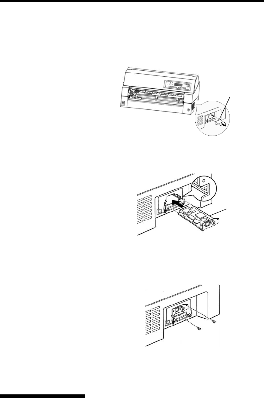
INSTALLING OPTIONS
8-2 User's Manual
2. Remove metal plate
Remove two screws and metal plate on the parallel port.
Keep metal plate removed.
3. Insert LAN card
Insert the LAN card along both sides of guide rails slowly.
Make sure that LAN card is inserted all the way into the slot.
4. Tighten the LAN card
Tighten the LAN card with two screws removed in step 2.
LAN cable
Metal plate
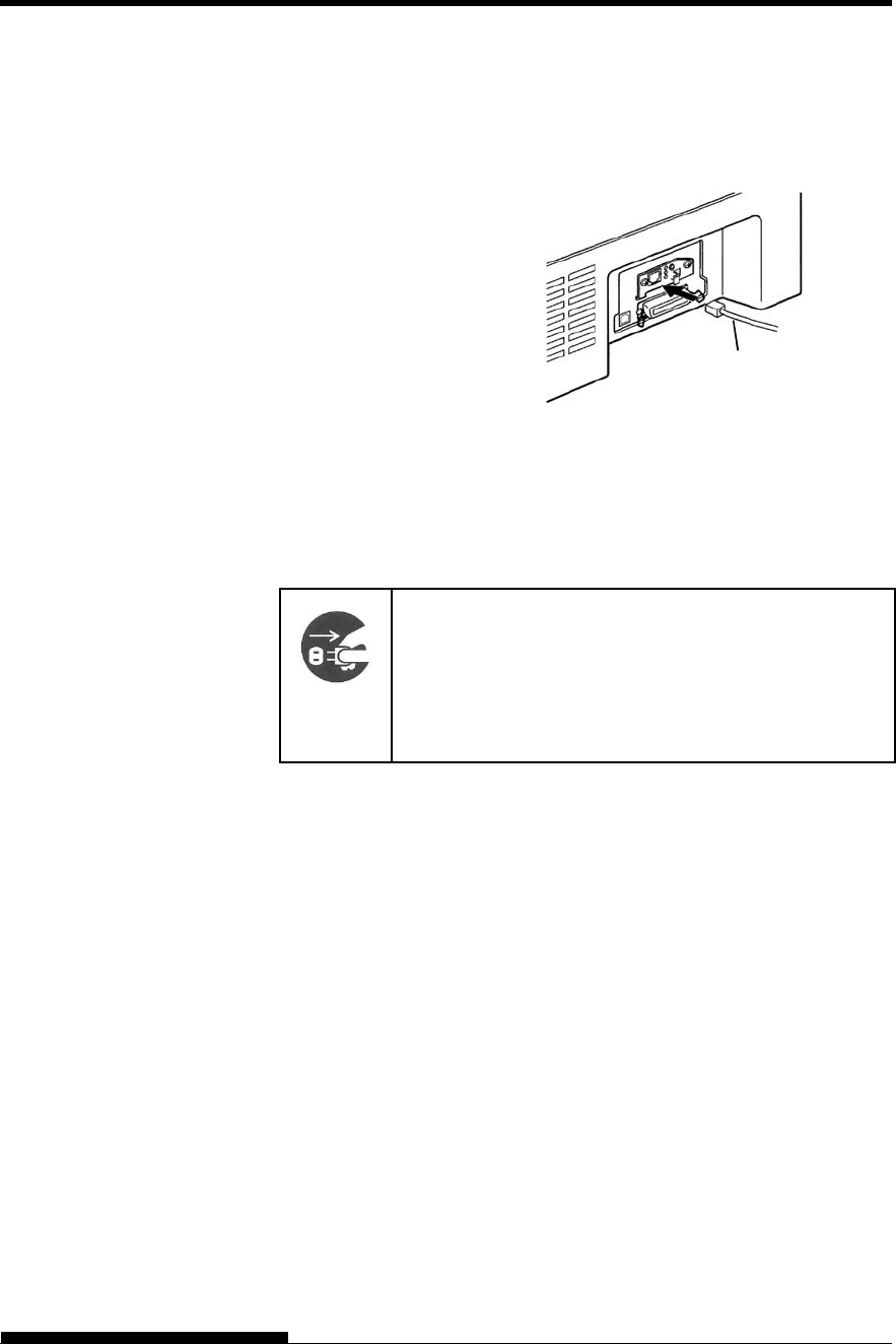
INSTALLING OPTIONS
User's Manual 8-3
5. Connect LAN cable
After tightening LAN card, connect LAN cable first, then the
power plug.
Please refer to the manual attached to LAN card about LAN
card setting.
This chapter describes what to do after installing cut sheet feeder.
WARNING (Electric shock)
Before mounting or removing the cut sheet feeder, turn
off the power switches of the personal computer and
the printer and remove the power plug from the outlet.
Otherwise, you may receive electric shock.
A cut sheet feeder (SF940) allows you to automatically feed single sheets.
It can be mounted on the front or the rear of the printer.
When attaching the cut sheet feeder to the rear of the printer, replacing
the stacker with large stacker is necessary (See “INSTALLING THE
LARGE STACKER” on page 8-9).
For both front and rear, the cut sheet feeder can handle a max. of 5-ply
multipart media.
When installing the front and rear cut sheet feeders, the printer assigns
the first bin to the front feeder. You can change the assignment using set
up mode.
Installing on the front side of the printer
1. Turn off the printer power.
Confirm that the printer power is turned to the side.
2. Removing the tractor unit
INSTALLING THE
CUT SHEET
FEEDER
LAN cable
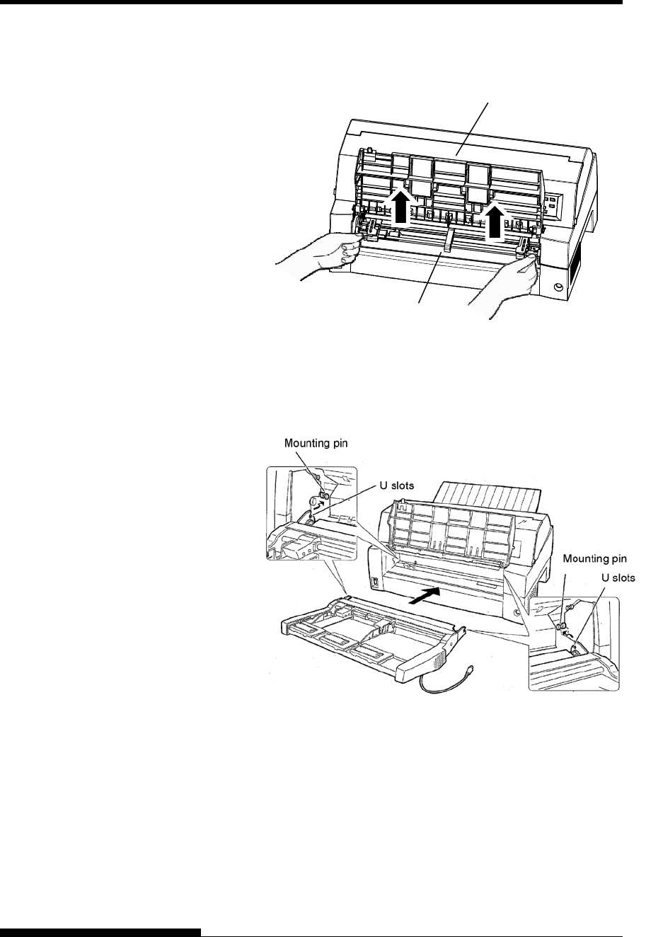
INSTALLING OPTIONS
8-4 User's Manual
Raise the paper table and remove the tractor unit. (For details
on mounting and removing the tractor unit, see “Selecting the
Tractor Unit Position” on page 2-10.)
3. Installing the cut sheet feeder
Adjust the U slots made on both sides of the cut sheet feeder to
the mounting pins inside the printer and lower the cut sheet
feeder slowly.
Check that the cut sheet feeder frame is correctly mounted on
mounting pin 2.
Paper table
tractor unit
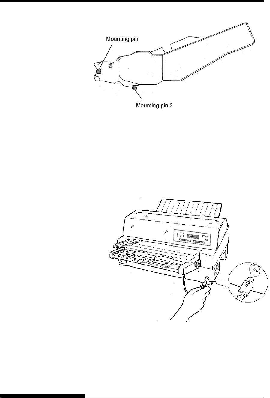
INSTALLING OPTIONS
User's Manual 8-5
4. Replacing the paper table
Be sure to replace the paper table. (Same way as “Close the
paper table” on page 2-6.)
If the paper table is incorrectly set, a paper jam may occur.
5. Connecting the cable
Connect the cut sheet feeder cable to the connector on the front
right of the printer. Insert the cable with the connector arrow
mark up.
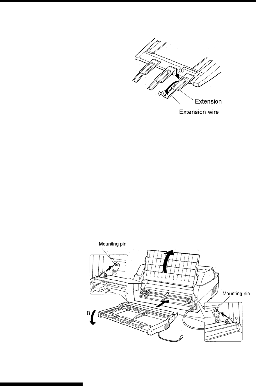
INSTALLING OPTIONS
8-6 User's Manual
6. Extend the extension and extension wire in the order from
(1) to (2) according to the size of the paper to be used.
Installing on the rear side of the printer
Before mounting the cut sheet feeder, turn off the printer power.
1. Turn off the printer power.
Confirm that the printer power is turned to the O side.
2. Installing the cut sheet feeder
Open the rear stacker. Hold both sides of the cut sheet feeder
and adjust the U slots made on both side of the cut sheet feeder
to the mounting pins inside the printer. (Attach the slots with
the letter A of the cut sheet feeder adjusted to that on the printer
side.) Then, lower the cut sheet feeder like it turns in the
direction of arrow B, using the mounting pins as supporting
points.
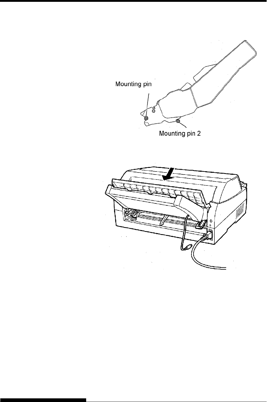
INSTALLING OPTIONS
User's Manual 8-7
Check that the cut sheet feeder frame is correctly mounted on
mounting pin 2.
3. Close the rear stacker.
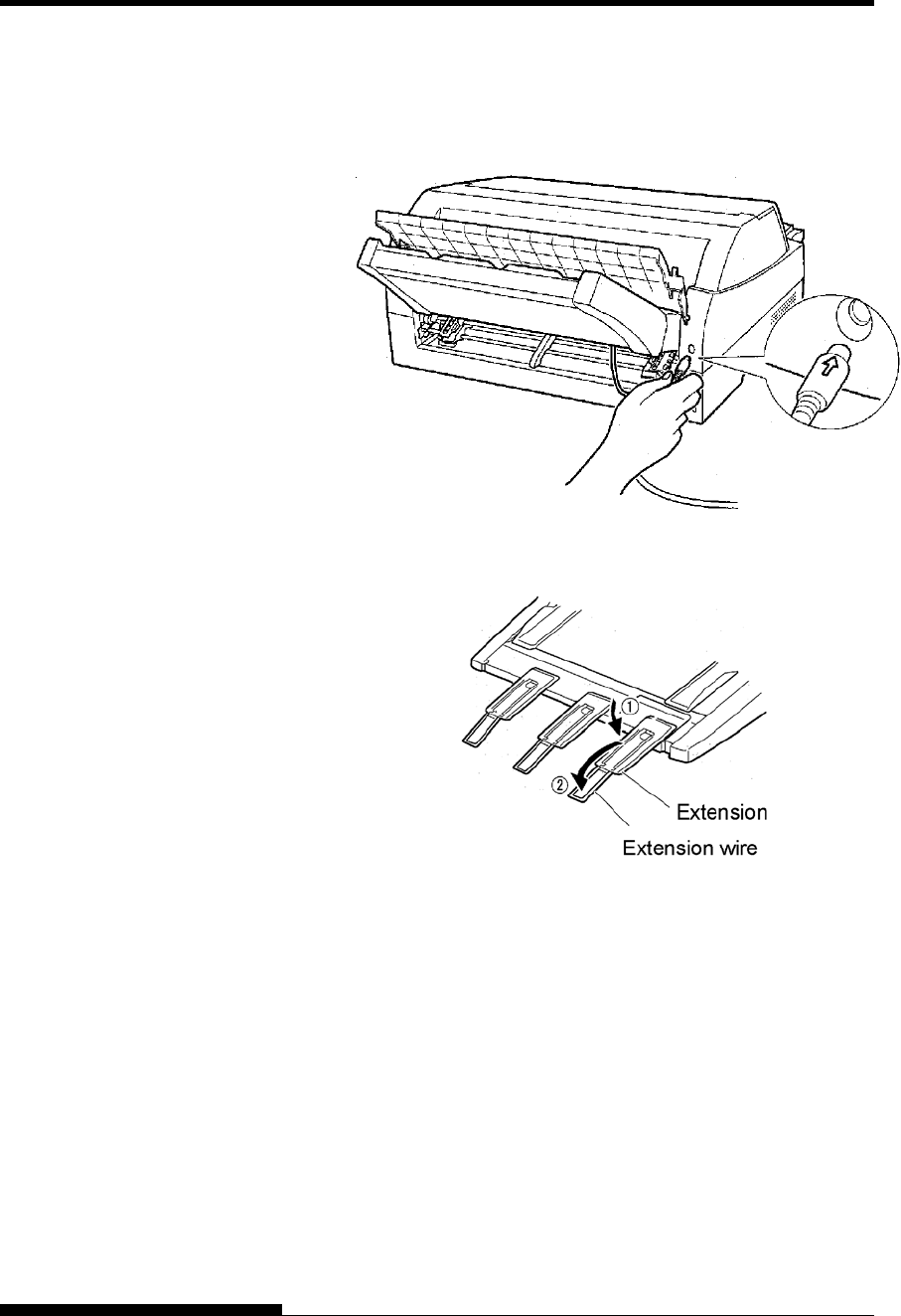
INSTALLING OPTIONS
8-8 User's Manual
4. Connecting the cable
Connect the cut sheet feeder cable to the connector on the rear
right of the printer. Insert the cable with the connector arrow
mark up.
5. Extend the extension and extension wire in the order from
(1) to (2) according to the size of the paper to be used
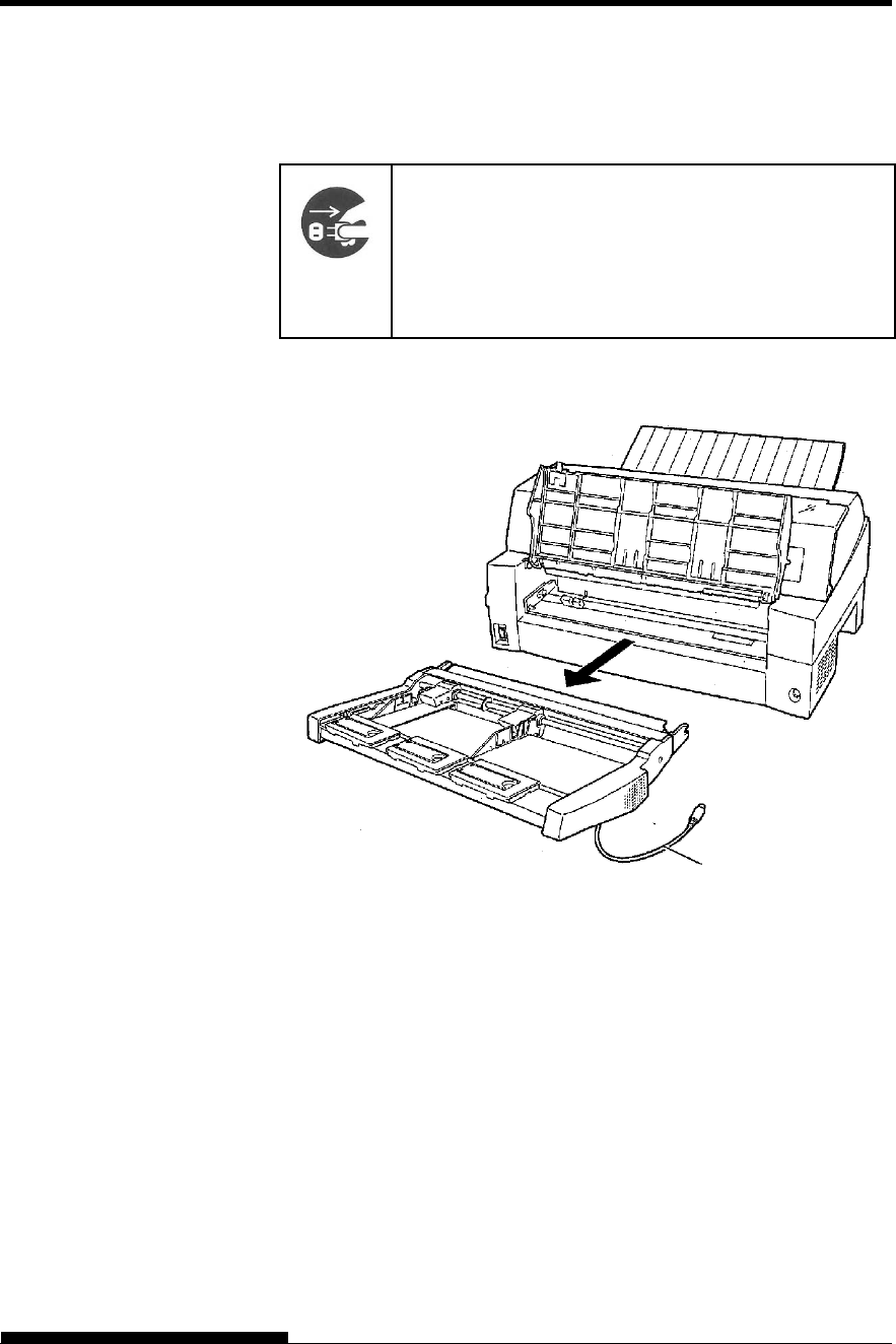
INSTALLING OPTIONS
User's Manual 8-9
Removing the Cut Sheet Feeder
Before removing the cut sheet feeder, disconnect the cable.
WARNING (Electric shock)
Before mounting or removing the cut sheet feeder, turn
off the power switches of the personal computer and
the printer and remove the power plug from the outlet.
Otherwise, you may receive electric shock.
When mounted on the front side of the printer
Cable
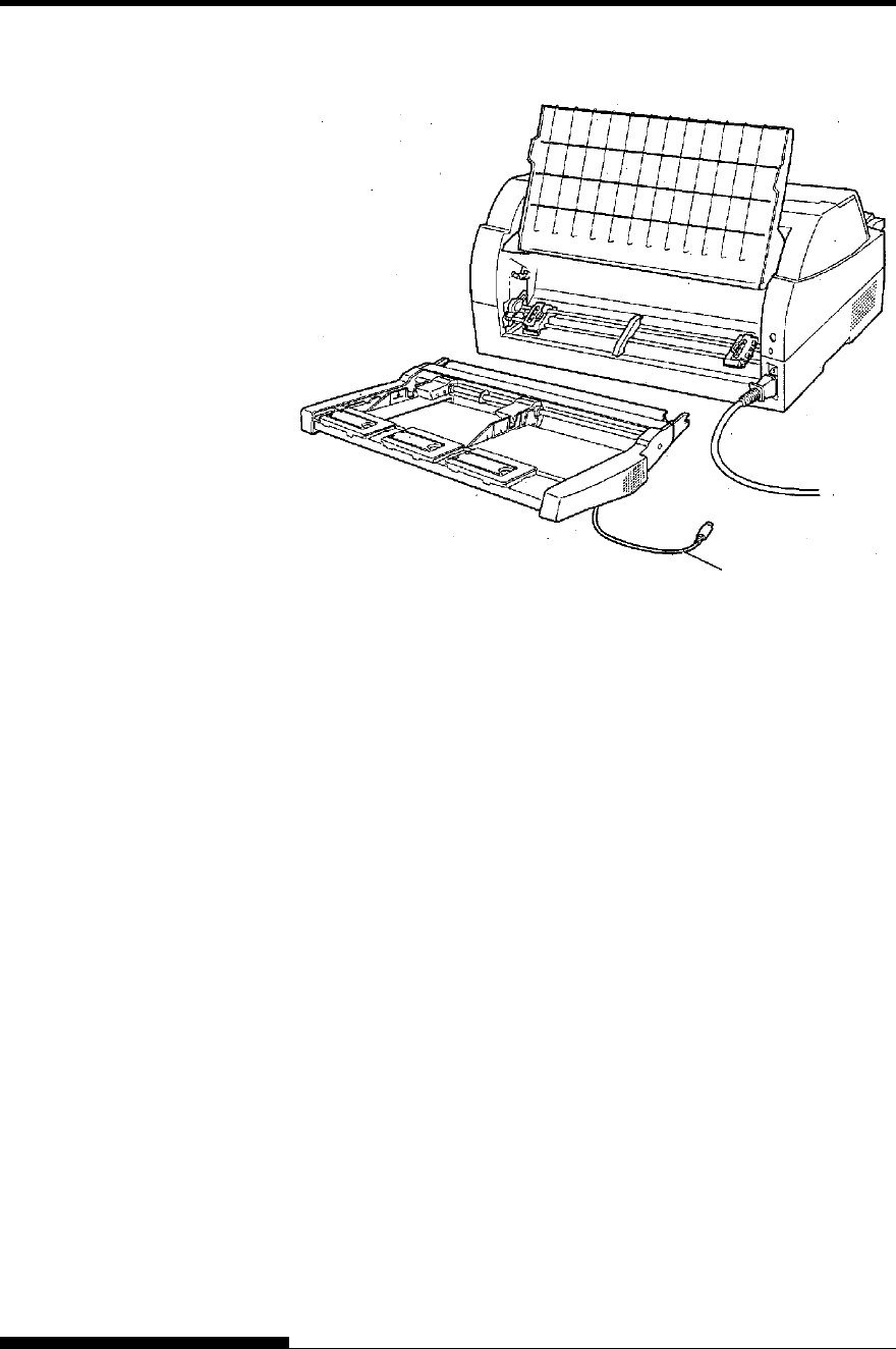
INSTALLING OPTIONS
8-10 User's Manual
When mounted on the rear side of the printer
A tractor unit is supplied as standard equipment attached to the front of
the printer.
This unit may also be attached to the rear of the printer for rear feeding
of continuous forms.
For details on removing and mounting the tractor unit, see “Mounting
and removing the Tractor unit” on page 2-10.
INSTALLING THE
TRACTOR UNIT
Cable
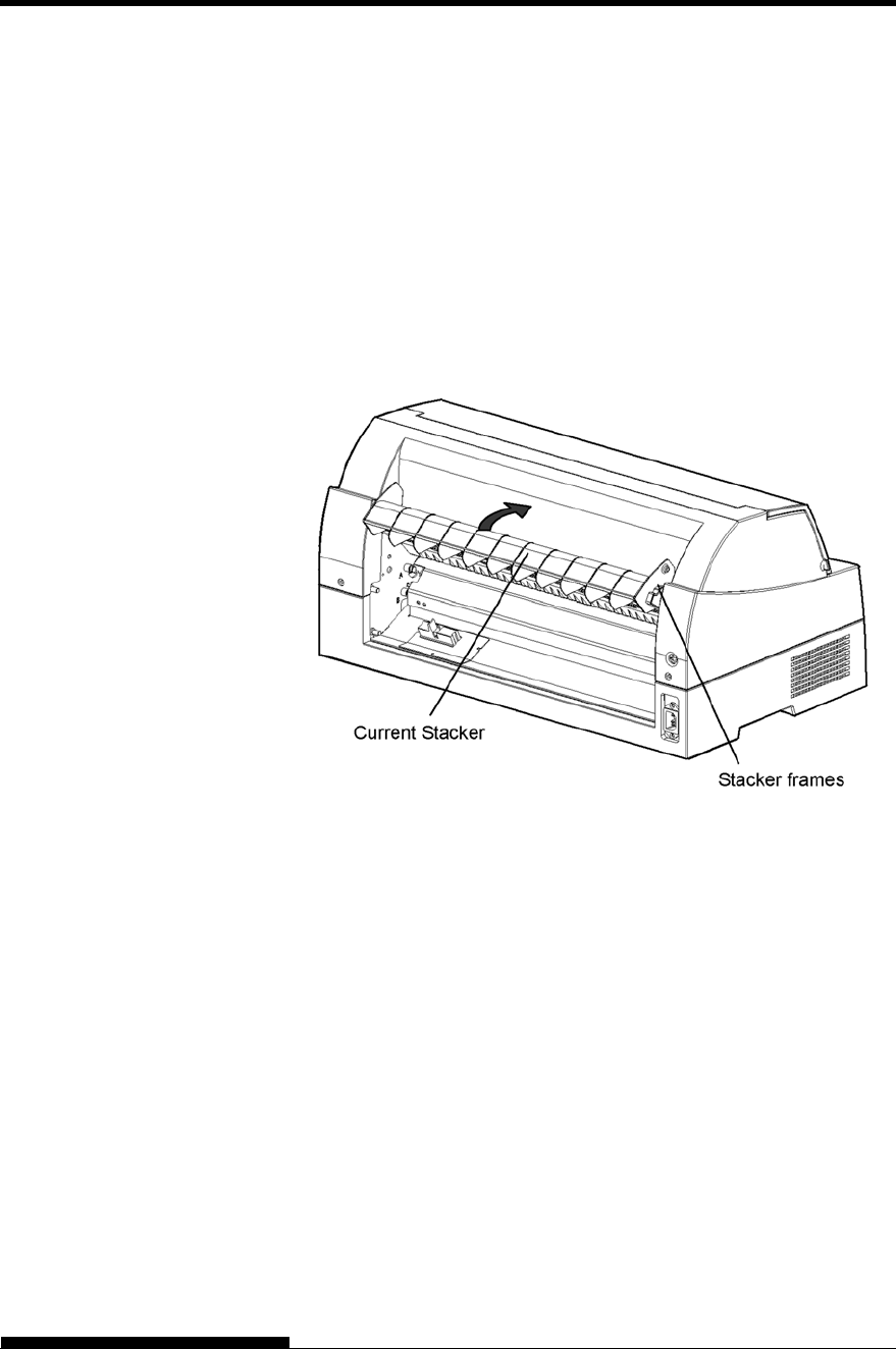
INSTALLING OPTIONS
User's Manual 8-11
To stack cut sheets continuously or eject long cut sheets to the rear,
mount the large stacker.
Also, if a cut sheet feeder is mounted at the rear, the stacker must be
replaced with the large stacker even if cut sheets need not be
continuously stacked.
1
Removing the current stacker
1. Lift up the current stacker in the direction indicated by the arrow.
2. With the stacker in the condition described in step 1, push out
the right and left stacker frames to separate them from the
protrusions on the stacker plate.
INSTALLING THE
LARGE STACKER
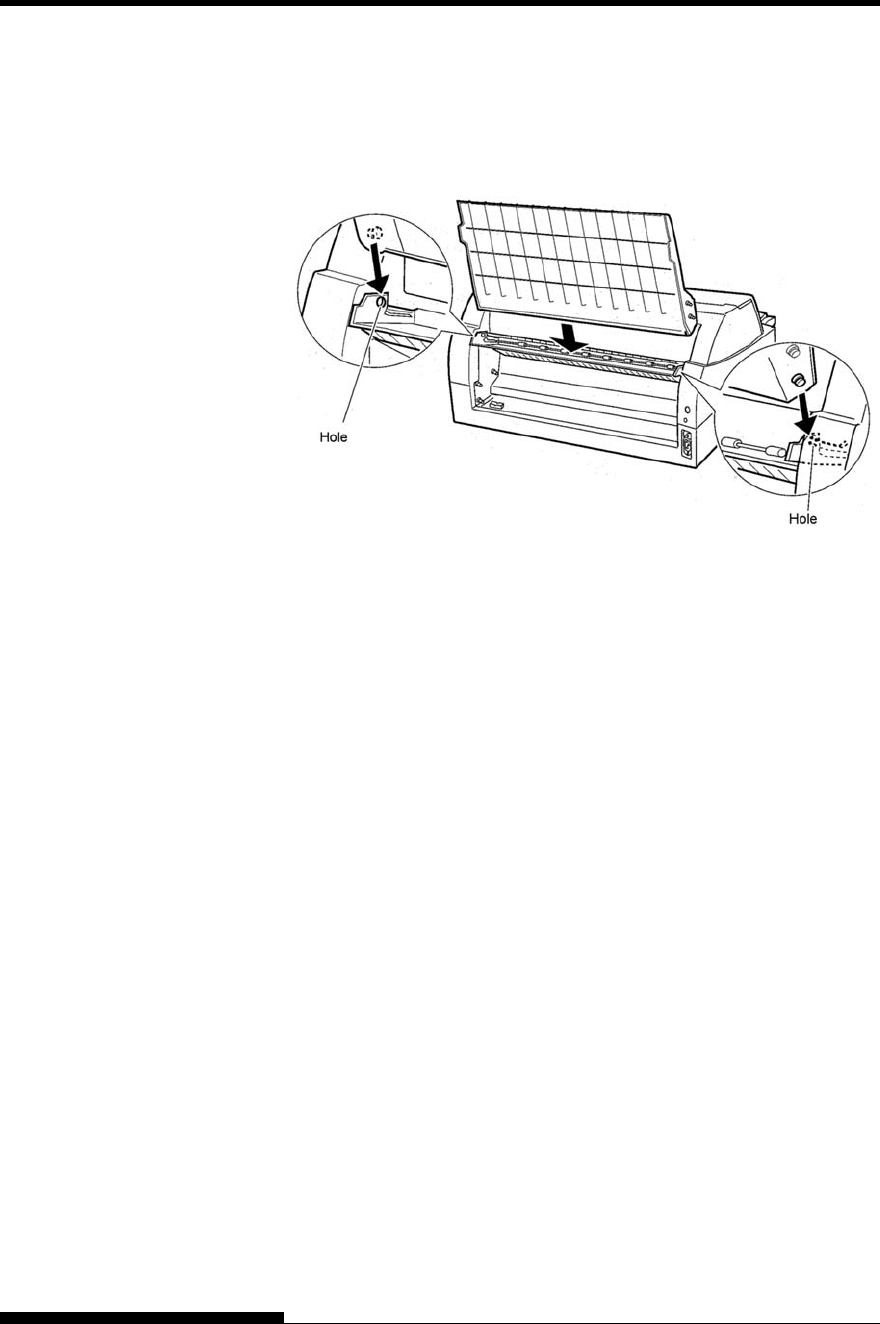
INSTALLING OPTIONS
8-12 User's Manual
2
Mounting the rear stacker
At the rear of the printer, push the protrusions on both sides of the
rear stacker into the holes inside the rear stacker guide as shown in
the following figure.
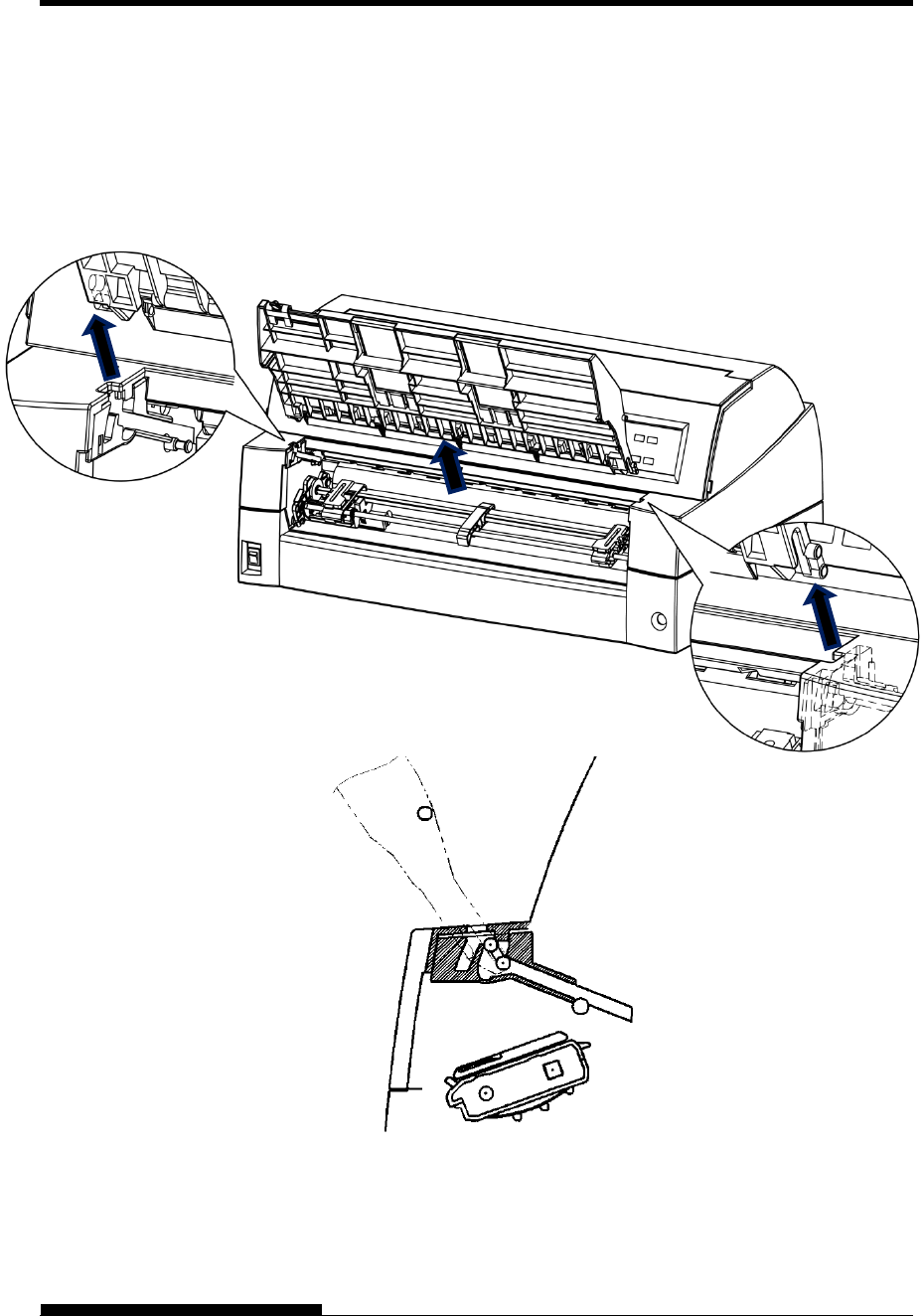
INSTALLING OPTIONS
User's Manual 8-13
Please install it when you use only a short cut sheet.
1 Removing the current paper table
After opening the paper table and adjusting it to a tilted position,
remove the paper table by pulling it to separate the left and right
protrusions on the paper table ends from the grooves on the cover.
INSTALLING THE
SMALL PAPER
TABLE
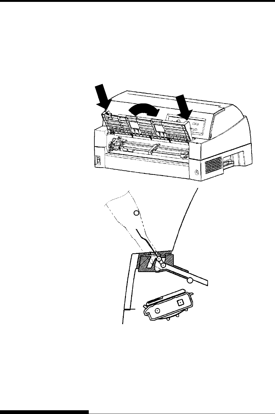
INSTALLING OPTIONS
8-14 User's Manual
2 Installing the Small Paper Table
Insert and push the left and right protrusions on the paper table ends
into the grooves on the cover as shown in the following figure. Set
the paper table in the normal position. (See “Setting the paper table”
in Chapter 2.)
The paper table can be opened or closed in the same way as the
removed current paper table.
Make sure the protrusions
are inserted completely as
left figure.
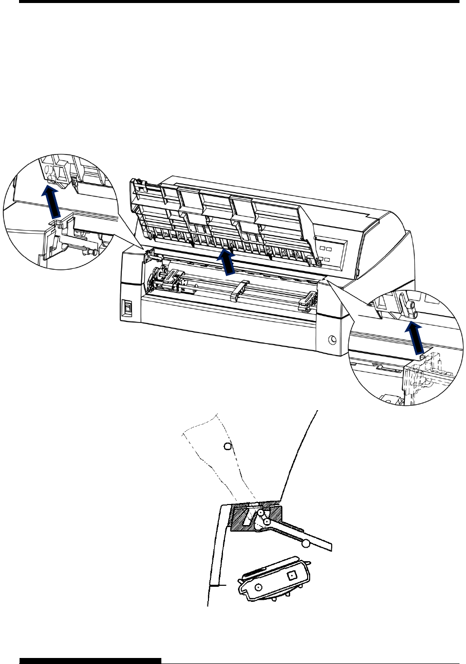
INSTALLING OPTIONS
User's Manual 8-15
The Acoustic noise can be decreased by installing Sound proof cover.
However, the cut sheet and Cut Sheet Feeder cannot be used.
1 Removing the current paper table
After opening the paper table and adjusting it to a tilted position,
remove the paper table by pulling it to separate the left and right
protrusions on the paper table ends from the grooves on the cover.
INSTALLING THE
SOUND PROOF
COVER
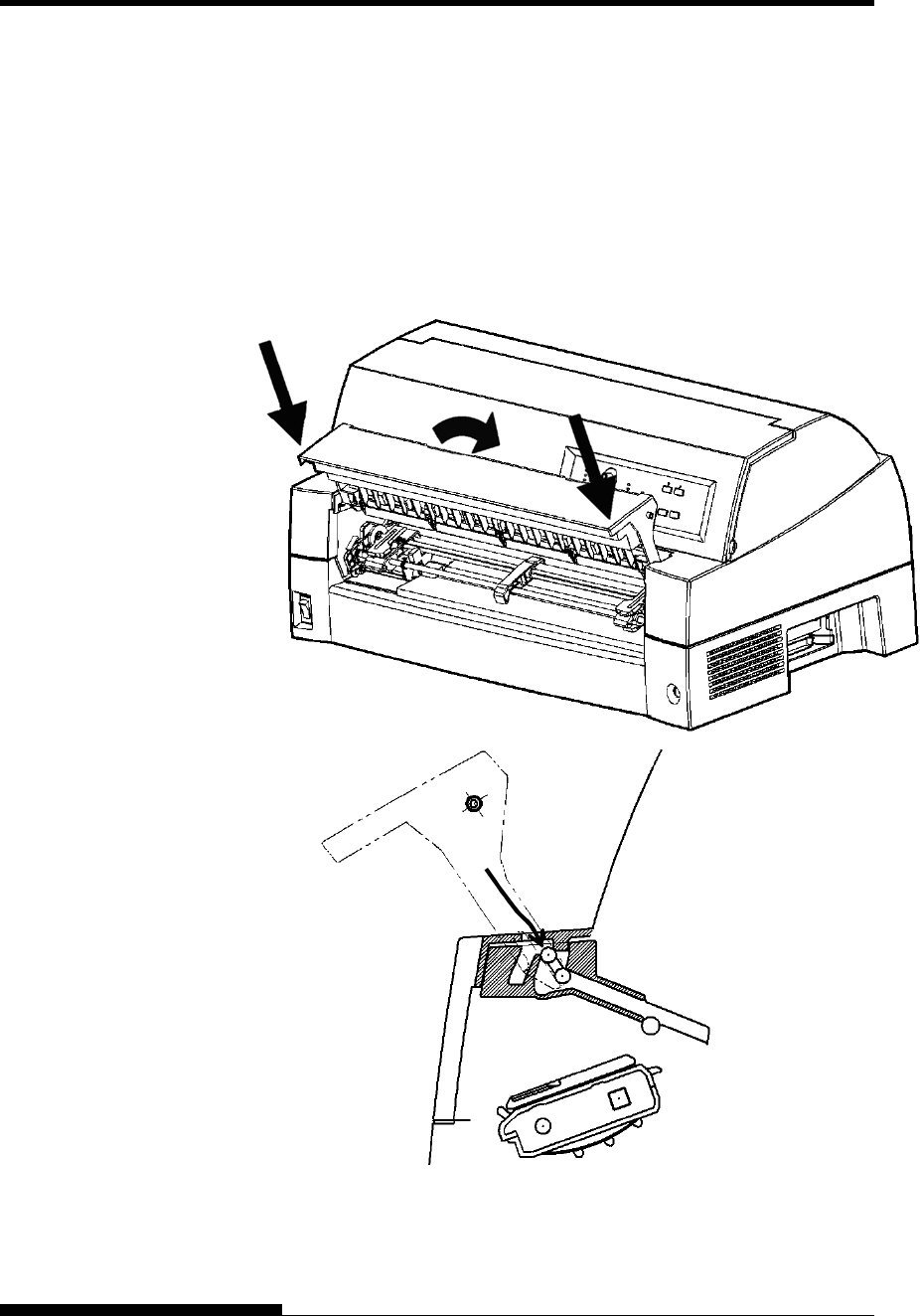
INSTALLING OPTIONS
8-16 User's Manual
2
Installing the Sound Proof Cover
Insert and push the left and right protrusions on the paper table ends
into the grooves on the cover as shown in the following figure. Set
the paper table in the normal position. (See “Setting the paper table”
in Chapter 2.)
The paper table can be opened or closed in the same way as the
removed current paper table.
Make sure the protrusions
are inserted completely as
left figure.
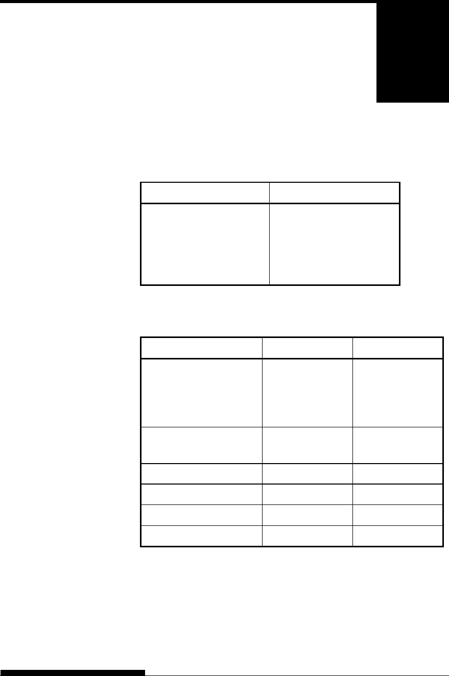
User's Manual A-1
A
APPENDIX A SUPPLIES AND OPTIONS
SUPPLIES AND OPTIONS
This appendix lists the supplies and options available
for the printer.
Contact your dealer for information on ordering
any of these items.
Supplies Order Number
Ribbon cassette
Black ribbon KA02087-D811
Ribbon sub cassette
Black ribbon KA02087-D881
Options Order Number Description
LAN card KA02086-C130 Installable only on
a printer model
with the parallel
and USB
interfaces.
Cut sheet feeder
(SF940)
KA02027-D750
Tractor Unit KA02038-E650
Large Stacker KA02086-D160
Small paper table KA02086-D170
Sound proof cover KA02086-D190
SUPPLIES
OPTIONS

User's Manual B-1
B
APPENDIX B PRINTER AND PAPER SPECIFICATIONS
PRINTER AND PAPER
SPECIFICATIONS
This appendix gives the physical, functional, and
performance specifications for the printer.
It also gives detailed paper specifications.
Dimensions
Height: 290 mm (11.4 in)
Width: 600 mm (23.6 in)
Depth: 350 mm (13.8 in)
Weight: 22.5 kg (50 lb)
AC power requirements
M33335A: 100 to 120 V ±10%; 50/60 Hz
M33335B: 220 to 240 V ±10%; 50/60 Hz
Power consumption
Model:M33335A
Average 485 VA
Maximum 820 VA
Standby 1W
Model:M33335B
Average 360 VA
Maximum 810 VA
Standby 1W
Heat generation Average 980 kJ/h
Interface Centronics parallel and RS-232C serial
Centronics parallel and USB and LAN (option).
Data buffer size 0, 256, 2K, 8K, 24K, 32K, 96K, or 128K bytes
Download buffer Maximum 128K bytes
(128K minus data buffer size)
Operating environment 5 to 38°C (41 to 100°F)
30% to 80% RH (no condensation)
Wet bulb temperature, less than 29°C (84°F)
Storage environment -15 to 60°C (-4 to 140°F)
10% to 95% RH (no condensation)
Acoustic noise Standard model :Average 59 dB (A)
Install sound proof cover : Average 55 dB (A)
PHYSICAL
SPECIFICATIONS

PRINTER AND PAPER SPECIFICATIONS
B-2 User's Manual
ISO 7779 (Bystander Position-Front)
(Letter MODE 2)

PRINTER AND PAPER SPECIFICATIONS
User's Manual B-3
Print method Impact dot matrix with a 0.21 mm or 0.25mm,
24-wire head
Print direction Bidirectional logic-seeking or unidirectional
seeking
Character cell Horizontal vertical
Letter (10 cpi): 36 24 dots
Letter (12 cpi): 30 24 dots
Report: 18 24 dots
Draft: 9 24 dots (MODE 1)
12 24 dots (MODE 2)
High-speed draft: 9 24 dots
Paper handling
Standard: Friction-feed platen (cut sheets)
Convertible bi-directional tractor on front or
rear
Paper loading by LOAD button Advancing
perforations to tear-off edge by TEAR OFF
button
Parking continuous forms is available.
Optional: Cut sheet feeder(for front or rear)
Tractor unit (for 2nd tractor)
Paper type 1 to 5-copies for cut sheet feeder
1 to 9-copies for tractor and paper table
Paper size
Continuous Width: 102-420 mm (4-16.5 in)
Length: 102 mm (4 in) or greater
Cut sheets
(Paper table)
Width: 55-420 mm (2.16-16.5 in)
Length: 70-420 mm (2.76-16.5 in)
(Cut sheet feeder)
Width: 100-420 mm (4-16.5 in)
Length: 70-420 mm for front cut sheet feeder
(2.76-16.5 in)
100-420 mm for front cut sheet feeder
(4-16.5 in)
Note:
To use cut sheets exceeding 297 mm in length, the optional large
large stacker is
FUNCTIONAL
SPECIFICATIONS

PRINTER AND PAPER SPECIFICATIONS
B-4 User's Manual
required. For detail see Chapter 3.
Paper thickness Up to 0.65 mm (0.026 inch)
Page length
By software Programmable in one line or inch
increments in all emulations
By control panel Depends upon emulations. Default is 11
inches for all emulations.
DPL24C+/XL24E: 3, 3.5, 4, 5, 5.5, 6, 7, 8, 8.5, 11, 11.6, 12,
14, or 18 inches
ESC/P2: 4, 4.5, 5, 5.5, ..., 11, 11.5, ..., 22 inches
Number of copies Up to 8, including the original
Up to 9, including the original
(At HI IMPACT mode)
Paper stack
Cut sheet 100 sheets (A4 size, 1p, 55 kg/m2) (The
stack of cut sheets may decrease,
depending upon the various paper
conditions such as quality, the extent of
curl, and storage environment.)
Command sets
(emulations)
Resident Fujitsu DPL24C PLUS
IBM Proprinter XL24E
Epson ESC/P2
Character sets
DPL24C+/XL24E: IBM PC character sets 1 and 2 (code
pages 437)
IBM PS/2 character sets (code pages
and other national character sets (57
+ 2 languages in total)
Fujitsu character sets (691
characters)
ESC/P2: Italic character set Graphics
character sets 1 and 2
IBM PS/2 character sets (code
pages) and other national character
sets (61 + 2 languages in total)

PRINTER AND PAPER SPECIFICATIONS
User's Manual B-5
Fonts
Resident Nineteen fonts available
Bit map: Courier 10, Pica 10, OCR-B 10, OCR-A 10 ,
Prestige Elite 12, Boldface PS,
Correspondence, Compressed, Draft, and
High-speed Draft.
Scalable: Courier, Timeless, and Nimbus Sans®; each
in normal, bold, and italic styles
Downloaded Available from independent vendors
Line spacing 1, 2, 3, 4, 5, 6, 7, or 8 lines per inch.
Programmable in 1/360 inch or various
increments for image graphics.
Character pitch 2.5, 3, 5, 6, 10, 12, 15, 17.1, 18, or 20 cpi, or
proportional spacing.
Programmable in 1/360 inch or various
increments for image graphics.
Characters per line
10 cpi: 136 cpl
12 cpi: 163 cpl
15 cpi: 204 cpl
17.1 cpi: 232 cpl
18 cpi: 244 cpl
20 cpi: 272 cpl
cpi: characters per inch
cpl: characters per line
Note
Draft has 2 modes as follows. (Default setting is mode2)
To select these mode see chapter 5 and search <DQ-MODE>
MODE1: Draft is replaced with hi-speed Draft for high speed printing.
MODE2: Draft is printing as Draft.
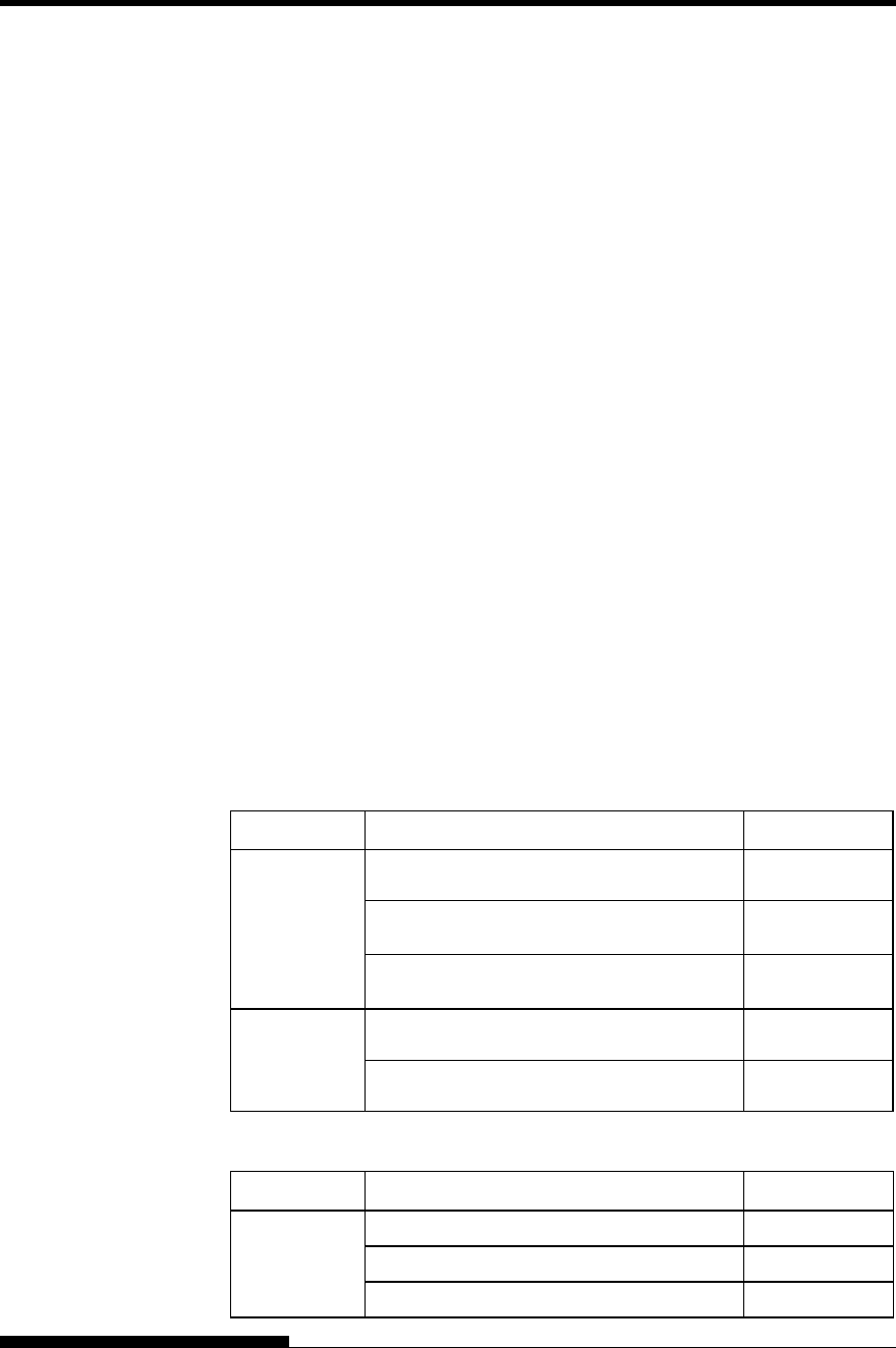
PRINTER AND PAPER SPECIFICATIONS
B-6 User's Manual
Print speed Print head wire
diameter 0.21mm
Print head wire
diameter 0.25mm
10 cpi 12 cpi 10 cpi 12 cpi
Letter: 180 cps 216 cps 150 cps 180 cps (MODE 1)
125 cps 150 cps 120 cps 144 cps (MODE 2)
Report: 360 cps 432 cps 300 cps 360 cps
Correspondence: 360 cps 432 cps 300 cps 360 cps
Draft: 720 cps 864 cps 600 cps 720 cps (MODE 1)
540 cps 648 cps 450 cps 540 cps (MODE 2)
Hi-speed draft: 720 cps 864 cps 600 cps 720 cps
Super-hi-speed draft: 800 cps 960cps 750 cps 900cps
cpi: characters per inch
cps: characters per second
Line feed speed 50 ms per line at 6 lines per inch
Form feed speed 9 inches per second
Ribbon life Up to 18 million characters
Certification
Safety:
Model Regulation Country
M33335A UL60950-1 United States
(for 100 V to 120 V) United States
CSA C22.2 No. 60950-1
(for 100 V to 120 V) Canada
CNS14336
(for 100 V to 120 V)
Taiwan
M33335B EN 60950-1
(for 220 V to 240 V)
Europe
BSMI(CNS14336)
(for 220 V to 240 V) Asia
EMI regulation:
Model Regulation Country
M33335A
CFR 47 FCC Part 15 Subpart B class B United States
ICES-003 class B Canada
CNS 13438 class B Taiwan
PERFORMANCE
SPECIFICATIONS

PRINTER AND PAPER SPECIFICATIONS
User's Manual B-7
M33335B
EN 55022 class B Europe
AS/NZS CISPR22 class B Australia and
New Zealand
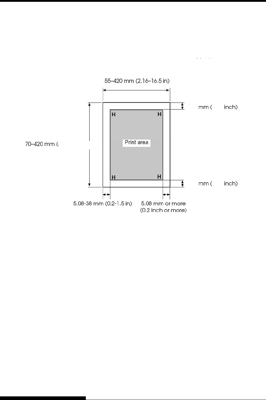
PRINTER AND PAPER SPECIFICATIONS
B-8 User's Manual
Print Area
This section illustrates the recommended print area for single sheets and
continuous forms.
Print area for single sheets
PAPER
SPECIFICATIONS
(2.75-16.5in)
4.23
0.16
0.16
4.23
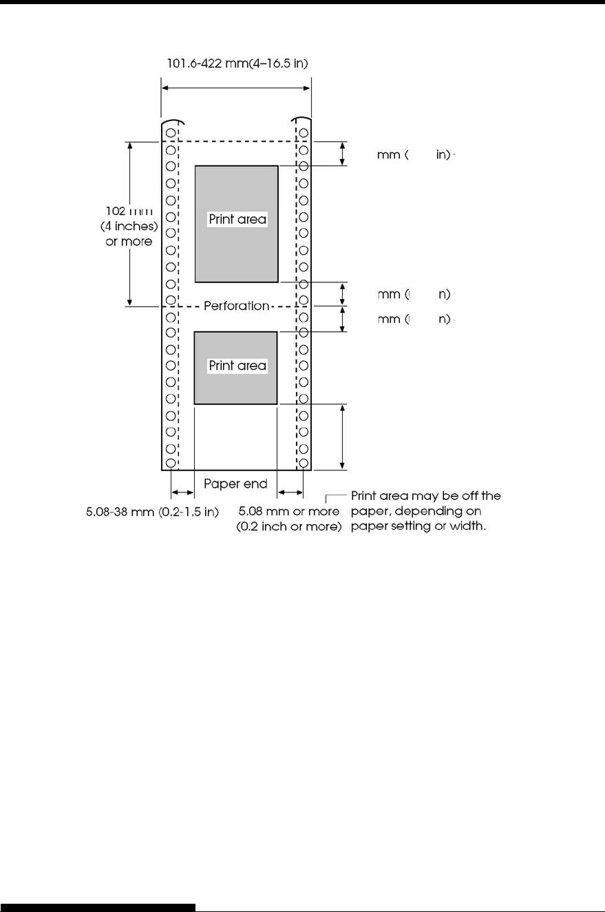
PRINTER AND PAPER SPECIFICATIONS
User's Manual B-9
Print area for continuous forms
Approx. 101 mm (4 inches)
for front tractor feed
Approx. 157 mm (6.2 inches)
for rear tractor feed
4.23
4.23
4.23
0.16
0.16
0.16
PRINTER AND PAPER SPECIFICATIONS
B-10 User's Manual
Paper Thickness
Paper thickness is given by the weight of the paper in either grams per
square meter (g/m2) or in pounds per bond (lbs/bond). The following
table shows the allowable paper thickness for one-part paper or for each
sheet of multipart paper. The total thickness must not exceed 0.65 mm
(0.026 inch).
The weight of carbonless or carbon-backed paper may vary, depending
upon the paper manufacturer. When using paper of borderline thickness,
test the paper before running a job.
Type of Paper Number of
Parts Thickness
One-part Single 47-81 g/m2 (40-70 kg or 12-22 lb)
Carbonless
Top
Bottom
40-64 g/m2 (34-55 kg or 11-17 lb)
40-81 g/m2 (34-70 kg or 11-22 lb)
Top
Middle
Bottom
40-50 g/m2 (34-43 kg or 11-13 lb)
40-50 g/m2 (34-43 kg or 11-13 lb)
40-81 g/m2 (34-70 kg or 11-22 lb)
Top
Middle (2-3p)
Bottom
40 g/m2 (34 kg or 11 lb)
40 g/m2 (34 kg or 11 lb)
40-81 g/m2 (34-70 kg or 11-22 lb)
Top
Middle (2-4p)
Bottom
40 g/m2 (34 kg or 11 lb)
40 g/m2 (34 kg or 11 lb)
40-64 g/m2 (34-55 kg or 11-17 lb)
Top
Middle (2-5p)
Bottom
40 g/m2 (34 kg or 11 lb)
40 g/m2 (34 kg or 11 lb)
40-64 g/m2 (34-55 kg or 11-17 lb)
kg: Weight in kilograms of 1000 sheets of 788 1091 mm paper
(1.16 g/m2)
lb: Weight in pounds of 500 sheets of 17 22 inch paper (3.76 g/m2)
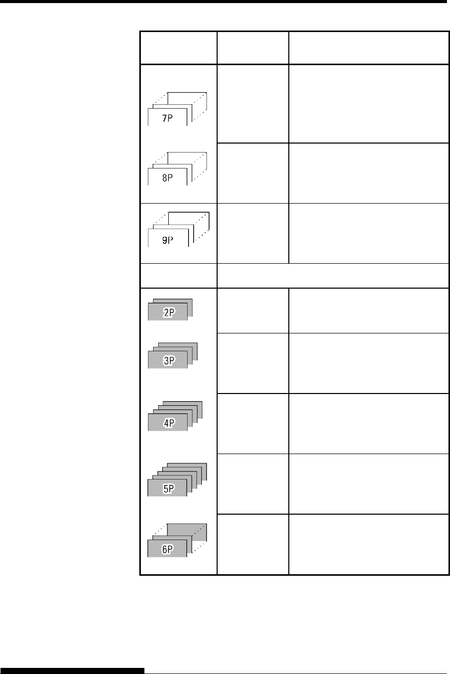
PRINTER AND PAPER SPECIFICATIONS
User's Manual B-11
Type of Paper Number of
Parts Thickness
Carbonless
Top
Middle (2-6p)
Bottom
40 g/m2 (34 kg or 11 lb)
40 g/m2 (34 kg or 11 lb)
40-64 g/m2 (34-55 kg or 11-17 lb)
Top
Middle (2-7p)
Bottom
40 g/m2 (34 kg or 11 lb)
40 g/m2 (34 kg or 11 lb)
40-64 g/m2 (34-55 kg or 11-17 lb)
Top
Middle (2-8p)
Bottom
40 g/m2 (34 kg or 11 lb)
40 g/m2 (34 kg or 11 lb)
40-64 g/m2 (34-55 kg or 11-17 lb)
Carbon-backed Do not use in high humidity environments.
Top
Bottom
40-64 g/m2 (34-55 kg or 11-17 lb)
40-81 g/m2 (34-70 kg or 11-22 lb)
Top
Middle
Bottom
40-52 g/m2 (34-45 kg or 11-14 lb)
40-52 g/m2 (34-45 kg or 11-14 lb)
40-81 g/m2 (34-70 kg or 11-22 lb)
Top
Middle (2-3p)
Bottom
40 g/m2 (34 kg or 11 lb)
40 g/m2 (34 kg or 11 lb)
40-81 g/m2 (34-70 kg or 11-22 lb)
Top
Middle (2-4p)
Bottom
40 g/m2 (34 kg or 11 lb)
40 g/m2 (34 kg or 11 lb)
40-64 g/m2 (34-55 kg or 11-17 lb)
Top
Middle (2-5p)
Bottom
40 g/m2 (34 kg or 11 lb)
40 g/m2 (34 kg or 11 lb)
40-64 g/m2 (34-55 kg or 11-17 lb)
kg: Weight in kilograms of 1000 sheets of 788 1091 mm paper
(1.16 g/m2)
lb: Weight in pounds of 500 sheets of 17 22 inch paper (3.76 g/m2)
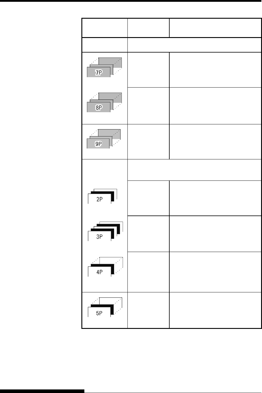
PRINTER AND PAPER SPECIFICATIONS
B-12 User's Manual
Type of Paper Number of
Parts Thickness
Carbon-backed Do not use in high humidity environments.
Top
Middle (2-6p)
Bottom
40 g/m
2
(34 kg or 11 lb)
40 g/m
2
(34 kg or 11 lb)
40-64 g/m
2
(34-55 kg or 11-17 lb)
Top
Middle (2-7p)
Bottom
40 g/m
2
(34 kg or 11 lb)
40 g/m
2
(34 kg or 11 lb)
40-64 g/m
2
(34-55 kg or 11-17 lb)
Top
Middle (2-8p)
Bottom
40 g/m
2
(34 kg or 11 lb)
40 g/m
2
(34 kg or 11 lb)
40-64 g/m
2
(34-55 kg or 11-17 lb)
Carbon-
interleaved
Avoid using carbon-interleaved single sheets.
Top
Carbon
Bottom
35-52 g/m
2
(30-45 kg or 9-14 lb)
Counted as one sheet
35-81 g/m
2
(30-70 kg or 9-22 lb)
Top
Carbon
Middle
Carbon
Bottom
35-46 g/m
2
(30-40 kg or 9-12 lb)
Counted as one sheet
35-46 g/m
2
(30-40 kg or 9-12 lb)
Counted as one sheet
35-64 g/m
2
(30-55 kg or 9-17 lb)
Top
Carbon
Middle (3,5P)
Carbon (4,6P)
Bottom
35-46 g/m
2
(30-40 kg or 9-12 lb)
Counted as one sheet
35-46 g/m
2
(30-40 kg or 9-12 lb)
Counted as one sheet
35-64 g/m
2
(30-55 kg or 9-17 lb)
Top
Carbon
Middle (3,5,7P)
Carbon (4,6,8P)
Bottom
35-46 g/m
2
(30-40 kg or 9-12 lb)
Counted as one sheet
35-46 g/m
2
(30-40 kg or 9-12 lb)
Counted as one sheet
35-64 g/m
2
(30-55 kg or 9-17 lb)
kg: Weight in kilograms of 1000 sheets of 788 1091 mm paper
(1.16 g/m
2
)
lb: Weight in pounds of 500 sheets of 17 22 inch paper (3.76 g/m
2
)

User's Manual C-1
C
APPENDIX C COMMAND SETS
COMMAND SETS
This appendix describes printer commands and
their parameters.
This printer has three resident command sets:
Fujitsu DPL24C PLUS (native command set for Fujitsu DL
series printers)
IBM Proprinter XL24E
Epson ESC/P2
Separate programmer s manuals are available for these emulations.
See Appendix A for order information.
Select the same emulation on the printer and in your software. If your
software emulations include DPL24C PLUS, select DPL24C PLUS for
optimum performance.
COMMAND SETS (DPL24CPLUS)
C-2 User's Manual
This section describes the printer commands for the DPL24C PLUS
command set which is the native command set of this printer. See the
Programmer’s Manual (DPL24C PLUS) for detailed information on
using these commands.
Function Command
Print Mode Control
Double-strike (bold) printing on
Double-strike (bold) printing off
Emphasized (shadow) printing on
Emphasized (shadow) printing off
Italic printing on
Italic printing off
Select character style and screening
n1= 0:Normal
1:Outline
2:Shaded
3:Outline and shaded
4:Thin outline
5:Thin shaded
6:Thin outline and shaded
n2= 0:Transparent
1:Light dot matrix
2:Heavy dot matrix
3:Vertical bars
4:Horizontal bars
5:Slants
6:Back slants
7:Lattice
One-line double width characters on
One-line double width characters off
Double width characters on/off
(on: n = 1, off: n = 0)
ESC G
ESC H
ESC E
ESC F
ESC 4
ESC 5
ESC e S (n1) (n2)
SO or ESC SO
DC 4
ESC W (n)
FUJITSU DPL24C
PLUS
COMMAND SETS
User's Manual C-3
Function Command
Double-height characters on/off
(on: n = 1, off: n = 0)
This command does not adjust the line
spacing.
Multiwidth and height printing
n = 0: Not adjusted
1: Character pitch multiplied
2: Line spacing multiplied
3: Character pitch and line spacing
multiplied
h1: Tens digit of horizontal multiple
h2: Units digit of horizontal multiple
v1: Tens digit of vertical multiple
v2: Units digit of vertical multiple
(0 < h1h2 or v1v2 < 11)
Condensed characters on
Condensed characters off
Subscript or superscript printing on
(subscript: n = 1, superscript: n = 0)
Subscript and superscript printing off
Select underline type
n = 0:Single line
1:Bold single line
2:Extremely bold single line
3:Double line
4:Bold double line
5:Extremely bold double line
Underline on/off
(on: n=1, off: n=0)
Overline on/off
(on: n=1, off: n=0)
ESC V (n)
ESC u (n) (h1) (h2)
(v1) (v2)
SI or ESC SI
DC2
ESC S (n)
ESC T
ESC e U (n)
ESC- (n)
ESC e o (n)
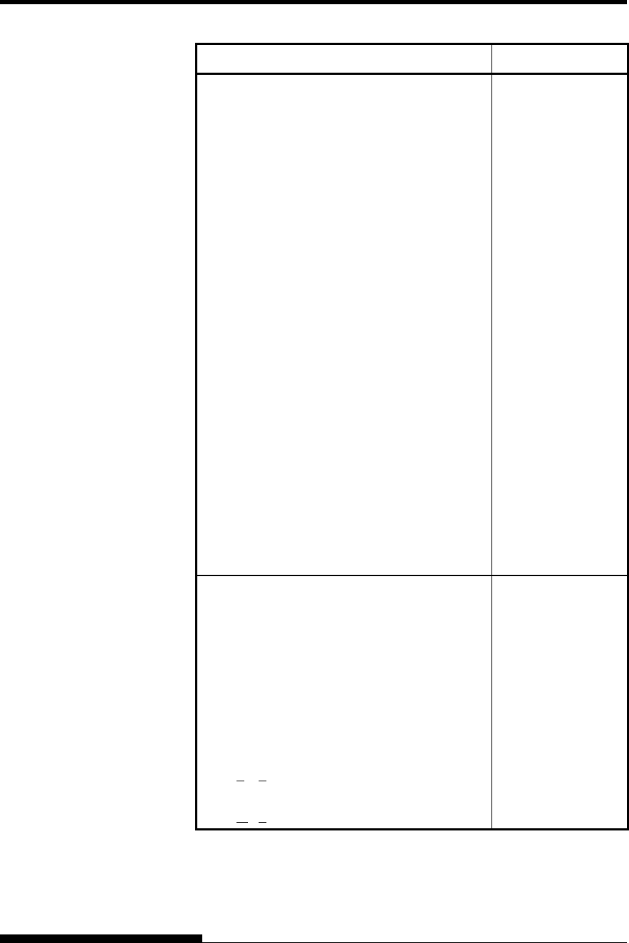
COMMAND SETS (DPL24CPLUS)
C-4 User's Manual
Function Command
Select printing style
This command allows you to combine
various printing styles. The value of n is
the sum of the values of the styles you
want to combine.
n= 0:Pica pitch
1:Elite pitch
4:Condensed
8:Shadow
16:Bold
32:Double width
64:Proportional
Select image overlay type
This command allows you to overlay a
pattern on characters.
n= 1:Light dot matrix
2:Heavy dot matrix
3:Vertical bars
4:Horizontal bars
5:Slants
6:Back slants
7:Lattice
Image overlay printing on/off
(on:n=1, off: n=0)
ESC ! (n)
ESC e I (n)
ESC e L (n)
Horizontal Control
Space
Backspace
Carriage return
Elite pitch (12 cpi)
Pica pitch (10 cpi)
Proportionally spaced characters on/off
(on:n=1, off: n=0)
Set character pitch to (n-1)/120 inch
(1 < n < 127)
Set character pitch to n/180 inch
(0 < n < 255)
SP
BS
CR
ESC M
ESC P
ESC p (n)
ESC US (n)
ESC h (n)

COMMAND SETS
User's Manual C-5
Function Command
Set character offset to n/120 inch
Cancelled by CR or ESC x.
(0 < n < 63) (64 < n < 127)
Set character pitch to n/360 inch
(0 < n1 n2 n3 < 999)
n1, n2, and n3 are the hundreds, tens, and
units digits.
ESC DC1 (n)
ESC e H
(n1) (n2) (n3)
Vertical Control
Line feed
Reverse line feed
Form feed
Advance paper n/180 inch (0 < n < 255)
Reverse paper n/180 inch (0 < n < 255)
Advance paper n/360 inch
(0 < n1 n2 n3 < 999)
n1, n2, and n3 are the hundreds, tens, and
units digits.
Reverse paper n/360 inch
(0 < n1 n2 n3 < 999)
n1, n2, and n3 are the hundreds, tens, and
units digits.
Set line spacing to 1/8 inch (8 lpi)
Set line spacing to n/180 inch
(0 < n < 255)
Set line spacing to 7/60 inch
Set line spacing to n/60 inch
(0 < n < 127)
Set line spacing to 1/6 inch (6 lpi) or to the value
set with the ESC A command.
The preset line spacing command is
ESC A (n).
Set line spacing to n/360 inch
(0 < n1 n2 n3 < 999)
n1, n2, and n3 are the hundreds, tens, and
units digits.
Set line spacing to n/360 inch
(1 < n < 255)
LF
LF ESC
FF
ESC J (n)
ESC j (n)
ESC e J
(n1) (n2) (n3)
ESC e j
(n1) (n2) (n3)
ESC 0
ESC 3 (n)
ESC 1
ESC A (n)
ESC 2
ESC e V
(n1) (n2) (n3)
FS 3 (n)

COMMAND SETS (DPL24CPLUS)
C-6 User's Manual
Function Command
Tabulation
Horizontal tab execution
Set horizontal tabs
The values of n1 to nk in this command
are the ASCII values of the print
columns (at the current character width)
at which tabs are to be set.
(1 < n < 255) (1 < k < 255)
Move to print column n (1 < n < 255)
Move dot column n/360 inch
(n = n1 + n2 256)
The value below is for 136-column printers.
(0 < n1 < 255) (0 < n2 < 19)
(0 < n2 256 + n1 < 4895)
Horizontal relative move by n/360 inch
(-999 < n1 n2 n3 < +999)
n1, n2, and n3 are the hundreds, tens, and
units digits of the distance.s is a plus
or minus ( + or -) sign.
Vertical tab execution
Set vertical tabs
The values of n1 to nk in this command
are the ASCII values of the lines (at the
current line spacing) at which tabs are
to be set.
(1 < n < 255) (1 < k < 64)
Move to line n (1 < n < 255)
HT
ESC D (n1) ... (nk)
NUL
ESC HT (n)
ESC $ (n1) (n2)
ESC e R (s)
(n1) (n2) (n3)
VT
ESC B (n1) ... (nk)
NUL
ESC VT (n)
Page Formatting
Set right margin (0 < n < 255)
Set left margin (0 < n< 255)
Set perforation skip by n lines
(1 < n < 127)
Perforation skip off
Set page length to n lines
(1 < n < 127)
ESC Q (n)
ESC 1 (n)
ESC N (n)
ESC O
ESC C (n) or
ESC FF (n)
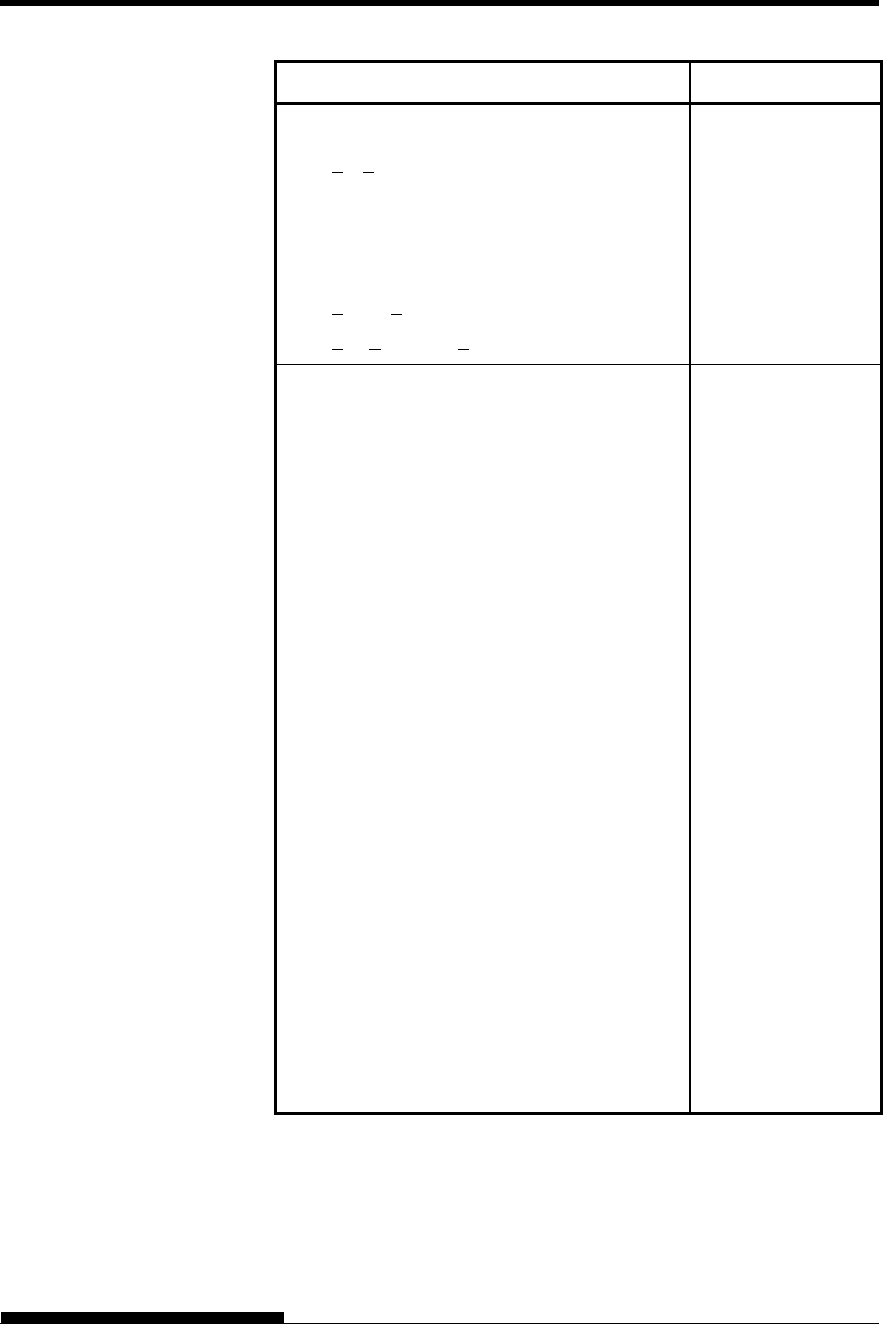
COMMAND SETS
User's Manual C-7
Function Command
Set page length to n inches
(1 < n < 22)
Set page length to n/360 inch
(n = n1 256 + n2)
(0 < n1 n2 < 255)
(1 < n1 < 256 + n2 < 7920)
ESC C NUL (n) or
ESC e C NUL (n) or
ESC FF NUL (n)
ESC e f (n1) (n2)
Character Set Control
Select character set 1
Appendix E gives the character sets
Select character set 2
Appendix E gives the character sets.
Select international character set
n = 0:USA
1:France
2:Germany
3:United Kingdom
4:Denmark 1/Norway
5:Sweden/Finland
6:Italy
7:Spain
8:Denmark 2
Clear print buffer
Select printer
Deselect printer (ignore input)
Force most significant bit to 1
Force most significant bit to 0
Cancel control over most significant bit
ESC 7
ESC 6
ESC R (n)
CAN
DC1
DC3
ESC >
ESC =
ESC #
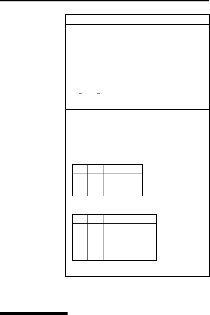
COMMAND SETS (DPL24CPLUS)
C-8 User's Manual
Function Command
Select code table
n = 0:Code page 437
1:Code page 850
2:Code page 860
3:Code page 863
4:Code page 865
5:ISO 8859-1/ECMA 94
Select extended character by character
number
(0 < n1 n2 n3 < 664)
n1, n2, and n3 are the hundreds, tens, and
units digits.
ESC e C (n)
ESC e E
(n1) (n2) (n3)
Word Processing
Line justification on
Automatically center printing
Reset word processing features
ESC m
ESC c
ESC x
Font Selection and Downloading
Select font m with source and style set by n
m (bits 0 and 1: Font device selection)
Bit 1 Bit 0 Selection of font
0
0
1
0
1
0
Resident font
Downloaded font
Resident font
m (bits 2 and 3: Print quality specification
Bit 3 Bit 2 Print quality
0
0
1
1
0
1
0
1
Original quality of font
Letter quality (360 dpi)
Correspondence
quality (180 dpi)
Draft quality (120 dpi)
ESC % (m) (n)
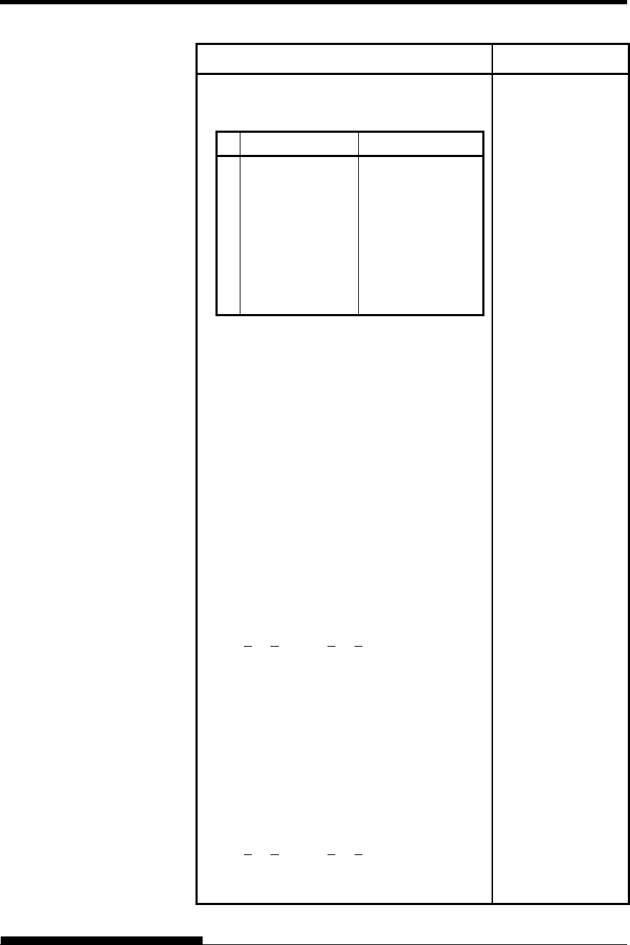
COMMAND SETS
User's Manual C-9
Function Command
n (bit 0 to 2: Specification of font number)
(1) Resident fonts
n m (bit 1, 0) = 0, 0 m (bit 1, 0) = 1, 0
0
1
2
3
4
5
6
7
Courier 10
Prestige elite 12
Draft
Compressed
Boldface PS
Pica 10
Correspondence
High-speed draft
OCR-B
OCR-A
(2) Downloaded fonts
n = 0: Downloaded font 0
1: Downloaded font 1
Select print quality (font attributes)
n = 0:Letter (360 180 dpi)
1:Correspondence (180 180 dpi)
2:Draft (120 180 dpi)
3:High-speed Draft (90 180 dpi)
4:Super-High-speed Draft (72180 dpi)
Select spacing mode (font attributes)
n = 0:Fixed pitch font
1:Proportional spacing font
Select character pitch (n/360 inch, font
attributes)
(0 < n1 < 255) (1 < n2 < 255)
(n = n1 256 + n2)
Ex.n = 36: 10 pitch
30: 12 pitch
24: 15 pitch
21: 17 pitch
Condense/enlarge vertically (font attributes)
n = 1:Executed
0:Not executed
Select point size (n/1200 inch, font attributes)
(0 < n1 < 255) (0 < n2 < 255)
(n = n1 256 + n2)
Ex. n =166: 10 point
ESC e q (n)
ESC e s (n)
ESC e p (n1) (n2)
ESC e A (n)
ESC e v (n1) (n2)
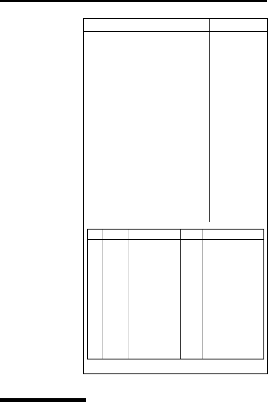
COMMAND SETS (DPL24CPLUS)
C-10 User's Manual
Function Command
Select character style (font attributes)
n = 0:Upright
1:Italic
Select stroke weight (font attributes)
n = 249:-7 (reserved)
251:-5 (reserved)
253:-3 (light)
0:0 (medium)
3:3 (bold)
5:5 (black)
7:7 (ultrablack)
Select typeface (font attributes)
n = 1:Pica
3:Courier (bitmap)
4:Nimbus Sans
5:Timeless
6:Gothic
8:Prestige
23:Boldface
130:OCR-A
131:OCR-B
134:Courier (scalable)
Select font by I.D. (font attributes)
ESC e i (n)
ESC e w (n)
ESC e t (n)
ESC e F (n)
n Quality Spacing Pitch Point Typeface
1
2
3
4
9
10
32
34
128
129
130
132
133
134
140
141
142
LQ
LQ
LQ
LQ
LQ
LQ
LQ
LQ
LQ
LQ
LQ
LQ
LQ
LQ
LQ
LQ
LQ
Fixe
d
Fixed
PS
Fixed
Fixed
Fixed
Fixed
Fixed
PS
PS
PS
PS
PS
PS
Fixed
Fixed
Fixed
10 cpi
12 cpi
-
10 cpi
10 cpi
10 cpi
10 cpi
12 cpi
-
-
-
-
-
-
10 cpi
10 cpi
10 cpi
12 pt
10 pt
12 pt
12 pt
12 pt
12 pt
12 pt
11pt
10 pt
10 pt
10 pt
10 pt
10 pt
10 pt
10 pt
10 pt
Courier (bitmap)
Prestige
Boldface
Pica
OCR-A
OCR-B
Courier (bitmap)
Gothic
Timeless
Timeless Italic
Timeless Bold
Nimbus Sans
Nimbus Sans Italic
Nimbus Sans Bold
Courier (scalable)
Courier Bold (scalable)
Courier Italic (scalable)
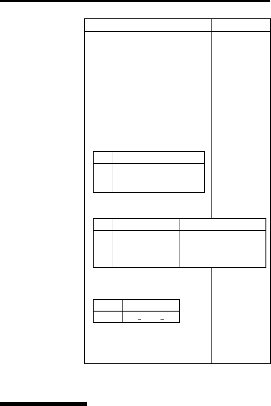
COMMAND SETS
User's Manual C-11
Function Command
Copy resident font to download area
m = 0:Courier 10
1:Prestige Elite 12
2:Draft
3:Compressed
4:Boldface PS
5:Pica 10
6:Correspondence
7:High-speed Draft
n = 0:Downloaded font 0
1:Downloaded font 1
Create download font
m (bits 4 and 5: Specifies the quality of
characters to be registered)
Bit 5 Bit 4 Font quality selection
0
1
1
1
0
1
Letter (360 dpi)
Correspondence (180 dpi)
Draft (120 dpi)
m (bit 0: Specifies external font number
to be registered)
ESC : NUL (m) (n)
ESC & (m) (Cs)
(Ce) (data)
Bit 0 Font number selection Remarks
0 Downloaded font 0 At power on, resident font 0 is
automatically downloaded.
1 Downloaded font 1 At power on, resident font 1 is
automatically downloaded.
m (bits 1, 2, 3, 6, 7) Not used (don’t care)
Cs (Download start character, ASCII code)
Ce (Download end character, ASCII code)
Decimal 00 < Cs, Ce < 255
Hex 00 < Cs, Ce < FF
Precaution: Ce Cs
data (More than one byte of data
containing bit map data)
(Reserved)
ESC e D (data);
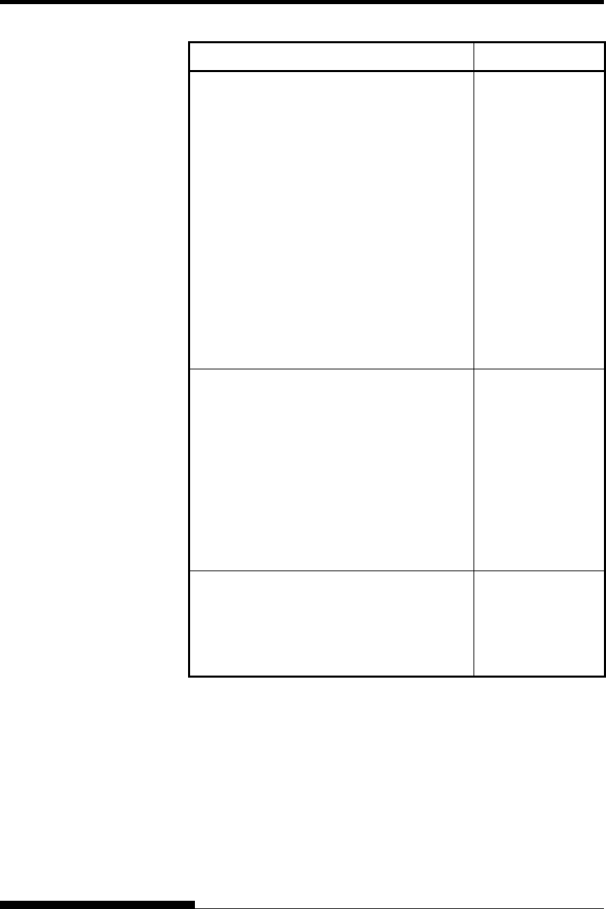
COMMAND SETS (DPL24CPLUS)
C-12 User's Manual
Function Command
Bit Image Graphics
Graphics type m graphics
Graphics type m graphics
Single-density graphics
Double-density graphics
High-speed double-density graphics
Quadruple-density graphics
360 dot per inch 24-pin graphics
ESC * (m)
(n1) (n2) (data)
ESC e b (m)
(n1) (n2) (data) or
ESC e B (m)
(n1) (n2) (data)
ESC K (n1) (n2) (data)
ESC L (n1) (n2) (data)
ESC Y (n1) (n2) (data)
ESC Z (n1) (n2) (data)
FS Z (n1) (n2) (data)
Cut Sheet Feeder Control
Feed a sheet from bin 1
Feed a sheet from bin 2
Feed a sheet from bin 3
Eject a page from the printer
Select bin 1 for following pages
Select bin 2 for following pages
Select bin 3 for following pages
ESC EM 1
ESC EM 2
ESC EM E
ESC EM R
/ / 1 / /
/ / 2 / /
/ / E / /
Initialize Printer
Reset printer
Reset printer
Initialize printer
ESC @
ESC CR P
ESC SUB I
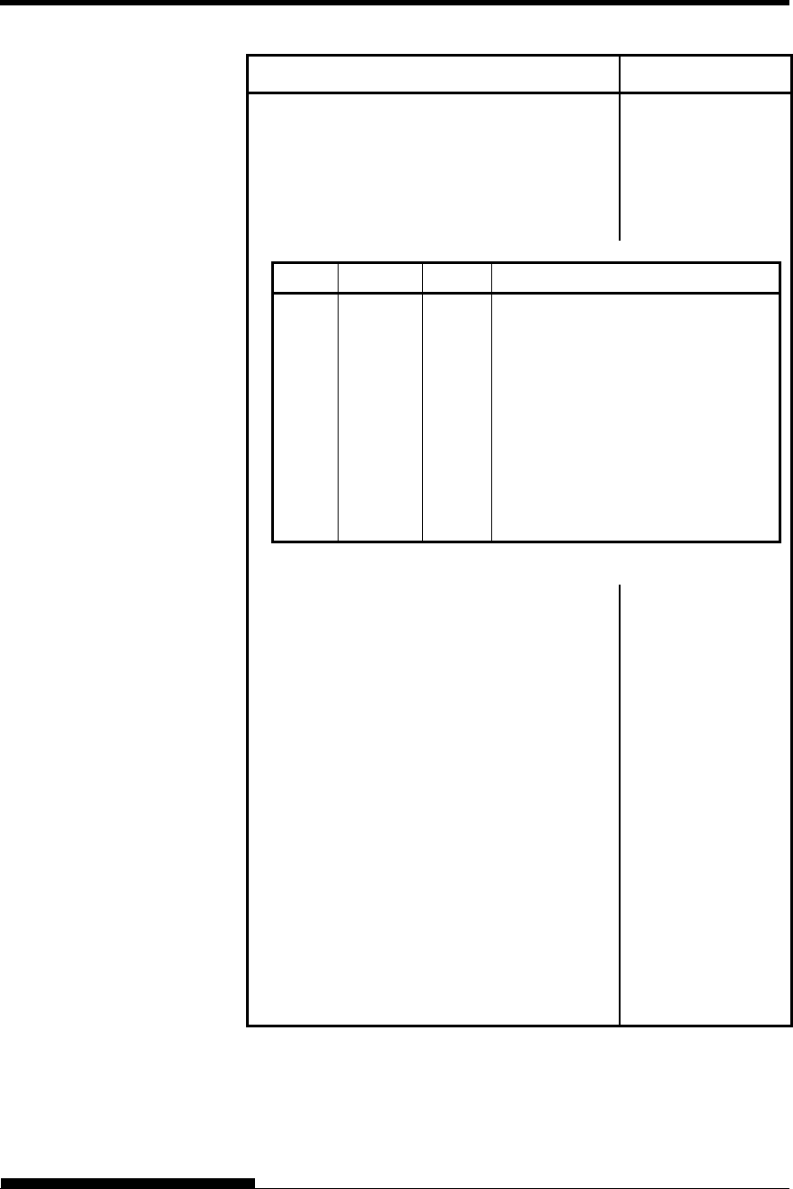
COMMAND SETS
User's Manual C-13
Function Command
Bar Code Printing
Print bar code
b: Total number of parameters
R: (fixed)
c: Type of bar code
ESC DC4 (b) R
(c) (w) (h) (a)
(ch1) ... (chn)
ASCII Decimal Hex Type
1
2
3
4
5
6
7
A
B
a
49
50
51
52
53
54
55
65
66
97
31
32
33
34
35
36
37
41
42
61
Codabar (nw-7)
EAN 13
EAN 8
Code 3 of 9
Industrial 2 of 5
Interleaved 2 of 5
Matrix 2 of 5
UPC type A
Code 128
UPC type A with checkdigit printing
w: Width of narrow bar in 1/1440-inch
units
h: Height of bar code
a: Defines check characters and OCR
characters
ch1 ... chn: Bar code characters
NOTE
When EAN13, UPC type A, or UPC type A
with checkdigit printing is selected as the type
of barcode, printing the barcode from the left
(from the first dot) will cause the omission of
a flag character that should by printed on the
lower left or middle left of it. Therefore,
when printing these types of barcode, leave
two or more spaces open from the left.
See the next page for details of the Bar Code
Command.
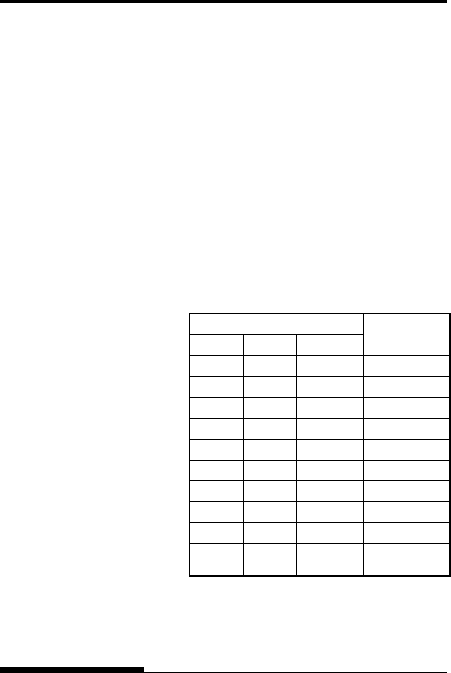
COMMAND SETS (DPL24CPLUS)
C-14 User's Manual
Bar Code Printing Control
ASCII : ESC + DC4 + b + R + c + w + a + ch1 … + chn
Hexadecimal : 1B + 14 + b + 52 + c + w + a + ch1 … + chn
Decimal : 27 + 20 + b + 82 + c + w + a + ch1 … + chn
(1) Function
(a) Instructs the printing of bar codes according to the different
specifications of this command.
(2) Valid range of parameters
(a) b (Specification of number of bytes) = Actual number of data +
6
(b) R (Fixed)
ASCII : R
Hexadecimal : 82
Decimal : 52
(c) C (Specifies the type of bar code to be printed. No printing is
done if any value other than the following is specified.)
C Type of bar code
ASCII Decimal Hexadecimal
1 49 31 Codabar (nw-7)
2 50 32 EAN 13
3 51 33 EAN 8
4 52 34 Code 3 of 9
5 53 35 Industrial 2 of 5
6 54 36 Interleaved 2 of 5
7 55 37 Matrix 2 of 5
A 65 41 UPC type A
B 66 42 CODE 128
a 97 61
UPC type A with
check character
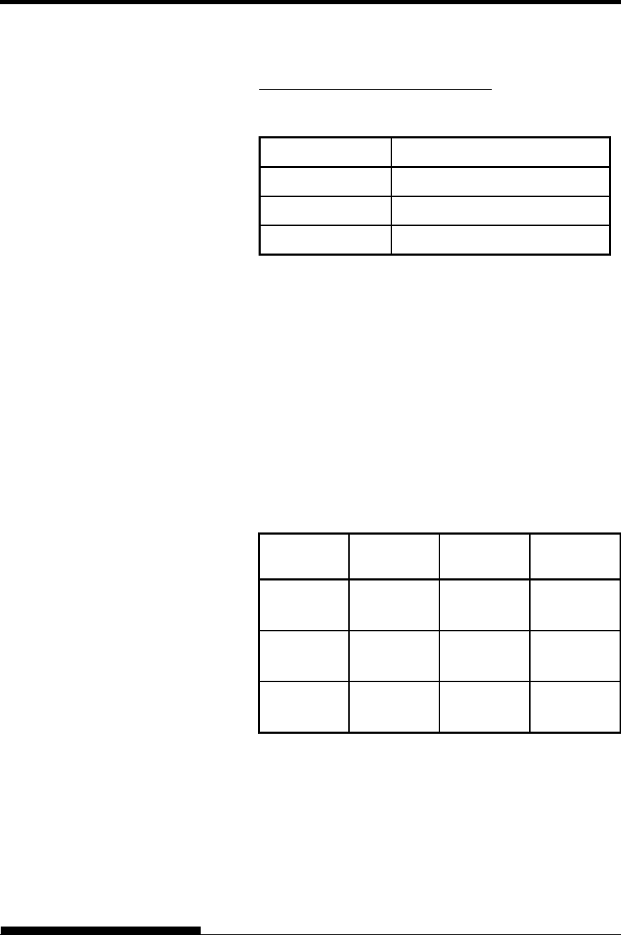
COMMAND SETS
User's Manual C-15
(d) w (Specify the width of the narrow bar of the bar code to be
printed in units of 1/1440.)
Specify the “Logical value” to be printed (in units of 1/1440).
Actual printing: The printer prints with the width given in the
following table in units of 1/180 inches.
w Width of narrow bar
1 ~ 19 2 Dots (2/180 inches)
20 ~ 27 3 Dots (3/180 inches)
28 ~ 4 Dots (4/180 inches)
(e) h (Specify the height of the bar code to be printed in units of
1/1440 taking the narrow bar width as the reference.)
Height of bar code = (parameter w) (parameter h) [in units
of 1/1440]
Height of bar code 11 Inches
Actual printing: The printing is done with the following initial
values if the bar code height is less than or
equal to 24 dots taking 1 dot equal to 1/180
inches of the printing unit of the printer.
The following values are the standard heights for the respective
bar code standards. Enter the value so that the height is ≤
23/180 if the standard is correct.
Narrow bar
width EAN
13/UCP-A EAN 8 Others
2 Dots
(16/1440)
162 Dots
(1296/1440)
130 Dots
(1040/1040)
108 Dots
(864/1440)
3 Dots
(24/1440)
234 Dots
(1872/1440)
187 Dots
(1496/1040)
135 Dots
(1080/1440)
4 Dots
(32/1440)
312 Dots
(2496/1440)
249 Dots
(1992/1040)
162 Dots
(1296/1440)
Figures in parentheses ( ) are values converted to units of
1/1440.
..
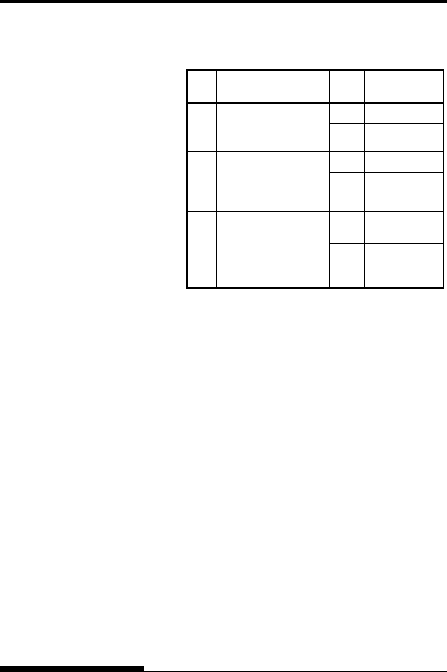
COMMAND SETS (DPL24CPLUS)
C-16 User's Manual
(f) a (Bits 2~0: Specifications related to the check and OCR
characters.)
Bit Content of specification value Content of
setting
0
Check character
Additional specification
* 1
0 Added
1 Not added
1
Specification of OCR
character printing
(OCR-B is taken as the
standard)
0 Printed
1 Not printed
2
Printing position of
EAN, UPC flag
character
0 To the left of the
bar code
1
To the bottom
left of the bar
code
*1: The specification becomes invalid for the following bar
codes:
Codabar … Always the non-additional code is set.
EAN, UPC … Always the additional code is set.
*2: The flag character is printed when Bit 1 = 0.
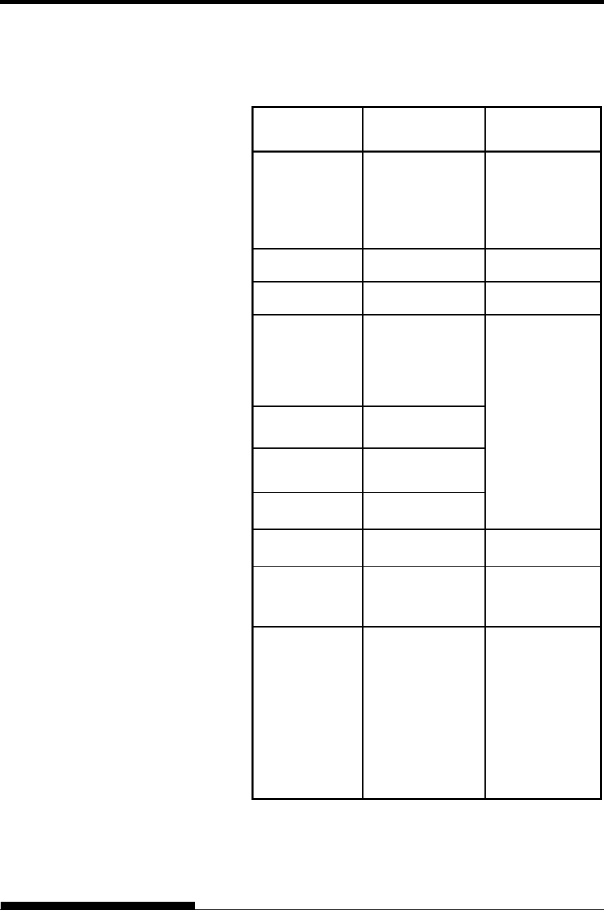
COMMAND SETS
User's Manual C-17
(g) (ch1) … (chn)
The data and the printable character set are listed below.
Type of bar
code Usable character
set Data count
Codabar Numerals: 0 ~ 9
Symbols; + -, $/:
Start, Stop:
A,a,B,b,C,c,D,d,
T,t,N,n,*,E,e
1 ≤ n ≤ 64
Includes Start and
Stop
EAN 13 Numerals: 0 ~ 9 Fixed at n=12
EAN 8 Numerals: 0 ~ 9 Fixed at n=7
Code 3 of 9 Numerals: 0 ~ 9
Alphabets: A ~ Z:
Symbols:
+-,$/%SPACE
Start, Stop:*
Check character
Additional code
1 ≤ n ≤ 63
Check character
Non-additional
code
1 ≤ n ≤ 64
Industrial 2 of 5 Numerals: 0 ~ 9
Interleaved
2 of 5 Numerals: 0 ~ 9
Matrix 2 of 5 Numerals: 0 ~ 9
UPC Type A Numerals: 0 ~ 9 Fixed at n=11
UPC Type A
with check
character
Numerals: 0 ~ 9 Fixed at n=11
Code 128
ASCII Code
Start code: A, B, C
Code set C: 0 ~ 9
Check character
Additional code
1 ≤ n ≤ 63
Check character
Non-additional
code
1 ≤ n ≤ 64
Code set C: 2n
COMMAND SETS (DPL24CPLUS)
C-18 User's Manual
Function Command
Print Option Control
Friction feed selection
Rear tractor feed selection
Front tractor feed selection
Cut sheet feed selection
Host controlled paper path control
n = “F” :Friction
“T” :Rear Tractor
“M” : Front Tractor
Automatic paper thickness control
/ / F / /
/ / T / /
/ / M / /
/ / S / /
ESC e T (n)
ESC e P (n1) (n2) (n3) (n4)
Miscellaneous
Sound bell
Enable paper-out sensor
Ignore paper-out sensor
Typewriter mode on/off
(on:n=1, off: n=0)
Move print head to home position
Unidirectional printing on/off
(on:n=1, off: n=0)
Select CR code definition
n = 0:CR = CR only
1:CR = CR + LF
Select LF code definition
n = 0:LF = LF only
1:LF = LF + CR
Enter online setup mode
Move print head (unit: 1/180 inch)
(0 < n1 < 255) (0 < n2 < 255)
BEL
ESC 9
ESC 8
ESC i (n)
ESC <
ESC U (n)
ESC e r (n)
ESC e l (n)
ESC e ONLINE (data)
ESC e h (n1) (n2)
COMMAND SETS
User's Manual C-19
Factory Default Settings
The following table describes the printer commands used to control
options of the items that can be selected in printer setup mode. Command
parameters are omitted
Item Selectable options in setup mode Command
Emulate DPL24C+, XL24E, ESC/P2 Controllable in
online setup mode
Font COUR 10, PRSTG 12, COMPRSD,
BOLDFCE, PICA 10, CORRESP,
COUR-N, COUR-B, COUR-I,
TIMLS-N, TIMLS-B, TIMLS-I,
N.SAN-N, N.SAN-B, N.SAN-I.
OCR-B, OCR-A, DOWNLD 0,
DOWNLD 1
ESC e t
ESC e F
ESC %
Quality LETTER, REPORT, DRAFT, HI-
DRFT, SH-DRFT
ESC e q
Pitch 2.5, 3, 5, 6, 10, 12, 15, 17, 18, 20 CPI
or PROP SP
ESC e p
ESC e H
ESC h
ESC US
ESC M
ESC P
ESC p
ESC i
ESC e s
Line
space
1, 2, 3, 4, 5, 6, 7, 8, LPI ESC e V
ESC 0
ESC 1
ESC 2
ESC 3
ESC A
Character
width
NORMAL, 2 TIMES, 4 TIMES ESC W
SO or ESC SO
(DC4) ESC u
ESC !
Character
height
NORMAL, 2 TIMES, 4 TIMES ESC V
ESC u
Underline: Factory default
( ): Cancel command
COMMAND SETS (DPL24CPLUS)
C-20 User's Manual
Item Selectable options in setup mode Command
Attributes NONE, ITALICS, CONDNSD,
SHADOW, BOLD
ESC 4 (ESC 5)
SI or ESC SI
(DC2)
ESC E (ESC F)
ESC G (ESC H)
ESC e i ESC !
Page
length
3.0, 3.5, 4.0, 5.0, 5.5, 6.0, 7.0, 8.0,
8.5, 11.0, 11.6, 12.0, 14.0, 18.0 IN
ESC C NUL
ESC e C NUL
ESC FF NUL
ESC C
ESC e C
ESC FF
Left end 1 , 2, 3, ... , 41 COLM Controllable in
online setup mode
Top
margin
1 , 2, 3, ... , 10 LINE Controllable in
online setup mode
Language USA, UK, GERMAN, FRENCH,
ITALIAN, SPANISH, SWEDISH,
FINNISH, DANISH1, DANISH2,
NORWEGN, PAGE437, PAGE850,
PAGE860, PAGE863, PAGE865
ISO8859, ECMA94
ESC R
ESC e C
PG852, PG852-T, PG855, PG866,
HUNGARY, HUNG-T, SOLV,
SOLV-T, POLISH, POLSH-T,
MAZOWIA, MAZOW-T, LATIN7,
LATIN2, LATN2-T, KAMENIC,
KAMEN-T, TURKY, TURKY-T,
CYRILIC, IBM437, IBM851,
ELOT928, PG-DHN, LATIN-P,
ISO-LTN, LITHUA1, LITHUA2,
MIK, MACEDON, ABG, ABY, PG-
MAC, ELOT927, DEC-GR, GREEK
11, PG862, HBR-OLD, HBR-DEC,
ISO-TUK, RUSCII, LATIN-9 ,
WCP1250, WCP1251, WCP1252
Uncontrollable by
commands but
controllable in
online setup mode
Underline: Factory default
( ): Cancel command
COMMAND SETS
User's Manual C-21
Item Selectable options in setup mode Command
Character
set
SET 1, SET2 ESC7 ESC6
Perfora-
tion skip
SKIP, NO-SKIP ESC N (ESC O)
Paper
width
8.0 IN, 11.0 IN, 11.4 IN, 13.6IN, (8.0
IN is default for 80-column printer,
and 13.6 IN is default for 136-
column printer)
Controllable in
online setup mode
Zero font NO-SLSH, SLASH Controllable in
online setup mode
DC3 ENABLE, DISABLE Controllable in
online setup mode
CR code CR-ONLY, CR & LF ESC e r
LF code LF-ONLY, LF & CR ESC e l
Right end
wrap
WRAP, OVR-PRT Controllable in
online setup mode
Paper-out CNTONLY, DETECT, IGNORE ESC 9 (ESC 8)
Print
direction
BI-DIR, UNI-DIR ESC U
Print
mode
NORMAL, HISPEED, QUIET ESC e X
ESC e O
High
Impact
DISABLE, ENABLE ESC e z
Underline: Factory default
( ): Cancel command
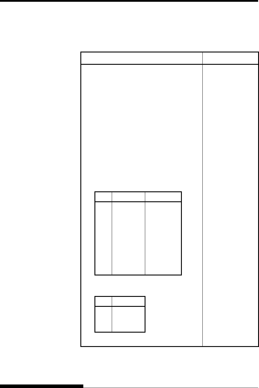
COMMAND SETS (IBM XL24E)
C-22 User's Manual
This section describes the printer commands for the IBM Proprinter
XL24E emulation. Asterisks in the “Function” column indicate extended
commands that are not supported by the original printer.
Function Command
Print Mode Control
Double-strike (bold) printing on
Double-strike (bold) printing off
Emphasized (shadow) printing on
Emphasized (shadow) printing off
One-line double-width characters on
One-line double-width characters off
Double-width characters on/off
(on: n = 1, off: n = 0)
Double-height/double-width characters
n1 = 4, n2 = 0, m1 = 0, m2 = 0
m3 controls character height and line spacing:
m3 Height Spacing
0
1
2
16
17
18
32
33
34
Unchanged
Normal
Double
Unchanged
Normal
Double
Unchanged
Normal
Double
Unchanged
Unchanged
Unchanged
Single
Single
Single
Double
Double
Double
m4 controls character width:
m3 Height
0
1
2
Unchanged
Normal
Double
ESC G
ESC H
ESC E
ESC F
SO or ESC SO
DC4
ESC W (n)
ESC [ @ (n1)(n2)
(m1) ... (m4)
IBM PROPRINTER
XL24E EMULATION
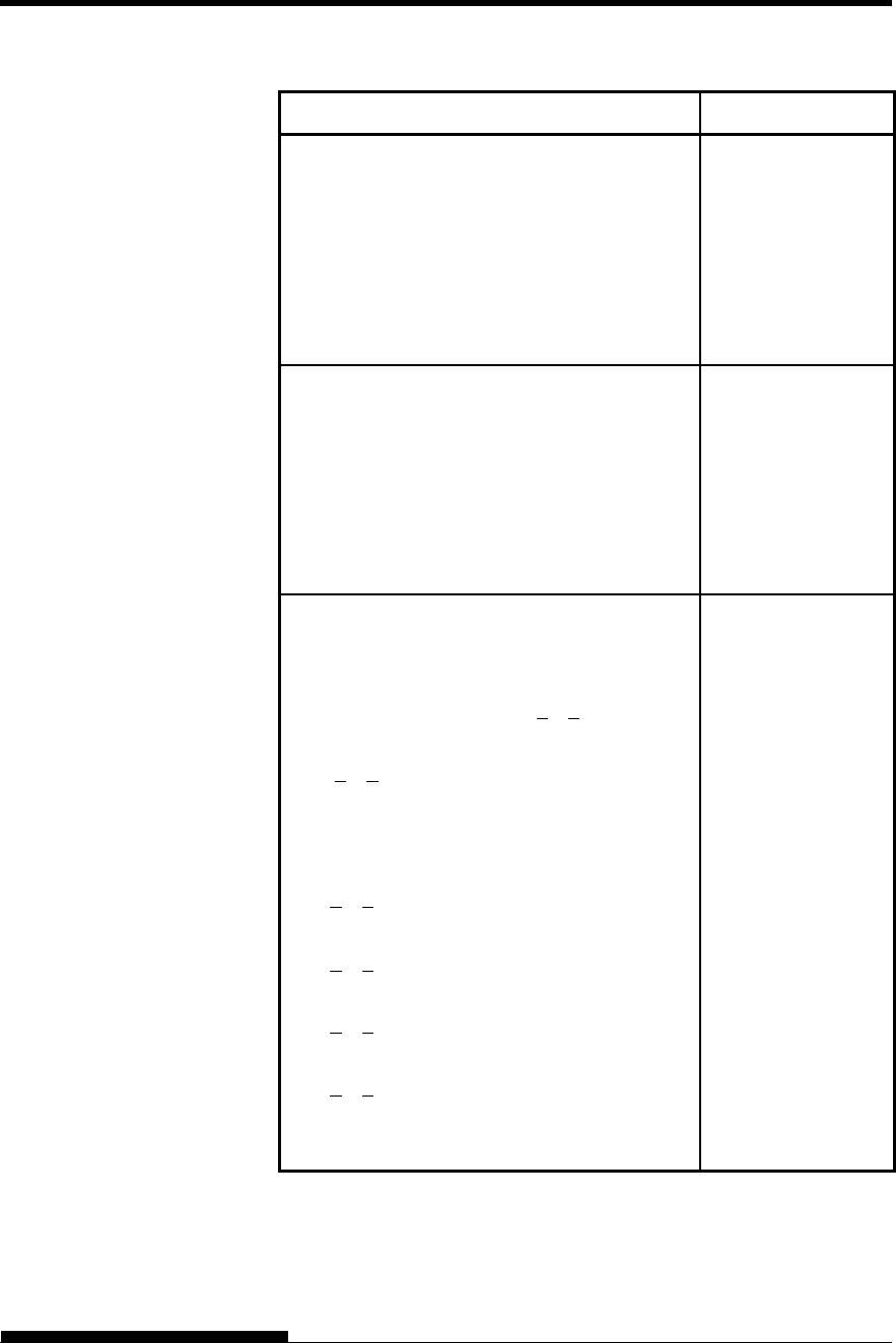
COMMAND SETS
User's Manual C-23
Function Command
Condensed characters on
Condensed and elite characters off
Subscript or superscript printing on
(subscript: n = 1, superscript: n = 0)
Subscript and superscript printing off
Underline on/off (on: n = 1, off: n = 0)
Overline on/off (on: n = 1, off: n = 0)
SI or ESC SI
DC2
ESC S (n)
ESC T
ESC - (n)
ESC_(n)
Horizontal Control
Space
Backspace
Carriage return
Elite characters on
Proportionally spaced characters on/off
(on:n= 1, off: n= 0)
SP
BS
CR
ESC:
ESC P (n)
Vertical Control
Line feed
Form feed
Advance paper n/216 inch (1 < n < 255)
Advance paper n/180 inch (in AG mode)
(1 < n < 255)
Set line spacing to 1/8 lines
Set line spacing to 7/72 inch
Set line spacing to n/216 inch
(0 < n < 255)
Set line spacing to n/180 inch (in AG mode)
(0 < n < 255)
Preset line spacing to n/72 inch
(1 < n < 255)
Preset line spacing to n/60 inch (in AG mode)
(1 < n < 255)
Set line spacing to 1/6 inch or to the value
preset by line spacing command ESC A (n)
LF
FF
ESC J (n)
ESC J (n)
ESC 0
ESC 1
ESC 3 (n)
ESC 3 (n)
ESC A (n)
ESC A (n)
ESC 2
COMMAND SETS (IBM XL24E)
C-24 User's Manual
Function Command
Change graphics line spacing base to
1/216 or 1/180 inch (for ESC J and ESC 3)
m1 = 4, m2 = 0
0 < t1 < 255, 0 < t2 < 255, t3 = 0
t4 = 180 or 216
ESC [ \ (m1) (m2)
(t1) ... (t4)
Tabulation
Horizontal tab execution
Set horizontal tabs
The values of n1 to nk in this command
are the ASCII values of the print columns
(at the current character width) at which
tabs are to be set. (1 < n< 255) (1 < k < 28)
Clear all horizontal tabs
Move print position right by n/120 inch
(0 < n1, n2 < 255) (n = n1 + n2 256)
Vertical tab execution
Set vertical tabs
The values of n1 to nk in this command
are the ASCII values of the lines (at the
current line spacing) at which tabs are to be
set. (1 < n < 255) (1 < k < 64)
Clear all vertical tabs
Reset tabs to default values
HT
ESC D (n1)...
(nk) NUL
ESC D NUL
ESC d (n1)(n2)
VT
ESC B (n1)...
(nk) NUL
ESC B NUL
ESC R
Page Formatting
Set left margin at column n and right
margin at column m (0 < n, m < 255)
Set perforation skip by n lines
(1 < n < 255)
Perforation skip off
Set page length to n lines (1 < n < 255)
Set page length to n inches (1 < n < 22)
Set top of form
ESC X (n) (m)
ESC N (n)
ESC O
ESC C (n)
ESC C NUL (n)
ESC 4
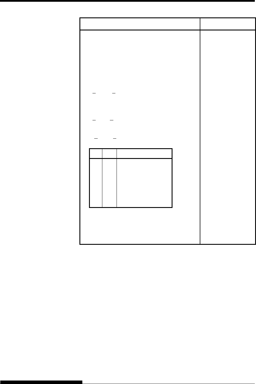
COMMAND SETS
User's Manual C-25
Function Command
Character Set Control
Select character set 1
Select character set 2
Print n1+ n2 256 characters from all-
character set
(chars.: codes of characters to print,
0 < chars. < 255)
Print a character from all-character set
(char.: a code of character to print,
0 < char. < 255)
Select code page table n
(0 < n1, n2 < 255) (n = n1+ n2 256)
c1c2Code page ID
0
1
3
3
3
3
0
181
82
92
95
97
Ignore command
Code page 437
Code page 850
Code page 860
Code page 863
Code page 865
Clear input buffer
Select printer
Deselect printer (ignore input)
ESC 7
ESC 6
ESC \ (n1)(n2)
(chars.)
ESC ^ (char.)
ESC [ T (n1)(n2)
0 0 (c1)(c2)
CAN
DC1
ESC Q #

COMMAND SETS (IBM XL24E)
C-26 User's Manual
Function Command
Downloading
Select resident or downloaded font
Ex.n = 0:Resident Draft
2:Resident Courier
4:Downloaded Draft
6:Downloaded Courier
Create download font
ESC I (n)
ESC = (n1) (n2)
ID (m1) (m2) (data)
Bit Image Graphics
Single-density graphics
Double-density graphics
High-speed double-density graphics
Quadruple-density graphics
High-resolution graphics
Select graphics mode (in AG mode only)
ESC K (n1)(n2) (data)
ESC L (n1)(n2) (data)
ESC Y (n1)(n2) (data)
ESC Z (n1)(n2) (data)
ESC [ g (n1)(n2)
(m) (data)
ESC * (m) (c1) (c2)
(data)
Cut Sheet Feeder Control
Feed a sheet from bin 1
Feed a sheet from bin 2
Feed a sheet from bin 3
Eject a page from the printer
Select bin 1 for following pages
Select bin 2 for following pages
Select bin 3 for following pages
Change bins at next page
ESC EM 1
ESC EM 2
ESC EM E
ESC EM R
/ / 1 / /
/ / 2 / /
/ / E / /
/ / C / /
Print Option Control
Friction feed selection
Rear tractor feed selection
Front tractor feed selection
Cut sheet feed selection
Host controlled paper path control
n = “F” :Friction
“T” :Rear Tractor
“M” : Front Tractor
Automatic paper thickness control
/ / F / /
/ / T / /
/ / M / /
/ / S / /
ESC e T (n)
ESC e P (n1) (n2) (n3) (n4)
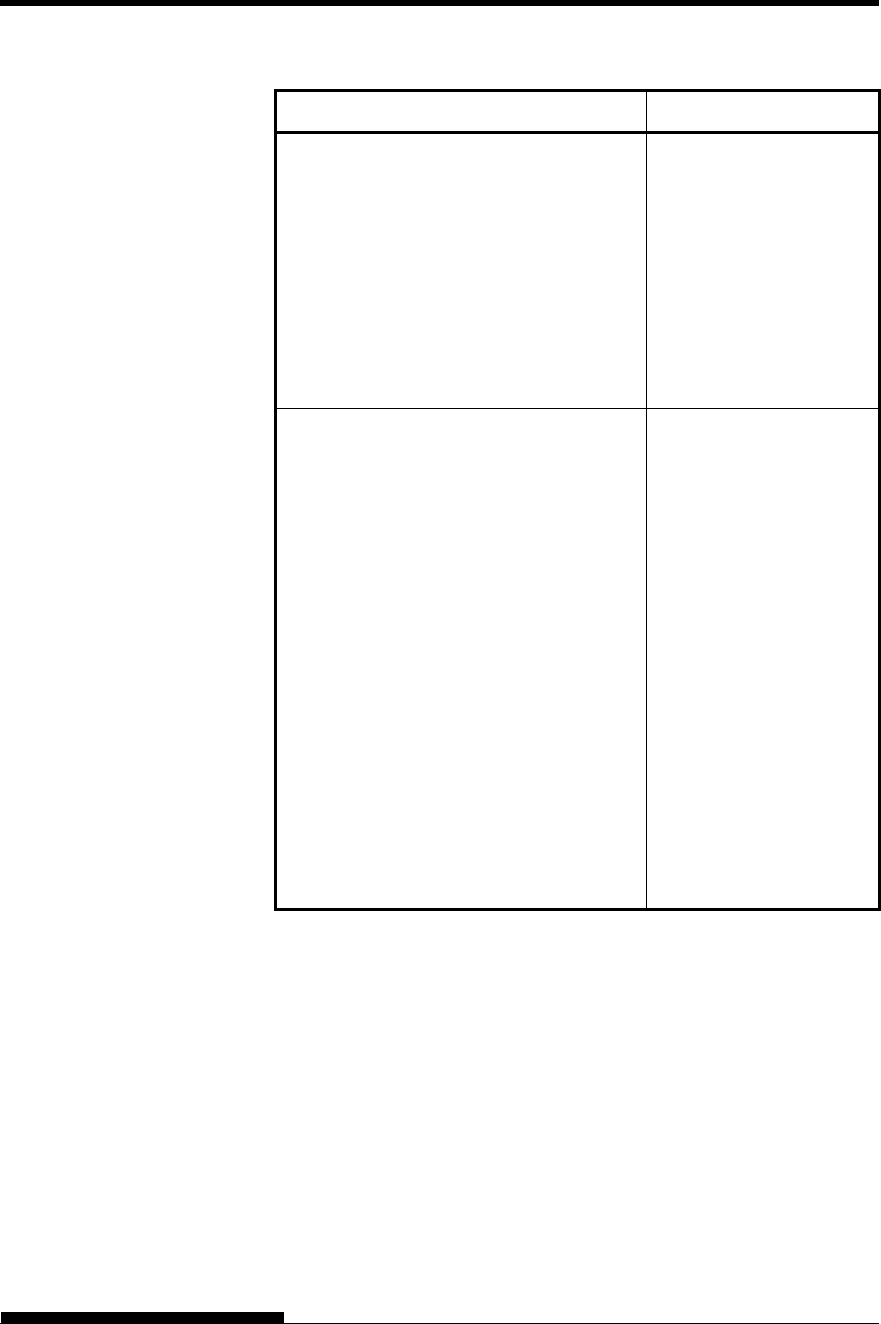
COMMAND SETS
User's Manual C-27
Function Command
Miscellaneous
Sound the bell
Unidirectional printing on/off
(on:n= 1, off:n= 0)
Add a carriage return to all line feeds
(on:n= 1, off:n= 0)
Printer offline
Enter online setup mode
Select default settings
BEL
ESC U (n)
ESC 5 (n)
ESC j
ESC e ONLINE (data)
ESC [ K (n1)(n2)
(i) (ID) (p1)(p2)
Bar Code Printing
Print bar code
b: Total number of parameters
R: (fixed)
c: Type of bar code
w: Width of narrow bar in 1/1440-
inch
units
h: Height of bar code
a: Defines check characters and
OCR
characters
ch1 ... chn: Bar code characters
NOTE
Please refer to the command specification
of DPL24CPLUS for details.
ESC DC4 (b) R
(c) (w) (h) (a)
(ch1) ... (chn)
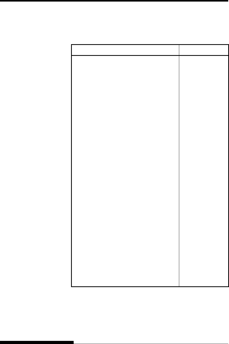
COMMAND SETS (ESC/P2)
C-28 User's Manual
This section describes the printer commands for the Epson ESC/P2
emulation. Asterisks in the “Function” column indicate extended
commands that are not supported by the original printer.
Function Command
Print Mode Control
Double-strike (bold) printing on
Double-strike (bold) printing off
Emphasized (shadow) printing on
Emphasized (shadow) printing off
Italic printing on
Italic printing off
Select character style
n = 0: Normal
1: Outlined
2: Shaded
3: Outlined and shadowed
One-line double-width characters on
One-line double-width characters off
Double-width characters on/off
(on: n= 1, off: n= 0)
Double-height characters on/off
(on: n= 1, off: n= 0)
Condensed characters on
Condensed characters off
Subscript or superscript printing on
(subscript: n= 1, superscript: n= 0)
Subscript and superscript printing off
Underline on/off
(on: n= 1, off: n= 0)
ESC G
ESC H
ESC E
ESC F
ESC 4
ESC 5
ESC q (n)
SO or ESC SO
DC4
ESC W (n)
ESC w (n)
SI or ESC SI
DC2
ESC S (n)
ESC T
ESC - (n)
EPSON ESC/P2
EMULATION
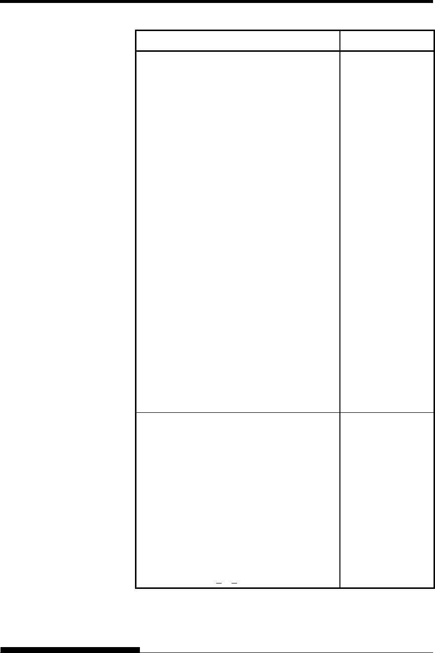
COMMAND SETS
User's Manual C-29
Function Command
Select line
n1 = 3, n2 = 0, d1 = 1
d2 = 0:Ignore command
1:Underline
2:Strike through
3:Overscore
d3 = 0 or 4:Cancel line selection
1:Single line
2 or 3:Double line
5:Single-dotted line
6 or 7:Double-dotted line
Select printing style
This command allows you to combine
various printing styles. The value
of n is the sum of the values of the
styles you want to combine.
n = 0:Pica pitch
1:Elite pitch
2:Proportional spacing
4:Condensed
8:Shadow
16:Bold
32:Double-width
64:Italics
128:Underline
ESC ( - (n1)(n2)
(d1) (d2) (d3)
ESC ! (n)
Horizontal Control
Space
Backspace
Carriage return
Set elite pitch
Set pica pitch
Set 15 CPI
Proportionally spaced characters on/off
(on: n = 1, off: n = 0)
Set inter-character space to n/120 inch (for
draft) or n/180 inch (for letter and
proportional) (0 < n < 127)
SP
BS
CR
ESC M
ESC P
ESC g
ESC p (n)
ESC SP (n)

COMMAND SETS (ESC/P2)
C-30 User's Manual
Function Command
Set character pitch to (n1+ n2 256)/360 inch
(0 < n1 < 255) (0 < n2 < 4)
Select character pitch (specify unit of pitch)
n1 = 1, n2 = 0
d = 10 to 19: 10/3600 inch = 1/360 inch
d = 20 to 29: 20/3600 inch = 1/180 inch
d = 30 to 39: 30/3600 inch = 1/120 inch
d = 40 to 49: 40/3600 inch = 1/90 inch
d = 50 to 59: 50/3600 inch = 1/72 inch
d = 60 to 69: 60/3600 inch = 1/60 inch
ESC c (n1)(n2)
ESC ( U (n1)(n2) (d)
Vertical Control
Line feed
Form feed
Advance paper n/180 inch (1 < n < 255)
Set line spacing to 1/8 inch
Set line spacing to n/180 inch (0 < n < 255)
Set line spacing to n/60 inch (0 < n < 127)
Set line spacing to 1/6 inch
Set line spacing to n/360 inch (0 < n < 255)
LF
FF
ESC J (n)
ESC 0
ESC 3 (n)
ESC A (n)
ESC 2
ESC + (n)
Tabulation
Horizontal tab execution
Set horizontal tabs
The values of n1 to nk in this
command are the ASCII values of the
print columns (at the current character
width) at which tabs are to be set.
(1 < n < 255) (1 < k < 32)
Move print position n/120 inch (for draft)(*1)
or n/180 inch (for letter)(*1) right from
left margin (n = n1+ n2 256)
Move print position n/120(*1) inch (for draft)
Or n/180(*1) inch (for letter) left or right
from the current position
(n = n1+ n2 256)
Vertical tab execution
HT
ESC D
(n1)... (nk) NUL
ESC $ (n1)(n2)
ESC \ (n1)(n2)
VT

COMMAND SETS
User's Manual C-31
Function Command
Set vertical tabs
The values of n1 to nk in this
command are the ASCII values of the
lines (at the current line spacing)
at which tabs are to be set.
(1 < n < 255) (1 < k < 16)
Move to dot line (d1 + d2 256)/360(*1) inch
n1 = 2, n2 = 0
(0 < d1 < 255) (0 < d2 < 127)
Vertical relative move by (d1 + d2 256)/360(*1)
Inch
n1 = 2, n2 = 0
(0 < d1 < 255) (0 < d2 < 127)
-32768 < d1 + d2 256 32768
ESC B (n1)...
(nk) NUL
ESC ( V (n1) (n2)
(d1) (d2)
ESC ( v (n1) (n2)
(d1) (d2)
Page Formatting
Set right margin to column n
(1 < n < 255)
Set left margin to column n
(0 < n < 255)
Set top and bottom margins from top of page
n1 = 4, n2 = 0
Top margin = (t1 + t2 256)/360(*1) inch
(0 < t1 < 255) (0 < t2 < 127)
Bottom margin = (b1+b2 256)/360(*1) inch
(0 < b1< 255)
(0 < b2 < 127)
Set perforation skip by n lines
(1 < n < 127)
Perforation skip off
Set page length to n lines (1 < n < 127)
Set page length to n inches (1 < n < 22)
Set page length to (d1 + d2 256)/360(*1) inch
n1 = 2, n2 = 0
(0 < d1< 255) (0 < d2 < 127)
ESC Q (n)
ESC l (n)
ESC ( c (n1) (n2)
(t1) (t2) (b1) (b2)
ESC N (n)
ESC O
ESC C (n)
ESC C NUL (n)
ESC ( C (n1) (n2)
(d1) (d2)
*1 The value depends on the pitch set by the ESC (U command.
The default is 1/360 inch.
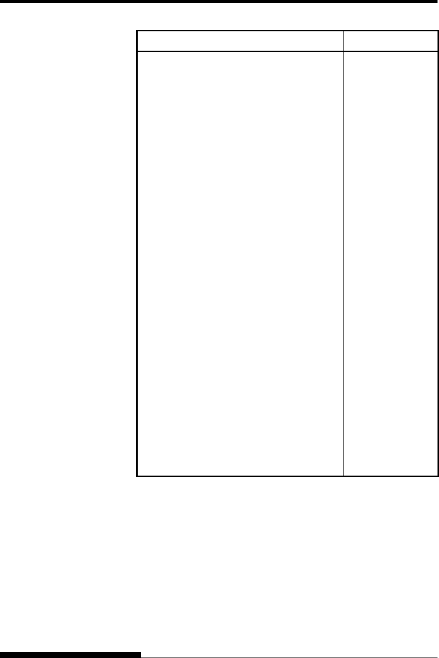
COMMAND SETS (ESC/P2)
C-32 User's Manual
Function Command
Character Set Control
Select character set 1
Select character set 2
Select character set table
n = 0:Italics character set
1:Graphics character set
2:Downloaded character set
3:Graphics character set
Select international character set
n = 0:USA
1:France
2:Germany
3:United Kingdom
4:Denmark 1
5:Sweden
6:Italy
7:Spanish 1
8:Japan
9:Norway
10:Denmark 2
11:Spanish 2
12:Latin America
13:Korea
64:Legal
ESC 7
ESC 6
ESC t (n)
ESC R (n)

COMMAND SETS
User's Manual C-33
Function Command
Assign a character set to active character set
number 0 to 3
n1 = 3, n2 = 0
d1 = 0:Active character set number 0
1:Active character set number 1
2:Active character set number 2
3:Active character set number 3
d2 = 0:Italic
1:PC 437 (USA)
3:PC 850 (Multilingual)
7:PC 860 (Portugal)
8:PC 863 (Canada-French)
9:PC 865 (Norway)
d3 = 0
Print n1+ n2 256 characters from all-
character set
(0 < n1 < 255) (0 < n2 < 127)
(0 < n1 + n2 256 < 255)
(0 character codes < 254)
Clear input buffer
Delete a character
Force most significant bit to 1
Force most significant bit to 0
Cancel control over most significant bit
ESC ( t (n1) (n2)
(d1) (d2) (d3)
ESC ( ^ (n1)(n2)
(character codes)
CAN
DEL
ESC >
ESC =
ESC #
Font Selection and Downloading
Select font
n = 0:Resident character set
1:Downloaded character set
Select letter or draft quality
n = 0:Draft
1:Letter
ESC % (n)
ESC x (n)
COMMAND SETS (ESC/P2)
C-34 User's Manual
Function Command
Select type style
Bitmap font:
n = 0:Courier
1:Courier
2:Courier
3:Prestige
4:Courier
5:OCR-B
6:OCR-A
7:Courier
8:Courier
9:Courier
Scalable font:
n = 0:Timeless
1:Nimbus Sans
2:Courier
3:Timeless
4:Timeless
5:Timeless
6:Timeless
7:Timeless
8:Timeless
9:Timeless
Set scalable font mode
m sets character pitch.
m = 0:Keep previous pitch
1:Set proportional space mode
m > 5:Select character pitch
(m/360 inch)
(Reset proportional space mode)
n1 and n2 set point size of font.
Point size = (n1 + n2 256) 0.5 point
(0 < n1 < 255) (0 < n2 < 127)
Copy resident character set to download area
Create download font
ESC k (n)
ESC X m (n1)(n2)
ESC : NUL(n)(s)
ESC & NUL (n1)(n2)
(d0) (d1) (d2) (data)
* Indicates extended commands not supported by the original printer.
COMMAND SETS
User's Manual C-35
Function Command
Bit Image Graphics
Graphics type m graphics
Bit image mode definition
Single-density graphics
Double-density graphics
High-speed double-density graphics
Quadruple-density graphics
Select raster image graphics
n1 = 1, n2 = 0
d= 1: Raster image graphics mode
Print raster image graphics
ESC * (m) (n1)(n2)
(data)
ESC ? (s) (n)
ESC K (n1)(n2) (data)
ESC L (n1)(n2) (data)
ESC Y (n1)(n2) (data)
ESC Z (n1)(n2) (data)
ESC ( G (n1)(n2) (d)
ESC . (c)(v) (h) (m)
(n1)(n2) (data)
Cut Sheet Feeder Control
Feed a sheet from bin 1
Feed a sheet from bin 2
Feed a sheet from bin 3
Eject a page from the printer
Select bin 1 for following pages
Select bin 2 for following pages
Select bin 3 for following pages
Change bins at next page
ESC EM 1
ESC EM 2
ESC EM E
ESC EM R
/ / 1 / /
/ / 2 / /
/ / E / /
/ / C / /
Print Option Control
Friction feed selection
Rear tractor feed selection
Front tractor feed selection
Cut sheet feed selection
Host controlled paper path control
n = “F” :Friction
“T” :Rear Tractor
“M” : Front Tractor
Automatic paper thickness control
/ / F / /
/ / T / /
/ / M / /
/ / S / /
ESC e T (n)
ESC e P (n1) (n2) (n3)
(n4)
COMMAND SETS (ESC/P2)
C-36 User's Manual
Function Command
Miscellaneous
Sound the bell
Move print head to home position
Unidirectional printing on/off
(on:n = 1, off:n = 0)
Initialize printer
Enter online setup mode
BEL
ESC <
ESC U (n)
ESC @
ESC e ONLINE
(data)
Bar Code Printing
Print bar code
b: Total number of parameters
R: (fixed)
c: Type of bar code
w: Width of narrow bar in 1/1440-inch
units
h: Height of bar code
a: Defines check characters and OCR
characters
ch1 ... chn: Bar code characters
NOTE
Please refer to the command specification of
DPL24CPLUS for details.
ESC DC4 (b) R
(c) (w) (h) (a)
(ch1) ... (chn)

User's Manual D-1
D
APPENDIX D INTERFACE INFORMATION
INTERFACE INFORMATION
This printer can communicate with a computer
through a Centronics parallel interface, a RS-232C
serial interface, a USB interface, or a LAN interface. You can specify
the interface selection mode so that the printer uses which interface or it
can automatically select the interface from which it first receives data.
This appendix provides information you may need for wiring your own
interface cables or for programming computer-to-printer communications.
Most users do not need the information in this appendix. To simply
connect your printer to your computer, follow the instructions in Chapter
2.
This parallel interface can operate in the following two modes:
Unidirectional (forward channel) mode or conventional mode: This
printer supports a conventional Centronics interface.
Bidirectional (forward/reverse channel) mode or nibble mode: This
printer supports a bidirectional communication per Nibble mode of
the IEEE 1284 Standard.
The cable connector at the printer side should be a shielded, Amphenol
DDK 57FE-30360 or equivalent.
The connector pin assignments are given in the following tables by
modes. In the tables:
“Input” denotes a signal from the computer to the printer.
“Output” denotes a signal from the printer to the computer.
The return lines specified in the second column represent
twisted pairs, with one side connected to signal ground.
The standard signal levels are 0.0 to +0.4 V (low), and +2.4 to
+5.0 V (high).
PARALLEL
INTERFACE
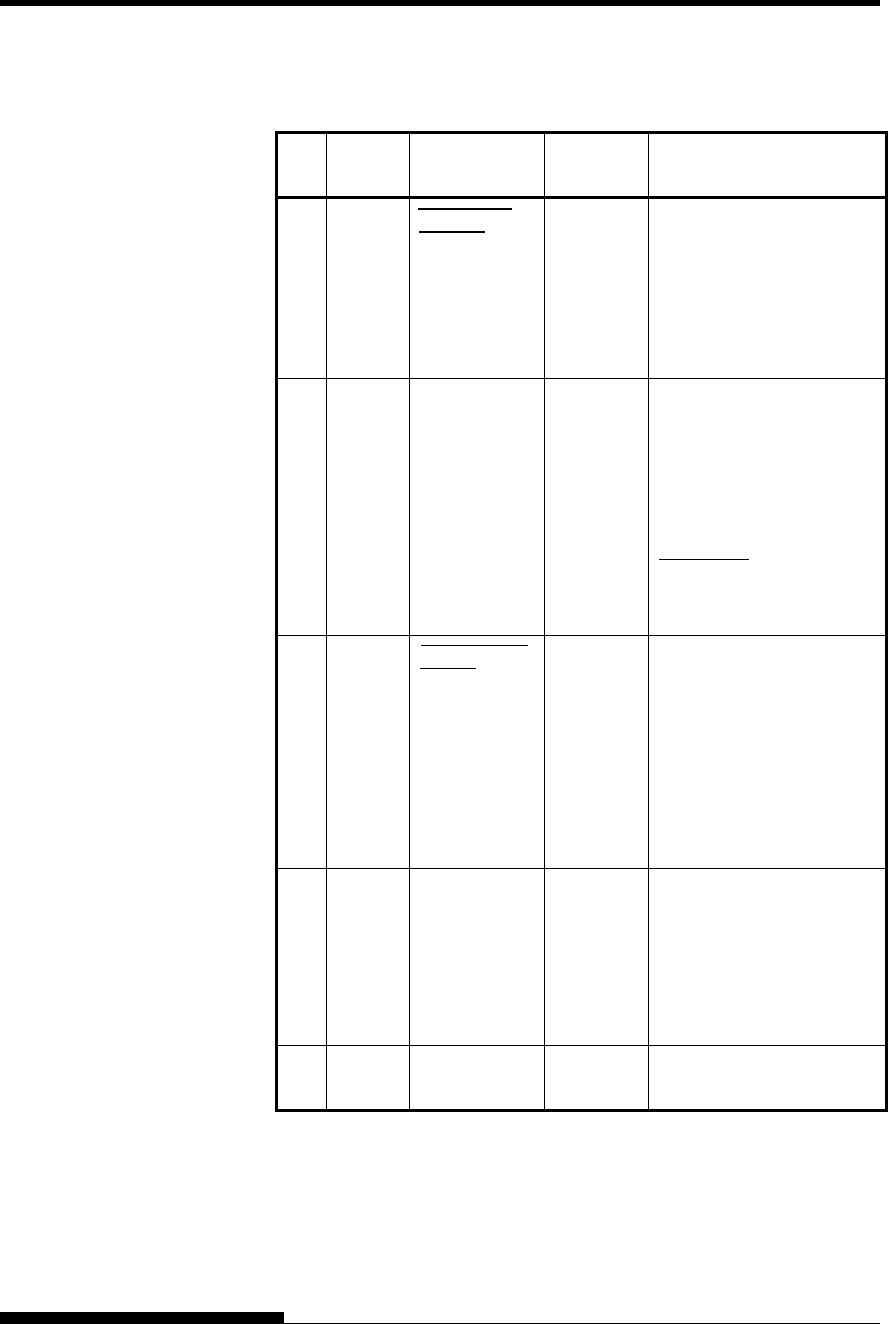
INTERFACE INFORMATION
D-2 User's Manual
Compatible Mode
Pin
No. Return
Pin No. Signal Name Direction Description
1 19 Data Strobe
(DSTB)
Input This signal is a strobe
pulse for reading data
(Data 1 to 8). The printer
reads data when this signal
is low. The pulse width
must be 1 s or more at
the receiving terminal.
2-9 20-27 Data 1 to 8 Input Data 8 (pin 9) is the most
significant bit; however,
this pin is not used in 7-bit
ASCII communications.
Logical 1 signals must go
high at least 1 s before
the falling edge of the
Data Strobe signal and
must stay high for at least
1 s after the rising edge.
10 28 Acknowledge
(ACK)
Output This pulse signal indicates
that the printer has
received data and is ready
to accept the next set of
data.
This signal is also sent
when the printer is
switched from offline to
online.
11 29 Busy Output Data cannot be received
when this signal is high.
This signal is high during
data entry, when the
printer is offline, when the
buffer is full, or when an
error occurs.
12 30 Paper Empty
(PE)
Output This signal is high when
the printer is out of paper.
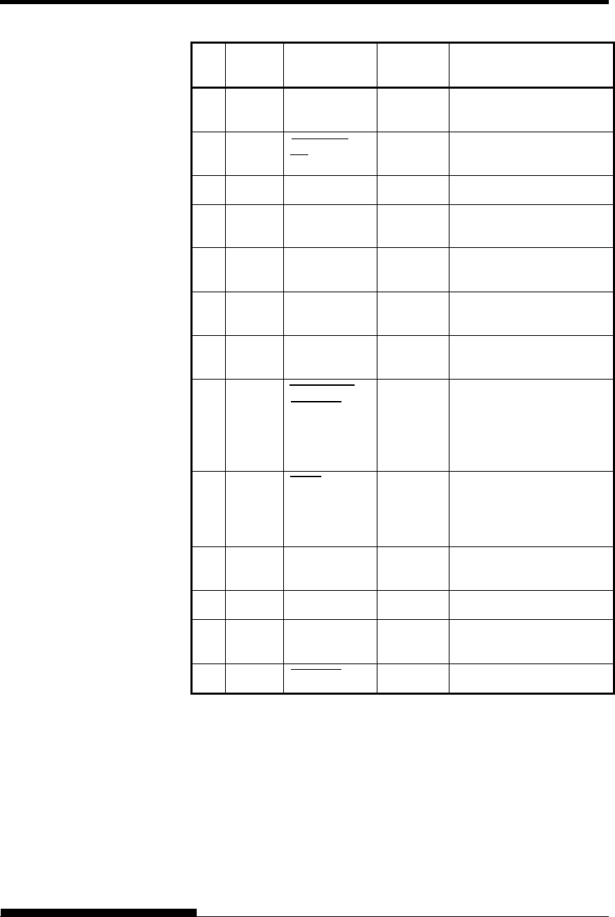
INTERFACE INFORMATION
User's Manual D-3
Pin
No. Return
Pin No. Signal Name Direction Description
13 Select
(SLCT)
Output This signal is high when
the printer is online.
14 Auto Feed
XT
Input Not used
15 No connection
16 Signal
Ground
Logic ground level (0 V)
17 Frame
Ground
Printer chassis ground line.
FG and SG are connected.
18 +5 V Output +5 V source (up to 300
mA)
19-
30
Signal
Ground
Twisted pair return lines
31 Input Prime
(INPRM)
If this signal is low for
more (INPRM) than 50 s,
the printer is reset to the
initial condition and is
placed online.
32 Fault Output This signal is low when
the printer is offline, paper
is out, or when there is a
printer error.
33 Signal
Ground
Logic ground level (0 V)
34 No connection
35 +5 VR Output Pulled up to +5 V through
a 3.3 k resistor
36 SLCT-IN Input Not used
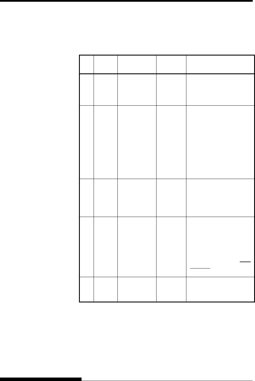
INTERFACE INFORMATION
D-4 User's Manual
Nibble Mode
Pin numbers 2 to 9, 15 to 31, and 33 to 35 are the same as the
conventional mode.
Pin
No. Return
Pin No. Signal Name Direction Description
1 19 Host Clock Input This signal is set high
when the host requests the
reverse data transfer phase
(nibble mode).
10 28 Printer Clock Output Reverse data transfer
phase:
This signal goes high
when data being sent to the
host is established.
Reverse idle phase:
This signal is set low then
goes high to interrupt the
host, indicating that data is
available.
11 29 Printer Busy Output Reverse data transfer
phase:
Data bit 3, data bit 7, then
forward path (host to
printer) busy status
12 30 Ack Data Req Output Reverse data transfer
phase:
Data bit 2, then data bit 6
Reverse idle phase:
This signal is set high until
the host requests data and,
after that, follows the Data
Available signal.
13 X Flag Output Reverse data transfer
phase:
Data bit 1, then data bit 5
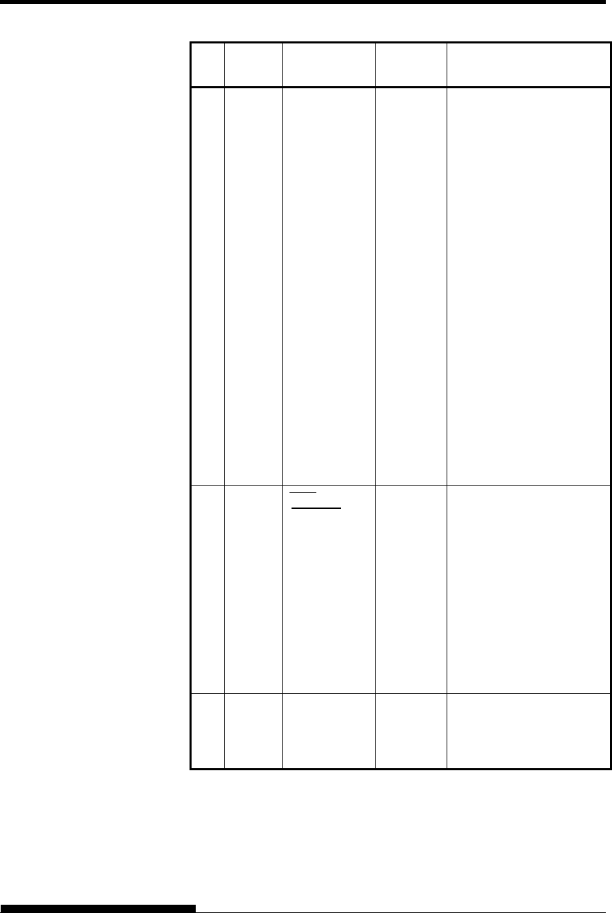
INTERFACE INFORMATION
User's Manual D-5
Pin
No. Return
Pin No. Signal Name Direction Description
14 Host Busy Input Reverse data transfer
phase:
This signal is set low when
the host can receive data,
and goes high when the
host has received data.
Following a reverse data
transfer, the interface
enters the reverse idle
phase when the Host Busy
signal goes low and the
printer has no data.
Reverse idle phase:
This signal goes high
when the Printer Clock
signal goes low so that the
interface re-enters the
reverse data transfer phase.
If it goes high with the
1284 Active signal low,
the 1284 idle phase is
aborted and the interface
returns to the compatibility
mode.
32 Data
Available
Output Reverse data transfer
phase:
This signal is set low when
the printer is ready to send
data to the host. During
the data transfer, it is used
as data bit 0 (LSB), then
data bit 4.
Reverse idle phase:
This signal is used to
indicate that data is
available.
36 1284 Active Input This signal goes high to
cause the printer to enter
the reverse data transfer
phase (nibble mode).
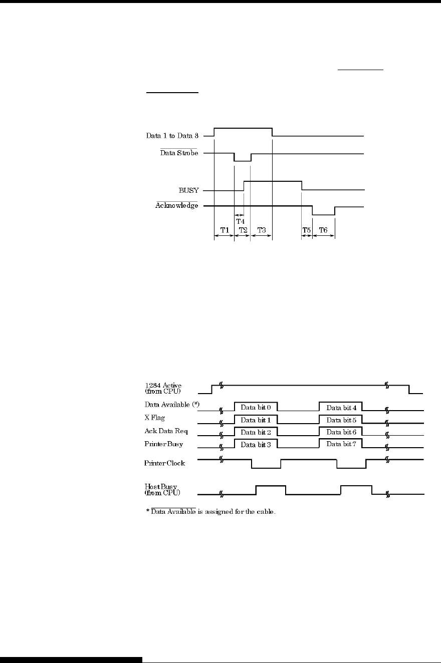
INTERFACE INFORMATION
D-6 User's Manual
Data Transmission Timing
In unidirectional mode (conventional Centronics interface), this printer
guarantees the received data when the Data and Data Strobe signals from
the computer have the following timing with respect to the Busy and
Acknowledge signals from the printer.
T1, T2, T3 > 1 s
T4 < 1 s
0 s < T5 < 3 s
2 s < T6 < 6 s
In bidirectional mode (nibblemode), this printer can send data to the
computer. Data is sent in units of four bits (nibble) using four output
signal lines as data paths. The following outlines one byte of data sent
during reverse data transfer phase in nibble mode.
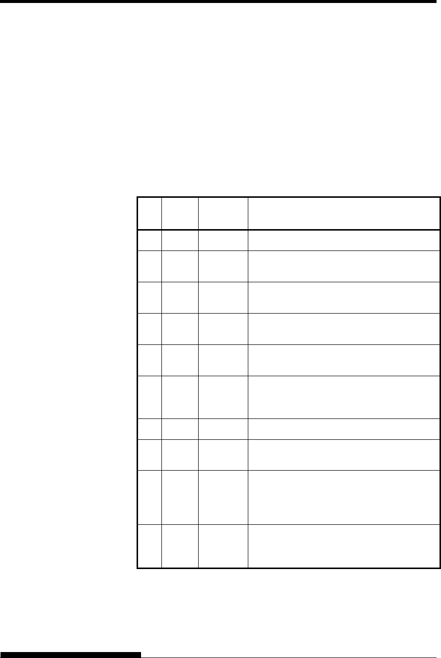
INTERFACE INFORMATION
User's Manual D-7
RS-232C is the standard serial interface for data terminal equipment. The
cable connector at the printer side should be a D-subminiature Cannon or
Cinch DB-25P male connector or equivalent that conforms to EIA
standards.
The table that follows shows the pin assignments commonly used by
most computers. In the table:
“Input” denotes a signal from the computer to the printer.
“Output” denotes a signal from the printer to the computer.
The signal level for mark state (logical 1) is -3 V or lower; for
space state (logical 0), it is +3 V or higher.
Pin
No. Signal
Name Direction Description
1 FG Frame Ground
2 TD Output This pin carries information from the printer
to the computer.
3 RD Input Received Data. This pin carries information
from the computer to the printer.
4 RTS Output Request To Send. Spaces are sent when the
printer is ready to transmit data.
5 CTS Input Clear To Send. Spaces are sent when the
computer is ready to receive data.
6 DSR Input Data Set Ready. Spaces are sent when the
computer has been powered on and is ready
to receive or transmit data.
7 SG Signal Ground (common return)
8 CD Input Carrier Detect. Spaces are sent when the
computer allows the printer to receive data.
11 RC Output Reverse Channel. This signal is used instead
of the DTR signal in the RC protocol.
Spaces are sent when the printer is ready to
receive or transmit data.
20 DTR Output Data Terminal Ready. Spaces are sent when
the printer has been powered on and is ready
to receive or transmit data.
SERIAL INTERFACE

INTERFACE INFORMATION
D-8 User's Manual
Serial Options
The serial options for the computer and the printer must match. Use the
printer control panel, the computer operating system, or your software to
change options specified as “selectable.”
Transmission mode: Asynchronous, full duplex, or half duplex
(selectable)
Speed: 150, 300, 600, 1200, 2400, 4800, 9600, or
19200 baud (selectable)
Data bits: 7 or 8 bits (selectable)
Parity bit: Odd, even, mark, space, or none (selectable)
Start bit: 1 bit
Stop bit: 1 or 2 bits (selectable)
Protocol: XON/XOFF (DC1/DC3), DTR (Data Terminal
Ready), or RC (Reverse Channel) (selectable)
Buffer size: 256, 2K, 8K, 24K, 32K, 96K, or 128K bytes
(selectable)
Cable Wiring
This printer allows two types of serial communication control: DSR-
enabled and DSR-disabled. The type of control required is determined
by your computer requirements. The type of control also affects the way
the interface cable is wired. To determine whether you need DSR-
enabled control or DSR-disabled control, use the printer HARDWRE
function (see Chapter 5).
DSR-disabled control offers simpler cabling and communication than
DSR-enabled control. DSR-disabled control can be used to interface
with an IBM PC and most other personal computers. With DSR-disabled
control, the input control signals DSR, CTS, and CD are always
considered high, regardless of their actual states. Therefore, no wire
connection for these pins is required. The following figure shows the
wiring required for connection to an IBM PC.
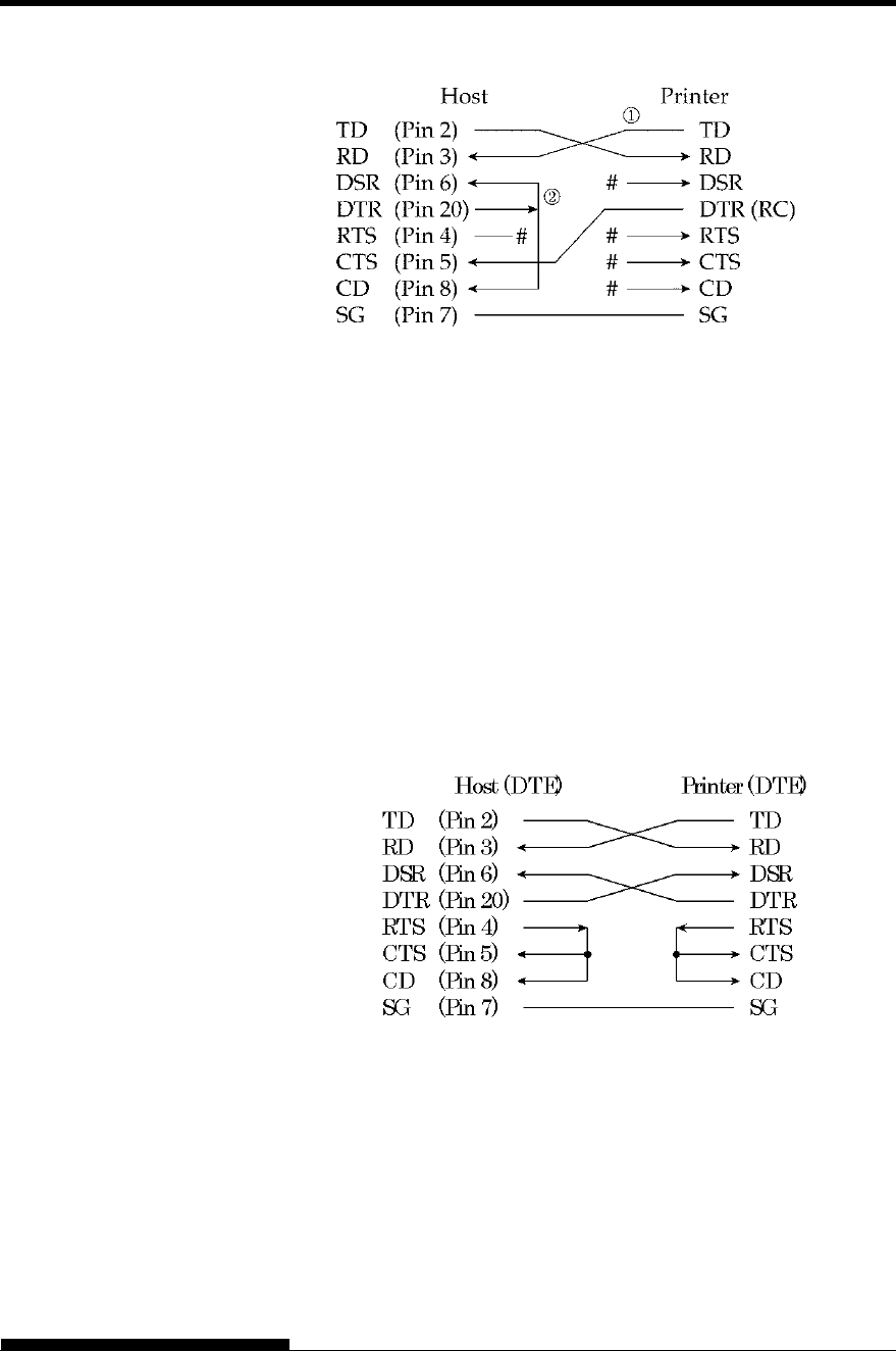
INTERFACE INFORMATION
User's Manual D-9
# indicates an open wire.
Wire q is unnecessary for the DTR (or RC) protocol.
Some computers may not require wire w.
DSR-enabled control enables communication using an RS-232C
interface. The CTS and DSR input control signals are enabled; CD is
ignored. DSR must be high when the printer receives data. If the printer
has data to be transmitted to the computer, the printer transmits the data
when both DSR and CTS are high.
When using DSR-enabled control, use a straight-through cable to
connect to a DCE (data communications equipment) device. Use a null-
modem cable to connect to a DTE (data terminal equipment) device, as
shown below.
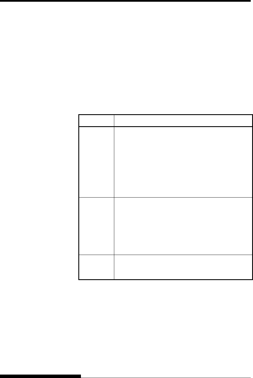
INTERFACE INFORMATION
D-10 User's Manual
Serial Protocols
A protocol is a set of instructions that control the way data is transmitted
between devices such as a computer and printer. The protocol ensures
that the computer does not send information to the printer faster than the
information can be processed. By telling the computer when the printer
can receive data, the protocol prevents the printer s buffer from
overflowing.
This printer offers a choice of four different protocols for connection to a
variety of computers: XON/XOFF, DTR, and RC. If you computer
documentation does not recommend a particular protocol, try DTR. The
following table describes the three protocols.
Protocol Description
XON/XOFF
(DC1/DC3)
When the printer is ready to receive data, it sends the
XON (DC1) code (hex 11). When fewer than 255 bytes
of space remain in the buffer (or when the printer is taken
offline), the printer sends the XOFF (DC3) code (hex 13).
(When the input buffer is configured for 256 bytes, the
buffer limit is reduced from 255 bytes to 63 bytes.) The
computer must stop transmitting data within 255 (63)
characters of receiving the XOFF code, or information
may be lost. If paper runs out, the printer sends an NAK
code (hex 15).
DTR DTR is a hardware protocol; that is, the DTR signal on
interface cable pin 20 is used to control the flow of data
rather than transmission of a character code. When the
printer is ready to receive data, pin 20 is high. When
fewer than 255 (63) bytes of space remain in the buffer
(or when the printer is taken offline), pin 20 is low. The
computer must stop transmitting data within 255 (63)
characters of DTR being low, or information may be lost.
RC The RC protocol is the same as the DTR protocol, except
that the Reverse Channel signal (pin 11) is used instead of
the Data Terminal Ready signal (pin 20).
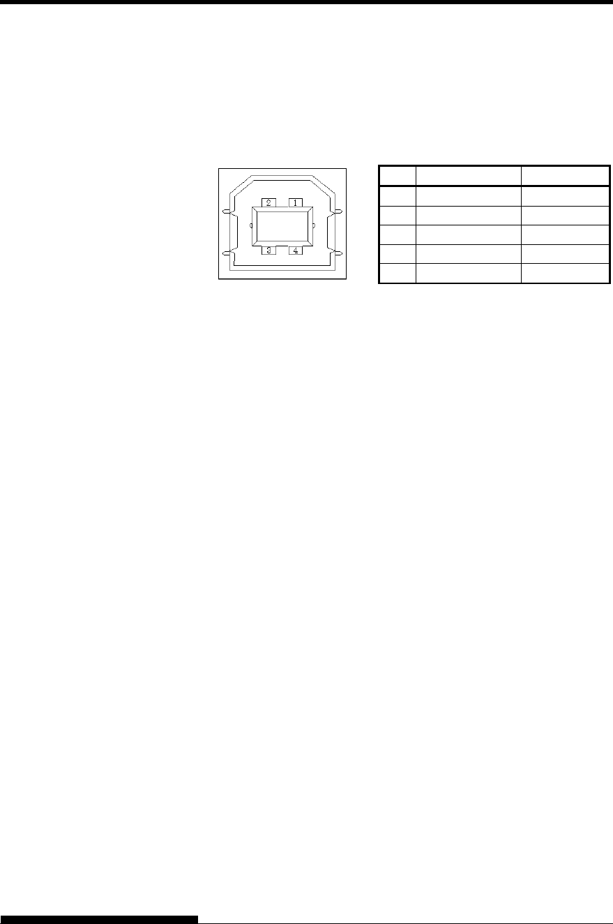
INTERFACE INFORMATION
User's Manual D-11
Cable
This printer supports the USB2.0 Full speed specification. To connect to
the host, use USB 2.0-compliant INF cables (5 meters (196 inch) or
shorter). (Use the shielded cables.)
Connector pin alignment
No. Signal line name Function
1 VBUS Power supply
2 D- Data transfer
3 D+ Data transfer
4 GND Signal ground
Shell Shield
- Connector specification
Printer side
Cable side
Type B receptacle (female)
Upstream port
Type B plug (male)
Specification
- Basic specification USB interface compliant
Note
It does not guarantee all operations on hosts.
- Power control Self-power device
- Transmission mode Full speed (Maximum 12 Mbps
+0.25%)
USB INTERFACE
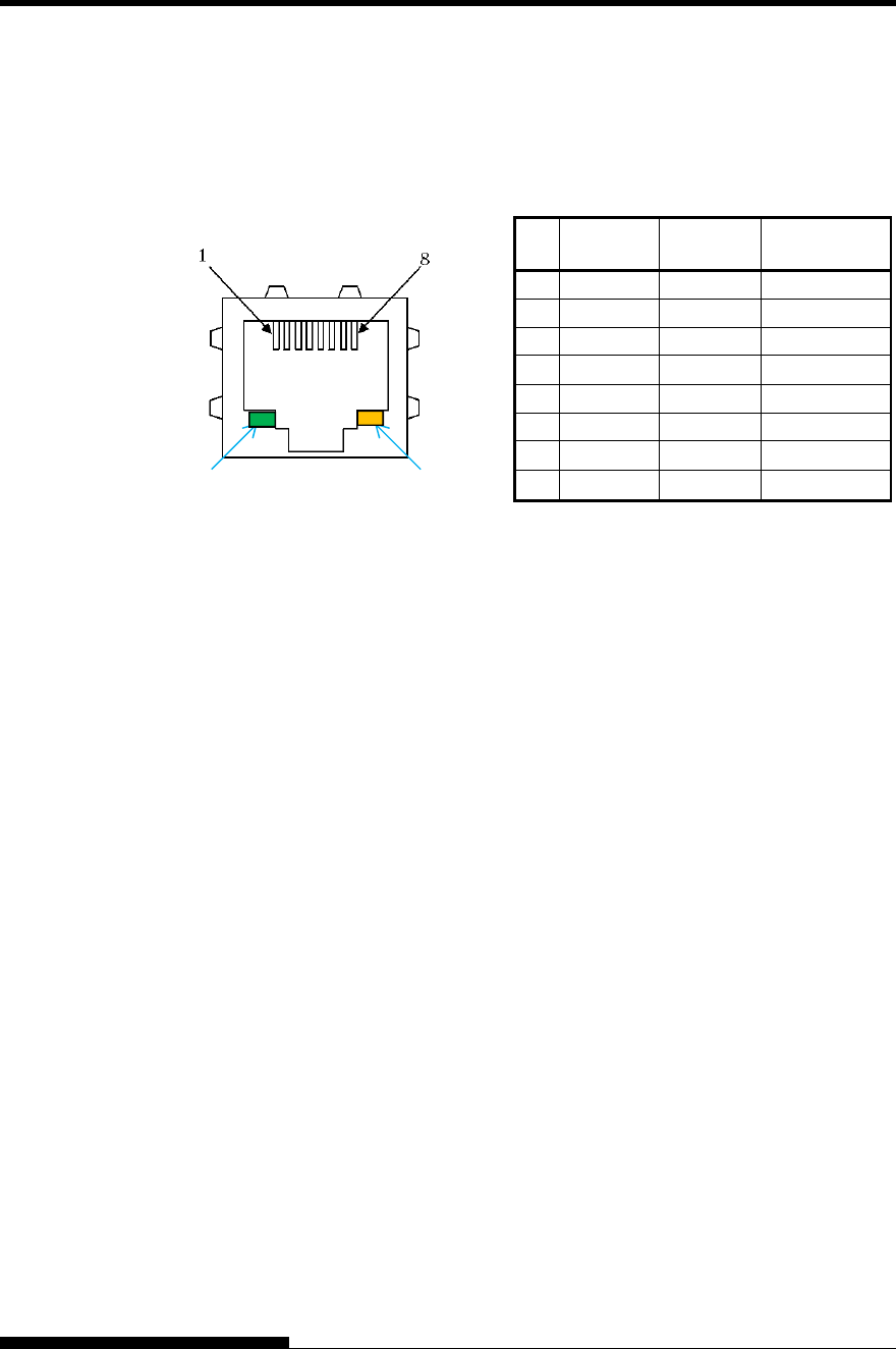
INTERFACE INFORMATION
D-12 User's Manual
Cable
This printer supports the 10Base-T and 100Base-TX cables.
Connector pin alignment No. Signal line
name
DIR Function
1 TXO+ NIC-HUB Transmit data +
2 TXO- NIC-HUB Transmit data -
3 RXI+ HUB-NIC Receive data +
4
5
6 RXI- HUB-NIC Receive data -
7
8
Green LED: 100Mbps
Amber LED: Link/Act
Specification
- Ethernet specifications
Standard: IEEE802.3 10BASE-T,
IEEE802.3u 100BASE-TX
Speed: 100Mbps/10Mbps
Auto negotiation
Duplex: Full/Half
Auto negotiation
MDI/MID-X: Auto negotiation
- Internet protocol specifications
Link layer: ARP
Internet layer: IPv4, ICMPv4
Transport layer: TCP, UDP
Application layer: #9100 RAW, LPD, FTP,
HTTP, SNMP, DHCP
Note
It does not guarantee all operations on hosts.
LAN INTERFACE
Green LED Amber LED
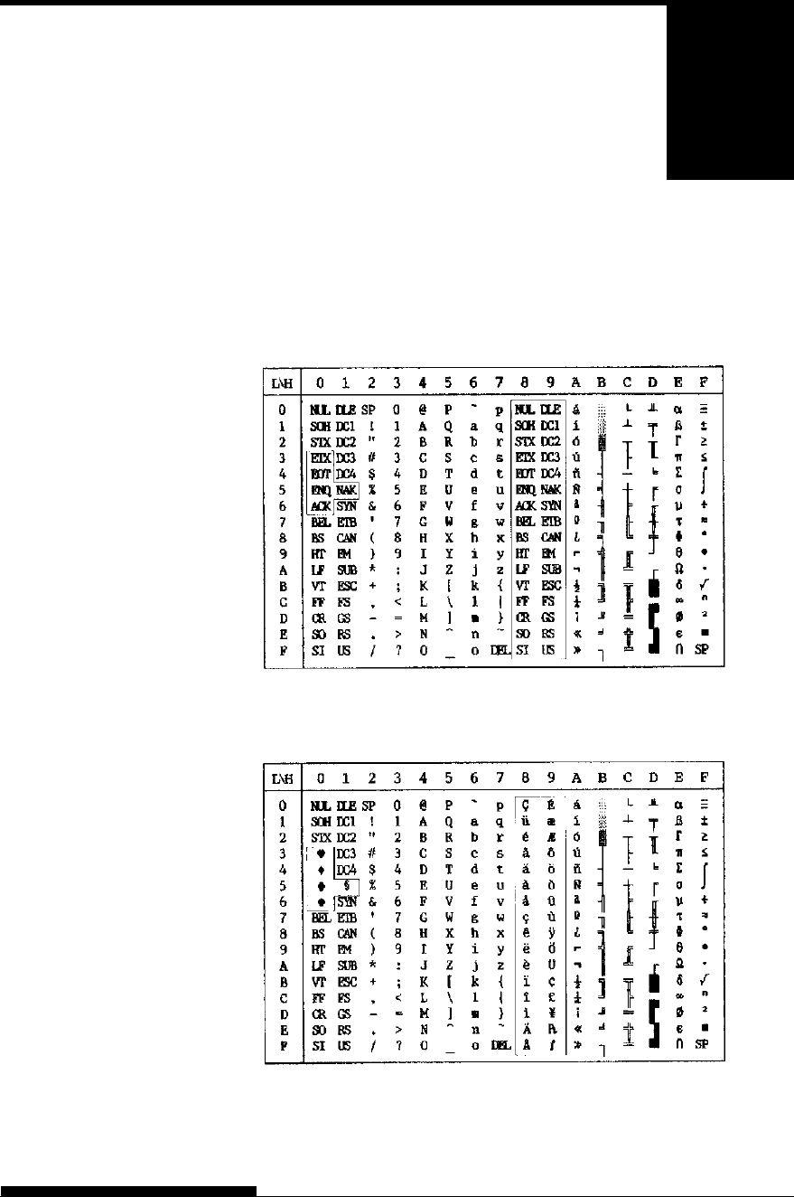
User's Manual E-1
E
APPENDIX E CHARACTER SETS
CHARACTER SETS
Below are character sets 1 and 2 of Code Page 437,
available in the DPL24C PLUS command set and
the IBM Proprinter XL24E emulation. Characters
enclosed in boxes differ for sets 1 and 2.
Characters in set 2 also vary with the national character set.
Code Page 437 is for the USA character set.
Code Page 437 Character Set 1
Code Page 437 Character Set 2
CHARACTER SETS
1 AND 2
(DPL24C PLUS AND
IBM XL24E
EMULATION)
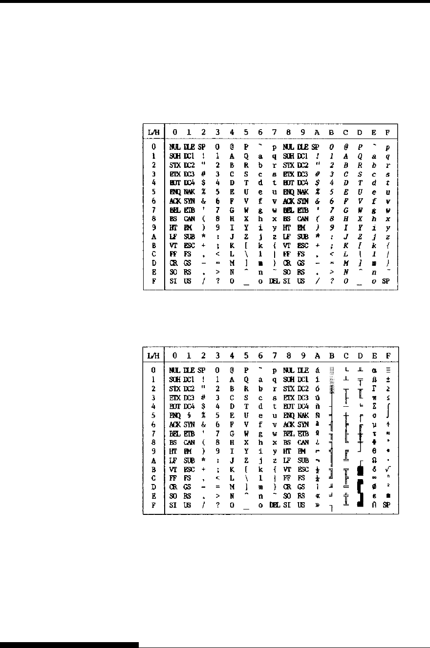
CHARACTER SETS
E-2 User's Manual
The following shows character sets available in the Epson ESC/P2
emulation. Characters differ in codes 128 to 255 (hex 80 to FF).
Italic Character Set
Graphics Character Set 1
ITALIC AND
GRAPHICS
CHARACTER SETS
(ESC/P2
EMULATION)
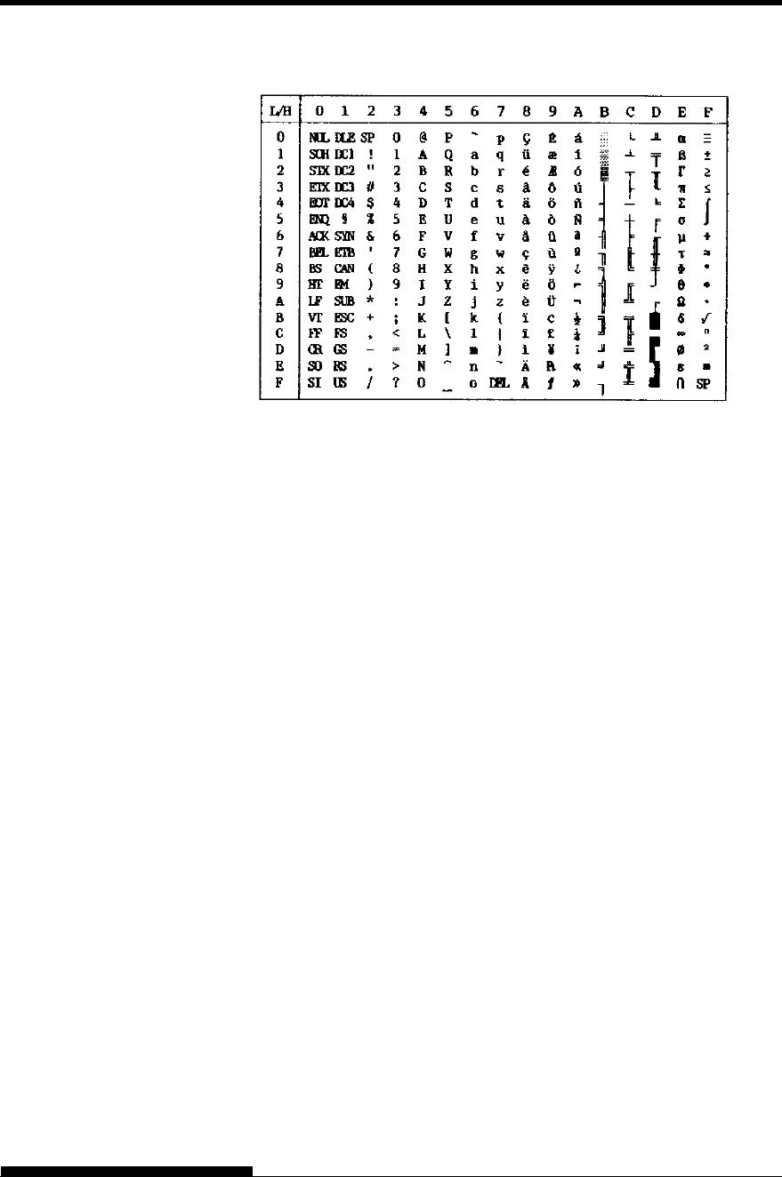
CHARACTER SETS
User's Manual E-3
Graphics Character Set 2
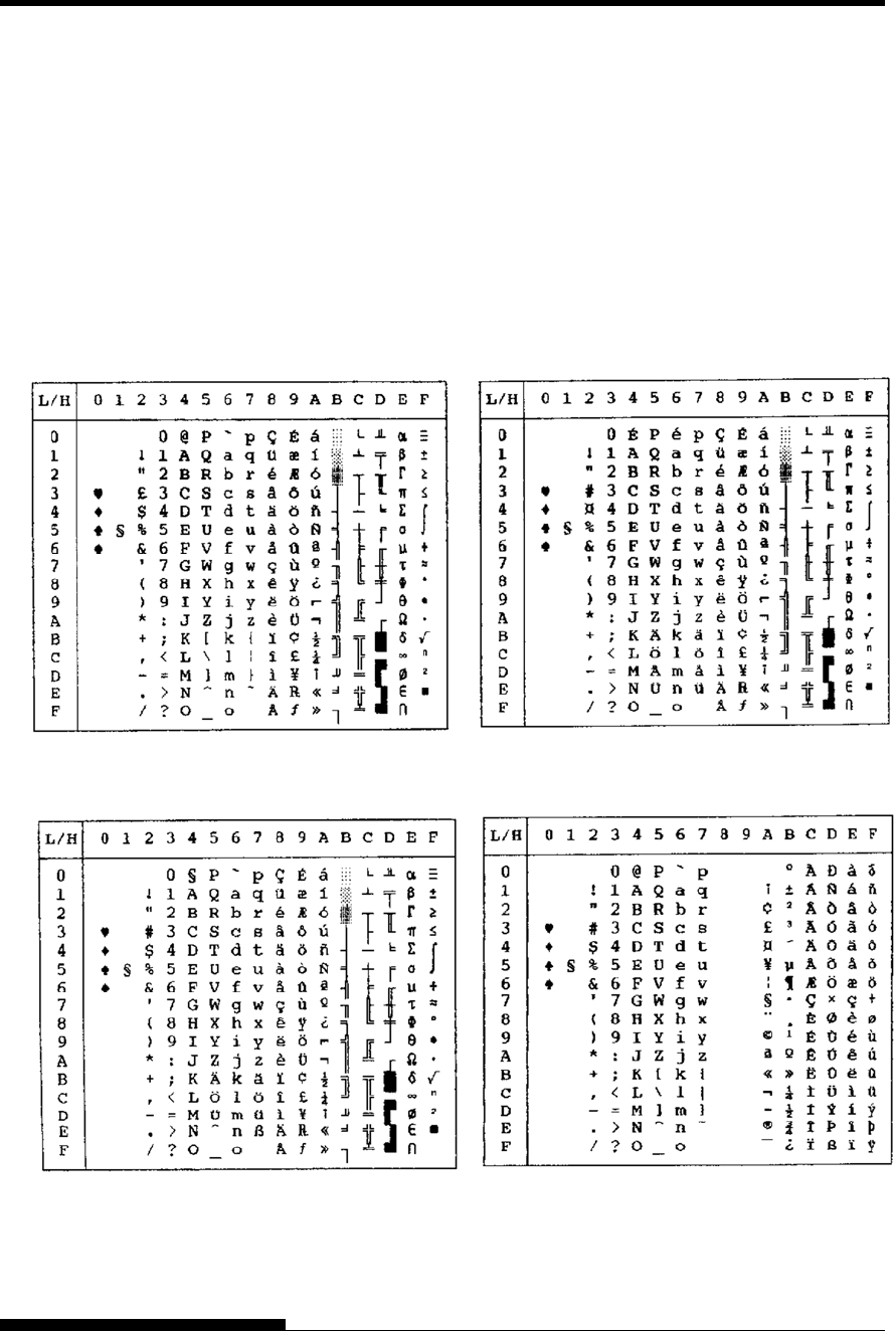
CHARACTER SETS
E-4 User's Manual
Below are the 52 national character sets available for all emulations of
this printer. These character sets support different characters and
symbols specific to different languages. Note that these tables are for
Courier 10, a resident font, and that some national character sets do not
have some characters and symbols whose use depends on resident fonts.
For details, see the table at the end of this appendix.
When the following character sets are used with the Epson ESC/P2
emulation, the printing of FFh code characters is not supported.
ECMA94, ISO8859, ISO-LTN, ISO-TUK, CYRILIC, LATIN-9
NATIONAL
CHARACTER SETS
(ALL EMULATIONS)
UK (British English) S
W
EDISH (Swedish)
GERMAN (German) ISO8859/ECMA94 (ISO 8859-1/ECMA94)
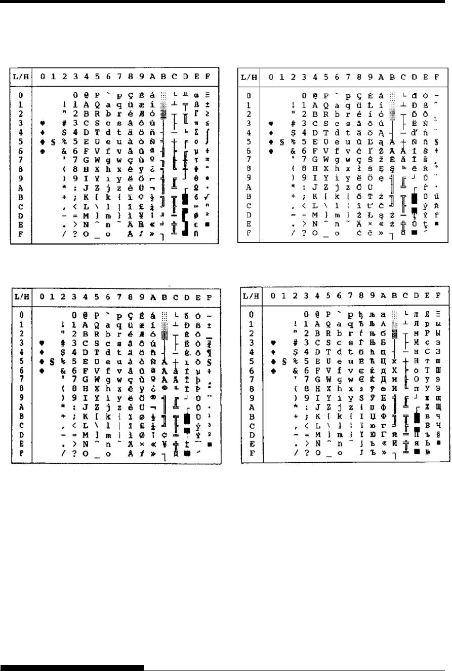
CHARACTER SETS
User's Manual E-5
PAGE437/USA (Code Page 437/USA) PAGE852/PG852-T (Code Page 852)
PAGE850 (Code Page 850(Multilingual)) PAGE855 (Code Page 855)
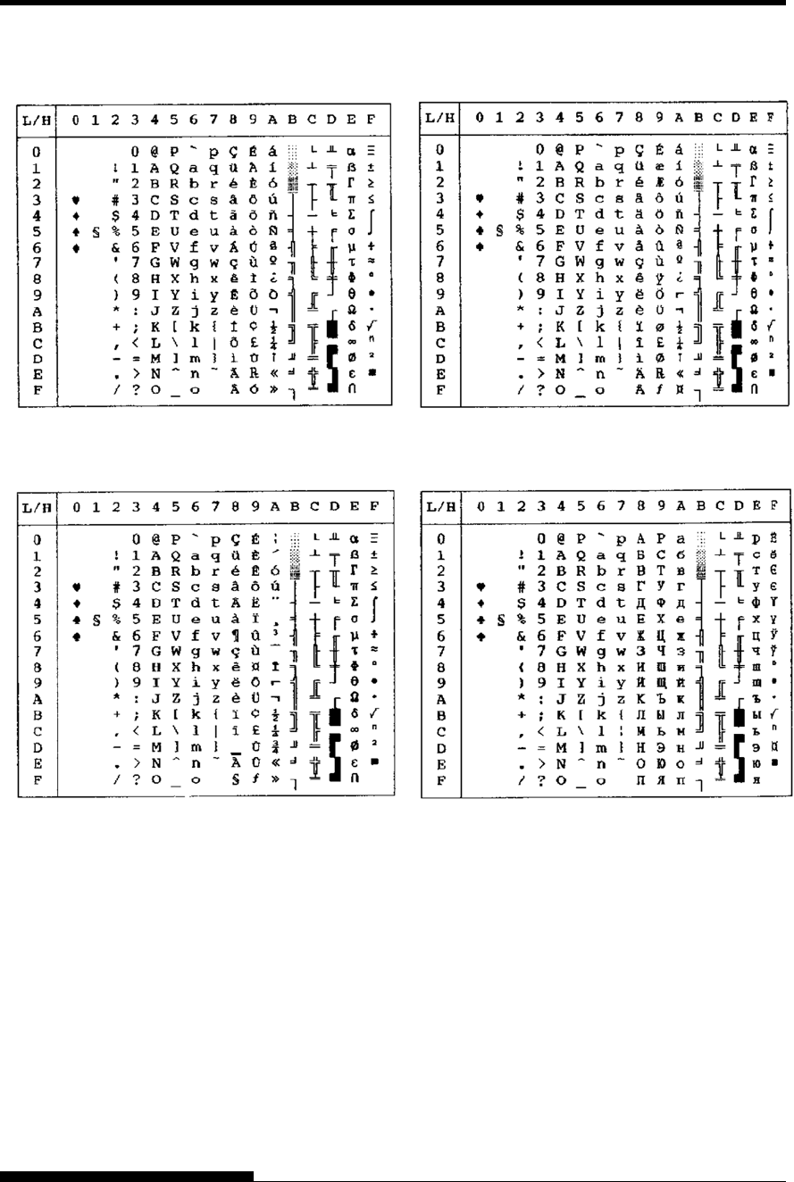
CHARACTER SETS
E-6 User's Manual
PAGE860 (Code Page 860(Portugal)) PAGE865 (Code Page 865(Nordic))
PAGE863 (Code Page 863(Canada-French)) PAGE866 (Code Page 866(Cyrillic))
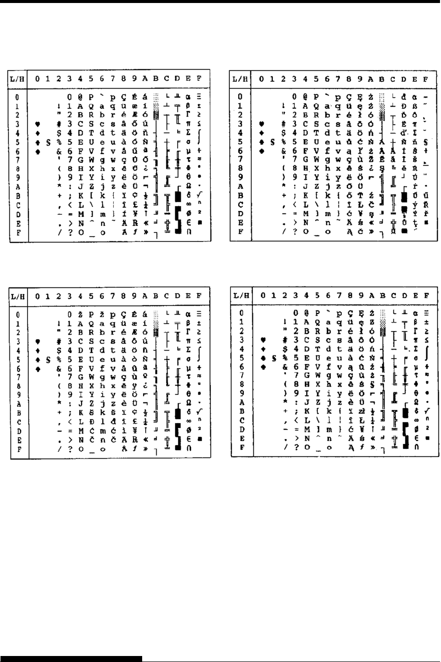
CHARACTER SETS
User's Manual E-7
HUNGARY/HUNG-T (Hungarian) POLISH/POLS
H
-T (Polish)
SLOV/SLOV-T (Slovenian) MAZOWIA/MAZO
W
-T (Mazowian)
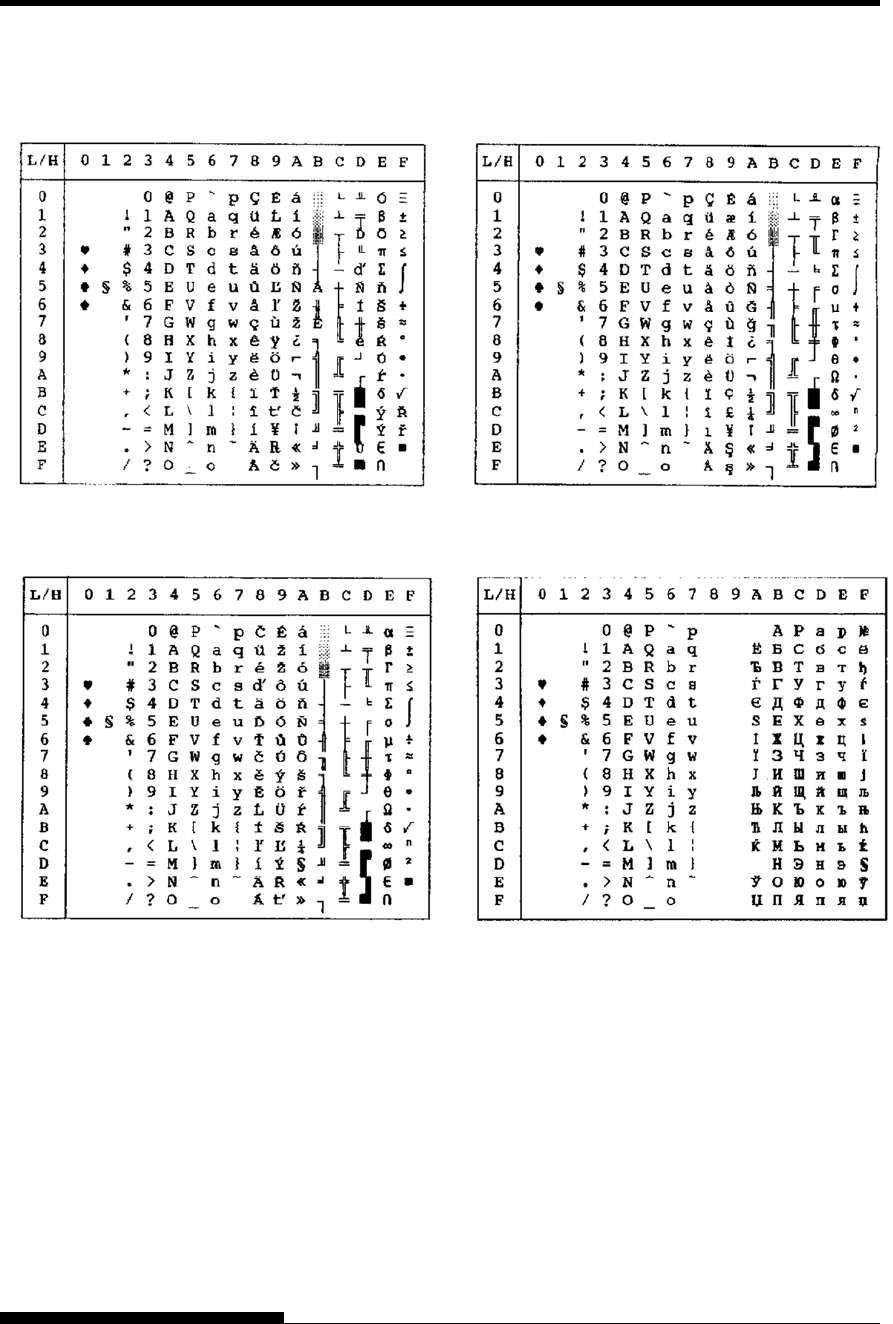
CHARACTER SETS
E-8 User's Manual
LATIN2/LATN2-T (Latin2) TURKY/TURKY-T (Turkish)
KAMENIC/KAMEN-T (Kamenicky) CYRILIC (Cyrillic)
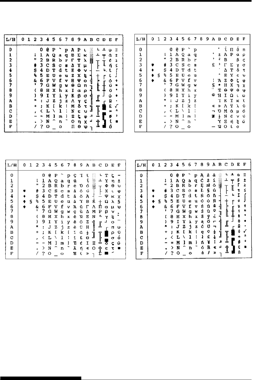
CHARACTER SETS
User's Manual E-9
IBM437 (IBM 437) ELOT928 (ELOT 928)
IBM851 (IBM 851) PG-DHN (Code Page DHN)
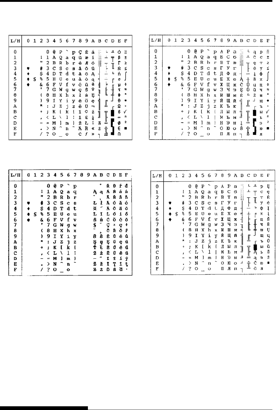
CHARACTER SETS
E-10 User's Manual
LATIN-P (Latin Polish) LITHUA1 (Lithuanian 1)
ISO-LTN (ISO Latin) LITHUA2 (Lithuanian 2)
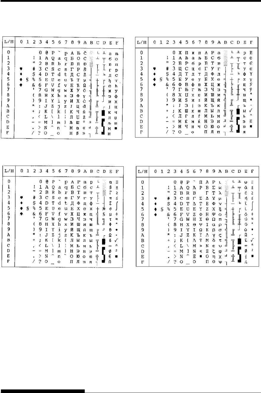
CHARACTER SETS
User's Manual E-11
MACEDON (Macedonian) PG-MAC
MI
K
ELOT 927
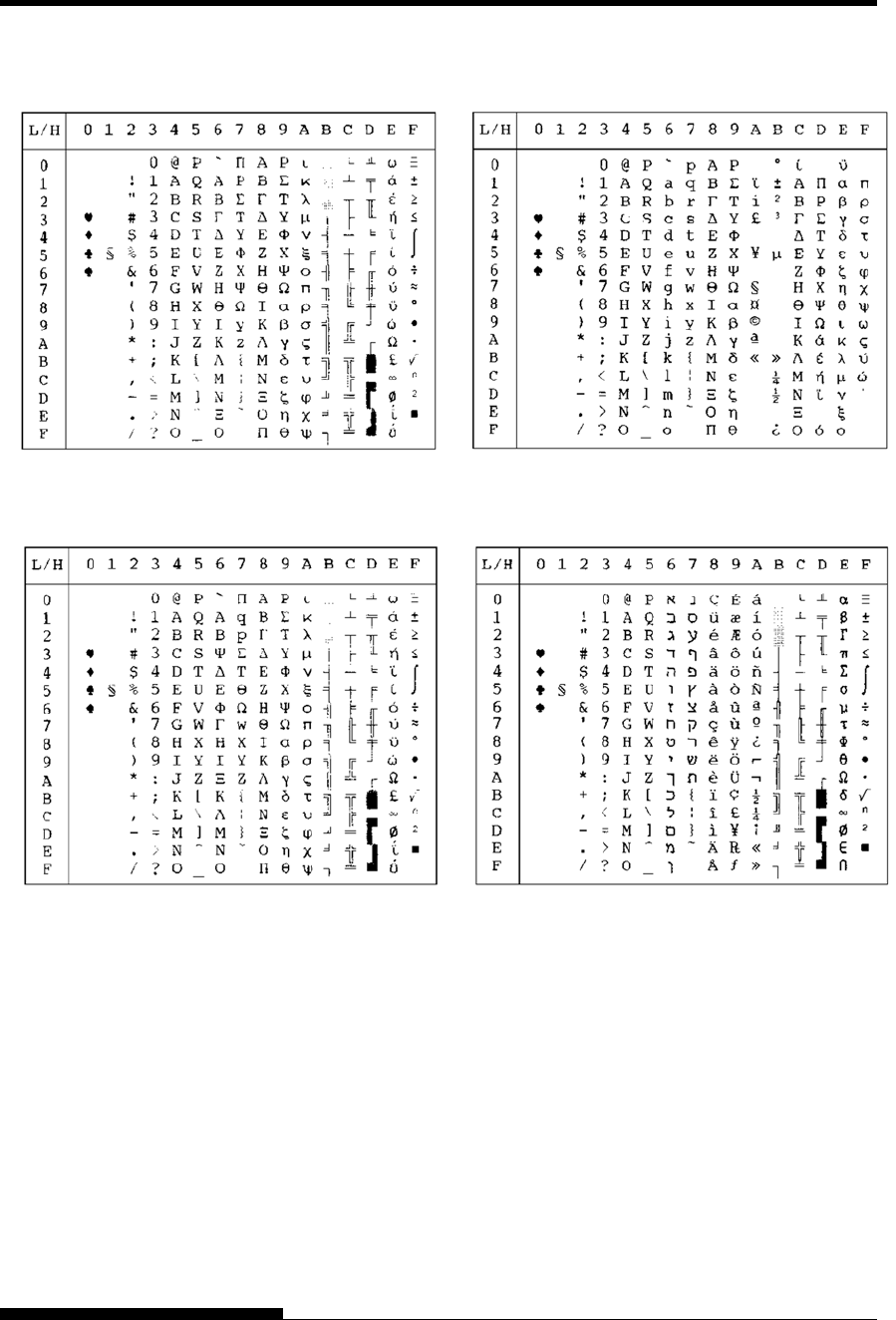
CHARACTER SETS
E-12 User's Manual
ABG DEC G
R
ABY HB
R
-OLD
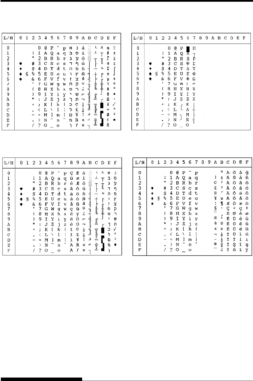
CHARACTER SETS
User's Manual E-13
PAGE 862 (Code Page 862) GREEK 11
HB
R
-DEC ISO-TUK
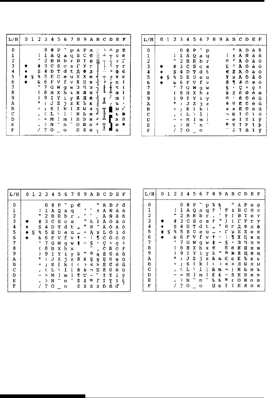
CHARACTER SETS
E-14 User's Manual
RUSCII LATIN-9
WCP1250 (Windows
–
1250)
WCP1251 (Windows
–
1251)
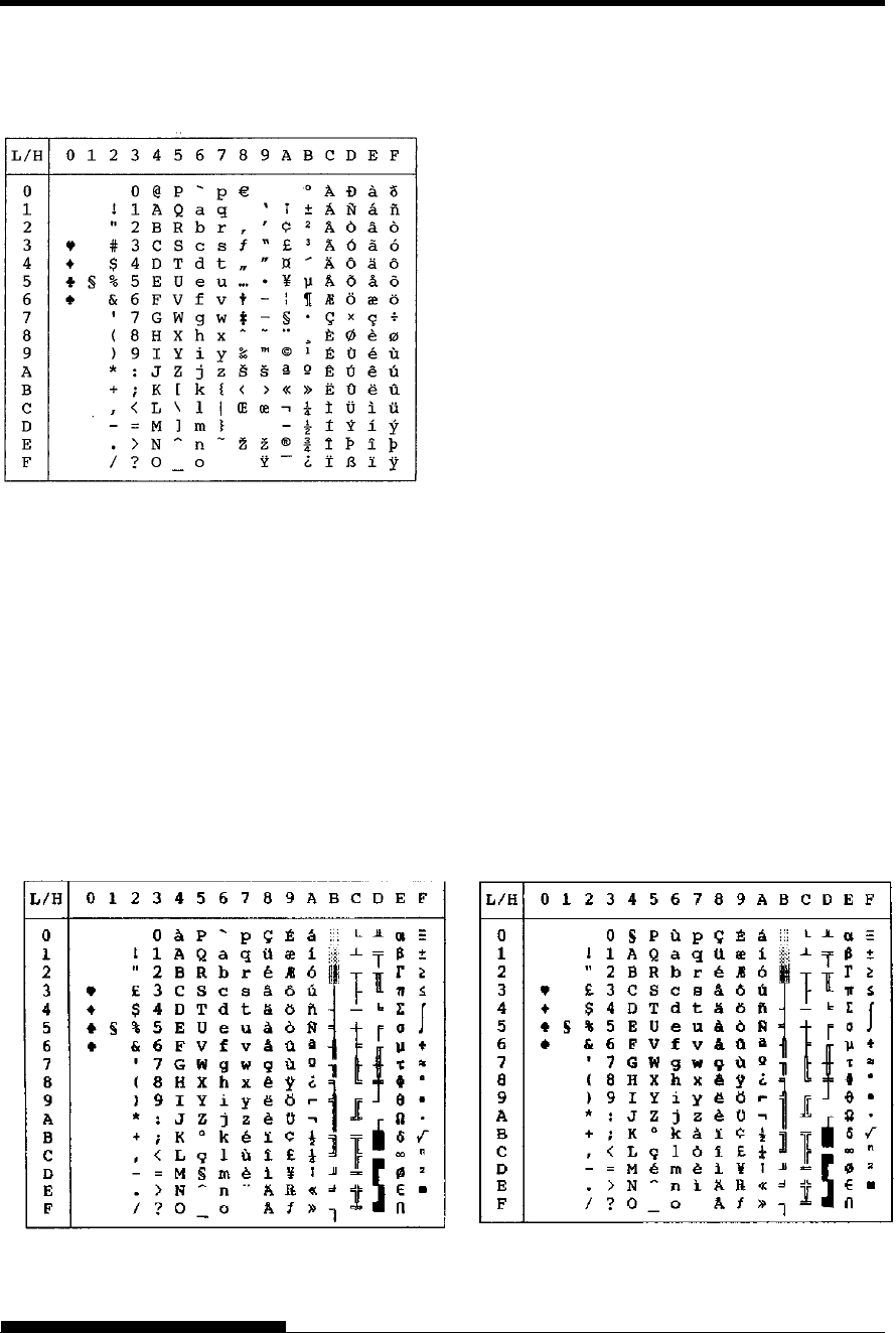
CHARACTER SETS
User's Manual E-15
The following character sets differ from those of Code Page 437 (USA),
available in the DPL24C PLUS command set and the IBM Proprinter
XL24E emulation.
NATIONAL
CHARACTER SETS
(DPL24C PLUS AND
IBM XL24E
EMULATION)
FRENCH (French) ITALIAN (Italian)
WCP1252 (Windows
–
1252)
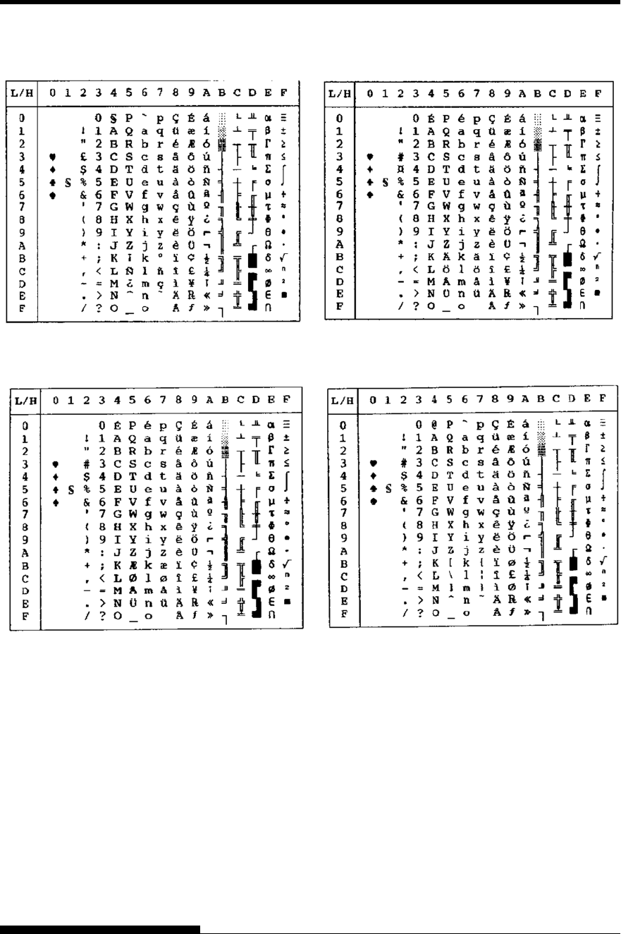
CHARACTER SETS
E-16 User's Manual
SPANISH (Spanish) FINNISH (Finnish)
DANISH1/NORWEGN (Danish1/Norwegian) DANISH2 (Danish2)
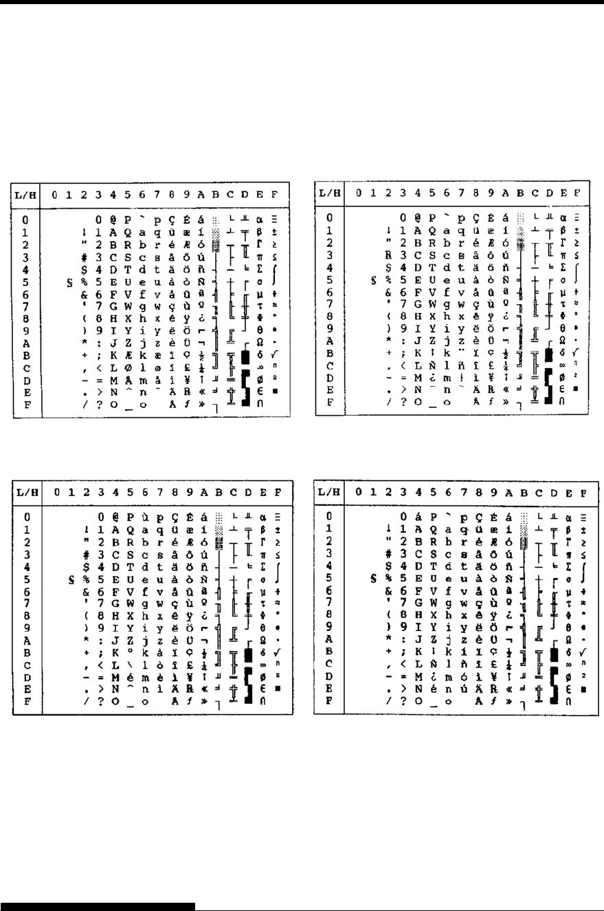
CHARACTER SETS
User's Manual E-17
The following character sets differ from the graphics character sets
available in the Epson ESC/P2 emulation.
NATIONAL
CHARACTER SETS
(ESC/P2
EMULATION)
DANISH1 (Danish1) SPANSH1 (Spanish1)
ITALIAN (Italian) SPANSH2 (Spanish2)
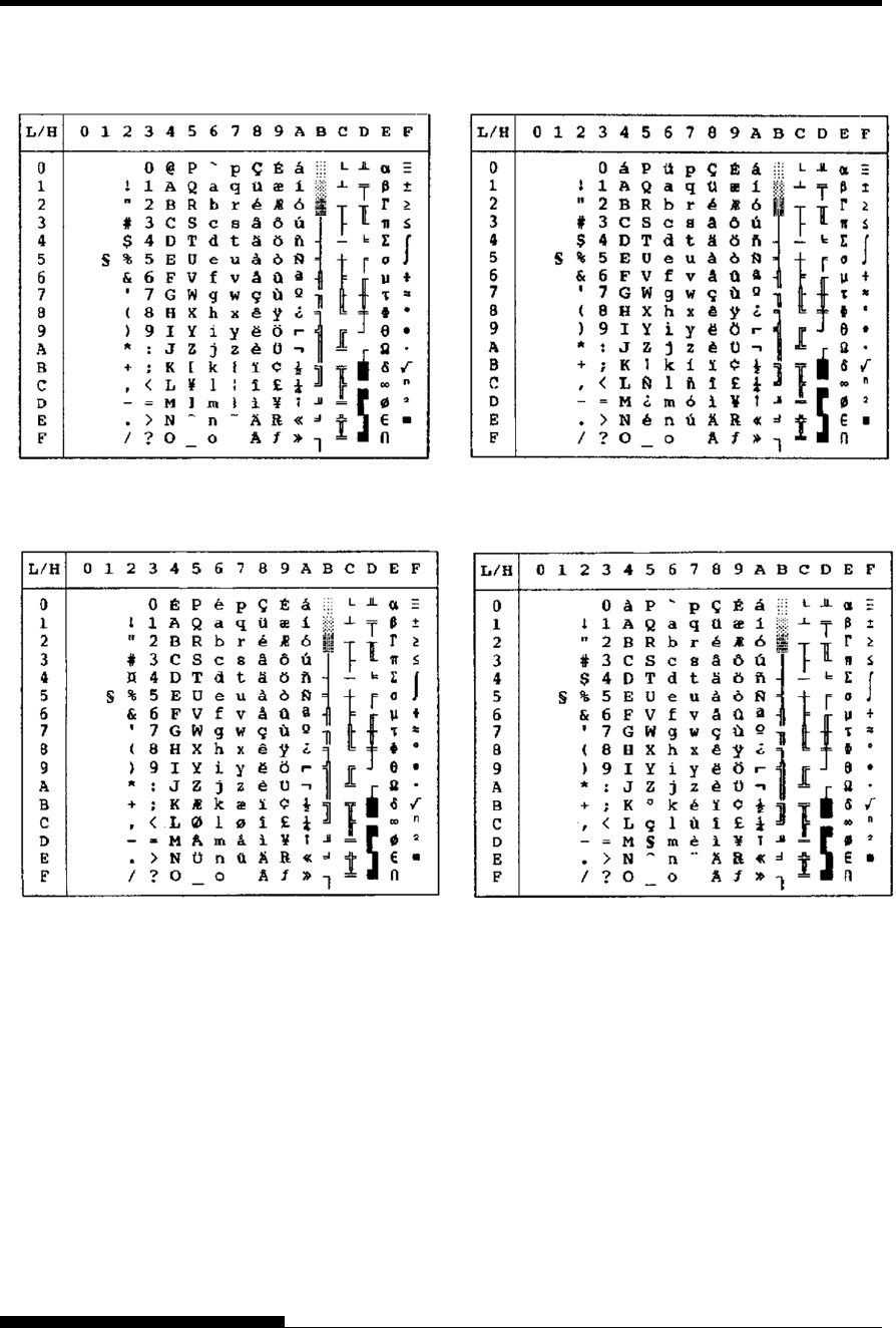
CHARACTER SETS
E-18 User's Manual
JAPAN (Japanese) LATIN A (Latin American)
N
ORWEGN (Norwegian) FRENC
H
(French)
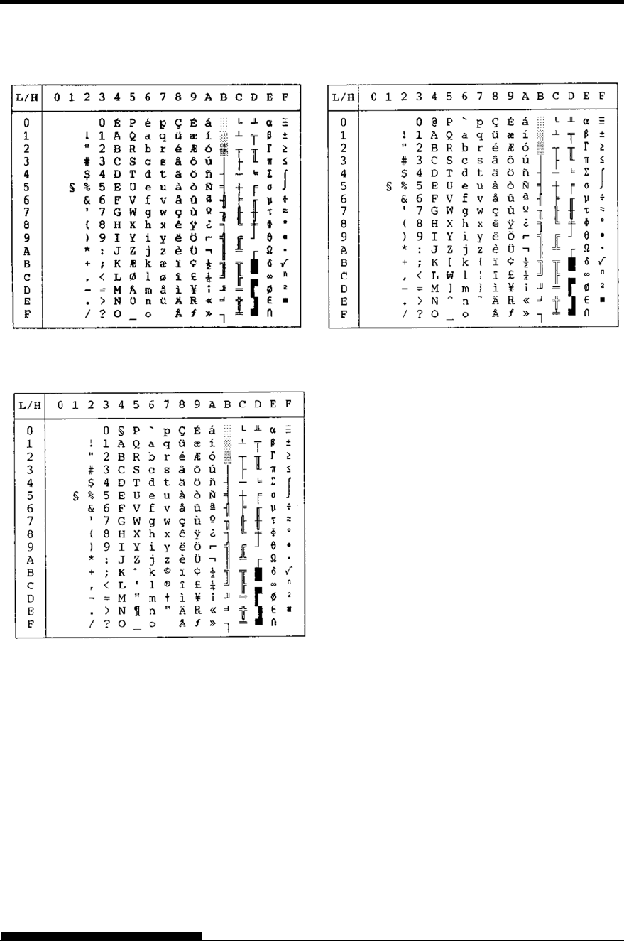
CHARACTER SETS
User's Manual E-19
DANISH2 (Danish2) KOREA
LEGAL
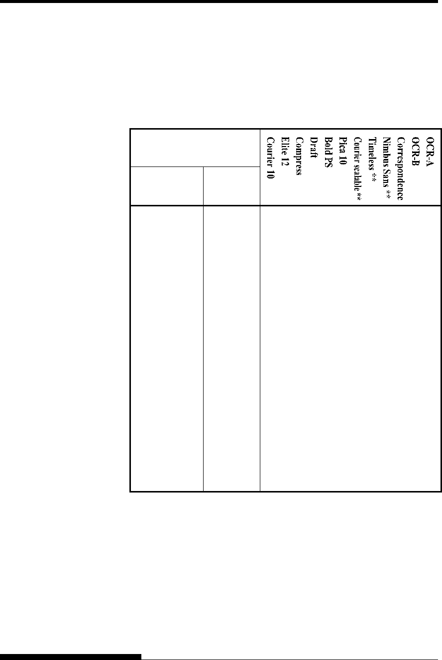
CHARACTER SETS
E-20 User's Manual
In all emulations, this printer supports 52 national character sets for
characters and symbols specific to different languages. Some national
character sets, however, do not have some characters and symbols and
may not be usable, depending on resident fonts. The following tables
show which of the resident fonts are supported for each national
character set:
Resident font
National
character set Name in
setup menu
USA * USA
United Kingdom UK
German GERMAN
Swedish SWEDISH
ISO 8859-1 ISO8859
ECMA94 ECMA94
Code Page 437* PAGE437
Code Page 850 PAGE850
Code Page 852 PAGE852
Code two-pass PAGE852-T
Code Page 855 PAGE855
Code Page 860 PAGE860
Code Page 863 PAGE863
Code Page 865 PAGE865
Code Page 866 PAGE866
(Continued on the next page)
* USA is the same as Code Page 437.
** Upright, italic, and bold available
: Supported
NATIONAL
CHARACTER SETS
AND SUPPORTED
RESIDENT FONTS
(ALL EMULATIONS)
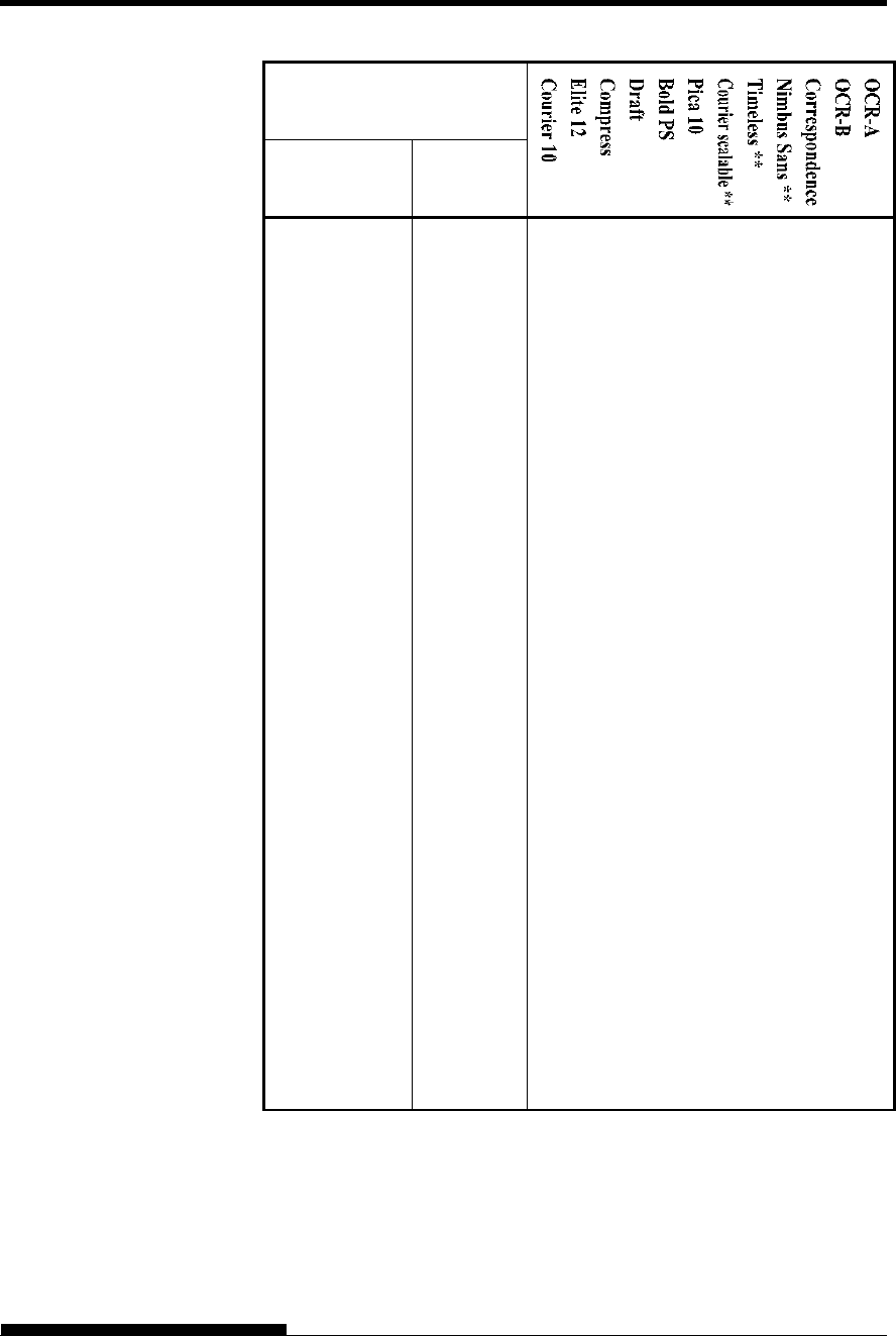
CHARACTER SETS
User's Manual E-21
Resident font
National
character set Name in
setup menu
Hungarian HUNGARY
Hungarian two-
pass
HUNG-T
Slovenian SLOV
Slovenian two-
pass
SLOV-T
Polish POLISH
Polish two-pass POLISH-T
Mazowian MAZOWIA
Mazowian two-
pass
MAZOW-
T
Latin 2 LATIN2
Latin 2 two-pass LATIN2-T
Kamenicky KAMENIC
Kamenicky two-
pass
KAMEN-T
Turkish TURKY
Turkish two-pass TURKY-T
Cyrillic CYRILIC
IBM 437 IBM437
IBM 851 IBM851
ELOT 928 ELOT928
Code Page DHN PG-DHN
Latin Polish LATIN-P
ISO Latin ISO-LTN
(Continued on the next page)
** Upright, italic, and bold available
: Supported
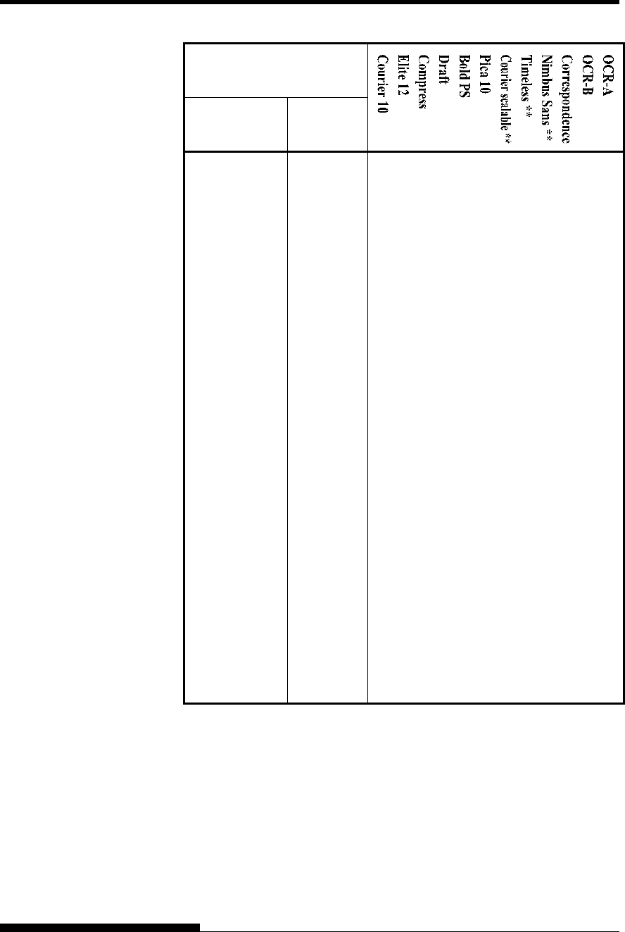
CHARACTER SETS
E-22 User's Manual
Resident font
National
character set Name in
setup menu
Lithuanian 1 LITHUA1
Lithuanian 2 LITHUA2
MIK MIK
Macedonian MACEDON
ABG ABG
ABY ABY
DEC Greek DEC GR
ELOT 927 ELOT 927
GREEK 11 GREEK 11
Code Page 862 PG 862
Hebrew DEC HBR-DEC
Hebrew Old HBR-OLD
Code Page MAC PG-MAC
ISO Turkish ISO-TUK
RUSCII RUSCII
ISO8859-15 LATIN-9
Windows Code
Page 1250
WCP1250
Windows Code
Page 1251
WCP1251
Windows Code
Page 1252
WCP1252
** Upright, italic, and bold available
: Supported
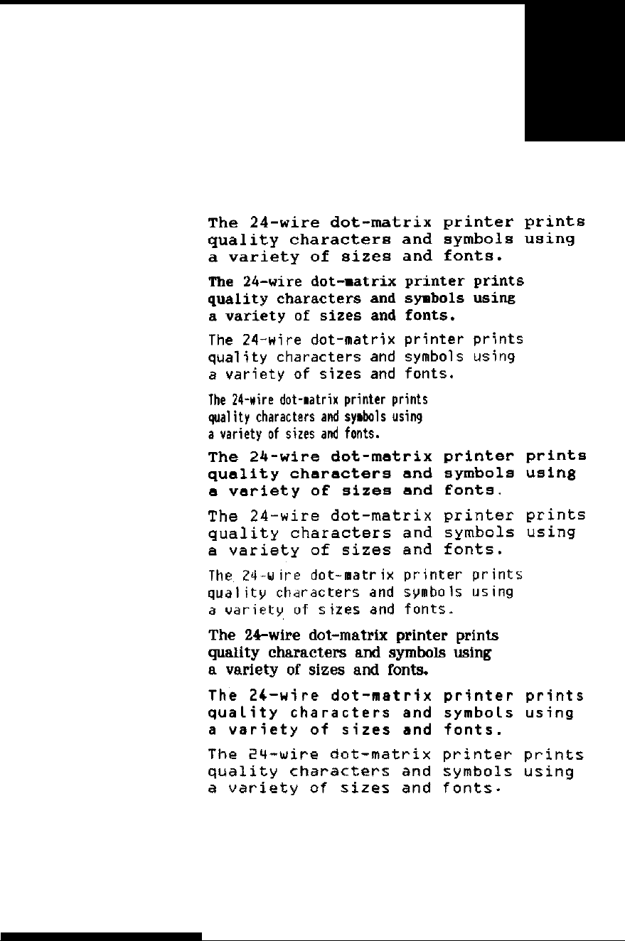
User's Manual F-1
F
APPENDIX F RESIDENT FONTS
RESIDENT FONTS
This appendix provides print samples of
the printer's nineteen resident fonts.
COURIER 10
PRESTIGE ELITE 12
DRAFT 12
COMPRESSED
PICA 10
CORRESPONDENCE 10
HIGH-SPEED DRAFT 12
BOLDFACE PS
OCR-B 10
OCR-A 10
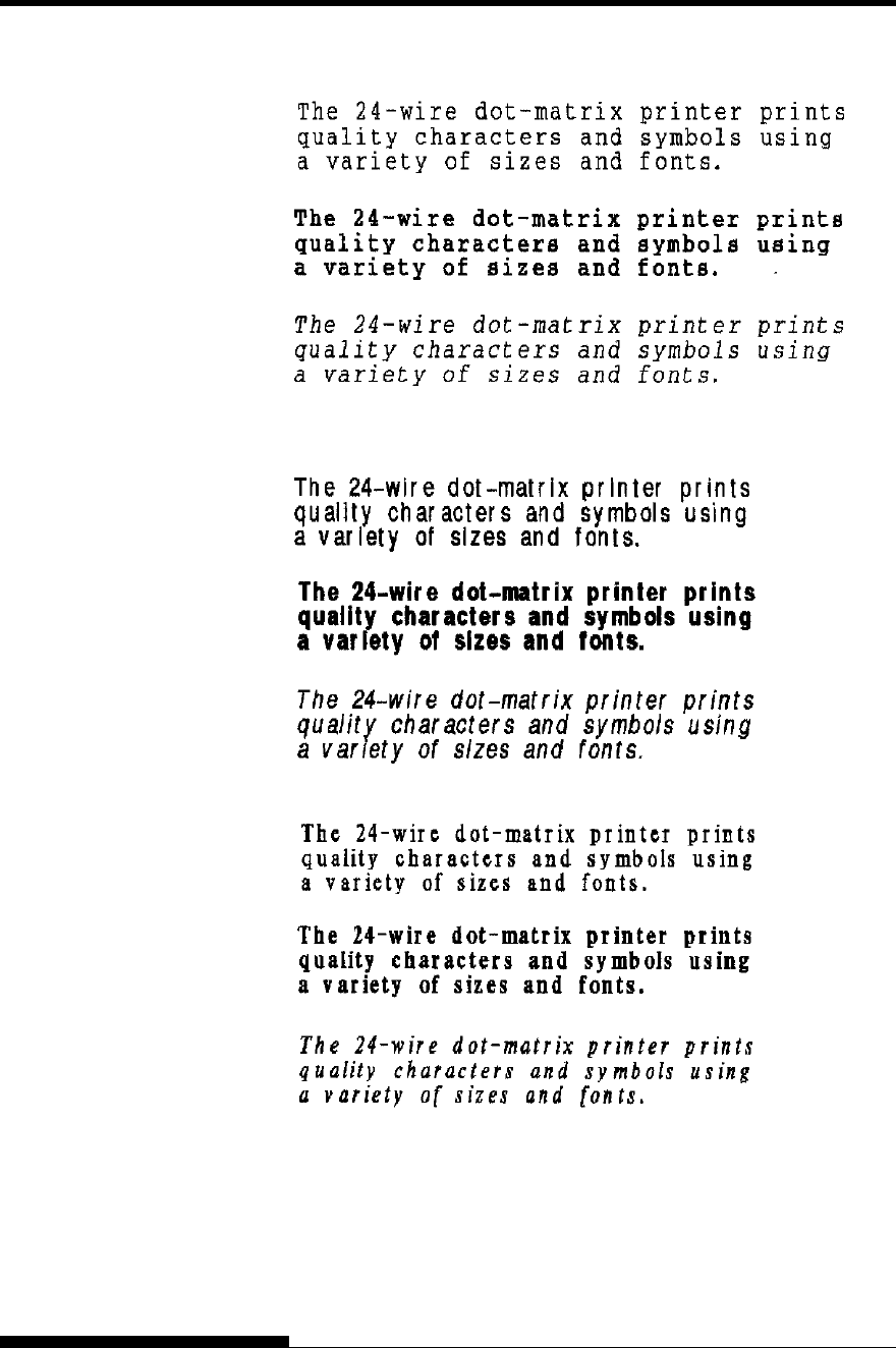
RESIDENT FONTS
F-2 User's Manual
COURIER (SCALABLE)
Normal
Bold
Italic
Normal
Bold
Italic
Normal
Bold
Italic
NIMBUS SANS
(SCALABLE)
TIMELESS (SCALABLE)

User's Manual IN-1
INDEX
INDEX
A
Adjustments
left margin ..................... 3-13, 3-16, 3-19, 5-21
left print start position ............................... 5-37
top-of-form .................... 3-24, 5-21, 5-34, 5-35
paper thickness................................... 3-9, 3-10
AMOUNT ...................................................... 5-51
ATTRIB ......................................................... 5-19
B
Bidirectional printing ............................. 5-30, 5-59
Boldface ...........................................1-1, 4-10, F-1
BUFFER ............................... QR-3, 4-1, 5-30, B-1
BUZZER ........................................................ 5-30
C
Cables
LAN ................................... 1-3, 2-22, 8-1, A-1
parallel interface .............................. 2-21, 5-31
serial interface ......................... 2-21, 5-14, 5-31
USB ....................................... 2-22, 5-31, D-11
Centronics ..................................... 2-21, 5-31, D-1
Character .............................. 5-18, 5-22, 5-25, E-1
Cleaning .......................................................... 6-1
Continuous forms
loading ............................................. 3-12, 3-15
placement ................................................. 3-11
tearing off ................................................. 3-17
unloading .................................................. 3-17
Control panel ......................... QR-1, 2-15, 3-2, 4-7
Cut sheet feeder
installing ...................................... 3-7, 8-1, A-1
loadin g ...................................................... 3-21
D
Default ........................................... 5-4, 5-12, 5-53
Demo pattern .................................................. 2-20
Diagnostic functions ............................. 5-55, 7-11
Download ........................................ B-1, B-4, C-8
DPL24C PLUS .............................................. 5-16
DRAFT .................................................. 5-17, B-2
E
Eject .................................................... QR-2, 3-23
Emulation ............................................. 2-23, 5-16
Envelope ....................................................... 3-26
Epson ESC/P2 ...................................... 5-16, 5-65
F
Feeding paper
form feed ................................ QR-2, 3-3, 3-24
line feed .................................. QR-2, 3-3, 3-24
Font ........................................................ 4-9, 5-16
Function ................................................. 5-4, 5-12
H
HEX-DUMP .......................... 5-4, 5-12, 5-55, 7-11
I
IBM Proprinter XL24E ................. 2-23, 5-16, 5-65
Interface ........................................ 2-22, 5-31, D-1
L
Label ............................................................. 3-26
LAN interface .............................. 2-23, 5-31, D-12
LF/FF .................................................... QR-2, 3-3
Line feed ...............................QR-2, 3-3, 3-24, B-5
Line spacing ................................. 5-19, 5-38, B-4
LIST ................................................ 5-4, 5-9, 5-12
LOAD ................................................... QR-2, 3-3
Loading ............................... 3-12, 3-15, 3-19, 3-21
Lubrication ...................................................... 6-1

INDEX
IN-2 User's Manual
M
Maintenan ce..................................................... 6-1
Margin ........................................................... 5-34
Menu ............................ QR-3, 2-25, 4-8, 5-4, 5-12
Multipart paper ............................................... B-8
N
Number of copies ............................ 3-9, 3-10, B-3
O
ONLINE ....................................... QR-2, 3-3, 5-43
Order number .................................................. A-1
P
Page ............................................................... 2-26
PAPER OUT............................. 4-3, 5-29, 7-7, 7-9
Paper path .......................................QR-2, 3-3, 3-5
Power ................................... QR-2, 2-17, 7-7, B-1
Print area ........................................................ B-6
Print head ......................................................... 6-8
Printer Driver ................................................. 2-28
Q
QUALITY .............................................. 5-17, 7-1
Quick Reference........................................... QR-1
R
Removing printed pages ................................... 4-5
Replacing the ribbon ........................................ 6-3
Resume printing .................................... QR-3, 4-3
Ribbon cartridge................................ 2-7, 6-3, A-1
Ribbon subcassette .......................................... A-1
RS-232C ........................................................ 5-31
S
Self-test ................................. 2-18, 5-4, 5-12, 5-55
Serial interface .............................. 2-21, 2-28, D-7
Setup mode ..................................................... 5-1
Single sheet
loadin g ...................................................... 3-19
Single sheets .............................................. B-6
ejecting ..................................................... 3-23
Soft ware .......................................................... 4-6
Specifications .................................................. B-1
Supplies .......................................................... A-1
T
TEAR OFF................................... QR-2, 3-3, 3-17
Testing printer
offline ....................................................... 2-18
online........................................................ 2-26
Top margin..................................................... 5-21
U
Unidirectional printing............................ 5-30, B-2
Un packin g ....................................................... 2-2
USB interface .............................. 2-22, 5-31, D-11
V
V-ALMNT function ....................................... 5-59
Vertical character displacement ...................... 5-59
W
WIDTH .......................................... 5-26, B-1, B-2
Please send your comments on this manual or on Fujitsu products to the
following addresses:
North American Contact:
FUJITSU CANADA INC.
6975 Creditview Road, Unit 1
Mississauga, ON, Canada
L5N 8E9
Phone: +1-905-286-9666
Fax: +1-905-286-5997
European, Middle East, African
Contact:
Fujitsu Technology Solutions GmbH
Mies-van-der-Rohe-Strasse 8
80807 Munich, Germany
Phone: +49-89-62060-0
Internet: www.fujitsu.com/fts/
Australian Contact:
FUJITSU AUSTRALIA LTD.
Fujitsu House 2 Julius Avenue
North Ryde N.S.W. 2113
Australia
Phone: +61-2-9776-4555
Fax: +61-2-9776-4556
Asian Contact:
FUJITSU HONG KONG LTD.
10/F., Lincoln House, 979 King's Road
Taikoo Place, Island East, Hong Kong
Phone: +852-2827-5780
Fax: +852-2827-4724
FUJITSU TAIWAN LTD.
19F, No.39, Section 1, Chung hwa Road Taipei, Taiwan
Phone: +886-2-2311-2255
Fax: +886-2-2311-2277
FUJITSU SYSTEMS BUSINESS (THAILAND) LTD.
22-23 Fl., Exchange Tower, 388 Sukhumvit Rd.
Klongtoey, Bangkok, Thailand 10110
Phone: +66-2-302-1500
Fax: +66-2-302-1555
FUJITSU ASIA PTE. LTD.
20, Science Park Road, #03-37 TeleTech Park
Singapore Science Park II, Singapore 117674
Phone: +65-6512-7555
Fax : +65 6512-7502
FUJITSU PHILIPPINES, INC.
2nd Floor, United Life Building, A. Arnaiz Avenue
Legaspi Village 1229, Makati City
Metro Manila, Philippines
Phone: +63-2-812-4001
Fax: +63-2-817-7576
FUJITSU (MALAYSIA) SDN. BHD.
Level 1 & 2, No.3505 Jalan Technokrat 5
Cyberjaya, Selangor Darul Ehsan, Malaysia 63000
Tel: +60-3-8318-3700
Fax: +60-3-8318-8700
PT FUJITSU INDONESIA OFFICES
Wisma Kyoei Prince 10th Floor
Jl. Jend. Sudirman Kav 3-4, Jakarta Indonesia 10220
Phone: +62-21-570-9330
Fax: +62-21-573-5150
FUJITSU VIETNAM LIMITED
Unit 01-03, 17th Floor, Keangnam Hanoi Landmark Tower,
Lot E6, Cau Giay New Urban Area, Me Tri Ward, Tu Liem
District, Hanoi, Vietnam
Phonel:+84-4-22203113
Fax: +84-4-22203114
Manufacturer contact:
FUJITSU ISOTEC LIMITED
Printer Business Division
135, Higashinozaki, Hobara-machi, Date-shi, Fukushima
960-0695, JAPAN
Phone: +81-24-574-2236,
Fax: +81-24-574-2382
URL http://jp.fujitsu.com/group/fit/en/
Contact Email fit-gsm@cs.jp.fujitsu.com
FUJITSU OFFICES

KA02087-Y890-01EN