Fujitsu Technology Solutions MOB75001 User Manual A26391 K84 Z100 1 7619
Fujitsu Technology Solutions GmbH A26391 K84 Z100 1 7619
UserManual.wiki
>
Fujitsu Technology Solutions
>
MOB75001 User Manual
Mobile 750 Operating Manual August 1998 Edition
Navigation menu
Upload a User Manual
Namespaces
Wiki Guide
HTML
PDF
Info
Views
User Manual
Discussion / Help
Navigation
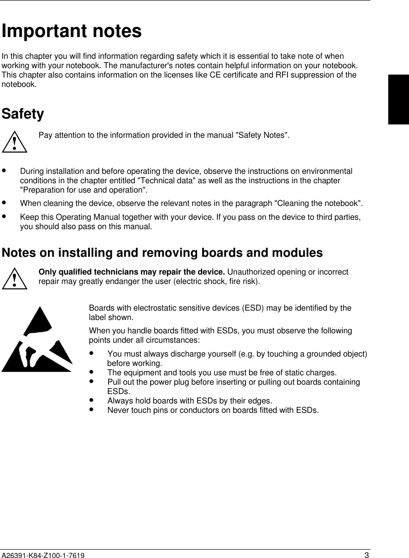


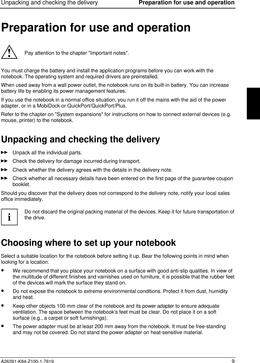
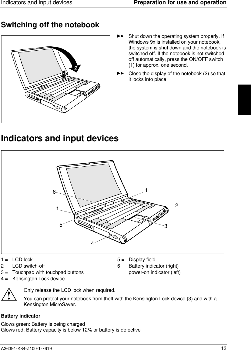
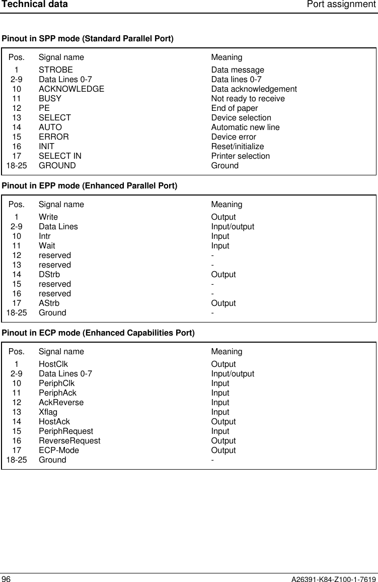
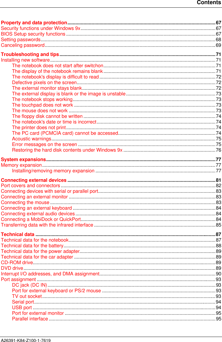
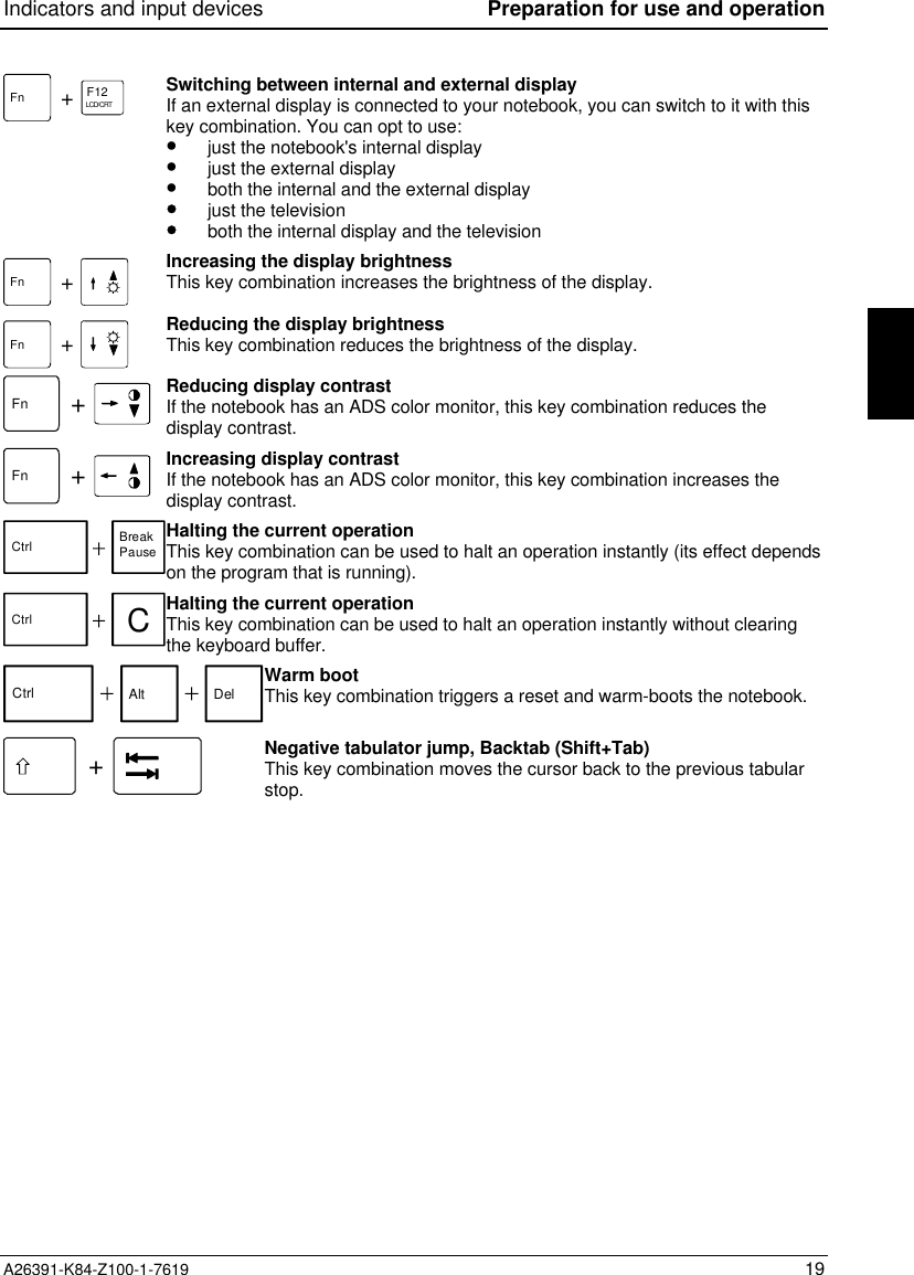
![Indicators and input devices Preparation for use and operationA26391-K84-Z100-1-7619 15Touchpad and Touchpad Keys!Make sure that the touchpad does not come into contact with dirt, liquids or grease.Do not touch the touchpad if your fingers are dirty.Do not rest heavy objects (e.g., books) on the touchpad or the touchpad buttons.The touchpad enables you to move the mouse pointer on the screen. If, for example, you move onefinger to the left over the touchpad, the mouse pointer also moves to the left.A brief tap with the finger on the touchpad has the same effect as clicking with the left mouse button. Abrief "double-tap" with the finger on the touchpad has the same effect as double-clicking with the leftmouse button.The left and right touchpad buttons have the same functions as the left and right mouse buttons.iIf you attach and install an external mouse, the touchpad and its buttons are disabled. If youattach an external serial mouse, you must select the Disabled option for thePS/2 Pointing Device field in the Main Setup. This also releases interrupt 12, so that you canuse it for other applications.KeyboardEscF1F2F3F4 F5 F6F7F8 F9F10F11F12ELCD/CRTCD slow LCD Off Suspend CPU slow Info LCD TV on/offCtrl|PgDnFn`!1@2#3$4%5^67 890-QW RT Y UI OP{ }AZSXDCFVGBHNJMK<L>?:"&7*8(9)/_+=]456*End123-0,. /+PauseBreakPrtScrnSysRqPad NumAlt Alt Gr Ins DelHome\\PgUp[,;.LockScrollLockCaps Lock~StandbyThe following description of keys and key combinations refers to Windows 9x Additional functionssupported by the keys are described in the relevant manuals supplied with your application programs.](https://usermanual.wiki/Fujitsu-Technology-Solutions/MOB75001/User-Guide-26802-Page-15.png)
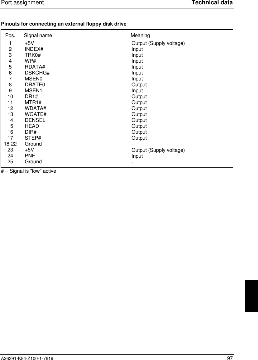
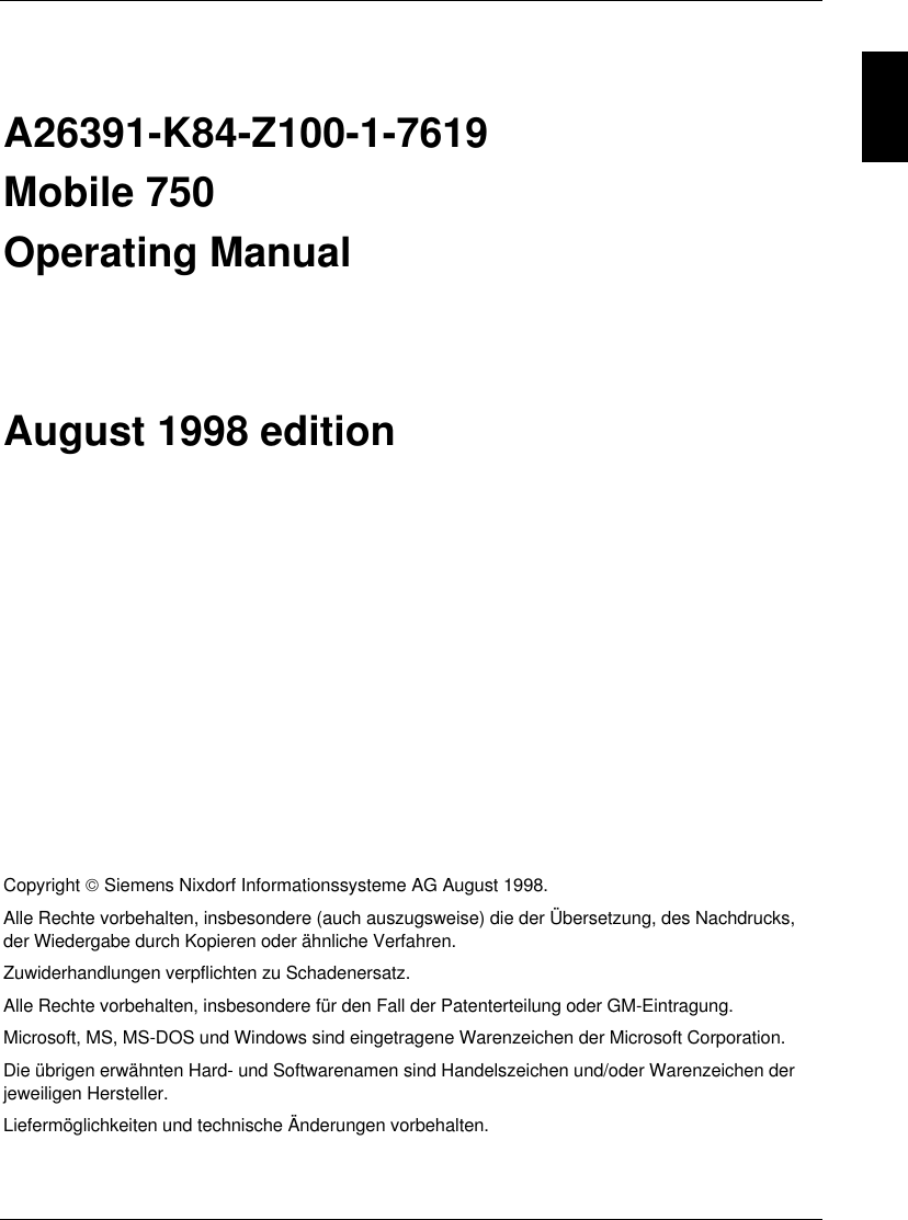
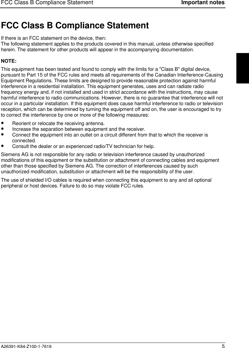
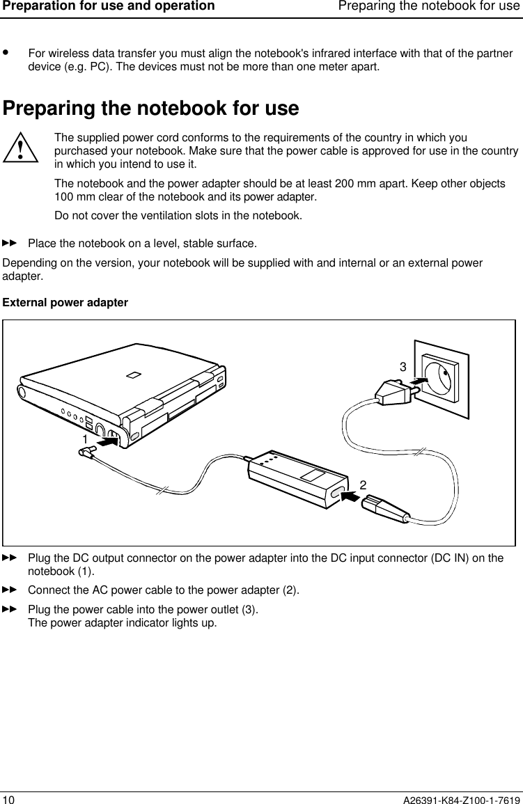
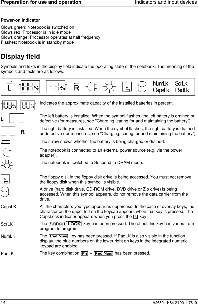
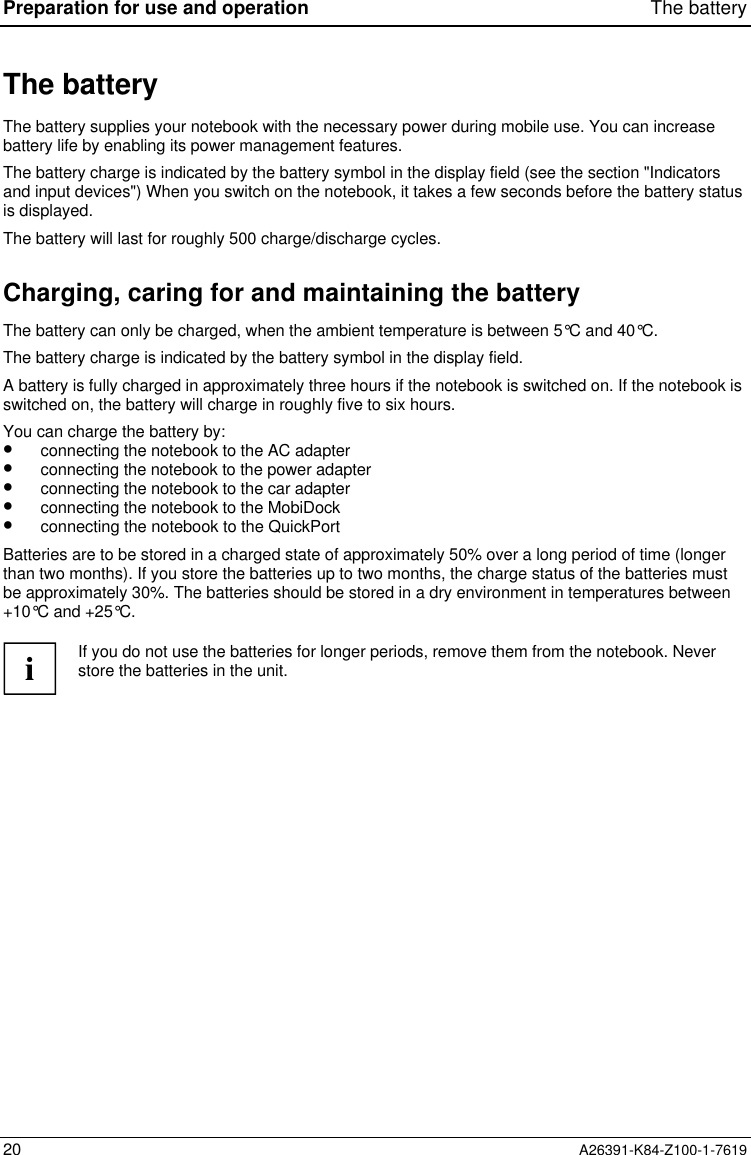
![Indicators and input devices Preparation for use and operationA26391-K84-Z100-1-7619 17Cursor keysThe cursor keys move the cursor in the direction of the arrow, i.e., up, down, left, orright.Pad Num Pad Num keyWhen the numeric keypad is enabled (PadLK is visible in the display field), the key causes this set of keys to produce numbers (NumLK appears in thedisplay field). Pressing them produces the blue characters shown on the bottom righton the keycaps.PauseBreak Pause keyThe key temporarily suspends display output. Output will resume when pressany other key.Start keyinvokes the START menu of Windows.Menu keyThe Menu key invokes the menu for the marked item (Windows).EEuro keyThe Euro-key produces the Euro character (Windows 98 and Windows NT5.0).Numeric keypad7 890UI OPJMK;L:_Ö/{([)]=}µ, . -789 /456*123-0+,121 = Characters enabled when neither PadLK, nor NumLK are visible in the display field.2 = Characters enabled when PadLK and NumLK are visible in the display field.The key enables and disables the integrated numeric keypad. If the numeric keypad isenabled (NumLK is shown in the display field) and you hold the key down, you can output thecharacters printed in blue at the right bottom of the keys.When the numeric keypad is enabled (NumLK is visible in the display field), pressing the keycombination + enables and disables the numeric entry in the integrated numerickeypad. If numeric entry is enabled (NumLK and PadLK are shown in the display field), the bluecharacters at the bottom right of the keys are effective.](https://usermanual.wiki/Fujitsu-Technology-Solutions/MOB75001/User-Guide-26802-Page-17.png)
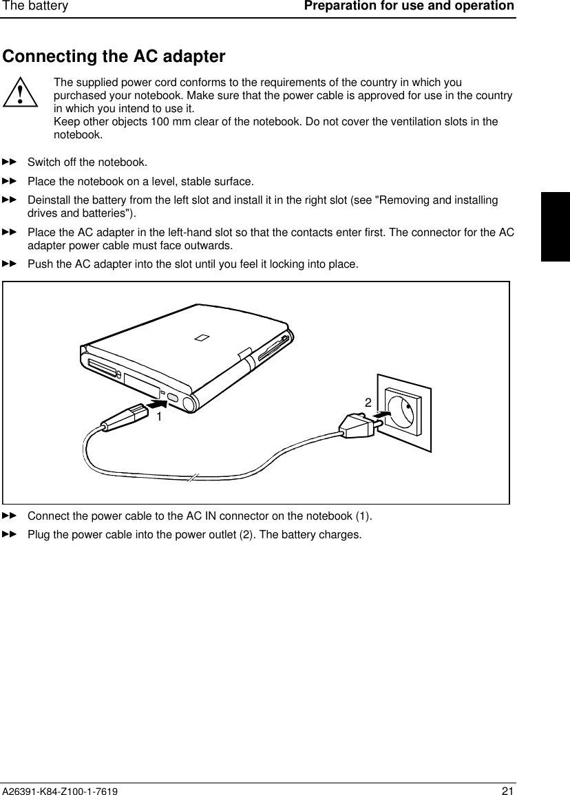
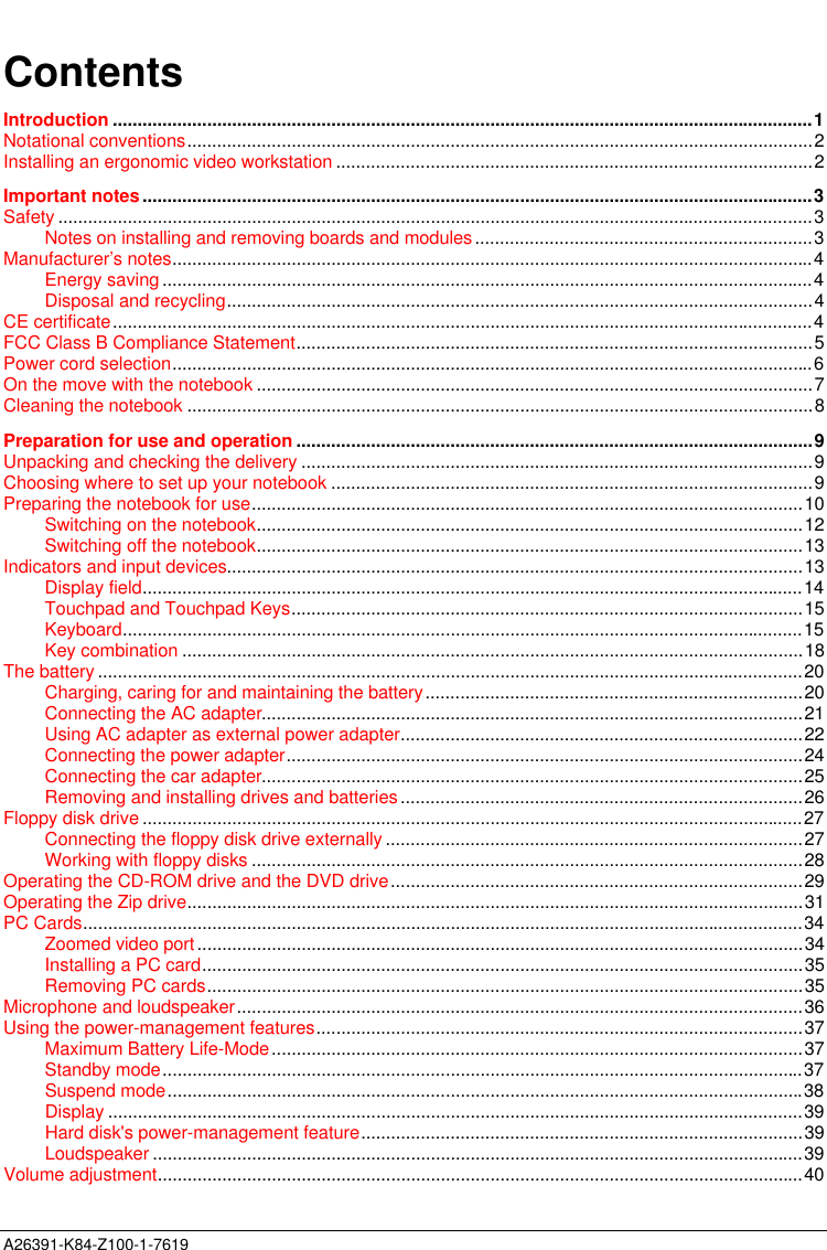
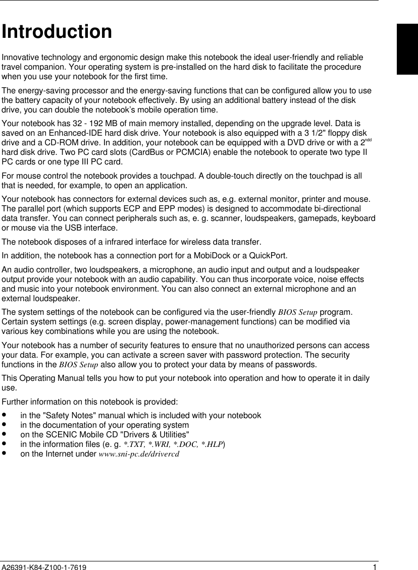
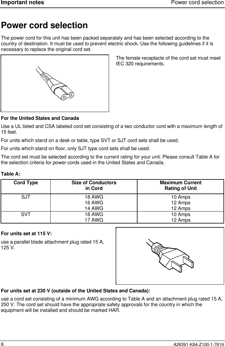
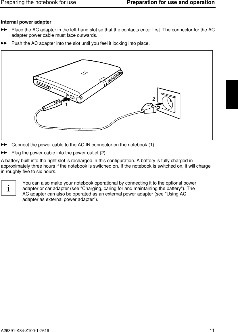
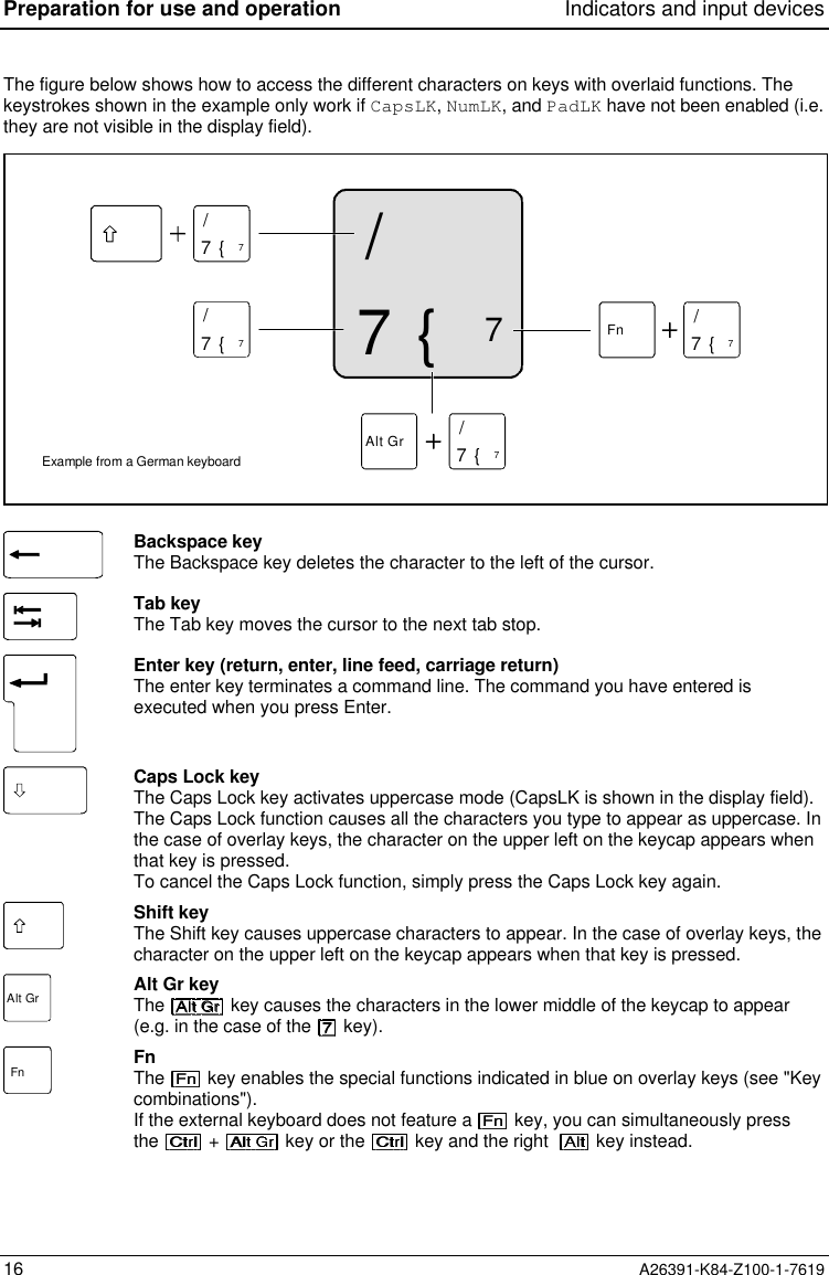
![BIOS Setup Operating BIOS Setup42 A26391-K84-Z100-1-7619The Main menu is displayed on the screen. Phoenix BIOS Setup Main Advanced Security Power Docking Boot Exit System Time: [08:00:00] System Date: [12/12/1997] Diskette A: [1.44M, 3 ] IDE Adapter 0 Master (C: 810 MB) IDE Adapter 1 Master [None] Display Device Selection: [LCD & CRT] TV Mode: [PAL] Boot Options System Memory: 640 KB Extended Memory: 15 MB Item Specific Help—————————————————————— F1 Help ↑↓ Select Item Space Change Values F9 Setup Defaults ESC Exit ← → Select Menu Enter Select Sub-Menu F10 Previous ValuesExample for Main menuOperating BIOS SetupUse the cursor key or to select the menu you wish to access to make changes.Press the Enter key. The menu is displayed on the screen.Use the cursor key or to select the field you wish to change.Press the Space key to change the value of an entry.You must enter characters in the Supervisor Password, User Password and Docking StationPassword fields.Repeat the last two steps described for all the fields you wish to change.Make a note of the changes you have made (here in this manual, for example).Using the function key, you can load the default settings for the Setup menu you are currentlyin.With the key all the values of the menu you are currently in are restored.](https://usermanual.wiki/Fujitsu-Technology-Solutions/MOB75001/User-Guide-26802-Page-42.png)
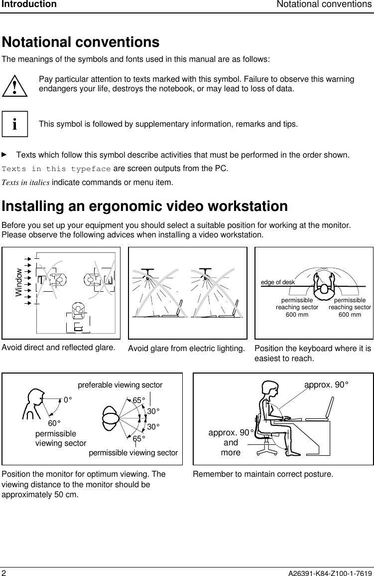
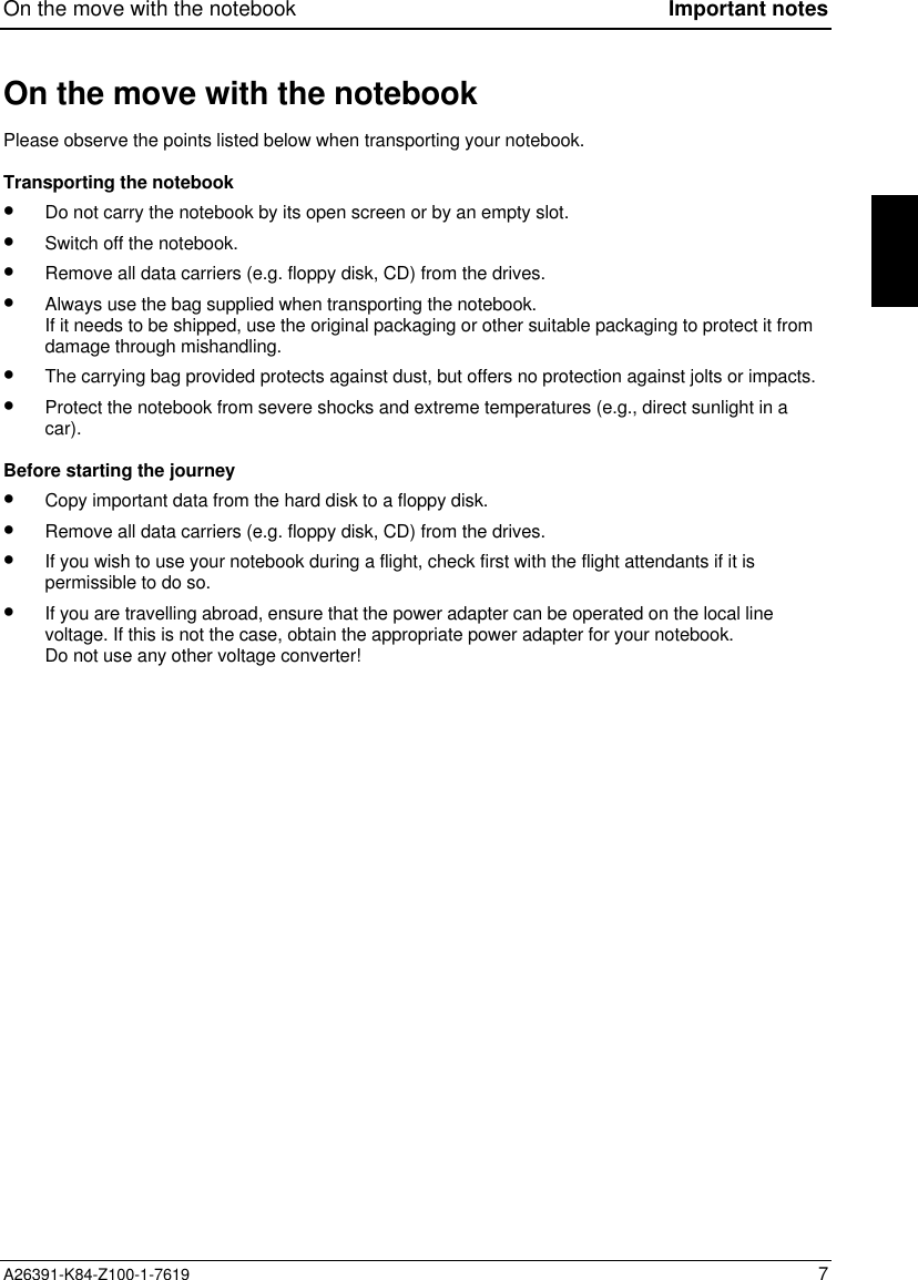
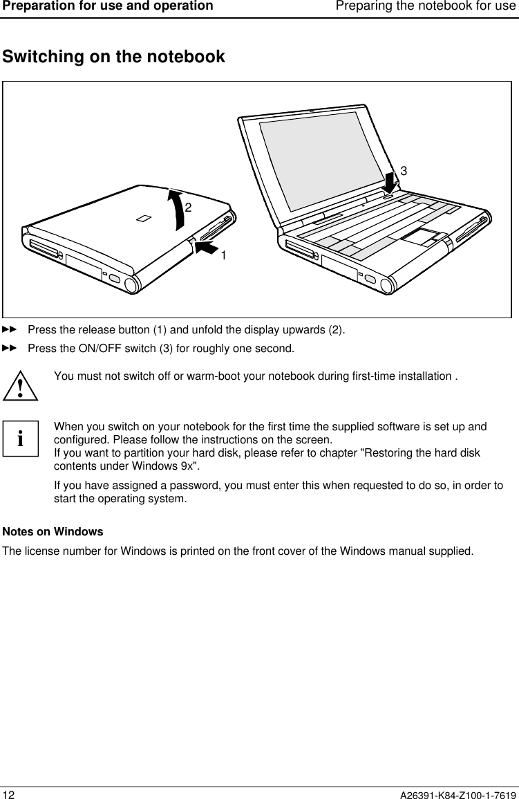
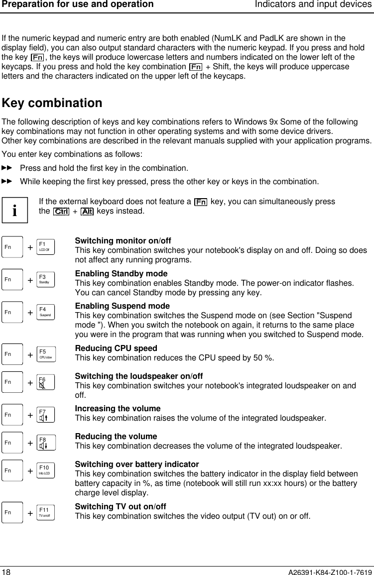
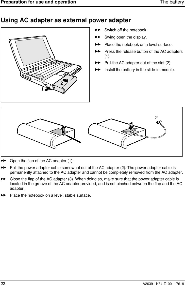
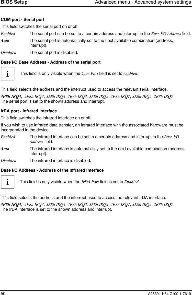
![Main menu - Making system settings BIOS SetupA26391-K84-Z100-1-7619 43Main menu - Making system settingsIn the Main menu you can set up the following:• time (in the field marked Time)• date (in the field marked Date)• hard disk settings (in the two fields marked IDE Adapter)• display device (in the field marked Display Device Selection)• Pointing elements (in the field marked PS/2 Pointing Device)• System startup options (in the field marked Boot Options) Phoenix BIOS Setup Main Advanced Security Power Docking Boot Exit System Time: [08:00:00] System Date: [08/14/1998] Diskette A: [1.44M, 3 ] IDE Adapter 0 Master (C: 810 MB) IDE Adapter 1 Master [None] Display Device Selection: [LCD & CRT] TV Mode: [PAL] Boot Options System Memory: 640 KB Extended Memory: 15 MB Item Specific Help—————————————————————— F1 Help ↑↓ Select Item Space Change Values F9 Setup Defaults ESC Exit ← → Select Menu Enter Select Sub-Menu F10 Previous ValuesExample for Main menuSystem Time/System DateSystem Time indicate the time of the device. If you change the time setting, enter the time in theformat HH:MM:SS (hours:minutes:seconds)System Date indicate the date of the device. If you change the date setting, enter the date in theformat MM.DD.YYYY (month/day/ year)Diskette A: - floppy disk driveThis field shows the type of the built-in floppy disk drive.360KB - 5 1/4", 720KB - 3 1/2", 1.2MB- 51/4", 1.44MB - 3 1/2", 2.88MB - 3 1/2"The entry depends on the floppy disk drive installed.Not Installed A floppy disk drive is not installed.](https://usermanual.wiki/Fujitsu-Technology-Solutions/MOB75001/User-Guide-26802-Page-43.png)
![BIOS Setup Main menu - Making system settings44 A26391-K84-Z100-1-7619IDE Adapter 0 Master/IDE Adapter 1 Master -hard disk driveThese two fields call the submenu to make corresponding settings of the IDE hard disk drives.iYou should change the default settings only if you are connecting an additional IDE drive(e.g. CD ROM drive)The following description of the setting options for IDE Adapter 0 Master also applies to IDE Adapter 0Slave, IDE Adapter 1 Master and IDE Adapter 1 Slave. The default settings depend on the installed drive. Phoenix BIOS Setup Main IDE Adapter 0 Master (C: 814 MB) Item Specific Help Type Fixed Disk: [Press Enter] Type: [Auto] 814 Mb Cylinders: 1579 Heads: 16 Sectors: 63 Maximum Capacity: Multi-Sector Transfers: 16 Sectors LBA Mode Control: Enabled 32 Bit I/O: [Enabled] Transfer Mode: Fast PIO 3 Ultra DMA Mode: [Disabled] F1 Help ↑↓ Select Item Space Change Values F9 Setup Defaults ESC Exit ← → Select Menu Enter Select Sub-Menu F10 Previous ValuesExample for the submenu IDE Adapter 0 MasterIf you have installed a new unformatted IDE hard disk drive, you should mark the Type Fixed Disk fieldand press the Enter key. This has the effect of setting the optimum values for the IDE hard disk drive.You can change these values if you set the Type field to User.If you install a formatted hard disk drive, the values are set automatically.](https://usermanual.wiki/Fujitsu-Technology-Solutions/MOB75001/User-Guide-26802-Page-44.png)

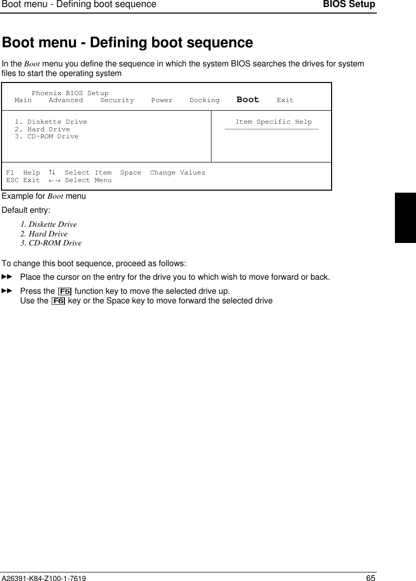
![Main menu - Making system settings BIOS SetupA26391-K84-Z100-1-7619 47Boot Options - System startup optionsThis field calls the submenu to select the settings for the system startup of the device. Phoenix BIOS Setup Main Boot Options Item Specific Help Summary screen: [Enabled] Floppy check: [Disabled] Quiet Boot: [Enabled] F1 Help ↑↓ Select Item Space Change Values F9 Setup Defaults ESC Exit ← → Select Menu Enter Select Sub-Menu F10 Previous ValuesExample for submenu Boot OptionsSummary screen - Displaying the configuration at system startupThis field is used to specify whether the configuration is displayed at system startup.Enabled The configuration is displayed when the device is switched on.Disabled The configuration is not displayed when the device is switched on.Floppy check - Checking the disk driveThis field can make the system startup faster.Enabled The entire notebook configuration is checked when the notebook is switched on.Disabled The disk drive is not checked in the self-test when the device is switched on.Quiet BootInstead of a start information a logo is displayed on the screen.Enabled The logo is displayed on the screen. A switch to the start information is made if youpress the key or if errors occur.Disabled The start information is displayed on the screen.System Memory - Main memoryThis field indicates the size of the available base memory below 1 Mbyte.Extended MemoryThis field indicates the size of the memory above 1 Mbyte.](https://usermanual.wiki/Fujitsu-Technology-Solutions/MOB75001/User-Guide-26802-Page-47.png)
![BIOS Setup Advanced menu - Advanced system settings48 A26391-K84-Z100-1-7619Advanced menu - Advanced system settings!Change the default settings only for special applications. Incorrect settings can causemalfunctions.You can make the following system settings in the Advanced menu:• Ports and controllers (in the Integrated Peripherals submenu)• PCI configuration ( in the PCI Devices submenu)• Second-level cache (in the Memory Cache submenu)• Plug&Play functionality (in the Plug and Play O/S field)• Configuration data (in the Reset Configuration Data field)• Hard disk access (in the Large Disk Access Mode field) Phoenix BIOS Setup Main Advanced Security Power Docking Boot Exit Warning! Setting items on this menu to incorrect values may cause your system to malfunction. Integrated Peripherals PCI Devices Plug & Play O/S: [Yes] Enable ACPI [No] Reset Configuration Data: [No] Large Disk Access Mode: [DOS] Item Specific Help—————————————————————— F1 Help ↑↓ Select Item Space Change Values F9 Setup Defaults ESC Exit ← → Select Menu Enter Select Sub-Menu F10 Previous ValuesExample for the Advanced menu](https://usermanual.wiki/Fujitsu-Technology-Solutions/MOB75001/User-Guide-26802-Page-48.png)
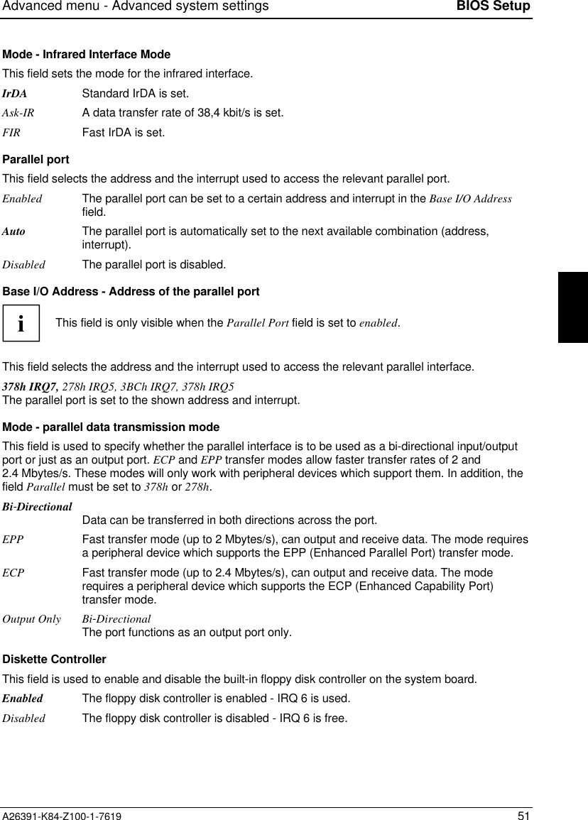
![Advanced menu - Advanced system settings BIOS SetupA26391-K84-Z100-1-7619 49Integrated Peripherals - Ports and controllersThis field calls the submenu to make the settings for the ports and controllers. Phoenix BIOS Setup Advanced Integrated Peripherals Item Specific Help PS/2 Mouse [Auto Detect] COM port: [Enabled] Base I/O Address: [3F8 IRQ4] IrDA port: [Auto] Mode: [IrDA] Parallel port [Auto] Mode: [Bi-Directional] Diskette Controller: [Enabled] On board IDE Adapter: [Both] On Board Audio: [Auto] Base I/O Address: [220] IRQ Channel: [IRQ 5] Capture DMA channel: [DMA 1] Playback DMA channel: [DMA 3] FM I/O: [388] MPU I/O: [300] Joystick: [Enabled] FM I/O: [201] QuickPort Audio Speaker: [Notebook] Microphone: [Notebook] F1 Help ↑↓ Select Item Space Change Values F9 Setup Defaults ESC Exit ← → Select Menu Enter Select Sub-Menu F10 Previous ValuesExample for the submenu Integrated PeripheralsPS/2 MouseThis field determines whether the PS/2 mouse or the touchpad is enabled on the notebook.Enabled The internal touchpad is activated if no PS/2 mouse is connected. If a PS/2 mouse isconnected when the system is started up, the PS/2 mouse is activated and the internaltouchpad is deactivated.Disabled The internal touchpad and the PS/2 mouse are disabled.You must set Disabled if you want to use an external serial mouse.Auto Detect The internal touchpad is activated if no PS/2 mouse is connected. If a PS/2 mouse isconnected when the system is started up, the PS/2 mouse is activated automaticallyand the internal touchpad is deactivated.](https://usermanual.wiki/Fujitsu-Technology-Solutions/MOB75001/User-Guide-26802-Page-49.png)
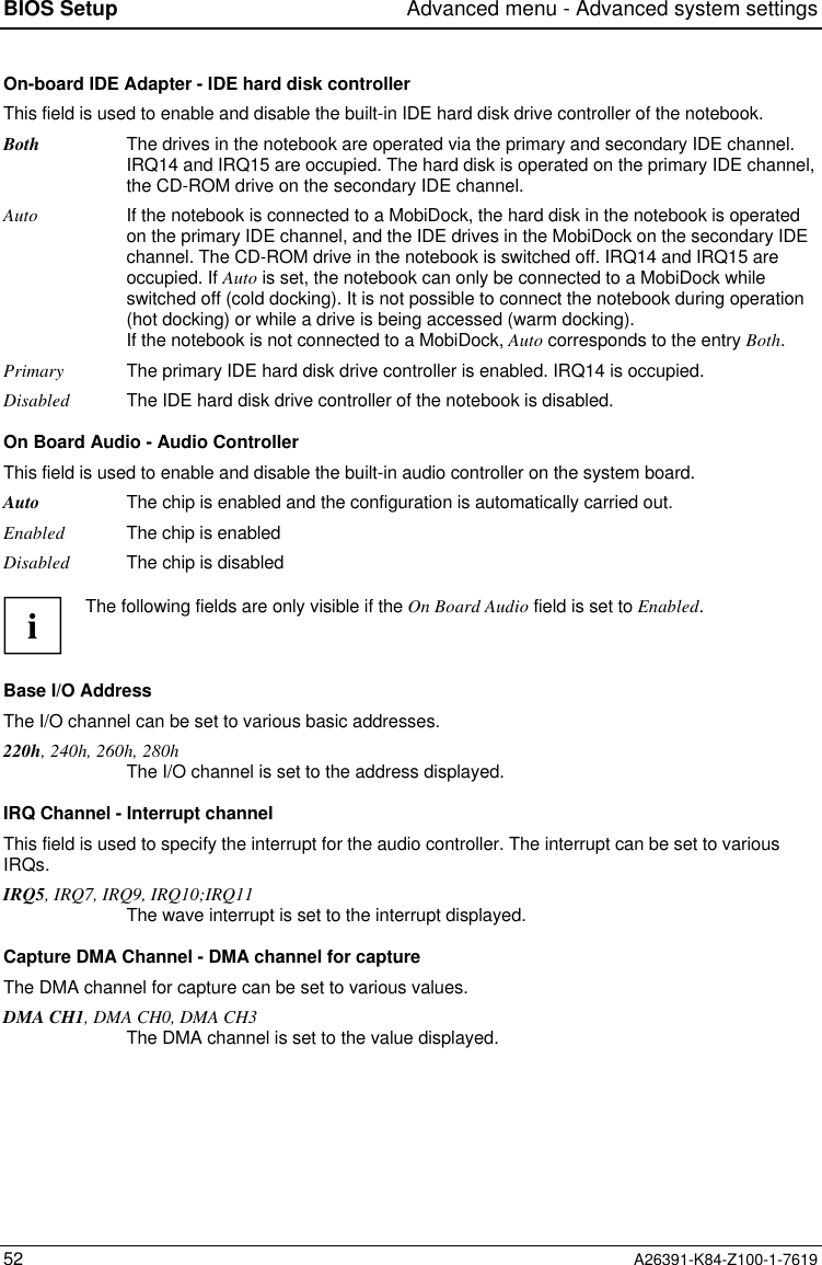
![BIOS Setup Advanced menu - Advanced system settings54 A26391-K84-Z100-1-7619PCI Devices - PCI configurationThis field calls the submenu to select the settings for the PC card controller and the PCI slots. Phoenix BIOS Setup Advanced PCI Devices Item Specific Help Cardbus Controller Select: [External/Internal] PCI IRQ line 1: [9] PCI IRQ line 2: [9] PCI IRQ line 3: [10] F1 Help ↑↓ Select Item Space Change Values F9 Setup Defaults ESC Exit ← → Select Menu Enter Select Sub-Menu F10 Previous ValuesExample for submenu PCI DevicesiIf you use an operating system that does not support plug & play, you must select No for thePlug&Play O/S field in the Advanced menu to ensure that the PC card controller is switchedon by the system BIOS.Cardbus Controller Select - Settings of the PC Card ControlleriThis setting is only effective when a QuickPort Plus or a QuickPort S is connected. If theQuickPort is not connected, the controller in the notebook is always configured to thecompatible address 3E0h.This field specifies the order of the CardBus controllerExternal/InternalThe controller in the QuickPort Plus/S is configured to the compatible address 3E0h. Asecondary address is assigned to the controller in the notebook.Internal/ExternalThe controller in the notebook is configured to the compatible address 3E0h. Asecondary address is assigned to the controller in the QuickPort Plus/S.External only The controller in the QuickPort Plus/S is configured to the compatible address 3E0h.The controller of the notebook is disabled.](https://usermanual.wiki/Fujitsu-Technology-Solutions/MOB75001/User-Guide-26802-Page-54.png)
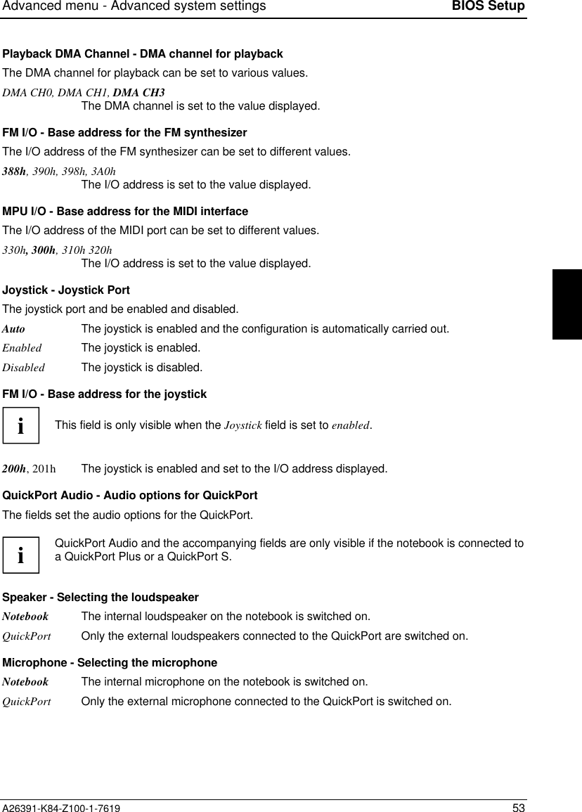
![Security menu - Setting up the security features BIOS SetupA26391-K84-Z100-1-7619 57Security menu - Setting up the security featuresYou can set up the following security features in the Security menu:• Setting a supervisor password (in the field Set Supervisor password)• Setting a user password (in the field Set User password)• Set a hard disk password (in the Hard Disk Security submenu)• Activating the password query for system startup (in the field Password on boot)• Blocking access to the diskette (in the field Diskette access) Phoenix BIOS Setup Main Advanced Security Power Docking Boot Exit Supervisor Password is Disabled User Password is Disabled Set Supervisor Password [Press Enter] Set User Password Press Enter Hard Disk Security Password on boot: [Disabled] Diskette access: [User] Flash Update: [Disabled] Item Specific Help—————————————————————— F1 Help ↑↓ Select Item Space Change Values F9 Setup Defaults ESC Exit ← → Select Menu Enter Select Sub-Menu F10 Previous ValuesExample for Security menuSupervisor Password is/User Password is - Password displayDisabled, EnabledThese fields indicate whether the appropriate password is installed or not.Set Supervisor PasswordThis field enables you to install the supervisor password.Set User PasswordThis field enables you to install the user password. However, you can only assign the user password ifa supervisor password has already been assigned.](https://usermanual.wiki/Fujitsu-Technology-Solutions/MOB75001/User-Guide-26802-Page-57.png)
![BIOS Setup Security menu - Setting up the security features58 A26391-K84-Z100-1-7619Hard Disk Security - Setting hard disk passwordsThis field calls the submenu to make the settings for the hard disk passwords. Phoenix BIOS Setup Security Hard Disk Security Item Specific Help HD1 Password is: Disabled Set HD1 password: [Press Enter] F1 Help ↑↓ Select Item Space Change Values F9 Setup Defaults ESC Exit ← → Select Menu Enter Select Sub-Menu F10 Previous ValuesExample for submenu PCI DevicesHD1 Password isDisabled, EnabledThis field indicates whether the appropriate password is installed or not.Set HD1 passwordThis field enables you to install the hard disk password. The hard disk password only applies to thehard disk in the notebook and not the one in the MobiDock. If a hard disk password has already beenset, you must enter the set password before you can change or delete it.Password on boot - Password query during system startupRequirement: the supervisor password or user password must be installed.This field is used to specify whether the password is to be queried when the operating system isbooted.Disabled The password is queried only when BIOS Setup is called.Enabled The password is queried before the operating system is booted and when BIOS Setup iscalled.Diskette access - Access privilege for disk driveThis field is used to specify whether diskettes can be accessed.User Both users and the supervisor can access diskettes.Supervisor Only a supervisor can access diskettes.Flash update - Permission for BIOS updateThis field specifies whether a BIOS flash update may be carried out on the notebook.Disabled BIOS flash update not possible.Enabled BIOS flash update is permitted.](https://usermanual.wiki/Fujitsu-Technology-Solutions/MOB75001/User-Guide-26802-Page-58.png)
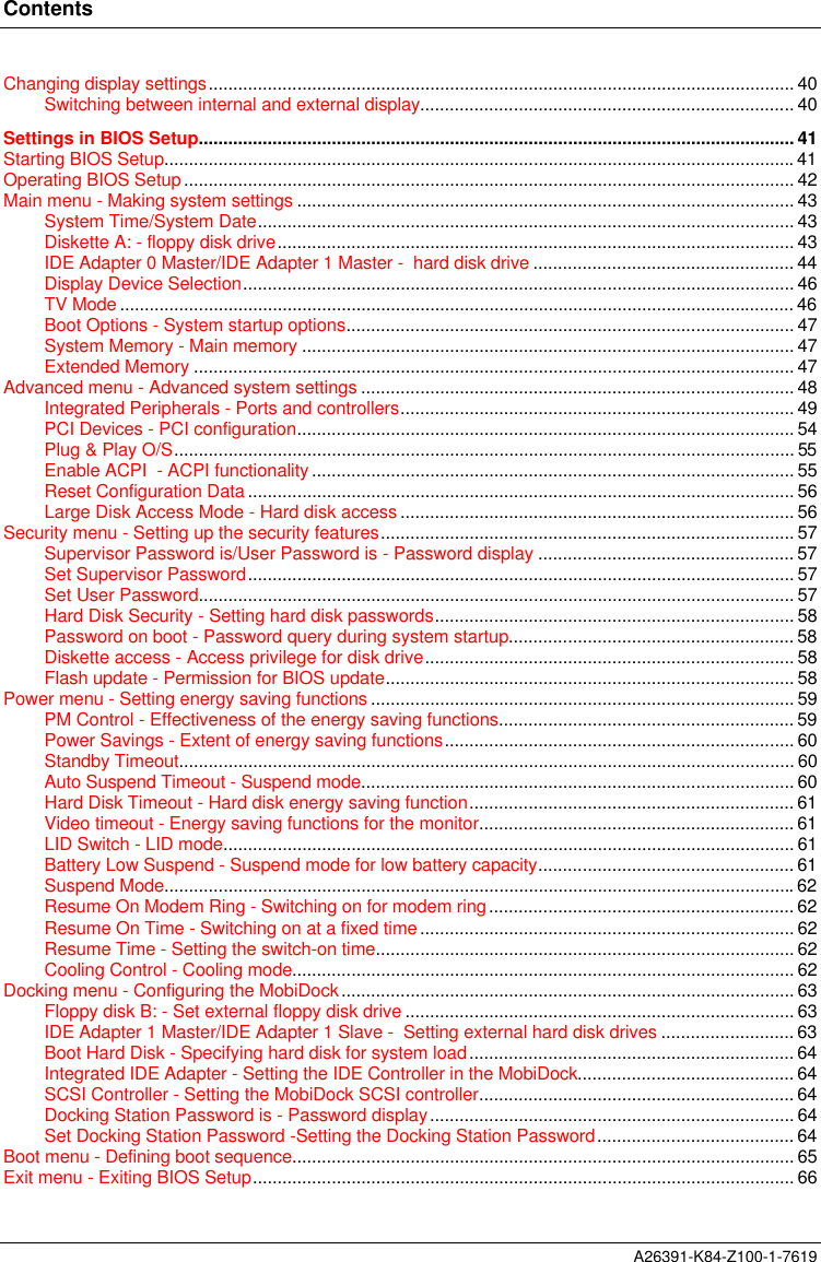
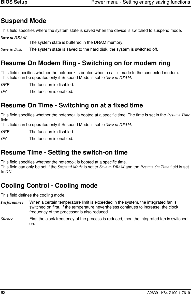
![Power menu - Setting energy saving functions BIOS SetupA26391-K84-Z100-1-7619 59Power menu - Setting energy saving functionsYou can set up the following energy saving functions in the Power menu• Effectiveness of energy saving functions (in the PM Control field)• Extent of energy saving functions (in the Power Savings field)• Standby timer (in the Standby Timeout field)• Suspend timer (in the Suspend Timeout field)• Automatic display power-down in the Video Timeout field)• Select the mode of the LID switch (in field of LID switch)• Enter suspend mode if the battery capacity is low (in the Battery Low Suspend field)• Suspend mode selection (in the Suspend Mode field)• Resume condition selection(in the Resume On Modem Ring, Resume On Time, Resume Time fields) Phoenix BIOS Setup Main Advanced Security Power Docking Boot Exit PM Control: [Battery Powered Only] Power Savings: [Customize] Standby Timeout: [5 min] Auto Suspend Timeout: [10 min] Hard Disk Timeout: [2 min] Video Timeout: [2 min] LID Switch: [LCD off] Battery Low Suspend: [Enabled] Suspend Mode: [Save to DRAM] Resume On Modem Ring: [OFF] Resume On Time: [OFF] Resume Time: [00:00:00] Cooling Control: [Performance] Item Specific Help—————————————————————— F1 Help ↑↓ Select Item Space Change Values F9 Setup Defaults ESC Exit ← → Select Menu Enter Select Sub-Menu F10 Previous ValuesExample for menu PoweriIf the field Enable ACPI is set to Yes, the energy saving functions are not controlled by theBIOS, but instead by the operating system.PM Control - Effectiveness of the energy saving functionsThis field determines when the energy saving functions are active.Battery Powered OnlyThe energy saving functions are only enabled for battery operation.Always Enable The energy saving functions are always enabled (battery and mains operation).Disabled None of the energy saving functions is effective.](https://usermanual.wiki/Fujitsu-Technology-Solutions/MOB75001/User-Guide-26802-Page-59.png)
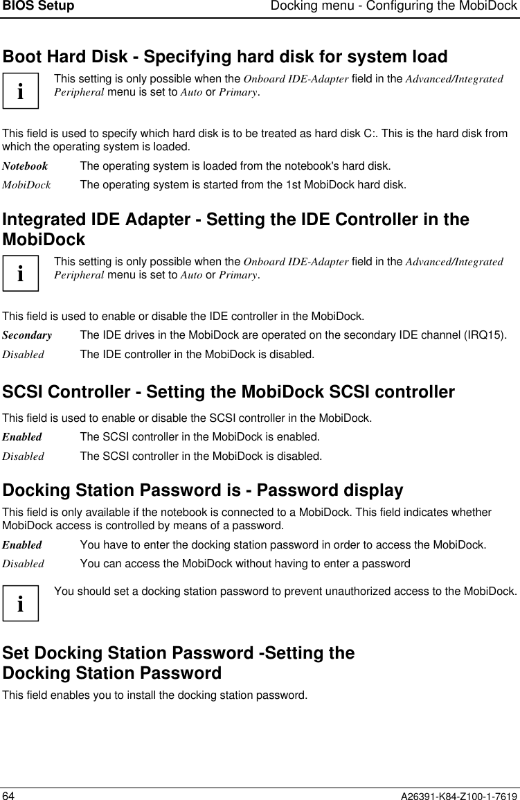
![Docking menu - Configuring the MobiDock BIOS SetupA26391-K84-Z100-1-7619 63Docking menu - Configuring the MobiDockThe Docking menu is only available if the notebook is connected to a MobiDock.You can set up the following security features in the Docking menu• external floppy disk drive (in the Diskette B: field)• external hard disk drive (in the fields marked IDE Adapter 1)• loading the system from hard disk C: (in the Boot Hard Disk field)• MobiDock password (in the Docking Station Password is field) Phoenix BIOS Setup Main Advanced Security Power Docking Boot Exit Diskette B: [Not installed] IDE Adapter 1 Master [None] IDE Adapter 1 Slave [None] Boot Hard Disk: [Notebook] Integrated IDE adapter [Secondary] SCSI Controller: [Enabled] Docking Station Password is [Disabled] Set Docking Station Password [Press Enter] Item Specific Help—————————————————————— F1 Help ↑↓ Select Item Space Change Values F9 Setup Defaults ESC Exit ← → Select Menu Enter Select Sub-Menu F10 Previous ValuesExample of the Docking menuFloppy disk B: - Set external floppy disk driveThis field shows the type of the floppy disk drive in the MobiDock.Not Installed A floppy disk drive is not installed.360KB - 5 1/4", 720KB - 3 1/2", 1.2MB - 51/4", 1.4MB - 3 1/2", 2.8MB - 3 1/2"The entry depends on the floppy disk drive in the MobiDock.IDE Adapter 1 Master/IDE Adapter 1 Slave -Setting external hard disk drivesiThis setting is only possible when the Onboard IDE-Adapter field in the Advanced/IntegratedPeripheral menu is set to Auto or Primary.This field shows the type of the hard disk drive in the MobiDock. How to change the settings for thehard disk drives is described in the IDE Adapter 0 field of the Main-Setup.](https://usermanual.wiki/Fujitsu-Technology-Solutions/MOB75001/User-Guide-26802-Page-63.png)
![Property and data protection68 A26391-K84-Z100-1-7619Setting passwordsThe Supervisor password prevents unauthorized callup of BIOS Setup. BIOS Setup can be called only bythose who know the Supervisor password.The user password prevents unauthorized access to your notebook. With the user password you canprevent booting of the operating system. The system can be accessed only by those who know theuser password. A user password can only be set if a supervisor password is also set.iPasswords can be at most seven characters long. All alphanumerical characters can beused; no differentiation is made between upper-case and lower-case.Passwords are not displayed as they are entered.If you have forgotten a password contact your system administrator or contact our customerservice.To set or change a password, proceed as follows:Call BIOS Setup and select the Security menu (see "Settings in BIOS Setup"). You mustadditionally change into the Hard Disk Security submenu for the hard disk passwords.Mark the Set Supervisor Password or Set User Password or Set HD password field and press theEnter key.The following applies for setting a hard disk password: if a hard disk password is already set, you areprompted to input it. Enter the former hard disk password and press the Enter key.You are asked to enter a password:Enter new Password:Enter the password and press the Enter key.You are asked to confirm the password:Re-enter new Password:Enter the password again and press the Enter key.The new password is saved.Notice: Changes have been saved [continue]To prevent booting of the operating system, mark the Password on boot field and select the valueEnabled.If you do not want to make any other settings, you can exit BIOS Setup.Select the option Save Changes & Exit in the Exit menu.The notebook is rebooted and the new password is effective.](https://usermanual.wiki/Fujitsu-Technology-Solutions/MOB75001/User-Guide-26802-Page-68.png)