Fujitsu Technology Solutions MOB75001 User Manual A26391 K84 Z100 1 7619
Fujitsu Technology Solutions GmbH A26391 K84 Z100 1 7619
Mobile 750 Operating Manual August 1998 Edition

A26391-K84-Z100-1-7619 1
Introduction
Innovative technology and ergonomic design make this notebook the ideal user-friendly and reliable
travel companion. Your operating system is pre-installed on the hard disk to facilitate the procedure
when you use your notebook for the first time.
The energy-saving processor and the energy-saving functions that can be configured allow you to use
the battery capacity of your notebook effectively. By using an additional battery instead of the disk
drive, you can double the notebook’s mobile operation time.
Your notebook has 32 - 192 MB of main memory installed, depending on the upgrade level. Data is
saved on an Enhanced-IDE hard disk drive. Your notebook is also equipped with a 3 1/2" floppy disk
drive and a CD-ROM drive. In addition, your notebook can be equipped with a DVD drive or with a 2ndd
hard disk drive. Two PC card slots (CardBus or PCMCIA) enable the notebook to operate two type II
PC cards or one type III PC card.
For mouse control the notebook provides a touchpad. A double-touch directly on the touchpad is all
that is needed, for example, to open an application.
Your notebook has connectors for external devices such as, e.g. external monitor, printer and mouse.
The parallel port (which supports ECP and EPP modes) is designed to accommodate bi-directional
data transfer. You can connect peripherals such as, e. g. scanner, loudspeakers, gamepads, keyboard
or mouse via the USB interface.
The notebook disposes of a infrared interface for wireless data transfer.
In addition, the notebook has a connection port for a MobiDock or a QuickPort.
An audio controller, two loudspeakers, a microphone, an audio input and output and a loudspeaker
output provide your notebook with an audio capability. You can thus incorporate voice, noise effects
and music into your notebook environment. You can also connect an external microphone and an
external loudspeaker.
The system settings of the notebook can be configured via the user-friendly BIOS Setup program.
Certain system settings (e.g. screen display, power-management functions) can be modified via
various key combinations while you are using the notebook.
Your notebook has a number of security features to ensure that no unauthorized persons can access
your data. For example, you can activate a screen saver with password protection. The security
functions in the BIOS Setup also allow you to protect your data by means of passwords.
This Operating Manual tells you how to put your notebook into operation and how to operate it in daily
use.
Further information on this notebook is provided:
• in the "Safety Notes" manual which is included with your notebook
• in the documentation of your operating system
• on the SCENIC Mobile CD "Drivers & Utilities"
• in the information files (e. g. *.TXT, *.WRI, *.DOC, *.HLP)
• on the Internet under www.sni-pc.de/drivercd
Introduction Notational conventions
2A26391-K84-Z100-1-7619
Notational conventions
The meanings of the symbols and fonts used in this manual are as follows:
!Pay particular attention to texts marked with this symbol. Failure to observe this warning
endangers your life, destroys the notebook, or may lead to loss of data.
iThis symbol is followed by supplementary information, remarks and tips.
Texts which follow this symbol describe activities that must be performed in the order shown.
Texts in this typeface are screen outputs from the PC.
Texts in italics indicate commands or menu item.
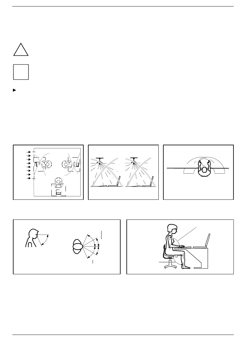
Installing an ergonomic video workstation
Before you set up your equipment you should select a suitable position for working at the monitor.
Please observe the following advices when installing a video workstation.
Window
permissible
reachin
g
sector
600 mm
ed
g
e of desk
permissible
reachin
g
sector
600 mm
Avoid direct and reflected glare. Avoid glare from electric lighting. Position the keyboard where it is
easiest to reach.
30°
30°
65°
65°
0°
60°
preferable viewin
g
sector
permissible viewin
g
sector
permissible
viewing sector approx. 90°
and
more
approx. 90°
Position the monitor for optimum viewing. The
viewing distance to the monitor should be
approximately 50 cm.
Remember to maintain correct posture.

A26391-K84-Z100-1-7619 3
Important notes
In this chapter you will find information regarding safety which it is essential to take note of when
working with your notebook. The manufacturer's notes contain helpful information on your notebook.
This chapter also contains information on the licenses like CE certificate and RFI suppression of the
notebook.
Safety
!Pay attention to the information provided in the manual "Safety Notes".
• During installation and before operating the device, observe the instructions on environmental
conditions in the chapter entitled "Technical data" as well as the instructions in the chapter
"Preparation for use and operation".
• When cleaning the device, observe the relevant notes in the paragraph "Cleaning the notebook".
• Keep this Operating Manual together with your device. If you pass on the device to third parties,
you should also pass on this manual.
Notes on installing and removing boards and modules
!Only qualified technicians may repair the device. Unauthorized opening or incorrect
repair may greatly endanger the user (electric shock, fire risk).
Boards with electrostatic sensitive devices (ESD) may be identified by the
label shown.
When you handle boards fitted with ESDs, you must observe the following
points under all circumstances:
• You must always discharge yourself (e.g. by touching a grounded object)
before working.
• The equipment and tools you use must be free of static charges.
• Pull out the power plug before inserting or pulling out boards containing
ESDs.
• Always hold boards with ESDs by their edges.
• Never touch pins or conductors on boards fitted with ESDs.

Important notes Manufacturer’s notes
4A26391-K84-Z100-1-7619
Manufacturer’s notes
Energy saving
Make use of the device's power management features (see "Preparation for use and operation").
• If you will not be using your notebook, switch it off.
• The notebook uses less power when the power management features are enabled. You will then
be able to work for longer before having to recharge the battery.
Energy saving under Windows
If a monitor with energy saving features is connected to your notebook, you can use the Screen Saver
tab to set the energy saving features of the monitor. Select the following item in the start menu: Settings
- Control Panel - Display - Display Properties - Screen Saver - Energy saving features of monitor. You can
set additional energy saving functions in the Start - Settings - System control - Energy - Extended menu.
Disposal and recycling
This device has been manufactured to the greatest possible degree from materials which can be
recycled or disposed of in a manner that is not environmentally damaging. The device is taken back
after use, so that it can be recycled, provided that it is returned in a condition which is the result of
normal use. Any components not recuperated will be disposed of in an environmentally acceptable
manner.
For devices marked with this symbol Siemens AG offers a guarantee for
36 months with a Bring-in-Service. The guarantee starts on the day of
delivery (sale date) by Siemens or a Siemens partner.
We herewith declare that it will be possible to repair any device marked
with the eco-label for at least 5 years after production of that device has
discontinued.
Information on power management and energy saving mode can be
found in chapter "Technical data".
Do not throw lithium batteries or accumulators into the trashcan. They must be disposed of in
accordance with local regulations concerning special waste.
If you have any questions on disposal, please contact your local office, our service department, or,
directly:
Siemens AG
Recycling Center
D-33094 Paderborn
Tel.: ..49 5251 818010
Fax: ..49 5251 818015
CE certificate
The shipped version of this device complies with the requirements of the EEC directives
89/336/EEC "Electromagnetic compatibility" and 73/23/EEC "Low voltage directive".

FCC Class B Compliance Statement Important notes
A26391-K84-Z100-1-7619 5
FCC Class B Compliance Statement
If there is an FCC statement on the device, then:
The following statement applies to the products covered in this manual, unless otherwise specified
herein. The statement for other products will appear in the accompanying documentation.
NOTE:
This equipment has been tested and found to comply with the limits for a "Class B" digital device,
pursuant to Part 15 of the FCC rules and meets all requirements of the Canadian Interference-Causing
Equipment Regulations. These limits are designed to provide reasonable protection against harmful
interference in a residential installation. This equipment generates, uses and can radiate radio
frequency energy and, if not installed and used in strict accordance with the instructions, may cause
harmful interference to radio communications. However, there is no guarantee that interference will not
occur in a particular installation. If this equipment does cause harmful interference to radio or television
reception, which can be determined by turning the equipment off and on, the user is encouraged to try
to correct the interference by one or more of the following measures:
• Reorient or relocate the receiving antenna.
• Increase the separation between equipment and the receiver.
• Connect the equipment into an outlet on a circuit different from that to which the receiver is
connected.
• Consult the dealer or an experienced radio/TV technician for help.
Siemens AG is not responsible for any radio or television interference caused by unauthorized
modifications of this equipment or the substitution or attachment of connecting cables and equipment
other than those specified by Siemens AG. The correction of interferences caused by such
unauthorized modification, substitution or attachment will be the responsibility of the user.
The use of shielded I/O cables is required when connecting this equipment to any and all optional
peripheral or host devices. Failure to do so may violate FCC rules.
Important notes Power cord selection
6A26391-K84-Z100-1-7619
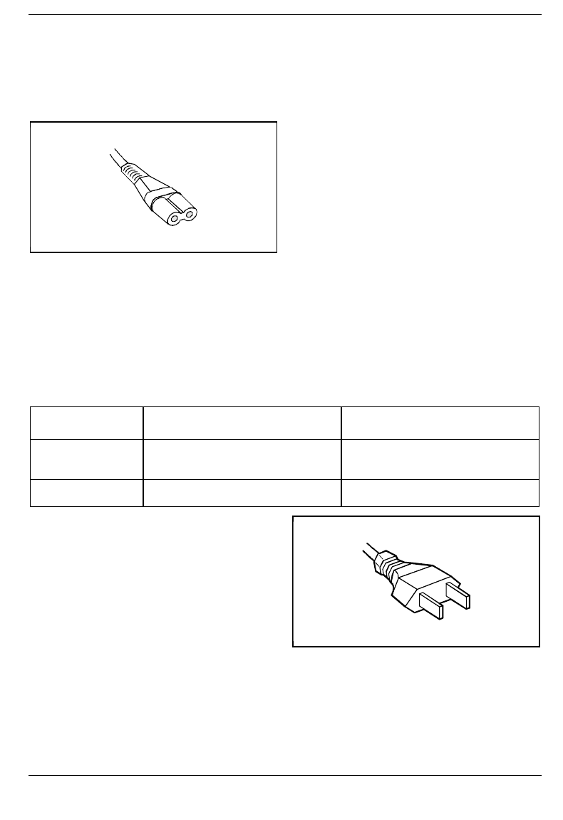
Power cord selection
The power cord for this unit has been packed separately and has been selected according to the
country of destination. It must be used to prevent electric shock. Use the following guidelines if it is
necessary to replace the original cord set.
The female receptacle of the cord set must meet
IEC 320 requirements.
For the United States and Canada
Use a UL listed and CSA labeled cord set consisting of a two conductor cord with a maximum length of
15 feet.
For units which stand on a desk or table, type SVT or SJT cord sets shall be used.
For units which stand on floor, only SJT type cord sets shall be used.
The cord set must be selected according to the current rating for your unit. Please consult Table A for
the selection criteria for power cords used in the United States and Canada.
Table A:
Cord Type Size of Conductors
in Cord Maximum Current
Rating of Unit
SJT 18 AWG
16 AWG
14 AWG
10 Amps
12 Amps
12 Amps
SVT 18 AWG
17 AWG 10 Amps
12 Amps
For units set at 115 V:
use a parallel blade attachment plug rated 15 A,
125 V.
For units set at 230 V (outside of the United States and Canada):
use a cord set consisting of a minimum AWG according to Table A and an attachment plug rated 15 A,
250 V. The cord set should have the appropriate safety approvals for the country in which the
equipment will be installed and should be marked HAR.

On the move with the notebook Important notes
A26391-K84-Z100-1-7619 7
On the move with the notebook
Please observe the points listed below when transporting your notebook.
Transporting the notebook
• Do not carry the notebook by its open screen or by an empty slot.
• Switch off the notebook.
• Remove all data carriers (e.g. floppy disk, CD) from the drives.
• Always use the bag supplied when transporting the notebook.
If it needs to be shipped, use the original packaging or other suitable packaging to protect it from
damage through mishandling.
• The carrying bag provided protects against dust, but offers no protection against jolts or impacts.
• Protect the notebook from severe shocks and extreme temperatures (e.g., direct sunlight in a
car).
Before starting the journey
• Copy important data from the hard disk to a floppy disk.
• Remove all data carriers (e.g. floppy disk, CD) from the drives.
• If you wish to use your notebook during a flight, check first with the flight attendants if it is
permissible to do so.
• If you are travelling abroad, ensure that the power adapter can be operated on the local line
voltage. If this is not the case, obtain the appropriate power adapter for your notebook.
Do not use any other voltage converter!

Important notes Cleaning the notebook
8A26391-K84-Z100-1-7619
Cleaning the notebook
!Switch the notebook off and pull the power plug of the power adapter out of the power
socket.
Do not clean any interior parts yourself, leave this job to a service technician.
Do not use any cleaning agents that contain abrasives or may corrode plastic.
Ensure that no liquid enters the notebook.
Wipe the casing with a dry cloth. If particularly dirty, use a cloth which has been moistened in mild
domestic detergent and then carefully wrung out.
To clean the keyboard and the touchpad, you can use disinfectant wipes..
Wipe the monitor casing with a soft, moistened cloth.
Unpacking and checking the delivery Preparation for use and operation
A26391-K84-Z100-1-7619 9
Preparation for use and operation
!Pay attention to the chapter "Important notes".
You must charge the battery and install the application programs before you can work with the
notebook. The operating system and required drivers are preinstalled.
When used away from a wall power outlet, the notebook runs on its built-in battery. You can increase
battery life by enabling its power management features.
If you use the notebook in a normal office situation, you run it off the mains with the aid of the power
adapter, or in a MobiDock or QuickPort/QuickPort/Plus.
Refer to the chapter on "System expansions" for instructions on how to connect external devices (e.g.
mouse, printer) to the notebook.
Unpacking and checking the delivery
Unpack all the individual parts.
Check the delivery for damage incurred during transport.
Check whether the delivery agrees with the details in the delivery note.
Check whether all necessary details have been entered on the first page of the guarantee coupon
booklet.
Should you discover that the delivery does not correspond to the delivery note, notify your local sales
office immediately.
iDo not discard the original packing material of the devices. Keep it for future transportation of
the drive.
Choosing where to set up your notebook
Select a suitable location for the notebook before setting it up. Bear the following points in mind when
looking for a location.
• We recommend that you place your notebook on a surface with good anti-slip qualities. In view of
the multitude of different finishes and varnishes used on furniture, it is possible that the rubber feet
of the devices will mark the surface they stand on.
• Do not expose the notebook to extreme environmental conditions. Protect it from dust, humidity
and heat.
• Keep other objects 100 mm clear of the notebook and its power adapter to ensure adequate
ventilation. The space between the notebook's feet must be clear. Do not place it on a soft
surface (e.g., a carpet or soft furnishings).
• The power adapter must be at least 200 mm away from the notebook. It must be free-standing
and may not be covered. Do not stand the power adapter on heat-sensitive material.
Preparation for use and operation Preparing the notebook for use
10 A26391-K84-Z100-1-7619
• For wireless data transfer you must align the notebook's infrared interface with that of the partner
device (e.g. PC). The devices must not be more than one meter apart.
Preparing the notebook for use
!The supplied power cord conforms to the requirements of the country in which you
purchased your notebook. Make sure that the power cable is approved for use in the country
in which you intend to use it.
The notebook and the power adapter should be at least 200 mm apart. Keep other objects
100 mm clear of the notebook and its power adapter.
Do not cover the ventilation slots in the notebook.
Place the notebook on a level, stable surface.
Depending on the version, your notebook will be supplied with and internal or an external power
adapter.
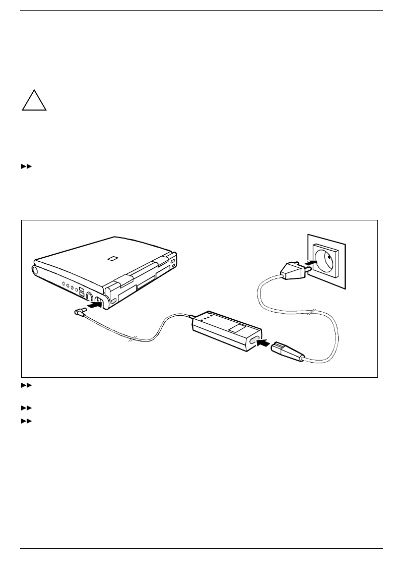
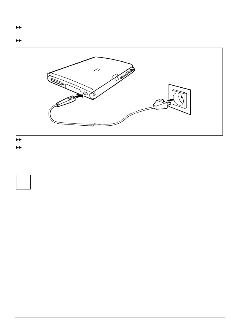
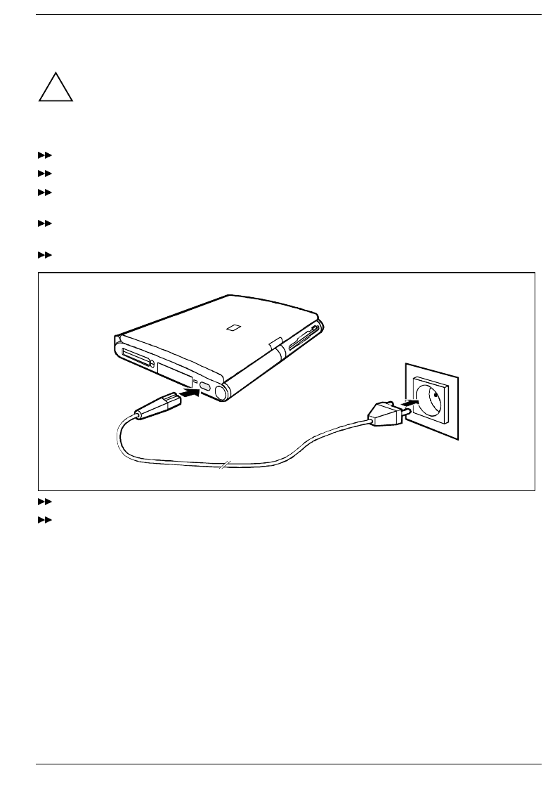
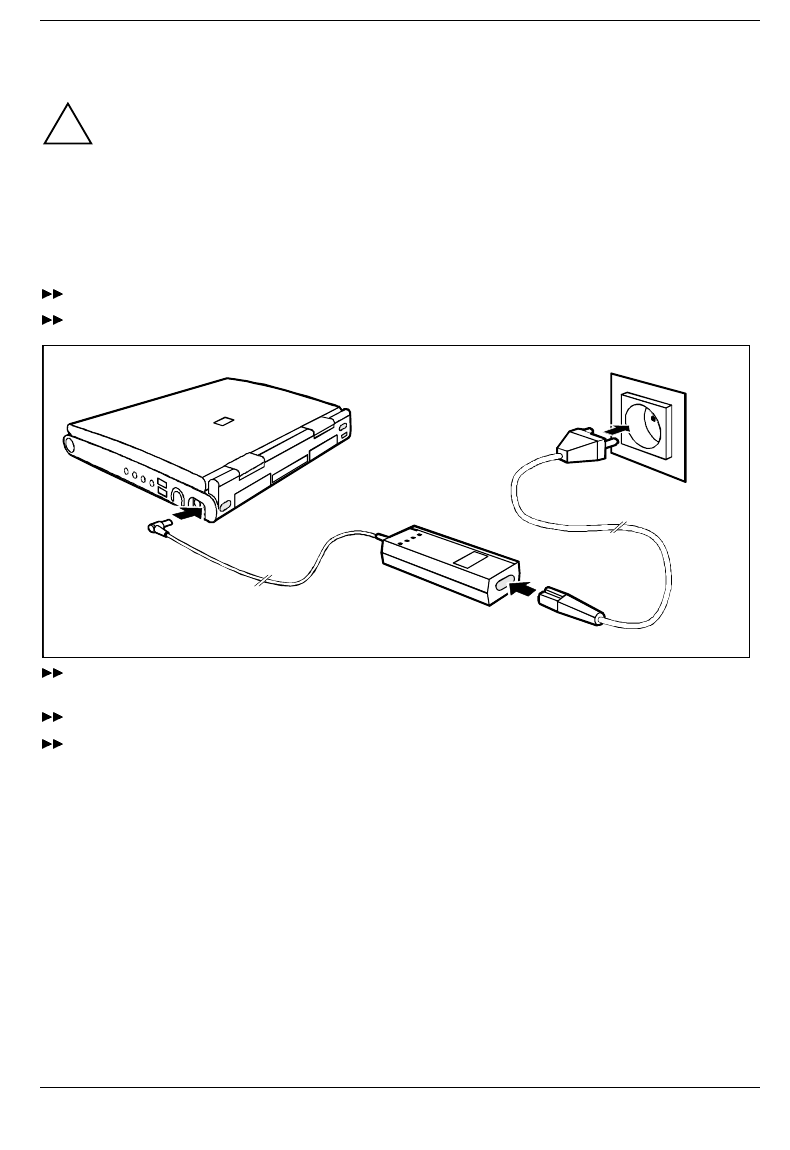
External power adapter
1
2
3
Plug the DC output connector on the power adapter into the DC input connector (DC IN) on the
notebook (1).
Connect the AC power cable to the power adapter (2).
Plug the power cable into the power outlet (3).
The power adapter indicator lights up.
Preparing the notebook for use Preparation for use and operation
A26391-K84-Z100-1-7619 11
Internal power adapter
Place the AC adapter in the left-hand slot so that the contacts enter first. The connector for the AC
adapter power cable must face outwards.
Push the AC adapter into the slot until you feel it locking into place.
12
Connect the power cable to the AC IN connector on the notebook (1).
Plug the power cable into the power outlet (2).
A battery built into the right slot is recharged in this configuration. A battery is fully charged in
approximately three hours if the notebook is switched on. If the notebook is switched on, it will charge
in roughly five to six hours.
iYou can also make your notebook operational by connecting it to the optional power
adapter or car adapter (see "Charging, caring for and maintaining the battery"). The
AC adapter can also be operated as an external power adapter (see "Using AC
adapter as external power adapter").
Preparation for use and operation Preparing the notebook for use
12 A26391-K84-Z100-1-7619
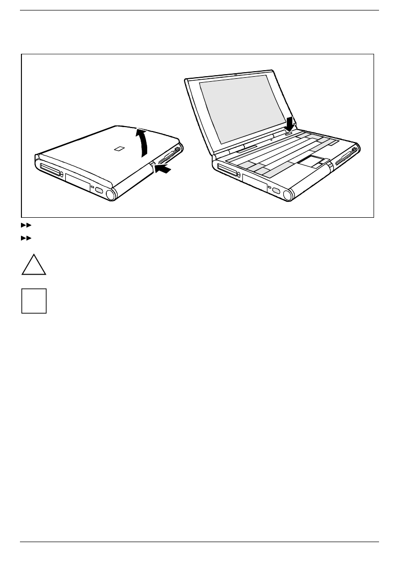
Switching on the notebook
1
2
3
Press the release button (1) and unfold the display upwards (2).
Press the ON/OFF switch (3) for roughly one second.
!You must not switch off or warm-boot your notebook during first-time installation .
iWhen you switch on your notebook for the first time the supplied software is set up and
configured. Please follow the instructions on the screen.
If you want to partition your hard disk, please refer to chapter "Restoring the hard disk
contents under Windows 9x".
If you have assigned a password, you must enter this when requested to do so, in order to
start the operating system.
Notes on Windows
The license number for Windows is printed on the front cover of the Windows manual supplied.
Indicators and input devices Preparation for use and operation
A26391-K84-Z100-1-7619 13
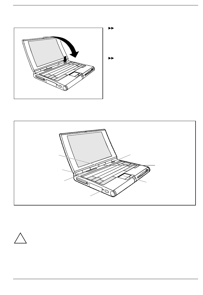
Switching off the notebook
12
Shut down the operating system properly. If
Windows 9x is installed on your notebook,
the system is shut down and the notebook is
switched off. If the notebook is not switched
off automatically, press the ON/OFF switch
(1) for approx. one second.
Close the display of the notebook (2) so that
it locks into place.
Indicators and input devices
4
2
1
3
5
1
6
1 = LCD lock
2 = LCD switch-off
3 = Touchpad with touchpad buttons
4 = Kensington Lock device
5 = Display field
6 = Battery indicator (right)
power-on indicator (left)
!Only release the LCD lock when required.
You can protect your notebook from theft with the Kensington Lock device (3) and with a
Kensington MicroSaver.
Battery indicator
Glows green: Battery is being charged
Glows red: Battery capacity is below 12% or battery is defective
Preparation for use and operation Indicators and input devices
14 A26391-K84-Z100-1-7619
Power-on indicator
Glows green: Notebook is switched on
Glows red: Processor is in idle mode
Glows orange: Processor operates at half frequency
Flashes: Notebook is in standby mode
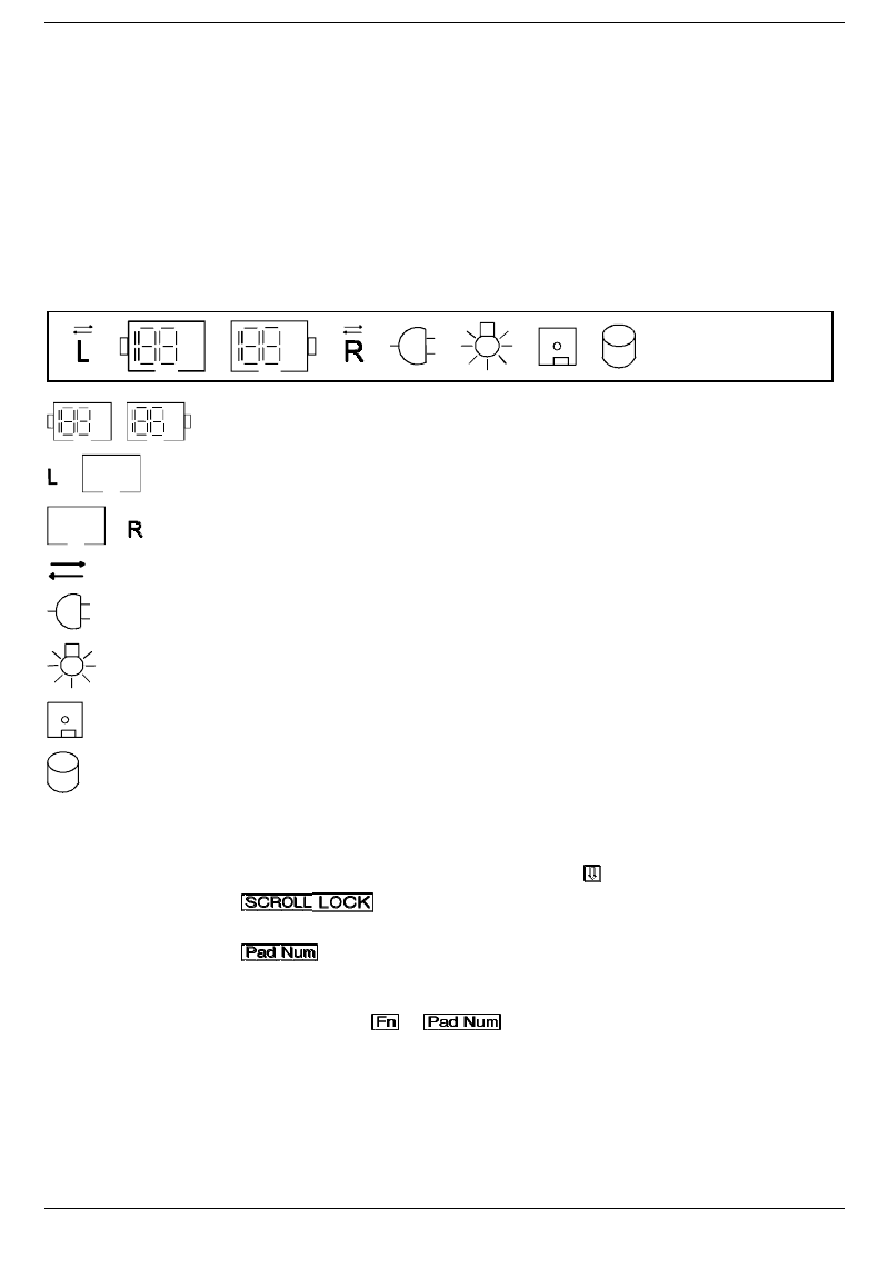
Display field
Symbols and texts in the display field indicate the operating state of the notebook. The meaning of the
symbols and texts are as follows:
CapsLk
NumLk ScrLk
PadLk
% %
% % Indicates the approximate capacity of the installed batteries in percent.
The left battery is installed. When the symbol flashes, the left battery is drained or
defective (for measures, see "Charging, caring for and maintaining the battery").
The right battery is installed. When the symbol flashes, the right battery is drained
or defective (for measures, see "Charging, caring for and maintaining the battery").
The arrow shows whether the battery is being charged or drained.
The notebook is connected to an external power source (e.g. via the power
adapter).
The notebook is switched to Suspend to DRAM mode.
The floppy disk in the floppy disk drive is being accessed. You must not remove
the floppy disk when this symbol is visible.
A drive (hard disk drive, CD-ROM drive, DVD drive or Zip drive) is being
accessed. When this symbol appears, do not remove the data carrier from the
drive.
CapsLK All the characters you type appear as uppercase. In the case of overlay keys, the
character on the upper left on the keycap appears when that key is pressed. The
CapsLock indicator appears when you press the key.
ScrLK The key has been pressed. The effect this key has varies from
program to program.
NumLK The key has been pressed. If PadLK is also visible in the function
display, the blue numbers on the lower right on keys in the integrated numeric
keypad are enabled.
PadLK The key combination + has been pressed.
Indicators and input devices Preparation for use and operation
A26391-K84-Z100-1-7619 15
Touchpad and Touchpad Keys
!Make sure that the touchpad does not come into contact with dirt, liquids or grease.
Do not touch the touchpad if your fingers are dirty.
Do not rest heavy objects (e.g., books) on the touchpad or the touchpad buttons.
The touchpad enables you to move the mouse pointer on the screen. If, for example, you move one
finger to the left over the touchpad, the mouse pointer also moves to the left.
A brief tap with the finger on the touchpad has the same effect as clicking with the left mouse button. A
brief "double-tap" with the finger on the touchpad has the same effect as double-clicking with the left
mouse button.
The left and right touchpad buttons have the same functions as the left and right mouse buttons.
iIf you attach and install an external mouse, the touchpad and its buttons are disabled. If you
attach an external serial mouse, you must select the Disabled option for the
PS/2 Pointing Device field in the Main Setup. This also releases interrupt 12, so that you can
use it for other applications.
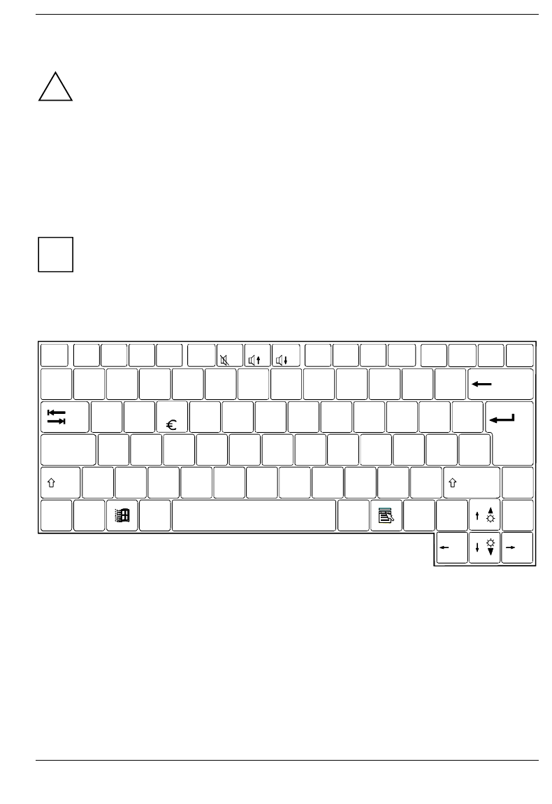
Keyboard
EscF1F2F3F4 F5 F6F7F8 F9F10F11F12
E
LCD/CRTCD slow LCD Off Suspend CPU slow Info LCD TV on/off
Ctrl
|
P
g
Dn
Fn
`
!
1
@
2
#
3
$
4
%
5
^
67 890-
QW RT Y UI OP{ }
A
Z
S
X
D
C
F
V
G
B
H
N
J
M
K
<
L
>?
:"
&
7
*
8
(
9
)
/
_+
=
]
456*
End
123-
0
,. /
+
Pause
Break
PrtScrn
SysRqPad Num
Alt Alt Gr Ins Del
Home
\
\
P
g
Up
[
,;
.
Lock
Scroll
Lock
Caps Lock
~
Standby
The following description of keys and key combinations refers to Windows 9x Additional functions
supported by the keys are described in the relevant manuals supplied with your application programs.
Preparation for use and operation Indicators and input devices
16 A26391-K84-Z100-1-7619
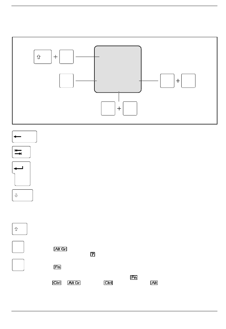
The figure below shows how to access the different characters on keys with overlaid functions. The
keystrokes shown in the example only work if CapsLK, NumLK, and PadLK have not been enabled (i.e.
they are not visible in the display field).
7
/
{7
7
/
{7
7
/
{7
Alt Gr 7
/
{7
Fn 7
/
{7
Example from a German keyboard
Backspace key
The Backspace key deletes the character to the left of the cursor.
Tab key
The Tab key moves the cursor to the next tab stop.
Enter key (return, enter, line feed, carria
g
e return)
The enter key terminates a command line. The command you have entered is
executed when you press Enter.
Caps Lock key
The Caps Lock key activates uppercase mode (CapsLK is shown in the display field).
The Caps Lock function causes all the characters you type to appear as uppercase. In
the case of overlay keys, the character on the upper left on the keycap appears when
that key is pressed.
To cancel the Caps Lock function, simply press the Caps Lock key again.
Shift key
The Shift key causes uppercase characters to appear. In the case of overlay keys, the
character on the upper left on the keycap appears when that key is pressed.
Alt Gr Alt Gr key
The key causes the characters in the lower middle of the keycap to appear
(e.g. in the case of the key).
Fn Fn
The key enables the special functions indicated in blue on overlay keys (see "Key
combinations").
If the external keyboard does not feature a key, you can simultaneously press
the + key or the key and the right key instead.
Indicators and input devices Preparation for use and operation
A26391-K84-Z100-1-7619 17
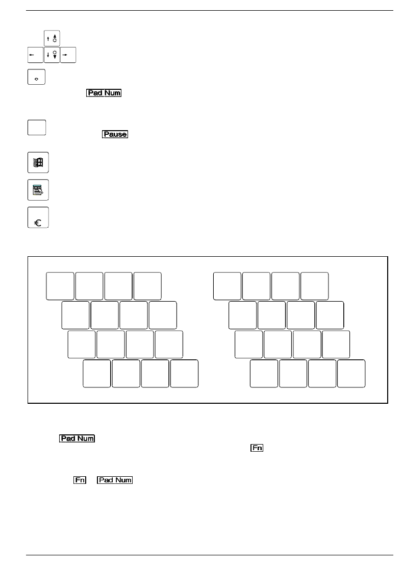
Cursor keys
The cursor keys move the cursor in the direction of the arrow, i.e., up, down, left, or
right.
Pad Num Pad Num key
When the numeric keypad is enabled (PadLK is visible in the display field), the
key causes this set of keys to produce numbers (NumLK appears in the
display field). Pressing them produces the blue characters shown on the bottom right
on the keycaps.
Pause
Break Pause key
The key temporarily suspends display output. Output will resume when press
any other key.
Start key
invokes the START menu of Windows.
Menu key
The Menu key invokes the menu for the marked item (Windows).
EEuro ke
y
The Euro-key produces the Euro character (Windows 98 and Windows NT5.0).
Numeric keypad
7 890
UI OP
J
M
K
;
L
:_
Ö
/
{
(
[
)
]
=
}
µ, . -
789 /
456*
123-
0+,
12
1 = Characters enabled when neither PadLK, nor NumLK are visible in the display field.
2 = Characters enabled when PadLK and NumLK are visible in the display field.
The key enables and disables the integrated numeric keypad. If the numeric keypad is
enabled (NumLK is shown in the display field) and you hold the key down, you can output the
characters printed in blue at the right bottom of the keys.
When the numeric keypad is enabled (NumLK is visible in the display field), pressing the key
combination + enables and disables the numeric entry in the integrated numeric
keypad. If numeric entry is enabled (NumLK and PadLK are shown in the display field), the blue
characters at the bottom right of the keys are effective.
Preparation for use and operation Indicators and input devices
18 A26391-K84-Z100-1-7619
If the numeric keypad and numeric entry are both enabled (NumLK and PadLK are shown in the
display field), you can also output standard characters with the numeric keypad. If you press and hold
the key , the keys will produce lowercase letters and numbers indicated on the lower left of the
keycaps. If you press and hold the key combination + Shift, the keys will produce uppercase
letters and the characters indicated on the upper left of the keycaps.
Key combination
The following description of keys and key combinations refers to Windows 9x Some of the following
key combinations may not function in other operating systems and with some device drivers.
Other key combinations are described in the relevant manuals supplied with your application programs.
You enter key combinations as follows:
Press and hold the first key in the combination.
While keeping the first key pressed, press the other key or keys in the combination.
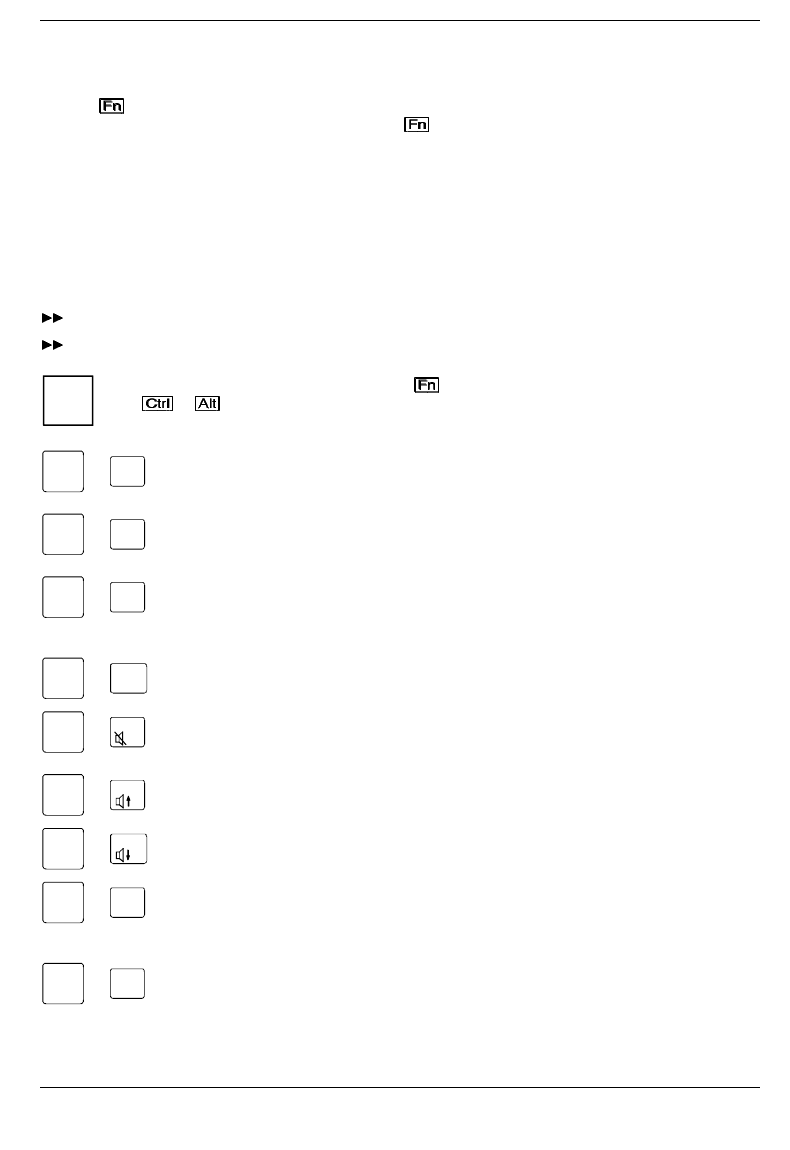
iIf the external keyboard does not feature a key, you can simultaneously press
the + keys instead.
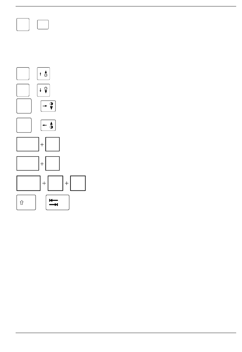
F1
LCD Off
Fn +Switchin
g
monitor on/off
This key combination switches your notebook's display on and off. Doing so does
not affect any running programs.
F3
Standby
Fn +Enablin
g
Standby mode
This key combination enables Standby mode. The power-on indicator flashes.
You can cancel Standby mode by pressing any key.
F4
Suspend
Fn +Enablin
g
Suspend mode
This key combination switches the Suspend mode on (see Section "Suspend
mode "). When you switch the notebook on again, it returns to the same place
you were in the program that was running when you switched to Suspend mode.
Fn F5
CPU slow
+Reducin
g
CPU speed
This key combination reduces the CPU speed by 50 %.
F6
Fn +Switchin
g
the loudspeaker on/off
This key combination switches your notebook's integrated loudspeaker on and
off.
F7
Fn +Increasin
g
the volume
This key combination raises the volume of the integrated loudspeaker.
F8
+
Fn Reducin
g
the volume
This key combination decreases the volume of the integrated loudspeaker.
F10
Info LCD
Fn +Switchin
g
over battery indicator
This key combination switches the battery indicator in the display field between
battery capacity in %, as time (notebook will still run xx:xx hours) or the battery
charge level display.
F11
TV on/off
Fn +Switchin
g
TV out on/off
This key combination switches the video output (TV out) on or off.
Indicators and input devices Preparation for use and operation
A26391-K84-Z100-1-7619 19
F12
LCD/CRT
Fn +Switchin
g
between internal and external display
If an external display is connected to your notebook, you can switch to it with this
key combination. You can opt to use:
• just the notebook's internal display
• just the external display
• both the internal and the external display
• just the television
• both the internal display and the television
Fn +Increasin
g
the display bri
g
htness
This key combination increases the brightness of the display.
Fn +Reducin
g
the display bri
g
htness
This key combination reduces the brightness of the display.
Fn +Reducin
g
display contrast
If the notebook has an ADS color monitor, this key combination reduces the
display contrast.
Fn +Increasin
g
display contrast
If the notebook has an ADS color monitor, this key combination increases the
display contrast.
Ctrl Break
Pause
Haltin
g
the current operation
This key combination can be used to halt an operation instantly (its effect depends
on the program that is running).
Ctrl CHaltin
g
the current operation
This key combination can be used to halt an operation instantly without clearing
the keyboard buffer.
Ctrl Alt Del Warm boot
This key combination triggers a reset and warm-boots the notebook.
+Ne
g
ative tabulator jump, Backtab (Shift+Tab)
This key combination moves the cursor back to the previous tabular
stop.

Preparation for use and operation The battery
20 A26391-K84-Z100-1-7619
The battery
The battery supplies your notebook with the necessary power during mobile use. You can increase
battery life by enabling its power management features.
The battery charge is indicated by the battery symbol in the display field (see the section "Indicators
and input devices") When you switch on the notebook, it takes a few seconds before the battery status
is displayed.
The battery will last for roughly 500 charge/discharge cycles.
Charging, caring for and maintaining the battery
The battery can only be charged, when the ambient temperature is between 5°C and 40°C.
The battery charge is indicated by the battery symbol in the display field.
A battery is fully charged in approximately three hours if the notebook is switched on. If the notebook is
switched on, the battery will charge in roughly five to six hours.
You can charge the battery by:
• connecting the notebook to the AC adapter
• connecting the notebook to the power adapter
• connecting the notebook to the car adapter
• connecting the notebook to the MobiDock
• connecting the notebook to the QuickPort
Batteries are to be stored in a charged state of approximately 50% over a long period of time (longer
than two months). If you store the batteries up to two months, the charge status of the batteries must
be approximately 30%. The batteries should be stored in a dry environment in temperatures between
+10°C and +25°C.
iIf you do not use the batteries for longer periods, remove them from the notebook. Never
store the batteries in the unit.
The battery Preparation for use and operation
A26391-K84-Z100-1-7619 21
Connecting the AC adapter
!The supplied power cord conforms to the requirements of the country in which you
purchased your notebook. Make sure that the power cable is approved for use in the country
in which you intend to use it.
Keep other objects 100 mm clear of the notebook. Do not cover the ventilation slots in the
notebook.
Switch off the notebook.
Place the notebook on a level, stable surface.
Deinstall the battery from the left slot and install it in the right slot (see "Removing and installing
drives and batteries").
Place the AC adapter in the left-hand slot so that the contacts enter first. The connector for the AC
adapter power cable must face outwards.
Push the AC adapter into the slot until you feel it locking into place.
12
Connect the power cable to the AC IN connector on the notebook (1).
Plug the power cable into the power outlet (2). The battery charges.
Preparation for use and operation The battery
22 A26391-K84-Z100-1-7619
Using AC adapter as external power adapter
1
2
Switch off the notebook.
Swing open the display.
Place the notebook on a level surface.
Press the release button of the AC adapters
(1).
Pull the AC adapter out of the slot (2).
Install the battery in the slide-in module.
3
2
1
Open the flap of the AC adapter (1).
Pull the power adapter cable somewhat out of the AC adapter (2). The power adapter cable is
permanently attached to the AC adapter and cannot be completely removed from the AC adapter.
Close the flap of the AC adapter (3). When doing so, make sure that the power adapter cable is
located in the groove of the AC adapter provided, and is not pinched between the flap and the AC
adapter.
Place the notebook on a level, stable surface.
The battery Preparation for use and operation
A26391-K84-Z100-1-7619 23
1
2
3
Connect the power adapter cable of the AC adapters to the direct current socket (DC IN) of the
notebook (1).
Connect the power cable to the AC adapter (2).
Plug the power cable into the power outlet (3).
The power adapter indicator lights up.
Preparation for use and operation The battery
24 A26391-K84-Z100-1-7619
Connecting the power adapter
!The supplied power cord conforms to the requirements of the country in which you
purchased your notebook. Make sure that the power cable is approved for use in the country
in which you intend to use it.
The notebook and the power adapter should be at least 200 mm apart. Keep other objects
100 mm clear of the notebook and its power adapter. Do not cover the ventilation slots in the
notebook and the power adapter.
Do not stand the power adapter on heat-sensitive material.
The power adapter's AC cord may only be connected to a wall outlet if the notebook is
connected to the power adapter.
Switch off the notebook.
Place the notebook on a level, stable surface.
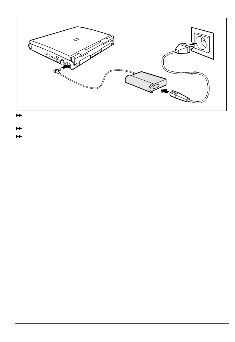
1
2
3
Plug the DC output connector on the power adapter into the DC input connector (DC IN) on the
notebook (1).
Connect the AC power cable to the power adapter (2).
Plug the power cable into the power outlet (3).
The power adapter indicator lights up. The battery charges.
The battery Preparation for use and operation
A26391-K84-Z100-1-7619 25
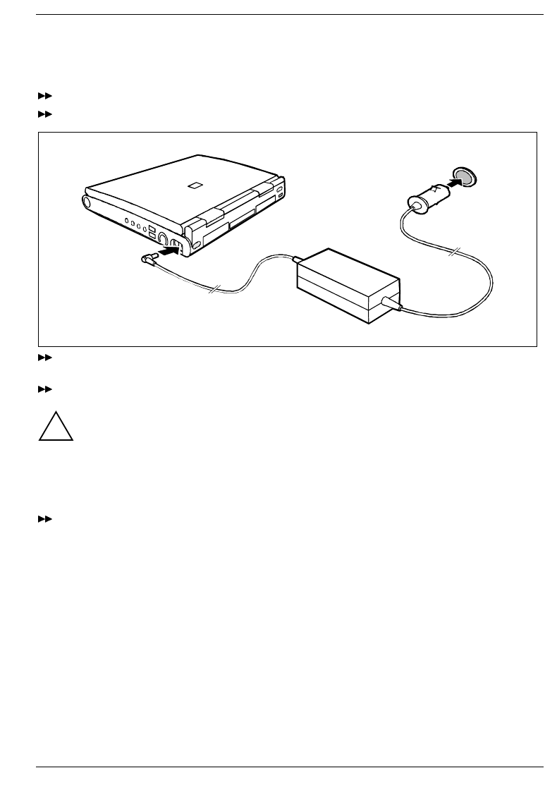
Connecting the car adapter
You can use the car adapter to charge your notebook's battery if the car has a 12V electrical system.
Switch off the notebook.
Place the notebook on a level, stable surface.
1
2
Plug the DC output connector on the car adapter into the DC input connector (DC IN) on the
notebook (1).
Start the car's engine.
!You should only use the car adapter while the car's engine is running. You must not start the
car's engine while the car adapter is connected to the car's electrical system.
Do not stand the car adapter on heat-sensitive material. When in operation, the car adapter
must be free-standing and may not be covered.
Keep other objects 200 mm clear of the notebook. Do not cover the ventilation slots in the
notebook.
Plug the car adapter's input connector into the car's cigarette lighter (2). The battery charges.
Preparation for use and operation The battery
26 A26391-K84-Z100-1-7619
Removing and installing drives and batteries
!Only use batteries designed for the this notebook.
Never use force when inserting or removing a battery.
Make sure that no foreign objects enter the slots.
Drives can only be installed in the right slide-in module.
Batteries can be installed in the left and right slide-in module.
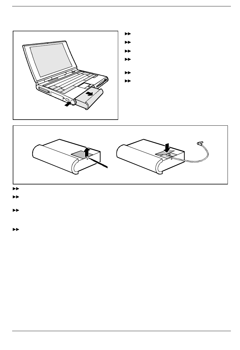
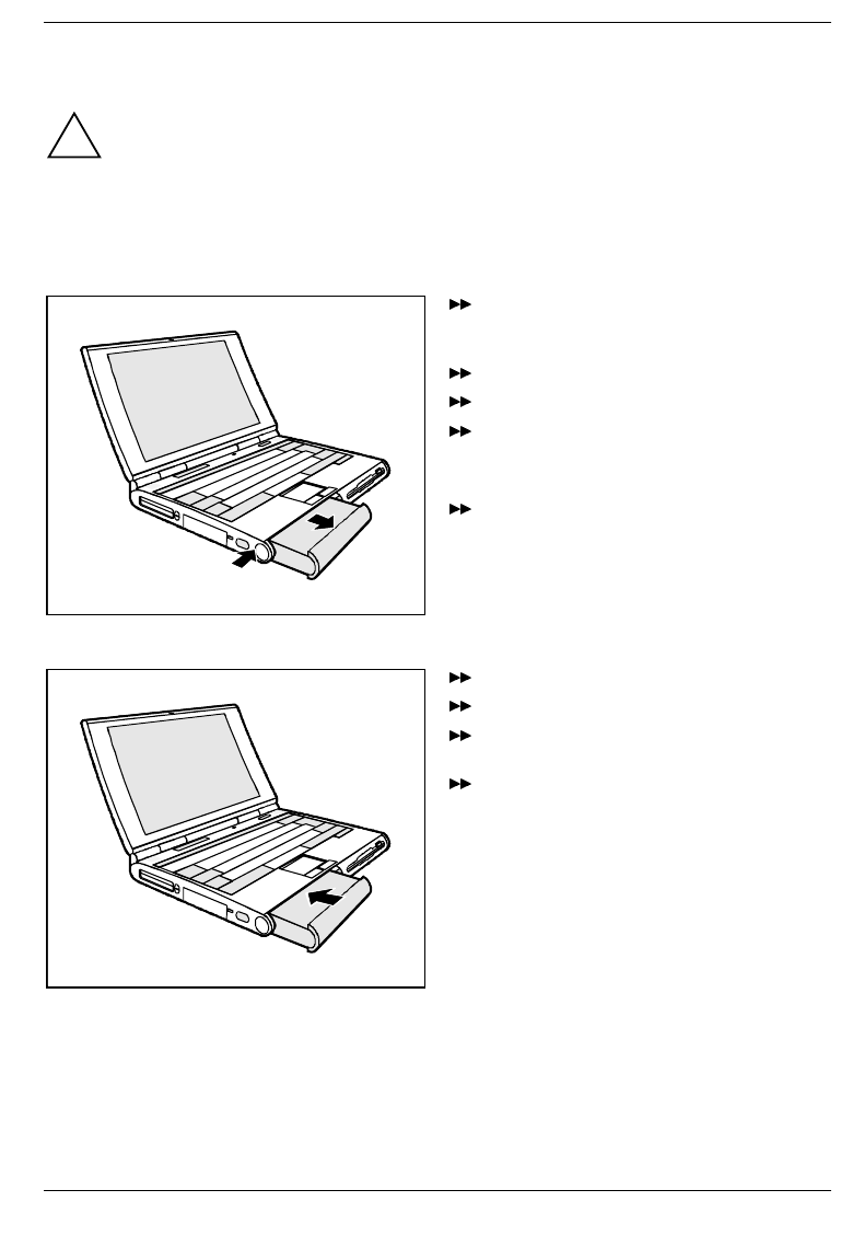
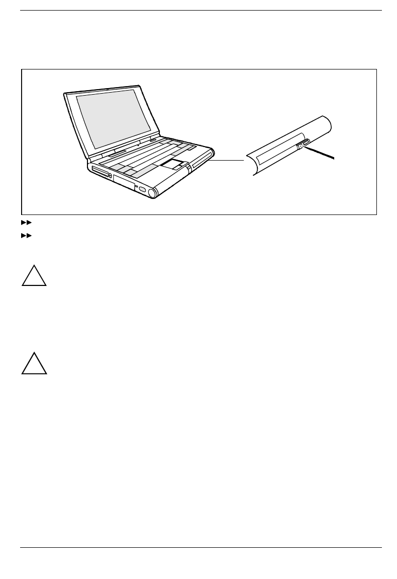
Removing drive/battery
1
2
Switch off the notebook. You can leave the
notebook on provided the battery is not the
notebook’s only power source.
Swing open the display.
Place the notebook on a level surface.
Press the battery’s unlock button (1).
The release button for drives is located on the
right side.
Pull the battery (2) or, on the right side, the
drive out of the slide-in module.
Installing drive/battery
Swing open the display.
Place the notebook on a level surface.
Place the battery in the slot so that the
contacts enter first.
Push the battery into the slot until you feel it
locking into place.
Floppy disk drive Preparation for use and operation
A26391-K84-Z100-1-7619 27
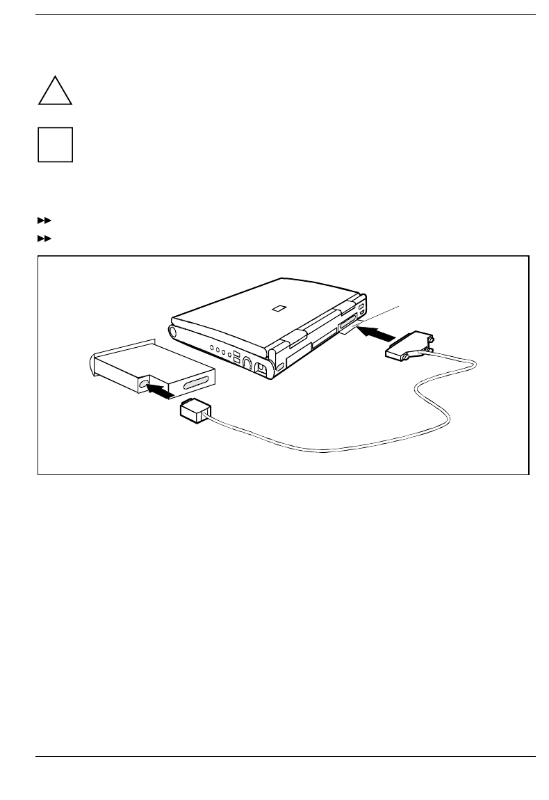
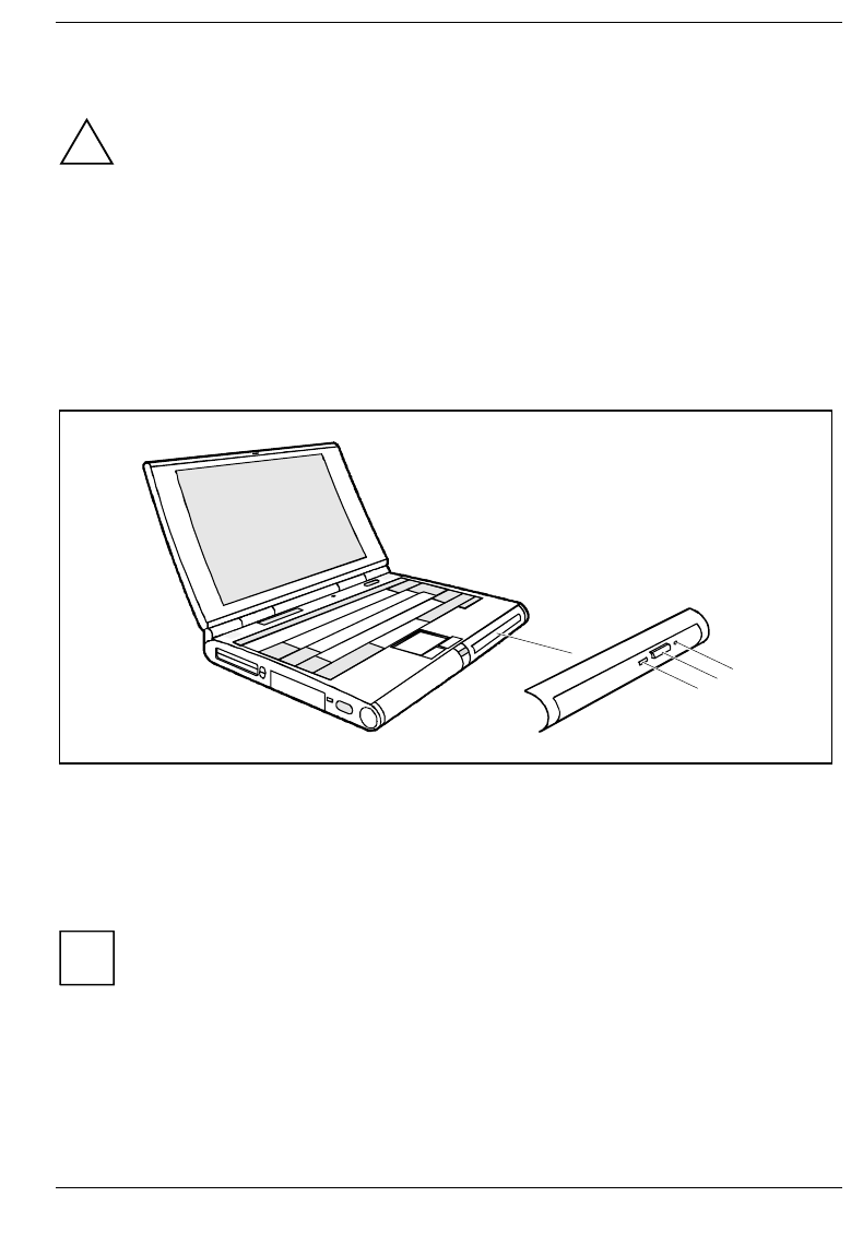
Floppy disk drive
!Use only the floppy disk drive designed for this notebook.
Do not use force when installing or removing the floppy disk drive.
Make sure that no foreign objects enter the slot.
iThe disk drive can also be removed or installed while in operation (but not when the disk
drive is being accessed).
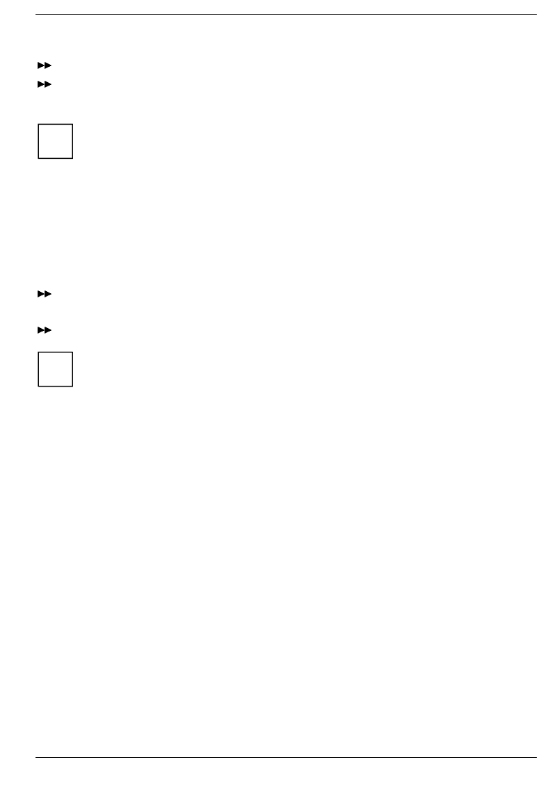
Connecting the floppy disk drive externally
Open the cover (1).
Connect the floppy disk drive externally to the parallel port via an adapter cable.
1
Preparation for use and operation Floppy disk drive
28 A26391-K84-Z100-1-7619
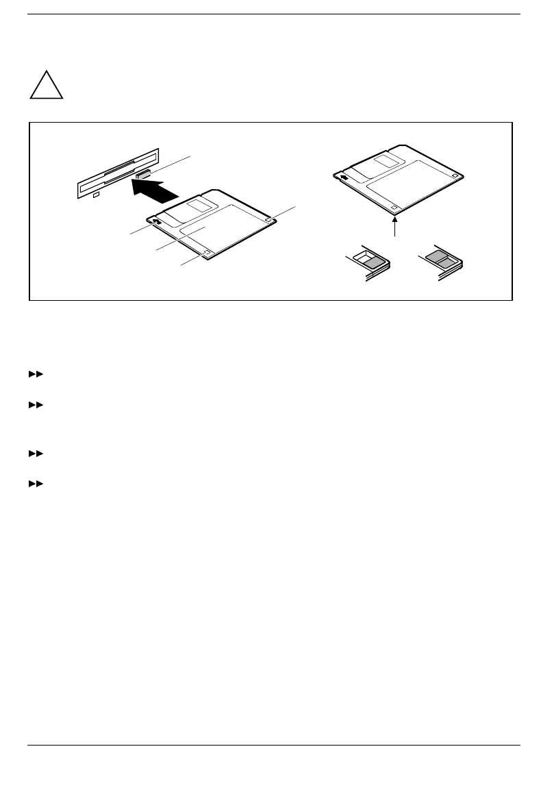
Working with floppy disks
!Follow the instructions supplied by the vendor of the floppy disks.
3
2
1
5
6
4
7
1 = Insertion direction
2 = Label area
3 = Write-protect slider
4 = Hole for recognition of 1.44 Mbytes disk
5 = Eject button for inserted floppy disks
6 = Floppy disk is write protected
7 = Floppy disk is not write-protected
To insert a floppy disk, push it into the drive in the insertion direction (1) until it engages. The label
should be facing upward.
To remove the floppy disk, press the eject button (5).
The write-protect slider enables you to protect the data on the floppy disk from inadvertent overwriting
or deletion.
To protect the data on the floppy disk from being overwritten, push the write-protect slider to
position (6). The hole is now visible.
To remove write protection, push the slider to position (7). The hole is now covered.
Operating the CD-ROM drive and the DVD drive Preparation for use and operation
A26391-K84-Z100-1-7619 29
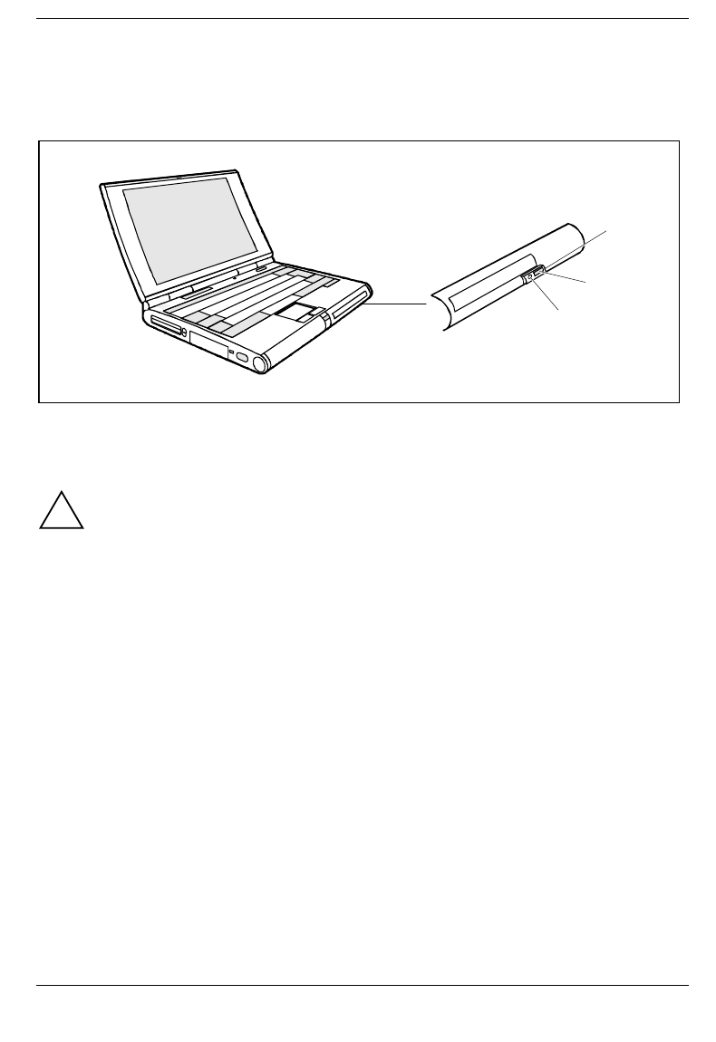
Operating the CD-ROM drive and the DVD drive
!This device contains a light-emitting diode, classified according to IEC 825-1:1993: LASER
CLASS 1 (LUOKAN 1 LASERLAITE, KLASS 1 LASER APPARAT), and must not be
opened.
There is an invisible laser radiation when the cover is open. Avoid exposure to the beam.
Avoid touching the surface of a CD. Handle CDs only by their edges!
Always store CDs/DVDs in their cases. You avoid dust contamination, scratches, bending
or other damage.
Protect your CDs/DVDs from dust, mechanical vibration and direct sunlight!
Avoid storing a CD/DVD in areas subject to high temperatures or humidity.
You may use both 8-cm and 12-cm CDs.
When using CDs/DVDs of minor quality vibrations and reading errors may occur.
3
2
1
1 = Power-on indicator
2 = Insert/Eject button
3 = Opening for manual ejection
Power-on indicator
The power-on indicator (1) flashes when a CD/DVD is inserted. It goes out when the drive is ready for
reading. It lights up when the drive is accessed.
iIf the power-on indicator does not go out after the CD/DVD is inserted, and continues to
flash, the CD/DVD is probably damaged or dirty.
If the inserted CD/DVD vibrates and/or reading errors occur, then it may be possible to
eliminate the vibrations or reading errors by reducing the rotating speed. Press the
Insert/Eject button for roughly two seconds. Reducing the rotating speed also saves power.
Preparation for use and operation Operating the CD-ROM drive and the DVD drive
30 A26391-K84-Z100-1-7619
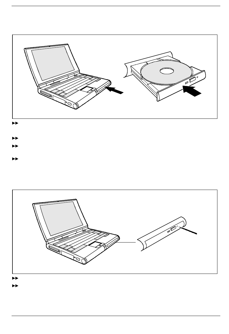
Inserting or removing a CD/DVD
The notebook must be switched on.
Press the Insert/Eject button for roughly one second.
The CD/DVD tray opens.
Pull the CD/DVD tray completely out.
Place the CD/DVD in the CD/DVD tray with the labeled side facing upwards, and carefully push
the CD/DVD into the mount or remove an inserted CD/DVD.
Push the CD/DVD tray in until you feel it locking into place.
Manual removal (emergency removal)
In the event of a power failure or damage to the drive it may be necessary to manually remove the
CD/DVD.
Switch off the notebook.
Press a piece of wire (e. g. a paper clip) firmly into the opening.
The CD/DVD tray is unlocked. You can now pull it out of the drive.

Operating the Zip drive Preparation for use and operation
A26391-K84-Z100-1-7619 31
Operating the Zip drive
Before the Zip drive can be used, you must install the Iomega software on your notebook. To do this,
use the Iomega installation disk provided and the Zip disk "Iomega Tools".
Installing the Iomega software
Install the Zip drive in the right slide-in module.
Connect the floppy disk drive to the parallel port (see "Connecting the floppy disk drive
externally".
Supply the notebook with power via the power adapter.
Switch on the notebook and start Windows.
Insert the Iomega installation floppy disk in the floppy disk drive.
Start the a:\setup.exe program from the Iomega installation disk with Start - Run (Windows 9x) or
File - Run (Windows 3.1).
Follow the instructions on the screen.
Switch on the notebook again and start Windows.
Insert the Zip disk "Iomega Tools" in the Zip drive.
Follow the installation instructions displayed on the screen to finish the software installation.
Reinstalling the Iomega software from the Zip disk
If the Zip drive of your notebook has already been assigned a drive letter in My Computer or in the File
Manager, you can install the Iomega software directly from the Zip disk "Iomega Tools".
Install the Zip drive.
Switch on your notebook and start Windows.
Insert the Zip disk "Iomega Tools" in the Zip drive.
Open a search window for the Zip disk "Iomega Tools" with My Computer (Windows 9x).
Double-click on INSTALL.EXE.
Follow the installation instructions displayed on the screen to finish the software installation.
Preparation for use and operation Operating the Zip drive
32 A26391-K84-Z100-1-7619
Operation
Use the Zip drive like any other drive on your system. To be able to access the Zip drive, you must
insert a disk and click on the Zip disk symbol or the Zip drive letter. Save and copy the files on the Zip
drive with the same method used for other drives on your system.
1
2
3
1 = Eject button
2 = Drive indicator
3 = Opening for manual ejection
Handling Zip disks
!Follow the instructions supplied by the vendor of the Zip disks and the following notes:
Always switch your computer on before inserting a Zip disk.
Never use force when inserting and removing Zip disks.
Never use ordinary 3.5" disks or cleaning disks in your Zip drive. This will damage the Zip
drive.
Do not move the protection against accidental contact on the Zip disk.
Protect your Zip disk from dust, mechanical vibration, heat, direct sunlight and strong
magnetic fields!
Do not drop the Zip disk.
Do not use the Zip disk during large fluctuations in temperature or humidity.
Always transport the Zip disk in its protective cover.
Never clean the Zip drive with cleaning disks. Even just one attempt would destroy the
read/write head in the Zip drive within 20 seconds.
Operating the Zip drive Preparation for use and operation
A26391-K84-Z100-1-7619 33
Inserting the Zip disk
Switch on your notebook.
Insert the Zip disk in the Zip drive.
The green drive indicator glows briefly and then goes out again.
iShould the indicator continue to flash slowly, please press the eject button to remove the
Zip disk and then insert it again.
Sleep mode of drive
The Zip drive is equipped with an automatic sleep mode. This is intended to reduce the power
consumption, and thus to extend the operating time of the battery. In the sleep mode the speed of the
disk is automatically reduced after an adjustable, inactive time (e.g. 3 minutes). If the drive is
accessed, the speed of the disk is automatically increased again. The sleep mode time for the Zip drive
is controlled via the system settings of your notebook.
Removing the Zip disk
Gently push the eject button.
The green drive indicator lights up. After a few seconds the Zip disk is then ejected.
Please lay the Zip disk in the protective case after removing it from the drive.
iWhen the notebook is switched off, the Zip drive automatically ejects the Zip disk.
Preparation for use and operation PC Cards
34 A26391-K84-Z100-1-7619
Manual removal (emergency removal)
For normal removal of Zip disks, the notebook must be switched on. If the power supply of the
notebook is interrupted, the Zip disk can be removed manually.
Switch off the notebook.
Press a piece of wire (e. g. a paper clip) firmly into the opening.
The Zip disk is unlocked. You can now pull it out of the drive.
!Only use the disk emergency removal function when no battery is installed in the notebook
and no power supply unit is connected to the notebook.
PC Cards
Two PC card slots (CardBus or PCMCIA) enable the notebook to operate two type II PC cards or one
type III PC card.
!
The PC card must not consume more than 600mA (at +5V) or 60mA (at +12V).
Consult the documentation supplied by the PC card's manufacturer and follow the
instructions provided.
Never use force when inserting or removing a PC card.
Make sure that foreign objects do not fall into the PC cards slot.
Zoomed video port
Your notebook is equipped with a Zoomed video port (ZV port). You can install an MPEG decoder or a
TV and frame grabber card in a PC Card slot. Please contact one of your IT service partners, your
local sales partner or office for advice on selecting a suitable ZV port card.
PC Cards Preparation for use and operation
A26391-K84-Z100-1-7619 35
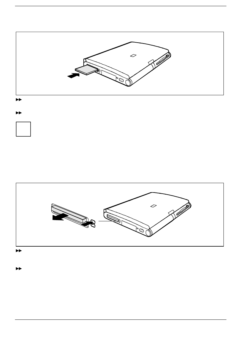
Installing a PC card
Insert the PC card, contacts first, into the slot guides. The labeled side of the PC card must be
facing upwards.
Gently push the PC card into the slot until you feel it click into place.
iConsult the documentation supplied with the PC card for information on how to install the
necessary device drivers.
For further information refer to the information files (e.g. *.TXT, *.DOC, *.WRI, or *.HLP)
provided with the PC card driver diskette or the information in the Windows 9x manual.
You can push the PC card slot eject buttons down flush into the notebook casing. Press the
eject buttons until they snap in.
Removing PC cards
1
2
Press the eject button (1). It will project further out of the notebook's case. If the eject buttons are
pushed in flush with the notebook casing, they must first be snapped out. Press the eject buttons
until they snap out.
Slide the PC card out of the notebook (2).
Preparation for use and operation Microphone and loudspeaker
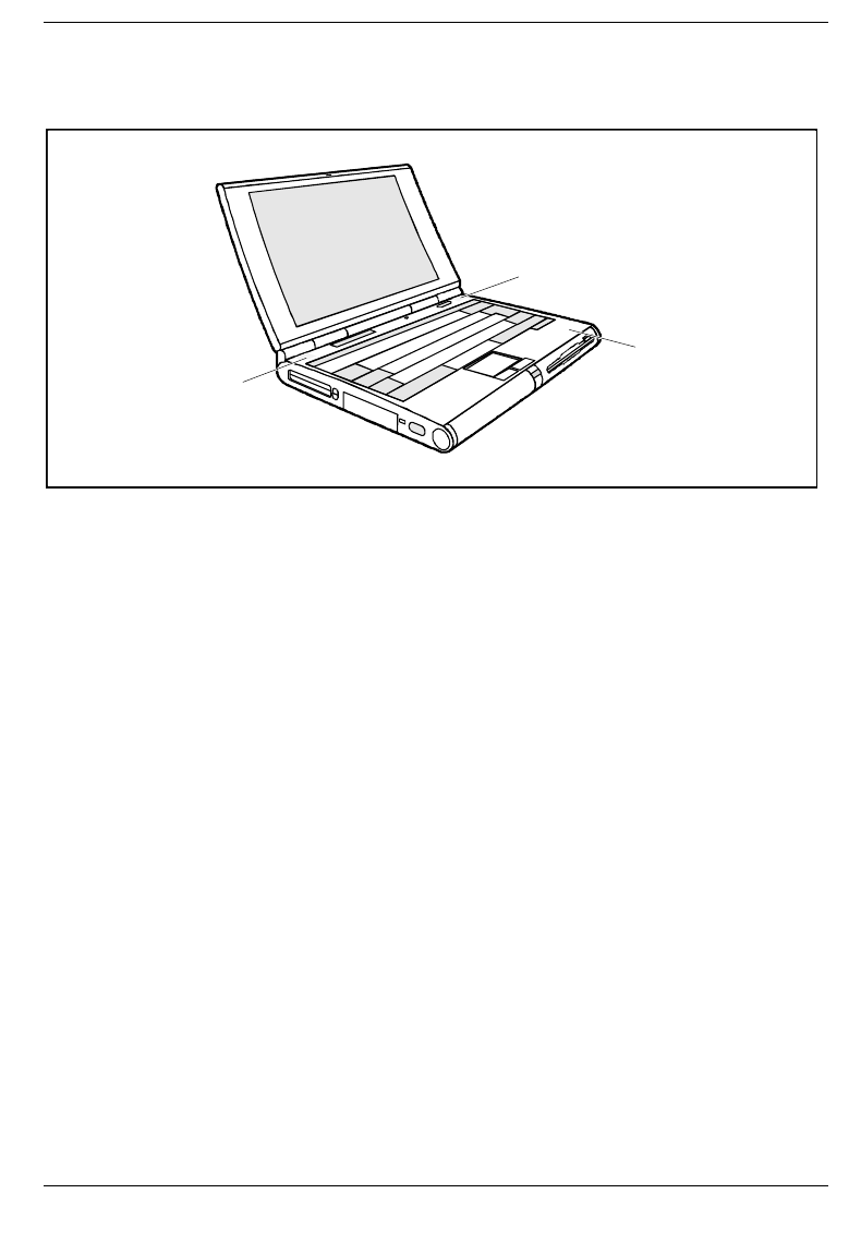
36 A26391-K84-Z100-1-7619
Microphone and loudspeaker
1
2
2
1 = built-in microphone 2 = built-in loudspeaker
Your notebook contains a built-in microphone (1) and a loudspeaker (2).
If you attach an external microphone, the built-in microphone is disabled. If you attach an external
loudspeaker, the built-in loudspeaker is disabled.

Using the power-management features Preparation for use and operation
A26391-K84-Z100-1-7619 37
Using the power-management features
The notebook uses less power when the power management features are enabled. You will then be
able to work for longer before having to recharge the battery.
If you will not be using your notebook for a longer period, switch it off.
Reducing the brightness level of the display helps to reduce the amount of power consumed by the
notebook.
iIf you enable one of the power-management options in the Power menu of the BIOS Setup,
that option will still be enabled the next time you switch on your notebook.
Maximum Battery Life-Mode
The Maximum Battery Life mode uses all the available power-management features. The notebook
uses little power and operates slightly slower than usual.
Activating
In the Power Setup menu set the Power Savings field to Maximum Battery Life.
Set the PM Control field in the Power Setup menu to Always Enable or to Battery Powered Only.
Exit
In the Power Setup menu set the PM Control field to Disabled.
Standby mode
In Standby mode the notebook's system clock is suspended and its display and hard-disk motor are
shut down.
Activating
Press the key combination + .
Exit
Press any key to continue.
Automatic activation
If the notebook is running and is not used for a predefined period of time, it switches into Standby
mode. Any input causes the notebook to come out of Standby mode.
In the Power Setup menu set the Power Savings field to Customize and set the time which has to
elapse before the notebook switches to Standby mode in the Standby Timeout field.
or
In the Power Setup menu set the Power Savings field to Maximum Performance or
Maximum Battery Life.

Preparation for use and operation Using the power-management features
38 A26391-K84-Z100-1-7619
Suspend mode
In suspend mode, all current data (active programs, files) is saved to the hard disk or buffered in the
memory, and the notebook is switched off.
Suspend to Disk
The active data can only be saved if sufficient space is available on the hard disk (at least the main
memory size + 2 Mbytes). If the operating system Windows NT or OS/2 Warp is used, a FAT partition
with this space must be created as a drive on the hard disk (see manual for respective operating
system).
Suspend to DRAM
The current data is buffered in the memory (DRAM). The data is stored for as long as the notebook is
supplied with energy. If the battery is full, the data is stored for a matter of days. Without a battery and
without a power supply the data is stored for only around 5 minutes. Without a battery and without a
power supply the current data is lost.
Activating
!If your notebook is in Suspend mode:
• do not connect any external peripheral devices
• do not disconnect any external peripheral devices
• do not attempt to switch it on if the built-in battery is empty
• do not change or remove the floppy disk, if inserted
• do not add or remove RAM
do not add or remove any PC cards.
Press the key combination + .
or Hold the on/off switch pressed for approximately one second.
Exit
Switch on the notebook.
The notebook reverts to the status it had prior to switching into Suspend mode.
Automatic activation
If the notebook is running and is not used for a predefined period of time, it switches into Suspend
mode.
In the Power Setup menu set the Power Savings field to Customize and set the time which has to
elapse before the notebook switches to Standby mode in the Suspend Timeout field.
Set the Suspend Mode field to Save to Disk or Save to DRAM.
or In the Power Setup menu set the Power Savings field to Maximum Performance or
Maximum Battery Life.
Set the Suspend Mode field to Save to Disk or Save to DRAM.

Using the power-management features Preparation for use and operation
A26391-K84-Z100-1-7619 39
Display
Switching off the display does not affect running programs.
Activating
Press any key to continue.
Deactivating
Press the key combination + .
Automatic powerdown
You set this function in the BIOS Setup.
If the notebook receives no input for a predefined period of time, the display switches off automatically.
It switches on again automatically as soon as the notebook receives input.
In the Power Setup menu set the Power Savings field to Customize and set the time which has to
elapse before the display switches off in the Video Timeout field.
or
In the Power Setup menu set the Power Savings field to Maximum Performance or
Maximum Battery Life.
Hard disk's power-management feature
If the hard disk is not accessed for a predefined period of time, its motor switches off automatically. It
switches on again automatically the next time the hard disk is accessed.
Activating
In the Power Setup menu set the Power Savings field to Customize and set the time which has to
elapse before the motor of the hard disk switches off in the Hard Disk Timeout field.
or
In the Power Setup menu set the Power Savings field to Maximum Performance or
Maximum Battery Life.
Loudspeaker
Deactivating
Press the key combination + .
Activating
Press the key combination + .
Deactivating in BIOS Setup
In the Advanced Setup Integrated Peripherals menu set the On Board Audio field to Disabled.

Preparation for use and operation Volume adjustment
40 A26391-K84-Z100-1-7619
Volume adjustment
Increasing the volume
Press the key combination + .
Reducing the volume
Press the key combination + .
You can also adjust the volume of the loudspeaker in the audio program (e.g. mixer) or in the
application program using the audio functions.
Changing display settings
You configure the basic display settings in the Main Setup (see chapter "Settings in BIOS Setup").
You can change the settings using key combinations.
Switching between internal and external display
If an external monitor is connected to your notebook, you can switch between different display options.
You can opt to use:
• just the notebook's internal display
• just the external display
• both the internal and the external display
• just the television
• both the internal display and the television.
The setting you select with Display Device Selection in Main Setup is always active when you switch on
your notebook.
Press the key combination + until you find the display option you require.
Starting BIOS Setup BIOS Setup
A26391-K84-Z100-1-7619 41
Settings in BIOS Setup
In BIOS Setup you can set the system functions and the hardware configuration of the notebook.
When it is supplied, the notebook is set to factory default settings. You can change these settings in
BIOS Setup. Any changes you make take effect as soon as you save and quit the BIOS Setup.
The BIOS Setup program contains the following menus:
• Main Setup: for system settings as time, date, ports and pointing device
• Advanced Setup: for extended functions
• Security Setup: for setting up the security features
• Power Setup: for setting up the power-management features
• Docking Setup: for configuring the MobiDock
• Boot Setup: for configuring the boot sequence
• Exit: Exiting BIOS Setup
Starting BIOS Setup
Restart the notebook (switching on/off or warm boot).
When the message Press F2 for Setup appears, press the key .
iIf a supervisor or user password has been defined:
Enter the supervisor or user password and press the Enter key.
If you have forgotten the user password contact your system administrator or contact
our customer service. If you have forgotten the supervisor password contact our
customer service.
If access to the setup is obtained with the user password, BIOS Setup settings in the Advanced, Security,
Docking and Boot menus are not possible.
BIOS Setup Operating BIOS Setup
42 A26391-K84-Z100-1-7619
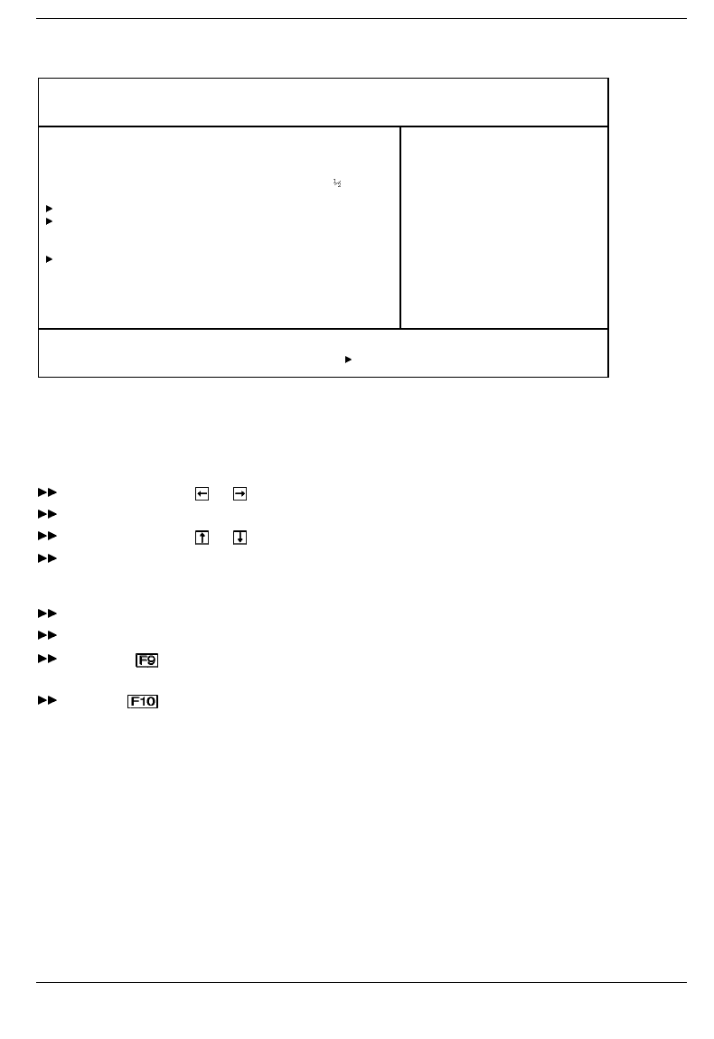
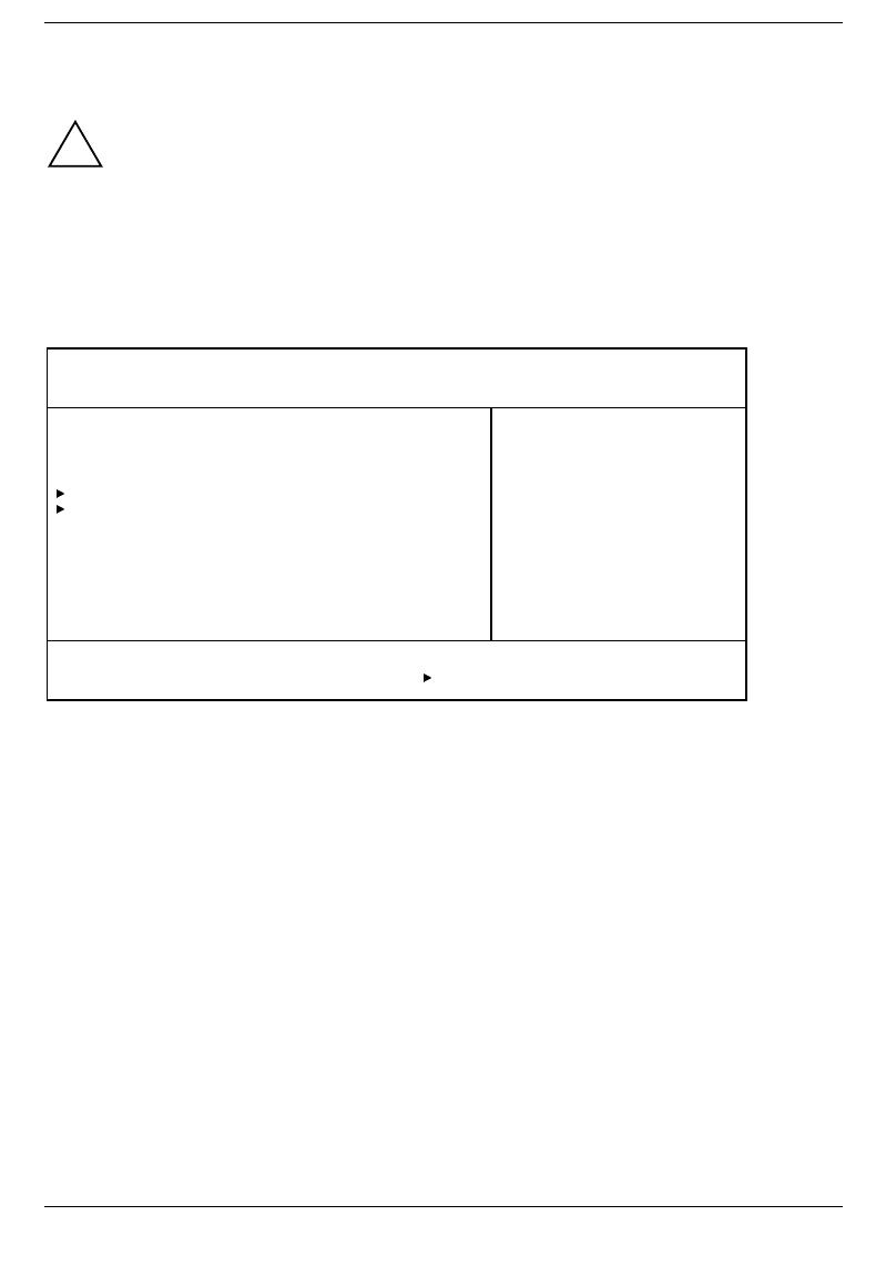
The Main menu is displayed on the screen.
Phoenix BIOS Setup
Main Advanced Security Power Docking Boot Exit
System Time: [08:00:00]
System Date: [12/12/1997]
Diskette A: [1.44M, 3 ]
IDE Adapter 0 Master (C: 810 MB)
IDE Adapter 1 Master [None]
Display Device Selection: [LCD & CRT]
TV Mode: [PAL]
Boot Options
System Memory: 640 KB
Extended Memory: 15 MB
Item Specific Help
——————————————————————
F1 Help ↑↓ Select Item Space Change Values F9 Setup Defaults
ESC Exit ← → Select Menu Enter Select Sub-Menu F10 Previous Values
Example for Main menu
Operating BIOS Setup
Use the cursor key or to select the menu you wish to access to make changes.
Press the Enter key. The menu is displayed on the screen.
Use the cursor key or to select the field you wish to change.
Press the Space key to change the value of an entry.
You must enter characters in the Supervisor Password, User Password and Docking Station
Password fields.
Repeat the last two steps described for all the fields you wish to change.
Make a note of the changes you have made (here in this manual, for example).
Using the function key, you can load the default settings for the Setup menu you are currently
in.
With the key all the values of the menu you are currently in are restored.
Main menu - Making system settings BIOS Setup
A26391-K84-Z100-1-7619 43
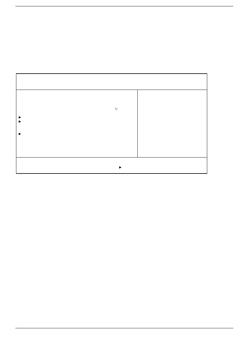
Main menu - Making system settings
In the Main menu you can set up the following:
• time (in the field marked Time)
• date (in the field marked Date)
• hard disk settings (in the two fields marked IDE Adapter)
• display device (in the field marked Display Device Selection)
• Pointing elements (in the field marked PS/2 Pointing Device)
• System startup options (in the field marked Boot Options)
Phoenix BIOS Setup
Main Advanced Security Power Docking Boot Exit
System Time: [08:00:00]
System Date: [08/14/1998]
Diskette A: [1.44M, 3 ]
IDE Adapter 0 Master (C: 810 MB)
IDE Adapter 1 Master [None]
Display Device Selection: [LCD & CRT]
TV Mode: [PAL]
Boot Options
System Memory: 640 KB
Extended Memory: 15 MB
Item Specific Help
——————————————————————
F1 Help ↑↓ Select Item Space Change Values F9 Setup Defaults
ESC Exit ← → Select Menu Enter Select Sub-Menu F10 Previous Values
Example for Main menu
System Time/System Date
System Time indicate the time of the device. If you change the time setting, enter the time in the
format HH:MM:SS (hours:minutes:seconds)
System Date indicate the date of the device. If you change the date setting, enter the date in the
format MM.DD.YYYY (month/day/ year)
Diskette A: - floppy disk drive
This field shows the type of the built-in floppy disk drive.
360KB - 5 1/4", 720KB - 3 1/2", 1.2MB- 51/4", 1.44MB - 3 1/2", 2.88MB - 3 1/2"
The entry depends on the floppy disk drive installed.
Not Installed A floppy disk drive is not installed.
BIOS Setup Main menu - Making system settings
44 A26391-K84-Z100-1-7619
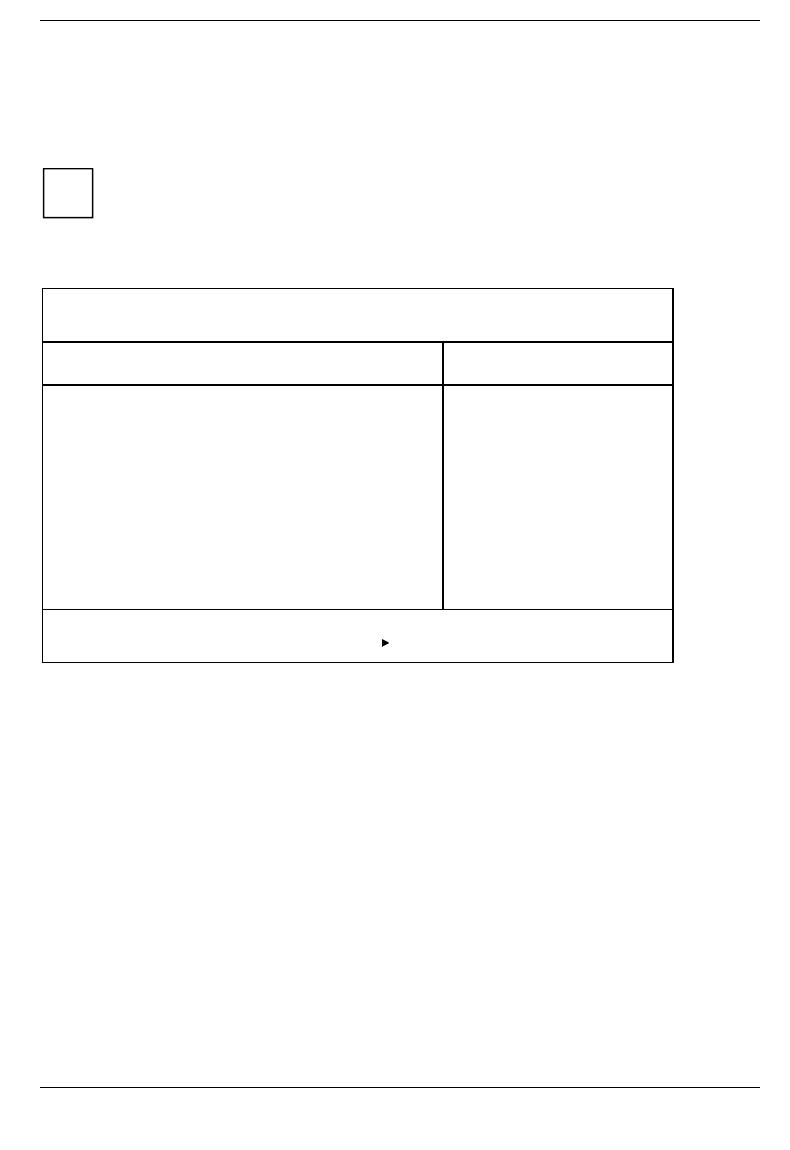
IDE Adapter 0 Master/IDE Adapter 1 Master -
hard disk drive
These two fields call the submenu to make corresponding settings of the IDE hard disk drives.
iYou should change the default settings only if you are connecting an additional IDE drive
(e.g. CD ROM drive)
The following description of the setting options for IDE Adapter 0 Master also applies to IDE Adapter 0
Slave, IDE Adapter 1 Master and IDE Adapter 1 Slave. The default settings depend on the installed drive.
Phoenix BIOS Setup
Main
IDE Adapter 0 Master (C: 814 MB) Item Specific Help
Type Fixed Disk: [Press Enter]
Type: [Auto] 814 Mb
Cylinders: 1579
Heads: 16
Sectors: 63
Maximum Capacity:
Multi-Sector Transfers: 16 Sectors
LBA Mode Control: Enabled
32 Bit I/O: [Enabled]
Transfer Mode: Fast PIO 3
Ultra DMA Mode: [Disabled]
F1 Help ↑↓ Select Item Space Change Values F9 Setup Defaults
ESC Exit ← → Select Menu Enter Select Sub-Menu F10 Previous Values
Example for the submenu IDE Adapter 0 Master
If you have installed a new unformatted IDE hard disk drive, you should mark the Type Fixed Disk field
and press the Enter key. This has the effect of setting the optimum values for the IDE hard disk drive.
You can change these values if you set the Type field to User.
If you install a formatted hard disk drive, the values are set automatically.

Main menu - Making system settings BIOS Setup
A26391-K84-Z100-1-7619 45
Type - Hard Disk Type
This field is used to specify the type of hard disk drive.
Auto If the hard disk supports this mode, the setup menu reads the hard disk parameters
from the disk itself. You do not need to select the parameters yourself.
User You can enter the hard disk parameters yourself.
If you have set the hard disk parameters with Autotype Fixed Disk, you can only reduce
the values.
None You cannot change the hard disk parameters (Cylinders, Heads, Sector/Track and Write
Precomp.). An IDE drive has not been installed.
CD If, for example, a CD-ROM drive is inserted into the notebook, or a CD-ROM drive is
built into the MobiDock, this item enables you to boot the system from the CD-ROM
drive.
Cylinders, Heads, Sectors/Track, Write Precomp - hard disk parameter
These hard disk parameters are set in accordance with the IDE hard disk drive. If you want to change
the hard disk parameters manually, set the Type field to User.
Multi-Sector Transfers - Block Transfer
This field specifies the transfer mode for the IDE hard disk drive.
Disabled One block is transferred for each interrupt.
2 Sectors, 4 Sectors, 6 Sectors, 8 Sectors, 16 Sectors
The set number of blocks (sectors) is transferred for each interrupt. This enhances
performance.
LBA Mode Control - Addressing
This field enables and disables the LBA (Logical Block Addressing) mode. If a hard disk supports LBA
mode, the LBA mode allows you to set up and use hard disks with a capacity of more than 528 Mbytes.
The default entry depends on the installed IDE hard disk drive. Change the default entries only if you
are installing another hard disk drive.
!You may only use IDE drives in the LBA mode selected when they were set up. In other
words, if you set up a hard disk with LBA mode disabled, you may only operate the hard disk
with LBA mode disabled.
Disabled The BIOS uses the hard disk parameters and supports a maximum capacity of 528
Mbytes.
Enabled If the hard disk supports LBA and it has a capacity of more than 528 Mbytes, the BIOS
translates the hard disk parameters, allowing the disk's full capacity to be used. This
allows the disk's full capacity to be used.

BIOS Setup Main menu - Making system settings
46 A26391-K84-Z100-1-7619
32 Bit I/O - Access width for data transfer
This field specifies the I/O access width of data transmission between the processor and the IDE
controller.
Enabled Data transfer is performed with 32-bit I/O commands. This enhances performance.
Disabled Data transfer is performed with 16-bit I/O commands.
Transfer Mode
This field specifies the transfer mode for the IDE hard disk drive.
Standard 0,8 Mbytes/s to 2 Mbytes/s
Fast PIO 1 2 Mbytes/s to 4 Mbytes/s
Fast PIO 2 4 Mbytes/s to 5 Mbytes/s
Fast PIO 3 5 Mbytes/s to 10 Mbytes/s
Fast PIO 4 10 Mbytes/s to 13.3 Mbytes/s
Ultra DMA Mode - Access Speed
This field specifies the access speed for the IDE hard disk drive.
Mode 0 slow access speed
Mode 1 middle access speed
Mode 2 fast access speed
Display Device Selection
This field is used to specify the display device.
LCD&CRT The notebook's internal display and the external display are used.
CRT Just the external display is used.
LCD Just the internal display is used.
TV
Output is carried out on the TV.
LCD & TV The notebook's internal display and the television are used.
If the notebook is connected to a MobiDock and an external display is connected to the MobiDock, the
external display is used regardless of the setting in the BIOS Setup (CRT only).
TV Mode
This field is used to specify the display device.
PAL Output on the TV is in the PAL standard.
NTSC Output on the TV is in the NTSC standard.

Main menu - Making system settings BIOS Setup
A26391-K84-Z100-1-7619 47
Boot Options - System startup options
This field calls the submenu to select the settings for the system startup of the device.
Phoenix BIOS Setup
Main
Boot Options Item Specific Help
Summary screen: [Enabled]
Floppy check: [Disabled]
Quiet Boot: [Enabled]
F1 Help ↑↓ Select Item Space Change Values F9 Setup Defaults
ESC Exit ← → Select Menu Enter Select Sub-Menu F10 Previous Values
Example for submenu Boot Options
Summary screen - Displaying the configuration at system startup
This field is used to specify whether the configuration is displayed at system startup.
Enabled The configuration is displayed when the device is switched on.
Disabled The configuration is not displayed when the device is switched on.
Floppy check - Checking the disk drive
This field can make the system startup faster.
Enabled The entire notebook configuration is checked when the notebook is switched on.
Disabled The disk drive is not checked in the self-test when the device is switched on.
Quiet Boot
Instead of a start information a logo is displayed on the screen.
Enabled The logo is displayed on the screen. A switch to the start information is made if you
press the key or if errors occur.
Disabled The start information is displayed on the screen.
System Memory - Main memory
This field indicates the size of the available base memory below 1 Mbyte.
Extended Memory
This field indicates the size of the memory above 1 Mbyte.
BIOS Setup Advanced menu - Advanced system settings
48 A26391-K84-Z100-1-7619
Advanced menu - Advanced system settings
!Change the default settings only for special applications. Incorrect settings can cause
malfunctions.
You can make the following system settings in the Advanced menu:
• Ports and controllers (in the Integrated Peripherals submenu)
• PCI configuration ( in the PCI Devices submenu)
• Second-level cache (in the Memory Cache submenu)
• Plug&Play functionality (in the Plug and Play O/S field)
• Configuration data (in the Reset Configuration Data field)
• Hard disk access (in the Large Disk Access Mode field)
Phoenix BIOS Setup
Main Advanced Security Power Docking Boot Exit
Warning!
Setting items on this menu to incorrect values
may cause your system to malfunction.
Integrated Peripherals
PCI Devices
Plug & Play O/S: [Yes]
Enable ACPI [No]
Reset Configuration Data: [No]
Large Disk Access Mode: [DOS]
Item Specific Help
——————————————————————
F1 Help ↑↓ Select Item Space Change Values F9 Setup Defaults
ESC Exit ← → Select Menu Enter Select Sub-Menu F10 Previous Values
Example for the Advanced menu

Advanced menu - Advanced system settings BIOS Setup
A26391-K84-Z100-1-7619 49
Integrated Peripherals - Ports and controllers
This field calls the submenu to make the settings for the ports and controllers.
Phoenix BIOS Setup
Advanced
Integrated Peripherals Item Specific Help
PS/2 Mouse [Auto Detect]
COM port: [Enabled]
Base I/O Address: [3F8 IRQ4]
IrDA port: [Auto]
Mode: [IrDA]
Parallel port [Auto]
Mode: [Bi-Directional]
Diskette Controller: [Enabled]
On board IDE Adapter: [Both]
On Board Audio: [Auto]
Base I/O Address: [220]
IRQ Channel: [IRQ 5]
Capture DMA channel: [DMA 1]
Playback DMA channel: [DMA 3]
FM I/O: [388]
MPU I/O: [300]
Joystick: [Enabled]
FM I/O: [201]
QuickPort Audio
Speaker: [Notebook]
Microphone: [Notebook]
F1 Help ↑↓ Select Item Space Change Values F9 Setup Defaults
ESC Exit ← → Select Menu Enter Select Sub-Menu F10 Previous Values
Example for the submenu Integrated Peripherals
PS/2 Mouse
This field determines whether the PS/2 mouse or the touchpad is enabled on the notebook.
Enabled The internal touchpad is activated if no PS/2 mouse is connected. If a PS/2 mouse is
connected when the system is started up, the PS/2 mouse is activated and the internal
touchpad is deactivated.
Disabled The internal touchpad and the PS/2 mouse are disabled.
You must set Disabled if you want to use an external serial mouse.
Auto Detect The internal touchpad is activated if no PS/2 mouse is connected. If a PS/2 mouse is
connected when the system is started up, the PS/2 mouse is activated automatically
and the internal touchpad is deactivated.

BIOS Setup Advanced menu - Advanced system settings
50 A26391-K84-Z100-1-7619
COM port - Serial port
This field switches the serial port on or off.
Enabled The serial port can be set to a certain address and interrupt in the Base I/O Address field.
Auto The serial port is automatically set to the next available combination (address,
interrupt).
Disabled The serial port is disabled.
Base I/O Base Address - Address of the serial port
iThis field is only visible when the Com Port field is set to enabled.
This field selects the address and the interrupt used to access the relevant serial interface.
3F8h IRQ4, 2F8h IRQ3, 3E8h IRQ4, 2E8h IRQ3, 3F8h IRQ5, 2F8h IRQ7, 3E8h IRQ5, 2E8h IRQ7
The serial port is set to the shown address and interrupt.
IrDA port - Infrared interface
This field switches the infrared interface on or off.
If you wish to use infrared data transfer, an infrared interface with the associated hardware must be
incorporated in the device.
Enabled The infrared interface can be set to a certain address and interrupt in the Base I/O
Address field.
Auto The infrared interface is automatically set to the next available combination (address,
interrupt).
Disabled The infrared interface is disabled.
Base I/O Address - Address of the infrared interface
iThis field is only visible when the IrDA Port field is set to Enabled.
This field selects the address and the interrupt used to access the relevant IrDA interface.
3F8h IRQ4, 2F8h IRQ3, 3E8h IRQ4, 2E8h IRQ3, 3F8h IRQ5, 2F8h IRQ7, 3E8h IRQ5, 2E8h IRQ7
The IrDA interface is set to the shown address and interrupt.

Advanced menu - Advanced system settings BIOS Setup
A26391-K84-Z100-1-7619 51
Mode - Infrared Interface Mode
This field sets the mode for the infrared interface.
IrDA Standard IrDA is set.
Ask-IR A data transfer rate of 38,4 kbit/s is set.
FIR Fast IrDA is set.
Parallel port
This field selects the address and the interrupt used to access the relevant parallel port.
Enabled The parallel port can be set to a certain address and interrupt in the Base I/O Address
field.
Auto The parallel port is automatically set to the next available combination (address,
interrupt).
Disabled The parallel port is disabled.
Base I/O Address - Address of the parallel port
iThis field is only visible when the Parallel Port field is set to enabled.
This field selects the address and the interrupt used to access the relevant parallel interface.
378h IRQ7, 278h IRQ5, 3BCh IRQ7, 378h IRQ5
The parallel port is set to the shown address and interrupt.
Mode - parallel data transmission mode
This field is used to specify whether the parallel interface is to be used as a bi-directional input/output
port or just as an output port. ECP and EPP transfer modes allow faster transfer rates of 2 and
2.4 Mbytes/s. These modes will only work with peripheral devices which support them. In addition, the
field Parallel must be set to 378h or 278h.
Bi-Directional Data can be transferred in both directions across the port.
EPP Fast transfer mode (up to 2 Mbytes/s), can output and receive data. The mode requires
a peripheral device which supports the EPP (Enhanced Parallel Port) transfer mode.
ECP Fast transfer mode (up to 2.4 Mbytes/s), can output and receive data. The mode
requires a peripheral device which supports the ECP (Enhanced Capability Port)
transfer mode.
Output Only Bi-Directional
The port functions as an output port only.
Diskette Controller
This field is used to enable and disable the built-in floppy disk controller on the system board.
Enabled The floppy disk controller is enabled - IRQ 6 is used.
Disabled The floppy disk controller is disabled - IRQ 6 is free.

BIOS Setup Advanced menu - Advanced system settings
52 A26391-K84-Z100-1-7619
On-board IDE Adapter - IDE hard disk controller
This field is used to enable and disable the built-in IDE hard disk drive controller of the notebook.
Both The drives in the notebook are operated via the primary and secondary IDE channel.
IRQ14 and IRQ15 are occupied. The hard disk is operated on the primary IDE channel,
the CD-ROM drive on the secondary IDE channel.
Auto If the notebook is connected to a MobiDock, the hard disk in the notebook is operated
on the primary IDE channel, and the IDE drives in the MobiDock on the secondary IDE
channel. The CD-ROM drive in the notebook is switched off. IRQ14 and IRQ15 are
occupied. If Auto is set, the notebook can only be connected to a MobiDock while
switched off (cold docking). It is not possible to connect the notebook during operation
(hot docking) or while a drive is being accessed (warm docking).
If the notebook is not connected to a MobiDock, Auto corresponds to the entry Both.
Primary The primary IDE hard disk drive controller is enabled. IRQ14 is occupied.
Disabled The IDE hard disk drive controller of the notebook is disabled.
On Board Audio - Audio Controller
This field is used to enable and disable the built-in audio controller on the system board.
Auto The chip is enabled and the configuration is automatically carried out.
Enabled The chip is enabled
Disabled The chip is disabled
iThe following fields are only visible if the On Board Audio field is set to Enabled.
Base I/O Address
The I/O channel can be set to various basic addresses.
220h, 240h, 260h, 280h
The I/O channel is set to the address displayed.
IRQ Channel - Interrupt channel
This field is used to specify the interrupt for the audio controller. The interrupt can be set to various
IRQs.
IRQ5, IRQ7, IRQ9, IRQ10;IRQ11
The wave interrupt is set to the interrupt displayed.
Capture DMA Channel - DMA channel for capture
The DMA channel for capture can be set to various values.
DMA CH1, DMA CH0, DMA CH3
The DMA channel is set to the value displayed.

Advanced menu - Advanced system settings BIOS Setup
A26391-K84-Z100-1-7619 53
Playback DMA Channel - DMA channel for playback
The DMA channel for playback can be set to various values.
DMA CH0, DMA CH1, DMA CH3
The DMA channel is set to the value displayed.
FM I/O - Base address for the FM synthesizer
The I/O address of the FM synthesizer can be set to different values.
388h, 390h, 398h, 3A0h
The I/O address is set to the value displayed.
MPU I/O - Base address for the MIDI interface
The I/O address of the MIDI port can be set to different values.
330h, 300h, 310h 320h
The I/O address is set to the value displayed.
Joystick - Joystick Port
The joystick port and be enabled and disabled.
Auto The joystick is enabled and the configuration is automatically carried out.
Enabled The joystick is enabled.
Disabled The joystick is disabled.
FM I/O - Base address for the joystick
iThis field is only visible when the Joystick field is set to enabled.
200h, 201h The joystick is enabled and set to the I/O address displayed.
QuickPort Audio - Audio options for QuickPort
The fields set the audio options for the QuickPort.
iQuickPort Audio and the accompanying fields are only visible if the notebook is connected to
a QuickPort Plus or a QuickPort S.
Speaker - Selecting the loudspeaker
Notebook The internal loudspeaker on the notebook is switched on.
QuickPort Only the external loudspeakers connected to the QuickPort are switched on.
Microphone - Selecting the microphone
Notebook The internal microphone on the notebook is switched on.
QuickPort Only the external microphone connected to the QuickPort is switched on.
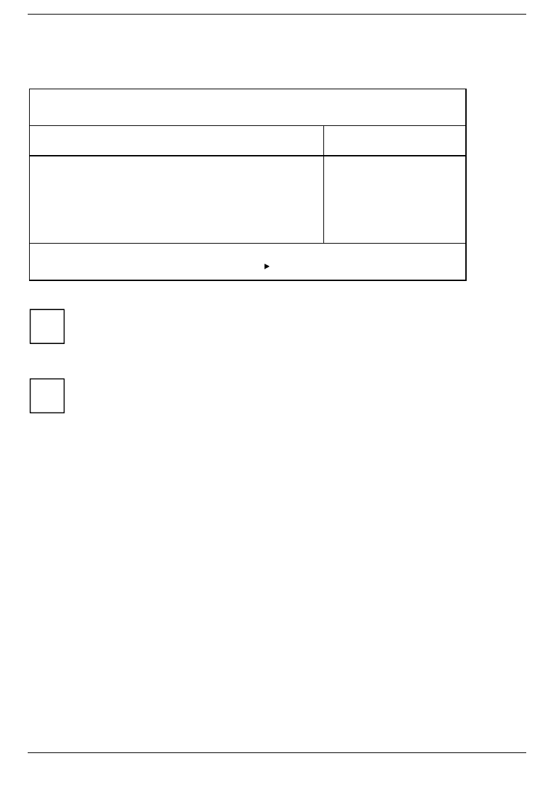
BIOS Setup Advanced menu - Advanced system settings
54 A26391-K84-Z100-1-7619
PCI Devices - PCI configuration
This field calls the submenu to select the settings for the PC card controller and the PCI slots.
Phoenix BIOS Setup
Advanced
PCI Devices Item Specific Help
Cardbus Controller Select: [External/Internal]
PCI IRQ line 1: [9]
PCI IRQ line 2: [9]
PCI IRQ line 3: [10]
F1 Help ↑↓ Select Item Space Change Values F9 Setup Defaults
ESC Exit ← → Select Menu Enter Select Sub-Menu F10 Previous Values
Example for submenu PCI Devices
iIf you use an operating system that does not support plug & play, you must select No for the
Plug&Play O/S field in the Advanced menu to ensure that the PC card controller is switched
on by the system BIOS.
Cardbus Controller Select - Settings of the PC Card Controller
iThis setting is only effective when a QuickPort Plus or a QuickPort S is connected. If the
QuickPort is not connected, the controller in the notebook is always configured to the
compatible address 3E0h.
This field specifies the order of the CardBus controller
External/Internal
The controller in the QuickPort Plus/S is configured to the compatible address 3E0h. A
secondary address is assigned to the controller in the notebook.
Internal/External
The controller in the notebook is configured to the compatible address 3E0h. A
secondary address is assigned to the controller in the QuickPort Plus/S.
External only The controller in the QuickPort Plus/S is configured to the compatible address 3E0h.
The controller of the notebook is disabled.

Advanced menu - Advanced system settings BIOS Setup
A26391-K84-Z100-1-7619 55
PCI IRQ line 1,2,3 - Setting the PCI interrupt
This field is used to specify which PCI interrupt is to be switched to which ISA interrupt.
A multifunctional PCI board can use all PCI interrupts, if need be.
If you use a setting other than Auto Select, the Plug&Play functionality of the system BIOS for PCI
boards is deactivated.
For monofunctional PCI boards, the PCI interrupt line 1 is assigned to the PCI slot1 and the PCI
interrupt line 2 to the PCI slot 2.
Auto The PCI interrupt is automatically assigned in accordance with the plug & play
guidelines.
3, 4, 5, 7, 9, 10, 11
The PCI interrupt is switched to the selected ISA interrupt. You may not select an ISA
interrupt that is used by a component on the system board (e.g. controller) or an ISA
board.
Disabled No PCI interrupt is used for the PCI board in the assigned PCI slot. You should only
select this setting if you are sure that the corresponding PCI board does not require an
interrupt. Otherwise, errors may occur.
iPCI IRQ line 1 is used by the following PCI boards: PC card controller in the notebook and in
QuickPort Plus, SCSI controller in the MobiDock.
PCI IRQ line 1 or line 2 is used by one of the PCI boards in the MobiDock. This depends on
the PCI board.
PCI IRQ line 2 is used by both CardBus controllers (notebook and MobiDock.
PCI IRQ line 3 is used by the USB controller in the notebook.
Plug & Play O/S
This field is used to define the Plug&Play functionality. Plug&Play means that inserted modules are
automatically recognized and installed if they support Plug&Play.
Yes The operating system takes over some of the Plug&Play functions. You should select
this setting only if the operating system (e.g. Windows 9x) supports Plug&Play.
No The BIOS takes over the complete Plug&Play functionality.
Enable ACPI - ACPI functionality
This field is used to define the ACPI functionality.
Yes Only set it to Yes when the operating system supports ACPI (Windows98).
No No ACPI function is active.

BIOS Setup Advanced menu - Advanced system settings
56 A26391-K84-Z100-1-7619
Reset Configuration Data
This field is used to specify whether the configuration data is reset and reinitialized when the system is
started.
No The Plug&Play functionality ascertains the current configuration data and uses it to
initialize the installed modules and drives. There is no update when the system is
started.
Yes When the system is started the old configuration data is reset. The new configuration
data is determined by means of the Plug&Play functionality. The mounted modules and
drives are then initialized with this data.
iThis field only takes effect if the notebook is connected to a MobiDock.
Large Disk Access Mode - Hard disk access
This field is used to specify the type of hard disk access for large hard disks (more than 1024
cylinders, 16 heads). The default setting depends on the operating system used.
DOS the operating system uses MS-DOS-compatible hard disk accesses.
Other If the operating system uses hard disk accesses which are not MS-DOS-compatible
(e.g. Novell, SCO Unix).

Security menu - Setting up the security features BIOS Setup
A26391-K84-Z100-1-7619 57
Security menu - Setting up the security features
You can set up the following security features in the Security menu:
• Setting a supervisor password (in the field Set Supervisor password)
• Setting a user password (in the field Set User password)
• Set a hard disk password (in the Hard Disk Security submenu)
• Activating the password query for system startup (in the field Password on boot)
• Blocking access to the diskette (in the field Diskette access)
Phoenix BIOS Setup
Main Advanced Security Power Docking Boot Exit
Supervisor Password is Disabled
User Password is Disabled
Set Supervisor Password [Press Enter]
Set User Password Press Enter
Hard Disk Security
Password on boot: [Disabled]
Diskette access: [User]
Flash Update: [Disabled]
Item Specific Help
——————————————————————
F1 Help ↑↓ Select Item Space Change Values F9 Setup Defaults
ESC Exit ← → Select Menu Enter Select Sub-Menu F10 Previous Values
Example for Security menu
Supervisor Password is/User Password is - Password display
Disabled, Enabled
These fields indicate whether the appropriate password is installed or not.
Set Supervisor Password
This field enables you to install the supervisor password.
Set User Password
This field enables you to install the user password. However, you can only assign the user password if
a supervisor password has already been assigned.

BIOS Setup Security menu - Setting up the security features
58 A26391-K84-Z100-1-7619
Hard Disk Security - Setting hard disk passwords
This field calls the submenu to make the settings for the hard disk passwords.
Phoenix BIOS Setup
Security
Hard Disk Security Item Specific Help
HD1 Password is: Disabled
Set HD1 password: [Press Enter]
F1 Help ↑↓ Select Item Space Change Values F9 Setup Defaults
ESC Exit ← → Select Menu Enter Select Sub-Menu F10 Previous Values
Example for submenu PCI Devices
HD1 Password is
Disabled, Enabled
This field indicates whether the appropriate password is installed or not.
Set HD1 password
This field enables you to install the hard disk password. The hard disk password only applies to the
hard disk in the notebook and not the one in the MobiDock. If a hard disk password has already been
set, you must enter the set password before you can change or delete it.
Password on boot - Password query during system startup
Requirement: the supervisor password or user password must be installed.
This field is used to specify whether the password is to be queried when the operating system is
booted.
Disabled The password is queried only when BIOS Setup is called.
Enabled The password is queried before the operating system is booted and when BIOS Setup is
called.
Diskette access - Access privilege for disk drive
This field is used to specify whether diskettes can be accessed.
User Both users and the supervisor can access diskettes.
Supervisor Only a supervisor can access diskettes.
Flash update - Permission for BIOS update
This field specifies whether a BIOS flash update may be carried out on the notebook.
Disabled BIOS flash update not possible.
Enabled BIOS flash update is permitted.
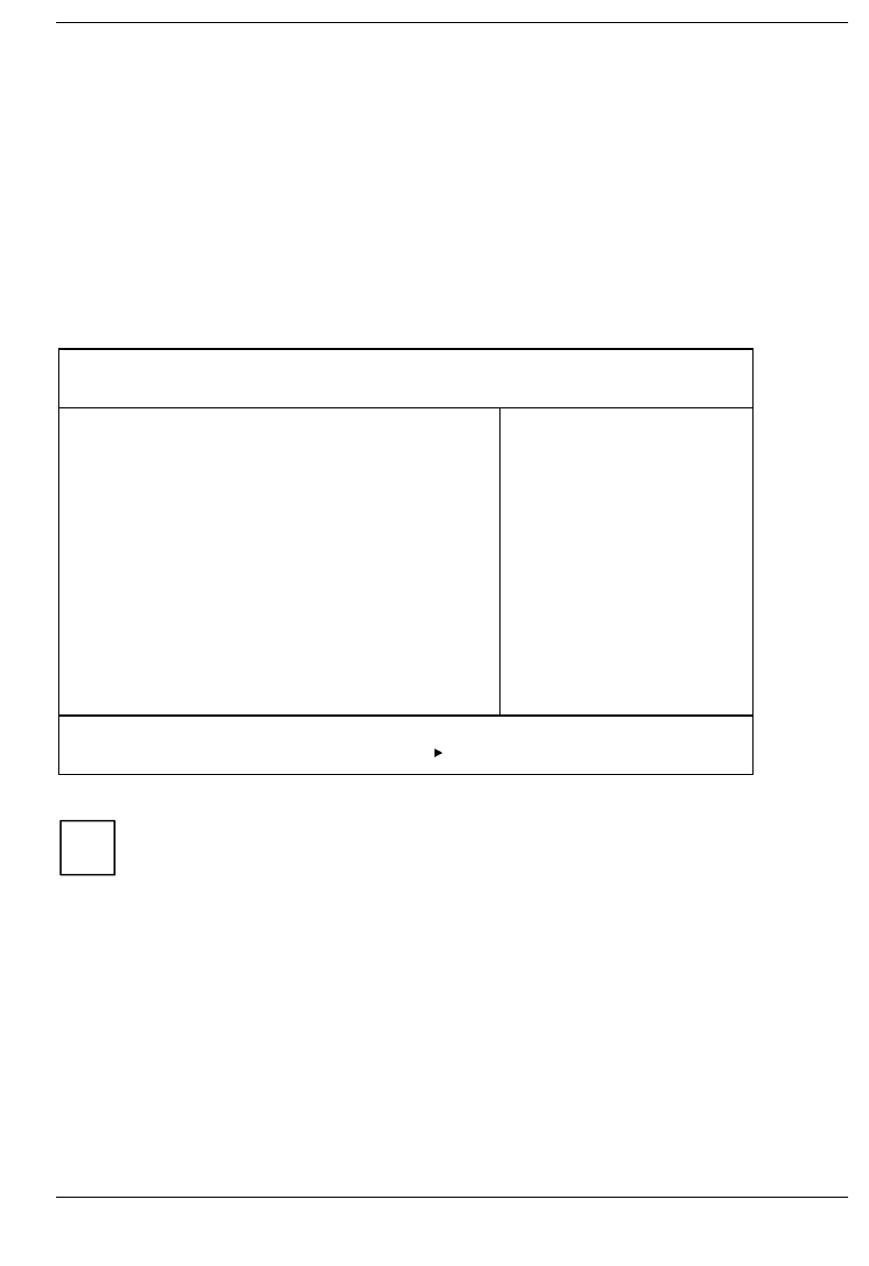
Power menu - Setting energy saving functions BIOS Setup
A26391-K84-Z100-1-7619 59
Power menu - Setting energy saving functions
You can set up the following energy saving functions in the Power menu
• Effectiveness of energy saving functions (in the PM Control field)
• Extent of energy saving functions (in the Power Savings field)
• Standby timer (in the Standby Timeout field)
• Suspend timer (in the Suspend Timeout field)
• Automatic display power-down in the Video Timeout field)
• Select the mode of the LID switch (in field of LID switch)
• Enter suspend mode if the battery capacity is low (in the Battery Low Suspend field)
• Suspend mode selection (in the Suspend Mode field)
• Resume condition selection
(in the Resume On Modem Ring, Resume On Time, Resume Time fields)
Phoenix BIOS Setup
Main Advanced Security Power Docking Boot Exit
PM Control: [Battery Powered Only]
Power Savings: [Customize]
Standby Timeout: [5 min]
Auto Suspend Timeout: [10 min]
Hard Disk Timeout: [2 min]
Video Timeout: [2 min]
LID Switch: [LCD off]
Battery Low Suspend: [Enabled]
Suspend Mode: [Save to DRAM]
Resume On Modem Ring: [OFF]
Resume On Time: [OFF]
Resume Time: [00:00:00]
Cooling Control: [Performance]
Item Specific Help
——————————————————————
F1 Help ↑↓ Select Item Space Change Values F9 Setup Defaults
ESC Exit ← → Select Menu Enter Select Sub-Menu F10 Previous Values
Example for menu Power
iIf the field Enable ACPI is set to Yes, the energy saving functions are not controlled by the
BIOS, but instead by the operating system.
PM Control - Effectiveness of the energy saving functions
This field determines when the energy saving functions are active.
Battery Powered Only
The energy saving functions are only enabled for battery operation.
Always Enable The energy saving functions are always enabled (battery and mains operation).
Disabled None of the energy saving functions is effective.

BIOS Setup Power menu - Setting energy saving functions
60 A26391-K84-Z100-1-7619
Power Savings - Extent of energy saving functions
This field is used to define the extent of the following energy saving functions.
Customize The functions set in the fields Standby Timeout, Suspend Timeout, Hard Disk Timeout,
Video Timeout, Hardware Dozemode and Battery Low Suspend are effective in power
management
Maximum Performance/Maximum Battery Life
These entries call predefined settings, thus determining the extent of energy saving.
Disabled None of the energy saving functions is effective.
Standby Timeout
This field can only be changed, if the PowerSaving field is set to Customize.
1, 2, 5, 10, 20, 30 min
The system switches to standby mode after the specified time without system activity.
Off The PC does not switch to standby mode
Auto Suspend Timeout - Suspend mode
This field can only be changed, if the PowerSaving field is set to Customize.
1, 2, 5, 10, 20, 30 min
The system switches to suspend mode after the specified time without system activity.
Off The PC does not switch to suspend mode

Power menu - Setting energy saving functions BIOS Setup
A26391-K84-Z100-1-7619 61
Hard Disk Timeout - Hard disk energy saving function
This field can only be changed, if the PowerSaving field is set to Customize.
1, 2, 5, 10, 20, 30 min
The hard disk drive motor is switched off after the specified time without system
activity.
Off The PC does not switch off the hard disk drive motor.
Video timeout - Energy saving functions for the monitor
This field can only be changed, if the PowerSaving field is set to Customize.
2, 5, 10, 15, 20, 30 min
The screen goes dark after the specified time without system activity.
Off The screen does not go dark.
LID Switch - LID mode
This field specifies which mode the device is switched into when the notebook monitor is closed.
LCD Off The screen goes dark.
Standby Mode The system is switched into the standby mode (see Standby Mode)
Suspend Mode The system state is buffered in the DRAM memory. After folding open the monitor, the
switch-on button must be pressed to return to the state prior to closing.
Battery Low Suspend - Suspend mode for low battery
capacity
This field indicates whether a switch is to be made to suspend mode when the battery capacity is low.
Enabled The function is enabled; the device is switched to suspend mode when the battery
capacity is low.
Disabled The function is disabled.

BIOS Setup Power menu - Setting energy saving functions
62 A26391-K84-Z100-1-7619
Suspend Mode
This field specifies where the system state is saved when the device is switched to suspend mode.
Save to DRAM The system state is buffered in the DRAM memory.
Save to Disk The system state is saved to the hard disk, the system is switched off.
Resume On Modem Ring - Switching on for modem ring
This field specifies whether the notebook is booted when a call is made to the connected modem.
This field can be operated only if Suspend Mode is set to Save to DRAM.
OFF The function is disabled.
ON The function is enabled.
Resume On Time - Switching on at a fixed time
This field specifies whether the notebook is booted at a specific time. The time is set in the Resume Time
field.
This field can be operated only if Suspend Mode is set to Save to DRAM.
OFF The function is disabled.
ON The function is enabled.
Resume Time - Setting the switch-on time
This field specifies whether the notebook is booted at a specific time.
This field can only be set if the Suspend Mode is set to Save to DRAM and the Resume On Time field is set
to ON.
Cooling Control - Cooling mode
This field defines the cooling mode.
Performance When a certain temperature limit is exceeded in the system, the integrated fan is
switched on first. If the temperature nevertheless continues to increase, the clock
frequency of the processor is also reduced.
Silence First the clock frequency of the process is reduced, then the integrated fan is switched
on.
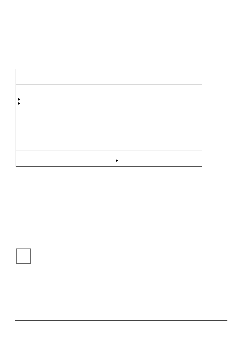
Docking menu - Configuring the MobiDock BIOS Setup
A26391-K84-Z100-1-7619 63
Docking menu - Configuring the MobiDock
The Docking menu is only available if the notebook is connected to a MobiDock.
You can set up the following security features in the Docking menu
• external floppy disk drive (in the Diskette B: field)
• external hard disk drive (in the fields marked IDE Adapter 1)
• loading the system from hard disk C: (in the Boot Hard Disk field)
• MobiDock password (in the Docking Station Password is field)
Phoenix BIOS Setup
Main Advanced Security Power Docking Boot Exit
Diskette B: [Not installed]
IDE Adapter 1 Master [None]
IDE Adapter 1 Slave [None]
Boot Hard Disk: [Notebook]
Integrated IDE adapter [Secondary]
SCSI Controller: [Enabled]
Docking Station Password is [Disabled]
Set Docking Station Password [Press Enter]
Item Specific Help
——————————————————————
F1 Help ↑↓ Select Item Space Change Values F9 Setup Defaults
ESC Exit ← → Select Menu Enter Select Sub-Menu F10 Previous Values
Example of the Docking menu
Floppy disk B: - Set external floppy disk drive
This field shows the type of the floppy disk drive in the MobiDock.
Not Installed A floppy disk drive is not installed.
360KB - 5 1/4", 720KB - 3 1/2", 1.2MB - 51/4", 1.4MB - 3 1/2", 2.8MB - 3 1/2"
The entry depends on the floppy disk drive in the MobiDock.
IDE Adapter 1 Master/IDE Adapter 1 Slave -
Setting external hard disk drives
iThis setting is only possible when the Onboard IDE-Adapter field in the Advanced/Integrated
Peripheral menu is set to Auto or Primary.
This field shows the type of the hard disk drive in the MobiDock. How to change the settings for the
hard disk drives is described in the IDE Adapter 0 field of the Main-Setup.

BIOS Setup Docking menu - Configuring the MobiDock
64 A26391-K84-Z100-1-7619
Boot Hard Disk - Specifying hard disk for system load
iThis setting is only possible when the Onboard IDE-Adapter field in the Advanced/Integrated
Peripheral menu is set to Auto or Primary.
This field is used to specify which hard disk is to be treated as hard disk C:. This is the hard disk from
which the operating system is loaded.
Notebook The operating system is loaded from the notebook's hard disk.
MobiDock The operating system is started from the 1st MobiDock hard disk.
Integrated IDE Adapter - Setting the IDE Controller in the
MobiDock
iThis setting is only possible when the Onboard IDE-Adapter field in the Advanced/Integrated
Peripheral menu is set to Auto or Primary.
This field is used to enable or disable the IDE controller in the MobiDock.
Secondary The IDE drives in the MobiDock are operated on the secondary IDE channel (IRQ15).
Disabled The IDE controller in the MobiDock is disabled.
SCSI Controller - Setting the MobiDock SCSI controller
This field is used to enable or disable the SCSI controller in the MobiDock.
Enabled The SCSI controller in the MobiDock is enabled.
Disabled The SCSI controller in the MobiDock is disabled.
Docking Station Password is - Password display
This field is only available if the notebook is connected to a MobiDock. This field indicates whether
MobiDock access is controlled by means of a password.
Enabled You have to enter the docking station password in order to access the MobiDock.
Disabled You can access the MobiDock without having to enter a password
iYou should set a docking station password to prevent unauthorized access to the MobiDock.
Set Docking Station Password -Setting the
Docking Station Password
This field enables you to install the docking station password.

Boot menu - Defining boot sequence BIOS Setup
A26391-K84-Z100-1-7619 65
Boot menu - Defining boot sequence
In the Boot menu you define the sequence in which the system BIOS searches the drives for system
files to start the operating system
Phoenix BIOS Setup
Main Advanced Security Power Docking Boot Exit
1. Diskette Drive
2. Hard Drive
3. CD-ROM Drive
Item Specific Help
——————————————————————
F1 Help ↑↓ Select Item Space Change Values
ESC Exit ← → Select Menu
Example for Boot menu
Default entry:
1. Diskette Drive
2. Hard Drive
3. CD-ROM Drive
To change this boot sequence, proceed as follows:
Place the cursor on the entry for the drive you to which wish to move forward or back.
Press the function key to move the selected drive up.
Use the key or the Space key to move forward the selected drive

BIOS Setup Exit menu - Exiting BIOS Setup
66 A26391-K84-Z100-1-7619
Exit menu - Exiting BIOS Setup
In the Exit menu, you can save your settings and exit BIOS Setup.
Phoenix BIOS Setup
Main Advanced Security Power Docking Boot Exit
Save Changes & Exit
Exit Without Saving Changes
Get Default Values
Load Previous Values
Save Changes
Item Specific Help
——————————————————————
F1 Help ↑↓ Select Item Space Change Values F9 Setup Defaults
ESC Exit ← → Select Menu Enter Select Sub-Menu F10 Previous Values
Example for menu Exit
Save Changes & Exit - Saving and Exiting
This field saves the settings you have made and exits BIOS Setup.
Exit Without Saving Changes
This field exits BIOS Setup without saving the new settings.
iIf you have made changes to passwords, these changes are still saved.
Get Default Values
This field reverts all settings to the default values
Load Previous Values
This field resets all values to those that were active when the BIOS-Setup was started.
Save Changes
This field saves the settings you have made.

A26391-K84-Z100-1-7619 67
Property and data protection
The software functions on your notebook enable you to protect your system and personal data in a
number of ways against unauthorized access. By combining these options, you can achieve optimum
protection for your system.
Security functions under Windows 9x
Under Windows 9x you can activate a screen saver and protect it with a password. Only those users
who know the password can deactivate the screen saver and access any open files.
BIOS Setup security functions
The Security menu in BIOS Setup offers you various options for protecting your system and personal
data against unauthorized access. By combining these options, you can achieve optimum protection
for your system.
Preventing unauthorized BIOS Setup calls
You can activate this protection by setting a supervisor password in the Security menu
(Set Supervisor Password).
Preventing unauthorized system access
You can activate this protection by setting a user password in the Security menu (Set User Password). In
addition, you must select the entry Enabled in the Password on boot field.
Preventing unauthorized access to the hard disk drives
You activate this protection when you set hard disk passwords in the Hard Disk Security submenu of
the Security menu (Set HD1/HD2 password).
If set, the hard disk passwords are checked at each system startup, regardless of whether
Password On Boot is set to Enabled or Disabled.
Preventing unauthorized access to floppy disk drive
To activate this protection, select the value Supervisor for the Diskette access field in the Security menu.
Preventing unauthorized access to MobiDock
You can only activate this protection if the notebook is connected to a MobiDock.
You can activate this protection by setting a docking station password in the Docking menu
(Set Docking Station Password).
Preventing unauthorized update of flash BIOS
To activate this protection, select the value Disabled for the Flash Update field in the Security menu.

Property and data protection
68 A26391-K84-Z100-1-7619
Setting passwords
The Supervisor password prevents unauthorized callup of BIOS Setup. BIOS Setup can be called only by
those who know the Supervisor password.
The user password prevents unauthorized access to your notebook. With the user password you can
prevent booting of the operating system. The system can be accessed only by those who know the
user password. A user password can only be set if a supervisor password is also set.
iPasswords can be at most seven characters long. All alphanumerical characters can be
used; no differentiation is made between upper-case and lower-case.
Passwords are not displayed as they are entered.
If you have forgotten a password contact your system administrator or contact our customer
service.
To set or change a password, proceed as follows:
Call BIOS Setup and select the Security menu (see "Settings in BIOS Setup"). You must
additionally change into the Hard Disk Security submenu for the hard disk passwords.
Mark the Set Supervisor Password or Set User Password or Set HD password field and press the
Enter key.
The following applies for setting a hard disk password: if a hard disk password is already set, you are
prompted to input it. Enter the former hard disk password and press the Enter key.
You are asked to enter a password:
Enter new Password:
Enter the password and press the Enter key.
You are asked to confirm the password:
Re-enter new Password:
Enter the password again and press the Enter key.
The new password is saved.
Notice: Changes have been saved [continue]
To prevent booting of the operating system, mark the Password on boot field and select the value
Enabled.
If you do not want to make any other settings, you can exit BIOS Setup.
Select the option Save Changes & Exit in the Exit menu.
The notebook is rebooted and the new password is effective.

Property and data protection
A26391-K84-Z100-1-7619 69
Canceling password
iIf you cancel the supervisor password, you automatically deactivate the user password.
To cancel a password (without setting a new password):
Call BIOS Setup and select the Security menu (see "Settings in BIOS Setup"). You must
additionally change into the Hard Disk Security submenu for the hard disk passwords.
Mark the Set Supervisor Password or Set User Password or Set HD password field and press the
Enter key.
If a password has already been assigned, you will be asked to enter the old password (Enter Current
Password). Enter the old password and press the Enter key.
You are asked to enter a password:
Enter new Password:
Press the Enter key twice.
Select the option Save Changes & Exit in the Exit menu.
The notebook is rebooted and the password is canceled.


A26391-K84-Z100-1-7619 71
Troubleshooting and tips
!Take note of the safety hints in the chapter "Important notes", when you connect or
disconnect cables.
If a fault occurs, try to correct it as described. If you fail to correct the problem, proceed as follows:
Switch off the notebook.
Make a note of the steps and the circumstances that led to the fault. Also make a note of any
error messages displayed.
Contact your sales office or customer service.
Installing new software
When installing programs or drivers, important files may be overwritten and modified. To be able to
access the original data in the case of any problems following installation, you should make a backup
of the your hard disk prior to installation.
The notebook does not start after switchon
If the notebook does not start after switchon, this may be due to the following causes:
The battery is not installed correctly
Switch off the notebook.
Check whether the battery is installed correctly in its compartment.
Switch on the notebook.
The battery is dead
Recharge the battery or install a fully charged battery.
The power adapter is not connected correctly
Switch off the notebook.
Check whether the power adapter is connected correctly to the notebook.
Check whether the power cable is plugged properly into the power adapter and into the power
outlet.
Switch on the notebook. The indicator on the power adapter should light up.
The display of the notebook remains blank
If your screen remains blank this may have the following causes:
Monitor is switched off
Press a key or enter the user password

Troubleshooting and tips
72 A26391-K84-Z100-1-7619
If the notebook is connected to a MobiDock in which a PCI VGA adapter is installed, the notebook's
display is always switched off.
The notebook's display is difficult to read
If the display is difficult to read, it can have the following reasons:
Reflexes
Turn the notebook or alter tilt of the display.
Defective pixels on the screen
Pixel faults in the form of permanently lit, unlit or different-colored pixels can occur with LCD monitors.
Up to ten pixel faults on the screen does not constitute grounds for exchanging the unit. Exceptional
cases are:
• if two pixel faults are lying directly beside each other
• if three pixel faults occur in a 5-mm diameter circle
The external monitor stays blank
If your screen remains blank this may have the following causes:
Monitor is switched off
Switch the external monitor on.
Screen has been blanked
Press any key to continue.
Brightness control is set to dark
Set the brightness control to light. For detailed information, please refer to the Operating Manual
supplied with your monitor.
The notebook has been configured to drive the internal display
Press the key combination + or change the Display Device Selection in Main Setup to
CRT or LCD&CRT.
The external display's power cable or data cable is not connected properly
Switch off the external monitor and the notebook.
Check whether the power cable is plugged properly into the power adapter and into the power
outlet.
Check whether the data cable is properly connected to the notebook and the external monitor (if it
is plugged in with a connector).
Switch on the external monitor and the notebook.

Troubleshooting and tips
A26391-K84-Z100-1-7619 73
The external display is blank or the image is unstable
The wrong frequency has been selected for the external monitor or for the application program.
Terminate the application program in Windows 9x with + . If the error persists after the
program has been terminated, switch the external monitor off, wait at least three seconds, and
then switch the external monitor on again.
Set the screen resolution required by the application. Select the Start button Select the System
control item under Settings. Double-click on the Display symbol. Select the required screen
resolution in the Settings register card of the Resolution field.
The notebook stops working
If the notebook stops working, this may have the following reasons:
The notebook is in Standby or Suspend mode
Reactivate the notebook by pressing a key (Standby mode) or by switching it on (Suspend mode).
An application program has caused the malfunction
Close the application program or restart the notebook by switching it on/off or with a warm boot.
The battery is dead
Recharge the battery or install a fully charged battery.
The touchpad does not work
If the touchpad does not work, it can have the following reasons:
Incorrect setting in Setup
Check whether the field PS/2 Mouse in the Main Setup is set to Enabled or to Auto Detect.
External PS/2 mouse connected
The touchpad remains deactivated if an external PS/2 mouse is connected to the notebook.
The mouse does not work
If the connected mouse does not work, it can have the following reasons:
Incorrect setting in Setup
Check whether the PS/2 Mouse field is set to Enabled (for a PS/2 mouse) or Disabled (for a serial
mouse) in the Main Setup.
Check the COM Port field in the submenu Integrated Peripherals of the Advanced Setup to ensure
that serial port is enabled and set correctly.
Mouse driver not loaded
Check whether the required mouse driver is properly installed and is present when the application
program is started. Detailed information can be found in the User Guides of the mouse or
application program.
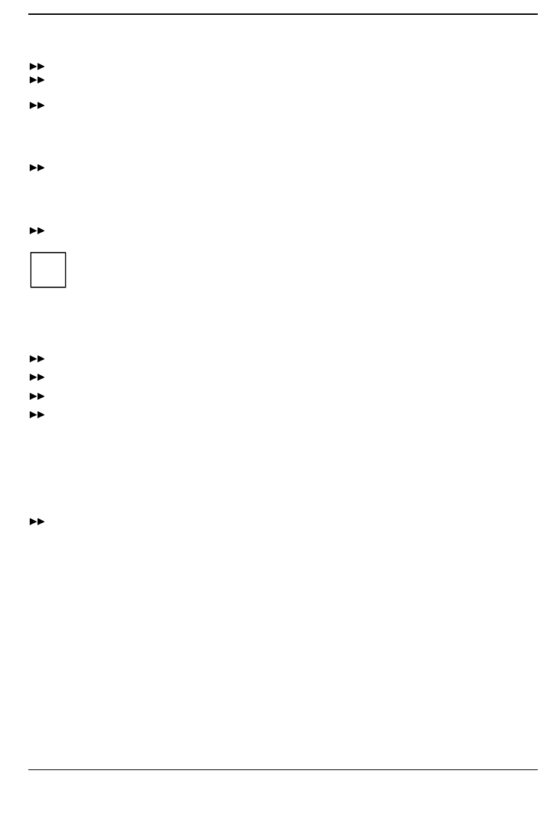
Troubleshooting and tips
74 A26391-K84-Z100-1-7619
Mouse not connected
Switch off the notebook.
Check whether the mouse cable is connected correctly to the notebook.
If you use an adapter or extension lead with the mouse cable, check the connector.
Switch on the notebook.
The floppy disk cannot be written
Check whether that floppy disk is OK and is not write-protected.
The notebook's date or time is incorrect
Set the time and/or date in the Main Setup.
iIf the date and time are repeatedly incorrect when you switch on the notebook, the backup
battery that supplies the internal clock is dead.
Connect the notebook via its power adapter to a wall outlet. The backup battery will charge
fully in roughly two days.
The printer does not print
Makes sure that the printer is switched on and on-line (see the manuals supplied with the printer).
Check that the printer cable connecting the notebook and the printer is connected properly.
Check that the correct printer driver is installed.
Check the submenu Integrated Peripherals of the Advanced Setup to ensure that the port you are
using is set correctly. The COM Port or Parallel Port or Parallel Port Mode setting, should match
the settings in your application program under Windows x.
The PC card (PCMCIA card) cannot be accessed
If you are working under Windows for Workgroups:
Set the value to No for the fields Plug & Play O/S and Reset Configurtion Data in BIOS Setup in
Advanced Setup.

Troubleshooting and tips
A26391-K84-Z100-1-7619 75
Acoustic warnings
A beep sounds every few seconds
The battery is almost drained.
Charge the battery.
One long tone, pause, three long tones, pause, three long tones, pause, one long tone
No main memory is installed in the notebook.
Install at least 16 MB of main memory.
A single continuous beep
The notebook cannot switch to standby or suspend mode because hard disk or diskette accesses take
place or there is no space provided on the hard disk.
Wait until the hard disk or diskette accesses have terminated, or set up the required storage
space on the hard disk.
Three long beeps
The notebook cannot restore the programs that were active when it switched to Suspend mode.
Error messages on the screen
This section describes the error messages generated by the system BIOS. Error messages displayed
by the operating system or programs are described in the relevant manuals.
Diskette read failure - press F1 to retry boot
The inserted system disk is defective
Insert another system disk.
Press function key .
No boot device available - press F1 to retry boot
The operating system cannot be loaded
Insert a system disk.
Press function key .
No boot sector on fixed disk - press F1 to retry boot
The operating system is not installed on the hard disk or the hard disk has not been formatted.
Insert a system disk.
Press function key .
No devices detected
The PC card (PCMCIA) interface cannot be initialized.
Set the Plug & Play O/S field to No in the Advanced-Setup of the BIOS-Setup.
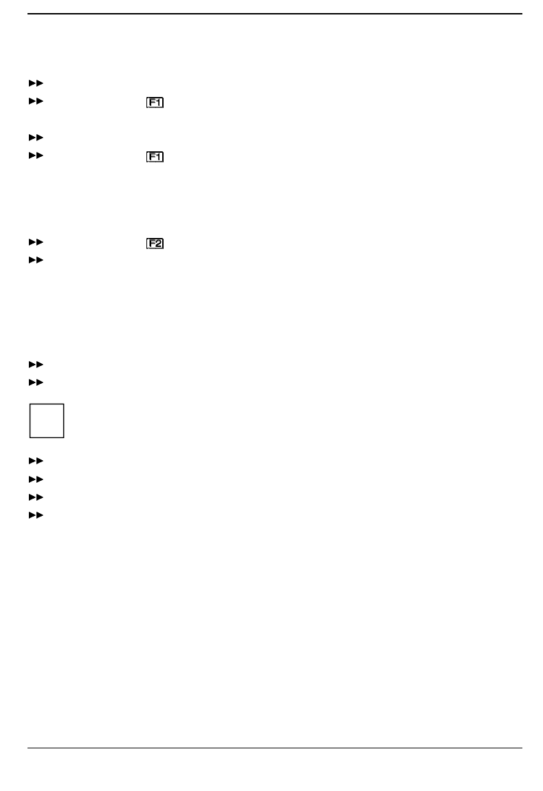
Troubleshooting and tips
76 A26391-K84-Z100-1-7619
Not a boot disk - press F1 to retry boot
The disk in the floppy drive is not a system disk.
Remove the floppy disk from the drive.
Press function key .
If you wish to boot from floppy disk:
Insert a system disk.
Press function key .
Real time clock failure
Invalid configuration information - please run setup program
Press the F1 key to continue, F2 to run the setup utility
The system configuration information is incorrect.
Press function key .
Reconfigure the system.
If the error message is displayed again, the notebook's backup battery is empty.
Connect the notebook via its power adapter to a grounded wall outlet or install a fresh battery. The
backup battery will charge fully in roughly two days.
Restoring the hard disk contents under Windows 9x
Insert the Windows 9x startup disk into the floppy disk drive and switch the notebook on.
Follow the instructions on the screen.
iDetailed PC knowledge is required for manual partitioning.
Insert the Windows 9x OEM CD into the CD-ROM drive.
Start the Setup program on the CD.
Insert the Drivers and Utilities CD into the CD-ROM drive.
Install the drivers.
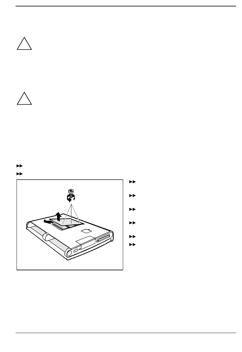
A26391-K84-Z100-1-7619 77
System expansions
!Only qualified technicians may repair the device. Unauthorized opening or incorrect repair
may greatly endanger the user (electric shock, fire risk).
Install only system expansions that satisfy the requirements and rules governing safety, RFI
and electromagnetic compatibility and relating to telecommunications terminal equipment
(see the chapter "Important notes").
Memory expansion
!Use only memory expansion which has been released for your notebook. (32, 64 Mbyte
modules, SD RAM, JEDEC 144 pin SO DIMM)
Never use force when installing or removing memory modules.
Make sure that foreign objects do not fall into the memory module compartment.
The main memory of your notebook can be expanded to 32 - 192 Mbyte using up to three 32 or
64 Mbyte memory modules. The notebook will not start without memory modules, as no fixed main
memory is installed.
Installing/removing memory expansion
Switch off the notebook.
Remove the battery.
1
2
3
Pull the power plug of the power adapter out
of the power outlet.
Close the display of the notebook so that it
locks into place.
Disconnect all cables connected to
notebook.
Place the notebook bottom-up on a flat
surface.
Remove the screws (1).
Lift the cover (2) and pull it in the direction of
the arrow (3) from the notebook.
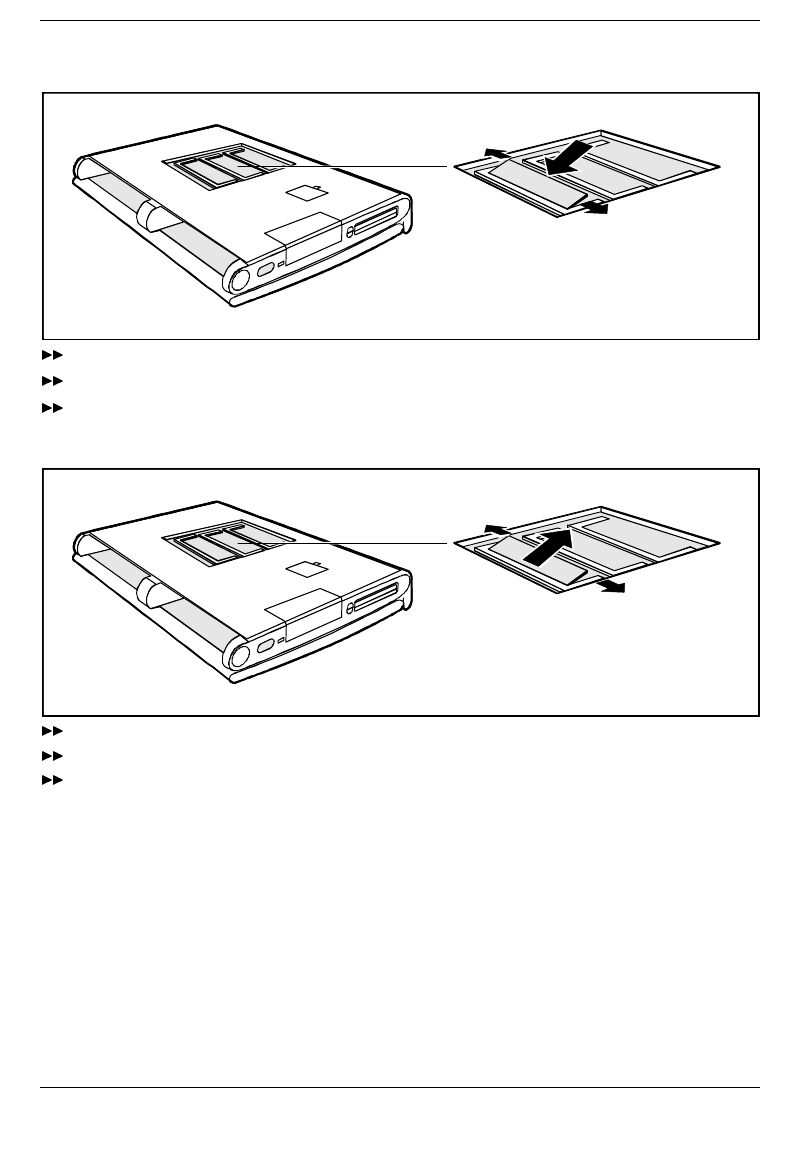
System expansions Memory expansion
78 A26391-K84-Z100-1-7619
In order to install memory modules:
21
Insert the memory modules, contacts first, into the slot (1).
Carefully flap the memory module down (2) until you feel it latch in place.
Install the other memory modules in the same way.
In order to remove memory modules:
1
1
2
Carefully push the two mounting clips outwards (1). The memory module flaps upwards.
Slide the memory module out of its location (2).
Remove the other memory modules in the same way.
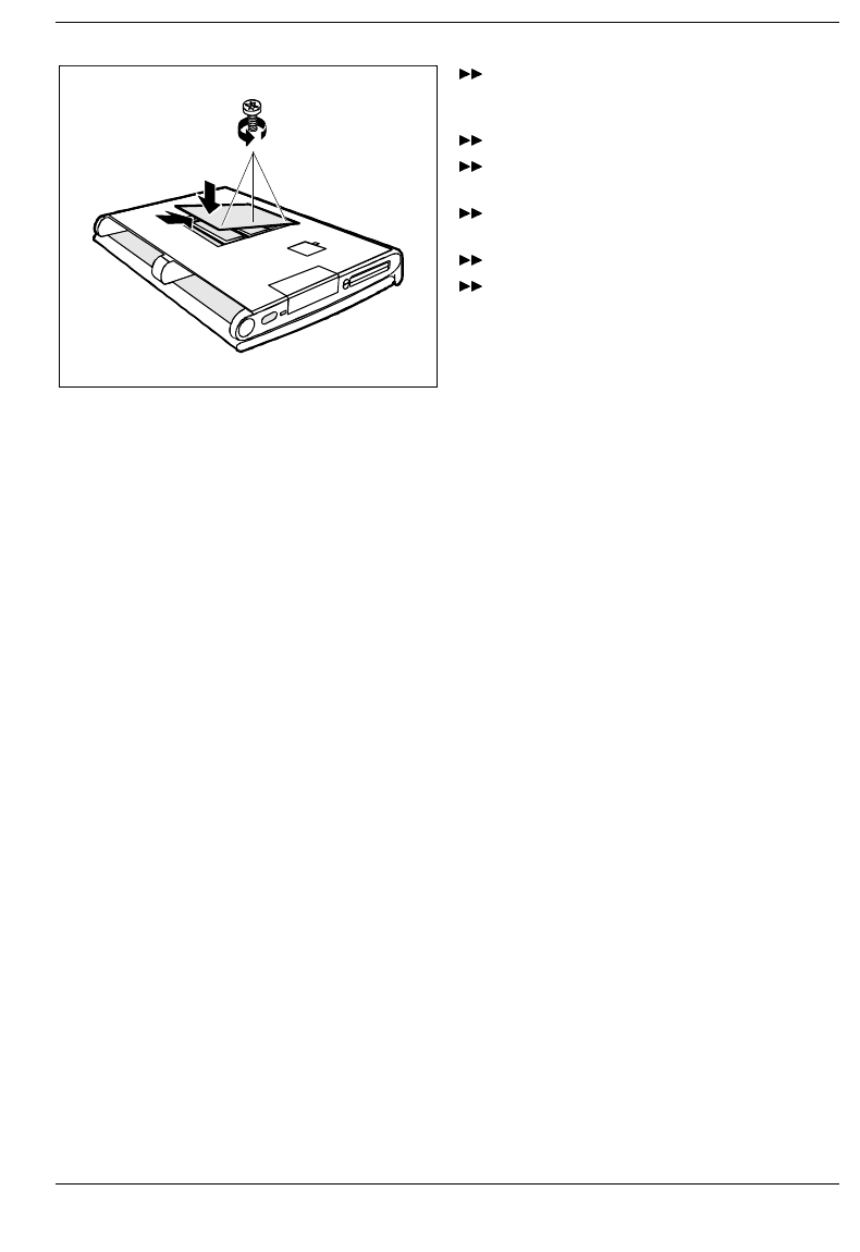
Memory expansion System expansions
A26391-K84-Z100-1-7619 79
2
3
1
Place the cover on its mounting location (1)
and flap it into place on the underside of the
notebook (2).
Fasten the cover with the screw (3).
Place the notebook bottom-down on a flat
surface.
Reconnect the cables that you disconnected
before.
Swing open the display.
Refit the battery.


A26391-K84-Z100-1-7619 81
Connecting external devices
!Disconnect all the devices from their respective power sources when you connect or
disconnect a device. Read the documentation on the external device before connecting it.
Do not connect or disconnect cables during a thunderstorm.
Always take hold of the actual plug body. Never unplug a cable by pulling the cable itself!
Connect and disconnect the cables in the order described below.
Connecting cables
• Turn off all power and equipment switches.
• Pull all power plugs out of the grounded power outlets.
• Connect all the cables to the notebook and the external devices. Please observe under all
circumstances the information provided in the chapter "Important notes".
• Plug all data communication cables into the utility sockets.
• Plug all power cables into the grounded power outlets.
Disconnecting cables
• Turn off all power and equipment switches.
• Pull all power plugs out of the grounded power outlets.
• Unplug all data communication cables from the utility sockets.
• Disconnect all the cables from the notebook and the external devices.
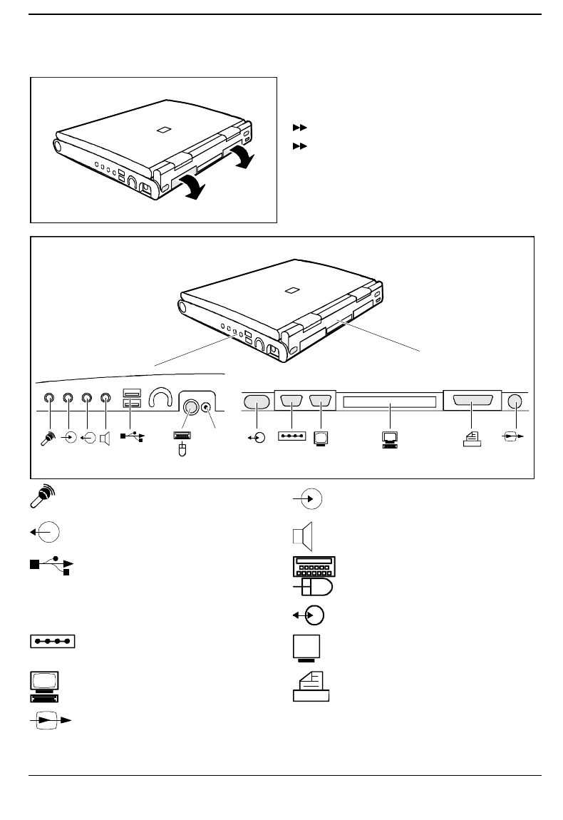
Connecting external devices
82 A26391-K84-Z100-1-7619
Port covers and connectors
If you wish to connect an external display or a
device with serial or parallel port, you must first
open the port cover.
Flap the port cover down.
Connect the desired device.
IR
DC-IN
Microphone jack Audio input (Line in)
Audio output (Line out) Audio output/Loudspeaker
USB - Universal Serial Bus PS/2 mouse port or keyboard port
DC IN DC socket IR IR Port
Serial port Video connector
Connection for QuickPort or MobiDock Parallel interface
TV out

Connecting external devices
A26391-K84-Z100-1-7619 83
Connecting devices with serial or parallel port
Connect the data cable of the external device to the appropriate port.
The serial port is configured by default as COM1. You can change the setting in the COM Port field in
the Integrated Peripherals submenu in Advanced Setup. The parallel port is configured by default as
LPT1. You can change the setting in the Parallel Port field in the Integrated Peripherals submenu in
Advanced Setup.
Connecting an external monitor
You can connect a VGA screen. The notebook screen controller for an external monitor supports
screen resolutions up to 1600 x 1200 with 65.536 colors (16 bits). If you wish to use a resolution
greater than 640 x 480, you must load the relevant display drivers (see the manuals supplied with your
display).
Plug the data cable of the monitor into the monitor port.
Connect the power cable of the external monitor to a power outlet and switch on the monitor.
Switch on the notebook.
Configure the display output in the Display Device Selection field in Main Setup or by pressing the
key combination + .
Select the resolution for the external monitor.
Connecting the mouse
Connect the mouse, depending on the type, to either the PS/2 mouse port or the serial port. The
touchpad and the touchpad buttons are disabled when you connect a mouse.
Switch on the notebook.
Set the PS/2 Mouse field in Main Setup to Disabled if you want to use a serial mouse (e g.
TrackMan).
Install the necessary device driver (see the manual supplied with the mouse).
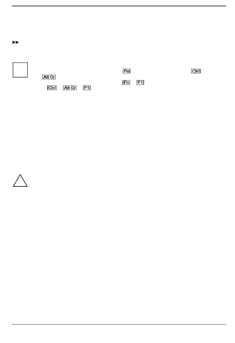
Connecting external devices
84 A26391-K84-Z100-1-7619
Connecting an external keyboard
Connecting an external keyboard does not disable the notebook's built-in keyboard.
Connect the external keyboard to the external keyboard port.
If you wish to connect a keyboard with a 5-pin connector you will require an adapter from 5-pin
DIN to 6-pin DIN mini connector.
iNever press the keys on the external and internal keyboards at the same time.
If the external keyboard does not have an key, you can press the right key and
the key together instead.
For example, to enter the key combination + on the external keyboard you would
press + + .
Connecting external audio devices
If you attach an external microphone, the built-in microphone is disabled. If you attach an external
loudspeaker, the built-in loudspeaker is disabled.
Connect the audio device (external microphone, external loudspeaker, audio output) to the appropriate
port.
Connecting a MobiDock or QuickPort
The manuals supplied with the MobiDock and the QuickPort describe how to connect the notebook.
!Read the MobiDock or QuickPort/QuickPortPlus manuals carefully before attempting to
connect the notebook.
Make sure that no PC cards or extracting tools for PC cards are projecting from the
notebook. No power adapter may be connected when you dock the MobiDock onto the
notebook.
If the notebook is connected to a MobiDock in which a PCI VGA board is installed, the notebook's
display is always switched off.
In case of problems with the display output on the external monitor, check the settings in the
Display Device Selection field in BIOS Setup in the Main menu.
Makes sure that any board installed in the MobiDock or the QuickPort/QuickPortPlus do not use I/O
addresses, interrupts or DMA channels already used by the notebook. Details of the I/O addresses,
interrupts and DMA channels are provided in the section "Technical data".
The maximum DMA transfer rate between MobiDock and notebook is of 5 Mbyte/second.
If necessary, you free I/O addresses (i.e. graphic controller) or interrupts (i.e. serial or parallel
interface). You do this by deactivating the relevant components in the BIOS-Setup.
When the MobiDock is switched off, you should remove the batteries from the notebook to prevent
MobiDock from causing long-term capacity loss to the batteries.
If you wish to operate IDE drives in the MobiDock, you must set the value Auto in the
Local Bus IDE Adapter field in BIOS Setup in the Integrated Peripherals submenu of the Advanced menu.
You cannot operate the floppy disk drive on the parallel port of the MobiDock.
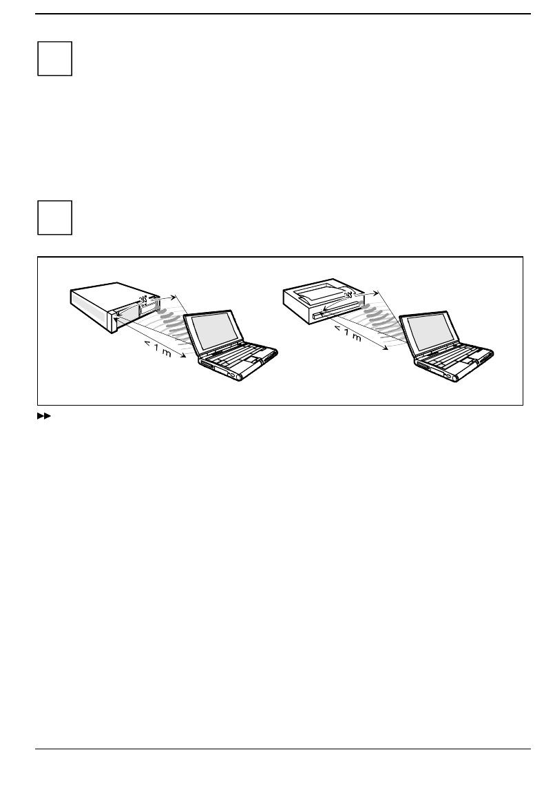
Connecting external devices
A26391-K84-Z100-1-7619 85
iYou should set a docking station password to prevent unauthorized access to the MobiDock.
Transferring data with the infrared interface
The infrared interface (Fast IrDA) at the back of the notebook enables wireless serial data transfer.
By default, the infrared interface is set to COM2 in the setup. You can change the setting in the
IrDA Port field in the Integrated Peripherals submenu in Advanced Setup.
iThe infrared interface can only be used, when the infrared interface is enabled in the
IrDA Port field in the Integrated Peripherals submenu in Advanced Setup.
Set up the infrared transmitter and receiver as illustrated above.
The devices may be no more than one meter apart. The infrared interface of one device must be
in the range of influence (horizontally approx. 30° and vertically approx. 15°) of the infrared
interface of the other device.


A26391-K84-Z100-1-7619 87
Technical data
Technical data for the notebook
Processor Pentium II as from 233 MHz
Numeric processor integrated in processor
Cache: 32 Kbyte integrated in processor
512 Kbyte synchronous Second Level Cache
Main memory 32 - 196 Mbyte SD RAM
3 slots for 32, 64 Mbyte modules
JEDEC 144 pin SO DIMM (may not be mixed)
System ROM (flash EPROM): 512 Kbyte for system and video BIOS
Disk drives: Floppy disk drive for 3 1/2 inch floppy disks
hard disk drive 2.5 inch,12.7 mm height,
CD ROM drive twenty speed or more
Display:
Display diagonal:
• LCD TFT/ADS
Resolution / colors:
LCD TFT 12.1 / LCD ADS 13 / LCD TFT 13.3
Backlit liquid-crystal transmissive display (LCD)
30.7 cm (12.1 inch) XGA Overhead Display
33.0 cm (13.0 inch) XGA ADS
33.8 cm (13.3 inch) XGA
1024x768 / 262.144 colors (18 bit)
Screen controller
• Video memory (SG-RAM):
• supported resolutions on external display
ATI-3D Rage LT Pro
4 Mbyte
640x480 / 16.7 million colors and 85 Hz
800x600/ 16.7 million colors and 85 Hz
1024x768 / 65.536 colors and 75 Hz

Technical data Technical data for the battery
88 A26391-K84-Z100-1-7619
Audio:
• Compatibility:
• A/D and D/A conversion:
Soundchip ESS1869
Soundblaster Pro, Ad lib, MS soundsystem
16 bit, stereo
input devices
• Keyboard:
• Touchpad (Length, Width) 86 keys
64 x 48 mm
Slots
• PC card (CardBus/PCMCIA): PCMCIA 2 x type II or 1 x type III,
PC card controller TI 1250, Zoomed-Video-Port
Ports
• PS/2 mouse/keyboard port:
• Port for MobiDock/QuickPort:
• Parallel port:
• Port for external monitor:
• Serial port:
• Loudspeaker:
• Microphone jack:
• Audio input:
• Audio output:
• Infrared interface (Fast IrDA)
• USB (Universal Serial Bus)
6-pin mini DIN female connector
female connector, 240-pin
25-pin female connector, bi-directional,
EPP/ECP capable
female connector, 15-pin
9-pin male connector, 16550 compatible
connector, stereo
connector, mono
connector, stereo
connector, stereo
Power consumption: 50 W max.
(notebook on with battery charging)
Permissible ambient temperature
• during operation:
• Transport: 5 °C .... 35 °C
-20 °C .... 60 °C
Dimensions (Width x Depth x Height): 309 mm, 256 mm, 28/46 mm
Weight with a battery: approx. 3 kg
Technical data for the battery
Rated voltage: 14.4 V
Rated capacity 40 Wh
Charging time (when not in operation): 3 hours (in the off state)
Operating time with a battery: approx. 2 hours
(depending on application)
Weight: 370 g

Technical data for the power adapter Technical data
A26391-K84-Z100-1-7619 89
Technical data for the power adapter
Primary
• Rated voltage:
• Frequency:
• max. rated current:
100 V to 240 V (automatic)
50 Hz to 60 Hz (automatic)
0.75 A / 1.5 A
Secondary
• Rated voltage:
• max. rated current: 19 V
2.6 A
Technical data for the car adapter
Primary
• Rated voltage: 10 V to 15 V
Secondary
• Rated voltage:
• max. rated current: 19 V
2.6 A
CD-ROM drive
Supported CD formats: • CD-Digital Audio
• CD-ROM (Mode 1 and Mode 2)
• CD-ROM XA (Mode 2, Form 1 and Form 2)
• CD-I (Mode 2, Form 1 and Form 2)
• CD-I Ready
• CD bridge
• Photo-CD (Single- and Multisession)
• Video-CD
Laser
• Class 1 Laser Product
• Type:
• Wave length:
• Power output:
Semiconductor GaA/As
780 nm
5 mW max.
DVD drive
Supported DVD/CD formats: • DVD- 5: 4.377 Gbyte
• DVD- 9: 7.959 Gbyte
• DVD-10: 8.754 Gbyte
• DVD-18: 15.917 Gbyte
• CD (Mode-1): 656.5 Mbyte
• CD (Mode-2): 748.8 Mbyte
Laser
• Class 1 Laser Product
• Type:
• Wave length:
• Power output:
Semiconductor GaA/As
650 nm
5 mW max.

Technical data Interrupt I/O addresses, and DMA assignment
90 A26391-K84-Z100-1-7619
Interrupt I/O addresses, and DMA assignment
Changeable internal settings:
Function I/O address IRQ DMA
Soundchip "ESS1869" 220h - 22Fh *
240h - 24Fh
260h - 26Fh
280h - 28Fh
Midi Play Unit
(MPU):
330h - 331h
300h - 301h
310h - 311h
320h - 321h
FM:
388h - 38Bh **
Gameport:
201h*
Control Interface:
800h-807h
810h-817h
820h-827h
830-837h
IRQ 5 * (LPT)
IRQ 7 (LPT)
IRQ 9
IRQ 10
IRQ 11
1
.
DMA:
DMA 1 *
DMA 0
DMA 3
2
.
DMA
:
DMA 3 *
DMA 0
DMA 1
Parallel port LPT 378h - 37Fh* =
378h - 37Fh =
3BCh- 3C5h =
278h - 27Fh =
IRQ 7*
IRQ 5
IRQ 7
IRQ 5
DMA 1 or DMA 3 in
ECP-mode
1. Serial port COM 3F8h - 3FFh* =
2F8h - 2FFh =
3E8h - 3EFh =
2E8h - 2EFh =
IRQ 4 / COM1 *
IRQ 3 / COM2
IRQ 4 / COM3
IRQ 3 / COM4
2. Serial port COM
= Fast IrDA 2F8h - 2FFh * =
3E8h - 3EFh =
2E8h - 2EFh =
IRQ 3 / COM2 *
IRQ 4 / COM3
IRQ 3 / COM4
DMA 0 *
DMA 1
DMA 3
* = default setting in BIOS-SETUP
** = default setting, when Audio is enabled

Interrupt I/O addresses, and DMA assignment Technical data
A26391-K84-Z100-1-7619 91
Fixed internal settings:
Function I/O address IRQ DMA
System Timer 040h-043h 0
Keyboard 060h, 064h 1
Interrupt controller 020h-021h, -0A0h-
0A1h 2
Floppy disk drive controller 3F0h-3F5h, 3F7h 6 2
System CMOS / Realtime clock 070h-071h 8
PC card controller
"Cirrus CL-PD 6832" automatically defined Shared IRQ
USB controller automatically defined Shared IRQ
Synaptics touchpad 12
Numeric processor 0F0h-0FFh 13
Intel 82371AB PCI bus
Master IDE controller 1F0h-1F7h, 3F6h 14
DMA controller 000h-00Fh, 081h-08Fh,
0C0h-0DFh 4
PCI bus CF8h-CFFh

Technical data Interrupt I/O addresses, and DMA assignment
92 A26391-K84-Z100-1-7619
Settings for external components (e.g. MobiDock, PC card):
Function I/O address IRQ DMA
2. IDE-Hard disk controller in the
MobiDock (PCI) 170h - 177h, 376h IRQ 15
Internal SCSI controller "Adaptec
AIC7850" in the MobiDock Automatically
recognized Shared IRQ
Max. two PCI slots in the MobiDock
(PCI to PCI Bridge) and defined! Shared IRQ
Max. two ISA slots in the MobiDock
(PCI to ISA Bridge) a) PnP-ISA: is automatically recognized
and defined (no shared IRQ)!
b) ISA (without PnP): depends on the
card setting!
PC card (PCMCIA cards):
max. 1x TypIII or 2x TypII
• I/O cards (modem, network board,
COM, SCSI etc.)
• memory cards (e.g. SRAM,
FLASH)
• ATA cards (e.g. Harddisk,
Sundisk)
PC cards require an IRQ (no shared
IRQ!), I/O addresses and/or a memory
area and possibly DMA.
(see also the documentation on the
PC card).
BIOS SETUP
PnP = Plug and Play
Shared IRQ:
Several PCI components can share one free ISA-IRQ (assignment of the IRQs is automatic).
Conflict situations with ISA cards can be prevented under DOS/WfW with the "ISA configuration utility"
disk, which you created using the batchfiles in the directory /PROGS/DISKS (IRQ, DMA, I/O address,
etc. are reserved for the ISA card and are therefore no longer available for the PCI bus!).
Under Windows 9x you can change the resource contentions manually with the "Device Manager".
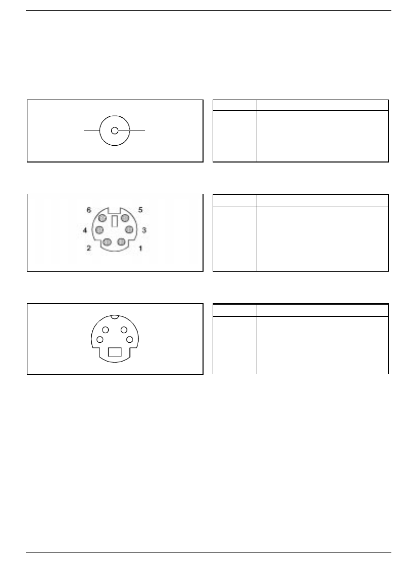
Port assignment Technical data
A26391-K84-Z100-1-7619 93
Port assignment
The assignment of the external ports are as follows:
DC jack (DC IN)
12
Pos.
1
2
Meaning
0 V
+19 V
Port for external keyboard or PS/2 mouse
Pos.
1
2
3
4
5
6
Meaning
Data
free
0 V
+5 V
Clock
free
TV out socket
12
34
Pos.
1
2
3
4
Meaning
0 V
0 V
SVideo_Y_FBAS_MUX
SVideo_COL
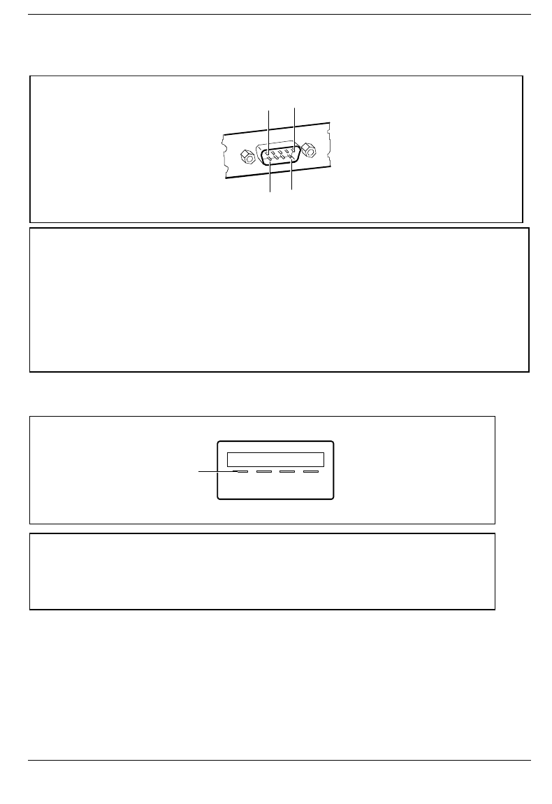
Technical data Port assignment
94 A26391-K84-Z100-1-7619
Serial port
15
69
Pos. Signal name Meaning
1
2
3
4
5
6
7
8
9
DCD (Data Carrier Detect)
RxD (Receive Data)
TxD (Transmit Data)
DTR (Data Terminal Ready)
Signal Ground
DSR (Data Set Ready)
RTS (Request to Send)
CTS (Clear to Send)
Ri (Ring Indicator)
Data Carrier Detect
Receive Data
Transmit Data
Data Terminal Ready
Signal Ground
Data Set Ready
Request to Send
Clear to Send
Ring Indicator
USB port
1
Pin Signal name Meaning
1
2
3
4
VCC
DATA_NEGATIVE
DATA_POSITIVE
GND
VCC of the Notebook
Data
Data
Ground
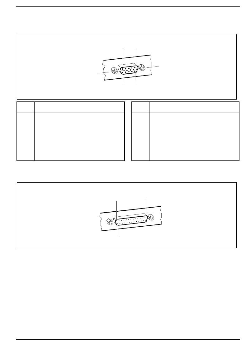
Port assignment Technical data
A26391-K84-Z100-1-7619 95
Port for external monitor
1
5
6
10
11
15
Pos. Meaning Pos. Meaning
1
2
3
4
5
6
7
8
Video output red
Video output green
Video output blue
reserved
DDC ground
Video ground red
Video ground green
Video ground blue
9
10
11
12
13
14
15
+5V
logic ground
reserved
DDC data line (bi-directional)
horizontal synchronization
vertical synchronization
DDC clock signal line
Parallel interface
1
13
25 14
The parallel interface supports three transfer modes: SPP, EPP and ECP. SPP mode (standard
parallel port) is the mode traditionally used to drive a printer. EPP (Enhanced Parallel Port) and ECP
(Extended Capabilities Port) modes are transfer modes that allow transfer rates of 2 and 2.4 Mbytes/s.
These modes will only work in connection with peripheral devices which specifically support them.
Cases where these transfer modes are used are, for example, interface conversions between Parallel
and SCSI or Parallel and IDE. The pinouts are different in all three modes.

Technical data Port assignment
96 A26391-K84-Z100-1-7619
Pinout in SPP mode (Standard Parallel Port)
Pos. Signal name Meaning
1
2-9
10
11
12
13
14
15
16
17
18-25
STROBE
Data Lines 0-7
ACKNOWLEDGE
BUSY
PE
SELECT
AUTO
ERROR
INIT
SELECT IN
GROUND
Data message
Data lines 0-7
Data acknowledgement
Not ready to receive
End of paper
Device selection
Automatic new line
Device error
Reset/initialize
Printer selection
Ground
Pinout in EPP mode (Enhanced Parallel Port)
Pos. Signal name Meaning
1
2-9
10
11
12
13
14
15
16
17
18-25
Write
Data Lines
Intr
Wait
reserved
reserved
DStrb
reserved
reserved
AStrb
Ground
Output
Input/output
Input
Input
-
-
Output
-
-
Output
-
Pinout in ECP mode (Enhanced Capabilities Port)
Pos. Signal name Meaning
1
2-9
10
11
12
13
14
15
16
17
18-25
HostClk
Data Lines 0-7
PeriphClk
PeriphAck
AckReverse
Xflag
HostAck
PeriphRequest
ReverseRequest
ECP-Mode
Ground
Output
Input/output
Input
Input
Input
Input
Output
Input
Output
Output
-

Port assignment Technical data
A26391-K84-Z100-1-7619 97
Pinouts for connecting an external floppy disk drive
Pos. Signal name Meaning
1
2
3
4
5
6
7
8
9
10
11
12
13
14
15
16
17
18-22
23
24
25
+5V
INDEX#
TRK0#
WP#
RDATA#
DSKCHG#
MSEN0
DRATE0
MSEN1
DR1#
MTR1#
WDATA#
WGATE#
DENSEL
HEAD
DIR#
STEP#
Ground
+5V
PNF
Ground
Output (Supply voltage)
Input
Input
Input
Input
Input
Input
Output
Input
Output
Output
Output
Output
Output
Output
Output
Output
-
Output (Supply voltage)
Input
-
# = Signal is "low" active

A26391-K84-Z100-1-7619
Contents
Introduction .............................................................................................................................................1
Notational conventions..............................................................................................................................2
Installing an ergonomic video workstation ................................................................................................2
Important notes.......................................................................................................................................3
Safety ........................................................................................................................................................3
Notes on installing and removing boards and modules....................................................................3
Manufacturer’s notes.................................................................................................................................4
Energy saving ...................................................................................................................................4
Disposal and recycling......................................................................................................................4
CE certificate.............................................................................................................................................4
FCC Class B Compliance Statement........................................................................................................5
Power cord selection.................................................................................................................................6
On the move with the notebook ................................................................................................................7
Cleaning the notebook ..............................................................................................................................8
Preparation for use and operation ........................................................................................................9
Unpacking and checking the delivery .......................................................................................................9
Choosing where to set up your notebook .................................................................................................9
Preparing the notebook for use...............................................................................................................10
Switching on the notebook..............................................................................................................12
Switching off the notebook..............................................................................................................13
Indicators and input devices....................................................................................................................13
Display field.....................................................................................................................................14
Touchpad and Touchpad Keys.......................................................................................................15
Keyboard.........................................................................................................................................15
Key combination .............................................................................................................................18
The battery ..............................................................................................................................................20
Charging, caring for and maintaining the battery............................................................................20
Connecting the AC adapter.............................................................................................................21
Using AC adapter as external power adapter.................................................................................22
Connecting the power adapter........................................................................................................24
Connecting the car adapter.............................................................................................................25
Removing and installing drives and batteries.................................................................................26
Floppy disk drive .....................................................................................................................................27
Connecting the floppy disk drive externally ....................................................................................27
Working with floppy disks ...............................................................................................................28
Operating the CD-ROM drive and the DVD drive...................................................................................29
Operating the Zip drive............................................................................................................................31
PC Cards.................................................................................................................................................34
Zoomed video port..........................................................................................................................34
Installing a PC card.........................................................................................................................35
Removing PC cards........................................................................................................................35
Microphone and loudspeaker..................................................................................................................36
Using the power-management features..................................................................................................37
Maximum Battery Life-Mode...........................................................................................................37
Standby mode.................................................................................................................................37
Suspend mode................................................................................................................................38
Display ............................................................................................................................................39
Hard disk's power-management feature.........................................................................................39
Loudspeaker ...................................................................................................................................39
Volume adjustment..................................................................................................................................40

Contents
A26391-K84-Z100-1-7619
Changing display settings....................................................................................................................... 40
Switching between internal and external display............................................................................ 40
Settings in BIOS Setup......................................................................................................................... 41
Starting BIOS Setup................................................................................................................................41
Operating BIOS Setup............................................................................................................................ 42
Main menu - Making system settings ..................................................................................................... 43
System Time/System Date............................................................................................................. 43
Diskette A: - floppy disk drive......................................................................................................... 43
IDE Adapter 0 Master/IDE Adapter 1 Master - hard disk drive ..................................................... 44
Display Device Selection................................................................................................................ 46
TV Mode ......................................................................................................................................... 46
Boot Options - System startup options........................................................................................... 47
System Memory - Main memory .................................................................................................... 47
Extended Memory .......................................................................................................................... 47
Advanced menu - Advanced system settings ........................................................................................ 48
Integrated Peripherals - Ports and controllers................................................................................ 49
PCI Devices - PCI configuration..................................................................................................... 54
Plug & Play O/S.............................................................................................................................. 55
Enable ACPI - ACPI functionality .................................................................................................. 55
Reset Configuration Data ............................................................................................................... 56
Large Disk Access Mode - Hard disk access ................................................................................ 56
Security menu - Setting up the security features.................................................................................... 57
Supervisor Password is/User Password is - Password display .................................................... 57
Set Supervisor Password............................................................................................................... 57
Set User Password......................................................................................................................... 57
Hard Disk Security - Setting hard disk passwords......................................................................... 58
Password on boot - Password query during system startup.......................................................... 58
Diskette access - Access privilege for disk drive........................................................................... 58
Flash update - Permission for BIOS update................................................................................... 58
Power menu - Setting energy saving functions ...................................................................................... 59
PM Control - Effectiveness of the energy saving functions............................................................ 59
Power Savings - Extent of energy saving functions....................................................................... 60
Standby Timeout............................................................................................................................. 60
Auto Suspend Timeout - Suspend mode........................................................................................ 60
Hard Disk Timeout - Hard disk energy saving function.................................................................. 61
Video timeout - Energy saving functions for the monitor................................................................ 61
LID Switch - LID mode.................................................................................................................... 61
Battery Low Suspend - Suspend mode for low battery capacity.................................................... 61
Suspend Mode................................................................................................................................62
Resume On Modem Ring - Switching on for modem ring.............................................................. 62
Resume On Time - Switching on at a fixed time............................................................................ 62
Resume Time - Setting the switch-on time..................................................................................... 62
Cooling Control - Cooling mode...................................................................................................... 62
Docking menu - Configuring the MobiDock............................................................................................ 63
Floppy disk B: - Set external floppy disk drive ............................................................................... 63
IDE Adapter 1 Master/IDE Adapter 1 Slave - Setting external hard disk drives ........................... 63
Boot Hard Disk - Specifying hard disk for system load.................................................................. 64
Integrated IDE Adapter - Setting the IDE Controller in the MobiDock............................................ 64
SCSI Controller - Setting the MobiDock SCSI controller................................................................ 64
Docking Station Password is - Password display.......................................................................... 64
Set Docking Station Password -Setting the Docking Station Password........................................ 64
Boot menu - Defining boot sequence...................................................................................................... 65
Exit menu - Exiting BIOS Setup.............................................................................................................. 66

Contents
A26391-K84-Z100-1-7619
Property and data protection...............................................................................................................67
Security functions under Windows 9x.....................................................................................................67
BIOS Setup security functions ................................................................................................................67
Setting passwords...................................................................................................................................68
Canceling password................................................................................................................................69
Troubleshooting and tips.....................................................................................................................71
Installing new software............................................................................................................................71
The notebook does not start after switchon....................................................................................71
The display of the notebook remains blank....................................................................................71
The notebook's display is difficult to read.......................................................................................72
Defective pixels on the screen........................................................................................................72
The external monitor stays blank....................................................................................................72
The external display is blank or the image is unstable...................................................................73
The notebook stops working...........................................................................................................73
The touchpad does not work ..........................................................................................................73
The mouse does not work ..............................................................................................................73
The floppy disk cannot be written ...................................................................................................74
The notebook's date or time is incorrect.........................................................................................74
The printer does not print................................................................................................................74
The PC card (PCMCIA card) cannot be accessed.........................................................................74
Acoustic warnings...........................................................................................................................75
Error messages on the screen .......................................................................................................75
Restoring the hard disk contents under Windows 9x .....................................................................76
System expansions...............................................................................................................................77
Memory expansion..................................................................................................................................77
Installing/removing memory expansion ..........................................................................................77
Connecting external devices ...............................................................................................................81
Port covers and connectors....................................................................................................................82
Connecting devices with serial or parallel port........................................................................................83
Connecting an external monitor ..............................................................................................................83
Connecting the mouse ............................................................................................................................83
Connecting an external keyboard ...........................................................................................................84
Connecting external audio devices.........................................................................................................84
Connecting a MobiDock or QuickPort.....................................................................................................84
Transferring data with the infrared interface ...........................................................................................85
Technical data .......................................................................................................................................87
Technical data for the notebook..............................................................................................................87
Technical data for the battery..................................................................................................................88
Technical data for the power adapter......................................................................................................89
Technical data for the car adapter ..........................................................................................................89
CD-ROM drive.........................................................................................................................................89
DVD drive................................................................................................................................................89
Interrupt I/O addresses, and DMA assignment.......................................................................................90
Port assignment ......................................................................................................................................93
DC jack (DC IN)..............................................................................................................................93
Port for external keyboard or PS/2 mouse .....................................................................................93
TV out socket..................................................................................................................................93
Serial port........................................................................................................................................94
USB port .........................................................................................................................................94
Port for external monitor .................................................................................................................95
Parallel interface .............................................................................................................................95

A26391-K84-Z100-1-7619
Mobile 750
Operating Manual
August 1998 edition
Copyright Siemens Nixdorf Informationssysteme AG August 1998.
Alle Rechte vorbehalten, insbesondere (auch auszugsweise) die der Übersetzung, des Nachdrucks,
der Wiedergabe durch Kopieren oder ähnliche Verfahren.
Zuwiderhandlungen verpflichten zu Schadenersatz.
Alle Rechte vorbehalten, insbesondere für den Fall der Patenterteilung oder GM-Eintragung.
Microsoft, MS, MS-DOS und Windows sind eingetragene Warenzeichen der Microsoft Corporation.
Die übrigen erwähnten Hard- und Softwarenamen sind Handelszeichen und/oder Warenzeichen der
jeweiligen Hersteller.
Liefermöglichkeiten und technische Änderungen vorbehalten.